design of meso-scale robotic systems with miniature actuators€¦ · · 2000-04-27design of...
TRANSCRIPT
Technical Report
Design of Meso-Scale Robotic Systems with Miniature Actuators
Kemal Berk Yesin
UMN-AML-TR-00-02
Advanced Microsystems LaboratoryDepartment of Mechanical Engineering
University of Minnesota111 Church St. SE
Minneapolis, MN 55455
April 2000
2000 University of Minnesota
This report is based upon work supported by the Defense Advanced Research Projects Agency, ElectronicsTechnology Office (Distributed Robotics Program), ARPA Order No. G155, Program Code No. 8H20, Is-sued by DARPA/CMD under Contract #MDA972-98-C-0008.

Abstract
In this report, design of meso-scale robotic systems using miniature actuators is investigated. Spe-cifically, design of an active video module for a meso-scale mobile reconnaissance robot is dis-cussed. The small size of the robot presents strict requirements on size and power consumption ofthe module. Available technologies for video sensors, wireless transmitters and miniature actuatorsare discussed with an emphasis on their applicability to meso-scale mobile systems having limitedvolume and working on battery power. Alternative mechanical designs for the pan-tilt mechanismof the module are presented. Computer vision techniques are implemented to perform visual track-ing of targets and dynamic characteristics of the system are experimentally evaluated. Finally, asimple motion detection and tracking algorithm that was developed to track people moving insidea room is presented.
iii

iv
v
Table of Contents
1. Introduction . . . . . . . . . . . . . . . . . . . . . . . . . . . . . . . . . . . . . . . . . . 1
2. Distributed Robotics Using Reconfigurable Robots . . . . . . . . . . . . . . . . . . . . . 32.1 The Ranger . . . . . . . . . . . . . . . . . . . . . . . . . . . . . . . . . . . . . .32.2 The Scout . . . . . . . . . . . . . . . . . . . . . . . . . . . . . . . . . . . . . . .42.3 Video Reconnaissance Module . . . . . . . . . . . . . . . . . . . . . . . . . . . .5
3. Video Sensor and Wireless Transmission . . . . . . . . . . . . . . . . . . . . . . . . . . 73.1 Video Sensor . . . . . . . . . . . . . . . . . . . . . . . . . . . . . . . . . . . . .7
3.1.1 CCD sensors . . . . . . . . . . . . . . . . . . . . . . . . . . . . . . . . .73.1.2 CMOS sensors . . . . . . . . . . . . . . . . . . . . . . . . . . . . . . . .9
3.2 Wireless transmitter . . . . . . . . . . . . . . . . . . . . . . . . . . . . . . . . . 10
4. Actuators for Miniature Systems . . . . . . . . . . . . . . . . . . . . . . . . . . . . . . . 124.1 Piezoelectric Actuators . . . . . . . . . . . . . . . . . . . . . . . . . . . . . . . 124.2 Shape Memory Alloy (SMA) Actuators . . . . . . . . . . . . . . . . . . . . . . 154.3 Electro-Mechanical Actuators . . . . . . . . . . . . . . . . . . . . . . . . . . . 17
5. DESIGN WITH MINIATURE ACTUATORS. . . . . . . . . . . . . . . . . . . . . . . . 225.1 Specifications for the Video Reconnaissance Module . . . . . . . . . . . . . . . 225.2 Alternative Designs . . . . . . . . . . . . . . . . . . . . . . . . . . . . . . . . . 225.3 First Generation Video Reconnaissance Module (VRM-1) . . . . . . . . . . . . 24
5.3.1 Mechanical construction . . . . . . . . . . . . . . . . . . . . . . . . . . 245.3.2 Driver electronics . . . . . . . . . . . . . . . . . . . . . . . . . . . . . 275.3.3 Test results . . . . . . . . . . . . . . . . . . . . . . . . . . . . . . . . . 31
5.4 Second Generation Video Reconnaissance Module (VRM-2) . . . . . . . . . . . 325.4.1 Mechanical design . . . . . . . . . . . . . . . . . . . . . . . . . . . . . 32
6. Active Vision with the Video Module . . . . . . . . . . . . . . . . . . . . . . . . . . . . 366.1 Experimental set-up . . . . . . . . . . . . . . . . . . . . . . . . . . . . . . . . . 366.2 Motion Detection and Tracking . . . . . . . . . . . . . . . . . . . . . . . . . . . 42
7. Conclusion . . . . . . . . . . . . . . . . . . . . . . . . . . . . . . . . . . . . . . . . . . 47
8. References. . . . . . . . . . . . . . . . . . . . . . . . . . . . . . . . . . . . . . . . . . . 49

vi
List of Figures
Figure 1: Micro-aerial vehicle (a) and miniature motor (b) . . . . . . . . . . . . . . . . . . . 1
Figure 2: Distributed robotic system . . . . . . . . . . . . . . . . . . . . . . . . . . . . . . 3
Figure 3: The Ranger . . . . . . . . . . . . . . . . . . . . . . . . . . . . . . . . . . . . . . 4
Figure 4: The Scout . . . . . . . . . . . . . . . . . . . . . . . . . . . . . . . . . . . . . . . 5
Figure 5: Scout jumping over obstacle . . . . . . . . . . . . . . . . . . . . . . . . . . . . . 5
Figure 6: Wireless Image Transmission . . . . . . . . . . . . . . . . . . . . . . . . . . . . . 7
Figure 7: CCD camera . . . . . . . . . . . . . . . . . . . . . . . . . . . . . . . . . . . . . . 8
Figure 8: Video transmitter . . . . . . . . . . . . . . . . . . . . . . . . . . . . . . . . . . . 11
Figure 9: Dipole orientation in PZT ceramic . . . . . . . . . . . . . . . . . . . . . . . . . . 13
Figure 10: Stacked piezoactuator . . . . . . . . . . . . . . . . . . . . . . . . . . . . . . . . 13
Figure 11: Ultrasonic Motor . . . . . . . . . . . . . . . . . . . . . . . . . . . . . . . . . . . 14
Figure 12: Shape Memory Effect . . . . . . . . . . . . . . . . . . . . . . . . . . . . . . . . 16
Figure 13: Electric Motor Types. . . . . . . . . . . . . . . . . . . . . . . . . . . . . . . . . 17
Figure 14: DC motor operation . . . . . . . . . . . . . . . . . . . . . . . . . . . . . . . . . 18
Figure 15: Permanent magnet motor . . . . . . . . . . . . . . . . . . . . . . . . . . . . . . 19
Figure 16: Brushless Motor . . . . . . . . . . . . . . . . . . . . . . . . . . . . . . . . . . . 20
Figure 17: DC motor torque-speed curve . . . . . . . . . . . . . . . . . . . . . . . . . . . . 21
Figure 18: Scout payload volume . . . . . . . . . . . . . . . . . . . . . . . . . . . . . . . . 22
Figure 19: Video camera. . . . . . . . . . . . . . . . . . . . . . . . . . . . . . . . . . . . . 23
Figure 20: Static camera position and tilt control by spring arm . . . . . . . . . . . . . . . . 23
vii
Figure 21: Smoovy motor . . . . . . . . . . . . . . . . . . . . . . . . . . . . . . . . . . . . 25
Figure 22: Motor-gearbox assembly. . . . . . . . . . . . . . . . . . . . . . . . . . . . . . . 26
Figure 23: VRM-1 . . . . . . . . . . . . . . . . . . . . . . . . . . . . . . . . . . . . . . . . 28
Figure 24: VRM-1 in up, tilted and panned configuration . . . . . . . . . . . . . . . . . . . 29
Figure 25: Smoovy motor speed-torque characteristic . . . . . . . . . . . . . . . . . . . . . 30
Figure 26: Square wave 3 phase driver . . . . . . . . . . . . . . . . . . . . . . . . . . . . . 30
Figure 27: Pulse Width Modulation . . . . . . . . . . . . . . . . . . . . . . . . . . . . . . . 31
Figure 28: System diagram for scout-VRM interface . . . . . . . . . . . . . . . . . . . . . . 31
Figure 29: Dual action mechanism operation . . . . . . . . . . . . . . . . . . . . . . . . . . 33
Figure 30: VRM-2 cross-section. . . . . . . . . . . . . . . . . . . . . . . . . . . . . . . . . 34
Figure 31: VRM-2 . . . . . . . . . . . . . . . . . . . . . . . . . . . . . . . . . . . . . . . . 34
Figure 32: VRM-2 up, tilted and panned . . . . . . . . . . . . . . . . . . . . . . . . . . . . 35
Figure 33: Experimental setup. . . . . . . . . . . . . . . . . . . . . . . . . . . . . . . . . . 36
Figure 34: SSD error surface . . . . . . . . . . . . . . . . . . . . . . . . . . . . . . . . . . 38
Figure 35: Pinhole camera model . . . . . . . . . . . . . . . . . . . . . . . . . . . . . . . . 39
Figure 36: Controller system diagram . . . . . . . . . . . . . . . . . . . . . . . . . . . . . . 41
Figure 37: Step response of VRM . . . . . . . . . . . . . . . . . . . . . . . . . . . . . . . . 41
Figure 38: Visual targets. . . . . . . . . . . . . . . . . . . . . . . . . . . . . . . . . . . . . 42
Figure 39: System response to sinusoidal inputs . . . . . . . . . . . . . . . . . . . . . . . . 42
Figure 40: Frequency response . . . . . . . . . . . . . . . . . . . . . . . . . . . . . . . . . 43
Figure 41: Motion detection algorithm flow chart. . . . . . . . . . . . . . . . . . . . . . . . 45
Figure 42: Motion tracking . . . . . . . . . . . . . . . . . . . . . . . . . . . . . . . . . . . 46
viii
List of TablesCamera Specifications . . . . . . . . . . . . . . . . . . . . . . . . . . . . . . . . . . . . . . 10
Miniature Video Transmitters. . . . . . . . . . . . . . . . . . . . . . . . . . . . . . . . . . . 10
NiTi Alloy Properties . . . . . . . . . . . . . . . . . . . . . . . . . . . . . . . . . . . . . . . 15
Comparative Summary of Actuators . . . . . . . . . . . . . . . . . . . . . . . . . . . . . . . 24
Miniature Motors . . . . . . . . . . . . . . . . . . . . . . . . . . . . . . . . . . . . . . . . . 25
Smoovy Motor Specifications . . . . . . . . . . . . . . . . . . . . . . . . . . . . . . . . . . 26
ix

x

Figure Credits
Figure 1a is courtest of Aeronvironment.
Figure 10 is courtesy of Physic Instrumente.
Figures 1b, 21, 22, 25 are courtesy of RMB Miniature Bearings.
xi

xii

Design of Meso-Scale Robotic Systems with Miniature Actuators 1
1. Introduction
From giant powerplant turbines to silicon micromotors, a broad range of actuators have been real-ized for an even broader range of applications. A new class of miniature actuators with millimeterto centimeter dimensions has recently emerged. Improvements in these actuators and their in-creased availability has generated a variety of applications.
Many diverse fields will benefit from these miniature actuators such as portable devices, medicalsystems and robotics. For example, a centimeter size gear-pump has been developed by MEMStekfor medical applications. This device uses a miniature electric motor for actuation [3]. Micro-aerialvehicles built by Aeronvironment are remote controlled reconnaissance airplanes about six inchesin length that use miniature electric motors for control surface actuation [5]. Figure 1 shows a mi-cro-aerial vehicle and a miniature electric motor.
This report investigates a new class of miniature sized electromagnetic actuators for meso-scaleelectro-mechanical systems. The actuators form a key component of a miniature robotic system.Several of these miniature robots combine with medium sized carrier robots to create a novel dis-tributed robotic system. The distributed robotic system is itself a joint research project between theUniversity of Minnesota, MTS Systems Corp., and Honeywell Inc.
The main objective of the system is reconnaissance with a group of remotely operated mobile ro-bots that are linked to one other and to an operator via a wireless communication network. The sys-tem is primarily developed to operate in an urban environment. A number of medium sized carrierrobots are deployed to the area of reconnaissance, each carrying up to twelve miniature mobile ro-bots. These miniature robots are deployed by the carriers through a special launching mechanism
Figure 1: Micro-aerial vehicle (a) and miniature motor (b)
(a)
(b)
2 Tech Report UMN-AML-00-02
and each contain sensory devices such as audio, video and vibration sensors. This way a distributedsensory network is established.
This report specifically discusses the design and development of a video reconnaissance module,a sensory component carried by the miniature robots. The module consists of a video camera withwireless image transmission and pan-tilt capabilities. Miniature electromagnetic actuators are usedon the pan-tilt mechanism.
Chapter 2 introduces the distributed robotics project, briefly summarizes its components and intro-duces the video reconnaissance module. Chapter 3 describes the video camera and wireless videotransmitter components of the module and summarizes available technologies. Chapter 4 discussesthree common forms of actuation that are suitable for miniaturization, emphasizing their applica-bility to mobile robots of this scale. Chapter 5 describes alternative mechanical designs for the vid-eo reconnaissance module, discusses design issues with miniature actuators and presents testresults. Finally, Chapter 6 integrates the pan-tilt device with real-time computer vision algorithmsto form a closed-loop visual servoing system for autonomously tracking observed motion.
Design of Meso-Scale Robotic Systems with Miniature Actuators 3
em ofeate atem isgers”
on ca-nge in-
nd vid-ommu- special
2. Distributed Robotics Using Reconfigurable Robots
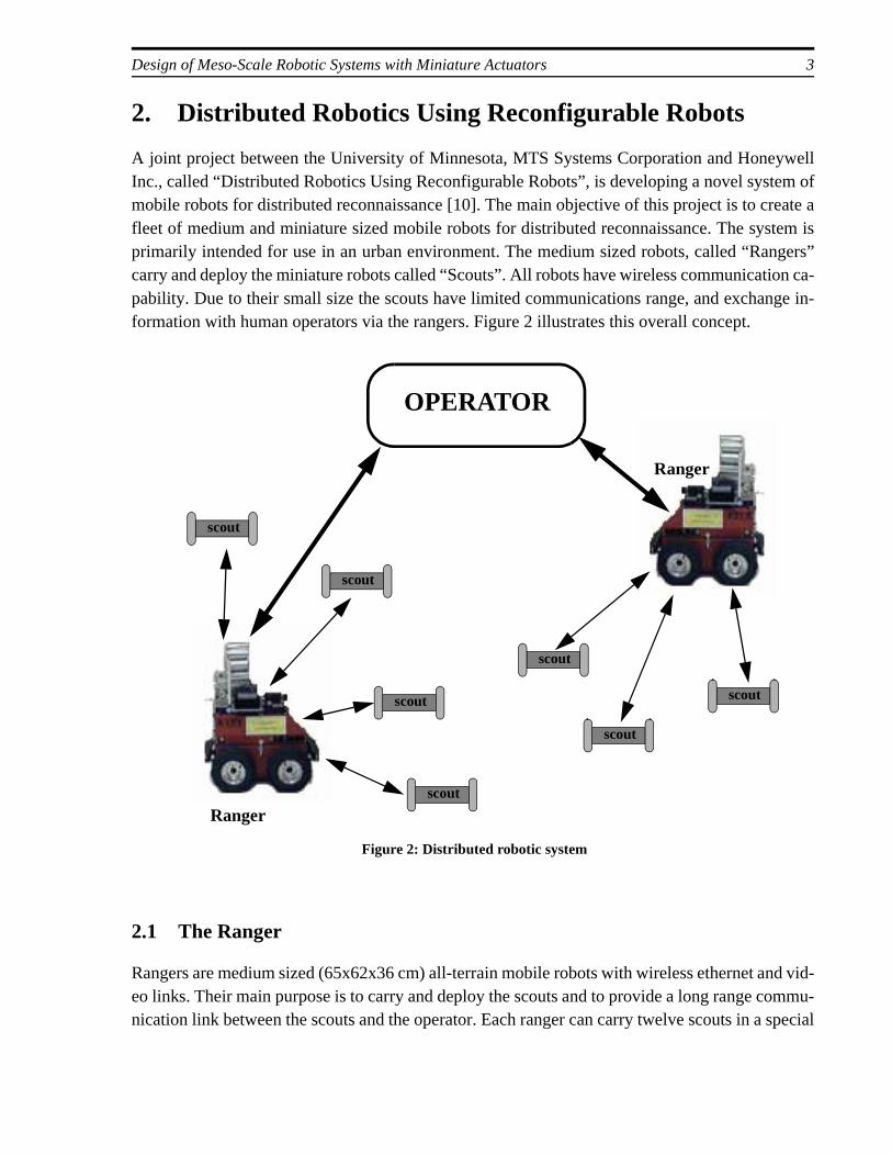
A joint project between the University of Minnesota, MTS Systems Corporation and HoneywellInc., called “Distributed Robotics Using Reconfigurable Robots”, is developing a novel systmobile robots for distributed reconnaissance [10]. The main objective of this project is to crfleet of medium and miniature sized mobile robots for distributed reconnaissance. The sysprimarily intended for use in an urban environment. The medium sized robots, called “Rancarry and deploy the miniature robots called “Scouts”. All robots have wireless communicatipability. Due to their small size the scouts have limited communications range, and exchaformation with human operators via the rangers. Figure 2 illustrates this overall concept.
2.1 The Ranger
Rangers are medium sized (65x62x36 cm) all-terrain mobile robots with wireless ethernet aeo links. Their main purpose is to carry and deploy the scouts and to provide a long range cnication link between the scouts and the operator. Each ranger can carry twelve scouts in a
Figure 2: Distributed robotic system
OPERATOR
Ranger
scout
scout
scout
scout
scout
scout
scout
Ranger
4 Tech Report UMN-AML-00-02
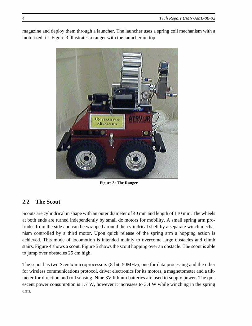
magazine and deploy them through a launcher. The launcher uses a spring coil mechanism with amotorized tilt. Figure 3 illustrates a ranger with the launcher on top.
2.2 The Scout
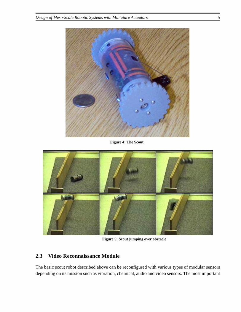
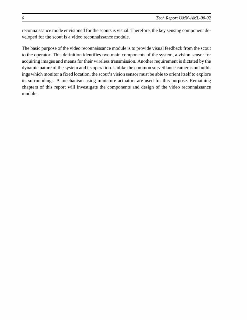
Scouts are cylindrical in shape with an outer diameter of 40 mm and length of 110 mm. The wheelsat both ends are turned independently by small dc motors for mobility. A small spring arm pro-trudes from the side and can be wrapped around the cylindrical shell by a separate winch mecha-nism controlled by a third motor. Upon quick release of the spring arm a hopping action isachieved. This mode of locomotion is intended mainly to overcome large obstacles and climbstairs. Figure 4 shows a scout. Figure 5 shows the scout hopping over an obstacle. The scout is ableto jump over obstacles 25 cm high.
The scout has two Scenix microprocessors (8-bit, 50MHz), one for data processing and the otherfor wireless communications protocol, driver electronics for its motors, a magnetometer and a tilt-meter for direction and roll sensing. Nine 3V lithium batteries are used to supply power. The qui-escent power consumption is 1.7 W, however it increases to 3.4 W while winching in the springarm.
Figure 3: The Ranger
Design of Meso-Scale Robotic Systems with Miniature Actuators 5
2.3 Video Reconnaissance Module
The basic scout robot described above can be reconfigured with various types of modular sensorsdepending on its mission such as vibration, chemical, audio and video sensors. The most important
Figure 4: The Scout
Figure 5: Scout jumping over obstacle
6 Tech Report UMN-AML-00-02
xploreaining
ssance
reconnaissance mode envisioned for the scouts is visual. Therefore, the key sensing component de-veloped for the scout is a video reconnaissance module.
The basic purpose of the video reconnaissance module is to provide visual feedback from the scoutto the operator. This definition identifies two main components of the system, a vision sensor foracquiring images and means for their wireless transmission. Another requirement is dictated by thedynamic nature of the system and its operation. Unlike the common surveillance cameras on build-ings which monitor a fixed location, the scout’s vision sensor must be able to orient itself to eits surroundings. A mechanism using miniature actuators are used for this purpose. Remchapters of this report will investigate the components and design of the video reconnaimodule.
Design of Meso-Scale Robotic Systems with Miniature Actuators 7
neratedre gen-bel the
3. Video Sensor and Wireless Transmission
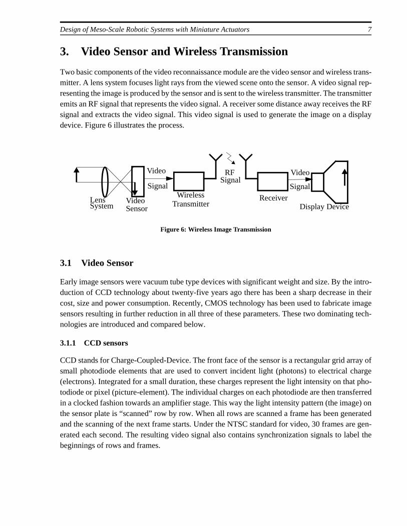
Two basic components of the video reconnaissance module are the video sensor and wireless trans-mitter. A lens system focuses light rays from the viewed scene onto the sensor. A video signal rep-resenting the image is produced by the sensor and is sent to the wireless transmitter. The transmitteremits an RF signal that represents the video signal. A receiver some distance away receives the RFsignal and extracts the video signal. This video signal is used to generate the image on a displaydevice. Figure 6 illustrates the process.
3.1 Video Sensor
Early image sensors were vacuum tube type devices with significant weight and size. By the intro-duction of CCD technology about twenty-five years ago there has been a sharp decrease in theircost, size and power consumption. Recently, CMOS technology has been used to fabricate imagesensors resulting in further reduction in all three of these parameters. These two dominating tech-nologies are introduced and compared below.
3.1.1 CCD sensors
CCD stands for Charge-Coupled-Device. The front face of the sensor is a rectangular grid array ofsmall photodiode elements that are used to convert incident light (photons) to electrical charge(electrons). Integrated for a small duration, these charges represent the light intensity on that pho-todiode or pixel (picture-element). The individual charges on each photodiode are then transferredin a clocked fashion towards an amplifier stage. This way the light intensity pattern (the image) onthe sensor plate is “scanned” row by row. When all rows are scanned a frame has been geand the scanning of the next frame starts. Under the NTSC standard for video, 30 frames aerated each second. The resulting video signal also contains synchronization signals to labeginnings of rows and frames.
Lens System
VideoSensor
Video
SignalWireless
TransmitterReceiver
Display Device
Figure 6: Wireless Image Transmission
Video
Signal
RF
Signal
8 Tech Report UMN-AML-00-02
Image sensors are manufactured in standard sizes and named by the approximate diagonal size ofthe sensor plate. A typical 1/3 inch CCD sensor will have a sensor plate of about 4.82mm x 3.64mm in size and contain 492 rows and 512 columns of pixels [7]. The total number of pixels and thesensor size determine the resolution of the sensor, therefore the larger the number of pixels per unitarea the higher the resolution.
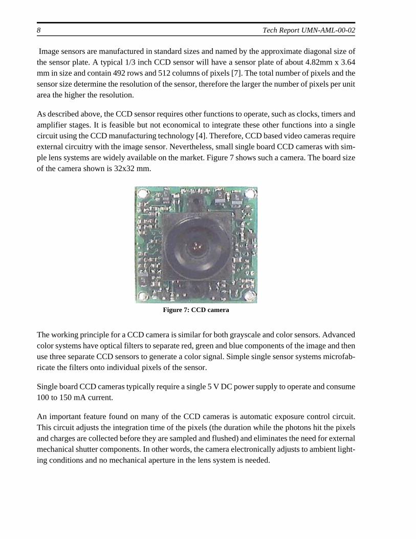
As described above, the CCD sensor requires other functions to operate, such as clocks, timers andamplifier stages. It is feasible but not economical to integrate these other functions into a singlecircuit using the CCD manufacturing technology [4]. Therefore, CCD based video cameras requireexternal circuitry with the image sensor. Nevertheless, small single board CCD cameras with sim-ple lens systems are widely available on the market. Figure 7 shows such a camera. The board sizeof the camera shown is 32x32 mm.
The working principle for a CCD camera is similar for both grayscale and color sensors. Advancedcolor systems have optical filters to separate red, green and blue components of the image and thenuse three separate CCD sensors to generate a color signal. Simple single sensor systems microfab-ricate the filters onto individual pixels of the sensor.
Single board CCD cameras typically require a single 5 V DC power supply to operate and consume100 to 150 mA current.
An important feature found on many of the CCD cameras is automatic exposure control circuit.This circuit adjusts the integration time of the pixels (the duration while the photons hit the pixelsand charges are collected before they are sampled and flushed) and eliminates the need for externalmechanical shutter components. In other words, the camera electronically adjusts to ambient light-ing conditions and no mechanical aperture in the lens system is needed.
Figure 7: CCD camera
Design of Meso-Scale Robotic Systems with Miniature Actuators 9
3.1.2 CMOS sensors
CMOS (Complementary Metal-Oxide Semiconductor) technology is widely used for semiconduc-tor device manufacturing. It has recently been applied to image sensors resulting in considerableimprovements in size, cost and power consumption.
Both CMOS and CCD sensors use the same photoconversion process to convert incident photonsto electrical charge. For the CMOS sensor, however, these charges are not transferred from the pix-els but amplified at the point of collection by dedicated CMOS transistors [4]. Thus, every pixelhas its own amplification circuitry.
The two main advantages of CMOS sensors over CCDs result from the wide application of CMOStechnology in industry. In addition to reducing the manufacturing cost, the use of well developedCMOS technology facilitates the integration of all camera functions into a single VLSI package.Therefore, several single-chip video cameras are available on the market at very low costs. Addi-tionally, they typically consume three to five times less power than similar CCD based cameras.
CCD sensors are known to have better image quality compared to CMOS sensors. One majorproblem with the CMOS sensor was the fixed pattern noise resulting from the unmatched transistorcharacteristics at each pixel [4]. However, this problem has been greatly reduced. Today, CMOSsensor manufacturers claim to have reached the image quality of common CCD sensors.
An analog video signal is not the only output option on single-chip cameras. Several manufacturersmake sensors with digital output. These are especially useful with PC based systems since the nec-essary digitization is already done in the camera. However, transmission of digital images requiresa high bandwidth communication link. The current wireless link on the scout is limited to 2.4 kbpswhich is too low for the real-time video requirements dictated by the distributed robotics project.
As previously explained, CMOS sensor based cameras have advantages over the CCDs in term ofsize, power consumption and cost. Therefore, a CMOS sensor based camera system was selectedfor the video reconnaissance module. The monochrome sensor selected is a BV5016 by OmniVi-sion. A pinhole lens with a 5.7 mm focal length is used to focus the image onto the video sensor.The resulting sensor-lens package is approximately 15x15x16 mm in size and weighs 3.5 grams.Table 1 summarizes the specification
10 Tech Report UMN-AML-00-02
3.2 Wireless transmitter
A number of wireless video transmitters are available on the market with various sizes and powerconsumption values. Table 2 summarizes the specifications of some commercially available min-iature transmitters.
An important design criterion for the transmitter is the operating frequency. Commercial transmit-ters of small size operate in three different bands reserved by the FCC for unlicensed operation,namely the 440 MHz ATV (Amateur TV) band, the 900 MHz ISM (Industrial , Scientific, Medical)band, and the 2.4 GHz band. Generally, the higher the frequency the longer the transmission rangefor a given transmitting power. On the other hand, higher frequency waves concentrate more oftheir power in one direction. Therefore high frequency transmitters perform better in line-of-sightapplications (i.e. when the transmitter antenna and the receiver antenna are in line-of-sight) but aremore sensitive to alignment of the transmitter and receiver antennas.
Most transmitters use Frequency Modulation (FM) while some use Amplitude Modulation (AM).In general, FM systems have less noise and signal degradation compared to AM systems.
Table 1: Camera Specifications
Sensor type Single-chip monochrome CMOS sensor with 320x240 pixels
Size 15 x 15 x 16 mm
Power consump-tion
20 mA at 6-9 VDC
Output Composite video signal, 2 V p-p at 30 frame/second
Lens Pinhole lens 5.7 mm focal length
Table 2: Miniature Video Transmitters
Model/Manufacturer
Size [mm] Frequency Range Specification
Power
Vid-Link 100Virtual Spy
28 x 20 x 10 434 MHz 150 m 35 mA, 9 V
MV915Micro Video Products
24 x 17 x 8 915 MHz 300 m 30 mA, 9 V
MP-1 MicroplateSupercircuits
50 x 32 x 4 434 MHz 200 m 100 mA, 12 V
T900VApplied-wireless
40 x 20 x 7 900 MHz 150 m 20 mA, 3 V
Design of Meso-Scale Robotic Systems with Miniature Actuators 11
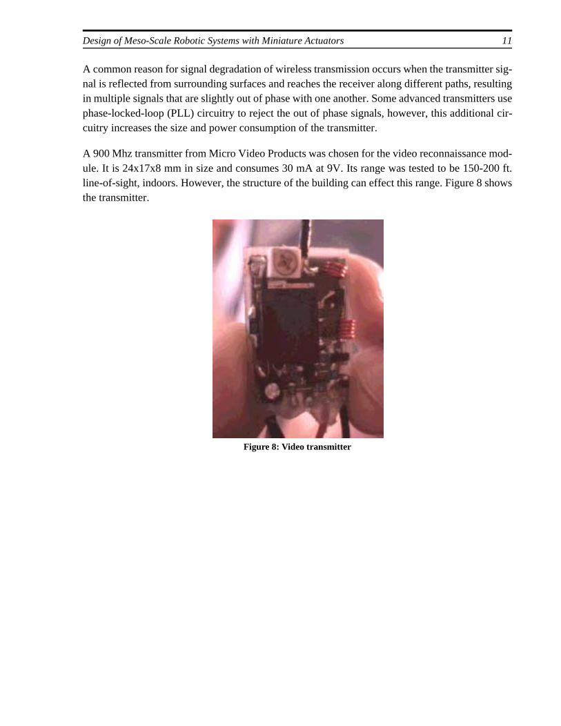
A common reason for signal degradation of wireless transmission occurs when the transmitter sig-nal is reflected from surrounding surfaces and reaches the receiver along different paths, resultingin multiple signals that are slightly out of phase with one another. Some advanced transmitters usephase-locked-loop (PLL) circuitry to reject the out of phase signals, however, this additional cir-cuitry increases the size and power consumption of the transmitter.
A 900 Mhz transmitter from Micro Video Products was chosen for the video reconnaissance mod-ule. It is 24x17x8 mm in size and consumes 30 mA at 9V. Its range was tested to be 150-200 ft.line-of-sight, indoors. However, the structure of the building can effect this range. Figure 8 showsthe transmitter.
Figure 8: Video transmitter
12 Tech Report UMN-AML-00-02
es and. A veryat an
called
l mate-irconate
c prop->2000align-lectricl to thepplied
4. Actuators for Miniature Systems
With the advent of technologies like VLSI and SMT (Surface-Mount-Technology), there has beena great reduction in size of electronics which has caused a further drive to miniaturize many prod-ucts. The leading edge in this trend is MEMS (Micro Electro-Mechanical Systems) technology,which is itself an offshoot of silicon manufacturing. MEMS fabrication uses photo-chemical pro-cesses similar to the VLSI industry for creating mechanical structures with millimeter to microndimensions. Almost all successful commercial applications of MEMS are sensors, though researchis performed worldwide to develop micro-actuation mechanisms. However difficulties exist in theminiaturization of actuators due to both manufacturing issues and scaling effects. As the parts getsmaller, inertial (volumetric) forces tend to loose their dominance over surface effect forces suchas electrostatics [25].
Despite these difficulties many attempts to develop microscale actuators have been pursued. Mi-croactuators can be classified into two major groups [11] : those using electrostatic and electromag-netic forces (for example electric motors) and those that use a functional element. Two well knownexamples of the latter type are actuators using piezo-ceramic materials and those using shape mem-ory alloys. These actuators can also be used in meso-scale systems however, their effectiveness isnaturally quite different at this scale than at the microscale. Additionally, the power requirementsand control of these actuators will be different and these differences become even more importantin miniature robotic systems with limited on-board resources. In this chapter, the three most com-mon types of actuators will be examined from the perspective of their utility for miniature roboticsystems.
4.1 Piezoelectric Actuators
The word “piezo” is derived from the Greek word for pressure. Discovered in 1880 by JacquPierre Curie, piezoelectric materials create an electric charge when under mechanical stresscommon natural piezoelectric material is quartz. Initial experiments with quartz showed thelectric field applied across the crystal would generate mechanical strains as well. This isthe inverse piezoelectric effect and is the working principle of all piezoelectric actuators.
Special ceramics that exhibit the piezoelectric effect to a greater extend compared to naturarials have been developed. Perhaps the most common of these special ceramics is Lead ZTitanate (PZT). Raw PZT material is treated in a process called poling to induce piezoelectrierties [19]. In this process, PZT ceramic is heated and a strong electric field is applied (V/mm). This creates groups of dipoles with parallel orientation called Weiss domains. This ment is roughly maintained after cooling and the ceramic is poled. After poling, when an efield is applied across the ceramic, the Weiss domains increase their alignment proportionaapplied voltage. With the increased alignment, the ceramic expands in the direction of the a
Design of Meso-Scale Robotic Systems with Miniature Actuators 13
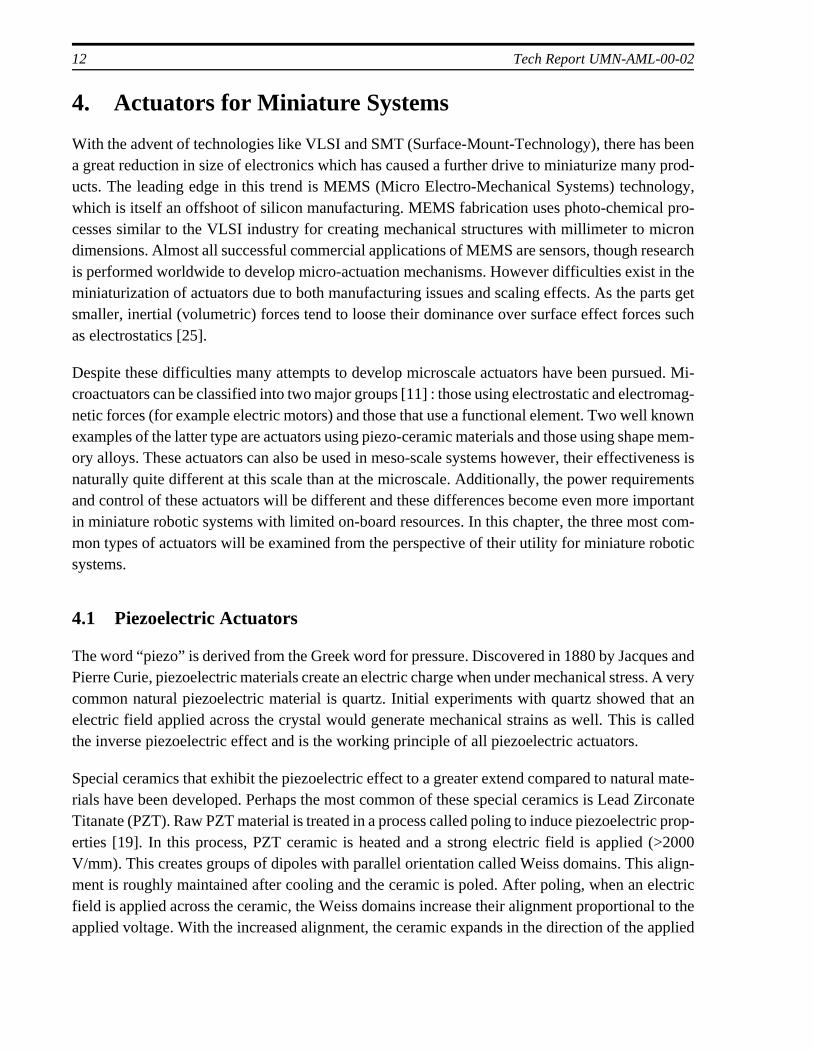
field and contracts in the perpendicular axes. This creates a linear actuator. Figure 9 illustrates thepoling process.
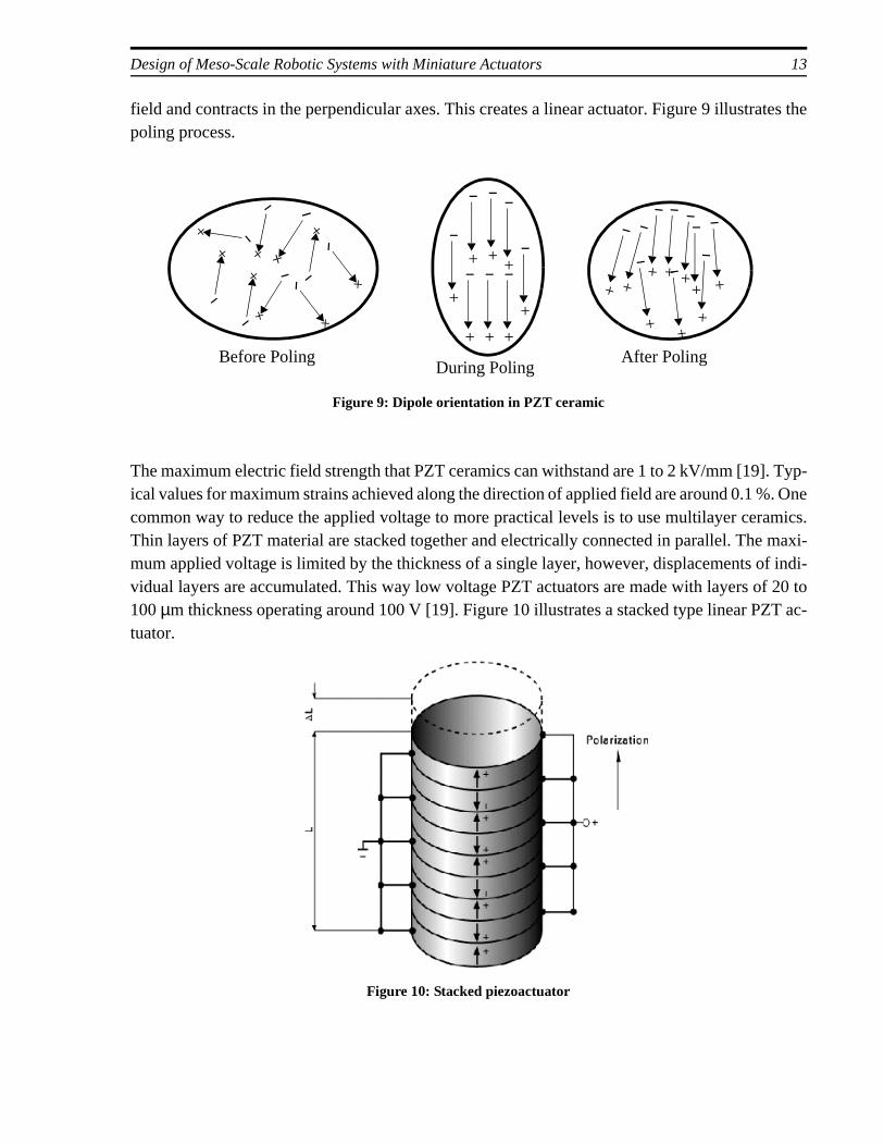
The maximum electric field strength that PZT ceramics can withstand are 1 to 2 kV/mm [19]. Typ-ical values for maximum strains achieved along the direction of applied field are around 0.1 %. Onecommon way to reduce the applied voltage to more practical levels is to use multilayer ceramics.Thin layers of PZT material are stacked together and electrically connected in parallel. The maxi-mum applied voltage is limited by the thickness of a single layer, however, displacements of indi-vidual layers are accumulated. This way low voltage PZT actuators are made with layers of 20 to100 µm thickness operating around 100 V [19]. Figure 10 illustrates a stacked type linear PZT ac-tuator.
Figure 9: Dipole orientation in PZT ceramic
-+
-
+-
+
-
+
-
+
-
+
-
+
-
+-
+
-
+
-
+
-
+
-
+-
+
-
+
-
+
-
+
-
+
-
+
-
+ -
+
-
+
-
+
-
+
-
+
-
+
-
+
Before PolingDuring Poling
After Poling
Figure 10: Stacked piezoactuator
14 Tech Report UMN-AML-00-02
Piezoelectric actuators theoretically have infinite resolution. Practically, the resolution is degradedby control electronics, noise, mechanical inaccuracies, hysteresis effects and creep. Nevertheless,sub-nanometer resolution is achievable making them the actuator of choice in many precision ap-plications with small displacement needs.
Actuator designs for higher displacement usually employ a mechanical leverage to increase travel.Typically, a mechanism working close to a kinematic singularity is used for high magnification[16]. Simple PZT actuators (i.e. without mechanical magnification) have high stiffness and have acontrolled bandwidth of several kHz. Mechanical amplification may reduce both stiffness andbandwidth.
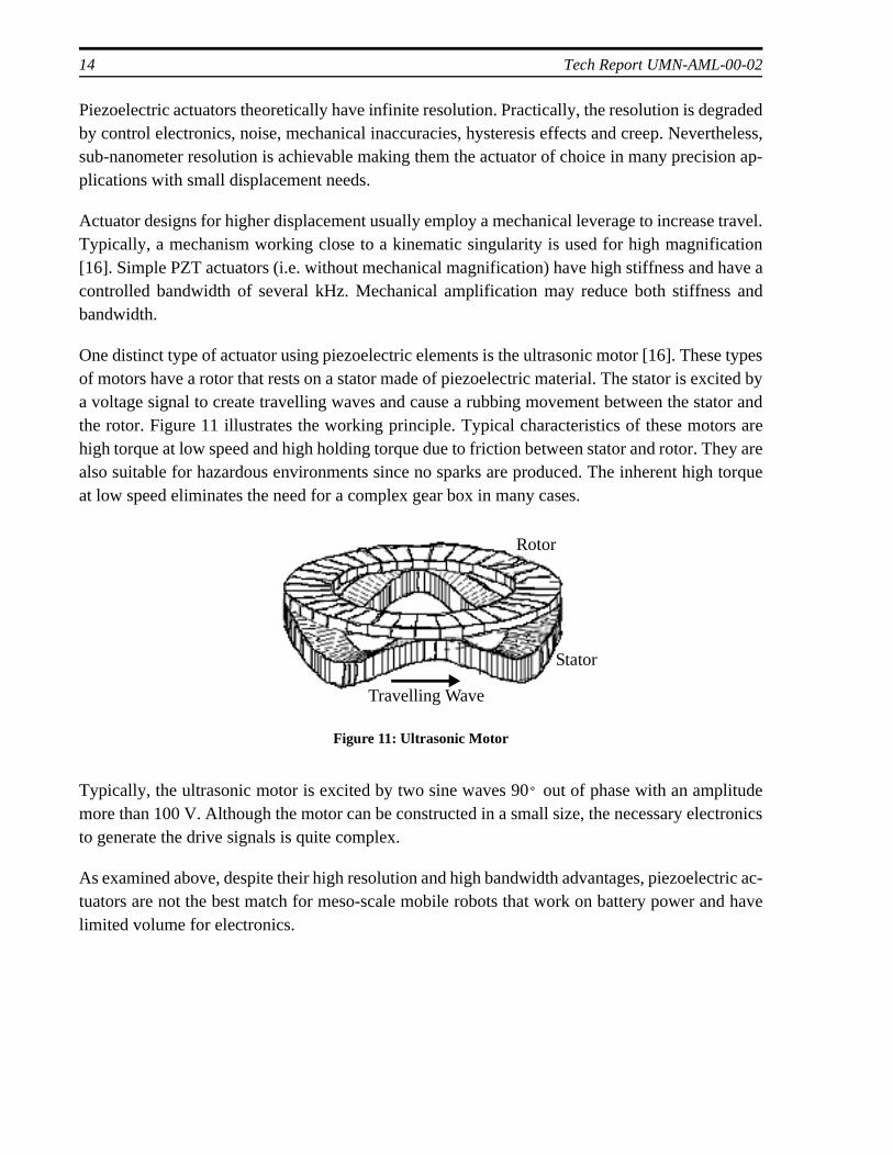
One distinct type of actuator using piezoelectric elements is the ultrasonic motor [16]. These typesof motors have a rotor that rests on a stator made of piezoelectric material. The stator is excited bya voltage signal to create travelling waves and cause a rubbing movement between the stator andthe rotor. Figure 11 illustrates the working principle. Typical characteristics of these motors arehigh torque at low speed and high holding torque due to friction between stator and rotor. They arealso suitable for hazardous environments since no sparks are produced. The inherent high torqueat low speed eliminates the need for a complex gear box in many cases.
Typically, the ultrasonic motor is excited by two sine waves 90 out of phase with an amplitudemore than 100 V. Although the motor can be constructed in a small size, the necessary electronicsto generate the drive signals is quite complex.
As examined above, despite their high resolution and high bandwidth advantages, piezoelectric ac-tuators are not the best match for meso-scale mobile robots that work on battery power and havelimited volume for electronics.
Figure 11: Ultrasonic Motor
Rotor
Stator
Travelling Wave
°
Design of Meso-Scale Robotic Systems with Miniature Actuators 15
4.2 Shape Memory Alloy (SMA) Actuators
Shape memory alloys are metallic materials with a unique ability to change their shape at theirtransformation temperature. When the metal is deformed and then heated above this temperatureit recovers its original shape and is able to exert a large force during recovery. This property hasbeen utilized in many different ways including actuation.
Shape Memory effect was first observed in a AuCd component in 1932 [9] and in a CuZn compo-nent in 1938. However, it was not until 1962 that the effect was discovered in nickel-titanium (Ni-Ti) alloys which are the most common type of shape memory alloy on the market today.
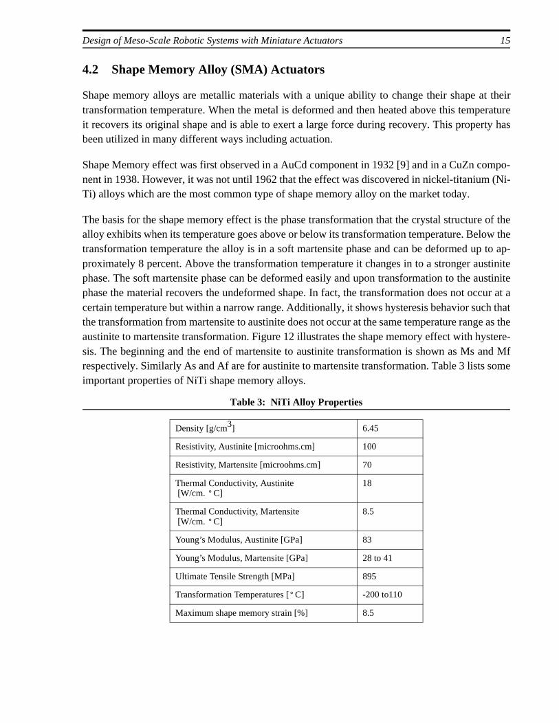
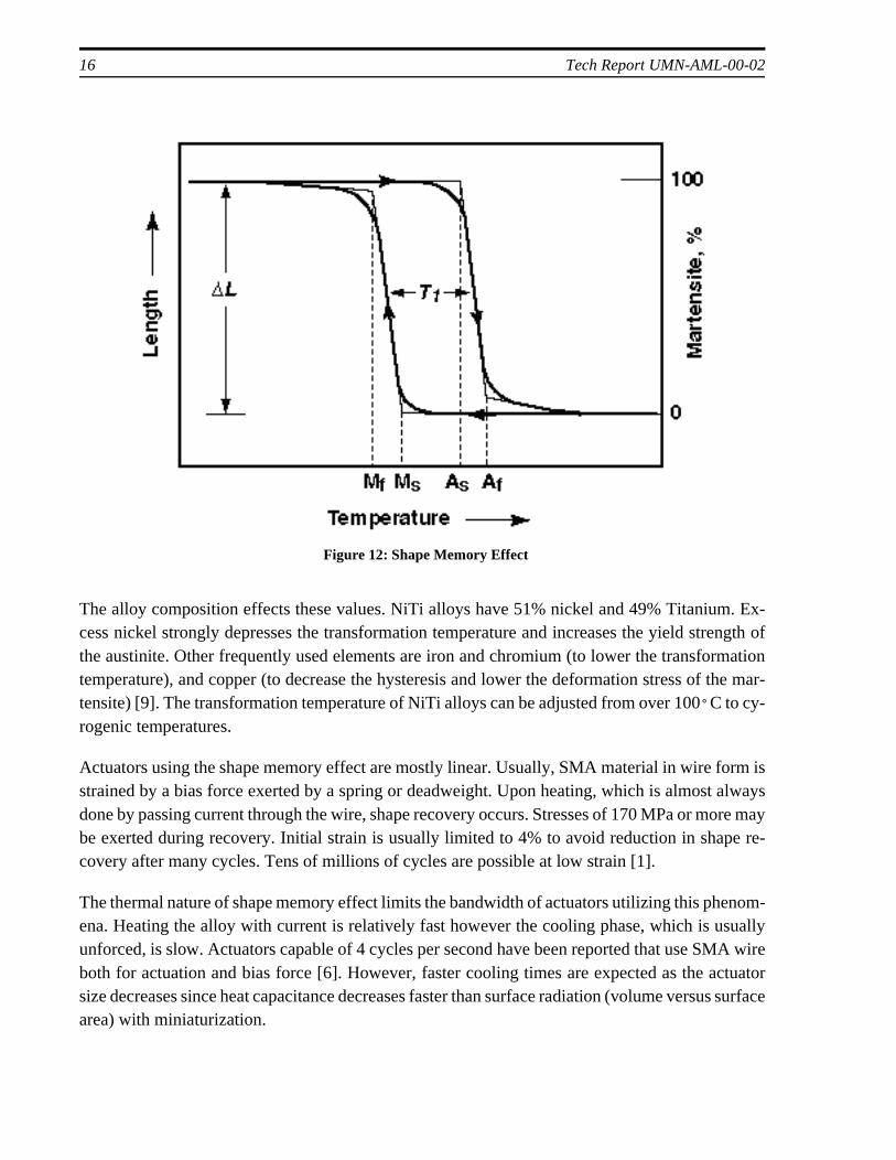
The basis for the shape memory effect is the phase transformation that the crystal structure of thealloy exhibits when its temperature goes above or below its transformation temperature. Below thetransformation temperature the alloy is in a soft martensite phase and can be deformed up to ap-proximately 8 percent. Above the transformation temperature it changes in to a stronger austinitephase. The soft martensite phase can be deformed easily and upon transformation to the austinitephase the material recovers the undeformed shape. In fact, the transformation does not occur at acertain temperature but within a narrow range. Additionally, it shows hysteresis behavior such thatthe transformation from martensite to austinite does not occur at the same temperature range as theaustinite to martensite transformation. Figure 12 illustrates the shape memory effect with hystere-sis. The beginning and the end of martensite to austinite transformation is shown as Ms and Mfrespectively. Similarly As and Af are for austinite to martensite transformation. Table 3 lists someimportant properties of NiTi shape memory alloys.
Table 3: NiTi Alloy Properties
Density [g/cm3] 6.45
Resistivity, Austinite [microohms.cm] 100
Resistivity, Martensite [microohms.cm] 70
Thermal Conductivity, Austinite [W/cm. C]
18
Thermal Conductivity, Martensite [W/cm. C]
8.5
Young’s Modulus, Austinite [GPa] 83
Young’s Modulus, Martensite [GPa] 28 to 41
Ultimate Tensile Strength [MPa] 895
Transformation Temperatures [ C] -200 to110
Maximum shape memory strain [%] 8.5
°
°
°
16 Tech Report UMN-AML-00-02
The alloy composition effects these values. NiTi alloys have 51% nickel and 49% Titanium. Ex-cess nickel strongly depresses the transformation temperature and increases the yield strength ofthe austinite. Other frequently used elements are iron and chromium (to lower the transformationtemperature), and copper (to decrease the hysteresis and lower the deformation stress of the mar-tensite) [9]. The transformation temperature of NiTi alloys can be adjusted from over 100 C to cy-rogenic temperatures.
Actuators using the shape memory effect are mostly linear. Usually, SMA material in wire form isstrained by a bias force exerted by a spring or deadweight. Upon heating, which is almost alwaysdone by passing current through the wire, shape recovery occurs. Stresses of 170 MPa or more maybe exerted during recovery. Initial strain is usually limited to 4% to avoid reduction in shape re-covery after many cycles. Tens of millions of cycles are possible at low strain [1].
The thermal nature of shape memory effect limits the bandwidth of actuators utilizing this phenom-ena. Heating the alloy with current is relatively fast however the cooling phase, which is usuallyunforced, is slow. Actuators capable of 4 cycles per second have been reported that use SMA wireboth for actuation and bias force [6]. However, faster cooling times are expected as the actuatorsize decreases since heat capacitance decreases faster than surface radiation (volume versus surfacearea) with miniaturization.
Figure 12: Shape Memory Effect
°
Design of Meso-Scale Robotic Systems with Miniature Actuators 17
The biggest advantage of SMA based actuators is their simplicity and thus reliability. Also thepower to weight ratio is high. However, they are usually on-off type actuators without position con-trol.
4.3 Electro-Mechanical Actuators
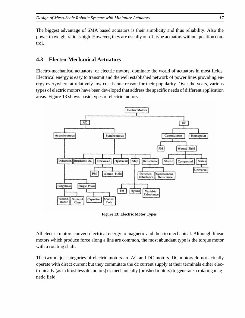
Electro-mechanical actuators, or electric motors, dominate the world of actuators in most fields.Electrical energy is easy to transmit and the well established network of power lines providing en-ergy everywhere at relatively low cost is one reason for their popularity. Over the years, varioustypes of electric motors have been developed that address the specific needs of different applicationareas. Figure 13 shows basic types of electric motors.
All electric motors convert electrical energy to magnetic and then to mechanical. Although linearmotors which produce force along a line are common, the most abundant type is the torque motorwith a rotating shaft.
The two major categories of electric motors are AC and DC motors. DC motors do not actuallyoperate with direct current but they commutate the dc current supply at their terminals either elec-tronically (as in brushless dc motors) or mechanically (brushed motors) to generate a rotating mag-netic field.
Figure 13: Electric Motor Types
18 Tech Report UMN-AML-00-02
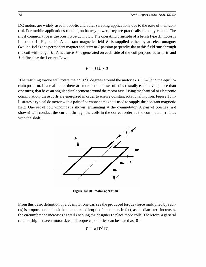
DC motors are widely used in robotic and other servoing applications due to the ease of their con-trol. For mobile applications running on battery power, they are practically the only choice. Themost common type is the brush type dc motor. The operating principle of a brush type dc motor isillustrated in Figure 14. A constant magnetic field is supplied either by an electromagnet(wound-field) or a permanent magnet and current passing perpendicular to this field runs throughthe coil with length . A net force is generated on each side of the coil perpendicular to and
defined by the Lorentz Law:
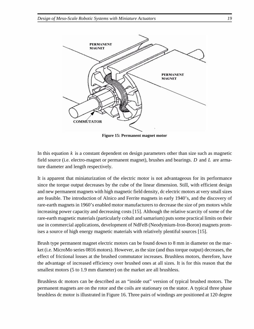
The resulting torque will rotate the coils 90 degrees around the motor axis to the equilib-rium position. In a real motor there are more than one set of coils (usually each having more thanone turns) that have an angular displacement around the motor axis. Using mechanical or electroniccommutation, these coils are energized in order to ensure constant rotational motion. Figure 15 il-lustrates a typical dc motor with a pair of permanent magnets used to supply the constant magneticfield. One set of coil windings is shown terminating at the commutator. A pair of brushes (notshown) will conduct the current through the coils in the correct order as the commutator rotateswith the shaft.
From this basic definition of a dc motor one can see the produced torque (force multiplied by radi-us) is proportional to both the diameter and length of the motor. In fact, as the diameter increases,the circumference increases as well enabling the designer to place more coils. Therefore, a generalrelationship between motor size and torque capabilities can be stated as [8] :
BI
L F BI
F I L B×⋅=
O′ O–
Figure 14: DC motor operation
F
F
I
B
T k D2 L⋅ ⋅=
Design of Meso-Scale Robotic Systems with Miniature Actuators 19
ery ofrs while of then their
prom-
e mar-ses, thee, havethat the
rs. Thee phasedegree
In this equation is a constant dependent on design parameters other than size such as magneticfield source (i.e. electro-magnet or permanent magnet), brushes and bearings. and are arma-ture diameter and length respectively.
It is apparent that miniaturization of the electric motor is not advantageous for its performancesince the torque output decreases by the cube of the linear dimension. Still, with efficient designand new permanent magnets with high magnetic field density, dc electric motors at very small sizesare feasible. The introduction of Alnico and Ferrite magnets in early 1940’s, and the discovrare-earth magnets in 1960’s enabled motor manufacturers to decrease the size of pm motoincreasing power capacity and decreasing costs [15]. Although the relative scarcity of somerare-earth magnetic materials (particularly cobalt and samarium) puts some practical limits ouse in commercial applications, development of NdFeB (Neodymium-Iron-Boron) magnets ises a source of high energy magnetic materials with relatively plentiful sources [15].
Brush type permanent magnet electric motors can be found down to 8 mm in diameter on thket (i.e. MicroMo series 0816 motors). However, as the size (and thus torque output) decreaeffect of frictional losses at the brushed commutator increases. Brushless motors, thereforthe advantage of increased efficiency over brushed ones at all sizes. It is for this reason smallest motors (5 to 1.9 mm diameter) on the market are all brushless.
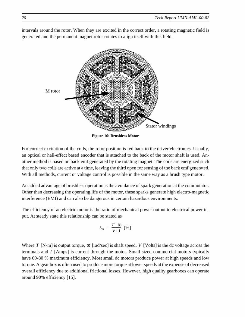
Brushless dc motors can be described as an “inside out” version of typical brushed motopermanent magnets are on the rotor and the coils are stationary on the stator. A typical threbrushless dc motor is illustrated in Figure 16. Three pairs of windings are positioned at 120
COMMUTATOR
Figure 15: Permanent magnet motor
kD L
20 Tech Report UMN-AML-00-02
intervals around the rotor. When they are excited in the correct order, a rotating magnetic field isgenerated and the permanent magnet rotor rotates to align itself with this field.
For correct excitation of the coils, the rotor position is fed back to the driver electronics. Usually,an optical or hall-effect based encoder that is attached to the back of the motor shaft is used. An-other method is based on back emf generated by the rotating magnet. The coils are energized suchthat only two coils are active at a time, leaving the third open for sensing of the back emf generated.With all methods, current or voltage control is possible in the same way as a brush type motor.
An added advantage of brushless operation is the avoidance of spark generation at the commutator.Other than decreasing the operating life of the motor, these sparks generate high electro-magneticinterference (EMI) and can also be dangerous in certain hazardous environments.
The efficiency of an electric motor is the ratio of mechanical power output to electrical power in-put. At steady state this relationship can be stated as
Where [N-m] is output torque, [rad/sec] is shaft speed, [Volts] is the dc voltage across theterminals and [Amps] is current through the motor. Small sized commercial motors typicallyhave 60-80 % maximum efficiency. Most small dc motors produce power at high speeds and lowtorque. A gear box is often used to produce more torque at lower speeds at the expense of decreasedoverall efficiency due to additional frictional losses. However, high quality gearboxes can operatearound 90% efficiency [15].
M rotor
Stator windings
Figure 16: Brushless Motor
εmT ω⋅V I⋅----------- [%]=
T ω VI
Design of Meso-Scale Robotic Systems with Miniature Actuators 21
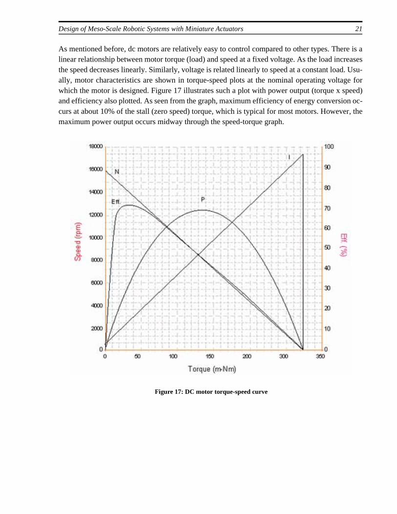
As mentioned before, dc motors are relatively easy to control compared to other types. There is alinear relationship between motor torque (load) and speed at a fixed voltage. As the load increasesthe speed decreases linearly. Similarly, voltage is related linearly to speed at a constant load. Usu-ally, motor characteristics are shown in torque-speed plots at the nominal operating voltage forwhich the motor is designed. Figure 17 illustrates such a plot with power output (torque x speed)and efficiency also plotted. As seen from the graph, maximum efficiency of energy conversion oc-curs at about 10% of the stall (zero speed) torque, which is typical for most motors. However, themaximum power output occurs midway through the speed-torque graph.
Figure 17: DC motor torque-speed curve
22 Tech Report UMN-AML-00-02
5. DESIGN WITH MINIATURE ACTUATORS
As an application of miniature actuators, design of the video reconnaissance module is presentedin this chapter. The required properties of the system are defined and alternative designs are devel-oped. Issues in mechanical design with miniature actuators and their control electronics are exam-ined.
5.1 Specifications for the Video Reconnaissance Module
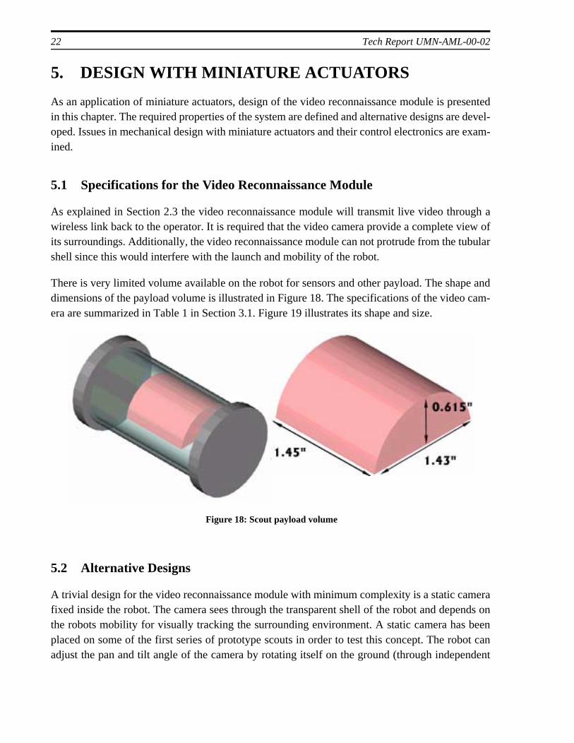
As explained in Section 2.3 the video reconnaissance module will transmit live video through awireless link back to the operator. It is required that the video camera provide a complete view ofits surroundings. Additionally, the video reconnaissance module can not protrude from the tubularshell since this would interfere with the launch and mobility of the robot.
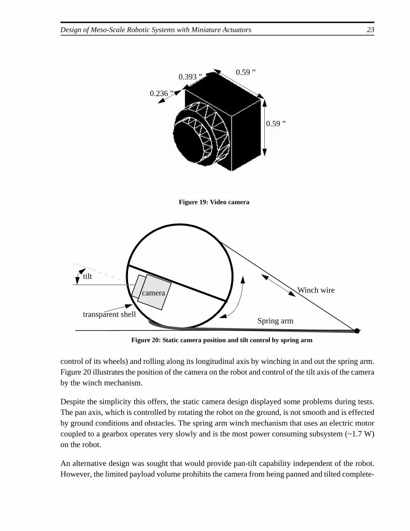
There is very limited volume available on the robot for sensors and other payload. The shape anddimensions of the payload volume is illustrated in Figure 18. The specifications of the video cam-era are summarized in Table 1 in Section 3.1. Figure 19 illustrates its shape and size.
5.2 Alternative Designs
A trivial design for the video reconnaissance module with minimum complexity is a static camerafixed inside the robot. The camera sees through the transparent shell of the robot and depends onthe robots mobility for visually tracking the surrounding environment. A static camera has beenplaced on some of the first series of prototype scouts in order to test this concept. The robot canadjust the pan and tilt angle of the camera by rotating itself on the ground (through independent
Figure 18: Scout payload volume
Design of Meso-Scale Robotic Systems with Miniature Actuators 23
control of its wheels) and rolling along its longitudinal axis by winching in and out the spring arm.Figure 20 illustrates the position of the camera on the robot and control of the tilt axis of the cameraby the winch mechanism.
Despite the simplicity this offers, the static camera design displayed some problems during tests.The pan axis, which is controlled by rotating the robot on the ground, is not smooth and is effectedby ground conditions and obstacles. The spring arm winch mechanism that uses an electric motorcoupled to a gearbox operates very slowly and is the most power consuming subsystem (~1.7 W)on the robot.
An alternative design was sought that would provide pan-tilt capability independent of the robot.However, the limited payload volume prohibits the camera from being panned and tilted complete-
Figure 19: Video camera
0.236 ”
0.393 ”0.59 ”
0.59 ”
Spring arm
Winch wire
transparent shell
Figure 20: Static camera position and tilt control by spring arm
tilt
camera
24 Tech Report UMN-AML-00-02
ly inside the robot. Therefore, in addition to pan and tilt action, a third component of motion toraise the camera outside the shell and retract it is needed. The first generation video reconnais-sance module (VRM-1) was designed and built to meet these specifications.
5.3 First Generation Video Reconnaissance Module (VRM-1)
5.3.1 Mechanical construction
With the specifications on the video camera and payload volume fixed, a mechanical system to addpan, tilt and pop-out/retract capabilities to the camera was designed.
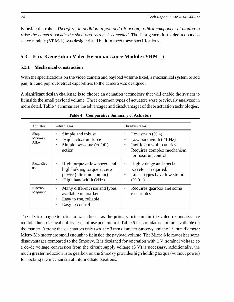
A significant design challenge is to choose an actuation technology that will enable the system tofit inside the small payload volume. Three common types of actuators were previously analyzed inmore detail. Table 4 summarizes the advantages and disadvantages of these actuation technologies.
The electro-magnetic actuator was chosen as the primary actuator for the video reconnaissancemodule due to its availability, ease of use and control. Table 5 lists miniature motors available onthe market. Among these actuators only two, the 3 mm diameter Smoovy and the 1.9 mm diameterMicro-Mo motor are small enough to fit inside the payload volume. The Micro-Mo motor has somedisadvantages compared to the Smoovy. It is designed for operation with 1 V nominal voltage soa dc-dc voltage conversion from the circuit supply voltage (5 V) is necessary. Additionally, themuch greater reduction ratio gearbox on the Smoovy provides high holding torque (without power)for locking the mechanism at intermediate positions.
Table 4: Comparative Summary of Actuators
Actuator Advantages Disadvantages
Shape Memory Alloy
• Simple and robust• High actuation force • Simple two-state (on/off)
action
• Low strain (% 4)• Low bandwidth (<1 Hz)• Inefficient with batteries• Requires complex mechanism
for position control
PiezoElec-tric
• High torque at low speed and high holding torque at zero power (ultrasonic motor)
• High bandwidth (kHz)
• High voltage and special waveform required.
• Linear types have low strain (% 0.1)
Electro-Magnetic
• Many different size and types available on market
• Easy to use, reliable• Easy to control
• Requires gearbox and some electronics
Design of Meso-Scale Robotic Systems with Miniature Actuators 25
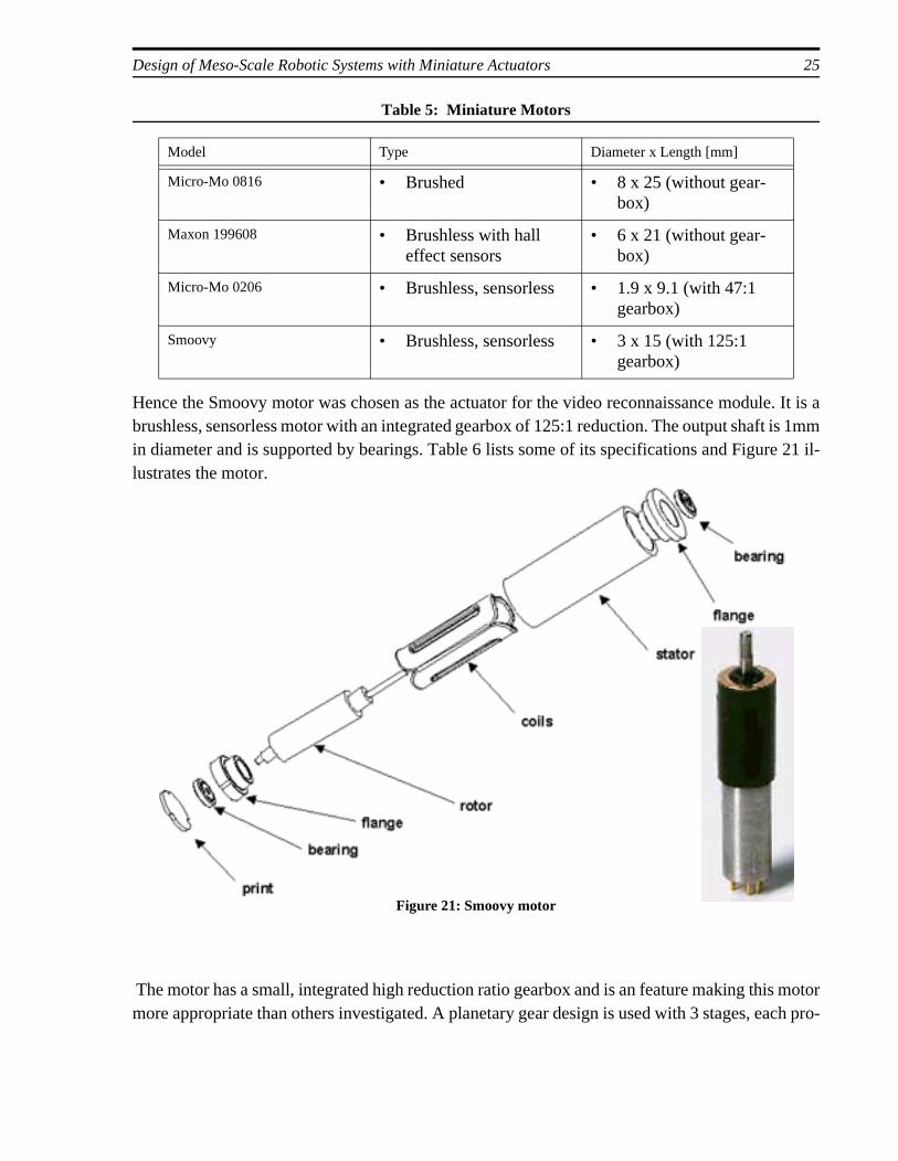
Hence the Smoovy motor was chosen as the actuator for the video reconnaissance module. It is abrushless, sensorless motor with an integrated gearbox of 125:1 reduction. The output shaft is 1mmin diameter and is supported by bearings. Table 6 lists some of its specifications and Figure 21 il-lustrates the motor.
The motor has a small, integrated high reduction ratio gearbox and is an feature making this motormore appropriate than others investigated. A planetary gear design is used with 3 stages, each pro-
Table 5: Miniature Motors
Model Type Diameter x Length [mm]
Micro-Mo 0816 • Brushed • 8 x 25 (without gear-box)
Maxon 199608 • Brushless with hall effect sensors
• 6 x 21 (without gear-box)
Micro-Mo 0206 • Brushless, sensorless • 1.9 x 9.1 (with 47:1 gearbox)
Smoovy • Brushless, sensorless • 3 x 15 (with 125:1 gearbox)
Figure 21: Smoovy motor
26 Tech Report UMN-AML-00-02
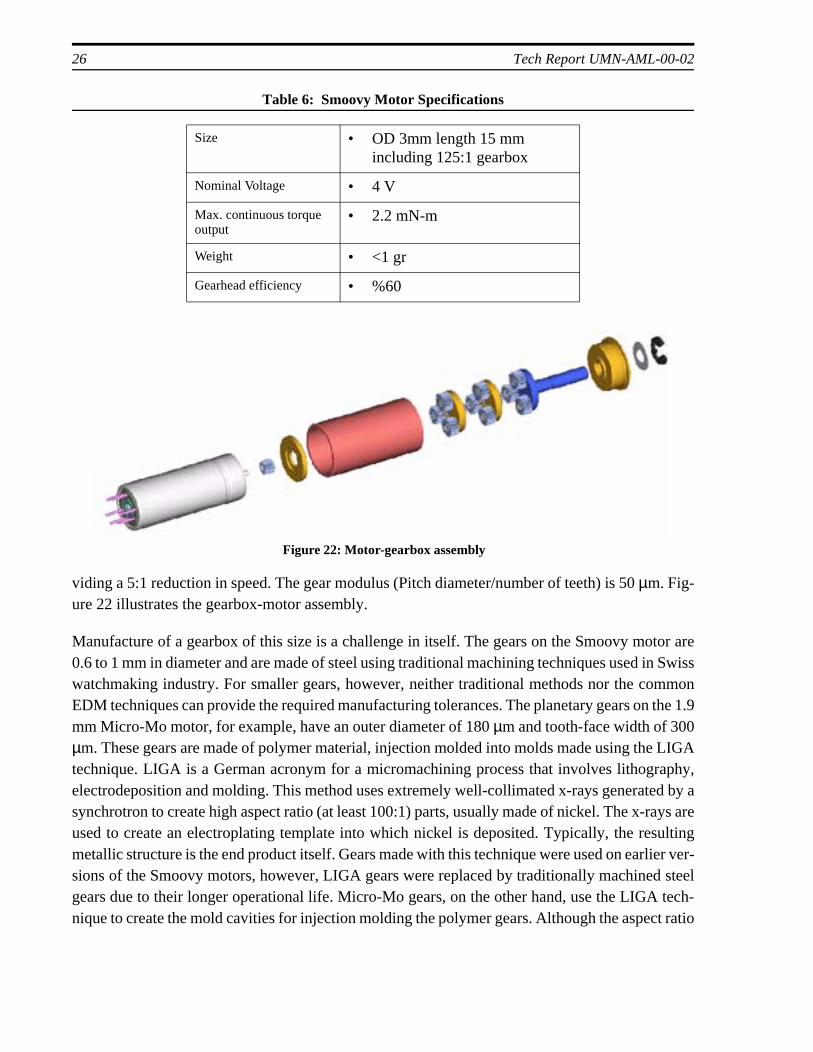
viding a 5:1 reduction in speed. The gear modulus (Pitch diameter/number of teeth) is 50 µm. Fig-ure 22 illustrates the gearbox-motor assembly.
Manufacture of a gearbox of this size is a challenge in itself. The gears on the Smoovy motor are0.6 to 1 mm in diameter and are made of steel using traditional machining techniques used in Swisswatchmaking industry. For smaller gears, however, neither traditional methods nor the commonEDM techniques can provide the required manufacturing tolerances. The planetary gears on the 1.9mm Micro-Mo motor, for example, have an outer diameter of 180 µm and tooth-face width of 300µm. These gears are made of polymer material, injection molded into molds made using the LIGAtechnique. LIGA is a German acronym for a micromachining process that involves lithography,electrodeposition and molding. This method uses extremely well-collimated x-rays generated by asynchrotron to create high aspect ratio (at least 100:1) parts, usually made of nickel. The x-rays areused to create an electroplating template into which nickel is deposited. Typically, the resultingmetallic structure is the end product itself. Gears made with this technique were used on earlier ver-sions of the Smoovy motors, however, LIGA gears were replaced by traditionally machined steelgears due to their longer operational life. Micro-Mo gears, on the other hand, use the LIGA tech-nique to create the mold cavities for injection molding the polymer gears. Although the aspect ratio
Table 6: Smoovy Motor Specifications
Size • OD 3mm length 15 mm including 125:1 gearbox
Nominal Voltage • 4 V
Max. continuous torque output
• 2.2 mN-m
Weight • <1 gr
Gearhead efficiency • %60
Figure 22: Motor-gearbox assembly
Design of Meso-Scale Robotic Systems with Miniature Actuators 27
is not large (180:360), LIGA provides smooth wall surfaces and close tolerances that also aid intaking the parts out of the mold.
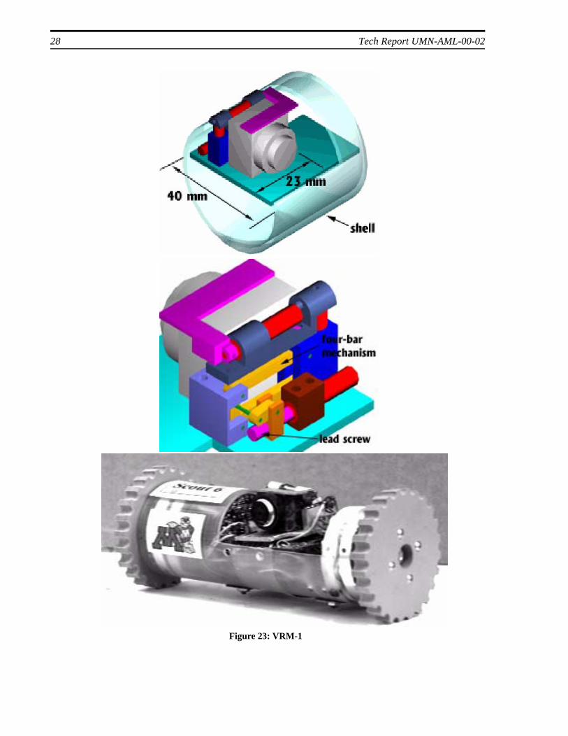
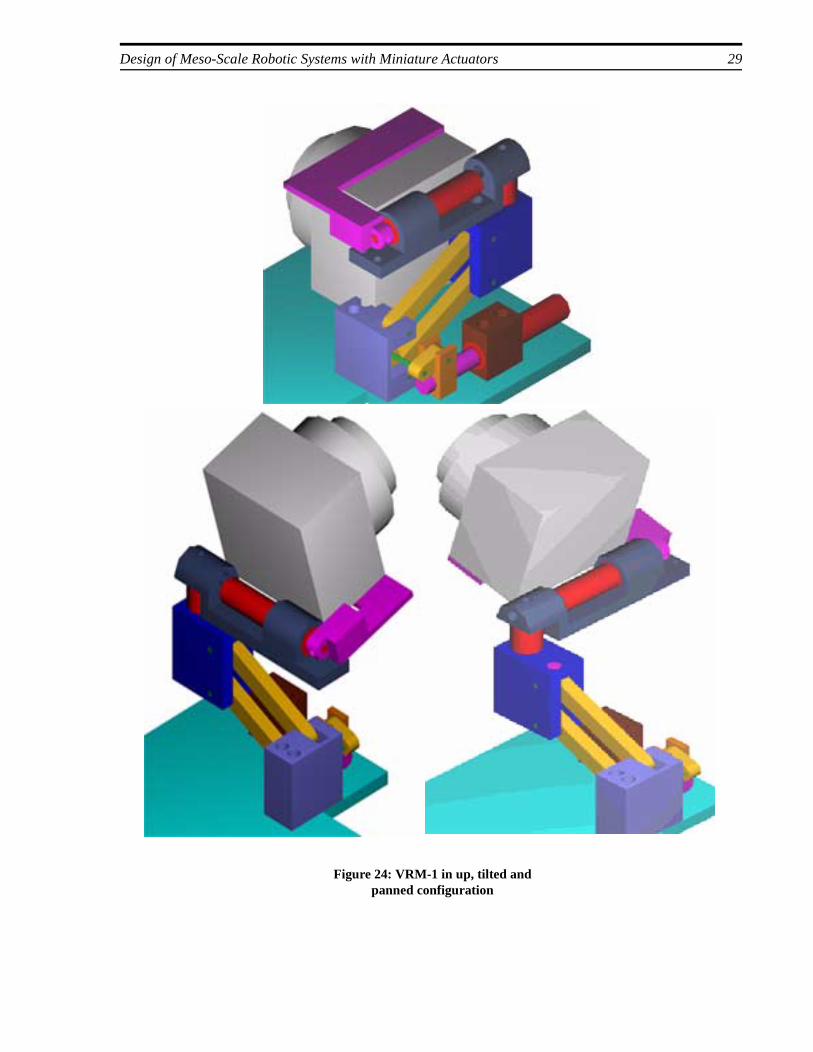
Figure 23 illustrates the pan/tilt/pop-up mechanism of VRM-1. Three miniature electric motors areused. The tilt motor is directly coupled to the camera, and the pan motor carries the camera and thetilt motor. A third motor is coupled to a leadscrew that is used to operate a four-bar mechanism.The parallel four-bar mechanism moves the camera and the other two motors up and down. Figure24 shows the up (deployed), tilted and panned states. Before deployment, the robot rolls itself ~150degrees to face the camera side up (see Figure 20) Note that the first 90 degrees of tilt is necessaryto clear the camera out of the shell. The remaining 90 degrees of tilt rotation, together with the 180degree pan, provides a hemispherical field of view.
5.3.2 Driver electronics
As mentioned earlier, the Smoovy motor is a brushless dc design that has no sensors for feedback.A common method used for commutation of sensorless motors is back-emf sensing. In this method,the motor phases (windings) are commutated such that one phase is left energized at each commu-tation cycle. Due to the rotation of the magnetic rotor, a sinusoidal voltage is induced across thiscoil (back emf). This voltage is tracked by driver circuitry for its zero crossing and motor windingsare energized in correct timing [18]. A commercial integrated circuit is available that combinesback-emf sensing and driving circuitry in a single package [18]. However, back emf produced bythe small windings of the Smoovy motor is not sufficient for correct operation of this circuit [21].
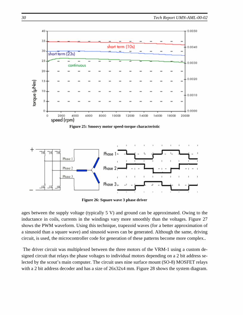
Therefore only choice left is sensorless, open loop commutation. In this mode, the motor is usedessentially as an AC synchronous motor. In AC synchronous motors, the three phase voltage is ap-plied to the windings to create a magnetic field that rotates at the supply frequency. The rotor fol-lows this field at the same frequency and displays a constant speed-torque characteristic within itsload range. The speed drops abruptly when the maximum load capability is exceeded since the ro-tor is no longer synchronous with the field. Figure 25 shows the flat speed-torque characteristic ofthe 3 mm Smoovy motor (without the gearbox) when driven with 3 phase ac supply [20].
A commercial driver circuit supplied by the Smoovy company (model CPS00002) was used fordriving the motors on VRM-1 [22]. This microprocessor controlled circuit creates square wave pat-terns that approximate the 3 phase (120 degree) sinusoidal voltage supply to an AC motor. The fre-quency is adjustable for speed control. The circuit board is 20x30x5 mm in size. Figure 26 showsa simplified driver schematic and phase voltages during a single cycle.
When square waves are used instead of sinusoids, torque ripple may be observed, especially at lowspeeds [12]. However, generating sinusoidal waves at variable frequency requires more complexcircuitry compared to the simple on/off operation of a square wave driver. An alternative methodis pulse width modulation (PWM) where the duty cycle (time-on/total cycle time) of the squarewave is changed. This results in an average voltage proportional to the duty cycle, and, thus, volt-
28 Tech Report UMN-AML-00-02
Figure 23: VRM-1
Design of Meso-Scale Robotic Systems with Miniature Actuators 29
Figure 24: VRM-1 in up, tilted and panned configuration
30 Tech Report UMN-AML-00-02
relaysiagram.
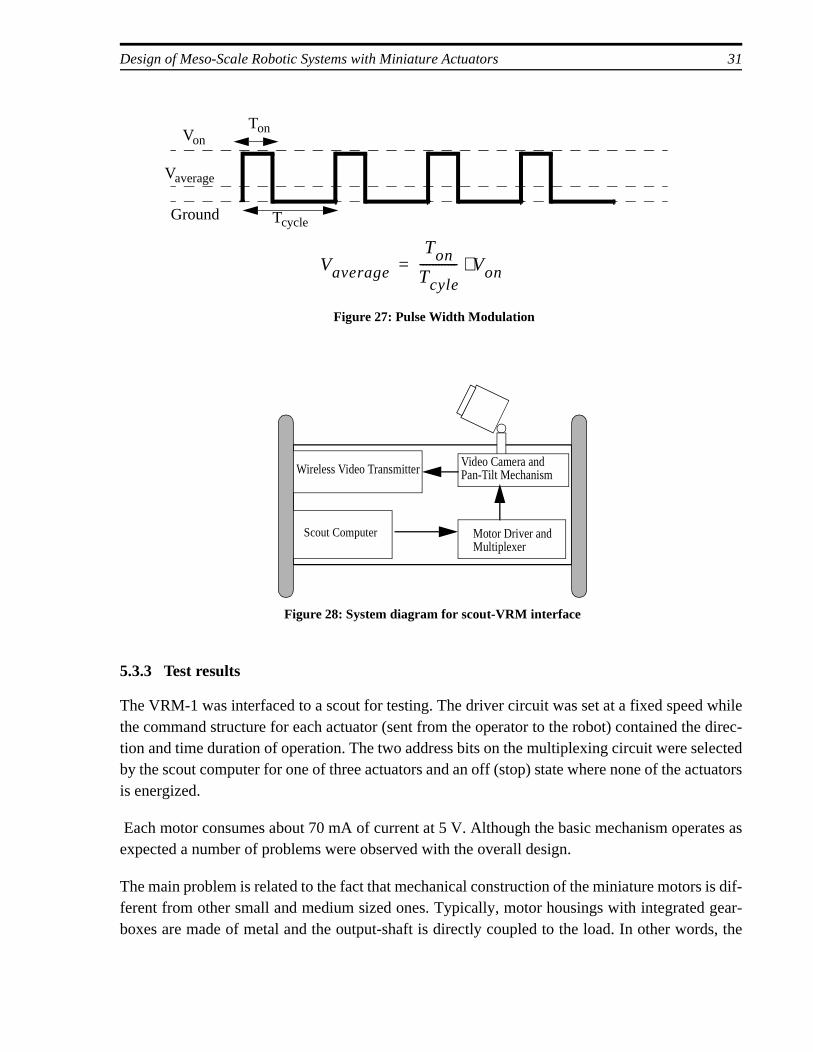
ages between the supply voltage (typically 5 V) and ground can be approximated. Owing to theinductance in coils, currents in the windings vary more smoothly than the voltages. Figure 27shows the PWM waveform. Using this technique, trapezoid waves (for a better approximation ofa sinusoid than a square wave) and sinusoid waves can be generated. Although the same, drivingcircuit, is used, the microcontroller code for generation of these patterns become more complex..
The driver circuit was multiplexed between the three motors of the VRM-1 using a custom de-signed circuit that relays the phase voltages to individual motors depending on a 2 bit address se-lected by the scout’s main computer. The circuit uses nine surface mount (SO-8) MOSFETwith a 2 bit address decoder and has a size of 26x32x4 mm. Figure 28 shows the system d
Figure 25: Smoovy motor speed-torque characteristic
Figure 26: Square wave 3 phase driver
Design of Meso-Scale Robotic Systems with Miniature Actuators 31
5.3.3 Test results
The VRM-1 was interfaced to a scout for testing. The driver circuit was set at a fixed speed whilethe command structure for each actuator (sent from the operator to the robot) contained the direc-tion and time duration of operation. The two address bits on the multiplexing circuit were selectedby the scout computer for one of three actuators and an off (stop) state where none of the actuatorsis energized.
Each motor consumes about 70 mA of current at 5 V. Although the basic mechanism operates asexpected a number of problems were observed with the overall design.
The main problem is related to the fact that mechanical construction of the miniature motors is dif-ferent from other small and medium sized ones. Typically, motor housings with integrated gear-boxes are made of metal and the output-shaft is directly coupled to the load. In other words, the
Von
Ground
Ton
Tcycle
Vaverage
Vaverage
Ton
Tcyle------------ Von⋅=
Figure 27: Pulse Width Modulation
Wireless Video TransmitterVideo Camera and
Scout Computer Motor Driver and
Pan-Tilt Mechanism
Multiplexer
Figure 28: System diagram for scout-VRM interface
32 Tech Report UMN-AML-00-02
gearbox design is made to account for increased load at the output shaft. In case of the Smoovymotor, the gearbox housing is made of a plastic material and is lightly fitted on the motor housing(see Figure 22). Although the gearbox is specified to carry 40 N axial and 25 N radial load [23] thehousing is not able to take any axial load without dismounting from the motor. This was observedeven during careful assembly of the mechanism. However, the VRM-1 design does not have anymeans for protecting the motors from radial and axial loads since their specifications were far be-yond anticipated loads on them.
A similar problem exists with the tube shaped plastic housing that also has internal threads to serveas the outer ring gear for the planetary gear system. Since the motor has no special means formounting (i.e. bolt threads at the faceplate), a tight fit mount was used for VRM-1. However, theflexible outer housing squeezes the planetary gears and inteferes with the operation of the gearbox.
The large size of the driver electronics was another problem with the VRM-1. In fact, the springarm winder mechanism on the prototype scout used for VRM-1 testing was removed to allow spacefor driver circuitry. Since small sized surface mount components were already used, the only wayto reduce the size of electronics is to reduce the number of motors. This requires coupling of dif-ferent motions (i.e. tilt and deploy/retract) or mechanical multiplexing of an actuator between oneor more actions.
The fixed operation speed of the driver circuit was found to be inadequate for control of differentactuators. For example, the deploy/retract motor uses a screw drive with a large reduction in speedwhile others are directly coupled. The driver speed was set at a value suitable for directly coupledactuators (pan and tilt) which resulted in very slow action of the four-bar mechanism.
5.4 Second Generation Video Reconnaissance Module (VRM-2)
The experience gained from VRM-1 was used in the design of second generation video reconnais-sance module to solve the problems encountered with the first one.
5.4.1 Mechanical design
A design with a reduced number of actuators, and thus electronics, was sought for VRM-2. Addi-tionally, all motors were coupled by bearings for protection from axial loads.
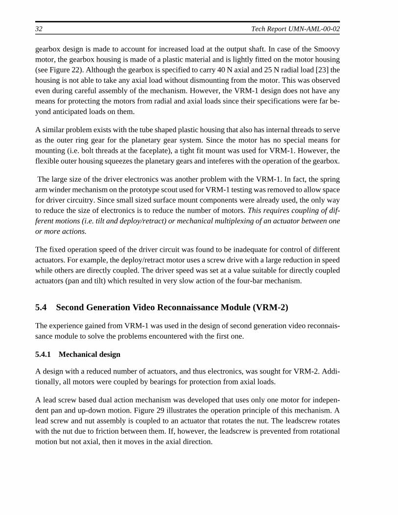
A lead screw based dual action mechanism was developed that uses only one motor for indepen-dent pan and up-down motion. Figure 29 illustrates the operation principle of this mechanism. Alead screw and nut assembly is coupled to an actuator that rotates the nut. The leadscrew rotateswith the nut due to friction between them. If, however, the leadscrew is prevented from rotationalmotion but not axial, then it moves in the axial direction.
Design of Meso-Scale Robotic Systems with Miniature Actuators 33
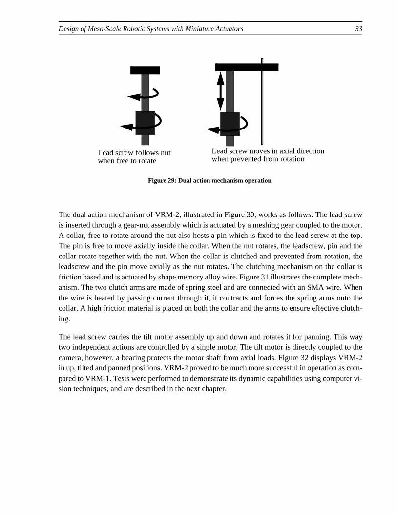
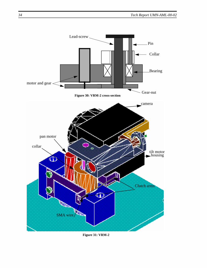
The dual action mechanism of VRM-2, illustrated in Figure 30, works as follows. The lead screwis inserted through a gear-nut assembly which is actuated by a meshing gear coupled to the motor.A collar, free to rotate around the nut also hosts a pin which is fixed to the lead screw at the top.The pin is free to move axially inside the collar. When the nut rotates, the leadscrew, pin and thecollar rotate together with the nut. When the collar is clutched and prevented from rotation, theleadscrew and the pin move axially as the nut rotates. The clutching mechanism on the collar isfriction based and is actuated by shape memory alloy wire. Figure 31 illustrates the complete mech-anism. The two clutch arms are made of spring steel and are connected with an SMA wire. Whenthe wire is heated by passing current through it, it contracts and forces the spring arms onto thecollar. A high friction material is placed on both the collar and the arms to ensure effective clutch-ing.
The lead screw carries the tilt motor assembly up and down and rotates it for panning. This waytwo independent actions are controlled by a single motor. The tilt motor is directly coupled to thecamera, however, a bearing protects the motor shaft from axial loads. Figure 32 displays VRM-2in up, tilted and panned positions. VRM-2 proved to be much more successful in operation as com-pared to VRM-1. Tests were performed to demonstrate its dynamic capabilities using computer vi-sion techniques, and are described in the next chapter.
Lead screw follows nut Lead screw moves in axial directionwhen prevented from rotation
Figure 29: Dual action mechanism operation
when free to rotate
34 Tech Report UMN-AML-00-02
Gear-nut
motor and gear
Lead-screw
Collar
Pin
Bearing
Figure 30: VRM-2 cross-section
Clutch arms
pan motor
collartilt motorhousing
camera
SMA wire
Figure 31: VRM-2

Design of Meso-Scale Robotic Systems with Miniature Actuators 35
Figure 32: VRM-2 up, tilted and panned
36 Tech Report UMN-AML-00-02
6. Active Vision with the Video Module
It is essential for a distributed robotic system to exhibit some degree of autonomous behavior, es-pecially when the number of robots is high compared to the number of operators. Although the ba-sic functionality of the video reconnaissance module is to increase the effective field of view of thecamera, it is also desirable to implement computer vision techniques to aid in autonomous andsemi-autonomous surveillance.
Active vision is a field of computer vision in which the camera is able to move under control, as inthe case of the pan-tilt video reconnaissance module. Some of the common application areas of ac-tive vision are robotic systems for object manipulation, mobile systems and surveillance. Imple-menting active vision techniques with a system like the VRM that has miniature actuators and aunique structure presents its own challenges. This chapter discusses these challenges and presentsan implementation of autonomous motion detection and tracking with the VRM.
6.1 Experimental set-up
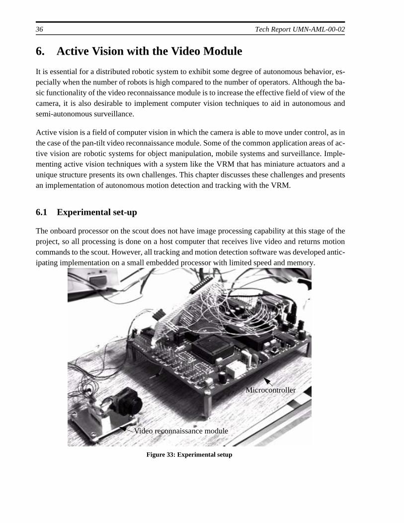
The onboard processor on the scout does not have image processing capability at this stage of theproject, so all processing is done on a host computer that receives live video and returns motioncommands to the scout. However, all tracking and motion detection software was developed antic-ipating implementation on a small embedded processor with limited speed and memory.
Figure 33: Experimental setup
Video reconnaissance module
Microcontroller
Design of Meso-Scale Robotic Systems with Miniature Actuators 37
g sys-ideo iso the mi-dingly.
he pro-GUI. Ats dy-
as im- is that
en suc-en itsof
theted for
t of the by theed po-
do notres withls. Thee . Aplace-neously
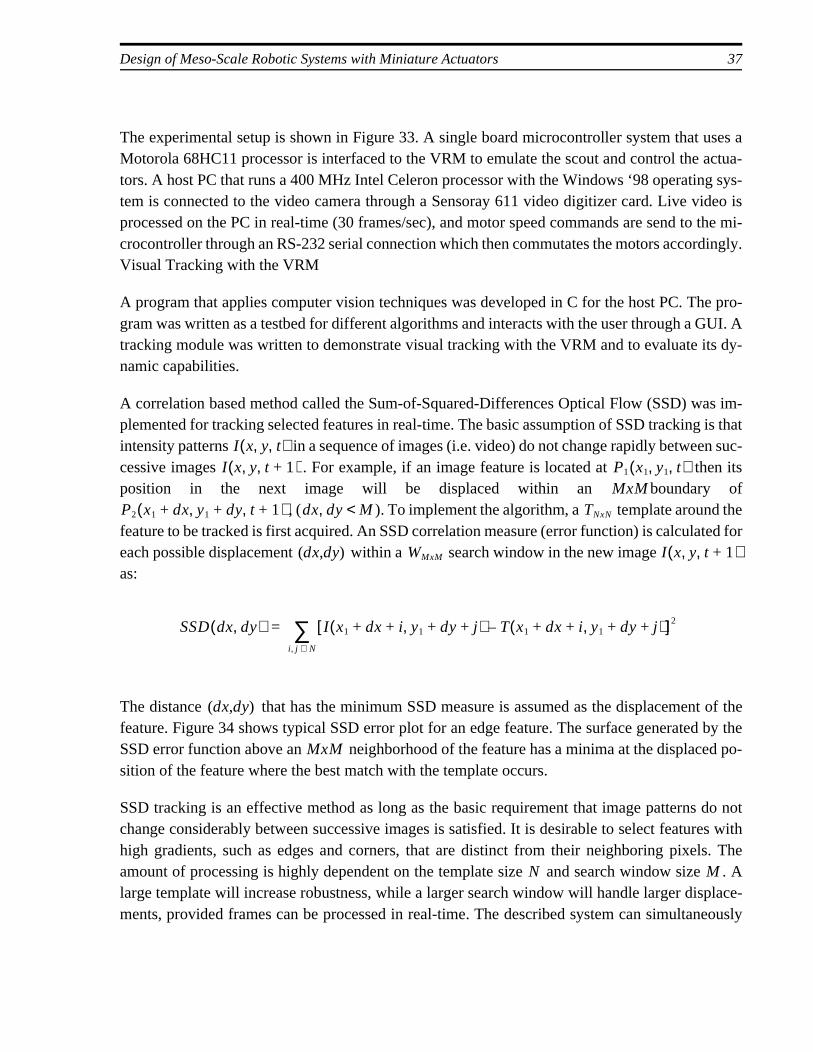
The experimental setup is shown in Figure 33. A single board microcontroller system that uses aMotorola 68HC11 processor is interfaced to the VRM to emulate the scout and control the actua-tors. A host PC that runs a 400 MHz Intel Celeron processor with the Windows ‘98 operatintem is connected to the video camera through a Sensoray 611 video digitizer card. Live vprocessed on the PC in real-time (30 frames/sec), and motor speed commands are send tcrocontroller through an RS-232 serial connection which then commutates the motors accorVisual Tracking with the VRM
A program that applies computer vision techniques was developed in C for the host PC. Tgram was written as a testbed for different algorithms and interacts with the user through a tracking module was written to demonstrate visual tracking with the VRM and to evaluate inamic capabilities.
A correlation based method called the Sum-of-Squared-Differences Optical Flow (SSD) wplemented for tracking selected features in real-time. The basic assumption of SSD trackingintensity patterns in a sequence of images (i.e. video) do not change rapidly betwecessive images . For example, if an image feature is located at thposition in the next image will be displaced within an boundary
, ( ). To implement the algorithm, a template around feature to be tracked is first acquired. An SSD correlation measure (error function) is calculaeach possible displacement within a search window in the new image as:
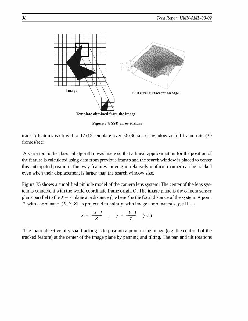
The distance that has the minimum SSD measure is assumed as the displacemenfeature. Figure 34 shows typical SSD error plot for an edge feature. The surface generatedSSD error function above an neighborhood of the feature has a minima at the displacsition of the feature where the best match with the template occurs.
SSD tracking is an effective method as long as the basic requirement that image patternschange considerably between successive images is satisfied. It is desirable to select featuhigh gradients, such as edges and corners, that are distinct from their neighboring pixeamount of processing is highly dependent on the template size and search window sizlarge template will increase robustness, while a larger search window will handle larger disments, provided frames can be processed in real-time. The described system can simulta
I x y t, ,( )I x y t 1+, ,( ) P1 x1 y1 t, ,( )
MxMP2 x1 dx+ y1 dy+ t 1+, ,( ) dx dy, M< TNxN
dx dy( , ) WMxM I x y t 1+, ,( )
SSD dx dy,( ) I x1 dx i y1 dy j+ +,+ +( ) T x1 dx i y1 dy j+ +,+ +( )–[ ]2
i j, N∈∑=
dx dy( , )
MxM
N M
38 Tech Report UMN-AML-00-02
track 5 features each with a 12x12 template over 36x36 search window at full frame rate (30frames/sec).
A variation to the classical algorithm was made so that a linear approximation for the position ofthe feature is calculated using data from previous frames and the search window is placed to centerthis anticipated position. This way features moving in relatively uniform manner can be trackedeven when their displacement is larger than the search window size.
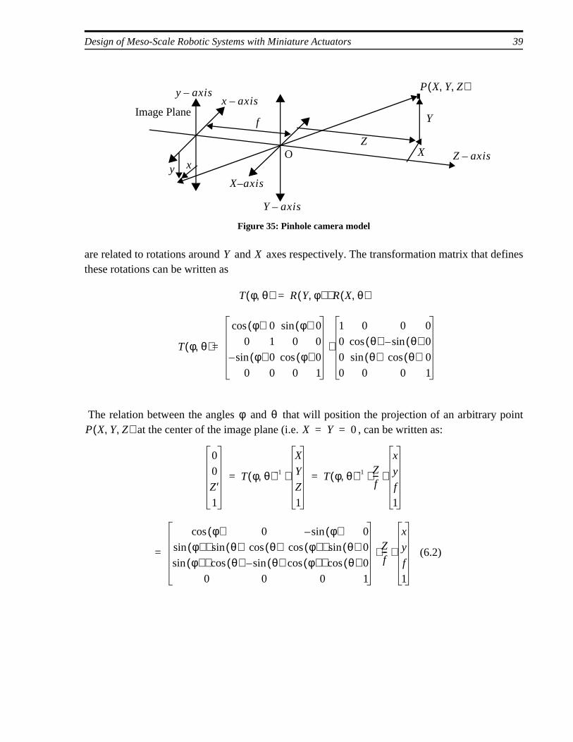
Figure 35 shows a simplified pinhole model of the camera lens system. The center of the lens sys-tem is coincident with the world coordinate frame origin O. The image plane is the camera sensorplane parallel to the plane at a distance , where is the focal distance of the system. A point
with coordinates is projected to point with image coordinates as
The main objective of visual tracking is to position a point in the image (e.g. the centroid of thetracked feature) at the center of the image plane by panning and tilting. The pan and tilt rotations
SSD error surface for an edge
Template obtained from the image
Image
Figure 34: SSD error surface
X Y– f fP X Y Z, ,( ) p x y z ), ,( )
xX– f⋅Z
------------- , yY– f⋅Z
------------ (6.1)= =
Design of Meso-Scale Robotic Systems with Miniature Actuators 39
are related to rotations around and axes respectively. The transformation matrix that definesthese rotations can be written as
The relation between the angles and that will position the projection of an arbitrary point at the center of the image plane (i.e. , can be written as:
O
Figure 35: Pinhole camera model
P X Y Z, ,( )
Y axis–
X axis–
Z axis–
Y
XZ
x axis–y axis–
f
xy
Image Plane
Y X
T φ θ,( ) R Y φ,( ) R X θ,( )⋅=
T φ θ,( )
φ( )cos 0 φ( )sin 0
0 1 0 0
φ( )sin– 0 φ( )cos 0
0 0 0 1
=
1 0 0 0
0 θ( )cos θ( )sin– 0
0 θ( )sin θ( )cos 0
0 0 0 1
⋅
φ θP X Y Z, ,( ) X Y 0= =
0
0
Z′1
T φ θ,( ) 1–
X
Y
Z
1
⋅ T φ θ,( ) 1– Zf---
x
y
f
1
⋅ ⋅= =
φ( )cos 0 φ( )sin– 0
φ( )sin θ( )sin⋅ θ( )cos φ( )cos θ( )sin⋅ 0
φ( )sin θ( )cos⋅ θ( )sin– φ( )cos θ( )cos⋅ 0
0 0 0 1
Zf---
x
y
f
1
(6.2)⋅ ⋅=
40 Tech Report UMN-AML-00-02
Solving (6.2)
From (6.3) it is clear that the pan and tilt angles are only a function of the known and measurablevariables , and . Additionally, the coordinate of an image point is effected by both pan andtilt whereas the coordinate is controlled only by the pan angle .
All visual servoing experiments were performed with the control of the pan angle only, the tilt an-gle being fixed. Therefore, the aim of the controller was to the fixate the coordinate of the targetpoint at zero.
The relation between and can be rewritten as
where [mm/pixel] is the physical distance in the direction (width) per each individual pixelon the sensor plane and is the coordinate in pixels, which is the actual measured variable. Forthe case where is small (i.e. when the tracking system is closely following the target), the relationbetween pan speed (rad/sec) and image velocity can be approximated as
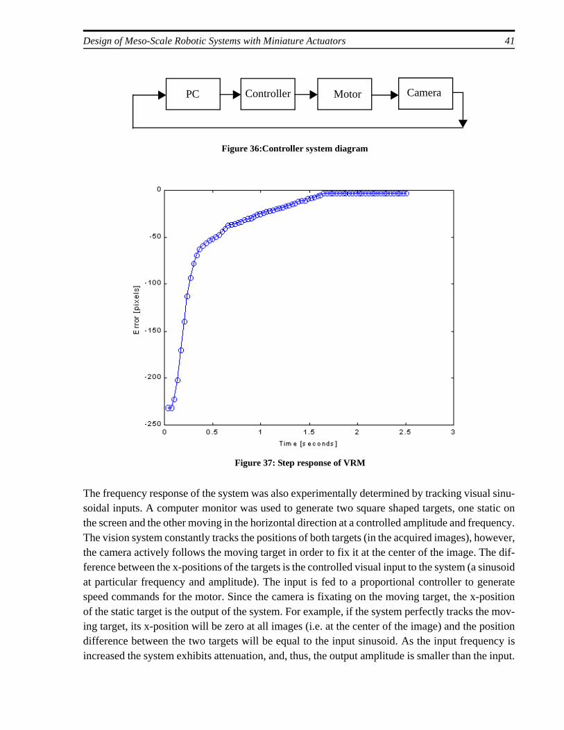
The constant has been experimentally determined to be 0.00145 for the VRM camera. A pro-portional controller was used to generate the speed commands for the motor and the gain was ad-justed manually. A target feature to be tracked is visually selected by the user, and its grayscalepattern is stored in a template. The position error is calculated at every frame and a corresponding8 bit speed value is send to the microcontroller through the serial interface. The commanded speedof the actuator ranges between 0.05 and 1.32 rps at 0.01 rps intervals in both directions. The lowerbound on commanded speed was experimentally found to be the lowest value that the actuator ro-tates without significant torque ripple. Figure 36 shows the closed loop controller diagram. Figure37 shows the step response of the controller while tracking a stationary target.
x φ( )cos f φ( )sin– 0=
x φ( )sin θ( )sin y θ( )cos f φ( )sin θ( )cos+ + 0=
φ xf--
(6.3)atan=
θ y–x φ( )sin f φ( )cos+--------------------------------------------
atan=
x y f yx φ
x
x φ
φ( )tanxf--
sx px⋅f
------------- (6.4)= =
sx xpx x
φ
φ 0 φ( )tan⇒ φ≈ ≈
φ· K px·
(6.5)⋅=
K
Design of Meso-Scale Robotic Systems with Miniature Actuators 41
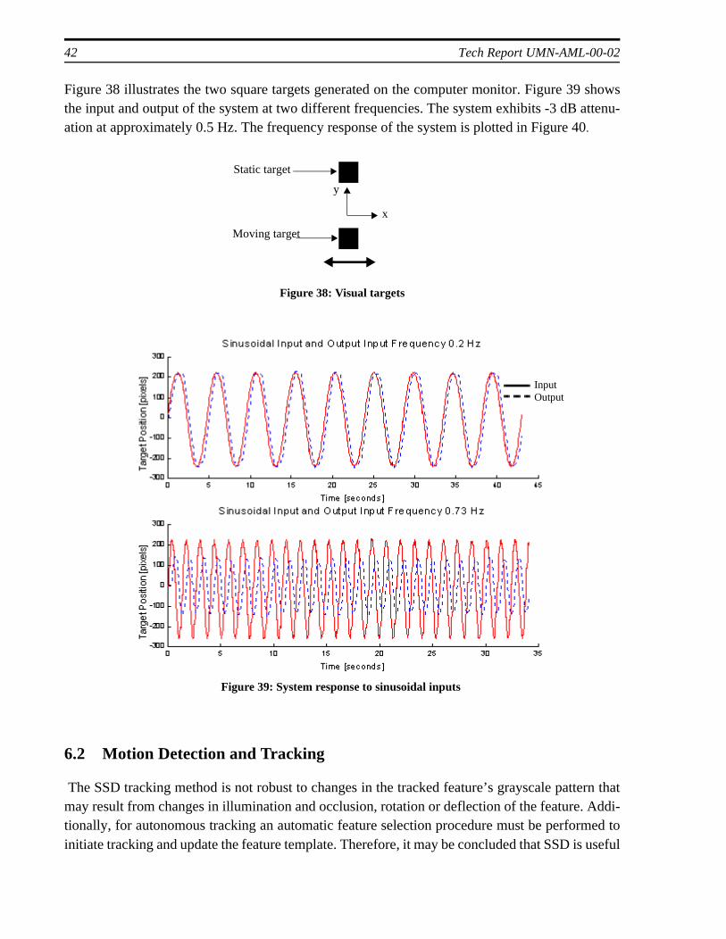
The frequency response of the system was also experimentally determined by tracking visual sinu-soidal inputs. A computer monitor was used to generate two square shaped targets, one static onthe screen and the other moving in the horizontal direction at a controlled amplitude and frequency.The vision system constantly tracks the positions of both targets (in the acquired images), however,the camera actively follows the moving target in order to fix it at the center of the image. The dif-ference between the x-positions of the targets is the controlled visual input to the system (a sinusoidat particular frequency and amplitude). The input is fed to a proportional controller to generatespeed commands for the motor. Since the camera is fixating on the moving target, the x-positionof the static target is the output of the system. For example, if the system perfectly tracks the mov-ing target, its x-position will be zero at all images (i.e. at the center of the image) and the positiondifference between the two targets will be equal to the input sinusoid. As the input frequency isincreased the system exhibits attenuation, and, thus, the output amplitude is smaller than the input.
Controller Motor CameraPC
Figure 36:Controller system diagram
Figure 37: Step response of VRM
42 Tech Report UMN-AML-00-02
ern thatAddi-med to useful
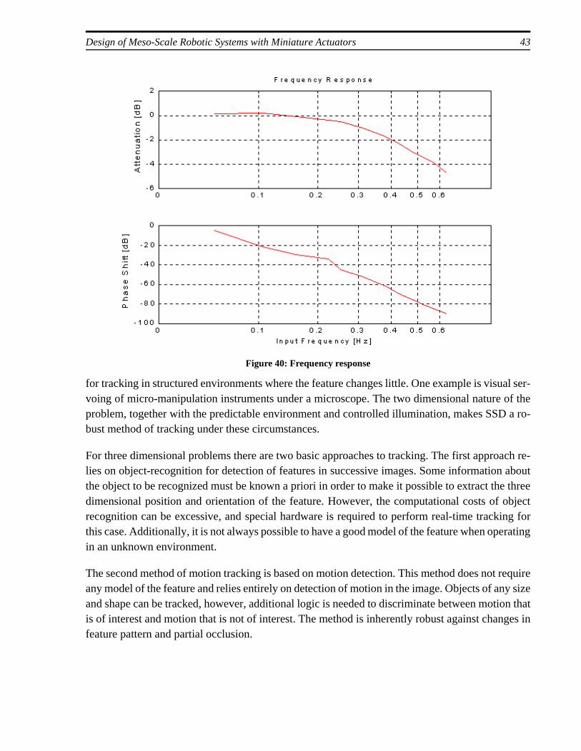
Figure 38 illustrates the two square targets generated on the computer monitor. Figure 39 showsthe input and output of the system at two different frequencies. The system exhibits -3 dB attenu-ation at approximately 0.5 Hz. The frequency response of the system is plotted in Figure 40.
6.2 Motion Detection and Tracking
The SSD tracking method is not robust to changes in the tracked feature’s grayscale pattmay result from changes in illumination and occlusion, rotation or deflection of the feature. tionally, for autonomous tracking an automatic feature selection procedure must be perforinitiate tracking and update the feature template. Therefore, it may be concluded that SSD is
y
x
Static target
Moving target
Figure 38: Visual targets
Figure 39: System response to sinusoidal inputs
InputOutput
Design of Meso-Scale Robotic Systems with Miniature Actuators 43
for tracking in structured environments where the feature changes little. One example is visual ser-voing of micro-manipulation instruments under a microscope. The two dimensional nature of theproblem, together with the predictable environment and controlled illumination, makes SSD a ro-bust method of tracking under these circumstances.
For three dimensional problems there are two basic approaches to tracking. The first approach re-lies on object-recognition for detection of features in successive images. Some information aboutthe object to be recognized must be known a priori in order to make it possible to extract the threedimensional position and orientation of the feature. However, the computational costs of objectrecognition can be excessive, and special hardware is required to perform real-time tracking forthis case. Additionally, it is not always possible to have a good model of the feature when operatingin an unknown environment.
The second method of motion tracking is based on motion detection. This method does not requireany model of the feature and relies entirely on detection of motion in the image. Objects of any sizeand shape can be tracked, however, additional logic is needed to discriminate between motion thatis of interest and motion that is not of interest. The method is inherently robust against changes infeature pattern and partial occlusion.
Figure 40: Frequency response

44 Tech Report UMN-AML-00-02
t withe scout
Two basic approaches to motion detection are optical flow [24] and motion-energy [17] methods.Optical flow methods, under which the SSD algorithm can be classified, find the velocity field inthe image by solving the equation:
where is the image function, and are velocity functions thatare being sought. Since there are two unknowns but one equation, additional constraints such assmoothness are needed for a unique solution. Once the velocity field is found, regions of motionare extracted and tracked. Motion-energy methods, on the other hand, find the temporal derivativeof the entire image and threshold it to extract regions of motion. The temporal derivative is usuallyfound by simple image substraction
This information is usually imprecise and subject to noise. Adding spatial gradient information,such as incorporating edge strength as a multiplier before thresholding, is a frequently appliedmethod of improvement [17]. However, these additions increase complexity and computationalcosts.
With all methods of motion detection and tracking, an additional problem is introduced with theactive camera. Egomotion, or the induced motion in the image due to the motion of the camera it-self, must be discriminated from actual motion in the view. Optical flow methods of motion detec-tion use some form of smoothness constraint to solve this problem. Once the gross velocity fieldof the image, which represents the egomotion, is found, pixels that belong to the same feature butare displaced between consecutive images due to egomotion are re-mapped with a process calledregistration. When the registered images are compared (i.e. subtracted), regions of actual motionare extracted. Again, this method is subject to noise just as with simple image substraction.
Another method of registration uses position sensor feedback (i.e. encoders on the pan-tilt cameraaxes) to cancel the effects of camera motion. The method relies on the accuracy of the sensory dataand good calibration of the camera [19].
A method of motion detection and tracking that is suitable for the mechanical and anticipated com-putational capabilities of the VRM is needed. One application of such an algorithm would be to usethe scout in an autonomous “watchdog” mode where it continuously monitors its environmenthe video camera, detects, and then tracks motion (e.g. people walking into a room where th
x∂∂f
ux∂
∂fv
t∂∂f
+⋅+⋅ 0=
f x y t, ,( ) u x y,( )td
dx= v x y,( )
tddy
=
tdd f x y t, ,( ) f x y t, ,( ) f x y t ∇t+, ,( )–
∇t----------------------------------------------------------≈
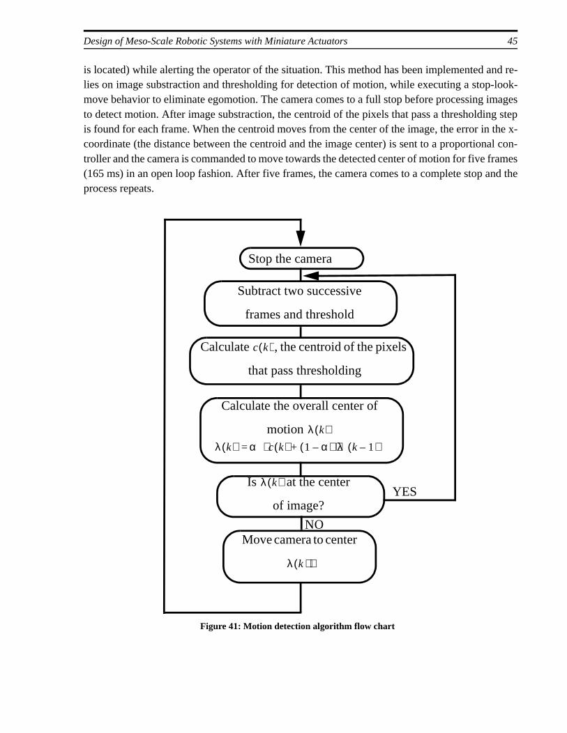
Design of Meso-Scale Robotic Systems with Miniature Actuators 45
is located) while alerting the operator of the situation. This method has been implemented and re-lies on image substraction and thresholding for detection of motion, while executing a stop-look-move behavior to eliminate egomotion. The camera comes to a full stop before processing imagesto detect motion. After image substraction, the centroid of the pixels that pass a thresholding stepis found for each frame. When the centroid moves from the center of the image, the error in the x-coordinate (the distance between the centroid and the image center) is sent to a proportional con-troller and the camera is commanded to move towards the detected center of motion for five frames(165 ms) in an open loop fashion. After five frames, the camera comes to a complete stop and theprocess repeats.
Stop the camera
Calculate the overall center of
motion λ k( )
Subtract two successive
frames and threshold
λ k( ) α c k( ) 1 α–( ) λ k 1–( )⋅+⋅=
Calculate , the centroid of the pixels
that pass thresholding
c k( )
Is at the center
of image?
λ k( )
Move camera to center
λ k )( )
Figure 41: Motion detection algorithm flow chart
YES
NO
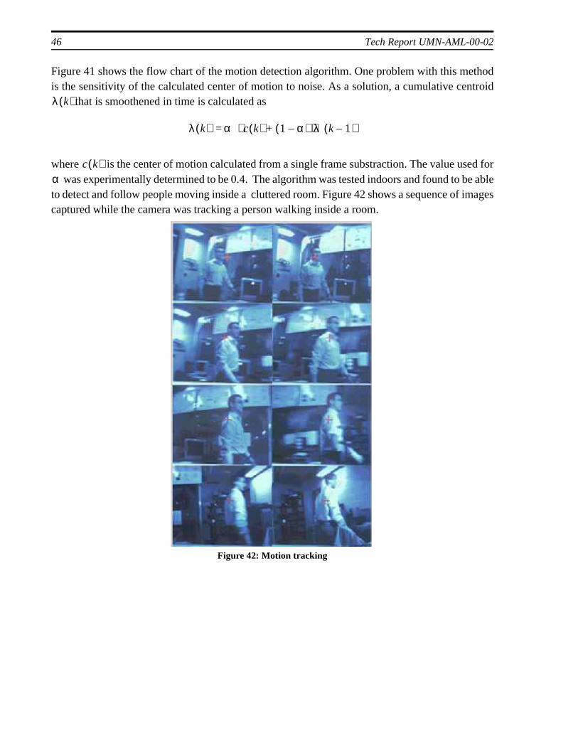
46 Tech Report UMN-AML-00-02
Figure 41 shows the flow chart of the motion detection algorithm. One problem with this methodis the sensitivity of the calculated center of motion to noise. As a solution, a cumulative centroid
that is smoothened in time is calculated as
where is the center of motion calculated from a single frame substraction. The value used for was experimentally determined to be 0.4. The algorithm was tested indoors and found to be able
to detect and follow people moving inside a cluttered room. Figure 42 shows a sequence of imagescaptured while the camera was tracking a person walking inside a room.
λ k( )
λ k( ) α c k( ) 1 α–( ) λ k 1–( )⋅+⋅=
c k( )α
Figure 42: Motion tracking
Design of Meso-Scale Robotic Systems with Miniature Actuators 47
7. Conclusion
In this report, the design of small scaled robotic systems with miniature actuators was discussed.A pan-tilt video camera system was designed for a miniature mobile robot to comply with volumeand power restrictions on the robot.
Video sensor and wireless transmitter technologies were summarized. CMOS type video sensorswere found superior to the common CCD type for miniature applications due to their much smallersize and power consumption. A single-chip CMOS sensor and a miniature wireless transmitter op-erating at 900 MHz were chosen for the video camera system.
Three main actuation technologies that are suitable for miniature applications from millimeter tocentimeter size were discussed with an emphasis on their advantages and disadvantages for mobilesystems. Shape memory alloy actuators were found useful for simple on-off type actuation withoutposition control due to their simplicity and robustness. However, their slow response time is an is-sue. Piezoelectric actuators, on the other hand, have the fastest response of all but require high volt-age and more complex drive electronics when compared to other actuation technologies. Thetorque output of an electromagnetic actuator was shown to decrease by the cube of the linear di-mension making them unsuitable for miniaturization in general, however they were still found tobe the most suitable type for the application due to their availability, small drive electronics andease of control.
Miniature electric motors available on the market were compared and a 3 mm diameter brushlessPM motor with a 125:1 integrated gearbox was chosen. Alternative designs were presented andspecial issues for machines that use these motors were discussed. A special mechanism to use onemotor for two independent actions were developed to reduce the number of necessary electronics.Motor driver electronics were developed for brushless, sensorless operation of these motors.
Finally, computer vision techniques were applied to demonstrate and evaluate the capabilities ofthe system. Lacking position sensors, the system relies on visual information for orientation con-trol. Visual tracking with the SSD technique was demonstrated and system response to step andsinusoidal inputs were plotted. Additionally, a simple motion detection and tracking algorithmsuitable for mechanical and computational capabilities of the system was developed.
Future goals for the video reconnaissance module include on-board image processing, integrationof sensory components for camera orientation feedback and development of better mechanisms forfurther reduction in the number of actuators.
Miniature actuator technology is still in its early stages. As more and better actuators become avail-able, the number of applications that employ them will increase. The absence of standard, off-the-shelf drive components of comparable size is a current drawback of using miniature actuators.Common components like gears, flexible shaft couplings or clutches are still needed in meso-scale

48 Tech Report UMN-AML-00-02
robotic systems. Further reduction of the size of drive electronics and sensors is also needed forthis field. The technology for miniaturization of drive electronics to a size comparable with minia-ture actuators already exists, however, more commercial applications for miniature actuators areneeded in order to push the development of this technology further.
Design of Meso-Scale Robotic Systems with Miniature Actuators 49
riald-
ed by
yc-
nc.,
D. G.oyles
o”,
8. References
[1] J. Conrad, J. Mills, Stiquito Advanced Experiments with a Simple and Inexpensive Robot, IEEE Com-puter Society,1998.
[2] A. Cox, E. Garcia, M. Goldfarb, “Actuator Development for a Flapping Microrobotic MicroaeVehicle”, Microrobotics and Micromanipulation, A. Sulzman and B.J. Nelson, Editors, Proceeings of SPIE Vol. 3519, pp. 102-108, 1998.
[3] K. Deng, A. Dewa, D. Ritter, C. Bonham, H. Guckel, “Characterization of Gear Pumps FabricatLIGA”, Microsystem Technologies, Vol.4, No.4, pp.163-167, 1998.
[4] P. Denyer, “CMOS vs. CCD”, whitepaper by Vision Company, UK, 1999, “www.vvl.co.uk/whmos/whitepaper.htm”.
[5] M. Dornheim, “Tiny Drones May be Soldier’s New Tool”, Aviation Week & Space Technology, pp.42-48, June 8 1998.
[6] K. Gabriel, W. Trimmer, J. Walker, “A Micro Rotary Actuator Using Shape Memory Alloys”, Sen-sors & Actuators, Vol. 15,No.1, pp. 95-102, 1988.
[7] B. Grob, Basic Television and Video Systems, McGrawHill,1999.
[8] D. Hanselman, Brushless Permanent-magnet Motor Design, McGraw-Hill,1994
[9] D. E. Hodgson, M. H. Wu, R. J. Biermann, “Shape Memory Alloys” , whitepaper by SMA-Ihttp://www.sma-inc.com/SMAPaper.html
[10] D. F. Hougen, S. Benjaafar, J. C. Bonney, J. R. Budenske, M. Dvorak, M. Gini, H. French, Krantz, P. Y. Li, F. Malver, B. Nelson, N. Papanikolopoulos, P. E. Rybski, S. A. Stoeter, R. Vand K.B. Yesin, ”A Miniature Robotic System for Reconnaissance and Surveillance”, IEEE Inter-national Conference on Robotics and Automation (ICRA2000), 2000.
[11] H. Ishihara, F. Arai, T. Fukuda, “Micro Mechatronics and Micro Actuators”, IEEE/ASME Transac-tions on Mechatronics, Vol. 1, No. 1, pp. 68-79, 1996.
[12] T. Kenjo, Power Electronics for the Microprocessor Age, Oxford University Press, 1990.
[13] G. Kovacs, Micromachined Transducers Handbook, McGrawHill, 1998.
[14] A. Lipton, H. Fujiyoshi, R. Patil, “Moving Target Classification and Tracking from Real-time VideIEEE Workshop on Applications of Computer Vision (WACV), pp.8-14, 1998.
[15] MicroMo Company Catalog, USA, 1997.
[16] R. Moroney, R. White, R. Howe, “Ultrasonic Micromotors: Physics and Applications”, IEEE MicroElectro Mechanical Systems An Investigation of Micro Structures, Sensors, Actuators, Machinesand Robots, IEEE, pp. 182-187, 1990.
[17] D. Murray, A. Basu, “Motion Tracking with an Active Camera”, IEEE Transactions on Pattern Anal-ysis and Machine Intelligence, Vol. 16, No. 5, pp. 449-459, 1994.
[18] Phillips Semiconductor product data sheet, TDA5140A Brushless DC Motor Drive Circuit, April1994.
[19] Physic Instrumente Company Catalog, “NanoPositionning”, Germany, 1999.
[20] RMB Smoovy product data sheet, SYH39001 High Precision Motor 3 mm, February 1999.
[21] RMB Smoovy product Application Notes, CCS00001 Controller, November 1998.
50 Tech Report UMN-AML-00-02
ion”,PIE
[22] RMB Smoovy product data sheet, CPS00002 Controller, November 1998.
[23] RMB Smoovy product data sheet, SPH39003 3mm Gearmotor, February 1999.
[24] G. Whitten, “Independent Motion Target Cueing for Moving Sensor Systems”, Applications of Arti-ficial Intelligence VI, Proceedings of SPIE Vol. 937, pp. 336-341, 1988.
[25] Y. Zhou, B.J. Nelson, “Adhesion Force Modeling and Measurement for MicromanipulatMicrorobotics and Micromanipulation, A. Sulzman and B.J. Nelson, Editors, Proceedings of SVol. 3519, pp. 169-180, 1998.