design of high-performance sintered-wick heat...
TRANSCRIPT
I,,,. J. HCU, ,MU.SS Tmnsfcr. Vol 34, No. 6, pp. 1417-1427. 1991 0017-93lO/Yl $3.00+0.00
Printed in Great Br~tam 0: 1991 Pergamon Press plc
Design of high-performance sintered-wick heat pipes
D. A. PRUZAN, L. K. KLINGENSMITH, K. E. TORRANCE and C. T. AVEDISIAN
Sibley School of Mechanical and Aerospace Engineering, Cornell University, Ithaca, NY 14853, U.S.A.
(Received 29 November 1989 and in jinalform 10 July 1990)
Abstract-An analytical model for predicting peak (dryout) steady-state heat transfer limits in heat pipes utilizing sintered-wick structures is presented. Boiling is accounted for and one-dimensional liquid and vapor flows are assumed. Experimental measurements of peak heat flux values for two cylindrical sintered- copper wicks are made and compared with analytical predictions. Theoretical and experimental dryout heat flux values agree to within 10%. Using the analytical model, flat plate and cylindrical wick heat pipe performance is evaluated as a function of design parameters. Parameters for high-performance flat plate and cylindrical wicks are identified. Peak heat fluxes up to 50 and 100 W cm- 2, respectively, are predicted
for 10 cm long high-performance wicks using water as the coolant.
INTRODUCTION
HEAT PIPES have been used for the thermal man- agement of cold weather gloves for humans, blast
furnaces, space systems. and VHSIC (very high speed integrated circuit) computer chips [l-4]. Heat pipes
often involve active boiling in the liquid-return wick, such that dryout of the wick can be performance limit- ing. The present paper reports an analytical and exper- imental study of dryout in heat pipe wicks, and a parametric design study to achieve high-performance wicks. The study is motivated by the needs of the
electronics industry. Advances in semiconductor design have led to pro-
jected heat fluxes of 50 W cm-’ at the chip level with temperatures limited to 100°C [5]. Forced-air convective cooling may not be capable of meeting
these demands. One alternative is a liquid-cooled,
single-phase, thermal conduction module, capable of
transferring 20 W cm-’ at the chip level [6, 71. An alternative approach for liquid cooling is the heat pipe. A flat plate heat pipe design suitable for chip
cooling is sketched in Fig. 1. High chip heat fluxes are used to boil saturated liquid coolant from a porous wick structure. The resulting vapor travels out of the wick and condenses on a low-heat-flux condensing surface. The condensate re-enters the wick and is
returned to the chip site by capillary action of the wick. Flat plate heat pipes have recently been developed for avionic applications [S].
Most currently-available heat pipes which are cap- able of meeting the heat transfer requirements pro- jected by the electronics industry tend to operate in a temperature range beyond that acceptable for elec- tronic components. We have studied the possibility of creating high-heat-flux, low-temperature (x 100°C) heat pipes through the use of optimized wick structure
design. A model for predicting peak steady-state heat flux limits (dryout heat flux, DHF) as a function of wick structure parameters, capillary pumping require-
ments, and the liquid coolant is presented in this paper. The model is a combination of one-dimen- sional, single- and two-phase flow models from refs.
[9-l l] and wick structure models from ref. [12]. Both flat plate and cylindrical sintered-wick heat pipes can be simulated.
Peak heat transfer rates were also experimentally
collected for two cylindrical sintered-copper wicks for comparison with results from the model. Predicted
DHF values are shown to agree with experimentally measured values to within 10%. Results from the analytical parameter study were used to design flat plate and cylindrical wick structures theoretically cap- able of dissipating heat fluxes up to 50 and 100 W cm- 2, respectively, with water as the coolant.
EXPERIMENT
Apparatus
Dryout heat flux values were measured for two
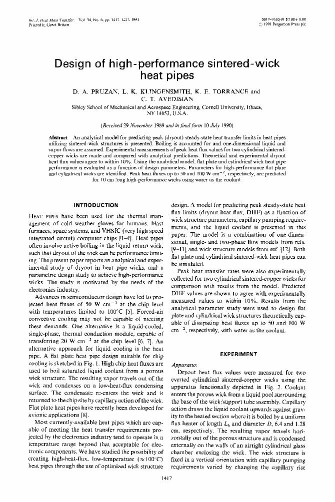
everted cylindrical sintered-copper wicks using the apparatus functionally depicted in Fig. 2. Coolant enters the porous wick from a liquid pool surrounding the base of the wick/support tube assembly. Capillary action draws the liquid coolant upwards against grav- ity to the heated section where it is boiled by a uniform flux heater of length L,, and diameter D, 6.4 and 1.28 cm, respectively. The resulting vapor travels hori- zontally out of the porous structure and is condensed externally on the walls of an airtight cylindrical glass chamber enclosing the wick. The wick structure is fixed in a vertical orientation with capillary pumping requirements varied by changing the capillary rise
1417

IJIX D. A. PKLIZAY (‘/ l/l.
NOMENCLATURE
/I 1, heated area of wick s local liquid saturation
.4 ii cross-sectional flow area within wick .Y,, irreducible liquid saturation II inside diameter of wick I’ superficial fluid velocity in the .\--direction
.(/ gravitational acceleration within the wick
il,, latent heat of vaporization li superticial vapor velocity in the r-direction ii - bulk permeability of wick within the wick
k,. A, relative pcrmcabilities for liquid and \-. i cylindrical coordinates (see Fig. 2).
vapor L distance from top of heater to liquid pool
(see Fig. 2)
L,, heated length of wick
I +11 maximum static hold-up height of wick
u, mass flow rate of vapor
PC maximum capillary pressure P,. P, local fluid pressures for liquid and
vapor
p, eKective vapor pressure
Greek symbols (5 wick thickness ;: porosity II tilt angle from horizontal AL,. 11, dynamic viscosities of liquid and
vapor
I’,. 0, densities of liquid and vapor Cr surface tension.
P \‘I, saturation pressure of fluid outside the wick Subscripts
(1’ applied heat flux per unit arca I liquid phase quantity
TC cffectivc capillary radius of curvature \ vapor phase quantity
height. L. between the liquid pool and the top of the heater. Dryout heat flux values wcrc measured as a function of capillary rise height using water at I atm pressure as the coolant. The apparatus and cxpcr- imental procedure arc identical to those described in
rcfs. [I2 141.
Two sintcred-copper wicks, labeled herein as wicks
#I and #3. were fabricated by Thermacorc Inc.
(Lancaster, Pennsylvania) using a sintering process suitable for producing high-performance heat pipe
wicks. Small copper particles were sieved through wire screens to achieve a desired particle size distribution. For wick # I, 150 mesh particles were used (range 130~170 mesh) ; for wick #3. 100 mesh (i.e. larger)
particles were used (and were screened to give a nar- rower particle size distribution). The particles wet-c poured into annular molds formed between inncl- thin-walled stainless steel tubes (35 cm in length and
I .28 cm in diameter) and equal length outer sleeves of cithcr 1.432 cm (wick # 1) or 1.916 cm (wick #2) diameter. Under heat and pressure the particles were partially fused and sintered together and bonded to
GRAVITY
SATURATED LIQUID
3at plate heat pipe suitable for electronic cooling applications. wth a tixed wck length. variable tilt angle. 0.
and
UNIFORM HEAT FLUX
Q”
ADIABATIC SECTION -
Design of high-performance sintered-wick heat pipes 1419
SUPPORT TUBE
‘-WICK
FIG. 2. Everted cylindrical heat pipe geometry for exper- imental and analytical work, utilizing a fixed tilt angle
(0 = 90”) and variable capillary rise height, L.
the central tube. The external sleeves were removed, leaving finished wick/tube assemblies.
Wick properties Internal characteristics of the porous wick struc-
tures, such as capillary radius of curvature of the pores, r,, porosity, E, and bulk permeability, k, must be known in order to specify the flow characteristics of the wicks. Capillary radius of curvature is primarily a function of the average particle size. Porosity is a function of the particle size distribution, with a tighter distribution tending towards higher porosities [15]. The bulk permeability can be related to E and r, with the Kozeny-Carman relation [15]
(1)
The procedures for obtaining r,, E, k and the dryout heat flux are described in the following sections. The physical properties of the two sintered wicks are sum- marized in Table 1. Further details are available in refs. [13, 141.
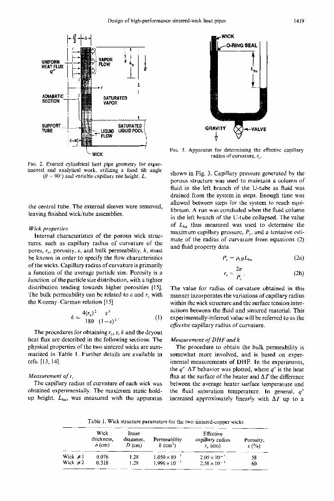
Measurement of r, The capillary radius of curvature of each wick was
obtained experimentally. The maximum static hold- up height, Lhu, was measured with the apparatus
FIG. 3. Apparatus for determining the effective capillary radius of curvature, r,.
shown in Fig. 3. Capillary pressure generated by the porous structure was used to maintain a column of fluid in the left branch of the U-tube as fluid was drained from the system in steps. Enough time was allowed between steps for the system to reach equi- librium. A run was concluded when the fluid column in the left branch of the U-tube collapsed. The value
of L” thus measured was used to determine the maximum capillary pressure, PC, and a tentative esti- mate of the radius of curvature from equations (2) and fluid property data
p, = PL9L” (24
The value for radius of curvature obtained in this manner incorporates the variations of capillary radius within the wick structure and the surface tension inter- actions between the fluid and sintered material. This experimentally-inferred value will be referred to as the efictive capillary radius of curvature.
Measurement of DHF and k The procedure to obtain the bulk permeability is
somewhat more involved, and is based on exper- imental measurements of DHF. In the experiments, the q”-AT behavior was plotted, where q” is the heat flux at the surface of the heater and AT the difference between the average heater surface temperature and the fluid saturation temperature. In general, q” increased approximately linearly with AT up to a
Table 1. Wick structure parameters for the two sintered-copper wicks
Wick Inner Effective thickness, diameter, Permeability capillary radius Porosity,
6 (cm) D (cm) k (cm’) rC (cm) E (%)
Wick #l 0.076 1.28 1.050 x lo-’ 2.05 x 10⁻³ 58 Wick #2 0.318 1.28 1.996x lo-’ 2.58 x IO-’ 60
break point. At the break point, larger increases m ,27 were observed with small increases in (/“. The breakpoint was identified as the dryout heat Rux for the wick. DHF \;alucs wcrc measured as a function of capillary rirc height L,, [13]. Related results for a screen mesh wick are reported in ref. [12]. Both studies ~~scd Mater. ethanol. and their mixtures as working
Ruids. A simple theory is available [Y] which relates the
bulk permeability to DHF at large values of the capil- lary rise height. In this limit, it is assumed that the prcssurc drop encountered by the fluid is due to grav- ity and viscous flow through the wick. The pressure
drop due to two-phase flow in the heated section is neglected. Under these conditions, the drynut heat
flux can bc equated to the product of the maximum liquid mass Row rate through the wick and the latent
heat of vaporization of the coolant. The maximum
liquid flow rate is round, in turn. by equating the peak
capillary pressure in the wick to the pressure drop
associated with single-phase liquid tlow through the
wick. Combining these relations, there results
DHF = k$
This expression relates DHF to I<, L,,,,, the heater
length, L,,. and the capillary rise height. L.
When fluid and wick properties arc constant, equa- tion (3) predicts a linear relationship bctwecn DHF
and I ;(L- 1,,!2). This linear behavior may be expected to describe experimental DHF data only
when the capillary rise height is large (i.e. L x I,,,) and the two-phase pressure drop is small. Under such
conditions, a linear best-fit line drawn through the measured large-l, DHF data and the previously mea-
sured L,, value (plotted on the abscissa) can be used with equation (3) to determine an effective L,,,, and
bulk permeability. The effective L,,,, is then used with equation (2) to find the effective capillary pressure.
Dryout heat flux data are plotted against l;‘(L-L,/2) in Fig. 4 for sintered wicks # 1 and # 2. Data could not be obtained at large enough L values to draw accurate straight ‘single-phase’ lines. Cubic polynomial curves were best fit to the measured DHF
and L,,,, data and ‘single-phase’ lines were drawn tan- gent to the cubic fit curves at DHF = 0. The ‘singlc-
phase’ lines were used with equations (2) and (3) to determine the effective capillary radius of curvature and the bulk permeability values listed in Table I. Note that for sintered wick # 1. Fig. 4(a), the resulting straight line provides a good fit to Ihe two lowest DHF points suggesting that these points arc in the
linear region described by equation (3).
Wick porosity was not measured directly but was inferred from the measurements of k and r, using the KoLcny Carmen relation, equation (I). The resulting values of?: are listed in Table 1. Note that the porosit! values arc in qualitative agreement with the scanning
electron microscope photographs shown in Fig. 5. Furlhermorc. the cff‘ective capillary radius of cur- \ature values. I’,, listed in Table 1 are also in qualt-
tativc accord with the photographs. The photographs in Fig. 5 were taken alIer the completion of the boiling experiments.
THEORY
Single- and two-phase analytical models have been
proposed for predicting dryout heat flux values in screen-wick and sintered-wick heat pipes [9-121. The
present two-phase model for sintered-wick heat pipes assumes that most system variables arc functions of the .v-coordinate only [I I] (see Fig. 2). For cylindrical gcometrics an exception is the cross flowing vapor velocity which, from continuity, must also vary with radius. Thermal equilibrium between liquid and vapor is assumed at the saturation temperature cor-
responding to the system operating pressure. Thertnal conduction across the wick is neglected and all energy transfer within the wick is assumed to result rrom phase change at the heated wall [ 10. 1 I]. Further. fluid tlow is governed by the Darcy momentum equations taking into account reduced pcrmcabilities when both phases arc present. Relative permcabilities for liquid and vapor are assumed to bc cubic functions of the local saturation, S [16]. Capillary pressure, P,. is assumed to be constant [I 1, 121. as are all fluid and wick properties. The resulting governing equations are written in a lhrm suitable for both cylindrical and flat plate (D = infinity) gcometrics. Heat pipes with fixed rise height. L.. and variable tilt angle, il. Fig. I.
or fixed tilt angle and variable rise height. Fig. 2. can be simulated. The latter geometry is similar to that used in the experiment and is employed in the fol-
lowing analysis.
Flow in the adiabatic section is governed by the sin&-phase Darcy momentum equation, given by
where L: is the liquid-phase Darcy superficial velocity in the s-direction.
In the heated section, the vapor production rate IS governed by the applied heat flux through the energy equation (neglecting conduction)

Design of high-performance sintered-wick heat pipes 1421
sinlerad wick #l Slntered wick #2
1.4 N^ E y 1.0 5
$ 0.6 D
-0.6
(*) w”
(a) 04
-10’ ’ ’ ’ ’ ’ ’ ’ ’ c ’ ’ ’ 0 0.01 0.02 0.04 0.05 0.06
(*) m-‘)
FIG 4. Cubic fit curves of the experimental DHF data and ‘single-phase’ straight lines : (a) wick # 1 ; (b) wick #2.
where &fV is the mass flow rate of vapor in the r-
direction. From equation (5) and the principle of vapor conservation, the superficial vapor velocity in
the r-direction, V, can be found as a Function of Y. The liquid continuity and the two-phase Darcy momen- tum equations in the heated section are
o=_::+p,6 ;+I g [ 1 (6)
h
$J-p,gsinQ 1 (74
V= _~!g! (7b)
where the liquid and vapor pressures are denoted by P, and P,. With V found from equation (5) and vapor continuity, an effective vapor pressure, P,,, can be obtained by integrating equation (7b) across the wick thickness 6
P, = P,,, + n;l,P”
2rn% PA, (8)
Additional relations are needed to complete the problem specification. The liquid and vapor relative permeabilities, k, and k,, are assumed to be cubic functions of the local liquid saturation, S
k, =S3 (94
k, = (1 -S)‘. (9b)
The difference between P., and P, is the capillary press- ure PC, which, from equation (2) can be related to rr
and u by
(10)
The effective pressure given by equation (8) is used to
evaluate P,. The capillary pressure PC is assumed to be constant throughout the wick. The capillary radius of curvature usually varies within a wick structure,
but a single effective value is used in the present model.
The cubic relative permeability/constant capillary pressure formulation of equations (9) and (10) was
used previously for simulating the peak heat flux in a screen-wick heat pipe [12]. This particular com- bination was selected after comparing analytical pre- dictions from seven different relative permeability/
capillary pressure models against experimental data (see refs. [ 12, 141 for details). Only accepted models
from the porous media literature were considered. Application of the cubic permeability/constant capillary pressure formulation to the sintered-wick heat pipes of the present study appears to be justified by the agreement between experiment and theory.
Solution method Five unknowns appear in equations (4)-(10) ;
namely, U, V, P,, P, and S. All variables in the heated

FIG. 5. Scanning electron microscope pictures at 200 x magnification. The white bars at the lower right represent 100 pm (0.01 cm) : (a) wick # I : (b) wick #?.
section depend on s. and V depends on Y as well. The
equations were solved as a function of the applied heat flux, q”, using known wick geometry. wick/fluid properties, and capillary rise height. The liquid vcl-
ocity U through the adiabatic section was determined from global heat and mass balances on the heated section, since the inflow of liquid to the heated section must just balance the production of vapor in that section. Liquid pressure at the base of the heated section was found by integrating equation (4). Equa- tions (6))( 10) are strongly nonlinear and were solved by finite difference techniques. The solution was marched upwards from the base of the heated section using liquid velocity and pressure at the base of the heated section as boundary conditions. An adjustable step size was used to ensure accurate evaluation of pressure and saturation gradients. The dryout heat flux was assumed to be reached when the local steady- state saturation at the top of the heated section reached an irreducible liquid saturation level, S,,,.
Actual S,,, vlalues for the two experimental wicks wcrc not available, but as shown in Table 7. DHF is I&- tively insensitive to S,,,. A value of 1% was therefore assumed.
Rrsults
Representative normalized velocity, pressure and saturation distributions for the liquid in the heated section at dryout conditions arc shown in Fig. 6.
Table 2. Influence of S,,, on predicted DHF for wick # 3
C‘apillary rise DHF (W cm ‘) with S,,T set to height, 1, (cm) I .OO% 10.0% 20.0x,
Design of high-performance sintered-wick heat pipes 1423
**.. 1 *... ’
0 ’ . ’ . ’ . ’ . ’ . ’ 0 1 2 3 4 5 6
Di6iance horn base of heater (cm)
FIG. 6. Normalized liquid-phase velocity, pressure and satu- ration profiles in the heated section at DHF conditions for
wick # 2 with L = 10 cm.
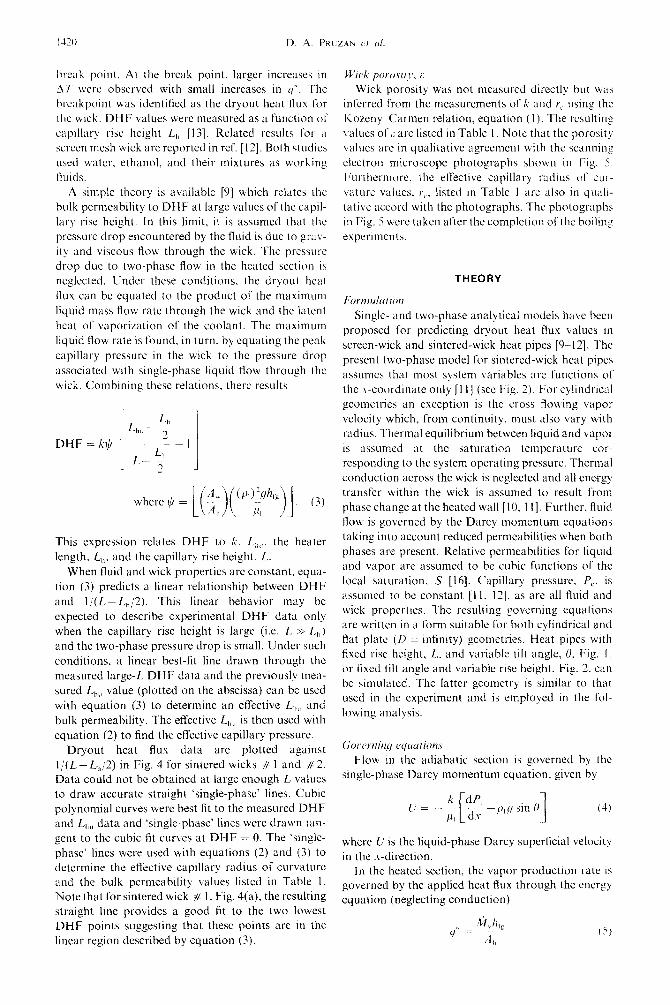
Results pertain to wick # 2 with L = 10 cm. The linear decrease in superficial liquid velocity across the heated section follows from the uniform heat flux condition and the neglect of heat conduction in the wick. The vapor velocity is also constant along the entire heated length. The step decrease in liquid saturation at the base of the heater arises in order to generate sufficient local vapor relative permeabilities commensurate with the vapor velocity and the local effective vapor press- ure.
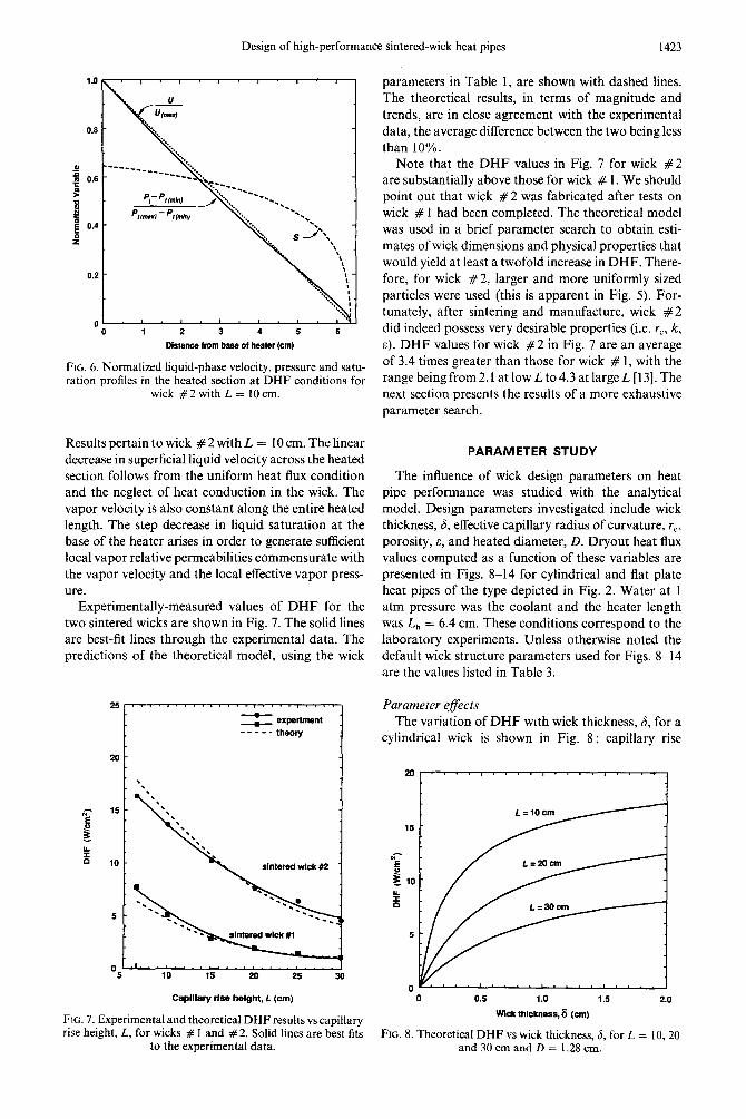
Experimentally-measured values of DHF for the two sintered wicks are shown in Fig. 7. The solid lines are best-fit lines through the experimental data. The predictions of the theoretical model, using the wick
25
i
=t: experiment -----theory
.I.. *, . . *. . (
10 15 20 25
Capillary rt66 height, L (cm)
FIG. 7. Experimental and theoretical DHF results vs capillary rise height, L, for wicks # 1 and #2. Solid lines are best fits
to the experimental data.
parameters in Table 1, are shown with dashed lines. The theoretical results, in terms of magnitude and trends, are in close agreement with the experimental data, the average difference between the two being less than 10%.
Note that the DHF values in Fig. 7 for wick #2 are substantially above those for wick # 1. We should point out that wick #2 was fabricated after tests on wick # 1 had been completed. The theoretical model was used in a brief parameter search to obtain esti- mates of wick dimensions and physical properties that would yield at least a twofold increase in DHF. There- fore, for wick #2, larger and more uniformly sized particles were used (this is apparent in Fig. 5). For- tunately, after sintering and manufacture, wick #2 did indeed possess very desirable properties (i.e. rC, k, a). DHF values for wick #2 in Fig. 7 are an average of 3.4 times greater than those for wick # 1, with the range being from 2.1 at low L to 4.3 at large L [13]. The next section presents the results of a more exhaustive parameter search.
PARAMETER STUDY
The influence of wick design parameters on heat pipe performance was studied with the analytical model. Design parameters investigated include wick thickness, 6, effective capillary radius of curvature, r,, porosity, a, and heated diameter, D. Dryout heat flux values computed as a function of these variables are presented in Figs. 8-14 for cylindrical and flat plate heat pipes of the type depicted in Fig. 2. Water at 1 atm pressure was the coolant and the heater length was L,, = 6.4 cm. These conditions correspond to the laboratory experiments. Unless otherwise noted the default wick structure parameters used for Figs. 8-14 are the values listed in Table 3.
Parameter effects The variation of DHF with wick thickness, 6, for a
cylindrical wick is shown in Fig. 8: capillary rise
20’ 1 -4
16
5
0 0 0.5 1.0 1.5 2.0
Wick thickness, 6 (cm)
FIG. 8. Theoretical DHF vs wick thickness, 6, for L = IO,20 and 30 cm and D = 1.28 cm.

D. A. PRUZAN et (I/
0 0 0.002 0.004 0.006 0.006 0.010
Capillary radius of curvature, rc (cm)
FIG. 9. Theoretical DHF vs effective capillary radius 01 curvature, Y,, for L = IO, 20 and 30 cm and II) = I .2X cm.
height. I!,. is the curve parameter. For the given cyl- indrical dimensions, DHF increases monotonically with increasing wick thickness. The greatest improve- ments occur at small wick thicknesses with marginal
improvements for 6 greater than about 2.0 cm. The observed monotonic increase in DHF with i? is a func- tion of flow path geometries for both the liquid and vapor. A thicker wick structure permits a lower liquid velocity in the wick for a given applied heat flux. The associated lower viscous pressure drop can lead to a higher peak heat flux. In the heated section, a thicker
wick tends to decrease the peak heat flux by increasing the vapor pressure drop along the lengthened flow path. With cylindrical geometries this latter effect is attenuated by the radial decrease in superficial vapor
velocity as the flow area increases with
radius. Dryout heat flux is plotted against Y,
indrical wick using L as the parameter
increasing
for a cyl- in Fig. 9.
‘9
0 ~~~‘~‘~““‘N’ 0.50 0.52 0.54 0.56 0.56 0.60
Porosity, E
FIG. 10. Theoretical DHF vs porosity, C. for three elt‘ecttve capillary radii of curvature. D = I .28 cm. L = 30 cm.
2
0 0 0.5 1.0 1.5 2.0
Wick thickness,& (cm)
FIG. I I. Theoretical DHF vs wick thickness, (5. for three cylindrical wicks and a hat plate wick (II = inhnity). all at 1, = 30 cm. The optimum thickness for the flat plate wick is
roughly 1.41 cm.
An optimum effective capillary radius of cutvature appears for each of the three capillary rise heights
shown. Optimum values occur due to the influence of rL, on both bulk permeability and capillary pressure. A large effective radius of curvature results in an increased bulk permeability through equation (I) (for a given porosity, c). This increased permeability decreases flow resistance in the wick, thus increasing
peak heat flux capabilities. Conversely a large effective radius of curvature generates low capillary pressure (for a given coolant) through equation (2b). A lower capillary pressure decreases the wick’s ability to pump liquid up to the heated section, thus decreasing peak heat flux. The internal balance between these two effects leads to the observed maxima in DHF. Clearly. in a design choice, the effective capillary radius of
curvature must be selected to allow for both the capil-.
15
i
--D=C-
__-- ___---
__-- _.rr
,’ -----I /’
“E _ ,’
go - 8’ ,l’ L=lOcm
E _ 1
L=zOcm 4
L=3Ocm 1
0 0.5 1.0 1.5 2.0
Wick thickness.8 (Cm)
FIG. 12. Theoretical DHF vs wick thickness, b, for a hat plate wick at L = IO, 20 and 30 cm. Dashed line is for a
cylindrical wick at L = IO cm from Fig. 8.

Design of high-performance sintered-wick heat pipes 1425
5
t
Capillary rise height& (cm)
FIG. 13. DHF vs capillary rise height, L, for the high- performance wick structures and experimental wicks # 1 and # 2 with @ = 90”. Experimental results are from Fig. 7.
Iary rise height and heat dissipation needed in an application.
Dryout heat flux is plotted against porosity, E, for three effective capillary radii of curvature in Fig. 10. A cylindrical wick with L = 30 cm is assumed. The three r, values vary between the optimal and maximal values for L = 30 cm in Fig. 9. The peak heat flux increases rapidly with increasing porosity for r, =2x IO-’ and 3x 10m3 cm. A more gradual increase is seen for r, = 4 x 10m3 cm. Small increases in porosity can lead to large improvements in bulk permeability through equation (l), when other par- ameters are held fixed. As mentioned previously, an increased ~~eabil~ty leads to a lower fIow resistance in the wick and thus to higher peak heat fluxes. Porosity of a sintered wick is a function of the sinter- ing process and the particle size distribution. A narrow particle size distribution can lead to increased wick porosity [15].
The effect of heated diameter, D, on performance is shown in Fig. 11 with DHF plotted against wick thickness, 6, for three cylindrical wicks and a flat plate wick, all at L = 30 cm. Dryout heat flux values are seen to decrease with increasing heated diameter at a
"0 15 30 45 60 73 w
6 wwm
FIG. 14. Theoretical DHF vs tilt angle, 0, for the high- performance wick structures with wick lengths of 10 and 30 cm using effective capillary radii of curvature of 8.35 x IO-’
and 3.58 x 1O-e3 cm, respectively.
given S. In the range of moderate wick thickness, 6 < 0.75 cm, heat pipe performance appears to be a weak function of heated diameter for the three cyl- indrical wicks. The influence of flat plate vs cylindrical geometry on heat pipe performance with respect to wick thickness is also shown in Fig. 11. As shown previously in Fig. 8, cylindrical wick structures exhibit a monotonic increase in DHF with increasing 6 over the range shown. For the Fiat plate wick a peak DHF is observed at roughly 6 = 1.41 cm, beyond which the peak heat flux decreases. The difference in behavior of DHF with wick thickness for the two geometries can be explained in terms of liquid and vapor flow paths. For both cylindrical and flat plate geometries the resistance to liquid flow decreases as the wick thickness is increased. In flat plate wicks the increased resistance to vapor flow through the thicker porous layer is not offset by an increasing flow area as it is in cylindrical geometries. The balance between the decreased liquid resistance and the increased vapor resistance leads to an optimum wick thickness occur- ring for the flat plate wick. The resulting optimum value for 6 is a function of the capillary rise height, L,
Table 3. Wick structure parameters for parameter study
Wick thickness,
6 (cm)
Heated diameter, I) (cm)
Permeability, k (cm’)
Effective capillary radius,
rC (em) Porosity,
E (%)
Default 0.318 1.28/infinity 1.430 x lo-’ 2.58 x 1o-3 ST High-performance cylindrical wick 2.000 1.28 4.250 x lo-’ 3.58 x 10-j 61 High-performance flat plate wick 0.500 infinity 4.250 x IO-’ 3.58 x lo-” 61
--
as shown in Fig. 12. The dashed curve is from Fig. 8 predicted for the IO cm flat plate and cylindrical weeks for a cylindrical wick with I_ = IO cm. using water as the coolant.
The influence of eflective capillary radius of cur- vature. i L, and porosity. E. on DHF appears to bc nearly independent of geometry. Trends for flat plate wicks are not reported here but are similar to those shown in Figs. 9 and IO for cylindrical geometries.
CONCLUSIONS
The foregoing results were used to design high- performance flat plate and cylindrical wick structures.
The flat plate wick thickness was chosen to be 0.5 cm to allow a range of operation of 0 d L < 30 cm. A wick thickness of 2.0 cm was chosen for the cylindrical wick as beyond this point only marginal improvc-
ments in DHF were predicted. Heater lengths of 6.4 cm were selected, and a heated diameter of 1.28 cm for the cylindrical wick, as these values are identical to those used in the experiments. An etfective capillary
radius of curvature of 3.58 x IO ’ cm was chosen for both wicks to allow operation to a capillary rise height of 35 cm. It was assumed that porosity could be increased to 60% for both wicks, a slight improvement over that of experimental wick #2. The sclectcd design parameters for the two high-performance wick structures are listed in Table 3. It should be noted that
the high-performance design parameters were chosen based upon information presented in Figs. 8-12. These designs do not, however. represent the results
of a full optimization study.
A one-dimensional, two-phase model for predicting dryout heat fluxes in sintered-wick heat pipes has been
constructed. Predicted dryout heat flux values agree with experimental results for two sintered-copper wicks to within 10%. The influence of wick thickness. ij, effective capillary radius of curvature, I’,. porosity.
2:. and heated diameter, II, on heat pipe performance was studied parametrically. The parameter study was used to design high-performance flat plate and cyl- indrical wick structures. High-performance flat plate
and cylindrical wicks, 10 cm in length, arc shown to bc theoretically capable of dissipating 50 and 100 W cm -‘. respectively. using water as the coolant.
AcknoM,k~~lyrrnrnI.~----The authors would like to thank the following individuals : Mr Algerd Basilius of Hughes Aircraft and Dr Roop Mahajan of AT&T for technical counsel ; Kim Ann Shollenberger for generating the numerical results ; Mr N. Gcmert of Thermacore, Inc.. for invaluable advice and assistance on wick fabrication; and Mr J. Hunt for the photographs in Fig. 5. Support for this work came from the Semiconductor Research Corporation under Projects Nos. X6-01-070-02 and 87-MP-070-02 and the National Science Foundation through grant No. CBT-8451075.
REFERENCES
Predicted DHF values for the two high-per- formance structures are plotted against capillary rise height, L, in Fig 13. Also shown arc the experimental data from Fig. 7 for wicks # 1 and # 2. The optimized cylindrical wick is theoretically capable of peak heat
transfer rates roughly 2.3 times those experimentally measured for sintered wick # 2. Further, the rates are almost twice those for the high-performance fiat plate
wick.
1
2
Dryout heat flux predictions are plotted as a func- tion of tilt angle, 0, in Fig. 14 for the two optimized structures. A rise height, L, of 30 cm is assumed for
the lower curves. Clearly, the predicted DHF values increase strongly as the tilt angle 0 is decreased. Thus the experimental and theoretical results shown in Fig. 13 for 0 = 90 can be expected to increase dra-
matically as the tilt angle is reduced.
6
I
The influence of maximum capillary rise height is also shown in Fig. 14. Results are shown for wick structures with maximum rise heights of L = 10 cm. The 10 cm wicks are identical to the 30 cm high- performance wick structures detailed in Table 3 but with the effective capillary radius of curvature increased to 8.35 x IO- ’ cm. The maximum static
hold-up height, L,,, is then reduced to I5 cm. The IO cm flat plate and cylindrical structures are theor- etically capable of DHF values roughly 3.3 and 2.5 times those of the 30 cm wicks. Peak heat fluxes of the order of 50 and 100 W cm ‘. respectively, arc
A. Faghri, D. B. Reynolds and P. Faghri, Heat pipes for hands, Mrch. Engng ill(6). 70-74 (1989). V. 1. Tolubinskiy and Y. E. N. Shevchuk, High-tem- perature heat pipes (survey). Heat Tran$rr-SW Rcs. 20( 1). 79-87 (1988). P. D. Dunn and D. A. Reay, Heur Pipes, 3rd Edn. Pergamon Press, Oxford (1982). L. Waller, An old idea may solve VHSIC coohng problem, Electronics 19-20 (5 August 19X5). A. E. Bergles, High flux boiling applied to micro- electronics thermal control, Inl. Commun. Hear Mus., Trumfer 15,509~531 (1988). A. J. Blodgett, Jr., Microelectronics packaging, .%ietr/. Am. 249, 86.-96 (1983). S. Oktay, R. Hannemdnn and A. Bar-Cohen, High heat from a small package, Mech. Engng 108, 36-42 (1986). A. Basilius, H. Tanzer and S. McCabe. Thermal man- agement of high power PWBs through the USC of heat pipe substrates, Proc. Sixlk Annuul Int. Electron. Prrck- aging C’orzf:, San Diego, California (1986). K. R. Chun. Some experiments on screen wick dry-out limits. J. Heur Trunsfer 94, 4665 1 ( 1972). F. Ruel, Heat transfer limitations of porous sintcred wicks with arteries. ASME Proc. IVXH Natn. Heat Trcrrr.+ f&r (‘cm/., HTD-96 Vol. 1. pp. 507 515. ASME. New York (1988). B. S. Singh and R. M. Shaubach, Boiling and two-phase flow in the capillary porous structure of a heat pipe. In Multiphast, Transport in Porous Mda (Edited by R. Eaton. K. S. Udell and M. Kaviany). HTD-Vol. Y I. pp. 61 6X. ASME, New York (1987). D. A. Pruzan, K. E. Torrance and C. T. Avedisian, Two- phase flow and dryout in a screen wick saturated with a fluid mixture, Int. .I. Heat Muss Tran.$tr 33, 673 681 (1990).
Design of high-performance sintered-wick heat pipes 1421
13. L. K. Klingensmith, Dryout heat-flux performance of versity, Sibley School of Mechanical and Aerospace sintered copper wicks, Report E-88-08, Sibley School of Engineering, Ithaca, New York (1989).
Mechanical and Aerospace Engineering, Cornell Uni- 15. J. Bear, Dynamics of Fluids in Porous Media, pp. 41, versity, Ithaca, New York (1988). 166. American Elsevier, New York (1972).
14. D. A. Pruzan, Experimental and analytical inves- 16. M. R. J. Wyllie, Relative permeability. In Petroleum tigations into enhanced peak boiling heat transfer from Production Handbook (Edited by T. C. Frick), Vol. 2, capillary fed porous media, Ph.D. Thesis, Cornell Uni- Chap. 25. McGraw-Hill, New York (1962).
CONCEPTION DE CALODUCS PERFORMANTS A MECHE FRITTEE
R&urn-n presente un modele analytique pour predire les limites thermiques de pointe permanente (assechement) dans des caloducs utilisant des structures de m&he frittee. L’ebullition est prise en compte et on suppose des Ccoulements monodimensionnels de liquide et de vapeur. Des mesures experimentales de flux thermique sont faites pour deux mtches cylindriques de cuivre fritte et elles sont comparees aux predictions analytiques. Les valeurs thtoriques et experimentales d’assechement s’accordent a mieux que 10%. En utilisant le modtle analytique, on &value en fonction des paramttres operatoires les performances de caloducs a m&he aplatie ou cylindrique. On identifie des paramttres pour les mkhes a haute perform- ance. Des pits a flux thermiques allant respectivement jusqu’a 50 et 100 W cm-* sont predits pour des
meches de 10 cm de longueur avec l’eau comme fluide.
KONSTRUKTION HOCHEFFIZIENTER WARMEROHRE MIT EINEM SINTERDOCHT
Zusammenfassung-Es wird ein analytisches Model1 zur Berechnung der “dryout”-Grenze bei stationarer Warmeiibertragung in Warmerohren mit Sinterdocht-Strukturen vorgestellt. In dem Model1 werden viele Vorginge beriicksichtigt, und es wird eindimensionale Fhlssigkeits- und Dampfstromung angenommen. Fur zwei unterschiedliche zylindrische gesinterte Kupferdochte wird die maximale Warmestromdichte experimentell bestimmt und mit den Berechnungen verglichen. Dabei ergibt sich eine Ubereinstimmung innerhalb 10%. Das analytische Model1 wird zur Ermittlung des Einflusses der Konstruktionsparameter auf das Verhalten eines Warmerohres mit ebenem und zylindrischem Docht werwendet. Hierfiir werden die HaupteinfluBgroBen ermittelt. Fur 10 cm lange hocheffiziente Dochte werden mit Wasser als Kiihlmittel
Spitzenwerte der Warmestromdichte von 50 bzw. 100 W cm-* berechnet.
PAC=IET 3@@EKTWBHbIX TEI-LJIOBbIX TPYE CO CI-IErIEHHbIM @MTHJIEM
AoloTnun+-Onecbmaercn aria.imrmrecKa~ Monenb n.nr pacqera npenenon MaKcrihm_nbuoro (K~HTHWCKOI-0) crarr$soHapHoro TennonepeHOCa B Tennonbrx rpy6ax c riCnoJIb3onamieM crpyrcryp co cne¶eHHbIM r$urHneM. YmfrbmaeTcn rofneHae u npelulonaraercr. 9ro re¶errsm *mocrsr H napa KBnPIOTCff OAHOMepHbIMH. ~pOBOAKTC~ 3KCIlC.pHMeHTUIbHbIe H3MepCHHK MaKCHMUIbHbIX 3HSleHHti Ten-
nonoro nOTOKa Ann AByX UEJIHHApHWCKHX Cne~eHHOMeAHbIX @,,TKneir, A ,,O,I,'W%IHbE ,JaHHbIe COIIOC-
TaBnSH)TCII C aHaJIElTWIeCKHht&i pe3yJIbTaTaMil. TeopeTawcK~e H SKClIepHMeHTWIbHbIe 3HaYeHBR
KpIiTHWCICOrO TelLlIOBOrO IIOTOKa COBIIa&+WT C Tom0crbm A0 10%. Ha 0CHOBe aHaJlSTHllWK0i-i
MOAenU OYeHHBaIOTCR pa6owe XapaKTepACTHKH TeIInOBbIX rpy6 C IIJIOCKEM H I~WIIHA~)D~CCKHM
@iTHJIIIMR B 3aBHCAMOCTH OT KOHCTpJ’KTHBHbtX IlapaMe’QWB. OlIp,ZAenKIoTCK lIapaMCTp&J 3@eKTHBHblX
nnocKor0 ri mrmimrpsi~ecxoro @arsineii. &n ~@*KTHBH~IX t$H-rweii ansi~0i-i 10 CM, ricnonbsyrouujx B Kaqecrne xnanaretira BOAy, paCCSHTaHbI MaKcmmnbHMe TerrnonbIe nOTOK~,c0CTannx10~e ~~OTB~TCT-
BeHHo AO 50 a 100 BT CM-~.