design of earth-quake resistant multi-storied rcc building
TRANSCRIPT
1 | P a g e
DESIGN OF EARTH-QUAKE RESISTANT
MULTI-STORIED RCC BUILDING ON A
SLOPING GROUND
A THESIS SUBMITTED IN PARTIAL FULFILLMENT OF THE REQUIREMENTS FOR THE DEGREE OF
BACHELOR OF TECHNOLOGY
IN
CIVIL ENGINEERING
BY
SAPTADIP SARKAR
Under the Guidance of
Dr. K.C.Biswal
Department of Civil Engineering
National Institute of Technology
Rourkela
2010

2 | P a g e
CANDIDATES DECLARATION
I hereby declare that the work which is being presented in this project titled “DESIGN OF
EARTH-QUAKE RESISTANT MULTI-STORIED RCC BUILDING ON A SLOPING GROUND” for
partial fulfilment of the requirements for the award of degree of BACHELOR OF
TECHNOLOGY in CIVIL ENGINEERING submitted in the NATIONAL INSTITUTE OF
TECHNOLOGY,ROURKELA is an authentication record of my work carried during the period
from may 2009 under the supervision of DR.K.C.Biswal
Date:
Place: SAPTADIP SARKAR Department of Civil Engg.
National Institute of Technology, Rourkela

3 | P a g e
NATIONAL INSTITUTE OF TECHNOLOGY ROURKELA
CERTIFICATE
This is to certify that the thesis entitled, Design of DESIGN OF EARTH-QUAKE RESISTANT
MULTI-STORIED BUILDING ON A SLOPING GROUND submitted by MR.SAPTADIP SARKAR in
partial fulfilment of the requirements for the award of Bachelor of technology in Civil
Engineering at the National Institute of Technology, Rourkela is an authentic work carried
out by him under my supervision and guidance.
To the best of my knowledge, the matter embodied in the thesis has not been submitted to
any other University/Institute for the award of any degree.
Dr. K.C. Biswal Department of Civil Engg.
National Institute of Technology Rourkela-769008

4 | P a g e
ACKNOWLEDGEMENT
I would like to express my sincere gratitude to Dr. K.C .Biswal for his invaluable guidance. His
continuous encouragement and support has always been an inspiration and a source of
energy for me. I thank him for all of his valuable time, effort and help. I am also thankful to
Dr.S.K.Das and Dr.S.Pradyumna who helped me a lot with the software applications, without
which the project could not have been completed. Also my sincere thanks to all other
people who were directly or indirectly associated with the same in any other way.
5 | P a g e
LIST OF TABLES
Table No: Page No.
1) ANALYSIS RESULTS FOR 2 BAY SYSTEMS ON PLANE
AND ON A SLOPING GROUND FOR TWO STORY FRAME 24
2) ANALYSIS RESULTS FOR 4 BAY SYSTEMS ON PLANE
AND ON A SLOPING GROUND FOR TWO STORY FRAME 27
3) ANALYSIS RESULTS FOR 2 BAY SYSTEMS ON SLOPING
AND ON A SLOPING GROUND FOR FOUR STORY FRAME 31
4) ANALYSIS RESULTS FOR 4 BAY SYSTEMS ON SLOPING
AND ON A SLOPING GROUND FOR FOUR STORY FRAME 35
5) ANALYSIS RESULTS FOR 2 BAY SYSTEMS ON SLOPING
AND ON A SLOPING GROUND FOR SIX STORY FRAME 42
6) ANALYSIS RESULTS FOR 4 BAY SYSTEMS ON SLOPING
AND ON A SLOPING GROUND FOR SIX STORY FRAME 49
6 | P a g e
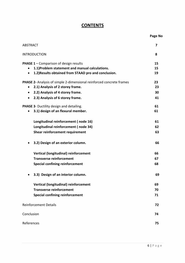
CONTENTS Page No ABSTRACT 7 INTRODUCTION 8 PHASE 1 – Comparison of design results 15
1.1)Problem statement and manual calculations. 15
1.2)Results obtained from STAAD pro and conclusion. 19
PHASE 2- Analysis of simple 2-dimensional reinforced concrete frames 23
2.1) Analysis of 2 storey frame. 23
2.2) Analysis of 4 storey frame. 30
2.3) Analysis of 6 storey frame. 41
PHASE 3- Ductility design and detailing. 61
3.1) design of an flexural member. 61
Longitudinal reinforcement ( node 16) 61
Longitudinal reinforcement ( node 34) 62
Shear reinforcement requirement 63
3.2) Design of an exterior column. 66
Vertical (longitudinal) reinforcement 66
Transverse reinforcement 67
Special confining reinforcement 68
3.3) Design of an interior column. 69
Vertical (longitudinal) reinforcement 69
Transverse reinforcement 70
Special confining reinforcement 71
Reinforcement Details 72 Conclusion 74 References 75
7 | P a g e
Abstract
This project named as “DESIGN OF EARTH-QUAKE RESISTANT MULTI-STORIED RCC
BUILDING ON A SLOPING GROUND” involves the analysis of simple 2-D frames of varying
floor heights and varying no of bays using a very popular software tool STAAD Pro. Using the
analysis results various graphs were drawn between the maximum axial force, maximum
shear force, maximum bending moment, maximum tensile force and maximum compressive
stress being developed for the frames on plane ground and sloping ground. The graphs used
to drawn comparison between the two cases and the detailed study of “SHORT COLOUMN
EFFECT” failure was carried up. In addition to that the detailed study of seismology was
undertaken and the feasibility of the software tool to be used was also checked. Till date
many such projects have been undertaken on this very topic but the analysis were generally
done for the static loads i.e. dead load, live load etc, but to this the earthquake analysis or
seismic analysis is to be incorporated. To create a technical knowhow, two similar categories
of structures were analyzed, first on plane ground and another on a sloping ground. Then
the results were compared. At last the a structure would be analyzed and designed on
sloping ground for all possible load combinations pertaining to IS 456, IS 1893 and IS 13920
manually.

8 | P a g e
INTRODUCTION
Seismology is the study of vibrations of earth mainly caused by earthquakes. The study of
these vibrations by various techniques, understanding the nature and various physical
processes that generate them from the major part of the seismology. [2]*
Elastic rebound theory is one such theory, which was able to describe the phenomenon of
earthquake occurring along the fault lines. Seismology as such is still a very unknown field of
study where a lot of things are yet to be discovered. [2]*
The above Picture is showing the fault lines and we can see that epicentres are all
concentrated all along the fault lines. The reason for seismic activities occurring at places
other than the fault lines are still a big question mark. Also the forecasting of earthquake
has not been done yet and would be a landmark if done so.
There is general saying that it’s not the earthquake which kills people but its the bad
engineering which kills people. With industrialization came the demand of high rise building
and came dangers with that.
9 | P a g e
.
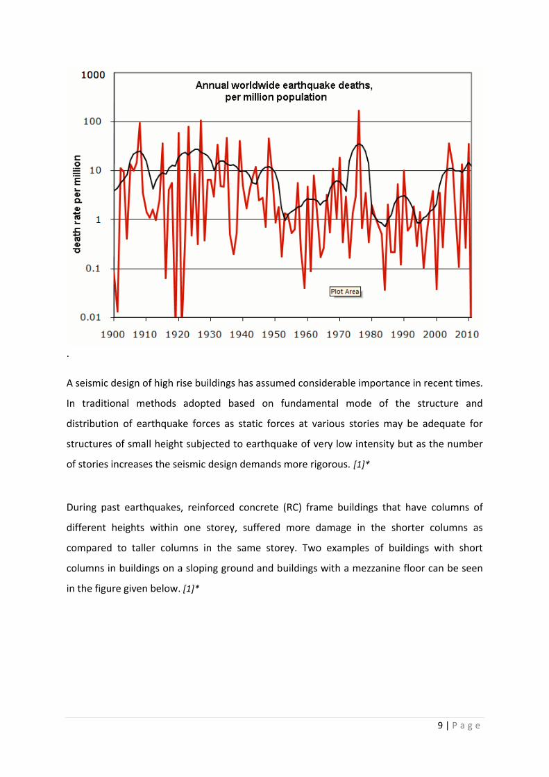
A seismic design of high rise buildings has assumed considerable importance in recent times.
In traditional methods adopted based on fundamental mode of the structure and
distribution of earthquake forces as static forces at various stories may be adequate for
structures of small height subjected to earthquake of very low intensity but as the number
of stories increases the seismic design demands more rigorous. [1]*
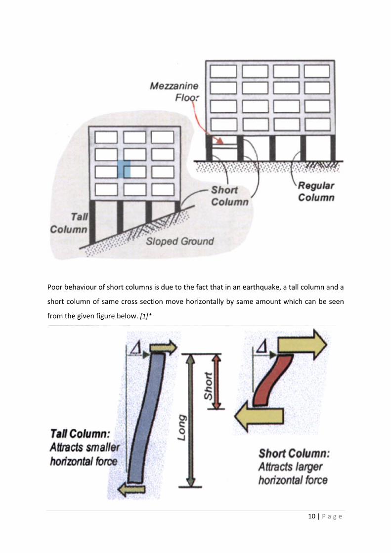
During past earthquakes, reinforced concrete (RC) frame buildings that have columns of
different heights within one storey, suffered more damage in the shorter columns as
compared to taller columns in the same storey. Two examples of buildings with short
columns in buildings on a sloping ground and buildings with a mezzanine floor can be seen
in the figure given below. [1]*
10 | P a g e
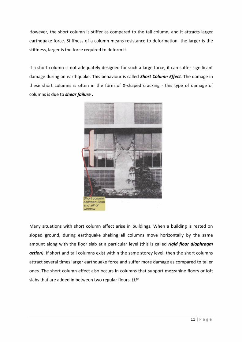
Poor behaviour of short columns is due to the fact that in an earthquake, a tall column and a
short column of same cross section move horizontally by same amount which can be seen
from the given figure below. [1]*
11 | P a g e
However, the short column is stiffer as compared to the tall column, and it attracts larger
earthquake force. Stiffness of a column means resistance to deformation- the larger is the
stiffness, larger is the force required to deform it.
If a short column is not adequately designed for such a large force, it can suffer significant
damage during an earthquake. This behaviour is called Short Column Effect. The damage in
these short columns is often in the form of X-shaped cracking - this type of damage of
columns is due to shear failure .
Many situations with short column effect arise in buildings. When a building is rested on
sloped ground, during earthquake shaking all columns move horizontally by the same
amount along with the floor slab at a particular level (this is called rigid floor diaphragm
action). If short and tall columns exist within the same storey level, then the short columns
attract several times larger earthquake force and suffer more damage as compared to taller
ones. The short column effect also occurs in columns that support mezzanine floors or loft
slabs that are added in between two regular floors. [1]*
12 | P a g e
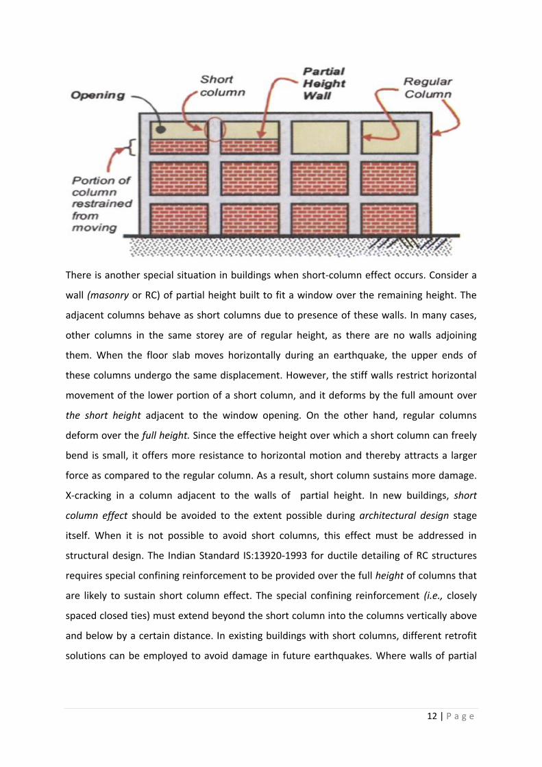
There is another special situation in buildings when short-column effect occurs. Consider a
wall (masonry or RC) of partial height built to fit a window over the remaining height. The
adjacent columns behave as short columns due to presence of these walls. In many cases,
other columns in the same storey are of regular height, as there are no walls adjoining
them. When the floor slab moves horizontally during an earthquake, the upper ends of
these columns undergo the same displacement. However, the stiff walls restrict horizontal
movement of the lower portion of a short column, and it deforms by the full amount over
the short height adjacent to the window opening. On the other hand, regular columns
deform over the full height. Since the effective height over which a short column can freely
bend is small, it offers more resistance to horizontal motion and thereby attracts a larger
force as compared to the regular column. As a result, short column sustains more damage.
X-cracking in a column adjacent to the walls of partial height. In new buildings, short
column effect should be avoided to the extent possible during architectural design stage
itself. When it is not possible to avoid short columns, this effect must be addressed in
structural design. The Indian Standard IS:13920-1993 for ductile detailing of RC structures
requires special confining reinforcement to be provided over the full height of columns that
are likely to sustain short column effect. The special confining reinforcement (i.e., closely
spaced closed ties) must extend beyond the short column into the columns vertically above
and below by a certain distance. In existing buildings with short columns, different retrofit
solutions can be employed to avoid damage in future earthquakes. Where walls of partial

13 | P a g e
height are present, the simplest solution is to close the openings by building a wall of full
height - this will eliminate the short column effect. [1]*

14 | P a g e
PHASES OF THE PROJECT
The project was divided into different phases. They are as follows:-
Phase-1- Comparison of design results of STAAD Pro and same problems done manually.
Phase-2- Analysis of simple 2-dimensional reinforced concrete frames and as such both
static loads(dead, live and load combinations) and dynamic load (Earth quake load) are to
be considered frames first on a plain ground and then on a sloping ground.
Phase-3- Ductility design and detailing.
15 | P a g e
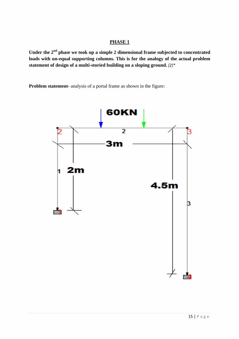
PHASE 1
Under the 2nd
phase we took up a simple 2 dimensional frame subjected to concentrated
loads with un-equal supporting columns. This is for the analogy of the actual problem
statement of design of a multi-storied building on a sloping ground. [2]*
Problem statement- analysis of a portal frame as shown in the figure:
16 | P a g e
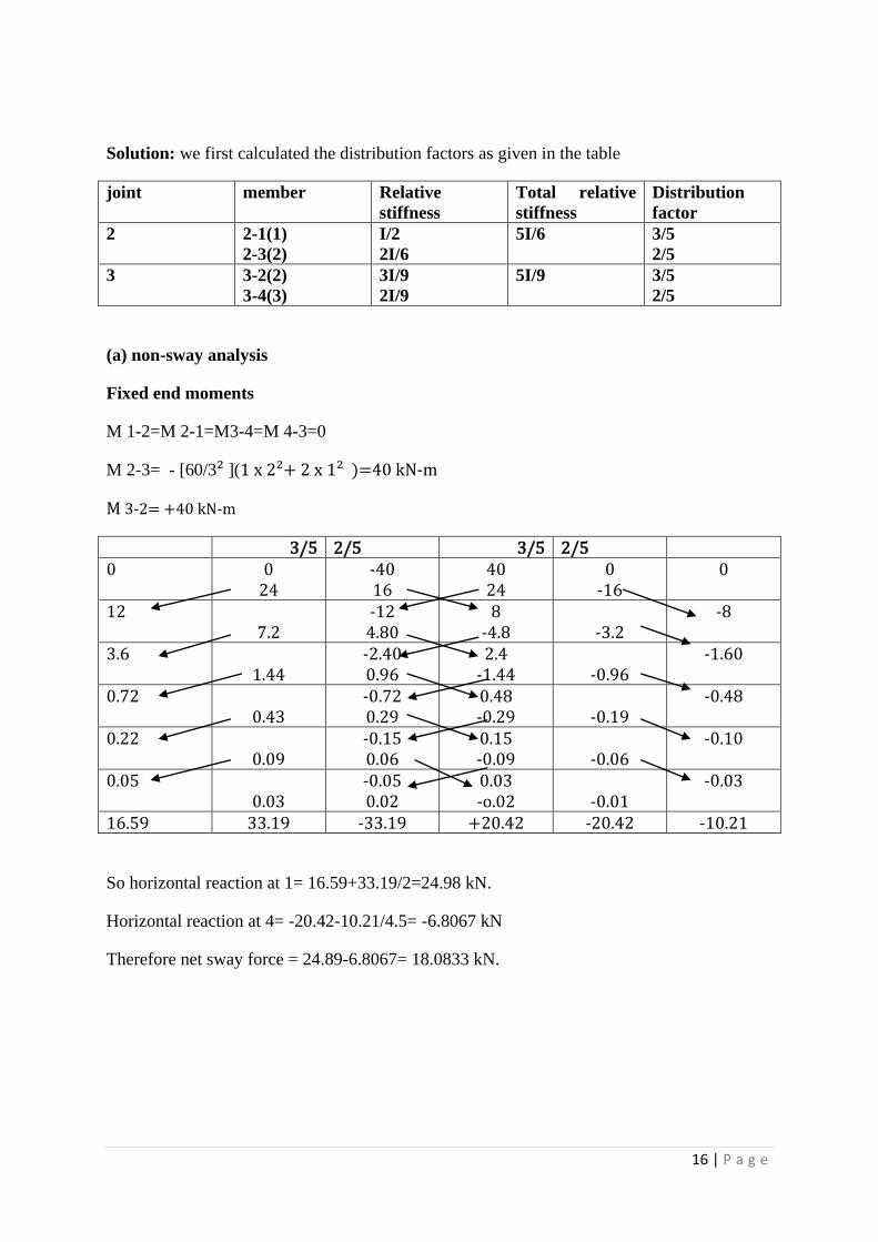
Solution: we first calculated the distribution factors as given in the table
joint member Relative
stiffness
Total relative
stiffness
Distribution
factor
2 2-1(1)
2-3(2)
I/2
2I/6
5I/6 3/5
2/5
3 3-2(2)
3-4(3)
3I/9
2I/9
5I/9 3/5
2/5
(a) non-sway analysis
Fixed end moments
M 1-2=M 2-1=M3-4=M 4-3=0
M 2-3= - [60/3² ](1 x 2²+ 2 x 1² )=40 kN-m
M 3-2= +40 kN-m
3/5 2/5 3/5 2/5 0 0
24 -40 16
40 24
0 -16
0
12 7.2
-12 4.80
8 -4.8
-3.2
-8
3.6 1.44
-2.40 0.96
2.4 -1.44
-0.96
-1.60
0.72 0.43
-0.72 0.29
0.48 -0.29
-0.19
-0.48
0.22 0.09
-0.15 0.06
0.15 -0.09
-0.06
-0.10
0.05 0.03
-0.05 0.02
0.03 -o.02
-0.01
-0.03
16.59 33.19 -33.19 +20.42 -20.42 -10.21
So horizontal reaction at 1= 16.59+33.19/2=24.98 kN.
Horizontal reaction at 4= -20.42-10.21/4.5= -6.8067 kN
Therefore net sway force = 24.89-6.8067= 18.0833 kN.
17 | P a g e
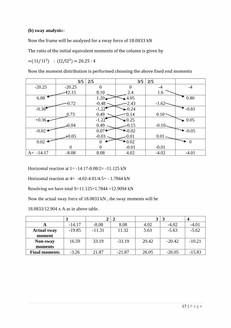
(b) sway analysis:-
Now the frame will be analysed for a sway force of 18.0833 kN
The ratio of the initial equivalent moments of the column is given by
=( I1/ l1²) : (I2/l2²) = 20.25 : 4
Now the moment distribution is performed choosing the above fixed end moments
3/5 2/5 3/5 2/5
-20.25 -20.25
12.15
0
8.10
0
2.4
-4
1.6
-4
6.08
-0.72
1.20
-0.48
4.05
-2.43
-1.62
0.80
-0.36
0.73
-1.22
0.49
-0.24
0.14
0.10
-0.81
+0.36
-0.04
-1.22
0.49
0.25
-0.15
-0.10
0.05
-0.02
+0.05
0.07
-0.03
-0.02
0.01
0.01
-0.05
0.02
0
0
0
0.02
-0.01
-0.01
0
A= -14.17 -8.08 8.08 4.02 -4.02 -4.01
Horizontal reaction at 1= -14.17-8.08/2= -11.125 kN
Horizontal reaction at 4= -4.02-4.01/4.5= - 1.7844 kN
Resolving we have total S=11.125+1.7844 =12.9094 kN
Now the actual sway force of 18.0833 kN , the sway moments will be
18.0833/12.904 x A as in above table.
1 2 2 3 3 4
A -14.17 -8.08 8.08 4.02 -4.02 -4.01
Actual sway
moment
-19.85 -11.31 11.32 5.63 -5.63 -5.62
Non-sway
moments
16.59 33.19 -33.19 20.42 -20.42 -10.21
Final moments -3.26 21.87 -21.87 26.05 -26.05 -15.83

18 | P a g e
(c) Reactions
H1=9.31 kN
H4=-9.31 kN
V4=61.39 kN
V1=120-61.39=58.61 kN.
19 | P a g e
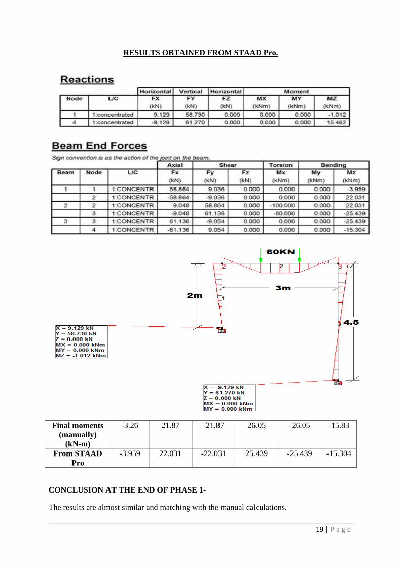
RESULTS OBTAINED FROM STAAD Pro.
Final moments
(manually)
(kN-m)
-3.26 21.87 -21.87 26.05 -26.05 -15.83
From STAAD
Pro
-3.959 22.031 -22.031 25.439 -25.439 -15.304
CONCLUSION AT THE END OF PHASE 1-
The results are almost similar and matching with the manual calculations.
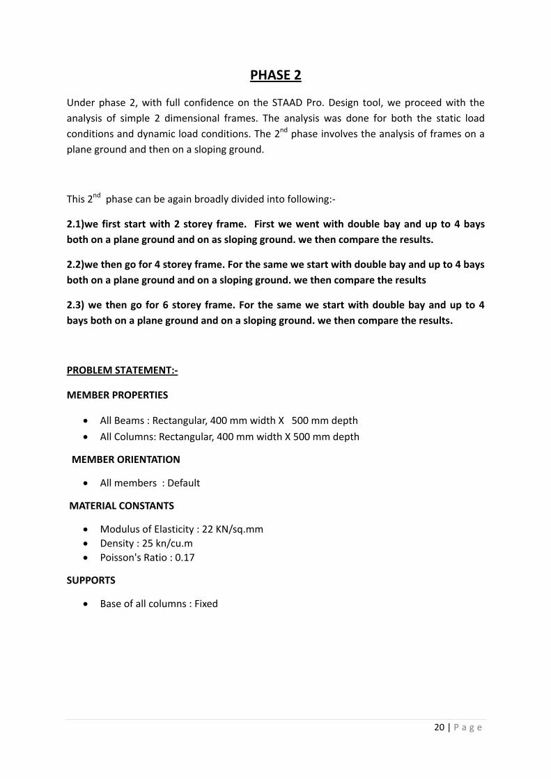
20 | P a g e
PHASE 2
Under phase 2, with full confidence on the STAAD Pro. Design tool, we proceed with the
analysis of simple 2 dimensional frames. The analysis was done for both the static load
conditions and dynamic load conditions. The 2nd phase involves the analysis of frames on a
plane ground and then on a sloping ground.
This 2nd phase can be again broadly divided into following:-
2.1)we first start with 2 storey frame. First we went with double bay and up to 4 bays
both on a plane ground and on as sloping ground. we then compare the results.
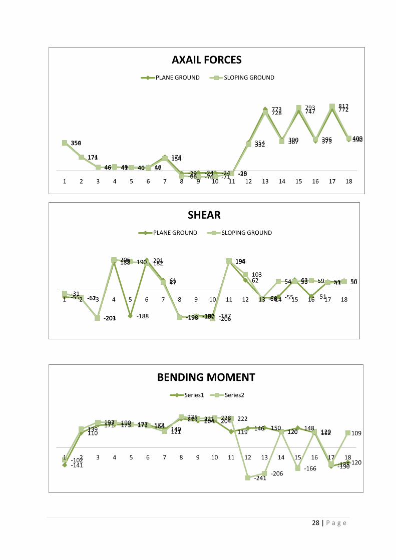
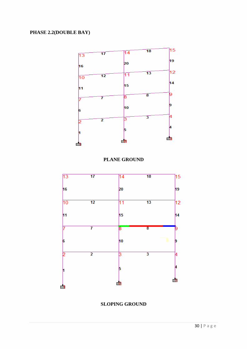
2.2)we then go for 4 storey frame. For the same we start with double bay and up to 4 bays
both on a plane ground and on a sloping ground. we then compare the results
2.3) we then go for 6 storey frame. For the same we start with double bay and up to 4
bays both on a plane ground and on a sloping ground. we then compare the results.
PROBLEM STATEMENT:-
MEMBER PROPERTIES
All Beams : Rectangular, 400 mm width X 500 mm depth
All Columns: Rectangular, 400 mm width X 500 mm depth
MEMBER ORIENTATION
All members : Default
MATERIAL CONSTANTS Modulus of Elasticity : 22 KN/sq.mm
Density : 25 kn/cu.m
Poisson's Ratio : 0.17
SUPPORTS
Base of all columns : Fixed
21 | P a g e
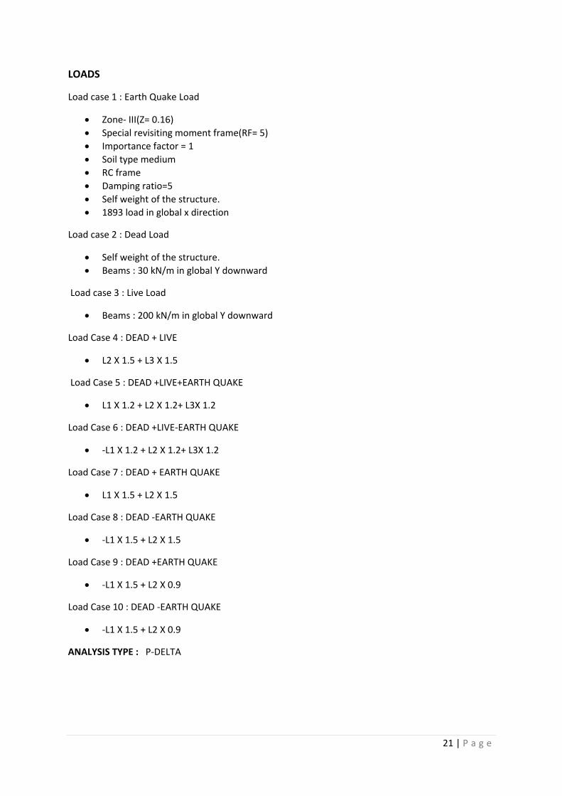
LOADS
Load case 1 : Earth Quake Load
Zone- III(Z= 0.16)
Special revisiting moment frame(RF= 5)
Importance factor = 1
Soil type medium
RC frame
Damping ratio=5
Self weight of the structure.
1893 load in global x direction
Load case 2 : Dead Load
Self weight of the structure.
Beams : 30 kN/m in global Y downward
Load case 3 : Live Load
Beams : 200 kN/m in global Y downward
Load Case 4 : DEAD + LIVE
L2 X 1.5 + L3 X 1.5
Load Case 5 : DEAD +LIVE+EARTH QUAKE
L1 X 1.2 + L2 X 1.2+ L3X 1.2
Load Case 6 : DEAD +LIVE-EARTH QUAKE
-L1 X 1.2 + L2 X 1.2+ L3X 1.2
Load Case 7 : DEAD + EARTH QUAKE
L1 X 1.5 + L2 X 1.5
Load Case 8 : DEAD -EARTH QUAKE
-L1 X 1.5 + L2 X 1.5
Load Case 9 : DEAD +EARTH QUAKE
-L1 X 1.5 + L2 X 0.9
Load Case 10 : DEAD -EARTH QUAKE
-L1 X 1.5 + L2 X 0.9
ANALYSIS TYPE : P-DELTA
22 | P a g e
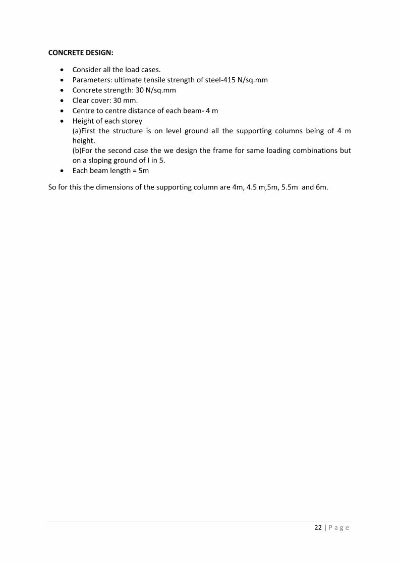
CONCRETE DESIGN:
Consider all the load cases.
Parameters: ultimate tensile strength of steel-415 N/sq.mm
Concrete strength: 30 N/sq.mm
Clear cover: 30 mm.
Centre to centre distance of each beam- 4 m
Height of each storey (a)First the structure is on level ground all the supporting columns being of 4 m height. (b)For the second case the we design the frame for same loading combinations but on a sloping ground of I in 5.
Each beam length = 5m
So for this the dimensions of the supporting column are 4m, 4.5 m,5m, 5.5m and 6m.
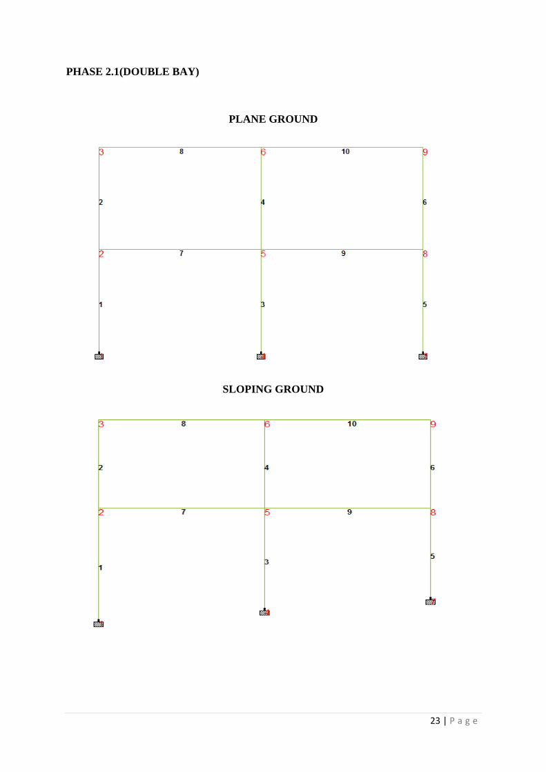
23 | P a g e
PHASE 2.1(DOUBLE BAY)
PLANE GROUND
SLOPING GROUND
24 | P a g e
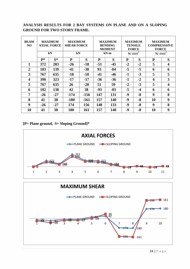
ANALYSIS RESULTS FOR 2 BAY SYSTEMS ON PLANE AND ON A SLOPING
GROUND FOR TWO STORY FRAME.
BEAM
NO
MAXIMUM
AXIAL FORCE
MAXIMUM
SHEAR FORCE
MAXIMUM
BENDING
MOMENT
MAXIMUM
TENSILE
FORCE
MAXIMUM
COMPRESSSIVE
FORCE
kN kN kN-m N/ mm2 N/ mm
2
P* S* P S P S P S P S
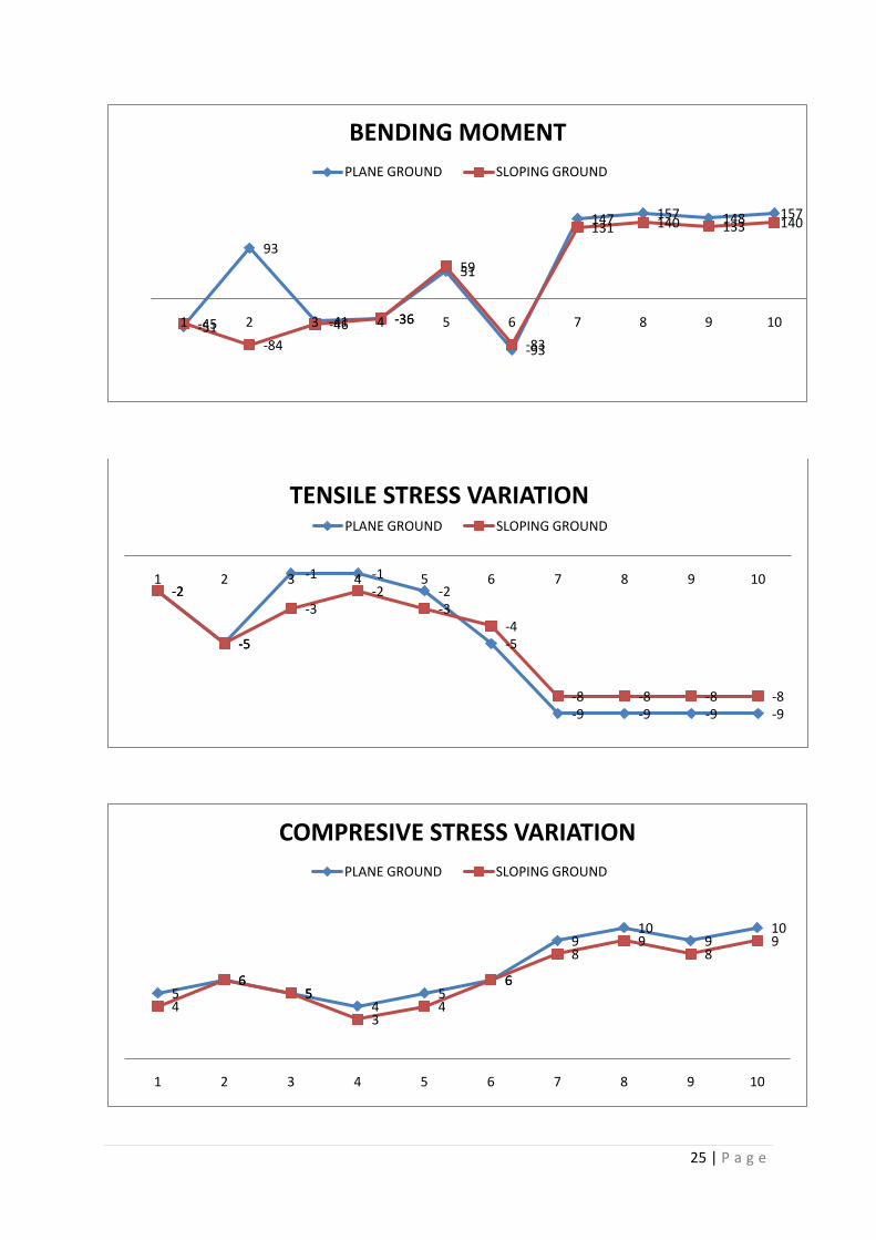
1 372 283 -26 -18 -51 -45 -2 -2 5 4
2 183 139 -41 -38 93 -84 -5 -5 6 6
3 767 635 -18 -18 -41 -46 -1 -3 5 5
4 390 323 -17 -17 -36 -36 -1 -2 4 3
5 767 635 26 -28 51 59 -2 -3 5 4
6 182 138 42 38 -93 -83 -5 -4 6 6
7 -26 -27 -174 -156 147 131 -9 -8 9 8
8 41 38 -180 -161 157 140 -9 -8 10 9
9 -26 -27 174 156 148 133 -9 -8 9 8
10 41 38 180 161 157 140 -9 -8 10 9
[P= Plane ground, S= Sloping Ground]*
0
372183
767
390 372182
-26 41 -26 410
283139
635
323 282138
-27 38 -27 38
1 2 3 4 5 6 7 8 9 10 11
AXIAL FORCES
PLANE GROUND SLOPING GROUND
-26 -41 -18 -1726 42
-174 -180
174 180
-18-38
-18 -17-28
38
-156 -161
156 161
1 2 3 4 5 6 7 8 9 10
MAXIMUM SHEAR
PLANE GROUND SLOPING GROUND
25 | P a g e
-51
93
-41 -36
51
-93
147 157 148 157
-45
-84
-46 -36
59
-83
131 140 133 140
1 2 3 4 5 6 7 8 9 10
BENDING MOMENT
PLANE GROUND SLOPING GROUND
-2
-5
-1 -1-2
-5
-9 -9 -9 -9
-2
-5
-3-2
-3-4
-8 -8 -8 -8
1 2 3 4 5 6 7 8 9 10
TENSILE STRESS VARIATIONPLANE GROUND SLOPING GROUND
56
54
56
910
910
4
65
34
6
89
89
1 2 3 4 5 6 7 8 9 10
COMPRESIVE STRESS VARIATION
PLANE GROUND SLOPING GROUND
26 | P a g e
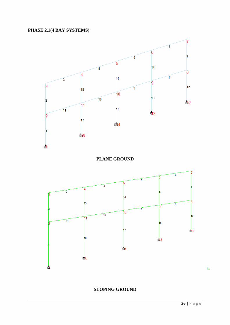
PHASE 2.1(4 BAY SYSTEMS)
PLANE GROUND
SLOPING GROUND
27 | P a g e
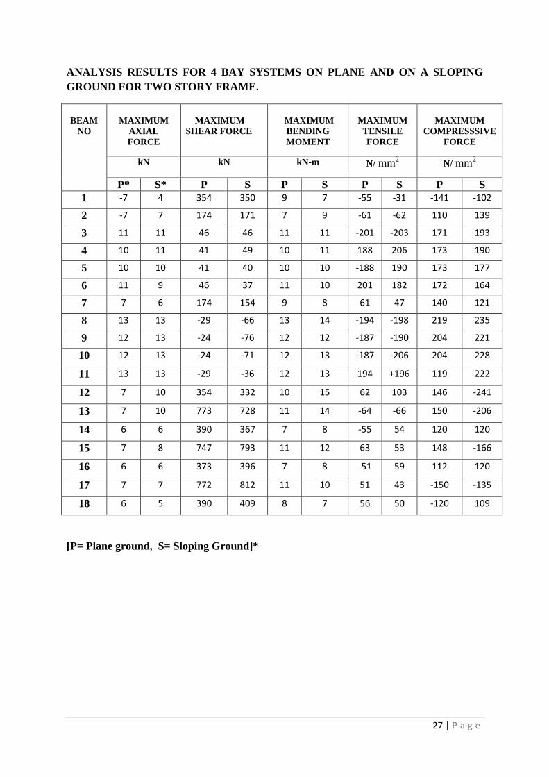
ANALYSIS RESULTS FOR 4 BAY SYSTEMS ON PLANE AND ON A SLOPING
GROUND FOR TWO STORY FRAME.
BEAM
NO
MAXIMUM
AXIAL
FORCE
MAXIMUM
SHEAR FORCE
MAXIMUM
BENDING
MOMENT
MAXIMUM
TENSILE
FORCE
MAXIMUM
COMPRESSSIVE
FORCE
kN kN kN-m N/ mm2 N/ mm
2
P* S* P S P S P S P S
1 -7 4 354 350 9 7 -55 -31 -141 -102
2 -7 7 174 171 7 9 -61 -62 110 139
3 11 11 46 46 11 11 -201 -203 171 193
4 10 11 41 49 10 11 188 206 173 190
5 10 10 41 40 10 10 -188 190 173 177
6 11 9 46 37 11 10 201 182 172 164
7 7 6 174 154 9 8 61 47 140 121
8 13 13 -29 -66 13 14 -194 -198 219 235
9 12 13 -24 -76 12 12 -187 -190 204 221
10 12 13 -24 -71 12 13 -187 -206 204 228
11 13 13 -29 -36 12 13 194 +196 119 222
12 7 10 354 332 10 15 62 103 146 -241
13 7 10 773 728 11 14 -64 -66 150 -206
14 6 6 390 367 7 8 -55 54 120 120
15 7 8 747 793 11 12 63 53 148 -166
16 6 6 373 396 7 8 -51 59 112 120
17 7 7 772 812 11 10 51 43 -150 -135
18 6 5 390 409 8 7 56 50 -120 109
[P= Plane ground, S= Sloping Ground]*
28 | P a g e
354
174
46 41 41 46
174
-29 -24 -24 -29
354
773
390
747
373
772
390350
171
46 49 40 37
154
-66 -76 -71 -36
332
728
367
793
396
812
409
1 2 3 4 5 6 7 8 9 10 11 12 13 14 15 16 17 18
AXAIL FORCES
PLANE GROUND SLOPING GROUND
-55 -61
-201
188
-188
201
61
-194 -187 -187
194
62
-64 -55
63
-51
51 56
-31-62
-203
206 190 182
47
-198 -190 -206
196
103
-66
54 53 59 43 50
1 2 3 4 5 6 7 8 9 10 11 12 13 14 15 16 17 18
SHEAR
PLANE GROUND SLOPING GROUND
-141
110171 173 173 172
140
219 204 204
119146 150
120148
112
-150-120-102
139193 190 177 164
121
235 221 228 222
-241-206
120
-166
120
-135
109
1 2 3 4 5 6 7 8 9 10 11 12 13 14 15 16 17 18
BENDING MOMENT
Series1 Series2
29 | P a g e
97
11 10 10 119
13 12 12 1210 11
7
11
7
11
879
11 11 10 108
1412 13 13
15 14
8
12
810
7
1 2 3 4 5 6 7 8 9 10 11 12 13 14 15 16 17 18
COMPRESSIVE STRESS
PLANE GROUND SLOPING GROUND
7 7
1110 10
11
7
1312 12
13
7 76
76
76
4
7
11 1110
9
6
13 13 13 13
10 10
6
8
67
5
1 2 3 4 5 6 7 8 9 10 11 12 13 14 15 16 17 18
TENSILE STRESS
PLANE GROUND SLOPING GROUND
30 | P a g e
PHASE 2.2(DOUBLE BAY)
PLANE GROUND
SLOPING GROUND
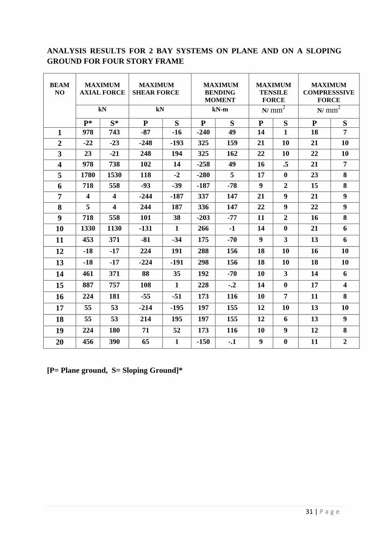
31 | P a g e
ANALYSIS RESULTS FOR 2 BAY SYSTEMS ON PLANE AND ON A SLOPING
GROUND FOR FOUR STORY FRAME
BEAM
NO
MAXIMUM
AXIAL FORCE
MAXIMUM
SHEAR FORCE
MAXIMUM
BENDING
MOMENT
MAXIMUM
TENSILE
FORCE
MAXIMUM
COMPRESSSIVE
FORCE
kN kN kN-m N/ mm2 N/ mm
2
P* S* P S P S P S P S
1 978 743 -87 -16 -240 49 14 1 18 7
2 -22 -23 -248 -193 325 159 21 10 21 10
3 23 -21 248 194 325 162 22 10 22 10
4 978 738 102 14 -258 49 16 .5 21 7
5 1780 1530 118 -2 -280 5 17 0 23 8
6 718 558 -93 -39 -187 -78 9 2 15 8
7 4 4 -244 -187 337 147 21 9 21 9
8 5 4 244 187 336 147 22 9 22 9
9 718 558 101 38 -203 -77 11 2 16 8
10 1330 1130 -131 1 266 -1 14 0 21 6
11 453 371 -81 -34 175 -70 9 3 13 6
12 -18 -17 224 191 288 156 18 10 16 10
13 -18 -17 -224 -191 298 156 18 10 18 10
14 461 371 88 35 192 -70 10 3 14 6
15 887 757 108 1 228 -.2 14 0 17 4
16 224 181 -55 -51 173 116 10 7 11 8
17 55 53 -214 -195 197 155 12 10 13 10
18 55 53 214 195 197 155 12 6 13 9
19 224 180 71 52 173 116 10 9 12 8
20 456 390 65 1 -150 -.1 9 0 11 2
[P= Plane ground, S= Sloping Ground]*
32 | P a g e
-87
-248
248
102 118
-93
-244
244
101
-131-81
224
-224
88 108
-55
-214
214
71
-16
-193
194
14 -2-39
-187
187
381
-34
191
-191
351
-51
-195
195
521
1 2 3 4 5 6 7 8 9 10 11 12 13 14 15 16 17 18 19 20
SHEAR
PLANE GROUND SLOPING GROUND
1821 22 21
23
15
21 22
16
21
1316
18
1417
1113 13 12 11
710 10
7 8 8 9 9 86 6
10 10
64
810 9 8
2
1 2 3 4 5 6 7 8 9 10 11 12 13 14 15 16 17 18 19 20
COMPRESSIVE STRESS
PLANE GROUND SLOPING GROUND
14
21 22
16 17
9
21 22
11
14
9
18 18
10
14
1012 12
10 9
1
10 10
0.5 02
9 9
20
3
10 10
3
0
7
10
6
9
0
1 2 3 4 5 6 7 8 9 10 11 12 13 14 15 16 17 18 19 20
TENSILE STRESS
PLANE GROUND SLOPING GROUND
33 | P a g e
-240
325 325
-258 -280
-187
337 336
-203
266
175
288 298
192228
173 197 197 173
-150
49
159 162
495
-78
147 147
-77
-1-70
156 156
-70-0.2
116155 155
116
-0.1
1 2 3 4 5 6 7 8 9 10 11 12 13 14 15 16 17 18 19 20
BENDING MOMENT
PLANE GROUND SLOPING GROUND
978
-22 23
978
1780
718
4 5
718
1330
453
-18 -18
461
887
22455 55
224456
743
-23 -21
738
1530
558
4 4
558
1130
371
-17 -17
371
757
18153 53
180390
1 2 3 4 5 6 7 8 9 10 11 12 13 14 15 16 17 18 19 20
AXIAL FORCE
PLANE GROUND SLOPING GROUND
34 | P a g e
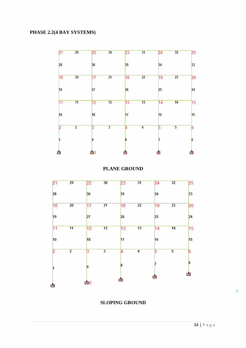
PHASE 2.2(4 BAY SYSTEMS)
PLANE GROUND
SLOPING GROUND
35 | P a g e
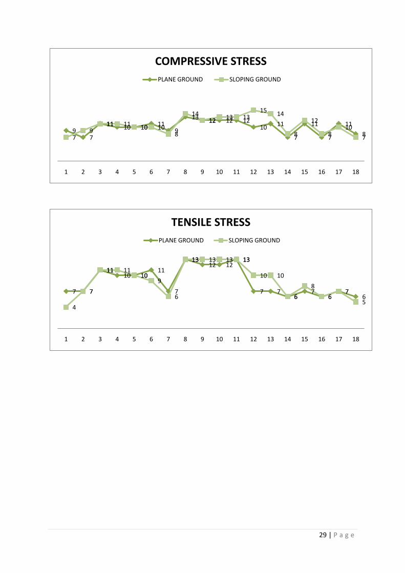
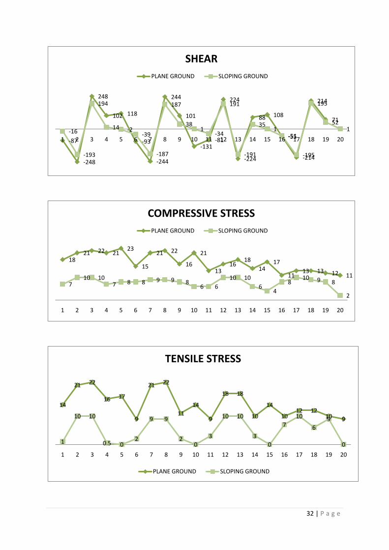
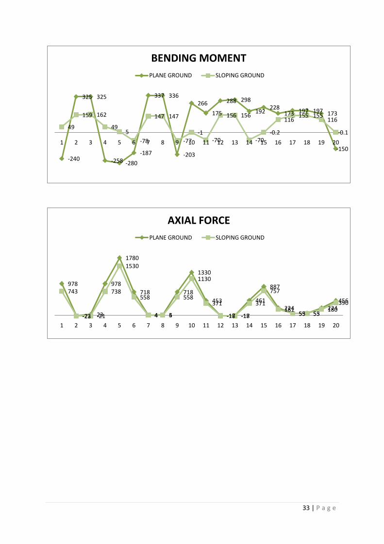
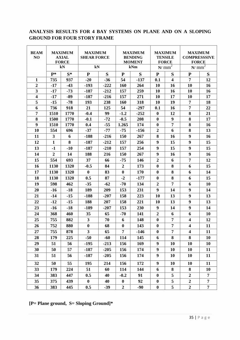
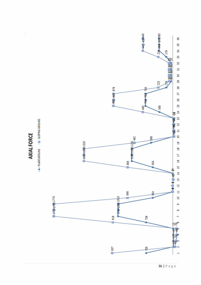
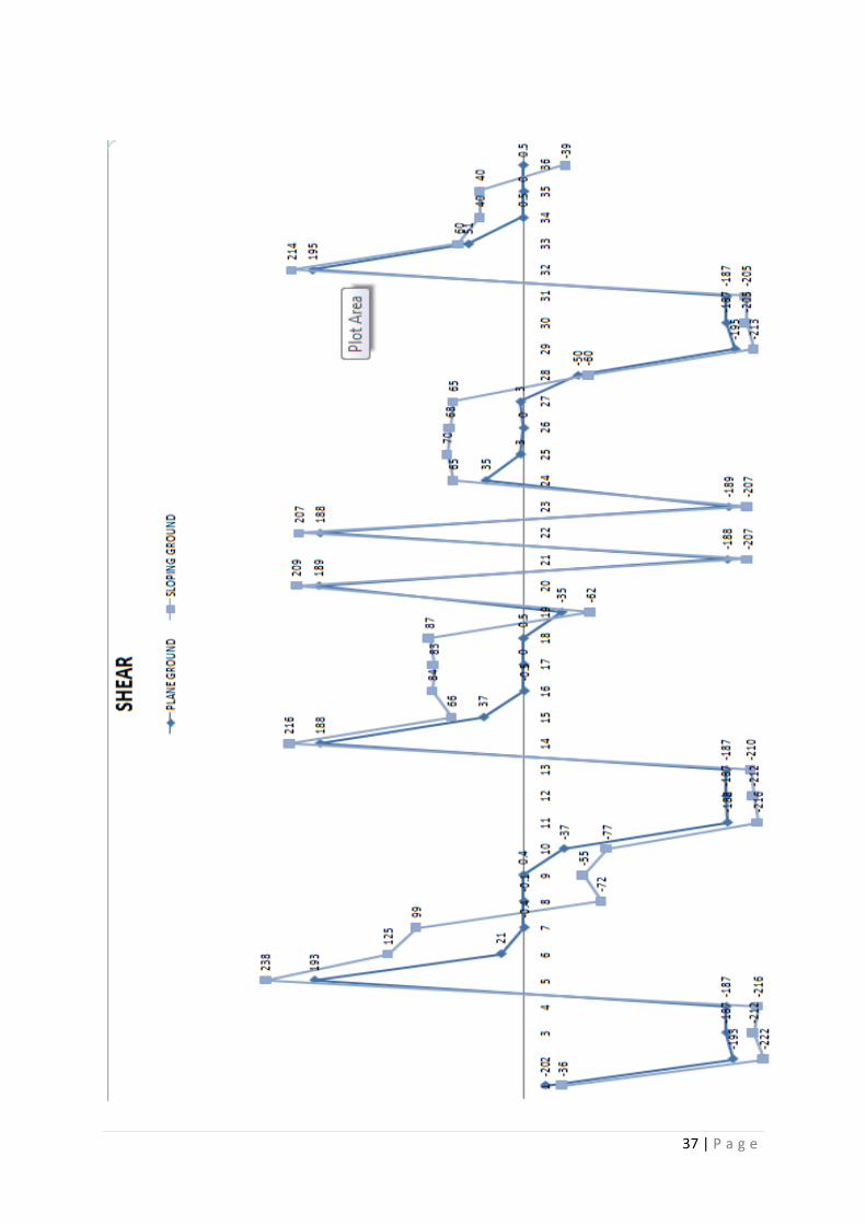
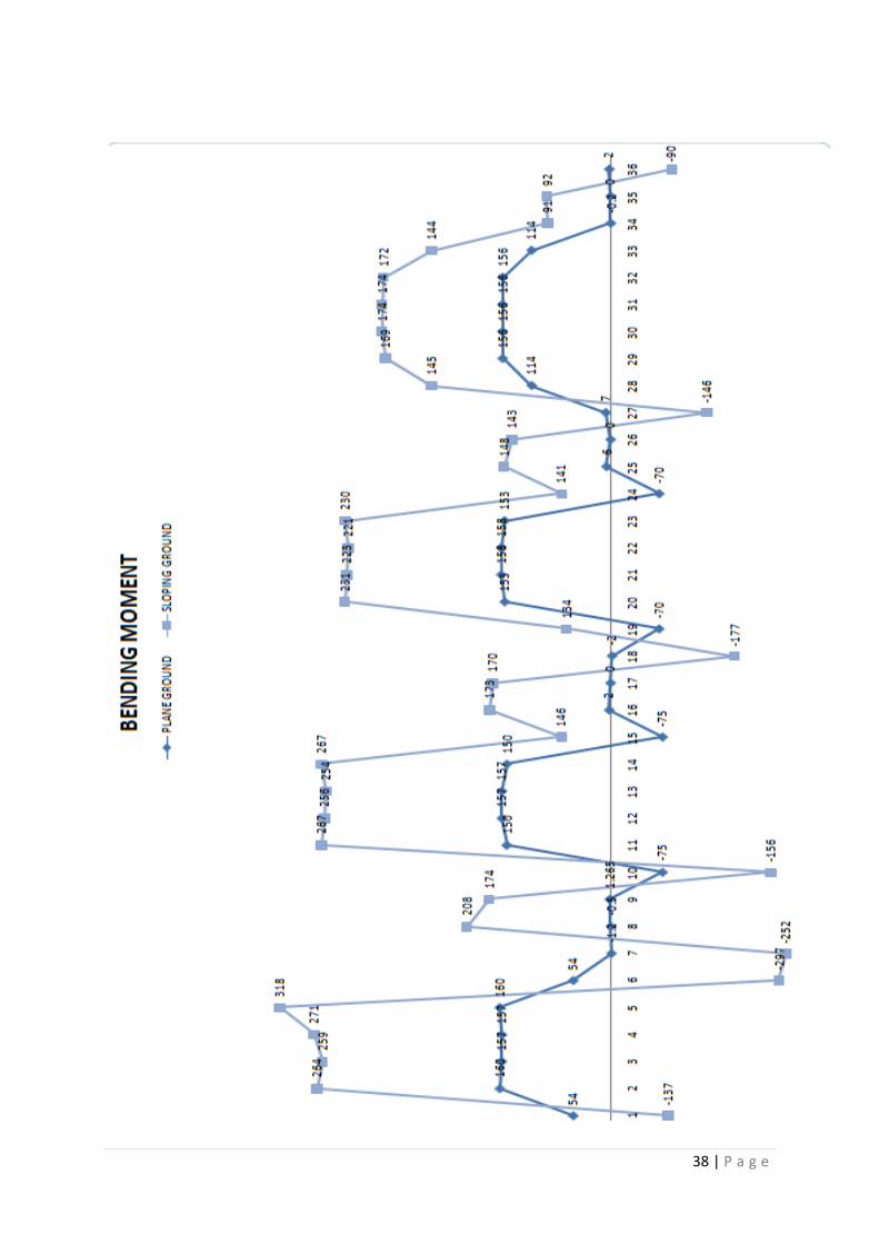
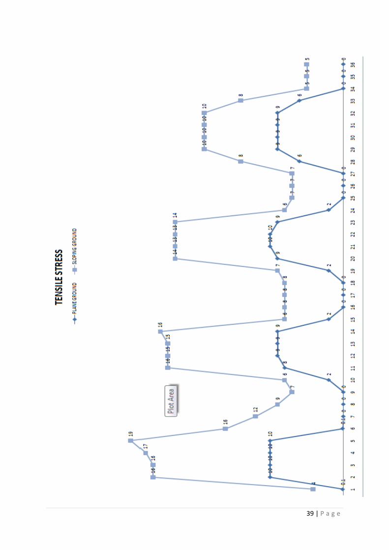
ANALYSIS RESULTS FOR 4 BAY SYSTEMS ON PLANE AND ON A SLOPING
GROUND FOR FOUR STORY FRAME
BEAM
NO
MAXIMUM
AXIAL
FORCE
MAXIMUM
SHEAR FORCE
MAXIMUM
BENDING
MOMENT
MAXIMUM
TENSILE
FORCE
MAXIMUM
COMPRESSSIVE
FORCE
kN kN kNm N/ mm2 N/ mm
2
P* S* P S P S P S P S 1 735 937 -20 -36 54 -137 0.1 4 7 12
2 -17 -43 -193 -222 160 264 10 16 10 16
3 -17 -73 -187 -212 157 259 10 16 10 16
4 -17 -89 -187 -216 157 271 10 17 10 17
5 -15 -78 193 238 160 318 10 19 7 18
6 736 918 21 125 54 -297 0.1 16 7 22
7 1510 1770 -0.4 99 -1.2 -252 0 12 8 21
8 1500 1770 -0.1 -72 -0.5 208 0 9 8 17
9 1510 1770 0.4 -55 1.265 174 0 7 8 16
10 554 696 -37 -77 -75 -156 2 6 8 13
11 3 6 -188 -216 150 267 8 16 9 16
12 1 8 -187 -212 157 256 9 15 9 15
13 -1 -10 -187 -210 157 254 9 15 9 15
14 2 14 188 216 150 267 9 16 9 16
15 554 693 37 66 -75 146 2 6 7 12
16 1130 1320 -0.5 84 2 173 0 8 6 15
17 1130 1320 0 83 0 170 0 8 6 14
18 1130 1320 0.5 87 -2 -177 0 8 6 15
19 598 462 -35 -62 -70 134 2 7 6 10
20 -16 -18 189 209 153 231 9 14 9 14
21 -14 -15 -188 -207 158 223 10 13 9 13
22 -12 -15 188 207 158 221 10 13 9 13
23 -16 -18 -189 -207 153 230 9 14 9 14
24 368 460 35 65 -70 141 2 6 6 10
25 755 882 3 70 6 148 0 7 4 12
26 752 880 0 68 0 143 0 7 4 11
27 755 878 3 65 7 -146 0 7 4 11
28 179 225 -50 -60 114 145 6 8 8 10
29 51 56 -195 -213 156 169 9 10 10 10
30 50 57 -187 -205 156 174 9 10 10 11
31 51 56 -187 -205 156 174 9 10 10 11
32 50 55 195 214 156 172 9 10 10 11
33 179 224 51 60 114 144 6 8 8 10
34 383 447 0.5 40 -0.2 91 0 5 2 7
35 375 439 0 40 0 92 0 5 2 7
36 383 445 0.5 -39 2 -90 0 5 2 7
[P= Plane ground, S= Sloping Ground]*
36 | P a g e
37 | P a g e
38 | P a g e
39 | P a g e
40 | P a g e
41 | P a g e
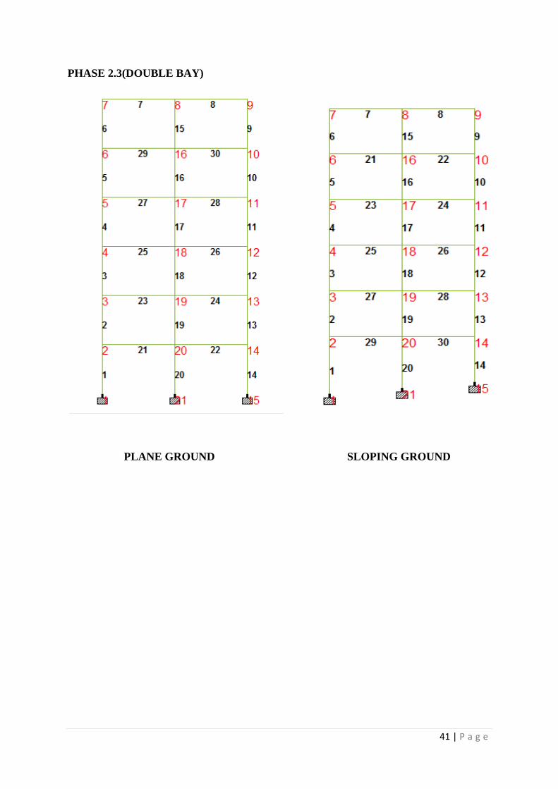
PHASE 2.3(DOUBLE BAY)
PLANE GROUND SLOPING GROUND
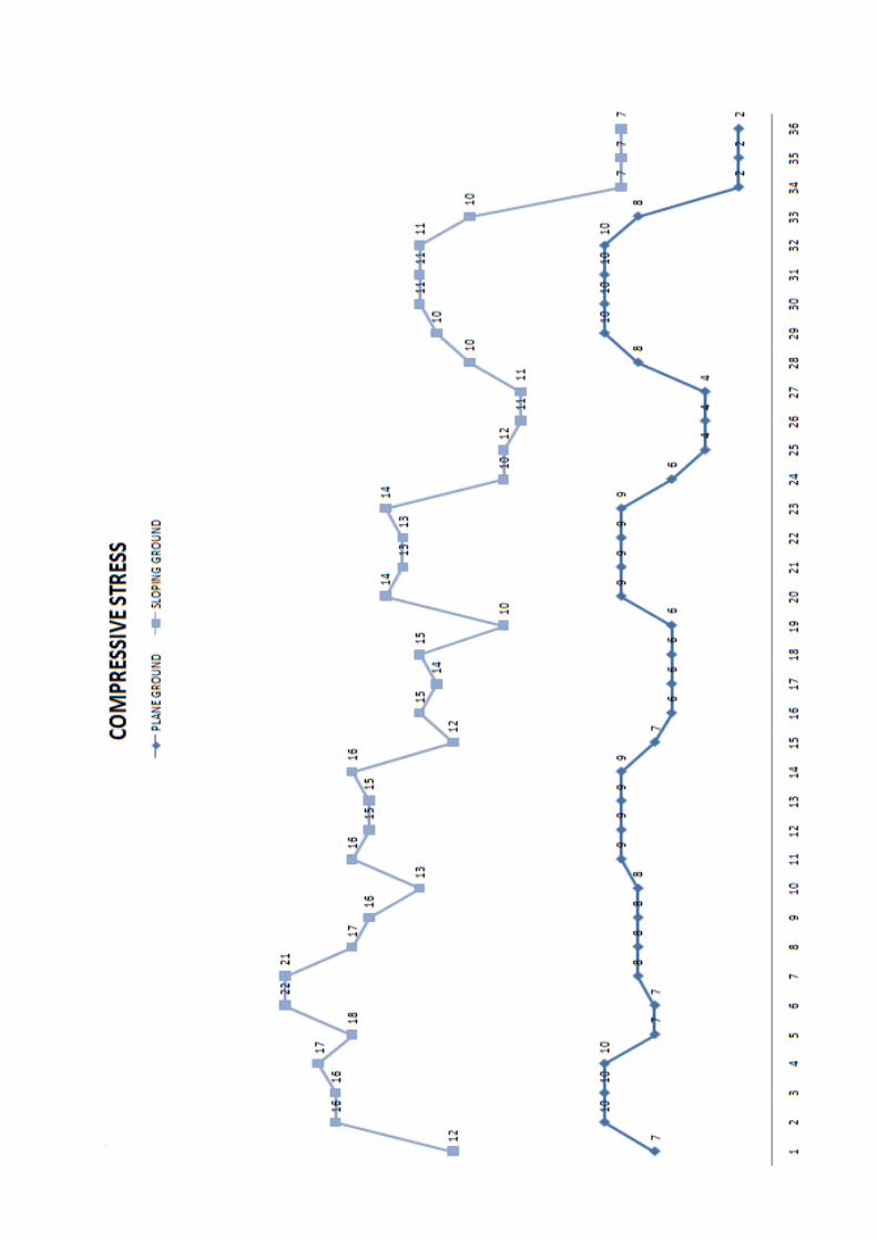
42 | P a g e
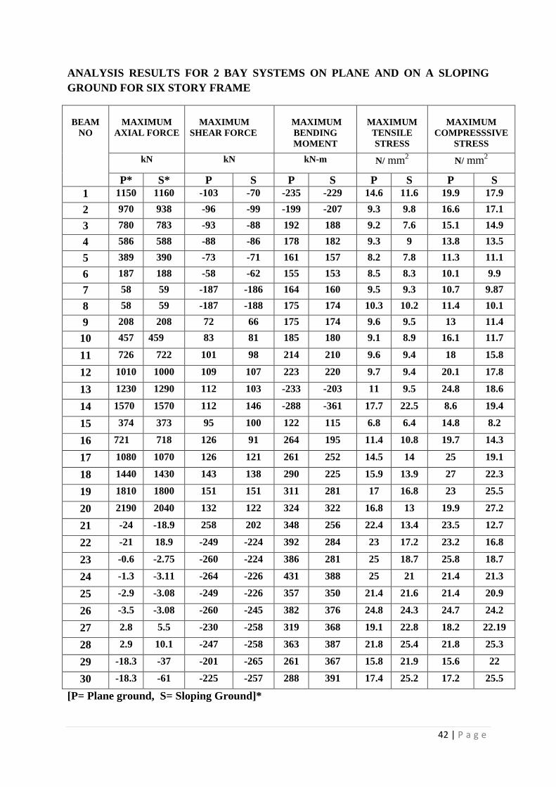
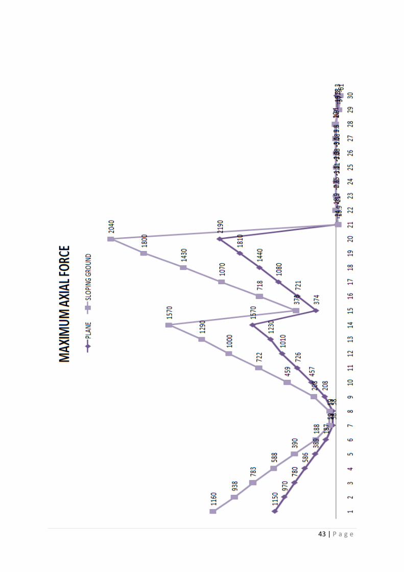
ANALYSIS RESULTS FOR 2 BAY SYSTEMS ON PLANE AND ON A SLOPING
GROUND FOR SIX STORY FRAME
BEAM
NO
MAXIMUM
AXIAL FORCE
MAXIMUM
SHEAR FORCE
MAXIMUM
BENDING
MOMENT
MAXIMUM
TENSILE
STRESS
MAXIMUM
COMPRESSSIVE
STRESS
kN kN kN-m N/ mm2 N/ mm
2
P* S* P S P S P S P S
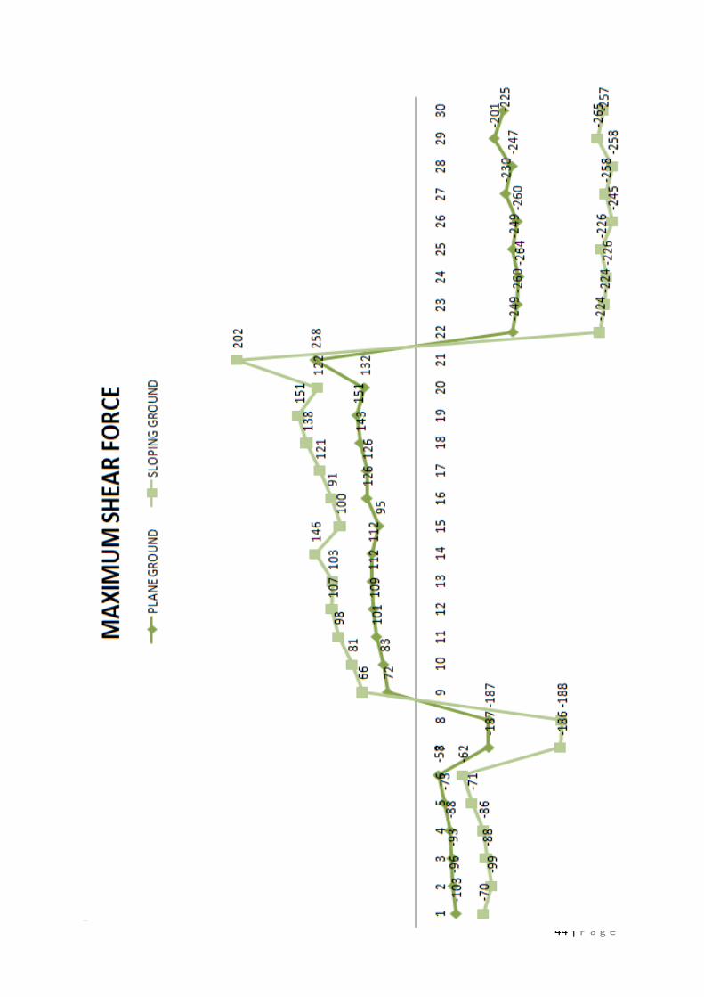
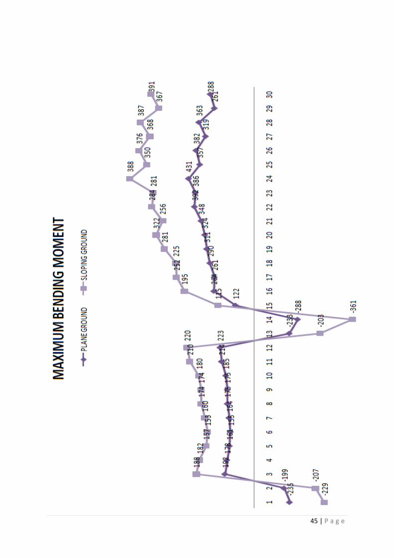
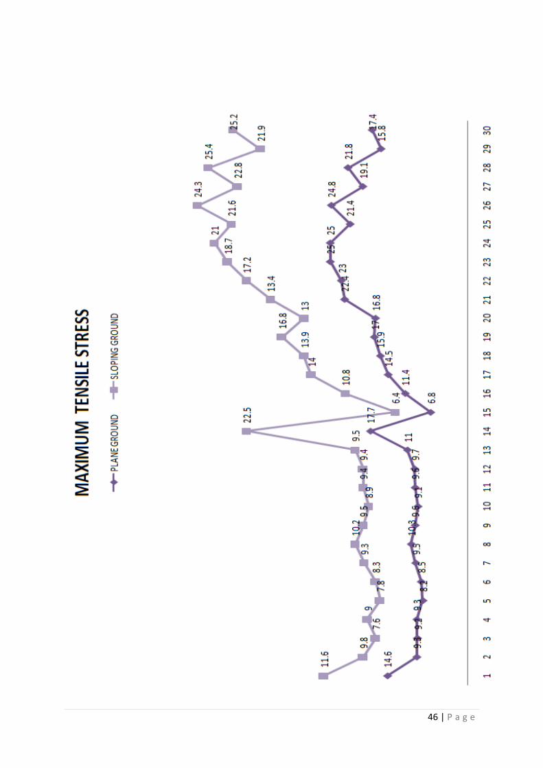
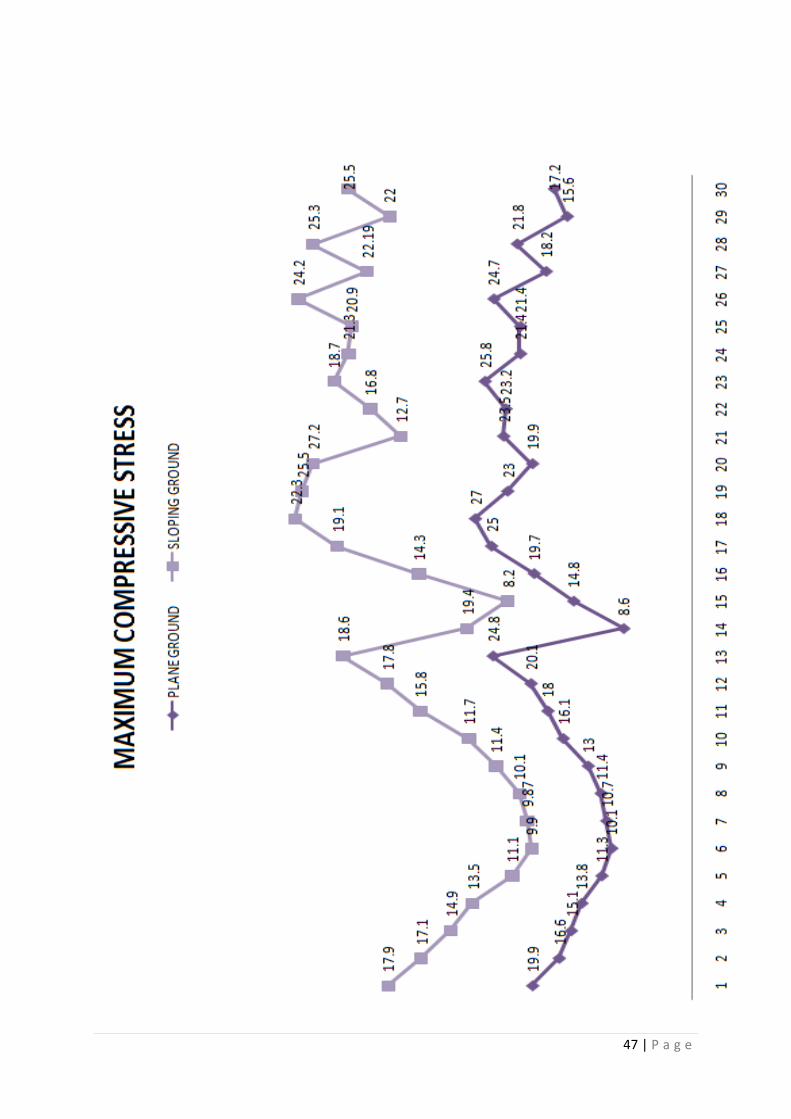
1 1150 1160 -103 -70 -235 -229 14.6 11.6 19.9 17.9
2 970 938 -96 -99 -199 -207 9.3 9.8 16.6 17.1
3 780 783 -93 -88 192 188 9.2 7.6 15.1 14.9
4 586 588 -88 -86 178 182 9.3 9 13.8 13.5
5 389 390 -73 -71 161 157 8.2 7.8 11.3 11.1
6 187 188 -58 -62 155 153 8.5 8.3 10.1 9.9
7 58 59 -187 -186 164 160 9.5 9.3 10.7 9.87
8 58 59 -187 -188 175 174 10.3 10.2 11.4 10.1
9 208 208 72 66 175 174 9.6 9.5 13 11.4
10 457 459 83 81 185 180 9.1 8.9 16.1 11.7
11 726 722 101 98 214 210 9.6 9.4 18 15.8
12 1010 1000 109 107 223 220 9.7 9.4 20.1 17.8
13 1230 1290 112 103 -233 -203 11 9.5 24.8 18.6
14 1570 1570 112 146 -288 -361 17.7 22.5 8.6 19.4
15 374 373 95 100 122 115 6.8 6.4 14.8 8.2
16 721 718 126 91 264 195 11.4 10.8 19.7 14.3
17 1080 1070 126 121 261 252 14.5 14 25 19.1
18 1440 1430 143 138 290 225 15.9 13.9 27 22.3
19 1810 1800 151 151 311 281 17 16.8 23 25.5
20 2190 2040 132 122 324 322 16.8 13 19.9 27.2
21 -24 -18.9 258 202 348 256 22.4 13.4 23.5 12.7
22 -21 18.9 -249 -224 392 284 23 17.2 23.2 16.8
23 -0.6 -2.75 -260 -224 386 281 25 18.7 25.8 18.7
24 -1.3 -3.11 -264 -226 431 388 25 21 21.4 21.3
25 -2.9 -3.08 -249 -226 357 350 21.4 21.6 21.4 20.9
26 -3.5 -3.08 -260 -245 382 376 24.8 24.3 24.7 24.2
27 2.8 5.5 -230 -258 319 368 19.1 22.8 18.2 22.19
28 2.9 10.1 -247 -258 363 387 21.8 25.4 21.8 25.3
29 -18.3 -37 -201 -265 261 367 15.8 21.9 15.6 22
30 -18.3 -61 -225 -257 288 391 17.4 25.2 17.2 25.5
[P= Plane ground, S= Sloping Ground]*
43 | P a g e
44 | P a g e
45 | P a g e
46 | P a g e
47 | P a g e
48 | P a g e
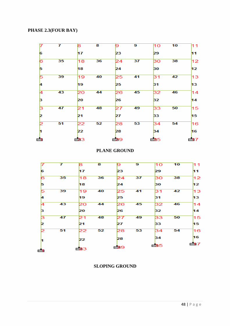
PHASE 2.3(FOUR BAY)
PLANE GROUND
SLOPING GROUND
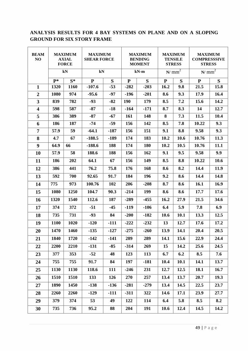
49 | P a g e
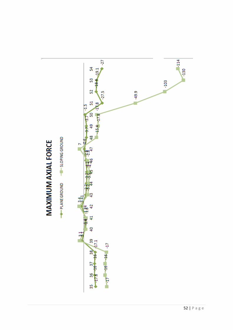
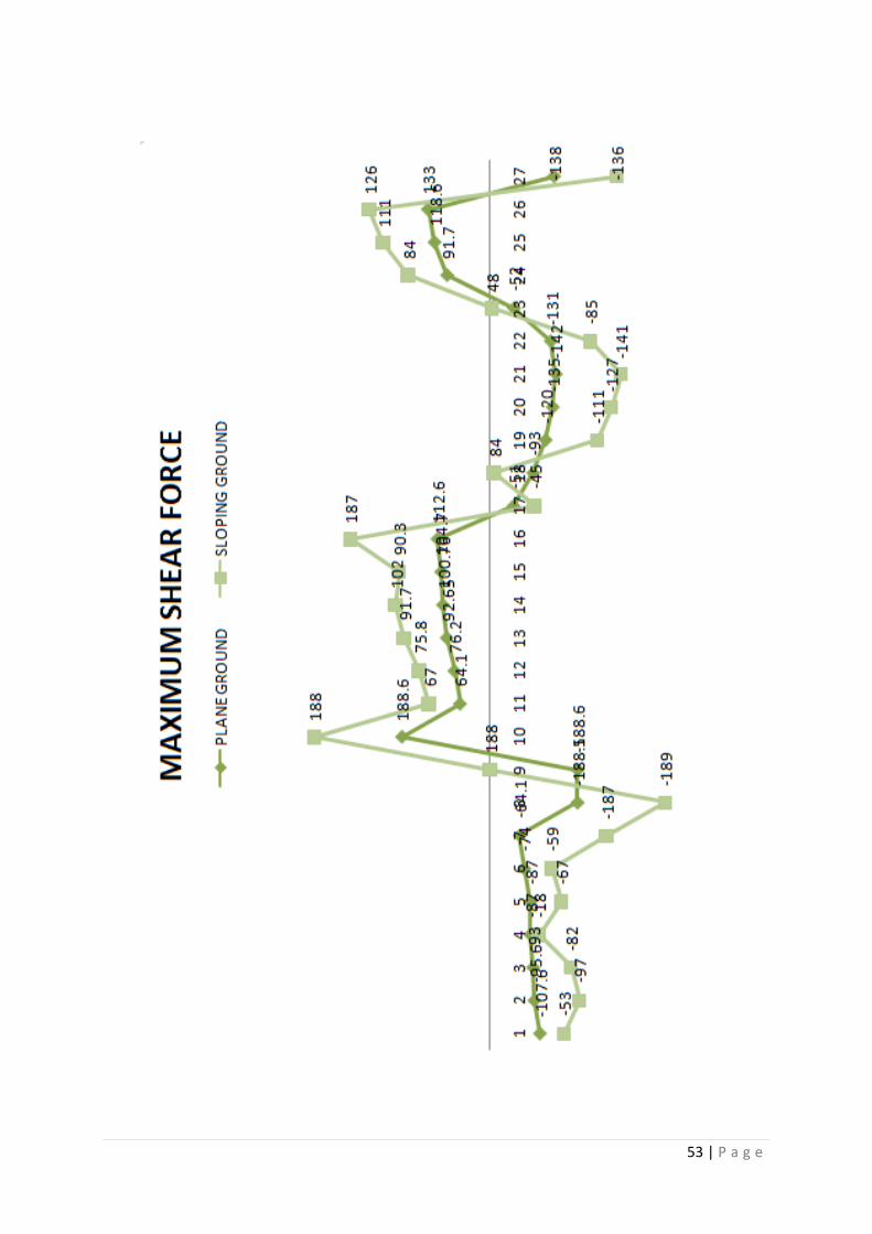
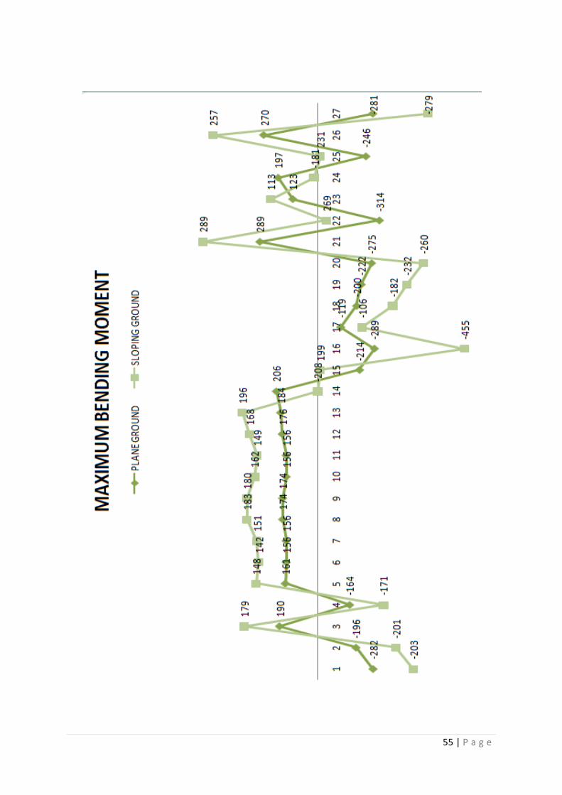
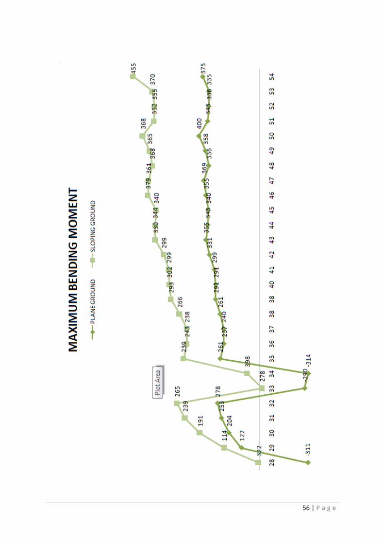
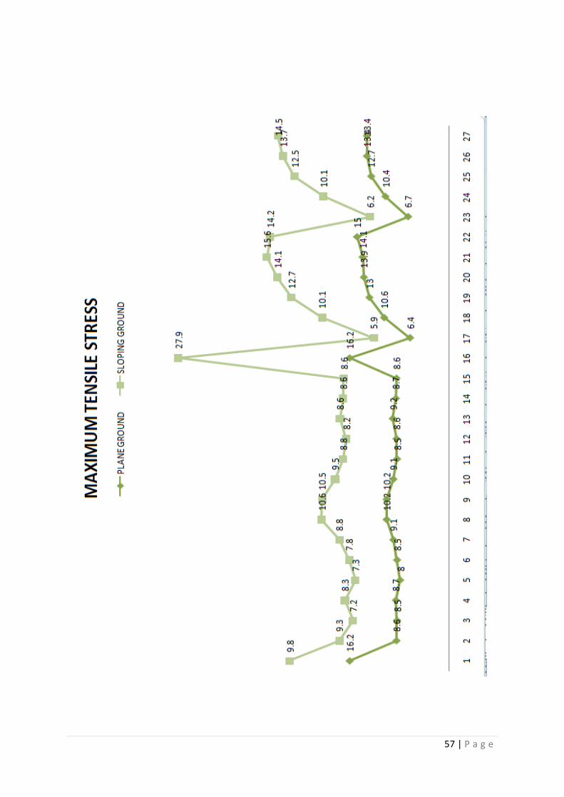
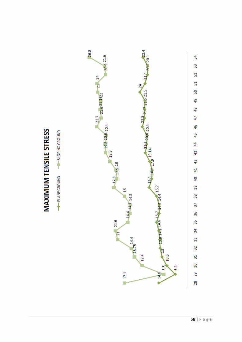
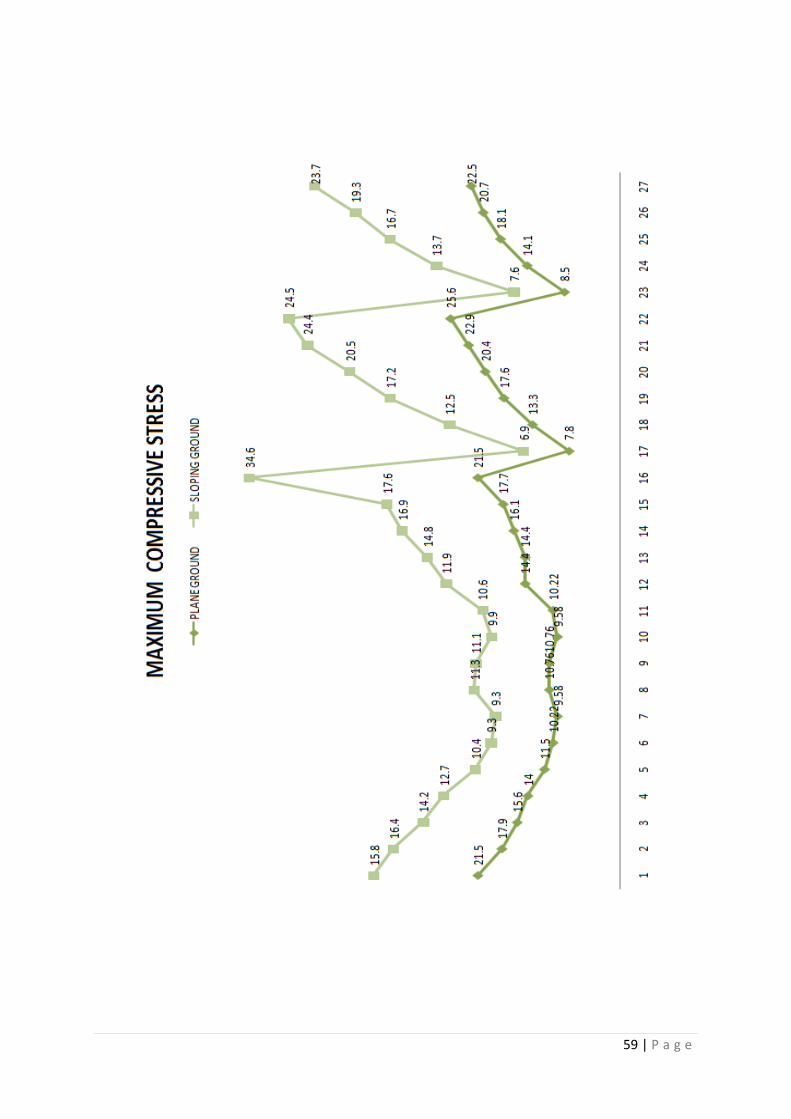
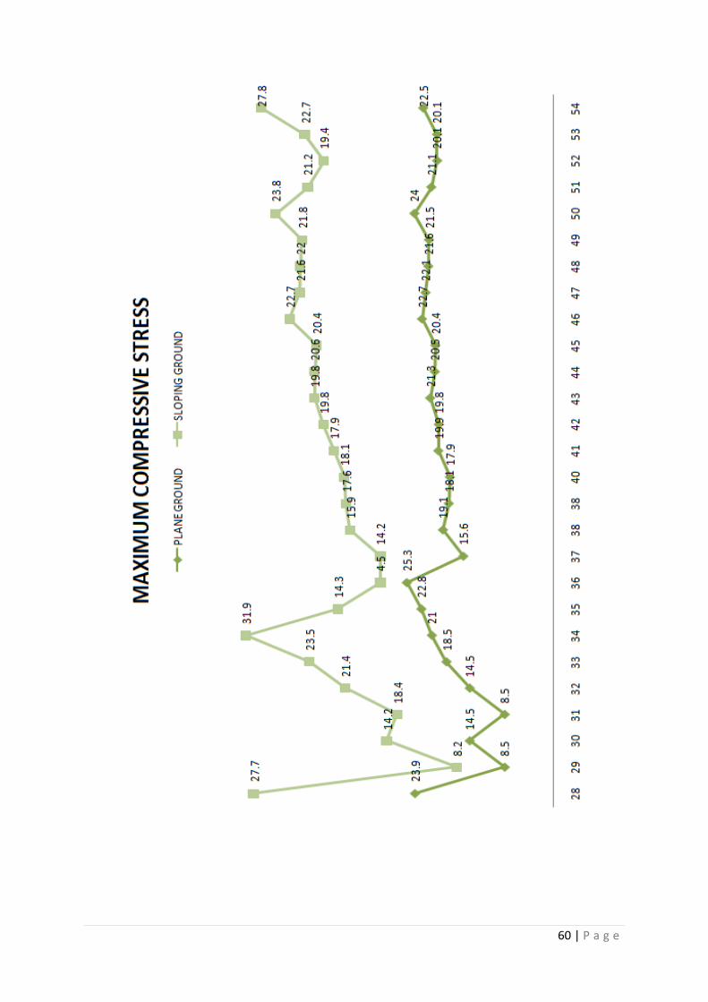
ANALYSIS RESULTS FOR 4 BAY SYSTEMS ON PLANE AND ON A SLOPING
GROUND FOR SIX STORY FRAME
BEAM
NO
MAXIMUM
AXIAL
FORCE
MAXIMUM
SHEAR FORCE
MAXIMUM
BENDING
MOMENT
MAXIMUM
TENSILE
STRESS
MAXIMUM
COMPRESSSIVE
STRESS
kN kN kN-m N/ mm2 N/ mm
2
P* S* P S P S P S P S
1 1320 1160 -107.6 -53 -282 -203 16.2 9.8 21.5 15.8
2 1080 974 -95.6 -97 -196 -201 8.6 9.3 17.9 16.4
3 839 782 -93 -82 190 179 8.5 7.2 15.6 14.2
4 598 587 -87 -18 -164 -171 8.7 8.3 14 12.7
5 386 389 -87 -67 161 148 8 7.3 11.5 10.4
6 186 187 -74 -59 156 142 8.5 7.8 10.22 9.3
7 57.9 59 -64.1 -187 156 151 9.1 8.8 9.58 9.3
8 4.7 67 -188.5 -189 174 183 10.2 10.6 10.76 11.3
9 64.9 66 -188.6 188 174 180 10.2 10.5 10.76 11.1
10 57.9 58 188.6 188 156 162 9.1 9.5 9.58 9.9
11 186 202 64.1 67 156 149 8.5 8.8 10.22 10.6
12 386 441 76.2 75.8 176 168 8.6 8.2 14.4 11.9
13 592 700 92.65 91.7 184 196 9.2 8.6 14.4 14.8
14 775 973 100.76 102 206 -208 8.7 8.6 16.1 16.9
15 1080 1250 104.7 90.3 -214 199 8.6 8.6 17.7 17.6
16 1320 1540 112.6 187 -289 -455 16.2 27.9 21.5 34.6
17 374 372 -51 -45 -119 -106 6.4 5.9 7.8 6.9
18 735 731 -93 84 -200 -182 10.6 10.1 13.3 12.5
19 1100 1020 -120 -111 -222 -232 13 12.7 17.6 17.2
20 1470 1460 -135 -127 -275 -260 13.9 14.1 20.4 20.5
21 1840 1720 -142 -141 289 289 14.1 15.6 22.9 24.4
22 2200 2210 -131 -85 -314 269 15 14.2 25.6 24.5
23 377 353 -52 48 123 113 6.7 6.2 8.5 7.6
24 755 755 91.7 84 197 -181 10.4 10.1 14.1 13.7
25 1130 1130 118.6 111 -246 231 12.7 12.5 18.1 16.7
26 1510 1510 133 126 270 257 13.4 13.7 20.7 19.3
27 1890 1450 -138 -136 -281 -279 13.4 14.5 22.5 23.7
28 2260 2260 -129 -111 -311 322 14.6 17.1 23.9 27.7
29 379 374 53 49 122 114 6.4 5.8 8.5 8.2
30 735 736 95.2 88 204 191 10.6 12.4 14.5 14.2
50 | P a g e
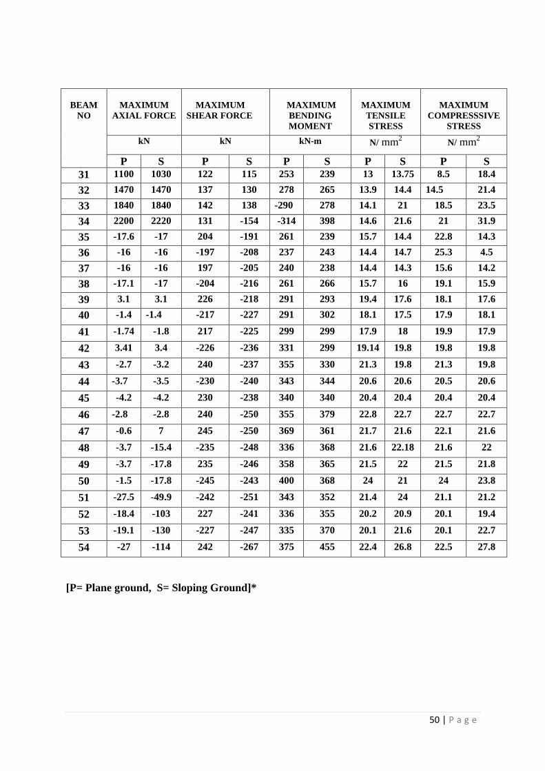
BEAM
NO
MAXIMUM
AXIAL FORCE
MAXIMUM
SHEAR FORCE
MAXIMUM
BENDING
MOMENT
MAXIMUM
TENSILE
STRESS
MAXIMUM
COMPRESSSIVE
STRESS
kN kN kN-m N/ mm2 N/ mm
2
P S P S P S P S P S
31 1100 1030 122 115 253 239 13 13.75 8.5 18.4
32 1470 1470 137 130 278 265 13.9 14.4 14.5 21.4
33 1840 1840 142 138 -290 278 14.1 21 18.5 23.5
34 2200 2220 131 -154 -314 398 14.6 21.6 21 31.9
35 -17.6 -17 204 -191 261 239 15.7 14.4 22.8 14.3
36 -16 -16 -197 -208 237 243 14.4 14.7 25.3 4.5
37 -16 -16 197 -205 240 238 14.4 14.3 15.6 14.2
38 -17.1 -17 -204 -216 261 266 15.7 16 19.1 15.9
39 3.1 3.1 226 -218 291 293 19.4 17.6 18.1 17.6
40 -1.4 -1.4 -217 -227 291 302 18.1 17.5 17.9 18.1
41 -1.74 -1.8 217 -225 299 299 17.9 18 19.9 17.9
42 3.41 3.4 -226 -236 331 299 19.14 19.8 19.8 19.8
43 -2.7 -3.2 240 -237 355 330 21.3 19.8 21.3 19.8
44 -3.7 -3.5 -230 -240 343 344 20.6 20.6 20.5 20.6
45 -4.2 -4.2 230 -238 340 340 20.4 20.4 20.4 20.4
46 -2.8 -2.8 240 -250 355 379 22.8 22.7 22.7 22.7
47 -0.6 7 245 -250 369 361 21.7 21.6 22.1 21.6
48 -3.7 -15.4 -235 -248 336 368 21.6 22.18 21.6 22
49 -3.7 -17.8 235 -246 358 365 21.5 22 21.5 21.8
50 -1.5 -17.8 -245 -243 400 368 24 21 24 23.8
51 -27.5 -49.9 -242 -251 343 352 21.4 24 21.1 21.2
52 -18.4 -103 227 -241 336 355 20.2 20.9 20.1 19.4
53 -19.1 -130 -227 -247 335 370 20.1 21.6 20.1 22.7
54 -27 -114 242 -267 375 455 22.4 26.8 22.5 27.8
[P= Plane ground, S= Sloping Ground]*
51 | P a g e
52 | P a g e
53 | P a g e

54 | P a g e
55 | P a g e
56 | P a g e
57 | P a g e
58 | P a g e
59 | P a g e
60 | P a g e
61 | P a g e
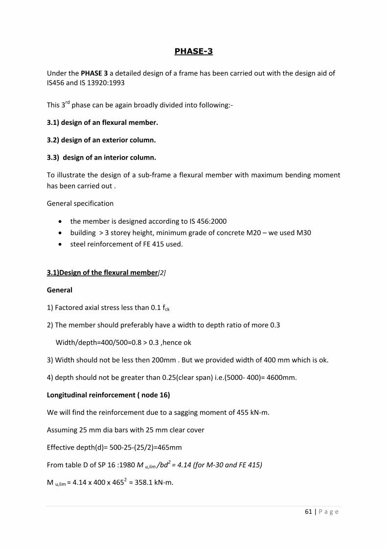
PHASE-3
Under the PHASE 3 a detailed design of a frame has been carried out with the design aid of IS456 and IS 13920:1993
This 3rd phase can be again broadly divided into following:-
3.1) design of an flexural member.
3.2) design of an exterior column.
3.3) design of an interior column.
To illustrate the design of a sub-frame a flexural member with maximum bending moment
has been carried out .
General specification
the member is designed according to IS 456:2000
building > 3 storey height, minimum grade of concrete M20 – we used M30
steel reinforcement of FE 415 used.
3.1)Design of the flexural member[2]
General
1) Factored axial stress less than 0.1 fck
2) The member should preferably have a width to depth ratio of more 0.3
Width/depth=400/500=0.8 > 0.3 ,hence ok
3) Width should not be less then 200mm . But we provided width of 400 mm which is ok.
4) depth should not be greater than 0.25(clear span) i.e.(5000- 400)= 4600mm.
Longitudinal reinforcement ( node 16)
We will find the reinforcement due to a sagging moment of 455 kN-m.
Assuming 25 mm dia bars with 25 mm clear cover
Effective depth(d)= 500-25-(25/2)=465mm
From table D of SP 16 :1980 M u,lim /bd2 = 4.14 (for M-30 and FE 415)
M u,lim = 4.14 x 400 x 4652 = 358.1 kN-m.
62 | P a g e
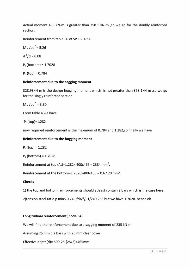
Actual moment 455 kN-m is greater than 358.1 kN-m ,so we go for the doubly reinforced
section.
Reinforcement from table 50 of SP 16: 1890
M u /bd2 = 5.26
d 1/d = 0.08
Pt (bottom) = 1.7028
Pc (top) = 0.784
Reinforcement due to the sagging moment
328.98kN-m is the design hogging moment which is not greater than 358.1kN-m ,so we go
for the singly reinforced section.
M u /bd2 = 3.80
From table 4 we have,
Pt (top)=1.282
now required reinforcement is the maximum of 0.784 and 1.282,so finally we have
Reinforcement due to the hogging moment
Pt (top) = 1.282
Pc (bottom) = 1.7028
Reinforcement at top (At)=1.282x 400x465 = 2384 mm2.
Reinforcement at the bottom=1.7028x400x465 =3167.20 mm2.
Checks
1) the top and bottom reinforcements should atleast contain 2 bars which is the case here.
2)tension steel ratio p min≤ 0.24 ( fck/fy) 1/2=0.258 but we have 1.7028. hence ok
Longitudinal reinforcement( node 34)
We will find the reinforcement due to a sagging moment of 235 kN-m.
Assuming 25 mm dia bars with 25 mm clear cover
Effective depth(d)= 500-25-(25/2)=465mm
63 | P a g e
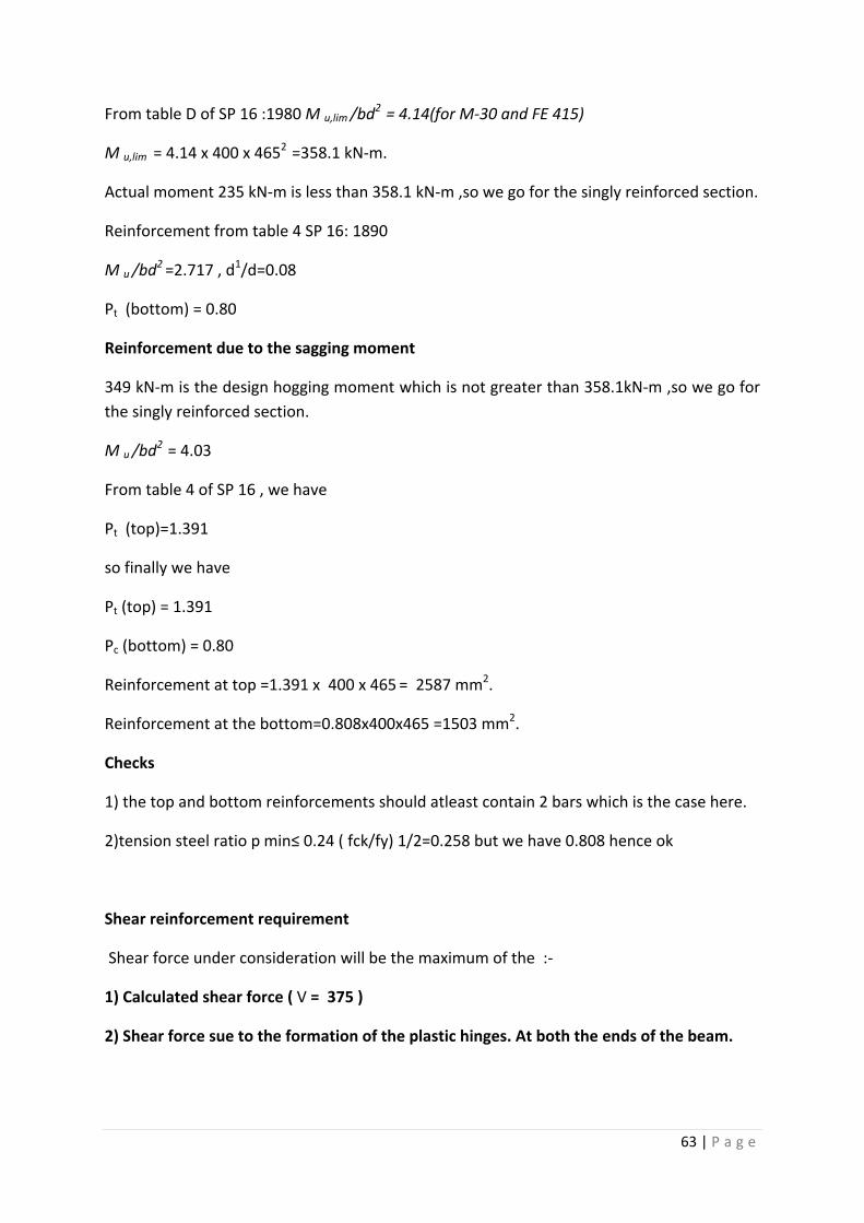
From table D of SP 16 :1980 M u,lim /bd2 = 4.14(for M-30 and FE 415)
M u,lim = 4.14 x 400 x 4652 =358.1 kN-m.
Actual moment 235 kN-m is less than 358.1 kN-m ,so we go for the singly reinforced section.
Reinforcement from table 4 SP 16: 1890
M u /bd2 =2.717 , d1/d=0.08
Pt (bottom) = 0.80
Reinforcement due to the sagging moment
349 kN-m is the design hogging moment which is not greater than 358.1kN-m ,so we go for
the singly reinforced section.
M u /bd2 = 4.03
From table 4 of SP 16 , we have
Pt (top)=1.391
so finally we have
Pt (top) = 1.391
Pc (bottom) = 0.80
Reinforcement at top =1.391 x 400 x 465 = 2587 mm2.
Reinforcement at the bottom=0.808x400x465 =1503 mm2.
Checks
1) the top and bottom reinforcements should atleast contain 2 bars which is the case here.
2)tension steel ratio p min≤ 0.24 ( fck/fy) 1/2=0.258 but we have 0.808 hence ok
Shear reinforcement requirement
Shear force under consideration will be the maximum of the :-
1) Calculated shear force ( V = 375 )
2) Shear force sue to the formation of the plastic hinges. At both the ends of the beam.
64 | P a g e
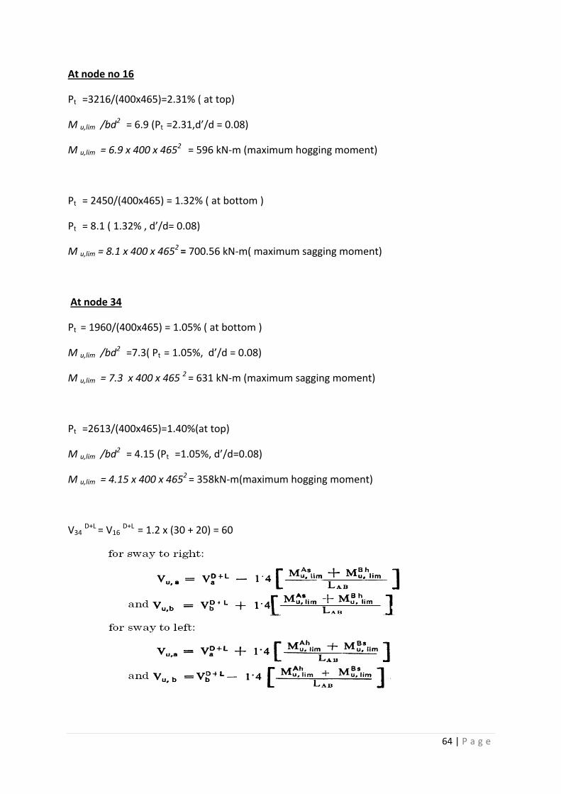
At node no 16
Pt =3216/(400x465)=2.31% ( at top)
M u,lim /bd2 = 6.9 (Pt =2.31,d’/d = 0.08)
M u,lim = 6.9 x 400 x 4652 = 596 kN-m (maximum hogging moment)
Pt = 2450/(400x465) = 1.32% ( at bottom )
Pt = 8.1 ( 1.32% , d’/d= 0.08)
M u,lim = 8.1 x 400 x 4652 = 700.56 kN-m( maximum sagging moment)
At node 34
Pt = 1960/(400x465) = 1.05% ( at bottom )
M u,lim /bd2 =7.3( Pt = 1.05%, d’/d = 0.08)
M u,lim = 7.3 x 400 x 465 2 = 631 kN-m (maximum sagging moment)
Pt =2613/(400x465)=1.40%(at top)
M u,lim /bd2 = 4.15 (Pt =1.05%, d’/d=0.08)
M u,lim = 4.15 x 400 x 4652 = 358kN-m(maximum hogging moment)
V34 D+L = V16 D+L = 1.2 x (30 + 20) = 60
65 | P a g e
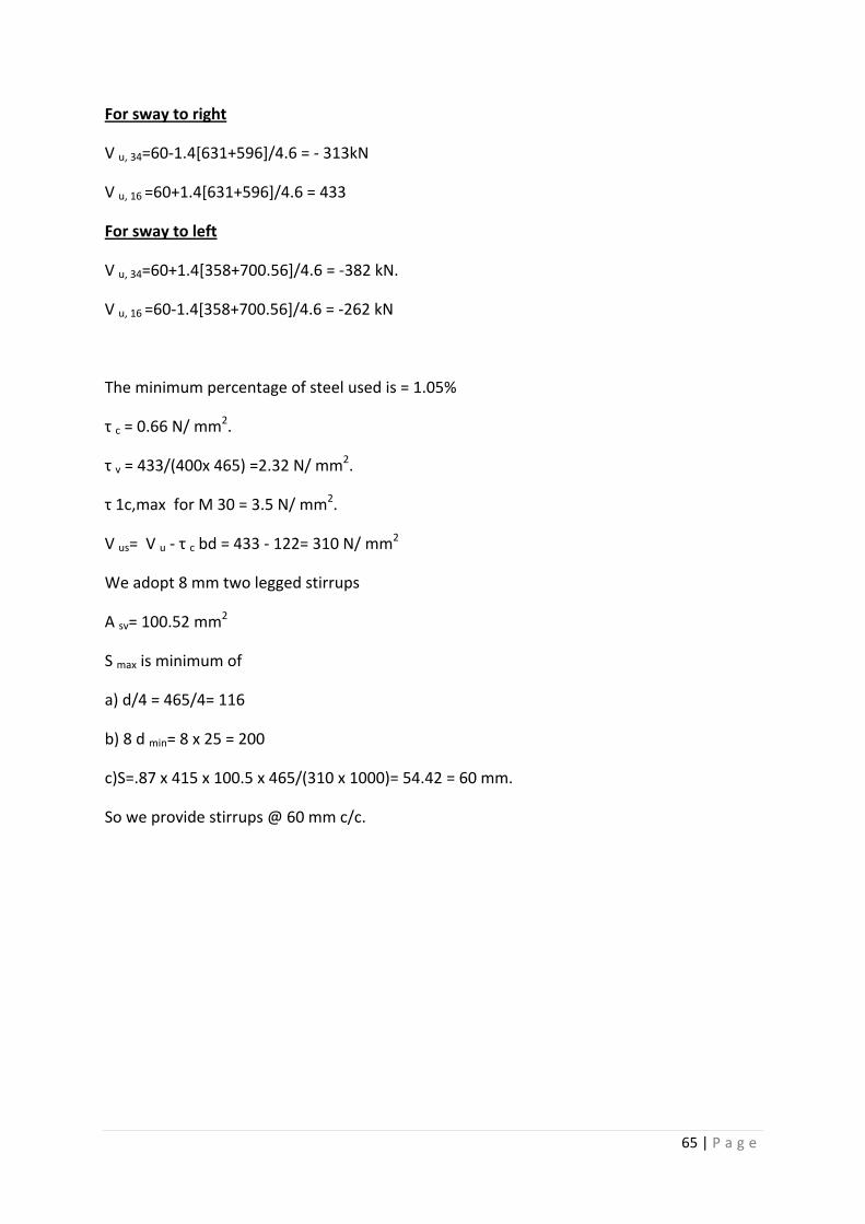
For sway to right
V u, 34=60-1.4[631+596]/4.6 = - 313kN
V u, 16 =60+1.4[631+596]/4.6 = 433
For sway to left
V u, 34=60+1.4[358+700.56]/4.6 = -382 kN.
V u, 16 =60-1.4[358+700.56]/4.6 = -262 kN
The minimum percentage of steel used is = 1.05%
τ c = 0.66 N/ mm2.
τ v = 433/(400x 465) =2.32 N/ mm2.
τ 1c,max for M 30 = 3.5 N/ mm2.
V us= V u - τ c bd = 433 - 122= 310 N/ mm2
We adopt 8 mm two legged stirrups
A sv= 100.52 mm2
S max is minimum of
a) d/4 = 465/4= 116
b) 8 d min= 8 x 25 = 200
c)S=.87 x 415 x 100.5 x 465/(310 x 1000)= 54.42 = 60 mm.
So we provide stirrups @ 60 mm c/c.
66 | P a g e
3.2)Design of exterior column[2]
In this example the columns of the ground floor are designed for illustrations. The exterior
columns no 1 is designed for the forces based on maximum interaction ration (1 in this case)
We have size of the column 400mm x 500 mm
Concrete mix M 30
Vertical reinforcement Fe 415
Axial load 1160 kN
Moment from load 229 kN
The general requirement of the column for the ductility will follow IS 13920:1993 and
vertical reinforcement of the column is designed according to IS 456:2000. The transverse
and the special confinement reinforcement will be d by following the IS 13920:1993 and IS
456:2000.
General (Column subjected to bending and axial load)
IS 13920:1993 will be applicable if the axial stress > 0.1 f 1ck.
1160 x 1000/ (400 x 500) = 5.8 > 0.1 f 1ck = 3.
Minimum dimension of the member ≥ 250 and we have taken 400 which is ok.
Shortest cross section dimension / perpendicular dimension ≥ 0.4 and we have the
same ratio as 0.8
Vertical (longitudinal) reinforcement
Assume 20 mm 𝛷 with 40 mm cover ( d1= 40 +10= 50 mm, d1 / D = 50/ 500 = 0.1)
From chart 44 SP 16: 1980 ( d1/ D = 0.1, 415 N/ mm2 )
Pu/ fckbD = 1160 x 1000 / (30 x 400 x 500)= 0.19
Mu/ fckbD2 = 0.075
Reinforcement on four sides from chart 44 SP 16: 1980
P/fck =0.045, reinforcement in % =0.045 x 30 = 1.35 %
A 1s = pbd/ 100= 1.35 x 400 x 500 / 100 = 2700mm2 ( 8 @ 22mm 𝛷 bars of area 3040 mm2 )
Some important notes:-
Lap splices only at the central half of the member
Hoops over the entire splice length at a spacing <150
67 | P a g e
Not more than 50 % of the bars are spliced at one section.
Transverse reinforcement
Some important points:-
Hoop requirement as per fig 7 in IS 13920:1993
If the length of the hoop > 300 mm a cross tie shall be provided as shown in fig
Hoop spacing should not exceed half the least lateral dimension of the column i.e.
400/2 = 200 mm
The design shear force for the column shall be the maximum of the the following:-
a) calculated shear force as per the analysis which is 53.29 kN.
b)factored shear force as given by Vu = 1.4 [ M bLu,lim + MbR
u ,lim / h st]
where M bLu,lim and MbR
u ,lim are the moments of opposite sign of beams framing in to the
column from opposite faces and hst is the storey height.
moment of resistance of the beam at node 2 ,assuming all other beams of the same floor is
designed for the same critical design conditions as that of beam 54, we have
At node 2
Pt = 1960/(400x465) = 1.05% ( at bottom )
M u,lim /bd2 =7.3( Pt = 1.05%, d’/d = 0.08)
M u,lim = 7.3 x 400 x 465 2 = 631 kN-m (maximum sagging moment)
Pt =2613/(400x465)=1.40%(at top)
M u,lim /bd2 = 4.15 (Pt =1.05%, d’/d=0.08)
M u,lim = 4.15 x 400 x 4652 = 358kN-m(maximum hogging moment)
V u = 1.4 [ 631/6]= 147.23 kN
𝛛 = 1 +3 P 1u/A 1g f 1ck = 1 + (3 x 1160 x 1000) / [(400x500-3040) x 30] = 1.5890> 1.5
So w use 𝛛 = 1.5
Now corrected τ c = 1.5 x 0.724 =1.086 N/ mm2.
Vc = τ c bd = 1.086 x 400 x 500 = 217.2 kN.
68 | P a g e
Thus nominal shear reinforcement is to be provided in accordance to IS 456.
We use 8 mm 𝛷, two legged stirrups of area 100.5 mm2.
For minimum stirrups we have
S v ≤ A sv 0.87f y / 0.4 i.e. ≤ 225
The spacing shall be lesser of the
a) 0.75 d= 0.75 x 475 = 356
b) 256 as calculated.
So we provide 8 mm phi two legged stirrups @ 225 mm. c/c
Special confining reinforcement
Special confining reinforcement is to be provided over a length of l0 towards the mid span of
the column
l0≥ *depth of the member = 500 mm+
[1/6 of the clear span which is 1 m in this case]
[450 mm]
The spacings of the hoop shall not exceed
S max < [¼( minimum member dimensions) = 100 in this case]
[ Should not be less than 75]
[ Should not be greater than 100]
Minimum area of cross section of the bar forming hoop is
Ash = 0.18 sh fck / fy ( Ag /Ak – 1)
We use s = 100 mm from above and h= 400
So we have Ash = 130 mm2.
Using 10 mm dia bar ( 78.53 mm2) at a spacing of 100 x 78.53 / 130= 60 mm i.e . @ 60 mm
c/c
69 | P a g e
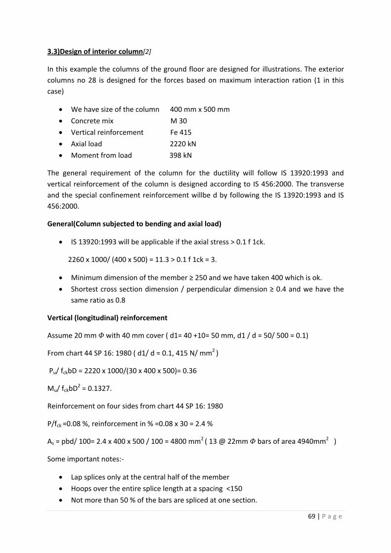
3.3)Design of interior column[2]
In this example the columns of the ground floor are designed for illustrations. The exterior
columns no 28 is designed for the forces based on maximum interaction ration (1 in this
case)
We have size of the column 400 mm x 500 mm
Concrete mix M 30
Vertical reinforcement Fe 415
Axial load 2220 kN
Moment from load 398 kN
The general requirement of the column for the ductility will follow IS 13920:1993 and
vertical reinforcement of the column is designed according to IS 456:2000. The transverse
and the special confinement reinforcement willbe d by following the IS 13920:1993 and IS
456:2000.
General(Column subjected to bending and axial load)
IS 13920:1993 will be applicable if the axial stress > 0.1 f 1ck.
2260 x 1000/ (400 x 500) = 11.3 > 0.1 f 1ck = 3.
Minimum dimension of the member ≥ 250 and we have taken 400 which is ok.
Shortest cross section dimension / perpendicular dimension ≥ 0.4 and we have the
same ratio as 0.8
Vertical (longitudinal) reinforcement
Assume 20 mm 𝛷 with 40 mm cover ( d1= 40 +10= 50 mm, d1 / d = 50/ 500 = 0.1)
From chart 44 SP 16: 1980 ( d1/ d = 0.1, 415 N/ mm2 )
Pu/ fckbD = 2220 x 1000/(30 x 400 x 500)= 0.36
Mu/ fckbD2 = 0.1327.
Reinforcement on four sides from chart 44 SP 16: 1980
P/fck =0.08 %, reinforcement in % =0.08 x 30 = 2.4 %
As = pbd/ 100= 2.4 x 400 x 500 / 100 = 4800 mm2 ( 13 @ 22mm 𝛷 bars of area 4940mm2 )
Some important notes:-
Lap splices only at the central half of the member
Hoops over the entire splice length at a spacing <150
Not more than 50 % of the bars are spliced at one section.
70 | P a g e
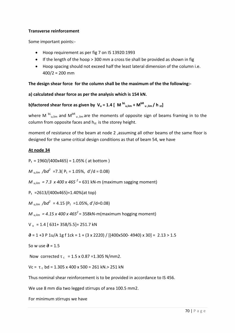
Transverse reinforcement
Some important points:-
Hoop requirement as per fig 7 on IS 13920:1993
If the length of the hoop > 300 mm a cross tie shall be provided as shown in fig
Hoop spacing should not exceed half the least lateral dimension of the column i.e.
400/2 = 200 mm
The design shear force for the column shall be the maximum of the the following:-
a) calculated shear force as per the analysis which is 154 kN.
b)factored shear force as given by Vu = 1.4 [ M bLu,lim + MbR
u ,lim / h st]
where M bLu,lim and MbR
u ,lim are the moments of opposite sign of beams framing in to the
column from opposite faces and hst is the storey height.
moment of resistance of the beam at node 2 ,assuming all other beams of the same floor is
designed for the same critical design conditions as that of beam 54, we have
At node 34
Pt = 1960/(400x465) = 1.05% ( at bottom )
M u,lim /bd2 =7.3( Pt = 1.05%, d’/d = 0.08)
M u,lim = 7.3 x 400 x 465 2 = 631 kN-m (maximum sagging moment)
Pt =2613/(400x465)=1.40%(at top)
M u,lim /bd2 = 4.15 (Pt =1.05%, d’/d=0.08)
M u,lim = 4.15 x 400 x 4652 = 358kN-m(maximum hogging moment)
V u = 1.4 [ 631+ 358/5.5]= 251.7 kN
𝛛 = 1 +3 P 1u/A 1g f 1ck = 1 + (3 x 2220) / [(400x500- 4940) x 30] = 2.13 > 1.5
So w use 𝛛 = 1.5
Now corrected τ c = 1.5 x 0.87 =1.305 N/mm2.
Vc = τ c bd = 1.305 x 400 x 500 = 261 kN.> 251 kN
Thus nominal shear reinforcement is to be provided in accordance to IS 456.
We use 8 mm dia two legged stirrups of area 100.5 mm2.
For minimum stirrups we have
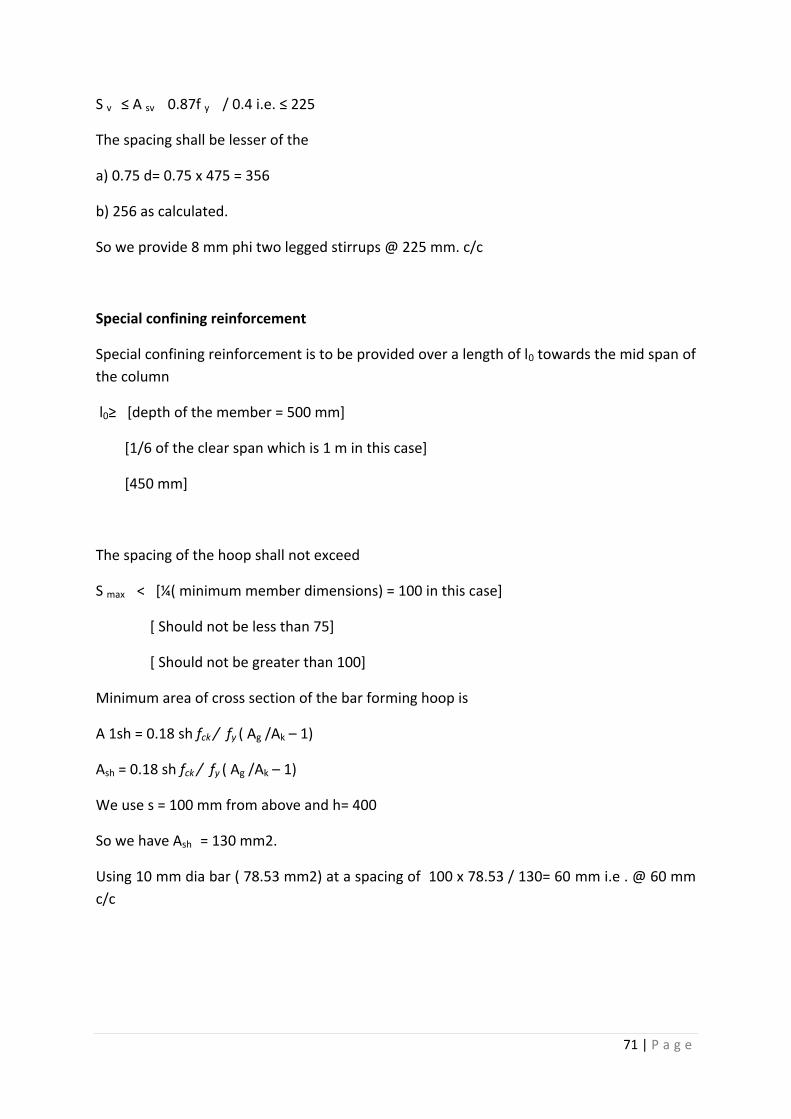
71 | P a g e
S v ≤ A sv 0.87f y / 0.4 i.e. ≤ 225
The spacing shall be lesser of the
a) 0.75 d= 0.75 x 475 = 356
b) 256 as calculated.
So we provide 8 mm phi two legged stirrups @ 225 mm. c/c
Special confining reinforcement
Special confining reinforcement is to be provided over a length of l0 towards the mid span of
the column
l0≥ *depth of the member = 500 mm+
[1/6 of the clear span which is 1 m in this case]
[450 mm]
The spacing of the hoop shall not exceed
S max < [¼( minimum member dimensions) = 100 in this case]
[ Should not be less than 75]
[ Should not be greater than 100]
Minimum area of cross section of the bar forming hoop is
A 1sh = 0.18 sh fck / fy ( Ag /Ak – 1)
Ash = 0.18 sh fck / fy ( Ag /Ak – 1)
We use s = 100 mm from above and h= 400
So we have Ash = 130 mm2.
Using 10 mm dia bar ( 78.53 mm2) at a spacing of 100 x 78.53 / 130= 60 mm i.e . @ 60 mm
c/c
72 | P a g e
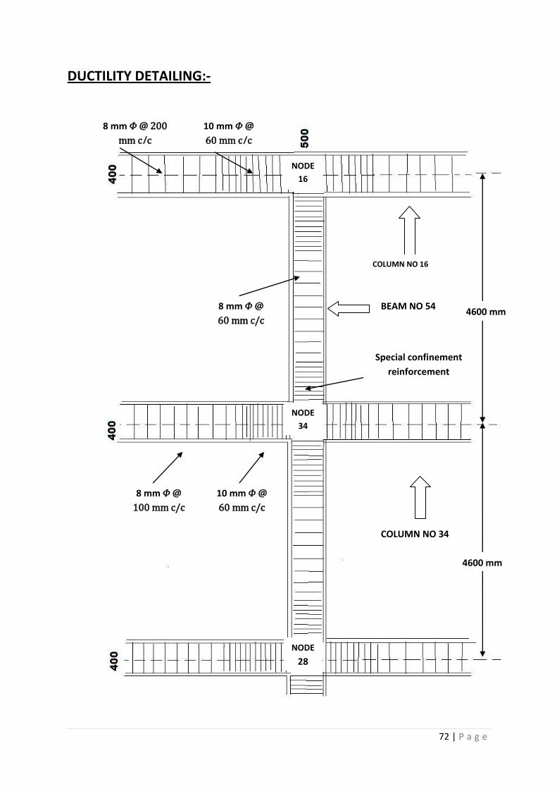
DUCTILITY DETAILING:-
NODE
16
NODE
34
NODE
28
10 mm 𝛷 @
60 mm c/c
8 mm 𝛷 @ 200
mm c/c
10 mm 𝛷 @
60 mm c/c
8 mm 𝛷 @
100 mm c/c
8 mm 𝛷 @
60 mm c/c
Special confinement
reinforcement
4600 mm
4600 mm
BEAM NO 54
COLUMN NO 16
COLUMN NO 34
73 | P a g e
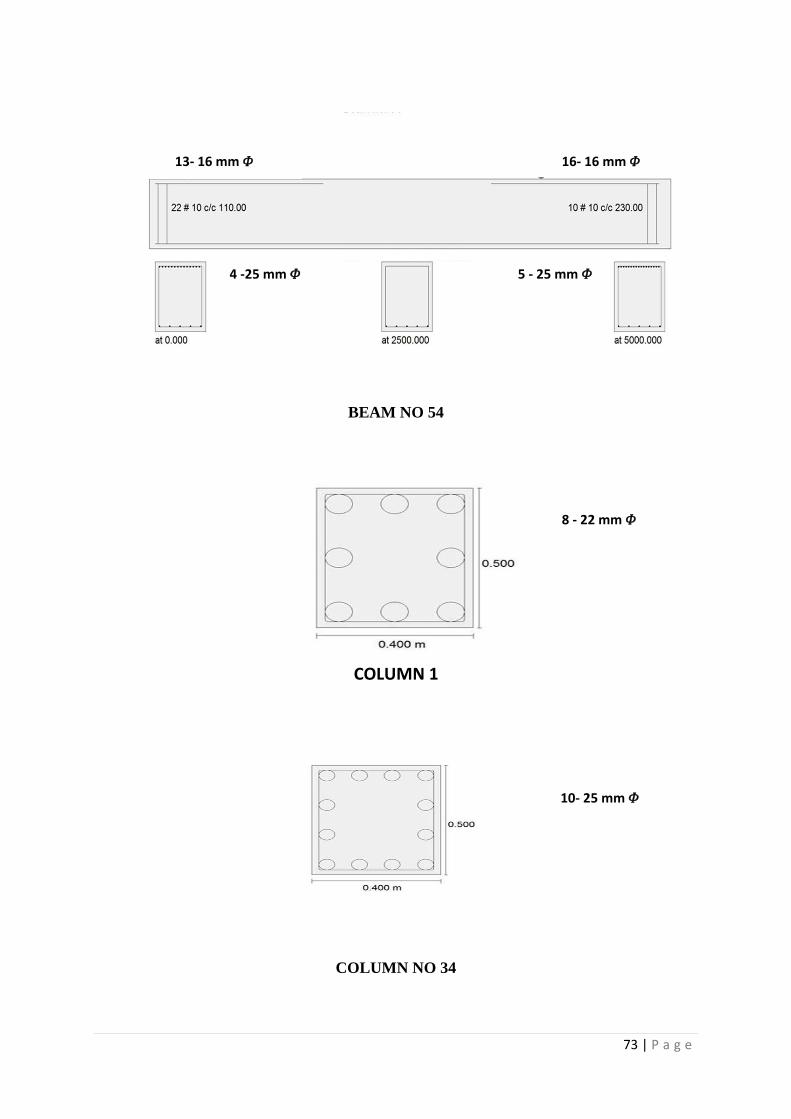
BEAM NO 54
COLUMN NO 34
13- 16 mm 𝛷 16- 16 mm 𝛷
4 -25 mm 𝛷
ITY DETAILING:-
5 - 25 mm 𝛷
8 - 22 mm 𝛷
COLUMN 1
10- 25 mm 𝛷
74 | P a g e
CONCLUSION
The tasks of providing full seismic safety for the residents inhabiting the most earthquake-
prone regions are far from being solved. However in present time we have new regulations
in place for construction that greatly contribute to earthquake disaster mitigation and are
being in applied in accordance with world practice. [8]* [4]*
In the regulations adopted for implementation in India the following factors have been
found to be critically important in the design and construction of seismic resistant buildings:
sites selection for construction that are the most favourable in terms of the
frequency of occurrence and the likely severity of ground shaking and ground failure;
high quality of construction to be provided conforming to related IS codes such as IS
1893 , IS 13920 to ensure good performance during future earthquakes.
To implement the design of building elements and joints between them in
accordance with analysis .i.e. ductility design should be done.
structural-spatial solutions should be applied that provide symmetry and regularity
in the distribution of mass and stiffness in plan and in elevation.
Whereas such the situations demands irregularity maximum effort should be given
to done away with the harmful effects like that of “ SHORT COLUMN EFFECT”
Researchers indicate that compliance with the above-mentioned requirements will
contribute significantly to disaster mitigation, regardless of the intensity of the seismic loads
and specific features of the earthquakes. These modifications in construction and design can
be introduced which as a result has increase seismic reliability of the buildings and seismic
safety for human life.
75 | P a g e
REFERENCES:-
[1].Murthy C.V.R, Learning earthquake design
[2]Agrawal, Shrikhande Mansih, earth quake resistant design of structures
[3]IS:456:2000,Plain and Reinforced code of practice.
[4]IS:1893(Part-1):2002,Criteria for earth quake resistant design of structure.
[5]IS:13920:1993,Ductile detailing of RCC structure subjected to earth quake force.
[6]SP:16,Design Aid for Reinforced concrete to IS:456:2000.
[7]Ramamurtham,Theory of structures
[8] Ashimbayev M.U., Itskov I.E., Lobodryga T.D.,living with natural and technological hazards, topic
a.2: reducing vulnerabilities in existing building and lifelines