design of carbon fibre composite driveshaft end fittings ...1044828/fulltext01.pdf · design of...
TRANSCRIPT

IN DEGREE PROJECT TECHNOLOGY,FIRST CYCLE, 15 CREDITS
, STOCKHOLM SWEDEN 2016
Design of carbon fibre composite driveshaft end fittings and adhesive joint for motorsport applications
SAMAN FANNI
FADI JWEDA
KTH ROYAL INSTITUTE OF TECHNOLOGYSCHOOL OF INDUSTRIAL ENGINEERING AND MANAGEMENT

www.kth.se

Design of carbon fibre composite
driveshaft end fittings and adhesive
joint for motorsport applications
Saman Fanni
Fadi Jweda
SA119X Examensarbete inom materialvetenskap, grundnivå
SA118X Examensarbete inom maskinteknik, grundnivå
KTH Industriell teknik och management
Hållfasthetsteknik
SE-100 44 STOCKHOLM


SA119X Examensarbete inom
materialvetenskap, grundnivå
SA118X Examensarbete inom maskinteknik,
grundnivå
Design of carbon fibre composite driveshaft end
fittings and adhesive joint for motorsport
applications
Saman Fanni
Fadi Jweda
Godkänt
2016-06-17
Examinator
Jonas Neumeister
Handledare
Artem Kulachenko
Uppdragsgivare
KTH Formula Student
Kontaktperson
Saman Fanni, Patrik
Ringdahl
Sammanfattning
En drivaxel i stål ersattes av en drivaxel i kolfiberkomposit med ståltappar fastlimmade på
varje ände för applikationer inom motorsport. En ”Single lap” och en ”Double lap”
limfogsdesign testades experimentellt i vridning. Designparametrar såsom limtjocklek,
limlängd, limbredd, limmets ändgeometri, materialstyvhet och spänningsreduktion hos
limfogen undersöktes och en förbättrad limfogsdesign föreslogs.
Testproven höll designkriteriats last men gick inte till brott även under testutrustningens
maxlast. Vidare beräkningar utfördes med antaganden baserade på ideala förhållanden och
resultat från tidigare studier. Beräkningarna visade en betydlig viktminskning följande
substitutionen av stål mot kolfiberkomposit i en drivaxel. Med ökad drivaxellängd visade
substitutionen till kolfiberkomposit även mer nödvändig i motorsportsapplikationer.


SA119X Degree Project in Materials Science and
Engineering, First Level
SA118X Degree Project in Mechanical
Engineering, First Level
Design of carbon fibre composite driveshaft end
fittings and adhesive joint for motorsport
applications
Saman Fanni
Fadi Jweda
Approved
2016-06-17
Examiner
Jonas Neumeister
Supervisor
Artem Kulachenko
Commissioner
KTH Formula Student
Contact person
Saman Fanni, Patrik
Ringdahl
Abstract
A carbon fibre composite drive shaft with steel end fittings coupled with an adhesive joint
was designed for automotive racing applications. An experimental study was conducted to test
the torque transmission strength of a single lap and a double lap joint design. Design
parameters such as adhesive thickness, lap length, lap width, adhesive fillet, adherend
tapering and adhesive stress reduction on the lap strength were investigated and an improved
design was proposed.
The adhesive test specimens showed strength surpassing the design criteria and appeared to be
beyond the limits of the testing equipment. Further calculations were made with assumptions
based on ideal conditions and results from previous studies. The calculations showed
significant weight reduction with the substitution of a conventional steel shaft with a carbon
fibre composite shaft. With increased drive shaft length, the substitution to carbon fibre
composite showed even more essential in motorsport applications.


Contents
1. Introduction ........................................................................................................................ 1
2. Literary survey ................................................................................................................... 2
2.1. Overlap stress distribution ........................................................................................... 2
2.2. Overlap geometry ........................................................................................................ 4
2.2.1. Adhesive thickness ............................................................................................... 4
2.2.2. Overlap length ...................................................................................................... 5
2.2.3. Adhesive end geometry ........................................................................................ 8
2.3. Adherend characteristics .............................................................................................. 9
2.3.1. Adherend tapering and thickness ......................................................................... 9
2.3.2. Adherend material and surface treatment ........................................................... 10
3. End fitting design & manufacture .................................................................................... 12
3.1. Dimensions ................................................................................................................ 15
3.2. Double lap .................................................................................................................. 16
3.3. Pocket lap .................................................................................................................. 17
3.4. Thin lap ...................................................................................................................... 18
3.5. FEM analysis ............................................................................................................. 18
3.6. End fitting weight ...................................................................................................... 21
4. Experimental methods ...................................................................................................... 22
4.1. Adhesive bonding ...................................................................................................... 22
4.2. Carbon fibre composite tube specifications ............................................................... 24
4.3. Testing ....................................................................................................................... 24
5. Results .............................................................................................................................. 25
6. Discussion ........................................................................................................................ 28
6.1. Evaluating the assumptions and results ..................................................................... 28
6.2. Alternative end fitting materials ................................................................................ 30
6.3. The Pocket lap and Thin lap ...................................................................................... 31
7. Conclusions ...................................................................................................................... 31
Acknowledgements .................................................................................................................. 32
References ................................................................................................................................ 32


1
1. Introduction
In motorsport, it is essential to keep the weight of the vehicle as low as possible to increase
fuel efficiency and power-to-weight ratio. It is therefore desirable to choose materials with
high specific strength and few materials in that field can compete with carbon fibre composite
materials. A high set of components in a car is made of metallic materials and can be
substituted for carbon fibre reinforced plastic (CFRP) materials. Carbon fibre composite’s
main advantages are its low density, high relative stiffness, low rotational inertia and high
vibration damping. However, carbon fibre composites are highly sensitive to machining and
need to be coupled with adhesive joints to avoid damaging the fibres. The advantage with an
adhesive joint is its characteristic to distribute the load on a larger area than bolts or rivets and
requires no holes. Despite this, an adhesive joint produces stress concentrations at its overlap
ends and needs design guidelines to minimize stresses and increase the joint strength.
Although previous studies show similar finite element (FEM) solutions and agree on several
design criteria to increase joint strength, a unified design approach is not at hand.
Adams and Peppiatt [1] made finite element studies of how partial tapering of the adherends
and an adhesive fillet affects the overlap shear stresses. They concluded that tapering and
introducing a fillet decreases the end shear stresses of the joint. Ki Soo Kim et al. [2]
experimentally tested the fatigue and static strength of a single lap joint, single lap joint with
scarf, double lap joint and double lap joint with scarf together with simulating the stresses in
these joints. Figure 1 shows four of the most common adhesive joints. They concluded that
the double lap has a much higher load-bearing capacity than the single lap, and that tapering
the composite adherend was not beneficial. Won Tae Kim and Dai Gil Lee [3] studied the
strengths of different driveshaft shapes such as a hexagonal and elliptical driveshaft and
compared them to the conventional circular form with single lap or double lap joints. They
concluded that the double lap joint had higher strength than the single lap because of a larger
bonding area and that it’s outer adherend prevented bulging of the tube from the hoop stresses.
They also concluded that the hexagonal shape had the highest strength of all single lap joints.
Figure 1 – Different types of adhesive joints

2
In this study, a conventional steel driveshaft is substituted by a carbon fibre composite
driveshaft. Steel end fittings are mounted on each end of the carbon fibre driveshaft to be
fitted into the engine and the wheel of the vehicle with tripod joints. The steel end fitting is
coupled onto the driveshaft with an adhesive joint and the tripod is mechanically mounted on
the end fitting with splines. A literary survey is conducted to determine the optimum design of
the adhesive joint. Unlike many of the previous studies regarding adhesive joints, this study
was made without any simulations for the adhesive joint because it was out of the scope of
this study. Furthermore, since motorsport applications are short-term and require lightweight
structures, fatigue and creep properties of the designs were not examined and only static
loading was considered. The carbon fibre tubes were manufactured with 40 mm inner
diameter and 2 mm wall thickness before the study was initiated. Thus, the end fittings were
the only variable for designing the adhesive joint. After designing, the steel end fittings are
manufactured and coupled onto the carbon fibre tube and experimentally tested in torsion
loading. With the experimental results, the driveshaft can be dimensioned for a specific load
and the reduction in weight from substituting a steel driveshaft with a carbon fibre driveshaft
can be found. This study is developing the driveshaft of an existing race car. The race car
produces a maximum torque of 400 Nm which occurs during engine braking. With a safety
factor of 1.5, the torque is increased to 600 Nm which is the minimum load-bearing capacity
the final designed end fittings should have.
2. Literary survey
The aim of the literary survey was to study different adhesive joint parameters that affect the
joint strength and incorporating these into an optimal design for the driveshaft end fitting. The
parameters reviewed are profoundly studied by several previous authors. Comprehensively,
these parameters can be categorized into: overlap stress distribution, overlap geometry and
adherend characteristics.
There are several different types of lap joints. Figure 1 shows the types of lap joints
mentioned in this study, including a single lap, double lap, butt joint and scarf joint.
2.1. Overlap stress distribution
The overlap stress distribution is the distribution of the shear stresses along the length of the
overlap. It was known to have peaks at the overlap ends and have been verified by multiple
analytical and experimental studies. The stress peaks and the overall stress distribution are
similar for both tension and torsion load cases. Both cases produce shear stresses in the
overlap. While shear stresses are the predominant stress type in torsion, tension loading
produces peel stresses as well. This is because tension loading of a single lap joint also creates
a bending moment on the adherends, which torsion does not. Still, the features of the stress
distribution in these two cases can be compared to each because they behave the same. Figure
2 to 4 shows the finite element mesh together with the stress distribution for both tensional
and torsional load cases taken from Adams and Peppiatt’s study [1]. Except for the stress-free

3
zone in the middle of the overlap loaded in tension, both cases have the same stress
distribution form with the torsional case having higher stress eccentricity at the ends of the lap
joint.
Figure 2 – Finite element mesh of overlap joint and adherends taken from Adams and Peppiatt’s study [1].
Figure 3 – Shear and normal stress distributions in tubular lap joints subjected to tension load. [1]
4
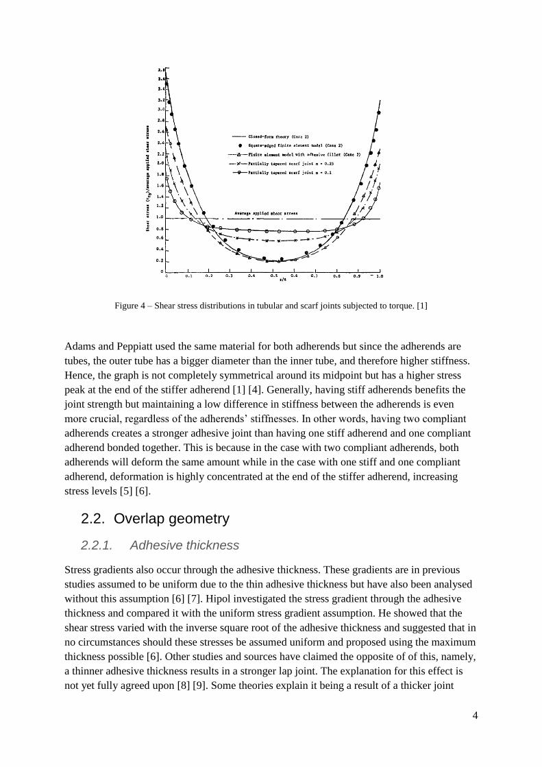
Figure 4 – Shear stress distributions in tubular and scarf joints subjected to torque. [1]
Adams and Peppiatt used the same material for both adherends but since the adherends are
tubes, the outer tube has a bigger diameter than the inner tube, and therefore higher stiffness.
Hence, the graph is not completely symmetrical around its midpoint but has a higher stress
peak at the end of the stiffer adherend [1] [4]. Generally, having stiff adherends benefits the
joint strength but maintaining a low difference in stiffness between the adherends is even
more crucial, regardless of the adherends’ stiffnesses. In other words, having two compliant
adherends creates a stronger adhesive joint than having one stiff adherend and one compliant
adherend bonded together. This is because in the case with two compliant adherends, both
adherends will deform the same amount while in the case with one stiff and one compliant
adherend, deformation is highly concentrated at the end of the stiffer adherend, increasing
stress levels [5] [6].
2.2. Overlap geometry
2.2.1. Adhesive thickness
Stress gradients also occur through the adhesive thickness. These gradients are in previous
studies assumed to be uniform due to the thin adhesive thickness but have also been analysed
without this assumption [6] [7]. Hipol investigated the stress gradient through the adhesive
thickness and compared it with the uniform stress gradient assumption. He showed that the
shear stress varied with the inverse square root of the adhesive thickness and suggested that in
no circumstances should these stresses be assumed uniform and proposed using the maximum
thickness possible [6]. Other studies and sources have claimed the opposite of of this, namely,
a thinner adhesive thickness results in a stronger lap joint. The explanation for this effect is
not yet fully agreed upon [8] [9]. Some theories explain it being a result of a thicker joint

5
having less “elastic reserve” when yielding, thus yield spreads quicker in a thicker joint.
Another theory shows that the interface stresses between the adhesive and the adherend
increases with joint thickness, and thus decreasing the joint strength [8]. However, a more
generally accepted explanation of why thinner joints are stronger than thicker joints is that
thinner ones contain less defects such as microcracks and voids [2] [9] [10]. Although, this
theory has been investigated as well and shows that defects do not increase with increased
adhesive thickness; additionally, the same investigation opposes Hipol’s conclusion and states
that stresses through the thickness increase with increased joint thickness [11].
Overall, what differentiates these latter studies and sources with Hipol’s conclusion is that
Hipol made a purely analytical analysis based on elastic conditions while the other sources are
entirely experimental. It is therefore important to rely on experimental studies rather than
analytical studies in the case of adhesive thickness. The experimental studies all proposed
joint thicknesses in close range. Soo Kim et al. tested 14 different joint thicknesses’ fatigue
life and the smallest thickness measured, 0.15 mm, sustained highest amount of cycles and
was the strongest joint [2]. It was considered that using a thinner joint than 0.15 mm would
create difficulties during bonding operations and so a 0.15 mm thick adhesive was considered
to be optimal. da Silva et al. tested 3 different thicknesses, 0.2 mm, 0.5 mm and 1 mm, under
static tension-shear loading. Their study resulted in an increase of joint strength with a
decrease of adhesive thickness, the joint strength being highest with a 0.2 mm thick joint [8].
Davies et al. studied the influence of adhesive thickness on joint strength and concluded that
the thickness should be kept below 0.8 mm in pure shear loading [11].
2.2.2. Overlap length
Increasing the width of the joint will always increase the joint strength proportionally but this
is not the case for joint length. In other words, doubling the joint width will double the joint
strength but increasing joint length may not necessarily have a positive effect [12]. Increasing
the joint length will increase the strength up to a point, the so called “effective length”, where
the strength will afterwards remain constant with increased length [13]. This phenomenon,
where an increase in joint length does not increase joint strength after a certain length, is the
consequence of the stress concentrations at the overlap ends. Increasing the overlap length
will not spread the stress concentration over a larger area but it will instead create a stress-free
zone in the middle of the overlap and the area carrying stress will be unchanged. Taken from
Hosseinzadeh and Taheri’s study [14], Figure 5 shows the stress distribution for different
overlap lengths. As shown, the stress curves remain in the same shape except for the growth
of a stress-free zone as the overlap length increases. This means that the overlap ends carry
the same stress even though the length is increased. Additionally, the outermost stress peaks
remains the same as well.
These stress peaks will remain at the same level until the overlap length reaches a minimum
length, as shown in Figure 6 taken from Hosseinzadeh et al.’s study [13].

6
Figure 5 – Comparison of stress distribution for different overlap lengths. [14]
Figure 6 - Distribution of shear stress as a function of normalized overlap length. [13]
Having an adhesive joint longer than the effective length will add unnecessary weight without
increasing strength. More so, a longer overlap can create more void content during bonding
processes and thus reducing the potential strength of the joint significantly [14]. This together
with the fact that the stress peaks are at the same level slightly before and beyond the effective
length, and that additional length adds unnecessary weight to the structure makes it beneficial
to produce an overlap with or slightly below the effective length. Figure 7 shows how the
failure load of an adhesive joint changes with increased overlap length [14]. It is evident that a
value slightly below the effective length will not weaken the adhesive joint significantly.

7
Therefore, determining the exact value of the effective length is not crucial and a qualified
design of the lap length can still be made without a FEM approach.
Figure 7 - Comparison of the ultimate torsional capacities of joints with different overlap lengths. [14]
In the studies reviewed, there are no established ways of calculating the effective length for a
given diameter or width without a finite element analysis. Three cases with given tube
diameters and corresponding effective lengths were studied as shown in Table 1.
Table 1 – Effective length of tubular adhesive joints with different diameters taken from three different studies.
Hosseinzadeh et al.
[13]
Hosseinzadeh and
Taheri [14] Hipol [6]
Adhesive diameter
[mm] 16.8 22.22 64.84
Effective length
[mm] 30 25.4 38.1
Figure 8 shows these points plotted in a graph connected with a red line and a blue line, one
for each trend, together with a black line marking the present carbon fibre tube diameter of 40
mm.
The studies all show different results for how effective length and diameter of the tube
correlate and cannot be plotted with a straight line, instead they show two different trends.
The red graph shows the effective length decreasing with increased diameter, and the blue
graph shows it increasing with increased diameter. Thus, a conclusion of how diameter and
effective length correlate is not possible to determine with the reviewed data. Although,
assuming each of these trends separately, two values of the effective length for the given
diameter of 40 mm can be extracted. If the trend plotted by the red graph is assumed, an
effective length of 10.3 mm is extracted for a 40 mm diameter. If the trend plotted by the blue

8
graph is assumed, an effective length of 30.2 mm is extracted. However, the values
connecting the red line are smaller and therefore it is likely that the deviations involved create
a larger impact on the data. Since the dots connecting the red line are closer to each other,
deviations in the values will significantly change the trend of this red line unlike the blue
trend where deviations will not have a significant impact on the slope of the blue line. In other
words, if the outermost dot on the red line decreases it’s value on the y-axis, the slope of the
red line will change significantly, whilst a change in the y-value on the outermost dot on the
blue line will not change the slope of the blue line significantly.
Conclusively, the reviewed data contains far too few data points to determine how diameter
and effective length correlate, but it is still possible to make a qualified guess of which of the
two extracted values are the most conservative. This would be the trend of the blue line giving
an effective length of 30.2 mm for the present diameter of 40 mm.
Figure 8 – Plot of data from Table 1.
2.2.3. Adhesive end geometry
During bonding operations, the end fitting and the tube are applied with adhesive and the end
fitting is pressed into the tube. Excess adhesive will automatically seep out from both ends of
the applied area and create a fillet instead of a square-edged end geometry, shown in Figure 9.
There are many shapes a fillet can adopt and when applying the end fitting to the tube, the
fillet created inside the tube is inaccessible and can not be observed or altered. The ultimate
shape depends on different variables such as the amount of adhesive applied and the method
of applying the end fitting to the tube. Since the final shape form of the fillet is unknown, it is
assumed the fillet will form a triangular shape since it is the most commonly studied shape. In
reality, the triangular fillet will sink when the adhesive cures and thus form a rounded
triangular shape shown in Figure 10.

9
Figure 9 – a) Overlap with square-edged end geometry. b) Overlap with fillet.
Figure 10 – a) Triangular fillet. b) Triangular fillet after curing.
Since the stress concentrations are at the overlap ends a fillet should modify the stress
distribution and have an effect on the load-bearing capacity of the adhesive joint. Adams and
Peppiatt [1] showed that the maximum shear stress at the ends of the overlap are reduced with
30 % with an introduction of a fillet, yet they predict stress concentrations to occur in the
adherend corner inside the fillet. It is therefore suggested by several authors that the adherend
corner that resides inside the fillet is rounded [15]. In another study, Adams and Harris [16]
experimentally compared a square-edge end geometry with a triangular fillet and a triangular
fillet with rounded adherend corners. The introduction of a fillet increased the load-bearing
capacity of the joint with 25 % compared to a square-edged joint, close to the analytically
predicted value from the previous study [1], and rounding the adherend corners increased the
load-bearing capacity with 50 % compared to the square-edged joint.
2.3. Adherend characteristics
2.3.1. Adherend tapering and thickness
Tapering is done by sloping the adherends towards their ends to increase flexibility and
reduce the stress peaks in the joint ends. Figure 11 shows a tapered single lap and a scarf joint.
A tapered joint, and in some instances called a bevelled joint, is often confused with a scarf

10
joint since the adherends in both cases are tapered. In this study only tapered joints are
designed and manufactured and since the properties of a scarf joint is not comparable to that
of a tapered joint, the literary review only considers tapered joints.
Figure 11 – Comparison between a tapered joint and a scarf joint.
Hipol [6] studied the effect of tapering the steel adherend with a 45° and a 75° angle in finite
element analysis and showed that tapering reduced stress peaks and that a 75° angle reduced
the stresses more than a 45° angle. He concluded that it is not feasible to reduce stress levels
by tapering the steel adherend since it only marginally increases joint strength and that it
would require large taper angles, which may have manufacturing constraints. In contrast, it is
believed that the constraints Hipol referred to were present at the time of the report’s release
in 1984, since large taper angles create no constraints in manufacturing today. Soo Kim et al.
[2] studied how tapering affects the joint strength both analytically and experimentally. They
used a carbon fibre composite adherend and a steel adherend, tapered both and compared their
results to the non-tapered one. The finite element results showed that the tapered overlap had
a higher load-bearing capacity than the non-tapered one but the experimental results showed
the contrary, tapering reduced the joint strength. They concluded that it was a result of
tapering the composite and that it is not beneficial to taper the fibre composite adherend.
By only tapering the steel adherend the stress peaks will decrease but simultaneously the
stiffness imbalance will be reduced. The stiffnesses of each adherend should be as close to
each other as possible and can also be calculated. However, in this study the steel adherends
are the heaviest parts of the driveshaft and should be designed as light as possible which
includes making the adherend as thin as possible regardless of stiffness imbalance. Hipol [6]
concluded that the stiffest possible composite adherend should be chosen together with the
most compliant metallic adherend to decrease stiffness imbalance. Simultaneously, in his
report a 2.54 mm thick carbon fibre tube was coupled in FEM with steel adherends with three
different thicknesses where the thinnest one, 0.635 mm, produced lowest stress levels.
Making the steel adherend even thinner will render it impossible to make a fillet with rounded
corners. Since including a fillet with rounded corners showed much greater increase in load-
bearing capacity, the inclusion of a fillet is prioritized over reducing the adherend stiffness
imbalance further.
2.3.2. Adherend material and surface treatment
The carbon fibre composite tubes were manufactured before the study and it was decided
beforehand that steel would be the material for the end fitting. It is still interesting to evaluate

11
different possible materials with respect to adhesion properties, mechanical properties,
manufacturing ease, cost and environmental effect, in search for better solutions and
lightweight designs.
Steel is in motorsport preferred to be substituted with lighter materials when possible due to
the large amount of weight steel adds to the car. Steel is on the other hand inexpensive, have
good mechanical properties, have low environmental impact and is easy to process. But if all
other variables can be sacrificed to benefit performance, lighter materials with higher specific
strength are desired. In the metallic range, aluminium, magnesium and titanium are commonly
used in motorsport. Table 2 compares steel with these metals with regards to their typical
values of density, specific strength and their highest potential values for adhesive bonding.
Table 2 – Comparison of density, specific strength and adhesive bonding strength for 4 different metals.
Density [g/cm3]
Specific strength
[kN*m/kg]
Bonding strength
[MPa], [ref.]
Steel 8 151 37, [17]
Aluminium 2.8 204 26, [17]
Titanium 4.5 288 15, [18]
Magnesium 1.7 158 20, [19]
Comparing these materials it is evident that substituting steel with any of the other three
metals is going to reduce the bonding strength and therefore a larger bonding area is needed.
As shown in section 2.2.2. (Overlap length), to increase joint strength by increasing area, the
width or the diameter should be increased and not the overlap length. Thus, the dimension of
the driveshaft is increased. This will counteract the weight reduction from using light metals
and it is therefore unclear if the substitution of steel with a lighter metal would be beneficial
in terms of weight reduction and should be studied experimentally.
The bonding operations are done by an adhesive specialist company. The surface treatment,
bonding process and curing are all done within the company and with the company
technology [20]. This is to ensure the maximum potential strength of the joint is reached.
Hence, the effect of surface treatment on the strength of the adhesive joint was not studied in
this review.
In summary, the literary study found several key points that can be integrated in the design of
an overlap joint to increase its strength. The key points include the adhesive thickness, length,
end geometry, stress reduction and lastly adherend tapering. These key points can be
incorporated together in an improved overlap design. The manual work regarding the joint
strength, such as surface treatment and bonding operations were handed over to an adhesive
specialist company.

12
3. End fitting design & manufacture
The literary study reviewed different design parameters each with potential of increasing joint
strength and an optimized design was made.
Figure 12 – Improved design of adhesive overlap joint for end fitting.
Figure 12 shows the design of the adhesive joint. The applied design parameters are noted in
Figure 12 and explained as follows:
1) Adhesive is applied on the rim of the carbon fibre tube forming a butt joint. This is to
utilize the contact area on the rim of the tube as well and not solely the overlap.
2) A “joggle” or “step” is included for the purpose of aligning the geometrical center of
the end fitting with the tube. This is manufactured with a 0.1 mm larger radius than the
inner radius of the tube to create a tight fit between the tube and the end fitting.
3) The adhesive thickness is 0.3 mm. This is to keep the thickness as low as possible and
maintain a margin of safety by having a thickness that will ensure a smooth bonding
process. Simultaneously, the adhesive specialist company advised to have a thickness
of or above 0.3 mm to prevent the cured adhesive joint from becoming too brittle.
4) The taper angle of the steel adherend, marked θ in Figure 12, is 2°. An angle of 2°
would correspond to an angle of 88° in Hipol’s study [6].
5) At the overlap end the adhesive thickness is increased to 0.6 mm to reduce strain. If
deformation is assumed constant over the overlap length, doubling the adhesive over a
small length will decrease the strain there with 50 % and therefore also the stress, as
illustrated in Figure 13. For a given deformation Δ, the shear strain α for the smaller
thickness is larger than the shear strain β for the larger thickness.
6) The rounded edge inside the fillet has a radius of 0.6 mm which is the biggest possible
radius at that edge. All other rounded edges in the adhesive joint have 0.2 mm radius.
These are not as big as possible since there could occur problems during milling if
rounded edges were too close to each other.
7) Triangular fillet.

13
Figure 13 – Illustration of strain difference for different adhesive thicknesses. a) Shear strain α for a deformation
Δ with an adhesive thickness of 0.3 mm. b) Shear strain β for a same deformation Δ with a thickness of 0.6 mm,
where α > β.
4 different end fittings were designed with a total of 3 different adhesive joints as shown in
Figure 14. The Double lap joint has the same lap joint design as the Single lap joint but
utilizes the outside area of the composite tube as well as the inside area. For the sake of clarity,
the 4 different end fittings will hereafter be called: a) Single lap, b) Double lap, c) Pocket lap,
d) Thin lap. The Single lap and the Double lap were the designs that were manufactured,
totalling to three parts including the Double lap sleeve. The pocket lap was not manufactured
with advice from the adhesive specialist company [20] on that the bonding process would be
timeconsuming. The thin lap was not manufactured mainly due to budget, material and time
restrictions, but also because the adherend failed in FEM under the the testing equipment’s
maximum torque of 1000 Nm.
All designs have two holes in the protruding end of the end fitting, marked a) and b) in Figure
15. Hole a) is made so that a steel rod can be inserted in it for the testing equipment to apply a
force couple on, which in turn induces torque on the end fitting. Hole b) is designed to let air
out from inside the tube during the bonding process. When inserting the second and last end
fitting on the tube, air is compressed into the tube where it might disturb the adhesive and
create voids, especially in the interface between the adhesive and the air which is where the
fillet is located. To eliminate this problem, hole b) lets air escape through the middle of the
end fitting. The hole is placed so it makes little impact on the strength of the structure.
The protruding end is designed differently for the study than it would be for the real
application. Since a large hole is drilled in the protruding end, it was dimensioned with a
larger diameter to not fail during testing. Therefore, the weight of the test specimens are
higher than what it would be in the real application.

14
Figure 14 – The 4 end fitting designs.
Figure 15 – Shows the two holes in the protruding end. a) Hole for a steel rod. b) Air outlet.

15
3.1. Dimensions
Table 3 shows the data for the end fitting materials. Both end fittings were made in Uddeholm
Nimax® steel except for the Double lap sleeve which was made in EN 1.4301 (SS 2333)
conventional stainless steel. This was due to the diameter of the sleeve being larger than the
diameter the Uddeholm Nimax® steel rod was available in.
Table 3 – Properties of the two steel alloys used to make the end fittings.
Density [g/cm3] Rp0.2 [MPa], [ref.] Hardness [HB]
Uddeholm Nimax® 7.9 785 360-400
EN 1.4301 (SS 2333) 7.9 340, [21] 215
The dimensions for the Single lap, the Double lap and the Double lap sleeve are shown in
Figures 16 to 18.
Figure 16 – Dimensions for the Single lap end fitting.
Figure 17 – Dimensions for the Double lap end fitting.

16
Figure 18 – Dimensions of the Double lap sleeve.
3.2. Double lap
The Single lap joint is designed according to the previously listed design parameters. The
Double lap joint is identical to that of the Single lap joint but the end fitting is designed in two
pieces due to manufacturing restraints, as shown in Figure 19. The Double lap sleeve was
made into a separate part since the available milling tools could not mill a 30 mm deep axial
pattern. Instead a V-joint was introduced between the Double lap and the sleeve where a weld
joint couples the pieces together, as shown in Figure 20. Since welding can create
deformations, the thickness around the V-joint was made thicker to minimize the
deformations the sudden difference in temperature can cause. The weld joint was TIG-welded
with the additive Elgatig 100.
Figure 19 – The Double lap consisting of two parts, it’s inner adherend and it’s sleeve.

17
Figure 20 – The two parts of the Double lap are welded together with a V-joint.
3.3. Pocket lap
The Pocket lap is designed for a different bonding process in an attempt to minimize adhesive
void content. Instead of applying adhesive onto both adherends and inserting the end fitting
into the tube, the Pocket lap is inserted into the tube and adhesive is injected through a hole
connecting to the adhesive pocket. Figure 21 shows the modified design parameters of the
Pocket lap. Adhesive is injected through a hole, a), into a pocket, b). The air located inside the
pocket is pushed out by the adhesive through a hole, c), located 180° on the opposite side of
a). Since the pocket is flat and enclosed, no previous design parameters are applied except the
thickness of the adhesive and the tapering of the adherend.
Figure 21 – The Pocket lap with it’s design parameters. a) Adhesive inlet. b) Adhesive pocket. c) Air outlet hole.

18
3.4. Thin lap
The Thin lap, shown in Figure 22, is the lightest design and is designed with two motives. If a
simple overlap without any design parameters is stronger than the adherends, it will be the
lightest possible end fitting which would be the best solution in this application. In other
words, if both the Single lap and the Thin lap are stronger than the adherends, the Thin lap
would suffice and be the best solution since it is the lightest, even if the Single lap has a
stronger joint. This is because the joint of the Single lap is too strong and the added weight of
making it stronger is therefore excessive. The reason why the Thin lap can not include any
design parameters such as a fillet is because the adherend is too thin. It is also interesting to
evaluate the differences in load-bearing capacity between the Single lap and the Thin lap to
investigate if the design parameters of the Single lap add any strength compared to an end
fitting with no design parameters. The thickness of the Thin lap adherend is chosen to be 0.5
mm to give a significant weight difference between the Thin lap and the Single lap,
thicknesses well above 0.5 mm will not make a sufficient impact on the weight.
Figure 22 – The Thin lap.
3.5. FEM analysis
All 4 designs were studied in FEM before manufacturing to assure the end fitting would not
fail during testing. The testing equipment loads a maximum of 1000 Nm in torque which was
applied in FEM. Figure 23 and 24 shows the boundary conditions. The stress behaviour of all
4 end fittings are visualized in Figure 25 to 28. The end fittings for the real application were
also analysed in FEM but with a load of 600 Nm and all designs passed.

19
Figure 23 – Application of torque on the driveshaft in FEM.
Figure 24 – Application of fixed support on the driveshaft in FEM.
Figure 25 – Single lap under a torque load of 1000 Nm in FEM.

20
Figure 26 – Double lap under a torque load of 1000 Nm in FEM.
Figure 27 – Pocket lap under a torque load of 1000 Nm in FEM.
Figure 28 – Thin lap under a torque load of 1000 Nm in FEM.

21
In the FEM analysis, neither the Single lap or the Double lap reached the proof strength of
785 MPa or 340 MPa for the Double lap sleeve. The Thin lap reached a maximum of 772
MPa on a large area on the adherend and 868 MPa at the sharp edge between the joggle and
the adherend. The Pocket lap reached 600 MPa on the outer rim and 2350 MPa in a small
singularity at the sharp edges of the air outlet hole, shown in Figure 29. This is believed to be
a boundary condition error in FEM and not a risk in reality. This is because the area where
this stress concentration is located is not bonded to the tube and should therefore not
experience high stresses, and this large stress is located at the corner which indicates that it is
a simulation error. This high-stress singularity is also the reason why the Pocket lap is so
differently colored than the other end fittings. Due to the large hole in the protruding end,
stress concentrations occur near the hole at the rounded edge, as can be seen in Figure 25 and
26.
Figure 29 – Singularity showing 2350 MPa at the air outlet hole on the Pocket lap.
3.6. End fitting weight
The difference in the protruding end of the end fitting is shown in Figure 30 where the test
specimen requires a large hole to go through the end and therefore requires a larger diameter,
increasing weight. The real application end fitting requires no such hole and can be
dimensioned smaller and weighs less. The weights of the end fitting designs, shown in Table
4, are for the real application end fittings and not the test specimens.

22
Figure 30 – The protruding ends of the test specimen end fittings (left) and the real application end fitting (right).
Table 4 – Weights of the test specimen and real application end fittings.
Single lap Double lap Pocket lap Thin lap
Weight [g] 173 295 165 133
Weight (test
specimens) [g] 235 337 - -
4. Experimental methods
4.1. Adhesive bonding
The adhesive and bonding operation process was recommended and conducted by the
adhesive specialist company [20]. The adhesive used was LOCTITE® EA 9466™ or
LOCTITE® Hysol® 9466™, a toughened high shear strength epoxy adhesive manufactured
by Henkel Corporation. Table 5 shows the properties of the adhesive. The adhesive data sheet
specifies that bonding with grit blasted steel following the ISO 4587 standard has a strength of
37 MPa and that special curing can increase the joint strength with 25 % [17]. This method
was applied in the manufacturing of the test specimens.
The end fittings were bonded on each side of a 15 cm long carbon fibre tube with inner
diameter of 40 mm and wall thickness of 2 mm. Figure 31 shows the final test specimens after
curing.
The bonding process steps were as follows:
1) Washing of the steel adherend.

23
2) Abrasion of steel adherend with Scotch-Brite brown surface conditioning disc.
3) Blowing with compressed air.
4) Application of primer 3901.
5) Abrasion of composite adherend.
6) Adhesive application process.
7) Curing.
The excess adhesive on the outside of the Double lap was manually shaped into a triangular
fillet. The Double lap is also expected to have less void content than the Single lap. This is
because the Double lap is partly filled with adhesive and then pressed onto the tube where the
adhesive will slowly be pushed up by the tube and push the air out of it’s way.
Figure 31 – The two test specimens: Single lap (top) and Double lap (bottom)

24
Table 5 – Properties of the epoxy adhesive.
4.2. Carbon fibre composite tube specifications
The composite tube has an inner diameter of 40 mm, a wall thickness of 2 mm and is made of
5 layers of carbon fibre tow. It is dimensioned for a torque of ~1000 Nm. The layers
thicknesses and fiber orientations are:
1) 0.15 mm, 90° layer
2) 0.7 mm, ±45° layer
3) 0.3 mm, 0° layer
4) 0.7 mm, ±45° layer
5) 0.15 mm, 90° layer
4.3. Testing
Torque testing was conducted at the Solid Mechanics Laboratory in KTH Royal Institute of
Science and Technology, Sweden, on an MTS 160 kN/1100 Nm torsional and axial tester at
room temperature (22 °C). The testing equipment loads a maximum of 1000 Nm in torsion.
Special steel grips were produced to hold the test specimens in place, as seen in Figure 32.
Since the torque is transferred through a small steel rod with a diameter of 12 mm it is of
importance the steel grips grip the steel rod as close to the end fitting as possible to not induce
large bending moments on the steel rod.
LOCTITE® EA 9466™
Shear strength (Grit blasted steel, ISO 4587)
37 MPa
Mix ratio by volume 2:1
Viscosity
Medium
Curing time
5 days, 22° (1 hour, 80°/100° gives 125 %
strength)

25
Figure 32 – Single lap test specimen with steel rods inserted and attached into the steel grip.
5. Results
Since a driveshaft will be loaded rapidly and abruptly during acceleration and engine braking,
the test specimens were intended to be loaded with the highest velocity the testing equipment
were capable of outputting, but for precautionary reasons they were loaded slowly to give the
opportunity of aborting the experiment if something faulted. The test specimens were
therefore initially loaded with a velocity of 0.1°/s up to 1080 Nm where they did not break or
give any indication on crack or failure. They were then loaded again with a velocity of 10°/s
where they again did not fail at the maximum load of 1080 Nm.
The aim of the experiment was to determine the strength of both adhesive joints and then with
that data dimension the end fittings load bearing capacity to 600 Nm without altering the
design parameters, to then calculate the driveshaft weight reduction. However, assumptions
must be made in order to advance with the calculations since it is only known that the test
specimens have a load-bearing capacity of more than 1080 Nm.
Notation:
D = Refers to the inner diameter of the composite tube. = 0.04 [m]
r = D/2 = Refers to the inner radius of the composite tube. = 0.02 [m]
L = Overlap length = 0.75*D = 0.03 [m]
ASL = Refers to the adhesive area on the Single lap = 0.00377 [m2]
ADL = Refers to the adhesive area on the Double lap = 0.0079 [m2]
M = Applied torque
F = Applied force = M/r
σ = Applied stress on the adhesive joint = F/A

26
Anew = Joint area for the new driveshaft dimension.
W = Weight of current steel driveshaft without tripod joints = 506 [grams]
Subscripts:
new = Refers to the new dimension of the driveshaft.
SL = Refers to the Single lap.
DL = Refers to the Double lap.
tube = Refers to the carbon fibre composite tube.
f = refers to failure.
The Double lap should produce the highest possible weight reduction since it is 2.1 wider and
therefore 2.1 times stronger than the Single lap since joint strength is proportional to joint
width. The Double lap has therefore more joint strength-per-weight than the Single lap. The
calculations were therefore focused on the weight reduction of the Double lap only.
Simultaneously, the area of the adhesive joints are calculated without void content since the
two adhesive joints are expected to contain different amount of voids and no qualified guess
can be made for each amount of void content.
Assumption 1:
Assuming the failure of the Single lap occurs at 1100 Nm, exactly above the tested and
proved value of 1080 Nm, we can dimension the Double lap design down to a new diameter
that fails at 600 Nm and then calculate the resulting weight reduction.
(1)
(2)
(3)
With a failure load of 2310 Nm for the Double lap, it results in an ideal adhesive failure stress
of 14.6 MPa. With this information, the Double lap can be dimensioned to fail at 14.6 MPa
for a failure load of 600 Nm instead.
(4)
(5)

27
(6)
extracting Dnew will give the new diameter of the driveshaft: Dnew = 2.47 [cm]
Weight reduction:
The Double lap was designed with this diameter in CAD and its weight was calculated to 120
grams. It was then analysed in FEM to assure it does not fail under a load of 600 Nm. To
calculate the new weight of the carbon fibre composite tube, the current driveshaft length of
30 cm was used together with the material density of 1.6 g/cm3. Simultaneously, reducing the
diameter of the composite tube required thicker walls to resist buckling. It was therefore
assumed that the new driveshafts with smaller dimensions required a wall thickness of 4 mm
instead of 2 mm. For this new diameter, it would give an inner diameter of 2.47 cm and an
outer diameter of 3.27 cm, resulting in a new weight of 173 grams where the steel driveshaft
weighs 506 grams. With the end fittings, this would result in a weight reduction of:
Weight reduction:
(7)
Assumption 2:
Assuming ideal conditions, the shear stress being constant over the overlap and no stress
concentrations occur at the overlap ends, the adhesive should then fail at a shear stress of 37
MPa. Assuming this would mean that the whole adhesive area distributes the stresses evenly
when in reality the middle section of the adhesive layer is less stressed than the boundary
layers.
The new dimensions can be calculated as previously:
(8)
extracting Dnew will give the new diameter of the driveshaft: Dnew = 1.77 [cm]
Weight reduction:
(9)
Assuming failure at 37 MPa, the failure load for the Double lap would equal to 5850 Nm and
2790 Nm for the Single lap.

28
Table 6 shows the weight reduction for each assumed failure load for both the Single lap and
the Double lap. The weight reductions were calculated by calculating the adhesive area
required to fail at 600 Nm of torque. Thereafter, the diameter of the shaft can be extracted by
knowing the correlation between area and tube diameter. Then this smaller end fitting is
designed in CAD and the weight is extracted through the software. The weight of the
composite tube is then calculated using the new diameter and a 4 mm wall thickness.
Table 6 – Failure load and resulting weight reduction for each assumption.
Assumed failure load for both
designs
Single lap: 1100 Nm
Double lap: 2310 Nm
Single lap: 2790 Nm
Double lap: 5850 Nm
Weight reduction 18.4 % 42.5 %
6. Discussion
6.1. Evaluating the assumptions and results
The assumptions made in the results are difficult to perceive realistically since there are no
methods of predicting the adhesive joint strength without knowing the properties of the glue
at the interface. Instead, we can compare our two assumptions with values from previous
studies where the specimens failed. Further discussion can then be made regarding the
legitimacy of the assumptions. We can compare our study with the study of Won Tae Kim &
Dai Gil Lee’s study [3] since they use similar specimens and bonding processes as in our
study, although they do not include any design parameters in their lap joints. They use a
carbon fibre composite tube with 60 mm inner diameter, 3 mm wall thickness and ±45° fibre
stacking sequence and tested a single lap and a double lap joint with steel adherends. Their
circular single lap joint had a failure load of 3200 Nm where the adhesive failed. Their
identical double lap joint had a failure load of 3626 Nm where the composite adherend failed.
Knowing their joint area and failure load, we can compare the stresses of their single lap at
failure to our two assumptions and find which of our two assumptions fit their case best. Their
overlap length was 60 mm, with an inner radius of 30 mm and an adhesive shear strength of
13.7 MPa:
(10)
(11)
Thus, at failure, Won Tae Kim & Dai Gil Lee’s [3] single lap experiences a calculated stress
of 9.4 MPa when the adhesive intrinsically experiences a shear stress of 13.7 MPa. The
calculated stress assumes the stresses being equally distributed over the area but since this is
29
not the case, the stresses being higher in the boundaries, the calculated stress at failure will be
lower than the data sheet values. Knowing that the adhesive fails when it experiences a stress
of 13.7 MPa and that the experiments showed a calculated stress of 9.4 MPa, a stress
concentration factor can be extracted by dividing the two and used in our test results to make
a better prediction of the failure load for our test specimens. The stress concentration factor
would convey how much higher the stress concentrations are above the ideal level. In their
study, the stress concentration factor is:
(12)
Dividing the shear strength of our adhesive with this factor will show at what ideal stress level
our adhesive joint would fail and this enables us to calculate the failure torque. The calculated
stress level would be:
(13)
This stress level gives a failure load of 1900 Nm for our Single lap which would result in a
weight reduction of 36 %, a failure load almost precisely between the values obtained from
assumptions 1 and 2. This value is extracted relying on values from the study of Won Tae
Kim & Dai Gil Lee’s [3]. A significant difference between the present study and theirs is that
Won Tae Kim & Dai Gil Lee did not include any design parameters for their single lap and
double lap joint design. The design parameters, as reviewed, strengthen the joint with a great
amount. Yet, these are being overlooked in our calculations since they can not be accurately
incorporated. The design parameters’ effect on joint strength can be listed to clarify the extent
of their effects that are being overlooked. Listing these would give an idea of how much
stronger our lap joints are than those of Won Tae Kim & Dai Gil Lee:
- The Butt joint: has an area of 2.64 cm2, increasing the Single lap joint area with 7 %,
therefore theoretically increasing strength with 7 %.
- Fillet with rounded adherend corners: joint strength increases with 50 % compared to a
square edged one.
- Double adhesive thickness at the overlap end: strain decreases with 50 %.
- Tapering: joint strength increases marginally.
Simultaneously, the 25 % increase in strength that the special curing of the adhesive brings
with is also overlooked. This would increase the lap shear strength from 37 MPa to 46 MPa.
Albeit, it is not proved that these listed positive effects can be summed together. In previous
experimental studies, the design parameters have been studied separately by their authors.
However, when incorporating all these design parameters at once it is not established that
their effects can be added together or that they will not interfere with each other.
Meanwhile, in both the present study and the study of Won Tae Kim & Dai Gil Lee the
Double lap is 2.1 times as wide as the Single lap and therefore 2.1 times as strong. This joint

30
strength surpassed the strength of the composite adherend in their study and it was the
composite adherend that failed for all double lap tests. This will most likely be the case as
well for the Double lap in the present study, regardless of the driveshaft diameter. When
dimensioning the driveshaft for 600 Nm, the driveshaft diameter will be decreased and so the
carbon fibre tube wall thickness must be increased to avoid buckling. Increasing wall
thickness will simultaneously increase the Double lap joint area meaning it will still be
stronger than the adherends no matter how the tube is dimensioned. This means that the
Double lap joint is probably always stronger than the adherends and the Single lap is not.
Since the weight of the driveshaft comes from the adherends, it is sought to have the
adherends as the weakest point since they can easily be dimensioned and the minimum weight
can be reached. It is therefore a matter of finding adherend materials with higher specific
strength which there are none in the case of carbon fibre.
6.2. Alternative end fitting materials
Alternatively, to further reduce weight, the materials listed in Table 2 can be used instead of
the steel. Aluminium is cheap, 3 times lighter than steel and is easily machinable. Although,
aluminium has weaker adhesive bonds compared to steel and requires a larger bonding area,
which in turn requires a larger and heavier composite tube. But the larger aluminium end
fitting may be significantly lighter than the steel end fitting and still result in a lighter
driveshaft. For example, if the driveshaft in Assumption 1 had aluminium end fittings instead
of steel end fittings, the weight reduction would be increased from 18.4 % to 49 %. This
applies to all the exemplary materials in Table 2 and remains to be experimentally tested in
order to be further discussed.
When substituting a steel driveshaft with a carbon fibre composite driveshaft, the length of the
steel driveshaft will not be fully substituted with carbon fibre composite since a length on
each end will be comprised by the end fittings. Since a carbon fibre composite driveshaft
consists of two components, a shaft and two end fittings, it is desired that the carbon fibre
tube make up as much percentage of the whole driveshaft length as possible. This is so that
the high specific strength and thus weight reduction the carbon fibre composite material
brings with can be utilized as effectively as possible. It is proven that even for a short
driveshaft of 30 cm, it is possible to reduce the weight by substituting a steel driveshaft with a
carbon fibre composite one. It is therefore essential to replace a 30 cm long driveshaft for a
carbon fibre composite driveshaft in motorsport applications and even more important when
the driveshaft is longer than this since the weight would be reduced further. With a steel
driveshaft much longer than 30 cm, a substitution to carbon fibre material can increase the
performance of a race vehicle significantly.

31
6.3. The Pocket lap and Thin lap
Two end fitting designs were discarded before manufacturing, the Pocket lap and the Thin lap.
These designs serve different purposes. The Pocket lap is designed for a different bonding
operation to minimize the void content in the adhesive joint since the void percentage equally
reduces joint strength by minimizing area and inducing cracks. However, the pocket makes it
impossible to include a fillet in the design. Simultaneously, making the joint thickness thicker
in the overlap end in the Pocket lap can create machining difficulties which can be overcome
by adding material to the adherend, increasing weight significantly. Two design parameters
that greatly increase the joint strength, namely the fillet and the increase in thickness, are
sacrificed in the Pocket lap design in an attempt to reduce void content. If the Pocket lap joint
should be comparative to the Single lap joint, the increase in bonding area and strength that
the void reduction leads to should be equal to the strength increase the fillet and the increase
in thickness at the overlap end lead to. This is unlikely since these two design parameters are
expected to greatly increase joint strength, where only the fillet increases strength with up to
50 % [16]. It is interesting to experimentally compare the torque failure strength of the Pocket
lap and the Single lap but it is also necessary to verify the effect on void content the Pocket
lap has. This can be performed by bonding the Single lap and the Pocket lap on clear
transparent tubes, enabling the researcher to directly see the voids through the tube assuming
no voids are enclosed in the adhesive thickness since the adhesive thickness is thin.
Furthermore, tapering the inside of the adherend on the Pocket lap to increase the adhesive
thickness towards the end can have the same effect as doubling the adhesive thickness on a
short length like in the Single lap design.
The second discarded design, the Thin lap, served another purpose. The Thin lap is the
lightest design where the adherend thickness is made as small as possible with no design
parameters included. This means that the Thin lap is expected to be weaker than the Single lap.
But if the Thin lap can be made stronger than the adherends, thus making the adherends the
weakest point in the driveshaft and not the adhesive joint, it is unnecessary to include design
parameters since they only add weight. The strength of the Thin lap can easily and reliably be
predicted using FEM, unlike an overlap including a lot of design parameters, and doesn’t
necessitate an experimental study. Simulating the strength of the Thin lap in FEM should give
a reliable prediction of its strength and convey whether the sacrifice of the design parameters
for lower end fitting weight is worthwhile. Furthermore, the Thin lap can be made as a double
lap joint as well.
7. Conclusions
A conventional steel driveshaft was substituted by a carbon fibre composite driveshaft with
steel end fittings for motorsport applications. A single lap and a double lap joint were
designed and manufactured with several joint design parameters aimed to increase the load-
bearing capacity of the adhesive joints and reduce the driveshaft weight. The adherends
composed of a carbon fibre composite shaft and steel end fittings bonded together with a

32
toughened epoxy adhesive. The torque bearing capacity of the joints were experimentally
tested in torsion where both test specimens showed strength surpassing the design criteria and
the maximum load capacity of the testing equipment. Further calculations were based on two
different assumptions and their reliability were later discussed. From the results and
discussion, the following conclusions were made:
- Substituting a 30 cm long conventional steel driveshaft with a driveshaft including a
carbon fibre composite shaft and steel end fittings can reduce the weight of the
driveshaft.
- With a conventional steel driveshaft longer than 30 cm, the substitution to a carbon
fibre composite driveshaft increases the weight reduction further and can greatly
increase the performance of motorsport vehicles.
- The possibility of reducing the end fitting weight by substituting the steel material
with lightweight metals such as aluminium, titanium and magnesium has potential of
further reducing the driveshaft weight. It is therefore interesting to study and should be
tested experimentally.
- The Pocket lap sacrifices some design parameters when introducing the adhesive
pocket and should therefore be designed further to minimize the negative effect these
sacrifices have on the joint strength. Furthermore, the Pocket lap should be
experimentally tested and visually studied and compared to the Single lap joint to
verify if the different bonding operation increases the joint strength. Finite element
simulation can predict the joint strength of the Thin lap and testing it experimentally is
unnecessary.
Acknowledgements
The authors wishes to acknowledge Stefan Grönqvist at Aros Polymerteknik AB, Västerås for
his contribution to this study by performing the bonding operations of the test specimens
quickly, professionally and free of charge. To Patrik Ringdahl at KTH Formula Student for
his technical expertise and for introducing us to the thesis. Our supervisor Artem Kulachenko
for his all-round general help and supervision regarding the study and presentation. Anton
Kviberg at the IIP workshop at KTH for welding the Double lap joint, and Kavithasan
Patkunam at KTH Formula Student for rendering final images of the carbon fibre driveshaft.
References
[1] R. D. Adams and N. A. Peppiatt. “Stress Analysis of Adhesively Bonded Tubular Lap
Joints”. Jan. 1977. Journal of Adhesion 9: 1, 1 — 18. DOI: 10.1080/00218467708075095
[2] Ki Soo Kim et al. “Optimal tubular adhesive-bonded lap joint of the carbon fiber epoxy
composite shaft”. 1992. Composite Structures 21 (1992) 163-176.
33
[3] Won Tae Kim & Dai Gil Lee. “Torque transmission capabilities of adhesively bonded
tubular lap joints for composite drive shafts”. 1995. Composite Structures 30 (1995) 229-240.
[4] Aixi Zhou and Jack Lesko. “Polymers and Adhesives for the Infrastructure”. Sep. 2006.
Showcase on Virginia FRP Composites: Materials, Design, and Construction. VirginiaTech.
Bristol, Virginia.
[5] L. J. Hart-Smith. “Adhesive-bonded Single Lap Joints”. Jan. 1973. Langley Research
Center Hampton, Virginia.
[6] Philip J. Hipol. “Analysis and Optimization of a Tubular Lap Joint Subjected to Torsion”.
March 1984. Department of Theoretical and Applied Mechanics, University of Illinois.
Urbana, Illinois.
[7] Erol Sancaktar & Prasad Nirantar. “Increasing strength of single lap joints of metal
adherends by taper minimization”. 2003. Journal of Adhesion Science and Technology, 17:5,
655-675. DOI: 10.1163/156856103321340796
[8] Lucas F. M. da Silva et al. “Effect of Adhesive Type and Thickness on the Lap Shear
Strength”. The Journal of Adhesion, 82:11, 1091-1115. 2006. DOI:
10.1080/00218460600948511
[9] Jonas Neumeister. (2016, May 19). RE: En fråga om lim [E-mail]. Available e-mail:
[email protected]. Message: “Tunnare skikt, tjocklek t = möjliga defekters storlek blir mindre
= sprickors storlek begränsas as skikttjockleken = maximalt KI ~sqrt(t)”.
[10] R. D. Adams and N. A. Peppiatt. “Stress analysis of adhesive-bonded lap joints”. The
Journal of Strain Analysis for Engineering Design, 9: 185-196. July 1974.
[11] P. Davies et al. “Influence of adhesive bond line thickness on joint strength”. Journal of
Adhesion and Adhesives, Vol. 29-7: 724–736. Oct. 2009.
DOI:10.1016/j.ijadhadh.2009.03.002
[12] Design and Testing of Bonded and Bolted Joints. National Physical Laboratory,
Teddington, Middlesex. 2007.
[13] Ramin Hosseinzadeh et al. “A simple approach for characterizing the performance of
metallic tubular adhesively-bonded joints under torsion loading”. Journal of Adhesion Science
and Technology, 21-16:1613-1631. 2007. DOI: 10.1163/156856107782793203
[14] Ramin Hosseinzadeh and Farid Taheri. “Non-linear investigation of overlap length effect
on torsional capacity of tubular adhesively bonded joints”. Composite Structures, Vol. 91-2:
186–195. Nov. 2009. Department of Civil and Resource Engineering, Dalhousie University,
Halifax, Nova Scotia. DOI:10.1016/j.compstruct.2009.04.047

34
[15] Lucas Filipe Martins da Silva and Andreas Öchsner. Modeling of Adhesively Bonded
Joints. Berlin-Heidelberg, Germany, Springer. 2008.
[16] R.D. Adams and J.A. Harris. “The influence of local geometry on the strength of
adhesive joints”. Journal of Adhesion and Adhesives, Vol.7-2, April 1987.
[17] LOCTITE® EA 9466™, Technical Data Sheet for LOCTITE® EA 9466™ or
LOCTITE® Hysol® 9466™. Sep. 2014.
[18] Hercules Jorge Almilhatti et al. “Adhesive bonding of resin composite to various
titanium surfaces using different metal conditioners and a surface modification system”.
Journal of Applied Oral Science, 21-6: 590–596. Nov-Dec 2013. DOI: 10.1590/1679-
775720130255
[19] Liming Liu, Welding and Joining of Magnesium Alloys. Woodhead Publishing, 2010. pp.
154-155.
[20] Stefan Grönqvist. Aros Polymerteknik AB, Saltängsvägen 11, 721 32 Västerås, Sweden.
[21] Employee at Precisionstål AB, Sorterargatan 31, 162 50 Stockholm. Private
communication. 29-04-2016.