design of cable systems for cable suspended bridges
TRANSCRIPT

Design of Cable Systems for Cable Suspended Bridgesby
Jean-Pierre Michel ChacarB.Eng. Civil Engineering
American University of Beirut(2000)
Submitted to the Department of Civil and Environmental EngineeringIn Partial Fulfillment of the Requirements for the
Degree of
Master of Engineering in Civil and Environmental EngineeringAt the
Massachusetts Institute of TechnologyJune 2001
© Jean-Pierre Michel ChacarAll right reserved
The author hereby grants to MIT permission to reproduce and to distribute publicly paperand electronic copies of this thesis document in whole and in parts
Signature of AuthorDepartm ent of Civil and Environmental Engineering
May 22, 2001
"I
Certified b
Professor of Civil And
/Jerome J. Connor
Environmental EngineeringThesis Supervisor
I'r
Chairman, Committee forMASSACHUSETTS INSTITUTE
OF TECHNOLOGY
JUN 0 4 2001
LIBRARIES
Oral BuyukozturkGraduate Students
ER
Accepted by /Z

Design of Cable Systems for Cable Suspended BridgesBy
Jean-Pierre Michel ChacarSubmitted to the Department of Civil and Environmental Engineering
On May 21,2001 in partial fulfillment of the requirements for theDegree of Master of Engineering in High Performance Structures
Abstract
Structural design requires a full understanding and knowledge of all the components
comprising the structure. The main element of a cable suspended bridge is the cablesystem. Special attention on aspects other than mathematical calculations should begiven. This thesis examines issues other than design calculation in cable systems such asprotection of cables, fatigue and wind considerations and finally, monitoring andmaintenance.
Thesis Supervisor:Title:
Professor Jerome J. ConnorProfessor of Civil and Environmental Engineering

To my Father

Acknowledgements
My utmost respect and gratitude to my father Michel who gave me the
opportunity to advance in my studies. Without his support, all this would not have been
possible.
Also, my deepest respect and gratitude goes to my mother Hilda. Her moral
support and continuous preoccupation gave me strength to persevere and go to the end.
Finally, I would like to mention my sister Sandra and brother Paul. Thank you
guys for you preoccupation and concern.
In what follows, I would like to express my thanks to all who helped me in
different ways during my thesis preparation and my academic year at MIT.
First and Foremost, my deepest gratitude to my advisor Professor Jerome J.
Connor who guided me during my stay at MIT and whose responsive feedback helped me
in meeting deadlines.
Special thanks to Lisa Grebner for being so responsive and helpful in our M.eng.
project and in my personal thesis.
Special thanks to Cynthia Stewart for helping me out with all the official issues.
Finally, a special thanks to my friends -Bass, Chris, Karim, Konstantinos, Todd-
and other fellows M.Eng. students -Noelle, Yasmin, Nick, Bart- naming just a few, but
all the other remain on my mind.
For those whose names are present above and those who have not been
mentioned, thanks you for your moral support and your strong believes in my
capabilities.
To you all - Thanks!!!
4

Table of Content
1 Introduction......................................................................................................................8
2 Cables............................................................................................................................. 10
2.1 Historical overview ............................................................................................... 10
2.2 D ifferent kinds of cables ..................................................................................... 12
2.3 Arrangem ent of cables in suspension bridges ...................................................... 15
2.3.1 Flat rectangular disposition .......................................................................... 16
2.3.2 A gglom eration of cables .............................................................................. 17
3 Protection of Cables ................................................................................................... 19
3.1 Physical dam age................................................................................................... 19
3.2 Corrosion................................................................................................................. 19
3.2.1 Grouting ....................................................................................................... 20
3.2.2 Coating ............................................................................................................. 20
3.2.3 G alvanizing ................................................................................................... 21
3.2.4 M ain cable protection in suspended bridges ................................................. 21
3.3 Fretting .................................................................................................................... 21
4 W ind Consideration ................................................................................................... 23
4.1 General characteristics ........................................................................................ 23
4.2 Rain-wind oscillation .......................................................................................... 24
4.3 W ind tunnel testing ............................................................................................ 24
5 Fatigue of Cables............................................................................................................25
6 A ctive Control................................................................................................................ 27
6.1 Neuro-Control of Cable Vibration Using ER/MR Dampers............................... 28
6.2 Active tendon control.......................................................................................... 29
7 Cable Inspection............................................................................................................. 30
7.1 Observation ............................................................................................................. 30
7.2 Electrom agnetic inspection ................................................................................. 31
7.2.1 The Eddie Current M ethod........................................................................... 3 1
7.2.2 The M agnetic Flux Leakage (M FL)............................................................. 31
7.3 A coustic surveillance or m onitoring ................................................................... 32
5

7.4 Ultrasonic testing method ....................................................................................... 34
7.5 Vibration dynamic method ...................................................................................... 34
7.6 Radiography ............................................................................................................ 35
8 Conclusion ...................................................................................................................... 36
Reference ........................................................................................................................... 37
6

Table of Figures
Fig.1 Structural Strand ................................................................................................... 12
Fig.2 Different types of structural ropes ....................................................................... 13
Fig.3 Parallel-bar cable ..................................................................................................... 13
Fig.4 Locked-coil cable................................................................................................. 14
Fig.5 Parallel w ire cable................................................................................................. 14
Fig.6 Parallel strand cable ............................................................................................ 15
Fig.7 Mockup of the Golden Gate bridge main cable ................................................... 16
Fig. 8 Flat rectangular disposition of cables ................................................................ 17
Fig.9 Rectangular arrangement of cables...................................................................... 18
Fig. 10 Hexagonal arrangement of cables...................................................................... 18
Fig. 11 Shock absorbers ..................................................................................................... 23
F ig . 12 C lam p .................................................................................................................... 2 3
Fig. 13 Stress range versus N (for parallel wire and parallel strand)............................ 26
Fig. 14 Cables implementation of ER/EM dampers .......................................................... 29
Fig.15 Active tendon control installed in the anchorage............................................... 29
Fig. 16 Magnetic Flux Leakage principal ..................................................................... 32
Fig. 17 A one-second recording showing a wire fracture and background noise ......... 33
List of Tables
Table L.a Span of Suspension bridges..........................................................8
Table 1.b Span of Cable Stayed bridges...........................................................8
Table 2 Evolution of cable strength............................................................11
7

1 Introduction
The principle of carrying a load by suspending it to a rope or cable has been utilized since
ancient times. But it was not until 1823 that the first permanent cable supported bridge
was built in Geneva. Even though the span of the structures erected at the time was of
modest dimensions, it was the start of a big impressive leap in bridge design.
Cable suspended bridges are innovative structures that are both old and new in concept.
They are old in the sense that they have been evolving over a period of 400 years and
new in a way that these structures started to attract attention in the middle of the 20th
century.
When engineers started experimenting with the use of cables in bridges, they met little
success due to the fact that the statics were not fully understood and that unsuitable
materials were used [4]. Designing started on a trial and error basis and evolved slowly.
Nowadays, in our technical age with a well-developed infrastructure, computer
communication, heavy equipment readily available and a better understanding of the
behavior of such structures, cable supported bridges are becoming much more common.
Existing cable supported bridges provide useful data regarding design, fabrication
erection and maintenance of new systems. As bridges are being built, experience on the
subject is being gained, and longer spans are being reached.
Tables L.a and 1.b show the increase in the span of cable supported bridges (suspension
bridges and cable-stayed bridges) over the years [5].
Table L.a Span (m) of Suspension bridges Table 1.b Span (m) of Cable-Stayedbridges
8
Year Name Span Country1903 Williamsburg 488 USA1924 Bear Mountain 497 USA1926 Benjamin Franklin 533 USA1929 Ambassador 564 USA1931 Georges Washington 1067 USA1937 Golden Gate 1280 USA1964 Verrazano Narrows 1298 USA1981 Humber 1410 England1998 Storebaelt East 1624 Denmark1998 Akashi Kaikyo 1990 Japan
Year Name Span Country1969 Knie 320 Germany1970 Duisburg-N. 350 Germany1975 St.Nazaire 404 France1983 Barrios de Luna 440 Spain1986 Alex Fraser 465 Canada1991 Igushi 490 Japan1991 Kvarnsund 530 Norway1993 Yangpu 602 China1995 Normandie 856 France1999 Tatara 890 Japan

The key element for both Suspension bridge and a Cable-Stayed bridge is the cable. The
evolution of these bridge types of was based on the development of cable theory and
manufacturing.
This thesis will examine the main issues regarding cables. Starting with a general
overview, this thesis discusses the main corrosion types and protection techniques used in
common practice. Some special design considerations are presented (such as wind
consideration and fatigue). Finally, cable inspection techniques and the state of the art use
of Active Control are discussed.
9

2 Cables
Cables are the fundamental elements in cable-supported structures. For that reason,
choosing among the different existing types requires special consideration.
Cables are usually made of high tensile strength steel wires having a diameter ranging
from 3 to7mm.
The general characteristics of the steel used [5]:
" Yield strength: 1180 MPA
" Tensile strength: 1570 MPA
" Strain at breaking: 4%
" Modulus of elasticity: 205 GPA
" Chemical composition: 0.8% C, 0.2% Si, 0.6% Mn, 0.05% Cu, 0.05% Ni, 0.05%
Cr, 0.03% P, 0.02% S.
This steel has a much higher yield stress and tensile strength than normal steel used in
construction (about five times and four times higher values respectively), but a much
lower ductility. Due to its high carbon content, this steel cannot be welded.
2.1 Historical overview
The cables used in cable-supported structures have the same composition of the cables
used in prestressed concrete. There is similarity not only in the material properties, but
also in the physical aspect (different kinds of cables will be presented later on).
Both types of cables have to sustain very high tension; in the prestressed concrete, the
tension is used to keep the concrete always in compression, whereas in cable-supported
structures, the high tension result from the load transmitted from the structure it to the
supporting elements).
The idea of prestressing main elements in a structure is very old. The Egyptians used to
"prestress" the hull of their ships by cooling hot metal strips attached to it.
Prestressing concrete became known and applied due to the work of Eugene Freysinnet
(French engineer 1879-1962) who is considered the "inventor of prestressing".
The research done by this remarkable engineer, led to a better understanding of the
properties and behavior of the cables to be used.
10
Even though the work of Eugene Freysinnet was done on the cables in reinforced
concrete, the cables used in cable-supported structures are very similar and behave in a
same manner, and, therefore, the principles he developed can be applied to these
structures as well.
The main difference between the two types of cables is in the ductility or the strain at
breaking. In prestressed concrete, a high ductility is required to overcome creep whereas
in cable-supported structure, an extremely low ductility is a must to ensure minimal
displacement of the structure that may be caused by cable elongation.
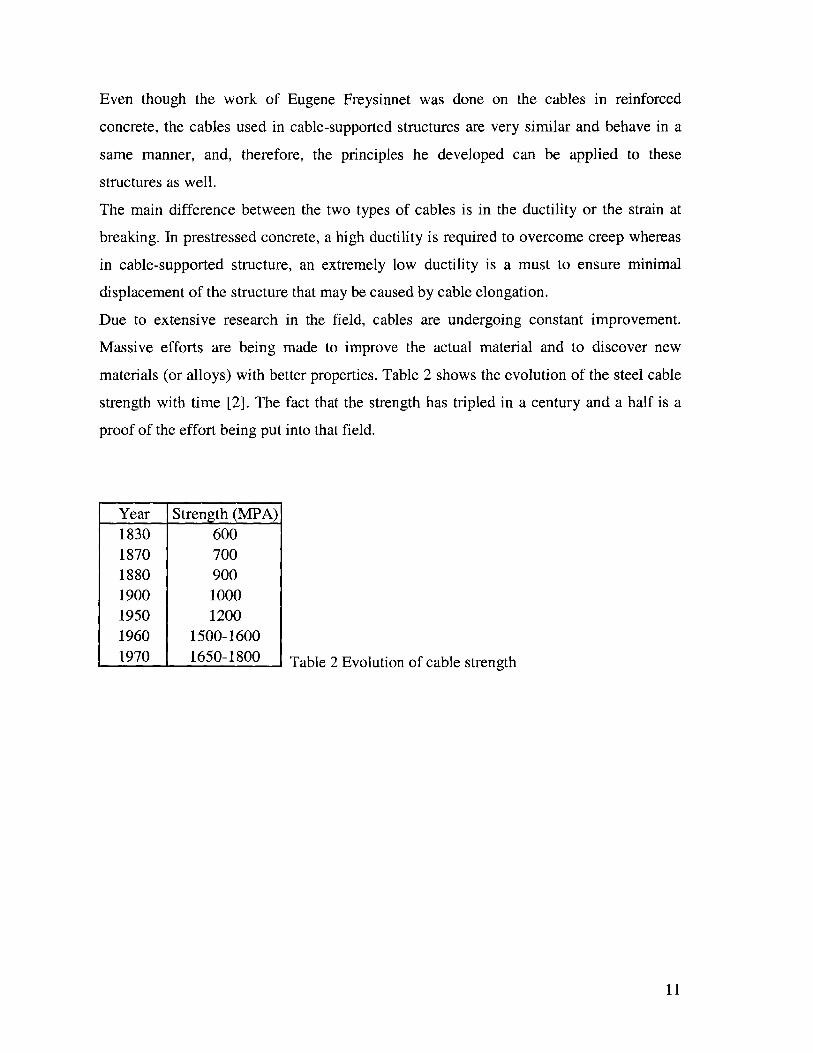
Due to extensive research in the field, cables are undergoing constant improvement.
Massive efforts are being made to improve the actual material and to discover new
materials (or alloys) with better properties. Table 2 shows the evolution of the steel cable
strength with time [2]. The fact that the strength has tripled in a century and a half is a
proof of the effort being put into that field.
Table 2 Evolution of cable strength
11
Year Strength (MPA)1830 6001870 7001880 9001900 10001950 12001960 1500-16001970 1650-1800

2.2 Different kinds of cables
Different kinds of cables are manufactured and used. Each type has its advantages and it
disadvantage and, most important of all, its unique area of applicability. It is up to the
design engineer to choose the type and specification of the cable to be used on a
particular project. The most common types of cables found in the market are:
" Parallel-bar cables
" Locked-coil strand cables:
" Parallel-wire cables
" Stranded cables
A cable may be composed of one or more structural ropes or structural strands. A strand
(with the exception of parallel wire strands) is an assembly of wires formed helically
around a center wire in one or more symmetrical layers (see fig.1) [9]. A rope is
composed of a plurality of strands helically laid round a core (see fig.2).
The main differences between a strand and a rope are:
" At equal sizes, a strand has a greater braking strength than a rope
* The modulus elasticity of a strand is higher than that of a rope
" A strand has less curvature capabilities than a rope
For the reasons stated above, strands are usually preferred to ropes in cable suspended
bridges.
Lttr t
Fig. 1 Structural Strand
12

00"
Fig.2 Different types of structural ropes
In what follows, a brief description of each type of cables is presented.
Parallel-bar cables
Parallel-bar cables are formed of steel rods or bars, parallel to each other in metal ducts,
kept in position by polyethylene spacers (fig.3)[5,6]. Since the maximum manufactured
bars length is 12m, threaded couplers are used to achieve longer spans. The rods or bars
can slide in the longitudinal direction allowing individual tensioning. Once tensioned,
grout (usually cement grout) is used to fill the large void ratio in the metal duct.
Parallel bar cables are composed usually of 7 to 10 round steel bars of diameter ranging
from 16 to 36mm.
....... .G...t
... e.. ... ... .p.
CoGrout
\ -teipe
Bar #1 Bar #2
Fig.3 Parallel-bar cable
13
.I ft
ftt.
ft 1g. *

Locked-coil strand cables
Locked-coil strand cables (fig.4) are helical shape strands composed of two types of
twisted wires [5]. The inner layers are made of round wires twisted (helicoidally) over a
straight core. The outer layers are arranged the same way using helicoidally Z- or S-
shaped wires.
The main advantages of locked-coil cables:
* Locked-coil cables have a higher resistance to corrosion due to the tight external
arrangement of the wires
" Higher modulus of elasticity
Fig.4 Locked-coil cable
Parallel wire cables
The cable is made of several parallel wires (of the same diameter) arranged in a
hexagonal shape (see fig.5).
Fig.5 Parallel wire cable
14
now - - -

The main advantage of parallel wire cables relies in the fact that the reduction in strength
and stiffness due to the twisting of the wires is eliminated. The small void ratio helps in
preventing corrosion.
The number of wires in one cable ranges from 19 to 499 7mm wires.
Parallel wire cables are usually placed in ducts but left un-grouted.
Stranded cables or Parallel-Strand cables
Stranded cables are a variation of Parallel wire cables. The only difference is that the
7mm wires are replaced with wire prestressing strands (usually 7-wires are used. See
fig.6) [2,4].
Fig.6 Parallel strand cable
2.3 Arrangement of cables in suspension bridges
Typically, a large steel cross section area (in the main cables of suspension bridges) is
required. However, very few bridges use only one large cable placed to carry the entire
load. An example of a massive bridge having one main cable on each side is the Golden
Gate Bridge. The main cable consists of 27,572 wires each of diameter 5mm (fig.7) [5].
15

Fig.7 Mockup of the Golden Gate bridge main cable
This method of having one big cross-section carrying the entire load is being replaced by
an arrangement of cables (of smaller diameter). Having an arrangement of cables, visual
inspection becomes easier since the big cable cross section is divided into smaller cables.
The disadvantage of implementing this method resides in the complexity of the
anchorage. When multiple cables are used instead of one, two main dispositions are
dominant: a flat rectangular disposition or an agglomeration of cables in a rectangular or
hexagonal disposition [2].
2.3.1 Flat rectan2ular disposition
Cables are put parallel to each other in one layer (fig. 8). They are kept usually spaced
from each other to facilitate inspection, to allow water to pass through and to facilitate
repainting (with anti corrosion paint). Replacing one cable (if it fails or need to be
replaced) can be easily done without having to close the bridge. The number of cables in
this disposition is usually limited to 8 cables.
16

~~~~~1
Fig. 8 Flat rectangular disposition of cables
2.3.2 Agglomeration of cables
Rectangular arrangement
As the required number of cables increases, the only solution is to have them in a
tighter arrangement. This disposition of cables is still a rectangular one, but multiple
layers are allowed (Fig. 9). Having this arrangement, the gap between the cables is
tremendously reduced.
Disadvantages of the rectangular arrangement:
" Inspection and maintenance are made difficult because of the tight arrangement of
cables
" Replacement of one of the cables is impossible without having to close the bridge
and interrupt the traffic
17
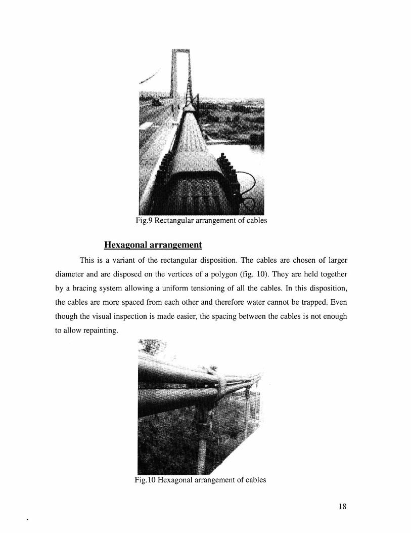
Fig.9 Rectangular arrangement of cables
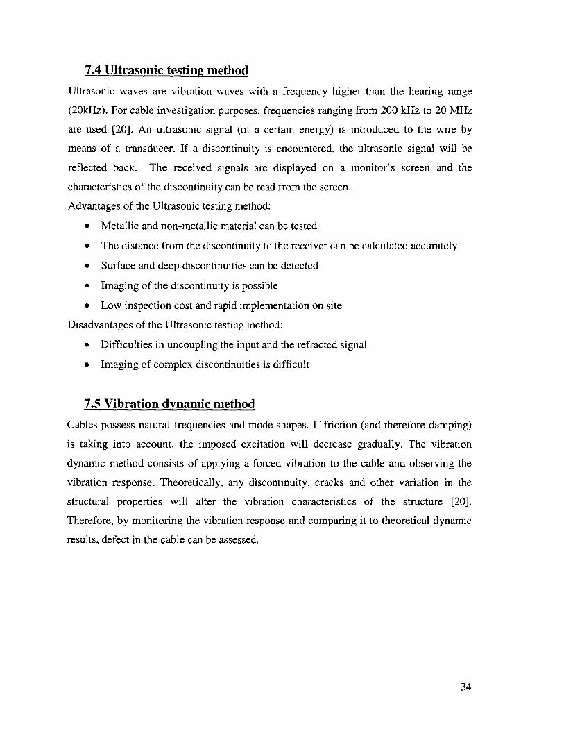
Hexagonal arrangement
This is a variant of the rectangular disposition. The cables are chosen of larger
diameter and are disposed on the vertices of a polygon (fig. 10). They are held together
by a bracing system allowing a uniform tensioning of all the cables. In this disposition,
the cables are more spaced from each other and therefore water cannot be trapped. Even
though the visual inspection is made easier, the spacing between the cables is not enough
to allow repainting.
Fig. 10 Hexagonal arrangement of cables
18

3 Protection of Cables
Cables elements are the most important component in cable supported structures and
therefore must be safely protected from external factors (such as vehicles impact, weather
and corrosion...) to ensure the safety of the structure.
The factors that affect cable integrity are the external physical damage, corrosion and
fretting. Special precaution and prevention should be taken to protect the cable structure
against each of these factors.
3.1 Physical damage
Physical damage is the damage of a cable due to an external impact. Cable should be
protected against different kinds of physical damage such as vehicle impact, fire, or even
vandalism.
The measures taken to prevent against physical damage are covering of the lower part of
the cable with a steel tube to a length of about 2m and strengthening the lower anchors to
be able to sustain a car impact or even vandalism act.
Since physical damage has a high occurrence rate, it is important that the protective
covering be designed in a way to facilitate its repair or even its replacement without
closing the bridge or interrupting even momentarily the traffic.
3.2 Corrosion
Corrosion can be defined as the deterioration of a material by reaction to its environment.
Electrochemical corrosion is the most important and common type of corrosion.
This particular type of corrosion is qualified as 'aqueous' since it involves
electrochemical phenomenon (transfer of electric charges between the cable and the
environment). This transfer is made between two parts of the cables (each one will be the
equivalent of one terminal of an electrochemical battery). Dissolution of the metal (and
therefore corrosion) we will observe at the location where electrons are liberated
(anode)[2].
The larger the number of wires of smaller diameter that are used, the more vulnerable the
cables become to surface corrosion.
19

To eliminate any risk of electromechanical corrosion, the cable should theoretically be
isolated from the surrounding. Isolation can be carried out by grouting, coating or even
galvanizing the cable. A perfect (or unbroken) isolator on the surface of the metal will
prevent the electrolyte from connecting the cathode and anode; current cannot flow; and
therefore, no corrosion can occur.
The cables nature does not ensure water proofing; if left as is, water will seep in the
cables, accumulate and will facilitate corrosion.
With good isolation techniques preventing free entry of the water, we can still have water
intrusion by capillary action, or condensation.
If water does not directly initiate the corrosion process, the moisture in the air is enough
to start corrosive action [18].
To prevent electromechanical corrosion, the different cable protection techniques will be
discussed.
3.2.1 Grouting
The oldest and most common protection against corrosion is the use of grout. Cables are
fitted in ducts that will be filled with grout (therefore isolating the cables from the
external environment). The main disadvantages of this method:
* Difficulty to fill the duct uniformly with grout
" Since the ducts are holding the grout, they should well protected against corrosion
and external factors
* The heavy weight of the grout will reduce the effective tension that a cable can
provide
* Due to its low tensile strength, the stiff grout (usually cement grout), not being
able to follow the deformation of the cables will crack. The uncovered areas of
the cable will lead to weakness points (by being exposed to the atmosphere)
3.2.2 Coating
The coating process is used mainly for the locked-coil cables. It consists of coating the
bars with anticorrosion material. These products are usually high viscosity resins, oil
20

based grease, paraffin or chemical compounds [6]. The costing is usually applied on the
surface of the cable (once installed) in form of paint.
3.2.3 Galvamzing
This method consists of immersing the wires in "a bath of melted zinc" thus providing a
25-45pm thick film around the cable prior to installation in the structure [6].
This method has proven to be extremely effective protection. Cables coated with zinc
(more than 65 years old) are still in excellent condition.
Tests have shown that grouting technique cannot be used when zinc coating is
implemented because of the chemical reactions in the grout triggered by the zinc.
3.2.4 Main cable protection in suspended bridges
The main cables in suspension bridges carry very high tension. Since any failure would
endanger the structure, special attention should be taken to prevent corrosion.
A very elaborate and protective technique has been developed to provide the main cables
in suspended bridges the highest protection possible. It consists of applying different
layers of corrosive protective material around the cable after installation.
An example of different consecutive layers used is [5]:
* A covering with polyester film
* Initial coating with acrylic resin
* A layer of non-woven glass mat pressed into place
* A second coating with acrylic resin
* A layer of woven 150mm wide glass cloth spiral wound on the cable
" A third coating with acrylic resin
" A final coating with a mixture of acrylic resin and sand to give the surface a rough
surface
3.3 Fretting
Fretting is the wearing mechanism that result from the sliding of two cables (or wires)
along each other [2]. Even if the sliding amount is very small, the repetition at the same
21

location will lead to weakening of the wires. These displacements are due to the variation
of stresses in the cable caused by either the dynamic/live load, or by the variation of
temperature. The factors that affect the degradation of the wires are the amplitude and the
speed of the slide.
To model fretting, we take two pieces of the same material and rub them longitudinally
on each other (simulating the sliding of two wires). As we keep on rubbing them, we will
notice the formation of small particles at the contact surface. Those particles (called third
bodies) are nothing else than small pieces that have detached from the surface of each
body as a result of the continuous friction. The bigger the agglomeration of the third
body, bigger the scouring effect it creates [2].
Therefore, we can say that the fretting mechanism is not directly proportional to the
number of slides but actually it is exponentially proportional.
Fretting is a natural phenomenon that cannot be avoided and that will eventually take
place. Since preventing it is not a feasible solution, the only way to deal with this
phenomenon is to try to retard it as much as possible. Galvanization offers a good
solution; not only it prevents corrosion, but also will act as a medium that will be
attacked by fretting before getting to the wire.
22

4 Wind Consideration
Aerodynamics was not a main factor influencing bridge design until 1940 with the
collapse of the "Tacoma Narrows Bridge" after only a few months of service [4]. Before
that event, only static analysis due to wind loading was considered.
The longer the span of the cable supported structure, the more slender it becomes, the
more wind becomes a critical design factor.
The wind action affects not only the bridge structure, but also the cables. These elements,
under wind load alone, can cause severe damage to the structure if not designed properly.
4.1 General characteristics
Some characteristics should be checked when the bridge or the cables are subjected to
wind loading [7]:
" The stresses felt should not be higher than the allowable values
" Displacements induced by wind (static or dynamic displacements) should not
affect serviceability
" Wind excitation should not induce cumulative fatigue on the cables.
When designing the cable for wind loading, special consideration should be taken.
The high stress level in a small cross section having no bending rigidity makes the cable a
very sensitive element to oscillation. The amplitude of the oscillations can be so high that
the serviceability of the bridge is compromised. Several methods can be adopted to solve
this problem. The most common used are viscous dampers (shock absorbers fig. 11) and
clamps with dampers between two cables (fig. 12).
Fig. 11 Shock absorbers Fig. 12 Clamp
23

4.2 Rain-wind oscillation
The wind action combined with rain seems to excite the cables even more than wind
alone. The amplitude of the excitation of cables under this condition can reach up to 14
times the cable diameter (a magnitude of 2m for a $15cm cable).
The wind excitation phenomenon is made worse by the flow of the rain water on the
surface of the cable. This flow has two main components: one that slides axially along the
cable and the other that is circumferentially around the cable. This combination of flows
along with a light wind will excite the cable tremendously.
To prevent this excitation, the smooth flow of water on the surface of the cable should be
interrupted (or disturbed). By imposing an artificial roughness on the surface, or even by
wrapping (or adding) a helical wire around the cable to channel the flow, water will no
longer flow uniformly and hence the additive effect of water to wind vibration is reduced
and sometimes eliminated.
4.3 Wind tunnel testing
To be able to fully assess the effect of wind on any bridge, engineers have adopted the
wind tunnel model analysis technique as a proof of their analytic assumptions.
A scaled model of the bridge is made. This model is the exact replication of the bridge
with all its details. Similar behavior between the model and the full-scale is achieved by
scaling the model using non-dimensional parameters [4]. The model is then put in a wind
tunnel and wind conditions (as similar as possible to on site predictions) are imposed.
The model responses are monitored, and the design is altered accordingly.
24

5 Fatigue of Cables
Fatigue is the process by which cables loose strength due to continual changes in their
state of stress over time.
In road bridges, fatigue will only govern the design of few cables. When it comes to
bridges carrying truck loading or even in railway bridges, fatigue becomes a more
dominant factor, because of the larger change in the stresses level due to larger loads [1].
Tests made at Lehigh University [1] on fatigue life, which is the number of cycle before
the first wire failed, showed that:
* The geometric properties of the cable (diameter of the strand, the size of the wire,
the grade of the cable...) have insignificant effect on fatigue life
* Fatigue limit should be expressed as a percentage of the stress range to the
breaking strength
* For a given stress range, fatigue increases with the number of wires
* Under constant cyclic loading and at 90% of the fatigue life, there is a rapid
increase of temperature.
Fatigue resistance is generally represented by Wdhler curve [5]. This curve relates the
number of repetitive loading (N) to the stress range (Aa) the cable can withstand. On a
logarithmic scale, this curve becomes linear: Log (Aa)=C1 Log (N) + C2.
Fig. 13 represents the W6hler curves for parallel wire and parallel strand cables according
to the Post Tensioning Institute (PTI) recommendations. This graph shows the allowable
stress range values that can be used without additional safety factors.
25

g 400-S300 _- Parallel
200 Wire100 Parallel
10 Strand
0 5E+0 1 E+0 2E+06 7 7
N
Fig. 13 Stress range versus N (for parallel wire and parallel strand)
The design check of the cables is based on the Wihler curve and on some formulas; the
most commonly used one is the Palmgrem-Miner formula. This formula is rather simple
to be able to assess the complexity of the fatigue problem [5]. For that reason fatigue tests
are required to consolidate the design based on fatigue stress analysis.
The tests recommended by the PTI are simple [1]. The idea behind those tests is to try to
simulate the loading and unloading of a cable until it fails.
Tests are carried on the individual strand and on a short part of a cable with the
anchorage.
For example, a cable of category B should sustain 2 millions cycles at a stress range of
158 MPA (value greater than the allowable stress range by 35 MPA). To pass the test,
less than 2% of the cable wires should break.
Fatigue is not only due to traffic. Corrosion, wind excitation or any external factor
affecting the cables also plays the role in increasing the fatigue.
Other than the direct effect on the cable, fatigue has side effects that are also detrimental.
For example the grout may crack leaving the cables exposed and therefore prone to
corrosion attack.
26

6 Active Control
One of the constant challenges in bridge engineering is to find new and better means to
design or to strengthen bridges. A revolution in design came with the introduction of
isolators and dampers that are able to dissipate the excessive energy of an earthquake
instead of letting it be stored in the system, which can cause damage. The application of
this technique to bridges (and especially to cables) offers great new opportunities and
promises. The next step after passive dampers is the application of active control
technology to the cables. Active control is even more promising since it can provide more
control authority and adaptivity to the system.
The different control mechanisms are listed below. They are used in structures and
research is being done to incorporate them in cable design.
Passive control
A control system that does not require external power source. Passive control devices
induce forces due to the motion of the structure.
Active control
System requiring external import of power to control the actuators (mechanisms that will
apply forces to the system in an prescribed manner. The added forces (generated by the
actuators) can add or dissipate energy in the system. If the signals sent to the actuators are
a response of the behavior of the structure in real time, the process is called active
feedback control.
Hybrid control
Hybrid control is a combination of active and passive control.
Semi-active control
Semi-active control is similar to the active control mechanism, but the amount of energy
supplied to the system is significantly less.
27

The application of active control have not been implemented to it full extent in cables. As
a result, little expertise and knowledge in the field is being accumulated. Research is
being developed and this subject is finding its way in becoming an important element of
cables.
6.1 Neuro-Control of Cable Vibration Using ER/MR Dampers
Electro-rheological (ER) and magneto-rheological (MR) fluids are used in semi-active
control damping devises. These kinds of dampers are designed to be used for cable
vibration control. These devices are qualified as semi-active control mechanisms since
they do not require a high intake of energy [21].
ER or MR fluids are "smart materials". They typically consist of micron-sized dielectric
polarizable or magnetically polarized particles dispersed in a carrier medium such as
mineral or silicone oil.
Under an applied electric/magnetic field, the fluid particles chains emerge to become a
semi-solid, exhibiting viscoplastic behavior and thus offering an increased resistance to
flow.
The main characteristic of these fluids is their ability to reversibly change from a free
flowing (linear viscous fluid) to a semi-solid with controllable yield strength in
milliseconds (due to the applied electric or magnetic field). The resulting damping
devices made of ER/MR fluids are controllable dampers (fig. 14) with adjustable yield
force, allowing change of properties, making the damper more adaptive to the applied
loading.
The wind/rain combination induces large amplitude vibration in stay cables as discussed
earlier. The use of ER/MR dampers will suppress the cable dynamic response
appreciably.
28

0'
Static equi-
y librium profile
0 .-.-- M R d am perX a
Fig. 14 Cables implementation of ER/EM dampers
6.2 Active tendon control
Active control is also used to control the vibration in cable stayed bridges. When the
wind velocity reaches a certain critical value: the flutter speed (due to wind gust), the
cables may exhibit excessive large amplitude vibration. Cables may fail due to excessive
large response. The traditional way to deal with this problem is to strengthen the capacity
of the cable, often leading to expensive and over-designed structures. The use of active
control as an alternative solution will control vibration more efficiently. Actuators (active
control tendons) can be installed in the anchorage of several cables (see fig.15). Sensors
and controllers are placed along the cables. Due to wind, earthquake or even traffic
loading, the cables will vibrate. The sensors detect the motion and the controllers make a
decision whether the actuators should increase or decrease the cable tension force [8,12].
Active Tendon Control
Fig. 15 Active tendon control installed in the anchorage
29

7 Cable Inspection
A survey conducted in the United States in 1991 over 590.000 bridges showed that about
35 % can be qualified as structurally deficient or even functionally obsolete [20]. This
problematic revelation is due to aging of bridges and to an increase in service load, higher
than anticipated.
To insure that existing bridges are behaving as they should and are not being subjected to
any type of corrosion, continuous inspection of bridges and cables is a must.
The most common used techniques for cable evaluation are nondestructive evaluation
techniques (NDE). These techniques allow evaluation of the size, shape, location and
orientation of any discontinuity in a cable without having a direct contact with the cable.
The different NDE techniques for cable inspection can vary widely ranging from a simple
basic visual test to more complicated and elaborated techniques such as acoustic
monitoring or even electromagnetic inspection.
7.1 Observation
Observation or visual test may be the most rudimentary technique, but it often turns out
to be one of the most efficient.
If the corrosion is at a developed stage, simple observation can localize the weak points
accurately. This is possible due to the nature of the electromechanical corrosion itself:
swelling and bulging will be observed at the location of the ionic reactions.
In the event that the corrosion is not in a very developed stage, observation is very
effective and cheap since it can localize the region of possible problem so that other more
expensive and accurate evaluation methods can be applied locally.
If the problem was a torn wire, the location can be detected by observing irregularities on
the surface of the cable.
This method is made sometime impossible because of the existence of a duct covering the
cable or a multitude of protective layers around the cables.
30

7.2 Electromagnetic inspection
This method uses the electromagnetic principles to test for any external or internal
damage such as broken wires, corrosion, cracks and wear.
7.2.1 The Eddie Current Method
The most common NDE technique that relies on the electromagnetic principle for cable
monitoring is the Eddie Current Method.
An alternative current is applied to a coil will generate a magnetic flux. Wrapping the coil
around a cable and moving it longitudinally will create an induced current in the cable.
This current will flow in an opposite direction to the current in the coil. Measuring the
magnitude of the induced current, we can know the state, the material properties and the
discontinuities in the cable [20].
Advantages of the Eddie Current Method:
" Cheap process
" Method very sensitive to small discontinuities
* No mechanical contact is necessary between the Eddie current transducer and the
cable to be tested and therefore no coating removal is required
* The entire cross section of the cable can be tested. Depth inspection can be
regulated by adjusting the frequency of the alternative current.
Disadvantages of the Eddie Current Method:
" Only electrically conductive material can be tested
" Data interpretation is complicated
" Noise in the electric current can affect the results dramatically
7.2.2 The Magnetic Flux Leakage (MFL)
The idea is to detect the damage in a cable by measuring distortions in an induced
magnetic field. The magnetized test sensor moves along the cable, letting a magnetic
field 'flow' in the cable. If the metal is intact, the whole magnetic flux will be enclosed in
the cable. In the case of a discontinuity, the magnetic flux will be distorted and a portion
31

of it will protrude to the cable outer surface. This 'leak' will be detected by an induction
coil and the nature and size of the discontinuity can therefore be known (fig. 16) [13].
Hall effect sensor(for detection of gradual efects)
Magnetic eiruit Induction Coil
/(for detection of sharp defects)
- -- - - - - - - - -
I -I t
Internal ExternalDiscontinuity Discontinuity
Fig. 16 Magnetic Flux Leakage principal
7.3 Acoustic surveillance or monitoring
Acoustic monitoring is the process of detecting acoustic waves produced when stored
elastic energy is released spontaneously as a result of the failure or movement of a
component in a structure. Acoustic Surveillance is a technique that provides long-term
monitoring of bridges by detecting failures in tensioned steel elements (wire or strand), or
by providing surveillance for damage from vehicular or ship impact [17]. The method
detects the breakage of a wire elements rather than the progressive growth of a fatigue
crack. One disadvantage is that the sensors used pick up many ambient highway noises,
but these can be filtered out so only meaningful events are reported.
When a highly stressed steel wires fractures, there is a release of energy, which is transmitted
through the cable. These acoustic events are detected by acoustic sensors (usually
accelerometers) attached to the external surface of the cable. The data from the sensors are
sent to a data collection unit by mean of coaxial cable, modem or even by wireless
telecommunication means. The cable is monitored continuously, but data is not collected,
stored and analyzed unless its magnitude is bigger than a preset value (fig.17).
32

I
i _________________
I
33
JA.
0
-----------
.. ...... ...... .. . L - H
Fig. 17 A one-second recording showing a wire fracture and background noise
Advantages of Acoustic Surveillance:
* All the system of cables can be monitored simultaneously
" The signal resulting from a sudden defect will find its path to the sensor (we do
not need to go and find the location of the discontinuity; it is going to be
calculated according to the collected data)
" Since Acoustic surveillance is an passive technique, we do not need to input
energy into the system
" The equipment needed on-site is minimal, only few sensors per cable are adequate
" The data can be continuously stored, hence generating a "history" for the defects
occurring in a cable
Disadvantage of Acoustic Surveillance:
" The need of a stimuli to locate a defect makes localization of already stabilized
crack impossible
" Some material does not allow the propagation of acoustic waves (factor that make
the use of this method irrelevant in those cases)
" Signal identification and interpretation may become difficult if the traveled path
of the wave is altered by discontinuities
* Noise and external factors can lead to false interpretation if not well filtered and
may in some case lead to false alarms
7.4 Ultrasonic testing method
Ultrasonic waves are vibration waves with a frequency higher than the hearing range
(20kHz). For cable investigation purposes, frequencies ranging from 200 kHz to 20 MHz
are used [20]. An ultrasonic signal (of a certain energy) is introduced to the wire by
means of a transducer. If a discontinuity is encountered, the ultrasonic signal will be
reflected back. The received signals are displayed on a monitor's screen and the
characteristics of the discontinuity can be read from the screen.
Advantages of the Ultrasonic testing method:
* Metallic and non-metallic material can be tested
* The distance from the discontinuity to the receiver can be calculated accurately
* Surface and deep discontinuities can be detected
* Imaging of the discontinuity is possible
* Low inspection cost and rapid implementation on site
Disadvantages of the Ultrasonic testing method:
* Difficulties in uncoupling the input and the refracted signal
" Imaging of complex discontinuities is difficult
7.5 Vibration dynamic method
Cables possess natural frequencies and mode shapes. If friction (and therefore damping)
is taking into account, the imposed excitation will decrease gradually. The vibration
dynamic method consists of applying a forced vibration to the cable and observing the
vibration response. Theoretically, any discontinuity, cracks and other variation in the
structural properties will alter the vibration characteristics of the structure [20].
Therefore, by monitoring the vibration response and comparing it to theoretical dynamic
results, defect in the cable can be assessed.
34

7.6 Radiography
Radiography has been developed in Lawrence Livermore National Laboratory (USA)
[14]. It allows the visualization of the discontinuity in cable with the use of computer
enhancement of digitized radiographs.
Monitoring cables is a new practice used to make sure that a cable have no defects
and is behaving as it should be. Other than the visual inspection, the NDE techniques
used are complex. They are the result of intensive research involving complex physics
principles. These methods are still not accurate enough and research is still being made to
improve them. The choice of a NDE technique depends on the cable material, the type of
discontinuity (as revealed by visual inspection), and finally the amount of money the
owner is willing to invest.
35

8 Conclusion
To achieve a good cable supported bridge, a full understanding of the cable behavior in
necessary. Not only the choice of cable is important but also the measures taken to
protect it. This is necessary since a failure in any of the cables could result in endangering
whole structure. This protection is a must as discussed in chapter 3 because of external
factors such as physical impact and corrosion or even by an internal mechanism such as
fretting affecting the integrity of the cable.
Special consideration during design should be taken into account since cables are very
slender elements that are affected by external conditions. These special topics discussed
in chapter 4 and 5 are the wind effect and fatigue.
Cable vibration is a common phenomenon in cables. To prevent the excessive vibration
amplitudes from affecting the integrity of the structure, damping devices are being
implemented. Chapter 6 discusses the state of the art use of Active Control in cables
through two devices: the ER/MR dampers and the Active tendon control mechanism.
Even if the cables are well protected against external factors and the design was
meticulously done, inspection is the only way to check that no unforeseen problems were
encountered during construction and that our structure is behaving as it should be. The
most common used techniques nowadays are NonDestructive Evaluation techniques; they
allow inspection without any physical contact with the cable.
Designing a cables is not only applying standard static and dynamic equations; it involves
a lot of different factors that could affect the end result as would a calculation error have.
Still a lot of research has to be done to improve cable design. The areas that still need
research and investigation are Active Control and Monitoring: Active Control to alleviate
the design by moving away from the stiffness and strength traditional design methods and
Monitoring to check for the least defect in a cable and correct it while it is still at an early
stage.
36

Reference
1- Andrzej S. Nowak, Elie Absi. Bridge Evaluation Repair and Rehabilitation. 1987.
2- J.-A. Calgaro, R. Lacroix. Maintenace et Reparation des Ponts. Presses de l'ecolenationale des Ponts et Chaussees, 1997.
3- M. Ito, Y. Fujino, T. Miyata, N. Narita. Cable Stayed Bridges Recent Developmentand their Future. Elsevier, 1991.
4- M.S. Troitsky. Cable Stayed Bridges, Theory and Design. William Clowes & Sons,1988.
5- Niels J. Gimsing. Cable Supported Bridges. John Wiley & Sons, 1997.
6- R. Walter, B. Houriet, W. Isler, P. Moia, J.J. Klein. Cable Stayed Bridges. ThomasTelford Publishing, 1999.
7- T. Miyata, N. Fujisawa, H. Yamada. Long Span Bridges and Dynamics. Springer,1999.
8- Wai-Fah Chen, Lian Duan. Bridge Engineering Handbook. CRC, 1999.
9- Walter Podolny, John B. Scalzi. Construction and Design of Cable Stayed Bridges.John Wiley & Sons, 1986
10-Alan Raine, Martin Lugg. A review of the alternating current field measurementinspection technique. 1999.http://147.46.94.112/e journals/pdf full/journal s/s05 199919305.pdf
11-Daniel Handwerker. A bridge over troubled... air currents?.http://www.jhu.edu/-newslett/04-16-98/Science/i.html
12-D. Q. Cao, J. M. Ko, Y. Q. Ni and H. J. Liu.Decentralized Active Tendon Controland Stability of Cable-Stayed Bridges.http://www.cse.polyu.edu.hk/-dynamics/ private/p-asd-cdq2.pdf
13-Electromagnetic Inspection of Suspender Cables in Suspension Bridges. 2001.http://www.cif.org/Nom2001/Nom03 01.pdf
14-Main Cables on Suspension and Cable-Stayed Bridges Corrosion Protection andInspection. 2000.http://www.vd.dk/publikationer/MainCables/Inspection.htm#top
15-Peter 0. Paulson. Practical Continuous Acoustic Monitoring of Suspension BridgeCables.
37
http://www.soundprint.com/about soundprint/technical/bridges2.pdf
16-P.O. Paulson, J.F. Elliott, D.G. Youdan. SoundPrint(r) Acoustic Monitoring toConfirm Integrity of Stressed Wire in Bridges, Structures and Water pipelines.http://www.ndt.net/article/wcndt00/papers/idn777/idn777.htm
17-Peter Paulson, David Cullington. Evaluation of Continuous Acoustic Monitoring as aMeans of Detecting Failures in Post-tensioned and Suspension Bridges. 1998.http://www.soundprint.com/about soundprint/technical/bridges6.pdf
18-Robert Nickerson. Safety Appraisal for Suspension Bridges Main Cable. 1998.http://trb.orgtrb/publications/nchrp/nchrp w20.pdf
19-Sunita K. Bhatia (b), Robert G. Hunsperger, Michael J. Chajes. Modelingelectromagnetic Properties of Bridge Cables for Non-Destructive Evaluation (a).University of Delaware.http://www.ee.udel.edu/~hunsperg/corrosionlbhatia98.pdf.
20-US Army Corps of Engineers Internet Publishing Group(. Techniques for Real-TimeDamage Assessment of Bridges. 1998.http://www.usace.army.mil/inet/usace-docs/eng-tech-ltrs/etl 1110-2-55 1/a-b.pdf
21-Y. Q. Ni, J. M. Ko, Z. G. Ying, H. J. Liu, Y. Chen. Development of Smart DampingSystems for Vibration Control of Civil Engineering Structures. 2000.http://www.cse.polyu.edu.hk/~dynamics/ private/beijingl.pdf
38