design manual 2018 plastic lined pipe and fittings · design manual 2018 plastic lined pipe and...
TRANSCRIPT
brands you trust.
Design Manual 2018
Plastic Lined Pipe and Fittings
www.cranecpe.comCrane ChemPharma & Energy
2 www.cranecpe.comCrane ChemPharma & Energy
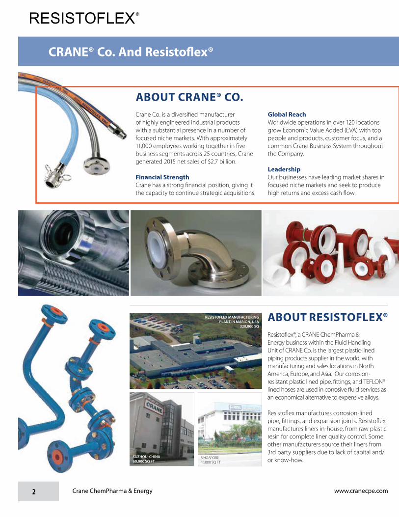
ABOUT RESISTOFLEX®Resistoflex®, a CRANE ChemPharma & Energy business within the Fluid Handling Unit of CRANE Co. is the largest plastic-lined piping products supplier in the world, with manufacturing and sales locations in North America, Europe, and Asia. Our corrosion-resistant plastic lined pipe, fittings, and TEFLON® lined hoses are used in corrosive fluid services as an economical alternative to expensive alloys.
Resistoflex manufactures corrosion-lined pipe, fittings, and expansion joints. Resistoflex manufactures liners in-house, from raw plastic resin for complete liner quality control. Some other manufacturers source their liners from 3rd party suppliers due to lack of capital and/or know-how.
ABOUT CRANE® CO.Crane Co. is a diversified manufacturer of highly engineered industrial products with a substantial presence in a number of focused niche markets. With approximately 11,000 employees working together in five business segments across 25 countries, Crane generated 2015 net sales of $2.7 billion.
Financial StrengthCrane has a strong financial position, giving it the capacity to continue strategic acquisitions.
Global ReachWorldwide operations in over 120 locations grow Economic Value Added (EVA) with top people and products, customer focus, and a common Crane Business System throughout the Company.
LeadershipOur businesses have leading market shares in focused niche markets and seek to produce high returns and excess cash flow.
RESISTOFLEX MANUFACTURING PLANT IN MARION, USA
320,000 SQ
SUZHOU, CHINA 60,000 SQ FT
SINGAPORE10,000 SQ FT
CRANE® Co. And Resisto�ex®

2 www.cranecpe.comCrane ChemPharma & Energy
ABOUT RESISTOFLEX®Resistoflex®, a CRANE ChemPharma & Energy business within the Fluid Handling Unit of CRANE Co. is the largest plastic-lined piping products supplier in the world, with manufacturing and sales locations in North America, Europe, and Asia. Our corrosion-resistant plastic lined pipe, fittings, and TEFLON® lined hoses are used in corrosive fluid services as an economical alternative to expensive alloys.
Resistoflex manufactures corrosion-lined pipe, fittings, and expansion joints. Resistoflex manufactures liners in-house, from raw plastic resin for complete liner quality control. Some other manufacturers source their liners from 3rd party suppliers due to lack of capital and/or know-how.
ABOUT CRANE® CO.Crane Co. is a diversified manufacturer of highly engineered industrial products with a substantial presence in a number of focused niche markets. With approximately 11,000 employees working together in five business segments across 25 countries, Crane generated 2015 net sales of $2.7 billion.
Financial StrengthCrane has a strong financial position, giving it the capacity to continue strategic acquisitions.
Global ReachWorldwide operations in over 120 locations grow Economic Value Added (EVA) with top people and products, customer focus, and a common Crane Business System throughout the Company.
LeadershipOur businesses have leading market shares in focused niche markets and seek to produce high returns and excess cash flow.
RESISTOFLEX MANUFACTURING PLANT IN MARION, USA
320,000 SQ
SUZHOU, CHINA 60,000 SQ FT
SINGAPORE10,000 SQ FT
CRANE® Co. And Resisto�ex®About Resistoflex......................................................................................................2Terminology and Standards ......................................................................................4Resistoflex Global Support .......................................................................................5The Thermalok and Swaging Processes ............................................................ 6 - 7Standard Material Specifications ..............................................................................8Code Compliance .....................................................................................................9Grounding - External and Internal ..........................................................................10Welded Supports ....................................................................................................11Engineering Support Services ................................................................................11Standard and Custom Coatings .............................................................................12Flange and Pipe Dimensional Data ........................................................................13Pressure Ratings and Liner Data ...........................................................................14Thermalok and Swaged Pipe Dimensions..............................................................15Minimum Flanged Spool Lengths ...........................................................................16ATL - Advanced Technology Liner ..........................................................................17Large Diameter (14" - 24") Multipiece Fitting Construction ....................................18 90 Degree Elbows and Special Angle Elbows ................................................ 19 - 2045 Degree Elbows ..................................................................................................21 Equal Tees and Reducing Tees ...................................................................... 22 - 27Crosses ............................................................................................................... 28Short Stack Tees and Crosses ...............................................................................29Instrument Tees .............................................................................................. 30 - 35Strainer Tee Assembly ............................................................................................3645 Degree Laterals .................................................................................................37Concentric and Eccentric Reducers ............................................................... 38 - 41Ductile Iron and Carbon Steel Reducing Filler Flanges.................................. 42 - 47Blind Flanges ..........................................................................................................48Spectacle Blind Flanges .........................................................................................49Spacers .......................................................................................................... 50 - 51Bull's Eye Sight Indicators ......................................................................................5290 Degree Elbows ..................................................................................................53Reducing 90 Degree Elbows ..................................................................................5445 Degree Elbows ..................................................................................................55Equal Tees and Reducing Tees ...................................................................... 56 - 58Instrument Tees .............................................................................................. 59 - 61Crosses ..................................................................................................................6245 Degree Laterals .................................................................................................63Concentric and Eccentric Reducers ............................................................... 64 - 67Reducing Filler Flanges .................................................................................. 68 - 69PTFE Nozzle Liner .................................................................................................70Thermowell Baffles .................................................................................................71Reinforced Dip Pipes and Spargers ............................................................... 72 - 73Reducing Filler Flanges for Dip Pipes ....................................................................74Solid PTFE Dip Pipes and Spargers ......................................................................75PTFE Mixing Tee Nozzles ......................................................................................76Complex Shapes Lined with PP, ETFE, and PVDF ................................................77MultiAxis® Bent Piping ............................................................................................78CONQUEST® Flangeless Piping System Design Considerations .................. 79 - 86CONQUEST® Testing and Verification Data ................................................... 87 - 92Joint Reduction Technologies - Life Cycle Cost Estimating ............................ 93 - 97Pressure Drop Data ................................................................................................98Flange Bolt Torquing and Bolt Torque Requirements ................................... 99 - 101Bolt and Stud Length Requirements.....................................................................102Bolt Torque Sequence ..........................................................................................103Pressure Testing Plastic-Lined Pipe .....................................................................104Storage and Maintenance ....................................................................................105Heat Tracing .........................................................................................................106Insulation and Venting ..........................................................................................107
Table of Contents
Introduction
PTFE-Lined Fittings
Technical Data
PP/PVDF/PFA Lined Fittings
Ancillary Products
4 Crane ChemPharma & Energy www.cranecpe.com
Terminology and StandardsTerminology & Standards
PTFE Polytetrafluoroethylene
PFA Perfluoroalkoxy
PVDF Polyvinylidene Fluoride, manufactured by Arkema under the name Kynar ® and Kynar Flex®
PP Polypropylene
ETFE Ethylenetetrafluoroethylene
ANSI American National Standards Institute
ASME American Society of Mechanical Engineers
ASTM American Society for Testing and Materials
A395 ASTM standard specification for ferritic ductile iron castings for flanges and fittings.
A403 ASTM standard specification for wrought stainless steel weld fittings
A105 ASTM standard specification for forged carbon steel used for flanges
A182 ASTM standard specification for forged stainles steel used for flanges
A106 ASTM standard specification for Standard Specification for Seamless Carbon Steel Pipe for High-Temperature Service
A587 ASTM standard specification for electric-resistance-welded low-carbon steel pipe for use as process lines in chemical industries.
A53 ASTM standard specification for carbon steel pipe.
A513 ASTM standard specification for electric-resistance-welded carbon and alloy steel mechanical tubing
A216 ASTM standard specification for carbon steel castings for fittings
A234 ASTM standard specification for wrought carbon steel weld fittings
A312 ASTM standard specification for stainless steel pipe
ASTM F1545-15a TABLE 3 STANDARD LINER COLOR
INDUSTRY ASSOCIATIONS & STANDARDS
LINER MATERIALS
PTFE White (natural color - no pigment added)
PVDF Black (available unpigmented for high-purity applications)
PP Orange (available unpigmented for high-purity applications)
PFA Natural - off white
ETFE Natural - shiny, milky white
ASTM F1545-15a
Resistoflex fully complies with ASTM F1545-15a, including qualification testing on representative pipe/fittings. This qualification testing includes high/low temperature aging, steam/cold water temperature cycling, and vacuum testing. Qualification test reports are available on request, per the requirements of ASTM F1545-15a. All finished lined piping components are electrostatically tested at 30 KV. Hydrostatic testing is available on request.
Standard Specification for Plastic-Lined Ferrous Metal Pipe, Fittings, and Flanges

5www.cranecpe.com Crane ChemPharma & Energy
Crane Resistofl ex main offi ces and manufacturing location is in Marion, NC, and we have a well-established network of distributors and ChemPharma & Energy sales offi ces throughout the world. This extensive network offers our customers local, knowledgeable, and personalized service, regardless of location. Resistofl ex customers can rely on support from authorized distributors and ChemPharma & Energy sales offi ces in the Americas, Europe, Asia, Australia, and the Middle East. Resistofl ex fabricates lined pipe and fi ttings in Fabrication Centers located in Europe, Asia, and Australia.
Our distributors are not just order takers. Many of them share over 50 years of partnership with Resistofl ex, and all are experienced in the technology of fl uid handling and how plastic lined pipe can be used to solve fl uid handling problems safely and economically. All of our distributors are dedicated to providing unmatched customer service. Additional involvement with, and experience in related products results in a team of professionals able to assist in any specialized project.
To fi nd a local distributor or ChemPharma & Energy sales offi ce, visit www.cranecpe.com or contact our Customer Service Center at (828) 724-4000.
Global Support
St. Mary's, AustraliaFabrication Center
SingaporeFabrication Center
Marion, NCHeadquarters and Manufacturing
Suzhou, ChinaFabrication Center
Waalwijk,The NetherlandsFabrication Center

6 Crane ChemPharma & Energy www.cranecpe.com 7
The Thermalok Process:
• Incoming lots of resin are analyzed in our Quality Assurance laboratory for conformance to established raw materialspecifications as required by ASTM F1545-15.
• The liner is formed under controlled conditions to a size somewhat larger than the I.D. of the steel housing intowhich it will be installed. It is then thoroughly inspected for conformance to design specifications. Next, the lineris subjected to a battery of quality tests designed to ensure liner integrity.
• The liner is then drawn through a sizing die at carefully controlled draw rates which results in a calcul ated reduction in the oustide diameter.
• A programmed heating cycle relaxes the liner inside the steel housing, resulting in a snug liner fit. Design allowances are incorporated in this procedure to eliminate undesirable stresses in the finished product.
• Both liner ends of the pipe spool are then hot flared. Temperature, time and pressure are carefully monitored.• The finished pipe is then tested in accordance with ASTM F1545-15 standards.
This unique Thermalok process provides lined pipe with dimensional stability under vacuum, pressure, and thermal cycling conditions, which prevents liner buckling and cracked flares within operational limits.
Drawing and Sizing
Thermalok Field Flare Pipe
Thermalok Field Flare (FF) pipe is Flange x Plain End or Plain End x Plain End pipe with movable liner for distributor or end- user fabrication 1 with the following features:
• Resistoflex manufactures Field Flare pipe utilizing the the same Thermalok Process as factory-finished pipe, but the process is modified to result in a movable liner.
• The liner can be removed from the pipe, allowing the fabricator a wide variety of flange options, including the Resistoflex field flare flange, all types of weld flanges, and lap joint flanges.
• Resistoflex Field Flare pipe has the same performance characteristics of the factory-finished pipe, including full vacuum capability.
• Available in PTFE, PP, and PVDF, in the same sizes as
• Resistoflex Field Flare pipe has passed all ASTM F1545-15 Qualification Testing
factory-finished spools.
• Housings are available in CS or SS.
1 - Special fabrication tooling and training required.
Resistoflex Thermalok steel pipe and liner act as a monolithic unit, even during extreme thermocycling. Combining dissimilar materials with very different coefficients of thermal expansion, our precision Thermalok Process locks the plastic liner into the pipe housing, making it full vacuum rated throught the liner’s temperature range. We developed and patented the Thermalok process for lining steel pipe in the 1950’s, and have been the world leader in the manufacture of plastic-lined piping products ever since.
The Thermalok® Process

7www.cranecpe.com Crane ChemPharma & Energy
The process of swaging, as performed on the Abbey Etna Rotary Swager, consists of hammering metal to reduce its diameter without cutting or grinding.
We start with ASTM A513 tube that has a slightly larger OD than ASME B36.10 pipe, insert the pre-molded liner into the tube, and feed both into the swager. The swager reduces the tube OD to the equivalent of ASME B36.10 pipe, while in the process fully locking the tube down on to the liner.
The result is a lined pipe that acts as a monolithic unit throughout the temperature range, and passes all ASTM F1545-15 qualification tests.
The Swaging Process

8 Crane ChemPharma & Energy www.cranecpe.com
Standard Materials Speci�cations
Liners: PTFE — Polytetrafluoroethylene, ASTM D4894 and D4895 PFA — Perfluoroalkoxy, ASTM D3307 PVDF — Polyvinylidene Fluoride, ASTM D3222 and D5575 PP — Polypropylene, ASTM D4101
Pipe: Thermalok (Carbon Steel): 1" through 4" size, Sch. 40 Carbon Steel per ASTM A53 ERW, Grade B Type E or A587 ERW 6" - 8" size, Sch. 40 Carbon Steel per ASTM A53 ERW, Grade B Type E 10" size, Sch. 30 Carbon Steel per ASTM A53 ERW, Grade B Type E 12" size, Sch. 20 Carbon Steel per ASTM A53 ERW, Grade B Type E 14" - 24" size, Standard Wall Carbon Steel per ASTM A53 ERW, Grade B Type E
Note: ASTM A106 Gr. B available on request Thermalok (Stainless Steel) 304LSS or 316LSS: 1" through 8" size, Sch. 40 Stainless Steel per ASTM A312 ERW 10" size, Sch. 30 Stainless Steel per ASTM A312 ERW 12" size, Sch. 20 Stainless Steel per ASTM A312 ERW 14" - 24", Standard Wall Stainless Steel per ASTM A312 ERW
Swaged: 1" through 4" size, Sch. 40 Carbon Steel per ASTM A513 ERW Flanges: Lap-joint, 1" - 12" size, Ductile Iron ASTM A395, dimensions per ASME B16.42 Class 150 Lap-joint, 1" - 12" size, Forged Carbon Steel, ASTM A105, dimensions per ASME B16.5 Class 150 or Class 300 Lap-joint, 1" - 12" size, Forged Stainless Steel, ASTM A182, dimensions per ASME B16.5 Class 150 or Class 300 Threaded (Swaged pipe), 1" - 4" size, Forged Steel ASTM A105, dimensions per ASME B16.5 Class 150 or Class 300
Note: Standard flange configuration for Thermalok pipe spools and most PTFE-lined fittings is rotating lap joint.
The lap is a "flared lap" conforming to ASME B31.3 Para. 306.4 Flared Laps. Fixed flanges are available.
Fittings: Fabricated Carbon Steel: Components per ASTM A587, ASTM A53 and/or ASTM A234 Fabricated Stainless Steel: Components per ASTM A312 and/or ASTM A403 Cast Fittings: Ductile Iron Casting (60-40-18) per ASTM A395 or Cast Steel per ASTM A216 Gr. WCB Fittings Flange Material: Ductile Iron Casting (60-40-18) per ASTM A395, or Cast Steel per ASTM A216 Gr. WCB, or Forged Carbon Steel per ASTM A105, or Forged Stainless Steel per ASTM A182.
Fabrication: Pipe and Fittings Tolerances: Dimension Tolerance, in. Length and Centerline Dimensions ± 1 / 8" (3.2 mm) Fixed Flange Bolt Hole Alignment ± 1 / 16" (1.6 mm) Flange Perpendicularity 3 / 32 in/ft (7.8 mm/m) of nominal pipe diameter (with Pipe Centerline)
Pipe and fittings manufactured by Resistoflex are in full compliance with: ASTM F1545-15a, Standard Specification for Plastic-Lined Ferrous Metal Pipe, Fittings, and Flanges as follows
Resistoflex purchases approved ASTM designations of resin used to manufacture liner Resistoflex uses approved ASTM designations of materials of construction of flanged housings Resistoflex meets or exceeds minimum dimensional requirements Resistoflex meets qualification testing requirements, including steam/cold water, temperature aging, and vacuum testing Resistoflex performs proof-testing on 100% of finished goods using approved procedures
Resistoflex products also meet the following specifications/requirements:
9www.cranecpe.com Crane ChemPharma & Energy
Code Compliance
Contact your Authorized Resistoflex Distributor or the factory to request the Resistoflex Code Compliance brochure, which includes the complete ASTM F1545-15a standard.
ASTM F1545-15a is the Governing Standard for Plastic-Lined Pipe and Fittings
Full compliance to ASTM F1545-15a requires passing the following qualification tests at design stage:
• Temperature Aging (Hot) - (3) 3-hour cycles at rated maximum allowable liner temperature, followed by electrostatic liner inspection
• Temperature Aging (Cold) - 48 hours at minimum allowable liner temperature, followed by electrostatic liner inspection.
• Steam-Cold Water Cycling - Fill pipe/fitting with steam until metal reaches 350 F (PTFE), drain steam, fill with ambient temperarure water until metal temperature cools to 120 F. Repeat 100 cycles.
• Vacuum Testing - Full vacuum at desired temperature for 48 hours.
Any changes to manufacturing or design of lined pipe and fittings which affect the fit between the liner and the hous-ing (either pipe or fitting) will require the affected items to be re-tested. Any change in resin formulation also triggers the retest, which applies to lined pipe manufacturers that purchase pre-made liners from multiple vendors.
Resistoflex manufacturers 100% of its liners from raw res-in. Manufacturers that purchase liners on the open market should not be automatically presumed to meet ASTM F1545-15a. Buyers can and should request manufactur-ers to submit qualification test reports for review. ASTM F1545-15a requires that manufacturers perform the tests and keep the qualfication test reports on file.
Is Compliance with ASME B31.3 Process Piping Code Important to You?
ASTM F1545-15a is a "listed component standard" in ASME B31.3 Table A326.1. A manufacturer that does not fully comply with ASTM F1545-15a, including all qualifica-tion test requirements, does not comply with ASME B31.3
Resistoflex meets all requirements of ASTM F1545-15a, including all qualification test requirements. Resistoflex can provide ASTM F1545-15a Qualification Test Reports on request.
Resistoflex Also Performs the Following Tests to Ensure Superior Quality:
Stringent testing of the plastic liners before installation into the housings:
• Dimensional Checks - OD and wall thickness must be within tolerance
• Mechanical Testing - Tensile strength and elonga-ton must meet the requirements of ASTM F1545-15a Table 4
• Roll Testing of Liners - 100% of PTFE liners are "roll tested" to reveal any latent cracks.
• Light Candeling of Liners - 100% of PTFE liners are illuminated with high-intensity light to reveal any contamination embedded within the liner wall.
• Differential Scanning Calorimetry - Thermal analysis of PTFE liners to ensure proper sintering profile.
Rigorous quality testing of all finished lined products:
• Dimensional Checks - Pipe and fitting lengths and plastic flare OD
• 30 kV Elecrostatic Test - Test for liner integrity is Resistoflex default test on most items.
• 450 psig Hydrostatic Test - Test for liner integrity for 10" and larger PTFE-lined pipe and fittings, and 6" - 12" thermoplastic fittings. 100% hydrostatic test is available on request.
ASTM F1545-15a Test Certification is Avail-able on Request
To Ensure Superior Quality, Resisto�exAlso Performs theFollowing Tests:
Is Compliance With ASME B31.3Process Piping Code ImportantTo You?
ASTM F1545 Test Certi�cationis Available Upon Request
• ASTM F1545-15 is a listed component standard in ASME B31.3. A manufacturer that does not meet ASTM F1545-15 does not comply with ASME B31.3.
•
•
• • Dimensional Requirements, Inspection and
Testing, Markings
facturing standard such as ASTM F1545-15 is crucial to complying with OSHA 1910.119: Process Safety Man-agement for Highly Hazardous Chemicals. ASTM is a
by OSHA. OSHA does not recognize the CE mark or
ASTM F1545-1 is the GoverningStandard for Plastic-Lined Pipeand Fittings
Full compliance to ASTM F1545-15 requires passing thefollowi tests:
– Temperature Aging (Hot) - (3) 3-hour cycles at rated maximum temperatures, followed by electrostatic liner inspection
– Temperature Aging (Cold) - 48 hours at minimum temperatures, followed by electrostatic liner inspection
– Steam-Cold Water Cycling - 100 cycles of steam, followed by ambient temperature water
– Vacuum Testing - 48 hours of full vacuum at rated temperature
If resin grades or suppliers change, the product must
suppliers or any manufacturing processes are altered. – Competitors that buy liner on the open market
should not be automatically presumed to meet ASTM F1545-15
Stringent quality testing of liners before installingin the housing:
Rigorous quality testing of �nished product
– Dimensional Checks
– Mechanical Roll Testing of Liners
– Light Candling of Liners
– Tensile Strength and Elongation Testing
–
– Dimensional Checks
– Electrostatic Testing at 30 kV
– Hydrostatic Pressure Testing
When you buy a Resisto�ex product, you bene�tfrom over 80 years of experience and expertise
Resisto�ex is a part of Crane Co., and has been apartner to its customers since 1936; Crane Co. wasestablished in 1855Resisto�ex products are supported by comprehensiveglobal distribution with manufacturing sites in Europe,China, Singapore, Thailand, and Australia
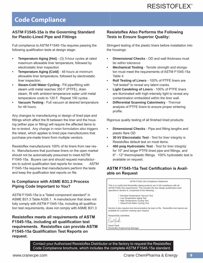
ASTM F1545-15a Compliance Statement
Elevated Temperature Vacuum TestLow Temperature Aging TestHigh Temperature Cycling TestSteam/Cold Water Cycling Test
Section 6 also requires test documentation be kept on file. Resistoflex test reports are available for customer viewing upon request.
Respectfully submitted,
David YanikResistoflex Engineering Manager
Resisto�ex provides technical assistance andsolutions to its customers in local marketsworldwide
•
•
This is to certify that Resistoflex piping products are in full compliance with all ASTM F1545-15a requirements. This includes the four design qualification tests specified in Section 6, comprisied of the following:

10 Crane ChemPharma & Energy www.cranecpe.com
Grounding - External and Internal
Grounding Studs
Grounding Stud
External Grounding
Pipe and fittings can be specified with threaded grounding studs, or other connection method, as part of a grounding/continuity strategy for plastic-lined pipe and fittings.
The design and installation of "jumper" cables and connectorsto each pipe and fitting and grounding points is the scopeof the end user or design engineer.
Pipe and fittings can also be provided with an electrically-conductive paint .
Internal Grounding
Non-conductive fluids can generate a static charge when flowing through a standard PTFE-lined piping system due to the fact that PTFE is electrically insulating. Under certain conditions, conductive and semi-conductive fluids can also generate a static charge. Without dissapative methods, the static charge can build to a level high enough to exceed the dielectric strength of the PTFE liner. This can cause an electrostatic discharge that can arc through the liner, causing liner damage (pinholes) and loss of containment.
Steps can be taken to reduce this condition by limiting fluid velocity in PTFE lined piping as follows:
These values may not be practical, however, due to productivity demands. Where higher flows are necessary, pinholes can be avoided by the prevention of charge accumulation.
The end user can install metal grounding rings or paddles at flange connections to route static charge to grounding points. The paddle material must be compatible with the service fluid. The number and frequency of paddles is determined by the design engineeror a third-party engineer specializing in electrostatic hazard mitigation.
PTFE liner can also be specified as "Anti-Static" or conductive, which is made by adding a small amount of carbon black to the PTFE resin during the liner manufacturing process. The anti-static PTFE has a surface resistivity of 104 to 108 Ohm. The static charge will dissipate through the liner to the metal housing, rather than accumulating on the surface of the liner.
Liquid Conductivity Recommended Flow Velocity For PTFE lined piping
1,000 - 10,000 pS/m less than 9.9 f/s (3 m/s)50 - 1,000 pS/m less than 6.6 f/s (2 m/s)less than 50 pS/m less than 3.3 f/s (1 m/s)

11www.cranecpe.com Crane ChemPharma & Energy
Engineering Support Services
Welded Supports
Bill of Material Take-Off for Quotes
Resistoflex can generate a bill of material from customer isometric drawings or orthographic drawings at no charge. Bills of materials from orthographic drawings will be marked as "budgetary". Drawings can be submitted in PDF or *.dwg format.
Resistoflex Isometric Drawing Service
We can develop isometric drawings from customer orthographic drawings, or from hand-sketches of field measurements. This is a fee-based service.
Installation Training Certification
Plastic-lined pipe and fittings are installed like other flanged piping systems, with emphasis placed on using calibrated torque wrenches and following the manufacturer's torque requirements. For installers that are unfamiliar with plastic-lined pipe installation, or would like a refesher course, we offer on-site installation training and certification.
Field Fabrication Training Certification
Resistoflex offers three styles of lined pipe - Thermalok, Swaged, and CONQUEST®, all of which can be field-fabricated at site using tooling and procedures provided by Resistoflex. We strongly recommend that operators be trained and certified before beginning field fabrication.
For more information regarding Engineering Support Services, contact your Resistoflex Distributor or the factory.
Welded attachments cannot be applied to lined pipeat the site, or liner damage will result. Resistoflex can provide shop-welded supports that are attached to the pipe or fitting prior to lining.
Typical types of welded supports are as shown, with other examples as follows:
Piping designers are requested to provide engineering support details to Resistoflex at the time of quotation.
• Shoes• Clips• Stops• Trunnions• Dummy legs• Reinforcing pads
12 Crane ChemPharma & Energy www.cranecpe.com
Standard and Custom Coatings
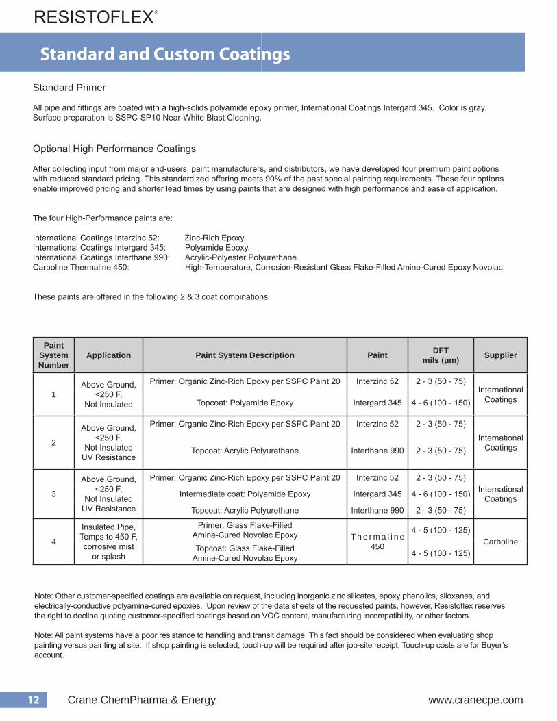
Standard Primer
All pipe and fittings are coated with a high-solids polyamide epoxy primer, International Coatings Intergard 345. Color is gray. Surface preparation is SSPC-SP10 Near-White Blast Cleaning.
Optional High Performance Coatings
After collecting input from major end-users, paint manufacturers, and distributors, we have developed four premium paint options with reduced standard pricing. This standardized offering meets 90% of the past special painting requirements. These four options enable improved pricing and shorter lead times by using paints that are designed with high performance and ease of application.
The four High-Performance paints are:
International Coatings Interzinc 52: Zinc-Rich Epoxy. International Coatings Intergard 345: Polyamide Epoxy. International Coatings Interthane 990: Acrylic-Polyester Polyurethane. Carboline Thermaline 450: High-Temperature, Corrosion-Resistant Glass Flake-Filled Amine-Cured Epoxy Novolac.
These paints are offered in the following 2 & 3 coat combinations.
Note: Other customer-specified coatings are available on request, including inorganic zinc silicates, epoxy phenolics, siloxanes, and electrically-conductive polyamine-cured epoxies. Upon review of the data sheets of the requested paints, however, Resistoflex reserves the right to decline quoting customer-specified coatings based on VOC content, manufacturing incompatibility, or other factors.
Note: All paint systems have a poor resistance to handling and transit damage. This fact should be considered when evaluating shop painting versus painting at site. If shop painting is selected, touch-up will be required after job-site receipt. Touch-up costs are for Buyer’s account.
PaintSystem Number
Application Paint System Description Paint DFTmils (μm) Supplier
1Above Ground,
<250 F, Not Insulated
Primer: Organic Zinc-Rich Epoxy per SSPC Paint 20 Interzinc 52 2 - 3 (50 - 75)International
CoatingsTopcoat: Polyamide Epoxy Intergard 345 4 - 6 (100 - 150)
2
Above Ground, <250 F,
Not InsulatedUV Resistance
Primer: Organic Zinc-Rich Epoxy per SSPC Paint 20 Interzinc 52 2 - 3 (50 - 75)
InternationalCoatingsTopcoat: Acrylic Polyurethane Interthane 990 2 - 3 (50 - 75)
3
Above Ground, <250 F,
Not InsulatedUV Resistance
Primer: Organic Zinc-Rich Epoxy per SSPC Paint 20 Interzinc 52 2 - 3 (50 - 75)International
CoatingsIntermediate coat: Polyamide Epoxy Intergard 345 4 - 6 (100 - 150)
Topcoat: Acrylic Polyurethane Interthane 990 2 - 3 (50 - 75)
4
Insulated Pipe, Temps to 450 F, corrosive mist
or splash
Primer: Glass Flake-Filled Amine-Cured Novolac Epoxy T h e r m a l i n e
450
4 - 5 (100 - 125)Carboline
Topcoat: Glass Flake-Filled Amine-Cured Novolac Epoxy 4 - 5 (100 - 125)

13www.cranecpe.com Crane ChemPharma & Energy
ASME B16.5 Flange DimensionsClass 150 Class 300
SizeNPS (DN)
OutsideDiameterin. (mm)
Thicknessin. (mm)
No. and Diameter
of Bolt Holes
Bolt CircleDiameterin. (mm)
OutsideDiameterin. (mm)
Thicknessin. (mm)
No. and Diameter
of Bolt Holes
Bolt CircleDiameterin. (mm)
1/2 (15) 3 1/2 (88.9) 7/16 (11.2) (4) 5/8 2 3/8 (60.3) 3 3/4 (95.3) 9/16 (14.3) (4) 5/8 2 5/8 (66.7)
3/4 (20) 3 7/8 (98.4) 1/2 (12.7) (4) 5/8 2 3/4 (69.9) 4 5/8 (117.5) 5/8 (15.9) (4) 3/4 3 1/4 (82.6)
1 (25) 4 1/4 (107.9) 9/16 (14.3) (4) 5/8 3 1/8 (79.4) 4 7/8 (123.8) 11/16 (17.5) (4) 3/4 3 1/2 (88.9)
1 1/2 (40) 5 (127) 11/16 (17.5) (4) 5/8 3 7/8 (98.4) 6 1/8 (155.6) 13/16 (20.6) (4) 7/8 4 1/2 (114.3)
2 (50) 6 (152.4) 3/4 (19.1) (4) 3/4 4 3/4 (120.7) 6 1/2 (165.1) 7/8 (22.2) (8) 3/4 5 (127)
3 (80) 7 1/2 (190.5) 15/16 (23.9) (4) 3/4 6 (152.4) 8 1/4 (206.4) 1 1/8 (28.6) (8) 7/8 6 5/8 (168.3)
4 (100) 9 (228.6) 15/16 (23.9) (8) 3/4 7 1/2 (190.5) 10 (254) 1 1/4 (31.8) (8) 7/8 7 7/8 (200)
6 (150) 11 (279.4) 1 (25.4) (8) 7/8 9 1/2 (241.3) 12 1/2 (317.5) 1 7/16 (36.5) (12) 7/8 10 5/8 (269.9)
8 (200) 13 1/2 (342.9) 1 1/8 (28.6) (8) 7/8 11 3/4 (298.5) 15 (381) 1 5/8 (41.3) (12) 1 13 (330.2)
10 (250) 16 (406.4) 1 3/16 (30.2) (12) 1 14 1/4 (362) 17 1/2 (444.5) 1 7/8 (47.6) (16) 1 1/8 15 1/4 (387.4)
12 (300) 19 (482.6) 1 1/4 (31.8) (12) 1 17 (431.8) 20 1/2 (520.7) 2 (50.8) (16) 1 1/4 17 3/4 (450.9)
14 (350) 21 (533.4) 1 3/8 (35) (12) 1 1/8 18 3/4 (476.3) 23 (584.2) 2 1/8 (54) (20) 1 1/4 20 1/4 (514.4)
16 (400) 23 1/2 (596.9) 1 7/16 (36.6) (16) 1 1/8 21 1/4 (539.8) 25 1/2 (647.7) 2 1/4 (57.2) (20) 1 3/8 22 1/4 (571.5)
18 (450) 25 (635) 1 9/16 (39.7) (16) 1 1/4 22 3/4 (577.9) 28 (711.2) 2 3/8 (60.3) (24) 1 3/8 24 3/4 (628.7)
20 (500) 27 1/2 (698.5) 1 1/16 (42.9) (20) 1 1/4 25 (635) 30 1/2 (774.7) 2 1/2 (63.5) (24) 1 3/8 27 (685.8)
24 (600) 32 (812.8) 1 7/8 (47.7) (20) 1 3/8 29 1/2 (749.3) 36 (914.4) 2 3/4 (69.9) (24) 1 5/8 32 (812.8)
ASME B36.10 Pipe DimensionsClass 150 Wall Thickness in. (mm)
SizeNPS (DN)
OutsideDiameterin. (mm)
Sch. 40 Sch. 30 Sch. 20 Sch. STD
1/2 (15) 0.840 (21.3) 0.109 (2.8) - - - - - -
3/4 (20) 1.050 (26.7) 0.113 (2.9) - - - - - -
1 (25) 1.315 (33.4) 0.133 (3.4) - - - - - -
1 1/2 (40) 1.900 (48.3) 0.145 (3.7) - - - - - -
2 (50) 2.375 (60.3) 0.154 (3.9) - - - - - -
3 (80) 3.500 (88.9) 0.216 (5.5) - - - - - -
4 (100) 4.500 (114.3) 0.237 (6) - - - - - -
6 (150) 6.625 (168.3) 0.280 (7.1) - - - - - -
8 (200) 8.625 (219.1) 0.322 (8.2) - - - - - -
10 (250) 10.750 (273) - - 0.307 (7.8) - - - -
12 (300) 12.750 (323.8) - - - - 0.250 (6.4) - -
14 (350) 14.000 (355.6) - - - - - - 0.375 (9.5)
16 (400) 16.000 (406.4) - - - - - - 0.375 (9.5)
18 (450) 18.000 (457.2) - - - - - - 0.375 (9.5)
20 (500) 20.000 (508) - - - - - - 0.375 (9.5)
24 (600) 24.000 (609.6) - - - - - - 0.375 (9.5)
Flange and Pipe Dimensional Data

14 Crane ChemPharma & Energy www.cranecpe.com
Pressure Ratings and Liner Data
Plastic-Liner Data
PTFE = polytetrafluoroethylenePFA = perfluoroalkoxy
PP = polypropylenePVDF = polyvinylidene fluoride
ETFE = ethylene tetrafluoroethylene
1 Max. allowable temperature depends on the specific contact chemicals. 2 Available unpigmented as a special option.
scitsiretcarahCreniL EFTP AFP PP FDVP)remylopomoh(
FDVP)remylopoc( EFTE
F°,egnaRerutarepmeTecivreS 1 F°054otF°02- F°054otF°0 F°522otF°0 F°572otF°0 F°572otF°02- F°003otF°02-
roloCreniL etihW larutaN egnarO kcalB kcalB 3 larutaN
dnaBnoitacifitnedIreniLforoloC htiwetihWgniretteLkcalB
2 2
/wnworBgniretteLetihW
/wegnarOgniretteLkcalB
etihW/wkcalBgniretteL
etihW/wkcalBgniretteL
etihW/wyarGgniretteL
epiPfonoisnapxElamrehTfotneiciffeoC/.ni/.ni,gniniLotroirPreniL F° 01x5.5 5- 01x8.7 5- 01x8.4 5- 01x6.6 5- 01x8.7 5- 01x4.7 5-
tivitcudnoClamrehT y,reniLfo)rotcaF"K"( B -.tf.qs-.rh/.ni-UT F° 7.1 3.1 8.0 9.0 81.1 56.1
isp,dleiYtareniLfohtgnertSelisneT 000,4-000,3 005,4-008,3 005,4-000,4 000,6-000,5 005,5-005,4 0076
%,dleiYtareniLfonoitagnolE 053-052 053-003 31-01 01-8 02-01 003-051
isp,dleiYtareniLfohtgnertSevisserpmoC 007,1 005,3 000,8-005,5 000,61-000,01 0058-0005 005,2
reniLfoytivarGcificepS 91.2-41.2 71.2-21.2 29.0-09.0 87.1-57.1 87.1-67.1 27.1-07.1
TemperatureoF (oC)
Pressure Class and Flange Material
Class 150Ductile Ironpsig (barg)
Class 150Carbon Steelpsig (barg)
Class 150Stainless SteelType 304L/316L
psig (barg)
Class 300 Carbon Steelpsig (barg)
0 (-18) 250 (17.2) 285 (19.7) 230 (15.9) 485 (33.4)
50 (10) 250 (17.2) 285 (19.7) 230 (15.9) 485 (33.4)
100 (38) 250 (17.2) 285 (19.7) 230 (15.9) 485 (33.4)
150 (65) 242 (16.7) 275 (19.1) 212 (14.6) 485 (33.4)
200 (93) 235 (16.2) 260 (17.9) 195 (13.4) 475 (32.8)
250 (121) 225 (15.5) 245 (16.9) 185 (12.8) 460 (31.7)
300 (149) 215 (14.8) 230 (15.9) 175 (12.1) 450 (31.1)
350 (177) 207 (14.3) 215 (14.8) 167 (11.5) 440 (30.3)
400 (204) 200 (13.8) 200 (13.8) 160 (11.1) 425 (29.3)
450 (232) 185 (12.8) 185 (12.8) 155 (10.7) 405 (27.9)
The pressure/temperature ratings of Resistoflex Plastic-Lined Piping Products conform to ASME B16.5 Class 150 per the appropriate flange metallurgy. See Figure 1. The pressure/temperature ratings for lined piping with ASME B16.5 Class 300 flanges are lower than the true Class 300 ratings due the plastic raised face gasket sealing surface on lined pipe and fittings.
Standard 1" - 12" PTFE-lined pipe and fittings are rated for full vacuum at 450 F (230 C) continuous. There are a few fittings that are not rated for full vacuum to 450 F - the vacuum ratings of all 1" - 12" PTFE-lined fittings are indicated on the product pages in this de-sign manual. PP and PVDF-lined pipe and fittings are rated for full vacuum to 225 F (107 C) and 275 F (135 C), respectively.
14" - 18" PTFE-lined pipe and fittings have limited vacuum resistance. Please consult Resistoflex for specific capabilities. 20" - 24" PTFE-lined pipe and fittings are not rated for vacuum service.
Figure 1: Pressure ratings for Resistoflex 1" - 24" pipe and fittings
15www.cranecpe.com Crane ChemPharma & Energy
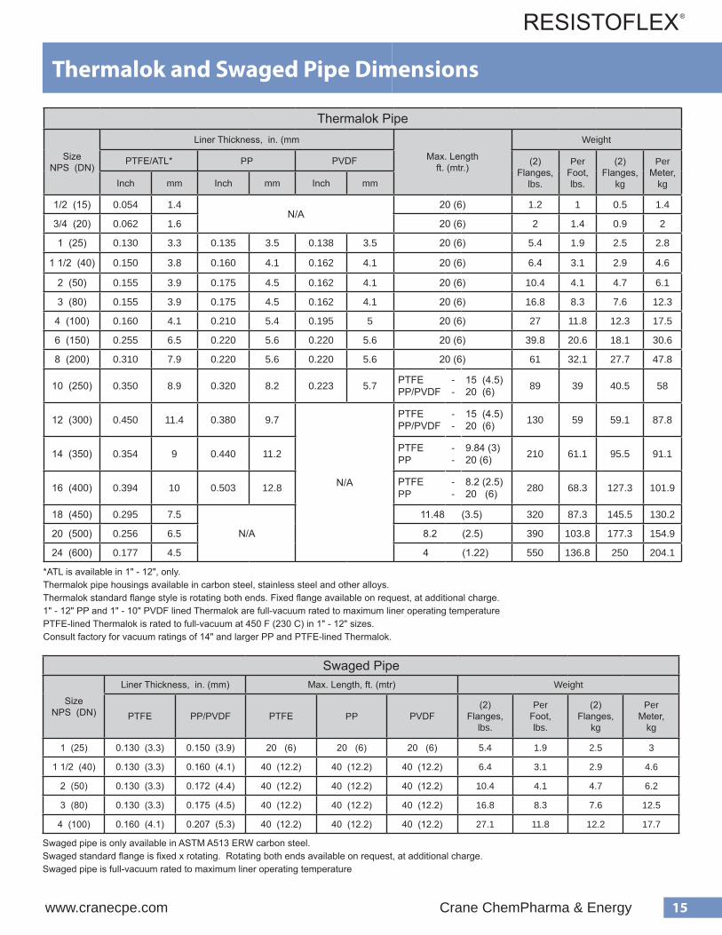
Thermalok Pipe
Size NPS (DN)
Liner Thickness, in. (mm
Max. Lengthft. (mtr.)
Weight
PTFE/ATL* PP PVDF (2) Flanges,
lbs.
Per Foot, lbs.
(2) Flanges,
kg
Per Meter,
kgInch mm Inch mm Inch mm
1/2 (15) 0.054 1.4N/A
20 (6) 1.2 1 0.5 1.4
3/4 (20) 0.062 1.6 20 (6) 2 1.4 0.9 2
1 (25) 0.130 3.3 0.135 3.5 0.138 3.5 20 (6) 5.4 1.9 2.5 2.8
1 1/2 (40) 0.150 3.8 0.160 4.1 0.162 4.1 20 (6) 6.4 3.1 2.9 4.6
2 (50) 0.155 3.9 0.175 4.5 0.162 4.1 20 (6) 10.4 4.1 4.7 6.1
3 (80) 0.155 3.9 0.175 4.5 0.162 4.1 20 (6) 16.8 8.3 7.6 12.3
4 (100) 0.160 4.1 0.210 5.4 0.195 5 20 (6) 27 11.8 12.3 17.5
6 (150) 0.255 6.5 0.220 5.6 0.220 5.6 20 (6) 39.8 20.6 18.1 30.6
8 (200) 0.310 7.9 0.220 5.6 0.220 5.6 20 (6) 61 32.1 27.7 47.8
10 (250) 0.350 8.9 0.320 8.2 0.223 5.7 PTFEPP/PVDF
--
15 (4.5)20 (6) 89 39 40.5 58
12 (300) 0.450 11.4 0.380 9.7
N/A
PTFEPP/PVDF
--
15 (4.5)20 (6) 130 59 59.1 87.8
14 (350) 0.354 9 0.440 11.2 PTFEPP
--
9.84 (3)20 (6) 210 61.1 95.5 91.1
16 (400) 0.394 10 0.503 12.8 PTFEPP
--
8.2 (2.5)20 (6) 280 68.3 127.3 101.9
18 (450) 0.295 7.5
N/A
11.48 (3.5) 320 87.3 145.5 130.2
20 (500) 0.256 6.5 8.2 (2.5) 390 103.8 177.3 154.9
24 (600) 0.177 4.5 4 (1.22) 550 136.8 250 204.1
*ATL is available in 1" - 12", only.Thermalok pipe housings available in carbon steel, stainless steel and other alloys. Thermalok standard flange style is rotating both ends. Fixed flange available on request, at additional charge.1" - 12" PP and 1" - 10" PVDF lined Thermalok are full-vacuum rated to maximum liner operating temperaturePTFE-lined Thermalok is rated to full-vacuum at 450 F (230 C) in 1" - 12" sizes. Consult factory for vacuum ratings of 14" and larger PP and PTFE-lined Thermalok.
Thermalok and Swaged Pipe Dimensions
Swaged Pipe
Size NPS (DN)
Liner Thickness, in. (mm) Max. Length, ft. (mtr) Weight
PTFE PP/PVDF PTFE PP PVDF(2)
Flanges,lbs.
Per Foot, lbs.
(2) Flanges,
kg
Per Meter,
kg
1 (25) 0.130 (3.3) 0.150 (3.9) 20 (6) 20 (6) 20 (6) 5.4 1.9 2.5 3
1 1/2 (40) 0.130 (3.3) 0.160 (4.1) 40 (12.2) 40 (12.2) 40 (12.2) 6.4 3.1 2.9 4.6
2 (50) 0.130 (3.3) 0.172 (4.4) 40 (12.2) 40 (12.2) 40 (12.2) 10.4 4.1 4.7 6.2
3 (80) 0.130 (3.3) 0.175 (4.5) 40 (12.2) 40 (12.2) 40 (12.2) 16.8 8.3 7.6 12.5
4 (100) 0.160 (4.1) 0.207 (5.3) 40 (12.2) 40 (12.2) 40 (12.2) 27.1 11.8 12.2 17.7
Swaged pipe is only available in ASTM A513 ERW carbon steel.Swaged standard flange is fixed x rotating. Rotating both ends available on request, at additional charge.Swaged pipe is full-vacuum rated to maximum liner operating temperature

16 Crane ChemPharma & Energy www.cranecpe.com
s e h c n i n i h t g n e L l o o p S e p i P m u m i n i M k o l a m r e h T 3 s s a l C
e z i S ) S P N (
s n o i t p O o N s d u t S g n i d n u o r G r o s g n i l p u o C t n e V h t i W 0 5 1
0 5 1 s s a l C 0 0 3 s s a l C 0 5 1 s s a l C 0 0 3 s s a l C e r a l F d l e i F 4
Minimum Flanged Pipe Spool Lengths
Distance PieceFor filling spaces greater in lengththan the maximum spacer (3”) butless than the minimum flanged pipespool, a distance piece is used. Adistance piece does not haveflanges, but is held in place by usinglong bolts or studs between theadjacent flanges.
1 Available only as fixed flange spools. 2 Capability of field threaders, such as Wheeler Rex or equal, 8” size requires alternate method of threading. Wheeler Rex will only thread up through 6”. Minimum spool lengths for flange one end piping is 3 ft. when using a Wheeler Rex machine.
3Thermalok minimum lengths can be reduced by using fixed flanges at one or both ends at an additional cost.
4When using a pipe end forming machine such as a Conrac by PHI. Min. length assumes no welding of stubends. Consult factory for details.
sehcnInishtgneLloopSepiPmuminiMdegawS
eziS)SPN(
dradnatS laicepS 1
dleiF 2
051ssalC 003ssalC 051ssalC 003ssalC
1 4 4 2/12 2/12 7
2/11 4 4 4/32 4/32 7
2 2/14 2/14 8/13 8/13 7
3 5 5 2/13 2/13 8
4 2/15 2/15 4/33 4/33 8
6 2/15 2/15 8/14 8/14 01
8 7 7 2/14 2/14 21
1 3 8 / 5 3 8 / 1 4 8 / 7 4 2 / 1 5
2 / 1 1 8 / 3 3 4 8 / 5 4 8 / 1 5 7
2 2 / 1 3 4 / 1 4 8 / 7 4 2 / 1 5 8
3 4 8 / 1 5 8 / 3 5 8 / 3 6 8 / 5 0 1
4 8
1/2 3 3 1/4 3 7/8 4 3/8 N/A
N/A 3 3 3/8 3 7/8 4 1/2 3/4
/ 3 4 2 / 1 5 8 / 5 5 4 / 3 6 1 1
6 2 / 1 5 8 / 3 6 2 / 1 6 2 / 1 7 2 / 1 6 1
8 2 / 1 6 2 / 1 7 7 8 / 3 8 2 / 1 6 1
01 2 / 1 8 8 / 7 9 2 / 1 8 1 1 Consult Factory
Consult Factory12 (PTFE, PP, only) 2 / 1 8 8 / 3 0 1 2 / 1 8 8 / 5 1 1
Length
Minimum Flanged Pipe Spool Lengths
Thermalok Minimum Pipe Spool Lengths
Size NPS (DN)
No Options With Vent Couplings or Grounding StudsClass 150
Field Flare *Class 150 Class 300 Class 150 Class 300
Inch mm Inch mm inch mm inch mm
1 (25) 2 5/8 67 3 3/8 86 3 7/8 98 4 5/8 117 5 1/2 (139.7)
1 1/2 (40) 3 1/8 79 3 3/4 95 4 3/8 111 5 127 7 (177.8)
2 (50) 3 3/8 86 4 102 4 5/8 117 5 1/4 133 8 (203.2)
3 (80) 3 3/4 95 4 3/4 121 5 127 6 152 10 5/8 (269.9)
4 (100) 4 1/4 108 5 3/8 137 5 1/2 140 6 5/8 168 11 (279.4)
6 (150) 4 7/8 124 5 7/8 149 6 1/8 156 7 1/4 181 16 1/2 (419.1)
8 (200) 5 1/4 133 6 5/8 168 6 1/2 165 7 7/8 200 16 1/2 (419.1)
10 (250) 5 7/8 149 8 3/8 213 7 1/8 181 9 5/8 244 Consult Factory
12 (300) 6 1/4 156 8 5/8 219 7 3/8 187 9 7/8 251 Consult Factory
14 (350) 9 7/8 251 10 1/4 260 9 3/4 248 11 3/4 298 N/A
16 (400) 10 1/2 267 10 7/8 276 10 1/4 260 12 3/8 314 N/A
18 (450) 11 1/4 286 11 1/2 292 10 7/8 276 13 330 N/A
20 (500) 11 3/4 298 12 1/8 308 11 1/4 286 13 5/8 346 N/A
24 (600) 12 3/8 314 13 1/8 333 12 305 14 5/8 371 N/A
1/2" and 3/4" consult factoryLengths are with fixed x rotating flanges. Rotating flanges both ends have longer minimum lengths. Shorter lengths available with fixed x fixed flanges.* When using a pipe end forming machine such as a Conrac by PHI, a division of Tulip Corporation. Min. length assumes no welding of stubends.
Swaged Minimum Pipe Spool Lengths
Size NPS (DN)
Standard Special *Field **
Class 150 Class 300 Class 150 Class 300
Inch mm Inch mm inch mm inch mm inch mm
1 (25) 4 102 4 102 2 1/2 64 2 1/2 64 7 178
1 1/2 (40) 4 102 4 102 2 3/4 70 2 3/4 70 7 178
2 (50) 4 1/2 114 4 1/2 114 3 1/8 79 3 1/8 79 7 178
3 (80) 5 127 5 127 3 1/2 89 3 1/2 89 8 203
4 (100) 5 1/2 140 5 1/2 140 3 3/4 95 3 3/4 95 8 203
* Available only as fixed flanged spools** Capability of field threaders, such as Wheeler Rex, or equal

17www.cranecpe.com Crane ChemPharma & Energy
Thermalok Minimum Pipe Spool Lengths
Size NPS (DN)
No Options With Vent Couplings or Grounding StudsClass 150
Field Flare *Class 150 Class 300 Class 150 Class 300
Inch mm Inch mm inch mm inch mm
1 (25) 2 5/8 67 3 3/8 86 3 7/8 98 4 5/8 117 5 1/2 (139.7)
1 1/2 (40) 3 1/8 79 3 3/4 95 4 3/8 111 5 127 7 (177.8)
2 (50) 3 3/8 86 4 102 4 5/8 117 5 1/4 133 8 (203.2)
3 (80) 3 3/4 95 4 3/4 121 5 127 6 152 10 5/8 (269.9)
4 (100) 4 1/4 108 5 3/8 137 5 1/2 140 6 5/8 168 11 (279.4)
6 (150) 4 7/8 124 5 7/8 149 6 1/8 156 7 1/4 181 16 1/2 (419.1)
8 (200) 5 1/4 133 6 5/8 168 6 1/2 165 7 7/8 200 16 1/2 (419.1)
10 (250) 5 7/8 149 8 3/8 213 7 1/8 181 9 5/8 244 Consult Factory
12 (300) 6 1/4 156 8 5/8 219 7 3/8 187 9 7/8 251 Consult Factory
14 (350) 9 7/8 251 10 1/4 260 9 3/4 248 11 3/4 298 N/A
16 (400) 10 1/2 267 10 7/8 276 10 1/4 260 12 3/8 314 N/A
18 (450) 11 1/4 286 11 1/2 292 10 7/8 276 13 330 N/A
20 (500) 11 3/4 298 12 1/8 308 11 1/4 286 13 5/8 346 N/A
24 (600) 12 3/8 314 13 1/8 333 12 305 14 5/8 371 N/A
1/2" and 3/4" consult factoryLengths are with fixed x rotating flanges. Rotating flanges both ends have longer minimum lengths. Shorter lengths available with fixed x fixed flanges.* When using a pipe end forming machine such as a Conrac by PHI, a division of Tulip Corporation. Min. length assumes no welding of stubends.
Swaged Minimum Pipe Spool Lengths
Size NPS (DN)
Standard Special *Field **
Class 150 Class 300 Class 150 Class 300
Inch mm Inch mm inch mm inch mm inch mm
1 (25) 4 102 4 102 2 1/2 64 2 1/2 64 7 178
1 1/2 (40) 4 102 4 102 2 3/4 70 2 3/4 70 7 178
2 (50) 4 1/2 114 4 1/2 114 3 1/8 79 3 1/8 79 7 178
3 (80) 5 127 5 127 3 1/2 89 3 1/2 89 8 203
4 (100) 5 1/2 140 5 1/2 140 3 3/4 95 3 3/4 95 8 203
* Available only as fixed flanged spools** Capability of field threaders, such as Wheeler Rex, or equal
Advanced Technology Liner - Resisto�ex ATL PTFE
Resistoflex ATL is the most cost effective solution for resolving permeation issues in severe service applications.
The permeation rate is 60% lower compared to other available products
Resistoflex ATL provides up to 75% cost savings versus exotic alloys and glass-lined piping
It has zero corrosion rate, and is full vacuum rated
See the website or contactthe factory for the full ATLbrochure
Resistoflex ATL PTFE liners are produced from carefully formulated resins and proprietary processing and lining techniques. The result is a molded PTFE liner that provides optimal crystallinity and strength. ATL PTFE liners provide the best permeation resistance in the industry.
Optimized PTFE liner
Resistoflex ATL PTFE pipe and fittings are designed to minimize any potential permeation attack of the housing by use of an advanced venting system that eliminates blockage and corrosion at the vent hole.
Enhanced venting system
Resistoflex ATL PTFE pipe and fittings are double coated with a highly chemical and temperature resistant paint. This paint is rated to 450°F (232°C) and can be used under insulation.
Highly chemical and temperatureresistant paint system
17www.cranecpe.com Crane ChemPharma & Energy

18 Crane ChemPharma & Energy www.cranecpe.com
20" (DN350) - 24" (DN600) 45 Degree Elbows
Large Diameter (14" - 24") Multipiece Fitting Construction
16" (DN400) - 18" (DN450) 90 Degree Elbows
20" (DN500) - 24" (DN600) 90 Degree Elbows
14" (DN350)- 24" (DN600)Tees, Reducing Tees, Crosses, and Reducing Crosses
14" (DN350) - 24" (DN600) Instrument Tees
Large Diameter elbows and branch fittings are made in a "multipiece" construction as shown below with center-face dimensions as shown on following PTFE-fittings dimensional pages.
14" (DN350) - 24" (DN600) pipe spools can be made with multiple and variously sized branches in this manner.
14" - 24" concentric/eccentric reducers with size reductions of 3 or more line sizes are made with pipe spools and reduc-ing filler flanges.

19www.cranecpe.com Crane ChemPharma & Energy
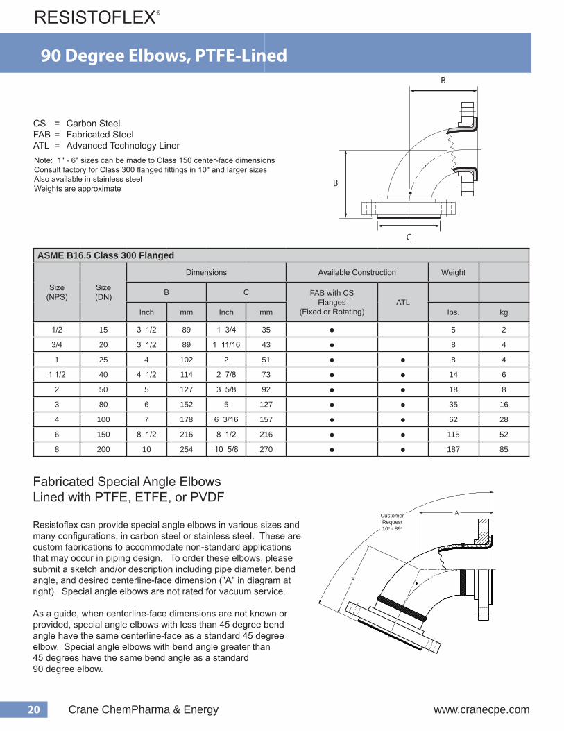
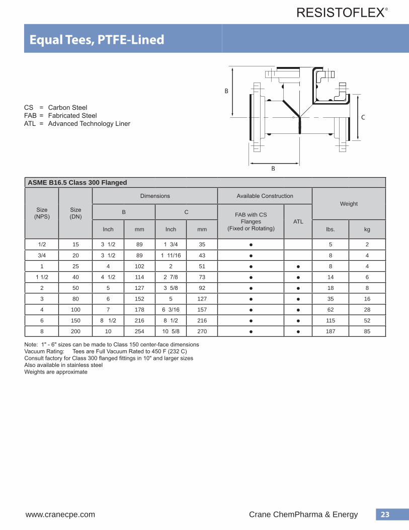
ASME B16.5 Class 150 Flanged
Size(NPS)
Size(DN)
Dimensions Available ConstructionWeight
B C FAB with DI Rotating Flanges
FAB with CS Flanges
(Fixed or Rotating)
CastDI
A395
CastSteelA216 WCB
ATLInch mm Inch mm lbs. kg
1/2 15 3 1/2 89 1 3/4 35 ● 3 1.5
3/4 20 3 1/2 89 1 11/16 43 ● 5 2.1
1 25 3 1/2 89 2 51 ● ● ● ● 6 2.7
1 1/2 40 4 102 2 7/8 73 ● ● ● ● 9 4
2 50 4 1/2 114 3 5/8 92 ● ● ● ● 14 6.4
3 80 5 1/2 140 5 127 ● ● ● ● 26 12
4 100 6 1/2 165 6 3/16 157 ● ● ● ● 42 19
6 150 8 203 8 1/2 216 ● ● ● ● ● 79 36
8 200 9 229 10 5/8 270 ● ● ● ● ● 125 57
10 250 11 279 12 3/4 324 ● ● ● ● ● 180 82
12 300 12 305 15 381 ● ● ● ● ● 244 111
14 350 21 1/2 546 16 1/4 413 ● 363 165
16* 400 24 610 18 1/2 470 ● 422 192
18* 450 26 1/2 673 21 533 ● 517 235
20* 500 29 736 23 584 ● 616 280
24* 600 34 864 27 1/4 692 ● 869 395
Note: Cast steel elbows are more economical than fabricated steel in 6" - 10" sizes.Vacuum Rating: 1" - 12" is Full Vacuum Rated to 450 F (232 C) 14" - 24" = Consult Factory
Also available in stainless steel Weights are approximate
*Multi-Piece Construction - See Page 18
90 Degree Elbows, PTFE-Lined
CS = Carbon SteelDI = Ductile IronFAB = Fabricated SteelATL = Advanced Technology Liner
20 Crane ChemPharma & Energy www.cranecpe.com
ASME B16.5 Class 300 Flanged
Size(NPS)
Size(DN)
Dimensions Available Construction Weight
B C FAB with CS Flanges
(Fixed or Rotating)ATL
Inch mm Inch mm lbs. kg
1/2 15 3 1/2 89 1 3/4 35 ● 5 2
3/4 20 3 1/2 89 1 11/16 43 ● 8 4
1 25 4 102 2 51 ● ● 8 4
1 1/2 40 4 1/2 114 2 7/8 73 ● ● 14 6
2 50 5 127 3 5/8 92 ● ● 18 8
3 80 6 152 5 127 ● ● 35 16
4 100 7 178 6 3/16 157 ● ● 62 28
6 150 8 1/2 216 8 1/2 216 ● ● 115 52
8 200 10 254 10 5/8 270 ● ● 187 85
Note: 1" - 6" sizes can be made to Class 150 center-face dimensionsConsult factory for Class 300 flanged fittings in 10" and larger sizesAlso available in stainless steel Weights are approximate
CS = Carbon SteelFAB = Fabricated SteelATL = Advanced Technology Liner
90 Degree Elbows, PTFE-Lined
Fabricated Special Angle ElbowsLined with PTFE, ETFE, or PVDF
Resistoflex can provide special angle elbows in various sizes and many configurations, in carbon steel or stainless steel. These are custom fabrications to accommodate non-standard applications that may occur in piping design. To order these elbows, please submit a sketch and/or description including pipe diameter, bend angle, and desired centerline-face dimension ("A" in diagram at right). Special angle elbows are not rated for vacuum service.
As a guide, when centerline-face dimensions are not known or provided, special angle elbows with less than 45 degree bend angle have the same centerline-face as a standard 45 degree elbow. Special angle elbows with bend angle greater than 45 degrees have the same bend angle as a standard 90 degree elbow.
Customer Request10o - 89o
21www.cranecpe.com Crane ChemPharma & Energy
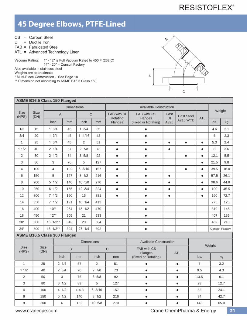
ASME B16.5 Class 150 Flanged
Size(NPS)
Size(DN)
Dimensions Available ConstructionWeight
A C FAB with DI Rotating Flanges
FAB with CS Flanges
(Fixed or Rotating)
CastDI
A395
Cast SteelA216 WCB ATL
Inch mm Inch mm lbs. kg
1/2 15 1 3/4 45 1 3/4 35 ● 4.6 2.1
3/4 20 1 3/4 45 1 11/16 43 ● 5 2.3
1 25 1 3/4 45 2 51 ● ● ● ● ● 5.3 2.4
1 1/2 40 2 1/4 57 2 7/8 73 ● ● ● ● 8 3.6
2 50 2 1/2 64 3 5/8 92 ● ● ● ● 12.1 5.5
3 80 3 76 5 127 ● ● ● 21.5 9.8
4 100 4 102 6 3/16 157 ● ● ● ● 39.5 18.0
6 150 5 127 8 1/2 216 ● ● ● ● 57.5 26.1
8 200 5 1/2 140 10 5/8 270 ● ● ● ● 98.6 44.8
10 250 6 1/2 165 12 3/4 324 ● ● ● ● 100 45.5
12 300 7 1/2 190 15 381 ● ● ● ● 160 72.7
14 350 7 1/2 191 16 1/4 413 ● 275 125
16 400 10** 254 18 1/2 470 ● 319 145
18 450 12** 305 21 533 ● 407 185
20* 500 13 1/2** 343 23 584 ● 462 210
24* 500 15 1/2** 394 27 1/4 692 ● Consult Factory
45 Degree Elbows, PTFE-Lined
Vacuum Rating: 1" - 12" is Full Vacuum Rated to 450 F (232 C)14" - 20" = Consult Factory
Also available in stainless steelWeights are approximate* Multi-Piece Construction - See Page 18** Dimension not according to ASME B16.5 Class 150.
CS = Carbon SteelDI = Ductile IronFAB = Fabricated SteelATL = Advanced Technology Liner
ASME B16.5 Class 300 Flanged
Size(NPS)
Size(DN)
Dimensions Available ConstructionWeight
B C FAB with CS Flanges
(Fixed or Rotating)ATL
Inch mm Inch mm lbs. kg
1 25 2 1/4 57 2 51 ● ● 7 3.2
1 1/2 40 2 3/4 70 2 7/8 73 ● ● 9.5 4.3
2 50 3 76 3 5/8 92 ● ● 13.5 6.1
3 80 3 1/2 89 5 127 ● ● 28 12.7
4 100 4 1/2 114.3 6 3/16 157 ● ● 53 24.1
6 150 5 1/2 140 8 1/2 216 ● ● 94 42.7
8 200 6 152 10 5/8 270 ● ● 143 65.0

22 Crane ChemPharma & Energy www.cranecpe.com
ASME B16.5 Class 150 Flanged
Size(NPS)
Size(DN)
Dimensions Available ConstructionWeight
B C FAB with DI Rotating Flanges
FAB with CS Flanges
(Fixed or Rotating)ATL
Inch mm Inch mm lbs. kg
1/2* 15 3 1/2 89 1 3/4 35 ● 5.5 2.5
3/4* 20 3 1/2 89 1 11/16 43 ● 7 3.2
1 25 3 1/2 89 2 51 ● ● ● 10 4.5
1 1/2 40 4 102 2 7/8 73 ● ● ● 14 6.4
2 50 4 1/2 114 3 5/8 92 ● ● ● 19.5 8.9
3 80 5 1/2 140 5 127 ● ● ● 40 18.2
4 100 6 1/2 165 6 3/16 157 ● ● ● 67 30.5
6 150 8 203 8 1/2 216 ● ● ● 120 54.5
8 200 9 229 10 5/8 270 ● ● ● 180 81.8
10 250 11 279 12 3/4 324 ● ● ● 219 99.5
12 300 12 305 15 381 ● ● ● 318 144.5
14** 350 14 356 16 1/4 412 ● 686 312
16** 400 15 381 18 1/2 470 ● 825 375
18** 450 16 1/2 419 21 534 ● 880 400
20** 500 18 457 23 585 ● 924 420
24** 600 22 559 27 1/4 692 ● 1276 580
Vacuum Rating: 1" - 12" is Full Vacuum Rated to 450 F (232 C) 14" - 24" = Consult FactoryAlso available in stainless steelWeights are approximate
Note: Tees are available with shortened branch or run dimensions. Please consult factory with custom requirements.
* PFA-lined**Multi-Piece Construction - See Page 18
Equal Tees, PTFE-Lined
CS = Carbon SteelDI = Ductile IronFAB = Fabricated SteelATL = Advanced Technology Liner
23www.cranecpe.com Crane ChemPharma & Energy
ASME B16.5 Class 300 Flanged
Size(NPS)
Size(DN)
Dimensions Available ConstructionWeight
B C FAB with CS Flanges
(Fixed or Rotating)ATL
Inch mm Inch mm lbs. kg
1/2 15 3 1/2 89 1 3/4 35 ● 5 2
3/4 20 3 1/2 89 1 11/16 43 ● 8 4
1 25 4 102 2 51 ● ● 8 4
1 1/2 40 4 1/2 114 2 7/8 73 ● ● 14 6
2 50 5 127 3 5/8 92 ● ● 18 8
3 80 6 152 5 127 ● ● 35 16
4 100 7 178 6 3/16 157 ● ● 62 28
6 150 8 1/2 216 8 1/2 216 ● ● 115 52
8 200 10 254 10 5/8 270 ● ● 187 85
Note: 1" - 6" sizes can be made to Class 150 center-face dimensionsVacuum Rating: Tees are Full Vacuum Rated to 450 F (232 C)Consult factory for Class 300 flanged fittings in 10" and larger sizesAlso available in stainless steelWeights are approximate
Equal Tees, PTFE-Lined
CS = Carbon SteelFAB = Fabricated SteelATL = Advanced Technology Liner

24 Crane ChemPharma & Energy www.cranecpe.com
Reducing Tees, PTFE-Lined
ASME B16.5 Class 150 Flanged
Major SizeNPS (DN)
Minor Size
NPS (DN)
Dimensions Available ConstructionWeight
B C D FAB with DI Rotating Flanges
FAB with CS Flanges
(Fixed or Rotating)ATL
Inch mm Inch mm Inch mm lbs. kg
1 (25)1/2 (15)*
3 1/2 89 2 511 3/4 35 Fixed 8 3.6
3/4 (20)* 1 11/16 43 Fixed 9 4.1
1 1/2 (40)
1/2 (15)*4 102 2 7/8 73
1 3/4 35 Fixed 9 4.1
3/4 (20)* 1 11/16 43 Fixed 10 4.5
1 (25) 2 51 ● ● ● 12.2 5.5
2 (50)1 (25)
4 1/2 114 3 5/8 922 51 ● ● ● 16.2 7.4
1 1/2 (40) 2 7/8 73 ● ● ● 17.6 8.0
3 (80)
1 (25)
5 1/2 140 5 127
2 51 ● ● ● 31 14.1
1 1/2 (40) 2 7/8 73 ● ● ● 32.2 14.6
2 (50) 3 5/8 92 ● ● ● 34 15.5
4 (100)
1 (25)
6 1/2 165 6 3/16 157
2 51 ● ● ● 45.5 20.7
1 1/2 (40) 2 7/8 73 ● ● ● 56.2 25.5
2 (50) 3 5/8 92 ● ● ● 57 25.9
3 (80) 5 127 ● ● ● 57.7 26.2
6 (150)
2 (50)
8 203 8 1/2 216
3 5/8 92 ● ● ● 90.8 41.3
3 (80) 5 127 ● ● ● 80 36.4
4 (100) 6 3/16 157 ● ● ● 105.6 48.0
8 (200)
3 (80)
9 229 10 5/8 270
5 127 ● ● ● 162 73.6
4 (100) 6 3/16 157 ● ● ● 165.5 75.2
6 (150) 8 1/2 216 ● ● ● 170.3 77.4
10 (250)6 (150)
11 279 12 3/4 3248 1/2 216 ● ● ● 250 113.6
8 (200) 10 5/8 270 ● ● ● 260 118.2
CS = Carbon SteelDI = Ductile IronFAB = Fabricated SteelATL = Advanced Technology Liner Vacuum Rating: 1" - 12" is Full Vacuum Rated to 450 F (232 C)Also available in stainless steelWeights are approximate* PFA-Lined

25www.cranecpe.com Crane ChemPharma & Energy
Reducing Tees, PTFE-Lined
ASME B16.5 Class 150 Flanged
Major SizeNPS (DN)
Minor SizeNPS (DN)
Dimensions Available ConstructionWeight
B C D FAB with DI Rotating Flanges
FAB with CS Flanges
(Fixed or Rotating)ATL
Inch mm Inch mm Inch mm lbs. kg
12 (300)
4 (100)
12 305 15 381
6 3/16 157 ● ● ● 260 118.2
6 (150) 8 1/2 216 ● ● ● 270 122.7
8 (200) 10 5/8 270 ● ● ● 280 127.3
10 (250) 12 3/4 324 ● ● ● 290 131.8
14 (350)*
8 (200)
14 356 16 1/4 412
10 5/8 270 ● 646.8 294
10 (250) 12 3/4 324 ● 660 300
12 (300) 15 381 ● 677.6 308
16 (400)*
10 (250)
15 381 18 1/2 470
12 3/4 324 ● 783.2 356
12 (300) 15 381 ● 796.4 362
14 (350) 16 1/4 412 ● 814 370
18 (450)*
12 (300)
16 1/2 419 21 534
15 381 ●
ConsultFactory
14 (350) 16 1/4 412 ●16 (400) 18 1/2 470 ●
20 (500)*
14 (350)
18 457 23 585
16 1/4 412 ●16 (400) 18 1/2 470 ●18 (450) 21 534 ●
24 (600)*
16 (400)
22 559 27 1/4 692
18 1/2 470 ●18 (450) 21 534 ●20 (500) 23 585 ●
Vacuum Rating: 1" - 12" is Full Vacuum Rated to 450 F (232 C) 14" - 24" = Consult FactoryAlso available in stainless steelWeights are approximate
* Multi-Piece Construction - See Page 18
CS = Carbon SteelDI = Ductile IronFAB = Fabricated SteelATL = Advanced Technology Liner
14" - 24" reducing tee common branch sizes are shown. Branch sizes down to 1" are available.

26 Crane ChemPharma & Energy www.cranecpe.com
Reducing Tees, PTFE-Lined
ASME B16.5 Class 300 Flanged
Major SizeNPS (DN)
Minor SizeNPS (DN)
Dimensions Available ConstructionWeight
B C D FAB with DI Rotating Flanges
FAB with CS Flanges
(Fixed or Rotating)ATL
Inch mm Inch mm Inch mm lbs. kg
1.5 (40) 1 (25) 4 102 2 7/8 73 2 51 ● ● ● 18.5 8.4
2 (50)1 (25)
4 1/2 114 3 5/8 922 51 ● ● ● 21.1 9.6
1.5 (40) 2 7/8 73 ● ● ● 24.3 11
3 (150)
1 (25)
5 1/2 140 5 127
2 51 ● ● ● 41.3 18.8
1.5 (40) 2 7/8 73 ● ● ● 44.3 20.1
2 (50) 3 5/8 92 ● ● ● 45.4 20.6
4 (100)
1.5 (40)
6 1/2 165 6 3/16 157
2 7/8 73 ● ● ● 78.5 35.7
2 (50) 3 5/8 92 ● ● ● 78.6 35.7
3 (80) 5 127 ● ● ● 82 37.3
6 (150)
2 (50)
8 203 8 1/2 216
3 5/8 92 ● ● ● 128.8 58.5
3 (80) 5 127 ● ● ● 120.7 54.9
4 (100) 6 3/16 157 ● ● ● 151.4 68.8
8 (200)
3 (80)
9 229 10 5/8 270
5 127 ● ● ● 222.7 101.2
4 (100) 6 3/16 157 ● ● ● 231.3 105.1
6 (150) 8 1/2 216 ● ● ● 244.3 111
Vacuum Rating: 1" - 12" is Full Vacuum Rated to 450 F (232 C)14" - 24" = Consult Factory
Also available in stainless steelWeights are approximate
CS = Carbon SteelDI = Ductile IronFAB = Fabricated SteelATL = Advanced Technology Liner

27www.cranecpe.com Crane ChemPharma & Energy
Fabricated Two-Piece Reducing Tees, PTFE-Lined
CS = Carbon SteelDI = Ductile IronFAB = Fabricated SteelATL = Advanced Technology Liner
ASME B16.5 Class 150 Flanged
Major SizeNPS (DN)
Minor SizeNPS (DN)
Dimensions Available Construction
B C D FAB with DI Rotating Flanges
FAB with CS Flanges
(Fixed or Rotating)ATL
Inch mm Inch mm Inch mm
6 (150)1 (25)
8 203 8 1/2 2162 51 ● ● ●
1.5 (40) 2 7/8 73 ● ● ●
8 (200)
1 (25)
9 229 10 5/8 270
2 51 ● ● ●1.5 (40) 2 7/8 73 ● ● ●2 (50) 3 5/8 92 ● ● ●
10 (250)
1 (25)
11 279 12 3/4 324
2 51 ● ● ●1.5 (40) 2 7/8 73 ● ● ●2 (50) 3 5/8 92 ● ● ●3 (80) 5 127 ● ● ●
4 (100) 6 3/16 157 ● ● ●
12 (300)
1 (25)
12 305 15 381
2 51 ● ● ●1.5 (40) 2 7/8 73 ● ● ●2 (50) 3 5/8 92 ● ● ●3 (80) 5 127 ● ● ●
Construction is a reducing tee with a shortened stack and a reducing filler flange bolted togetherVacuum Rating = Full at 450 FAlso available in stainless steelConsult factory for weights
28 Crane ChemPharma & Energy www.cranecpe.com
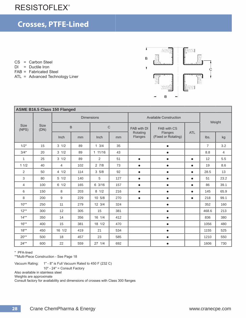
ASME B16.5 Class 150 Flanged
Size(NPS)
Size(DN)
Dimensions Available ConstructionWeight
B C FAB with DI Rotating Flanges
FAB with CS Flanges
(Fixed or Rotating)ATL
Inch mm Inch mm lbs. kg
1/2* 15 3 1/2 89 1 3/4 35 ● 7 3.2
3/4* 20 3 1/2 89 1 11/16 43 ● 8.8 4
1 25 3 1/2 89 2 51 ● ● ● 12 5.5
1 1/2 40 4 102 2 7/8 73 ● ● ● 19 8.6
2 50 4 1/2 114 3 5/8 92 ● ● ● 28.5 13
3 80 5 1/2 140 5 127 ● ● ● 51 23.2
4 100 6 1/2 165 6 3/16 157 ● ● ● 86 39.1
6 150 8 203 8 1/2 216 ● ● ● 145 65.9
8 200 9 229 10 5/8 270 ● ● ● 218 99.1
10** 250 11 279 12 3/4 324 ● 352 160
12** 300 12 305 15 381 ● 468.6 213
14** 350 14 356 16 1/4 412 ● 836 380
16** 400 15 381 18 1/2 470 ● 1056 480
18** 450 16 1/2 419 21 534 ● 1155 525
20** 500 18 457 23 585 ● 1210 550
24** 600 22 559 27 1/4 692 ● 1606 730
Crosses PTFE-Lined Housing Materials FAB STEEL = Housing fabricated from pipe and/or weld fittings
Flange Materials CS = ASTM A105 DI = ASTM A395 Cast Ductile Iron
FV = Full Vacuum
d e g n a l F . b l 0 5 1
e z i S ) S P N ( r e b m u N t r a P
) . n i ( s n o i s n e m i D g n i s u o H l a i r e t a M
s e g n a l F g n i t a R m u u c a V
) F / g H . n i ( B C l a i r e t a M g n i t a t o R = R d e x i F = F
1 0 0 1 V V V V 3 M 0 0 N C
2 / 1 3 2
L E E T S BA F
I D
R
001VZZZ3M0 0 N C S C
5 . 1 0 0 BV V V V 3 M 0 0 N C
4 8 / 7 2 I D 0 5 4 / V F
00BVZZZ3M0 0 N C S C m u u c a V o N
2 0 0 2 V V V V 3 M 0 0 N C
2 / 1 4 8 / 5 3 I D 0 5 4 / V F
002VZZZ3M0 0 N C S C m u u c a V o N
3 0 0 3 V V V V 3 M 0 0 N C
2 / 1 5 5 I D 0 5 4 / V F
003VZZZ3M0 0 N C S C m u u c a V o N
4 0 0 4 V V V V 3 M 0 0 N C
2 / 1 6 6 1 / 3 6 I D 0 5 4 / V F
004VZZZ3M 0 0 N C S C m u u c a V o N
6 0 0 6 V V V V 3 M 0 0 N C
8 2 / 1 8 I D 0 5 4 / V F
006VZZZ3M0 0 N C S C m u u c a V o N
8 0 0 8 V V V V 3 M 0 0 N C
9 8 / 5 0 1 I D 0 5 4 / V F
008VZZZ3M0 0 N C S C m u u c a V o N
e z i S ) S P N ( r e bm u N t r a P
) . n i ( s n o i s n e m i D g n i s u o H l a i r e t a M
s e g n a l F g n i t a R m u u c a V
) F / g H . n i ( B C l a i r e t a M g n i t a t o R = R d e x i F = F
1 0 0 1 RY Y Y 3 M 0 0 N C 2 / 1 3 2
L E E T S BA F S C R m u u c a Vo N
5 . 1 0 0 BRY Y Y 3 M 0 0 N C 4 8 / 7 2
2 0 0 2 RY Y Y 3 M 0 0 N C 2 / 1 4 8 / 5 3
3 0 0 3 RY Y Y 3 M 0 0 N C 2 / 1 5 5
4 0 0 4 RY Y Y 3 M 0 0 N C 2 / 1 6 6 1 / 3 6
6 0 0 6 RY Y Y 3 M 0 0 N C 8 2 / 1 8
8 0 0 8 RY Y Y A M 0 0 N C 0 1 8 / 5 0 1
d e g n a l F . bl 0 0 3
054/VF
CS = Carbon SteelDI = Ductile IronFAB = Fabricated SteelATL = Advanced Technology Liner
Crosses, PTFE-Lined
Vacuum Rating: 1" - 8" is Full Vacuum Rated to 450 F (232 C)10" - 24" = Consult Factory
Also available in stainless steelWeights are approximateConsult factory for availability and dimensions of crosses with Class 300 flanges
* PFA-lined**Multi-Piece Construction - See Page 18
29www.cranecpe.com Crane ChemPharma & Energy
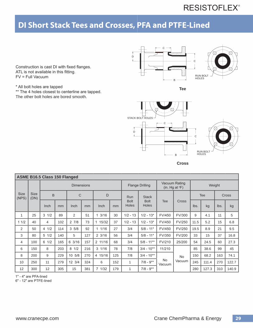
ASME B16.5 Class 150 Flanged
Size(NPS)
Size(DN)
Dimensions Flange Drilling Vacuum Rating(in. Hg at oF) Weight
B C D RunBolt
Holes
StackBolt
HolesTee Cross
Tee Cross
Inch mm Inch mm Inch mm lbs. kg lbs. kg
1 25 3 1/2 89 2 51 1 3/16 30 1/2 - 13 1/2 - 13* FV/450 FV/300 9 4.1 11 5
1 1/2 40 4 102 2 7/8 73 1 15/32 37 1/2 - 13 1/2 - 13* FV/450 FV/250 11.5 5.2 15 6.8
2 50 4 1/2 114 3 5/8 92 1 1/16 27 3/4 5/8 - 11* FV/450 FV/250 19.5 8.9 21 9.5
3 80 5 1/2 140 5 127 2 3/16 56 3/4 5/8 - 11* FV/350 FV/200 33 15 37 16.8
4 100 6 1/2 165 6 3/16 157 2 11/16 68 3/4 5/8 - 11** FV/210 25/200 54 24.5 60 27.3
6 150 8 203 8 1/2 216 3 1/16 78 7/8 3/4 - 10** 11/210
NoVacuum
85 38.6 99 45
8 200 9 229 10 5/8 270 4 15/16 125 7/8 3/4 - 10**No
Vacuum
150 68.2 163 74.1
10 250 11 279 12 3/4 324 6 152 1 7/8 - 9** 245 111.4 270 122.7
12 300 12 305 15 381 7 1/32 179 1 7/8 - 9** 280 127.3 310 140.9
C
D
B
C
STACK BOLT HOLES
RUN BOLT HOLES
C
D
B
C
STACK BOLT HOLES
RUN BOLT HOLES
Tee
Cross
Construction is cast DI with fixed flanges.ATL is not available in this fitting.FV = Full Vacuum
* All bolt holes are tapped** The 4 holes closest to centerline are tapped. The other bolt holes are bored smooth.
DI Short Stack Tees and Crosses, PFA and PTFE-Lined
1" - 4" are PFA-lined6" - 12" are PTFE-lined

30 Crane ChemPharma & Energy www.cranecpe.com
ASME B16.5 Class 150 Flanged - A216 WCB Cast Steel and A395 Cast Ductile Iron
Size(NPS)
Size(DN)
Dimensions
WeightP
J TATL
A216 WCBCast Steel
A395Cast Ductile Iron
Inch mm Inch mm Inch mm lbs. kg
1 x 1 25 x 25 3 1/2 89 3 1/2 89 2 51 2 5/8 67 ● 3.7 1.7
1 1/2 x 1 40 x 25 4 102 4 102 2 7/8 73 3 3/8 86 ● 5.1 2.3
2 x 1 50 x 25 4 1/2 114 5 9/16 141 3 5/8 92 4 1/8 105 ● 6.6 3
3 x 1 80 x 25 5 1/2 140 6 5/16 160 5 127 5 3/8 137 ● 9.2 4.2
4 x 1 100 x 25 6 1/2 165 7 1/16 179 6 3/16 157 6 3/4 171 ● 13.3 6
6 x 1 150 x 25 8 203 8 1/16 205 8 1/2 216 8 3/4 222 ● 17.4 7.9
8 x 1 200 x 25 9 229 9 5/16 237 10 5/8 270 11 279 ● 23.6 10.7
10 x 1 250 x 25 11 279N/A
12 3/4 324 13 3/8 340 ● 38.1 17.3
12 x 1 300 x 25 12 305 15 381 16 1/8 410 ● 50.8 23.1
1" Branch Instrument Tees - Cast Bodies, PTFE-Lined
T400M300ZR110
T400M300ZRB10
T400M300ZR210
T400M300ZR310
T400M300ZR410
2" (51 mm)
Instrument tees are rated for full vacuum to 450 oFA395 Cast Ductile Iron available in 1" - 8", only.A216 WCB Cast Steel and 395 Cast Ductile Iron have the same weight, J and T dimensions, and ATL availability.Weights are approximate
ASME B16.5 Class 300 Flanged
Size(NPS)
Size(DN)
DimensionsWeight
P J TATL
Inch mm Inch mm Inch mm lbs. kg
1 x 1 25 x 25 4 102 2 51 2 7/8 73 ● 4.6 2.1
1 1/2 x 1 40 x 25 4 1/2 114 2 7/8 73 3 3/4 95 ● 6 2.7
2 x 1 50 x 25 5 127 3 5/8 92 4 3/8 111 ● 7.5 3.4
3 x 1 80 x 25 6 152 5 127 5 7/8 149 ● 10.1 4.6
4 x 1 100 x 25 7 178 6 3/16 157 7 1/8 181 ● 14.2 6.5
6 x 1 150 x 25 8 1/2 216 8 1/2 216 9 7/8 251 ● 18.3 8.3
8 x 1 200 x 25 10 254 10 5/8 270 12 1/8 308 ● 24.5 11.1

31www.cranecpe.com Crane ChemPharma & Energy
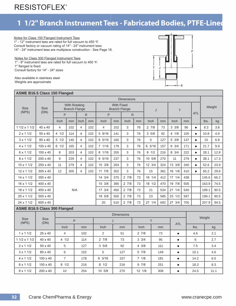
1" Branch Instrument Tees - Fabricated Bodies, PTFE-LinedNotes for Class 150 Flanged Instrument Tees1" - 12" instrument tees are rated for full vacuum to 450 oF. Consult factory or vacuum rating of 14" - 24" instrument tees.14" - 24" instrument tees are multipiece construction - See Page 18.
Notes for Class 300 Flanged Instrument Tees1" - 8" instrument tees are rated for full vacuum to 450 oF. Consult factory for 14" - 24" sizes
Also available in stainless steelWeights are approximate
T400M300ZR110
T400M300ZRB10
T400M300ZR210
T400M300ZR310
T400M300ZR410
2" (51 mm) ASME B16.5 Class 150 Flanged
Size(NPS)
Size(DN)
Dimensions
WeightPJ T
ATLWith RotatingBranch Flange
With FixedBranch Flange
Inch mm Inch mm Inch mm Inch mm lbs. kg
1 x 1 25 x 25 3 1/2 89 3 1/2 89 2 51 2 5/8 67 ● 3.7 1.7
1 1/2 x 1 40 x 25 4 102 4 102 2 7/8 73 3 3/8 86 ● 5.1 2.3
2 x 1 50 x 25 4 1/2 114 5 9/16 141 3 5/8 92 4 1/8 105 ● 6.6 3
3 x 1 80 x 25 5 1/2 140 6 5/16 160 5 127 5 3/8 137 ● 9.2 4.2
4 x 1 100 x 25 6 1/2 165 7 1/16 179 6 3/16 157 6 3/4 171 ● 13.3 6
6 x 1 150 x 25 8 203 8 1/16 205 8 1/2 216 8 3/4 222 ● 17.4 7.9
8 x 1 200 x 25 9 229 9 5/16 237 10 5/8 270 11 279 ● 23.6 10.7
10 x 1 250 x 25 11 279 10 3/8 264 12 3/4 324 13 3/8 340 ● 38.1 17.3
12 x 1 300 x 25 12 305 11 7/8 302 15 381 16 1/8 410 ● 50.8 23.1
14 x 1 350 x 25
N/A
14 3/4 375 16 1/4 412 17 1/4 438 116.8 53.1
16 x 1 400 x 25 15 3/8 390 18 1/2 470 19 7/8 505 130 59.1
18 x 1 450 x 25 17 3/4 450 21 534 21 1/4 540 150.7 68.5
20 x 1 500 x 25 19 5/8 500 23 585 23 1/2 597 158.6 72.1
24 x 1 600 x 25 20 510 27 1/4 692 27 3/4 705 174 79.1
ASME B16.5 Class 300 Flanged
Size(NPS)
Size(DN)
Dimensions
WeightPJ T
ATLWith RotatingBranch Flange
With FixedBranch Flange
Inch mm Inch mm Inch mm Inch mm lbs. kg
1 x 1 25 x 25 4 102 4 102 2 51 2 7/8 73 ● 4.6 2.1
1 1/2 x 1 40 x 25 4 1/2 114 4 1/2 114 2 7/8 73 3 3/4 95 ● 6 2.7
2 x 1 50 x 25 5 127 5 9/16 141 3 5/8 92 4 3/8 111 ● 7.5 3.4
3 x 1 80 x 25 6 152 6 5/16 160 5 127 5 7/8 149 ● 10.1 4.6
4 x 1 100 x 25 7 178 7 1/16 179 6 3/16 157 7 1/8 181 ● 14.2 6.5
6 x 1 150 x 25 8 1/2 216 8 1/16 205 8 1/2 216 9 7/8 251 ● 18.3 8.3
8 x 1 200 x 25 10 254 9 5/16 235 10 5/8 270 12 1/8 308 ● 24.5 11.1
Note: 1" - 8" Instrument tees can be supplied with two branches, 180 degrees apart, on request.
32 Crane ChemPharma & Energy www.cranecpe.com
Instrument Tee with 1.5" Branch PTFE-Lined Housing Materials FAB STEEL = Housing fabricated from pipe and/or weld fittings DI = ASTM A395 Cast Ductile Iron
Flange Materials CS = ASTM A105 DI = ASTM A395 Cast Ductile Iron
FV = Full Vacuum
*Nominal ID. For exact ID to determine if an instrument will fit in the bore, field measurement is necessary.
e z i S ) S P N ( s r e b m u N t r a P
) . n i ( s n o i s n e m i D g n i s u o H l a i r e t a M
s e g n a l F g n i t a R m u u c a V
) F / g H . n i ( P R T J * S l a i r e t a M g n i t a t o R = R d e x i F = F
5 . 1 0 B B S Z 0 0 3 M 0 0 4 T
4 3
8 / 3 3 8 / 7 2 6 1 / 5 1
L E E T S B A F S C
F
0 5 4 / V F
0 B B R Z 0 0 3 M 0 0 4 T 4 8 / 1 1 R
2 0 B 2 S Z 0 0 3 M 0 0 4 T 6 1 / 9 5 3
8 / 1 4 8 / 5 3 6 1 / 5 1 F
0 B 2 R Z 0 0 3 M 0 0 4 T 2 / 1 4 4 8 / 1 1 R
3 0 B 3 N V 0 0 1 M 0 0 4 T 6 1 / 5 6 3
8 / 3 5 5 6 1 / 5 1 I D I D F
0 B 3 R Z 0 0 3 M 0 0 4 T 2 / 1 5 4 8 / 1 1
L E E T S B A F S C
R
4 0 B 4 S Z 0 0 3 M 0 0 4 T 6 1 / 1 7 3
8 / 7 6 6 1 / 3 6 6 1 / 5 1 F
0 B 4 R Z 0 0 3 M 0 0 4 T 2 / 1 6 4 8 / 1 1 R
6 0 B 6 S Z 0 0 3 M 0 0 4 T 6 1 / 1 8 3
4 / 3 8 2 / 1 8 6 1 / 5 1 F 0 5 4 / V F
0 B 6 R Z 0 0 3 M 0 0 4 T 8 4 8 / 1 1 R 0 0 4 / 7 2
8 0 B 8 S Z 0 0 3 M 0 0 4 T 6 1 / 5 9 3
1 1 8 / 5 0 1 6 1 / 5 1 F 0 5 4 / V F
0 B 8 R Z 0 0 3 M 0 0 4 T 9 4 8 / 1 1 R m u u c a V o N
0 1 0 B E S Z 0 0 3 M 0 0 4 T 8 / 3 0 1 3 8 / 3 3 1
4 / 3 2 1 6 1 / 5 1 F 0 5 4 / V F
0 B E R Z 0 0 3 B 0 0 4 T 1 1 4 4 / 1 3 1 8 / 1 1 R m u u c a V o N
2 1 0 B F S Z 0 0 3 M 0 0 4 T 8 / 7 1 1 3 8 / 1 6 1
5 1 6 1 / 5 1 F 0 5 4 / V F
0 B F R Z 0 0 3 B 0 0 4 T 2 1 4 6 1 8 / 1 1 R m u u c a V o N
e z i S ) S P N ( s r e b m u N t r a P
) . n i ( s n o i s n e m i D g n i s u o H l a i r e t a M
s e g n a l F g n i t a R m u u c a V
) F / g H . n i ( P R T J * S l a i r e t a M g n i t a t o R = R d e x i F = F
5 . 1 0 B B S Y 0 0 A M 0 0 4 / 3 T 4 1/2 3
3 2
4 3 8 / 7 2 2 3 / 1 1 1
L E E T S B A F S C F 0 5 4 / V F
3 0 B 3 S Y 0 0 A M 0 0 4 T 6 1 / 5 6 3 8 / 7 5 5 2 3 / 1 1 1
4 0 B 4 S Y 0 0 A M 0 0 4 T 6 1 / 1 7 3 8 / 1 7 6 1 / 3 6 2 3 / 1 1 1
6 0 B 6 S Y 0 0 A M 0 0 4 T 6 1 / 1 9 7/8
12 1/8
/ 1 8 2 3 / 1 1 1
8 0 B 8 S Y 0 0 A M 0 0 4 T 6 1 / 5 / 5 0 1 2 3 / 1 1 1
150lb. Flanged
300lb. Flanged
8 8 3 9
ASME B16.5 Class 150 Flanged
Size(NPS)
Size(DN)
Dimensions
WeightWith RotatingBranch Flange
With FixedBranch Flange J T
ATLP R P R
Inch mm Inch mm Inch mm Inch mm Inch mm Inch mm lbs. kg
1 1/2 x 1 1/2 40 x 40 4 102 4 102 4 102 3 76 2 7/8 73 3 3/8 86 ● 8.3 3.8
2 x 1 1/2 50 x 40 4 1/2 114 4 102 5 9/16 141 3 76 3 5/8 92 4 1/8 105 ● 10.8 4.9
3 x 1 1/2 80 x 40 5 1/2 140 4 102 6 5/16 160 3 76 5 127 5 3/8 137 ● 15 6.8
4 x 1 1/2 100 x 40 6 1/2 165 4 102 7 1/16 179 3 76 6 3/16 157 6 3/4 171 ● 21.7 9.9
6 x 1 1/2 150 x 40 8 203 4 102 8 1/16 205 3 76 8 1/2 216 8 3/4 222 ● 28.1 12.8
8 x 1 1/2 200 x 40 9 229 4 102 9 5/16 237 3 76 10 5/8 270 11 279 ● 38.1 17.3
10 x 1 1/2 250 x 40 11 279 4 102 10 3/8 264 3 76 12 3/4 324 13 3/8 340 ● 52.6 23.9
12 x 1 1/2 300 x 40 12 305 4 102 11 7/8 302 3 76 15 381 16 1/8 410 ● 65.2 29.6
14 x 1 1/2 350 x 40
N/A
14 3/4 375 2 7/8 73 16 1/4 412 17 1/4 438 145.6 66.2
16 x 1 1/2 400 x 40 15 3/8 390 2 7/8 73 18 1/2 470 19 7/8 505 163.9 74.5
18 x 1 1/2 450 x 40 17 3/4 450 2 7/8 73 21 534 21 1/4 540 199.1 90.5
20 x 1 1/2 500 x 40 19 5/8 500 2 7/8 73 23 585 23 1/2 597 199.1 90.5
24 x 1 1/2 600 x 40 20 510 2 7/8 73 27 1/4 692 27 3/4 705 207.9 94.5
1 1/2" Branch Instrument Tees - Fabricated Bodies, PTFE-Lined
ASME B16.5 Class 300 Flanged
Size(NPS)
Size(DN)
DimensionsWeight
P J TATL
Inch mm Inch mm Inch mm lbs. kg
1 x 1 1/2 25 x 40 4 102 2 51 2 7/8 73 ● 4.6 2.1
1 1/2 x 1 1/2 40 x 40 4 1/2 114 2 7/8 73 3 3/4 95 ● 6 2.7
2 x 1 1/2 50 x 40 5 127 3 5/8 92 4 3/8 111 ● 7.5 3.4
3 x 1 1/2 80 x 40 6 152 5 127 5 7/8 149 ● 10.1 4.6
4 x 1 1/2 100 x 40 7 178 6 3/16 157 7 1/8 181 ● 14.2 6.5
6 x 1 1/2 150 x 40 8 1/2 216 8 1/2 216 9 7/8 251 ● 18.3 8.3
8 x 1 1/2 200 x 40 10 254 10 5/8 270 12 1/8 308 ● 24.5 11.1
Notes for Class 150 Flanged Instrument Tees1" - 12" instrument tees are rated for full vacuum to 450 oF. Consult factory or vacuum rating of 14" - 24" instrument tees.14" - 24" instrument tees are multipiece construction - See Page 18.
Notes for Class 300 Flanged Instrument Tees1" - 8" instrument tees are rated for full vacuum to 450 oF. 1" flanged is fixed.Consult factory for 14" - 24" sizes
Also available in stainless steelWeights are approximate
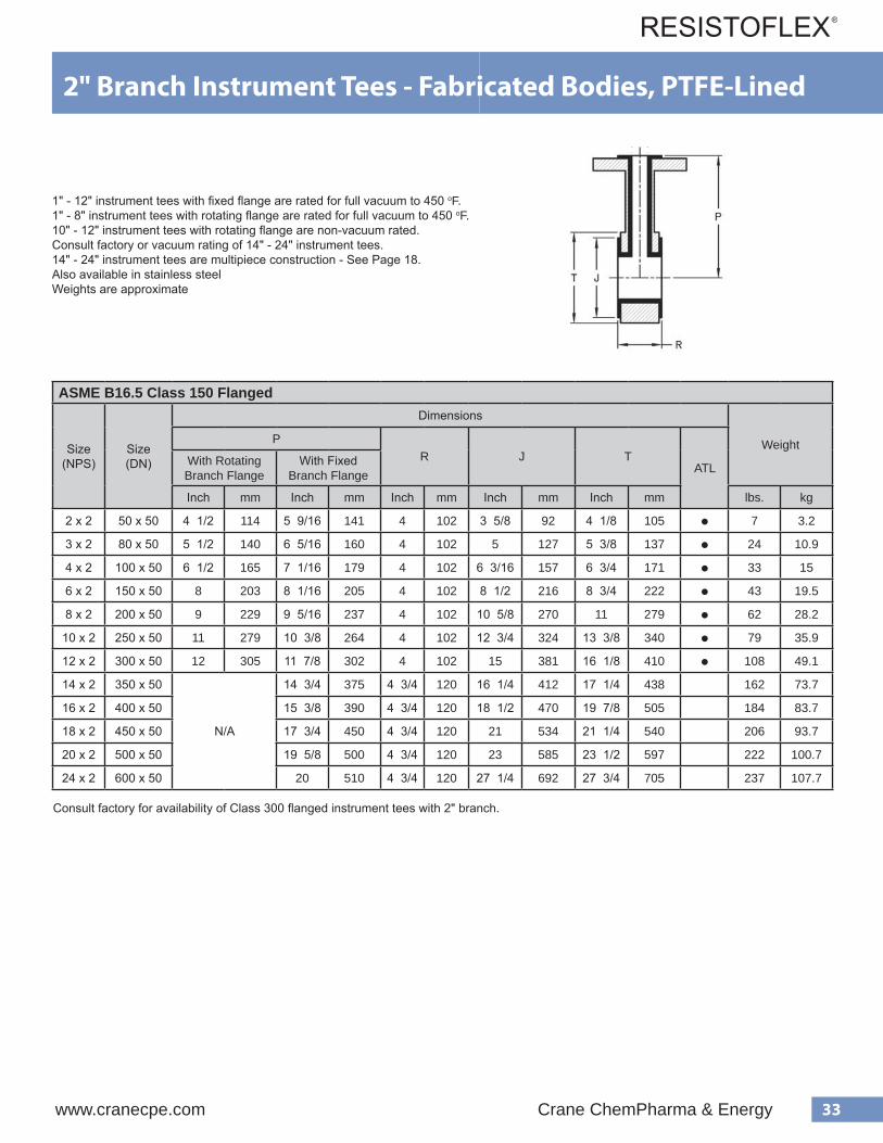
33www.cranecpe.com Crane ChemPharma & Energy
2" Branch Instrument Tees - Fabricated Bodies, PTFE-Lined
ASME B16.5 Class 150 Flanged
Size(NPS)
Size(DN)
Dimensions
WeightPR J T
ATLWith RotatingBranch Flange
With FixedBranch Flange
Inch mm Inch mm Inch mm Inch mm Inch mm lbs. kg
2 x 2 50 x 50 4 1/2 114 5 9/16 141 4 102 3 5/8 92 4 1/8 105 ● 7 3.2
3 x 2 80 x 50 5 1/2 140 6 5/16 160 4 102 5 127 5 3/8 137 ● 24 10.9
4 x 2 100 x 50 6 1/2 165 7 1/16 179 4 102 6 3/16 157 6 3/4 171 ● 33 15
6 x 2 150 x 50 8 203 8 1/16 205 4 102 8 1/2 216 8 3/4 222 ● 43 19.5
8 x 2 200 x 50 9 229 9 5/16 237 4 102 10 5/8 270 11 279 ● 62 28.2
10 x 2 250 x 50 11 279 10 3/8 264 4 102 12 3/4 324 13 3/8 340 ● 79 35.9
12 x 2 300 x 50 12 305 11 7/8 302 4 102 15 381 16 1/8 410 ● 108 49.1
14 x 2 350 x 50
N/A
14 3/4 375 4 3/4 120 16 1/4 412 17 1/4 438 162 73.7
16 x 2 400 x 50 15 3/8 390 4 3/4 120 18 1/2 470 19 7/8 505 184 83.7
18 x 2 450 x 50 17 3/4 450 4 3/4 120 21 534 21 1/4 540 206 93.7
20 x 2 500 x 50 19 5/8 500 4 3/4 120 23 585 23 1/2 597 222 100.7
24 x 2 600 x 50 20 510 4 3/4 120 27 1/4 692 27 3/4 705 237 107.7
Instrument Tee with 1.5" Branch PTFE-Lined Housing Materials FAB STEEL = Housing fabricated from pipe and/or weld fittings DI = ASTM A395 Cast Ductile Iron
Flange Materials CS = ASTM A105 DI = ASTM A395 Cast Ductile Iron
FV = Full Vacuum
*Nominal ID. For exact ID to determine if an instrument will fit in the bore, field measurement is necessary.
e z i S ) S P N ( s r e b m u N t r a P
) . n i ( s n o i s n e m i D g n i s u o H l a i r e t a M
s e g n a l F g n i t a R m u u c a V
) F / g H . n i ( P R T J * S l a i r e t a M g n i t a t o R = R d e x i F = F
5 . 1 0 B B S Z 0 0 3 M 0 0 4 T
4 3
8 / 3 3 8 / 7 2 6 1 / 5 1
L E E T S B A F S C
F
0 5 4 / V F
0 B B R Z 0 0 3 M 0 0 4 T 4 8 / 1 1 R
2 0 B 2 S Z 0 0 3 M 0 0 4 T 6 1 / 9 5 3
8 / 1 4 8 / 5 3 6 1 / 5 1 F
0 B 2 R Z 0 0 3 M 0 0 4 T 2 / 1 4 4 8 / 1 1 R
3 0 B 3 N V 0 0 1 M 0 0 4 T 6 1 / 5 6 3
8 / 3 5 5 6 1 / 5 1 I D I D F
0 B 3 R Z 0 0 3 M 0 0 4 T 2 / 1 5 4 8 / 1 1
L E E T S B A F S C
R
4 0 B 4 S Z 0 0 3 M 0 0 4 T 6 1 / 1 7 3
8 / 7 6 6 1 / 3 6 6 1 / 5 1 F
0 B 4 R Z 0 0 3 M 0 0 4 T 2 / 1 6 4 8 / 1 1 R
6 0 B 6 S Z 0 0 3 M 0 0 4 T 6 1 / 1 8 3
4 / 3 8 2 / 1 8 6 1 / 5 1 F 0 5 4 / V F
0 B 6 R Z 0 0 3 M 0 0 4 T 8 4 8 / 1 1 R 0 0 4 / 7 2
8 0 B 8 S Z 0 0 3 M 0 0 4 T 6 1 / 5 9 3
1 1 8 / 5 0 1 6 1 / 5 1 F 0 5 4 / V F
0 B 8 R Z 0 0 3 M 0 0 4 T 9 4 8 / 1 1 R m u u c a V o N
0 1 0 B E S Z 0 0 3 M 0 0 4 T 8 / 3 0 1 3 8 / 3 3 1
4 / 3 2 1 6 1 / 5 1 F 0 5 4 / V F
0 B E R Z 0 0 3 B 0 0 4 T 1 1 4 4 / 1 3 1 8 / 1 1 R m u u c a V o N
2 1 0 B F S Z 0 0 3 M 0 0 4 T 8 / 7 1 1 3 8 / 1 6 1
5 1 6 1 / 5 1 F 0 5 4 / V F
0 B F R Z 0 0 3 B 0 0 4 T 2 1 4 6 1 8 / 1 1 R m u u c a V o N
e z i S ) S P N ( s r e b m u N t r a P
) . n i ( s n o i s n e m i D g n i s u o H l a i r e t a M
s e g n a l F g n i t a R m u u c a V
) F / g H . n i ( P R T J * S l a i r e t a M g n i t a t o R = R d e x i F = F
5 . 1 0 B B S Y 0 0 A M 0 0 4 / 3 T 4 1/2 3
3 2
4 3 8 / 7 2 2 3 / 1 1 1
L E E T S B A F S C F 0 5 4 / V F
3 0 B 3 S Y 0 0 A M 0 0 4 T 6 1 / 5 6 3 8 / 7 5 5 2 3 / 1 1 1
4 0 B 4 S Y 0 0 A M 0 0 4 T 6 1 / 1 7 3 8 / 1 7 6 1 / 3 6 2 3 / 1 1 1
6 0 B 6 S Y 0 0 A M 0 0 4 T 6 1 / 1 9 7/8
12 1/8
/ 1 8 2 3 / 1 1 1
8 0 B 8 S Y 0 0 A M 0 0 4 T 6 1 / 5 / 5 0 1 2 3 / 1 1 1
150lb. Flanged
300lb. Flanged
8 8 3 9
1" - 12" instrument tees with fixed flange are rated for full vacuum to 450 oF. 1" - 8" instrument tees with rotating flange are rated for full vacuum to 450 oF.10" - 12" instrument tees with rotating flange are non-vacuum rated.Consult factory or vacuum rating of 14" - 24" instrument tees.14" - 24" instrument tees are multipiece construction - See Page 18.Also available in stainless steelWeights are approximate
Consult factory for availability of Class 300 flanged instrument tees with 2" branch.
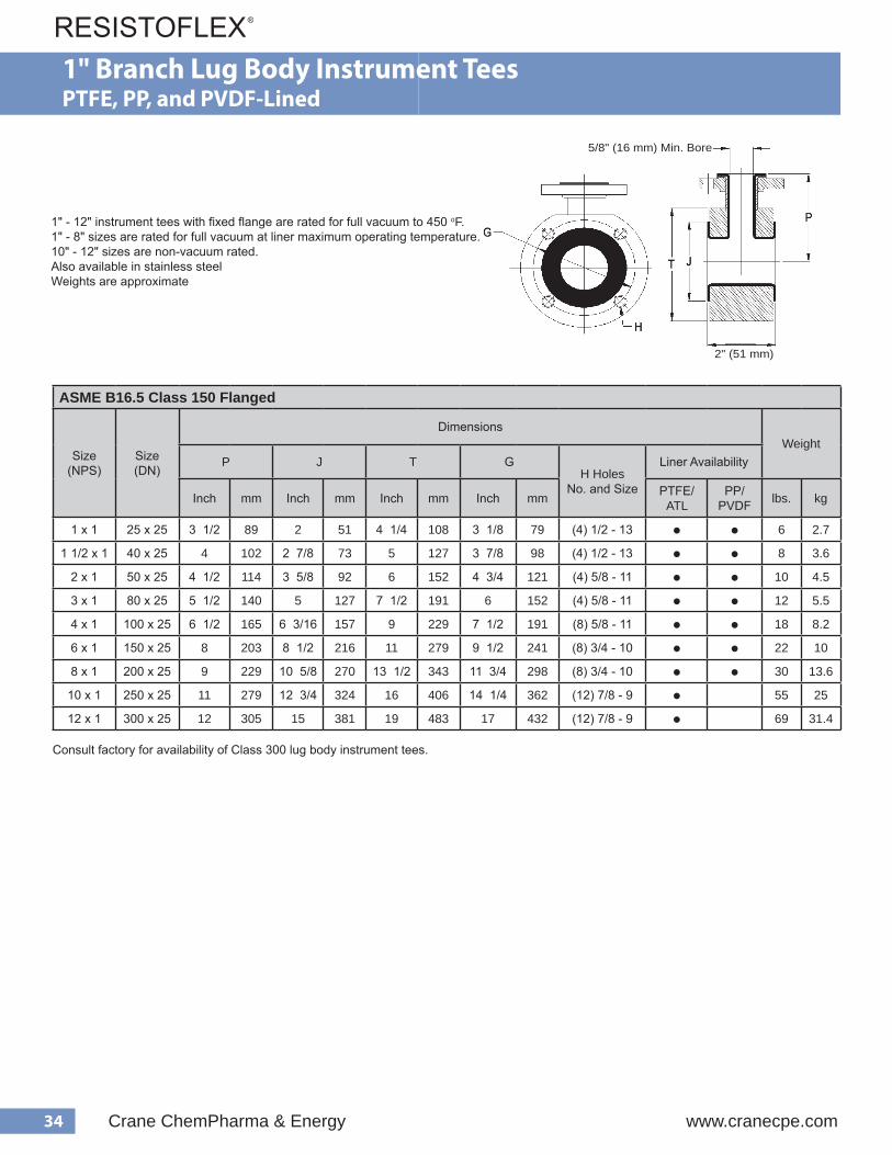
34 Crane ChemPharma & Energy www.cranecpe.com
ASME B16.5 Class 150 Flanged
Size(NPS)
Size(DN)
DimensionsWeight
P J T GH Holes
No. and Size
Liner Availability
Inch mm Inch mm Inch mm Inch mm PTFE/ATL
PP/PVDF lbs. kg
1 x 1 25 x 25 3 1/2 89 2 51 4 1/4 108 3 1/8 79 (4) 1/2 - 13 ● ● 6 2.7
1 1/2 x 1 40 x 25 4 102 2 7/8 73 5 127 3 7/8 98 (4) 1/2 - 13 ● ● 8 3.6
2 x 1 50 x 25 4 1/2 114 3 5/8 92 6 152 4 3/4 121 (4) 5/8 - 11 ● ● 10 4.5
3 x 1 80 x 25 5 1/2 140 5 127 7 1/2 191 6 152 (4) 5/8 - 11 ● ● 12 5.5
4 x 1 100 x 25 6 1/2 165 6 3/16 157 9 229 7 1/2 191 (8) 5/8 - 11 ● ● 18 8.2
6 x 1 150 x 25 8 203 8 1/2 216 11 279 9 1/2 241 (8) 3/4 - 10 ● ● 22 10
8 x 1 200 x 25 9 229 10 5/8 270 13 1/2 343 11 3/4 298 (8) 3/4 - 10 ● ● 30 13.6
10 x 1 250 x 25 11 279 12 3/4 324 16 406 14 1/4 362 (12) 7/8 - 9 ● 55 25
12 x 1 300 x 25 12 305 15 381 19 483 17 432 (12) 7/8 - 9 ● 69 31.4
26
Lugged Body Instrument Tees, 1" Branch PTFE / Polypropylene / PVDF-Lined, 150lb. Flanged Housing Materials Fabricated Steel
Flange Material ASTM A105 Forged Steel
V acuum Ratings All 1” - 8” lugged body instrument tees are rated for full vacuum at maximum operating temperature. 10” - 12” sizes are not rated for vacuum service.
Actual branch inside diameter may vary. If ID of branch is critical, consult the factory.
Note: Lugged Body Instrument Tees cannot be installed side by side, they need to have a flanged spool installed between them.
PTFE lined lugged body instrument tees are supplied with a rotating flange on the branch. PP & PVDF lined lugged body instrument tees are supplied with a fixed flange on the branch.
e z i S ) S P N ( r e n i L s r e b m u N t r a P
) . n i ( s n o i s n e m i D
P T J s e l o H H e z i S & . o N G
1
E F T P 0 1 1 L Z Z Z 3 M 0 0 4 T
2 / 1 3 4 / 1 4 2 3 1 - 2 / 1 ) 4 ( 8 / 1 3 P P 0 1 1 L Z Z Z 3 P 0 0 4 T
F D V P 0 1 1 L Z Z Z 3 K 0 0 4 T
2 / 1 1
E F T P 0 1 B L Z Z Z 3 M 0 0 4 T
4 5 8 / 7 2 3 1 - 2 / 1 ) 4 ( 8 / 7 3 P P 0 1 B L Z Z Z 3 P 0 0 4 T
F D V P 0 1 B L Z Z Z 3 K 0 0 4 T
2
E F T P 0 1 2 L Z Z Z 3 M 0 0 4 T
2 / 1 4 6 8 / 5 3 1 1 - 8 / 5 ) 4 ( 4 / 3 4 P P 0 1 2 L Z Z Z 3 P 0 0 4 T
F D V P 0 1 2 L Z Z Z 3 K 0 0 4 T
3
E F T P 0 1 3 L Z Z Z 3 M 0 0 4 T
2 / 1 5 2 / 1 7 5 1 1 - 8 / 5 ) 4 ( 6 P P 0 1 3 L Z Z Z 3 P 0 0 4 T
F D V P 0 1 3 L Z Z Z 3 K 0 0 4 T
4
E F T P 0 1 4 L Z Z Z 3 M 0 0 4 T
2 / 1 6 9 6 1 / 3 6 1 1 - 8 / 5 ) 8 ( 2 / 1 7 P P 0 1 4 L Z Z Z 3 P 0 0 4 T
F D V P 0 1 4 L Z Z Z 3 K 0 0 4 T
6
E F T P 0 1 6 L Z Z Z 3 M 0 0 4 T
8 1 1 2 / 1 8 0 1 - 4 / 3 ) 8 ( 2 / 1 9 P P 0 1 6 L Z Z Z 3 P 0 0 4 T
F D V P 0 1 6 L Z Z Z 3 K 0 0 4 T
8
E F T P 0 1 8 L Z Z Z 3 M 0 0 4 T
9 2 / 1 3 1 8 / 5 0 1 0 1 - 4 / 3 ) 8 ( 4 / 3 1 1 P P 0 1 8 L Z Z Z 3 P 0 0 4 T
F D V P 0 1 8 L Z Z Z 3 K 0 0 4 T
0 1 E F T P 0 1 E L Z Z Z 3 B 0 0 4 T 1 1 6 1 4 / 3 2 1 9 - 8 / 7 ) 2 1 ( 4 / 1 4 1
2 1 E F T P 0 1 F L Z Z Z 3 B 0 0 4 T 2 1 9 1 5 1 9 - 8 / 7 ) 2 1 ( 7 1
2" (51 mm)
5/8" (16 mm) Min. Bore
1" - 12" instrument tees with fixed flange are rated for full vacuum to 450 oF. 1" - 8" sizes are rated for full vacuum at liner maximum operating temperature.10" - 12" sizes are non-vacuum rated.Also available in stainless steelWeights are approximate
1" Branch Lug Body Instrument TeesPTFE, PP, and PVDF-Lined
Consult factory for availability of Class 300 lug body instrument tees.
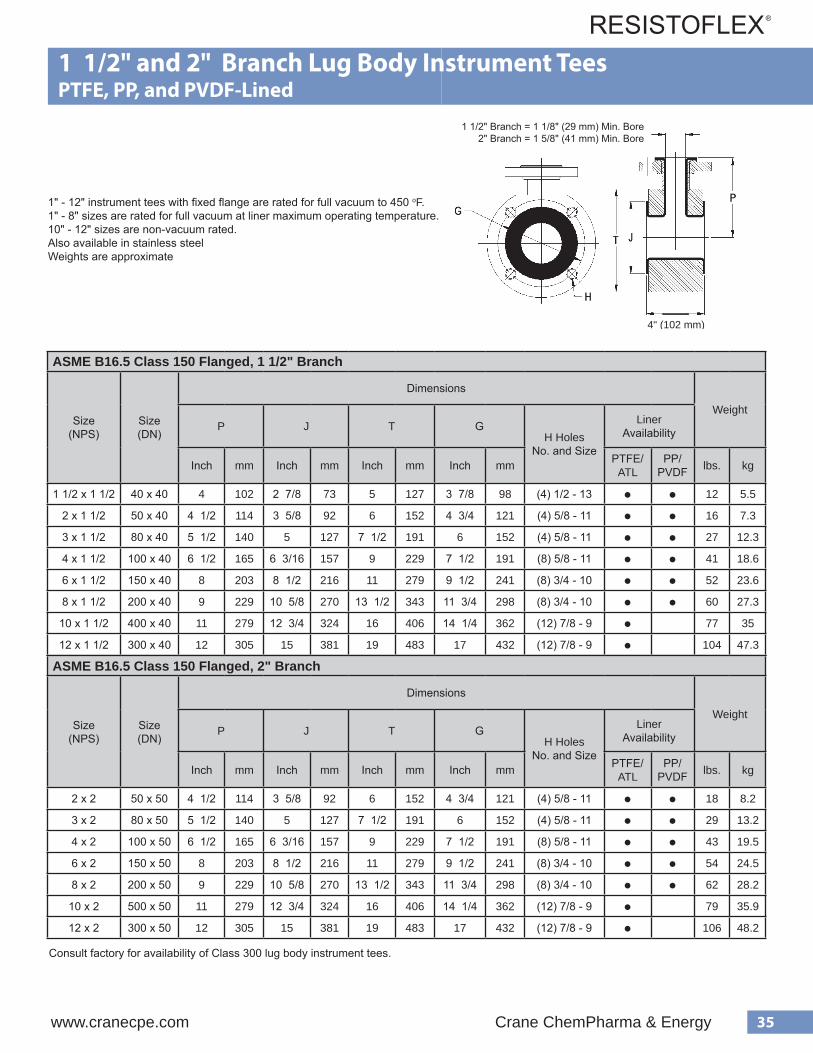
35www.cranecpe.com Crane ChemPharma & Energy
27
Lugged Body Instrument Tees, 1.5” Branch PTFE / Polypropylene / PVDF-Lined, 150lb. Flanged Housing Materials Fabricated Steel
Flange Material ASTM A105 Forged Steel
V acuum Ratings All 1 1/2” - 8” lugged body instrument tees are rated for full vacuum at maximum operating temperature. 10” - 12” sizes are not rated for vacuum service.
Actual branch inside diameter may vary. If ID of branch is critical, consult the factory.
Note: Lugged Body Instrument Tees cannot be installed side by side, they need to have a flanged spool installed between them.
PTFE lined lugged body instrument tees are supplied with a rotating flange on the branch. PP & PVDF lined lugged body instrument tees are supplied with a fixed flange on the branch.
e z i S ) S P N ( r e n i L s r e b m u N t r a P
) . n i ( s n o i s n e m i D
P T J s e l o H H e z i S & . o N G
2 / 1 1
E F T P 0 B B L Z Z Z 3 M 0 0 4 T
4 5 8 / 7 2 3 1 - 2 / 1 ) 4 ( 8 / 7 3 P P 0 B B L Z Z Z 3 P 0 0 4 T
F D V P 0 B B L Z Z Z 3 K 0 0 4 T
2
E F T P 0 B 2 L Z Z Z 3 M 0 0 4 T
2 / 1 4 6 8 / 5 3 1 1 - 8 / 5 ) 4 ( 4 / 3 4 P P 0 B 2 L Z Z Z 3 P 0 0 4 T
F D V P 0 B 2 L Z Z Z 3 K 0 0 4 T
3
E F T P 0 B 3 L Z Z Z 3 M 0 0 4 T
2 / 1 5 2 / 1 7 5 1 1 - 8 / 5 ) 4 ( 6 P P 0 B 3 L Z Z Z 3 P 0 0 4 T
F D V P 0 B 3 L Z Z Z 3 K 0 0 4 T
4
E F T P 0 B 4 L Z Z Z 3 M 0 0 4 T
2 / 1 6 9 6 1 / 3 6 1 1 - 8 / 5 ) 8 ( 2 / 1 7 P P 0 B 4 L Z Z Z 3 P 0 0 4 T
F D V P 0 B 4 L Z Z Z 3 K 0 0 4 T
6
E F T P 0 B 6 L Z Z Z 3 M 0 0 4 T
8 1 1 2 / 1 8 0 1 - 4 / 3 ) 8 ( 2 / 1 9 P P 0 B 6 L Z Z Z 3 P 0 0 4 T
F D V P 0 B 6 L Z Z Z 3 K 0 0 4 T
8
E F T P 0 B 8 L Z Z Z 3 M 0 0 4 T
9 2 / 1 3 1 8 / 5 0 1 0 1 - 4 / 3 ) 8 ( 4 / 3 1 1 P P 0 B 8 L Z Z Z 3 P 0 0 4 T
F D V P 0 B 8 L Z Z Z 3 K 0 0 4 T
0 1 E F T P 0 B E L Z Z Z 3 B 0 0 4 T 1 1 6 1 4 / 3 2 1 9 - 8 / 7 ) 2 1 ( 4 / 1 4 1
2 1 E F T P 0 B F L Z Z Z 3 B 0 0 4 T 2 1 9 1 5 1 9 - 8 / 7 ) 2 1 ( 7 1
4" (102 mm)
1" - 12" instrument tees with fixed flange are rated for full vacuum to 450 oF. 1" - 8" sizes are rated for full vacuum at liner maximum operating temperature.10" - 12" sizes are non-vacuum rated.Also available in stainless steelWeights are approximate
ASME B16.5 Class 150 Flanged, 1 1/2" Branch
Size(NPS)
Size(DN)
Dimensions
WeightP J T G
H HolesNo. and Size
Liner Availability
Inch mm Inch mm Inch mm Inch mm PTFE/ATL
PP/PVDF lbs. kg
1 1/2 x 1 1/2 40 x 40 4 102 2 7/8 73 5 127 3 7/8 98 (4) 1/2 - 13 ● ● 12 5.5
2 x 1 1/2 50 x 40 4 1/2 114 3 5/8 92 6 152 4 3/4 121 (4) 5/8 - 11 ● ● 16 7.3
3 x 1 1/2 80 x 40 5 1/2 140 5 127 7 1/2 191 6 152 (4) 5/8 - 11 ● ● 27 12.3
4 x 1 1/2 100 x 40 6 1/2 165 6 3/16 157 9 229 7 1/2 191 (8) 5/8 - 11 ● ● 41 18.6
6 x 1 1/2 150 x 40 8 203 8 1/2 216 11 279 9 1/2 241 (8) 3/4 - 10 ● ● 52 23.6
8 x 1 1/2 200 x 40 9 229 10 5/8 270 13 1/2 343 11 3/4 298 (8) 3/4 - 10 ● ● 60 27.3
10 x 1 1/2 400 x 40 11 279 12 3/4 324 16 406 14 1/4 362 (12) 7/8 - 9 ● 77 35
12 x 1 1/2 300 x 40 12 305 15 381 19 483 17 432 (12) 7/8 - 9 ● 104 47.3
1 1/2" and 2" Branch Lug Body Instrument TeesPTFE, PP, and PVDF-Lined
ASME B16.5 Class 150 Flanged, 2" Branch
Size(NPS)
Size(DN)
Dimensions
WeightP J T G
H HolesNo. and Size
Liner Availability
Inch mm Inch mm Inch mm Inch mm PTFE/ATL
PP/PVDF lbs. kg
2 x 2 50 x 50 4 1/2 114 3 5/8 92 6 152 4 3/4 121 (4) 5/8 - 11 ● ● 18 8.2
3 x 2 80 x 50 5 1/2 140 5 127 7 1/2 191 6 152 (4) 5/8 - 11 ● ● 29 13.2
4 x 2 100 x 50 6 1/2 165 6 3/16 157 9 229 7 1/2 191 (8) 5/8 - 11 ● ● 43 19.5
6 x 2 150 x 50 8 203 8 1/2 216 11 279 9 1/2 241 (8) 3/4 - 10 ● ● 54 24.5
8 x 2 200 x 50 9 229 10 5/8 270 13 1/2 343 11 3/4 298 (8) 3/4 - 10 ● ● 62 28.2
10 x 2 500 x 50 11 279 12 3/4 324 16 406 14 1/4 362 (12) 7/8 - 9 ● 79 35.9
12 x 2 300 x 50 12 305 15 381 19 483 17 432 (12) 7/8 - 9 ● 106 48.2
1 1/2" Branch = 1 1/8" (29 mm) Min. Bore 2" Branch = 1 5/8" (41 mm) Min. Bore
Consult factory for availability of Class 300 lug body instrument tees.
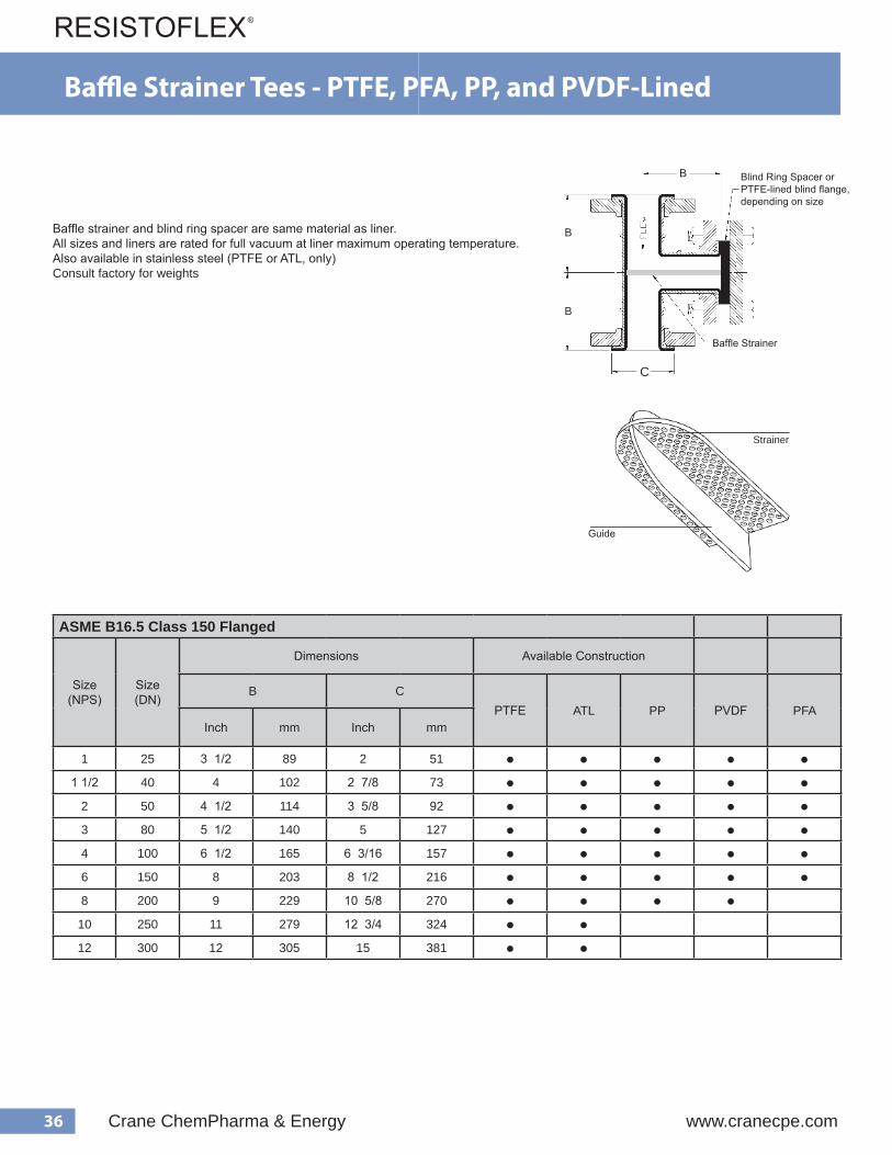
36 Crane ChemPharma & Energy www.cranecpe.com
Ba�e Strainer Tees - PTFE, PFA, PP, and PVDF-Lined
ASME B16.5 Class 150 Flanged
Size(NPS)
Size(DN)
Dimensions Available Construction
B CPTFE ATL PP PVDF PFA
Inch mm Inch mm
1 25 3 1/2 89 2 51 ● ● ● ● ●1 1/2 40 4 102 2 7/8 73 ● ● ● ● ●
2 50 4 1/2 114 3 5/8 92 ● ● ● ● ●3 80 5 1/2 140 5 127 ● ● ● ● ●4 100 6 1/2 165 6 3/16 157 ● ● ● ● ●6 150 8 203 8 1/2 216 ● ● ● ● ●8 200 9 229 10 5/8 270 ● ● ● ●
10 250 11 279 12 3/4 324 ● ●12 300 12 305 15 381 ● ●
Strainer Tee AssemblyPTFE-Lined, 150lb. FlangedHousing MaterialFAB STEEL = Housing fabricated from carbon steel pipe and/or weld fittings.
Flange MaterialCS = ASTM A105DI = ASTM A395 Cast Ductile Iron
FV = Full Vacuum
Note: 12th character in the part number indicates the size of the holes in the strainer.All part numbers in the table are shown with an “R”, which indicates 1/8” holes. Thefollowing are the available hole sizes and theircorresponding character: Q = 1/16”; R = 1/8”; S = 3/16”; T = 1/4”; U = 5/16”; V = 3/8”
If other hole sizes are required, please contact the factory.
B
B
B
C
eziS)SPN( rebmuNtraP
).ni(snoisnemiDgnisuoHlairetaM
segnalF gnitaRmuucaV)F/gH.ni(
B C lairetaM gnitatoR=RdexiF=F
10R1VVVV3M708T
2/13 2
LEETSBAF
ID
R
0R1VZZZ3M708T SC
2/110RBVVVV3M708T
4 8/72ID
0RBVZZZ3M708T SC
20R2VVVV3M708T
2/14 8/53ID
0R2VZZZ3M708T SC
30R3VVVV3M708T
2/15 5ID
0R3VZZZ3M708T SC054/VF
40R4VVVV3M708T
2/16 61/36ID
0R4VZZZ3M708T SC
60R6VVVV3M708T
8 2/180R6VZZZ3M708T
T
ID
SC
ID
SC
ID
SC
ID
SC
R8VVVV3M708
10REVVVV3M708
12RFVVVV3M708
573/VF
T807M3ZZZV8R0
T807M3ZZZVER0
T807M3ZZZVFR0
80
0
0
T
T
9 10 5/8
12 3/4
15
11
12
Blind Ring Spacer or PTFE-lined blind flange, depending on size
Baffle Strainer
Strainer
Guide
Baffle strainer and blind ring spacer are same material as liner.All sizes and liners are rated for full vacuum at liner maximum operating temperature.Also available in stainless steel (PTFE or ATL, only)Consult factory for weights
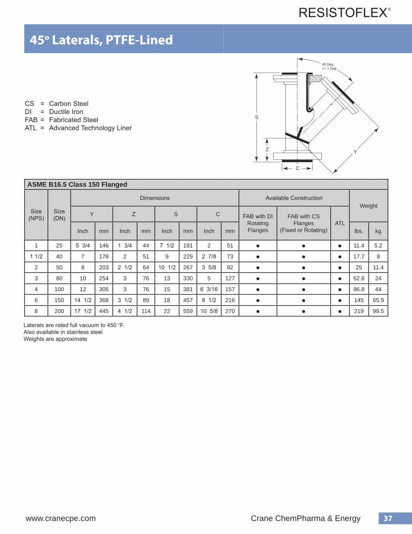
37www.cranecpe.com Crane ChemPharma & Energy
Ba�e Strainer Tees - PTFE, PFA, PP, and PVDF-Lined
CS = Carbon SteelDI = Ductile IronFAB = Fabricated SteelATL = Advanced Technology Liner
ASME B16.5 Class 150 Flanged
Size(NPS)
Size(DN)
Dimensions Available ConstructionWeight
Y Z S C FAB with DI Rotating Flanges
FAB with CS Flanges
(Fixed or Rotating)ATL
Inch mm Inch mm Inch mm Inch mm lbs. kg
1 25 5 3/4 146 1 3/4 44 7 1/2 191 2 51 ● ● ● 11.4 5.2
1 1/2 40 7 178 2 51 9 229 2 7/8 73 ● ● ● 17.7 8
2 50 8 203 2 1/2 64 10 1/2 267 3 5/8 92 ● ● ● 25 11.4
3 80 10 254 3 76 13 330 5 127 ● ● ● 52.8 24
4 100 12 305 3 76 15 381 6 3/16 157 ● ● ● 96.8 44
6 150 14 1/2 368 3 1/2 89 18 457 8 1/2 216 ● ● ● 145 65.9
8 200 17 1/2 445 4 1/2 114 22 559 10 5/8 270 ● ● ● 219 99.5
Laterals are rated full vacuum to 450 oF. Also available in stainless steelWeights are approximate
45o Laterals, PTFE-Lined
S
Z Y
C
45 Deg.+/- 1 Deg.

38 Crane ChemPharma & Energy www.cranecpe.com
ASME B16.5 Class 150 Flanged
Major SizeNPS (DN)
Minor Size
NPS (DN)
Dimensions Available ConstructionWeight
F C G FAB with DI
Rotating Flanges
FAB with CS
Flanges(Fixed or Rotating)
CastDI
A395
CastSteelA216 WCB
ATLInch mm Inch mm Inch mm lbs. kg
1 (25)1/2 (15)
4 1/2 114 2 511 3/4 35 ● ● ● 6.5 3
3/4 (20) 1 11/16 43 ● ● 6.8 3.1
1 1/2 (40)
1/2 (15)
4 1/2 114 2 7/8 73
1 3/4 35 ● 7.7 3.5
3/4 (20) 1 11/16 43 ● 8 3.6
1 (25) 2 51 ● ● ● ● 8.3 3.8
2 (50)1 (25)
5 127 3 5/8 922 51 ● ● ● ● 9 4.1
1 1/2 (40) 2 7/8 73 ● ● ● ● 11 5
3 (80)
1 (25)
6 152 5 127
2 51 ● ● ● 14 6.4
1 1/2 (40) 2 7/8 73 ● ● ● 15 6.8
2 (50) 3 5/8 92 ● ● ● ● 17 7.7
4 (100)
1 (25)
7 178 6 3/16 157
2 51 ● ● ● ● 20.4 9.3
1 1/2 (40) 2 7/8 73 ● ● ● ● 22.3 10.1
2 (50) 3 5/8 92 ● ● ● ● 24.6 11.2
3 (80) 5 127 ● ● ● ● 29 13.2
6 (150)
2 (50)
9 229 8 1/2 216
3 5/8 92 ● ● ● 40.3 18.3
3 (80) 5 127 ● ● ● 44.5 20.2
4 (100) 6 3/16 157 ● ● ● 51.5 23.4
8 (200)4 (100)
11 279 10 5/8 2706 3/16 157 ● ● ● ● 75.4 34.3
6 (150) 8 1/2 216 ● ● ● ● 84 38.2
10 (250)6 (150)
12 305 12 3/4 3248 1/2 216 ● ● ● 116 52.7
8 (200) 10 5/8 270 ● ● ● 132 60
12 (300)
6 (150)
14 356 15 381
8 1/2 216 ● ● 144 65.5
8 (200) 10 5/8 270 ● ● 170 77.3
10 (250) 12 3/4 324 ● ● 190 86.4
CS = Carbon SteelDI = Ductile IronFAB = Fabricated SteelATL = Advanced Technology Liner
Concentric Reducers, PTFE-Lined
C G
F
Vacuum Rating: 1" - 12" is Full Vacuum Rated to 450 F (232 C)14" - 20" = Consult Factory
Also available in stainless steelAvailable with Class 300 flanges with same F, C, G dimensions Weights are approximate
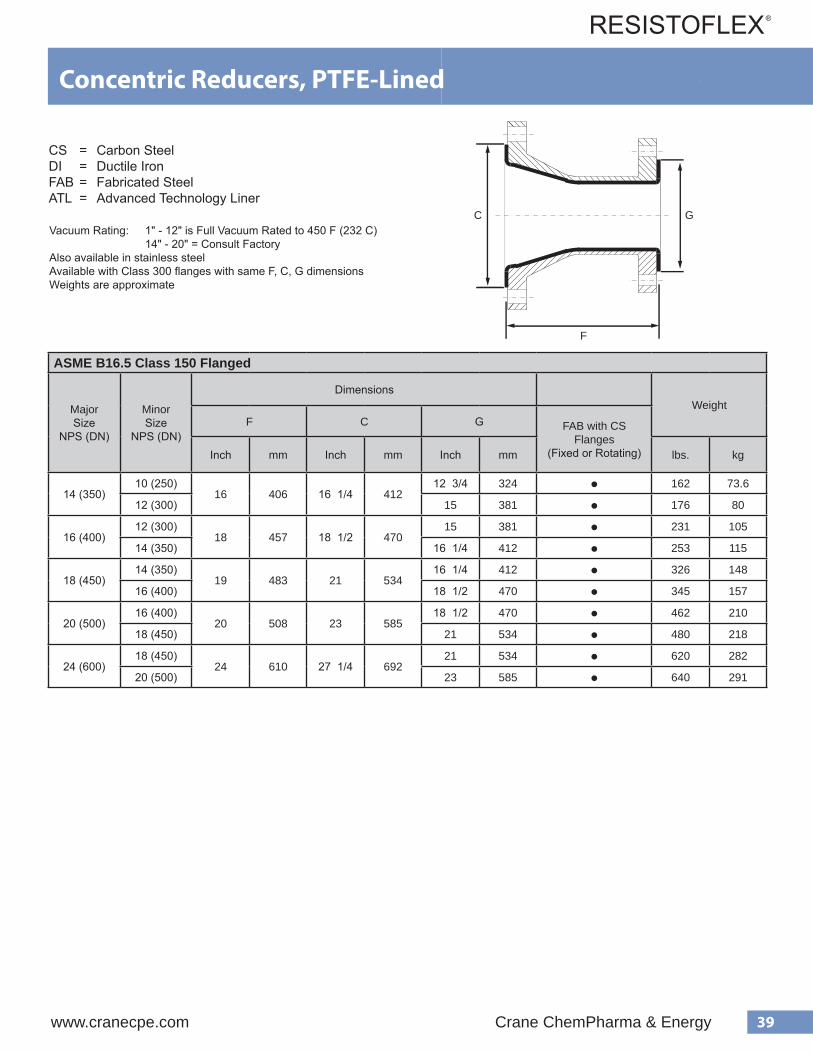
39www.cranecpe.com Crane ChemPharma & Energy
ASME B16.5 Class 150 Flanged
Major Size
NPS (DN)
Minor Size
NPS (DN)
DimensionsWeight
F C G FAB with CS Flanges
(Fixed or Rotating)Inch mm Inch mm Inch mm lbs. kg
14 (350)10 (250)
16 406 16 1/4 41212 3/4 324 ● 162 73.6
12 (300) 15 381 ● 176 80
16 (400)12 (300)
18 457 18 1/2 47015 381 ● 231 105
14 (350) 16 1/4 412 ● 253 115
18 (450)14 (350)
19 483 21 53416 1/4 412 ● 326 148
16 (400) 18 1/2 470 ● 345 157
20 (500)16 (400)
20 508 23 58518 1/2 470 ● 462 210
18 (450) 21 534 ● 480 218
24 (600)18 (450)
24 610 27 1/4 69221 534 ● 620 282
20 (500) 23 585 ● 640 291
CS = Carbon SteelDI = Ductile IronFAB = Fabricated SteelATL = Advanced Technology Liner C G
F
Concentric Reducers, PTFE-Lined
Vacuum Rating: 1" - 12" is Full Vacuum Rated to 450 F (232 C)14" - 20" = Consult Factory
Also available in stainless steelAvailable with Class 300 flanges with same F, C, G dimensions Weights are approximate

40 Crane ChemPharma & Energy www.cranecpe.com
ASME B16.5 Class 150 Flanged
Major Size
NPS (DN)
Minor Size
NPS (DN)
Dimensions Available ConstructionWeight
F C GFAB with CS
Fixed FlangesCast SteelA216 WCB
CastDI
A395ATL
Inch mm Inch mm Inch mm lbs. kg
1 (25)1/2 (15)
4 1/2 114 2 511 3/4 35 ● ● 6.5 3
3/4 (20) 1 11/16 43 ● ● 6.8 3.1
1 1/2 (40) 1 (25) 4 1/2 114 2 7/8 73 2 51 ● ● ● 8.3 3.8
2 (50)1 (25)
5 127 3 5/8 922 51 ● ● ● 9 4.1
1 1/2 (40) 2 7/8 73 ● ● ● 11 5
3 (80)1 1/2 (40)
6 152 5 1272 7/8 73 ● ● ● ● 15 6.8
2 (50) 3 5/8 92 ● ● ● ● 17 7.7
4 (100)
1 1/2 (40)
7 178 6 3/16 157
2 7/8 73 ● ● ● 22.3 10.1
2 (50) 3 5/8 92 ● ● ● ● 24.6 11.2
3 (80) 5 127 ● ● ● ● 29 13.2
6 (150)3 (80)
9 229 8 1/2 2165 127 ● ● ● ● 44.5 20.2
4 (100) 6 3/16 157 ● ● ● ● 51.5 23.4
8 (200)4 (100)
11 279 10 5/8 2706 3/16 157 ● ● ● ● 75.4 34.3
6 (150) 8 1/2 216 ● ● ● ● 84 38.2
10 (250)6 (150)
12 305 12 3/4 3248 1/2 216 ● 116 52.7
8 (200) 10 5/8 270 ● 132 60
12 (300)
6 (150)
14 356 15 381
8 1/2 216 ● 144 65.5
8 (200) 10 5/8 270 ● 170 77.3
10 (250) 12 3/4 324 ● 190 86.4
CS = Carbon SteelDI = Ductile IronFAB = Fabricated SteelATL = Advanced Technology Liner
Eccentric Reducers, PTFE-Lined
Vacuum Rating: 1" - 8 is Full Vacuum Rated to 450 F (232 C) 10" - 20" = Consult FactoryAlso available in stainless steelAvailable with Class 300 flanges with same F, C, D dimensions Weights are approximate
C
F
G
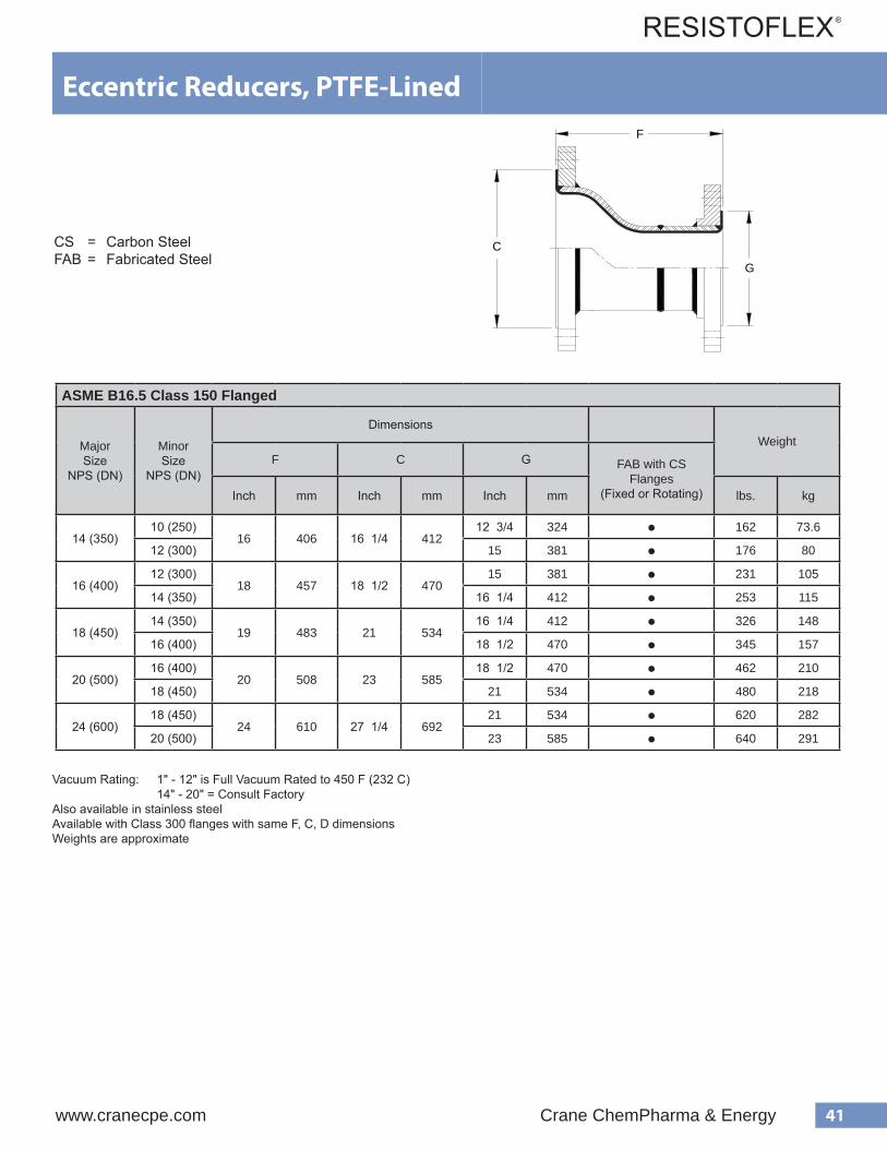
41www.cranecpe.com Crane ChemPharma & Energy
ASME B16.5 Class 150 Flanged
Major Size
NPS (DN)
Minor Size
NPS (DN)
DimensionsWeight
F C G FAB with CS Flanges
(Fixed or Rotating)Inch mm Inch mm Inch mm lbs. kg
14 (350)10 (250)
16 406 16 1/4 41212 3/4 324 ● 162 73.6
12 (300) 15 381 ● 176 80
16 (400)12 (300)
18 457 18 1/2 47015 381 ● 231 105
14 (350) 16 1/4 412 ● 253 115
18 (450)14 (350)
19 483 21 53416 1/4 412 ● 326 148
16 (400) 18 1/2 470 ● 345 157
20 (500)16 (400)
20 508 23 58518 1/2 470 ● 462 210
18 (450) 21 534 ● 480 218
24 (600)18 (450)
24 610 27 1/4 69221 534 ● 620 282
20 (500) 23 585 ● 640 291
CS = Carbon SteelFAB = Fabricated Steel
Vacuum Rating: 1" - 12" is Full Vacuum Rated to 450 F (232 C)14" - 20" = Consult Factory
Also available in stainless steelAvailable with Class 300 flanges with same F, C, D dimensions Weights are approximate
Eccentric Reducers, PTFE-Lined
C
F
G

42 Crane ChemPharma & Energy www.cranecpe.com
ASME B16.5 Class 150 Flanged
Major Size
NPS (DN)
Minor Size
NPS (DN)
Thickness,B
inch (mm)
H - Bolt Holes E - Bolt HolesBoltHole
RotationNo. Size
BoltCircle Dia.
Ginch (mm)
No. Size
BoltCircle Dia.
Dinch (mm)
DepthF
inch (mm)
1 (25)1/2 (15)
1 5/8 (41) 4 5/8 3 1/8 (79) 4 1/2-132 3/8 (67)
7/8 (22) 45o
3/4 (20) 2 3/4 (70)
1 1/2 (40) 1 (25) 1 9/16 (40) 4 5/8 3 7/8 (98) 4 1/2-13 3 1/8 (79) 7/8 (22) 45o
2 (50)1 (25)
1 9/16 (40) 4 3/4 4 3/4 (121) 4 1/2-133 1/8 (79)
7/8 (22) 45o
1 1/2 (40) 3 7/8 (98)
2 1/2 (65) 2 (50) 1 9/16 (40) 4 3/4 5 1/2 (140) 4 5/8-11 4 3/4 (121) 7/8 (22) 45o
3 (80)
1 (25)1 5/8 (41)
4 3/4 6 (152) 4
1/2-133 1/8 (79) 3/4 (19)
45o1 1/2 (40) 3 7/8 (98)
7/8 (22)2 (50) 1 3/4 (44)5/8-11
4 3/4 (121)
2 1/2 (65) 1 5/8 (41) 5 1/2 (140)
4 (100)
1 (25) 1 7/8 (48)
8 3/4 7 1/2 (191) 4
1/2-133 1/8 (79) 11/16 (17)
0o1 1/2 (40) 1 5/8 (41) 3 7/8 (98)
7/8 (22)2 (50) 2 (51)5/8-11
4 3/4 (121)
3 (80) 1 3/4 (44) 6 (152)
5 (125) 4 (100) 1 5/8 (41) 8 7/8 8 1/2 (216) 8 5/8-11 7 1/2 (191) 1 (25) 22.5o
6 (150)
1 1/2 (40)1 7/8 (48)
8 7/8 9 1/2 (241)
4
1/2-13 3 7/8 (98) 11/16 (17)
0o2 (50)
5/8-11
4 3/4 (121) 3/4 (19)
3 (80) 1 3/4 (44) 6 (152) 1 (25)
4 (100) 2 1/8 (54)8
7 1/2 (191) 7/8 (22)22.5o
5 (125) 11 3/4 (44) 3/4-10 8 1/2 (216) 1 (25)
8 (200)4 (100)
2 (51) 8 7/8 11 3/4 (298) 85/8-11 7 1/2 (191) 7/8 (22) 22.5o
6 (150) 3/4-10 9 1/2 (241) 1 1/8 (29) 0o
10 (250)
4 (100)
2 7/16 (62) 12 1 14 1/4 (362) 8
5/8-11 7 1/2 (191) 7/8 (22)
0o6 (150)3/4-10
9 1/2 (241)1 (25)
8 (200) 11 3/4 (298)
Ductile Iron Reducing Filler Flanges, PTFE-Lined
All sizes available lined with ATL All sizes rated for Full Vacuum to 450 F (232 C)Consult factory for weightsDimension "A" = ASME Class 150 Flange OD
35

43www.cranecpe.com Crane ChemPharma & Energy
ASME B16.5 Class 150 Flanged
Major Size
NPS (DN)
Minor Size
NPS (DN)
Thickness,B
inch (mm)
H - Bolt Holes* E - Bolt HolesBoltHole
RotationNo. Size
BoltCircle Dia.
Ginch (mm)
No. Size
BoltCircle Dia.
Dinch (mm)
DepthF
inch (mm)
1 (25)1/2 (15)
1 1/2 (38) 4 1/2-13 3 1/8 (79) 4 1/2-132 3/8 (67)
11/16 (17) 45o
3/4 (20) 2 3/4 (70)
1 1/2 (40) 1 (25) 1 1/2 (38) 4 1/2-13 3 7/8 (98) 4 1/2-13 3 1/8 (79) 9/16 (14) 45o
2 (50)1 (25)
1 1/2 (38) 4 5/8-11 4 3/4 (121) 4 1/2-133 1/8 (79) 9/16 (14) 0o
1 1/2 (40) 3 7/8 (98) 5/8 (16) 45o
3 (80)
1 (25)
1 1/2 (38) 4 5/8-11 6 (152) 41/2-13
3 1/8 (79) 9/16 (14)0o
1 1/2 (40) 3 7/8 (98) 5/8 (16)
2 (50) 5/8-11 4 3/4 (121) 3/4 (19) 45o
4 (100)
1 (25)2 (51)
83/4
7 1/2 (191) 4
1/2-133 1/8 (79) 9/16 (14)
0o1 1/2 (40) 3 7/8 (98) 5/8 (16)
2 (50)1 1/2 (38) 5/8-11
4 3/4 (121)3/4 (19)
3 (80) 5/8-11 6 (152)
6 (150)
1 1/2 (40)
2 (51)8
7/8
9 1/2 (241)4
1/2-13 3 7/8 (98) 9/16 (14)
0o2 (50)
3/4-10 5/8-11
4 3/4 (121) 5/8 (16)
3 (80) 6 (152)3/4 (19)
4 (100) 1 1/2 (38) 8 7 1/2 (191)
8 (200)
3 (802
87/8
11 3/4 (298)
45/8-11
6 (152)3/4 (19)
0o4 (100)8
7 1/2 (191)
6 (150) 1 1/2 (38) 3/4-10 3/4-10 9 1/2 (241) 13/16 (21)
10 (250)
3 (80)
2 (51) 121
14 1/4 (362)
45/8-11
6 (152) 5/8 (16)
0o4 (100)
8
7 1/2 (191) 3/4 (19)
6 (150)3/4-10
9 1/2 (241)13/16 (21)
8 (200) 7/8-9 11 3/4 (298)
12 (300)
6 (150)
2 (51)8 3/4-10
17 (432)8 3/4-10
9 1/2 (241) 13/16 (21)
0o8 (200) 11 3/4 (298)1 1/4 (32)
10 (250 12 7/8-9 12 7/8-9 14 1/4 (362)
All sizes available lined with ATL 1" - 8" rated for Full Vacuum to 450 F (232 C)10" - 12" are not vacuum ratedConsult factory for weightsDimension "A" = ASME Class 150 Flange ODAlso available in stainless steel
Carbon Steel Reducing Filler Flanges, PTFE-Lined
* Most "H" bolt holes are threaded. Example: In above table, 5/8-11 is threaded. 7/8 is not threaded.
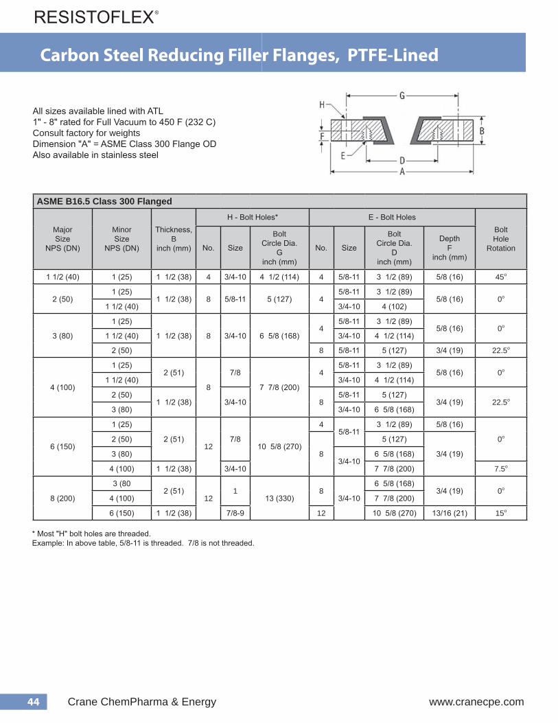
44 Crane ChemPharma & Energy www.cranecpe.com
ASME B16.5 Class 300 Flanged
Major Size
NPS (DN)
Minor Size
NPS (DN)
Thickness,B
inch (mm)
H - Bolt Holes* E - Bolt HolesBoltHole
RotationNo. Size
BoltCircle Dia.
Ginch (mm)
No. Size
BoltCircle Dia.
Dinch (mm)
DepthF
inch (mm)
1 1/2 (40) 1 (25) 1 1/2 (38) 4 3/4-10 4 1/2 (114) 4 5/8-11 3 1/2 (89) 5/8 (16) 45o
2 (50)1 (25)
1 1/2 (38) 8 5/8-11 5 (127) 45/8-11 3 1/2 (89)
5/8 (16) 0o
1 1/2 (40) 3/4-10 4 (102)
3 (80)
1 (25)
1 1/2 (38) 8 3/4-10 6 5/8 (168)4
5/8-11 3 1/2 (89)5/8 (16) 0o
1 1/2 (40) 3/4-10 4 1/2 (114)
2 (50) 8 5/8-11 5 (127) 3/4 (19) 22.5o
4 (100)
1 (25)2 (51)
8
7/8
7 7/8 (200)
45/8-11 3 1/2 (89)
5/8 (16) 0o
1 1/2 (40) 3/4-10 4 1/2 (114)
2 (50)1 1/2 (38) 3/4-10 8
5/8-11 5 (127)3/4 (19) 22.5o
3 (80) 3/4-10 6 5/8 (168)
6 (150)
1 (25)
2 (51)12
7/810 5/8 (270)
45/8-11
3 1/2 (89) 5/8 (16)
0o2 (50)
8
5 (127)
3/4 (19)3 (80)3/4-10
6 5/8 (168)
4 (100) 1 1/2 (38) 3/4-10 7 7/8 (200) 7.5o
8 (200)
3 (802 (51)
121
13 (330)8
3/4-10
6 5/8 (168)3/4 (19) 0o
4 (100) 7 7/8 (200)
6 (150) 1 1/2 (38) 7/8-9 12 10 5/8 (270) 13/16 (21) 15o
All sizes available lined with ATL 1" - 8" rated for Full Vacuum to 450 F (232 C)Consult factory for weightsDimension "A" = ASME Class 300 Flange ODAlso available in stainless steel
Carbon Steel Reducing Filler Flanges, PTFE-Lined
* Most "H" bolt holes are threaded. Example: In above table, 5/8-11 is threaded. 7/8 is not threaded.

45www.cranecpe.com Crane ChemPharma & Energy
ASME B16.5 Class 150 Flanged
Major Size
NPS (DN)
Minor Size
NPS (DN)
Thickness,B
inch (mm)
H - Bolt Holes* E - Bolt HolesBoltHole
RotationNo. Size
BoltCircle Dia.
Ginch (mm)
No. Size
BoltCircle Dia.
Dinch (mm)
DepthF
inch (mm)
1 1/2 (40)
1/2 (15)
PFA 13/16 (21) 4 1/2-13 3 7/8 (98) 4 1/2-13
2 3/8 (67) 7/16 (11)
45o3/4 (20) 2 3/4 (70)1/2 (13)
1 1/4 (32) 3 1/2 (89)
2 (50)
1/2 (15)
PFA 7/8 (22) 4 5/8-11 4 3/4 (121) 4 1/2-13
2 3/8 (67)
1/2 (13) 45o3/4 (20) 2 3/4 (70)
1 1/4 (32) 3 1/2 (89)
2 1/2 (65)
1 (25)PFA
1 (25) 4
3/4
5 1/2 (140) 41/2-13
3 1/8 (79)5/8 (16)
0o
1 1/2 (40)5/8-11
3 7/8 (98)45o
2 (50) PTFE 5/8-11 4 3/4 (121) 9/16 (14)
3 (80)1 1/4 (32) PFA
1 3/16 (30) 4 5/8-11 6 (152) 41/2-13 3 1/2 (89) 1/2 (13)
45o
2 1/2 (65) PTFE 5/8-11 5 1/2 (140) 9/16 (14)
4 (100) 2 1/2 (65) PTFE 1 3/16 (30) 8 5/8-11 7 1/2 (191) 4 5/8-11 5 1/2 (140) 11/16 (17) 0o
5 (125)2 (50)
PTFE 1 3/16 (30) 87/8
8 1/2 (216) 4 5/8-114 3/4 (121)
11/16 (17) 0o
3 (80) 3/4-10 6 (152)
6 (150) 3/4 (20) PFA 1 1/4 (32) 8 7/8 9 1/2 (241) 4 1/2-13 2 3/4 (70) 11/16 (17) 0o
8 (200)
1 (25)PFA
1 3/8 (35) 8 7/8 11 3/4 (298) 4
1/2-133 1/8 (79) 11/16 (17)
0o1 1/2 (40) 3 7/8 (98) 5/8 (16)
2 (50) PTFE 5/8-11 4 3/4 (121) 11/16 (17)
10 (250)
1 (25)PFA
1 7/16 (37) 12 1 14 1/4 (362) 4
1/2-133 1/8 (79) 3/4 (19)
0o1 1/2 (40) 3 7/8 (98) 11/16 (17)
2 (50) PTFE 5/8-11 4 3/4 (121) 3/4 (19)
12 (300)
1 (25)PFA
1 1/2 (38) 12 1 17 (432)4
1/2-133 1/8 (79) 7/8 (22)
0o1 1/2 (40) 3 7/8 (98)
3/4 (19)2 (50)
PTFE 5/8-11
4 3/4 (121)
3 (80) 6 (152)
4 (100) 8 7 1/2 (191) 15o
Carbon Steel Reducing Filler Flanges, PFA/PTFE-LinedNon-Standard Sizes
Not vacuum ratedConsult factory for weightsDimension "A" = ASME Class 150 Flange ODAlso available in stainless steel
* Most "H" bolt holes are threaded. Example: In above table, 5/8-11 is threaded. 7/8 is not threaded.
* Most "H" bolt holes are threaded. Example: In above table, 5/8-11 is threaded. 7/8 is not threaded.

46 Crane ChemPharma & Energy www.cranecpe.com
ASME B16.5 Class 150 Flanged
Major Size
NPS (DN)
Minor Size
NPS (DN)
Thickness,B
inch (mm)
H - Bolt Holes E - Bolt HolesBoltHole
RotationNo. Size
BoltCircle Dia.
Ginch (mm)
No. Size
BoltCircle Dia.
Dinch (mm)
DepthF
inch (mm)
12 (300)
1 (25)
1 1/2 (38) 12 1 17 (432)4
1/2-133 1/8 (79) 7/8 (22)
0o
1 1/2 (40) 3 7/8 (98)
3/4 (19)2 (50)
5/8-11
4 3/4 (121)
3 (80) 6 (152)
4 (100) 8 7 1/2 (191)
14 (350)
2 (50)
1 5/8 (41) 121 1/8
18 3/4 (476)
45/8-11
4 3/4 (121)11/16 (17)
0o
3 (80) 6 (152)
4 (100)
8
7 1/2 (191) 3/4 (19)
6 (150)3/4-10
9 1/2 (241)1 (25)
8 (200) 11 3/4 (298)
10 (250)12 7/8-9
14 1/4 (362)7/8 (22)
12 (300) 1-8 17 (432) 15o
16 (400)
3 (80)
1 11/16 (43)16
1 1/821 1/4 (540)
45/8-11
6 (152) 3/4 (19)
0o
4 (100)
8
7 1/2 (191) 3/4 (19)
6 (150)3/4-10
9 1/2 (241) 1 (25)
8 (200) 11 3/4 (298) 1 (25)
10 (250)
127/8-9
14 1/4 (362) 7/8 (22)
12 (300) 17 (432) 7/8 (22)
14 (350) 1 15/16 (49) 1-8 1-8 18 3/4 (476) 1 1/16 (27)
Not vacuum ratedConsult factory for weightsDimension "A" = ASME Class 150 Flange ODAlso available in stainless steel
Carbon Steel Reducing Filler Flanges, PTFE-LinedNon-Standard Sizes

47www.cranecpe.com Crane ChemPharma & Energy
ASME B16.5 Class 150 Flanged
Major SizeNPS (DN)
Minor SizeNPS (DN)
Thickness,B
inch (mm)
H - Bolt Holes* E - Bolt HolesBoltHole
RotationNo. Size
BoltCircle Dia.
Ginch (mm)
No. Size
BoltCircle Dia.
Dinch (mm)
DepthF
inch (mm)
18
3
1 13/16 (46) 16 1 1/4 22 3/4 (578)
45/8-11
6 (152) 3/4 (19)
0o
4
8
7 1/2 (191) 3/4 (19)
63/4-10
9 1/2 (241) 1 (25)
8 11 3/4 (298) 1 (25)
1012 7/8-9
14 1/4 (362) 7/8 (22)
12 17 (432) 1 (25)
20
3
1 15/16 (49) 201 1/4
25 (635)
4 5/8 - 11 6 (152) 3/4 (19)
0o8 8 3/4 - 10 11 3/4 (298) 1 (25)
12 12 7/8 - 9 17 (432) 1 1/8 (29)
18 1 1/8 - 7 16 1 1/8 - 7 22 3/4 (578) 1 1/8 (29)
24
3
2 1/8 (54) 20 1 3/8 29 1/2 (749)
4 5/8 - 11 6 (152) 11/16 (17)
0o6 8 3/4 - 10 9 1/2 (241) 3/4 (19)
10 12 7/8 - 9 14 1/4 (362) 1 (25)
12 12 7/8 - 9 17 (432) 1 (25)
Not vacuum ratedConsult factory for weightsDimension "A" = ASME Class 150 Flange ODAlso available in stainless steel
Carbon Steel Reducing Filler Flanges, PTFE-LinedNon-Standard Sizes, Class 150 Flanged
* Some "H" bolt holes are threaded. Example: In above table, 1 1/8 - 7 is threaded. 1 3/8 is not threaded.For sizes not shown, consult factory.
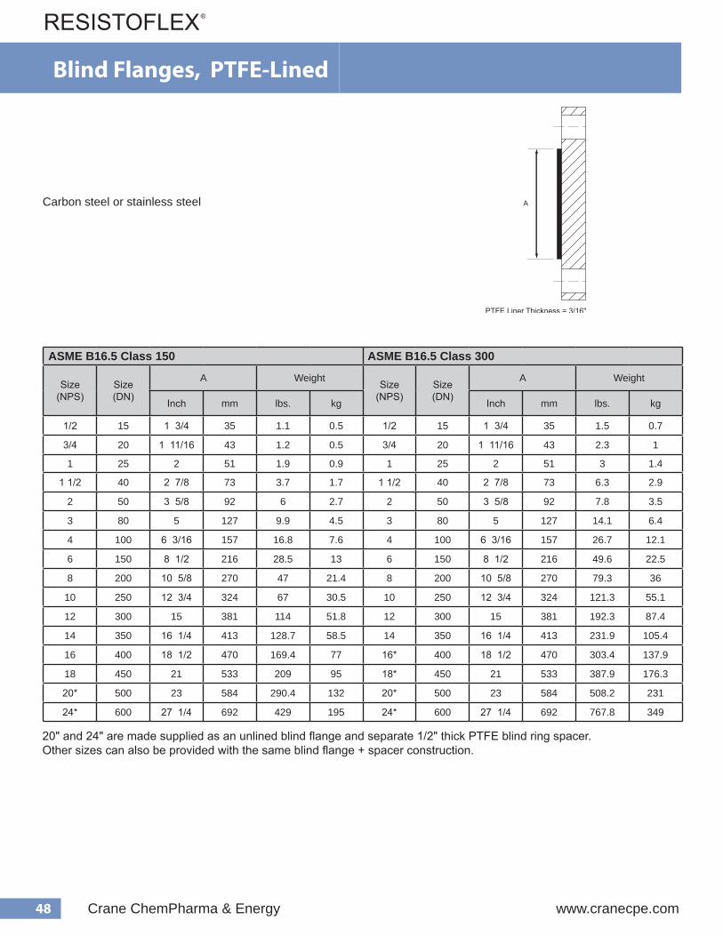
48 Crane ChemPharma & Energy www.cranecpe.com
Blind Flanges, PTFE-Lined
ASME B16.5 Class 150 ASME B16.5 Class 300
Size(NPS)
Size(DN)
A WeightSize
(NPS)Size(DN)
A Weight
Inch mm lbs. kg Inch mm lbs. kg
1/2 15 1 3/4 35 1.1 0.5 1/2 15 1 3/4 35 1.5 0.7
3/4 20 1 11/16 43 1.2 0.5 3/4 20 1 11/16 43 2.3 1
1 25 2 51 1.9 0.9 1 25 2 51 3 1.4
1 1/2 40 2 7/8 73 3.7 1.7 1 1/2 40 2 7/8 73 6.3 2.9
2 50 3 5/8 92 6 2.7 2 50 3 5/8 92 7.8 3.5
3 80 5 127 9.9 4.5 3 80 5 127 14.1 6.4
4 100 6 3/16 157 16.8 7.6 4 100 6 3/16 157 26.7 12.1
6 150 8 1/2 216 28.5 13 6 150 8 1/2 216 49.6 22.5
8 200 10 5/8 270 47 21.4 8 200 10 5/8 270 79.3 36
10 250 12 3/4 324 67 30.5 10 250 12 3/4 324 121.3 55.1
12 300 15 381 114 51.8 12 300 15 381 192.3 87.4
14 350 16 1/4 413 128.7 58.5 14 350 16 1/4 413 231.9 105.4
16 400 18 1/2 470 169.4 77 16* 400 18 1/2 470 303.4 137.9
18 450 21 533 209 95 18* 450 21 533 387.9 176.3
20* 500 23 584 290.4 132 20* 500 23 584 508.2 231
24* 600 27 1/4 692 429 195 24* 600 27 1/4 692 767.8 349
Carbon steel or stainless steel
20" and 24" are made supplied as an unlined blind flange and separate 1/2" thick PTFE blind ring spacer. Other sizes can also be provided with the same blind flange + spacer construction.

49www.cranecpe.com Crane ChemPharma & Energy
Spectacle Blind Flanges, PTFE-Lined
H
D
L
BA
ASME Class 150
Size DimensionsWeight
NPS DNA B D H L
Inch mm Inch mm Inch mm Inch mm Inch mm lb. kg
1/2 15 1 3/4 35 1 3/4 44 5/8 16 5/8 16 2 3/8 60 1.4 0.6
3/4 20 1 11/16 43 2 1/8 54 5/8 16 5/8 16 3 1/2 89 1.5 0.7
1 25 2 51 2 1/2 64 5/8 16 3/4 19 3 1/8 79 1.6 0.7
1 1/2 40 2 7/8 73 3 1/4 83 5/8 16 7/8 22 3 7/8 98 2.8 1.3
2 50 3 5/8 92 4 102 3/4 19 7/8 22 4 3/4 121 2.9 1.3
3 80 5 127 5 1/4 133 3/4 19 1 1/8 29 6 152 5.8 2.6
4 100 6 3/16 157 6 3/4 171 3/4 19 1 1/8 29 7 1/2 191 8 3.6
6 150 8 1/2 216 8 5/8 219 7/8 22 1 1/8 29 9 1/2 241 10.8 4.9
8 200 10 5/8 270 10 7/8 276 7/8 22 1 1/4 32 11 3/4 298 15.2 6.9
10 250 12 3/4 324 13 1/4 337 1 25 1 3/8 35 14 1/4 362 16 7.3
12 300 15 381 16 406 1 25 1 3/8 35 17 432 20 9.1
14 350 16 1/4 413 17 5/8 448 1 1/8 28.6 1 3/4 45 1 3/4 476.2 96.8 44
16 400 18 1/2 470 20 1/8 511 1 1/8 28.6 1 15/16 50 1 15/16 539.7 143 65
18 450 21 533 21 1/2 546 1 1/4 31.8 2 1/16 52 2 1/16 577.8 169.4 77
20 500 23 584 23 3/4 603 1 1/4 31.8 2 3/16 56 2 3/16 635 224.4 102
24 600 27 1/4 692 28 1/8 714 1 3/8 35.1 2 1/4 57 2 1/4 749.3 343.2 156
Not vacuum ratedConsult factory for weightsAlso available in stainless steelDimensions are not per ASME B16.48
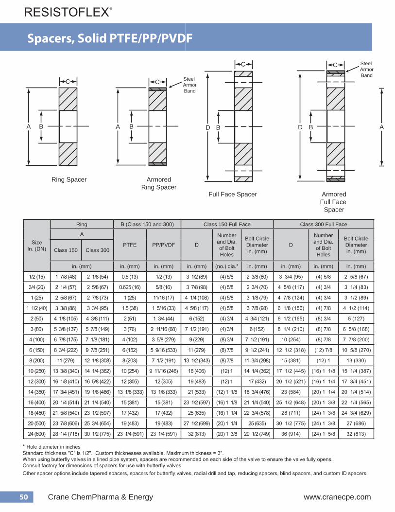
50 Crane ChemPharma & Energy www.cranecpe.com
SizeIn. (DN)
Ring B (Class 150 and 300) Class 150 Full Face Class 300 Full Face
A
PTFE PP/PVDF D
Number and Dia. of Bolt Holes
Bolt Circle Diameterin. (mm)
D
Number and Dia. of Bolt Holes
Bolt Circle Diameterin. (mm)Class 150 Class 300
in. (mm) in. (mm) in. (mm) in. (mm) (no.) dia.* in. (mm) in. (mm) in. (mm) in. (mm)
1/2 (15) 1 7/8 (48) 2 1/8 (54) 0.5 (13) 1/2 (13) 3 1/2 (89) (4) 5/8 2 3/8 (60) 3 3/4 (95) (4) 5/8 2 5/8 (67)
3/4 (20) 2 1/4 (57) 2 5/8 (67) 0.625 (16) 5/8 (16) 3 7/8 (98) (4) 5/8 2 3/4 (70) 4 5/8 (117) (4) 3/4 3 1/4 (83)
1 (25) 2 5/8 (67) 2 7/8 (73) 1 (25) 11/16 (17) 4 1/4 (108) (4) 5/8 3 1/8 (79) 4 7/8 (124) (4) 3/4 3 1/2 (89)
1 1/2 (40) 3 3/8 (86) 3 3/4 (95) 1.5 (38) 1 5/16 (33) 4 5/8 (117) (4) 5/8 3 7/8 (98) 6 1/8 (156) (4) 7/8 4 1/2 (114)
2 (50) 4 1/8 (105) 4 3/8 (111) 2 (51) 1 3/4 (44) 6 (152) (4) 3/4 4 3/4 (121) 6 1/2 (165) (8) 3/4 5 (127)
3 (80) 5 3/8 (137) 5 7/8 (149) 3 (76) 2 11/16 (68) 7 1/2 (191) (4) 3/4 6 (152) 8 1/4 (210) (8) 7/8 6 5/8 (168)
4 (100) 6 7/8 (175) 7 1/8 (181) 4 (102) 3 5/8 (279) 9 (229) (8) 3/4 7 1/2 (191) 10 (254) (8) 7/8 7 7/8 (200)
6 (150) 8 3/4 (222) 9 7/8 (251) 6 (152) 5 9/16 (533) 11 (279) (8) 7/8 9 1/2 (241) 12 1/2 (318) (12) 7/8 10 5/8 (270)
8 (200) 11 (279) 12 1/8 (308) 8 (203) 7 1/2 (191) 13 1/2 (343) (8) 7/8 11 3/4 (298) 15 (381) (12) 1 13 (330)
10 (250) 13 3/8 (340) 14 1/4 (362) 10 (254) 9 11/16 (246) 16 (406) (12) 1 14 1/4 (362) 17 1/2 (445) (16) 1 1/8 15 1/4 (387)
12 (300) 16 1/8 (410) 16 5/8 (422) 12 (305) 12 (305) 19 (483) (12) 1 17 (432) 20 1/2 (521) (16) 1 1/4 17 3/4 (451)
14 (350) 17 3/4 (451) 19 1/8 (486) 13 1/8 (333) 13 1/8 (333) 21 (533) (12) 1 1/8 18 3/4 (476) 23 (584) (20) 1 1/4 20 1/4 (514)
16 (400) 20 1/4 (514) 21 1/4 (540) 15 (381) 15 (381) 23 1/2 (597) (16) 1 1/8 21 1/4 (540) 25 1/2 (648) (20) 1 3/8 22 1/4 (565)
18 (450) 21 5/8 (549) 23 1/2 (597) 17 (432) 17 (432) 25 (635) (16) 1 1/4 22 3/4 (578) 28 (711) (24) 1 3/8 24 3/4 (629)
20 (500) 23 7/8 (606) 25 3/4 (654) 19 (483) 19 (483) 27 1/2 (699) (20) 1 1/4 25 (635) 30 1/2 (775) (24) 1 3/8 27 (686)
24 (600) 28 1/4 (718) 30 1/2 (775) 23 1/4 (591) 23 1/4 (591) 32 (813) (20) 1 3/8 29 1/2 (749) 36 (914) (24) 1 5/8 32 (813)
* Hole diameter in inchesStandard thickness "C" is 1/2". Custom thicknesses available. Maximum thickness = 3".When using butterfly valves in a lined pipe system, spacers are recommended on each side of the valve to ensure the valve fully opens.Consult factory for dimensions of spacers for use with butterfly valves.Other spacer options include tapered spacers, spacers for butterfly valves, radial drill and tap, reducing spacers, blind spacers, and custom ID spacers.
Full Face Spacer
Armored Ring Spacer
Ring Spacer
A
C
Armored Full Face
Spacer
D
C
A B B
C
D
C
B B
Steel ArmorBand
Steel ArmorBand
Full Face Spacer
Armored Ring Spacer
Ring Spacer
A
C
Armored Full Face
Spacer
D
C
A B B
C
D
C
B B
Steel ArmorBand
Steel ArmorBand
Spacers, Solid PTFE/PP/PVDF

51www.cranecpe.com Crane ChemPharma & Energy
Spectacle Blind Flanges PTFE-Lined
PTFE-Lined Ring Spacers
Available in 1/16" increments between minimum length and 3.00".
d e g n a l F . b l 0 5 1
e z i S ) S P N (
) . n i ( s n o i s n e m i D
A B D h t g n e L . n i M
1 8 / 5 2 4 / 3 2
2 / 1
5 . 1 8 / 3 3 8 / 3 1 8 / 7 2
2 8 / 1 4 4 / 3 1 8 / 5 3
3 8 / 3 5 4 / 3 2 5
4 8 / 7 6 4 / 3 3 6 1 / 3 6
6 4 / 3 8 2 3 / 3 2 5 2 / 1 8
8 1 1 6 1 / 1 1 7 8 / 5 0 1
1 0 1 8 / 3 3 1 6 1 / 1 1 9 4 / 3 2 1
2 1 8 / 1 6 1 2 3 / 1 2 1 1 5 1
Ring Style
Full Face Style
D
A
Ring Spacers, PTFE-Lined
ASME Class 150
Size Dimensions
NPS DNA D Minimum Length Maximum Length
Inch mm Inch mm Inch mm Inch mm
1/2 15 1 3/4 44 1 3/8 35
1/2 13
3 76
3/4 20 2 1/16 53 1 11/16 43
1 25 2 5/8 67 2 51
1 1/2 40 3 3/8 86 2 7/8 73
2 50 4 1/8 105 3 5/8 92
3 80 5 3/8 137 5 127
4 100 6 7/8 175 6 3/16 157
6 150 8 3/4 222 8 1/2 216 3/4 19
8 200 11 279 10 5/8 270
1 2510 250 13 3/8 340 12 3/4 324
12 300 16 1/8 410 15 381
14 350 17 5/8 447 16 1/4 412 1 9/16 40 12 1/2 318
16 400 20 1/16 510 18 1/2 470 1 9/16 40 18 3/4 476
18 450 21 1/2 545 21 534 1 9/16 40 13 3/8 340
20 500 23 3/4 602 23 585 2 3/8 60 14 3/8 365
24 600 28 1/8 714 27 1/4 692 2 3/8 60 14 3/4 375
Not vacuum ratedConsult factory for weightsAlso available in stainless steel
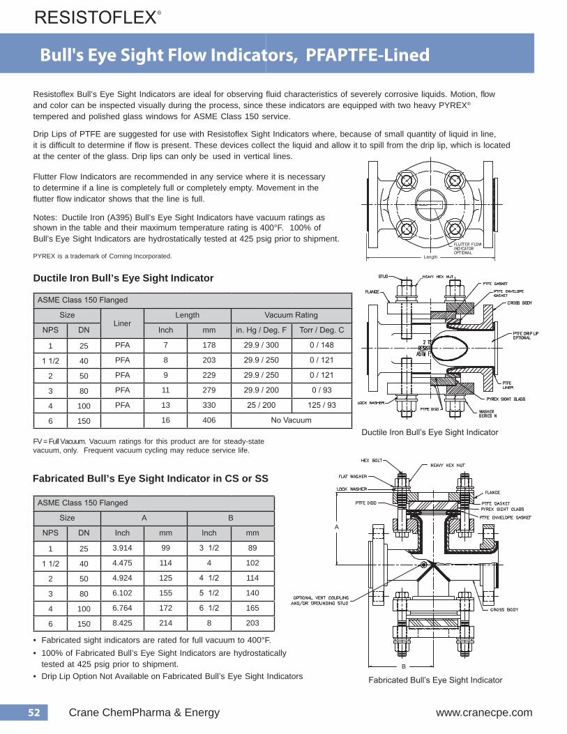
52 Crane ChemPharma & Energy www.cranecpe.com
Bull's Eye Sight Flow Indicators, PFAPTFE-Lined
Resistoflex Bull’s Eye Sight Indicators are ideal for observing fluid characteristics of severely corrosive liquids. Motion, flowand color can be inspected visually during the process, since these indicators are equipped with two heavy PYREX® tempered and polished glass windows for ASME Class 150 service.
Drip Lips of PTFE are suggested for use with Resistoflex Sight Indicators where, because of small quantity of liquid in line,it is difficult to determine if flow is present. These devices collect the liquid and allow it to spill from the drip lip, which is locatedat the center of the glass. Drip lips can only be used in vertical lines.
Flutter Flow Indicators are recommended in any service where it is necessary to determine if a line is completely full or completely empty. Movement in the flutter flow indicator shows that the line is full.
Notes: Ductile Iron (A395) Bull’s Eye Sight Indicators have vacuum ratings as shown in the table and their maximum temperature rating is 400°F. 100% of Bull’s Eye Sight Indicators are hydrostatically tested at 425 psig prior to shipment.
PYREX is a trademark of Corning Incorporated.
Ductile Iron Bull’s Eye Sight Indicator
Fabricated Bull’s Eye Sight Indicator in CS or SS
• Fabricated sight indicators are rated for full vacuum to 400°F.• 100% of Fabricated Bull’s Eye Sight Indicators are hydrostatically
• Drip Lip Option Not Available on Fabricated Bull’s Eye Sight Indicators tested at 425 psig prior to shipment.
FV = Full Vacuum. Vacuum ratings for this product are for steady-state vacuum, only. Frequent vacuum cycling may reduce service life.
ASME Class 150 Flanged
SizeLiner
Length Vacuum Rating
NPS DN Inch mm in. Hg / Deg. F Torr / Deg. C
1 25 PFA 7 178 29.9 / 300 0 / 148
1 1/2 40 PFA 8 203 29.9 / 250 0 / 121
2 50 PFA 9 229 29.9 / 250 0 / 121
3 80 PFA 11 279 29.9 / 200 0 / 93
4 100 PFA 13 330 25 / 200 125 / 93
6 150 16 406 No VacuumDuctile Iron Bull’s Eye Sight Indicator
Fabricated Bull’s Eye Sight Indicator
ASME Class 150 Flanged
Size A B
NPS DN Inch mm Inch mm
1 25 3.914 99 3 1/2 89
1 1/2 40 4.475 114 4 102
2 50 4.924 125 4 1/2 114
3 80 6.102 155 5 1/2 140
4 100 6.764 172 6 1/2 165
6 150 8.425 214 8 203
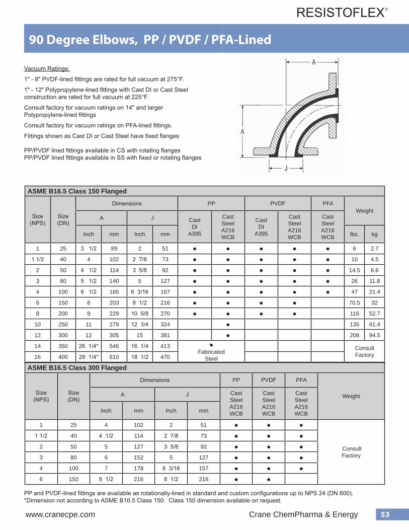
53www.cranecpe.com Crane ChemPharma & Energy
ASME B16.5 Class 150 Flanged
Size(NPS)
Size(DN)
Dimensions PP PVDF PFAWeight
A J CastDI
A395
CastSteelA216 WCB
CastDI
A395
CastSteelA216 WCB
CastSteelA216 WCBInch mm Inch mm lbs. kg
1 25 3 1/2 89 2 51 ● ● ● ● ● 6 2.7
1 1/2 40 4 102 2 7/8 73 ● ● ● ● ● 10 4.5
2 50 4 1/2 114 3 5/8 92 ● ● ● ● ● 14.5 6.6
3 80 5 1/2 140 5 127 ● ● ● ● ● 26 11.8
4 100 6 1/2 165 6 3/16 157 ● ● ● ● ● 47 21.4
6 150 8 203 8 1/2 216 ● ● ● ● 70.5 32
8 200 9 229 10 5/8 270 ● ● ● ● 116 52.7
10 250 11 279 12 3/4 324 ● 135 61.4
12 300 12 305 15 381 ● 208 94.5
14 350 26 1/4* 546 16 1/4 413 ●Fabricated
Steel
ConsultFactory16 400 29 1/4* 610 18 1/2 470
PP and PVDF-lined fittings are available as rotationally-lined in standard and custom configurations up to NPS 24 (DN 600).*Dimension not according to ASME B16.5 Class 150. Class 150 dimension available on request.
90 Degree Elbows, PP / PVDF / PFA-Lined
ASME B16.5 Class 300 Flanged
Size(NPS)
Size(DN)
Dimensions PP PVDF PFA
WeightA J CastSteelA216 WCB
CastSteelA216 WCB
CastSteelA216 WCBInch mm Inch mm
1 25 4 102 2 51 ● ● ●
ConsultFactory
1 1/2 40 4 1/2 114 2 7/8 73 ● ● ●2 50 5 127 3 5/8 92 ● ● ●3 80 6 152 5 127 ● ● ●4 100 7 178 6 3/16 157 ● ● ●6 150 8 1/2 216 8 1/2 216 ● ●
Vacuum Ratings:
1" - 8" PVDF-lined fittings are rated for full vacuum at 275°F.
1" - 12" Polypropylene-lined fittings with Cast DI or Cast Steel construction are rated for full vacuum at 225°F.
Consult factory for vacuum ratings on 14" and larger Polypropylene-lined fittings
Consult factory for vacuum ratings on PFA-lined fittings.
Fittings shown as Cast DI or Cast Steel have fixed flanges
PP/PVDF lined fittings available in CS with rotating flangesPP/PVDF lined fittings available in SS with fixed or rotating flanges
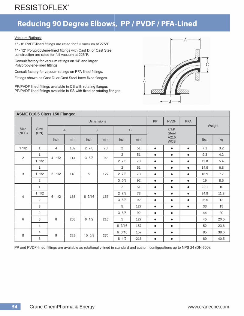
54 Crane ChemPharma & Energy www.cranecpe.com
ASME B16.5 Class 150 Flanged
Size(NPS)
Size(DN)
Dimensions PP PVDF PFAWeight
A J C CastSteelA216 WCBInch mm Inch mm Inch mm lbs. kg
1 1/2 1 4 102 2 7/8 73 2 51 ● ● ● 7.1 3.2
21
4 1/2 114 3 5/8 922 51 ● ● ● 9.3 4.2
1 1/2 2 7/8 73 ● ● ● 11.8 5.4
3
1
5 1/2 140 5 127
2 51 ● ● ● 14.9 6.8
1 1/2 2 7/8 73 ● ● ● 16.9 7.7
2 3 5/8 92 ● ● ● 19 8.6
4
1
6 1/2 165 6 3/16 157
2 51 ● ● ● 22.1 10
1 1/2 2 7/8 73 ● ● ● 24.8 11.3
2 3 5/8 92 ● ● ● 26.5 12
3 5 127 ● ● ● 33 15
6
2
8 203 8 1/2 216
3 5/8 92 ● ● 44 20
3 5 127 ● ● 45 20.5
4 6 3/16 157 ● ● 52 23.6
84
9 229 10 5/8 2706 3/16 157 ● ● 85 38.6
6 8 1/2 216 ● ● 89 40.5
Reducing 90 Degree Elbows, PP / PVDF / PFA-Lined
PP and PVDF-lined fittings are available as rotationally-lined in standard and custom configurations up to NPS 24 (DN 600).
Vacuum Ratings:
1" - 8" PVDF-lined fittings are rated for full vacuum at 275°F.
1" - 12" Polypropylene-lined fittings with Cast DI or Cast Steel construction are rated for full vacuum at 225°F.
Consult factory for vacuum ratings on 14" and larger Polypropylene-lined fittings
Consult factory for vacuum ratings on PFA-lined fittings.
Fittings shown as Cast DI or Cast Steel have fixed flanges
PP/PVDF lined fittings available in CS with rotating flangesPP/PVDF lined fittings available in SS with fixed or rotating flanges

55www.cranecpe.com Crane ChemPharma & Energy
45 Degree Elbows, PP / PVDF / PFA-Lined
ASME B16.5 Class 150 Flanged
Size(NPS)
Size(DN)
Dimensions PP PVDF PFAWeight
B J CastDI
A395
CastSteelA216 WCB
CastDI
A395
CastSteelA216 WCB
CastSteelA216 WCBInch mm Inch mm lbs. kg
1 25 1 3/4 45 2 51 ● ● ● ● ● 5.3 2.4
1 1/2 40 2 1/4 57 2 7/8 73 ● ● ● ● ● 8 3.6
2 50 2 1/2 64 3 5/8 92 ● ● ● ● ● 12.1 5.5
3 80 3 76 5 127 ● ● ● ● ● 21.5 9.8
4 100 4 102 6 3/16 157 ● ● ● ● ● 39.5 18
6 150 5 127 8 1/2 216 ● ● ● ● 57.5 26.1
8 200 5 1/2 140 10 5/8 270 ● ● ● ● 98.6 44.8
10 250 6 1/2 165 12 3/4 324 ● 100 45.5
12 300 7 1/2 190 15 381 ● 160 72.7
14 350 14* 190 16 1/4 413 ●Fabricated
Steel
ConsultFactory16 400 15 1/4* 203 18 1/2 470
ASME B16.5 Class 300 Flanged
Size(NPS)
Size(DN)
Dimensions PP PVDF PFA
WeightA J CastSteelA216 WCB
CastSteelA216 WCB
CastSteelA216 WCBInch mm Inch mm
1 25 2 1/4 57 2 51 ● ● ●
ConsultFactory
1 1/2 40 2 3/4 70 2 7/8 73 ● ● ●2 50 3 76 3 5/8 92 ● ● ●3 80 3 1/2 89 5 127 ● ● ●4 100 4 1/2 114 6 3/16 157 ● ● ●6 150 5 1/2 140 8 1/2 216 ● ●
PP and PVDF-lined fittings are available as rotationally-lined in standard and custom configurations up to NPS 24 (DN 600).*Dimension not according to ASME B16.5 Class 150. Class 150 dimension available on request.
Vacuum Ratings:
1" - 8" PVDF-lined fittings are rated for full vacuum at 275°F.
1" - 12" Polypropylene-lined fittings with Cast DI or Cast Steel construction are rated for full vacuum at 225°F.
Consult factory for vacuum ratings on 14" and larger Polypropylene-lined fittings
Consult factory for vacuum ratings on PFA-lined fittings.
Fittings shown as Cast DI or Cast Steel have fixed flanges
PP/PVDF lined fittings available in CS with rotating flangesPP/PVDF lined fittings available in SS with fixed or rotating flanges

56 Crane ChemPharma & Energy www.cranecpe.com
Equal Tees, PP / PVDF / PFA-Lined
ASME B16.5 Class 150 Flanged
Size(NPS)
Size(DN)
Dimensions PP PVDF PFAWeight
A J CastDI
A395
CastSteelA216 WCB
CastDI
A395
CastSteelA216 WCB
CastSteelA216 WCBInch mm Inch mm lbs. kg
1 25 3 1/2 89 2 51 ● ● ● ● ● 9.5 4.3
1 1/2 40 4 102 2 7/8 73 ● ● ● ● ● 14 6.4
2 50 4 1/2 114 3 5/8 92 ● ● ● ● ● 20.5 9.3
3 80 5 1/2 140 5 127 ● ● ● ● ● 40 18.2
4 100 6 1/2 165 6 3/16 157 ● ● ● ● ● 65 29.5
6 150 8 203 8 1/2 216 ● ● ● ● ● 100 45.5
8 200 9 229 10 5/8 270 ● ● ● ● 183 83.2
10 250 11 279 12 3/4 324 ● ● ● 257 116.8
12 300 12 305 15 381 ● ● ● 395 179.5
14 350 16 1/4* 413 16 1/4 413 ●Fabricated
Steel
ConsultFactory16 400 17 1/4* 438 18 1/2 470
ASME B16.5 Class 300 Flanged
Size(NPS)
Size(DN)
Dimensions PP PVDF PFA
WeightA J CastSteelA216 WCB
CastSteelA216 WCB
CastSteelA216 WCBInch mm Inch mm
1 25 4 102 2 51 ● ● ●
ConsultFactory
1 1/2 40 4 1/2 114 2 7/8 73 ● ● ●2 50 5 127 3 5/8 92 ● ● ●3 80 6 152 5 127 ● ● ●4 100 7 178 6 3/16 157 ● ● ●6 150 8 1/2 216 8 1/2 216 ● ●
PP and PVDF-lined fittings are available as rotationally-lined in standard and custom configurations up to NPS 24 (DN 600).*Dimension not according to ASME B16.5 Class 150. Class 150 dimension available on request.
Vacuum Ratings:
1" - 8" PVDF-lined fittings are rated for full vacuum at 275°F.
1" - 12" Polypropylene-lined fittings with Cast DI or Cast Steel construction are rated for full vacuum at 225°F.
Consult factory for vacuum ratings on 14" and larger Polypropylene-lined fittings
Consult factory for vacuum ratings on PFA-lined fittings.
Fittings shown as Cast DI or Cast Steel have fixed flanges
PP/PVDF lined fittings available in CS with rotating flangesPP/PVDF lined fittings available in SS with fixed or rotating flanges
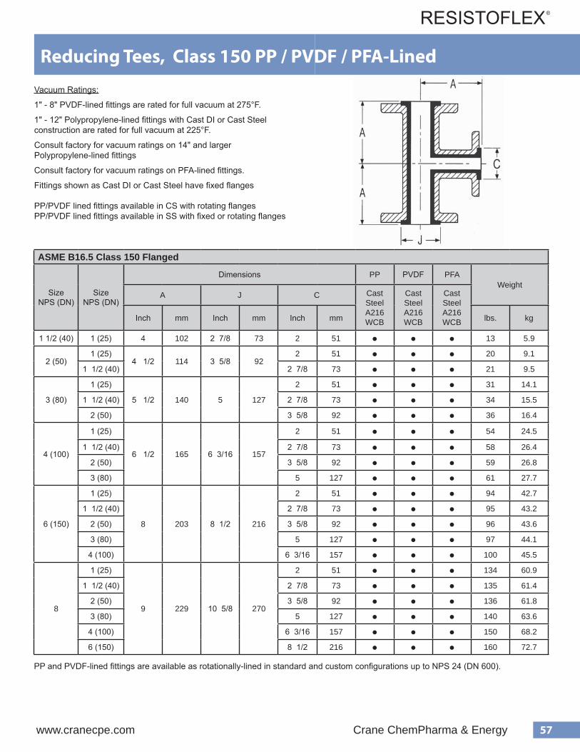
57www.cranecpe.com Crane ChemPharma & Energy
ASME B16.5 Class 150 Flanged
SizeNPS (DN)
SizeNPS (DN)
Dimensions PP PVDF PFAWeight
A J C CastSteelA216 WCB
CastSteelA216 WCB
CastSteelA216 WCBInch mm Inch mm Inch mm lbs. kg
1 1/2 (40) 1 (25) 4 102 2 7/8 73 2 51 ● ● ● 13 5.9
2 (50)1 (25)
4 1/2 114 3 5/8 922 51 ● ● ● 20 9.1
1 1/2 (40) 2 7/8 73 ● ● ● 21 9.5
3 (80)
1 (25)
5 1/2 140 5 127
2 51 ● ● ● 31 14.1
1 1/2 (40) 2 7/8 73 ● ● ● 34 15.5
2 (50) 3 5/8 92 ● ● ● 36 16.4
4 (100)
1 (25)
6 1/2 165 6 3/16 157
2 51 ● ● ● 54 24.5
1 1/2 (40) 2 7/8 73 ● ● ● 58 26.4
2 (50) 3 5/8 92 ● ● ● 59 26.8
3 (80) 5 127 ● ● ● 61 27.7
6 (150)
1 (25)
8 203 8 1/2 216
2 51 ● ● ● 94 42.7
1 1/2 (40) 2 7/8 73 ● ● ● 95 43.2
2 (50) 3 5/8 92 ● ● ● 96 43.6
3 (80) 5 127 ● ● ● 97 44.1
4 (100) 6 3/16 157 ● ● ● 100 45.5
8
1 (25)
9 229 10 5/8 270
2 51 ● ● ● 134 60.9
1 1/2 (40) 2 7/8 73 ● ● ● 135 61.4
2 (50) 3 5/8 92 ● ● ● 136 61.8
3 (80) 5 127 ● ● ● 140 63.6
4 (100) 6 3/16 157 ● ● ● 150 68.2
6 (150) 8 1/2 216 ● ● ● 160 72.7
Reducing Tees, Class 150 PP / PVDF / PFA-Lined
PP and PVDF-lined fittings are available as rotationally-lined in standard and custom configurations up to NPS 24 (DN 600).
Vacuum Ratings:
1" - 8" PVDF-lined fittings are rated for full vacuum at 275°F.
1" - 12" Polypropylene-lined fittings with Cast DI or Cast Steel construction are rated for full vacuum at 225°F.
Consult factory for vacuum ratings on 14" and larger Polypropylene-lined fittings
Consult factory for vacuum ratings on PFA-lined fittings.
Fittings shown as Cast DI or Cast Steel have fixed flanges
PP/PVDF lined fittings available in CS with rotating flangesPP/PVDF lined fittings available in SS with fixed or rotating flanges
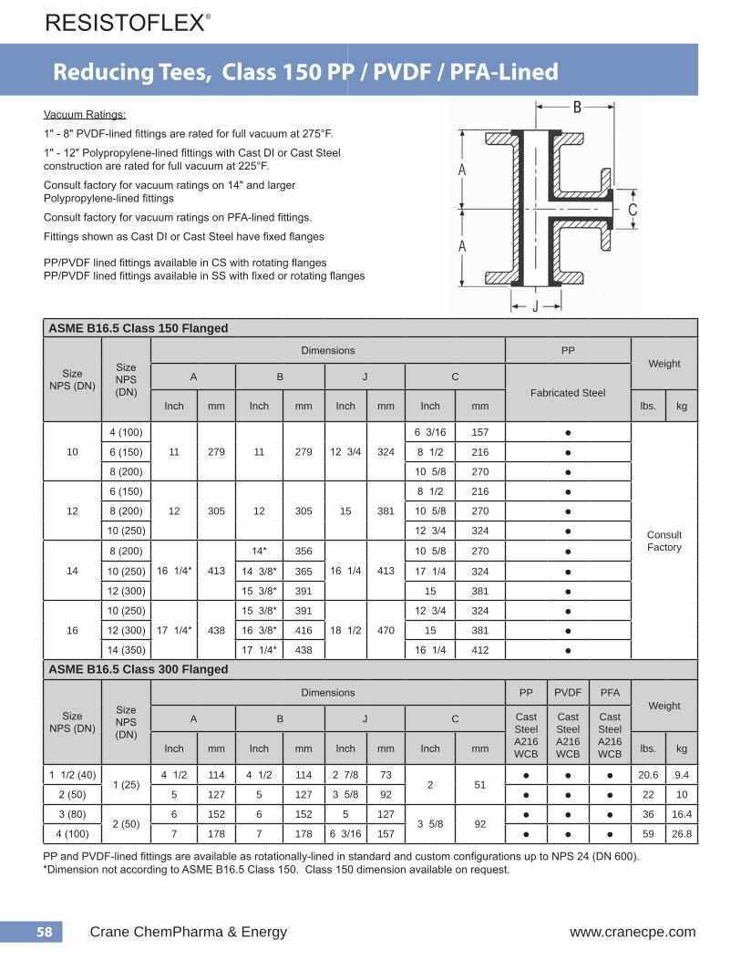
58 Crane ChemPharma & Energy www.cranecpe.com
ASME B16.5 Class 150 Flanged
SizeNPS (DN)
SizeNPS (DN)
Dimensions PPWeight
A B J CFabricated Steel
Inch mm Inch mm Inch mm Inch mm lbs. kg
10
4 (100)
11 279 11 279 12 3/4 324
6 3/16 157 ●
ConsultFactory
6 (150) 8 1/2 216 ●8 (200) 10 5/8 270 ●
12
6 (150)
12 305 12 305 15 381
8 1/2 216 ●8 (200) 10 5/8 270 ●
10 (250) 12 3/4 324 ●
14
8 (200)
16 1/4* 413
14* 356
16 1/4 413
10 5/8 270 ●10 (250) 14 3/8* 365 17 1/4 324 ●12 (300) 15 3/8* 391 15 381 ●
16
10 (250)
17 1/4* 438
15 3/8* 391
18 1/2 470
12 3/4 324 ●12 (300) 16 3/8* 416 15 381 ●14 (350) 17 1/4* 438 16 1/4 412 ●
ASME B16.5 Class 300 Flanged
SizeNPS (DN)
SizeNPS (DN)
Dimensions PP PVDF PFAWeight
A B J C CastSteelA216 WCB
CastSteelA216 WCB
CastSteelA216 WCBInch mm Inch mm Inch mm Inch mm lbs. kg
1 1/2 (40)1 (25)
4 1/2 114 4 1/2 114 2 7/8 732 51
● ● ● 20.6 9.4
2 (50) 5 127 5 127 3 5/8 92 ● ● ● 22 10
3 (80)2 (50)
6 152 6 152 5 1273 5/8 92
● ● ● 36 16.4
4 (100) 7 178 7 178 6 3/16 157 ● ● ● 59 26.8
Reducing Tees, Class 150 PP / PVDF / PFA-Lined
Vacuum Ratings:
1" - 8" PVDF-lined fittings are rated for full vacuum at 275°F.
1" - 12" Polypropylene-lined fittings with Cast DI or Cast Steel construction are rated for full vacuum at 225°F.
Consult factory for vacuum ratings on 14" and larger Polypropylene-lined fittings
Consult factory for vacuum ratings on PFA-lined fittings.
Fittings shown as Cast DI or Cast Steel have fixed flanges
PP/PVDF lined fittings available in CS with rotating flangesPP/PVDF lined fittings available in SS with fixed or rotating flanges
B
PP and PVDF-lined fittings are available as rotationally-lined in standard and custom configurations up to NPS 24 (DN 600).*Dimension not according to ASME B16.5 Class 150. Class 150 dimension available on request.

59www.cranecpe.com Crane ChemPharma & Energy
ASME B16.5 Class 150 Flanged
Size(NPS)
Size(DN)
Dimensions PP PVDF PFAWeight
P J T CastSteelA216 WCB
CastSteelA216 WCB
CastSteelA216 WCBInch mm Inch mm Inch mm lbs. kg
1 x 1 25 x 25 3 1/2 89 2 51 2 5/8 67 ● ● ● 5 2.3
1 1/2 x 1 40 x 25 4 102 2 7/8 73 3 3/8 86 ● ● ● 7 3.2
2 x 1 50 x 25 4 1/2 114 3 5/8 92 4 1/8 105 ● ● ● 9 4.1
3 x 1 80 x 25 5 1/2 140 5 127 5 3/8 137 ● ● ● 11 5
4 x 1 100 x 25 6 1/2 165 6 3/16 157 6 3/4 171 ● ● ● 17 7.7
6 x 1 150 x 25 8 203 8 1/2 216 8 3/4 222 ● ● ● 21 9.5
8 x 1 200 x 25 9 229 10 5/8 270 11 279 ● ● ● 29 13.2
10 x 1 250 x 25 11 279 12 3/4 324 13 3/8 340 ● ● 69 31.4
12 x 1 300 x 25 12 305 15 381 16 1/8 410 ● ● 77 35
14 x 1 350 x 25 15 3/8 390 18 1/2 470 19 7/8 505 ●Fabricated
Steel
ConsultFactory16 x 1 400 x 25 17 3/4 450 21 534 21 1/4 540
ASME B16.5 Class 300 Flanged
Size(NPS)
Size(DN)
Dimensions PP PVDF PFAWeight
P J T CastSteelA216 WCB
CastSteelA216 WCB
CastSteelA216 WCB
Inch mm Inch mm Inch mm lbs. kg
1 x 1 25 x 25 4 102 2 51 2 7/8 73 ● ● ● 6 2.7
1 1/2 x 1 40 x 25 4 1/2 114 2 7/8 73 3 3/4 95 ● ● ● 8 3.6
2 x 1 50 x 25 5 127 3 5/8 92 4 3/8 111 ● ● ● 11 5
3 x 1 80 x 25 6 152 5 127 5 7/8 149 ● ● ● 13 5.9
4 x 1 100 x 25 7 178 6 3/16 157 7 1/8 181 ● ● ● 19 8.6
6 x 1 150 x 25 8 1/2 216 8 1/2 216 9 7/8 251 ● ● ● 23 10.5
1" Branch Instrument Tees, PP / PVDF / PFA-Lined
T400M300ZR110
T400M300ZRB10
T400M300ZR210
T400M300ZR310
T400M300ZR410
2" (51 mm)
Vacuum Ratings:
1" - 8" PVDF-lined fittings are rated for full vacuum at 275°F.
1" - 12" Polypropylene-lined fittings with Cast DI or Cast Steel construction are rated for full vacuum at 225°F.
Consult factory for vacuum ratings on 14" and larger Polypropylene-lined fittings
Consult factory for vacuum ratings on PFA-lined fittings.
Note: Fittings shown as Cast DI or Cast Steel have fixed flanges
PP/PVDF-lined available in stainless steel
PP and PVDF-lined fittings are available as rotationally-lined in standard and custom configurations up to NPS 24 (DN 600).
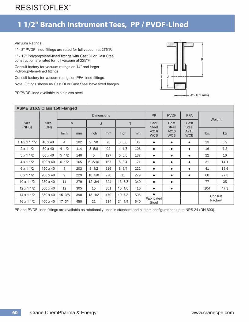
60 Crane ChemPharma & Energy www.cranecpe.com
ASME B16.5 Class 150 Flanged
Size(NPS)
Size(DN)
Dimensions PP PVDF PFAWeight
P J T CastSteelA216 WCB
CastSteelA216 WCB
CastSteelA216 WCBInch mm Inch mm Inch mm lbs. kg
1 1/2 x 1 1/2 40 x 40 4 102 2 7/8 73 3 3/8 86 ● ● ● 13 5.9
2 x 1 1/2 50 x 40 4 1/2 114 3 5/8 92 4 1/8 105 ● ● ● 16 7.3
3 x 1 1/2 80 x 40 5 1/2 140 5 127 5 3/8 137 ● ● ● 22 10
4 x 1 1/2 100 x 40 6 1/2 165 6 3/16 157 6 3/4 171 ● ● ● 31 14.1
6 x 1 1/2 150 x 40 8 203 8 1/2 216 8 3/4 222 ● ● ● 41 18.6
8 x 1 1/2 200 x 40 9 229 10 5/8 270 11 279 ● ● ● 60 27.3
10 x 1 1/2 250 x 40 11 279 12 3/4 324 13 3/8 340 ● ● 77 35
12 x 1 1/2 300 x 40 12 305 15 381 16 1/8 410 ● ● 104 47.3
14 x 1 1/2 350 x 40 15 3/8 390 18 1/2 470 19 7/8 505 ●Fabricated
Steel
ConsultFactory16 x 1 1/2 400 x 40 17 3/4 450 21 534 21 1/4 540
55
Instrument Tees with 1.5" Branch Polypropylene / PVDF / PFA-Lined Housing Materials CAST STEEL = ASTM A216
V acuum Ratings Polypropylene-lined fittings are rated for full vacuum at 225°F. PVDF-lined fittings are rated for full vacuum at 275°F. Consult factory for vacuum-ratings of PFA-lined fittings. Note: All PP / PVDF / PFA-lined fitting housings are castings, except for 6" and 8" size PFA. Flanged are fixed.
e z i S ) S P N (
g n i s u o H l a i r e t a M
l a i r e t a M r e n i L y b s r e b m u N t r a P ) . n i ( s n o i s n e m i D
e n e l y p o r p y l o P F D V P P T J S
5 . 1
T S A C L E E T S
0 B B N Z 0 0 2 P 0 0 4 T 0 B B N Z 0 0 2 K 0 0 4 T 4 8 / 3 3 6 1 / 1 1 2
2 0 B 2 N Z 0 0 2 P 0 0 4 T 0 B 2 N Z 0 0 2 K 0 0 4 T 2 / 1 4 8 / 1 4 6 1 / 7 3
3 0 B 3 N Z 0 0 2 P 0 0 4 T 0 B 3 N Z 0 0 2 K 0 0 4 T 2 / 1 5 8 / 3 5 8 / 5 4
4 0 B 4 N Z 0 0 2 P 0 0 4 T 0 B 4 N Z 0 0 2 K 0 0 4 T 2 / 1 6 4 / 3 6 6 1 / 5 1 5
6 0 B 6 N Z 0 0 2 P 0 0 4 T 0 B 6 N Z 0 0 2 K 0 0 4 T 8 4 / 3 8 8
8 0 B 8 N Z 0 0 2 P 0 0 4 T 0 B 8 N Z 0 0 2 K 0 0 4 T 9 1 1 6 1 / 1 0 1
0 1 0 B E N Z 0 0 2 P 0 0 4 T A / N
1 1 8 / 3 3 1 2 1
2 1 0 B F N Z 0 0 2 P 0 0 4 T 2 1 8 / 1 6 1 2 / 1 4 1
1 1 / 8
degnalF.bl051
4" (102 mm)
1 1/2" Branch Instrument Tees, PP / PVDF-Lined
Vacuum Ratings:
1" - 8" PVDF-lined fittings are rated for full vacuum at 275°F.
1" - 12" Polypropylene-lined fittings with Cast DI or Cast Steel construction are rated for full vacuum at 225°F.
Consult factory for vacuum ratings on 14" and larger Polypropylene-lined fittings
Consult factory for vacuum ratings on PFA-lined fittings.
Note: Fittings shown as Cast DI or Cast Steel have fixed flanges
PP/PVDF-lined available in stainless steel
PP and PVDF-lined fittings are available as rotationally-lined in standard and custom configurations up to NPS 24 (DN 600).
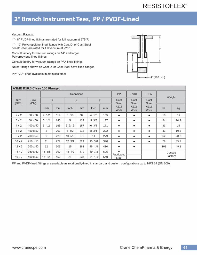
61www.cranecpe.com Crane ChemPharma & Energy
ASME B16.5 Class 150 Flanged
Size(NPS)
Size(DN)
Dimensions PP PVDF PFAWeight
P J T CastSteelA216 WCB
CastSteelA216 WCB
CastSteelA216 WCBInch mm Inch mm Inch mm lbs. kg
2 x 2 50 x 50 4 1/2 114 3 5/8 92 4 1/8 105 ● ● ● 18 8.2
3 x 2 80 x 50 5 1/2 140 5 127 5 3/8 137 ● ● ● 24 10.9
4 x 2 100 x 50 6 1/2 165 6 3/16 157 6 3/4 171 ● ● ● 33 15
6 x 2 150 x 50 8 203 8 1/2 216 8 3/4 222 ● ● ● 43 19.5
8 x 2 200 x 50 9 229 10 5/8 270 11 279 ● ● ● 62 28.2
10 x 2 250 x 50 11 279 12 3/4 324 13 3/8 340 ● ● ● 79 35.9
12 x 2 300 x 50 12 305 15 381 16 1/8 410 ● ● 108 49.1
14 x 2 350 x 50 15 3/8 390 18 1/2 470 19 7/8 505 ●Fabricated
Steel
ConsultFactory16 x 2 400 x 50 17 3/4 450 21 534 21 1/4 540
55
Instrument Tees with 1.5" Branch Polypropylene / PVDF / PFA-Lined Housing Materials CAST STEEL = ASTM A216
V acuum Ratings Polypropylene-lined fittings are rated for full vacuum at 225°F. PVDF-lined fittings are rated for full vacuum at 275°F. Consult factory for vacuum-ratings of PFA-lined fittings. Note: All PP / PVDF / PFA-lined fitting housings are castings, except for 6" and 8" size PFA. Flanged are fixed.
e z i S ) S P N (
g n i s u o H l a i r e t a M
l a i r e t a M r e n i L y b s r e b m u N t r a P ) . n i ( s n o i s n e m i D
e n e l y p o r p y l o P F D V P P T J S
5 . 1
T S A C L E E T S
0 B B N Z 0 0 2 P 0 0 4 T 0 B B N Z 0 0 2 K 0 0 4 T 4 8 / 3 3 6 1 / 1 1 2
2 0 B 2 N Z 0 0 2 P 0 0 4 T 0 B 2 N Z 0 0 2 K 0 0 4 T 2 / 1 4 8 / 1 4 6 1 / 7 3
3 0 B 3 N Z 0 0 2 P 0 0 4 T 0 B 3 N Z 0 0 2 K 0 0 4 T 2 / 1 5 8 / 3 5 8 / 5 4
4 0 B 4 N Z 0 0 2 P 0 0 4 T 0 B 4 N Z 0 0 2 K 0 0 4 T 2 / 1 6 4 / 3 6 6 1 / 5 1 5
6 0 B 6 N Z 0 0 2 P 0 0 4 T 0 B 6 N Z 0 0 2 K 0 0 4 T 8 4 / 3 8 8
8 0 B 8 N Z 0 0 2 P 0 0 4 T 0 B 8 N Z 0 0 2 K 0 0 4 T 9 1 1 6 1 / 1 0 1
0 1 0 B E N Z 0 0 2 P 0 0 4 T A / N
1 1 8 / 3 3 1 2 1
2 1 0 B F N Z 0 0 2 P 0 0 4 T 2 1 8 / 1 6 1 2 / 1 4 1
1 1 / 8
degnalF.bl051
4" (102 mm)
2" Branch Instrument Tees, PP / PVDF-Lined
Vacuum Ratings:
1" - 8" PVDF-lined fittings are rated for full vacuum at 275°F.
1" - 12" Polypropylene-lined fittings with Cast DI or Cast Steel construction are rated for full vacuum at 225°F.
Consult factory for vacuum ratings on 14" and larger Polypropylene-lined fittings
Consult factory for vacuum ratings on PFA-lined fittings.
Note: Fittings shown as Cast DI or Cast Steel have fixed flanges
PP/PVDF-lined available in stainless steel
PP and PVDF-lined fittings are available as rotationally-lined in standard and custom configurations up to NPS 24 (DN 600).

62 Crane ChemPharma & Energy www.cranecpe.com
Crosses, PP / PVDF / PFA-Lined
ASME B16.5 Class 150 Flanged
Size(NPS)
Size(DN)
Dimensions PP PVDF PFAWeight
A J CastSteelA216 WCB
CastSteelA216 WCB
CastSteelA216 WCBInch mm Inch mm lbs. kg
1 25 3 1/2 89 2 51 ● ● ● 14.1 6.4
1 1/2 40 4 102 2 7/8 73 ● ● ● 21.6 9.8
2 50 4 1/2 114 3 5/8 92 ● ● ● 32 14.5
3 80 5 1/2 140 5 127 ● ● ● 54 24.5
4 100 6 1/2 165 6 3/16 157 ● ● ● 88 40
6 150 8 203 8 1/2 216 ● ● ● 152 69.1
8 200 9 229 10 5/8 270 ● ● 238 108.2
10 250 11 279 12 3/4 324
●Fabricated
Steel
ConsultFactory
12 300 12 305 15 381
14 350 14 356 16 1/4 413
16 400 15 381 18 1/2 470
PP and PVDF-lined fittings are available as rotationally-lined in standard and custom configurations up to NPS 24 (DN 600).
Vacuum Ratings:
1" - 8" PVDF-lined fittings are rated for full vacuum at 275°F.
1" - 12" Polypropylene-lined fittings with Cast DI or Cast Steel construction are rated for full vacuum at 225°F.
Consult factory for vacuum ratings on 14" and larger Polypropylene-lined fittings
Consult factory for vacuum ratings on PFA-lined fittings.
Fittings shown as Cast DI or Cast Steel have fixed flanges
PP/PVDF lined fittings available in CS with rotating flangesPP/PVDF lined fittings available in SS with fixed or rotating flanges

63www.cranecpe.com Crane ChemPharma & Energy
ASME B16.5 Class 150 Flanged
Size(NPS)
Size(DN)
Dimensions PP PVDF PFAWeight
L M N J CastSteelA216 WCB
CastSteelA216 WCB
CastSteelA216 WCBInch mm Inch mm Inch mm Inch mm lbs. kg
1 25 5 3/4 146 1 3/4 44 7 1/2 191 2 51 ● ● ● 12 5.5
1 1/2 40 7 178 2 51 9 229 2 7/8 73 ● ● ● 16.5 7.5
2 50 8 203 2 1/2 64 10 1/2 267 3 5/8 92 ● ● ● 24 10.9
3 80 10 254 3 76 13 330 5 127 ● ● ● 45 20.5
4 100 12 305 3 76 15 381 6 3/16 157 ● ● ● 84 38.2
6 150 14 1/2 368 3 1/2 89 18 457 8 1/2 216 ● ● 126 57.3
8 200 17 1/2 445 4 1/2 114 22 559 10 5/8 270 ● ● 216 98.2
10 250 20 1/2 521 5 127 25 1/2 648 12 3/4 324
●Fabricated
Steel
ConsultFactory
12 300 24 1/2 622 5 1/2 140 30 762 15 381
14 350 27 686 6 152 33 838 16 1/4 413
16 400 30 762 6 1/2 165 36 1/2 927 18 1/2 470
45o Laterals, PP / PVDF / PFA-Lined
PP and PVDF-lined fittings are available as rotationally-lined in standard and custom configurations up to NPS 24 (DN 600).
Vacuum Ratings:
1" - 8" PVDF-lined fittings are rated for full vacuum at 275°F.
1" - 12" Polypropylene-lined fittings with Cast DI or Cast Steel construction are rated for full vacuum at 225°F.
Consult factory for vacuum ratings on 14" and larger Polypropylene-lined fittings
Consult factory for vacuum ratings on PFA-lined fittings.
Fittings shown as Cast DI or Cast Steel have fixed flanges
PP/PVDF lined fittings available in CS with rotating flangesPP/PVDF lined fittings available in SS with fixed or rotating flanges

64 Crane ChemPharma & Energy www.cranecpe.com
ASME B16.5 Flanged
Major Size
NPS (DN)
Minor SizeNPS (DN)
Dimensions(same for Class 150 and Class 300) PP PVDF PFA
WeightK J C Class
150CastDI
A395
Class 150 CastSteelA216 WCB
Class 300 CastSteelA216 WCB
Class 150CastDI
A395
Class 150CastSteelA216 WCB
Class 300 CastSteelA216 WCB
Class 150CastSteelA216 WCB
Inch (mm) Inch (mm) Inch (mm) lbs. kg
1 1/2 (40) 1 (25) 4 1/2 (114) 2 7/8 (73) 2 (51) ● ● ● ● ● ● ● 6.5 3
2 (50)1 (25)
5 (127) 3 5/8 (92)2 (51) ● ● ● ● ● ● ● 9 4.1
1 1/2 (40) 2 7/8 (73) ● ● ● ● ● ● ● 11 5
3 (80)
1 (25)
6 (152) 5 (127)
2 (51) ● ● ● ● ● ● ● 14 6.4
1 1/2 (40) 2 7/8 (73) ● ● ● ● ● ● ● 15 6.8
2 (50) 3 5/8 (92) ● ● ● ● ● ● ● 17 7.7
4 (100)
1 (25)
7 (178) 6 3/16 (157)
2 (51) ● ● ● ● ● 22 10
1 1/2 (40) 2 7/8 (73) ● ● ● ● ● 25 11.4
2 (50) 3 5/8 (92) ● ● ● ● ● ● ● 27 12.3
3 (80) 5 (127) ● ● ● ● ● ● ● 33 15
6 (150)
1 (25)
9 (229) 8 1/2 (216)
2 (51) ● ● 42 19.1
1 1/2 (40) 2 7/8 (73) ● ● 42 19.1
2 (50) 3 5/8 (92) ● ● ● ● ● ● 42 19.1
3 (80) 5 (127) ● ● ● ● ● ● 44 20
4 (100) 6 3/16 (157) ● ● ● ● ● ● 52 23.6
8 (200)
1 (25)
11 (279) 10 5/8 (270)
2 (51) ● ● 46 20.9
1 1/2 (40) 2 7/8 (73) ● ● 59 26.8
2 (50) 3 5/8 (92) ● ● 63 28.6
3 (80) 5 (127) ● ● ● 70 31.8
4 (100) 6 3/16 (157) ● ● ● ● 83 37.7
6 (150) 8 1/2 (216) ● ● ● ● 80 36.4
Concentric Reducers, PP / PVDF / PFA-Lined
PP and PVDF-lined fittings are available as rotationally-lined in standard and custom configurations up to NPS 24 (DN 600).
Vacuum Ratings:
1" - 8" PVDF-lined fittings are rated for full vacuum at 275°F.
1" - 12" Polypropylene-lined fittings with Cast DI or Cast Steel construction are rated for full vacuum at 225°F.
Consult factory for vacuum ratings on 14" and larger Polypropylene-lined fittings
Consult factory for vacuum ratings on PFA-lined fittings.
Fittings shown as Cast DI or Cast Steel have fixed flanges
PP/PVDF lined fittings available in CS with rotating flangesPP/PVDF lined fittings available in SS with fixed or rotating flanges
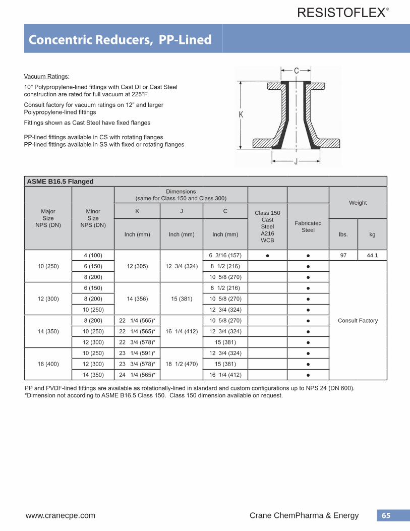
65www.cranecpe.com Crane ChemPharma & Energy
ASME B16.5 Flanged
Major Size
NPS (DN)
Minor Size
NPS (DN)
Dimensions(same for Class 150 and Class 300)
WeightK J C Class 150
CastSteelA216 WCB
FabricatedSteel
Inch (mm) Inch (mm) Inch (mm) lbs. kg
10 (250)
4 (100)
12 (305) 12 3/4 (324)
6 3/16 (157) ● ● 97 44.1
6 (150) 8 1/2 (216) ●
Consult Factory
8 (200) 10 5/8 (270) ●
12 (300)
6 (150)
14 (356) 15 (381)
8 1/2 (216) ●8 (200) 10 5/8 (270) ●
10 (250) 12 3/4 (324) ●
14 (350)
8 (200) 22 1/4 (565)*
16 1/4 (412)
10 5/8 (270) ●10 (250) 22 1/4 (565)* 12 3/4 (324) ●12 (300) 22 3/4 (578)* 15 (381) ●
16 (400)
10 (250) 23 1/4 (591)*
18 1/2 (470)
12 3/4 (324) ●12 (300) 23 3/4 (578)* 15 (381) ●14 (350) 24 1/4 (565)* 16 1/4 (412) ●
Concentric Reducers, PP-Lined
Vacuum Ratings:
10" Polypropylene-lined fittings with Cast DI or Cast Steel construction are rated for full vacuum at 225°F.
Consult factory for vacuum ratings on 12" and larger Polypropylene-lined fittings
Fittings shown as Cast Steel have fixed flanges
PP-lined fittings available in CS with rotating flangesPP-lined fittings available in SS with fixed or rotating flanges
PP and PVDF-lined fittings are available as rotationally-lined in standard and custom configurations up to NPS 24 (DN 600).*Dimension not according to ASME B16.5 Class 150. Class 150 dimension available on request.

66 Crane ChemPharma & Energy www.cranecpe.com
ASME B16.5 Class 150 Flanged
Major Size
NPS (DN)
Minor Size
NPS (DN)
Dimensions PP PVDF PFAWeight
K J C Cast SteelA216 WCBInch (mm) Inch (mm) Inch (mm) lbs. kg
1 1/2 (40) 1 (25) 4 1/2 (114) 2 7/8 (73) 2 (51) ● ● ● 6.5 3
2 (50)1 (25)
5 (127) 3 5/8 (92)2 (51) ● ● ● 9 4.1
1 1/2 (40) 2 7/8 (73) ● ● ● 11 5
3 (80)
1 (25)
6 (152) 5 (127)
2 (51) ● ● ● 14 6.4
1 1/2 (40) 2 7/8 (73) ● ● ● 15 6.8
2 (50) 3 5/8 (92) ● ● ● 17 7.7
4 (100)
1 (25)
7 (178) 6 3/16 (157)
2 (51) ● ● ● 22 10
1 1/2 (40) 2 7/8 (73) ● ● ● 25 11.4
2 (50) 3 5/8 (92) ● ● ● 27 12.3
3 (80) 5 (127) ● ● ● 33 15
6 (150)
1 (25)
9 (229) 8 1/2 (216)
2 (51) ● ● 36 16.4
1 1/2 (40) 2 7/8 (73) ● ● 42 19.1
2 (50) 3 5/8 (92) ● ● 42 19.1
3 (80) 5 (127) ● ● 44 20
4 (100) 6 3/16 (157) ● ● 52 23.6
8 (200)
1 (25)
11 (279) 10 5/8 (270)
2 (51) ● ● 46 20.9
2 (50) 3 5/8 (92) ● ● 63 28.6
3 (80) 5 (127) ● ● 70 31.8
4 (100) 6 3/16 (157) ● ● 83 37.7
6 (150) 8 1/2 (216) ● ● 80 36.4
Eccentric Reducers, PP / PVDF / PFA-Lined
PP and PVDF-lined fittings are available as rotationally-lined in standard and custom configurations up to NPS 24 (DN 600).
Vacuum Ratings:
1" - 8" PVDF-lined fittings are rated for full vacuum at 275°F.
1" - 12" Polypropylene-lined fittings with Cast DI or Cast Steel construction are rated for full vacuum at 225°F.
Consult factory for vacuum ratings on 14" and larger Polypropylene-lined fittings
Consult factory for vacuum ratings on PFA-lined fittings.
Fittings shown as Cast DI or Cast Steel have fixed flanges
PP/PVDF lined fittings available in CS with rotating flangesPP/PVDF lined fittings available in SS with fixed or rotating flanges
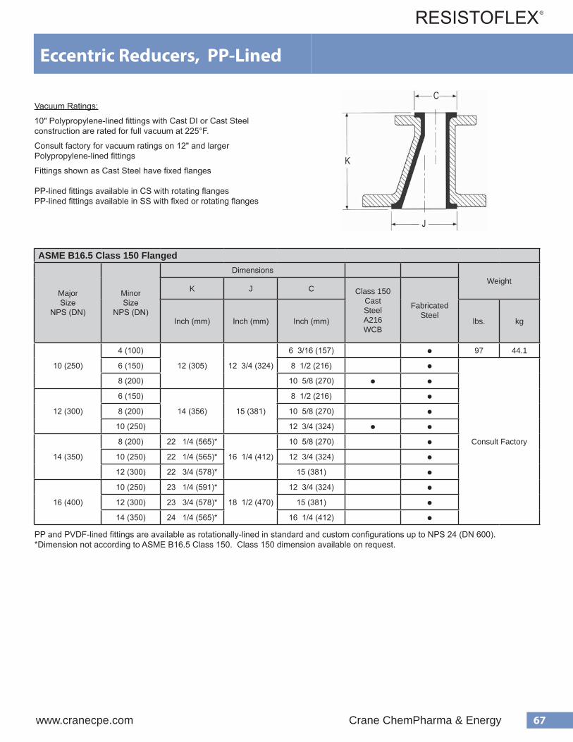
67www.cranecpe.com Crane ChemPharma & Energy
ASME B16.5 Class 150 Flanged
Major Size
NPS (DN)
Minor Size
NPS (DN)
DimensionsWeight
K J C Class 150 CastSteelA216 WCB
FabricatedSteel
Inch (mm) Inch (mm) Inch (mm) lbs. kg
10 (250)
4 (100)
12 (305) 12 3/4 (324)
6 3/16 (157) ● 97 44.1
6 (150) 8 1/2 (216) ●
Consult Factory
8 (200) 10 5/8 (270) ● ●
12 (300)
6 (150)
14 (356) 15 (381)
8 1/2 (216) ●8 (200) 10 5/8 (270) ●
10 (250) 12 3/4 (324) ● ●
14 (350)
8 (200) 22 1/4 (565)*
16 1/4 (412)
10 5/8 (270) ●10 (250) 22 1/4 (565)* 12 3/4 (324) ●12 (300) 22 3/4 (578)* 15 (381) ●
16 (400)
10 (250) 23 1/4 (591)*
18 1/2 (470)
12 3/4 (324) ●12 (300) 23 3/4 (578)* 15 (381) ●14 (350) 24 1/4 (565)* 16 1/4 (412) ●
Eccentric Reducers, PP-Lined
Vacuum Ratings:
10" Polypropylene-lined fittings with Cast DI or Cast Steel construction are rated for full vacuum at 225°F.
Consult factory for vacuum ratings on 12" and larger Polypropylene-lined fittings
Fittings shown as Cast Steel have fixed flanges
PP-lined fittings available in CS with rotating flangesPP-lined fittings available in SS with fixed or rotating flanges
PP and PVDF-lined fittings are available as rotationally-lined in standard and custom configurations up to NPS 24 (DN 600).*Dimension not according to ASME B16.5 Class 150. Class 150 dimension available on request.

68 Crane ChemPharma & Energy www.cranecpe.com
ASME B16.5 Class 150 Flanged
Major Size
NPS (DN)
Minor Size
NPS (DN)
Thickness,B
inch (mm)
H - Bolt Holes E - Bolt HolesBoltHole
RotationNo. SizeBolt
Circle Dia. Ginch (mm)
No. SizeBolt
Circle Dia. Dinch (mm)
DepthF
inch (mm)
1 (25)1/2 (15)
1 1/2 (38) 4 1/2-13 3 1/8 (79) 4 1/2-132 3/8 (67)
11/16 (17) 45o
3/4 (20) 2 3/4 (70)
1 1/2 (40) 1 (25) 1 1/2 (38) 4 1/2-13 3 7/8 (98) 4 1/2-13 3 1/8 (79) 9/16 (14) 45o
2 (50)1 (25)
1 1/2 (38) 4 5/8-11 4 3/4 (121) 4 1/2-133 1/8 (79) 9/16 (14) 0o
1 1/2 (40) 3 7/8 (98) 5/8 (16) 45o
3 (80)
1 (25)
1 1/2 (38) 4 5/8-11 6 (152) 41/2-13
3 1/8 (79) 9/16 (14)0o
1 1/2 (40) 3 7/8 (98) 5/8 (16)
2 (50) 5/8-11 4 3/4 (121) 3/4 (19) 45o
4 (100)
1 (25)2 (51)
83/4
7 1/2 (191) 4
1/2-133 1/8 (79) 9/16 (14)
0o1 1/2 (40) 3 7/8 (98) 5/8 (16)
2 (50)1 1/2 (38) 5/8-11
4 3/4 (121)3/4 (19)
3 (80) 5/8-11 6 (152)
6 (150)
1 1/2 (40)
2 (51)8
7/8
9 1/2 (241)4
1/2-13 3 7/8 (98) 9/16 (14)
0o2 (50)
3/4-10 5/8-11
4 3/4 (121) 5/8 (16)
3 (80) 6 (152)3/4 (19)
4 (100) 1 1/2 (38) 8 7 1/2 (191)
8 (200)
3 (802
87/8
11 3/4 (298)
45/8-11
6 (152)3/4 (19)
0o4 (100)8
7 1/2 (191)
6 (150) 1 1/2 (38) 3/4-10 3/4-10 9 1/2 (241) 13/16 (21)
10 (250)
4 (100)
2 (51) 121
14 1/4 (362) 8
5/8-11 7 1/2 (191) 3/4 (19)
0o6 (150)3/4-10
9 1/2 (241)13/16 (21)
8 (200) 7/8-9 11 3/4 (298)
12 (300)
6 (150)
2 (51)8 3/4-10
178 3/4-10
9 1/2 (241) 13/16 (21)
0o8 (200) 11 3/4 (298)1 1/4 (32)
10 (250) 12 7/8-9 12 7/8-9 14 1/4 (362)
Reducing Filler Flanges, PP / PVDF / PFA-LinedLiner Availability
PVDF: 1" - 8" (DN25 - DN200)PP: 1" - 12" (DN25 - DN400)PFA: 1" - 6" (DN25 - DN150)
Consult factory for size availability and dimensions of 14" - 16" with Polypropylene liner.
Straight-bore available on request
Available in carbon stee or stainless steel
Vacuum Ratings:
1" - 8" PVDF-lined fittings are rated for full vacuum at 275°F.
1" - 12" Polypropylene-lined fittings are rated for full vacuum at 225°F.
Consult factory for vacuum ratings on 14" and larger Polypropylene-lined fittings
Consult factory for vacuum ratings on PFA-lined fittings.
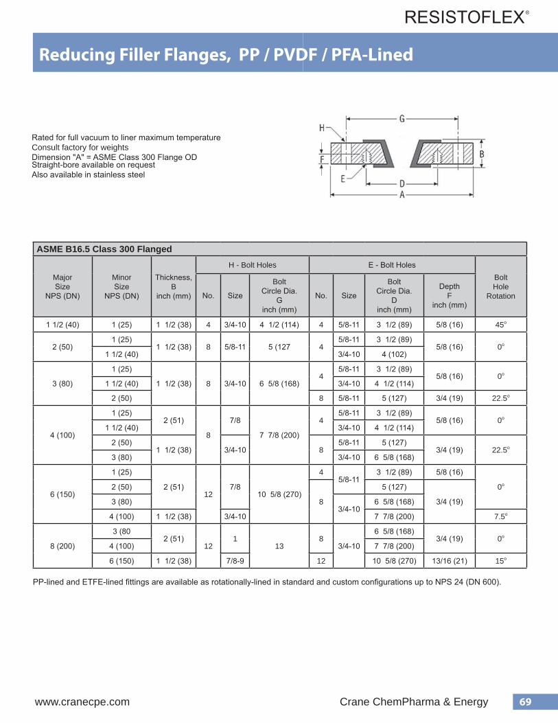
69www.cranecpe.com Crane ChemPharma & Energy
ASME B16.5 Class 300 Flanged
Major Size
NPS (DN)
Minor Size
NPS (DN)
Thickness,B
inch (mm)
H - Bolt Holes E - Bolt HolesBoltHole
RotationNo. Size
BoltCircle Dia.
Ginch (mm)
No. Size
BoltCircle Dia.
Dinch (mm)
DepthF
inch (mm)
1 1/2 (40) 1 (25) 1 1/2 (38) 4 3/4-10 4 1/2 (114) 4 5/8-11 3 1/2 (89) 5/8 (16) 45o
2 (50)1 (25)
1 1/2 (38) 8 5/8-11 5 (127 45/8-11 3 1/2 (89)
5/8 (16) 0o
1 1/2 (40) 3/4-10 4 (102)
3 (80)
1 (25)
1 1/2 (38) 8 3/4-10 6 5/8 (168)4
5/8-11 3 1/2 (89)5/8 (16) 0o
1 1/2 (40) 3/4-10 4 1/2 (114)
2 (50) 8 5/8-11 5 (127) 3/4 (19) 22.5o
4 (100)
1 (25)2 (51)
8
7/8
7 7/8 (200)
45/8-11 3 1/2 (89)
5/8 (16) 0o
1 1/2 (40) 3/4-10 4 1/2 (114)
2 (50)1 1/2 (38) 3/4-10 8
5/8-11 5 (127)3/4 (19) 22.5o
3 (80) 3/4-10 6 5/8 (168)
6 (150)
1 (25)
2 (51)12
7/810 5/8 (270)
45/8-11
3 1/2 (89) 5/8 (16)
0o2 (50)
8
5 (127)
3/4 (19)3 (80)3/4-10
6 5/8 (168)
4 (100) 1 1/2 (38) 3/4-10 7 7/8 (200) 7.5o
8 (200)
3 (802 (51)
121
138
3/4-10
6 5/8 (168)3/4 (19) 0o
4 (100) 7 7/8 (200)
6 (150) 1 1/2 (38) 7/8-9 12 10 5/8 (270) 13/16 (21) 15o
Reducing Filler Flanges, PP / PVDF / PFA-Lined
Rated for full vacuum to liner maximum temperatureConsult factory for weightsDimension "A" = ASME Class 300 Flange ODStraight-bore available on requestAlso available in stainless steel
PP-lined and ETFE-lined fittings are available as rotationally-lined in standard and custom configurations up to NPS 24 (DN 600).

70 Crane ChemPharma & Energy www.cranecpe.com
112
Fluoroflex-T (PTFE) Nozzle LinerThe non-adhesive characteristic of PTFE retards build-up of solids. When installed in the nozzleopening of reactors and other process equipment, the PTFE liner can be easily cleaned withoutdamaging fragile linings of expensive equipment. PTFE liners are designed to reduce transmis-sion of vibration or shock to flange faces of such equipment and the smooth, tough surface ofPTFE minimizes the effects of erosion. Liner is designed to fit inside Schedule 80 Pipe.
All dimensions in inches unless otherwise noted
" L" is expressed in inches with fractions of an inch in eighths, e.g., 36", 47 1/2", 62 5/8", etc.Length tolerance: To 36" ± 1/4", over 36" ± 1/2".
.oNtraP lanimoNeziSepiP
.D.OnoisnetxEebuT"A"
.aiDeralF"B"
ssenkcihTllaW"C"
L800-06391R 2/1 23/71 8/31
61/1
L210-06391R 4/3 46/54 61/111
L610-06391R 1 23/92 2
L420-06391R 2/11 23/511 8/72
L230-06391R 2 23/921 8/53
L840-06391R 3 23/722 5 46/5
L460-06391R 4 23/523 61/36 23/3
L690-06391R 6 46/545 2/18 46/7
L821-06391R 8 2/17 8/501 23/5
L061-0639R1 10 10 1/16 12 3/4 3/16
Size(NPS)
Size(DN)
Dimensions
A B C
inch mm inch mm inch mm
1/2 15 0.525 13 1 3/8 35 0.055 1.4
3/4 20 0.700 18 1 11/16 43 0.055 1.4
1 25 0.900 23 2 51 0.060 1.5
1 1/2 40 1.460 37 2 7/8 73 0.060 1.5
2 50 1.900 48 3 5/8 92 0.065 1.7
3 80 2.840 72 5 127 0.073 1.9
4 100 3.770 96 6 3/16 157 0.125 3.2
6 150 5.700 145 8 1/2 216 0.140 3.6
8 200 7.500 191 10 5/8 270 0.160 4.1
10 250 10.010 254 12 3/4 324 0.185 4.7
12 300 11.950 304 15 381 0.185 4.7
14 350 11.575 294 16 1/4 412 0.217 5.5
16* 400 14.055 357 18 1/2 470 0.256 6.5
18* 450 16.299 414 20 1/2 520 0.256 6.5
20* 500 17.480 444 23 585 0.256 6.5
24* 600 22.047 560 27 685 0.177 4.5
PTFE Nozzle Liners

71www.cranecpe.com Crane ChemPharma & Energy
113
Thermowell BafflesJacketed with PTFE
PTFE Jacketed Thermowell-baffles for inserting thermocouples below the liquid level of corrosion mixtures are designed towithstand immersion in all acids, except hydrofluoric, at temperatures to 350°F. Their corrosion resistance and strength are alsodesigned to provide long-life and maintenance-free operation of both thermowells and vessels. They are constructed of a PTFEjacketed steel pipe with a special tantalum bulb swaged on the bottom end. Heat conductivity of 0.130 cal./cm2/°C/sec. isprovided through the tantalum bulb, which combines good chemical resistance with high thermal conductivity.
*Thermowells have oversize O.D., which will not fit directly into standard size vessel nozzles. By selecting asmaller size pipe and a R60692 Special Reducing Flange, the correct fit can be achieved.**Recommended maximum length for mild agitation is shown as a general guide for liquids having about thesame density and viscosity as water. For longer lengths or more severe operating loads (density, viscosity andvelocity of fluid at the pipe), a larger size or internal bracing should be employed. Exceeding the maximumrecommended service temperature and/or pressure or maximum recommended unsupported length can result inpremature failure and possible personnel and equipment hazard.
Notes: Maximum Length = 10 ft.
ataDlanoisnemiD
#traP SPN egnalFeziS
laeSteksaG.aiD A lanimoN
*.D.O
dednemmoceR.xaM**htgneLdetroppusnU
.tF
L-80-A28291R 2/1 1 8/71 61/11 1 3
L-61-A28291R 1 2/11 4/32 61/31 23/511 4
L-42-A28291R 2/11 2 2/13 8/7 61/12 5
L-23-A28291R 2 3 8/34 61/11 61/92 6
Thermowell Ba�es
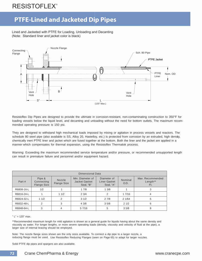
72 Crane ChemPharma & Energy www.cranecpe.com
Dip Pipes Lined and Jacketed with PTFE for Loading, Unloading & Decanting (Note: Standard liner and jacket color is black)
Resistoflex Dip Pipes are designed to provide the ultimate in corrosion-resistant, non-contaminating construction to 350°F for loading vessels below the liquid level, and decanting and unloading without the need for bottom outlets. The maximum recom- mended operating pressure is 150 psi.
They are designed to withstand high mechanical loads imposed by mixing or agitation in process vessels and reactors. The schedule 80 steel pipe (also available is SS, Alloy 20, Hastelloy, etc.) is protected from corrosion by an extruded, high densi ty, chemically inert PTFE liner and jacket which are fused together at the bottom. Both the liner and the jacket are applied in a manner which compensates for thermal expansion, using the Resistoflex Thermalok process.
Warning: Exceeding the maximum recommended service temperature and/or pressure, or recommended unsupported length can result in premature failure and personnel and/or equipment hazard.
4" - 20" dip pipes are available (manufactured by Resistoflex GmbH). Contact us for more information.
Use Resistoflex Reducing Flanges (seen on Page 65) to adapt for larger nozzles.
** Recommended maximum length for mild agitation is shown as a general guide for liquids having about the same density and viscosity as water. For longer lengths, or more severe operating loads (density, viscosity and velocity of fluid at the pipe), a larger size of internal bracing should be employed.
Note: The nozzle flange sizes shown are the only sizes available. To connect a dip pipe to a larger nozzle, a reducing flange must be used.
Solid PTFE dip pipes and spargers are also available.
" L" = 120" max.
a t a D l a n o i s n e m i D
# t r a P & e p i P
g n i t c e n n o C e z i S e g n a l F
e l z z o N e z i S e g n a l F
f o r e t e m a i D . n i M t e k s a G t e k c a J
l, "B"a e S
f o r e t e m a i D t e k s a G r e n i L
l, "A"a e S
l a n i m o N . D . O
d e d n e m m o c e R . x a M * * h t g n e L
. t F
L - 6 1 - 8 0 8 6 R 2 / 1 1 8 / 7 1 8 / 3 1 1 3
L - 4 2 - 6 1 8 6 R 1 2 / 1 1 4 / 3 2 2 6 1 / 7 1 4
L - 2 3 - 4 2 8 6 R 2 / 1 1 2 2 / 1 3 8 / 7 2 4 6 / 1 2 5
L - 8 4 - 2 3 8 6 R 2 3 8 / 3 4 8 / 5 3 2 / 1 2 6
L - 4 6 - 8 4 8 6 R 3 4 6 1 / 7 5 5 8 / 5 3 8
PTFE-Lined and Jacketed Dip Pipes
Lined and Jacketed with PTFE for Loading, Unloading and Decanting(Note: Standard liner and jacket color is black)
5"
B
A
L
Sch. 80 Pipe
Nozzle FlangeConnectingFlange
PTFE JacketPTFE Jacket
Nom. ODPTFE Liner
(120" Max.)
VentHole
VentHole

73www.cranecpe.com Crane ChemPharma & Energy
116
Spargers Lined and Jacketed with PTFE for Injecting Steam & Other Vapors.
Resistoflex Spargers for injecting steam and other vapors below the liquid level are designed to be highly resistant to mechani - cal fatigue and thermal shock, and provide the ultimate in corrosion-resistant, non-contaminating construction to 350°F.
Resistoflex Spargers use schedule 80 pipe, lined and jacketed with PTFE and are designed to withstand the high mechanicalloads associated with mixing or agitation in reactors or other process vessels. An external heavy wall PTFE tube is then applie d which extends beyond the weld of the lined and jacketed steel reinforcement to provide a sparging section at the bottom. A PTFE plug, held by PTFE bolts and nuts, is installed at the end of this heavy tube and minimizes corrosion deposits and its nonstick surface retards buildup of precipitated solids at the orfices. Good erosion resistance maintains contamination free service. Th e packing gland provides gas-tight seals up to 50 psi.
Warning: Exceeding the maximum recommended service temperature and/or pressure, or recommended unsupported length can result in premature failure and personnel and/or equipment hazard.
Note: The nozzle flange sizes shown are the only sizes available. To connect a sparger to a larger nozzle, a reducing flange must be used. Contact factory for more information as not all standard reducing flanges are suitable.
a t a D l a n o i s n e m i D
# t r a P & e p i P
g n i t c e n n o C e z i S e g n a l F
e l z z o N e z i S e g n a l F
l a n i m o N * . D . O
d e d n e m m o c e R . x a M * * h t g n e L d e t r o p p u s n U
. t F
X X - L - 2 3 6 1 7 6 R 1 2 6 1 / 5 1 1 4
X X - L - 8 4 4 2 76 R 2/ 1 1 3 6 1 / 9 2 5
X X - L - 4 6 4 2 7 6 R 2 / 1 1 4 4 6 / 3 3 2 5
X X - L - 4 6 2 3 7 6 R 2 4 3 6
X X - L - 6 9 8 4 7 6 R 3 6 8 / 1 4 8
X X - L - 4864 7 6 R 3 4 8 / 1 4 8
PTFE-Lined and Jacketed Spargers

74 Crane ChemPharma & Energy www.cranecpe.com
ASME B16.5 Class 150 Flanged
Major SizeNPS (DN)
Minor SizeNPS (DN)
DimensionsInch (mm)
ActualSmallest ID B K C
"H" Holes "E" Holes
No.of
HolesDia. D
(BCD)
No.of
HolesThrd. G
(BCD) Depth
1 (25) 1/2 (15) 13/32 (10) 1 5/8 (41) 2 (51) 1 3/8 (35) 4 5/8 (16) 3 1/8 (79) 4 1/2-13 2 3/8 (60) 7/8 (22)
1 (25) 3/4 (20) 5/8 (16) 1 5/8 (41) 2 (51) 1 11/16 (43) 4 5/8 (16) 3 1/8 (79) 4 1/2-13 2 3/4 (70) 7/8 (22)
1 1/2 (40) 1 (25) 1 1/8 (29) 1 9/16 (40) 2 7/8 (73) 2 (51) 4 5/8 (16) 3 7/8 (98) 4 1/2-13 3 1/8 (79) 7/8 (22)
2 (50) 1 (25) 1 1/8 (29) 1 9/16 (40) 3 5/8 (92) 2 (51) 4 3/4 (19) 4 3/4 (121) 4 1/2-13 3 1/8 (79) 7/8 (22)
2 (50) 1 1/2 (40) 1 5/8 (41) 1 9/16 (40) 3 5/8 (92) 2 7/8 (73) 4 3/4 (19) 4 3/4 (121) 4 1/2-13 3 7/8 (98) 7/8 (22)
2 1/2 (65) 2 (50) 2 1/8 (54) 1 9/16 (40) 4 1/8 (105) 3 5/8 (92) 4 3/4 (19) 5 1/2 (140) 4 5/8-11 4 3/4 (121) 7/8 (22)
3 (80) 1 (25) 1 1/8 (29) 1 5/8 (41) 5 (127) 2 (51) 4 3/4 (19) 6 (152) 4 1/2-13 3 1/8 (79) 3/4 (19)
3 (80) 1 1/2 (40) 1 5/8 (41) 1 5/8 (41) 5 (127) 2 7/8 (73) 4 3/4 (19) 6 (152) 4 1/2-13 3 7/8 (98) 7/8 (22)
3 (80) 2 (50) 2 1/8 (54) 1 3/4 (44) 5 (127) 3 5/8 (92) 4 3/4 (19) 6 (152) 4 5/8-11 4 3/4 (121) 7/8 (22)
3 (80) 2 1/2 (65) 2 3/16 (56) 1 5/8 (41) 5 (127) 4 1/8 (105) 4 3/4 (19) 6 (152) 4 5/8-11 5 1/2 (140) 7/8 (22)
4 (100) 1 (25) 1 1/8 (29) 1 7/8 (48) 6 3/16 (157) 2 (51) 8 3/4 (19) 7 1/2 (191) 4 1/2-13 3 1/8 (79) 11/16 (17)
4 (100) 1 1/2 (40) 1 5/8 (41) 1 5/8 (41) 6 3/16 (157) 2 7/8 (73) 8 3/4 (19) 7 1/2 (191) 4 1/2-13 3 7/8 (98) 7/8 (22)
4 (100) 2 (50) 2 1/8 (54) 2 (51) 6 3/16 (157) 3 5/8 (92) 8 3/4 (19) 7 1/2 (191) 4 5/8-11 4 3/4 (121) 7/8 (22)
4 (100) 3 (80) 2 25/32 (71) 1 3/4 (44) 6 3/16 (157) 5 (127) 8 3/4 (19) 7 1/2 (191) 4 5/8-11 6 (152) 7/8 (22)
5 (125) 4 (100) 3 3/4 (95) 1 5/8 (41) 7 5/16 (186) 6 3/16 (157) 8 7/8 (22) 8 1/2 (216) 8 5/8-11 7 1/2 (191) 1 (25)
6 (150) 1 1/2 (40) 1 5/8 (41) 1 7/8 (48) 8 1/2 (216) 2 7/8 (73) 8 7/8 (22) 9 1/2 (241) 4 1/2-13 3 7/8 (98) 11/16 (17)
6 (150) 2 (50) 2 1/8 (54) 1 7/8 (48) 8 1/2 (216) 3 5/8 (92) 8 7/8 (22) 9 1/2 (241) 4 5/8-11 4 3/4 (121) 3/4 (19)
6 (150) 3 (80) 2 31/32 (75) 1 3/4 (44) 8 1/2 (216) 5 (127) 8 7/8 (22) 9 1/2 (241) 4 5/8-11 6 (152) 1 (25)
6 (150) 4 (100) 3 3/4 (95) 2 1/8 (54) 8 1/2 (216) 6 3/16 (157) 8 7/8 (22) 9 1/2 (241) 8 5/8-11 7 1/2 (191) 7/8 (22)
6 (150) 5 (125) 4 25/32 (121) 1 3/4 (44) 8 1/2 (216) 7 5/16 (186) 8 7/8 (22) 9 1/2 (241) 8 3/4-10 8 1/2 (216) 1 (25)
8 (200) 4 (100) 3 29/32 (99) 2 (51) 10 5/8 (270) 6 3/16 (157) 8 7/8 (22) 11 3/4 (298) 8 5/8-11 7 1/2 (191) 7/8 (22)
8 (200) 6 (150) 5 25/32 (147) 2 (51) 10 5/8 (270) 8 1/2 (216) 8 7/8 (22) 11 3/4 (298) 8 3/4-10 9 1/2 (241) 1 1/8 (29)
10 (250) 4 (100) 4 1/16 (103) 2 7/16 (62) 12 3/4 (324) 6 3/16 (157) 12 1 (25) 14 1/4 (362) 8 5/8-11 7 1/2 (191) 7/8 (22)
10 (250) 6 (150) 5 29/32 (150) 2 7/16 (62) 12 3/4 (324) 8 1/2 (216) 12 1 (25) 14 1/4 (362) 8 3/4-10 9 1/2 (241) 1 (25)
10 (250) 8 (200) 7 11/16 (195) 2 7/16 (62) 12 3/4 (324) 10 5/8 (270) 12 1 (25) 14 1/4 (362) 8 3/4-10 11 3/4 (298) 1 (25)
35
Ductile Iron conforms to ASTM A395Consult factory for weightsConsult factory for bolt hole rotationDimension "A" = ASME Class 150 Flange OD
PTFE-Lined Reducing Flanges for Dip Pipes
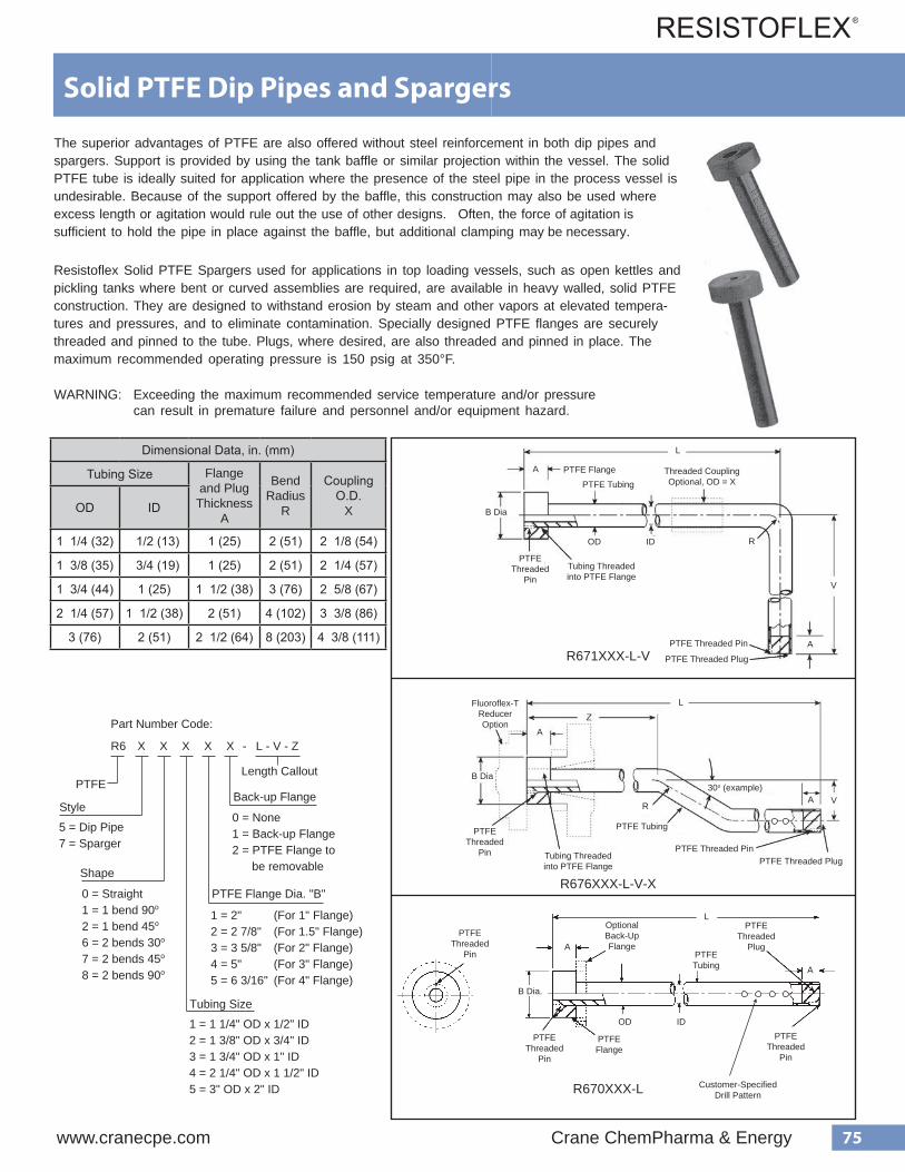
75www.cranecpe.com Crane ChemPharma & Energy
Solid PTFE Dip Pipes and Spargers
The superior advantages of PTFE are also offered without steel reinforcement in both dip pipes andspargers. Support is provided by using the tank baffle or similar projection within the vessel. The solidPTFE tube is ideally suited for application where the presence of the steel pipe in the process vessel isundesirable. Because of the support offered by the baffle, this construction may also be used whereexcess length or agitation would rule out the use of other designs. Often, the force of agitation issufficient to hold the pipe in place against the baffle, but additional clamping may be necessary.
Resistoflex Solid PTFE Spargers used for applications in top loading vessels, such as open kettles andpickling tanks where bent or curved assemblies are required, are available in heavy walled, solid PTFEconstruction. They are designed to withstand erosion by steam and other vapors at elevated tempera-tures and pressures, and to eliminate contamination. Specially designed PTFE flanges are securelythreaded and pinned to the tube. Plugs, where desired, are also threaded and pinned in place. Themaximum recommended operating pressure is 150 psig at 350°F.
WARNING: Exceeding the maximum recommended service temperature and/or pressure can result in premature failure and personnel and/or equipment hazard.
R671XXX-L-V
R676XXX-L-V-X
R670XXX-L
PTFEThreaded
PinA
B Dia.
PTFEThreaded
Pin
PTFEFlange
Customer-SpecifiedDrill Pattern
OD ID
PTFETubing A
OptionalBack-Up Flange
PTFEThreaded
Pin
PTFEThreaded
Plug
R6
Part Number Code:
X X X X X - L - V - Z
PTFE
Style
0 = Straight1 = 1 bend 90o
2 = 1 bend 45o
6 = 2 bends 30o
7 = 2 bends 45o
8 = 2 bends 90o
5 = Dip Pipe7 = Sparger
Shape
Tubing Size
PTFE Flange Dia. "B"
Back-up Flange
0 = None1 = Back-up Flange2 = PTFE Flange to be removable
1 = 1 1/4" OD x 1/2" ID2 = 1 3/8" OD x 3/4" ID3 = 1 3/4" OD x 1" ID4 = 2 1/4" OD x 1 1/2" ID5 = 3" OD x 2" ID
1 = 2" (For 1" Flange)2 = 2 7/8" (For 1.5" Flange)3 = 3 5/8" (For 2" Flange)4 = 5" (For 3" Flange)5 = 6 3/16" (For 4" Flange)
Length Callout
PTFE Threaded Plug
30o (example)
Tubing Threaded into PTFE Flange
Tubing Threaded into PTFE Flange
PTFE Threaded Pin
PTFE Threaded Plug
PTFE Threaded Pin
PTFE Tubing
PTFE Tubing
OD ID
PTFE Flange
R V
V
L
L
L
A
A
A
A
B Dia
B Dia
PTFE Threaded
Pin
PTFE Threaded
Pin
Fluoroflex-TReducerOption
Threaded CouplingOptional, OD = X
R
Dimensional Data, in. (mm)
Tubing Size Flange and Plug Thickness
A
Bend Radius
R
Coupling O.D.
XOD ID
1 1/4 (32) 1/2 (13) 1 (25) 2 (51) 2 1/8 (54)
1 3/8 (35) 3/4 (19) 1 (25) 2 (51) 2 1/4 (57)
1 3/4 (44) 1 (25) 1 1/2 (38) 3 (76) 2 5/8 (67)
2 1/4 (57) 1 1/2 (38) 2 (51) 4 (102) 3 3/8 (86)
3 (76) 2 (51) 2 1/2 (64) 8 (203) 4 3/8 (111)
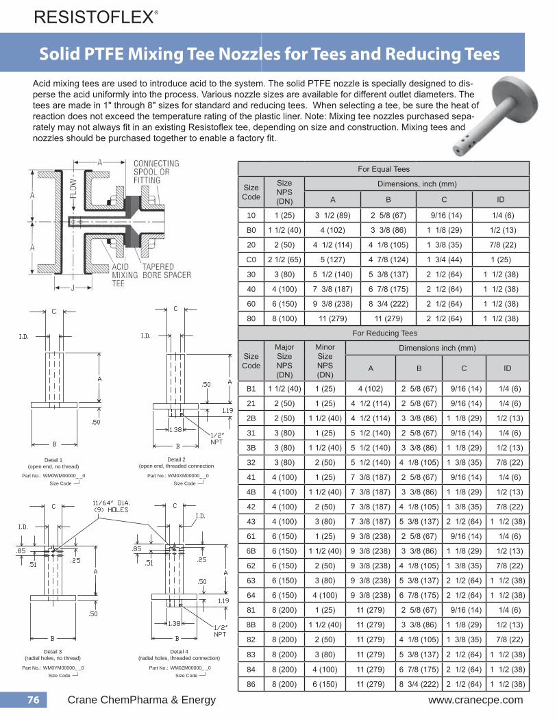
76 Crane ChemPharma & Energy www.cranecpe.com
Solid PTFE Mixing Tee Nozzles for Tees and Reducing TeesMixing Tee Nozzles Acid mixing tees are used to introduce acid to the system. The solid PTFE nozzle is specially designed to disperse the acid uniformly into the process. Various nozzle sizes are available for different outlet diameters. Optional open-ended constructions are also available. The tees are made in 1" through 8" sizes for standard and reducing tees, and are available on special request. The PTFE mixing nozzle is also used with plastic lined tees. When selecting a tee, be sure the heat of reaction does not exceed the temperature rating of the plastic liner.
Note: Mixing tee nozzles purchased separately may not always fit in an existing Resistoflex tee, depending on size and construction. Mixing tees and nozzles should be purchased together to enable a factory fit.
Detail 1 Detail 2 Detail 3 Detail 4 WM0WM00000_ _0 WM0XM00000_ _0 WM0YM00000_ _0 WM0ZM00000_ _0Part No.:
Size Code
Detail 1(open end, no thread)
Detail 2(open end, threaded connection
Detail 3(radial holes, no thread)
Detail 4(radial holes, threaded connection)
WM0WM00000_ _0 WM0XM00000_ _0 WM0YM00000_ _0 WM0ZM00000_ _0Part No.: Part No.:Size Code Size Code
Part No.:Size Code
Part No.:Size Code
Acid mixing tees are used to introduce acid to the system. The solid PTFE nozzle is specially designed to dis-perse the acid uniformly into the process. Various nozzle sizes are available for different outlet diameters. The tees are made in 1" through 8" sizes for standard and reducing tees. When selecting a tee, be sure the heat of reaction does not exceed the temperature rating of the plastic liner. Note: Mixing tee nozzles purchased sepa-rately may not always fit in an existing Resistoflex tee, depending on size and construction. Mixing tees and nozzles should be purchased together to enable a factory fit.
For Reducing Tees
SizeCode
MajorSizeNPS(DN)
MinorSizeNPS(DN)
Dimensions inch (mm)
A B C ID
B1 1 1/2 (40) 1 (25) 4 (102) 2 5/8 (67) 9/16 (14) 1/4 (6)
21 2 (50) 1 (25) 4 1/2 (114) 2 5/8 (67) 9/16 (14) 1/4 (6)
2B 2 (50) 1 1/2 (40) 4 1/2 (114) 3 3/8 (86) 1 1/8 (29) 1/2 (13)
31 3 (80) 1 (25) 5 1/2 (140) 2 5/8 (67) 9/16 (14) 1/4 (6)
3B 3 (80) 1 1/2 (40) 5 1/2 (140) 3 3/8 (86) 1 1/8 (29) 1/2 (13)
32 3 (80) 2 (50) 5 1/2 (140) 4 1/8 (105) 1 3/8 (35) 7/8 (22)
41 4 (100) 1 (25) 7 3/8 (187) 2 5/8 (67) 9/16 (14) 1/4 (6)
4B 4 (100) 1 1/2 (40) 7 3/8 (187) 3 3/8 (86) 1 1/8 (29) 1/2 (13)
42 4 (100) 2 (50) 7 3/8 (187) 4 1/8 (105) 1 3/8 (35) 7/8 (22)
43 4 (100) 3 (80) 7 3/8 (187) 5 3/8 (137) 2 1/2 (64) 1 1/2 (38)
61 6 (150) 1 (25) 9 3/8 (238) 2 5/8 (67) 9/16 (14) 1/4 (6)
6B 6 (150) 1 1/2 (40) 9 3/8 (238) 3 3/8 (86) 1 1/8 (29) 1/2 (13)
62 6 (150) 2 (50) 9 3/8 (238) 4 1/8 (105) 1 3/8 (35) 7/8 (22)
63 6 (150) 3 (80) 9 3/8 (238) 5 3/8 (137) 2 1/2 (64) 1 1/2 (38)
64 6 (150) 4 (100) 9 3/8 (238) 6 7/8 (175) 2 1/2 (64) 1 1/2 (38)
81 8 (200) 1 (25) 11 (279) 2 5/8 (67) 9/16 (14) 1/4 (6)
8B 8 (200) 1 1/2 (40) 11 (279) 3 3/8 (86) 1 1/8 (29) 1/2 (13)
82 8 (200) 2 (50) 11 (279) 4 1/8 (105) 1 3/8 (35) 7/8 (22)
83 8 (200) 3 (80) 11 (279) 5 3/8 (137) 2 1/2 (64) 1 1/2 (38)
84 8 (200) 4 (100) 11 (279) 6 7/8 (175) 2 1/2 (64) 1 1/2 (38)
86 8 (200) 6 (150) 11 (279) 8 3/4 (222) 2 1/2 (64) 1 1/2 (38)
Detail 1(open end, no thread)
Detail 2(open end, threaded connection
Detail 3(radial holes, no thread)
Detail 4(radial holes, threaded connection)
WM0WM00000_ _0 WM0XM00000_ _0 WM0YM00000_ _0 WM0ZM00000_ _0Part No.: Part No.:Size Code Size Code
Part No.:Size Code
Part No.:Size Code
For Equal Tees
SizeCode
SizeNPS (DN)
Dimensions, inch (mm)
A B C ID
10 1 (25) 3 1/2 (89) 2 5/8 (67) 9/16 (14) 1/4 (6)
B0 1 1/2 (40) 4 (102) 3 3/8 (86) 1 1/8 (29) 1/2 (13)
20 2 (50) 4 1/2 (114) 4 1/8 (105) 1 3/8 (35) 7/8 (22)
C0 2 1/2 (65) 5 (127) 4 7/8 (124) 1 3/4 (44) 1 (25)
30 3 (80) 5 1/2 (140) 5 3/8 (137) 2 1/2 (64) 1 1/2 (38)
40 4 (100) 7 3/8 (187) 6 7/8 (175) 2 1/2 (64) 1 1/2 (38)
60 6 (150) 9 3/8 (238) 8 3/4 (222) 2 1/2 (64) 1 1/2 (38)
80 8 (100) 11 (279) 11 (279) 2 1/2 (64) 1 1/2 (38)
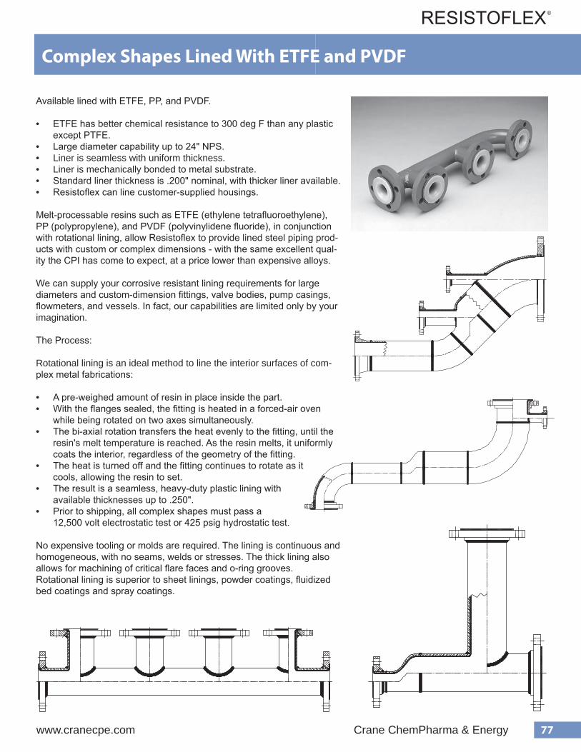
77www.cranecpe.com Crane ChemPharma & Energy
For Reducing Tees
SizeCode
MajorSizeNPS(DN)
MinorSizeNPS(DN)
Dimensions inch (mm)
A B C ID
B1 1 1/2 (40) 1 (25) 4 (102) 2 5/8 (67) 9/16 (14) 1/4 (6)
21 2 (50) 1 (25) 4 1/2 (114) 2 5/8 (67) 9/16 (14) 1/4 (6)
2B 2 (50) 1 1/2 (40) 4 1/2 (114) 3 3/8 (86) 1 1/8 (29) 1/2 (13)
31 3 (80) 1 (25) 5 1/2 (140) 2 5/8 (67) 9/16 (14) 1/4 (6)
3B 3 (80) 1 1/2 (40) 5 1/2 (140) 3 3/8 (86) 1 1/8 (29) 1/2 (13)
32 3 (80) 2 (50) 5 1/2 (140) 4 1/8 (105) 1 3/8 (35) 7/8 (22)
41 4 (100) 1 (25) 7 3/8 (187) 2 5/8 (67) 9/16 (14) 1/4 (6)
4B 4 (100) 1 1/2 (40) 7 3/8 (187) 3 3/8 (86) 1 1/8 (29) 1/2 (13)
42 4 (100) 2 (50) 7 3/8 (187) 4 1/8 (105) 1 3/8 (35) 7/8 (22)
43 4 (100) 3 (80) 7 3/8 (187) 5 3/8 (137) 2 1/2 (64) 1 1/2 (38)
61 6 (150) 1 (25) 9 3/8 (238) 2 5/8 (67) 9/16 (14) 1/4 (6)
6B 6 (150) 1 1/2 (40) 9 3/8 (238) 3 3/8 (86) 1 1/8 (29) 1/2 (13)
62 6 (150) 2 (50) 9 3/8 (238) 4 1/8 (105) 1 3/8 (35) 7/8 (22)
63 6 (150) 3 (80) 9 3/8 (238) 5 3/8 (137) 2 1/2 (64) 1 1/2 (38)
64 6 (150) 4 (100) 9 3/8 (238) 6 7/8 (175) 2 1/2 (64) 1 1/2 (38)
81 8 (200) 1 (25) 11 (279) 2 5/8 (67) 9/16 (14) 1/4 (6)
8B 8 (200) 1 1/2 (40) 11 (279) 3 3/8 (86) 1 1/8 (29) 1/2 (13)
82 8 (200) 2 (50) 11 (279) 4 1/8 (105) 1 3/8 (35) 7/8 (22)
83 8 (200) 3 (80) 11 (279) 5 3/8 (137) 2 1/2 (64) 1 1/2 (38)
84 8 (200) 4 (100) 11 (279) 6 7/8 (175) 2 1/2 (64) 1 1/2 (38)
86 8 (200) 6 (150) 11 (279) 8 3/4 (222) 2 1/2 (64) 1 1/2 (38)
Complex Shapes Lined With ETFE and PVDF
Available lined with ETFE, PP, and PVDF.
• ETFE has better chemical resistance to 300 deg F than any plastic except PTFE.
• Large diameter capability up to 24" NPS.• Liner is seamless with uniform thickness.• Liner is mechanically bonded to metal substrate.• Standard liner thickness is .200" nominal, with thicker liner available.• Resistoflex can line customer-supplied housings.
Melt-processable resins such as ETFE (ethylene tetrafluoroethylene), PP (polypropylene), and PVDF (polyvinylidene fluoride), in conjunction with rotational lining, allow Resistoflex to provide lined steel piping prod-ucts with custom or complex dimensions - with the same excellent qual-ity the CPI has come to expect, at a price lower than expensive alloys.
We can supply your corrosive resistant lining requirements for large diameters and custom-dimension fittings, valve bodies, pump casings, flowmeters, and vessels. In fact, our capabilities are limited only by your imagination.
The Process:
Rotational lining is an ideal method to line the interior surfaces of com-plex metal fabrications:
• A pre-weighed amount of resin in place inside the part.• With the flanges sealed, the fitting is heated in a forced-air oven
while being rotated on two axes simultaneously.• The bi-axial rotation transfers the heat evenly to the fitting, until the
resin's melt temperature is reached. As the resin melts, it uniformly coats the interior, regardless of the geometry of the fitting.
• The heat is turned off and the fitting continues to rotate as it cools, allowing the resin to set.
• The result is a seamless, heavy-duty plastic lining with available thicknesses up to .250".
• Prior to shipping, all complex shapes must pass a 12,500 volt electrostatic test or 425 psig hydrostatic test.
No expensive tooling or molds are required. The lining is continuous and homogeneous, with no seams, welds or stresses. The thick lining also allows for machining of critical flare faces and o-ring grooves.Rotational lining is superior to sheet linings, powder coatings, fluidized bed coatings and spray coatings.
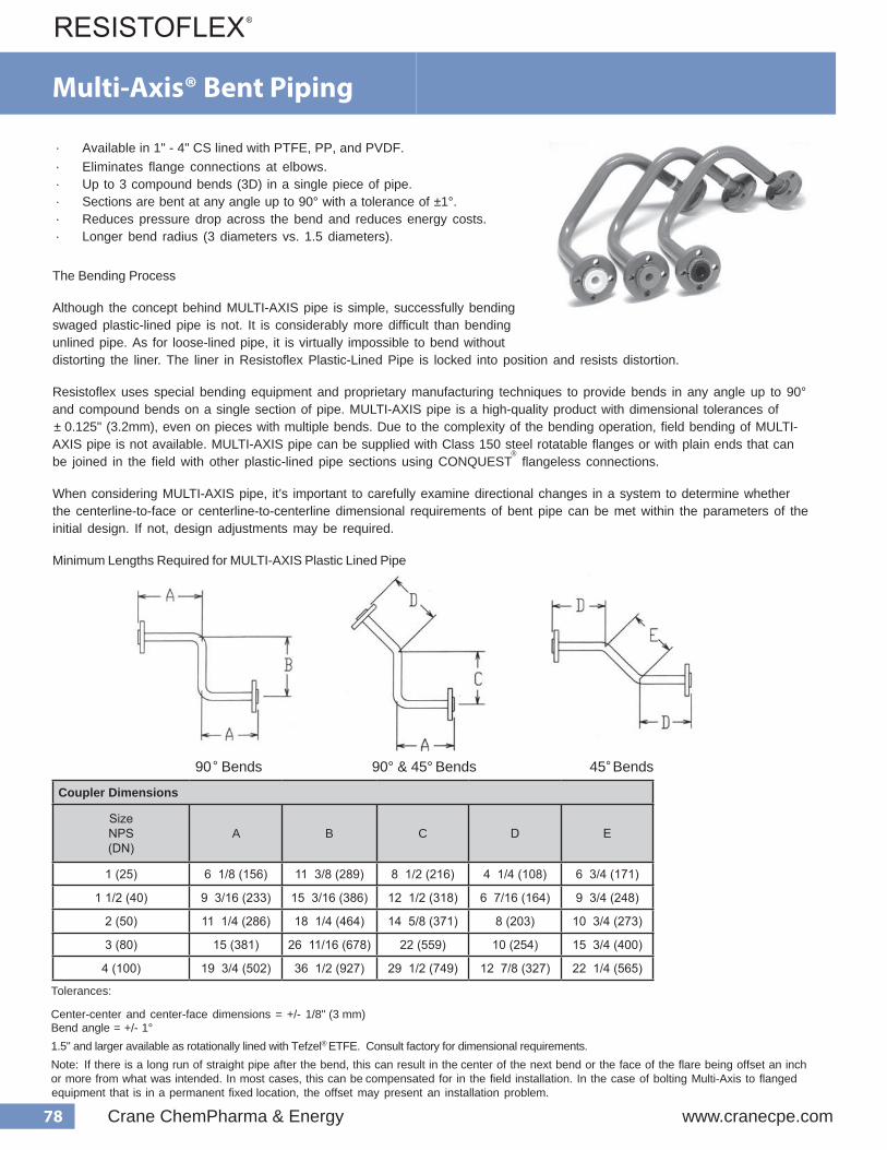
78 Crane ChemPharma & Energy www.cranecpe.com
MULTI-AXIS ®
· Eliminates flange connections at elbows.· Available in 1" - 4" CS lined with PTFE, PP, and PVDF.
· Up to 3 compound bends (3D) in a single piece of pipe.· Sections are bent at any angle up to 90° with a tolerance of ±1°.· Reduces pressure drop across the bend and reduces energy costs.· Longer bend radius (3 diameters vs. 1.5 diameters).
The Bending Process
Although the concept behind MULTI-AXIS pipe is simple, successfully bending swaged plastic-lined pipe is not. It is considerably more difficult than bending unlined pipe. As for loose-lined pipe, it is virtually impossible to bend without distorting the liner. The liner in Resistoflex Plastic-Lined Pipe is locked into position and resists distortion.
Resistoflex uses special bending equipment and proprietary manufacturing techniques to provide bends in any angle up to 90° and compound bends on a single section of pipe. MULTI-AXIS pipe is a high-quality product with dimensional tolerances of ± 0.125" (3.2mm), even on pieces with multiple bends. Due to the complexity of the bending operation, field bending of MULTI- AXIS pipe is not available. MULTI-AXIS pipe can be supplied with Class 150 steel rotatable flanges or with plain ends that can be joined in the field with other plastic-lined pipe sections using CONQUEST
® flangeless connections.
When considering MULTI-AXIS pipe, it’s important to carefully examine directional changes in a system to determine whether the centerline-to-face or centerline-to-centerline dimensional requirements of bent pipe can be met within the parameters of the initial design. If not, design adjustments may be required.
Minimum Lengths Required for MULTI-AXIS Plastic Lined Pipe
°90 Bends 90° & 45° Bends 45° Bends
Tolerances:
1.5" and larger available as rotationally lined with Tefzel® ETFE. Consult factory for dimensional requirements.
Center-center and center-face dimensions = +/- 1/8" (3 mm)Bend angle = +/- 1°
Note: If there is a long run of straight pipe after the bend, this can result in theor more from what was intended. In most cases, this can be
center of the next bend or the face of the flare being offset an inchcompensated for in the field installation. In the case of bolting Multi-Axis to flanged
equipment that is in a permanent fixed location, the offset may present an installation problem.
Multi-Axis® Bent Piping
Coupler Dimensions
SizeNPS(DN)
A B C D E
1 (25) 6 1/8 (156) 11 3/8 (289) 8 1/2 (216) 4 1/4 (108) 6 3/4 (171)
1 1/2 (40) 9 3/16 (233) 15 3/16 (386) 12 1/2 (318) 6 7/16 (164) 9 3/4 (248)
2 (50) 11 1/4 (286) 18 1/4 (464) 14 5/8 (371) 8 (203) 10 3/4 (273)
3 (80) 15 (381) 26 11/16 (678) 22 (559) 10 (254) 15 3/4 (400)
4 (100) 19 3/4 (502) 36 1/2 (927) 29 1/2 (749) 12 7/8 (327) 22 1/4 (565)
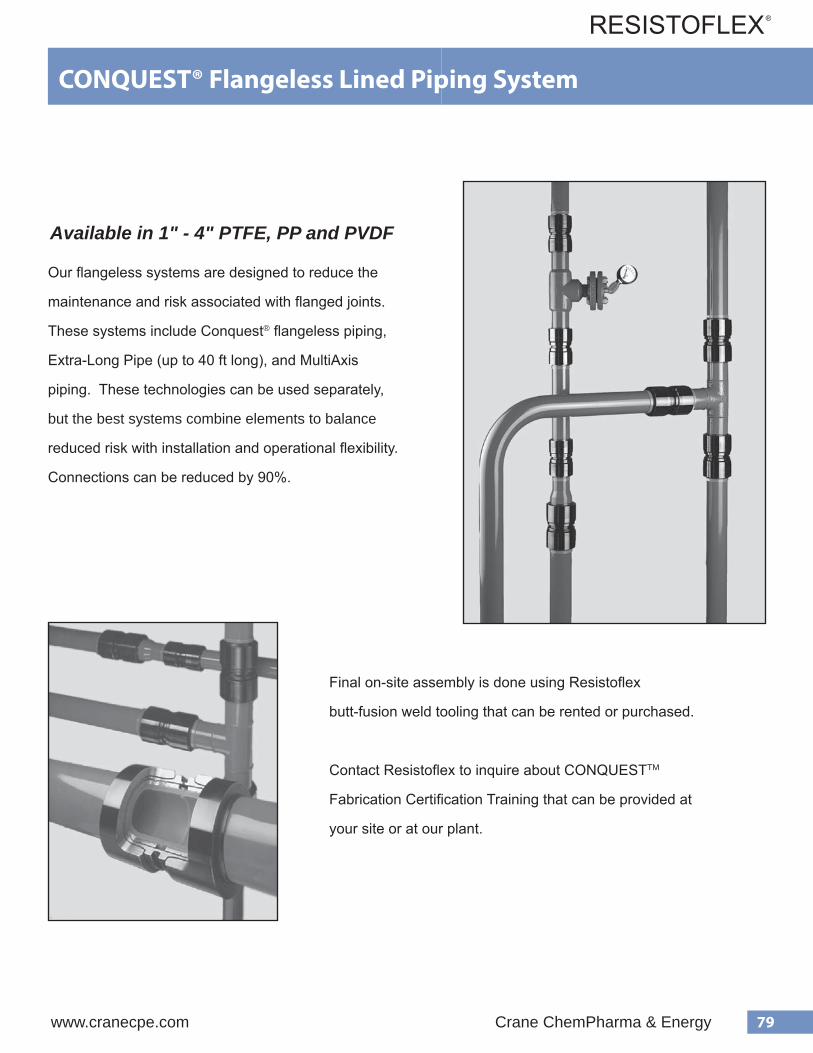
79www.cranecpe.com Crane ChemPharma & Energy
CONQUEST® Flangeless Lined Piping System
Available in 1" - 4" PTFE, PP and PVDF
Our flangeless systems are designed to reduce the
maintenance and risk associated with flanged joints.
These systems include Conquest® flangeless piping,
Extra-Long Pipe (up to 40 ft long), and MultiAxis
piping. These technologies can be used separately,
but the best systems combine elements to balance
reduced risk with installation and operational flexibility.
Connections can be reduced by 90%.
Final on-site assembly is done using Resistoflex
butt-fusion weld tooling that can be rented or purchased.
Contact Resistoflex to inquire about CONQUESTTM
Fabrication Certification Training that can be provided at
your site or at our plant.
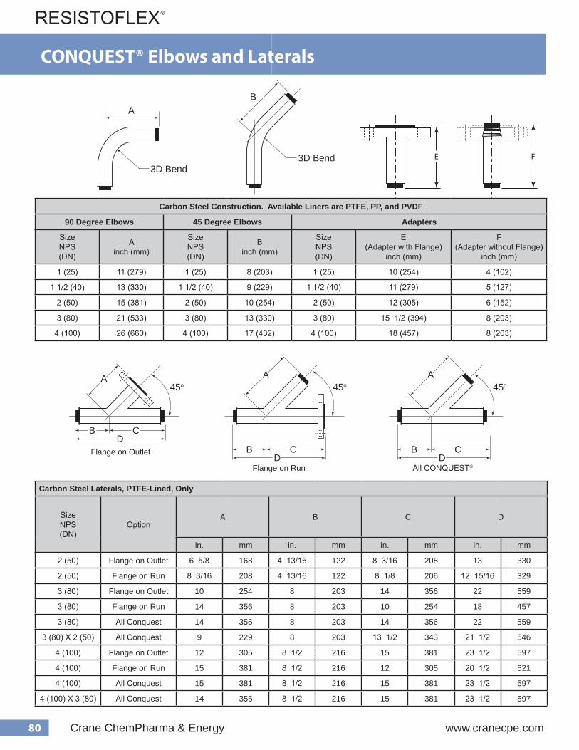
80 Crane ChemPharma & Energy www.cranecpe.com
CONQUEST® Elbows and Laterals
Carbon Steel Laterals, PTFE-Lined, Only
SizeNPS(DN)
OptionA B C D
in. mm in. mm in. mm in. mm
2 (50) Flange on Outlet 6 5/8 168 4 13/16 122 8 3/16 208 13 330
2 (50) Flange on Run 8 3/16 208 4 13/16 122 8 1/8 206 12 15/16 329
3 (80) Flange on Outlet 10 254 8 203 14 356 22 559
3 (80) Flange on Run 14 356 8 203 10 254 18 457
3 (80) All Conquest 14 356 8 203 14 356 22 559
3 (80) X 2 (50) All Conquest 9 229 8 203 13 1/2 343 21 1/2 546
4 (100) Flange on Outlet 12 305 8 1/2 216 15 381 23 1/2 597
4 (100) Flange on Run 15 381 8 1/2 216 12 305 20 1/2 521
4 (100) All Conquest 15 381 8 1/2 216 15 381 23 1/2 597
4 (100) X 3 (80) All Conquest 14 356 8 1/2 216 15 381 23 1/2 597
Carbon Steel Construction. Available Liners are PTFE, PP, and PVDF
90 Degree Elbows 45 Degree Elbows Adapters
SizeNPS(DN)
Ainch (mm)
SizeNPS(DN)
Binch (mm)
SizeNPS(DN)
E(Adapter with Flange)
inch (mm)
F(Adapter without Flange)
inch (mm)
1 (25) 11 (279) 1 (25) 8 (203) 1 (25) 10 (254) 4 (102)
1 1/2 (40) 13 (330) 1 1/2 (40) 9 (229) 1 1/2 (40) 11 (279) 5 (127)
2 (50) 15 (381) 2 (50) 10 (254) 2 (50) 12 (305) 6 (152)
3 (80) 21 (533) 3 (80) 13 (330) 3 (80) 15 1/2 (394) 8 (203)
4 (100) 26 (660) 4 (100) 17 (432) 4 (100) 18 (457) 8 (203)
0°
A
45o
B
3D Bend
3D Bend
45o45o
B CD
A
B CD
A
B CD
A
0°
A
45o
B
3D Bend
3D Bend
45o45o
B CD
A
B CD
A
B CD
A
E FE F
0°
A
45o
B
3D Bend
3D Bend
45o45o
B CD
A
B CD
A
B CD
A
Flange on Outlet
Flange on Run All CONQUEST®

81www.cranecpe.com Crane ChemPharma & Energy
All Conquest Flange on Run Flange on Outlet or
Instrument Tee
Flanged on Both Ends
45o
G
G G
D
A
H H
G H G G H
Carbon Steel Tees
SizeNPS(DN)
OptionAvailable Liner G H
PTFE PP PVDF in. mm in. mm
1 (25)
All Conquest ● ● ●
5 1/2 140 3 1/2 89Flange on Stack ● ● ●
Flange on Run ● ● ●
Flange on Run and Outlet ● ● ●
1 1/2 (40)
All Conquest ● ● ●
6 152 4 102Flange on Stack ● ● ●
Flange on Run ● ● ●
Flange on Run and Outlet ● ● ●
2 (50)
All Conquest ● ● ●
6 1/2 165 4 1/2 114Flange on Stack ● ● ●
Flange on Run ● ● ●
Flange on Run and Outlet ● ● ●
3 (80)
All Conquest ● ● ●
7 1/2 191 5 1/2 140Flange on Stack ● ● ●
Flange on Run ● ● ●
Flange on Run and Outlet ● ● ●
3 (80) x 2 (50)All Conquest ●
7 1/2 191 5 1/2 140Flange on Stack ●
4 (100)
All Conquest ● ● ●
9 1/2 241 6 1/2 165Flange on Stack ● ● ●
Flange on Run ● ● ●
Flange on Run and Outlet ● ● ●
4 (100) x 3 (80)All Conquest ●
9 1/2 241 6 1/2 165Flange on Stack ●
Flange on OutletFlange on RunAll CONQUEST® Flange on Run and Outlet
CONQUEST® Tees and Reducing Tees
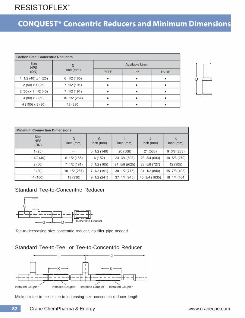
82 Crane ChemPharma & Energy www.cranecpe.com
CONQUEST® Concentric Reducers and Minimum Dimensions
Carbon Steel Concentric Reducers
SizeNPS(DN)
Dinch (mm)
Available Liner
PTFE PP PVDF
1 1/2 (40) x 1 (25) 6 1/2 (165) ● ● ●
2 (50) x 1 (25) 7 1/2 (191) ● ● ●
2 (50) x 1 1/2 (40) 7 1/2 (191) ● ● ●
3 (80) x 2 (50) 10 1/2 (267) ● ● ●
4 (100) x 3 (80) 13 (330) ● ● ●
71
Concentric Reducers
Standard Tee-to-Concentric Reducer
Standard Tee-to-Tee, or Tee-to-Concentric Reducer
Tee-to-decreasing size concentric reducer, no filler pipe needed.
Minimum tee-to-tee or tee-to-increasing size concentric reducer length.
. a i D g n i t t i F ) m m ( . n i
D ) m m ( . n i E F T P F D V P P P t h g i e W
) g k ( . s b l
1 x 5 . 1 ) 5 2 x 0 4 ( ) 5 6 1 ( 5 . 6 0 1 B 0 0 W W 3 M 0 0 0 6 0 1 B 0 0 W W 3 K 0 0 0 6 0 1 B 0 0 W W 3 P 0 0 0 6 ) 2 . 3 ( 7
1 x 2 ) 5 2 x 0 5 ( ) 1 9 1 ( 5 . 7 0 1 2 0 0 W W 3 M 0 0 0 6 0 1 2 0 0 W W 3 K 0 0 0 6 0 1 2 0 0 W W 3 P 0 0 0 6 ) 2 . 3 ( 7
2 / 1 1 x 2 ) 0 4 x 0 5 ( ) 1 9 1 ( 5 . 7 0 B 2 0 0 W W 3 M 0 0 0 6 0 B 2 0 0 W W 3 K 0 0 0 6 0 B 2 0 0 W W 3 P 0 0 0 6 ) 2 . 3 ( 7
2 x 3 ) 0 5 x 0 8 ( ) 7 6 2 ( 5 . 0 1 0 2 3 0 0 W W 3 M 0 0 0 6 0 2 3 0 0 W W 3 K 0 0 0 6 0 2 3 0 0 W W 3 P 0 0 0 6 ) 4 . 6 ( 4 1
3 x 4 ) 0 8 x 0 0 1 ( ) 0 3 3 ( 3 1 0 3 4 0 0 W W 3 M 0 0 0 6 0 3 4 0 0 W W 3 K 0 0 0 6 0 3 4 0 0 W W 3 P 0 0 0 6 ) 6 . 3 1 ( 0 3
. a i D g n i t t i F ) m m ( . n i
I ) m m ( . n i
J ) m m ( . n i
K ) m m ( . n i
) 5 2 ( 1 0 2 ) 8 0 5 (
1 2 ) 3 3 5 (
8 / 3 9 ) 8 3 2 (
) 0 4 ( 5 . 1 4 / 3 3 2 ) 3 0 6 (
4 / 3 3 2 ) 3 0 6 (
8 / 5 0 1 ) 0 7 2 (
) 0 5 ( 2 8 / 5 4 2 ) 5 2 6 (
8 / 5 8 2 ) 7 2 7 (
2 1 ) 5 0 3 (
) 0 8 ( 3 2 / 1 0 3 ) 5 7 7 (
2 / 1 1 3 ) 0 0 8 (
8 / 7 5 1 ) 3 0 4 (
) 0 0 1 ( 4 4 / 1 7 3 ) 6 4 9 (
4 / 3 0 4 ) 5 3 0 1 (
4 / 1 8 1 ) 4 6 4 (
D Uninstalled Coupler
Installed Coupler Installed Coupler
G
G
K
I J
K
Installed Coupler Installed Coupler
Minimum Connection Dimensions
SizeNPS(DN)
Dinch (mm)
Ginch (mm)
Iinch (mm)
Jinch (mm)
Kinch (mm)
1 (25) - - 5 1/2 (140) 20 (508) 21 (533) 9 3/8 (238)
1 1/2 (40) 6 1/2 (165) 6 (152) 23 3/4 (603) 23 3/4 (603) 10 5/8 (270)
2 (50) 7 1/2 (191) 6 1/2 (165) 24 5/8 ((625) 28 5/8 (727) 12 (305)
3 (80) 10 1/2 (267) 7 1/2 (191) 30 1/2 (775) 31 1/2 (800) 15 7/8 (403)
4 (100) 13 (330) 9 1/2 (241) 37 1/4 (945) 40 3/4 (1035) 18 1/4 (464)
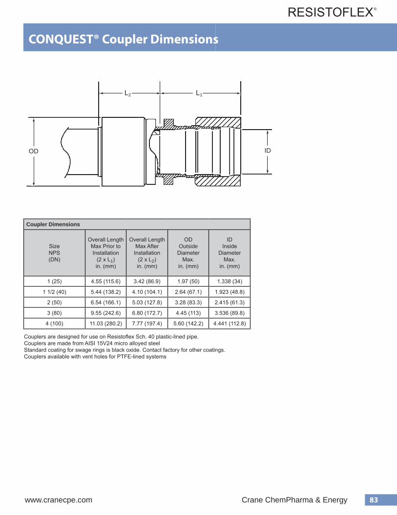
83www.cranecpe.com Crane ChemPharma & Energy
Coupler Dimensions
SizeNPS(DN)
Overall Length Max Prior toInstallation
(2 x L1)in. (mm)
Overall Length Max After
Installation(2 x L2)in. (mm)
ODOutside
DiameterMax.
in. (mm)
IDInside
DiameterMax.
in. (mm)
1 (25) 4.55 (115.6) 3.42 (86.9) 1.97 (50) 1.338 (34)
1 1/2 (40) 5.44 (138.2) 4.10 (104.1) 2.64 (67.1) 1.923 (48.8)
2 (50) 6.54 (166.1) 5.03 (127.8) 3.28 (83.3) 2.415 (61.3)
3 (80) 9.55 (242.6) 6.80 (172.7) 4.45 (113) 3.536 (89.8)
4 (100) 11.03 (280.2) 7.77 (197.4) 5.60 (142.2) 4.441 (112.8)
76
CONQUEST Coupler Dimensions
e z i S g n i t t i F ) m m ( . n i
L x 2 ( 1 ) h t g n e L l l a r e v O
o t r o i r P . x a M n o i t a l l a t s n I
L x 2 ( 2 ) , h t g n e L l l a r e v O
n o i t a l l a t s n I
D e d i s t u O
, r e t e m a i D . x a M
I e d i s n I
, r e t e m a i D . x a M
1 ) 5 2 ( 5 5 . 4 2 4 . 3 7 9 . 1 8 3 3 . 1
2 / 1 1 ) 0 4 ( 4 4 . 5 0 1 . 4 4 6 . 2 3 2 9 . 1
2 ) 0 5 ( 4 5 . 6 3 0 . 5 8 2 . 3 5 1 4 . 2
3 ) 0 8 ( 5 5 . 9 0 8 . 6 5 4 . 4 6 3 5 . 3
4 ) 0 0 1 ( 3 0 . 1 1 7 7 . 7 0 6 . 5 1 5 5 . 4
1. Fittings are designed for use on Resistoflex plastic-lined steel pipe, schedule 40. 2. Standard coating for Swage Rings is black oxide per LMS-93-12. Contact factory for other platings. 3. Fittings available with and without 1/8” vent hole between tool flange.
®
. x a M After
G
OD ID
L2 L1
Couplers are designed for use on Resistoflex Sch. 40 plastic-lined pipe.Couplers are made from AISI 15V24 micro alloyed steelStandard coating for swage rings is black oxide. Contact factory for other coatings.Couplers available with vent holes for PTFE-lined systems
CONQUEST® Coupler Dimensions

84 Crane ChemPharma & Energy www.cranecpe.com
Tapped Vent CONQUEST® CouplerTapped Vent CONQUEST ® Couplers
• Vent Extenders
For insulated pipe, vent paths should be provided between vent holes and the atmosphere. Failure to do so often results in accelerated corrosion of the steel shell and contamination of the insulation. (Learn more about Venting and Insulation). PTFE-lined CONQUEST is designed to vent at the coupling. The coupling has a 1/8" NPT tapped vent hole which allows extenders to be threaded in, and routed through the insulation.
• Leak Detection
• Collection Systems
In some cases, venting of even minute quantities of permeants to the atmosphere is undesirable. This may be true with extremely hazardous or toxic chemicals, or in environmentally sensitive areas. The tapped vent allows attachment of collection systems to prevent permeant release to atmosphere.
High Integrity vent extender featuring Fire-Safe Design
A Hastelloy ® porous disc vent fitting is shipped with the coupler as an optional addition to the completed installation. It’s porous nature allows permeated gases to escape the system, but contains any entrained liquids which may result from a liner breech. The vent fitting is also designed according to the same principles as the Fire-Safe Factory Mutual approved HIF system.
Dimension Differences
The tapped vent coupler is different than the standard vented coupler. The tapped vent holes required a thicker cross section in the coupler body than is possible with the stan- dard coupler. The groove that accommodates the jaw of the installation tool was previously located in the center of the coupler. The new center rib requires that the groove be located on both sides of the new rib. These changes add to the overall length of the coupler. There is adequate design tolerance in the CONQUEST ® fittings to use the longer tapped vent coupler without concern for joint make-up clearance. The exact length of standard vented and the tapped vent couplers are as follows:
CONQUEST Plastic Lined Piping uses a mechanical coupler over a welded liner to provide a leak-free, flangeless joint. PTFE lined systems require a venting system to prevent permeants from collecting between the liner and steel shell. The tapped vent coupler provides more flexibility by allowing a variety of devices to be attached to the coupler:
A breech in the liner or weld can result in fluid traveling between the liner OD and metal ID to the annular space between the butt weld and the coupling body. Attachment of sensors to the tapped vent may provide early warning of a liner failure.
To accomodate the extra thickness, a center rib has been added to the coupler body
Standard CouplerTapped Coupler
Coupler Dimensions
SizeNPS(DN)
Standard Couplerw/ or w/o vent holes Tapped Vent Coupler
As-Shipped Length
in. (mm)
InstalledLength
in. (mm)
As-Shipped Length
in. (mm)
InstalledLength
in. (mm)
1 (25) 4.55 (115.6) 3.37 (85.6) 5.64 (143.3) 4.51 (114.6)
1 1/2 (40) 5.44 (138.2) 4.06 (103.1) 6.55 (166.4) 5.21 (132.3)
2 (50) 6.54 (166.1) 5 (127) 7.68 (195.1) 6.15 (156.2)
3 (80) 9.55 (242.6) 6.81 (173) 10.76 (273.3) 8.16 (207.3)
4 (100) 11.03 (280.2) 7.75 (196.9) 12.02 (305.3) 9 (228.6)
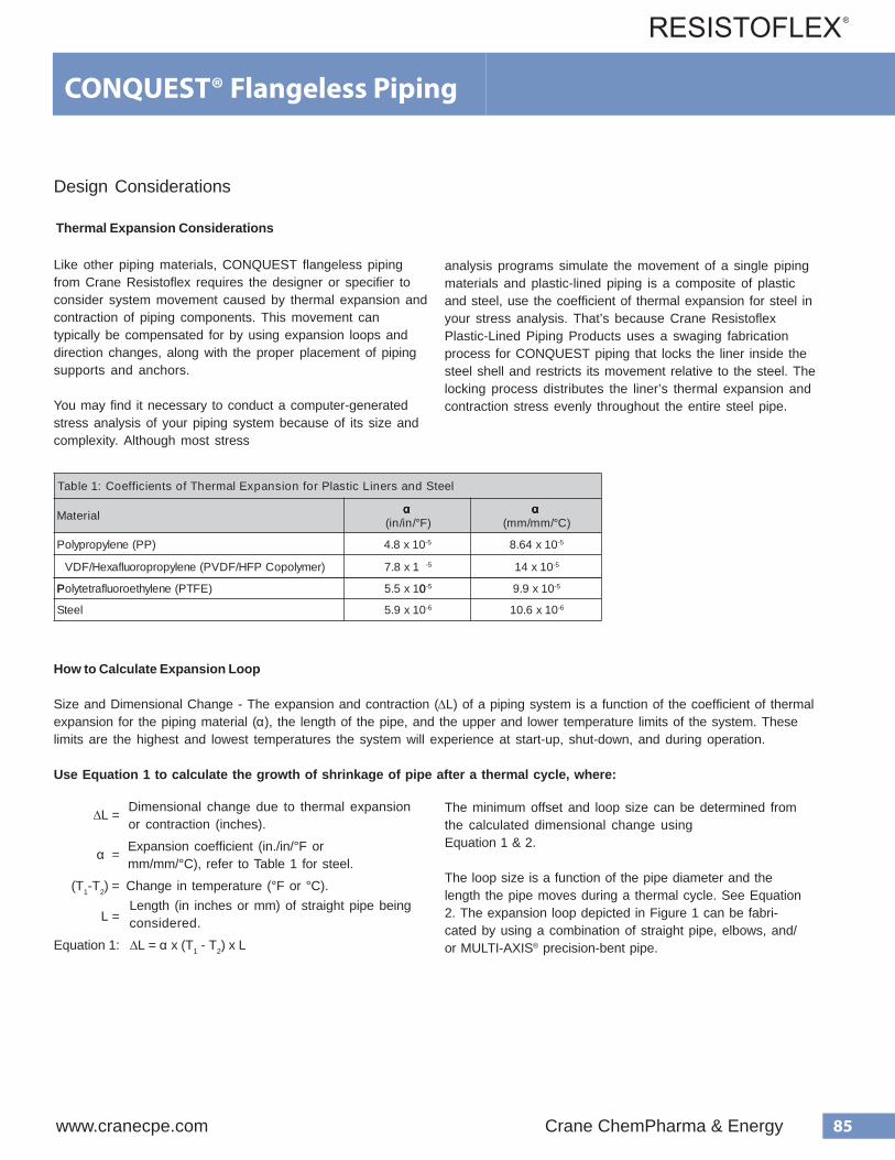
85www.cranecpe.com Crane ChemPharma & Energy
CONQUEST® Flangeless Piping
Design Considerations
Thermal Expansion Considerations
Like other piping materials, CONQUEST flangeless piping from Crane Resistoflex requires the designer or specifier to consider system movement caused by thermal expansion and contraction of piping components. This movement can typically be compensated for by using expansion loops and direction changes, along with the proper placement of piping supports and anchors.
You may find it necessary to conduct a computer-generated stress analysis of your piping system because of its size and complexity. Although most stress
analysis programs simulate the movement of a single piping materials and plastic-lined piping is a composite of plastic and steel, use the coefficient of thermal expansion for steel in your stress analysis. That’s because Crane Resistoflex Plastic-Lined Piping Products uses a swaging fabrication process for CONQUEST piping that locks the liner inside the steel shell and restricts its movement relative to the steel. The locking process distributes the liner’s thermal expansion and contraction stress evenly throughout the entire steel pipe.
How to Calculate Expansion Loop
Size and Dimensional Change - The expansion and contraction (∆L) of a piping system is a function of the coefficient of thermalexpansion for the piping material (α), the length of the pipe, and the upper and lower temperature limits of the system. Theselimits are the highest and lowest temperatures the system will experience at start-up, shut-down, and during operation.
Use Equation 1 to calculate the growth of shrinkage of pipe after a thermal cycle, where:
∆L =
α =
(T1-T2) =
L =
Dimensional change due to thermal expansionor contraction (inches).
Expansion coefficient (in./in/°F ormm/mm/°C), refer to Table 1 for steel.
Change in temperature (°F or °C).Length (in inches or mm) of straight pipe beingconsidered.
Equation 1: ∆L = α x (T1 - T2) x L
The minimum offset and loop size can be determined fromthe calculated dimensional change usingEquation 1 & 2.
The loop size is a function of the pipe diameter and thelength the pipe moves during a thermal cycle. See Equation2. The expansion loop depicted in Figure 1 can be fabri-cated by using a combination of straight pipe, elbows, and/or MULTI-AXIS® precision-bent pipe.
l e e t S d n a s r e n i L c i t s a l P r o f n o i s n a p x E l a m r e h T f o s t n e i c i f f e o C : 1 e l b a T
l a i r e t a M α α α α α ) F ° / n i / n i (
α α α α α ) C ° / m m / m m (
) P P ( e n e l y p o r p y l o P 0 1 x 8 . 4 5 - 0 1 x 4 6 . 8 5 -
)remylopoCPFH/FDVP(enelyporporoulfaxeH/FDV
P 0
1x8.7 5- 01x41 5-
)EFTP(enelyhteoroulfartetyloP 01x5.5 5- 01x9.9 5-
leetS 01x9.5 6- 01x6.01 6-
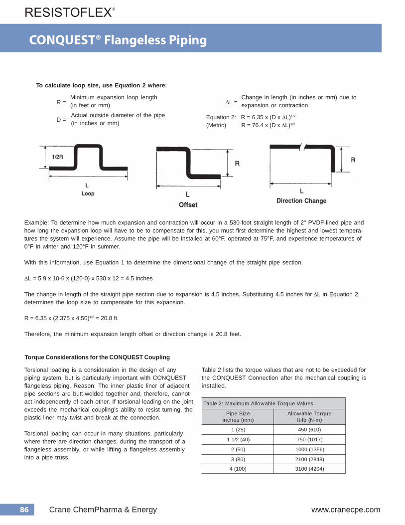
86 Crane ChemPharma & Energy www.cranecpe.com
CONQUEST® Flangeless Piping
To calculate loop size, use Equation 2 where:
R =
D =
Minimum expansion loop length (in feet or mm)
Actual outside diameter of the pipe (in inches or mm)
∆ L = Change in length (in inches or mm) due to expansion or contraction
Equation 2: R = 6.35 x (D x ∆ L) 1/2
(Metric) R = 76.4 x (D x ∆ L) 1/2
Torsional loading is a consideration in the design of anypiping system, but is particularly important with CONQUESTflangeless piping. Reason: The inner plastic liner of adjacentpipe sections are butt-welded together and, therefore, cannotact independently of each other. If torsional loading on the jointexceeds the mechanical coupling’s ability to resist turning, theplastic liner may twist and break at the connection.
Torsional loading can occur in many situations, particularlywhere there are direction changes, during the transport of aflangeless assembly, or while lifting a flangeless assemblyinto a pipe truss.
Table 2 lists the torque values that are not to be exceeded forthe CONQUEST Connection after the mechanical coupling isinstalled.
Example: To determine how much expansion and contraction will occur in a 530-foot straight length of 2" PVDF-lined pipe and how long the expansion loop will have to be to compensate for this, you must first determine the highest and lowest tempera- tures the system will experience. Assume the pipe will be installed at 60°F, operated at 75°F, and experience temperatures of 0°F in winter and 120°F in summer.
With this information, use Equation 1 to determine the dimensional change of the straight pipe section.
∆ L = 5.9 x 10-6 x (120-0) x 530 x 12 = 4.5 inches
The change in length of the straight pipe section due to expansion is 4.5 inches. Substituting 4.5 inches for ∆ L in Equation 2, determines the loop size to compensate for this expansion.
R = 6.35 x (2.375 x 4.50) 1/2 = 20.8 ft.
Therefore, the minimum expansion length offset or direction change is 20.8 feet.
Torque Considerations for the CONQUEST Coupling
seulaVeuqroTelbawollAmumixaM:2elbaT
eziSepiP)mm(sehcni
euqroTelbawollA)m-N(bl-tf
)52(1 )016(054
)04(2/11 )7101(057
)05(2 )6531(0001
)08(3 )8482(0012
)001(4 )4024(0013

87www.cranecpe.com Crane ChemPharma & Energy
CONQUEST® Flangeless Piping for PTFETesting and Verification Data for CONQUEST Flangeless Piping Systems 1" to 4"Polytetrafluoroethylene (PTFE) Lined Systems
To verify the integrity of the CONQUEST flangeless connection, Resistoflex conducted tests on three separate components ofthe connection:
• The mechanical coupling, which has been developed by LOKRING for use with RESISTOFLEX Plastic-Lined Piping.• The liner butt weld.• The CONQUEST flangeless connection as a whole.
A summary of these tests and results are contained in this technical data sheet.
Testing of the RESISTOFLEX / LOKRING™ Mechanical Coupling
A. Coupling Bend Test
Test Procedure- Mechanical couplings were used to join twosections of plastic-lined pipe from RESISTOFLEX Plastic-Lined Piping Products. These newly created sections of joinedpipe were then subjected to a full reverse bend test.
These tests were performed by the Lokring Corporation attheir facility in Foster City, California. The load applied to thebend was the equivalent to subjecting the pipe to a minimumstress of 30 psi (2.07 bar). The minimum number of cyclesrequired to pass the test was set at 7,000 cycles. The test wascarried out until either 7,000 cycles were completed orcoupling failure was observed.
Results - All four pipe sizes tested passes the minimumrequirement of 7,000 cycles. The test on the 1" (25 mm) sizewas allowed to continue in order to determine approximatelyhow many full reversing cycles the pipe could actually with-stand. The test terminated after 71,089 cycles and still nofailure was observed.
B. Coupling Burst Test
Test Procedure - Test samples were produced by connectingtwo sections of plastic-lined pipe from RESISTOFLEX Plastic-Lined Piping Products with a mechanical coupling. Each endwas then capped. The cap at one end was equipped with aconnection that permitted internal hydraulic pressure to beapplied. The requirement to pass the test was set at havingthe pipe fail before the coupling. Internal pressure was thenapplied and steadily increased. These tests were performedby the Lokring Corporation at their facility in Foster City,California.
Results - The internal pressure was increased until thecoupling failed or the pipe burst. Testing was completed forthree different sizes of plastic-lined pipe and is summarized inTable 2. Note that in each case the pipe burst, which demon-strates that the coupling is actually stronger than the steelpipe.
stluseRtseTdneB-1elbaTeziSepiP)mm(.ni
forebmuNselcyC tluseR
1 (25) 71,089 PASSPASS
PASSPASS
7,399
7,2517,500
1 1/2 (40)
2 (50)3 (80)
stluseRtseTtsruBgnilpuoC-2elbaTeziSepiP)mm(.ni
erusserPtsruB)raB(isp tluseR
2 (50) 7,500 (517) Pipe Rupture
3 (80) 10,000 (690) Pipe Rupture4 (100) 5,200 (359) Pipe Rupture
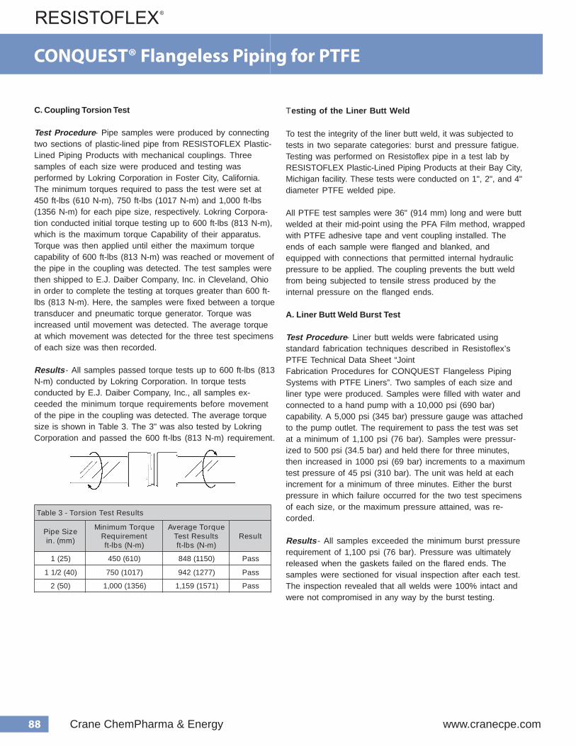
88 Crane ChemPharma & Energy www.cranecpe.com
C. Coupling Torsion Test
Test Procedure - Pipe samples were produced by connecting two sections of plastic-lined pipe from RESISTOFLEX Plastic- Lined Piping Products with mechanical couplings. Three samples of each size were produced and testing was performed by Lokring Corporation in Foster City, California. The minimum torques required to pass the test were set at 450 ft-lbs (610 N-m), 750 ft-lbs (1017 N-m) and 1,000 ft-lbs (1356 N-m) for each pipe size, respectively. Lokring Corpora- tion conducted initial torque testing up to 600 ft-lbs (813 N-m), which is the maximum torque Capability of their apparatus. Torque was then applied until either the maximum torque capability of 600 ft-lbs (813 N-m) was reached or movement of the pipe in the coupling was detected. The test samples were then shipped to E.J. Daiber Company, Inc. in Cleveland, Ohio in order to complete the testing at torques greater than 600 ft- lbs (813 N-m). Here, the samples were fixed between a torque transducer and pneumatic torque generator. Torque was increased until movement was detected. The average torque at which movement was detected for the three test specimens of each size was then recorded.
Results - All samples passed torque tests up to 600 ft-lbs (813 N-m) conducted by Lokring Corporation. In torque tests conducted by E.J. Daiber Company, Inc., all samples ex- ceeded the minimum torque requirements before movement of the pipe in the coupling was detected. The average torque size is shown in Table 3. The 3" was also tested by Lokring Corporation and passed the 600 ft-lbs (813 N-m) requirement.
Testing of the Liner Butt Weld
To test the integrity of the liner butt weld, it was subjected to tests in two separate categories: burst and pressure fatigue. Testing was performed on Resistoflex pipe in a test lab by RESISTOFLEX Plastic-Lined Piping Products at their Bay City, Michigan facility. These tests were conducted on 1", 2", and 4" diameter PTFE welded pipe.
All PTFE test samples were 36" (914 mm) long and were butt welded at their mid-point using the PFA Film method, wrapped with PTFE adhesive tape and vent coupling installed. The ends of each sample were flanged and blanked, and equipped with connections that permitted internal hydraulic pressure to be applied. The coupling prevents the butt weld from being subjected to tensile stress produced by the internal pressure on the flanged ends.
A. Liner Butt Weld Burst Test
Test Procedure - Liner butt welds were fabricated using standard fabrication techniques described in Resistoflex’s PTFE Technical Data Sheet “Joint Fabrication Procedures for CONQUEST Flangeless Piping Systems with PTFE Liners”. Two samples of each size and liner type were produced. Samples were filled with water and connected to a hand pump with a 10,000 psi (690 bar) capability. A 5,000 psi (345 bar) pressure gauge was attached to the pump outlet. The requirement to pass the test was set at a minimum of 1,100 psi (76 bar). Samples were pressur- ized to 500 psi (34.5 bar) and held there for three minutes, then increased in 1000 psi (69 bar) increments to a maximum test pressure of 45 psi (310 bar). The unit was held at each increment for a minimum of three minutes. Either the burst pressure in which failure occurred for the two test specimens of each size, or the maximum pressure attained, was re- corded.
Results - All samples exceeded the minimum burst pressure requirement of 1,100 psi (76 bar). Pressure was ultimately released when the gaskets failed on the flared ends. The samples were sectioned for visual inspection after each test. The inspection revealed that all welds were 100% intact and were not compromised in any way by the burst testing.
s t l u s e R t s e T n o i s r o T - 3 e l b a T
e z i S e p i P ) m m ( . n i
e u q r o T m u m i n i M t n e m e r i u q e R
) m - N ( s b l - t f
e u q r o T e g a r e v A s t l u s e R t s e T ) m - N ( s b l - t f
t l u s e R
) 5 2 ( 1 ) 0 1 6 ( 0 5 4 ) 0 5 1 1 ( 8 4 8 s s a P
) 0 4 ( 2 / 1 1 ) 7 1 0 1 ( 0 5 7 ) 7 7 2 1 ( 2 4 9 s s a P
) 0 5 ( 2 ) 6 5 3 1 ( 0 0 0 , 1 ) 1 7 5 1 ( 9 5 1 , 1 s s a P
CONQUEST® Flangeless Piping for PTFE

89www.cranecpe.com Crane ChemPharma & Energy
† Gaskets on flared ends failed without compromising the weld integrity.
B. Liner Butt Weld Pressure Fatigue Test
Test Procedure - Test samples were 36" (914 mm) long and were butt-welded together at their mid-point. The samples were connected to a high-pressure piston pump capable of producing 1,400 psi (97 bar). Description of pressure fatigue test cycle: increase internal pressure to 550 psi (38 bar), hold for 10 seconds, reduce pressure to 50 psi (3.4 bar), hold for 5 seconds, then increase to 550 psi (38 bar) to repeat the cycle. The minimum requirement to pass the test was set at 7,000 cycles.
Results - All samples withstood the minimum 7,000 cycleswithout displaying any evidence of failure. All tests were allowed to continue in order to determine approximately how many pressure fatigue cycles the butt weld could actually withstand. The test was terminated after 100,000 cycles and still no failure was observed. The samples were sectioned for a visual inspection after each test. The inspection revealed that all welds were 100% intact and were not compromised in any way by the fatigue testing.
Testing of CONQUEST connection
To test the integrity of the CONQUEST connection, it was subjected to tests in two separate categories: ASTM Steam/ Cold Water and Cold Temperature.
A. ASTM Steam/Cold Water
Test Procedure - Testing was performed on RESISTOFLEX Plastic-Lined Pipe in a test lab by RESISTOFLEX Plastic-Lined Piping Products at their Bay City, Michigan facility. Tests were conducted on two sets of 1", 1-1/2", 2", 3", and 4" welded diameter PTFE-lined pipe spools. Plastic-lined pipe spools were subjected to the appropriate ASTM Steam/Cold Water test for lined pipe. Each spool was 20 feet (12.2 m) long, consisting of two 10-foot (6.1 m) lengths joined by CON- QUEST flangeless connection at the mid-point. The test spools contained the standard flanged connection at each end. The test involved subjecting the spool to 100 alternating cycles of heating with steam, then cooling with water.
Results - All spools passed the requirements of the ASTM Steam/Cold Water test. These samples were sectioned for a visual inspection after each test. The inspection revealed that all welds were 100% intact and were not compromised in any way by the Steam/Cold Water testing.
B. Cold Temperature Test
Test Procedure - Testing was performed on RESISTOFLEX Plastic-Lined Pipe in a test lab by RESISTOFLEX Plastic-Lined Piping Products at their Bay City, Michigan facility. Spools were fabricated by joining two 10-foot (3 m) sections with a CON- QUEST flangeless connection at the mid-point. Testing included 1", 1-1/2", 2", 3", and 4" diameter welded PTFE-lined pipe spools. The test involved inserting a sample into a freezer with a -40°F (-40°C) capability and cooling it until either the liner failed or the maximum low temperature was reached. Description of test procedure: Insert sample into freezer with temperature set at 20°F (-7°C) and hold for a minimum of 8 hours. Visually inspect each sample and, if no liner failure has occurred, reduce the temperature in 10°F (6°C) increments and hold at each increment for a minimum of 8 hours. Visually inspect each sample after each 8-hour interval.
Results - All spools withstood a low freezer temperature of - 20°F (-29°C). The samples were sectioned for a visual inspection after each test. The inspection revealed that all welds were 100% intact and were not compromised in any way by the freeze testing.
s t l u s e R t s e T t s r u B - 4 e l b a T
e z i S e p i P ) m m ( . n i
r e n i L e p y T
t s r u B m u m i n i M t n e m e r i u q e R e r u s s e r P
) r a B ( i s p
t s r u B . x a M e r u s s e r P t s e T
) r a B ( i s p
) 5 2 ( 1 E F T P ) 6 7 ( 0 0 1 , 1 ) 0 1 3 ( 0 0 5 , 4 †
) 0 5 ( 2 E F T P ) 6 7 ( 0 0 1 , 1 ) 0 1 3 ( 0 0 5 , 4 †
) 0 0 1 ( 4 E F T P ) 6 7 ( 0 0 1 , 1 ) 0 1 3 ( 0 0 5 , 4 †
s t l u s e R t s e T e u g i t a F e r u s s e r P - 5 e l b a T
e z i S e p i P ) m m ( . n i
r e n i L e p y T
r e b m u N m u m i n i M d e r i u q e R s e l c y C f o
f o r e b m u N l a u t c A d e v e i h c A s e l c y C
) 5 2 ( 1 E F T P 0 0 0 , 7 0 0 0 , 0 0 1
) 0 5 ( 2 E F T P 0 0 0 , 7 0 0 0 , 0 0 1
) 0 0 1 ( 4 E F T P 0 0 0 , 7 0 0 0 , 0 0 1
CONQUEST® Flangeless Piping for PTFE
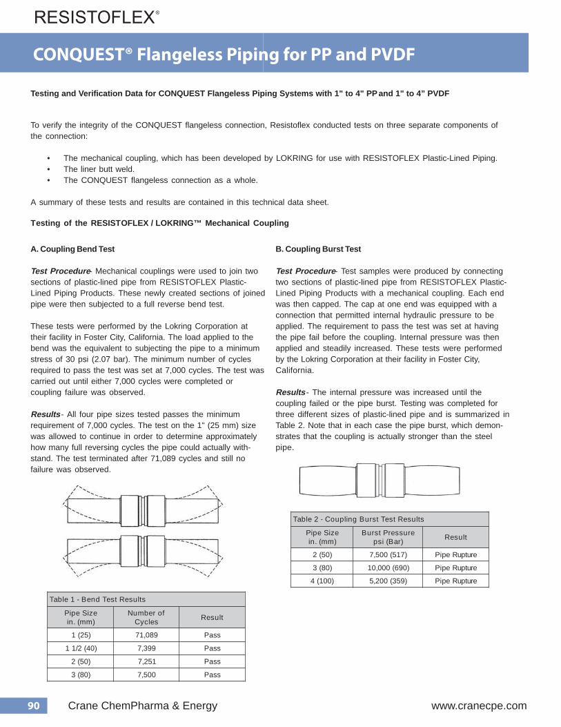
90 Crane ChemPharma & Energy www.cranecpe.com
CONQUEST® Flangeless Piping for PP and PVDF
Testing and Verification Data for CONQUEST Flangeless Piping Systems with 1" to 4" PP and 1" to 4” PVDF
A. Coupling Bend Test
Test Procedure - Mechanical couplings were used to join two sections of plastic-lined pipe from RESISTOFLEX Plastic- Lined Piping Products. These newly created sections of joined pipe were then subjected to a full reverse bend test.
These tests were performed by the Lokring Corporation at their facility in Foster City, California. The load applied to the bend was the equivalent to subjecting the pipe to a minimum stress of 30 psi (2.07 bar). The minimum number of cycles required to pass the test was set at 7,000 cycles. The test was carried out until either 7,000 cycles were completed or coupling failure was observed.
Results - All four pipe sizes tested passes the minimum requirement of 7,000 cycles. The test on the 1" (25 mm) size was allowed to continue in order to determine approximately how many full reversing cycles the pipe could actually with- stand. The test terminated after 71,089 cycles and still no failure was observed.
B. Coupling Burst Test
Test Procedure - Test samples were produced by connecting two sections of plastic-lined pipe from RESISTOFLEX Plastic- Lined Piping Products with a mechanical coupling. Each end was then capped. The cap at one end was equipped with a connection that permitted internal hydraulic pressure to be applied. The requirement to pass the test was set at having the pipe fail before the coupling. Internal pressure was then applied and steadily increased. These tests were performed by the Lokring Corporation at their facility in Foster City, California.
Results - The internal pressure was increased until the coupling failed or the pipe burst. Testing was completed for three different sizes of plastic-lined pipe and is summarized in Table 2. Note that in each case the pipe burst, which demon- strates that the coupling is actually stronger than the steel pipe.
To verify the integrity of the CONQUEST flangeless connection, Resistoflex conducted tests on three separate components of the connection:
• The mechanical coupling, which has been developed by LOKRING for use with RESISTOFLEX Plastic-Lined Piping. • The liner butt weld. • The CONQUEST flangeless connection as a whole.
A summary of these tests and results are contained in this technical data sheet.
Testing of the RESISTOFLEX / LOKRING™ Mechanical Coupling
s t l u s e R t s e T d n e B - 1 e l b a T
e z i S e p i P ) m m ( . n i
f o r e b m u N s e l c y C t l u s e R
) 5 2 ( 1 9 8 0 , 1 7 s s a P
) 0 4 ( 2 / 1 1 9 9 3 , 7 s s a P
) 0 5 ( 2 1 5 2 , 7 s s a P
) 0 8 ( 3 0 0 5 , 7 s s a P
s t l u s e R t s e T t s r u B g n i l p u o C - 2 e l b a T
e z i S e p i P ) m m ( . n i
e r u s s e r P t s r u B ) r a B ( i s p t l u s e R
) 0 5 ( 2 ) 7 1 5 ( 0 0 5 , 7 e r u t p u R e p i P
) 0 8 ( 3 ) 0 9 6 ( 0 0 0 , 0 1 e r u t p u R e p i P
) 0 0 1 ( 4 ) 9 5 3 ( 0 0 2 , 5 e r u t p u R e p i P

91www.cranecpe.com Crane ChemPharma & Energy
CONQUEST® Flangeless Piping for PP and PVDF
C. Coupling Torsion Test
Test Procedure - Pipe samples were produced by connect- ing two sections of plastic-lined pipe from RESISTOFLEX Plastic-Lined Piping Products with mechanical couplings. Three samples of each size were produced and testing was performed by Lokring Corporation in Foster City, California. The minimum torques required to pass the test were set at 450 ft-lbs (610 N-m), 750 ft-lbs (1017 N-m) and 1,000 ft-lbs (1356 N-m) for each pipe size, respectively. Lokring Corporation conducted initial torque testing up to 600 ft-lbs (813 N-m), which is the maximum torque Capability of their apparatus. Torque was then applied until either the maximum torque capability of 600 ft-lbs (813 N- m) was reached or movement of the pipe in the coupling was detected. The test samples were then shipped to E.J. Daiber Company, Inc. in Cleveland, Ohio in order to complete the testing at torques greater than 600 ft-lbs (813 N-m). Here, the samples were fixed between a torque transducer and pneumatic torque generator. Torque was increased until movement was detected. The average torque at which movement was detected for the three test specimens of each size was then recorded.
Results - All samples passed torque tests up to 600 ft-lbs (813 N-m) conducted by Lokring Corporation. In torque tests conducted by E.J. Daiber Company, Inc., all samples exceeded the minimum torque requirements before movement of the pipe in the coupling was detected. The average torque size is shown in Table 3. The 3" was also tested by Lokring Corporation and passed the 600 ft-lbs (813 N-m) requirement.
T esting of the Liner Butt W eld
To test the integrity of the liner butt weld, it was subjected to tests in two separate categories: burst and pressure fatigue. Testing was performed on Resistoflex pipe in a test lab by RESISTOFLEX Plastic-Lined Piping Products at their Bay City, Michigan facility. These tests were con- ducted three sets of plastic-lined pipe. The first set was lined in polypropylene (PP), the second in polyvinylidene (PVDF), and lastly in perfluoroalkoxy (PFA).
All test samples were 24" (610 mm) long and were butt welded at their mid-point. The ends of each sample were flanged and blanked, and equipped with connections that permitted internal hydraulic pressure to be applied. Three steel bars were then welded to the steel shell spanning the exposed liner in the area that contained the butt weld. This prevented the butt weld from being subjected to tensile stress produced by the internal pressure on the flanged ends. The liners and butt-welds were visually monitored throughout the testing.
A. Liner Butt Weld Burst Test
Test Procedure - Liner butt welds were fabricated using standard fabrication techniques described in Resistoflex’s Technical Data Sheet “Joint Fabrication Procedures for CONQUEST Flangeless Piping Systems with PP, PVDF/HFP, and PFA-Liners”. Three samples of each size and liner type were produced. Samples were filled with water and connected to a hand pump witha 10,000 psi (690 bar) capability. A 5,000 psi (345 bar) pressure gauge was attached to the pump outlet. The requirement to pass the test was set at a minimum of 1,100 psi (76 bar). Samples were pressurized to 500 psi (34.5 bar) and held there for three minutes, then increased in 1,000 psi (69 bar) increments and held at each incre- ment for a minimum of three minutes. The burst pressure range in which failure occurred for the three test speci- mens of each size was recorded.
Results - All samples exceeded the minimum burst pressure requirement of 1,100 psi (76 bar). Failures ultimately occurred in the burst pressure range given in Table 4. However, it should be noted that all failures occurred in the exposed portion of the liner and not at the butt weld faces.
s t l u s e R t s e T n o i s r o T - 3 e l b a T
e z i S e p i P ) m m ( . n i
e u q r o T m u m i n i M t n e m e r i u q e R
) m - N ( s b l - t f
e u q r o T e g a r e v A s t l u s e R t s e T ) m - N ( s b l - t f
t l u s e R
) 5 2 ( 1 ) 0 1 6 ( 0 5 4 ) 0 5 1 1 ( 8 4 8 s s a P
) 0 4 ( 2 / 1 1 ) 7 1 0 1 ( 0 5 7 ) 7 7 2 1 ( 2 4 9 s s a P
) 0 5 ( 2 ) 6 5 3 1 ( 0 0 0 , 1 ) 1 7 5 1 ( 9 5 1 , 1 s s a P
For 3” the coupling withstood in excess of 2,000 ft-lbs of torque.
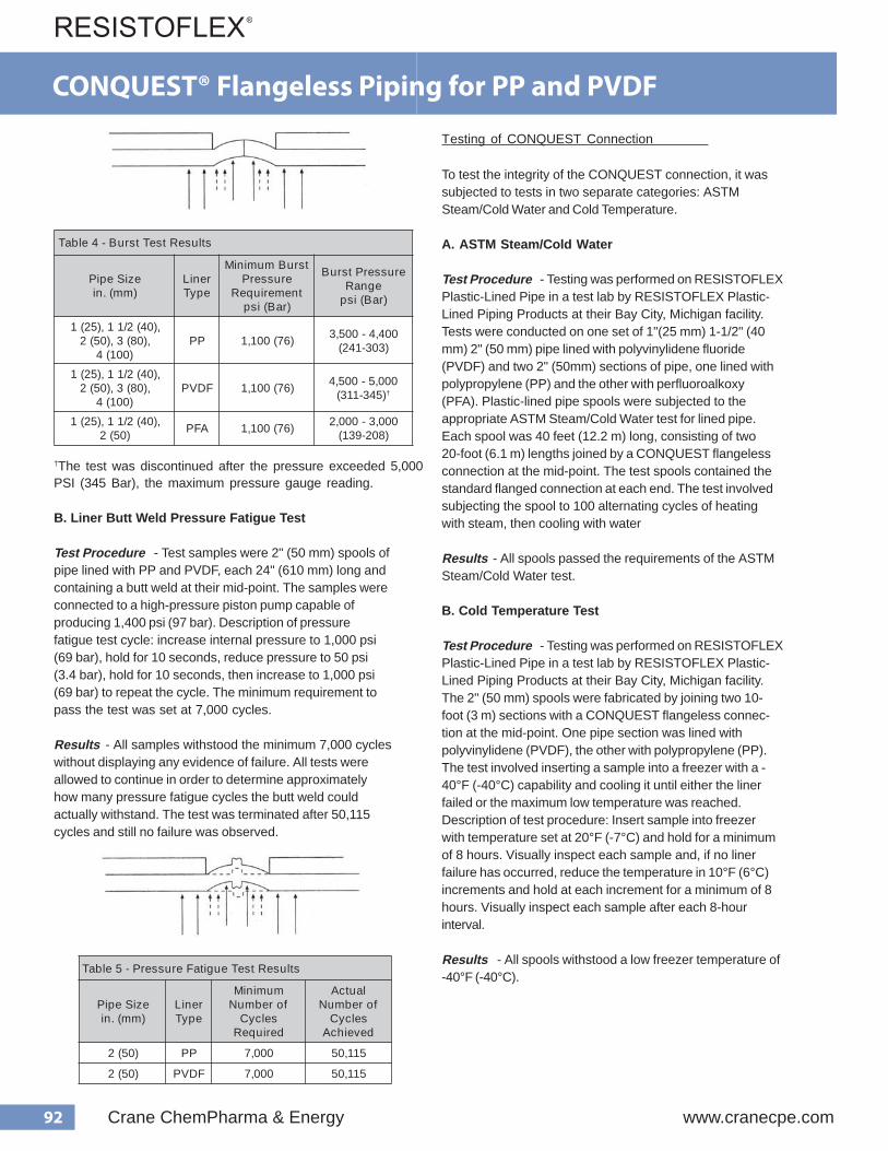
92 Crane ChemPharma & Energy www.cranecpe.com
CONQUEST® Flangeless Piping for PP and PVDF
† The test was discontinued after the pressure exceeded 5,000 PSI (345 Bar), the maximum pressure gauge reading.
B. Liner Butt Weld Pressure Fatigue Test
Test Procedure - Test samples were 2" (50 mm) spools ofpipe lined with PP and PVDF, each 24" (610 mm) long andcontaining a butt weld at their mid-point. The samples wereconnected to a high-pressure piston pump capable ofproducing 1,400 psi (97 bar). Description of pressurefatigue test cycle: increase internal pressure to 1,000 psi(69 bar), hold for 10 seconds, reduce pressure to 50 psi(3.4 bar), hold for 10 seconds, then increase to 1,000 psi(69 bar) to repeat the cycle. The minimum requirement topass the test was set at 7,000 cycles.
Results - All samples withstood the minimum 7,000 cycleswithout displaying any evidence of failure. All tests wereallowed to continue in order to determine approximatelyhow many pressure fatigue cycles the butt weld couldactually withstand. The test was terminated after 50,115cycles and still no failure was observed.
Testing of CONQUEST Connection
To test the integrity of the CONQUEST connection, it wassubjected to tests in two separate categories: ASTMSteam/Cold Water and Cold Temperature.
A. ASTM Steam/Cold Water
Test Procedure - Testing was performed on RESISTOFLEXPlastic-Lined Pipe in a test lab by RESISTOFLEX Plastic-Lined Piping Products at their Bay City, Michigan facility.Tests were conducted on one set of 1"(25 mm) 1-1/2" (40mm) 2" (50 mm) pipe lined with polyvinylidene fluoride(PVDF) and two 2" (50mm) sections of pipe, one lined withpolypropylene (PP) and the other with perfluoroalkoxy(PFA). Plastic-lined pipe spools were subjected to theappropriate ASTM Steam/Cold Water test for lined pipe.Each spool was 40 feet (12.2 m) long, consisting of two20-foot (6.1 m) lengths joined by a CONQUEST flangelessconnection at the mid-point. The test spools contained thestandard flanged connection at each end. The test involvedsubjecting the spool to 100 alternating cycles of heatingwith steam, then cooling with water
Results - All spools passed the requirements of the ASTMSteam/Cold Water test.
B. Cold Temperature Test
Test Procedure - Testing was performed on RESISTOFLEXPlastic-Lined Pipe in a test lab by RESISTOFLEX Plastic-Lined Piping Products at their Bay City, Michigan facility.The 2" (50 mm) spools were fabricated by joining two 10-foot (3 m) sections with a CONQUEST flangeless connec-tion at the mid-point. One pipe section was lined withpolyvinylidene (PVDF), the other with polypropylene (PP).The test involved inserting a sample into a freezer with a -40°F (-40°C) capability and cooling it until either the linerfailed or the maximum low temperature was reached.Description of test procedure: Insert sample into freezerwith temperature set at 20°F (-7°C) and hold for a minimumof 8 hours. Visually inspect each sample and, if no linerfailure has occurred, reduce the temperature in 10°F (6°C)increments and hold at each increment for a minimum of 8hours. Visually inspect each sample after each 8-hourinterval.
Results - All spools withstood a low freezer temperature of-40°F (-40°C).
s t l u s e R t s e T t s r u B - 4 e l b a T
e z i S e p i P ) m m ( . n i
r e n i L e p y T
t s r u B m u m i n i M e r u s s e r P
t n e m e r i u q e R ) r a B ( i s p
e r u s s e r P t s r u B e g n a R
) r a B ( i s p
, ) 0 4 ( 2 / 1 1 , ) 5 2 ( 1 , ) 0 8 ( 3 , ) 0 5 ( 2
) 0 0 1 ( 4 P P ) 6 7 ( 0 0 1 , 1 0 0 4 , 4 - 0 0 5 , 3
) 3 0 3 - 1 4 2 (
, ) 0 4 ( 2 / 1 1 , ) 5 2 ( 1 , ) 0 8 ( 3 , ) 0 5 ( 2
) 0 0 1 ( 4 F D V P ) 6 7 ( 0 0 1 , 1 0 0 0 , 5 - 0 0 5 , 4
) 5 4 3 - 1 1 3 ( †
, ) 0 4 ( 2 / 1 1 , ) 5 2 ( 1 ) 0 5 ( 2 A F P ) 6 7 ( 0 0 1 , 1 0 0 0 , 3 - 0 0 0 , 2
) 8 0 2 - 9 3 1 (
s t l u s e R t s e T e u g i t a F e r u s s e r P - 5 e l b a T
e z i S e p i P ) m m ( . n i
r e n i L e p y T
m u m i n i M f o r e b m u N
s e l c y C d e r i u q e R
l a u t c A f o r e b m u N
s e l c y C d e v e i h c A
) 0 5 ( 2 P P 0 0 0 , 7 5 1 1 , 0 5
) 0 5 ( 2 F D V P 0 0 0 , 7 5 1 1 , 0 5
93www.cranecpe.com Crane ChemPharma & Energy
Many specifiers of piping systems limit their economicanalysis to piping material costs only, because they arerelatively simple to estimate. Yet this approach creates somepitfalls when selecting either an installation of conventionalflanged plastic-lined piping (PLP) or an installation that fullyincorporates Resistoflex’s Joint Reduction Technologies(JRT), consisting of CONQUEST ® flangeless connections andMULTI-AXIS® precision bent piping. An evaluation that consid-ers only the cost of pipe, fittings, flanges and connectors mayresult in specification of a system with the higher life cyclecost.
Life Cycle Cost Considers All Cost Factors
Life cycle cost (LCC) analysis includes all costs of systemownership and permits selection of the less expensivesystem. Costs can be divided into the following categories:
• Initial acquisition costs• Initial acquisition labor• Operating and maintenance costs• Costs associated with flange leaks
When deciding to utilize JRT, it’s often helpful to perform theevaluation based on the LCC of current practice (i.e., the useof flanged PLP) and then consider which costs would changeif the system were designed and installed using the variousJoint Reduction Technologies. Different alternatives can beevaluated with the judicious use of JRT and elimination ofmany, but not all, flanged connections resulting in the mosteconomical PLP installation.
Cost Elements to Consider When Evaluating JRT vs.Conventional PLP
• Initial Acquisition Costs
- Pipe, fittings, flanges, venting & locking collars andCONQUEST® connectors. These are the items that arepurchased from the supplier of PLP. Pipe can be suppliedalready flanged, or spooled, ready for installation. If the pipewill be fabricated on-site, then a sufficient number of flangesand/or CONQUEST ® connectors should be purchased. Don’toverlook venting collars for PTFE (polytetrafluoroethylene) orPFA (perfluoroalkoxy) lined pipe if flanged pipe ends will befabricated onsite. These collars are not needed if the pipe isjoined with a CONQUEST ® flangeless connection.
- Nuts, bolts or studs needed to join flanged connections.
- Flange protectors or spray shields. Many corporate orgovernment regulations require that flanged connections becovered or protected so that if a leak occurs, it is eithercontained or flows in a controlled, predictable pattern insteadof spraying at the flanged connection.
- Registration of flanged connections in a corporate data-base. Often the location of a flanged connection must benoted in records so that its location, maintenance andinspection can be reported. One common technique is toattach a bar code label to the flanged connection, inputlocation and chemical service information into a database.Registration is essential if the service is covered by the 1990Clean Air Act Amendments (CAAA) or other similar lawsgoverning chemical processes. Many companies register allflanged connections in critical or hazardous services, even ifthe service isn’t currently included in regulations. This is oftendone either for safety reasons or in anticipation of changes inregulations. Registration usually occurs at the time of installa-tion and is in additional to the recurrent costs of periodicinspection.
- Items that are less costly when flanged connections areeliminated because the piping system is lighter in weightand has a more streamlined profile. These could include:
• number and type of hangers• support structure• diameter or configuration of insulation• complexity of heat tracing around connections
- Diameter of the piping system and size of pumps. Don’toverlook the improved flow characteristics of JRT, especially ofMULTI-AXIS® precision bent piping. The 3-D bends of MULTI-AXIS® create less pressure drop than the standard 1.5-Dbends of conventional PLP. It may be possible to specify asmaller diameter piping system and/or smaller pumps if JRTis specified instead of conventional PLP.
Initial Acquisition Labor
- Design and design review. Usually PLP systems aredesigned with all piping spool lengths calculated and shownon detailed isometric drawings. This level of detail is often notneeded if CONQUEST ® flangeless connections are used inpiping runs since the pipe can be field routed.
- Material acquisition cost. The cost of specifying, orderingand receiving materials can be reduced if the piping is boughtas bulk quantities of unflanged, standard length pipe insteadof numerous flanged spools with different custom lengths.Also the material acquisition costs for some items (like nuts,bolts, studs, flange protectors and spray shields) are reducedin direct portion to the number of flanged connections elimi-nated by the use of JRT.
Joint Reduction Technologies - Life Cycle Cost Estimating
94 Crane ChemPharma & Energy www.cranecpe.com
Joint Reduction Technologies - Life Cycle Cost Estimating
- Field fabrication of custom length pipe. The process of PLPcustom spool fabrication includes cutting and threading thepipe, installing and aligning the flange, installing the venting orlocking collar, heating the plastic stub, flaring the plastic face,cooling and removing the flaring die and installing a protectivewooden cover over the flared face. This process can be time-consuming and quality difficult to control if performed on-siteby personnel who fabricate PLP on an infrequent basis. Oftencustom spools are fabricated at the factory or by nearbystocking distributors who have fully equipped shops andcertified personnel that fabricate PLP routinely. If conventionalPLP is fabricated at the factory or by a distributor, then the costwill be part of the purchase price quoted by the supplier of thefabricated pipe. Understandably, flanged and fabricatedspools are more expensive than plain-end PLP.
- Cost of installation. This includes the cost of installing thepiping system and the associated nuts, bolts, studs, flangeprotectors and spray shields with conventional PLP or the costof fabricating a CONQUEST ® connection when the method isused to create a joint.
- Miscellaneous labor cost savings. Be sure to include laborcost savings if the use of lighter weigth, streamlined JRTpiping permits a reduction in the number of hangers andsupports and if the elimination of flanged connections speedsup the installation of insulation and heat tracing. Also, the timerequired for painting can be reduced when flanged connec-tions are eliminated. If installation time is reduced, then it’soften possible to reduce the time required for rental orrecharge of equipment like man-lifts.
- Start-up costs. This includes the time to hydrotest the pipingsystem and perform the recommended retorqing of bolts after24 hours of operation. When flanged connections are elimi-nated, the start-up time can be substantially reduced. Thismeans that the system is operational sooner and the processis out of commission for a shorter period of time.
Operating and maintenance costs
- Monitoring and associated paperwork. Government orcorporate regulations may require the periodic monitoring offlanged connection for leaks and records of that monitoringactivity. If a service is listed in the 1990 CAAA, then the connec-tion must be “sniffed” for fugitive emissions and detailedrecords maintained for submittal to the government. Themonitoring frequency ranges from every six months tobiannually, depending upon the service and history of the site.Even if regulations don’t require monitoring, it’s still goodchemical plant operations practice to visually inspect flangedconnections periodically for signs of leaks or emissions.
- Periodic retorquing of flange bolts. It’s common for flangebolt torques to be checked and bolts tightened, if needed, on aperiodic basis. Often this is done semi-annually or annuallydepending upon the thermal cycling history of the piping. Thisretorquing isn’t needed when flanged connections areeliminated through installation of JRT.
- Cleaning costs. Consider the cost difference in batch-to-batch cleaning of conventional PLP vs. JRT. In some batchprocesses this can be a savings, particularly when directionalchanges in the piping are created with MULTI-AXIS ® pipinginstead of with conventional flanged elbows, which have adiscontinuity or crevice at the flanged connection.
Costs associated with flanged leaks
- Unused capacity. Consider the likelihood of plant outagesdue to flange leaks and the cost of production that is lost whenthe plant isn’t operating.
- Out-of-spec product. Flange leaks can create a sudden andunexpected plant outage resulting in the production of out-of-spec product.
- Safety issues. The “cost” is difficult to estimate but can be atangible concern for some chemical services and/or somepiping system locations. This could include direct injury toworkers and passers-by and indirect issues such as evacua-tion of the process site and adjacent areas.
- Reporting requirements. Government or corporate regula-tions can require lengthy and time-consuming reports andinvestigations in the event of flange leaks. The direct andindirect costs of these reports shouldn’t be overlooked.
Example of Life Cycle Cost Estimating Analysis
Consider a piping system that was recently installed withextensive use of JRT. The system consists of 2-in diameter(50 mm N.B.) PVDF-lined piping that was installed in anexisting, overhead pipe rack to replace a conventional PLPsystem that had reached the end of its useful life of severaldecades. The conventional system consists of 670 ft (204 m)of piping, ten directional changes for routing the thermalexpansion purposes and two tees installed as “stand-pipes”to reduce the effect of water hammer. By specifying JRT, all theflange connections, except for the first and last connections. InJRT, the system consists of 620 ft of straight-run piping, threepieces of MULTI-AXIS® precision-bent piping, two CONQUEST® flangeless tees and thirty-seven CONQUEST®
connections. The system is depicted in the isometric drawing.Costs are estimated using 1995 data for the upper mid-westand listed is U.S. dollars.

95www.cranecpe.com Crane ChemPharma & Energy
Joint Reduction Technologies - Life Cycle Cost Estimating
Initial Acquisition Labor Savings
- Design, design review and material acquisition costs.Since this system represents an initial JRT installation at thislocation, the specifiers decided that the design, review andacquisition of the system would be no different with eitherdesign. After the installation, they report that the project wentvery “smoothly” and they can anticipate savings in design,review and acquisition of future JRT installations.
- Elimination of field fabrication of flanged custom lengthpipe. It takes about 1.15 hr to completely cut, thread, flange,flare and block the two ends of a 2" PVDF-lined spool. Thereare thirty-seven spools in the conventional flanged systemdesign, representing a total fabrication time of 42.55 hours. Ittakes about 0.6 hours to cut, align, trim, butt-fusion weld andinstall a CONQUEST® connection. There are thirty-sevenCONQUEST® connections in the system, with a total installa-tion time of 22.2 hours.
- Cost of installation. It takes about 0.4 hr to install the nuts,bolts and flange shield of a 2" diameter connection. There areforty-nine flanged connections in the conventional design, for atotal installation labor of 9.80 hours. The CONQUEST®connections are installed during the fabrication processoutlined above, so there is no additional installation timesince there are no nuts, bolts or spray shields used.
- Start-up costs. It’s assumed that the cost to hydrotest thesystem would be identical for conventional piping and for aJRT system. However, the costs for hydrotesting of theconventional system would be higher if leaks occurred at theflanged connections and had to be corrected during thehydrotest. A leak occurring in a CONQUEST® connectionduring hydrotest would not be likely. These costs could beincluded based on previous experience at the site. However,the cost of the 24-hr retorqing of the flanged connections istangible, at 0.2 hr per connection. With forty-nine flangedconnections, there’s an additional 9.8 hrs needed to start upthe conventional system. The conventional PLP system takesnearly fifty hours more to fabricate, install and start-up than thesame system that fully incorporates JRT to eliminate flangedconnections. At $50.00 per hour, the seemingly “less expen-sive” system is nearly $2500 more expensive to install andcommission.
So, if both the initial acquisition costs and the initial acquisi-tion labor is considered, the total installed cost of the systemthat incorporates CONQUEST® flangeless joints and MULTI-AXIS® precision-bent piping is $3,800 less than the samesystem installed with conventional flanged plastic-linedpiping. This savings increases if the operating and mainte-nance costs are also considered.
Operating and maintenance costs
- Annual monitoring and record keeping. It costs about$75.00 annually to monitor and record the testing of eachflanged connection in a conventional PLP system. With forty-nine flanged connections, the system will cost an additional$3,675 per year to maintain.
- Annual retorquing. The cost to retorque each connection isabout $10.00 per year, creating an additional $490 in annualoperating costs not required to maintain a JRT system. Incertain critical services, retorquing is required semi-annuallyor quarterly.
- Other costs. Leaks and shut-downs can be very expensive,yet each location will have to evaluate their annual costpotential based upon system configuration, location, processconditions and history. These costs should not be overlooked,but are beyond the scope of this study.
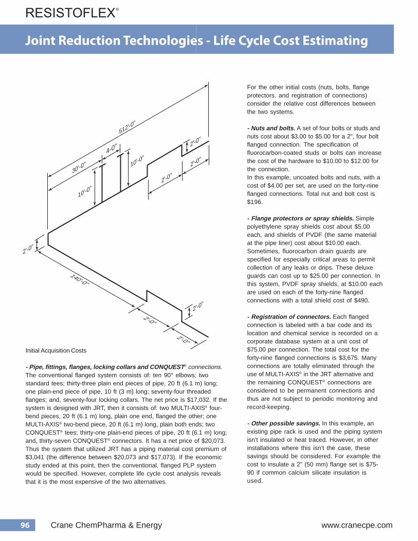
96 Crane ChemPharma & Energy www.cranecpe.com
For the other initial costs (nuts, bolts, flangeprotectors, and registration of connections)consider the relative cost differences betweenthe two systems.
- Nuts and bolts. A set of four bolts or studs andnuts cost about $3.00 to $5.00 for a 2", four boltflanged connection. The specification offluorocarbon-coated studs or bolts can increasethe cost of the hardware to $10.00 to $12.00 forthe connection.In this example, uncoated bolts and nuts, with acost of $4.00 per set, are used on the forty-nineflanged connections. Total nut and bolt cost is$196.
- Flange protectors or spray shields. Simplepolyethylene spray shields cost about $5.00each, and shields of PVDF (the same materialat the pipe liner) cost about $10.00 each.Sometimes, fluorocarbon drain guards arespecified for especially critical areas to permitcollection of any leaks or drips. These deluxeguards can cost up to $25.00 per connection. Inthis system, PVDF spray shields, at $10.00 eachare used on each of the forty-nine flangedconnections with a total shield cost of $490.
- Registration of connectors. Each flangedconnection is labeled with a bar code and itslocation and chemical service is recorded on acorporate database system at a unit cost of$75.00 per connection. The total cost for theforty-nine flanged connections is $3,675. Manyconnections are totally eliminated through theuse of MULTI-AXIS® in the JRT alternative andthe remaining CONQUEST® connections areconsidered to be permanent connections andthus are not subject to periodic monitoring andrecord-keeping.
- Other possible savings. In this example, anexisting pipe rack is used and the piping systemisn’t insulated or heat traced. However, in otherinstallations where this isn’t the case, thesesavings should be considered. For example thecost to insulate a 2" (50 mm) flange set is $75-90 if common calcium silicate insulation isused.
Initial Acquisition Costs
- Pipe, fittings, flanges, locking collars and CONQUEST® connections. The conventional flanged system consists of: ten 90° elbows; two standard tees; thirty-three plain end pieces of pipe, 20 ft (6.1 m) long; one plain-end piece of pipe, 10 ft (3 m) long; seventy-four threaded flanges; and, seventy-four locking collars. The net price is $17,032. If the system is designed with JRT, then it consists of: two MULTI-AXIS ® four- bend pieces, 20 ft (6.1 m) long, plain one end, flanged the other; one MULTI-AXIS ® two-bend piece, 20 ft (6.1 m) long, plain both ends; two CONQUEST ® tees; thirty-one plain-end pieces of pipe, 20 ft (6.1 m) long; and, thirty-seven CONQUEST ® connectors. It has a net price of $20,073. Thus the system that utilized JRT has a piping material cost premium of $3,041 (the difference between $20,073 and $17,073). If the economic study ended at this point, then the conventional, flanged PLP system would be specified. However, complete life cycle cost analysis reveals that it is the most expensive of the two alternatives.
512'-0"
4-0"
10'-0"
10'-0"
30'-0"
2'-0"
140'-0"
2'-0"
2'-0"
2'-0"
2'-0"
2'-0"
2'-0"
Joint Reduction Technologies - Life Cycle Cost Estimating

97www.cranecpe.com Crane ChemPharma & Energy
PPLPdegnalFlanoitnevnoC seigolonhceTnoitcudeRtnioJ.svTRJdegnalF.ytQ ecirPtinU
$.txE$ecirP .ytQ ecirPtinU
$.txE$ecirP
stsoCnoitisiuqcAlaitinI
srotcennocdnasralloc,segnalf,sgnittif,epiP 06.130,7 51 5.270,02 59.040,3
noitcennocrofstlob&tu 9N 4 00.4 00.69 01 0.691- tiderc
srotcetorpegnal 9F 4 00.01 00.09 04 0.094- tiderc
noitcennocfonoitartsige 9R 4 00.57 00.576, 03 0.576,3- tiderc
.ytQ tinUsruoH
.txEsruoH .ytQ tinU
sruoH.txEsruoH
sruoh,robaLnoitisiuqcAlaitinI
loopsepipdegnalfrofrh51.1noitacirbafdlei 7F 3 51.1 55.24
TSEUQNOCrofrh6.0noitacirbafdleiFnoitcennoc 73 06.0 2.22
noitcennocreprh4.0sdleihs,stlob,stunllatsn 9I 4 04.0 06.91
noitcennocreprh2.0,euqroterrh4 92 4 02.0 08.9
sruoHlatoT 59.1 27 .22
PLPlanoitnevnoCrofsruoHartxE 57.54
PPLPdegnalFlanoitnevnoC seigolonhceTnoitcudeRtnioJ.svTRJdegnalF.ytQ ecirPtinU
$.txE$ecirP .ytQ ecirPtinU
$.txE$ecirP
robaLnoitisiuqcAlaitinIrh/05$@sruohartxE 57.94 00.05 05.784, 02 5.784,2- tiderc
robaLdnaslairetaMnoitisiuqcAlaitinIfotsoCniecnereffiD 55.708,3- tiderc
stsoCecnanetniaMdnagnitarepOlaunnA
noitcennocdrocer&rotino 9M 4 00.57 00.576, 03 0.576,3- tiderc
noitcennoceuqrote 9R 4 00.01 00.09 04 0.094- tiderc
ecnereffiDtsoCgnitarepOlaunnA 00.561,4- tiderc
Discussion of results
It isn’t until the installation hardware (nuts, bolts, sprayshields) and labor is considered that the truly “less expensive”alternative is revealed. A JRT system costs about $3,800 lessto purchase, install and commission than does the same
The recurring annual cost savings realized by elimination of bolting hardware, monitoring, retorquing and record-keeping make the JRTsystem $4,165 less expensive to operate each year. This can create a cost savings of tens of thousands of dollars over thesystem, more than paying for the initial investment.
Obviously, each piping system is different and operating conditions are sometimes difficult to predict. As this studyquick answer to the question, “How much more will it cost me to use JRT?” The answer is “it depends”, and it’s usually
tional PLP when all costs associated with installation and maintenance are considered.to use JRT instead of conven
life of the
shows, there’s no less expensive
Joint Reduction Technologies - Life Cycle Cost Estimating

98 Crane ChemPharma & Energy www.cranecpe.com
Pressure Drop
Pressure drop per 100 Feet of Straight Resistoflex Plastic-Lined Pipe
FITTINGS
For pressure drops in fittings, please refer to a Piping Hand-book giving that information for unlined components inequivalent feet of pipe. Then use the pressure drop chart forPTFE lined pipe.
Note: The information on this page is intended to give a general ideaof pressure drop for plastic-lined pipe. For actual pressure dropcalculations used to size pumps or piping, use published formulasfrom recognized sources, such as Crane Technical Paper 410,which is also available as software.
0.01
0.1
1
10
100
1 10
1"1 1/2"2"3"4"
Velocity (feet per sec)
Pre
ssur
e D
rop
(PS
I per
100
ft. s
traig
ht p
ipe)
6"8"10"12"
Velocity (feet per sec)
Pre
ssur
e D
rop
(PS
I per
100
ft. s
traig
ht p
ipe)
0.01
0.1
1
10
1 10
PTFE Lined Pipe Pressure Drop Water at 60°F
INSTRUCTIONS FOR USE
1) You must know the flowrate in gallons per minute (gpm), or the velocity in feet per second (fps).
2) If you know the velocity in fps, go directly to the charts and locate the pressure drop for the velocity and line size you are working with.
3) If you don’t know the velocity, but know the flowrate in gpm, follow the example below to determine velocity in fps:
Note: CF factors were determined using the average ID’s of Resistoflex lined pipe for PTFE, PP, and PVDF liners.
Example:
What is the pressure drop in 2” pipe at 60 gpm? First multiply 60 gpm x 0.1322 (CF factor for 2”) to get a velocity of 7.93 feet per second. Look up the pressure drop for that velocity and line size in the charts. The pressure drop is approx. 4.5 psi per 100 ft. of straight pipe.
If the resultant pressure drop is too high for your needs, repeat the procedure for the next higher line size, until you get a pressure drop that is suitable. Conversely, a smaller line size will result in higher pressure drop for a given flowrate.
Pressure drops were determined using the Chen equation. Average lined pipe I.D.’s were used together with friction factors obtained from the Moody Diagram. Per a study made for Resistoflex by Battelle Institute, the friction factors were derived using relative roughness factors for perfectly smooth pipes.
Size CF1” .69331.5” .24332” .13223” .05434” .03006” .01328” .007310” .004512” .0031
99www.cranecpe.com Crane ChemPharma & Energy
Flange Bolt Torquingfor Resistoflex Plastic-Lined Piping Products
Torquing
When assembling flange connections, always use a full complement of clean, new high strength A193-B7 bolting. If using stainless steel bolting, the bolts should be A320/A320M Class 2 B8 (304 SS) or Class 2 B8M (316 SS) with A 94/A194M Grade 8 or 8A Nuts (for 304 SS) or Grade 8M or 8MA (for 316 SS). If other bolting materials are used, the end user must ensure that the new bolting material strength properties exceed the calculated bolt stress values to be generated in making the piping connection.
1) Always use flat washers on both sides of the connection.
2) Tighten the flange bolts with a calibrated torque wrench. The recommended bolt torque values are shown in the tables on next pages. Note: For zinc-plated bolts, or with anti-seize compounds, the torque values will be different. Please contact Resistoflex for more information
3) Tighten the flange bolts with a torque wrench, using a “crisscross” pattern that alternately tightens the bolts located 180 degrees apart.
4) Using this pattern, tighten the bolts in 20% increments of the final bolt torque until 80% of final bolt torque has been achieved.
5) For tightening to the final torque values, tighten bolts seq-uentially clockwise once around the flange. This will help ensure that the bolts are evenly stressed.
6) Care should be taken to avoid over-torquing, which can cause damage to the plastic sealing surfaces.
NOTES:
Gaskets are not required at lined pipe and/or fittings connections.
When bolting together dissimilar materials, always tighten to the lowest recommended torque of the components in the joint. Using higher torques may cause excessive deformation of the “softer” material in the joint.
Install a 1/2” thick spacer between Resistoflex plastic-lined pipe or fittings and other plastic-lined components, if the diameters of the raised plastic faces are different, as is often the case with plastic-lined valves. Spacers should also be used when mating plastic-lined piping to unlined pipe, fittings, valves, pumps, etc.
Belleville washers may be used if properly engineered.
Retorquing
A retorque should be applied within 24 hours of the initial torque or after the first thermal cycle. This allows for seating of the plastic and for relaxation of the bolts. If the system is to perform at elevated temperatures, it is recommended that hot water be circulated at the maximum operating temperature of the process (if possible) for a minimum of 24 hours. This allows for the pipe system to experience one thermal cycle. After cool-down, retorquing of the system should be done. Torquing should only be done on the system in the ambient, cooled state, never while the process is at elevated temperature, or excessive force could be applied to the plastic faces. Never disassemble a flange joint in a hot system. Wait until the system has cooled to ambient temperature.
Hydrostatic Testing
Normally, after initial torque and retorque, a hydrostatic test should be performed following ANSI requirements. Experience has shown that if the above procedure has been followed very few, if any, of the flange joints may fail the hydrostatic test. If a flange joint does leak, first check the torque values, then tighten in 10% increments over the specified bolt torques until sealed. However, if 150% of the specified torque value is reached and the flange joint still leaks, stop and disassemble the flange joint. Something else is probably wrong such as a scratched plastic face. Only after the hydrostatic test has been successfully completed and any leaks corrected, can the pipeline be signed off and commissioned.
Annual retorquing
Retorquing should be considered at least annually thereafter, especially if the process line experiences elevated temperatures or extreme ambient temperature situations. Torquing should only be done on the system in the ambient, cooled state, never while the process is at elevated temperature or excessive force could be applied to the plastic faces.
Note: Resistoflex recommends the use of flat washers on both flanges.Note: Lightly oiled is considered lubrication with WD-40* or equivalent. Please contact us for guidance on torques for other bolting/lubrication systems, such as zinc-plated bolts, or bolts with anti-seize lubricants.Note:The maximum recommended torque values are suggested for lined systems operating at or near the maximum recommended pressures and temperatures. Systems operating under less severe conditions can, in general, experience leak-free performance using lower torque values. Additionally, when gaskets are used, we suggest comparing the torque values of the plastic-lined piping and the gasket, and using the lower torque value. For systems that will require frequent disassembly, we suggest using the minimum recommended torque value initially to avoid distortion of the plastic face. *WD-40 is a trademark of WD-40 Company, San Diego, CA USA
Flange Bolt Torquing
When using butterfly valves in a lined pipe system, spacers are recommended on each side of the valve to ensure the valve fully opens.Consult factory for dimensions of spacers for use with butterfly valves.

100 Crane ChemPharma & Energy www.cranecpe.com
ANSI Class 150 Systems - Lightly Oiled A193 Gr. B7 Bolts and A194 2H Nuts
Pipe SizeNPS (DN)
Bolt Torque, ft-lb per Bolt (Nm per bolt)
PP PVDF PTFE PFA
Min. Max. Min. Max. Min. Max. Min. Max.
1/2 (15) - - - - - - - - 6 (9) 11 (15) 9 (13) 14 (19)
3/4 (20) - - - - - - - - 9 (13) 16 (22) 14 (19) 20 (28)
1 (25) 13 (18) 17 (24) 17 (24) 21 (29) 8 (11) 13 (18) 12 (17) 17 (24)
1 1/2 (40) 31 (43) 41 (56) 41 (56) 50 (68) 19 (26) 31 (43) 28 (38) 41 (56)
2 (50) 65 (89) 85 (116) 85 (116) 104 (142) 39 (53) 65 (89) 59 (81) 85 (116)
3 (80) 103 (140) 134 (182) 134 (182) 165 (224) 62 (85) 103 (140) 93 (127) 134 (182)
4 (100) 67 (91) 88 (120) 88 (120) 108 (147) 40 (55) 67 (91) 61 (83) 88 (120)
6 (150) 124 (169) 161 (219) 161 (219) 199 (270) 75 (102) 124 (169) 112 (152) 161 (219)
8 (200) 167 (227) 217 (295) 217 (295) 267 (363) 100 (136) 167 (227) - - - -
10 (250) 157 (213) 204 (277) 205 -277 252 (342) 157 (213) 204 (277) - - - -
12 (300) 193 (262) 251 (341) - - - - 193 (262) 251 (341) - - - -
14 (350) 258 (351) 336 (457) - - - - 155 (211) 259 (352) - - - -
16 (400) 236 (321) 307 (418) - - - - 142 (193) 237 (322) - - - -
18 (450) - - - - - - - - 192 (261) 320 (434) - - - -
20 (500) - - - - - - - - 167 (226) 278 (377) - - - -
24 (600) - - - - - - - - 214 (291) 358 (486) - - - -
ANSI Class 300 Systems - Lightly Oiled A193 Gr. B7 Bolts and A194 2H Nuts
Pipe SizeNPS (DN)
Bolt Torque, ft-lb per Bolt (Nm per bolt)
PP PVDF PTFE PFA
Min. Max. Min. Max. Min. Max. Min. Max.
1/2 (15) - - - - - - - - 6 (9) 11 (15) 9 (13) 14 (19)
3/4 (20) - - - - - - - - 6 (9) 10 (14) 9 (13) 13 (18)
1 (25) 17 (24) 22 (24) 22 (30) 27 (37) 10 (14) 17 (24) 15 (21) 22 (30)
1 1/2 (40) 47 (64) 61 (64) 61 (83) 75 (102) 28 (38) 47 (64) 42 (57) 61 (83)
2 (50) 33 (45) 42 (45) 42 (57) 52 (71) 20 (28) 33 (45) 29 (40) 42 (57)
3 (80) 62 (85) 80 (85) 80 (109) 99 (135) 37 (51) 62 (85) 56 (76) 80 (109)
4 (100) 81 (110) 105 (110) 105 (143) 130 (177) 49 (67) 81 (110) 73 (99) 105 (143)
6 (150) 83 (113) 108 (113) 108 (147) 132 (179) 50 (68) 83 (113) 75 (102) 108 (147)
8 (200) 130 (177) 169 (177) 169 (230) 207 (281) 78 (106) 130 (177) - - - -
10 (250) 135 (184) 175 (184) 176 (239) 216 (293) 135 (184) 175 (238) - - - -
12 (300) 186 (253) 242 (253) - - - - 186 (253) 242 (329) - - - -
14 (350) 174 (237) 226 (307) - - - - 105 (143) 175 (238) - - - -
16 (400) 236 (321) 307 (418) - - - - 142 (193) 237 (322) - - - -
18 (450) - - - - - - - - 143 (194) 237 (322) - - - -
20 (500) - - - - - - - - 155 (211) 257 (349) - - - -
24 (600) - - - - - - - - 215 (292) 358 (486) - - - -
Bolt Torque Chart
Note: These maximum torques are valid only for LIGHTLY OILED A193 Gr. B7 bolts. Lightly oiled is considered lubrication with WD-40® or equivalent. Contact the factory for bolt torque values when using anti-seize compounds. WD-40 is a trademark of WD-40 Company.
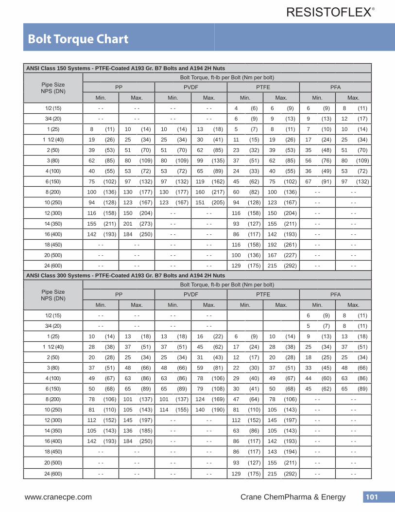
101www.cranecpe.com Crane ChemPharma & Energy
ANSI Class 150 Systems - Lightly Oiled A193 Gr. B7 Bolts and A194 2H Nuts
Pipe SizeNPS (DN)
Bolt Torque, ft-lb per Bolt (Nm per bolt)
PP PVDF PTFE PFA
Min. Max. Min. Max. Min. Max. Min. Max.
1/2 (15) - - - - - - - - 6 (9) 11 (15) 9 (13) 14 (19)
3/4 (20) - - - - - - - - 9 (13) 16 (22) 14 (19) 20 (28)
1 (25) 13 (18) 17 (24) 17 (24) 21 (29) 8 (11) 13 (18) 12 (17) 17 (24)
1 1/2 (40) 31 (43) 41 (56) 41 (56) 50 (68) 19 (26) 31 (43) 28 (38) 41 (56)
2 (50) 65 (89) 85 (116) 85 (116) 104 (142) 39 (53) 65 (89) 59 (81) 85 (116)
3 (80) 103 (140) 134 (182) 134 (182) 165 (224) 62 (85) 103 (140) 93 (127) 134 (182)
4 (100) 67 (91) 88 (120) 88 (120) 108 (147) 40 (55) 67 (91) 61 (83) 88 (120)
6 (150) 124 (169) 161 (219) 161 (219) 199 (270) 75 (102) 124 (169) 112 (152) 161 (219)
8 (200) 167 (227) 217 (295) 217 (295) 267 (363) 100 (136) 167 (227) - - - -
10 (250) 157 (213) 204 (277) 205 -277 252 (342) 157 (213) 204 (277) - - - -
12 (300) 193 (262) 251 (341) - - - - 193 (262) 251 (341) - - - -
14 (350) 258 (351) 336 (457) - - - - 155 (211) 259 (352) - - - -
16 (400) 236 (321) 307 (418) - - - - 142 (193) 237 (322) - - - -
18 (450) - - - - - - - - 192 (261) 320 (434) - - - -
20 (500) - - - - - - - - 167 (226) 278 (377) - - - -
24 (600) - - - - - - - - 214 (291) 358 (486) - - - -
ANSI Class 300 Systems - Lightly Oiled A193 Gr. B7 Bolts and A194 2H Nuts
Pipe SizeNPS (DN)
Bolt Torque, ft-lb per Bolt (Nm per bolt)
PP PVDF PTFE PFA
Min. Max. Min. Max. Min. Max. Min. Max.
1/2 (15) - - - - - - - - 6 (9) 11 (15) 9 (13) 14 (19)
3/4 (20) - - - - - - - - 6 (9) 10 (14) 9 (13) 13 (18)
1 (25) 17 (24) 22 (24) 22 (30) 27 (37) 10 (14) 17 (24) 15 (21) 22 (30)
1 1/2 (40) 47 (64) 61 (64) 61 (83) 75 (102) 28 (38) 47 (64) 42 (57) 61 (83)
2 (50) 33 (45) 42 (45) 42 (57) 52 (71) 20 (28) 33 (45) 29 (40) 42 (57)
3 (80) 62 (85) 80 (85) 80 (109) 99 (135) 37 (51) 62 (85) 56 (76) 80 (109)
4 (100) 81 (110) 105 (110) 105 (143) 130 (177) 49 (67) 81 (110) 73 (99) 105 (143)
6 (150) 83 (113) 108 (113) 108 (147) 132 (179) 50 (68) 83 (113) 75 (102) 108 (147)
8 (200) 130 (177) 169 (177) 169 (230) 207 (281) 78 (106) 130 (177) - - - -
10 (250) 135 (184) 175 (184) 176 (239) 216 (293) 135 (184) 175 (238) - - - -
12 (300) 186 (253) 242 (253) - - - - 186 (253) 242 (329) - - - -
14 (350) 174 (237) 226 (307) - - - - 105 (143) 175 (238) - - - -
16 (400) 236 (321) 307 (418) - - - - 142 (193) 237 (322) - - - -
18 (450) - - - - - - - - 143 (194) 237 (322) - - - -
20 (500) - - - - - - - - 155 (211) 257 (349) - - - -
24 (600) - - - - - - - - 215 (292) 358 (486) - - - -
Bolt Torque Chart
ANSI Class 150 Systems - PTFE-Coated A193 Gr. B7 Bolts and A194 2H Nuts
Pipe SizeNPS (DN)
Bolt Torque, ft-lb per Bolt (Nm per bolt)
PP PVDF PTFE PFA
Min. Max. Min. Max. Min. Max. Min. Max.
1/2 (15) - - - - - - - - 4 (6) 6 (9) 6 (9) 8 (11)
3/4 (20) - - - - - - - - 6 (9) 9 (13) 9 (13) 12 (17)
1 (25) 8 (11) 10 (14) 10 (14) 13 (18) 5 (7) 8 (11) 7 (10) 10 (14)
1 1/2 (40) 19 (26) 25 (34) 25 (34) 30 (41) 11 (15) 19 (26) 17 (24) 25 (34)
2 (50) 39 (53) 51 (70) 51 (70) 62 (85) 23 (32) 39 (53) 35 (48) 51 (70)
3 (80) 62 (85) 80 (109) 80 (109) 99 (135) 37 (51) 62 (85) 56 (76) 80 (109)
4 (100) 40 (55) 53 (72) 53 (72) 65 (89) 24 (33) 40 (55) 36 (49) 53 (72)
6 (150) 75 (102) 97 (132) 97 (132) 119 (162) 45 (62) 75 (102) 67 (91) 97 (132)
8 (200) 100 (136) 130 (177) 130 (177) 160 (217) 60 (82) 100 (136) - - - -
10 (250) 94 (128) 123 (167) 123 (167) 151 (205) 94 (128) 123 (167) - - - -
12 (300) 116 (158) 150 (204) - - - - 116 (158) 150 (204) - - - -
14 (350) 155 (211) 201 (273) - - - - 93 (127) 155 (211) - - - -
16 (400) 142 (193) 184 (250) - - - - 86 (117) 142 (193) - - - -
18 (450) - - - - - - - - 116 (158) 192 (261) - - - -
20 (500) - - - - - - - - 100 (136) 167 (227) - - - -
24 (600) - - - - - - - - 129 (175) 215 (292) - - - -
ANSI Class 300 Systems - PTFE-Coated A193 Gr. B7 Bolts and A194 2H Nuts
Pipe SizeNPS (DN)
Bolt Torque, ft-lb per Bolt (Nm per bolt)
PP PVDF PTFE PFA
Min. Max. Min. Max. Min. Max. Min. Max.
1/2 (15) - - - - - - - - 6 (9) 8 (11)
3/4 (20) - - - - - - - - 5 (7) 8 (11)
1 (25) 10 (14) 13 (18) 13 (18) 16 (22) 6 (9) 10 (14) 9 (13) 13 (18)
1 1/2 (40) 28 (38) 37 (51) 37 (51) 45 (62) 17 (24) 28 (38) 25 (34) 37 (51)
2 (50) 20 (28) 25 (34) 25 (34) 31 (43) 12 (17) 20 (28) 18 (25) 25 (34)
3 (80) 37 (51) 48 (66) 48 (66) 59 (81) 22 (30) 37 (51) 33 (45) 48 (66)
4 (100) 49 (67) 63 (86) 63 (86) 78 (106) 29 (40) 49 (67) 44 (60) 63 (86)
6 (150) 50 (68) 65 (89) 65 (89) 79 (108) 30 (41) 50 (68) 45 (62) 65 (89)
8 (200) 78 (106) 101 (137) 101 (137) 124 (169) 47 (64) 78 (106) - - - -
10 (250) 81 (110) 105 (143) 114 (155) 140 (190) 81 (110) 105 (143) - - - -
12 (300) 112 (152) 145 (197) - - - - 112 (152) 145 (197) - - - -
14 (350) 105 (143) 136 (185) - - - - 63 (86) 105 (143) - - - -
16 (400) 142 (193) 184 (250) - - - - 86 (117) 142 (193) - - - -
18 (450) - - - - - - - - 86 (117) 143 (194) - - - -
20 (500) - - - - - - - - 93 (127) 155 (211) - - - -
24 (600) - - - - - - - - 129 (175) 215 (292) - - - -
Bolt Torque Chart

102 Crane ChemPharma & Energy www.cranecpe.com
Class 150
Pipe SizeNPS (DN)
BoltSize Qty
Bolt Length, in. (mm) Stud Length, in. (mm)
F x F F x R R x R F x F F x R R x R
1/2 (15) 1/2 4 2 (51) 2 (51) 2 1/4 (57) 3 (76) 3 (76) 3 1/4 (83)
3/4 (20) 1/2 4 2 (51) 2 1/4 (57) 2 1/4 (57) 3 (76) 3 1/4 (83) 3 1/4 (83)
1 (25) 1/2 4 2 1/4 (57) 2 1/2 (64) 2 1/2 (64) 3 1/4 (83) 3 1/2 (89) 3 1/2 (89)
1 1/2 (40) 1/2 4 2 1/2 (64) 2 3/4 (70) 3 (76) 3 1/2 (89) 3 3/4 (95) 4 (102)
2 (50) 5/8 4 3 (76) 3 (76) 3 1/4 (83) 4 1/4 (108) 4 1/4 (108) 4 1/2 (114)
3 (80) 5/8 4 3 1/4 (83) 3 1/2 (89) 3 3/4 (95) 4 1/2 (114) 4 3/4 (121) 5 (127)
4 (100) 5/8 8 3 1/2 (89) 3 3/4 (95) 4 (102) 4 3/4 (121) 5 (127) 5 1/4 (133)
6 (150) 3/4 8 3 3/4 (95) 4 1/4 (108) 4 1/2 (114) 5 1/4 (133) 5 3/4 (146) 6 (152)
8 (200) 3/4 8 4 (102) 4 1/2 (114) 4 3/4 (121) 5 1/2 (140) 6 (152) 6 1/4 (159)
10 (250) 7/8 12 4 3/4 (121) 5 (127) 5 1/4 (133) 6 1/2 (165) 6 3/4 (171) 7 (178)
12 (300) 7/8 12 4 3/4 (121) 5 (127) 5 1/4 (133) 6 1/2 (165) 6 3/4 (171) 7 (178)
14 (350) 1 12 5 1/4 (133) 6 1/4 (159) 7 (178) 7 (178) 8 (203) 8 3/4 (222)
16 (400) 1 16 5 1/2 (140) 6 1/2 (165) 7 1/2 (191) 7 1/4 (184) 8 1/4 (210) 9 1/4 (235)
18 (450) 1 1/8 16 5 3/4 (146) 6 1/2 (165) 7 1/2 (191) 7 3/4 (197) 8 1/2 (216) 9 1/2 (241)
20 (500) 1 1/8 20 5 3/4 (146) 7 (178) 8 (203) 7 3/4 (197) 8 3/4 (222) 9 3/4 (248)
24 (600) 1 1/4 20 6 1/4 (159) 7 1/4 (184) 8 1/4 (210) 8 1/2 (216) 9 1/2 (241) 10 1/2 (267)
Class 300
Pipe SizeNPS (DN)
BoltSize Qty
Bolt Length, in. (mm) Stud Length, in. (mm)
F x F F x R R x R F x F F x R R x R
1/2 (15) 1/2 4 2 1/4 (57) 2 1/4 (57) 2 1/2 (64) 3 1/4 (83) 3 1/4 (83) 3 1/2 (89)
3/4 (20) 5/8 4 2 1/2 (64) 2 3/4 (70) 2 3/4 (70) 3 3/4 (95) 4 (102) 4 (102)
1 (25) 5/8 4 2 1/2 (64) 2 3/4 (70) 3 (76) 3 1/2 (89) 3 3/4 (95) 4 (102)
1 1/2 (40) 3/4 4 3 (76) 3 (76) 3 1/4 (83) 4 1/4 (108) 4 1/4 (108) 4 1/2 (114)
2 (50) 5/8 8 3 1/4 (83) 3 1/4 (83) 3 1/2 (89) 4 1/2 (114) 4 1/2 (114) 4 3/4 (121)
3 (80) 3/4 8 3 3/4 (95) 4 (102) 4 1/4 (108) 5 (127) 5 1/4 (133) 5 1/2 (140)
4 (100) 3/4 8 4 (102) 4 1/4 (108) 4 1/2 (114) 5 1/4 (133) 5 1/2 (140) 5 3/4 (146)
6 (150) 3/4 12 4 3/4 (121) 5 (127) 5 1/4 (133) 6 1/4 (159) 6 1/2 (165) 6 3/4 (171)
8 (200) 7/8 12 5 1/4 (133) 5 1/2 (140) 5 3/4 (146) 6 3/4 (171) 7 (178) 7 1/4 (184)
10 (250) 1 16 6 (152) 6 1/2 (165) 6 3/4 (171) 7 3/4 (197) 8 1/4 (210) 8 1/2 (216)
12 (300) 1 1/8 16 6 1/4 (159) 6 1/2 (165) 6 3/4 (171) 8 (203) 8 1/4 (305) 8 1/2 (305)
14 (350) 1 1/8 20 6 3/4 (171) 7 1/2 (191) 8 1/2 (216) 8 3/4 (222) 9 1/2 (241) 10 1/2 (267)
16 (400) 1 1/4 20 7 (178) 8 (203) 9 (229) 9 (229) 10 (254) 11 (279)
18 (450) 1 1/4 24 7 1/4 (184) 8 (203) 9 (229) 9 1/4 (235) 10 (254) 11 (279)
20 (500) 1 1/4 24 7 1/2 (191) 8 1/2 (216) 9 1/2 (241) 9 1/2 (241) 10 1/2 (267) 11 1/2 (292)
24 (600) 1 1/4 24 7 3/4 (197) 9 (229) 10 (254) 10 (254) 11 1/4 (286) 12 1/4 (311)
Bolt and Stud Lengths
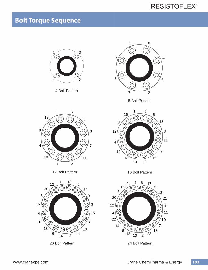
103www.cranecpe.com Crane ChemPharma & Energy
Bolt and Stud LengthsFLANGE BOLT TORQUE SEQUENCE
1
2
3
4
1
2
3
45
6
7
8
1
2
3
4
5
6
7
8
9
10 11
12
1
2
3
4
5
6
7
8
9
10
11
12
13
14
15
16
1
2
3
4
5
6
7
8 9
10
11
1213
14
15
16
17
18 19
20
1
2
3
4
5
67
8
9
10
11
12
13
1415
1617
18
19
20 21
22
23
24
4 Bolt Pattern
8 Bolt Pattern
12 Bolt Pattern 16 Bolt Pattern
20 Bolt Pattern 24 Bolt Pattern
Bolt Torque Sequence
104 Crane ChemPharma & Energy www.cranecpe.com
Pressure Testing Plastic-Lined Pipe
Hydrostatic Test
Resistoflex pipe and fittings can be tested at the pressures recommended by ASME B31.3. The fluid used for the hydrostatic test is typically water. Another suitable non-toxic liquid can be substituted if there is the risk of damage due to the adverse effects of having water in the system. The system should be tested at a pressure not less than 1.5 times the design pressure. If the design temperature is above the test temperature then the required test pressure is calculated by the following equation:
Pt = (1.5 PSt)/S
Where:
Pt = minimum hydrostatic test gauge pressure P = internal design gauge pressure St = allowable pipe stress value at test temperature S = allowable pipe stress value at design temperature
Typically, for the pressures and temperatures in which plastic- lined pipe is used, the above calculation reduces to:
Pt = 1.5 P
We recommend that the system be retorqued after the first thermocycle. If the hydrostatic test is performed at the ex- pected operating temperature (a “hot hydrotest”) then the hydrotest can constitute the first thermocycle and the recom- mended retorquing can occur after the pressure test.
Pneumatic Leak Test
This pressure test is performed in some situations where the presence of any water in the system is forbidden. The test is very dangerous due to the stored energy of the compressed gas. ASME B31.3 refers to the dangers of performing this test and provides safety considerations in the standard.
Test procedures should follow the requirements of ASME B31.3 Para 345.8 Sensitive Leak Test.
Alternative Leak Test
If a hydrostatic pressure test is undesirable due to the possible chemical reactions with water and a pneumatic test in undesir- able due to the potential hazards, then an alternative leak test can be used. This test is not applicable to plastic lined pipe because it relates to welded systems.
Initial Service Leak Test
This test is applicable only to systems, which meet the follow- ing requirements:
• The fluid handled is nonflammable, non-toxic, and not damaging ...to human tissues.
• The design gauge pressure does not exceed 150 psig.
• The design temperature is between -20°F and 366°F.
In this test, the test fluid is the service fluid. It is rare that this test is used with plastic-lined pipe. ASME B31.3 should be considered if more information concerning this test is required.
The above is a description of some pressure test methods. In general, most systems are hydrostatically tested as described in ASME B31.3. If the hydrostatic test is impractical, then the pneumatic test can be substituted, however, extreme caution must be observed during this potentially hazardous test.
Pressure Testing Plastic-Lined Pipe

105www.cranecpe.com Crane ChemPharma & Energy
Storage and MaintenanceStorage and Maintenance
Handling and Storing Plastic-Lined Pipe
To obtain maximum performance from Plastic-Lined Piping Products, it is important that the flared or molded end faces of the plastic are protected from damage during storage, handling and installation. The following should be considered when handling Plastic-Lined Piping Products:
• Store indoors or under cover. • Never put the lifts of a forklift inside of the pipe to transport. This can damage the plastic liner. • Products are shipped with a high performance, two component, epoxy primer protective coating. • Protective end caps are not designed for prolonged outdoor exposure. • Protective end caps on all pipe and fittings should be left in place until the pipe is ready to be installed. • Do not damage the plastic sealing faces when removing the end caps. • If end caps are removed for painting, they must be re-installed with bolting as soon as possible. • Avoid rough handling of plastic-lined pipe in temperatures below 40°F. Plastic becomes brittle in low temperatures,
and is more susceptible to cracking during rough handling. • Avoid mechanical or thermal shock to piping that is stored in cold temperatures. • Avoid storing plastic-lined piping products where they will be exposed to ultraviolet light for long periods of time. • The center of gravity of MULTI-AXIS® pipe may not be readily apparent. Be sure to handle carefully.
Safety Precautions for Field fabricating Plastic-Lined Pipe
Plastic-lined pipe can be fabricated on-site, and should only be fabricated by properly certified personnel. Please contact yourResistoflex representative for more information on certification training. When field fabricating plastic-lined pipe, adequate ventilation (such as exhaust fans) should be used. Overheating of the plastic can cause it to degrade and generate vapors. Avoid breathingvapors. Vapors can cause severe irritation to skin, eyes, and respiratory tract. When field fabricating, never heat the plastic with a torch or open flame.
Welding Plastic-Lined Piping Products During Field Fabrication
Welding should not be performed on Swaged plastic-lined pipe and fittings. Heat generated from welding will cause extensive damage to the plastic liners. If welding is necessary, use THERMALOK® plastic-lined pipe, since the liner can be moved back and out of the way from the heat source during welding. Any welding should be performed by a welder who is trained and certified to ASME Boiler and Vessel Code, Section IX. Plastic-lined pipe and fittings should not be used as a ground for electric welders or other equipment. NOTE: NEVER WELD ON FINISHED FLANGED PLASTIC LINED PIPE OR FITTINGS - LINER DAMAGE WILL RESULT.
Painting Plastic-Lined Piping Products
All pipe, fittings, and valves supplied by Resistoflex have a gray protective coating applied to minimize oxidation during shipping and handling. Refer to NACE guidelines and recommendations for sandblasting and selection of an appropriate primer and topcoat suitable for your plant environmental conditions.
It is important that the raised plastic face on all plastic-lined piping components is protected from damage during sandblastingand painting. Make sure that the protective end caps remain in place at all times during these operations, and direct the sandblasting away from the face of the flange. As an extra precaution, you may want to remove the protective end cap, apply protective tape over the plastic face, and then replace the cap before sandblasting and painting. If the exterior of the pipe is to treated with a heat-curable protective coating, exercise caution during the heating process. Never apply heat in excess of the liner’s maximum temperature rating.
PTFE venting collars on swaged pipe and vent holes on PTFE THERMALOK® pipe and PTFE-lined fittings should not be plugged with paint. The collars and holes are part of the venting system needed to prevent possible gas buildup behind the liner and
All paint systems have a poor resistance to handling and transit damage. This fact should be considered when evaluating pre-erection shop painting versus in-place painting. If shop painting is selected, touch-up will be required after job-site receipt. Touch-up costs are for Buyer’s account.
possible liner collapse. Pipe, fittings, and valves can also be special ordered without paint, but longer lead times may result.
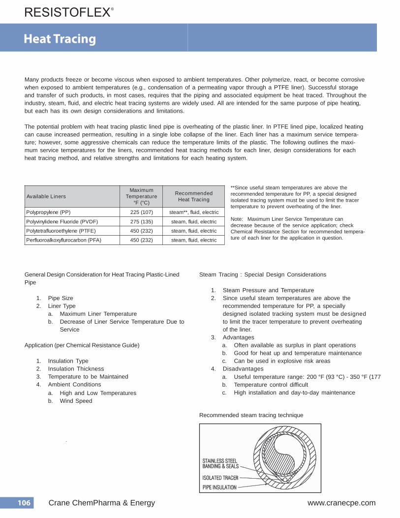
106 Crane ChemPharma & Energy www.cranecpe.com
Many products freeze or become viscous when exposed to ambient temperatures. Other polymerize, react, or become corrosive when exposed to ambient temperatures (e.g., condensation of a permeating vapor through a PTFE liner). Successful storage and transfer of such products, in most cases, requires that the piping and associated equipment be heat traced. Throughout the industry, steam, fluid, and electric heat tracing systems are widely used. All are intended for the same purpose of pipe heatin g, but each has its own design considerations and limitations.
The potential problem with heat tracing plastic lined pipe is overheating of the plastic liner. In PTFE lined pipe, localized h eating can cause increased permeation, resulting in a single lobe collapse of the liner. Each liner has a maximum service tempera- ture; however, some aggressive chemicals can reduce the temperature limits of the plastic. The following outlines the maxi- mum service temperatures for the liners, recommended heat tracing methods for each liner, design considerations for each heat tracing method, and relative strengths and limitations for each heating system.
**Since useful steam temperatures are above the recommended temperature for PP, a special designed isolated tracing system must be used to limit the tracer temperature to prevent overheating of the liner.
Note: Maximum Liner Service Temperature can decrease because of the service application; check Chemical Resistance Section for recommended tempera- ture of each liner for the application in question.
General Design Consideration for Heat Tracing Plastic-Lined Pipe
1. Pipe Size 2. Liner Type
a. Maximum Liner Temperature b. Decrease of Liner Service Temperature Due to
Service
Application (per Chemical Resistance Guide)
1. Insulation Type 2. Insulation Thickness 3. Temperature to be Maintained 4. Ambient Conditions
a. High and Low Temperatures b. Wind Speed
Steam Tracing : Special Design Considerations
1. Steam Pressure and Temperature 2. Since useful steam temperatures are above the
recommended temperature for PP, a specially designed isolated tracking system must be designed to limit the tracer temperature to prevent overheating of the liner.
3. Advantages
4. Disadvantages
a. Often available as surplus in plant operations b. Good for heat up and temperature maintenance c. Can be used in explosive risk areas
a. Useful temperature range: 200 °F (93 °C) - 350 °F (177 °C)b. Temperature control difficult c. High installation and day-to-day maintenance
Recommended steam tracing technique
s r e n i L e l b a l i a v A m u m i x a M
e r u t a r e p m e T ) C ° ( F °
d e d n e m m o c e R g n i c a r T t a e H
) P P ( e n e l y p o r p y l o P ) 7 0 1 ( 5 2 2 c i r t c e l e , d i u l f , * * m a e t s
) F D V P ( e d i r o u l F e n e d i l y n i v y l o P ) 5 3 1 ( 5 7 2 c i r t c e l e , d i u l f , m a e t s
) E F T P ( e n e l y h t e o r o u l f a r t e t y l o P ) 2 3 2 ( 0 5 4 c i r t c e l e , d i u l f , m a e t s
) A F P ( n o b r a c o r u l f y x o k l a o r o u l f r e P ) 2 3 2 ( 0 5 4 c i r t c e l e , d i u l f , m a e t s
Heat Tracing

107www.cranecpe.com Crane ChemPharma & Energy
Venting and InsulationPlastic-lined pipe is often insulated to prevent freezing, saveenergy or maintain a certain process temperature. Someoperating experience has shown that heat tracing andinsulating can also reduce permeation rates by lowering thetemperature differential across the pipe wall.
If installed improperly, however, insulation may block the pathsfor venting permeants on most PTFE-lined components.Under conditions which favor high permeation rates, blockageof the vent path can lead to high exterior steel shell corrosionrates, liner collapse and ultimately to premature failure of thelined components.
Swaged PTFE-lined pipe spools are designed to vent at theflange. Spiral grooves on the interior of the steel shell trans-port permeated vapors to the flange area, whereby they exit theannulus along a patented vent collar.
When insulating swaged PTFE-lined pipe spools and flangeconnections, care must be taken to extend the vent paththrough the insulation. One simple way is to drill a holethrough the bottom of the insulation and insert a piece of 1/4"flexible tubing into a position between the flanges. This isshown in Illustration A.
THERMALOK
Vent extenders can be metal or plastic. A PTFE hex plug designis increasingly being specified for insulated and uninsulated services. The end of the plug seats on the pipe OD con-centric with the vent hole, providing a corrosion-resistantpath for venting.
Example is shown below:
® PTFE-lined pipe and PTFE-lined fittings arevented via vent holes in the pipe, casting or fabricated steelshell. Welded half couplings and vent extenders can be usedto extend the vent path through insulation on pipe or aroundfittings, as shown in Illustration B & C. Couplings are availableas 3000lb. 1/8” or 1/4” sizes.
Venting Resistoflex plastic-lined pipe with Swaged pipe
A. Vent extender at insulated pipe joint
B. Vent holes and couplings on THERMALOK® pipe
C. Vent extender for fittings
L(specified by end user)
Material: PTFE
Insulation and Venting

Crane Resisto�exOne Quality Way
Marion, NC USA 28752Tel: +1 828 724 4000Fax: +1 828 724 4783
Crane Resisto�ex Australia146-154 Dunheved Circuit
St. Mary’s, NSW 2760Tel: 61 (2) 8889 0109Fax: 61 (2) 9673 3870
Crane Resisto�ex Middle East & AfricaThe Galleries - Building 4, Level 9
Dubai, UAE LOB 19Tel +971 4 816 5822
Fax: +971 4 816 5900
Crane Resisto�ex China33F Huaihai International Plaza,
1045 Central Huaihai RoadShanghai 200031
Tel: +86 21 6127 3000Fax: +86 21 6473 3688
Crane Resisto�ex Singapore16 Gul Link
Singapore 629386Tel: +65 6863 1559Fax: +65 6863 1560
Crane Resisto�ex EuropeCartografenweg 38 NL-5141MT
The NetherlandsTel +31 416 650286Fax +31 416 650874
CPE-
RESI
STO
FLEX
-DM
2016
-BU
-EN
-LT_
2017
_02_
23
Crane Co., and its subsidiaries cannot accept responsibility for possible errors in catalogues, brochures, other printed materials, and website information. Crane Co. reserves the right to alter its products without notice, including products already on order provided that such alteration can be made without changes being necessary in speci�cations already agreed. All trademarks in this material are property of the Crane Co. or its subsidiaries. The Crane and Crane brands logotype, in alphabetical order, (ALOYCO®, CENTER LINE®, COMPAC-NOZ®, CRANE®, DEPA®, DUO-CHEK®, ELRO®, FLOWSEAL®, JENKINS®, KROMBACH®, NOZ-CHEK®, PACIFIC VALVES®, RESISTOFLEX®, REVO®, SAUNDERS®, STOCKHAM®, TRIANGLE®, UNI-CHEK®, WTA®, and XOMOX®) are registered trademarks of Crane Co. All rights reserved.
brands you trust.
© Crane ChemPharma & Energy
®
www.flowoffluids.com
Crane ChemPharma & Energy
Per the Pressure Equipment Directive 97/23/EC Essential Safety Requirements Annex I Checklist, the following Essential Requirements are within the customer scope for all products: Wind, Earthquake, Reaction forces and Moments, Fire, Safety devices, permeation, temperature and pressure spikes. For all products, it is recommended that customer remove representative sample for examination of internal corrosion every 2 years.