design and installation guide -...
TRANSCRIPT
April 2014
Design and Installation Guide

2 APRIL 2014 WWW.NZWOODPRODUCTS.CO.NZ PH: 0800 022 352 DESIGN GUIDE
Scope of this Document ���������������������������������������������������������������4
Compliance ���������������������������������������������������������������������������������5
FSC & PEFC Chain of Custody Certification ������������������������������������6
Hyne Producer Statement ������������������������������������������������������������7
Pryda Producer Statement �����������������������������������������������������������8
David Reid - HD NZ Certification Letter �����������������������������������������9
David Reid - LPI Joists Certification Letter �����������������������������������10
Hyne Design Software ���������������������������������������������������������������11
I-Built Structural Components ����������������������������������������������������12
Product Summary ����������������������������������������������������������������������15
Structural Properties - LVL / LGL�������������������������������������������������16
LPI 70-T Structural Properties ����������������������������������������������������17
Typical Floor Construction Plan ���������������������������������������������������18
Floor Joist Span - LPI 70-T I-Beam ����������������������������������������������19
Floor Joist Span - Hyne LGL 44mm ���������������������������������������������20
Floor Joist Span - I-Built LVL 11 ��������������������������������������������������22
Floor Joist Span - I-Built LVL 13 ��������������������������������������������������23
Cantilever Floor Joist Details �������������������������������������������������������25
Cantilever Floor Joist Details / Fixing Details ��������������������������������26
Hanger Fixings���������������������������������������������������������������������������27
Internal Bracing & Web Stiffener Detail ���������������������������������������30
Boundary Details �����������������������������������������������������������������������31
Bracing and Blocking & Apron Roof Detail ������������������������������������32
J-Ply Floor Fixing – Details ����������������������������������������������������������33
Double Beam Connections ���������������������������������������������������������34
Holes in LP I-Beams �������������������������������������������������������������������35
Holes in LP I-Beams �������������������������������������������������������������������36
Service Holes Hyne Beam & Hyne LGL ����������������������������������������37
Overcoming Splitting / Taper Cuts - LGL, 17C & LVL ���������������������38
Standard Lintels, Defining Roof Load Width, I-Built J90 LVL ����������39
Standard Lintel - I-Built 90 LVL, I-Built LVL 13 �����������������������������40
Standard Lintel - Hyne LGL 44, I-Built LVL 11, Hyne Beam 17C �����41
Standard Lintel - Hyne Beam 17C �����������������������������������������������41
Roof Construction Plan ���������������������������������������������������������������42
Rafter Span - LPI 70-T I-Beam & Hyne LGL 44mm �����������������������43
Rafter Span - LPI 70-T I-Beam ����������������������������������������������������43
Rafter Span - Hyne LGL 44mm ���������������������������������������������������43
Rafter Span - I-Built LVL 13 - 45mm �������������������������������������������44
Rafter Span - I-Built LVL - 63mm ������������������������������������������������45
Roof Details �������������������������������������������������������������������������������46
Hanger Fixings���������������������������������������������������������������������������48
Avoid These Practices �����������������������������������������������������������������49
Storage, Handling and Safety �����������������������������������������������������50
Chemical Treatment of I-Beams, LGL Edgebeams, 17C, LVL, Rimboard & Plywood ������������������������������������������������������������������51
Contents
3APRIL 2014WWW.NZWOODPRODUCTS.CO.NZ PH: 0800 022 352DESIGN GUIDE
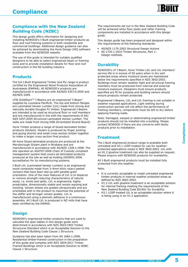
The span tables and construction details contained in this document have been developed primarily for domestic/residential applications in accordance with the principles and intent of NZS3604:2011 'Timber Framed Buildings'; NZS3603:1993 'Timber Structures Standard'; AS1720.1:2010 'Timber Structures – Design Methods'. Loading data is taken from AS/NZS1170:2002 'Structural Design Actions' to satisfy the requirements of Section B1 of the New Zealand Building Code.
All technical information and span tables in this guide are in accordance with the product specific design properties. This data may be used for specific engineering design in applications outside the scope of this document� Please refer to New Zealand Wood Products Ltd for the 'Engineering Data'.
The information in this design guide has been checked and verified, however, it should only be used by designers who are suitably qualified.
NZWOOD accepts no liability or responsibility if the information contained in this document is incorrectly interpreted, inappropriately applied, or used in a manner other than explicitly set out in this design guide.
Note: Other manufacturers’ products may have different properties and therefore cannot be substituted or designed using information contained in this document.
Scope of this Document
4 APRIL 2014 WWW.NZWOODPRODUCTS.CO.NZ PH: 0800 022 352 DESIGN GUIDE
Scop
e of this D
ocum
ent
Compliance with the New Zealand Building Code (NZBC)This design guide offers information for designing and installing NZWOOD’s I-Built engineered timber products as floor and roof framing systems in both residential and commercial buildings. Additional design guidance can also be achieved by downloading the Hyne Design (HD) software available from the NZWOOD website.
The use of this guide is intended for suitably qualified designers to be able to select engineered beam or framing sizes and to provide installation details for floor and roof construction in the NZ building industry.
ProductsThe full I-Built Engineered Timber and Ply range is product certified by the Engineered Wood Products Association of Australasia (EWPAA). All NZWOOD’s products are manufactured in accordance with AS/NZS 4357.0:2005 and AS/NZS 2269.
LP® SolidStart™ I-Beams are an engineered ‘I-Beam’ supplied by Louisiana Pacific®. The top and bottom flanges are Laminated Veneer Lumber (LVL) made from strong and naturally durable Douglas Fir timber. Engineered I-Beams are intended to be used as structural floor or roof members and are manufactured in line with the requirements of AS/NZS 4357:2005 Structural Laminated Veneer Lumber. The webs are made from strong OSB (Orientated Strand Board).
Hyne Timber produce a range of Glued-laminated timber products (Glulam). Glulam is produced by finger jointing and gluing shorter and small cross section timber together to make a larger cross section final product.
All Hyne Glued-laminated products are produced at the Maryborough Glulam plant in Brisbane and are manufactured in accordance with AS/NZS 1328.1:1998. The site operates an AS4707-2006 Chain of Custody compliant management system that covers all laminated products produced at the site as well as holding ISO9001:2006 accreditation for its manufacturing systems�
I-Built LVL (Laminated Veneer Lumber) is an engineered wood composite made from 3-4mm thick rotary peeled veneers that have been laid up with parallel grain orientation. One of the main features of LVL is to disperse or remove strength-reducing characteristics of natural wood, i.e. knots and splits. LVL is engineered, highly predictable, dimensionally stable and resists warping and twisting. Veneer sheets are graded ultrasonically and are orientated with in the product to maximise the potential of the stiffer and stronger veneer grades. LVL is manufactured using a phenolic adhesive in a continuous assembly. All I-Built LVL is produced in NZ mills that have been certified by the EWPAA.
DesignNZWOOD's engineered timber products that are used to calculate the span tables in this design guide were determined in accordance with NZS 3603:1993 Timber Structures Standard which is an Acceptable Solution to the New Zealand Building Code Clause 1 Structure.
Guidance has also been taken from AS 1684.1:1999, Residential timber-framed construction in the preparation of this guide and complies with NZS 3604:2011 Timber Framed Buildings which is an Acceptable Solution to NZBC Clause 1 Structure�
The requirements set out in the New Zealand Building Code will be achieved when floor joists and rafter framing components are installed in accordance with this design guide�
This design guide has been prepared and designed within the requirements of the following standards:
• AS/NZS 1170:2002 Structural Design Actions• AS 1720.1:2010 Timber Structures, Part 1:
Design methods�
DurabilityNZWOOD’s LP I-Beam, Hyne Timber LGL and LVL members’ service life is in excess of 50 years when in dry well protected areas where moisture levels are maintained below the requirements specified in NZS 3602:2003. Buildings must remain weather tight and structural framing members must be protected from internal and external moisture exposure. Designers must ensure products specified are fit for purpose and building owners should ensure products remain protected�
Engineered I-Beams, LGL and LVL framing is not suitable in weather exposed applications. Light wetting during construction periods will not affect the performance of framing members, components must be left to dry before applying framing loads�
Note: Damaged, warped or delaminating engineered timber products should not be installed into a building. Please contact NZWOOD if there are any concerns with faulty products prior to installation�
TreatmentThe I-Built engineered product range is available both untreated and H3.1 LOSP treated for use for weather-protected applications noted in NZS 3602:2003. LVL with an H1.2 glueline treatment can also be supplied on request. Please enquire with NZWOOD products for availability.
All I-Built engineered products must be installed fully protected from the weather�
Note:
• It is currently acceptable to install untreated engineered timber products in internal weather protected areas as defined by NZS 3602:2003.
• H1.2 LVL with glueline treatment is an acceptable solution for internal framing meeting the requirements of the New Zealand Building Code B2/AS1 for Durability.
• H3.1 LOSP treated LVL is an acceptable solution where it is being using in an H1.2 application.
Compliance
5
Com
plia
nce
APRIL 2014WWW.NZWOODPRODUCTS.CO.NZ PH: 0800 022 352DESIGN GUIDE
NZWOOD has Forest Stewardship Council® (FSC) and Programme for the Endorsement of Forest Certification (PEFC) chain of custody certification. The certification proves that the timber NZWOOD sells meets environmentally and socially responsible timber criteria. FSC and PEFC Chain of custody systems are governed by standards that require specific documentation and procedures for handling certified wood products with the basic aim to prevent the mixing of FSC or PEFC wood with uncontrolled sources� All information relating to the path taken by products from the forest including each stage of processing, transformation, manufacturing and distribution is tracked.
FSC Chain of Custody CertificationFSC chain of custody certified products provide assurances that the wood originates from well managed or responsibly managed forests. NZWOOD provide a range of plywood, scaffolding and LVL products that are FSC Certified with a FSC Mix 70% claim. Our main supplier for these products is Juken New Zealand Ltd.
PEFC Chain of Custody CertificationPEFC differs from FSC at the forest management level, but the chains of custody are similar. The certification includes requirements for traceability and handling of PEFC certified timber. A product carrying the PEFC label means it has originated from a forest certified by a PEFC endorsed scheme and has been handled by PEFC certified organisations. NZWOOD provide a range of I-Beams and engineered timber products that are PEFC certified. Our supplier of I-Beams is Louisiana Pacific Corporation and our supplier for engineered beams is Hyne Pty Australia.
If you require further information regarding our FSC and PEFC certification please contact us at NZWOOD.
PEFC CertifiedSGS-PEFC/COC-1437
FSC & PEFC Chain of Custody Certification
6 APRIL 2014 WWW.NZWOODPRODUCTS.CO.NZ PH: 0800 022 352 DESIGN GUIDE
FSC
& P
EFC C
hain
of Cu
stody C
ertification
HYNE TIMBER ABN 67 009 660 995
160 Kent St, PO Box 106
Maryborough QLD 4650
T: 07 4121 1211 F: 07 4122 4607
www.hyne.com.au
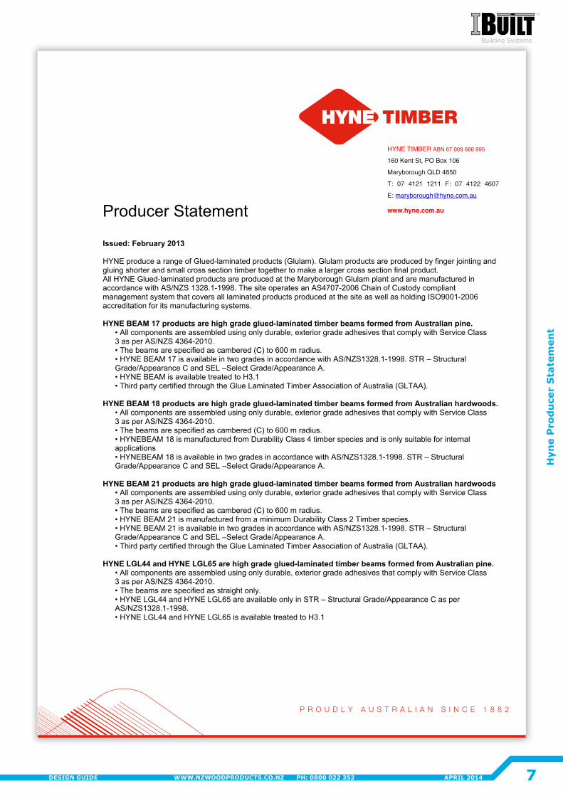
Producer Statement Issued: February 2013 HYNE produce a range of Glued-laminated products (Glulam). Glulam products are produced by finger jointing and gluing shorter and small cross section timber together to make a larger cross section final product. All HYNE Glued-laminated products are produced at the Maryborough Glulam plant and are manufactured in accordance with AS/NZS 1328.1-1998. The site operates an AS4707-2006 Chain of Custody compliant management system that covers all laminated products produced at the site as well as holding ISO9001-2006 accreditation for its manufacturing systems. HYNE BEAM 17 products are high grade glued-laminated timber beams formed from Australian pine.
• All components are assembled using only durable, exterior grade adhesives that comply with Service Class 3 as per AS/NZS 4364-2010. • The beams are specified as cambered (C) to 600 m radius. • HYNE BEAM 17 is available in two grades in accordance with AS/NZS1328.1-1998. STR – Structural Grade/Appearance C and SEL –Select Grade/Appearance A. • HYNE BEAM is available treated to H3.1 • Third party certified through the Glue Laminated Timber Association of Australia (GLTAA).
HYNE BEAM 18 products are high grade glued-laminated timber beams formed from Australian hardwoods.
• All components are assembled using only durable, exterior grade adhesives that comply with Service Class 3 as per AS/NZS 4364-2010. • The beams are specified as cambered (C) to 600 m radius. • HYNEBEAM 18 is manufactured from Durability Class 4 timber species and is only suitable for internal applications • HYNEBEAM 18 is available in two grades in accordance with AS/NZS1328.1-1998. STR – Structural Grade/Appearance C and SEL –Select Grade/Appearance A.
HYNE BEAM 21 products are high grade glued-laminated timber beams formed from Australian hardwoods
• All components are assembled using only durable, exterior grade adhesives that comply with Service Class 3 as per AS/NZS 4364-2010. • The beams are specified as cambered (C) to 600 m radius. • HYNE BEAM 21 is manufactured from a minimum Durability Class 2 Timber species. • HYNE BEAM 21 is available in two grades in accordance with AS/NZS1328.1-1998. STR – Structural Grade/Appearance C and SEL –Select Grade/Appearance A. • Third party certified through the Glue Laminated Timber Association of Australia (GLTAA).
HYNE LGL44 and HYNE LGL65 are high grade glued-laminated timber beams formed from Australian pine.
• All components are assembled using only durable, exterior grade adhesives that comply with Service Class 3 as per AS/NZS 4364-2010. • The beams are specified as straight only. • HYNE LGL44 and HYNE LGL65 are available only in STR – Structural Grade/Appearance C as per AS/NZS1328.1-1998. • HYNE LGL44 and HYNE LGL65 is available treated to H3.1
DESIGN GUIDE WWW.NZWOODPRODUCTS.CO.NZ PH: 0800 022 352 FEBRUARY 2014
7
Hyn
e P
rod
uce
r S
tate
men
t
APRIL 2014WWW.NZWOODPRODUCTS.CO.NZ PH: 0800 022 352DESIGN GUIDE
|
8
Pryd
a Prod
ucer S
tatemen
t
APRIL 2014 WWW.NZWOODPRODUCTS.CO.NZ PH: 0800 022 352 DESIGN GUIDE
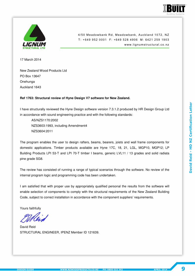
17 March 2014
New Zealand Wood Products Ltd
PO Box 13647
Onehunga
Auckland 1643
Ref 1763: Structural review of Hyne Design V7 software for New Zealand.
I have structurally reviewed the Hyne Design software version 7.3.1.2 produced by HR Design Group Ltd
in accordance with sound engineering practice and with the following standards:
AS/NZS1170:2002
NZS3603:1993, including Amendment4
NZS3604:2011
The program enables the user to design rafters, beams, bearers, joists and wall frame components for
domestic applications. Timber products available are Hyne 17C, 18, 21, LGL, MGP10, MGP12; LP
Building Products LPI 53-T and LPI 70-T timber I beams, generic LVL11 / 13 grades and solid radiata
pine grade SG8.
The review has consisted of running a range of typical scenarios through the software. No review of the
internal program logic and programming code has been undertaken.
I am satisfied that with proper use by appropriately qualified personal the results from the software will
enable selection of components to comply with the structural requirements of the New Zealand Building
Code, subject to correct installation in accordance with the component suppliers’ requirements.
Yours faithfully
David Reid
STRUCTURAL ENGINEER, IPENZ Member ID 121639.
9
Dav
id R
eid
- H
D N
Z C
erti
fica
tion
Let
ter
APRIL 2014WWW.NZWOODPRODUCTS.CO.NZ PH: 0800 022 352DESIGN GUIDE
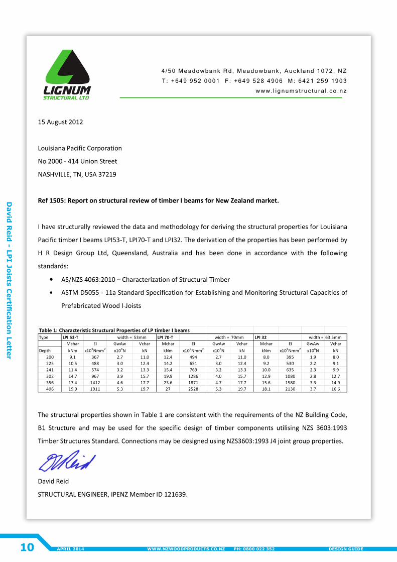
15 August 2012
Louisiana Pacific Corporation
No 2000 - 414 Union Street
NASHVILLE, TN, USA 37219
Ref 1505: Report on structural review of timber I beams for New Zealand market.
I have structurally reviewed the data and methodology for deriving the structural properties for Louisiana
Pacific timber I beams LPI53-T, LPI70-T and LPI32. The derivation of the properties has been performed by
H R Design Group Ltd, Queensland, Australia and has been done in accordance with the following
standards:
• AS/NZS 4063:2010 – Characterization of Structural Timber
• ASTM D5055 - 11a Standard Specification for Establishing and Monitoring Structural Capacities of
Prefabricated Wood I-Joists
Table 1: Characteristic Structural Properties of LP timber I beamsType LPI 53-T width = 53mm LPI 70-T width = 70mm LPI 32 width = 63.5mm
Mchar EI GwAw Vchar Mchar EI GwAw Vchar Mchar EI GwAw VcharDepth kNm x109Nmm2 x106N kN kNm x109Nmm2 x106N kN kNm x109Nmm2 x106N kN
200 9.1 367 2.7 11.0 12.4 494 2.7 11.0 8.0 395 1.9 8.0225 10.5 488 3.0 12.4 14.2 651 3.0 12.4 9.2 530 2.2 9.1241 11.4 574 3.2 13.3 15.4 769 3.2 13.3 10.0 635 2.3 9.9302 14.7 967 3.9 15.7 19.9 1286 4.0 15.7 12.9 1080 2.8 12.7356 17.4 1412 4.6 17.7 23.6 1871 4.7 17.7 15.6 1580 3.3 14.9406 19.9 1911 5.3 19.7 27 2528 5.3 19.7 18.1 2130 3.7 16.6
The structural properties shown in Table 1 are consistent with the requirements of the NZ Building Code,
B1 Structure and may be used for the specific design of timber components utilising NZS 3603:1993
Timber Structures Standard. Connections may be designed using NZS3603:1993 J4 joint group properties.
David Reid
STRUCTURAL ENGINEER, IPENZ Member ID 121639.
10
David
Reid
- LPI Joists C
ertification
Letter
APRIL 2014 WWW.NZWOODPRODUCTS.CO.NZ PH: 0800 022 352 DESIGN GUIDE

Hyne Design
Need to see more? Visit New Zealand Wood Products Limited (www.nzwoodproducts.co.nz) for a free programme download with just one click of a button.
Waiting for you on our website is the feature packed Hyne Design (HD) software, distributed in NZ by New Zealand Wood Products who are the Sole Distributors of the Hyne Timber Product Range. HD software can specify Louisiana Pacific’s Solid Start timber I-Beams for an engineered floor or rafter framing system, a range of LVL11 and LVL13 products, Hyne’s 17C, 18C and 21C high strength laminated beams and the Hyne 44mm LGL Edge beam. A range of common SG8 solid timber sizes are included also for additional design scope. NZWOOD will provide technical support and design services for these products as well as providing support with the HD software package.
11APRIL 2014WWW.NZWOODPRODUCTS.CO.NZ PH: 0800 022 352DESIGN GUIDE
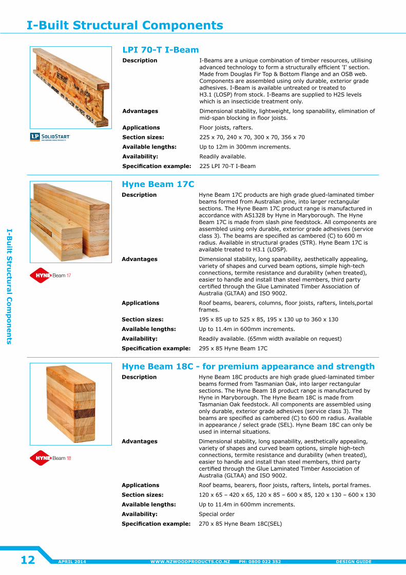
LPI 70-T I-BeamDescription I-Beams are a unique combination of timber resources, utilising
advanced technology to form a structurally efficient 'I' section. Made from Douglas Fir Top & Bottom Flange and an OSB web. Components are assembled using only durable, exterior grade adhesives. I-Beam is available untreated or treated to H3.1 (LOSP) from stock. I-Beams are supplied to H2S levels which is an insecticide treatment only�
Advantages Dimensional stability, lightweight, long spanability, elimination of mid-span blocking in floor joists.
Applications Floor joists, rafters.
Section sizes: 225 x 70, 240 x 70, 300 x 70, 356 x 70
Available lengths: Up to 12m in 300mm increments.
Availability: Readily available.
Specification example: 225 LPI 70-T I-Beam
Hyne Beam 17CDescription Hyne Beam 17C products are high grade glued-laminated timber
beams formed from Australian pine, into larger rectangular sections. The Hyne Beam 17C product range is manufactured in accordance with AS1328 by Hyne in Maryborough. The Hyne Beam 17C is made from slash pine feedstock. All components are assembled using only durable, exterior grade adhesives (service class 3). The beams are specified as cambered (C) to 600 m radius. Available in structural grades (STR). Hyne Beam 17C is available treated to H3.1 (LOSP).
Advantages Dimensional stability, long spanability, aesthetically appealing, variety of shapes and curved beam options, simple high-tech connections, termite resistance and durability (when treated), easier to handle and install than steel members, third party certified through the Glue Laminated Timber Association of Australia (GLTAA) and ISO 9002.
Applications Roof beams, bearers, columns, floor joists, rafters, lintels,portal frames�
Section sizes: 195 x 85 up to 525 x 85, 195 x 130 up to 360 x 130
Available lengths: Up to 11.4m in 600mm increments.
Availability: Readily available. (65mm width available on request)
Specification example: 295 x 85 Hyne Beam 17C
Hyne Beam 18C - for premium appearance and strengthDescription Hyne Beam 18C products are high grade glued-laminated timber
beams formed from Tasmanian Oak, into larger rectangular sections. The Hyne Beam 18 product range is manufactured by Hyne in Maryborough. The Hyne Beam 18C is made from Tasmanian Oak feedstock. All components are assembled using only durable, exterior grade adhesives (service class 3). The beams are specified as cambered (C) to 600 m radius. Available in appearance / select grade (SEL). Hyne Beam 18C can only be used in internal situations�
Advantages Dimensional stability, long spanability, aesthetically appealing, variety of shapes and curved beam options, simple high-tech connections, termite resistance and durability (when treated), easier to handle and install than steel members, third party certified through the Glue Laminated Timber Association of Australia (GLTAA) and ISO 9002.
Applications Roof beams, bearers, floor joists, rafters, lintels, portal frames.
Section sizes: 120 x 65 – 420 x 65, 120 x 85 – 600 x 85, 120 x 130 – 600 x 130
Available lengths: Up to 11.4m in 600mm increments.
Availability: Special order
Specification example: 270 x 85 Hyne Beam 18C(SEL)
I-Built Structural Components
12
I-Bu
ilt Stru
ctural C
omp
onen
ts
APRIL 2014 WWW.NZWOODPRODUCTS.CO.NZ PH: 0800 022 352 DESIGN GUIDE
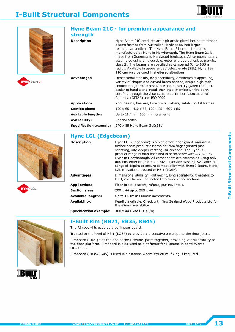
Hyne Beam 21C - for premium appearance and strengthDescription Hyne Beam 21C products are high grade glued-laminated timber
beams formed from Australian Hardwoods, into larger rectangular sections. The Hyne Beam 21 product range is manufactured by Hyne in Maryborough. The Hyne Beam 21 is made from Queensland Hardwood feedstock. All components are assembled using only durable, exterior grade adhesives (service class 3). The beams are specified as cambered (C) to 600m radius. Available in appearance / select grade (SEL). Hyne Beam 21C can only be used in sheltered situations.
Advantages Dimensional stability, long spanability, aesthetically appealing, variety of shapes and curved beam options, simple high-tech connections, termite resistance and durability (when treated), easier to handle and install than steel members, third party certified through the Glue Laminated Timber Association of Australia (GLTAA) and ISO 9002.
Applications Roof beams, bearers, floor joists, rafters, lintels, portal frames.
Section sizes: 120 x 65 – 410 x 65, 120 x 85 – 600 x 85
Available lengths: Up to 11.4m in 600mm increments.
Availability: Special order�
Specification example: 270 x 85 Hyne Beam 21C(SEL)
Hyne LGL (Edgebeam)Description Hyne LGL (Edgebeam) is a high grade edge glued-laminated
timber beam product assembled from finger jointed pine scantling, into deeper rectangular sections. The Hyne LGL product range is manufactured in accordance with AS1328 by Hyne in Maryborough. All components are assembled using only durable, exterior grade adhesives (service class 3). Available in a range of depths to ensure compatibility with Hyne-I-Beam. Hyne LGL is available treated or H3.1 (LOSP).
Advantages Dimensional stability, lightweight, long spanability, treatable to H3.1, may be nail-laminated to provide wider sections.
Applications Floor joists, bearers, rafters, purlins, lintels.
Section sizes: 200 x 44 up to 360 x 44
Available lengths: Up to 11.4m in 600mm increments.
Availability: Readily available. Check with New Zealand Wood Products Ltd for the 65mm availability.
Specification example: 300 x 44 Hyne LGL (E/B)
I-Built Rim (RB21, RB35, RB45)The Rimboard is used as a perimeter board.
Treated to the level of H3.1 (LOSP) to provide a protective envelope to the floor joists.
Rimboard (RB21) ties the end of the I-Beams joists together, providing lateral stability to the floor platform. Rimboard is also used as a stiffener for I-Beams in cantilevered situations�
Rimboard (RB35/RB45) is used in situations where structural fixing is required.
I-Built Structural Components
13
I-B
uilt
Str
uct
ura
l Com
pon
ents
APRIL 2014WWW.NZWOODPRODUCTS.CO.NZ PH: 0800 022 352DESIGN GUIDE
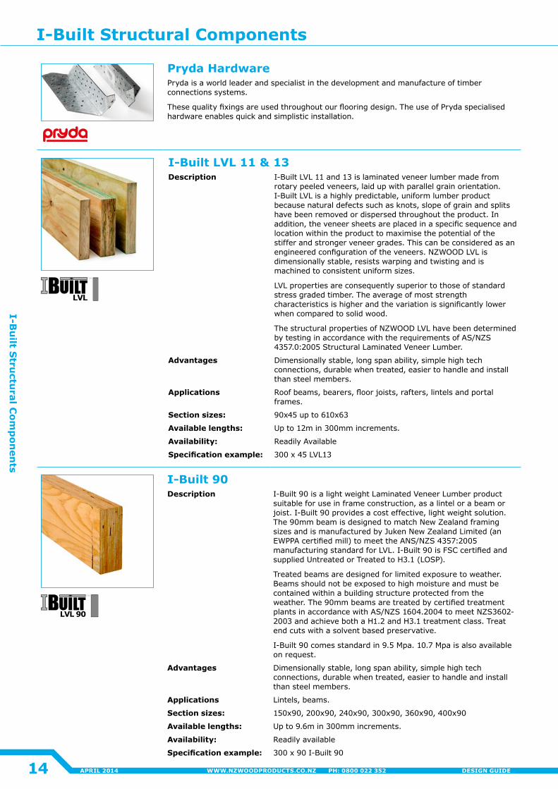
Pryda HardwarePryda is a world leader and specialist in the development and manufacture of timber connections systems�
These quality fixings are used throughout our flooring design. The use of Pryda specialised hardware enables quick and simplistic installation.
I-Built LVL 11 & 13Description I-Built LVL 11 and 13 is laminated veneer lumber made from
rotary peeled veneers, laid up with parallel grain orientation. I-Built LVL is a highly predictable, uniform lumber product because natural defects such as knots, slope of grain and splits have been removed or dispersed throughout the product. In addition, the veneer sheets are placed in a specific sequence and location within the product to maximise the potential of the stiffer and stronger veneer grades. This can be considered as an engineered configuration of the veneers. NZWOOD LVL is dimensionally stable, resists warping and twisting and is machined to consistent uniform sizes�
LVL properties are consequently superior to those of standard stress graded timber. The average of most strength characteristics is higher and the variation is significantly lower when compared to solid wood�
The structural properties of NZWOOD LVL have been determined by testing in accordance with the requirements of AS/NZS 4357.0:2005 Structural Laminated Veneer Lumber.
Advantages Dimensionally stable, long span ability, simple high tech connections, durable when treated, easier to handle and install than steel members.
Applications Roof beams, bearers, floor joists, rafters, lintels and portal frames�
Section sizes: 90x45 up to 610x63
Available lengths: Up to 12m in 300mm increments.
Availability: Readily Available
Specification example: 300 x 45 LVL13
I-Built 90Description I-Built 90 is a light weight Laminated Veneer Lumber product
suitable for use in frame construction, as a lintel or a beam or joist. I-Built 90 provides a cost effective, light weight solution. The 90mm beam is designed to match New Zealand framing sizes and is manufactured by Juken New Zealand Limited (an EWPPA certified mill) to meet the ANS/NZS 4357:2005 manufacturing standard for LVL. I-Built 90 is FSC certified and supplied Untreated or Treated to H3.1 (LOSP).
Treated beams are designed for limited exposure to weather. Beams should not be exposed to high moisture and must be contained within a building structure protected from the weather. The 90mm beams are treated by certified treatment plants in accordance with AS/NZS 1604.2004 to meet NZS3602- 2003 and achieve both a H1.2 and H3.1 treatment class. Treat end cuts with a solvent based preservative.
I-Built 90 comes standard in 9.5 Mpa. 10.7 Mpa is also available on request�
Advantages Dimensionally stable, long span ability, simple high tech connections, durable when treated, easier to handle and install than steel members.
Applications Lintels, beams.
Section sizes: 150x90, 200x90, 240x90, 300x90, 360x90, 400x90
Available lengths: Up to 9.6m in 300mm increments.
Availability: Readily available
Specification example: 300 x 90 I-Built 90
I-Built Structural Components
14
I-Bu
ilt Stru
ctural C
omp
onen
ts
APRIL 2014 WWW.NZWOODPRODUCTS.CO.NZ PH: 0800 022 352 DESIGN GUIDE
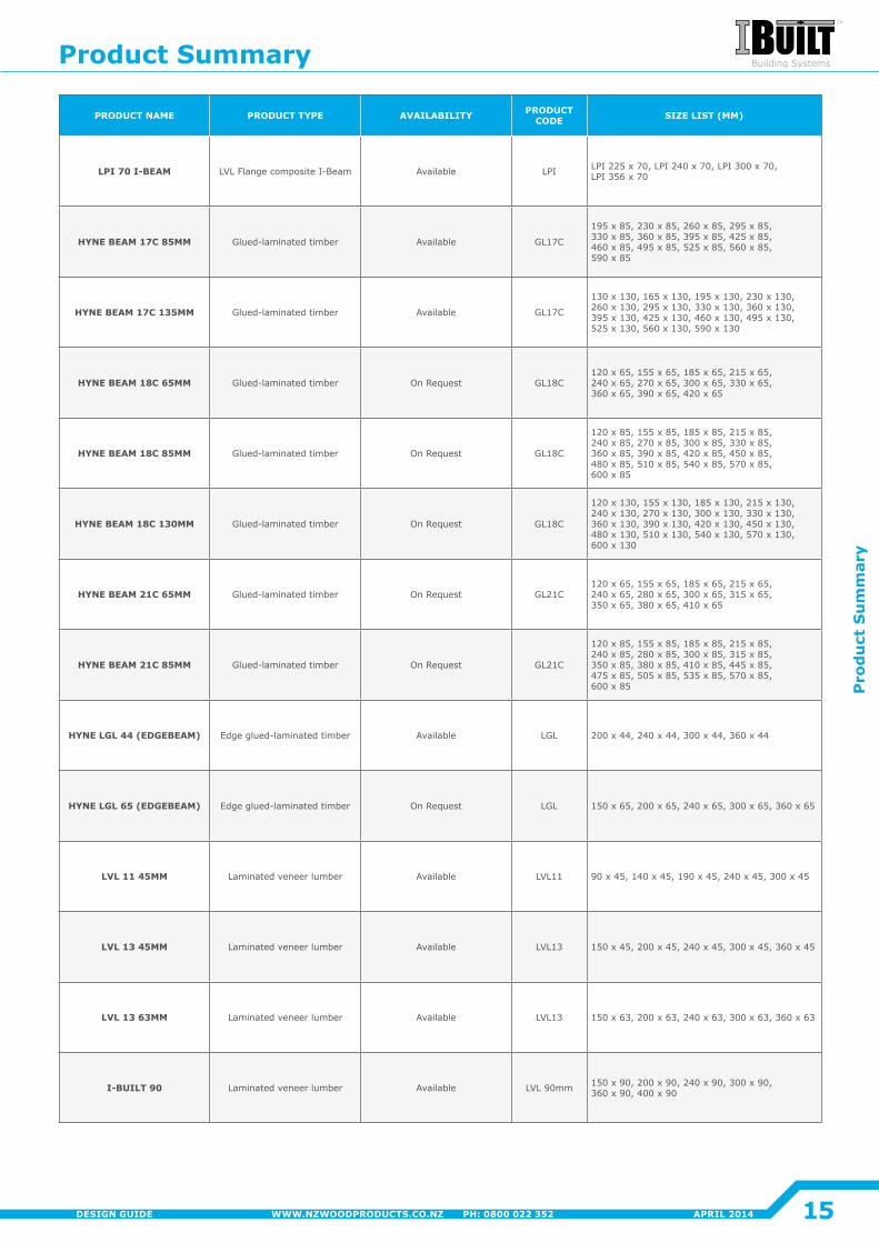
PRODUCT NAME PRODUCT TYPE AVAILABILITY PRODUCT CODE SIZE LIST (MM)
LPI 70 I-BEAM LVL Flange composite I-Beam Available LPI LPI 225 x 70, LPI 240 x 70, LPI 300 x 70, LPI 356 x 70
HYNE BEAM 17C 85MM Glued-laminated timber Available GL17C
195 x 85, 230 x 85, 260 x 85, 295 x 85, 330 x 85, 360 x 85, 395 x 85, 425 x 85, 460 x 85, 495 x 85, 525 x 85, 560 x 85, 590 x 85
HYNE BEAM 17C 135MM Glued-laminated timber Available GL17C
130 x 130, 165 x 130, 195 x 130, 230 x 130, 260 x 130, 295 x 130, 330 x 130, 360 x 130, 395 x 130, 425 x 130, 460 x 130, 495 x 130, 525 x 130, 560 x 130, 590 x 130
HYNE BEAM 18C 65MM Glued-laminated timber On Request GL18C120 x 65, 155 x 65, 185 x 65, 215 x 65, 240 x 65, 270 x 65, 300 x 65, 330 x 65, 360 x 65, 390 x 65, 420 x 65
HYNE BEAM 18C 85MM Glued-laminated timber On Request GL18C
120 x 85, 155 x 85, 185 x 85, 215 x 85, 240 x 85, 270 x 85, 300 x 85, 330 x 85, 360 x 85, 390 x 85, 420 x 85, 450 x 85, 480 x 85, 510 x 85, 540 x 85, 570 x 85, 600 x 85
HYNE BEAM 18C 130MM Glued-laminated timber On Request GL18C
120 x 130, 155 x 130, 185 x 130, 215 x 130, 240 x 130, 270 x 130, 300 x 130, 330 x 130, 360 x 130, 390 x 130, 420 x 130, 450 x 130, 480 x 130, 510 x 130, 540 x 130, 570 x 130, 600 x 130
HYNE BEAM 21C 65MM Glued-laminated timber On Request GL21C120 x 65, 155 x 65, 185 x 65, 215 x 65, 240 x 65, 280 x 65, 300 x 65, 315 x 65, 350 x 65, 380 x 65, 410 x 65
HYNE BEAM 21C 85MM Glued-laminated timber On Request GL21C
120 x 85, 155 x 85, 185 x 85, 215 x 85, 240 x 85, 280 x 85, 300 x 85, 315 x 85, 350 x 85, 380 x 85, 410 x 85, 445 x 85, 475 x 85, 505 x 85, 535 x 85, 570 x 85, 600 x 85
HYNE LGL 44 (EDGEBEAM) Edge glued-laminated timber Available LGL 200 x 44, 240 x 44, 300 x 44, 360 x 44
HYNE LGL 65 (EDGEBEAM) Edge glued-laminated timber On Request LGL 150 x 65, 200 x 65, 240 x 65, 300 x 65, 360 x 65
LVL 11 45MM Laminated veneer lumber Available LVL11 90 x 45, 140 x 45, 190 x 45, 240 x 45, 300 x 45
LVL 13 45MM Laminated veneer lumber Available LVL13 150 x 45, 200 x 45, 240 x 45, 300 x 45, 360 x 45
LVL 13 63MM Laminated veneer lumber Available LVL13 150 x 63, 200 x 63, 240 x 63, 300 x 63, 360 x 63
I-BUILT 90 Laminated veneer lumber Available LVL 90mm 150 x 90, 200 x 90, 240 x 90, 300 x 90, 360 x 90, 400 x 90
Product Summary
15
Pro
du
ct S
um
mar
y
APRIL 2014WWW.NZWOODPRODUCTS.CO.NZ PH: 0800 022 352DESIGN GUIDE
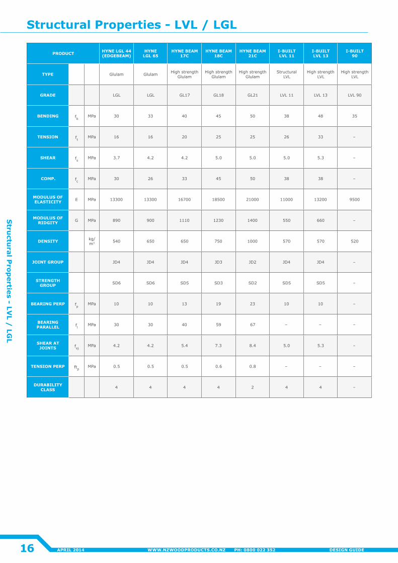
PRODUCT HYNE LGL 44 (EDGEBEAM)
HYNE LGL 65
HYNE BEAM 17C
HYNE BEAM 18C
HYNE BEAM 21C
I-BUILT LVL 11
I-BUILT LVL 13
I-BUILT90
TYPE Glulam Glulam High strength Glulam
High strength Glulam
High strength Glulam
Structural LVL
High strength LVL
High strength LVL
GRADE LGL LGL GL17 GL18 GL21 LVL 11 LVL 13 LVL 90
BENDING fb MPa 30 33 40 45 50 38 48 35
TENSION ft MPa 16 16 20 25 25 26 33 –
SHEAR fs MPa 3.7 4�2 4�2 5.0 5.0 5.0 5.3 –
COMP. fc MPa 30 26 33 45 50 38 38 –
MODULUS OF ELASTICITY E MPa 13300 13300 16700 18500 21000 11000 13200 9500
MODULUS OF RIDGITY G MPa 890 900 1110 1230 1400 550 660 –
DENSITY kg/m3 540 650 650 750 1000 570 570 520
JOINT GROUP JD4 JD4 JD4 JD3 JD2 JD4 JD4 –
STRENGTH GROUP SD6 SD6 SD5 SD3 SD2 SD5 SD5 –
BEARING PERP fp MPa 10 10 13 19 23 10 10 –
BEARING PARALLEL fl MPa 30 30 40 59 67 – – –
SHEAR AT JOINTS fsj MPa 4�2 4�2 5.4 7.3 8.4 5.0 5.3 –
TENSION PERP ftp MPa 0.5 0.5 0.5 0.6 0.8 – – –
DURABILITY CLASS 4 4 4 4 2 4 4 –
Structural Properties - LVL / LGL
16
Stru
ctural P
roperties - LV
L / LG
L
APRIL 2014 WWW.NZWOODPRODUCTS.CO.NZ PH: 0800 022 352 DESIGN GUIDE
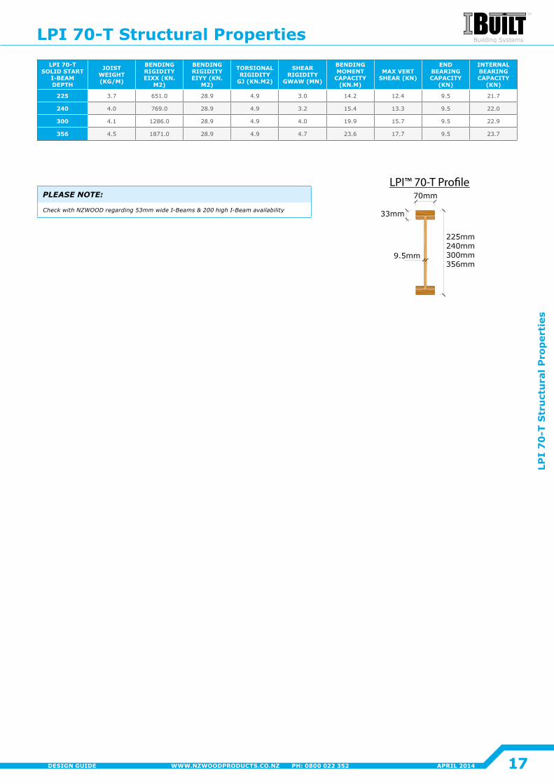
LPI™ 70-T Pro�le
LPI 70-T SOLID START
I-BEAM DEPTH
JOIST WEIGHT (KG/M)
BENDING RIGIDITY EIXX (KN.
M2)
BENDING RIGIDITY EIYY (KN.
M2)
TORSIONAL RIGIDITY
GJ (KN.M2)
SHEAR RIGIDITY
GWAW (MN)
BENDING MOMENT
CAPACITY (KN.M)
MAX VERT SHEAR (KN)
END BEARING CAPACITY
(KN)
INTERNAL BEARING CAPACITY
(KN)
225 3.7 651.0 28.9 4.9 3.0 14�2 12�4 9.5 21.7
240 4�0 769.0 28.9 4.9 3.2 15.4 13.3 9.5 22�0
300 4�1 1286.0 28.9 4.9 4�0 19.9 15.7 9.5 22.9
356 4.5 1871.0 28.9 4.9 4.7 23.6 17.7 9.5 23.7
LPI 70-T Structural Properties
17
LPI
70
-T S
tru
ctu
ral P
rop
erti
es
APRIL 2014WWW.NZWOODPRODUCTS.CO.NZ PH: 0800 022 352DESIGN GUIDE
PLEASE NOTE:
Check with NZWOOD regarding 53mm wide I-Beams & 200 high I-Beam availability
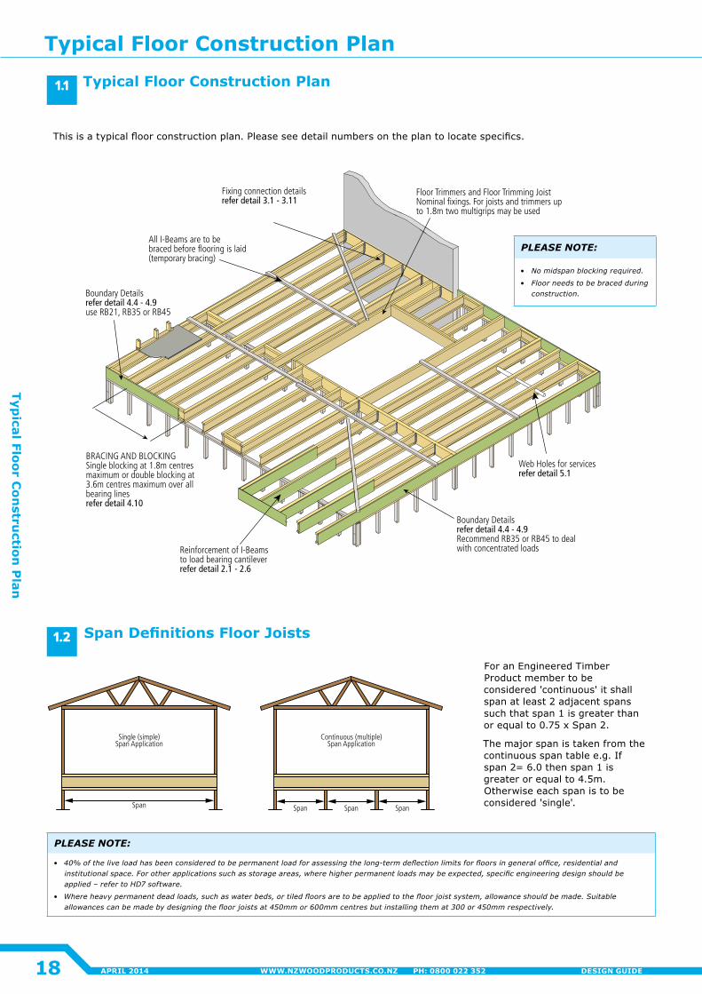
Reinforcement of I-Beams to load bearing cantileverrefer detail 2.1 - 2.6
Boundary Details refer detail 4.4 - 4.9Recommend RB35 or RB45 to deal with concentrated loads
Boundary Details refer detail 4.4 - 4.9use RB21, RB35 or RB45
BRACING AND BLOCKING Single blocking at 1.8m centres maximum or double blocking at 3.6m centres maximum over all bearing linesrefer detail 4.10
Fixing connection details refer detail 3.1 - 3.11
Web Holes for services refer detail 5.1
Floor Trimmers and Floor Trimming JoistNominal fixings. For joists and trimmers upto 1.8m two multigrips may be used
All I-Beams are to be braced before flooring is laid (temporary bracing)
Span
Single (simple)Span Application
SpanSpan Span
Continuous (multiple)Span Application
This is a typical floor construction plan. Please see detail numbers on the plan to locate specifics.
Typical Floor Construction Plan
Span Definitions Floor Joists
PLEASE NOTE:
• No midspan blocking required.
• Floor needs to be braced during construction.
For an Engineered Timber Product member to be considered 'continuous' it shall span at least 2 adjacent spans such that span 1 is greater than or equal to 0.75 x Span 2.
The major span is taken from the continuous span table e.g. If span 2= 6.0 then span 1 is greater or equal to 4.5m. Otherwise each span is to be considered 'single'.
PLEASE NOTE:
• 40%oftheliveloadhasbeenconsideredtobepermanentloadforassessingthelong-termdeflectionlimitsforfloorsingeneraloffice,residentialandinstitutionalspace.Forotherapplicationssuchasstorageareas,wherehigherpermanentloadsmaybeexpected,specificengineeringdesignshouldbeapplied – refer to HD7 software.
• Whereheavypermanentdeadloads,suchaswaterbeds,ortiledfloorsaretobeappliedtothefloorjoistsystem,allowanceshouldbemade.Suitableallowancescanbemadebydesigningthefloorjoistsat450mmor600mmcentresbutinstallingthemat300or450mmrespectively.
1.1
1.2
Typical Floor Construction Plan
18
Typical Floor C
onstru
ction P
lan
APRIL 2014 WWW.NZWOODPRODUCTS.CO.NZ PH: 0800 022 352 DESIGN GUIDE
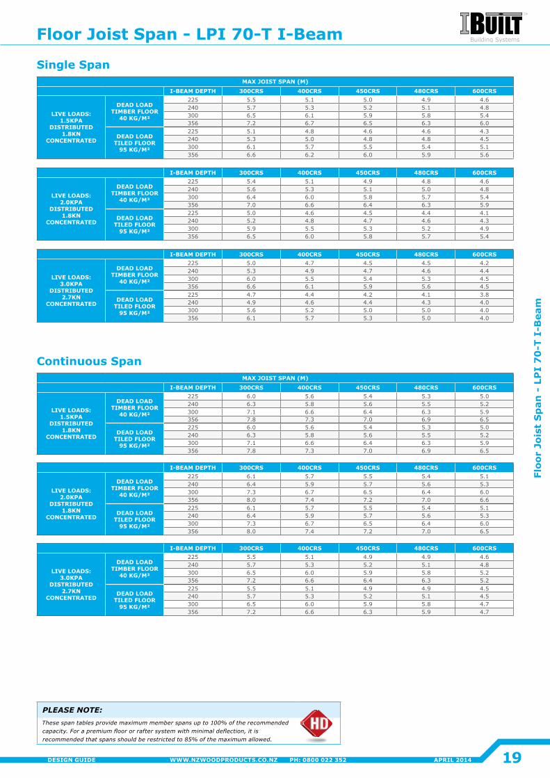
MAX JOIST SPAN (M)I-BEAM DEPTH 300CRS 400CRS 450CRS 480CRS 600CRS
LIVE LOADS: 1.5KPA
DISTRIBUTED 1.8KN
CONCENTRATED
DEAD LOAD TIMBER FLOOR
40 KG/M²
225 5.5 5.1 5.0 4.9 4.6240 5.7 5.3 5.2 5.1 4.8300 6.5 6.1 5.9 5.8 5.4356 7.2 6.7 6.5 6.3 6.0
DEAD LOAD TILED FLOOR
95 KG/M²
225 5.1 4.8 4.6 4.6 4.3240 5.3 5.0 4.8 4.8 4.5300 6.1 5.7 5.5 5.4 5.1356 6.6 6.2 6.0 5.9 5.6
I-BEAM DEPTH 300CRS 400CRS 450CRS 480CRS 600CRS
LIVE LOADS: 2.0KPA
DISTRIBUTED 1.8KN
CONCENTRATED
DEAD LOAD TIMBER FLOOR
40 KG/M²
225 5.4 5.1 4.9 4.8 4.6240 5.6 5.3 5.1 5.0 4.8300 6.4 6.0 5.8 5.7 5.4356 7.0 6.6 6.4 6.3 5.9
DEAD LOAD TILED FLOOR
95 KG/M²
225 5.0 4.6 4.5 4�4 4�1240 5.2 4.8 4.7 4.6 4.3300 5.9 5.5 5.3 5.2 4.9356 6.5 6.0 5.8 5.7 5.4
I-BEAM DEPTH 300CRS 400CRS 450CRS 480CRS 600CRS
LIVE LOADS: 3.0KPA
DISTRIBUTED 2.7KN
CONCENTRATED
DEAD LOAD TIMBER FLOOR
40 KG/M²
225 5.0 4.7 4.5 4.5 4�2240 5.3 4.9 4.7 4.6 4�4300 6.0 5.5 5.4 5.3 4.5356 6.6 6.1 5.9 5.6 4.5
DEAD LOAD TILED FLOOR
95 KG/M²
225 4.7 4�4 4�2 4�1 3.8240 4.9 4.6 4�4 4.3 4�0300 5.6 5.2 5.0 5.0 4�0356 6.1 5.7 5.3 5.0 4�0
MAX JOIST SPAN (M)I-BEAM DEPTH 300CRS 400CRS 450CRS 480CRS 600CRS
LIVE LOADS: 1.5KPA
DISTRIBUTED 1.8KN
CONCENTRATED
DEAD LOAD TIMBER FLOOR
40 KG/M²
225 6.0 5.6 5.4 5.3 5.0240 6.3 5.8 5.6 5.5 5.2300 7.1 6.6 6.4 6.3 5.9356 7.8 7.3 7.0 6.9 6.5
DEAD LOAD TILED FLOOR
95 KG/M²
225 6.0 5.6 5.4 5.3 5.0240 6.3 5.8 5.6 5.5 5.2300 7.1 6.6 6.4 6.3 5.9356 7.8 7.3 7.0 6.9 6.5
I-BEAM DEPTH 300CRS 400CRS 450CRS 480CRS 600CRS
LIVE LOADS: 2.0KPA
DISTRIBUTED 1.8KN
CONCENTRATED
DEAD LOAD TIMBER FLOOR
40 KG/M²
225 6.1 5.7 5.5 5.4 5.1240 6.4 5.9 5.7 5.6 5.3300 7.3 6.7 6.5 6.4 6.0356 8.0 7.4 7.2 7.0 6.6
DEAD LOAD TILED FLOOR
95 KG/M²
225 6.1 5.7 5.5 5.4 5.1240 6.4 5.9 5.7 5.6 5.3300 7.3 6.7 6.5 6.4 6.0356 8.0 7.4 7.2 7.0 6.5
I-BEAM DEPTH 300CRS 400CRS 450CRS 480CRS 600CRS
LIVE LOADS: 3.0KPA
DISTRIBUTED 2.7KN
CONCENTRATED
DEAD LOAD TIMBER FLOOR
40 KG/M²
225 5.5 5.1 4.9 4.9 4.6240 5.7 5.3 5.2 5.1 4.8300 6.5 6.0 5.9 5.8 5.2356 7.2 6.6 6.4 6.3 5.2
DEAD LOAD TILED FLOOR
95 KG/M²
225 5.5 5.1 4.9 4.9 4.5240 5.7 5.3 5.2 5.1 4.5300 6.5 6.0 5.9 5.8 4.7356 7.2 6.6 6.3 5.9 4.7
PLEASE NOTE:These span tables provide maximum member spans up to 100% of the recommended capacity. For a premium floor or rafter system with minimal deflection, it is recommended that spans should be restricted to 85% of the maximum allowed.
Continuous Span
Single Span
Floor Joist Span - LPI 70-T I-Beam
19
Floo
r Jo
ist
Sp
an -
LP
I 7
0-T
I-B
eam
APRIL 2014WWW.NZWOODPRODUCTS.CO.NZ PH: 0800 022 352DESIGN GUIDE
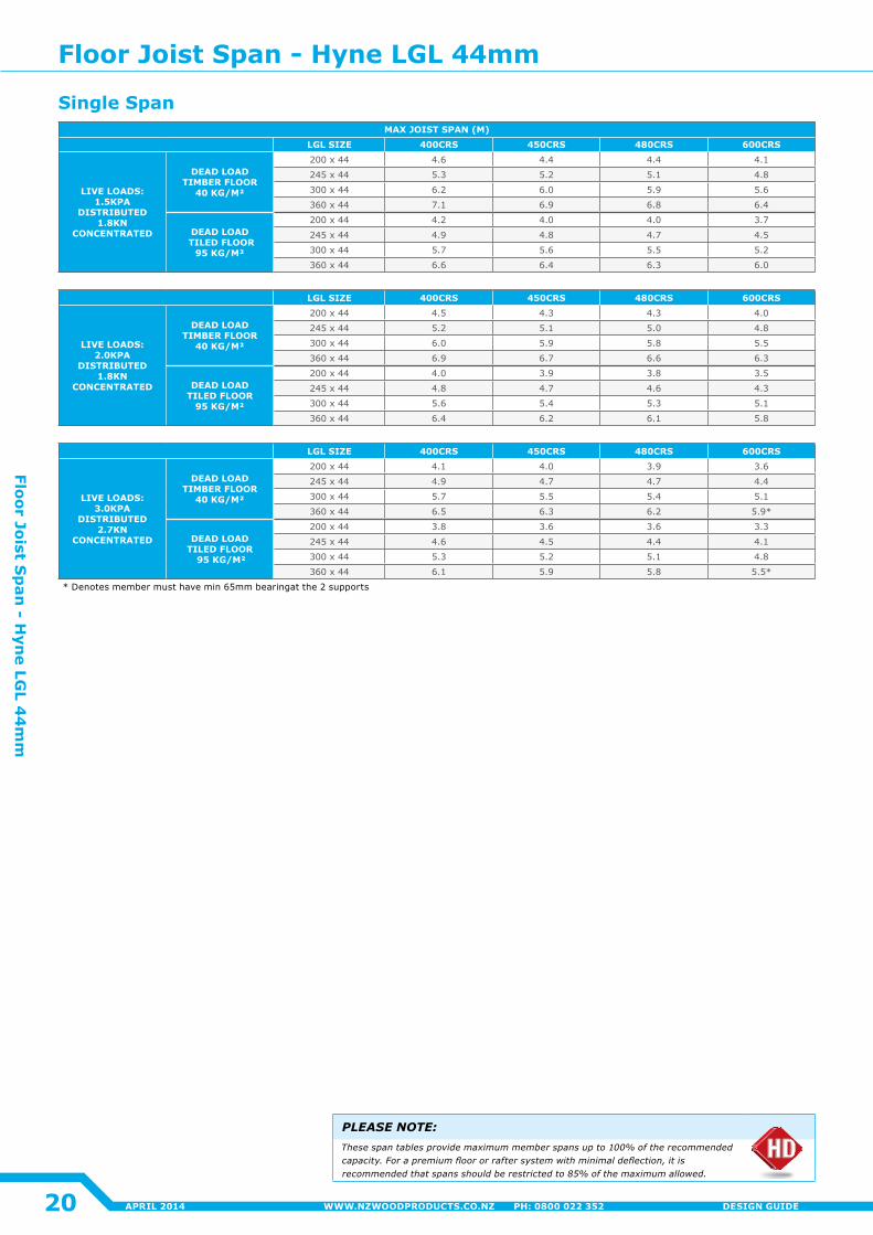
MAX JOIST SPAN (M)LGL SIZE 400CRS 450CRS 480CRS 600CRS
LIVE LOADS: 1.5KPA
DISTRIBUTED 1.8KN
CONCENTRATED
DEAD LOAD TIMBER FLOOR
40 KG/M²
200 x 44 4.6 4�4 4�4 4�1
245 x 44 5.3 5.2 5.1 4.8
300 x 44 6.2 6.0 5.9 5.6
360 x 44 7.1 6.9 6.8 6.4
DEAD LOAD TILED FLOOR
95 KG/M²
200 x 44 4�2 4�0 4�0 3.7
245 x 44 4.9 4.8 4.7 4.5
300 x 44 5.7 5.6 5.5 5.2
360 x 44 6.6 6.4 6.3 6.0
LGL SIZE 400CRS 450CRS 480CRS 600CRS
LIVE LOADS: 2.0KPA
DISTRIBUTED 1.8KN
CONCENTRATED
DEAD LOAD TIMBER FLOOR
40 KG/M²
200 x 44 4.5 4.3 4.3 4�0
245 x 44 5.2 5.1 5.0 4.8
300 x 44 6.0 5.9 5.8 5.5
360 x 44 6.9 6.7 6.6 6.3
DEAD LOAD TILED FLOOR
95 KG/M²
200 x 44 4�0 3.9 3.8 3.5
245 x 44 4.8 4.7 4.6 4.3
300 x 44 5.6 5.4 5.3 5.1
360 x 44 6.4 6.2 6.1 5.8
LGL SIZE 400CRS 450CRS 480CRS 600CRS
LIVE LOADS: 3.0KPA
DISTRIBUTED 2.7KN
CONCENTRATED
DEAD LOADTIMBER FLOOR
40 KG/M²
200 x 44 4�1 4�0 3.9 3.6
245 x 44 4.9 4.7 4.7 4�4
300 x 44 5.7 5.5 5.4 5.1
360 x 44 6.5 6.3 6.2 5.9*
DEAD LOADTILED FLOOR
95 KG/M²
200 x 44 3.8 3.6 3.6 3.3
245 x 44 4.6 4.5 4�4 4�1
300 x 44 5.3 5.2 5.1 4.8
360 x 44 6.1 5.9 5.8 5.5*
* Denotes member must have min 65mm bearingat the 2 supports
PLEASE NOTE:These span tables provide maximum member spans up to 100% of the recommended capacity. For a premium floor or rafter system with minimal deflection, it is recommended that spans should be restricted to 85% of the maximum allowed.
Single Span
Floor Joist Span - Hyne LGL 44mm
20
Floor Joist Sp
an - H
yne LG
L 44
mm
APRIL 2014 WWW.NZWOODPRODUCTS.CO.NZ PH: 0800 022 352 DESIGN GUIDE
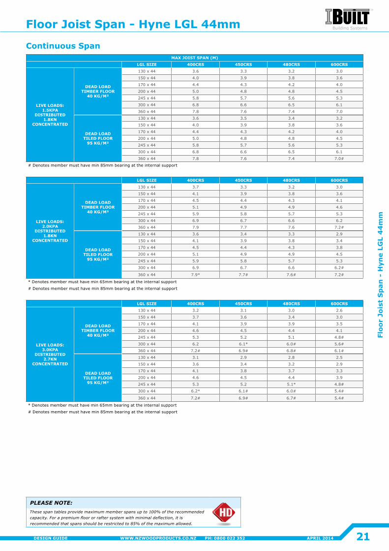
MAX JOIST SPAN (M)LGL SIZE 400CRS 450CRS 480CRS 600CRS
LIVE LOADS: 1.5KPA
DISTRIBUTED 1.8KN
CONCENTRATED
DEAD LOAD TIMBER FLOOR
40 KG/M²
130 x 44 3.6 3.3 3.2 3.0
150 x 44 4�0 3.9 3.8 3.6
170 x 44 4�4 4.3 4�2 4�0
200 x 44 5.0 4.8 4.8 4.5
245 x 44 5.8 5.7 5.6 5.3
300 x 44 6.8 6.6 6.5 6.1
360 x 44 7.8 7.6 7.4 7.0
DEAD LOAD TILED FLOOR
95 KG/M²
130 x 44 3.6 3.5 3.4 3.2
150 x 44 4�0 3.9 3.8 3.6
170 x 44 4�4 4.3 4�2 4�0
200 x 44 5.0 4.8 4.8 4.5
245 x 44 5.8 5.7 5.6 5.3
300 x 44 6.8 6.6 6.5 6.1
360 x 44 7.8 7.6 7.4 7.0#
# Denotes member must have min 85mm bearing at the internal support
LGL SIZE 400CRS 450CRS 480CRS 600CRS
LIVE LOADS: 2.0KPA
DISTRIBUTED 1.8KN
CONCENTRATED
DEAD LOAD TIMBER FLOOR
40 KG/M²
130 x 44 3.7 3.3 3.2 3.0
150 x 44 4�1 3.9 3.8 3.6
170 x 44 4.5 4�4 4.3 4�1
200 x 44 5.1 4.9 4.9 4.6
245 x 44 5.9 5.8 5.7 5.3
300 x 44 6.9 6.7 6.6 6.2
360 x 44 7.9 7.7 7.6 7.2#
DEAD LOAD TILED FLOOR
95 KG/M²
130 x 44 3.6 3.4 3.3 2.9
150 x 44 4�1 3.9 3.8 3.4
170 x 44 4.5 4�4 4.3 3.8
200 x 44 5.1 4.9 4.9 4.5
245 x 44 5.9 5.8 5.7 5.3
300 x 44 6.9 6.7 6.6 6.2#
360 x 44 7.9* 7.7# 7.6# 7.2#
* Denotes member must have min 65mm bearing at the internal support
# Denotes member must have min 85mm bearing at the internal support
LGL SIZE 400CRS 450CRS 480CRS 600CRS
LIVE LOADS: 3.0KPA
DISTRIBUTED 2.7KN
CONCENTRATED
DEAD LOAD TIMBER FLOOR
40 KG/M²
130 x 44 3.2 3.1 3.0 2.6
150 x 44 3.7 3.6 3.4 3.0
170 x 44 4�1 3.9 3.9 3.5
200 x 44 4.6 4.5 4�4 4�1
245 x 44 5.3 5.2 5.1 4.8#
300 x 44 6.2 6.1* 6.0# 5.6#
360 x 44 7.2# 6.9# 6.8# 6.1#
DEAD LOAD TILED FLOOR
95 KG/M²
130 x 44 3.1 2.9 2.8 2.5
150 x 44 3.6 3.4 3.2 2.9
170 x 44 4�1 3.8 3.7 3.3
200 x 44 4.6 4.5 4�4 3.9
245 x 44 5.3 5.2 5.1* 4.8#
300 x 44 6.2* 6.1# 6.0# 5.4#
360 x 44 7.2# 6.9# 6.7# 5.4#
* Denotes member must have min 65mm bearing at the internal support
# Denotes member must have min 85mm bearing at the internal support
PLEASE NOTE:These span tables provide maximum member spans up to 100% of the recommended capacity. For a premium floor or rafter system with minimal deflection, it is recommended that spans should be restricted to 85% of the maximum allowed.
Continuous Span
Floor Joist Span - Hyne LGL 44mm
21
Floo
r Jo
ist
Sp
an -
Hyn
e LG
L 4
4m
m
APRIL 2014WWW.NZWOODPRODUCTS.CO.NZ PH: 0800 022 352DESIGN GUIDE
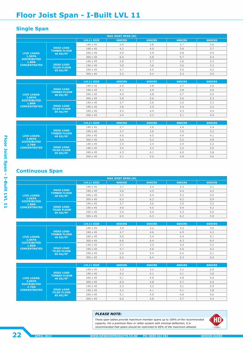
MAX JOIST SPAN (M)LVL11 SIZE 400CRS 450CRS 480CRS 600CRS
LIVE LOADS: 1.5KPA
DISTRIBUTED 1.8KN
CONCENTRATED
DEAD LOAD TIMBER FLOOR
40 KG/M²
140 x 45 2.9 2.8 2.7 2.6
190 x 45 4�2 4�0 3.9 3.7
240 x 45 5.0 4.9 4.8 4.5
300 x 45 6.0 5.8 5.7 5.4
DEAD LOAD TILED FLOOR
95 KG/M²
140 x 45 2.8 2.7 2.6 2�4
190 x 45 3.8 3.6 3.6 3.3
240 x 45 4.7 4.5 4.5 4�2
300 x 45 5.5 5.4 5.3 5.0
MAX JOIST SPAN (M)LVL11 SIZE 400CRS 450CRS 480CRS 600CRS
LIVE LOADS: 1.5KPA
DISTRIBUTED 1.8KN
CONCENTRATED
DEAD LOAD TIMBER FLOOR
40 KG/M²
140 x 45 3.7 3.4 3.3 3.1
190 x 45 4.6 4.5 4�4 4�2
240 x 45 5.5 5.4 5.3 5.0
300 x 45 6.5 6.3 6.2 5.9
DEAD LOAD TILED FLOOR
95 KG/M²
140 x 45 3.7 3.6 3.5 3.2
190 x 45 4.6 4.5 4�4 4�2
240 x 45 5.5 5.4 5.3 5.0
300 x 45 6.5 6.3 6.2 5.9
LVL11 SIZE 400CRS 450CRS 480CRS 600CRS
LIVE LOADS: 2.0KPA
DISTRIBUTED 1.8KN
CONCENTRATED
DEAD LOAD TIMBER FLOOR
40 KG/M²
140 x 45 2.9 2.8 2.7 2.6
190 x 45 4�1 3.9 3.8 3.6
240 x 45 4.9 4.8 4.7 4.5
300 x 45 5.8 5.6 5.6 5.3
DEAD LOAD TILED FLOOR
95 KG/M²
140 x 45 2.7 2.6 2.5 2.3
190 x 45 3.6 3.5 3.4 3.2
240 x 45 4.5 4�4 4.3 4�0
300 x 45 5.4 5.2 5.1 4.9
LVL11 SIZE 400CRS 450CRS 480CRS 600CRS
LIVE LOADS: 2.0KPA
DISTRIBUTED 1.8KN
CONCENTRATED
DEAD LOAD TIMBER FLOOR
40 KG/M²
140 x 45 3.5 3.2 3.2 3.0
190 x 45 4.7 4.6 4.5 4�2
240 x 45 5.6 5.4 5.4 5.1
300 x 45 6.6 6.4 6.3 6.0
DEAD LOAD TILED FLOOR
95 KG/M²
140 x 45 3.7 3.5 3.4 3.2
190 x 45 4.7 4.6 4.5 4�2
240 x 45 5.6 5.4 5.4 5.1
300 x 45 6.6 6.4 6.3 6.0
LVL11 SIZE 400CRS 450CRS 480CRS 600CRS
LIVE LOADS: 3.0KPA
DISTRIBUTED 2.7KN
CONCENTRATED
DEAD LOAD TIMBER FLOOR
40 KG/M²
140 x 45 2.7 2.6 2.6 2�4
190 x 45 3.7 3.6 3.5 3.3
240 x 45 4.6 4.5 4�4 4�1
300 x 45 5.4 5.3 5.2 4.9
DEAD LOAD TILED FLOOR
95 KG/M²
140 x 45 2.5 2�4 2�4 2�2
190 x 45 3.4 3.3 3.2 3.0
240 x 45 4.3 4�1 4�0 3.8
300 x 45 5.1 5.0 4.9 4.6
LVL11 SIZE 400CRS 450CRS 480CRS 600CRS
LIVE LOADS: 3.0KPA
DISTRIBUTED 2.7KN
CONCENTRATED
DEAD LOAD TIMBER FLOOR
40 KG/M²
140 x 45 3.3 3.2 3.1 2.9
190 x 45 4�2 4�1 4�1 3.8
240 x 45 5.1 4.9 4.8 4.6
300 x 45 6.0 5.8 5.7 5.4
DEAD LOAD TILED FLOOR
95 KG/M²
140 x 45 3.3 3.2 3.1 2.9
190 x 45 4�2 4�1 4�1 3.8
240 x 45 5.1 4.9 4.8 4.6
300 x 45 6.0 5.8 5.7 5.4
PLEASE NOTE:These span tables provide maximum member spans up to 100% of the recommended capacity. For a premium floor or rafter system with minimal deflection, it is recommended that spans should be restricted to 85% of the maximum allowed.
Continuous Span
Single Span
Floor Joist Span - I-Built LVL 11
22
Floor Joist Sp
an - I-B
uilt LV
L 11
APRIL 2014 WWW.NZWOODPRODUCTS.CO.NZ PH: 0800 022 352 DESIGN GUIDE
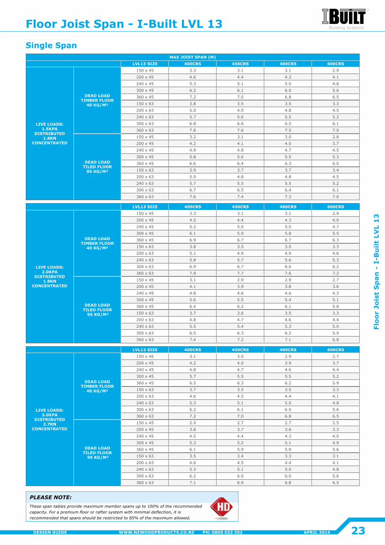
MAX JOIST SPAN (M)LVL13 SIZE 400CRS 450CRS 480CRS 600CRS
LIVE LOADS: 1.5KPA
DISTRIBUTED 1.8KN
CONCENTRATED
DEAD LOAD TIMBER FLOOR
40 KG/M²
150 x 45 3.3 3.1 3.1 2.9
200 x 45 4.6 4�4 4.3 4�1
240 x 45 5.3 5.1 5.0 4.8
300 x 45 6.2 6.1 6.0 5.6
360 x 45 7.2 7.0 6.8 6.5
150 x 63 3.8 3.5 3.5 3.3
200 x 63 5.0 4.9 4.8 4.5
240 x 63 5.7 5.6 5.5 5.2
300 x 63 6.8 6.6 6.5 6.1
360 x 63 7.8 7.6 7.5 7.0
DEAD LOAD TILED FLOOR
95 KG/M²
150 x 45 3.2 3.1 3.0 2.8
200 x 45 4�2 4�1 4�0 3.7
240 x 45 4.9 4.8 4.7 4.5
300 x 45 5.8 5.6 5.5 5.3
360 x 45 6.6 6.4 6.3 6.0
150 x 63 3.9 3.7 3.7 3.4
200 x 63 5.0 4.8 4.8 4.5
240 x 63 5.7 5.5 5.5 5.2
300 x 63 6.7 6.5 6.4 6.1
360 x 63 7.6 7.4 7.3 7.0
LVL13 SIZE 400CRS 450CRS 480CRS 600CRS
LIVE LOADS: 2.0KPA
DISTRIBUTED 1.8KN
CONCENTRATED
DEAD LOAD TIMBER FLOOR
40 KG/M²
150 x 45 3.3 3.1 3.1 2.9
200 x 45 4.5 4�4 4.3 4�0
240 x 45 5.2 5.0 5.0 4.7
300 x 45 6.1 5.9 5.8 5.5
360 x 45 6.9 6.7 6.7 6.3
150 x 63 3.8 3.5 3.5 3.3
200 x 63 5.1 4.9 4.9 4.6
240 x 63 5.8 5.7 5.6 5.3
300 x 63 6.9 6.7 6.6 6.2
360 x 63 7.9 7.7 7.6 7.2
DEAD LOAD TILED FLOOR
95 KG/M²
150 x 45 3.1 2.9 2.9 2.7
200 x 45 4�1 3.9 3.8 3.6
240 x 45 4.8 4.6 4.6 4.3
300 x 45 5.6 5.5 5.4 5.1
360 x 45 6.4 6.2 6.1 5.8
150 x 63 3.7 3.6 3.5 3.3
200 x 63 4.8 4.7 4.6 4�4
240 x 63 5.5 5.4 5.3 5.0
300 x 63 6.5 6.3 6.2 5.9
360 x 63 7.4 7.2 7.1 6.8
LVL13 SIZE 400CRS 450CRS 480CRS 600CRS
LIVE LOADS: 3.0KPA
DISTRIBUTED 2.7KN
CONCENTRATED
DEAD LOAD TIMBER FLOOR
40 KG/M²
150 x 45 3.1 3.0 2.9 2.7
200 x 45 4�2 4�0 3.9 3.7
240 x 45 4.8 4.7 4.6 4�4
300 x 45 5.7 5.5 5.5 5.2
360 x 45 6.5 6.3 6.2 5.9
150 x 63 3.7 3.5 3.5 3.3
200 x 63 4.6 4.5 4�4 4�1
240 x 63 5.3 5.1 5.0 4.8
300 x 63 6.2 6.1 6.0 5.6
360 x 63 7.2 7.0 6.8 6.5
DEAD LOAD TILED FLOOR
95 KG/M²
150 x 45 2.9 2.7 2.7 2.5
200 x 45 3.8 3.7 3.6 3.3
240 x 45 4.5 4�4 4.3 4�0
300 x 45 5.3 5.2 5.1 4.9
360 x 45 6.1 5.9 5.9 5.6
150 x 63 3.5 3.4 3.3 3.1
200 x 63 4.6 4.5 4�4 4�1
240 x 63 5.3 5.1 5.0 4.8
300 x 63 6.2 6.0 6.0 5.6
360 x 63 7.1 6.9 6.8 6.5
PLEASE NOTE:These span tables provide maximum member spans up to 100% of the recommended capacity. For a premium floor or rafter system with minimal deflection, it is recommended that spans should be restricted to 85% of the maximum allowed.
Single Span
Floor Joist Span - I-Built LVL 13
23
Floo
r Jo
ist
Sp
an -
I-B
uilt
LV
L 1
3
APRIL 2014WWW.NZWOODPRODUCTS.CO.NZ PH: 0800 022 352DESIGN GUIDE
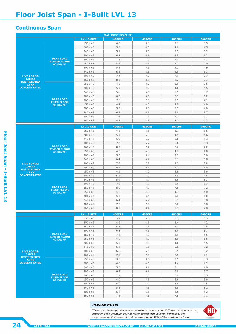
MAX JOIST SPAN (M)LVL13 SIZE 400CRS 450CRS 480CRS 600CRS
LIVE LOADS: 1.5KPA
DISTRIBUTED 1.8KN
CONCENTRATED
DEAD LOAD TIMBER FLOOR
40 KG/M²
150 x 45 4�0 3.8 3.7 3.5
200 x 45 5.0 4.9 4.8 4.5
240 x 45 5.8 5.6 5.5 5.2
300 x 45 6.8 6.6 6.5 6.2
360 x 45 7.8 7.6 7.5 7.1
150 x 63 4�4 4.3 4�2 4�0
200 x 63 5.5 5.3 5.2 4.9
240 x 63 6.3 6.1 6.0 5.7
300 x 63 7.4 7.2 7.1 6.7
360 x 63 8.5 8.3 8.2 7.7
DEAD LOAD TILED FLOOR
95 KG/M²
150 x 45 4�0 3.9 3.9 3.6
200 x 45 5.0 4.9 4.8 4.5
240 x 45 5.8 5.6 5.5 5.2
300 x 45 6.8 6.6 6.5 6.2
360 x 45 7.8 7.6 7.5 7.1
150 x 63 4�4 4.3 4�2 4�0
200 x 63 5.5 5.3 5.2 4.9
240 x 63 6.3 6.1 6.0 5.7
300 x 63 7.4 7.2 7.1 6.7
360 x 63 8.5 8.3 8.2 7.7
LVL13 SIZE 400CRS 450CRS 480CRS 600CRS
LIVE LOADS: 2.0KPA
DISTRIBUTED 1.8KN
CONCENTRATED
DEAD LOAD TIMBER FLOOR
40 KG/M²
150 x 45 4�1 3.8 3.7 3.5
200 x 45 5.1 5.0 4.9 4.6
240 x 45 5.9 5.7 5.6 5.3
300 x 45 7.0 6.7 6.6 6.3
360 x 45 8.0 7.7 7.6 7.2
150 x 63 4.5 4.3 4�2 4�0
200 x 63 5.6 5.4 5.3 5.0
240 x 63 6.4 6.2 6.1 5.8
300 x 63 7.6 7.3 7.2 6.8
360 x 63 8.7 8.4 8.3 7.8
DEAD LOAD TILED FLOOR
95 KG/M²
150 x 45 4�1 4�0 3.9 3.6
200 x 45 5.1 5.0 4.9 4.6
240 x 45 5.9 5.7 5.6 5.3
300 x 45 7.0 6.7 6.6 6.3
360 x 45 8.0 7.7 7.6 7.2
150 x 63 4.5 4.3 4.3 4�0
200 x 63 5.6 5.4 5.3 5.0
240 x 63 6.4 6.2 6.1 5.8
300 x 63 7.6 7.3 7.2 6.8
360 x 63 8.7 8.4 8.3 7.8
LVL13 SIZE 400CRS 450CRS 480CRS 600CRS
LIVE LOADS: 3.0KPA
DISTRIBUTED 2.7KN
CONCENTRATED
DEAD LOAD TIMBER FLOOR
40 KG/M²
150 x 45 3.7 3.6 3.5 3.3
200 x 45 4.6 4.5 4�4 4�2
240 x 45 5.3 5.1 5.1 4.8
300 x 45 6.3 6.1 6.0 5.7
360 x 45 7.2 7.0 6.9 6.5
150 x 63 4�0 3.9 3.9 3.6
200 x 63 5.0 4.9 4.8 4.5
240 x 63 5.8 5.6 5.5 5.2
300 x 63 6.8 6.6 6.5 6.2
360 x 63 7.8 7.6 7.5 7.1
DEAD LOAD TILED FLOOR
95 KG/M²
150 x 45 3.7 3.6 3.5 3.3
200 x 45 4.6 4.5 4�4 4�2
240 x 45 5.3 5.1 5.1 4.8
300 x 45 6.3 6.1 6.0 5.7
360 x 45 7.2 7.0 6.9 6.5
150 x 63 4�0 3.9 3.9 3.6
200 x 63 5.0 4.9 4.8 4.5
240 x 63 5.8 5.6 5.5 5.2
300 x 63 6.8 6.6 6.5 6.2
360 x 63 7.8 7.6 7.5 7.1
Floor Joist Span - I-Built LVL 13
PLEASE NOTE:These span tables provide maximum member spans up to 100% of the recommended capacity. For a premium floor or rafter system with minimal deflection, it is recommended that spans should be restricted to 85% of the maximum allowed.
Continuous Span
24
Floor Joist Sp
an - I-B
uilt LV
L 13
APRIL 2014 WWW.NZWOODPRODUCTS.CO.NZ PH: 0800 022 352 DESIGN GUIDE
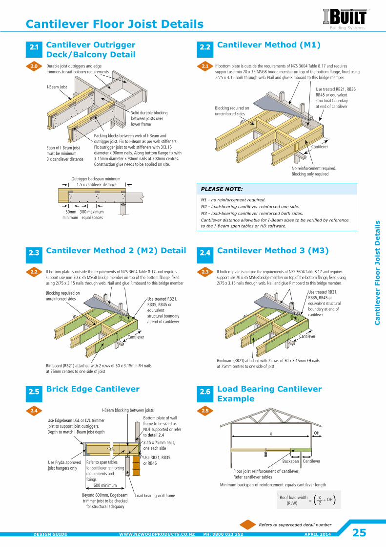
No reinforcement required. Blocking only required
Cantilever
If bottom plate is outside the requirements of NZS 3604 Table 8.17 and requires support use min 70 x 35 MSG8 bridge member on top of the bottom flange, fixed using 2/75 x 3.15 nails through web. Nail and glue Rimboard to this bridge member.
Blocking required onunreinforced sides
Use treated RB21, RB35RB45 or equivalent structural boundary at end of cantilever
Span of I-Beam joist must be minimum 3 x cantilever distance
Durable joist outriggers and edge trimmers to suit balcony requirements
I-Beam Joist
50mmminimum
300 maximum equal spaces
Outrigger backspan minimum 1.5 x cantilever distance
Packing blocks between web of I-Beam and outrigger joist. Fix to I-Beam as per web stiffeners. Fix outrigger joist to web stiffeners with 3/3.15 diameter x 90mm nails. Along bottom flange fix with 3.15mm diameter x 90mm nails at 300mm centres. Construction glue needs to be applied on site.
Solid durable blocking between joists over lower frame
Cantilever
If bottom plate is outside the requirements of NZS 3604 Table 8.17 and requires support use min 70 x 35 MSG8 bridge member on top of the bottom flange, fixed using 2/75 x 3.15 nails through web. Nail and glue Rimboard to this bridge member
Use treated RB21, RB35, RB45 or equivalentstructural boundaryat end of cantilever
Rimboard (RB21) attached with 2 rows of 30 x 3.15mm FH nails at 75mm centres to one side of joist
Blocking required on unreinforced sides
Rimboard (RB21) attached with 2 rows of 30 x 3.15mm FH nails at 75mm centres to one side of joist
If bottom plate is outside the requirements of NZS 3604 Table 8.17 and requiressupport use 70 x 35 MSG8 bridge member on top of the bottom flange, fixed using 2/75 x 3.15 nails through web. Nail and glue Rimboard to this bridge member.
Cantilever
Use treated RB21, RB35, RB45 or equivalent structural boundary at end of cantilever
3.15 x 75mm nails, one each side
Use RB21, RB35 or RB45
Beyond 600mm, Edgebeam trimmer joist to be checked
for structural adequacy
Use Edgebeam LGL or LVL trimmer joist to support joist outriggers. Depth to match I-Beam joist depth
Refer to span tablesfor cantilever reinforcingrequirements and fixings
Use Pryda approved joist hangers only
Load bearing wall frame
Bottom plate of wall frame to be sized as NOT supported or refer to detail 2.4
600 minimum
I-Beam blocking between joists
Floor joist reinforcement of cantilever,Refer cantilever tables
Minimum backspan of reinforcement equals cantilever length
Backspan Cantilever
OHX
Roof load width (RLW)
X2
OH= +
Refers to superceded detail number
PLEASE NOTE:
M1 - no reinforcement required.
M2 - load-bearing cantilever reinforced one side.
M3 - load-bearing cantilever reinforced both sides.
CantileverdistanceallowableforI-Beamsizestobeverifiedbyreferenceto the I-Beam span tables or HD software.
Cantilever Method (M1)
Cantilever Method 2 (M2) Detail
Cantilever Outrigger Deck/Balcony Detail
Brick Edge Cantilever Load Bearing Cantilever Example
Cantilever Method 3 (M3)
2.1 2.2
2.3 2.4
2.5 2.6
2.0
2.2
2.4
2.1
2.3
2.5
Cantilever Floor Joist Details
25
Can
tile
ver
Floo
r Jo
ist
Det
ails
APRIL 2014WWW.NZWOODPRODUCTS.CO.NZ PH: 0800 022 352DESIGN GUIDE
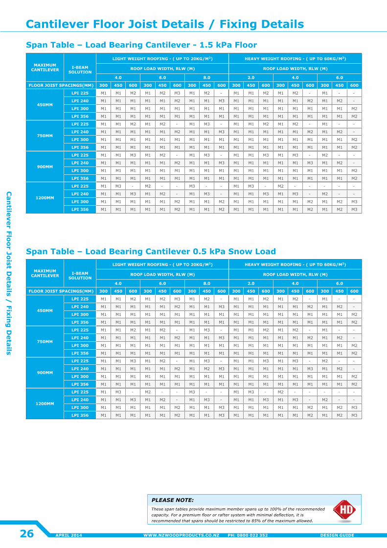
MAXIMUM CANTILEVER
I-BEAM
SOLUTION
LIGHT WEIGHT ROOFING - ( UP TO 20KG/M2) HEAVY WEIGHT ROOFING - ( UP TO 60KG/M2)
ROOF LOAD WIDTH, RLW (M) ROOF LOAD WIDTH, RLW (M)
4.0 6.0 8.0 2.0 4.0 6.0
FLOOR JOIST SPACINGS(MM) 300 450 600 300 450 600 300 450 600 300 450 600 300 450 600 300 450 600
450MM
LPI 225 M1 M1 M2 M1 M2 M3 M1 M2 - M1 M1 M2 M1 M2 - M1 - -
LPI 240 M1 M1 M1 M1 M1 M2 M1 M1 M3 M1 M1 M1 M1 M1 M2 M1 M2 -
LPI 300 M1 M1 M1 M1 M1 M1 M1 M1 M1 M1 M1 M1 M1 M1 M1 M1 M1 M2
LPI 356 M1 M1 M1 M1 M1 M1 M1 M1 M1 M1 M1 M1 M1 M1 M1 M1 M1 M2
750MM
LPI 225 M1 M1 M2 M1 M2 - M1 M3 - M1 M1 M2 M1 M2 - M1 - -
LPI 240 M1 M1 M1 M1 M1 M2 M1 M1 M3 M1 M1 M1 M1 M1 M2 M1 M2 -
LPI 300 M1 M1 M1 M1 M1 M1 M1 M1 M1 M1 M1 M1 M1 M1 M1 M1 M1 M2
LPI 356 M1 M1 M1 M1 M1 M1 M1 M1 M1 M1 M1 M1 M1 M1 M1 M1 M1 M2
900MM
LPI 225 M1 M1 M3 M1 M2 - M1 M3 - M1 M1 M3 M1 M3 - M2 - -
LPI 240 M1 M1 M1 M1 M1 M2 M1 M1 M3 M1 M1 M1 M1 M1 M3 M1 M2 -
LPI 300 M1 M1 M1 M1 M1 M1 M1 M1 M1 M1 M1 M1 M1 M1 M1 M1 M1 M2
LPI 356 M1 M1 M1 M1 M1 M1 M1 M1 M1 M1 M1 M1 M1 M1 M1 M1 M1 M2
1200MM
LPI 225 M1 M3 - M2 - - M3 - - M1 M3 - M2 - - - - -
LPI 240 M1 M1 M3 M1 M2 - M1 M3 - M1 M1 M3 M1 M3 - M2 - -
LPI 300 M1 M1 M1 M1 M1 M2 M1 M1 M2 M1 M1 M1 M1 M1 M2 M1 M2 M3
LPI 356 M1 M1 M1 M1 M1 M2 M1 M1 M2 M1 M1 M1 M1 M1 M2 M1 M2 M3
MAXIMUM CANTILEVER
I-BEAM
SOLUTION
LIGHT WEIGHT ROOFING - ( UP TO 20KG/M2) HEAVY WEIGHT ROOFING - ( UP TO 60KG/M2)
ROOF LOAD WIDTH, RLW (M) ROOF LOAD WIDTH, RLW (M)
4.0 6.0 8.0 2.0 4.0 6.0
FLOOR JOIST SPACINGS(MM) 300 450 600 300 450 600 300 450 600 300 450 600 300 450 600 300 450 600
450MM
LPI 225 M1 M1 M2 M1 M2 M3 M1 M2 - M1 M1 M2 M1 M2 - M1 - -
LPI 240 M1 M1 M1 M1 M1 M2 M1 M1 M3 M1 M1 M1 M1 M1 M2 M1 M2 -
LPI 300 M1 M1 M1 M1 M1 M1 M1 M1 M1 M1 M1 M1 M1 M1 M1 M1 M1 M2
LPI 356 M1 M1 M1 M1 M1 M1 M1 M1 M1 M1 M1 M1 M1 M1 M1 M1 M1 M2
750MM
LPI 225 M1 M1 M2 M1 M2 - M1 M3 - M1 M1 M2 M1 M2 - M1 - -
LPI 240 M1 M1 M1 M1 M1 M2 M1 M1 M3 M1 M1 M1 M1 M1 M2 M1 M2 -
LPI 300 M1 M1 M1 M1 M1 M1 M1 M1 M1 M1 M1 M1 M1 M1 M1 M1 M1 M2
LPI 356 M1 M1 M1 M1 M1 M1 M1 M1 M1 M1 M1 M1 M1 M1 M1 M1 M1 M2
900MM
LPI 225 M1 M1 M3 M1 M2 - M1 M3 - M1 M1 M3 M1 M3 - M2 - -
LPI 240 M1 M1 M1 M1 M1 M2 M1 M2 M3 M1 M1 M1 M1 M1 M3 M1 M2 -
LPI 300 M1 M1 M1 M1 M1 M1 M1 M1 M1 M1 M1 M1 M1 M1 M1 M1 M1 M2
LPI 356 M1 M1 M1 M1 M1 M1 M1 M1 M1 M1 M1 M1 M1 M1 M1 M1 M1 M2
1200MM
LPI 225 M1 M3 - M2 - - M3 - - M1 M3 - M2 - - - - -
LPI 240 M1 M1 M3 M1 M2 - M1 M3 - M1 M1 M3 M1 M3 - M2 - -
LPI 300 M1 M1 M1 M1 M1 M2 M1 M1 M3 M1 M1 M1 M1 M1 M2 M1 M2 M3
LPI 356 M1 M1 M1 M1 M1 M2 M1 M1 M3 M1 M1 M1 M1 M1 M2 M1 M2 M3
PLEASE NOTE:These span tables provide maximum member spans up to 100% of the recommended capacity. For a premium floor or rafter system with minimal deflection, it is recommended that spans should be restricted to 85% of the maximum allowed.
Span Table – Load Bearing Cantilever - 1.5 kPa Floor
Span Table – Load Bearing Cantilever 0.5 kPa Snow Load
Cantilever Floor Joist Details / Fixing Details
26
Can
tilever Floor Joist Details /
Fixing
Details
APRIL 2014 WWW.NZWOODPRODUCTS.CO.NZ PH: 0800 022 352 DESIGN GUIDE
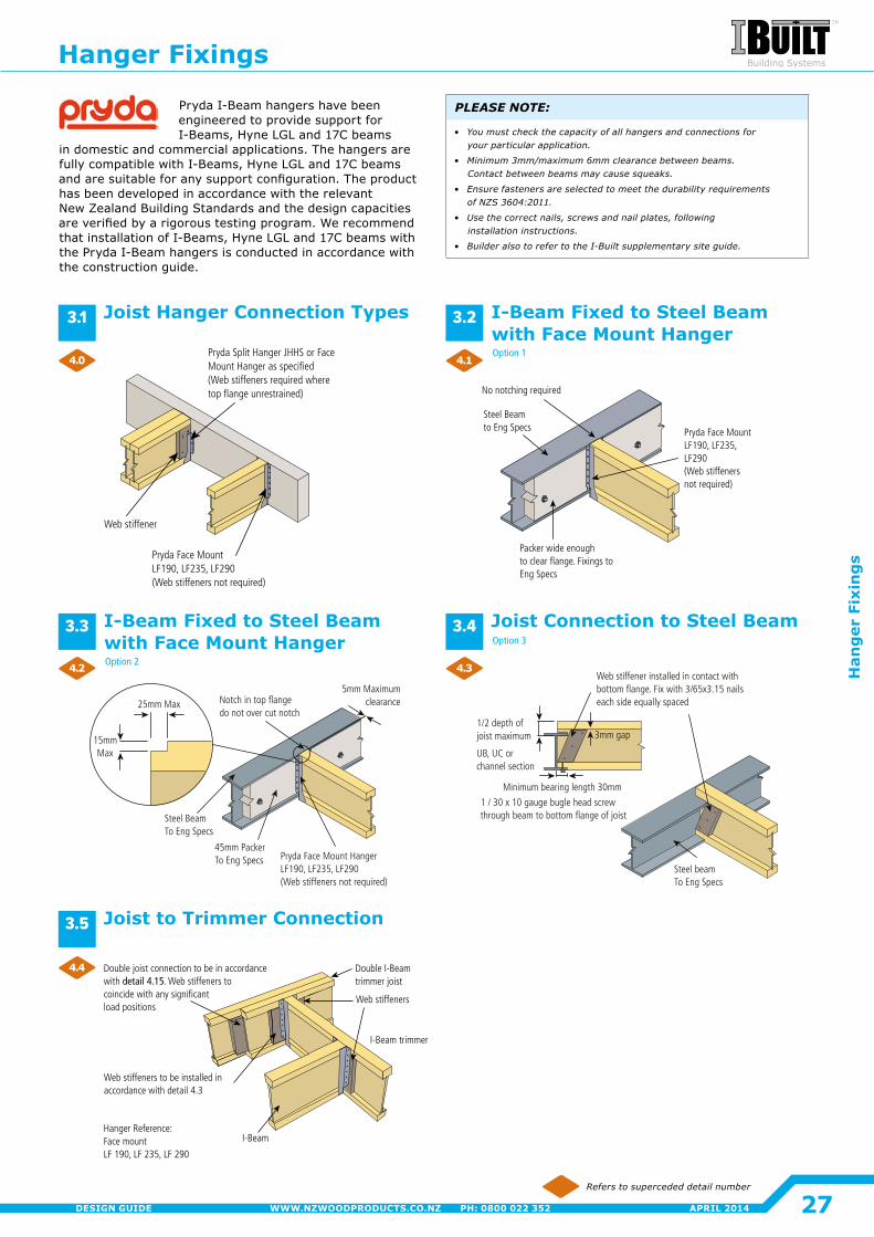
Web stiffener
Pryda Face MountLF190, LF235, LF290(Web stiffeners not required)
Pryda Split Hanger JHHS or Face Mount Hanger as specified (Web stiffeners required where top flange unrestrained)
45mm PackerTo Eng Specs
Steel BeamTo Eng Specs
Pryda Face Mount HangerLF190, LF235, LF290(Web stiffeners not required)
Notch in top flangedo not over cut notch
15mmMax
25mm Max
5mm Maximum clearance
Packer wide enoughto clear flange. Fixings to Eng Specs
Steel Beam to Eng Specs
No notching required
Pryda Face MountLF190, LF235, LF290(Web stiffenersnot required)
Double joist connection to be in accordancewith detail 4.15. Web stiffeners to coincide with any significant load positions
Web stiffeners
Web stiffeners to be installed in accordance with detail 4.3
Double I-Beam trimmer joist
I-Beam trimmer
I-BeamHanger Reference: Face mountLF 190, LF 235, LF 290
1 / 30 x 10 gauge bugle head screwthrough beam to bottom flange of joist
Steel beamTo Eng Specs
Minimum bearing length 30mm
UB, UC or channel section
Web stiffener installed in contact with bottom flange. Fix with 3/65x3.15 nails each side equally spaced
3mm gap1/2 depth of joist maximum
Refers to superceded detail number
Joist Connection to Steel Beam
Pryda I-Beam hangers have been engineered to provide support for I-Beams, Hyne LGL and 17C beams
in domestic and commercial applications. The hangers are fully compatible with I-Beams, Hyne LGL and 17C beams and are suitable for any support configuration. The product has been developed in accordance with the relevant New Zealand Building Standards and the design capacities are verified by a rigorous testing program. We recommend that installation of I-Beams, Hyne LGL and 17C beams with the Pryda I-Beam hangers is conducted in accordance with the construction guide�
Joist Hanger Connection Types
I-Beam Fixed to Steel Beam with Face Mount Hanger
I-Beam Fixed to Steel Beam with Face Mount HangerOption 1
Option 2
Option 3
Joist to Trimmer Connection
PLEASE NOTE:
• You must check the capacity of all hangers and connections for your particular application.
• Minimum3mm/maximum6mmclearancebetweenbeams. Contact between beams may cause squeaks.
• Ensure fasteners are selected to meet the durability requirements ofNZS3604:2011.
• Usethecorrectnails,screwsandnailplates,following installation instructions.
• Builder also to refer to the I-Built supplementary site guide.
3.1 3.2
3.3 3.4
3.5
4.0
4.2
4.4
4.1
4.3
Hanger Fixings
27
Han
ger
Fix
ing
s
APRIL 2014WWW.NZWOODPRODUCTS.CO.NZ PH: 0800 022 352DESIGN GUIDE
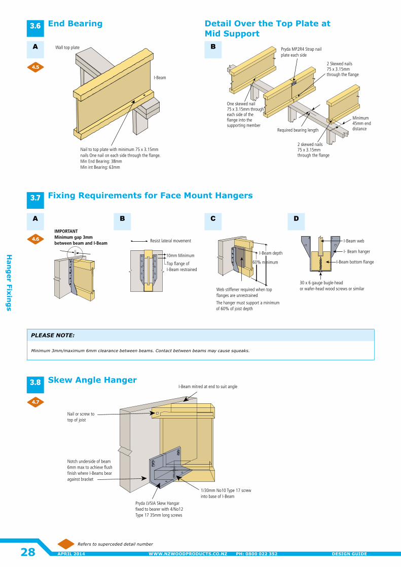
Pryda MP2R4 Strap nail plate each side
One skewed nail75 x 3.15mm through each side of the flange into the supporting member
Minimum 45mm end distance
2 skewed nails 75 x 3.15mmthrough the flange
Required bearing length
2 Skewed nails75 x 3.15mmthrough the flange
Nail to top plate with minimum 75 x 3.15mm nails One nail on each side through the flange.Min End Bearing: 38mmMin int Bearing: 63mm
Wall top plate
I-Beam
Notch underside of beam 6mm max to achieve flush finish where I-Beams bear against bracket
Nail or screw to top of joist
Pryda LVSIA Skew Hangar fixed to bearer with 4/No12 Type 17 35mm long screws
1/30mm No10 Type 17 screw into base of I-Beam
I-Beam mitred at end to suit angle
IMPORTANT Minimum gap 3mm between beam and I-Beam
I-Beam depth
60% minimum
The hanger must support a minimumof 60% of joist depth
Web stiffener required when top flanges are unrestrained
Resist lateral movement
10mm Minimum
Top flange of I-Beam restrained
I- Beam hanger
30 x 6 gauge bugle-head or wafer-head wood screws or similar
I-Beam bottom flange
I-Beam web
Refers to superceded detail number
Detail Over the Top Plate at Mid Support
A B
End Bearing
Skew Angle Hanger
A B C D
Fixing Requirements for Face Mount Hangers
PLEASE NOTE:
Minimum3mm/maximum6mmclearancebetweenbeams.Contactbetweenbeamsmaycausesqueaks.
3.6
3.8
3.7
4.5
4.6
4.7
28
Han
ger Fixin
gs
APRIL 2014 WWW.NZWOODPRODUCTS.CO.NZ PH: 0800 022 352 DESIGN GUIDE
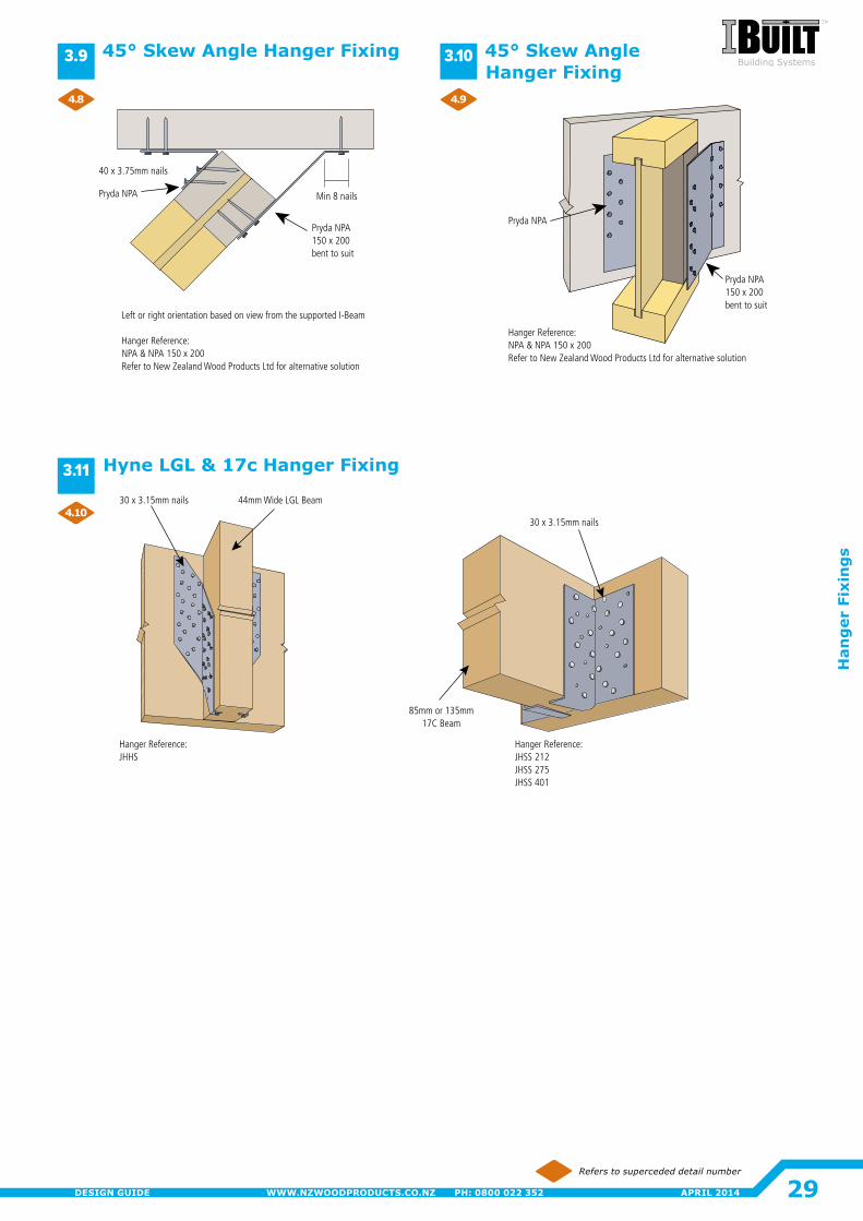
Hanger Reference: NPA & NPA 150 x 200Refer to New Zealand Wood Products Ltd for alternative solution
Pryda NPA
Pryda NPA150 x 200bent to suit
40 x 3.75mm nails
Pryda NPA
Pryda NPA 150 x 200 bent to suit
Min 8 nails
Left or right orientation based on view from the supported I-Beam
Hanger Reference: NPA & NPA 150 x 200Refer to New Zealand Wood Products Ltd for alternative solution
Hanger Reference:JHHS
30 x 3.15mm nails 44mm Wide LGL Beam
Hanger Reference: JHSS 212JHSS 275JHSS 401
30 x 3.15mm nails
85mm or 135mm17C Beam
Refers to superceded detail number
Hyne LGL & 17c Hanger Fixing
45° Skew Angle Hanger Fixing 45° Skew Angle Hanger Fixing
3.9 3.10
3.11
4.8
4.10
4.9
29
Han
ger
Fix
ing
s
APRIL 2014WWW.NZWOODPRODUCTS.CO.NZ PH: 0800 022 352DESIGN GUIDE
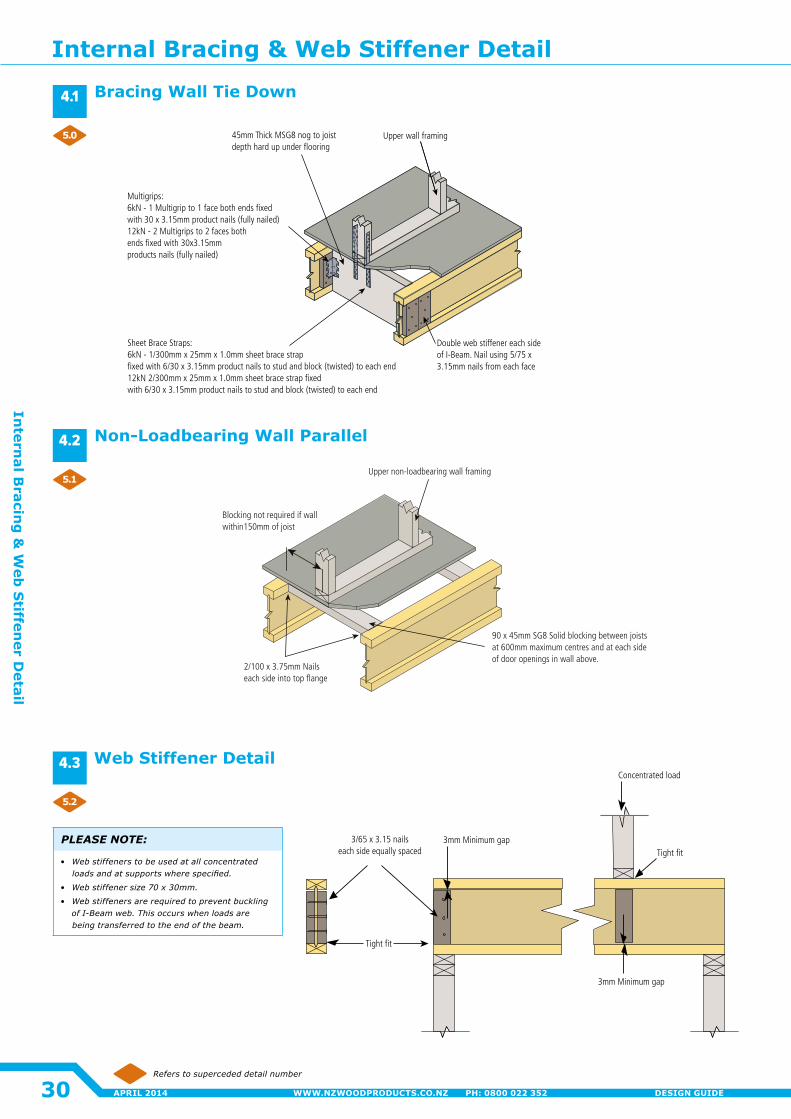
45mm Thick MSG8 nog to joist depth hard up under flooring
Sheet Brace Straps:6kN - 1/300mm x 25mm x 1.0mm sheet brace strap fixed with 6/30 x 3.15mm product nails to stud and block (twisted) to each end12kN 2/300mm x 25mm x 1.0mm sheet brace strap fixed with 6/30 x 3.15mm product nails to stud and block (twisted) to each end
Upper wall framing
Double web stiffener each side of I-Beam. Nail using 5/75 x 3.15mm nails from each face
Multigrips:6kN - 1 Multigrip to 1 face both ends fixedwith 30 x 3.15mm product nails (fully nailed)12kN - 2 Multigrips to 2 faces bothends fixed with 30x3.15mm products nails (fully nailed)
Tight fit
Concentrated load
3mm Minimum gap
3mm Minimum gap3/65 x 3.15 nails each side equally spaced
Tight fit
Upper non-loadbearing wall framing
90 x 45mm SG8 Solid blocking between joists at 600mm maximum centres and at each side of door openings in wall above.
Blocking not required if wall within150mm of joist
2/100 x 3.75mm Nails each side into top flange
Refers to superceded detail number
Bracing Wall Tie Down
Non-Loadbearing Wall Parallel
Web Stiffener Detail
PLEASE NOTE:
• Web stiffeners to be used at all concentrated loadsandatsupportswherespecified.
• Webstiffenersize70x30mm.
• Web stiffeners are required to prevent buckling of I-Beam web. This occurs when loads are being transferred to the end of the beam.
4.1
4.2
4.3
5.0
5.1
5.2
Internal Bracing & Web Stiffener Detail
30
Intern
al Bracin
g &
Web
Stiffen
er Detail
APRIL 2014 WWW.NZWOODPRODUCTS.CO.NZ PH: 0800 022 352 DESIGN GUIDE
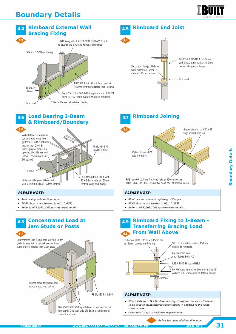
Fix RB35, RB45 H3.1 to I-Beam with 90 x 2.8mm nails at 150mm centres along each flangeFix bottom flange of I-Beam
with 75mm x 3.15mmnails at 150mm centres
Rimboard
Rimboard
BoundaryI-Beam
6kN and 12kN brace fixing
Web stiffeners behind strap bracing
12kN fixing with 2 SHEET BRACE STRAPS 6 nails to stud(s) and 6 nails to Rimboard per strap
Pryda 25 x 1.0 x 300 6kN fixing brace with 1 SHEET BRACE STRAP and 6 nails to stud and Rimboard
RB45 H3.1 with 90 x 2.8mm nails at 150mm centres staggered into I-Beams
Concentrated load from upper story eg. under girder trusses with a setback greater than 2.4m or lintel greater than 3.0m span
90 x 45 Radiata SG8 squash blocks 1mm deeper than joist depth. One each side of I-Beam or under point concentrated load
Squash block for joists under concentrated load points
RB21, RB35 or RB45
30mm
Fix bottom plate with 90 x 3.15mm nailsat 150mm centres into flooring
Fix Rimboard into each flange. Refer 4.7
RB35, RB45 Rimboard H3.1
Fix Rimboard into plates 30mm in and at 45° with 90 x 3.15mm nailed at 150mm centres
45°
90 x 3.15mm skew nails at 150mm centres to Rimboard
RB35, RB45 H3.1fixed to I-Beam
I-Beam
Girder truss
Fix Rimboard to I-Beam with 90 x 2.8mm nails at 150mmcentres along each flange
3.0m
Fix bottom flange of I-Beam with 75 x 3.15mm nails at 150mm centres
Web stiffeners used under concentrated loads from girder truss with a set back greater than 2.4m & Lintels greater than 3.0m opening. Fix siffeners with 3/65 x 3.15mm each side EQ. spaced.
I-Beam blocking or 2/90 x 45 Nogs at Rimboard join
Option to use RB21, RB35 or RB45
RB21 use 60 x 2.8mm flat head nails at 150mm centresRB35, RB45 use 90 x 3.15mm flat head nails at 150mm centres
Refers to superceded detail number
Rimboard End JoistRimboard External Wall Bracing Fixing
PLEASE NOTE:
• Avoid using wide section timber.
• AllRimboardsaretreatedtoH3.1(LOSP)
• RefertoNZS3602.2003fortreatmentdetails.
Load Bearing I-Beam & Rimboard/Boundary
PLEASE NOTE:
• Bluntnailendstoavoidsplittingofflanges.
• AllRimboardsaretreatedtoH3.1(LOSP)
• RefertoNZS3602.2003fortreatmentdetails.
Rimboard Joining
Concentrated Load at Jam Studs or Posts
PLEASE NOTE:
• Where6kNand12kNtiedownbracingstrapsarerequired-theseare tobefixedtomanufacturesspecificationsinadditiontothefixing shown above.
• OtherwallfixingstoNZS3604requirements.
Rimboard Fixing to I-Beam - Transferring Bracing Load From Wall Above
4.4
4.6
4.8
4.5
4.7
4.9
5.3
5.5
5.7
5.4
5.6
5.8
Boundary Details
31
Bou
nd
ary
Det
ails
APRIL 2014WWW.NZWOODPRODUCTS.CO.NZ PH: 0800 022 352DESIGN GUIDE
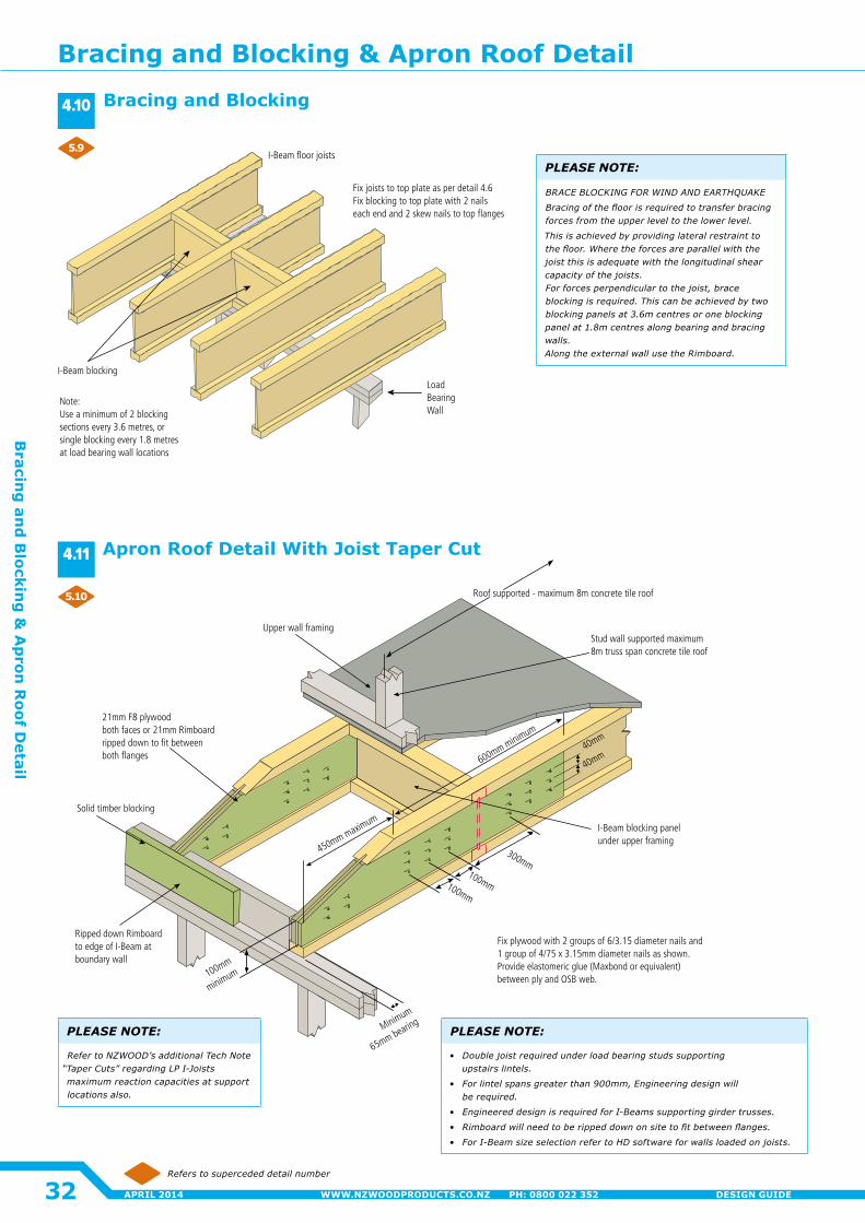
Note:Use a minimum of 2 blocking sections every 3.6 metres, or single blocking every 1.8 metres at load bearing wall locations
Load Bearing Wall
I-Beam floor joists
Fix joists to top plate as per detail 4.6Fix blocking to top plate with 2 nails each end and 2 skew nails to top flanges
I-Beam blocking
300mm
Minimum
65mm bearing
Fix plywood with 2 groups of 6/3.15 diameter nails and 1 group of 4/75 x 3.15mm diameter nails as shown.Provide elastomeric glue (Maxbond or equivalent) between ply and OSB web.
I-Beam blocking panel under upper framing
Upper wall framing
21mm F8 plywood both faces or 21mm Rimboardripped down to fit between both flanges
Solid timber blocking
Ripped down Rimboard to edge of I-Beam at boundary wall
100mm
minimum
100mm
100mm
600mm minimum
450mm maximum
40mm
40mm
Roof supported - maximum 8m concrete tile roof
Stud wall supported maximum 8m truss span concrete tile roof
Refers to superceded detail number
PLEASE NOTE:
BRACE BLOCKING FOR WIND AND EARTHQUAKE
Bracingofthefloorisrequiredtotransferbracingforces from the upper level to the lower level.
This is achieved by providing lateral restraint to thefloor.Wheretheforcesareparallelwiththejoistthisisadequatewiththelongitudinalshearcapacityofthejoists. Forforcesperpendiculartothejoist,braceblocking is required. This can be achieved by two blockingpanelsat3.6mcentresoroneblockingpanel at 1.8m centres along bearing and bracing walls. AlongtheexternalwallusetheRimboard.
PLEASE NOTE:
• Doublejoistrequiredunderloadbearingstudssupporting upstairs lintels.
• Forlintelspansgreaterthan900mm,Engineeringdesignwill be required.
• Engineered design is required for I-Beams supporting girder trusses.
• Rimboardwillneedtoberippeddownonsitetofitbetweenflanges.
• ForI-BeamsizeselectionrefertoHDsoftwareforwallsloadedonjoists.
PLEASE NOTE:
Refer to NZWOOD’s additional Tech Note “TaperCuts”regardingLPI-Joistsmaximumreactioncapacitiesatsupportlocations also.
Bracing and Blocking
Apron Roof Detail With Joist Taper Cut
4.10
4.11
5.9
5.10
Bracing and Blocking & Apron Roof Detail
32
Bracin
g an
d B
locking
& A
pron
Roof D
etail
APRIL 2014 WWW.NZWOODPRODUCTS.CO.NZ PH: 0800 022 352 DESIGN GUIDE
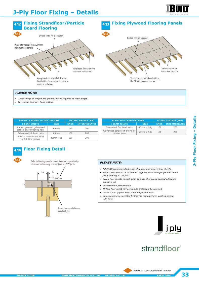
150mm centres on edges
200mm centres on immediate supports
Sheets layed in brick bond pattern.Use 50 x 8mm gauge screws.
Panel edge fixing 150mm maximum nail centres
Apply continuous bead of Holdfast Gorilla Grip Construction adhesive in addition to fixings.
Panel intermediate fixing 200mm maximum nail centres
Double fixing for diaphragm
Leave 1mm gap between panels at joint
Refer to flooring manufacturer’s literature required edge distances for fastening of sheet joint to LPI™ joists
8-10mm
EqEq
PLYWOOD FIXING OPTIONS FIXING CENTRES (MM)I-BEAM JOISTS SIZE ENDS INTERMEDIATES
Galvanised Flat head Nails 60mm x 2.8g 150 200
Galvanised screw self drilling or counter sunk 60mm x 2.8g 150 200
PARTICLE BOARD FIXING OPTIONS FIXING CENTRES (MM)I-BEAM JOISTS SIZE ENDS INTERMEDIATES
Annular grooved galvanised particle board flooring nails 60mm 150 200
Galvanised jolt head nails 60mm 150 200
Type 17 countersunk head self drilling screws 45mm x 8g 150 200
Refers to superceded detail number
Fixing Strandfloor/Particle Board Flooring
Floor Fixing Detail
Fixing Plywood Flooring Panels
PLEASE NOTE:
• NZWOODrecommendstheuseoftongueandgroovefloorsheets.
• Floorsheetsshouldbeinstalledstaggered,withalledgesparalleltothejoistsbearingonthejoist.
• Screwfloorsheetstoeachjoist.Theuseofproperlyappliedadequateadhesive will
• increasefloorperformance.
• Allfourfloorsheetcornersshouldpreferablybescrewed.
• Leave 10mm gap between sheet edges and walls.
• Unlessotherwisespecifiedbyflooringmanufacturer,applyfastenerswith 8mm
PLEASE NOTE:
• Timbernogsortongueandgroovejointisrequiredatsheetedges.
• Lay sheets in brick - bond pattern.
4.12 4.13
4.14
5.11
5.13
5.12
J-Ply Floor Fixing – Details
33
J-P
ly F
loor
Fix
ing
– D
etai
ls
APRIL 2014WWW.NZWOODPRODUCTS.CO.NZ PH: 0800 022 352DESIGN GUIDE
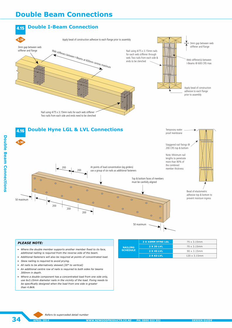
Nail using 4/75 x 3.15mm nails for each web stiffener Two nails from each side and ends need to be clenched
3mm gap between web stiffener and flange Web stiffeners between I-Beams at 600mm centres maximum
Apply bead of construction adhesive to each flange prior to assembly
At points of load concentration (eg girders) use a group of six nails as additional fasteners
Top & bottom faces of members must be carefully aligned
50 maximum
200200
200
200200
50 maximum
Web stiffener(s) between I-Beams @ 600 CRS max
3mm gap between web stiffener and flange
Nail using 4/75 x 3.15mm nails for each web stiffener through web. Two nails from each side & ends to be clenched
Apply bead of construction adhesive to each flange prior to assembly
Staggered nail fixings @ 200 CRS top & bottom
Note: Minimum nail lengths to penetrate more than 90% of the combined member thickness
Temporary water proof membrane
Bead of elastometric adhesive top & bottom to prevent moisture ingress
NAILING SCHEDULE
2 X 44MM HYNE LGL 75 x 3.15mm
2 X 35 LVL 70 x 3.15mm
2 X 45 LVL 90 x 3.15mm
2 X 63 LVL 120 x 3.15mm
Refers to superceded detail number
Double I-Beam Connection
Double Hyne LGL & LVL Connections
PLEASE NOTE:
• Wherethedoublemembersupportsanothermemberfixedtoitsface,additional nailing is required from the reverse side of the beam.
• Additional fasteners will also be required at points of concentrated load.
• Skewnailingisrequiredtoavoidprying.
• Allnailstobealternativelyskewed(30°tovertical)
• An additional centre row of nails is required to both sides for beams 300mm in depth.
• Whereadoublecomponenthasaconcentratedloadfromonesideonly,use6x3.15mmdiameternailsinthevicinityoftheload.Fixingneedstobespecificallydesignedwhentheloadfromonesideisgreaterthan 4.8kN.
4.15
4.16
5.29
5.30
Double Beam Connections
34
Dou
ble B
eam C
onn
ections
APRIL 2014 WWW.NZWOODPRODUCTS.CO.NZ PH: 0800 022 352 DESIGN GUIDE
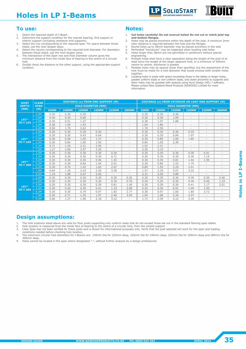
JOIST DEPTH (MM)
CLEAR SPAN (M)
DISTANCE (x) FROM END SUPPORT (M) DISTANCE (x) FROM INTERIOR OR CANT END SUPPORT (M)HOLE DIAMETER (MM) HOLE DIAMETER (MM)
50MM 100MM 150MM 165MM 225MM 280MM 50MM 100MM 150MM 165MM 225MM 280MM
LPI™ 70-T 225
2�0M 0.30 0.30 0.30 - - - 0.30 0.30 0.36 - - -3.0M 0.30 0.30 0.66 - - - 0.30 0.36 1.09 - - -4�0M 0.30 0.51 1.27 - - - 0.38 1.07 1.88 - - -5.0M 0.38 1.09 1.93 - - - 1�04 1.80 - - - -6.0M 0.94 1.70 2.62 - - - 1.78 2.59 - - - -
LPI™ 70-T 240
2�0M 0.30 0.30 0.30 0.30 - - 0.30 0.30 0.30 0.33 - -3.0M 0.30 0.30 0.43 0.64 - - 0.30 0.30 0.84 1.07 - -4�0M 0.30 0.30 1�02 1.27 - - 0.30 0.84 1.60 1.85 - -5.0M 0.30 0.84 1.65 1.93 - - 0.84 1.55 2.39 - - -6.0M 0.71 1.45 2.31 2.59 - - 1.52 2.31 - - - -7.0M 1.27 2.06 2.97 3.30 - - 2.26 3.10 - - - -
LPI™ 70-T 300
2�0M 0.30 0.30 0.30 0.30 0.30 - 0.30 0.30 0.30 0.30 0�41 -3.0M 0.30 0.30 0.30 0.30 0.71 - 0.30 0.30 0.30 0.30 1�14 -4�0M 0.30 0.30 0.30 0.46 1.32 - 0.30 0.30 0.81 1�02 1.93 -5.0M 0.30 0.30 0.84 1�04 2�01 - 0.30 0.84 1.52 1.75 - -6.0M 0.30 0.74 1�42 1.65 2.67 - 0.89 1.55 2.29 2.51 - -7.0M 0.64 1.30 2.03 2.29 3.38 - 1.57 2.29 3.07 3.33 - -8.0M 1.19 1.88 2.67 2.92 - - 2.31 3.05 3.89 - - -
LPI™ 70-T 356
2�0M 0.30 0.30 0.30 0.30 0.30 0.30 0.30 0.30 0.30 0.30 0.30 0.463.0M 0.30 0.30 0.30 0.30 0.30 0.76 0.30 0.30 0.30 0.30 0.46 1.194�0M 0.30 0.30 0.30 0.30 0.61 1�40 0.30 0.30 0.30 0�41 1.17 2�015.0M 0.30 0.30 0.30 0�41 1.19 2.08 0.30 0.30 0.91 1.09 1.93 -6.0M 0.30 0.30 0.79 0.97 1.83 2.77 0.38 0.97 1.60 1.80 2.72 -7.0M 0.30 0.71 1.35 1.57 2.46 3.45 1�04 1.68 2.34 2.57 - -8.0M 0.66 1.27 1.96 2.18 3.12 - 1.73 2.39 3.12 3.35 - -
To use:1� Select the required depth of I-Beam.2� Determine the support condition for the nearest bearing: End support or
interior support (including cantilever-end supports).3. Select the row corresponding to the required span. For spans between those
listed, use the next largest value.4� Select the column corresponding to the required hole diameter� For diameters
between those listed, use the next largest value.5. The intersection of the Span row and Hole Diameter column gives the
minimum distance from the inside face of bearing to the centre of a circular hole�
6. Double check the distance to the other support, using the appropriate support condition�
Notes:1� Cut holes carefully! Do not overcut holes! Do not cut or notch joist top
and bottom flanges.2� Holes may be placed anywhere within the depth of the joist. A minimum 2mm
clear distance is required between the hole and the flanges.3. Round holes up to 38mm diameter may be placed anywhere in the web4� Perforated “knockouts” may be neglected when locating web holes.5. Holes larger than 38mm are not permitted in cantilevers without special
engineering�6. Multiple holes shall have a clear separation along the length of the joist of at
least twice the length of the larger adjacent hole, or a minimum of 305mm centre-to-centre, whichever is greater.
7. Multiple holes may be spaced closer than specified, but the assessment of the hole must be made for a hole diameter that would enclose both smaller holes together�
8. Locating holes in joists with spans exceeding those in the tables or larger holes, greater uniform loads or non-uniform loads, and closer proximity to supports and other holes may be possible with analysis using Hyne Design (HD) 7 software. Please contact New Zealand Wood Products (NZWOOD) Limited for more information�
Design assumptions:1� The hole locations listed above are valid for floor joists supporting only uniform loads that do not exceed those set out in the standard flooring span tables. 2� Hole location is measured from the inside face of bearing to the centre of a circular hole, from the closest support.3. Clear Span has not been verified for these joists and is shown for informational purposes only. Verify that the joist selected will work for the span and loading
conditions needed before checking hole location.4� The maximum circular hole diameters for I-Beams are: 150mm Dia for 225mm deep, 165mm Dia for 240mm deep, 225mm Dia for 300mm deep and 280mm Dia for
356mm deep.5. Holes cannot be located in the span where designated “-”, without further analysis by a design professional.
Holes in LP I-Beams
35
Hol
es in
LP
I-B
eam
s
APRIL 2014WWW.NZWOODPRODUCTS.CO.NZ PH: 0800 022 352DESIGN GUIDE
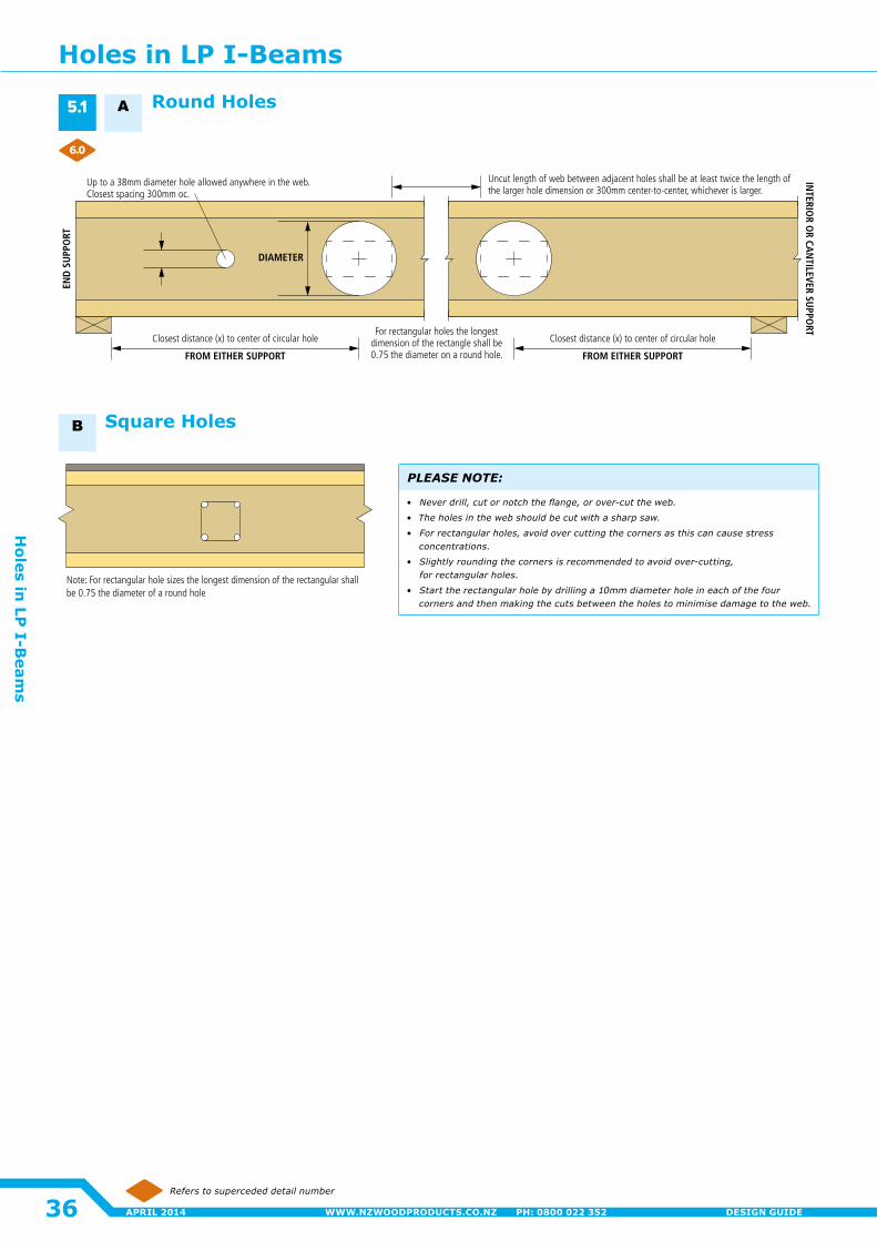
Note: For rectangular hole sizes the longest dimension of the rectangular shall be 0.75 the diameter of a round hole
Uncut length of web between adjacent holes shall be at least twice the length of the larger hole dimension or 300mm center-to-center, whichever is larger.
INTERIO
R OR CA
NTILEVER SU
PPORT
END
SU
PPO
RT
DIAMETER
FROM EITHER SUPPORT
Closest distance (x) to center of circular hole Closest distance (x) to center of circular holeFor rectangular holes the longest
dimension of the rectangle shall be 0.75 the diameter on a round hole.
Up to a 38mm diameter hole allowed anywhere in the web. Closest spacing 300mm oc.
FROM EITHER SUPPORT
Refers to superceded detail number
Square Holes
Round Holes
PLEASE NOTE:
• Neverdrill,cutornotchtheflange,orover-cuttheweb.
• The holes in the web should be cut with a sharp saw.
• Forrectangularholes,avoidovercuttingthecornersasthiscancausestressconcentrations.
• Slightlyroundingthecornersisrecommendedtoavoidover-cutting, for rectangular holes.
• Starttherectangularholebydrillinga10mmdiameterholeineachofthefourcorners and then making the cuts between the holes to minimise damage to the web.
5.1
6.0
A
B
Holes in LP I-Beams
36
Holes in
LP I-B
eams
APRIL 2014 WWW.NZWOODPRODUCTS.CO.NZ PH: 0800 022 352 DESIGN GUIDE
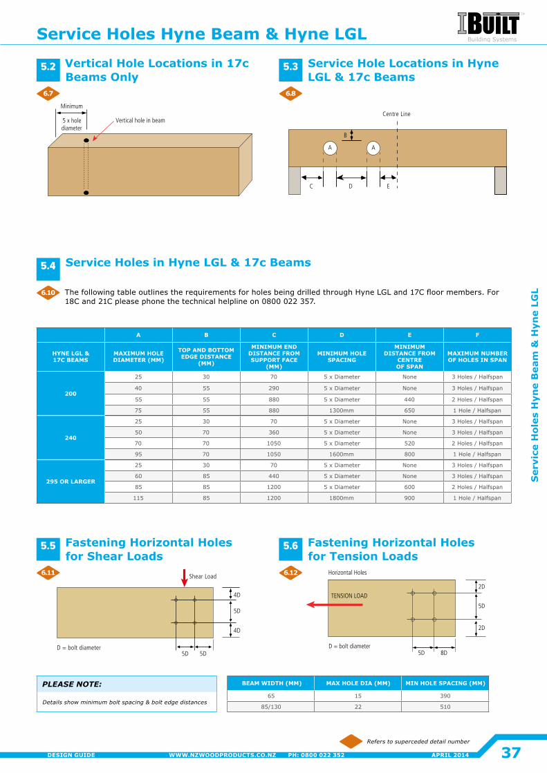
Vertical hole in beam
Minimum
5 x hole diameter
Centre Line
AA
C D E
B
D = bolt diameter
Shear Load
4D
5D
4D
5D 5D
Horizontal Holes
D = bolt diameter
TENSION LOAD
5D 8D
5D
2D
2D
A B C D E F
HYNE LGL & 17C BEAMS
MAXIMUM HOLE DIAMETER (MM)
TOP AND BOTTOM EDGE DISTANCE
(MM)
MINIMUM END DISTANCE FROM SUPPORT FACE
(MM)
MINIMUM HOLE SPACING
MINIMUM DISTANCE FROM
CENTRE OF SPAN
MAXIMUM NUMBER OF HOLES IN SPAN
200
25 30 70 5 x Diameter None 3 Holes / Halfspan
40 55 290 5 x Diameter None 3 Holes / Halfspan
55 55 880 5 x Diameter 440 2 Holes / Halfspan
75 55 880 1300mm 650 1 Hole / Halfspan
240
25 30 70 5 x Diameter None 3 Holes / Halfspan
50 70 360 5 x Diameter None 3 Holes / Halfspan
70 70 1050 5 x Diameter 520 2 Holes / Halfspan
95 70 1050 1600mm 800 1 Hole / Halfspan
295 OR LARGER
25 30 70 5 x Diameter None 3 Holes / Halfspan
60 85 440 5 x Diameter None 3 Holes / Halfspan
85 85 1200 5 x Diameter 600 2 Holes / Halfspan
115 85 1200 1800mm 900 1 Hole / Halfspan
BEAM WIDTH (MM) MAX HOLE DIA (MM) MIN HOLE SPACING (MM)
65 15 390
85/130 22 510
Refers to superceded detail number
PLEASE NOTE:
Details show minimum bolt spacing & bolt edge distances
Vertical Hole Locations in 17c Beams Only
Service Hole Locations in Hyne LGL & 17c Beams
The following table outlines the requirements for holes being drilled through Hyne LGL and 17C floor members. For 18C and 21C please phone the technical helpline on 0800 022 357.
Service Holes in Hyne LGL & 17c Beams
Fastening Horizontal Holes for Shear Loads
Fastening Horizontal Holes for Tension Loads
5.2 5.3
5.4
5.5 5.6
6.7
6.11
6.10
6.8
6.12
Service Holes Hyne Beam & Hyne LGL
37
Ser
vice
Hol
es H
yne
Bea
m &
Hyn
e LG
L
APRIL 2014WWW.NZWOODPRODUCTS.CO.NZ PH: 0800 022 352DESIGN GUIDE
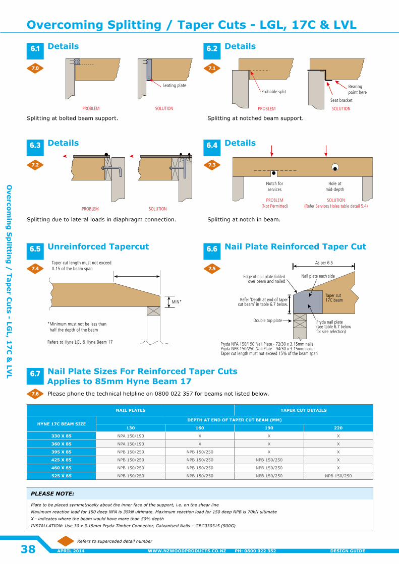
Taper cut 17C beam
Edge of nail plate foldedover beam and nailed
Nail plate each side
As per 6.5
Pryda nail plate (see table 6.7 belowfor size selection)
Refer ‘Depth at end of tapercut beam’ in table 6.7 below.
Double top plate
Pryda NPA 150/190 Nail Plate - 72/30 x 3.15mm nailsPryda NPB 150/250 Nail Plate - 94/30 x 3.15mm nailsTaper cut length must not exceed 15% of the beam span
PROBLEM SOLUTION
Seating plateProbable split
PROBLEM
Seat bracket
Bearingpoint here
SOLUTION
MIN*
*Minimum must not be less than half the depth of the beam
Refers to Hyne LGL & Hyne Beam 17
Taper cut length must not exceed 0.15 of the beam span
PROBLEM SOLUTION
Hole at mid-depth
Notch forservices
PROBLEM(Not Permitted)
SOLUTION(Refer Services Holes table detail 5.4)
NAIL PLATES TAPER CUT DETAILS
HYNE 17C BEAM SIZE DEPTH AT END OF TAPER CUT BEAM (MM)
130 160 190 220
330 X 85 NPA 150/190 X X X
360 X 85 NPA 150/190 X X X
395 X 85 NPB 150/250 NPB 150/250 X X
425 X 85 NPB 150/250 NPB 150/250 NPB 150/250 X
460 X 85 NPB 150/250 NPB 150/250 NPB 150/250 X
525 X 85 NPB 150/250 NPB 150/250 NPB 150/250 NPB 150/250
Refers to superceded detail number
Nail Plate Sizes For Reinforced Taper Cuts Applies to 85mm Hyne Beam 17
PLEASE NOTE:
Platetobeplacedsymmetricallyabouttheinnerfaceofthesupport,i.e.ontheshearline
Maximumreactionloadfor150deepNPAis35kNultimate.Maximumreactionloadfor150deepNPBis70kNultimate
X - indicates where the beam would have more than 50% depth
INSTALLATION:Use30x3.15mmPrydaTimberConnector,GalvanisedNails–GBC030315(500G)
Details Details
Nail Plate Reinforced Taper CutUnreinforced Tapercut
Details Details
Please phone the technical helpline on 0800 022 357 for beams not listed below.
Splitting at bolted beam support. Splitting at notched beam support.
Splitting due to lateral loads in diaphragm connection� Splitting at notch in beam.
6.1
6.3
6.5
6.7
6.2
6.4
6.6
7.0
7.2
7.4
7.6
7.1
7.3
7.5
Overcoming Splitting / Taper Cuts - LGL, 17C & LVL
38
Overcom
ing
Sp
litting
/ Tap
er Cu
ts - LGL, 1
7C
& LV
L
APRIL 2014 WWW.NZWOODPRODUCTS.CO.NZ PH: 0800 022 352 DESIGN GUIDE
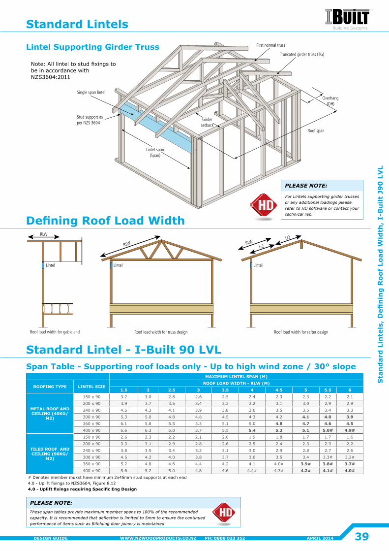
Lintel span(Span)
Single span lintel
Stud support as per NZS 3604
Overhang(OH)
Roof span
Girdersetback
Truncated girder truss (TG)
First normal truss
Lintel
RLW
Roof load width for gable end Roof load width for truss design
Lintel
RLW
Roof load width for rafter design
Lintel
1/2
1/2RLW
MAXIMUM LINTEL SPAN (M)
ROOFING TYPE LINTEL SIZEROOF LOAD WIDTH - RLW (M)
1.5 2 2.5 3 3.5 4 4.5 5 5.5 6
METAL ROOF AND CEILING (40KG/
M2)
150 x 90 3.2 3.0 2.8 2.6 2.5 2�4 2.3 2.3 2�2 2�1
200 x 90 3.9 3.7 3.5 3.4 3.3 3.2 3.1 3.0 2.9 2.9
240 x 90 4.5 4.3 4�1 3.9 3.8 3.6 3.5 3.5 3.4 3.3
300 x 90 5.3 5.0 4.8 4.6 4.5 4.3 4�2 4.1 4.0 3.9360 x 90 6.1 5.8 5.5 5.3 5.1 5.0 4.8 4.7 4.6 4.5400 x 90 6.6 6.3 6.0 5.7 5.5 5.4 5.2 5.1 5.0# 4.9#
TILED ROOF AND CEILING (90KG/
M2)
150 x 90 2.6 2.3 2�2 2�1 2�0 1.9 1.8 1.7 1.7 1.6
200 x 90 3.3 3.1 2.9 2.8 2.6 2.5 2�4 2.3 2.3 2�2
240 x 90 3.8 3.5 3.4 3.2 3.1 3.0 2.9 2.8 2.7 2.6
300 x 90 4.5 4�2 4�0 3.8 3.7 3.6 3.5 3.4 3.3# 3.2#
360 x 90 5.2 4.8 4.6 4�4 4�2 4�1 4.0# 3.9# 3.8# 3.7#400 x 90 5.6 5.2 5.0 4.8 4.6 4.4# 4.3# 4.2# 4.1# 4.0#
# Denotes member muxst have minimum 2x45mm stud supports at each end4.0 - Uplift fixings to NZS3604, Figure 8.124.0 - Uplift fixings requiring Specific Eng Design
PLEASE NOTE:Thesespantablesprovidemaximummemberspansto100%oftherecommendedcapacity.Itisrecommendedthatdeflectionislimitedto5mmtoensurethecontinuedperformanceofitemssuchasBifoldingdoorjoineryismaintained
PLEASE NOTE:
For Lintels supporting girder trusses or any additional loadings please refer to HD software or contact your technical rep.
Lintel Supporting Girder Truss
Note: All lintel to stud fixings to be in accordance with NZS3604:2011
Span Table - Supporting roof loads only - Up to high wind zone / 30° slope
Standard Lintels
Standard Lintel - I-Built 90 LVL
Defining Roof Load Width
39
Sta
nd
ard
Lin
tels
, D
efin
ing
Roo
f Lo
ad W
idth
, I-
Bu
ilt J
90
LV
L
APRIL 2014WWW.NZWOODPRODUCTS.CO.NZ PH: 0800 022 352DESIGN GUIDE
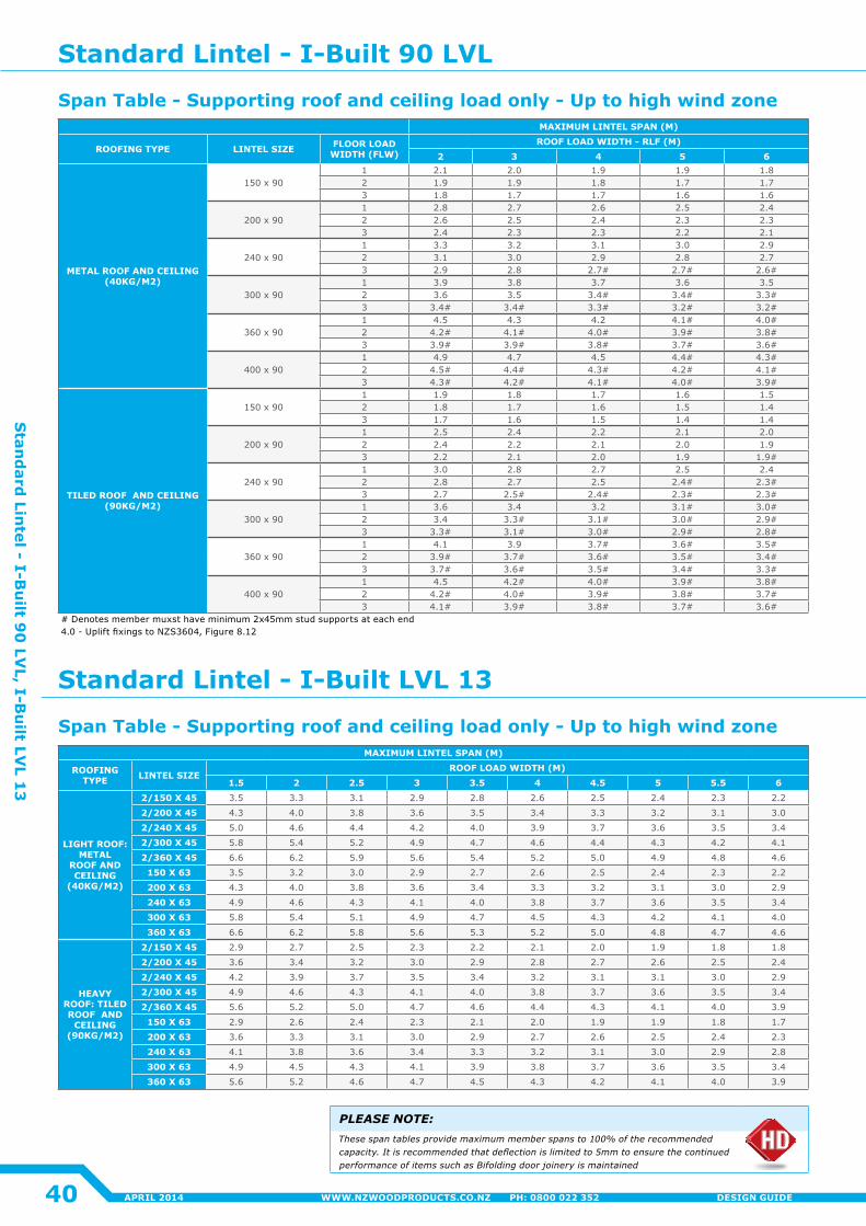
MAXIMUM LINTEL SPAN (M)
ROOFING TYPE LINTEL SIZE
ROOF LOAD WIDTH (M)1.5 2 2.5 3 3.5 4 4.5 5 5.5 6
LIGHT ROOF: METAL
ROOF AND CEILING
(40KG/M2)
2/150 X 45 3.5 3.3 3.1 2.9 2.8 2.6 2.5 2�4 2.3 2�2
2/200 X 45 4.3 4�0 3.8 3.6 3.5 3.4 3.3 3.2 3.1 3.0
2/240 X 45 5.0 4.6 4�4 4�2 4�0 3.9 3.7 3.6 3.5 3.4
2/300 X 45 5.8 5.4 5.2 4.9 4.7 4.6 4�4 4.3 4�2 4�1
2/360 X 45 6.6 6.2 5.9 5.6 5.4 5.2 5.0 4.9 4.8 4.6
150 X 63 3.5 3.2 3.0 2.9 2.7 2.6 2.5 2�4 2.3 2�2
200 X 63 4.3 4�0 3.8 3.6 3.4 3.3 3.2 3.1 3.0 2.9
240 X 63 4.9 4.6 4.3 4�1 4�0 3.8 3.7 3.6 3.5 3.4
300 X 63 5.8 5.4 5.1 4.9 4.7 4.5 4.3 4�2 4�1 4�0
360 X 63 6.6 6.2 5.8 5.6 5.3 5.2 5.0 4.8 4.7 4.6
HEAVY ROOF: TILED ROOF AND
CEILING (90KG/M2)
2/150 X 45 2.9 2.7 2.5 2.3 2�2 2�1 2�0 1.9 1.8 1.8
2/200 X 45 3.6 3.4 3.2 3.0 2.9 2.8 2.7 2.6 2.5 2�4
2/240 X 45 4�2 3.9 3.7 3.5 3.4 3.2 3.1 3.1 3.0 2.9
2/300 X 45 4.9 4.6 4.3 4�1 4�0 3.8 3.7 3.6 3.5 3.4
2/360 X 45 5.6 5.2 5.0 4.7 4.6 4�4 4.3 4�1 4�0 3.9
150 X 63 2.9 2.6 2�4 2.3 2�1 2�0 1.9 1.9 1.8 1.7
200 X 63 3.6 3.3 3.1 3.0 2.9 2.7 2.6 2.5 2�4 2.3
240 X 63 4�1 3.8 3.6 3.4 3.3 3.2 3.1 3.0 2.9 2.8
300 X 63 4.9 4.5 4.3 4�1 3.9 3.8 3.7 3.6 3.5 3.4
360 X 63 5.6 5.2 4.6 4.7 4.5 4.3 4�2 4�1 4�0 3.9
MAXIMUM LINTEL SPAN (M)
ROOFING TYPE LINTEL SIZE FLOOR LOAD WIDTH (FLW)
ROOF LOAD WIDTH - RLF (M)2 3 4 5 6
METAL ROOF AND CEILING (40KG/M2)
150 x 901 2�1 2�0 1.9 1.9 1.82 1.9 1.9 1.8 1.7 1.73 1.8 1.7 1.7 1.6 1.6
200 x 901 2.8 2.7 2.6 2.5 2�42 2.6 2.5 2�4 2.3 2.33 2�4 2.3 2.3 2�2 2�1
240 x 901 3.3 3.2 3.1 3.0 2.92 3.1 3.0 2.9 2.8 2.73 2.9 2.8 2.7# 2.7# 2.6#
300 x 901 3.9 3.8 3.7 3.6 3.52 3.6 3.5 3.4# 3.4# 3.3#3 3.4# 3.4# 3.3# 3.2# 3.2#
360 x 901 4.5 4.3 4�2 4.1# 4.0#2 4.2# 4.1# 4.0# 3.9# 3.8#3 3.9# 3.9# 3.8# 3.7# 3.6#
400 x 901 4.9 4.7 4.5 4.4# 4.3#2 4.5# 4.4# 4.3# 4.2# 4.1#3 4.3# 4.2# 4.1# 4.0# 3.9#
TILED ROOF AND CEILING (90KG/M2)
150 x 901 1.9 1.8 1.7 1.6 1.52 1.8 1.7 1.6 1.5 1�43 1.7 1.6 1.5 1�4 1�4
200 x 901 2.5 2�4 2�2 2�1 2�02 2�4 2�2 2�1 2�0 1.93 2�2 2�1 2�0 1.9 1.9#
240 x 901 3.0 2.8 2.7 2.5 2�42 2.8 2.7 2.5 2.4# 2.3#3 2.7 2.5# 2.4# 2.3# 2.3#
300 x 901 3.6 3.4 3.2 3.1# 3.0#2 3.4 3.3# 3.1# 3.0# 2.9#3 3.3# 3.1# 3.0# 2.9# 2.8#
360 x 901 4�1 3.9 3.7# 3.6# 3.5#2 3.9# 3.7# 3.6# 3.5# 3.4#3 3.7# 3.6# 3.5# 3.4# 3.3#
400 x 901 4.5 4.2# 4.0# 3.9# 3.8#2 4.2# 4.0# 3.9# 3.8# 3.7#3 4.1# 3.9# 3.8# 3.7# 3.6#
# Denotes member muxst have minimum 2x45mm stud supports at each end4.0 - Uplift fixings to NZS3604, Figure 8.12
PLEASE NOTE:Thesespantablesprovidemaximummemberspansto100%oftherecommendedcapacity.Itisrecommendedthatdeflectionislimitedto5mmtoensurethecontinuedperformanceofitemssuchasBifoldingdoorjoineryismaintained
Standard Lintel - I-Built LVL 13
Standard Lintel - I-Built 90 LVL
Span Table - Supporting roof and ceiling load only - Up to high wind zone
Span Table - Supporting roof and ceiling load only - Up to high wind zone
40
Stan
dard
Lintel - I-B
uilt 9
0 LV
L, I-Bu
ilt LVL 1
3
APRIL 2014 WWW.NZWOODPRODUCTS.CO.NZ PH: 0800 022 352 DESIGN GUIDE
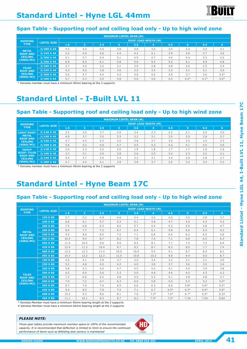
MAXIMUM LINTEL SPAN (M)
ROOFING TYPE LINTEL SIZE
ROOF LOAD WIDTH (M)1.5 2 2.5 3 3.5 4 4.5 5 5.5 6
METAL ROOF AND CEILING
(40KG/M2)
195 X 85 5.7 5.2 4.9 4.6 4�4 4�2 4�0 3.9 3.8 3.7
230 X 85 6.6 6.1 5.7 5.3 5.1 4.8 4.7 4.5 4.3 4�2
260 X 85 7.5 6.8 6.3 6.0 5.7 5.4 5.2 5.0 4.8 4.7
295 X 85 8.4 7.7 7.2 6.7 6.4 6.1 5.8 5.6 5.4 5.2
330 X 85 9.5 8.6 8.0 7.5 7.1 6.8 6.5 6.2 6.0 5.8
360 X 85 10�4 9.4 8.7 8.2 7.8 7.4 7.1 6.8 6.5 6.3
395 X 85 11�4 10�4 9.6 9.0 8.5 8.1 7.7 7.4 7.2 6.9
425 X 85 12�4 11.3 10�4 9.7 9.2 8.7 8.3 8.0 7.7 7.4
460 X 85 13.5 12.3 11�4 10.6 10�0 9.5 9.1 8.7 8.4 8.1
495 X 85 14.7 13.3 12.3 11.5 10.8 10.3 9.8 9.4 9.0 8.7
TILED ROOF AND CEILING
(90KG/M2)
195 X 85 4.5 4�1 3.9 3.7 3.5 3.4 3.2 3.1 3.1 3.0
230 X 85 5.2 4.8 4.5 4�2 4�0 3.9 3.7 3.6 3.5 3.4
260 X 85 5.8 5.3 5.0 4.7 4.5 4.3 4�1 4�0 3.9 3.8
295 X 85 6.5 6.0 5.6 5.3 5.0 4.8 4.6 4.5 4.3 4�2
330 X 85 7.3 6.6 6.2 5.8 5.5 5.3 5.1 4.9 4.8 4.7
360 X 85 7.9 7.2 6.7 6.3 6.0 5.8 5.5 5.3 5.2 5.0*
395 X 85 8.7 7.9 7.4 6.9 6.6 6.3 6.0 5.8* 5.6* 5.5*
425 X 85 9.4 8.5 7.9 7.4 7.1 6.7 6.5* 6.3* 6.0* 5.9*
460 X 85 10�2 9.3 8.6 8.1 7.6 7.3* 7.0* 6.7* 6.5* 6.3#
495 X 85 11�1 10�1 9.3 8.7 8.2 7.9* 7.5* 7.3# 7.0# 6.8#
* Denotes Member must have a minimum 45mm bearing length at the 2 supports# Denotes Member must have a minimum 65mm bearing length at the 2 supports
MAXIMUM LINTEL SPAN (M)
ROOFING TYPE LINTEL SIZE
ROOF LOAD WIDTH (M)1.5 2 2.5 3 3.5 4 4.5 5 5.5 6
METAL ROOF AND CEILING
(40KG/M2)
2/200 X 44 4.5 4�2 4�0 3.8 3.6 3.5 3.4 3.3 3.2 3.1
2/245 X 44 5.2 4.9 4.6 4�4 4�2 4�1 3.9 3.8 3.7 3.6
2/300 X 44 6.1 5.7 5.4 5.1 4.9 4.7 4.6 4�4 4.3 4�2
2/360 X 44 6.9 6.5 6.1 5.8 5.6 5.4 5.2 5.1 4.9 4.8
TILED ROOF AND CEILING
(90KG/M2)
2/200 X 44 3.7 3.4 3.2 3.1 3.0 2.8 2.8 2.6 2.5 2�4
2/245 X 44 4.3 4�0 3.8 3.6 3.5 3.5 3.3 3.1 3.1 3.0
2/300 X 44 5.0 4.7 4�4 4�2 4�0 4�0 3.9 3.7 3.6 3.5*
2/360 X 44 5.7 5.3 5.0 4.8 4.6 4.6 4.5 4.2* 4.1* 4.0*
* Denotes member must have a minimum 45mm bearing at the 2 supports
MAXIMUM LINTEL SPAN (M)
ROOFING TYPE LINTEL SIZE
ROOF LOAD WIDTH (M)1.5 2 2.5 3 3.5 4 4.5 5 5.5 6
LIGHT ROOF: METAL
ROOF AND CEILING
(40KG/M2)
2/140 X 45 3.2 3.0 2.7 2.6 2�4 2.3 2�2 2�1 2�0 2�0
2/190 X 45 4�0 3.7 3.5 3.3 3.2 3.1 3.0 2.9 2.8 2.7
2/240 X 45 4.7 4�4 4�2 4�0 3.8 3.7 3.6 3.5 3.4 3.3
2/300 X 45 5.6 5.2 4.9 4.7 4.5 4.3 4�2 4�1 4�0 3.9
HEAVY ROOF: TILED ROOF AND CEILING
(90KG/M2)
2/140 X 45 2.6 2.3 2�2 2�0 1.9 1.8 1.7 1.7 1.6 1.6
2/190 X 45 3.3 3.1 2.9 2.8 2.6 2.5 2�4 2.3 2�2 2�1
2/240 X 45 4�0 3.7 3.5 3.3 3.2 3.1 3.0 2.9 2.8 2.7
2/300 X 45 4.7 4�4 4�1 3.9 3.8 3.7 3.5 3.4 3.4 3.3
* Denotes member must have a minimum 45mm bearing at the 2 supports
PLEASE NOTE:Thesespantablesprovidemaximummemberspansto100%oftherecommendedcapacity.Itisrecommendedthatdeflectionislimitedto5mmtoensurethecontinuedperformanceofitemssuchasBifoldingdoorjoineryismaintained
Standard Lintel - I-Built LVL 11
Standard Lintel - Hyne Beam 17C
Span Table - Supporting roof and ceiling load only - Up to high wind zone
Span Table - Supporting roof and ceiling load only - Up to high wind zone
Span Table - Supporting roof and ceiling load only - Up to high wind zone
Standard Lintel - Hyne LGL 44mm
41
Sta
nd
ard
Lin
tel -
Hyn
e LG
L 4
4,
I-B
uilt
LV
L 1
1,
Hyn
e B
eam
17
C
APRIL 2014WWW.NZWOODPRODUCTS.CO.NZ PH: 0800 022 352DESIGN GUIDE
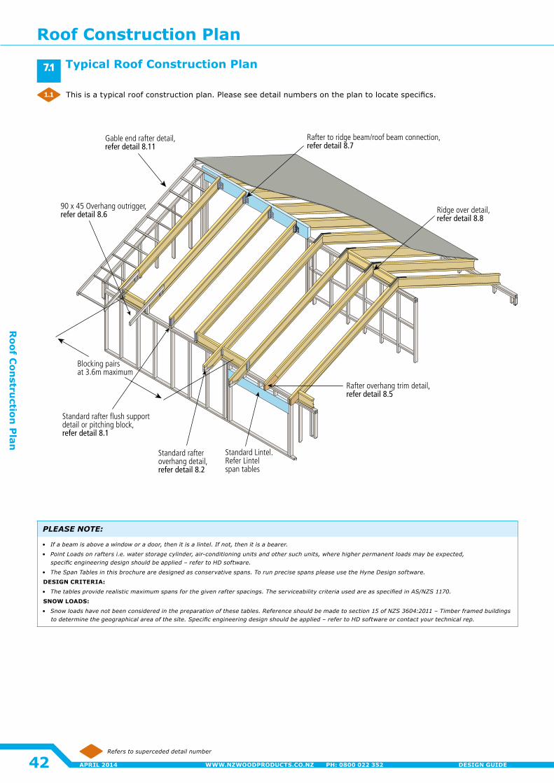
Standard Lintel. Refer Lintel span tables
Standard rafter flush supportdetail or pitching block, refer detail 8.1
Standard rafteroverhang detail,refer detail 8.2
Blocking pairsat 3.6m maximum
90 x 45 Overhang outrigger,refer detail 8.6
Rafter overhang trim detail, refer detail 8.5
Ridge over detail,refer detail 8.8
Rafter to ridge beam/roof beam connection,refer detail 8.7
Gable end rafter detail, refer detail 8.11
Refers to superceded detail number
This is a typical roof construction plan. Please see detail numbers on the plan to locate specifics.
PLEASE NOTE:
• Ifabeamisaboveawindoworadoor,thenitisalintel.Ifnot,thenitisabearer.
• PointLoadsonraftersi.e.waterstoragecylinder,air-conditioningunitsandothersuchunits,wherehigherpermanentloadsmaybeexpected, specificengineeringdesignshouldbeapplied–refertoHDsoftware.
• TheSpanTablesinthisbrochurearedesignedasconservativespans.TorunprecisespanspleaseusetheHyneDesignsoftware.
DESIGN CRITERIA:
• Thetablesproviderealisticmaximumspansforthegivenrafterspacings.TheserviceabilitycriteriausedareasspecifiedinAS/NZS1170.
SNOW LOADS:
• Snowloadshavenotbeenconsideredinthepreparationofthesetables.Referenceshouldbemadetosection15ofNZS3604:2011–Timberframedbuildingstodeterminethegeographicalareaofthesite.Specificengineeringdesignshouldbeapplied–refertoHDsoftwareorcontactyourtechnicalrep.
Typical Roof Construction Plan7.1
1.1
Roof Construction Plan
42
Roof C
onstru
ction P
lan
APRIL 2014 WWW.NZWOODPRODUCTS.CO.NZ PH: 0800 022 352 DESIGN GUIDE
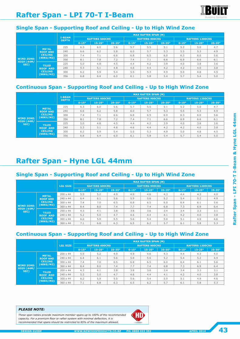
I-BEAM DEPTH
MAX RAFTER SPAN (M)RAFTERS 600CRS RAFTERS 900CRS RAFTERS 1200CRS
0-15° 15-25° 25-35° 0-15° 15-25° 25-35° 0-15° 15-25° 25-35°
WIND ZONE: HIGH (44M/
SEC)
METAL ROOF AND CEILING
(40KG/M2)
225 6.3 6.0 5.6 5.7 5.5 5.1 5.2 5.0 4.7
240 6.6 6.2 5.8 6.0 5.7 5.3 5.5 5.3 4.9
300 7.4 7.1 6.6 6.8 6.5 6.0 6.3 6.0 5.6
356 8.1 7.8 7.2 7.4 7.1 6.6 6.9 6.6 6.1
TILED ROOF AND
CEILING (90KG/M2)
225 5.0 4.8 4.5 4�4 4�2 3.9 4�0 3.8 3.6
240 5.3 5.1 4.8 4.6 4�4 4�2 4�2 4�0 3.8
300 6.2 5.9 5.4 5.5 5.3 4.9 5.0 4.8 4.5
356 6.8 6.4 6.0 6.1 5.8 5.4 5.7 5.4 5.0
LGL SIZEMAX RAFTER SPAN (M)
RAFTERS 600CRS RAFTERS 900CRS RAFTERS 1200CRS0-15° 15-25° 25-35° 0-15° 15-25° 25-35° 0-15° 15-25° 25-35°
WIND ZONE: HIGH (44M/
SEC)
METAL ROOF AND CEILING
(40KG/M2)
200 x 44 5.5 5.2 4.9 4.9 4.6 4.3 4�4 4.3 4�0
240 x 44 6.4 6.1 5.6 5.9 5.6 5.2 5.4 5.2 4.9
300 x 44 7.4 7.0 6.5 6.8 6.5 6.0 6.4 6.1 5.6
360 x 44 8.4 8.0 7.4 7.7 7.4 6.8 7.3 6.9 6.4
TILED ROOF AND
CEILING (90KG/M2)
200 x 44 4.3 4�1 3.8 3.8 3.6 3.4 3.4 3.3 3.1
240 x 44 5.2 5.0 4.7 4.6 4�4 4�1 4�2 4�0 3.8
300 x 44 6.2 5.9 5.5 5.6 5.4 5.0 5.1 4.9 4.6
360 x 44 7.1 6.8 6.3 6.5 6.2 5.7 6.1 5.8 5.3
PLEASE NOTE:These span tables provide maximum member spans up to 100% of the recommended capacity. For a premium floor or rafter system with minimal deflection, it is recommended that spans should be restricted to 85% of the maximum allowed.
Single Span - Supporting Roof and Ceiling - Up to High Wind Zone
Single Span - Supporting Roof and Ceiling - Up to High Wind Zone
Continuous Span - Supporting Roof and Ceiling - Up to High Wind Zone
Continuous Span - Supporting Roof and Ceiling - Up to High Wind Zone
Rafter Span - LPI 70-T I-Beam
Rafter Span - Hyne LGL 44mm
43
Raf
ter
Sp
an -
LP
I 7
0-T
I-B
eam
& H
yne
LGL
44
mm
APRIL 2014WWW.NZWOODPRODUCTS.CO.NZ PH: 0800 022 352DESIGN GUIDE
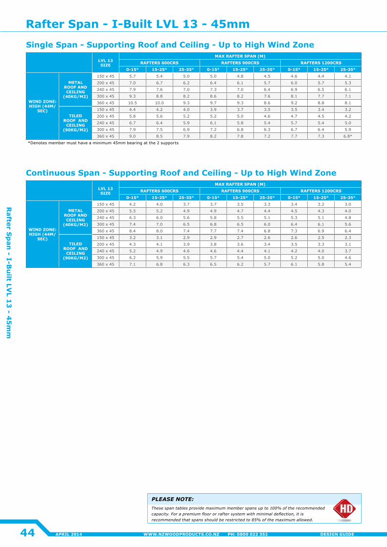
LVL 13 SIZE
MAX RAFTER SPAN (M)RAFTERS 600CRS RAFTERS 900CRS RAFTERS 1200CRS
0-15° 15-25° 25-35° 0-15° 15-25° 25-35° 0-15° 15-25° 25-35°
WIND ZONE: HIGH (44M/
SEC)
METAL ROOF AND CEILING
(40KG/M2)
150 x 45 5.7 5.4 5.0 5.0 4.8 4.5 4.6 4�4 4�1
200 x 45 7.0 6.7 6.2 6.4 6.1 5.7 6.0 5.7 5.3
240 x 45 7.9 7.6 7.0 7.3 7.0 6.4 6.9 6.5 6.1
300 x 45 9.3 8.8 8.2 8.6 8.2 7.6 8.1 7.7 7.1
360 x 45 10.5 10�0 9.3 9.7 9.3 8.6 9.2 8.8 8.1
TILED ROOF AND
CEILING (90KG/M2)
150 x 45 4�4 4�2 4�0 3.9 3.7 3.5 3.5 3.4 3.2
200 x 45 5.8 5.6 5.2 5.2 5.0 4.6 4.7 4.5 4�2
240 x 45 6.7 6.4 5.9 6.1 5.8 5.4 5.7 5.4 5.0
300 x 45 7.9 7.5 6.9 7.2 6.8 6.3 6.7 6.4 5.9
360 x 45 9.0 8.5 7.9 8.2 7.8 7.2 7.7 7.3 6.8*
*Denotes member must have a minimum 45mm bearing at the 2 supports
LVL 13 SIZE
MAX RAFTER SPAN (M)RAFTERS 600CRS RAFTERS 900CRS RAFTERS 1200CRS
0-15° 15-25° 25-35° 0-15° 15-25° 25-35° 0-15° 15-25° 25-35°
WIND ZONE: HIGH (44M/
SEC)
METAL ROOF AND CEILING
(40KG/M2)
150 x 45 4�2 4�0 3.7 3.7 3.5 3.3 3.4 3.2 3.0
200 x 45 5.5 5.2 4.9 4.9 4.7 4�4 4.5 4.3 4�0
240 x 45 6.3 6.0 5.6 5.8 5.5 5.1 5.3 5.1 4.8
300 x 45 7.4 7.0 6.5 6.8 6.5 6.0 6.4 6.1 5.6
360 x 45 8.4 8.0 7.4 7.7 7.4 6.8 7.3 6.9 6.4
TILED ROOF AND
CEILING (90KG/M2)
150 x 45 3.2 3.1 2.9 2.9 2.7 2.6 2.6 2.5 2.3
200 x 45 4.3 4�1 3.9 3.8 3.6 3.4 3.5 3.3 3.1
240 x 45 5.2 4.9 4.6 4.6 4�4 4�1 4�2 4�0 3.7
300 x 45 6.2 5.9 5.5 5.7 5.4 5.0 5.2 5.0 4.6
360 x 45 7.1 6.8 6.3 6.5 6.2 5.7 6.1 5.8 5.4
PLEASE NOTE:These span tables provide maximum member spans up to 100% of the recommended capacity. For a premium floor or rafter system with minimal deflection, it is recommended that spans should be restricted to 85% of the maximum allowed.
Single Span - Supporting Roof and Ceiling - Up to High Wind Zone
Continuous Span - Supporting Roof and Ceiling - Up to High Wind Zone
Rafter Span - I-Built LVL 13 - 45mm
44
Rafter S
pan
- I-Bu
ilt LVL 1
3 - 4
5m
m
APRIL 2014 WWW.NZWOODPRODUCTS.CO.NZ PH: 0800 022 352 DESIGN GUIDE
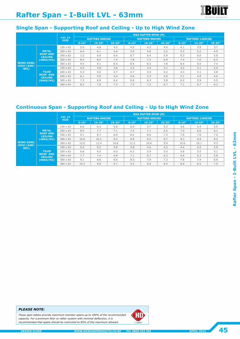
LVL 13 SIZE
MAX RAFTER SPAN (M)RAFTERS 600CRS RAFTERS 900CRS RAFTERS 1200CRS
0-15° 15-25° 25-35° 0-15° 15-25° 25-35° 0-15° 15-25° 25-35°
WIND ZONE: HIGH (44M/
SEC)
METAL ROOF AND CEILING
(40KG/M2)
150 x 63 5.0 4.8 4.5 4.5 4.3 4�0 4�1 3.9 3.7
200 x 63 6.4 6.1 5.6 5.9 5.6 5.2 5.5 5.2 4.9
240 x 63 7.2 6.9 6.4 6.7 6.4 5.9 6.3 6.0 5.6
300 x 63 8.4 8.0 7.4 7.8 7.5 6.9 7.4 7.0 6.5
360 x 63 9.5 9.1 8.4 8.9 8.5 7.8 8.4 8.0 7.4
TILED ROOF AND
CEILING (90KG/M2)
150 x 63 4�0 3.8 3.6 3.5 3.4 3.1 3.2 3.1 2.9
200 x 63 5.3 5.0 4.7 4.7 4.5 4�2 4.3 4�1 3.8
240 x 63 6.1 5.9 5.4 5.6 5.3 5.0 5.1 4.9 4.6
300 x 63 7.2 6.9 6.4 6.6 6.3 5.8 6.2 5.9 5.5
360 x 63 8.2 7.8 7.2 7.5 7.2 6.7 7.1 6.7 6.2
LVL 13 SIZE
MAX RAFTER SPAN (M)RAFTERS 600CRS RAFTERS 900CRS RAFTERS 1200CRS
0-15° 15-25° 25-35° 0-15° 15-25° 25-35° 0-15° 15-25° 25-35°
WIND ZONE: HIGH (44M/
SEC)
METAL ROOF AND CEILING
(40KG/M2)
150 x 63 6.6 6.3 5.8 6.0 5.7 5.3 5.6 5.4 5.0
200 x 63 8.0 7.7 7.1 7.4 7.1 6.5 7.0 6.6 6.1
240 x 63 9.1 8.7 8.0 8.4 8.0 7.4 7.9 7.6 7.0
300 x 63 10.6 10�1 9.4 9.8 9.4 8.7 9.3 8.9 8.2
360 x 63 12�0 11�4 10.6 11�2 10.6 9.9 10.6 10�1 9.3
TILED ROOF AND
CEILING (90KG/M2)
150 x 63 5.4 5.2 4.8 4.8 4.6 4.3 4�4 4�2 3.9
200 x 63 6.8 6.5 6.0 6.2 5.9 5.5 5.8 5.5 5.1
240 x 63 7.7 7.4 6.8 7.1 6.7 6.2 6.6 6.3 5.8
300 x 63 9.1 8.6 8.0 8.3 7.9 7.3 7.8 7.4 6.9
360 x 63 10.3 9.8 9.1 9.5 9.0 8.4 8.9 8.5 7.9
PLEASE NOTE:These span tables provide maximum member spans up to 100% of the recommended capacity. For a premium floor or rafter system with minimal deflection, it is recommended that spans should be restricted to 85% of the maximum allowed.
Single Span - Supporting Roof and Ceiling - Up to High Wind Zone
Continuous Span - Supporting Roof and Ceiling - Up to High Wind Zone
Rafter Span - I-Built LVL - 63mm
45
Raf
ter
Sp
an -
I-B
uilt
LV
L -
63
mm
APRIL 2014WWW.NZWOODPRODUCTS.CO.NZ PH: 0800 022 352DESIGN GUIDE

70 x 30 Web stiffeners, nail with 3/65 x 3.15 nails each side equally spaced.
Web stiffeners required each side of I-Beam bevel cut. Stiffeners to match roof pitch.
Fix in accordance with tie-downrequirements of NZS3604. Refer detail 8.14
70 x 120 Pitching block or bevel top plate. To match pitch (Note pitching block method preferred)
70 x 35 Nailing block to side of web
I-Beam rafter
Fascia
OPTION 1
OPTION 2
900mm Maximum overhang250mm Maximum taper cut
90mm Minimum
Web stiffeners,nail using 3/65 x 3.15mm nails from each side
900mm Maximum overhangwhen flange trimmed
70 x 120 Pitching blockor bevel top plate
ALTERNATIVE OPTION RB21 Rimboard ripped down and fixed to both sides with 65 x 3.15 FH nails at 150mm centres along top and bottom
Note: Greater eave overhangs can be achieved when designing rafters using the HD7 software
300mm Minimum
Pryda NPA to both sides.(Web stiffeners req)
Web stiffener
Pitch
Pryda NPA to both sides. (web stiffeners required)
Beam
Top Plate
I-Beam rafter
Birdsmouth cut at support, not deeper than 1/2 of flange thickness (16mm) Note: Min bearing at external support 32mm
ALTERNATIVE OPTION RB21 Rimboard ripped down and fix to both sides with 65 x 3.15 FH nails at150mm centres along top and bottom.
Rafter centres1200mm maximum light weight900mm maximum heavy weightWeb stiffeners
Web stiffeners for fascia support
Nail using 3/65 x 3.15mm nails from each side at each block
Nail using 3/65 x 3.15mm nails from each side on each block at 600mm centres.
600mm Maximum
Rafter centres1200mm maximum light weight900mm maximum heavy weight
90 x 45 Outrigger MSG8 fixed with 90 x 3.15 at 80mm centres along flange
90 x 45 Squash block under outrigger
600mmMinimum
900mm Maximum overhang top plate
90mmMinimum
900mm Maximum overhang when trimmed down
300mm Minimum
I-Beam rafter
RB21 Rimboard ripped down and fix to both sides with 65 x 3.15 FH nails at 150mm centres along top and bottom
Refers to superceded detail number
Standard Rafter Overhang Detail
Pitching Block Detail
Rafter to Beam ConnectionRafter Birdsmouth Detail
90 x 45 Overhang OutriggerRafter Overhang Trim Detail
8.1
8.3
8.5
8.2
8.4
8.6
5.14
5.16
5.18
5.15
5.17
5.19
Roof Details
46
Roof D
etails
APRIL 2014 WWW.NZWOODPRODUCTS.CO.NZ PH: 0800 022 352 DESIGN GUIDE
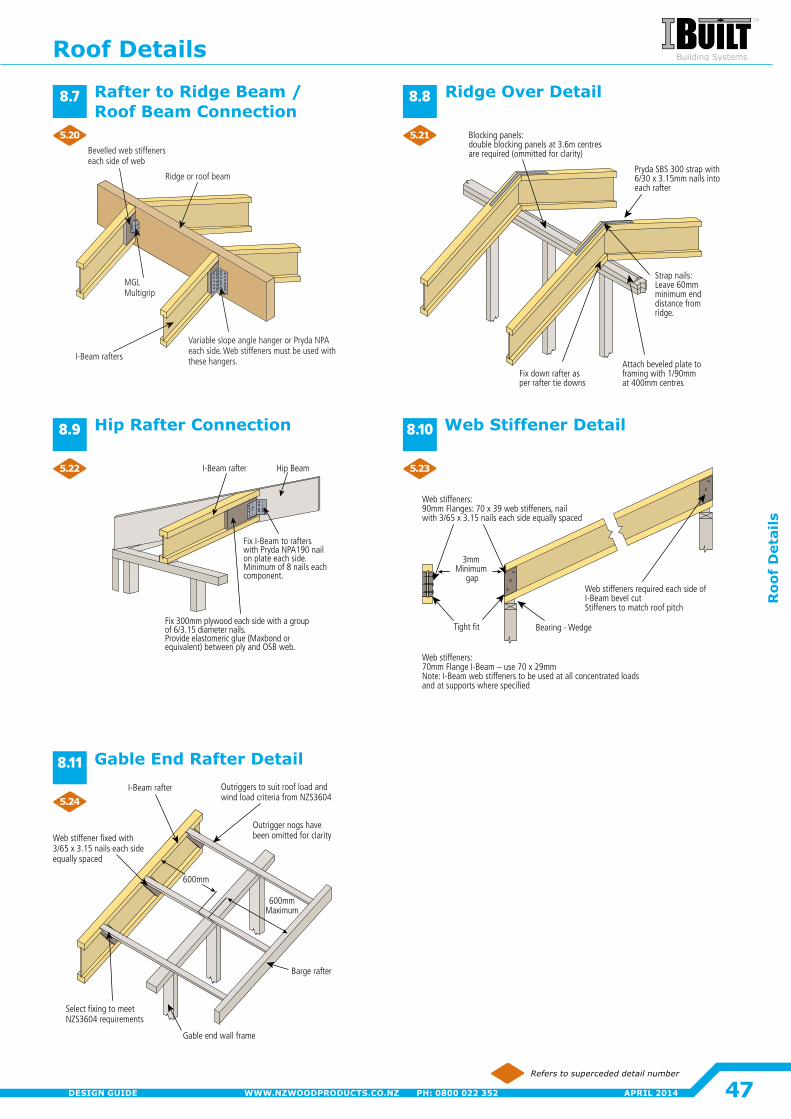
Blocking panels:double blocking panels at 3.6m centres are required (ommitted for clarity)
Fix down rafter as per rafter tie downs
Attach beveled plate to framing with 1/90mm at 400mm centres
Strap nails: Leave 60mm minimum end distance from ridge.
Pryda SBS 300 strap with 6/30 x 3.15mm nails into each rafter
I-Beam rafter
Web stiffener fixed with 3/65 x 3.15 nails each side equally spaced
Outriggers to suit roof load and wind load criteria from NZS3604
Barge rafter
Gable end wall frame
Select fixing to meet NZS3604 requirements
Outrigger nogs havebeen omitted for clarity
600mm
600mm Maximum
Variable slope angle hanger or Pryda NPA each side. Web stiffeners must be used with these hangers.
Ridge or roof beam
Bevelled web stiffeners each side of web
I-Beam rafters
MGL Multigrip
Tight fit
Web stiffeners:70mm Flange I-Beam – use 70 x 29mm Note: I-Beam web stiffeners to be used at all concentrated loads and at supports where specified
Web stiffeners required each side of I-Beam bevel cut Stiffeners to match roof pitch
Bearing - Wedge
Web stiffeners:90mm Flanges: 70 x 39 web stiffeners, nail with 3/65 x 3.15 nails each side equally spaced
3mm Minimum
gap
Hip BeamI-Beam rafter
Fix 300mm plywood each side with a groupof 6/3.15 diameter nails.Provide elastomeric glue (Maxbond or equivalent) between ply and OSB web.
Fix I-Beam to rafters with Pryda NPA190 nail on plate each side. Minimum of 8 nails each component.
Refers to superceded detail number
Ridge Over DetailRafter to Ridge Beam / Roof Beam Connection
Web Stiffener DetailHip Rafter Connection
Gable End Rafter Detail
8.7
8.9
8.11
8.8
8.10
5.20
5.22
5.24
5.21
5.23
Roof Details
47
Roo
f D
etai
ls
APRIL 2014WWW.NZWOODPRODUCTS.CO.NZ PH: 0800 022 352DESIGN GUIDE
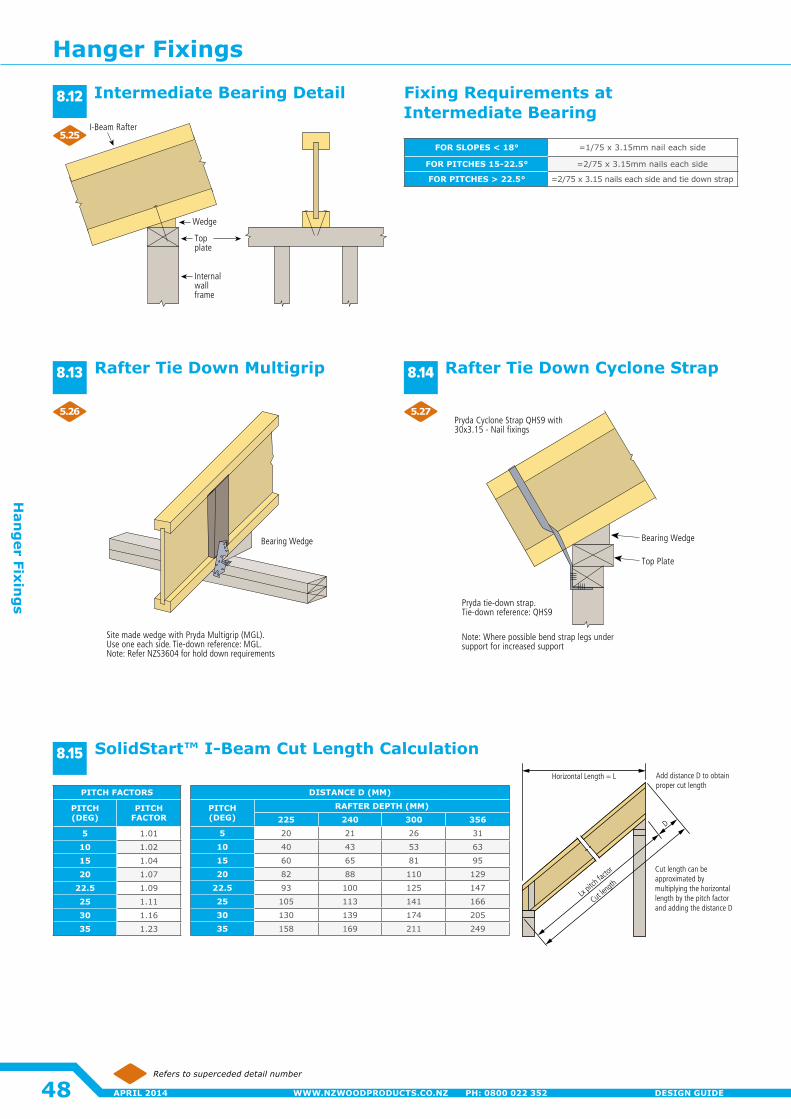
Bearing Wedge
Site made wedge with Pryda Multigrip (MGL).Use one each side. Tie-down reference: MGL.Note: Refer NZS3604 for hold down requirements
Pryda tie-down strap.Tie-down reference: QHS9
Note: Where possible bend strap legs under support for increased support
Pryda Cyclone Strap QHS9 with 30x3.15 - Nail fixings
Bearing Wedge
Top Plate
I-Beam Rafter
Wedge
Internal wall frame
Note: Refer table next page for fixing requirements
Top plate
FOR SLOPES < 18° =1/75 x 3.15mm nail each side
FOR PITCHES 15-22.5° =2/75 x 3.15mm nails each side
FOR PITCHES > 22.5° =2/75 x 3.15 nails each side and tie down strap
Fixing Requirements at Intermediate Bearing
Refers to superceded detail number
Rafter Tie Down Cyclone StrapRafter Tie Down Multigrip
SolidStart™ I-Beam Cut Length Calculation
8.13 8.14
8.15
Intermediate Bearing Detail8.12
DISTANCE D (MM)
PITCH (DEG)
RAFTER DEPTH (MM)225 240 300 356
5 20 21 26 31
10 40 43 53 63
15 60 65 81 95
20 82 88 110 129
22.5 93 100 125 147
25 105 113 141 166
30 130 139 174 205
35 158 169 211 249
PITCH FACTORS
PITCH (DEG)
PITCH FACTOR
5 1�01
10 1�02
15 1�04
20 1.07
22.5 1.09
25 1�11
30 1.16
35 1.23
Cut len
gthLx
pitch
factor
D
Add distance D to obtain proper cut length
Cut length can be approximated by multiplying the horizontal length by the pitch factor and adding the distance D
Horizontal Length = L
5.25
5.26 5.27
Hanger Fixings
48
Han
ger Fixin
gs
APRIL 2014 WWW.NZWOODPRODUCTS.CO.NZ PH: 0800 022 352 DESIGN GUIDE
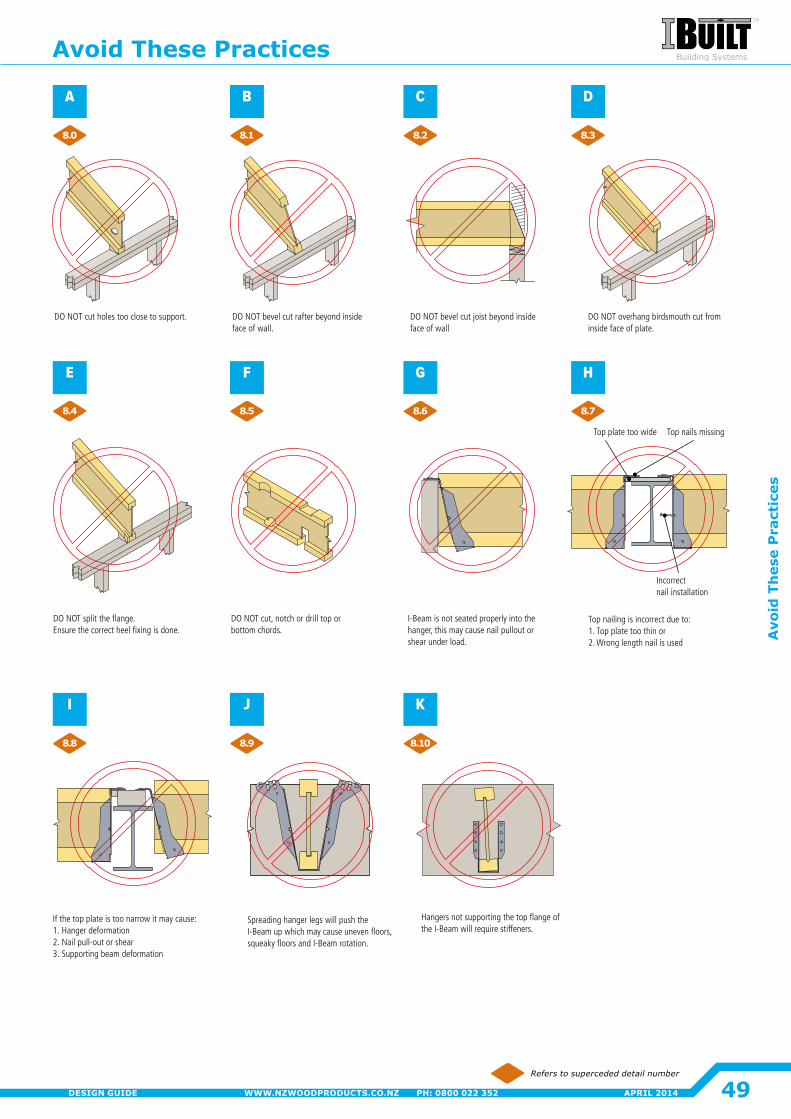
Spreading hanger legs will push the I-Beam up which may cause uneven floors, squeaky floors and I-Beam rotation.
If the top plate is too narrow it may cause: 1. Hanger deformation2. Nail pull-out or shear3. Supporting beam deformation
Hangers not supporting the top flange of the I-Beam will require stiffeners.
DO NOT bevel cut joist beyond inside face of wall
DO NOT cut holes too close to support. DO NOT bevel cut rafter beyond inside face of wall.
DO NOT overhang birdsmouth cut from inside face of plate.
DO NOT split the flange. Ensure the correct heel fixing is done.
DO NOT cut, notch or drill top or bottom chords.
Top plate too wide Top nails missing
Incorrect nail installation
Top nailing is incorrect due to:1. Top plate too thin or2. Wrong length nail is used
I-Beam is not seated properly into the hanger, this may cause nail pullout or shear under load.
Refers to superceded detail number
A
E
I
B
F
J
C
G
K
D
H
8.0
8.4
8.8
8.1
8.5
8.9
8.2
8.6
8.10
8.3
8.7
Avoid These Practices
49
Avo
id T
hes
e P
ract
ices
APRIL 2014WWW.NZWOODPRODUCTS.CO.NZ PH: 0800 022 352DESIGN GUIDE
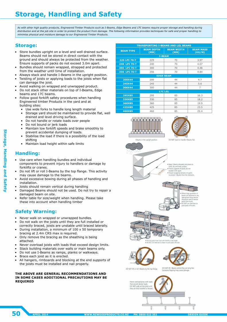
Storage, Handling and Safety
STORAGE• Store bundles upright on a level and well-drained surface.• Beams should not be stored in direct contact with the ground and should
always be protected from weather.• Ensure supports of packs do not exceed 3.0m apart.• Bundles should remain wrapped, strapped, and protected from the
weather until time of installation. • Always stack and handle I-beams in the upright position.• Twisting of joists or applying loads to the joist when fl at can damage
the joist.• Avoid walking on wrapped and unwrapped product.• Do not stack other materials on top of I-Beams, Edgebeams and 17C beams.• Follow good forklift safety procedures when handling Engineered Timber
Pro ducts in the yard and at building sites:• Use wide forks to handle long length material.• Storage yard should be maintained to provide fl at, well drained and level driving surface.• Do not handle or rotate loads over people.• Do not bounce or jerk loads.• Maintain low forklift speeds and brake smoothly to prevent accidentally dumping a load.• Stabilize the load if there is a possibility of the load shifting.• Maintain load height within safe limits.
HANDLING• Use care when handling bundles and individual components to prevent
injury to handlers or damage by forklifts or cranes.• Do not lift or roll Hyne I-Beams by the top fl ange. This activity may cause
damage to the Beams.• Avoid excessive bowing during all phases of handling and installation.• Joists should remain vertical during handing.• Damaged beams should not be used. Do not try to ‘repair’ a damaged
beam on site.• See table below for size/weight when handling. Please take these into
account when handling timber.
DO NOT lift I-Beams whilst they are lying flat. Excessive flapping may cause damage.
DO NOT lift or roll I-Beams by the top flange.
3.0m MAX.
• Keep I-Beams elevated and place on solid, dry and level surface.• Ensure supports of packs do not exceed 3.0m apart.• Ensure wrapping remains on packs to protect I-Beams from the elements.
• Remove packs from truck with forklift or side loader.• DO NOT use steel bars to lower or push packs off truck.
• Where large quantities of beams are delivered to site, appropriate lifting devices should be used to remove packs from trucks.• DO NOT use steel bars to push packs off trucks.
I-Beams in the upright position. DO NOT stack or handle I-Beams flat.
As with other high quality products, Engineered Timber Products such as I-Beams, Edgebeams and 17cs, require proper storage and handling during distribution and at the jobsite in order to protect the product from damage. The following information provides techniques for safe and proper handling to minimize physical and moisture damage to our Engineered Timber Products.
Beam Type Beam Depth Beam Width Beam Mass
I-Beam mm mm kg/m
200x70 200 70 4.0
245x70 245 70 4.3
300x70 300 70 4.7
Edgebeam
200x45 200 45 5.85
245x45 245 45 7.17
300x45 300 45 8.78
17C
295x85 295 85 16.30
330x85 330 85 18.23
360x85 360 85 19.89
425x85 425 85 23.48
460x85 460 85 25.42
525x85 525 85 29.01
Never overload joists with loads that exceed design loads. DO NOT walk on the joists until they are fully installed or braced.
SAFETY WARNING• Never walk on wrapped or unwrapped bundles.• Do not walk on the joists until they are fully installed or correctly braced,
joists are unstable until braced laterally.• During installation, a minimum of 100x50mm temporary bracing at 3.0m
centres maximum is required.• Only remove the bracing as the sheathing is being attached.• Never overload joists with loads that exceed design loads.• Stack building materials over walls or main beams only.• Do not use I-Beams as ramps, planks or walkways.• Brace each joint as it is erected• All hangers, rimboards and blocking at the end supports of the joists must
be installed and nail properly.THE ABOVE ARE GENERAL RECOMMENDATIONS AND IN SOME CASES ADDITIONAL PRECAUTIONS MAY BE REQUIRED.
Please Take Weight Of Beams Into Account When Transporting
9.0
14
3290 Construction Guide final 14 11/7/07 11:19:05 AM
TRANSPORTING I-BEAMS AND LGL BEAMS
BEAM TYPE BEAM DEPTH (MM)
BEAM WIDTH (MM)
BEAM MASS (KG/M)
I-BEAM225 LPI 70-T 225 70 3.97
240 LPI 70-T 240 70 4.07
300 LPI 70-T 300 70 4.48
356 LPI 70-T 356 70 4.84
EDGE BEAM200X44 200 44 4.7
245X44 245 44 5.6
300X44 300 44 7
17C LGL295X85 295 85 16.3
330X85 330 85 18.2
360X85 360 85 19.9
425X85 425 85 23.5
460X85 460 85 25.4
Aswithotherhighqualityproducts,EngineeredTimberProductssuchasI-Beams,EdgeBeamsand17Cbeamsrequireproperstorageandhandlingduringdistributionandatthejobsiteinordertoprotecttheproductfromdamage.ThefollowinginformationprovidestechniquesforsafeandproperhandlingtominimisephysicalandmoisturedamagetoourEngineeredTimberProducts.
Storage:• Store bundles upright on a level and well drained surface.
Beams should not be stored in direct contact with the ground and should always be protected from the weather.Ensure supports of packs do not exceed 3.0m apart.
• Bundles should remain wrapped, strapped and protected from the weather until time of installation�
• Always stack and handle I-Beams in the upright position.• Twisting of joists or applying loads to the joists when flat
can damage the joist.• Avoid walking on wrapped and unwrapped product.• Do not stack other materials on top of I-Beams, Edge
beams and 17C beams.• Follow good forklift safety procedures when handling
Engineered timber Products in the yard and at building sites:• Use wide forks to handle long length material• Storage yard should be maintained to provide flat, well
drained and level driving surface� • Do not handle or rotate loads over people• Do not bound or jerk loads• Maintain low forklift speeds and brake smoothly to
prevent accidental dumping of loads�• Stabilise the load if there is a possibility of the load
shifting• Maintain load height within safe limits
Handling:• Use care when handling bundles and individual
components to prevent injury to handlers or damage by forklifts or cranes.
• Do not lift or roll I-Beams by the top flange. This activity may cause damage to the beams.
• Avoid excessive bowing during all phases of handling and installation�
• Joists should remain vertical during handling• Damaged Beams should not be used. Do not try to repair a
damaged beam on site.• Refer table for size/weight when handling. Please take
these into account when handling timber
Safety Warning:• Never walk on wrapped or unwrapped bundles.• Do not walk on the joists until they are full installed or
correctly braced, joists are unstable until braced laterally.• During installation, a minimum of 100 x 50 temporary
bracing at 2.4m CRS max is required.• Only remove the bracing as the sheathing is being
attached�• Never overload joists with loads that exceed design limits.• Stack building materials over walls or main beams only.• Do not use I-Beams as ramps, planks or walkways.• Brace each joist as it is erected.• All hangers, rimboards and blocking at the end supports of
the joists must be installed and nail properly.
THE ABOVE ARE GENERAL RECOMMENDATIONS AND IN SOME CASES ADDITIONAL PRECAUTIONS MAY BE REQUIRED
Storage, Handling and Safety
50
Storag
e, Han
dlin
g an
d S
afety
APRIL 2014 WWW.NZWOODPRODUCTS.CO.NZ PH: 0800 022 352 DESIGN GUIDE
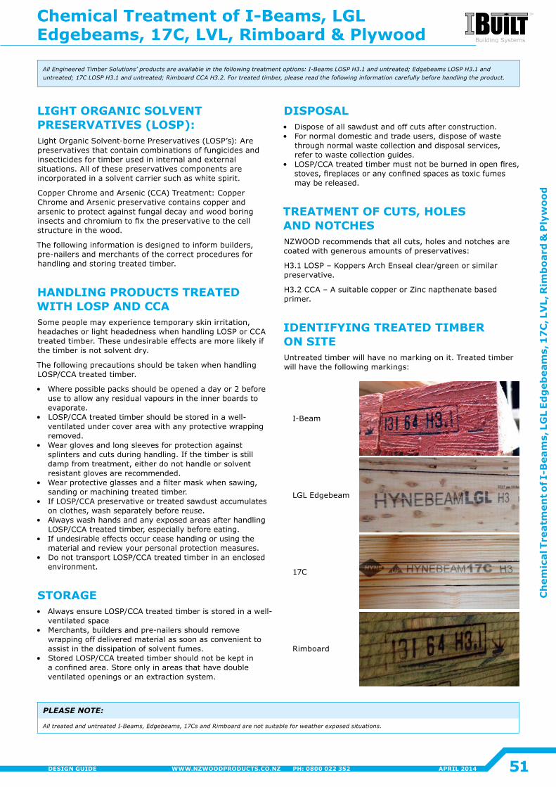
DISPOSAL• Dispose of all sawdust and off cuts after construction�• For normal domestic and trade users, dispose of waste
through normal waste collection and disposal services, refer to waste collection guides�
• LOSP/CCA treated timber must not be burned in open fires, stoves, fireplaces or any confined spaces as toxic fumes may be released.
TREATMENT OF CUTS, HOLES AND NOTCHESNZWOOD recommends that all cuts, holes and notches are coated with generous amounts of preservatives:
H3.1 LOSP – Koppers Arch Enseal clear/green or similar preservative�
H3.2 CCA – A suitable copper or Zinc napthenate based primer�
IDENTIFYING TREATED TIMBER ON SITEUntreated timber will have no marking on it. Treated timber will have the following markings:
I-Beam
LGL Edgebeam
17C
Rimboard
AllEngineeredTimberSolutions’productsareavailableinthefollowingtreatmentoptions:I-BeamsLOSPH3.1anduntreated;EdgebeamsLOSPH3.1anduntreated;17CLOSPH3.1anduntreated;RimboardCCAH3.2.Fortreatedtimber,pleasereadthefollowinginformationcarefullybeforehandlingtheproduct.
PLEASE NOTE:
AlltreatedanduntreatedI-Beams,Edgebeams,17CsandRimboardarenotsuitableforweatherexposedsituations.
LIGHT ORGANIC SOLVENT PRESERVATIVES (LOSP):Light Organic Solvent-borne Preservatives (LOSP’s): Are preservatives that contain combinations of fungicides and insecticides for timber used in internal and external situations� All of these preservatives components are incorporated in a solvent carrier such as white spirit�
Copper Chrome and Arsenic (CCA) Treatment: Copper Chrome and Arsenic preservative contains copper and arsenic to protect against fungal decay and wood boring insects and chromium to fix the preservative to the cell structure in the wood�
The following information is designed to inform builders, pre-nailers and merchants of the correct procedures for handling and storing treated timber.
HANDLING PRODUCTS TREATED WITH LOSP AND CCASome people may experience temporary skin irritation, headaches or light headedness when handling LOSP or CCA treated timber. These undesirable effects are more likely if the timber is not solvent dry.
The following precautions should be taken when handling LOSP/CCA treated timber.
• Where possible packs should be opened a day or 2 before use to allow any residual vapours in the inner boards to evaporate�
• LOSP/CCA treated timber should be stored in a well-ventilated under cover area with any protective wrapping removed�
• Wear gloves and long sleeves for protection against splinters and cuts during handling. If the timber is still damp from treatment, either do not handle or solvent resistant gloves are recommended�
• Wear protective glasses and a filter mask when sawing, sanding or machining treated timber.
• If LOSP/CCA preservative or treated sawdust accumulates on clothes, wash separately before reuse.
• Always wash hands and any exposed areas after handling LOSP/CCA treated timber, especially before eating.
• If undesirable effects occur cease handing or using the material and review your personal protection measures�
• Do not transport LOSP/CCA treated timber in an enclosed environment�
STORAGE• Always ensure LOSP/CCA treated timber is stored in a well-
ventilated space• Merchants, builders and pre-nailers should remove
wrapping off delivered material as soon as convenient to assist in the dissipation of solvent fumes�
• Stored LOSP/CCA treated timber should not be kept in a confined area. Store only in areas that have double ventilated openings or an extraction system.
Chemical Treatment of I-Beams, LGL Edgebeams, 17C, LVL, Rimboard & Plywood
51
Ch
emic
al T
reat
men
t of I
-Bea
ms,
LG
L Ed
geb
eam
s, 1
7C
, LV
L, R
imb
oard
& P
lyw
ood
APRIL 2014WWW.NZWOODPRODUCTS.CO.NZ PH: 0800 022 352DESIGN GUIDE
You are welcome to contact us for further information about the range of Engineered Timber Products, our Rimboard and Pryda fittings
Mailing Address: PO Box 13647 Onehunga Auckland 1643 New Zealand
Telephone: +64 9 276 7030 Fax: +64 9 270 0504
Customer Services Freephone: 0800 022 352 Freefax: 0800 022 357 Email: [email protected]
Technical Assistance: Freephone: 0800 022 352 Freefax: 0800 022 357 Email: [email protected]
Website: www�nzwoodproducts�co�nz