design and analysis of hydraulic jack for sugar mill setting · design and analyze the hydraulic...
TRANSCRIPT
International Research Journal of Engineering and Technology (IRJET) e-ISSN: 2395 -0056
Volume: 04 Issue: 05 | May -2017 www.irjet.net p-ISSN: 2395-0072
© 2017, IRJET | Impact Factor value: 5.181 | ISO 9001:2008 Certified Journal | Page 1632
Design and Analysis of Hydraulic Jack for Sugar Mill Setting
Rohit M. Chavan1, M. M. Mirza2, R. Biradar3
12Dept. of Mech. Engineering , Rajarambapu Institute of Technology, Sakharale, Islampur, India. 3Prodution Manager , Ulka Industries Pvt. Ltd. Pune, India.
--------------------------------------------------------------------------***-------------------------------------------------------------------------Abstract-The Vital Objective of Present Research is To Design and Analyze Hydraulic Jack for Sugar Mill Setting In Three Roller Sugar Mill. The Newly Design Jack System is Overcome the Demerits of Existing Mill Setting Arrangement. Present Paper Include The Component Design As Well As Analysis of Jack System. In This Case Solid Modeling of Required Vital Components are Done by Pro-e Software. The Component which are Going to Analyze are Ram and Ram Cylinder, Ram Cylinder and Plunger Cylinder. Here the theoretical Stress Calculation is carried Out for Each Component. Then the Static Structural Analysis is carried for Every Component with the Help of ANSYS Workbench 15. In this Analysis the Calculated Parameters are Von Misses Stresses (Equivalent Stresses) and Deformation. Finally here the Theoretical and Analytical Values are compared with Each Other for Validation Purpose.
Keywords- Three Roller Mill, Pro-e, ANSYS Workbench, Von Mises Stress, Pascal’s Principle
1. INTRODUCTION
Sugarcane is a grass of the genus Saccharum which is grown throughout tropical and subtropical regions, producing approximately 94 million tons of raw sugar worldwide. Factory processing of sugarcane begins with shredding and crushing of harvested cane stalks to extract the sucrose containing juice. The extraction of juice from prepared sugarcane is commonly performed using sets of counter rotating rolls. The rolling process is energy intensive and must obtain a high degree of liquid extraction without compromising the processing rate. Usually three roller mills are used for extraction of juice which consists of three rollers i.e. Top, Feed and Discharge rollers. Sugarcane is being fed into top and feed rollers which further passes through top and discharge roller along with trash plate. This trash plate is having a downside that 25% of total hydraulic load is shared by this trash plate in overcoming friction and remaining 75% only the useful one i.e. 25% hydraulic load is shared by feed roller and 50% is shared by discharge roller.
Crushing rolls are designed with high coefficient of friction and very low rotational (4–5 rpm) Speed. Considering above pitfalls two roller mills can be the best option because it doesn’t require trash plate, any trash plate adjustment and replacement. Two roller mills consist of only two rollers i.e. top and bottom roller.100% of hydraulic load is available for compression at bottom roller. Hydraulic load required is 70% of same size conventional 3-roller mill which is not shared and directly transferred to the bottom roller. 2- Roller has better drainage because of its
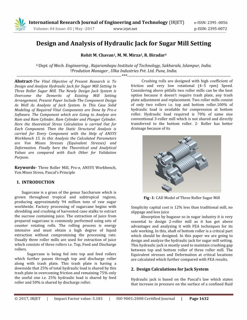
Fig -1: CAD Model of Three Roller Sugar Mill
Simplicity capital cost is 12% less than traditional mill, no slippage and less juice Absorption by bugasse so in sugar industry it is very essential to design 2-roller mill as it has got above advantages and analyzing it with FEA techniques for its safe working. In this, shaft of bottom roller is a critical part which should be designed. In this paper we are going to design and analyze the hydraulic jack for sugar mill setting. This hydraulic jack is mostly used to maintain crushing gap between top and bottom roller of three roller mill. The Equivalent stresses and Deformation at critical locations are calculated which further compared with FEA results.
2. Design Calculations for Jack System Hydraulic jack is based on the Pascal’s law which states that increase in pressure on the surface of a confined fluid
International Research Journal of Engineering and Technology (IRJET) e-ISSN: 2395 -0056
Volume: 04 Issue: 05 | May -2017 www.irjet.net p-ISSN: 2395-0072
© 2017, IRJET | Impact Factor value: 5.181 | ISO 9001:2008 Certified Journal | Page 1633
is transmitted undiminished throughout the confined vessel or system. According to Pascal Law, = FR×AP = FP×AR
- Force on Ram FR = Load × Gravity FR = 343350 N
2.1 Ram Design According to Design Catalogue for 35 Tone, Pressure is 27.97 Map
PR =
AR = 12275.65 mm2
2.2 Ram Diameter ( ) AR =
= 125 mm
According to hoop stresses Calculating Thickness of Cylinder ( ) FOS = 2
pd
t
= 29.13 = 60 mm Calculating Diameter of Ram Cylinder (DRC) = + 2 ×
= 190 mm
2.3 Calculating Height of Ram ( ) Height of Ram is Totally Depends on the Basis of Clearance between Bottom of Ram Cylinder and Bottom Surface of Ram, Assume, Clearance = 25 mm So Ram Height is, = 170 mm Height of Ram Cylinder ( ) = 190mm
2.4 Design of Plunger and Plunger Cylinder According To Design Catalogue Standard Value of Plunger Diameter is = 20 mm = 20 mm
=
= 314.15 mm2
2.5 Calculating Diameter of Plunger Cylinder ( )
pd
Approx tPC = 5 mm = + 2
= 30 mm
2.6 Plunger Displacement ( ) Plunger Displacement = Velocity Ratio =
=
= 40 = 40 mm Height of Plunger ( ) Plunger Height = Clearance + Plunger displacement = 80 mm Height of Plunger Cylinder ( ) =120 + Thickness = 130 mm 2.7 Design of Reservoir V = W×H×L
But We Filled Tank According To Design Consideration ⁄
th of Total Capacity - V= 10000 cm3 Oil in Tank = 10 liter
2.8 Design of Lever Length of Lever, Required Fulcrum Length = 40 mm Velocity Ratio = 11.25
=
=
Total Length = Velocity Ratio × Load Distance = 450 mm Without Extended Bar = 450 mm
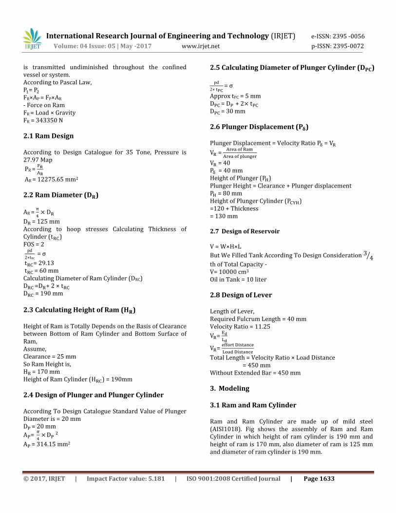
3. Modeling 3.1 Ram and Ram Cylinder Ram and Ram Cylinder are made up of mild steel (AISI1018). Fig shows the assembly of Ram and Ram Cylinder in which height of ram cylinder is 190 mm and height of ram is 170 mm, also diameter of ram is 125 mm and diameter of ram cylinder is 190 mm.
International Research Journal of Engineering and Technology (IRJET) e-ISSN: 2395 -0056
Volume: 04 Issue: 05 | May -2017 www.irjet.net p-ISSN: 2395-0072
© 2017, IRJET | Impact Factor value: 5.181 | ISO 9001:2008 Certified Journal | Page 1634
Fig -2: Assembly of Ram and Ram Cylinder
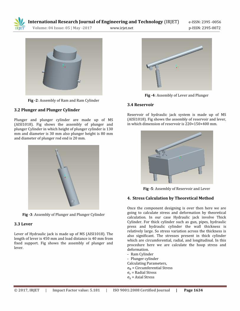
3.2 Plunger and Plunger Cylinder Plunger and plunger cylinder are made up of MS (AISI1018). Fig shows the assembly of plunger and plunger Cylinder in which height of plunger cylinder is 130 mm and diameter is 30 mm also plunger height is 80 mm and diameter of plunger rod end is 20 mm.
Fig -3: Assembly of Plunger and Plunger Cylinder
3.3 Lever
Lever of Hydraulic jack is made up of MS (AISI1018). The length of lever is 450 mm and load distance is 40 mm from fixed support. Fig shows the assembly of plunger and lever.
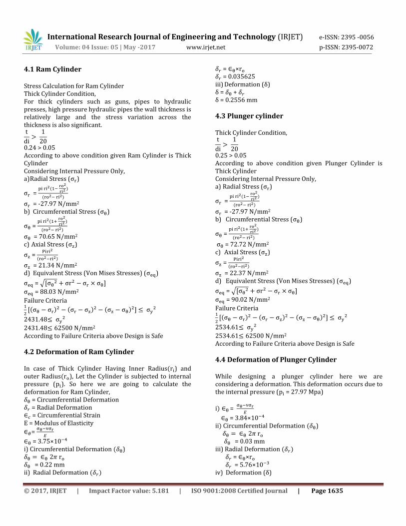
Fig -4: Assembly of Lever and Plunger
3.4 Reservoir
Reservoir of hydraulic jack system is made up of MS (AISI1018). Fig shows the assembly of reservoir and lever, in which dimension of reservoir is 220×150×400 mm.
Fig -5: Assembly of Reservoir and Lever
4. Stress Calculation by Theoretical Method Once the component designing is over then here we are going to calculate stress and deformation by theoretical calculation. In our case Hydraulic jack involve Thick Cylinder. For thick cylinder such as gun, pipes, hydraulic press and hydraulic cylinder the wall thickness is relatively large. So stress variation across the thickness is also significant. The stresses present in thick cylinder which are circumferential, radial, and longitudinal. In this procedure here we are calculate the hoop stress and deformation. - Ram Cylinder - Plunger cylinder Calculating Parameters, = Circumferential Stress = Radial Stress = Axial Stress
International Research Journal of Engineering and Technology (IRJET) e-ISSN: 2395 -0056
Volume: 04 Issue: 05 | May -2017 www.irjet.net p-ISSN: 2395-0072
© 2017, IRJET | Impact Factor value: 5.181 | ISO 9001:2008 Certified Journal | Page 1635
4.1 Ram Cylinder Stress Calculation for Ram Cylinder Thick Cylinder Condition, For thick cylinders such as guns, pipes to hydraulic presses, high pressure hydraulic pipes the wall thickness is relatively large and the stress variation across the thickness is also significant.
0.24 > 0.05 According to above condition given Ram Cylinder is Thick Cylinder Considering Internal Pressure Only, a) Radial Stress ( )
=
= -27.97 N/mm2 b) Circumferential Stress ( )
=
= 70.65 N/mm2 c) Axial Stress ( )
=
= 21.34 N/mm2 d) Equivalent Stress (Von Mises Stresses) ( )
= √ ]
= 88.03 N/mm2
Failure Criteria
]
2431.48
2431.48 N/mm2
According to Failure Criteria above Design is Safe
4.2 Deformation of Ram Cylinder In case of Thick Cylinder Having Inner Radius ) and outer Radius ), Let the Cylinder is subjected to internal pressure ( ). So here we are going to calculate the deformation for Ram Cylinder, = Circumferential Deformation = Radial Deformation = Circumferential Strain E = Modulus of Elasticity
=
= 3.75× i) Circumferential Deformation ) = 0.22 mm ii) Radial Deformation
= × = 0.035625 iii) Deformation (δ) δ + δ 0. 556 mm
4.3 Plunger cylinder
Thick Cylinder Condition,
0.25 > 0.05 According to above condition given Plunger Cylinder is Thick Cylinder Considering Internal Pressure Only, a) Radial Stress ( )
=
= -27.97 N/mm2 b) Circumferential Stress ( )
=
= 72.72 N/mm2
c) Axial Stress ( )
=
= 22.37 N/mm2 d) Equivalent Stress (Von Mises Stresses) ( )
= √ ]
= 90.02 N/mm2
Failure Criteria
]
2534.61
2534.61 N/mm2 According to Failure Criteria above Design is Safe
4.4 Deformation of Plunger Cylinder
While designing a plunger cylinder here we are considering a deformation. This deformation occurs due to the internal pressure ( = 27.97 Mpa)
=
= 3.84× Circumferential Deformation ) = 0.03 mm iii) Radial Deformation = × = 5.76× iv) Deformation (δ)
International Research Journal of Engineering and Technology (IRJET) e-ISSN: 2395 -0056
Volume: 04 Issue: 05 | May -2017 www.irjet.net p-ISSN: 2395-0072
© 2017, IRJET | Impact Factor value: 5.181 | ISO 9001:2008 Certified Journal | Page 1636
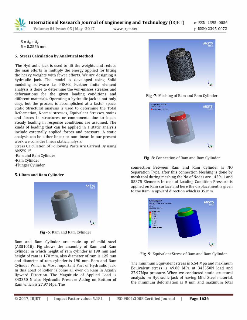
δ + δ 0. 556 mm 5. Stress Calculation by Analytical Method The Hydraulic jack is used to lift the weights and reduce the man efforts in multiply the energy applied for lifting the heavy weights with fewer efforts. We are designing a hydraulic jack. The model is developed using Solid modeling software i.e. PRO-E. Further finite element analysis is done to determine the von-misses stresses and deformations for the given loading conditions and different materials. Operating a hydraulic jack is not only easy, but the process is accomplished at a faster space. Static Structural analysis is used to determine the Total Deformation, Normal stresses, Equivalent Stresses, stains and forces in structures or components due to loads. Steady loading in response conditions are assumed. The kinds of loading that can be applied in a static analysis include externally applied forces and pressure. A static analysis can be either linear or non linear. In our present work we consider linear static analysis. Stress Calculation of Following Parts Are Carried By using ANSYS 15 -Ram and Ram Cylinder -Ram Cylinder -Plunger Cylinder
5.1 Ram and Ram Cylinder
Fig -6: Ram and Ram Cylinder
Ram and Ram Cylinder are made up of mild steel (AISI1018). Fig shows the assembly of Ram and Ram Cylinder in which height of ram cylinder is 190 mm and height of ram is 170 mm, also diameter of ram is 125 mm and diameter of ram cylinder is 190 mm. Ram and Ram Cylinder Which is Most Important Part of Hydraulic Jack. In this Load of Roller is come all over on Ram in Axially Upward Direction. The Magnitude of Applied Load is 343350 N also Hydraulic Pressure Acting on Bottom of Ram which is 27.97 Mpa. The
Fig -7: Meshing of Ram and Ram Cylinder
Fig -8: Connection of Ram and Ram Cylinder
connection Between Ram and Ram Cylinder is NO Separation Type, after this connection Meshing is done by mesh tool during meshing the No of Nodes are 142911 and 55875 Elements In case of Loading Condition Pressure is applied on Ram surface and here the displacement is given to the Ram in upward direction which is 35 mm.
Fig -9: Equivalent Stress of Ram and Ram Cylinder
The minimum Equivalent stress is 5.54 Mpa and maximum Equivalent stress is 49.80 MPa at 343350N load and 27.97Mpa pressure. When we conducted static structural analysis on Hydraulic jack of having Mild Steel material, the minimum deformation is 0 mm and maximum total
International Research Journal of Engineering and Technology (IRJET) e-ISSN: 2395 -0056
Volume: 04 Issue: 05 | May -2017 www.irjet.net p-ISSN: 2395-0072
© 2017, IRJET | Impact Factor value: 5.181 | ISO 9001:2008 Certified Journal | Page 1637
deformation is 0.0022 mm. at 343350N load and 27.97Mpa pressure.
Fig -10: Total Deformation of Ram and Ram Cylinder
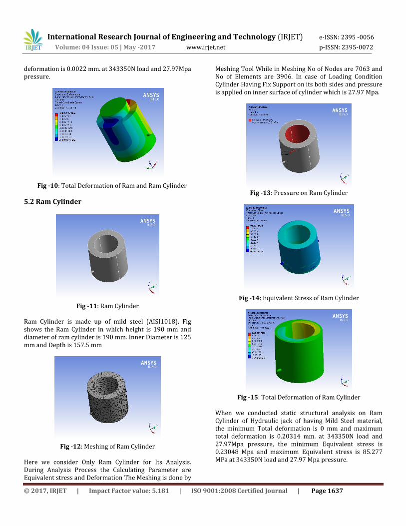
5.2 Ram Cylinder
Fig -11: Ram Cylinder
Ram Cylinder is made up of mild steel (AISI1018). Fig shows the Ram Cylinder in which height is 190 mm and diameter of ram cylinder is 190 mm. Inner Diameter is 125 mm and Depth is 157.5 mm
Fig -12: Meshing of Ram Cylinder
Here we consider Only Ram Cylinder for Its Analysis. During Analysis Process the Calculating Parameter are Equivalent stress and Deformation The Meshing is done by
Meshing Tool While in Meshing No of Nodes are 7063 and No of Elements are 3906. In case of Loading Condition Cylinder Having Fix Support on its both sides and pressure is applied on inner surface of cylinder which is 27.97 Mpa.
Fig -13: Pressure on Ram Cylinder
Fig -14: Equivalent Stress of Ram Cylinder
Fig -15: Total Deformation of Ram Cylinder
When we conducted static structural analysis on Ram Cylinder of Hydraulic jack of having Mild Steel material, the minimum Total deformation is 0 mm and maximum total deformation is 0.20314 mm. at 343350N load and 27.97Mpa pressure, the minimum Equivalent stress is 0.23048 Mpa and maximum Equivalent stress is 85.277 MPa at 343350N load and 27.97 Mpa pressure.
International Research Journal of Engineering and Technology (IRJET) e-ISSN: 2395 -0056
Volume: 04 Issue: 05 | May -2017 www.irjet.net p-ISSN: 2395-0072
© 2017, IRJET | Impact Factor value: 5.181 | ISO 9001:2008 Certified Journal | Page 1638
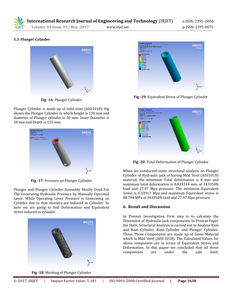
5.3 Plunger Cylinder
Fig -16: Plunger Cylinder
Plunger Cylinder is made up of mild steel (AISI1018). Fig shows the Plunger Cylinder in which height is 130 mm and diameter of Plunger cylinder is 30 mm. Inner Diameter is 20 mm and Depth is 125 mm.
Fig -17: Pressure on Plunger Cylinder
Plunger and Plunger Cylinder Assembly Mostly Used For The Generating Hydraulic Pressure by Manually Operated Lever. While Operating Lever Pressure is Generating on Cylinder due to that stresses are induced in Cylinder. So here we are going to find Deformation and Equivalent stress induced in cylinder.
Fig -18: Meshing of Plunger Cylinder
Fig -19: Equivalent Stress of Plunger Cylinder
Fig -20: Total Deformation of Plunger Cylinder
When we conducted static structural analysis on Plunger Cylinder of Hydraulic jack of having Mild Steel (AISI1018) material, the minimum Total deformation is 0 mm and maximum total deformation is 0.033314 mm. at 343350N load and 27.97 Mpa pressure. The minimum Equivalent stress is 0.33917 Mpa and maximum Equivalent stress is 88.784 MPa at 343350N load and 27.97 Mpa pressure.
6. Result and Discussion In Present Investigation First step is to calculate the Dimension of Hydraulic jack components. In Present Paper the Static Structural Analysis is carried out to Analyze Ram and Ram Cylinder, Ram Cylinder and Plunger Cylinder. These Three Components are made up of Same Material which Is Mild Steel (AISI 1018). The Calculated Values for above component are in terms of Equivalent Stress and Deformation. In this paper we concluded that all three components are under the safe limit.
International Research Journal of Engineering and Technology (IRJET) e-ISSN: 2395 -0056
Volume: 04 Issue: 05 | May -2017 www.irjet.net p-ISSN: 2395-0072
© 2017, IRJET | Impact Factor value: 5.181 | ISO 9001:2008 Certified Journal | Page 1639
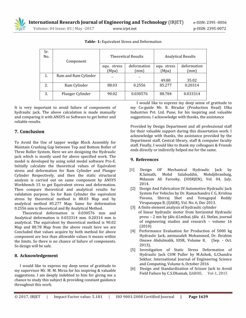
Table- 1: Equivalent Stress and Deformation
Sr. No.
Component
Theoretical Results
Analytical Results
equ. stress (Mpa)
deformation (mm)
equ. stress (Mpa)
deformation (mm)
1. Ram and Ram Cylinder _ _ 49.80
35.02
2. Ram Cylinder 88.03 0.2556 85.277 0.20314
3. Plunger Cylinder 90.02 0.030576 88.784 0.033314
It is very important to avoid failure of components of hydraulic jack. The above calculation is made manually and comparing it with ANSYS so Software to get better and reliable results.
7. Conclusion
To Avoid the Use of tapper wedge Block Assembly for Maintain Crushing Gap between Top and Bottom Roller of Three Roller System. Here we are designing the Hydraulic jack which is mostly used for above specified work. The model is developed by using solid model software Pro-E. Initially calculate the theoretical values of Equivalent stress and deformation for Ram Cylinder and Plunger Cylinder Respectively, and then the static structural analysis is carried out on same component by ANSYS Workbench 15 to get Equivalent stress and deformation. Then compare theoretical and analytical results for validation purpose. So for Ram Cylinder the equivalent stress by theoretical method is 88.03 Map and by analytical method 85.277 Map. Same for deformation 0.2556 mm is theoretical and By Analytical Method. Theoretical deformation is 0.030576 mm and Analytical deformation is 0.033314 mm. 0.20314 mm is analytical. The equivalent by theoretical method is 90.02 Map and 88.78 Map from the above result here we are Concluded that values acquire by both method for above component are less than allowable values it means within the limits. So there is no chance of failure of components. So design will be safe.
8. Acknowledgement I would like to express my deep sense of gratitude to my supervisor Mr. M. M. Mirza for his inspiring & valuable suggestions. I am deeply indebted to him for giving me a chance to study this subject & providing constant guidance throughout this work.
I would like to express my deep sense of gratitude to my Co-guide Mr. R. Biradar (Production Head) Ulka Industries Pvt. Ltd. Pune, for his inspiring and valuable suggestions. I acknowledge with thanks, the assistance Provided by Design Department and all professional staff for their valuable support during this dissertation work. I acknowledge with thanks, the assistance provided by the Department staff, Central library, staff & computer faculty staff. Finally, I would like to thank my colleagues & Friends ends directly or indirectly helped me for the same.
9. References
[1] Design OF Mechanical Hydraulic Jack by K.Sainath, Mohd Salahuddin, Mohdjibranbaig, Mdazam Ali Farooky, (IOSRJEN), Vol. 04, July. 2014.
[2] Design And Fabrication Of Automotive Hydraulic Jack System For Vehicles by Dr. Ramachandra C G, Krishna Pavana, Shivraj Shet and Venugopal Reddy Virupaxappa B, (IJAER), Vol. No. 6, Dec 2013.
[3] A finite element analysis of hydraulic cylinder of linear hydraulic motor from horizontal Hydraulic
press – 2 mn by ţălu d.l.mihai, ţălu d.l. Stefan, journal of engineering studies and research – volume 16 (2010)
[4] Performance Evaluation for Production of 5000 kg Hydraulic Jack, aminusaleh Mohammed, Dr. Ibrahim Onuwe Abdulmalik, IOSR, Volume 8, (Sep. - Oct. 2013),
[5] Investigation of Static Stress Deformation of Hydraulic Jack CUM Puller by M.Ashok, G.Chandra Sekhar, International Journal of Engineering Science and Computing, Volume 6, October 2016
[6] Design and Standardization of Scissor Jack to Avoid Field Failure by C.S.Dhamak, IJARIIE, Vol-1, 2015