design a smart control strategy to implement an intelligent
TRANSCRIPT

Research ArticleDesign a Smart Control Strategy to Implement an IntelligentEnergy Safety and Management System
Jing-Min Wang and Ming-Ta Yang
Department of Electrical Engineering, St. John’s University, No. 499, Section 4, Tam King Road, Tamsui District,New Taipei City 25135, Taiwan
Correspondence should be addressed to Ming-Ta Yang; [email protected]
Received 12 August 2014; Accepted 6 October 2014; Published 28 October 2014
Academic Editor: Kyung-Chang Lee
Copyright © 2014 J.-M. Wang and M.-T. Yang. This is an open access article distributed under the Creative Commons AttributionLicense, which permits unrestricted use, distribution, and reproduction in any medium, provided the original work is properlycited.
The energy saving and electricity safety are today a cause for increasing concern for homes and buildings. Integrating the radiofrequency identification (RFID) and ZigBee wireless sensor network (WSN)mature technologies, the paper designs a smart controlstrategy to implement an intelligent energy safety andmanagement system (IESMS)which performs energymeasuring, controlling,monitoring, and saving of the power outlet system. The presented RFID and billing module is used to identify user, activatesmart power outlet (SPO) module, deduct payable for electricity, and cut off power supply to the outlets by taking away the RFIDcard. Further work on the SPO module, a control strategy based on the minimum effect and first-in first-out rule, is designed toautonomously shut down some of the power outlets instantly to prevent electrical circuit overload. In addition, the WSN transfersthe power parameters of each SPO module to central energy monitoring platform, and the monitoring platform with graphicaluser interface (GUI) displays the real-time information and power charge of the electricity. Numerous tests validate the proposedIESMS and the effectiveness of the smart control strategy. The empirical findings may provide some valuable references for smarthomes or smart buildings.
1. Introduction
The world population is rapidly ageing. According to theWorld Health Organization (WHO) in 2012, the proportionof elderly population over 60 years old will double from about11% to 22% between 2000 and 2050. In addition, around 4%–6% of older people in developed countries have experiencedsome form of maltreatment at home. Creation an aged-friendly environment and safety living is today an attractiveissue. The smart home or smart building concept, of course,is a promising and cost-effective way to the problems. Thepopularity of home automation has been increasing greatly inrecent years due to much higher affordability and simplicitythrough network connectivity [1–5], but its current status isnot matured [1].
Fires in residences have taken a high toll of life andproperty. US Fire Administration indicated that there were362,100 residential building fires, 2,555 civilian fire deaths,13,275 civilian fire injuries, and around $6.6 billion inproperty damage in 2010. Overloaded electrical appliances,
frayed wires and extension cords, and blown fuses are themost common causes of house fires. A no fuse breaker (NFB)or called molded case circuit breaker (MCCB) is a plasticprotective device that interrupts a current if the currentexceeds the trip rating of the breaker. The NFB is installed inthe low voltage circuit to protect electrical equipment fromoverload and short circuit. On the overload trip operatingcharacteristics, even though the NFB trips, the operatingcircuit may be overheat already. In fact, over 80% electricalfires start below the safety threshold of NFB. NFB could notguarantee the energy safety. Additionally, long-term overloadof the NFB may cause aging mechanism, contact fault, ordelay trip which always results in electrical fires for the NFBfailure. Once the NFB trips; furthermore, it would cause themajor power outages or electricity blackouts that are verycostly for energy providers and very uncomfortable for users.How to reduce the region of power outage and prevent firesuffered from overload appliances is also the concern of thework.
Hindawi Publishing CorporationInternational Journal of Distributed Sensor NetworksVolume 2014, Article ID 312392, 10 pageshttp://dx.doi.org/10.1155/2014/312392

2 International Journal of Distributed Sensor Networks
Standby power is electricity used by appliances andequipment while they are switched off or not perform theirprimary functions. In 2007, International Energy Agency(IEA) pointed out that advanced country families did notpull the plug and wasted standby power, accounting for about5% to 10% of the total electricity consumption. The standbypower for every family was nearly 30 kWH monthly andresulted in carbondioxide (CO
2) emission of 16 kg.Moreover,
the standby power was responsible for roughly 1% of globalcarbon dioxide emissions. This is a serious threat for energycrisis and greenhouse effect. The utilization of renewableenergy resources [6] and the development of efficient energymanagement [7, 8] are the key solutions to these problems.
Power outlets or power sockets are probably the mostcommonly used electrical devices in modern home envi-ronments. Unlike conventional power outlets, smart poweroutlets could measure and monitor consumption electricityand control ON/OFF states of the electrical appliances. Thesmart power outlets have recently emerged as a newparadigmfor home energymanagement that can autonomously controlelectrical appliances and especially provide safety electricityenvironment. The needs of finding a smart and intelligentpower outlet are increasing concern [9].
Currently, consumption electricity is a rather complexissue for the end-user. The values of consumption electricityare hidden from the user. One is never aware which devicecontributes to it to which amount. Consequently, the visu-alization of power consumption data of electrical appliancesfor enhancing energy-awareness is becoming increasinglyimportant.
In recent years, the design of efficient energy man-agement system for homes or buildings is an active fieldof research. With the advance of microelectromechanicalsystem and wireless communication technology have led togreat progress in radio frequency identification (RFID) [10–13] and wireless sensor network (WSN) [5, 8, 13–15]. Amongthe various applications, energy management is probably themost important one to be addressed. Elzabadani et al. [16]presented an intelligent way to sense new devices installedin a smart space. As a result, it can identify and monitorany load, but it is unable to collect power information. Songet al. [17] constructed a ZigBee-based power outlet for smarthomes, but it did not measure power consumption. Abe et al.[18] proposed a ZigBee-based smart power outlet network forgathering power consumption data. However, the presentedenergy management system does not provide any protectionin an emergency. Based on the ZigBee communication andinfrared remote control, Han et al. [19] proposed a systemthat performed active control for reducing standby powerusing sensor information.The study lacks overload detectionand protection. Huang et al. [20] constructed a ZigBee-basedmonitoring system with self-protection. The work equippedeach power outlet with an energy metering IC to calculatepower parameters from the outlet. It created more complexcircuit structure and higher device costs. In addition, they justfocused on two outlets protection in a branch.
Energy management system is the integration of tech-nologies and services through home networking for an intel-ligent living environment. In view of the energy conservation
and energy safety trends, the paper presents a valuableapproach to this issue. The intelligent energy safety andmanagement system (IESMS) is proposed to lower CO
2
emissions and higher electricity safety by reducing end-user consumption electricity and preventing electrical circuitoverload. Compared to the existing related research [17–20],there are some key features concerned with the work.
(i) Using household appliances, the user needed to beidentified and obey user-pays principle by means ofthe RFID and billing module. The payment mecha-nism may motivate user to save energy.
(ii) Using the minimum effect and first-in first-out rule,a smart control strategy is designed to realize energy-aware coordination of the household appliances andto implement the IESMS. A microcontroller (MCU)programming is developed to secure four poweroutlets in an electrical loop from overload and ensurehome against fire.
(iii) The paper constructed a SPO module with only anenergy metering IC to measure and calculate powerconsumption of each of the four power outlets bya multiplexer. Compared with the literature [20],expenses were reduced. Moreover, the work devel-oped a smart control strategy to exercise control overthe four power outlets in an electrical loop.
(iv) To achieve further energy efficiency, all the poweroutlets would be automatically shut down while userwas taking away the RFID card. Consequently, thereis no standby power consumption of the householdappliances.
The results of the study may be useful to researchersattempting to develop smart homes or smart buildings. Fur-thermore, the IESMS can be applied to the service apartmentor dormitory.
The remainder of the paper is organized as follows: thesystem architecture and operation is explained in Section 2.Section 3 describes the functions of RFID and billingmodule.SPO module is developed and implemented in Section 4 indetail. Section 5 proposed a smart control strategy that per-forms overload detection and protection. Numerous exper-imental results are presented in Section 6. Finally, Section 7presents the conclusions for the work.
2. System Architecture and Operation
The capability of power controlling, monitoring, and energysafety is indispensable to power management. The sectionpresents the architecture for realizing the IESMS based onthe user-pays principle. Figure 1 depicts the applied IESMSfor a building. The RFID and billing module, SPO module,and ZigBee WSN transmission module were installed ineach room. The supervisor could access the electricity statusthrough the ZigBee WSN and by the graphic user interface(GUI), which is performed in central energy monitoringplatform. The IESMS operation is described as follows.

International Journal of Distributed Sensor Networks 3
Central energy monitoringplatform
Lobby coordinatorFloor routerRoom end device
Room 2
Room 1
Room 1
Room 1
Floor 1Floor 1
Floor 3
Floor 2
ZigBee WSN
Smart power outletRFID and billingmodule
Smart power outletRFID and billingmodule
Smart power outletRFID and billingmodule
Smart power outletRFID and billingmodule
...
...
...
RFID
RFID
RFID
RFID
Room N
Room N
Room N
Floor M
Floor M
Room N-1
Floor M-1
Floor M-2
Figure 1: Applied IESMS for a building.
First, the RFID and billing module could control useraccess and control on or off the power outlets. In addition,the module would complete the user-pays claim and shutdown power outlets automatically as user leaves the roomand takes away the RFID card. As a result the standby powerconsumption of the household appliances is saving.
Second, the SPO module is the critical module of thewhole system since power measurements and overload pro-tection are integrated within SPO. It is an autonomous lowvoltage overload control that can provide power systemoperation safety. The power outlet system comprises fourreceptacles each with voltage/current sensing and controlaction, energy metering IC for energy measurement, a 16-bitMCU for implementing safety operation, and ZigBee WSNmodule for transmitting the related data to central energymonitoring platform. The SPO module detected the powerparameters anytime while a household appliance plug wasput in the power outlet. Once the operating current of anelectrical loop was over the set threshold, the control unitwould shut down one or more of the power outlets based onthe minimum effect and first-in first-out rule. Accordingly,a major power outage would not happen in the designedsystem.
Third, the ZigBee is a WSN standard based on the IEEE802.15.4 and expected to have an explosive growth in remote
control and monitoring applications because of its low costand low power consumption. The work employed XBee-ProSeries 2 [21] that is designed for high power and long rangetransmission for the ZigBeeWSN.The work used cluster treenetwork structure to connect other ZigBee devices on thenetwork. The ZigBee end device was installed in each SPOmodule for transferring the power parameters to the centralenergymonitoring platform. Furthermore, the central energymonitoring platform has a lobby coordinator to collect all thedata fromfloor routers, which are repeaters set in the staircaseof each floor.
Finally, the central energy monitoring platform mainlyconsists of ZigBee lobby coordinator and displayer to accom-plish the remote energy monitoring. The coordinator isthe core of the whole ZigBee WSN, which is in chargeof producing web beacon, collecting all the informationgenerated by SPO module of each room, and coordinatingthe traffic of each floor router. All the collected informationis stored in SQL (structured query language) server. Themonitoring platform used visual basic (VB) as the interfacesoftware to provide a user-friendly environment.TheGUI onthe monitoring platform would display the real-time powerparameters and power charge for each power outlet in anelectrical loop. The operation flowchart of the system isillustrated in Figure 2.

4 International Journal of Distributed Sensor Networks
SPO module power outage
Confirm user via RFID
Identifyverification
Supply power to the SPO module
Activate the using household appliances
Collect power parameters from each power outlet and calculate charge
ZigBee WSN
Display the power parameters and charge on the central energy monitoring platform
Shut down some of the appliances
Yes
Yes
No
No
Total current> threshold
Figure 2: Operation flowchart of the IESMS.
3. RFID and Billing Module
RFID is composed of reader/writer and RFID tag. It is anautomatic wireless identification technology that uses radiowave to transmit data and uniquely identify users individuallyaccording to their unique identifiers recorded in each RFIDtag. The reader/writer is a device that receives signal backfrom the tag and writes data on the tag. If a user with RFIDcard enters a room, the RFID unit will recognize the user andthen AC power supplies to SPO module. By the billing unit,the electricity bill will be deducted from the RFID card.
The work used the RFID reader/writer module MifareRC522 [22] connected to Arduino Uno [23] to read/write thepassive tag. The Arduino Uno is a MCU board based on theATmega328. The RFID card was used to control user accessand security, control power outlets ON/OFF, and implementthe user-pays principle.
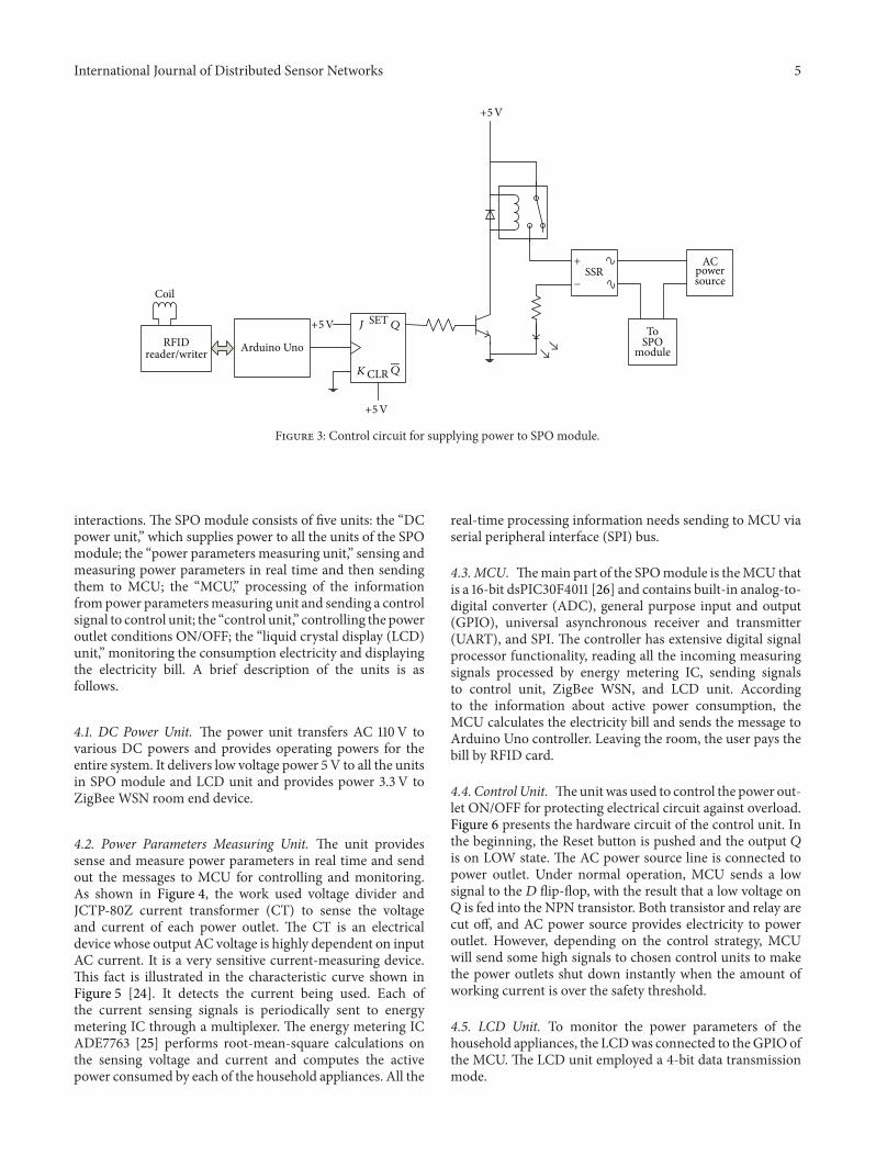
Figure 3 shows the control circuit withRFID andArduinoUno for supplying power to SPO module. The work usedsolid state relay (SSR) instead of traditional relay for reducingpower consumption. The RFID and Arduino module sends
a high voltage to the 𝐽-𝐾 flip-flop and then the flip-flopproduces a high voltage to drive the NPN power transistorwhile the user identification is confirmed.The contact of SSRcloses and the AC power source line is connected to SPOmodule. The SPO module is thus ready for work. A diodeis placed across the relay coil to protect it from arcing eachtime the coil is deenergized. Moreover, all the power outletswere shut down for the identification failure. The nature wayto reduce the standby power consumption of the householdappliances achieves further energy-saving.
4. SPO Module
The SPO module with an energy metering IC is designedto sense, measure, control, and monitor for each householdappliance and to provide a safety feature in the form ofoverload protection. The SPO module was developed on theassumption that an electrical circuit provided four poweroutlets to be used in a room. Figure 4 shows the detailedblock diagrams of the SPO module indicated units and their
International Journal of Distributed Sensor Networks 5
Coil
RFIDreader/writer Arduino Uno
+5V
+5V
+5V
J SET Q
KCLR Q
SSR
ToSPO
module
ACpowersource
+
−
Figure 3: Control circuit for supplying power to SPO module.
interactions. The SPO module consists of five units: the “DCpower unit,” which supplies power to all the units of the SPOmodule; the “power parameters measuring unit,” sensing andmeasuring power parameters in real time and then sendingthem to MCU; the “MCU,” processing of the informationfrompower parametersmeasuring unit and sending a controlsignal to control unit; the “control unit,” controlling the poweroutlet conditions ON/OFF; the “liquid crystal display (LCD)unit,” monitoring the consumption electricity and displayingthe electricity bill. A brief description of the units is asfollows.
4.1. DC Power Unit. The power unit transfers AC 110V tovarious DC powers and provides operating powers for theentire system. It delivers low voltage power 5V to all the unitsin SPO module and LCD unit and provides power 3.3 V toZigBee WSN room end device.
4.2. Power Parameters Measuring Unit. The unit providessense and measure power parameters in real time and sendout the messages to MCU for controlling and monitoring.As shown in Figure 4, the work used voltage divider andJCTP-80Z current transformer (CT) to sense the voltageand current of each power outlet. The CT is an electricaldevice whose output AC voltage is highly dependent on inputAC current. It is a very sensitive current-measuring device.This fact is illustrated in the characteristic curve shown inFigure 5 [24]. It detects the current being used. Each ofthe current sensing signals is periodically sent to energymetering IC through a multiplexer. The energy metering ICADE7763 [25] performs root-mean-square calculations onthe sensing voltage and current and computes the activepower consumed by each of the household appliances. All the
real-time processing information needs sending to MCU viaserial peripheral interface (SPI) bus.
4.3.MCU. Themain part of the SPOmodule is theMCU thatis a 16-bit dsPIC30F4011 [26] and contains built-in analog-to-digital converter (ADC), general purpose input and output(GPIO), universal asynchronous receiver and transmitter(UART), and SPI. The controller has extensive digital signalprocessor functionality, reading all the incoming measuringsignals processed by energy metering IC, sending signalsto control unit, ZigBee WSN, and LCD unit. Accordingto the information about active power consumption, theMCU calculates the electricity bill and sends the message toArduino Uno controller. Leaving the room, the user pays thebill by RFID card.
4.4. Control Unit. Theunit was used to control the power out-let ON/OFF for protecting electrical circuit against overload.Figure 6 presents the hardware circuit of the control unit. Inthe beginning, the Reset button is pushed and the output 𝑄is on LOW state. The AC power source line is connected topower outlet. Under normal operation, MCU sends a lowsignal to the 𝐷 flip-flop, with the result that a low voltage on𝑄 is fed into the NPN transistor. Both transistor and relay arecut off, and AC power source provides electricity to poweroutlet. However, depending on the control strategy, MCUwill send some high signals to chosen control units to makethe power outlets shut down instantly when the amount ofworking current is over the safety threshold.
4.5. LCD Unit. To monitor the power parameters of thehousehold appliances, the LCDwas connected to theGPIO ofthe MCU. The LCD unit employed a 4-bit data transmissionmode.

6 International Journal of Distributed Sensor Networks
DC power
unit
LCD unitZigBee WSN
room end device
To Arduino Uno
microcontroller
MCU
SPI
GPIO
Current sensing Current sensing Current sensing Current sensing
Energy metering IC
Differential
Voltage sensing circuit
From MCU GPIO
From MCU GPIO
From MCU GPIO
From MCU GPIO
From MCU GPIO
To differential To
controller unit
Binary control input
binary control input
Power parameters measuring unit
To entire system
AC power sourcecontrolled by
RFID unit
Control unit 1 Control unit 2 Control unit 3 Control unit 4
circuit 1 circuit 2 circuit 3 circuit 4
4-channel multiplexer
4-channel multiplexer
UART(TX)
Outlet 1 Outlet 2 Outlet 3 Outlet 4
1, 2, 3, and 4
Figure 4: Detailed block diagrams of the SPO module.
0.01 0.1 1 10 100 10000.001
0.01
0.1
1
10Ta = 25∘C
Sensed current in Amps RMS (IO)
100Ohms
10Ohms
Out
put i
n Vo
lts R
MS
(V)
Figure 5: Voltage-current characteristic curve of the JCTP-80Z.
5. Smart Control Strategy
A smart control strategy needs to be developed and pro-grammed to become aware of any overload and to sendout some signals to control units for controlling poweroutlets ON/OFF. The section presents the control algorithmto prevent circuit overload.
+5V
+5VFromMCUGPIO
Reset
Outlet
D SETQ
CLR Q
AC power
controlled byRFID unit
source
Figure 6: Control power outlet ON/OFF.
5.1. Safety Threshold Current for Overload Protection. TheMCU dsPIC30F4011 has a built-in 10-bit high-speed ADCwith four sample/hold devices and 500 ksps conversion rate.The maximum analog voltage is 5 V, then 1V analog inputcan be converted to the digital value of [(210− 1)/5 V] ×1 V = 204.6. By looking at the characteristic curve for CT(please refer to Figure 5), an AC 9A current produces AC 1V

International Journal of Distributed Sensor Networks 7
voltage with 100Ω load. For the power line in an electricalloop was set by threshold current of 16A in this work, thecorresponding digital value was (16A/9A) × 204.6 = 363.73.The allowable digital value of 364 was thus chosen as thesafetymargin of the total consumption current for the studiedSPO module. The safety threshold can be adjusted based onthe rating current of the electrical loop.
5.2. Working Flowchart. The focus of our research was topropose a control strategy for the SPO module that was ableto detect the total working current of the four householdappliances with safety operation and overload protection inan electrical loop. The flow diagram of the control strategyin Figure 7 was used to show the sequence of the programexecution, in which 𝑂
𝑖is the transformed digital value for
the 𝑖th power outlet current. As mentioned earlier, the valueof the Base with acceptable margin was set 364. The pro-gramming flowwas based on theminimum effect and first-infirst-out rule. The priority of the control strategy is that thenumber of shut power outlets is a minimum and the poweroutlets are shut down sequentially when overload occurs. Forexample, four household appliances labeled as A, B, C, andD are plugged in power outlets sequentially. The shutdownorder of the power outlets is as follows:A → B → C → D →A + B → A + C → A + D → B + C → B +D → C +D → A + B +C → A + B +D → B +C +D → A +B + C + D.
6. Experimental Results and Validation
A prototype demo system with four power outlets wasbuilt in an electrical loop. Figure 8 shows the SPO moduleprototype for measuring, controlling, and monitoring ofpower outlets in a room. As mentioned in the precedingsection, the total current consumed by household applianceswith safety margin was set 16A. The MCU controls thepower outlets ON/OFF by using the minimum effect andfirst-in first-out rule. To verify the feasibility of the controlstrategy and to illustrate the reliability of the proposed SPO,numerous experiment measurements and tests were made inthe section.
The list of the selected household appliances for thetest is shown in Table 1. At first the user was needed to beidentified via RFID unit. The electrical loop with four poweroutlets provided electricity for household appliances. Of thevarious tests evaluated, the experiments were executed onthe assumption that the appliances were requested to plugin the power outlets from 1 to 4 in order. Table 2 shows theresults with promising outcome. The cross “X” on the tableis a symbol of unused power outlet. From Table 2, it wasdemonstrated to make sure that the proposed SPO moduleworked well, with regard to both hardware (modules of RFIDand SPO) and software (execution of programs). Comparedwith the existing conventional power outlet, the designedpower outlet made every home a smarter, safer and moreenergy efficient environment for consumers and families.
By the ZigBee WSN transmission, Figure 9 shows theGUI monitoring platform, in which it displays the real-time
Table 1: Household appliances to be tested in the work.
Item codes Household appliancesOperating current(monitored by
LCD)𝐴 Electric fan 0.41 A𝐵 Dehumidifier 1.89A𝐶 Electric pot 6.22A𝐷 Electric kettle 7.29A𝐸 Hair dryer 9.29A𝐹 Induction cooker 10.45A
results of Test 1 and the use of household appliances 𝐴 +𝐵 + 𝐶 + 𝐷. The monitor screen includes five blocks. Block𝐴 is the selected of the floor and room. Block 𝐵 displays thetotal working current together with the electrical energy andelectricity payment (NT dollar-domination) for the selectedroom. Block 𝐶 shows the values of the voltage, current andactive power of the four working power outlets collectedfrom the room end device. In addition, Block 𝐷 is used toshow the current real-time dynamic waveforms of the voltage(upper with red color) and current (lower with green color)for the four appliances. Finally, the history information forthe working voltage, working current, and active power canbe also displayed in Block𝐷 by keying in the date on Block 𝐸.And the dynamic waveforms of the voltage and current willbe displayed in 24-hour time span.The display results of GUIshow the feasibility of the presented technology. Importantly,the proposed technology is designed for smart homes orsmart buildings.
7. Conclusion
Thedesign of an intelligent electricity environment is becom-ing more important because of the concerns for the lifeand property. In the paper, an IESMS is developed forachieving effective energy management and electricity safetyfor buildings. By integrating the matured RFID and ZigBeeWSN technologies, the paper proposes a smart controlstrategy and implements the IESMS. The control strategyexecuted in a microprocessor is designed to realize energy-aware coordination of the household appliances and toimplement the IESMS. The primary module in the work isthe SPOmodule.Themodule constantly measures the powerparameters and exercise control over the power outlets in anelectrical loop. Furthermore, it also ensures that the overloadcaused no damage to the infrastructure and does not triggerthe circuit breaker. Finally, numerous experiment tests havebeen conducted to validate the effectiveness and feasibilityof the proposed IESMS. The presented technology may beapplied to the service apartments. The paper is expected tocontribute the valuable results to the related researchers.

8 International Journal of Distributed Sensor Networks
Initialization
Base = 364
Detect currentsfor all outlets Oi
Sum = ΣOi Sum > Base i = 1 Sumi > Base Shut downoutlet Oi
i = 1 i ≦ 4 i = i + 1
j = i + 1
Sumij > Base Shut down
j ≦ 4 j = j + 1
i = 1 i ≦ 3 i = i + 1
j = i + 1 k = j + 1Shut down outletsOi, Oj and Ok
k = k + 1
k ≦ 4
j ≦ 3 j = j + 1
i = i + 1 i ≦ 2Shut down
all the outlets
outlets Oi and Oj
Yes
No Yes
No
Yes
No
Yes
No
Yes
No
Yes
No
Yes
No
Yes
Yes
No
No
Yes
No
i = 1, 2, 3, 4
Sumi = Sum − Oi
Sumij = Sumi − Oj
Sumijk = Sumij − Ok Sumijk > Base
Figure 7: Flow diagram of the program execution for the control strategy.

International Journal of Distributed Sensor Networks 9
Table 2: Experimental tests and results.
Experimental tests Household appliances Total current (A) Power outlet conditionsDemand Actuality Outlet 1 Outlet 2 Outlet 3 Outlet 4
Test 1
𝐴 0.41 0.41 ON X X X𝐴 + 𝐵 2.30 2.30 ON ON X X𝐴 + 𝐵 + 𝐶 8.52 8.52 ON ON ON X𝐴 + 𝐵 + 𝐶 + 𝐷 15.81 15.81 ON ON ON ON
Test 2
𝐸 9.29 9.29 ON X X X𝐸 + 𝐷 16.58 7.29 OFF ON X X𝐸 + 𝐷 + 𝐶 22.80 13.51 OFF ON ON X𝐸 + 𝐷 + 𝐶 + 𝐵 24.69 15.40 OFF ON ON ON
Test 3
𝐶 6.22 6.22 ON X X X𝐶 + 𝐹 16.67 10.45 OFF ON X X𝐶 + 𝐹 + 𝐸 25.96 15.51 ON OFF ON X𝐶 + 𝐹 + 𝐸 + 𝐵 27.85 12.34 OFF OFF ON ON
Test 4
𝐶 + 𝐸 15.51 15.51 ON ON X X𝐶 + 𝐸 + 𝐹 25.96 15.51 ON ON OFF X𝐶 + 𝐸 + 𝐹 + 𝐴 26.37 15.92 ON ON OFF ON𝐶 + 𝐸 + 𝐹 + 𝐷 33.25 13.51 ON OFF OFF ON
Figure 8: SPO module prototype.
Figure 9: Test results shown on GUI monitoring platform.
Conflict of Interests
The authors declare that there is no conflict of interestsregarding the publication of this paper.
References
[1] N. Saito, “Ecological home network: an overview,” Proceedingsof the IEEE, vol. 101, no. 11, pp. 2428–2435, 2013.
[2] T. A. Nguyen andM. Aiello, “Energy intelligent buildings basedon user activity: a survey,” Energy and Buildings, vol. 56, no. 1,pp. 244–257, 2013.
[3] M.-T. Yang, C.-C. Chen, and Y.-L. Kuo, “Implementation ofintelligent air conditioner for fine agriculture,” Energy andBuildings, vol. 60, pp. 364–371, 2013.
[4] T. Li, J. Ren, and X. Tang, “Secure wireless monitoring andcontrol systems for smart grid and smart home,” IEEE WirelessCommunications, vol. 19, no. 3, pp. 66–73, 2012.
[5] J. Byun, B. Jeon, J. Noh, Y. Kim, and S. Park, “An intelligentself-adjusting sensor for smart home services based on ZigBeecommunications,” IEEE Transactions on Consumer Electronics,vol. 58, no. 3, pp. 794–802, 2012.
[6] J.-M. Wang and C.-L. Lu, “Design and implementation of a suntrackerwith a dual-axis singlemotor for an optical sensor-basedphotovoltaic system,” Sensors (Switzerland), vol. 13, no. 3, pp.3157–3168, 2013.
[7] L. Zhao, J. L. Zhang, and R. B. Liang, “Development of anenergy monitoring system for large public buildings,” Energyand Buildings, vol. 66, pp. 41–48, 2013.
[8] D.-M. Han and J.-H. Lim, “Smart home energy managementsystem using IEEE 802.15.4 and zigbee,” IEEE Transactions onConsumer Electronics, vol. 56, no. 3, pp. 1403–1410, 2010.
[9] Y. Hiranaka, Y. Sato, T. Taketa, and S. Miura, “Smart poweroutlets with cross-layer communication,” in Proceedings of the13th International Conference on Advanced CommunicationTechnology (ICACT ’11), pp. 1388–1393, Phoenix Park, TheRepublic of Korea, February 2011.
[10] N. F. B. I. Gulcharan, H. Daud, N. M. Nor, T. Ibrahim, and E. T.Nyamasvisva, “Limitation and solution for healthcare networkusing RFID technology: a review,” Procedia Technology, vol. 11,pp. 565–571, 2013.

10 International Journal of Distributed Sensor Networks
[11] T. Nozawa and M. Inoue, “Smart Outlet for realizing secureand green living,” in Proceedings of the 15th IEEE InternationalSymposium on Consumer Electronics (ISCE ’11), pp. 432–437,Singapore, June 2011.
[12] T. Noma and Y. Ookuma, “Power and safety managem ent ofelectrical appliances in a smart power distribution system,” inProceedings of the IEEE International Conference on ConsumerElectronics (ICCE ’11), pp. 511–512, Las Vegas, Nev, USA, January2011.
[13] A. Heller and C. Orthmann, “Wireless technologies for the con-struction sector—requirements, energy and cost efficiencies,”Energy and Buildings, vol. 73, no. 4, pp. 212–216, 2014.
[14] G. P. Joshi, S. Acharya, C.-S. Kim,C.-S. Kim, B.-S. Kim, and S.W.Kim, “Smart solutions in elderly care facilities withRFID systemand its integration with wireless sensor networks,” InternationalJournal of Distributed Sensor Networks, vol. 2014, Article ID713946, 11 pages, 2014.
[15] K.-H. Chao and P.-Y. Chen, “An intelligent traffic flow controlsystem based on radio frequency identification and wirelesssensor networks,” International Journal of Distributed SensorNetworks, vol. 2014, Article ID 694545, 10 pages, 2014.
[16] A. Elzabadani, A. Helal, B. Abdulrazak, and E. Jansen, “Self-sensing spaces: smart plugs for smart environments,” in Pro-ceedings of the 3rd International Conference on Smart Nomes andHealth Telematics, pp. 91–98, Magog, Canada, July 2005.
[17] G. Song, F. Ding, W. Zhang, and A. Song, “A wireless poweroutlet system for smart homes,” IEEE Transactions on ConsumerElectronics, vol. 54, no. 4, pp. 1688–1691, 2008.
[18] K. Abe, H. Mineno, and T. Mizuno, “Development and eval-uation of smart tap type Home Energy Management Systemusing sensor networks,” in Proceedings of the IEEE ConsumerCommunications and Networking Conference (CCNC ’11), pp.1050–1054, Las Vegas, Nev, USA, January 2011.
[19] J. Han, C.-S. Choi, and I. Lee, “More efficient home energymanagement system based on ZigBee communication andinfrared remote controls,” IEEE Transactions on ConsumerElectronics, vol. 57, no. 1, pp. 85–89, 2011.
[20] L.-C. Huang, H.-C. Chang, C.-C. Chen, and C.-C. Kuo, “AZigBee-based monitoring and protection system for buildingelectrical safety,” Energy and Buildings, vol. 43, no. 6, pp. 1418–1426, 2011.
[21] “XBee-Pro Series 2 user manual,” http://www.adafruit.com/datasheets/XBee%20ZB%20User%20Manual.pdf.
[22] “RFID reader/writer module Mifare RC522 user manual,”http://www.nxp.com/documents/data sheet/MFRC522.pdf.
[23] Arduino Uno user manual, 2014, http://docs-asia.electrocom-ponents.com/webdocs/0e8b/0900766b80e8ba21.pdf.
[24] AC current transformer, June 2014, http://us.100y.com.tw/pdffile/46-J&D-JCTP-80,80Z.pdf.
[25] “Energy metering IC ADE7763 user manual,” http://www.analog.com/static/imported-files/data sheets/ADE7763.pdf.
[26] dsPIC30F4011 microcontroller user manual, 2014, http://ww1microchip.com/downloads/en/devicedoc/70135C.pdf.

Submit your manuscripts athttp://www.hindawi.com
VLSI Design
Hindawi Publishing Corporationhttp://www.hindawi.com Volume 2014
International Journal of
RotatingMachinery
Hindawi Publishing Corporationhttp://www.hindawi.com Volume 2014
Hindawi Publishing Corporation http://www.hindawi.com
Journal ofEngineeringVolume 2014
Hindawi Publishing Corporationhttp://www.hindawi.com Volume 2014
Shock and Vibration
Hindawi Publishing Corporationhttp://www.hindawi.com Volume 2014
Mechanical Engineering
Advances in
Hindawi Publishing Corporationhttp://www.hindawi.com Volume 2014
Civil EngineeringAdvances in
Acoustics and VibrationAdvances in
Hindawi Publishing Corporationhttp://www.hindawi.com Volume 2014
Hindawi Publishing Corporationhttp://www.hindawi.com Volume 2014
Electrical and Computer Engineering
Journal of
Hindawi Publishing Corporationhttp://www.hindawi.com Volume 2014
Distributed Sensor Networks
International Journal of
The Scientific World JournalHindawi Publishing Corporation http://www.hindawi.com Volume 2014
SensorsJournal of
Hindawi Publishing Corporationhttp://www.hindawi.com Volume 2014
Modelling & Simulation in EngineeringHindawi Publishing Corporation http://www.hindawi.com Volume 2014
Hindawi Publishing Corporationhttp://www.hindawi.com Volume 2014
Active and Passive Electronic Components
Hindawi Publishing Corporationhttp://www.hindawi.com Volume 2014
Chemical EngineeringInternational Journal of
Control Scienceand Engineering
Journal of
Hindawi Publishing Corporationhttp://www.hindawi.com Volume 2014
Antennas andPropagation
International Journal of
Hindawi Publishing Corporationhttp://www.hindawi.com Volume 2014
Hindawi Publishing Corporationhttp://www.hindawi.com Volume 2014
Navigation and Observation
International Journal of
Advances inOptoElectronics
Hindawi Publishing Corporation http://www.hindawi.com
Volume 2014
RoboticsJournal of
Hindawi Publishing Corporationhttp://www.hindawi.com Volume 2014