derivation of the kinetic energy equations ... - davis … · davis associates, inc. 43 ... the...
TRANSCRIPT

Derivation of the Kinetic Energy Equations
used by the
Revolving Door Energy Calculator (RDEC) Program
Warren F. Davis, Ph.D.Davis Associates, Inc.
43 Holden RoadNewton, MA 02465-1909
U.S.A.
December 15, 2010
www.davis-inc.comCopyright © 2010 by Davis Associates, Inc.

2
CONTENTS
Introduction . . . . . . . . . . . . . . . . . . . . . . . . . . . . . . . . . . . . . . . . . . . . . . . . . . . . . . . . . . . . . 3
Assumptions . . . . . . . . . . . . . . . . . . . . . . . . . . . . . . . . . . . . . . . . . . . . . . . . . . . . . . . . . 4Basic Kinetic Energy Equations . . . . . . . . . . . . . . . . . . . . . . . . . . . . . . . . . . . . . . . . . 5
Kinetic Energy Equations of Basic 3-wing and 4-wing Doors . . . . . . . . . . . . . . . . . . . 7
3-wing and 4-wing Doors without a Core . . . . . . . . . . . . . . . . . . . . . . . . . . . . . . . . 7Kinetic Energy Equations for a 3-wing Door without a Core . . . . . . . . . . . . . 9Kinetic Energy Equations for a 4-wing Door without a Core . . . . . . . . . . . . . 9
3-wing and 4-wing Doors with a Core . . . . . . . . . . . . . . . . . . . . . . . . . . . . . . . . . . 10Kinetic Energy Equations for a 3-wing Door with a Polygonal Core . . . . . 16Kinetic Energy Equations for a 4-wing Door with a Polygonal Core . . . . . 17
Kinetic Energy Equations for 2-wing Doors . . . . . . . . . . . . . . . . . . . . . . . . . . . . . . . . . 20
Kinetic Energy Equations for 2-wing Doors with Showcases . . . . . . . . . . . . 24
Kinetic Energy Equations for Showcase Floors . . . . . . . . . . . . . . . . . . . . . . . . . . . . . . . 26
Method . . . . . . . . . . . . . . . . . . . . . . . . . . . . . . . . . . . . . . . . . . . . . . . . . . . . . . . . . . . . . 26Algorithm . . . . . . . . . . . . . . . . . . . . . . . . . . . . . . . . . . . . . . . . . . . . . . . . . . . . . . . . . . . 28
Kinetic Energy Equations for Ceiling, Point & Extended Objects . . . . . . . . . . . . . . . 37
Ceilings . . . . . . . . . . . . . . . . . . . . . . . . . . . . . . . . . . . . . . . . . . . . . . . . . . . . . . . . . . . . . 37Extended Objects . . . . . . . . . . . . . . . . . . . . . . . . . . . . . . . . . . . . . . . . . . . . . . . . . . . . 38Point Objects . . . . . . . . . . . . . . . . . . . . . . . . . . . . . . . . . . . . . . . . . . . . . . . . . . . . . . . . 40
Appendices . . . . . . . . . . . . . . . . . . . . . . . . . . . . . . . . . . . . . . . . . . . . . . . . . . . . . . . . . . . . . 41
Center-of-mass of a Right Triangle . . . . . . . . . . . . . . . . . . . . . . . . . . . . . . . . . . . . . 41Moment-of-inertia of a Right Triangle . . . . . . . . . . . . . . . . . . . . . . . . . . . . . . . . . . 44Moment-of-inertia of a Segment of a Circle . . . . . . . . . . . . . . . . . . . . . . . . . . . . . . 47Moment-of-inertia of Core Floor . . . . . . . . . . . . . . . . . . . . . . . . . . . . . . . . . . . . . . . 50

3
Introduction
The Revolving Door Energy Calculator (RDEC) program from Davis Associates, Inc., isused to calculate the rotational kinetic energy of revolving doors of the following fivetypes:
! 2-wing doors with showcases! 3-wing doors without a core! 3-wing doors with a core! 4-wing doors without a core! 4-wing doors with a core
This document describes the mathematical derivation of the kinetic energy equationsused by the RDEC program for each of the above five types of doors.
In addition to the kinetic energy equations that apply to each basic door type, RDECalso incorporates equations relating to significant features that also contribute to thekinetic energy that are currently not considered by the ANSI/BHMA A156.27 nationalstandard for revolving doors. These include:
! A ceiling that co-rotates with the door! Showcase floors! Co-rotating objects with negligible self moment-of-inertia! Co-rotating objects with non-negligible self moment-of-inertia
The derivations of the relevant kinetic energy equations are based on the laws ofphysics that apply to rigid body rotation. That is, to objects in which the locations andorientations of components maintain a constant relationship to each other as the objectrotates. These laws have been known essentially since the time of Isaac Newton and,indeed, are contained within the corpus of physical knowledge known as Newtonianmechanics.
One of the primary tools used in the derivation of the kinetic energy equations herein isthe so-called parallel axis, or HuygensSSteiner, theorem. This theorem states that thetotal rotational kinetic energy of an object participating in rigid body rotation is equal tothe sum of two parts. The first is the kinetic energy corresponding to the entire mass ofthe object concentrated at the location of its own center-of-mass revolving around theaxis of rotation. The second is the kinetic energy corresponding to the rotation of theobject about its own center-of-mass. For use in the parallel axis theorem, this requiresspecification of the moment-of-inertia of the object about it own center-of-mass,
1 See for example, Physics: Principles with Applications, Fifth Edition, Douglas C.Giancoli, Prentice Hall, NJ (1980). In particular, see Figure 8-20, p. 223.
4
otherwise referred to as the self moment-of-inertia of the object. The rate of rotation ofthe object about its own center-of-mass is identical to the overall rotation rate of thebody within which the object is embedded due to the fact of rigid body rotation.
Given relationships for the self moments-of-inertia of the individual components of therevolving door, the derivation of the relevant kinetic energy equations is accessible to ahigh school AP physics student possessing only a pre-calculus and plane geometrymathematical background. In the case of the RDEC program, relationships for the selfmoments-of-inertia of most of the door components are widely available in handbooksof various kinds, and even in pre-calculus high school physics texts.1 In one instance,the requisite self moments-of-inertia S those relating to the showcase floors associatedwith 2-wing revolving doors S are not readily available from other sources and,consequently, are derived in Appendices attached to this document. These derivationsrequire integral calculus and consequently might, or might not, be accessible to a highschool AP physics student.
Assumptions
The kinetic energy equations derived here and used by the RDEC program are based onthe following assumptions and physical facts:
1. The moving components of the revolving door undergo rigid rotation. That is,they are rigidly ganged together so that they maintain fixed positions andorientations with respect to each other as the door rotates.
2. The axis of rotation of the door is vertical and is located at the geometric centerof the assembly of moving door components.
3. The thickness of vertically oriented panels is a small fraction of the width of thepanel.
4. The distribution of mass within flat vertically oriented panels is uniform in thehorizontal direction across the width of such panels and is immaterial in thevertical direction.

5
5. The distribution of mass within curved panels all points of which are at acommon, fixed horizontal distance from the axis of rotation is immaterial inboth the horizontal and vertical directions.
6. The distribution of mass within horizontally oriented surfaces, such as a co-rotating ceiling and showcase floors, is uniform in the horizontal direction andimmaterial in the vertical direction.
7. The thickness of horizontally oriented surfaces, such as a co-rotating ceiling andshowcase floors, is immaterial.
Additional assumptions apply to specific door types and are presented along with thederivations of the kinetic energy equations relating to those doors.
Basic Kinetic Energy Equations
In all instances, the rotational kinetic energy of a door component, or rigid grouping ofcomponents, is given by
(1)E I= 12
2ω
where E is the kinetic energy, I is the moment-of-inertia of the rotating component, orrigid grouping of components, and w is the rate of rotation in radians per second.
The moment-of-inertia I in (1) expressed in terms of the parallel axis theorem is
(2)I M r Icm= +2
where M is the total mass of the component, or rigid grouping of components, r is theradial distance of the center-of-mass of the component, or rigid grouping ofcomponents, from the axis of rotation, and I cm is the moment-of-inertia of thecomponent, or rigid grouping of components, about its own center-of-mass.
When (2) expressing the parallel axis theorem is substituted into the basic rotationalkinetic energy equation (1), the result is
. (3)E Mr Icm= +12
12
2 2 2ω ω

6
Thus, the parallel axis theorem allows the basic rotational kinetic energy equation to bebroken into the sum of the following two distinct parts.
(4)E Mrorbit( ) = 12
2 2ω
and
. (5)E Icmcm
( ) = 12
2ω
These two equations will serve as the starting point in every instance in the following inwhich the parallel axis theorem is invoked.

7
Kinetic Energy Equations of Basic 3-wing and 4-wing Doors
3-wing and 4-wing Doors without a Core
The following additional assumptions apply to the derivation of the rotational kineticenergy equations relating to 3-wing and 4-wing doors without a core.
1. The rotating part of the door consists of a number n of identical flat rectangularpanels ganged rigidly together and oriented radially, where n is 3 or 4.
2. The panels revolve around a common vertical axis coincident with one vertical edgeof each panel.
3. Other components of the door that may be in motion, such as a ceiling and the drivemechanism, are not considered here.
As a consequence of the assumptions listed on pages 4 and 7, the moment-of-inertia ofeach door panel is equivalent to that of a uniform bar rotating about one end. That is, to
, (6)I M L= 13
2
where M is the mass of the bar and L is its length. Because of the equivalency justmentioned, M is here the mass of an individual door panel and L its width.
Since, in the case of 3-wing and 4-wing doors without a core, one vertical edge of eachdoor panel is coincident with the axis of rotation, and since, by (6), the moment-of-inertia of each panel about its end and, therefore, about the axis of rotation is known, itis not necessary to invoke the parallel axis theorem. Rather, the moment-of-inertia (6)can be used directly in (1) to express the rotational kinetic energy of the i-th panel of therevolving door. The result is
, (7)E M Li = 16
2 2w
where i = 1, 2, 3... n. Since the panels are assumed to be identical, the total kineticenergy of rotation of the door is simply n times that of an individual panel given by (7). That is, the total kinetic energy of rotation of the door is
. (8)E nM L= 16
2 2w
8
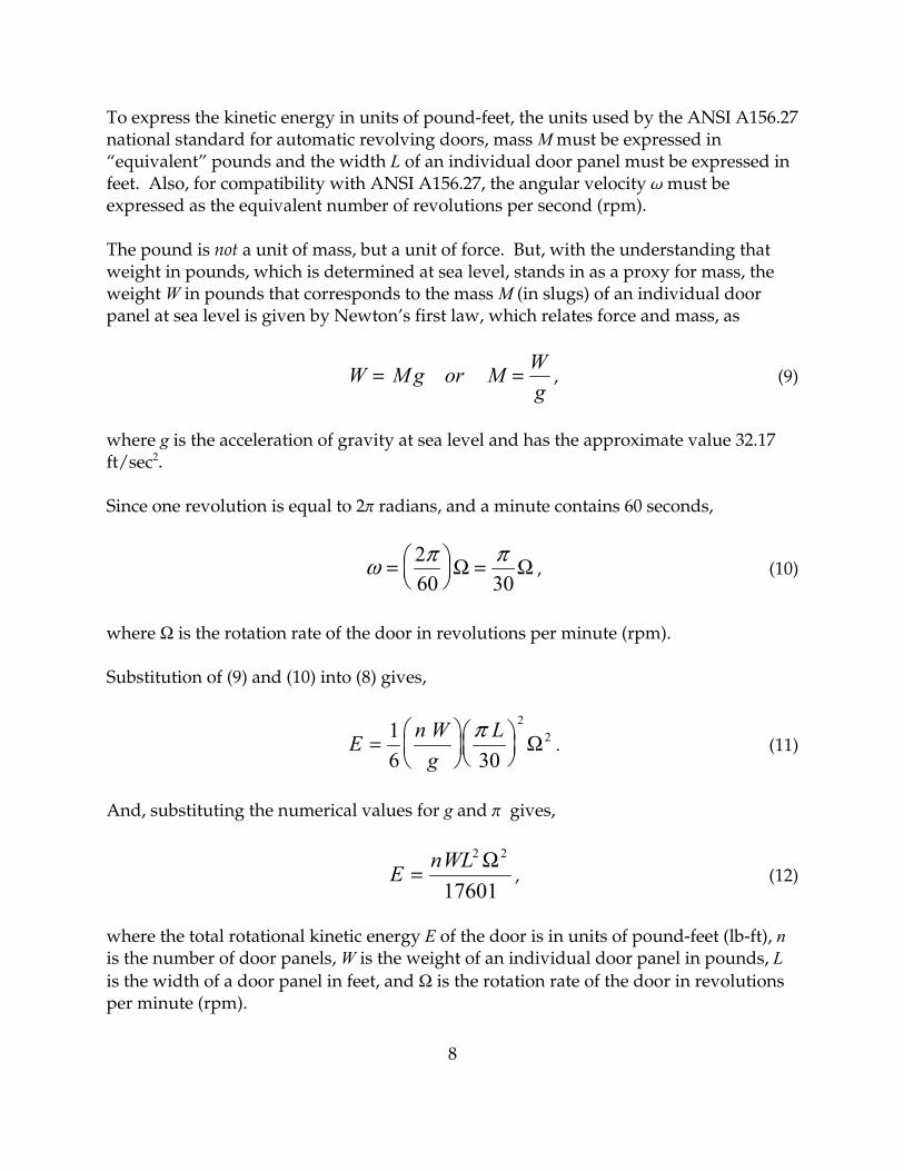
To express the kinetic energy in units of pound-feet, the units used by the ANSI A156.27national standard for automatic revolving doors, mass M must be expressed in“equivalent” pounds and the width L of an individual door panel must be expressed infeet. Also, for compatibility with ANSI A156.27, the angular velocity w must beexpressed as the equivalent number of revolutions per second (rpm).
The pound is not a unit of mass, but a unit of force. But, with the understanding thatweight in pounds, which is determined at sea level, stands in as a proxy for mass, theweight W in pounds that corresponds to the mass M (in slugs) of an individual doorpanel at sea level is given by Newton’s first law, which relates force and mass, as
, (9)W Mg or M Wg
= =
where g is the acceleration of gravity at sea level and has the approximate value 32.17ft/sec2.
Since one revolution is equal to 2p radians, and a minute contains 60 seconds,
, (10)ω π π= ⎛⎝⎜
⎞⎠⎟
=260 30
Ω Ω
where Ω is the rotation rate of the door in revolutions per minute (rpm).
Substitution of (9) and (10) into (8) gives,
. (11)E n Wg
L=
⎛⎝⎜
⎞⎠⎟⎛⎝⎜
⎞⎠⎟
16 30
22π
Ω
And, substituting the numerical values for g and p gives,
, (12)E nWL=
2 2
17601Ω
where the total rotational kinetic energy E of the door is in units of pound-feet (lb-ft), nis the number of door panels, W is the weight of an individual door panel in pounds, Lis the width of a door panel in feet, and Ω is the rotation rate of the door in revolutionsper minute (rpm).

9
Kinetic Energy Equations for a 3-wing Door without a Core
Letting n = 3 for a 3-wing door without a core and expressing the wing width L in termsof the overall door diameter
, (13)L D=2
the rotational kinetic energy of a 3-wing door with no core is
No core: , (14)E WDwing3
2 2
23468− = Ω
where E3-wing is the rotational kinetic energy of the door in lb-ft, W is the weight of anindividual door wing in pounds, D is the overall diameter of the door in feet and Ω isthe rotation rate of the door in rpm.
Equation (14) can be used to calculate the rotation rate Ω of a 3-wing door without acore that results in the door carrying exactly 2.5 lb-ft of rotational kinetic energy bysolving (14) for Ω with E set to 2.5 lb-ft. The result is,
3-wing no core: . (15)Ω2 5242
. =D W
Likewise, with E set to 7.0 lb-ft, (14) can be solved for the rotation rate Ω of a 3-wingdoor without a core that results in the door carrying exactly 7.0 lb-ft of rotational kineticenergy. The result is,
3-wing no core: . (16)Ω7 0405
. =D W
Kinetic Energy Equations for a 4-wing Door without a Core
And, setting n = 4 for a 4-wing door without a core and using (13) in (12) for the wingwidth L, the rotational kinetic energy of a 4-wing door with no core is
No core: , (17)E WDwing4
2 2
17601− = Ω

10
where E4-wing is the rotational kinetic energy of the door in lb-ft, W is the weight of anindividual door wing in pounds, D is the overall diameter of the door in feet and Ω isthe rotation rate of the door in rpm.
Equation (17) can be used to calculate the rotation rate Ω of a 4-wing door without acore that results in the door carrying exactly 2.5 lb-ft of rotational kinetic energy bysolving (17) for Ω with E set to 2.5 lb-ft. The result is,
4-wing no core: . (18)Ω2 5210
. =D W
Likewise, with E set to 7.0 lb-ft, (17) can be solved for the rotation rate Ω of a 4-wingdoor without a core that results in the door carrying exactly 7.0 lb-ft of rotational kineticenergy. The result is,
4-wing no core: . (19)Ω7 0351
. =D W
3-wing and 4-wing Doors with a Core
The following additional assumptions apply to the derivation of the rotational kineticenergy equations relating to 3-wing and 4-wing doors with a core.
1. The rotating part of the door consists of a number n of identical flat rectangularradially directed panels each rigidly attached along one vertical edge to one vertexof an n-sided regular polygonal core.
2. The n sides of the regular polygonal core to which the radial panels are attachedconsist also of identical flat rectangular panels.
3. The core to which the panels are attached revolves around a vertical axis coincidentwith the geometric center of the polygonal core.
4. Other components of the door that may be in motion, such as a ceiling and the drivemechanism, are not considered here.
The Figure below illustrates the dimensions and naming conventions employed in thederivations using a 3-wing door as an example. However, because the equations fortwo door configurations are to be derived S those for a 3-wing and those for a 4-wingdoor with a core S the kinetic energy equations will first be derived for the general case

11
of a door with n identical radial panels and an n-sided regular polygonal core. Then, nwill be particularized to 3 and 4.
D represents the overall diameter of the door, R the radius of the door, r the radialdistance from the geometric center of the door to a vertex of the polygonal core, l1 thewidth of one side of the regular polygonal core, l2 the width of each radial panel, and jthe internal half-angle subtended by a vertex of the regular polygonal core.
The derivation of the kinetic energy equations for the complete door with a core willstart with the derivation of the kinetic energy contributed by a basic unit consisting of aradial panel and one of the core panels to which it is attached. The complete doorcomprises n such units so that the kinetic energy of the complete door will be n timesthe result derived for the basic unit. The basic unit is illustrated in the Figure belowconsisting of the radial panel l2 and core panel l1.
Figure 2. Dimensions and naming conventionsfor a revolving door with a regular polygonalcore.

12
h is the perpendicular distance from the geometric center of the regular polygonal coreto the center of one side of the core.
The following relationships are clear from Figure 3.
(20)h r= sinϕand
. (21)l r1 2= cosϕ
It is also clear from Figure 2 that
, or . (22)R D l r= = +2 2 r D l= −
2 2
The interior angle subtended by the vertex of a regular plane polygon of n sides is
Figure 3. Basic unitof n-wing door withcore.

13
.π nn−⎛
⎝⎜⎞⎠⎟
2
Consequently,
. (23)ϕ π= −⎛⎝⎜
⎞⎠⎟2
2nn
As a consequence of the assumptions delineated above, the moment-of-inertia of eachdoor panel, radial and core, about its own center-of-mass is equivalent to that of auniform bar rotating about its center. That is, to
(24)I M L= 112
2
where M is the mass of the bar and L is its length. Here, M is the mass of an individualdoor panel and L its width. Combining (5) and (24), the rotational kinetic energy of apanel of mass M and width L due to its rotation about its own center-of-mass is
. (25)E M Lcm( ) = 124
2 2ω
The kinetic energy due to the rotation of the center-of-mass of the panel about the axisof rotation of the door is from (4) with r substituted for r
(26)E Morbit( ) = 12
2 2ρ ω
where r is the radial distance of the center-of-mass of the panel from the axis of rotationof the door.
Using the parallel axis theorem, the total kinetic energy of the panel due to its rigidrotation within the structure of the door is the sum of the two components given by (25)and (26). Namely,
. (27)E E Epanel cm orbit( ) ( ) ( )= +
Let the mass of a core panel be m1 and that of a radial panel m2. From (25), the kineticenergy associated with the rotation of a core panel about its own center-of-mass is

14
, (28)( )E m l m r m rcm1 1
212
12 2 2
12 2 21
2416
16
1( ) cos sin= = = −ω ω ϕ ω ϕ
where (21) for l1 has also been introduced. And, from (26), the kinetic energy associatedwith the rotation of the center-of-mass of a core panel about the axis of rotation of thedoor is
, (29)E m h m rorbit1 1
2 21
2 2 212
12
( ) sin= =ω ω ϕ
where h has been substituted for r and (20) for h has been introduced. Consequently,the total kinetic energy of a core panel is, from (27), (28) and (29),
. (30)( )E m r m rpanel1 1
2 2 22
12 2 21
21
316
1 2( ) sin sin sin= + −⎛⎝⎜
⎞⎠⎟ = +ω ϕ ϕ ω ϕ
And, with the substitution of (22) for r in (30),
. (31)( )E m D lpanel1 1
22
221
6 21 2( ) sin= −⎛
⎝⎜⎞⎠⎟
+ω ϕ
In the same manner, the kinetic energy associated with the rotation of a radial panelabout its own center-of-mass is from (25)
. (32)E m lcm2 2
2221
24( ) = ω
Since the mass distribution of the radial panel is uniform across the width of the panel,the center-of-mass of the radial panel is located at a distance l2/2 from either edge (side)of the panel. Referring to either Figure 2 or 3, it is clear then that the radial distance ofthe center-of-mass of a radial panel from the axis of rotation of the door is
, (33)ρ = + = −⎛⎝⎜
⎞⎠⎟
+ = −r l D l l D l22 2
2
2 2 2
where (22) for r has been introduced.

15
The kinetic energy associated with the rotation of the center-of-mass of a radial panelabout the axis of rotation of the door is found from (26) and (33) to be
. (34)( )E m m D lorbit2 2
2 22
22
212
18
( ) = = −ω ρ ω
The kinetic energy of the combination of a core panel and a radial panel, the basic unitconsidered here, is
,E E E E E E E Eunit cm orbit cm orbit panel cm orbit( ) ( ) ( ) ( ) ( ) ( ) ( ) ( )= + + + = + +1 1 2 2 1 2 2
which, from (31), (32) and (34), is found to be
. (35)( ) ( )E m D l m D l lunit( ) sin= −⎛⎝⎜
⎞⎠⎟
+ + − +⎡
⎣⎢
⎤
⎦⎥
16 2
1 2 18 31
22
22
22
22 2
2
ω ϕ ω
Clearing the fractions from the factors in parentheses and brackets and taking w to theleft gives
. (36)( ) ( ) ( )[ ]{ }E m D l m D l lunit( ) sin= − + + − +ω ϕ2
1 22 2
2 22
22
242 1 2 3
And expanding the factors involving D gives
(37)( )( ) ( ){ }E m D Dl l m D Dl lunit( ) sin= − + + + − +ω ϕ2
12
2 22 2
22
2 22
244 4 1 2 3 6 4
Result (37) can now be particularized for a 3-wing or 4-wing door by setting n equal to 3or 4, respectively. With reference to (23),
, (n = 3) (38a)sin sinϕ π= =6
12
, (n = 4) (38b)sin sinϕ π= =4
12
so that the trigonometric factor in the first term of (37) becomes

16
(n = 3) (39a)1 2 1 2 12
32
22
+ = + ⎛⎝⎜
⎞⎠⎟
=sin ϕ
(n = 4) (39b)1 2 1 2 12
222
+ = + ⎛⎝⎜
⎞⎠⎟
=sin ϕ
Kinetic Energy Equations for a 3-wing Door with a Polygonal Core
A 3-wing door with a polygonal core is comprised of n = 3 units of the type depicted inFigure 3. Thus,
, (40)E nE Ewingunit unit
3 3− = =( ) ( )
where (37) for is to be evaluated for the case n = 3 using (39a). Thus, (37), (39a)E unit( )
and (40) yield
. (41)( ) ( )E m D Dl l m D Dl lwing3
2
12
2 22
22
2 22
832
4 4 3 6 4− = − + + − +⎡⎣⎢
⎤⎦⎥
ω
Grouping by descending powers of D yields
. (42)( ) ( )E D m m Dl m m l m mwing3
22
1 2 2 1 2 22
1 2832
3 6 6 4− = +⎛⎝⎜
⎞⎠⎟
− + + +⎡
⎣⎢⎤
⎦⎥ω
And taking a factor of 6 out of the brackets gives
. (43)( ) ( )E D m m Dl m m l m mwing32
2
1 2 2 1 2 22
1 234 2
2 23− = ⎛
⎝⎜⎞⎠⎟
+ − + + +⎛⎝⎜
⎞⎠⎟
⎡
⎣⎢⎢
⎤
⎦⎥⎥
ω
To express this kinetic energy in units of pound-feet, the units used by the ANSIA156.27 national standard for automatic revolving doors, the masses m1 and m2 must beexpressed in “equivalent” pounds and the width of the radial panel l2 and the overalldoor diameter D expressed in feet. Also, the angular velocity w must be expressed asequivalent revolutions per second for compatibility with ANSI A156.27.
Substituting (9) and (10) into (43) and using the numerical values for g and p gives,

17
, (44)( ) ( )E D w w Dl w w l w wwing3
2
1 2 2 1 2 22
1 221
3911 22 2
3− = ⎛⎝⎜
⎞⎠⎟
+ − + + +⎛⎝⎜
⎞⎠⎟
⎡
⎣⎢⎢
⎤
⎦⎥⎥
Ω
where the total rotational kinetic energy of the door is in units of pound-feetE wing3−
(lb-ft), w1 and w2 are the weights of a core panel and a radial panel, respectively, inpounds, l2 is the width of a radial panel and D the overall door diameter both in feet,and Ω is the rotation rate of the door in revolutions per minute (rpm).
Equation (44) can be used to calculate the rotation rate Ω of the door that results in thedoor carrying exactly 2.5 lb-ft of rotational kinetic energy by solving (44) for Ω with
set to 2.5 lb-ft. The result is,E wing3−
. (45)( ) ( )Ω2 5 2
1 2 2 1 2 22
1 2
98 9
22 2
3
..=
⎛⎝⎜
⎞⎠⎟
+ − + + +⎛⎝⎜
⎞⎠⎟
D w w Dl w w l w w
Equation (44) may likewise be used to determine the rotation rate Ω of the door thatresults in the door carrying exactly 7.0 lb-ft of rotational kinetic energy by solving (44)for Ω with set to 7.0 lb-ft. The result is,E wing3−
. (46)( ) ( )Ω7 0 2
1 2 2 1 2 22
1 2
165
22 2
3
. =⎛⎝⎜
⎞⎠⎟
+ − + + +⎛⎝⎜
⎞⎠⎟
D w w Dl w w l w w
Kinetic Energy Equations for a 4-wing Door with a Polygonal Core
A 4-wing door with a polygonal core is comprised of n = 4 units of the type depicted inFigure 3. Thus,
, (47)E nE Ewingunit unit
4 4− = =( ) ( )
where (37) for is now to be evaluated for the case n = 4 using (39b). Thus, (37),E unit( )
(39b) and (47) yield

18
. (48)( ) ( )[ ]E m D Dl l m D Dl lwing4
2
12
2 22
22
2 22
62 4 4 3 6 4− = − + + − +ω
Grouping by descending powers of D yields
. (49)( ) ( ) ( )[ ]E D m m Dl m m l m mwing4
22
1 2 2 1 2 22
1 262 3 2 4 3 4 2− = + − + + +ω
And taking a factor of 2 out of the brackets gives
. (50)( ) ( ) ( )E D m m Dl m m l m mwing4
2 2
1 2 2 1 2 22
1 23 22 3 4 3 2 2− = + − + + +
⎡
⎣⎢
⎤
⎦⎥
ω
Substituting (9) and (10) into (50) and using the numerical values for g and p gives,
. (51)( ) ( ) ( )E D w w Dl w w l w wwing4
2
1 2 2 1 2 22
1 221
8801 22 3 4 3 2 2− = + − + + +
⎡
⎣⎢
⎤
⎦⎥Ω
where the total rotational kinetic energy of the door is in units of pound-feetE wing4−
(lb-ft), w1 and w2 are the weights of a core panel and a radial panel, respectively, inpounds, l2 is the width of a radial panel and D the overall door diameter both in feet,and Ω is the rotation rate of the door in revolutions per minute (rpm).
Equation (51) can be used to calculate the rotation rate Ω of the door that results in thedoor carrying exactly 2.5 lb-ft of rotational kinetic energy by solving (51) for Ω with
set to 2.5 lb-ft. The result is,E wing4−
. (52)( ) ( ) ( )Ω2 5 2
1 2 2 1 2 22
1 2
148
22 3 4 3 2 2
. =+ − + + +D w w Dl w w l w w
Equation (51) may likewise be used to determine the rotation rate Ω of the door thatresults in the door carrying exactly 7.0 lb-ft of rotational kinetic energy by solving (51)for Ω with set to 7.0 lb-ft. The result is,E wing4−

19
. (53)( ) ( ) ( )Ω7 0 2
1 2 2 1 2 22
1 2
248
22 3 4 3 2 2
. =+ − + + +D w w Dl w w l w w

20
Kinetic Energy Equations for 2-wing Doors
The rotational kinetic energy equations for a 2-wing revolving door equipped with ashowcase and concentric curved panel attached to the outer end of each wing are nowderived. The following additional assumptions are made.
1. The rotating elements of the door correspond to those illustrated in the plan viewshown in Figure 4 and are assumed to rotate together as a rigid unit.
2. The mass of each flat panel is distributed uniformly in the horizontal directionacross the width of the panel. This assumption is not necessary for the curvedpanels because all points within each curved panel lie at the same distance R fromthe axis of rotation.
3. Other components of the door that may be in motion, such as the ceiling, showcasefloor and the drive mechanism, are not considered here.
Since one vertical edge of each radial panel, of width r and identified by the subscript pin Figure 4, is coincident with the axis of rotation, and since, by (6), the moment-of-inertia of each panel about its end and, therefore, about the axis of rotation is known, itis not necessary to invoke the parallel axis theorem for the radial panels. Rather, themoment-of-inertia (6) can be used directly to express the rotational kinetic energy of theradial panels.
By (6), the moment-of-inertia about the axis of rotation of each radial panel is
, (54)I m rwgrp p
p= =13
13
2 2
where Ip is the moment-of-inertia about the axis of rotation, mp is the mass of the panel,wp is the weight of the panel, r is the width of the panel and g is the acceleration ofgravity at sea level. The approximate value of g is 32.17 ft/sec2. Newton’s first lawrelating force, mass and acceleration has been used in (54) to express the mass of theradial panel mp in terms of the weight of the panel wp at sea level.

21
Since the elements of mass of the curved panels identified by the subscript c in Figure 4all lie at the same distance R from the axis of rotation, the moment-of-inertia of eachcurved panel about the axis of rotation is simply
, (55)I m R wgRc c
c= =2 2
where again Newton’s law has been used to express the mass of the curved panel interms of its weight at sea level.
The moments-of-inertia about the axis of rotation at the geometric center of the door ofthe remaining flat showcase panels of widths l1 and l2 and identified by the subscripts s1and s2 in Figure 4, are derived using the parallel axis theorem.
The moment-of-inertia about the center-of-mass of each showcase panel is given by theformula for the moment-of-inertia about its center of a bar of uniform mass
Figure 4. Plan view of the revolving elements of the 2-wingrevolving door.

22
, (56)I ml= 112
2
where m is the mass of the bar and l the length of the bar. In this application, m is themass of the respective showcase panel and l is its width.
To calculate the moments-of-inertia of the centers-of-mass of the flat showcase panelsabout the axis of rotation, it is necessary first to have an expression for the distance ofthe center-of-mass of each showcase panel from the axis of rotation. Because the massesof the showcase panels are assumed to be uniform in the horizontal direction, thecenter-of-mass of each such panel is located midway along the panel. One end of eachpanel lies at a distance r from the axis of rotation, and the other end at a distance R. Ifthe width of the panel is l, it is necessary, therefore, to develop an expression for thedistance r illustrated in Figure 5.
Treating R, r, r and l as vectors, the perimeter triangle in Figure 5 satisfies therelationship
where “@” represents the vector inner, or “dot”, product and the square of a vectorrepresents the square of the magnitude of the vector. Likewise, the upper triangle inFigure 5 satisfies the relationship
r R l R l2 2 2 2= + − ⋅
Figure 5. Distance r to centerof mass of showcase panel.

23
.ρ2 22
4= + − ⋅R l R l
When the first of these relationships is used to eliminate R @ l from the second, the resultis
. (57)( )ρ2 2 221
2 4= + −r R l
Using (56) and (57), the total moment-of-inertia of the first showcase panel with respectto the axis of rotation at the center of the door is, from the parallel axis theorem (2),
,( )I m l m r R ls s1 1 1
21
2 2 121
1212 4
= + + −⎡
⎣⎢
⎤
⎦⎥
or
. (58)( )I wgr R w
gls s
11 2 2 1
121
216
= + −
where Newton’s law has again been used to express the mass of the panel in terms of itsweight at sea level.
In exactly the same way, the total moment-of-inertia of the second showcase panelabout the axis of rotation at the geometric center of the door is
. (59)( )I wgr R w
gls s
22 2 2 2
221
216
= + −
The total moment-of-inertia of all rotating components of the door illustrated in Figure4, taking into account also that there are two identical sections to the door, is twice thesum of (54), (55), (58) and (59). That is
. (60)( ) ( )Igw R w w r R w l w l w rc
s ss s p= + + + − + +⎡
⎣⎢⎤⎦⎥
22
16
13
2 1 2 2 21 1
22 2
2 2

24
The expression (1) for the rotational kinetic energy of the door can be expressed interms of the rotation rate of the door in revolutions per minute (rpm) by substituting(10) into (1) to get
. (61)E I= ⎛⎝⎜
⎞⎠⎟
12 30
22π Ω
where Ω is the rotation rate of the door in revolutions per minute.
When (60) is substituted for I in (61) and the numerical values of p and g utilized, thefinal result for the rotational kinetic energy of the 2-wing revolving door is
(62)( ) ( )E w R w w r R w l w l w rcs s
s s p= ++
+ − + +⎡⎣⎢
⎤⎦⎥
129336 2
16
13
2 1 2 2 21 1
22 2
2 2 2
.Ω
where the rotational kinetic energy E is in units of pound-feet; the weights wc, ws1, ws2and wp of the door components are in pounds; the dimensions r, R, l1 and l2 are in feet;and the rotation rate of the door Ω is in revolutions per minute.
Kinetic Energy Equations for 2-wing Doors with Showcases
With the substitution
,R D=2
equation (62) can be written equivalently as
(63)( ) ( )[ ] ( )E D w w w r w w w w l w lwing c s s s s p s s2
2
1 22
1 2 1 12
2 22 21
176013
42 3 2− = + + + + + − +
⎡
⎣⎢
⎤
⎦⎥Ω
where again the rotational kinetic energy E2-wing is in units of pound-feet; the weights wc,ws1, ws2 and wp of the door components are in pounds; the dimensions r, D, l1 and l2 are infeet; and the rotation rate of the door Ω is in revolutions per minute.
Equation (63) can be solved for the rotation rate of the door in revolutions per minute Ωat which the door exhibits 2.5 lb-ft and 7.0 lb-ft of rotational kinetic energy. The resultsare

25
(64)( ) ( )[ ] ( )Ω2 5 2
1 22
1 2 1 12
2 22
2103
42 3 2
. =+ + + + + − +D w w w r w w w w l w lc s s s s p s s
and,
(65)
( ) ( )[ ] ( )Ω7 0 2
1 22
1 2 1 12
2 22
3513
42 3 2
. =+ + + + + − +D w w w r w w w w l w lc s s s s p s s

26
Kinetic Energy Equations for Showcase Floors
The kinetic energy equations derived to this point have been simple enough that theycan be expressed for each door type in a single, closed-form expression. However, thisis not the case with the derivation of the kinetic energy equations for the showcasefloors associated with a 2-wing revolving door. Rather, the derivation will resultinstead in a series of mathematical steps S an algorithm S for the computation of thekinetic energy.
There are two basic reasons why the equations for the showcase floors are so muchmore complicated than those considered thus far. The first is that the shape of theshowcase floor is not a simple straight line or curve of constant radius, as are the flatand curved panels in the previous derivations. Instead, the showcase floor has aroughly triangular shape, being bounded on two sides by flat showcase panels and onthe third side by a curved panel of constant radius. The self moment-of-inertia andcenter-of-mass location of this shape, required for application of the parallel axistheorem, are not readily available in the handbooks and other sources, therebyimmediately introducing the added complication that these parameters must be derivedab initio.
The second reason is that the showcase floor becomes, in general, a different shape if itsrelative dimensions change. For example, a fundamentally new shape arises if the widthof one of the two flat showcase panels changes while the other panel sizes remain fixed. The new shape cannot be made congruent with the original shape by merely changingthe overall scale. This is not true of the straight and curved lines considered thus far. The result is that the kinetic energy equations for the showcase floor are necessarilymore complicated because they must encode the infinity of unique shapes that the floorcould have.
Method
In order to overcome the additional complexity imposed by the shape of the showcasefloor, the kinetic energy derivation will be broken into the sum of three parts, each ofwhich involves a shape that is much more easily analyzed.
The shaded area in Figure 6 below illustrates the general shape of a conventionalshowcase floor. It is bounded on two sides by flat showcase panels and on the third,peripheral side by a curved panel of constant radius. To simplify the analysis, the floorwill be considered as the sum of three parts S the two right triangles labeled “trianglel” and “triangle 2” plus the segment of the circle bounded by the curved panel on theright and, on the left, by the chord between the points at which the flat showcase panels

27
meet the curved panel. The self moment-of-inertia of a right triangle and the knownlocation of the center-of-mass of a right triangle will be used, along with the parallelaxis theorem, to derive the contributions to the kinetic energy from the two righttriangles comprising part of the showcase floor. On the other hand, due to its geometryand curvature centered on the axis of rotation, the kinetic energy contributed by thesegment of a circle will be derived by direct integration, with no need to invoke theparallel axis theorem. The kinetic energy of the complete showcase floor is equal to thesum of the kinetic energies of these three parts.
Although the non-conventional showcase floor shape illustrated in Figure 7 above maybe rarely, if ever, encountered, the RDEC kinetic energy equations for showcase floorshave been generalized to handle this case as well. The method is essentially the same asthat just described for the conventional shape illustrated in Figure 6 except that thecontributions to the kinetic energy of the showcase floor from the two right triangles aresubtracted from, rather than added to, the contribution from the segment of a circle. Ascan be seen in Figure 7, the shaded area representing the showcase floor is equal to thearea of the segment of a circle bounded on the left by the chord, minus the areas of thetwo right triangles. The ability to add or subtract, as appropriate, the contributionsfrom the right triangles is all that is required for RDEC to be able to cover both casesillustrated in Figures 6 and 7.
Figure 6. Showcase floor, conventionalshape.
Figure 7. Showcase floor, non-conventional shape.

28
Algorithm
Figure 8 below displays the parameters that enter into the derivation of the kineticenergy equations for a showcase floor. Not defined in Figure 8, but also required, arethe weight W in pounds of a single showcase floor and the rotation rate of the door w inradians per second. Right triangle 1 has l1 as its hypotenuse, right triangle 2 has l2 as its
hypotenuse and the segment of the circle has chord b. r is the perpendicular bisector ofthe chord b extending from the axis of rotation. h is the common height of the two righttriangles 1 and 2, and is also perpendicular to the chord b. CM1 and CM2 represent thelocations of the centers-of-mass of triangles 1 and 2, though they are not necessarilypositioned to scale in the diagram in Figure 8.
The first step is to determine the angles about the axis of rotation j1 and j2 subtendedby the two flat showcase panels l1 and l2, respectively. These are found from the
Figure 8. Diagram illustrating parametersused in the showcase kinetic energy equationderivations.

29
generalization of the Pythagorean theorem to the triangles of sides R, r and l1, and of R, rand l2. Namely
l R r Rr l R r Rr12 2 2
1 22 2 2
22 2= + − = + −cos cosϕ ϕand
from which it follows that
(66a)ϕ11
2 212
2= + −⎛
⎝⎜
⎞⎠⎟−cos R r l
Rrand,
(66b)ϕ21
2 222
2= + −⎛
⎝⎜
⎞⎠⎟−cos R r l
Rr
From Figure 8 it is clear that the angle q subtended by the chord b is
. (67)θ ϕ ϕ= +1 2
Noting that r is the perpendicular bisector of chord b, it can be seen immediately fromFigure 8 and is also well known from mensuration that the length of the chord b is
. (68)b R= 22
sinθ
Likewise, r can be found from inspection of Figure 8, and is
. (69)ρ θ= Rcos2
Figure 9 below illustrates the situation in which, as described under Method on page 26,the triangles 1 and 2 subtract from, rather than add to, the area of the segment of acircle. By comparing Figures 8 and 9, it is clear that the projection of r in the direction ofthe perpendicular bisector r of the chord b is less than r when the triangles add to, andgreater than r when the triangles subtract from, the segment of a circle. The projectionof r in the direction of r is from either Figure 8 or 9
(70)proj r r= −⎛⎝⎜
⎞⎠⎟
= −⎛⎝⎜
⎞⎠⎟
cos cosϕ θ ϕ ϕ1
1 2
2 2

30
where (67) has been substituted for q in (70). Thus, to flag the addition or subtraction ofthe areas and kinetic energies of triangles 1 and 2, a variable s is set according to
IF (proj > r), s = !1 (71a)
IF (proj # r), s = +1 (71b)
When s = +1, the effects of triangles 1 and 2 are to be added to those of the segment of acircle. And, when s = !1, the effects of the triangles are to be subtracted from thesegment of a circle. When proj = r, the common height h of triangles 1 and 2 is zero sothat, whether added to or subtracted from the segment of a circle, the triangles in thiscase have no effect on the kinetic energy.
Figure 9. Illustrating the situation in whichtriangles 1 and 2 subtract from the area of thesegment of the circle.

31
From either Figure 8 or 9, the Pythagorean theorem applied to right triangles 1 and 2gives
(72)l b h12
12 2= +
and
. (73)( )l b b h b bb b h22
12 2 2
1 12 22= − + = − + +
The length of the side b1 of triangle 1 coincident with the chord b can be found bysubtracting (73) from (72) and solving for b1 to get
. (74)b l l bb1
12
22 2
2= − +
And, the common height h of triangles 1 and 2 in terms of l1 and b1 is found from (72) tobe
. (75)h l b= −12
12
In order to apply the parallel axis theorem to the right triangles 1 and 2, it is necessaryto compute the radial distances from the axis of rotation of the centers-of-mass of thetwo triangles. As shown in Appendix 1, the center-of-mass of a right triangle withperpendicular sides a and b is located at a distance a/3 from the right angle along theside of length a and at a distance b/3 from the right angle along the side of length b.
It is easily deduced from either Figure 8 or 9 and the result from Appendix 1 that, sincer divides the chord b into two equal parts of length b/2, the magnitude of thedisplacement of the center-of-mass of triangle 1 normal to r is
. (76)b b2
23 1−
And, clearly, the displacement of the center-of-mass of right triangle 1 along r is plus-or-minus h/3 depending upon whether the contribution of triangle 1 is to be added toor subtracted from the contribution of the segment of a circle. That is, upon the variables defined by (71). If s is +1, then h/3 must be subtracted from r. Otherwise, if s is !1,h/3 must be added to r.

32
Using the Pythagorean theorem and the normal and parallel displacements from thepoint at which r intersects the chord b, the squared magnitude of the radial distance r1
of the center-of-mass of triangle 1 from the axis of rotation is
. (77)ρ ρ12
2
1
2
3 223
= −⎛⎝⎜
⎞⎠⎟
+ −⎛⎝⎜
⎞⎠⎟
sh b b
It is likewise easily deduced from either Figure 8 or 9 and the result from Appendix 1that, since r divides the chord b into two equal parts of length b/2, the magnitude of thedisplacement of the center-of-mass of triangle 2 normal to r is
. (78)b b6
23 1−
As before, the magnitude of the displacement of the center-of-mass of triangle 2 along ris h/3 with variable s determining whether h/3 is to be added to or subtracted from r.
Again using the Pythagorean theorem and the normal and parallel displacements fromthe point at which r intersects the chord b, the squared magnitude of the radial distancer2 of the center-of-mass of triangle 2 from the axis of rotation is
. (79)ρ ρ22
2
1
2
3 623
= −⎛⎝⎜
⎞⎠⎟
+ −⎛⎝⎜
⎞⎠⎟
sh b b
The next step is to compute the areas of triangles 1 and 2 and the segment of the circle. The areas of the triangles are
(80a)A sb h1 112
=
and
(80b)( )A s b b h2 112
= −
where the factor of s has been included in the equations for the areas in ordersubsequently to cause the contributions of the triangles either to add to or subtract fromthe contribution from the segment of a circle.
The area of the segment of a circle is

33
. (81)( )A Rs = −
2
2θ θsin
This relationship is well known from mensuration and can be found in virtually anymathematical handbook.
Assuming that all length measurements are in feet, the area mass density l of theshowcase floor in slugs per square foot can be calculated from the weight W of theshowcase floor, the areas (80a), (80b) and (81) and the acceleration of gravity at sea levelg = 32.17 ft/sec2 as
(82)λ =+ +
11 2gW
A A As
where (9) has been used to relate mass in slugs to weight in pounds. Given the signattached to the areas A1 and A2 by s in (80a) and (80b), (82) correctly accounts for theactual area of the showcase floor indicated by the grey areas in Figures 6 and 7.
As shown in Appendix 2, the moment-of-inertia of a right triangle with perpendicularsides of length a and b about its own center-of-mass is
. (83)( )I M a bcm = +18
2 2
where M is the mass of the triangle.
The mass M1 of triangle 1 is λ A1 and the lengths of its perpendicular sides are h and b1. Therefore, the kinetic energy contributed by the rotation of triangle 1 about its owncenter-of-mass is, using (5)
. (84)( )E A h b A lcm1
1 212 2 1
12 2
36 36( ) = + =λ ω λ ω
And, the kinetic energy contributed by rotation of the center-of-mass of triangle 1 aboutthe axis of rotation is from (4)
. (85)E M Aorbit1 1 1
2 21 1
2 212
12
( ) = =ρ ω λ ρ ω

34
The total contribution to the kinetic energy from triangle 1 is the sum of (84) and (85),
, (86)E A l A l1
112 1
22 1
12 1
22
2 18 182 38 18= +
⎛⎝⎜
⎞⎠⎟ = +
⎛⎝⎜
⎞⎠⎟
λ ρ ω λ ρ.
Ω
where in the last step (10) has been used to relate w in radians per second to Ω in rpmand the numerical value of p has been applied. Again, the sign of E1 determined by thesign of A1 will cause the kinetic energy E1 due to triangle 1 properly to be added to orsubtracted from the kinetic energy of the segment of a circle. With all lengths measuredin feet and the mass of the showcase floor expressed in “equivalent” pounds, E1 from(86) is in units of pound-feet (lb-ft).
Carrying through in the same way for triangle 2, but with area A2, radial distance r2 andperpendicular sides of length h and b ! b1, the contribution to the kinetic energy E2 bytriangle 2 is
(87)E A l A l2
222 2
22 2
22 2
22
2 18 182 38 18= +
⎛⎝⎜
⎞⎠⎟ = +
⎛⎝⎜
⎞⎠⎟
λ ρ ω λ ρ.
Ω
where again (10) has been used in the last step to relate w in radians per second to Ω inrpm and the numerical value of p has been applied. And as before, the sign of E2
determined by the sign of A2 will cause the kinetic energy E2 due to triangle 2 properlyto be added to or subtracted from the kinetic energy of the segment of a circle. With alllengths measured in feet and the mass of the showcase floor expressed in “equivalent”pounds, E2 from (87) is in units of lb-ft.
As derived in Appendix 3, the moment-of-inertia of the segment of a circle about theaxis of rotation is
. (88)I Rs = + −⎛
⎝⎜⎞⎠⎟
⎡
⎣⎢⎤
⎦⎥λ θ θ θ4
2
423 2
1sin sin
Since the moment-of-inertia of the segment of a circle about the axis of rotation isalready known, it is not necessary to invoke the parallel axis theorem. Rather, thecontribution to the kinetic energy from the segment of a circle can be found directly bysubstituting (88) into (1) with the result

35
. (89)E I Rs s= = + −⎛
⎝⎜⎞⎠⎟
⎡
⎣⎢⎤
⎦⎥12 8
23 2
124
2 2ω λ θ θ θ ωsin sin
When (10) relating w in radians per second to Ω in rpm is substituted into (89) and thenumerical value of p is applied, the result is
. (90)E Rs = + −⎛
⎝⎜⎞⎠⎟
⎡
⎣⎢⎤
⎦⎥λ θ θ θ4
2 2
729 523 2
1.
sin sin Ω
If all lengths are measured in feet and the mass of the showcase floor is expressed in“equivalent” pounds, Es from (90) is in units of lb-ft.
Let G1, G2 and Gs equal the coefficients of Ω 2 in (86), (87) and (90), respectively. That is,
, (91a)Γ11
12 1
2
182 38 18= +
⎛⎝⎜
⎞⎠⎟
λ ρA l.
, (91b)Γ22
22 2
2
182 38 18= +
⎛⎝⎜
⎞⎠⎟
λ ρA l.
and,
. (91c)ΓsR= + −⎛
⎝⎜⎞⎠⎟
⎡
⎣⎢⎤
⎦⎥λ θ θ θ4
2
729 523 2
1.
sin sin
The total rotational kinetic energy contributed by the two identical showcase floors isgiven by twice the sum of (86), (87) and (90). That is,
. (92)( ) ( )E E E Efloors s s= + + = + +2 21 2 1 22Γ Γ Γ Ω
The rate in rpm at which the two showcase floors would have to rotate to contributeexactly 2.5 lb-ft of kinetic energy is found from (92) by setting Efloors to 2.5 lb-ft andsolving for Ω. The result is
. (93)ΩΓ Γ Γ2 5
1 2
1118.
.=+ + s

36
Likewise, by setting Efloors in (92) to 7.0 lb-ft and solving for Ω, the rate in rpm at whichthe two showcase floors would have to rotate to contribute exactly 7.0 lb-ft of kineticenergy is found to be
. (94)ΩΓ Γ Γ7 0
1 2
1871.
.=+ + s

37
Kinetic Energy Equations for Ceiling, Point & Extended Objects
Ceilings
The RDEC program enables the user to incorporate a co-rotating ceiling in thecalculation of the kinetic energy of the revolving door. The following assumptions aremade.
1. The ceiling is circular.
2. The distribution of the mass of the ceiling is distributed uniformly over thecircular ceiling.
3. The ceiling co-rotates with the door.
4. The geometric center of the ceiling coincides with the axis of rotation of thedoor.
Because the center-of-mass of a circular uniformly distributed mass is located at thegeometric center of the circle and, given the assumption that the center of the ceilingcoincides with the axis of rotation of the door, it is not necessary to invoke the parallelaxis theorem in order to derive an equation for the rotational kinetic energy contributedby a co-rotating ceiling. Rather, the derivation can begin immediately with the wellknown moment-of-inertia about the geometric center of a plane circular uniformlydistributed mass distribution
(95)I MR= 12
2
where M is the total mass of the ceiling and R is the radius of the ceiling.
The kinetic energy of the ceiling is found by substituting (95) into (1) giving
(96)E MRceiling = 14
2 2ω
where w is the rotation rate of the door and ceiling in radians per second.
Using (10) to relate rotation rate w in radians per second to Ω in rpm, (9) to relate themass M of the ceiling to its weight W in pounds, and the fact that the radius R is half thediameter D of the ceiling gives, from (96)

38
. (97)E WDg
WDceiling = ⎛
⎝⎜⎞⎠⎟
=2 2
22
2
16 30 46936π Ω Ω
The numerical value of p and the approximate value of g at sea level of 32.17 ft/sec2
have been substituted to form the right hand expression in (97). The units of Eceiling from(97) will be pound-feet (lb-ft) if the weight W of the ceiling is in pounds and thediameter D of the ceiling is in feet.
Equation (97) can be used to calculate the rotation rate Ω at which the ceiling wouldcarry exactly 2.5 lb-ft of rotational kinetic energy by solving (97) for Ω with Eceiling set to2.5 lb-ft. The result is
. (98)Ω2 5343
. =D W
Likewise, equation (97) can be used to calculate the rotation rate Ω at which the ceilingwould carry exactly 7.0 lb-ft of rotational kinetic energy by solving (97) for Ω with Eceilingset to 7.0 lb-ft. The result is
. (99)Ω7 0573
. =D W
Extended Objects
In order to accommodate inclusion in the kinetic energy calculations the effects of otherobjects whose kinetic energy equations have not been included within the RDECprogram explicitly, RDEC allows the user to characterize such additional objects bytheir total mass, expressed by weight at sea level, the location within the door of theircenters-of-mass and, if significant, their moments-of-inertia about their own centers-of-mass. In this way, the effects on the overall kinetic energy of the door due to virtuallyany additional co-rotating object or objects can be accounted for properly. When themoment-of-inertia of an additional object about its own center-of-mass is significant, itis referred to as an “extended object” in the nomenclature of RDEC.
Calculation of the rotational kinetic energy starts in this case with the parallel axistheorem (2)
(2)I Mr Icm= +2
2 Note that both the mass M and the moment-of-inertia Icm are divided by g in orderto be expressed in terms of weight in pounds as a proxy for the mass in slugs.
39
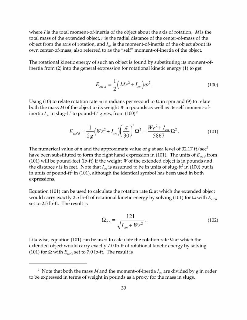
where I is the total moment-of-inertia of the object about the axis of rotation, M is thetotal mass of the extended object, r is the radial distance of the center-of-mass of theobject from the axis of rotation, and Icm is the moment-of-inertia of the object about itsown center-of-mass, also referred to as the “self” moment-of-inertia of the object.
The rotational kinetic energy of such an object is found by substituting its moment-of-inertia from (2) into the general expression for rotational kinetic energy (1) to get
. (100)( )E Mr Iext d cm' = +12
2 2ω
Using (10) to relate rotation rate w in radians per second to Ω in rpm and (9) to relateboth the mass M of the object to its weight W in pounds as well as its self moment-of-inertia Icm in slug-ft2 to pound-ft2 gives, from (100) 2
. (101)( )EgWr I Wr I
ext d cmcm
' = + ⎛⎝⎜
⎞⎠⎟
= +12 30 5867
22
22
2π Ω Ω
The numerical value of p and the approximate value of g at sea level of 32.17 ft/sec2
have been substituted to form the right hand expression in (101). The units of Eext’d from(101) will be pound-feet (lb-ft) if the weight W of the extended object is in pounds andthe distance r is in feet. Note that Icm is assumed to be in units of slug-ft2 in (100) but isin units of pound-ft2 in (101), although the identical symbol has been used in bothexpressions.
Equation (101) can be used to calculate the rotation rate Ω at which the extended objectwould carry exactly 2.5 lb-ft of rotational kinetic energy by solving (101) for Ω with Eext’dset to 2.5 lb-ft. The result is
. (102)Ω2 5 2
121. =
+I Wrcm
Likewise, equation (101) can be used to calculate the rotation rate Ω at which theextended object would carry exactly 7.0 lb-ft of rotational kinetic energy by solving(101) for Ω with Eext’d set to 7.0 lb-ft. The result is

40
. (103)Ω7 0 2
203. =
+I Wrcm
Point Objects
When the moment-of-inertia of an object to be included in the rotational kinetic energycalculations of the door is negligible, the RDEC program allows the user to characterizesuch additional objects by their total mass, expressed by weight at sea level, and thelocation within the door of their centers-of-mass. In this way, the effects on the overallkinetic energy of the door due to any such additional co-rotating objects can beaccounted for properly. When the moment-of-inertia of an additional object about itsown center-of-mass is not significant and can be ignored, it is referred to as a “pointobject” in the nomenclature of RDEC.
Since the only difference between “extended objects” and “point objects” is that themoments-of-inertia of the latter about their own centers-of-mass are not significant andcan safely be ignored, the kinetic energy equations pertaining to point objects can beobtained immediately from those already derived for extended objects merely byomitting Icm from the relevant expressions. Thus, from (101)
(104)E Wrpoint =
22
5867Ω
where W is the weight in pounds of the point object, r is the radial distance of its center-of-mass from the axis of rotation, and Ω is the rotation rate of the door in rpm. Withthese units for W and r, Epoint is in units of pound-feet (lb-ft).
The rate at which the point object would have to rotate in order to carry exactly 2.5 lb-ftof kinetic energy is found from (102) by omitting Icm and is
. (105)Ω2 5121
. =r W
And likewise, the rate at which the point object would have to rotate in order to carryexactly 7.0 lb-ft of kinetic energy is found from (103) by omitting Icm and is
. (106)Ω7 0203
. =r W

41
Appendix 1
Center-of-mass of a Right Triangle
The vector location of the center-of-mass of any mass distribution is defined as
(1)RM
r dm= ∫1
where is the vector location of the center-of-mass and M is the total mass of the massRdistribution.
Assume that the area mass density of the triangle is uniform with value λ. The totalmass of the right triangle is the product of λ and its area. That is
. (2)M ab= 12
λ
The differential mass element dm is
(3)dm dydx= λ
Figure 1. Right triangle with perpendicular sides oflengths a and b.

42
and the vector location of the differential mass element in the integrand of (1) is
(4)r e x e yx y= +$ $
where and are unit vectors in the x and y directions, respectively. The equation$ex $eydescribing the hypotenuse of the right triangle in Figure 1 is
. (5)y bax=
From (1) and the above definitions, the center-of-mass of the right triangle illustrated inFigure 1 is
( )RM
e x e y dydxx y
xa ba= + =∫∫
λ$ $
00
. (6)= +∫ ∫ ∫∫$ $eM
x dydx eM
ydydxx
a
y
x xaba
baλ λ
0 0 00
Evaluating the inner integrals on y in (6),
. (7)R eMba
x dx eMba
x dxx
a
y
a= +∫ ∫$ $
λ λ2
0
2
22
02
And evaluating the remaining integrals on x in (7),
. (8)R eMbaa e
Mbaa
x y= +$ $λ λ3 2
2
3
3 2 3
When (2) for M is inserted into (8) and the fractions are cleared, the final result is
. (9)R e a e bx y= +$ $23
13

43
In words, the center-of-mass of the right triangle illustrated in Figure 1 is located at adistance (2/3) a from the origin along the side of length a, or, equivalently, (1/3) a fromthe right angle of the triangle. Likewise, the location of the center-of-mass is at adistance of (1/3) b from the origin along the side of length b which, in this instance, isalso (1/3) b from the right angle of the triangle. That is, the center-of-mass of a righttriangle of perpendicular sides of length a and b is located at a distance of (1/3) a alongthe side of length a from the right angle, and at a distance of (1/3) b along the side oflength b from the right angle, as illustrated in the Figure below.
Figure 2. Center-of-mass of a right triangle relative tothe location of the right angle.

44
Appendix 2
Moment-of-inertia of a Right Triangle
The so-called polar moment-of-inertia of a mass distribution is defined about the originof coordinates by
(1)I r dm= ∫ 2
where I is the moment-of-inertia, dm is the differential mass element, and r2 is the squareof the distance of the differential mass element from the origin.
Assuming that the triangle has uniform area mass distribution λ, the differential masselement dm is
. (2)dm dydx= λ
The square of the distance of the differential mass element from the origin with respectto which the moment-of-inertia is to be calculated is
Figure 1. Right triangle with perpendicular sides oflengths a and b, with center-of-mass location asderived in Appendix 1.

45
. (3)r x y2 2 2= +
The equation describing the hypotenuse of the right triangle illustrated in Figure 1 is
. (4)y bax=
From (1) and the above definitions, the moment-of-inertia of the illustrated righttriangle about the origin of coordinates in Figure 1 is
( )I x y dydxba xa
02 2
00= + =∫∫λ
. (5)= +∫ ∫ ∫∫λ λx dydx y dydxa x xab
aba2
0 0
2
00
Evaluating the inner integrals on y in (5),
. (6)I ba
x dx ba
x dxa a
03
0
3
33
03= +∫ ∫λ λ
And, evaluating the remaining integrals on x in (6),
. (7)( )I baa b
aa ab a b0
4 3
3
42 2
4 3 4 123= + = +λ λ λ
I0 is the moment-of-inertia of the right triangle illustrated in Figure 1 about the origin,which is coincident with the vertex at the left of the triangle. The moment-of-inertiaabout the center-of-mass Icm of the triangle can be found by applying the parallel axistheorem, equation (2) on page 5 in the Introduction to this document. Since the areamass density λ of the triangle is assumed to be constant over the triangle, the total massM of the triangle is the product of λ and the area of the triangle. That is,
. (8)M ab= 12
λ
Substituting (8) for M into equation (2) on page 5 of the Introduction and with r in Figure1 playing the role of r in (2), and solving for Icm,

46
. (9)I I abcm = −021
2λ ρ
From Figure 1 and the Pythagorean theorem, the squared length of the displacement rof the center-of-mass of the triangle from the origin is
. (10)ρ22 2 2 22
313
49
= ⎛⎝⎜
⎞⎠⎟
+ ⎛⎝⎜
⎞⎠⎟
= +a b a b
Substituting (7) and (10) into (9) gives
. (11)( ) ( ) ( )I ab a b ab a b ab a bcm = + − + = +λ λ λ12
318
436
2 2 2 2 2 2
And, finally, substituting M from (8) into (11) gives for the polar moment-of-inertiaabout the center-of-mass of a right triangle with perpendicular sides a and b anduniform area mass density
(12)( )I M a bcm = +18
2 2
where M is the total mass of the right triangle. Note that a2 + b2 in (12) is equal to thesquare of the hypotenuse of the right triangle.

47
Appendix 3
Moment-of-inertia of a Segment of a Circle
The moment-of-inertia of a mass distribution about the origin of coordinates is
(1)I r dm= ∫ 2
where I is the moment-of-inertia, dm is the differential mass element, and r2 is the squareof the distance of the differential mass element from the origin.
Assuming that the segment of a circle has uniform area mass density λ, in polarcoordinates with origin at the center of the circle, the differential mass element dm is
. (2)dm rdr d= λ ϕ
Figure 1. Variables and dimensions used to integrateover the segment of a circle.

3 See Table of Integrals, Series and Products, I. S. Gradshteyn and I. M. Ryzhik,Integral 2.526(12), Academic Press (1980).
48
The distance r in Figure 1 is
(3)ρ θ= Rcos2
where q is the total angle about the center of the circle subtended by the chord thatdefines the segment of the circle.
From (1) and the above definitions, the moment-of-inertia of the segment of a circleabout the center of the circle in Figure 1 is
. (4)I r dr dR
= ∫∫2 3
0
2λ ϕρ ϕ
θ
sec
Due to symmetry, the integration is carried out only over the upper half of the segmentof a circle with the factor of 2 appearing on the right side of (4) accounting for the entiresegment. That is, the sum of the integrations over both the upper and lower halves ofthe segment.
The inner integral on r in (4) evaluates to
( )14
4 4 4R − ρ ϕsec
so that (4) breaks into the sum of two integrals
. (5)I R d d= −∫ ∫λ ϕ λ ρ ϕ ϕ
θ θ4
0
44
02 22 2 sec
The second integral in (5) is evaluated as follows3
seccos
sincos
sincos
4
0 4 300
2 22
323
ϕ ϕ ϕϕ
ϕϕ
ϕϕ
θ θθ
d d∫ ∫= = +
⎡
⎣⎢
⎤
⎦⎥ =

49
. (6)= +⎡
⎣⎢
⎤
⎦⎥ =
+sin cos sin coscos
sin cos sin cos
cos
ϕ ϕ ϕ ϕϕ
θ θ θ θ
θ
θ
23
2 22
2 2
32
3
40
3
4
2
Use the trigonometric identities
and sin sin cos2 2x x x= cos sin2 21x x= −
in (6) to get
secsin sin cos
cos
4
0
2
4
2
12 2
32
ϕ ϕθ θ θ
θθ
d∫ =+
=
. (7)=−3
2 23
2
2
4
sin sin sin
cos
θ θ θ
θ
With (3) for r and result (7), the second integral in (5) becomes
. (8)λρ ϕ ϕ λ θ θ θθ4
4
0
42
2 423 2
2 sec sin sin sin∫ = −⎛⎝⎜
⎞⎠⎟
d R
The first integral in (5) evaluates to
, (9)λ ϕ λ θ
θ
2 44
4
0
2R d R=∫
and when (8) and (9) are used in (5) the result is finally
. (10)I R= + −⎛
⎝⎜⎞⎠⎟
⎡
⎣⎢
⎤
⎦⎥
λ θ θ θ42
423 2
1sin sin

50
Appendix 4
Moment-of-inertia of Core Floor
Herein are derived the equations for the moment-of-inertia of core floors orindependent core ceilings. Although equations for the kinetic energy of a core floor orceiling do not appear in the RDEC program, the required moment-of-inertia equationsdo appear in the RDEC User’s Manual in connection with an example of the use of theRDEC Extended object option. Therefore, for completeness, their derivations areprovided here.
By “independent core ceiling” it is meant that the core ceiling does not consist of thecentral part of a circular co-rotating ceiling already being accounted for using theCeiling option available in the RDEC Configuration window but, rather, that the ceiling,if it exists, is actually an independent structure whose effect is to be included in thekinetic energy calculations.
In the following, the term “core floor” should be understood to mean any structure,including a ceiling, exhibiting the following characteristics.
1. The surface of the structure is oriented horizontally and is bounded on all sidesby the flat core panels. Thus, the structure has the same size and shape as thecore.
2. The core shape is that of a n-sided regular polygon.
3. The distribution of mass over the surface of the structure is uniform.
4. The distribution of the mass of the structure in the vertical direction isimmaterial.
5. The geometric center of the n-sided regular polygon coincides with the axis ofrotation of the door.
Figure 1 below illustrates a core floor corresponding the a regular pentagon. A 5-sidedcore floor has been chosen for pedagogical purposes to highlight certain aspects of thenature of the derivation and is not meant necessarily to represent a shape that might beencountered in actual practice. It is clear from the Figure that
(1)a r= cosθ2

51
and
(2)b r= sinθ2
Note that the sector of the polygon highlighted in Figure 1 is comprised of two identicalright triangles with perpendicular sides a and b. Equation (7) in Appendix 2 containsthe following expression for the moment-of-inertia about the acute vertex located at theorigin of coordinates of a right triangle with perpendicular sides a and b
(3)( )I ab a b02 2
123= +λ
where λ is the area mass density of the triangle, which is assumed to be uniform. Assuming the origin of coordinates in Figure 1 to be at the geometric center of thepolygon, equation (3) correctly describes the moment-of-inertia about the center of thepolygon of each of the two triangles comprising the polygon sector. Since identicalpairs of triangles exhibiting the same moment-of-inertia as given by (3) can beconstructed within each of the n sectors of the n-sided polygon, the total moment-of-inertia about the geometric center of the entire polygon is
Figure 1. Illustration of a regular polygonal core floorwith n = 5.

52
. (4)( )I nI n ab a bn = = +26
302 2λ
Accounting for both triangles within the sector, the area of each sector of the polygon is
. (5)A ab ab= ⎛⎝⎜
⎞⎠⎟
=2 12
Given that there are n sectors in an n-sided polygon and given the uniform area massdensity λ, the total mass of the polygon is
. (6)M n A n ab= =λ λ
With (6), equation (4) for the moment-of-inertia of the polygon can be expressed interms of the mass of the polygon as
. (7)( )I M a bn = +6
3 2 2
With a and b from (1) and (2) in (7), the moment-of-inertia In is
(8)I Mr Mrn = +⎛
⎝⎜⎞⎠⎟
= +⎛⎝⎜
⎞⎠⎟
22 2
22
63
2 2 62
21cos sin cosθ θ θ
where the trigonometric identity has been used in (8). And, with thesin cos2 21x x= −further trigonometric identity
2 1 22cos cosx x= +
used in (8),
(9)( )I Mr Mrnn = + = +⎛
⎝⎜⎞⎠⎟
2 2
62
62 2cos cosθ π
where the fact that the central angle q subtended by a sector of an n-sided polygon is

53
(10)θ π= 2n
has also been used in (9).
For the specific cases of a 3-sided (equilateral triangle) and a 4-sided (square) regularpolygonal core floor, the respective moments-of-inertia are found from (9) bysubstituting n = 3 and n = 4. The results are
(11)I Mr321
4=
and
(12)I Mr421
3=
where I3 and I4 are the moments-of-inertia about the geometric centers of a 3-sided anda 4-sided regular polygonal core floor, respectively, M is the mass of the floor, and r isthe distance from the geometric center of the polygon to any vertex of the polygon.
Because the geometric center of the polygonal floor is assumed to coincide with the axisof rotation of the door, (11) and (12) also express the moments-of-inertia of therespective core shapes about the axis of rotation of the door.
For the purpose of entering, in English units, the moments-of-inertia given by (11) and(12) as one of the parameters required by the Extended objects option of the RDECprogram, the weight W of the core floor, rather than its true mass M, should besubstituted for M. That is, when using English units with the RDEC Extended objectsoption, the following should be used
(13)I Wr321
4=
and
(14)I Wr421
3=
where I3 and I4 are the moments-of-inertia about the geometric centers of a 3-sided anda 4-sided regular polygonal core floor in units of lb-ft2, respectively, W is the weight of

54
the floor in pounds, and r is the distance from the geometric center of the polygon toany vertex of the polygon in feet.
Note that the substitution of the weight W for the true mass M is required only whenusing English units. Otherwise, when using metric units, equations (11) and (12) shouldbe used with M specified in kilograms and r in meters so that I3 and I4 will be in units ofkg-m2.
Davis Associates, Inc. • 43 Holden Road • Newton, MA U.S.A. 02465-1909617-244-1450