department of the air force headquarters united states...
TRANSCRIPT
DEPARTMENT OF THE AIR FORCE HEADQUARTERS UNITED STATES AIR FORCE WASHINGTON, DC 20330-5140
Reply ToAttn of: CEC
Subject: Engineering Technical Letter (ETL) 91-2: High Altitude Electromagnetic Pulse (HEMP) Hardening in Facilities
TO: SEE DISTRIBUTION LIST
1. Attached for your information and action is the guidance for theplanning, programming, designing, constructing and acceptance testing of newor renovations to existing HEMP barriers in facilities.
2. Purpose. This ETL:
a. Supersedes the HEMP portion of ETL 88-7: TEMPEST and High-AltitudeElectromagnetic Pulse (HEMP) Protection for Facilities, 24 Aug 88.
b. Implements Air Force Regulation (AFR) 80-38, The Air Force SystemsSurvivability Program, 29 Sept 89.
c. Establishes guidelines for determining the degree of hardening C4Iand other mission critical systems during the planning and programmingstages.
d. Provides guidance for developing the Project Requirements andManagement Plan (RAMP).
e. Establishes guidelines from planning through acceptance testing ofHEMP hardened barriers within facilities.
3. Effective Date: This ETL is effective immediately for projects in theFY92 and subsequent MILCON programs. For projects currently under designauthorized by a previous Design Instruction (DI), there is no requirement tomodify the ongoing design process.
4. The point of contact is Mr. R.S. Fernandez at DSN 297-4083 or (202)767-4083.
FOR THE CHIEF OF STAFF
CHARLES L. PEARCE, Colonel, USAFDirector, Military ConstructionOffice of The Civil Engineer 3 Atch 1. Distribution List 2. HEMP Hardening Criteria 3. Index

DISTRIBUTION LIST
DISTRIBUTIONACTION OFFICES
HQ 11TH AF/DEE/DEM/DEPELMENDORF AFB, AK 995506-5001
TIG/APGSCOTT AFB, IL 622250-6001
HQ AFLC/DEE/DEM/DEPWRIGHT-PATTERSON AFB, OH 45433-5001
HQ AFRES/DEE/DEM/DEPROBINS AFB, GA 31098-5000
HQ AFSC/DEE/DEM/DEPANDREWS AFB, DC 20334-5000
HQ ATC/DEE/DEM/DEPRANDOLPH AFB, TX 78148-5001
HQ ESC/LEEECSAN ANTONIO, TX 78243-5001
HQ PACAF/DEE/DEM/DEPHICKAM AFB, HI 96853-5001
HQ MAC/DEE/DEM/DEPSCOTT AFB, IL 62225-5000
HQ SAC/DEE/DEM/DEPOFFUTT AFB, NE 68113-5001
HQ AFSPACECMD/DEE/DEO/DEPPETERSON AFB, CO 80914-5001
HQ TAC/DEE/DEM/DEPLANGLEY AFB, VA 23665-5001
HQ USAFE/DEE/DEM/DEP/SCSAPO NY 09012-5001
HQ USAFE/DERRAF RUISLIP ADM. UKAPO NY 09241-5000
Atch 1 (1 of 4)

HQ AFESC/DEMTYNDALL AFB, FL 3240@1-6001
1100 ABG/DEE/DEM/DEPBOLLING AFB, DC 20332-5000
USAF RGN CIVIL ENGR - EASTERN REGION/ROE77 FORSYTH ST., SUITE 291ATLANTA, GA 30335-6801
USAF RGN CIVIL ENGR - CENTRAL REGION/ROE1114 COMMERCE ST, ROOM 207DALLAS, TX 75242-0216
USAF RGN CIVIL ENGR - WESTERN REGION/ROE630 SANSOME ST, ROOM 1316SAN FRANCISCO, CA 94111-2278
AFRCE-BMS/DEENORTON AFB, CA 92409-6448
AFIT/DEEWPAFB, OH 45433-6583
HQ USAFA/DEMCOLORADO SPRINGS, CO 80840-5671
CHIEF OF ENGINEERS DEPARTMENT OF THE ARMY ATTN: CEEC-ES/ET20 MASSACHUSETTS AVEWASHINGTON, DC 20314-1000
NAVAL FACILITIES ENGINEER COMMANDDEPARTMENT OF THE NAVYATTN: CODE 04/05200 STOVALL STALEXANDRIA, VA 22332-2300
INFO OFFICES
AAFES/EN-CE
ANGSC/DEE/DEOANDREWS AFB, MD 20331-6008
HQ AFCOMS/DEEKELLY AFB, TX 78241-6290
Atch 1 (2 of 4)

DEFENSE MEDICAL FACILITIES OFFICE 6 SKYLINE PLACE 109 LEESBURG PIKEFALLS CHURCH, VA 22041
HQ USAF/CEP/LGS/SCTXWASHINGTON, DC 20330-5000
HQ SSD/DELOS ANGELES AFB, CA 90009-2960
ESD/DEHANSCOM AFB, MA 01731
AD/DEEGLIN AFB, FL 32542-5000
HQ AFOMS/SGSFBROOKS AFB, TX 78235-5000
HQ EID/EISSTINKER AFB, OK 73145-5000
HQ EID/DETINKER AFB, OK 73145-5000
HQ AFISC/SEGNORTON AFB, CA 92409-7001
TIC/APGSCOTT AFB, IL 62225-6001
1839 EIG/EIEEKEESLER AFB, MS 39534-5000
HQ DNA/RAEE6801 TELEGRAPH RDALEXANDRIA, VA 22310-3398
HQ DCA/DTJ(B410)WASHINGTON, DC 20305-2200
SAF/FMABDWASHINGTON, DC 20330-5000
SAF/AQQSWASHINGTON, DC 20330-1000
HQ AGMC/MLMNEWARK AFB, OH 43055-5000
Atch 1 (3 of 4)

WL/NTCBLDG 909KIRTLAND AFB, NM 87117-6008
AFCSC/SRVTSAN ANTONIO, TX 78243-5000
SIO/SYEPETERSON AFB, CO 80914-5001
Atch 1 (4 of 4)

ETL 91-2
4 MARCH 1991
ENGINEERING TECHNICAL LETTER
HIGH-ALTITUDE ELECTROMAGNETIC PULSE (HEMP) HARDENING IN FACILITIES
Department of Air Force United States of America
OFFICE OF THE CIVIL ENGINEER DIRECTOR OF CONSTRUCTION REQUIREMENTS AND OVERSIGHT DIVISION
DISTRIBUTION STATEMENT: APPROVED FOR PUBLIC RELEASE DISTRIBUTION IS UNLIMITED
Table of Contents
Para No. Title Page No.
Part 1 - INTRODUCTION
1 Introduction. . . . . . . . . . . . . . . . . . . . . . . . . 1 Part 2 - GENERAL
2 Referenced Documentation. . . . . . . . . . . . . . . . . . . 23 Definitions . . . . . . . . . . . . . . . . . . . . . . . . . 44 Applications. . . . . . . . . . . . . . . . . . . . . . . . . 74a C4I-Type Facilities. . . . . . . . . . . . . . . . . . . 74b Non-C4I-Type Facilities. . . . . . . . . . . . . . . . . 7
Part 3 - HEMP HARDENING
5 Implementation - General5a C4I-Type Facilities. . . . . . . . . . . . . . . . . . . 85b Aircraft Refueling Facilities. . . . . . . . . . . . . . 85c Non-C4I Mission Critical Facilities. . . . . . . . . . . 9
6 Planning Requirements6a General. . . . . . . . . . . . . . . . . . . . . . . . . 106b Origin of Requirements . . . . . . . . . . . . . . . . . 10
7 Programming Requirements7a General. . . . . . . . . . . . . . . . . . . . . . . . . 127b Command Submittal. . . . . . . . . . . . . . . . . . . . 127c Funding. . . . . . . . . . . . . . . . . . . . . . . . . 12
8 Project Development8a Planning Instructions. . . . . . . . . . . . . . . . . . 138b Requirements and Management Plan (RAMP). . . . . . . . . 138c Field Design Instruction . . . . . . . . . . . . . . . . 138d Project Management Plan (PMP). . . . . . . . . . . . . . 138e CBD Announcement . . . . . . . . . . . . . . . . . . . . 138f A-E Selection. . . . . . . . . . . . . . . . . . . . . . 138g Pre-Project Definition Conference. . . . . . . . . . . . 13
9 Design Requirements9a General. . . . . . . . . . . . . . . . . . . . . . . . . 149b Electromagnetic Barrier. . . . . . . . . . . . . . . . . 149c C4I-Type Systems . . . . . . . . . . . . . . . . . . . . 149d Non-C4I Type Systems . . . . . . . . . . . . . . . . . . 149e Levels of Protection . . . . . . . . . . . . . . . . . . 149f Shielding Materials. . . . . . . . . . . . . . . . . . . 149g Fire Alarm Systems . . . . . . . . . . . . . . . . . . . 159h High Voltage Filters . . . . . . . . . . . . . . . . . . 159i Shield Penetrations. . . . . . . . . . . . . . . . . . . 15
1

gj Shielded Equipment in Shielded Areas . . . . . . . . . . 159k Solid State Systems in Non-C4I Facilities. . . . . . . . 159l Performance Specifications . . . . . . . . . . . . . . . 179m Standard Hardness Critical Items (HCI) . . . . . . . . . 179n Design Checklist . . . . . . . . . . . . . . . . . . . . 179o Design Classification. . . . . . . . . . . . . . . . . . 179p Facility Testability . . . . . . . . . . . . . . . . . . 179q Design Reviews . . . . . . . . . . . . . . . . . . . . . 17
10 Construction Requirements10a Prep for Pre-Construction Conference . . . . . . . . . . 1810b Pre-Construction Conference. . . . . . . . . . . . . . . 1810c Welder/Installer Qualifications. . . . . . . . . . . . . 1810d Inspector Qualifications . . . . . . . . . . . . . . . . 1810e Extended Warranties. . . . . . . . . . . . . . . . . . . 1810f Submittals . . . . . . . . . . . . . . . . . . . . . . . 1910g Construction Monitoring. . . . . . . . . . . . . . . . . 1910h Job Site Visits. . . . . . . . . . . . . . . . . . . . . 2010i Conflicts and Discrepancies. . . . . . . . . . . . . . . 20
11 Testing Requirements11a General. . . . . . . . . . . . . . . . . . . . . . . . . 2111b Security Classification. . . . . . . . . . . . . . . . . 2111c In-Progress Testing. . . . . . . . . . . . . . . . . . . 2111d In-Factory Tests . . . . . . . . . . . . . . . . . . . . 2211e Acceptance Tests . . . . . . . . . . . . . . . . . . . . 2211f Verification Tests . . . . . . . . . . . . . . . . . . . 2411g Life Cycle HEMP Hardening. . . . . . . . . . . . . . . . 25
Appendices
1 HEMP Hardening Shielding Effectiveness Curves2 Equipment Damage Threshold Charts3 HEMP Contacts List4 HEMP Hardening Plan/Program Flowchart5 HEMP Hardening Design Flowchart6 Designer's Checklist7 HEMP Hardening Verification Test Flowchart8 Test Plan Requirements9 Shielded Enclosure Testers
ii
Part 1 - INTRODUCTION
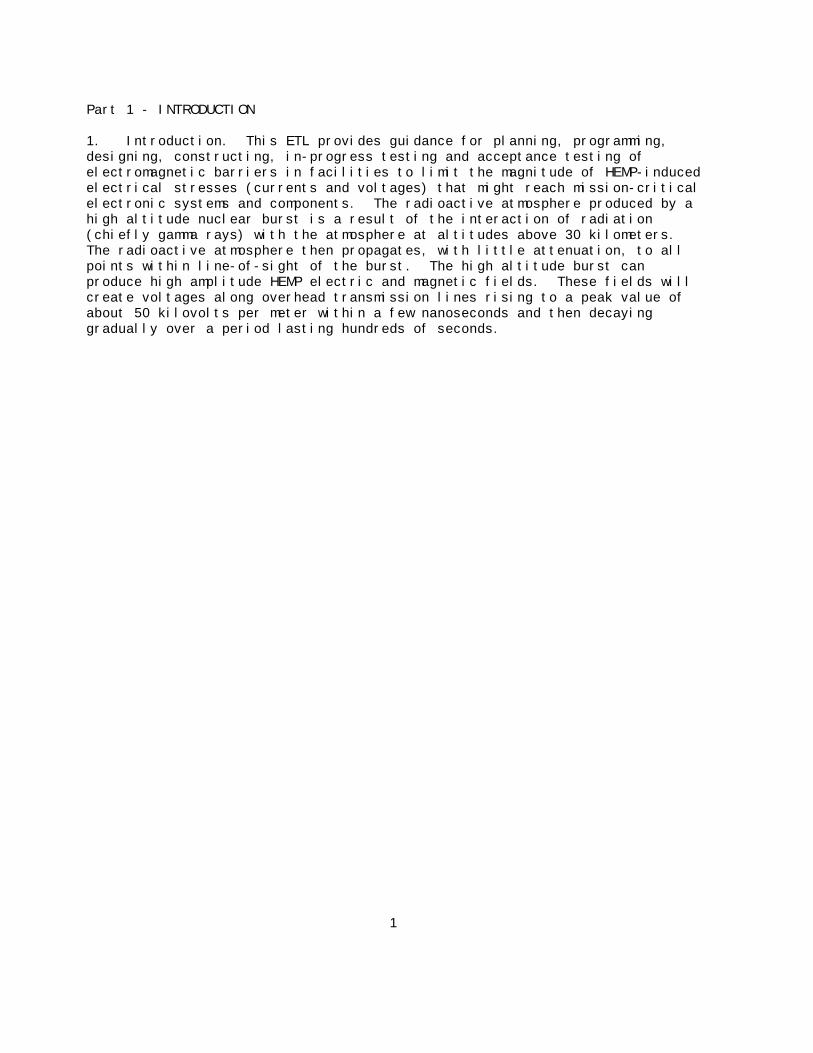
1. Introduction. This ETL provides guidance for planning, programming,designing, constructing, in-progress testing and acceptance testing ofelectromagnetic barriers in facilities to limit the magnitude of HEMP-inducedelectrical stresses (currents and voltages) that might reach mission-criticalelectronic systems and components. The radioactive atmosphere produced by ahigh altitude nuclear burst is a result of the interaction of radiation(chiefly gamma rays) with the atmosphere at altitudes above 30 kilometers. The radioactive atmosphere then propagates, with little attenuation, to allpoints within line-of-sight of the burst. The high altitude burst canproduce high amplitude HEMP electric and magnetic fields. These fields willcreate voltages along overhead transmission lines rising to a peak value ofabout 50 kilovolts per meter within a few nanoseconds and then decayinggradually over a period lasting hundreds of seconds.
1
Part 2 - General
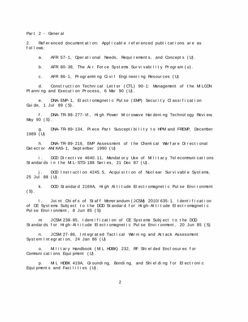
2. Referenced documentation: Applicable referenced publications are asfollows:
a. AFR 57-1, Operational Needs, Requirements, and Concepts (U).
b. AFR 80-38, The Air Force Systems Survivability Program (u).
c. AFR 86-1, Programming Civil Engineering Resources (U)
d. Construction Technical Letter (CTL) 90-1: Management of the MILCONPlanning and Execution Process, 6 Mar 90 (U).
e. DNA-EMP-1, Electromagnetic Pulse (EMP) Security ClassificationGuide, 1 Jul 89 (S).
f. DNA-TR-88-277-VI, High Power Microwave Hardening Technology Review,May 90 (S).
g. DNA-TR-89-134, Piece Part Susceptibility to HPM and FREMP, December1989 (U)
h. DNA-TR-89-216, EMP Assessment of the Chemical Warfare DirectionalDetector AN/KAS-1, September 1990 (U)
i. DOD Directive 4640.11, Mandatory Use of Military TelecommunicationsStandards in the MIL-STD-188 Series, 21 Dec 87 (U).
j. DOD Instruction 4245.5, Acquisition of Nuclear Survivable Systems,25 Jul 88 (U).
k. DOD Standard 2169A, High Altitude Electromagnetic Pulse Environment(S).
l. Joint Chiefs of Staff Memorandum (JCSM) 2010/635-1, Identificationof CE Systems Subject to the DOD Standard for High-Altitude ElectromagneticPulse Environment, 8 Jun 85 (S)
m. JCSM 238-85, Identification of CE Systems Subject to the DODStandards for High-Altitude Electromagnetic Pulse Environment, 20 Jun 85 (S)
n. JCSM 27-86, Integrated Tactical Warning and Attack AssessmentSystem Integration, 24 Jan 86 (U)
o. Military Handbook (MIL HDBK) 232, RF Shielded Enclosures forCommunications Equipment (U).
p. MIL HDBK 419A, Grounding, Bonding, and Shielding for ElectronicEquipments and Facilities (U).
2

q. Military Standard (MIL STD) 22D, Notice 2, Welded Joint Design (U).
r. MIL STD 188-124B, Grounding, Bonding, and Shielding (U).
s. MIL STD 188-125, High-Altitude Electromagnetic Pulse (HEMP)Protection for Ground-Based C4I Facilities Performing Critical, Time-UrgentMissions (U).
t. MIL STD 220A, Notice 1, Method of Insertion-Loss Measurement, 8 Mar78 (U).
u. MIL STD 248C, Notice 1, Welding and Brazing Procedure andPerformance Qualifications, 23 Jul 84 (U).
v. MIL STD 285, Attenuation Measurements for Enclosures,Electromagnetic Shielding, for Enclosures, Electromagnetic Shielding forElectronic Test Purposes, Method of (U).
w. MIL-STD-461C, Notice 2, Electromagnetic Emission and SusceptibilityRequirements for the Control of Electromagnetic Interference (U).
x. USAF Guide Specification for HEMP/TEMPEST Shield Doors, ElectricalFilter/ESA Assemblies, and other Shield Penetrations, June 1988 (U).
y. USAF Handbook for the Design and Construction of HEMP-Hardened POLFacilities, Nov 89, Revision 1, Jan 90 (U).
z. USAF Handbook for the Design and Construction of HEMP/TEMPESTShielded Facilities, Revision 2, Nov 89 (U).
3
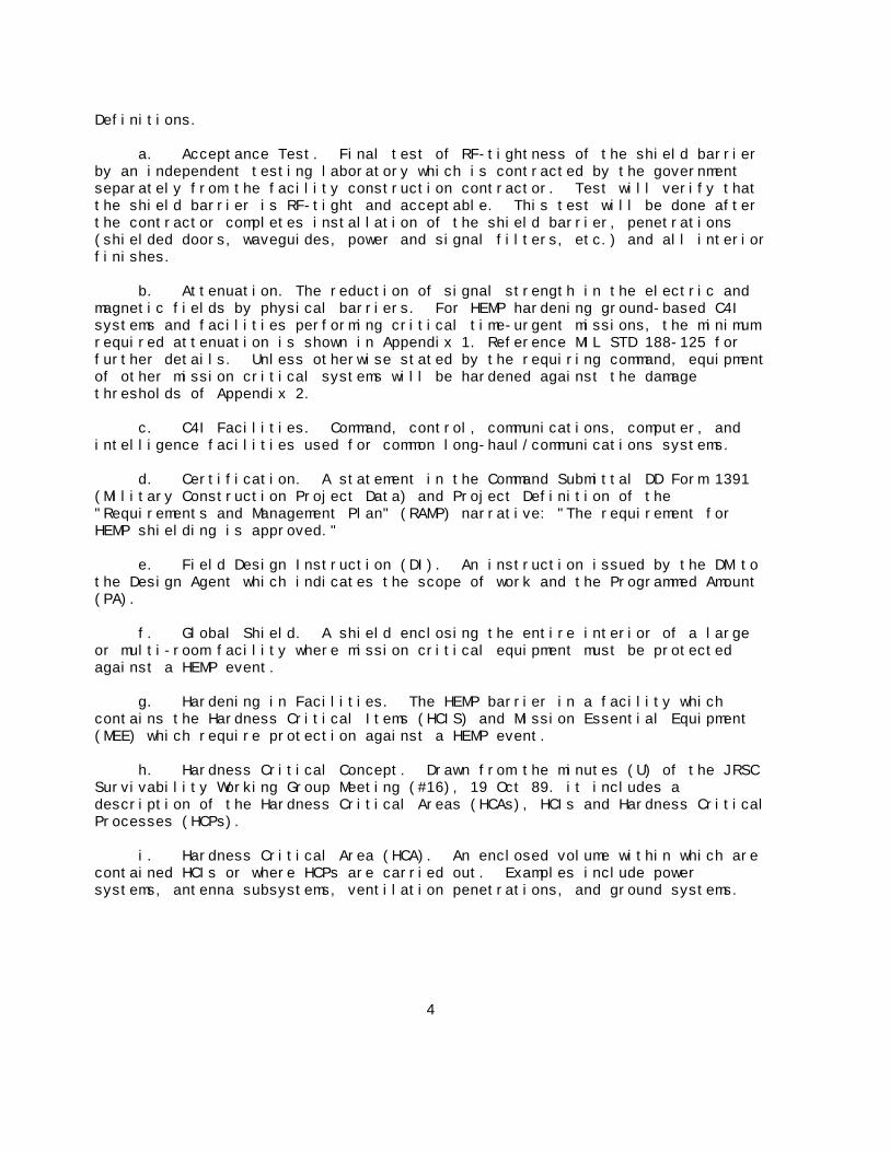
Definitions.
a. Acceptance Test. Final test of RF-tightness of the shield barrierby an independent testing laboratory which is contracted by the governmentseparately from the facility construction contractor. Test will verify thatthe shield barrier is RF-tight and acceptable. This test will be done afterthe contractor completes installation of the shield barrier, penetrations(shielded doors, waveguides, power and signal filters, etc.) and all interiorfinishes.
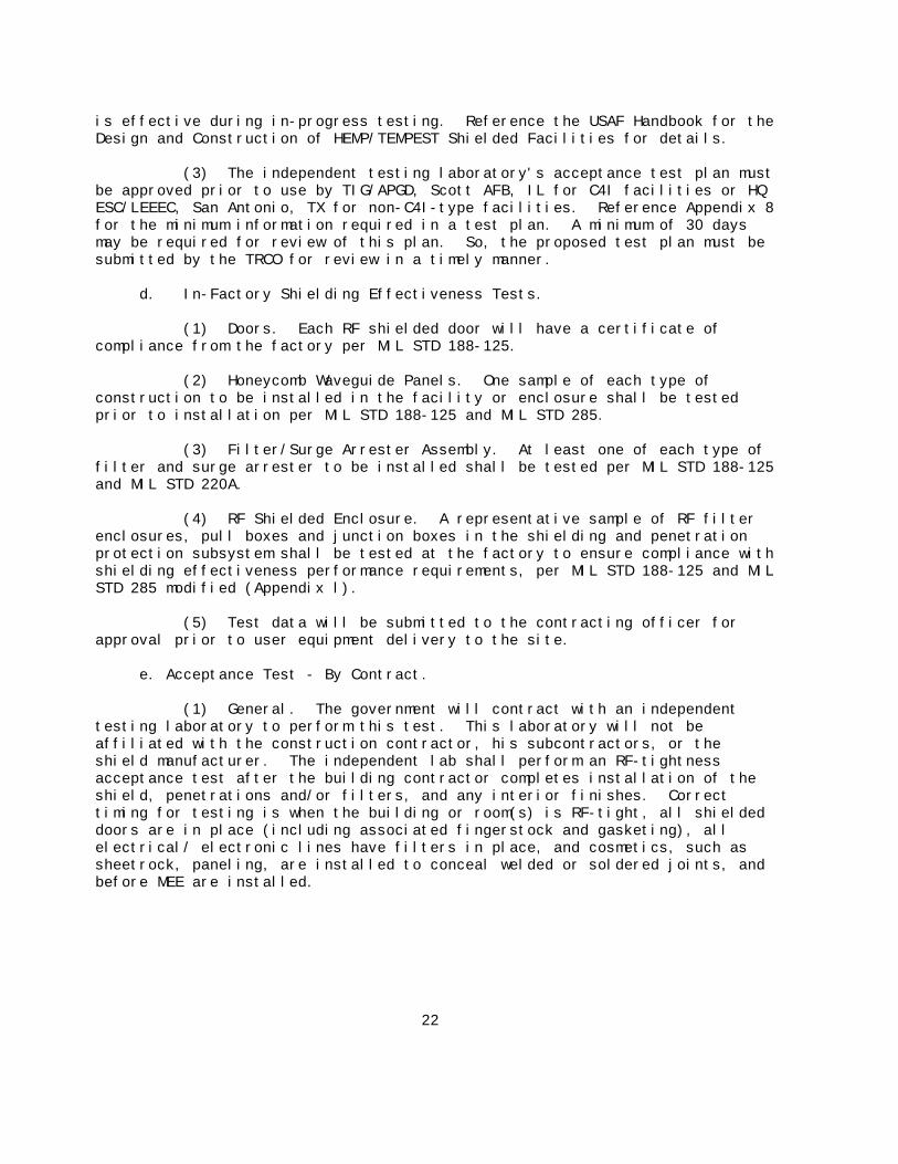
b. Attenuation. The reduction of signal strength in the electric andmagnetic fields by physical barriers. For HEMP hardening ground-based C4Isystems and facilities performing critical time-urgent missions, the minimumrequired attenuation is shown in Appendix 1. Reference MIL STD 188-125 forfurther details. Unless otherwise stated by the requiring command, equipmentof other mission critical systems will be hardened against the damagethresholds of Appendix 2.
c. C4I Facilities. Command, control, communications, computer, andintelligence facilities used for common long-haul/communications systems.
d. Certification. A statement in the Command Submittal DD Form 1391(Military Construction Project Data) and Project Definition of the"Requirements and Management Plan" (RAMP) narrative: "The requirement forHEMP shielding is approved."
e. Field Design Instruction (DI). An instruction issued by the DM tothe Design Agent which indicates the scope of work and the Programmed Amount(PA).
f. Global Shield. A shield enclosing the entire interior of a largeor multi-room facility where mission critical equipment must be protectedagainst a HEMP event.
g. Hardening in Facilities. The HEMP barrier in a facility whichcontains the Hardness Critical Items (HCIS) and Mission Essential Equipment(MEE) which require protection against a HEMP event.
h. Hardness Critical Concept. Drawn from the minutes (U) of the JRSCSurvivability Working Group Meeting (#16), 19 Oct 89. it includes adescription of the Hardness Critical Areas (HCAs), HCIs and Hardness CriticalProcesses (HCPs).
i. Hardness Critical Area (HCA). An enclosed volume within which arecontained HCIs or where HCPs are carried out. Examples include powersystems, antenna subsystems, ventilation penetrations, and ground systems.
4

j. Hardness Critical Items (HCIs). Those components and/orconstruction features which singularly and collectively provide specifiedlevels of HEMP protection, such as the RF shield, surge arrestors, RFshielded doors, shield welding, electrical filters, honeycomb waveguides, andwaveguides-below-cutoff.
k. Hardness Critical Processes (HCPs). Those installation, retrofit,and/or maintenance procedures which are applied to HCIs to implement HEMPprotection characteristics as designed.
l. HEMP. Acronym for "high-altitude electromagnetic pulse." Thispulse creates electrical transients which damage electronic equipment unlessthe equipment is protected.
m. HEMP Manager. The user of the hardened facility at the base levelor the requiring command representative who determines whether the equipmentor system needs to be HEMP hardened.
n. HEMP POC. The base civil engineer point of contact knowledgeableon HEMP hardening technical requirements.
o. HEMP OPR. The MAJCOM facilities engineer or Design Manager (DM)responsible for the successful design, construction and testing of HEMPbarriers in facilities. Reference Appendix 3 for a listing of HEMP shieldingcontacts.
p. Independent Testing Laboratory. A testing firm separate from theconstruction contractor contracted by the government, to conduct theacceptance test.
q. In-Progress Tests. Tests performed by the contractor during theinstallation/welding of the shielding before room finishes are installed. These tests are usually performed when the contractor seeks assurance thatthe shield joints and penetrations are not leaking RF, and the shieldedenclosure or facility is ready for the final acceptance test.
r. Mission Essential Equipment (MEE). Includes all equipment,sensitive and non-sensitive, necessary for survival and success of themission within the barrier.
s. Non-C4I Facilities. Mission critical facilities other thanC4I-type which must be operational after a HEMP event. These vary fromcommand to command and base to base and can be aircraft refueling facilities,hospitals, fire stations (systems), security police systems, airfieldlighting systems, etc.
t. Planning Instruction (PI). Authorization issued through theProgramming, Design and Construction system (PDC) by HQ USAF/CEC/CEP allowingthe Air Force Design Manager (DM) to proceed to 100 percent design at thediscretion of the requiring MAJCOM.
5
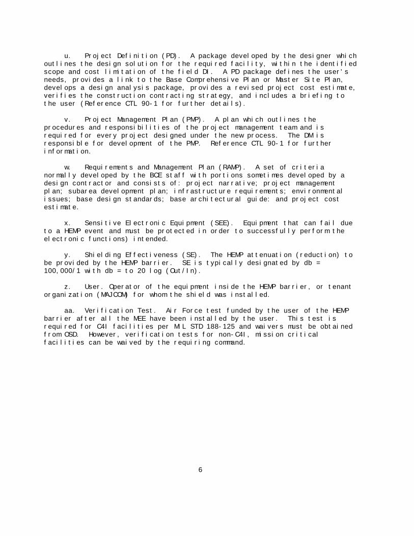
u. Project Definition (PD). A package developed by the designer whichoutlines the design solution for the required facility, within the identifiedscope and cost limitation of the field DI. A PD package defines the user'sneeds, provides a link to the Base Comprehensive Plan or Master Site Plan,develops a design analysis package, provides a revised project cost estimate,verifies the construction contracting strategy, and includes a briefing tothe user (Reference CTL 90-1 for further details).
v. Project Management Plan (PMP). A plan which outlines theprocedures and responsibilities of the project management team and isrequired for every project designed under the new process. The DM isresponsible for development of the PMP. Reference CTL 90-1 for furtherinformation.
w. Requirements and Management Plan (RAMP). A set of criterianormally developed by the BCE staff with portions sometimes developed by adesign contractor and consists of: project narrative; project managementplan; subarea development plan; infrastructure requirements; environmentalissues; base design standards; base architectural guide: and project costestimate.
x. Sensitive Electronic Equipment (SEE). Equipment that can fail dueto a HEMP event and must be protected in order to successfully perform theelectronic functions) intended.
y. Shielding Effectiveness (SE). The HEMP attenuation (reduction) tobe provided by the HEMP barrier. SE is typically designated by db =100,000/1 with db = to 20 log (Out/In).
z. User. Operator of the equipment inside the HEMP barrier, or tenantorganization (MAJCOM) for whom the shield was installed.
aa. Verification Test. Air Force test funded by the user of the HEMPbarrier after all the MEE have been installed by the user. This test isrequired for C4I facilities per MIL STD 188-125 and waivers must be obtainedfrom OSD. However, verification tests for non-C4I, mission criticalfacilities can be waived by the requiring command.
6
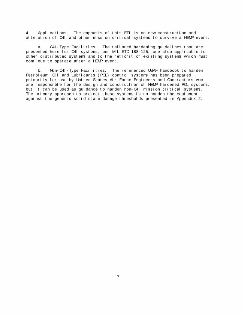
4. Applications. The emphasis of this ETL is on new construction andalteration of C4I and other mission critical systems to survive a HEMP event.
a. C4I-Type Facilities. The tailored hardening guidelines that arepresented here for C4I systems, per MIL STD 188-125, are also applicable toother distributed systems and to the retrofit of existing systems which mustcontinue to operate after a HEMP event.
b. Non-C4I-Type Facilities. The referenced USAF handbook to hardenPetroleum, Oil and Lubricants (POL) control systems has been preparedprimarily for use by United States Air Force Engineers and Contractors whoare responsible for the design and construction of HEMP hardened POL systems,but it can be used as guidance to harden non-C4I mission critical systems. The primary approach to protect these systems is to harden the equipmentagainst the generic solid state damage thresholds presented in Appendix 2.
7

Part 3 - HEMP HARDENING
5. Implementation - General. A major goal of HEMP protection is to assurethat validated requirements are satisfied with the most effective life cyclecost protection per AFR 80-38. Global shielding may not be required if theMEE/SEE are HEMP hardened at the equipment level and are properly integrated. However, for C4I-type facilities, MIL STD 188-125 requires global shieldingregardless of the life cycle cost. Hardening non-C4I, mission criticalsystems do not have to meet the requirements of MIL STD 188-125. Life cyclecost versus risk must be weighed. However, if HEMP hardening of non-C4Isystems electronic components is selected versus global shielding, theequipment must be able to withstand damage thresholds per Appendix 2. WhileC4I-type facilities are shielded from upset, non-C4I mission critical systemsshould be able to suffer upset and be reset within minutes to continuefunctioning.
a. C4I-Type Facilities. Hardening of systems in these types offacilities must be done IAW MIL STD 188-125. This is a fixed approach ofhigh first cost, low risk and high life cycle cost. Reference the USAFHandbook for the Design and Construction of HEMP/TEMPEST Shielded Facilitiesfor details.
b. Aircraft Refueling Facilities. Reference the USAF handbook forhardening POL systems.
(1) General. The POL systems have fewer sensitive electroniccomponents and less time sensitive operations. The trade-offs of cost andsurvivability should be considered.
(2) Microprocessors. The most reasonable and effective protectionis to HEMP harden the microprocessors or integrated circuitry associated-withthe electrical power and control to avoid the damage levels shown on Appendix2. The components must be protected if their inoperability will disable theoperation of the POL facility.
(3) Motors and Backup Generators. Hardening sensitive electroniccomponents also applies to backup generators which have electronics controls. Motors may be robust and not need protection, but their starting circuits mayhave solid state components.
(4) Preferred Consideration. The first consideration is to hardenthe pump control panel which contains microprocessors by installing filters,gaskets and/or waveguides on the cabinets and housings themselves, per theUSAF handbook to harden POL systems. This includes hardening SEE associatedwith the backup generators. This is a high risk but low life cycle costapproach. Reference Appendix 2 for damage levels of components.
8

(5) Alternate Approach. Another approach is to harden the controlroom which contains the SEE by installing global shielding. This is the lowrisk, high first cost and high life cycle cost.
c. Non-C41 Mission Critical Facilities. The approach will be similarto that for POL systems as described in paragraph b above.
(1) Harden equipment which houses sensitive electronic components. This is the low first cost, high risk, but low life cycle cost approach. Reference Appendix 2 for component damage levels.
(2) Install a shield barrier in part of the facility where the SEEis consolidated.
9
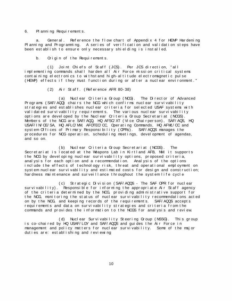
6. Planning Requirements.
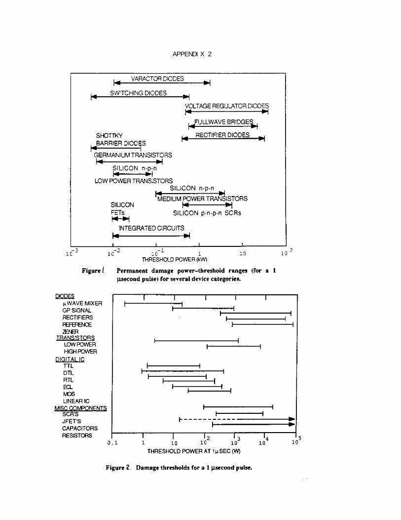
a. General. Reference the flow chart of Appendix 4 for HEMP HardeningPlanning and Programming. A series of verification and validation steps havebeen establish to ensure only necessary shielding is installed.
b. Origin of the Requirements.
(1) Joint Chiefs of Staff (JCS). Per JCS direction, "allimplementing commands shall harden all Air Force mission critical systemscontaining electronics to withstand high-altitude electromagnetic pulse(HEMP) effects if they must function during or after a nuclear environment."
(2) Air Staff. (Reference AFR 80-38)
(a) Nuclear Criteria Group (NCG). The Director of AdvancedPrograms (SAF/AQQ) chairs the NCG which confirms nuclear survivabilitystrategies and establishes nuclear criteria for selected USAF systems withvalidated survivability requirements. The various nuclear survivabilityoptions are developed by the Nuclear Criteria Group Secretariat (NCGS). Members of the NCG are SAF/AQQ, HQ AFSC/XT (Vice Chairperson), SAF/AQS, HQUSAF/IN/CE/SA, HQ AFLC/MM, AFOTEC/CC, Operating Commands, HQ AFWL/CC andsystem Offices of Primary Responsibility (OPRs). SAF/AQQS manages theprocedures for NCG operation, scheduling meetings, development of agendas,and so on.
(b) Nuclear Criteria Group Secretariat (NCGS). TheSecretariat is located at the Weapons Lab in Kirtland AFB, NM. it supportsthe NCG by developing nuclear survivability options, proposed criteria,analysis for each option and a recommendation. Analysis of the optionsinclude the effects of technology risk, threat and operational employment onsystem nuclear survivability and estimated costs for design and construction;hardness maintenance and surveillance throughout the system life cycle
(c) Strategic Division (SAF/AQQS - The SAF OPR for nuclearsurvivability). Responsible for informing the appropriate Air Staff agencyof the criteria determined by the NCG, providing administrative support forthe NCG, monitoring the status of nuclear survivability recommendations actedon by the NCG, and keeping records of the requirements. SAF/AQQS acceptsrequirements and data on survivability strategies and criteria from thecommands and provides the information to the NCGS for analysis and review.
(d) Nuclear Survivability Steering Group (NSSG). This groupis co-chaired by HQ USAF/LGY and SAF/AQQS and guides the Air Force inmanagement and policy matters for nuclear survivability. Some of the majorduties are: establishing and reviewing
10

requirements for nuclear survivability; developing goals for nuclearsurvivability activities; and establishing and documenting USAF policy/guidance for nuclear survivability. All MAJCOMs are represented in thisgroup.
(3) MAJCOM.
(a) The requiring command will establish HEMP hardeningrequirements per AFR 57-1.
(b) The requiring MAJCOM HEMP Manager must inform the user atthe base level of the hardening required.
(4) Base Level.
(a) HEMP Manager. The user should be involved in theplanning, programming, design reviews, site visits and barrier testing frominitial request to facility acceptance.
(b) For C4I-type systems, the user will submit an AF Form 332(BCE Work Request) to identify the requirement to construct a hardenedbarrier in a new or existing facility. For non-C4I-type systems, the usermust consider procuring hardened equipment first or hardening existingequipment per the damage thresholds 6f Appendix 2. If the equipment is realproperty installed equipment, then the user must submit an AF Form 332 tohave the work accomplished by the base civil engineer. The shielded barrieruser (HEMP Manager) and the Base HEMP POC should work together to determinethe HEMP hardening requirements for the new or renovated system.
(c) Construction Designation Code. A construction code willbe established by the Real Property Division (HQ USAF/CER) for the purpose ofidentifying those facilities or areas within a facility that are HEMPprotected.
(d) HEMP hardening requirements must be available at thePre-Project Definition Conference to avoid delays.
11
7. Programming Requirements for MILCON Funding.
a. General. Reference Appendix 4 for a planning and programming flowchart.
b. Command Submittal.
(1) The Base or Host MAJCOM HEMP OPRs must include a separate lineitem entitled "HEMP Hardening" under "Supporting Facilities" in Block 9 ofthe DD Form 1391.
(2) The following statement shall be included in the DD Form1391c: "The requirement for HEMP hardening is approved."
(3) The shielding cost estimate must be provided as a cost persquare foot of surface area and it includes filters, waveguides, shieldeddoors, etc., in addition to the metal shield plates.
(4) After the Air Staff Facilities Panel approves the scope of theproject, a PI will be issued by HQ USAF/CEC/CEP.
c. Funding. The cost for HEMP shielding will be programmed as follows:
(1) The acquisition cost for C4I facilities shielded per MIL STD188-125 is estimated to be $60 per Surface Square Foot (SSF) for shielding innew facilities, and $8O ($20 for demolition and $6O for installation of new)per SSF for installing shielding in existing facilities. These costestimates include a cost of $6.00 to $10.00 per SSF for testing, depending onthe size of the building. These costs are for the FY 92 program.
(2) The acquisition cost for non-C4I facilities shielded per USAFhandbook to harden POL systems is estimated to be $30 per SSF for shieldingin new facilities and $50 per SSF for installing shielding in existingfacilities. These estimates include a cost of $6.00 per SSF for testing.
(3) Shielding in new or existing facilities because of a missionchange will follow the appropriate funding guidance and thresholds formilitary construction or minor construction.
(4) Shielding new equipment (non-RPIE) will be user funded.
(5) Hardening existing RPIE SEE. Funding to harden existingequipment will be minor construction funds up to $200K. Above that, fundingrequest will be through the MILCON process. Efforts should be made toreplace this equipment with EAID and standardize with logistically supportedcomponents through AFLC.
12

(5) Hardening System Control Rooms in Existing Facilities. It maybe more cost effective to harden a room or part of a room than severalcabinets or housings which contain microprocessors. Funds for upgrading RPIEwill be minor construction up to $200K. Otherwise, the project will have tobe programmed for MILCON funding.
(6) Facility Alterations. Shielding which requires a permanentchange (removal of existing or construction of new fixed walls, roofs, etc)to an existing facility or a section of that facility because of a missionchange will follow the funding guidance and thresholds for militaryconstruction or minor construction appropriations.
(7) In-progress and acceptance tests will be funded as part of theconstruction project. However, the verification test by the Air Force, doneafter the contractor turns the facility over to the Air Force, is alwaysfunded by the user (requiring command).
8. Project Development (MILCON, FY92 and Beyond).
a. Planning Instructions (PIs). PIs issued by the Air Staff on HEMPhardening projects will be designated "Special Interest." This means that HQUSAF/CECE (Formerly AF/LEEDE) and/or HQ ESC/LEEEC should be notified of thepre-design and pre-construction conferences which they may attend.
b. Requirements and Management Plan (RAMP). Reference CTL 90-1, para4 for details.
c. Field Design Instruction. Include HEMP hardening as a specialinterest item. Reference CTL 90-1 for further details.
d. Project Management Plan (PMP). The project management team headedby the DM should consist of: the HEMP Manager; the HEMP Base POC; the HEMPOPRs from the host and requiring MAJCOMS: and the Design Agent's (DA's)project officer. Reference CTL 90-1 for further details.
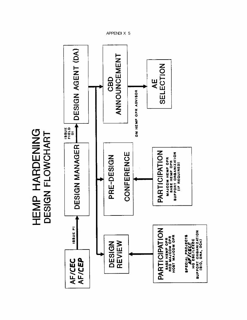
e. Commerce Business Daily (CBD) Announcements. The CBD announcementshould include the statement: "HEMP hardening design experience will be arating factor."
f. Architect-Engineer Firm (A-E) Selection. The DM HEMP OPR should beinvolved in the selection process. As a minimum, the OPR should act as anadvisor to the selection panel.
g. Pre-Project Definition Conference. For facilities or portions offacilities which will contain shielded areas of 1,000 SF or more, the HEMPBase POC, HEMP OPR from the Requiring MAJCOM and DM should attend theconference to ensure the A-E understands the requirements for shielding.
13

9. Design Requirements.
a. General. Reference Appendix 5 for a design flowchart.
b. Electromagnetic Barrier. Where a barrier is required, it must beconfigured to achieve the following technical objectives:
(1) Enclose all MEE which can practically be housed inside thebarrier.
(2) Minimize the number of shield POEs for interconnectionsbetween enclosed equipment and mission critical equipment outside thebarrier. Group POEs when possible.
(3) Minimize overall HEMP protection subsystem degradation due tofailure of a single HCI. HCIs should be standard, off-the-shelf items. Note: HCIs must be highlighted in the drawings and specifications.
c. C4I-Type Systems. For details, reference the USAF Handbook for theDesign and Construction of HEMP/TEMPEST Shielded Facilities. A copy of thishandbook can be obtained from HQ ESC/LEEEC or HQ USAF/CECE. Conflictsbetween the USAF handbook, guide specs or any others should be reportedthrough the DM or host MAJCOM to HQ USAF/CECE for resolution.
d. Non-C4I-Type Systems. These essential systems can be protected perUSAF handbook for design and construction of hardened POL systems. A copy ofthis handbook can be obtained from HQ USAF/CECE. Conflicts in criteria willbe handled as described in paragraph (c) above.
e. Levels of Protection.
(1) C4I-Type Systems. C4I facilities shall be tested and meet theshielding effectiveness requirements per Appendix 1.
(2) Non-C4I-Type Systems. A level of protection should besufficient to prevent the equipment from experiencing the damage threshold ofAppendix 2.
f. Shielding Material. The user determines that a shield barrier orglobal shield is cost effective. The designer will utilize materials of highpermeability, such as stainless or galvanized steel plates or sheets. Thesealso are corrosion resistant. Other materials, such as hypernick, mu-metalor permalloy, may be used if cost effective. Metallic foils must not be usedfor HEMP hardening. Reference the USAF handbook for design and constructionof shielded POL facilities for further details. Note: Bolted-type, sandwichpanels which have been proven life cycle cost effective may be considered.
14

g. Fire Alarm Systems.
(1) Global Shields. Filter-protected, communication-type circuitscan be used for fire reporting between the shielded facility and base firedepartment. However, fiber optics systems are preferred and should be usedwhere cost effective.
(2) Alarms for Shielded Areas within Buildings.
(a) Where alarm systems are hard-wired, consider installingan alarm panel inside the shielded area to receive signals from alarm headswithin the protected area. This will eliminate the need to penetrate theshield with large numbers of sensor wires, each of which must be filtered.
(b) Run two filtered signal lines or fiber optics cables fromthe panel in the shielded area to the building fire alarm panel. One linewill alert the fire department and occupants in the unshielded portion of thebuilding, while the other will alert the occupants in the shielded area of analarm outside the shielded area.
(c) The fire alarm equipment must be able to withstand thedamage and upset thresholds of Appendix 2.
(3) Sprinkler Piping in Waveguides. Care should be exercised bydesigners when locating lighting circuits, sprinkler piping, or anyconduit/piping systems within waveguide entryways. These systems can negatethe effectiveness of the waveguides if piping or conduit are not installedproperly. Reference the USAF handbook for Design and Construction ofHEMP/TEMPEST Shielded Facilities, page 150 for details.
h. High Voltage Filters. Avoid usage of filters greater than 600V. Step the voltage down if necessary in order to use lower voltage filters. Atpresent, high voltage filters are not reliable and can be safety hazards. Acquire Air Force standard filters with standard voltage and current ratingsthrough AFLC, when possible. If not available, use commercially availablefilters with standard voltages and current ratings. Recommend using lowestampacity size possible. Power filters leak reactive current to ground whichincreases power loss and lowers the power factor.
i. Shield Penetrations. Various items of mechanical equipment areoften located outside of the shielded enclosure. Note: Control wiring,pneumatic tubing, refrigerant lines, HVAC ducts and controls, etc., may needto be designed with adequate filtering/waveguides to attenuation RF signalsper this ETL. Reference the USAF handbook for HEMP/TEMPEST shieldingparagraph VI for details.
15
j. Shielded Equipment in Shielded Areas. Double filtering has beenknown to cause problems with Satellite Communications (SATCOM) earth terminalequipment, communication lines and with fire alarm and intrusion detectionsystems. Caution should be exercised with double filtering.
k. Solid State Systems in Non-C4I-Type Facilities. Sensitive circuitsystems such as microprocessor controls in aircraft refueling systems,airfield lighting control systems, standby generator controls, etc, require:
(1) Surge Protection. High speed (nanosecond reaction time) surgeprotection, such as a surge arrestor, must be placed on the input side of thetransformer, if it is to supply power only to the immediate SEE. If thepower system lines extend over 100 feet to the facility from the transformer,additional surge protection will be required at the motor control or powerdistribution center. The feeder must be in rigid conduit. Reference theGuide Specifications for HEMP/TEMPEST Shield Doors, Electrical Filter/ESAAssemblies, and other Shield Penetrations for further details.
(2) Metallic Conduit. All electrical wiring, i.e., betweenmotors, relays display panels, lights, sensors and power connections, shallbe shielded by metallic conduit which is electrically continuous andgrounded.
(a) Metallic rigid conduit must be used to contain all powerand control wires.
(b) All connections of conduit to boxes, conduit bodies,fittings, enclosures and shield shall be circumferentially welded.
(c) The conduit must be grounded to the building ground.
(3) Microprocessor Hardening. All sensitive electroniccomponents, such as the microprocessor in the power control panel, or thepower control panel itself shall be electromagnetically shielded against aHEMP event per Appendix 2, or must be placed in a hardened enclosure,whichever is most cost effective.
(4) Shielding. The shield shall consist of: RF-shielded wiringconduit; RF-tight equipment racks using RF gaskets; welded/brazed seals oncontainer seams; surge protection; and filters on electrical lines.
(5) Standby Generator. The generator control panel requiresshielding and the protection of electrical wiring. Special attention must begiven to the electronic components of the generator, such as the electronicgovernor.
16
l. Performance Specifications are Not Acceptable. Each design must becompletely detailed to leave no aspect to chance or guess work by theconstruction contractor. Detailed shop drawings of shieldingmaterial/component construction or installation must be reviewed and approvedby the Technical Representative for the Contracting Officer (TRCO).
m. Standardize Hardness Critical Items (HCI). Whenever possibleobtain standard products from AFLC (SM-ALC) which are stocklisted andlogistically supported items of equipment. This includes doors, electricalfilters, ventilation filters, latches, surge or transient suppressors,gaskets, etc.
n. Design Checklist. Appendix 6 is provided to assist the designersin preparing the drawings and specifications for the HEMP barrier.
o. Design Classification. The design will be unclassified to allownormal design and construction procedures.
p. Facility Testability.
(1) The HEMP barrier shall be accessible for visual inspection atall point-of-entries (utility penetrations and personnel entryways). Atleast one side of the shield, preferably the outside of the shield, must beeasily accessible to facilitate placing test equipment. Near penetrations,the exterior clearance must be 36 inches wide for safety purposes. Thisassumes the shielded volume is constructed within a building.
(2) A built-in shield monitoring capability should be installedwith the HEMP barrier, and include antenna loops, SELDS drive points (belowthe floor) or equivalent.
q. Design Reviews. The Base HEMP Manager and POC, host MAJCOM HEMPOPR and DM, and HQ ESC/LEEEC must be included in review at the 60 and 90percent design review stages. For C4I-type facilities, TechnologyIntegration Group (TIG)/APGD (formerly 1842 EEG) must be included in thereview process, and SIO/SYE for integrated TW/AA systems. HQ USAF/CECE mustbe included in the design reviews of shielded enclosures or facilities whichexceed 5,000 SSF scope.
17

10. Construction Requirements.
a. Preparation for Pre-Construction Conference. A contract whichincludes shielding requirements can be very complex. Therefore, allgovernment interested parties should meet prior to the Pre-ConstructionConference to review the shielding requirements and to resolve any questions.
b. Pre-Construction Conference. For shielding surface areas of 1,000SSF or more, the user, DM HEMP OPR or OPR's representative should attend thePre-Construction Conference. For shielded areas greater than 5,000 SSF, theuser and the DM HEMP OPR must attend the Conference, and the Base and MAJCOMHEMP OPRs should be invited. The OPRs must ensure that the contractor isaware of the special hardening requirements of the design and is capable ofcompleting them.
c. Welder/Installer Qualifications. An experience clause for the HEMPbarrier installer must be included in the design documents. The contractormust submit to the contracting officer certification that workers who are toweld and braze a facility HEMP shield are qualified to MIL STD 248. Weldingof thicker sheets should be done in accordance with the general provisions ofthe American Welding Society Standard Dl.1, which describes the proceduresfor welding carbon and low alloy steel greater than 1/8-inch thick.
(1) If the shield is to be welded, then the welder must becertified according to the applicable requirements of the American WeldingSociety. Shield welders must be qualified according to the weldingprocedures and welding operator performance using MIL-STD-248C and shallcomply with the Structural Welding Code of the American Welding Society forinert gas shielding metal arc welding. Where both structural integrity andshielding quality are required for a given weldment, both criteria shall bemet simultaneously. Where only welded joints are required, the welderqualification shall be based on an acceptable procedural qualification testper MIL-STD-22D.
(2) For soldering (limited to around the door fingerstock andother HCIS), the solderer must show previous experience in at least twosuccessful construction projects.
d. Inspector Qualifications. A HEMP-qualified construction inspectorshall inspect the progress of the 100 dB shielding and/or filteringinstallations. The inspector must be certified as an ElectromagneticCompatibility (EMC) Engineer or Technician by the National Association ofRadio and Telecommunications Engineers (NARTE) and be knowledgeable inshielding construction and practices. NARTE can be contacted at P.O. Box15029, Salem, Oregon 97309, or telephone (503) 581-3336.
18

e. Extended Warranties. HCIs are normally warranty to sustain theirattenuation above the required level, if maintained IAW the manufacturers'instructions. Requiring commands are encouraged to incorporate themaintenance and periodic testing of these components for the warranty periodas a portion of the contract. The following HCIs should be considered forextended warranties:
(1) All welds
(2) All power and signal filters
(3) All shielding doors (manufacturer provides maintenance kitincluding cheese cloth, putty knife, gaskets, finger stock, Allen wrenches,lubricants, etc., with each door)
(4) All honeycomb filters in mechanical systems and plumbing
(5) All waveguides
f. Submittals.
(1) All shielding submittals (shop drawings and literature fordoors, filters, etc.) shall be approved by the TRCO prior to installation. Any deviations from the shielding specifications and drawings must beapproved by the Contracting Officer (CO).
(2) Shop drawings of the contractor's proposed hardened equipmentand components must be reviewed by the TRCO with the assistance of Air ForceDM and MAJCOM HEMP OPR. These equipment and components are those boxes,filters, waveguides, i.e., hardness critical items which will be installedbetween the shielded and non-shielded areas.
(3) The contractor must submit a hardness maintenance/hardnesssurveillance plan for each HCI to ensure they are properly maintained and canprovide life cycle performance. The contractor shall submit a complete partslist, to include manufacturer and part number.
g. Construction Monitoring. The same MAJCOM HEMP OPR responsible formonitoring the design should also be responsible for monitoring the shieldinginstallation during construction. This is to ensure continuance not only ofknowledge of critical parts of the design, but also to ensure these areproperly installed during the construction. The following is a set oflessons learned during construction inspection.
(1) All penetrations (waveguides, welded pipes, and pipes betweenbuildings) into the HEMP barrier shall be tested and visually inspected forcorrosion and workmanship before finishes are installed.
19
(2) Properly fabricated and installed honeycomb waveguides forventilation ducts can be trouble-free. An example of a better method is anarray of one foot long metal pipes less than 1/2-inch diameter which arebonded together and which can also act as a waveguide for non-conductivematerials to provide attenuation per MIL STD 188-125. For further details,reference page 118, paragraph 5 of the USAF handbook to design and constructHEMP/TEMPEST shielded facilities.
(3) Installers will not install conductive material (wiring,sprinkler pipes, ducting, etc.) through waveguide penetrations because thiswill negate the frequency effectiveness of waveguides.
(4) Installation of shielded doors will be done by themanufacturer of the door or his representative. After acceptance testing,the building contractor should protect doors and finger stocks byconstructing a temporary protective structure around the shielded doors,while he continues to install the facility cosmetics. The doors will beprotected in-place and blocked open. Ramps will be placed over thethresholds. This is to ensure that the doors are not damaged by trafficduring installation of interior finishes.
h. Job Site Visits. The host and operating command HEMP OPRs or theirrepresentatives must visit the construction job site at the 35 percent and 65percent (as a minimum) of HEMP shielding construction to ensure thefacility's operating command is aware of the progress and intricacies of theconstruction. When the shielded facility has a shielded area 5,000 SSF orgreater, the CM should also invite HQ USAF/CECE and AFESC/DEMM to participatein the job site visits.
i. Conflicts and Discrepancies. HEMP hardening discrepancies, deficiencies, and conflicts that occur during construction must be documentedby the CM and resolved by the contracting officer in coordination with the CMand the MAJCOM HEMP OPP. Copies of these documents, along with the OPR'sresolutions and recommendations must be provided to HQ USAF/CECE.
20
11. Testing Requirements.
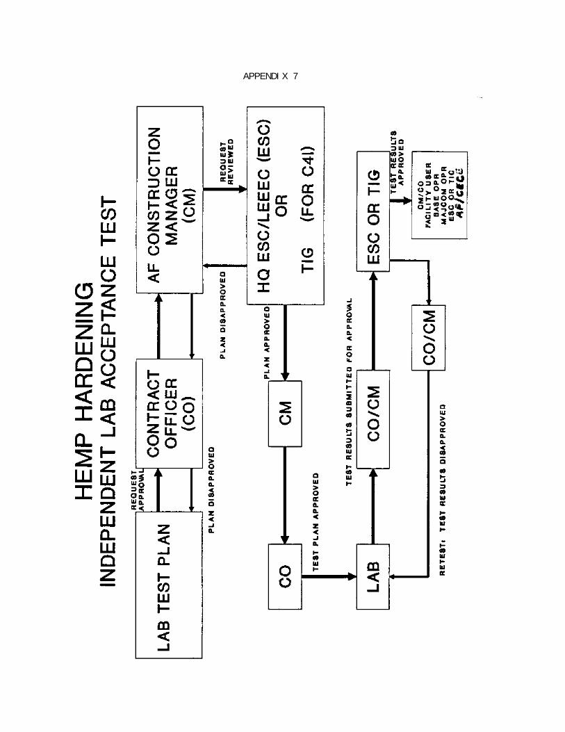
a. General. Shield testing has three main objectives: ensure goodmechanical and electrical joints, detect problems early so they can becorrected with minimum cost, and demonstrate spec compliance by thecontractor. Reference Appendix 8 for contractor test plan and resultsapproval flow chart (Appendix 7).
b. Security Classification. The results of a HEMP in-progress oracceptance test, whether pass or fail, are not classified. This assumes thefacility is not in operation. For C4I-type or non-C4I-type facilities,results of a verification test which indicate the facility has passed orfailed the verification test shall be classified and marked as to the samelevel of classification as the mission within the facility. This assumes thefacility is in operation. Reference DNA's EMP Security Classification Guide.
c. In-Progress Test by the Contractor. For shielded enclosures orfacilities with 5,000 SSF minimum shielded surface area, the contractorshould perform in-progress tests of seam, joint, and corner shield welds,door frame and honeycomb waveguides, panel frame welds to the primary shield,piping and conduit welds, and other welds in the shielding and points ofentry to assure himself that the expensive acceptance test will probablypass. For facilities with less than 5,000 SSF of shield area, greateremphasis must be given to in-factory testing of components and good qualityassurance.
(1) One hundred percent of the shield welds or soldered (primarilyaround doors and HCI penetrations) joints will be tested for RF radiationleaks as described below. The most common tests are non-destructive. Thecontractor can use the Shielded Enclosure Leak Detection System (SELDS) testor the dye penetrant test, or both.
(a) For welded steel, the dye penetrant procedure is thepreferred mechanical test technique.
(b) The shielded enclosure leak detection system (SELDS)testing evaluates the electromagnetic properties of the shield. This method,with recognition of its limitations, is also suitable for in-progress testingof incomplete shields. Reference the USAF Handbook for Design andConstruction of HEMP/TEMPEST Shielded Facilities for further details. Appendix 9 lists several testers which have been used in the past.
(2) SELDS testing entails direct-driving the shield with an RFcurrent, usually around 100 kHz. Joints are swept with a hand-held ferriteprobe that will detect RF energy leaking through the joints, either by directdiffusion or via. small holes. Although the SELDS test has limitations, it
21
is effective during in-progress testing. Reference the USAF Handbook for theDesign and Construction of HEMP/TEMPEST Shielded Facilities for details.
(3) The independent testing laboratory's acceptance test plan mustbe approved prior to use by TIG/APGD, Scott AFB, IL for C4I facilities or HQESC/LEEEC, San Antonio, TX for non-C4I-type facilities. Reference Appendix 8for the minimum information required in a test plan. A minimum of 30 daysmay be required for review of this plan. So, the proposed test plan must besubmitted by the TRCO for review in a timely manner.
d. In-Factory Shielding Effectiveness Tests.
(1) Doors. Each RF shielded door will have a certificate ofcompliance from the factory per MIL STD 188-125.
(2) Honeycomb Waveguide Panels. One sample of each type ofconstruction to be installed in the facility or enclosure shall be testedprior to installation per MIL STD 188-125 and MIL STD 285.
(3) Filter/Surge Arrester Assembly. At least one of each type offilter and surge arrester to be installed shall be tested per MIL STD 188-125and MIL STD 220A.
(4) RF Shielded Enclosure. A representative sample of RF filterenclosures, pull boxes and junction boxes in the shielding and penetrationprotection subsystem shall be tested at the factory to ensure compliance withshielding effectiveness performance requirements, per MIL STD 188-125 and MILSTD 285 modified (Appendix l).
(5) Test data will be submitted to the contracting officer forapproval prior to user equipment delivery to the site.
e. Acceptance Test - By Contract.
(1) General. The government will contract with an independenttesting laboratory to perform this test. This laboratory will not beaffiliated with the construction contractor, his subcontractors, or theshield manufacturer. The independent lab shall perform an RF-tightnessacceptance test after the building contractor completes installation of theshield, penetrations and/or filters, and any interior finishes. Correcttiming for testing is when the building or room(s) is RF-tight, all shieldeddoors are in place (including associated fingerstock and gasketing), allelectrical/ electronic lines have filters in place, and cosmetics, such assheetrock, paneling, are installed to conceal welded or soldered joints, andbefore MEE are installed.
22

(2) Purpose. This shield effectiveness test will inform thecontractor and the Air Force whether the shield installation is acceptable. As a minimum, a probe must be made for RF leaks at the shield joints,shielded doors, signal and power lines and other types of penetrations. Thetest can consist of a SELDS or equivalent test, and H-field and plane wave CWtests per MIL STD 188-125 and MIL STD 285. Reference the USAF Handbook forDesign and Construction of HEMP/TEMPEST Shielded Facilities for moredetails. Methodology and procedures for setting up equipment are per MIL STD285.
(3) Test Time. This test may range from only one to two weeks forsmall rooms to several months for large facilities. The government may savetime by fielding several independent testing teams. At some locations, thistest may have to be done at night, or weekends to avoid RF interference withother systems in the area.
(4) The building contractor must provide support to theindependent testing team. Generally, the testing team only tests. Thecontractor is responsible for correcting any deficiencies. The contractorwill have personnel available to immediately correct minor deficienciesuncovered by testing.
(5) Acceptance Test Plan Approval. Before the independent testinglab can use its test plan, it must be submitted for approval to the mLIG/APGDfor C4I-type facilities, or HQ ESC/LEEEC for all other types of facilities. This review could require a minimum of 30 days and must be submitted in atimely fashion by the CM to HQ ESC or TIC. Appendix 7 provides a listing ofminimum information required in a test plan.
(6) Qualified Independent Testing Laboratory. Qualified means thetesting firm has the expertise to perform shield testing per MIL STD 188-125and has a good track record (successfully tested four or five facilities withshielding surfaces of 1,000 SSF or greater) of testing shielded facilities orenclosures.
(7) Air Force Test Monitor.
(a) An Air Force HEMP OPR or his representative must bepresent during at least part of independent lab's testing to ensure it isbeing done according to the test plan. To effectively serve as the AirForce's representative during the acceptance test, the monitoring Air Forceagency must be included in the review cycle for the test plan.
(b) The 1839th EIG/EIX can be contacted through the EID/EIWto serve as the Air Force representative to monitor the independent testinglab's test. It is possible that a private consultant may have to be hired bythe operating command to perform this work if the workload at 1839th does notpermit them to be the Air Force representative.
23

(c) The monitoring team must work closely with thecontracting officer or his representative in the testing of the independenttesting laboratory and correction of deficiencies by the building contractor.
(d) The testing contractor shall maintain appropriate recordsto ensure that all welds are checked and results recorded. Allunsatisfactory welds shall be repaired by the building contractor andretested. Records shall be available for review by responsible Air Forceoffices. After the acceptance test, these records must be turned over to theuser or operating command.
(8) Independent Lab Test Result Approval. The test results mustbe submitted to TIC for C4I-type facilities or HQ ESC/LEEEC for all others toreview within 30 days after the test is performed. Copies of the testresults will also be provided to the construction contractor, user oroperating command, and the MAJCOM HEMP Manager.
(9) Test Failure.
(a) General. If the test indicates a shielding failure, thenthe building contractor will be responsible for making appropriate repairs tothe shield, and/or filtering components, and must pay for related retest.
(b) Cost for Retest. The building contractor payment forretesting by the independent testing laboratory will be based on the numberof points that failed divided by the total number of points tested. Thisfraction will then be multiplied times the total cost for testing the entirefacility.
(c) Time to Repair. Time allowances for time to repair ofshielding deficiencies by the contractor must be included in the facilityconstruction contract. The building contractor should be charged for delaysbeyond the allowed time for repairs. Historical information at the 1839thEIG/EIEE indicates that repairs can take from a few minutes (replace filters,door gaskets, etc.) to a few hours (removing finishes and re-welding) to oneyear (replacement of shielded door because it was the wrong type).
f. Verification Test (After Construction Completion) - By Air Force.
(1) General. For non-C4I-type facilities, the verification testis not required if no new penetrations are made after the equipment isinstalled and ready to run. However, for C4I-type facilities, theverification test is required per MIL STD 188-125. This test will be fundedby the user.
24

The test occurs after the Air Force has accepted the shielded enclosure orfacility from the building contractor. The user(s) or operating command(s)will contact EID/EIW (DSN 884-9386) at Tinker AFB to schedule testing of anyadditional penetrations and associated filters, waveguides, etc. EID tasksthe 1839th EIG/EIX (DSN 868-3920) at Keesler AFB to perform the tests. Ifthe 1839th cannot perform the test, then the user or operating command mayhave to contract with a private laboratory to perform this test.
g. Life-Cycle HEMP Hardening - For Warranty Considerations.
(1) Post Occupancy Testing. The user(s) will be responsible forHEMP surveillance of the shielding to ensure the integrity of the shield. Verification testing as described above will be funded by the user at leastonce every three years or whenever any structural change (alteration,addition, penetration, etc.) is made to the shielded enclosure or facility. The user should schedule more frequent testing every three months using RFillumination testing. While this test is not a comprehensive test, it doesindicate where shielding is leaking and needs repair and/or comprehensivetesting after the repair. Usual shielding leakage often occurs around thedoors, penetrations and along the corners of the shield sheets, or plates,and at the actual weld. AFLC is in the process of becoming the supportagency for Air Force hardness maintenance/hardness surveillance initiativesfor all HEMP barriers.
(2) Test Plan. The user must develop a verification test planwith the assistance of HQ ESC/LEEEC or TIC (for C4I-type facilities) forperiodic testing of critical facilities after beneficial occupancy of thefacility.
(a) Monthly Tests. This plan will consist of frequent visualinspections for shield cracks, corrosion along the shield, dirty fingerstock,and shield door malfunctions.
(b) Tri-Monthly Tests. This includes SELDS testing or usingthe built-in shield monitoring capability to identify leakage along shieldwelded joints and around the shielded doors.
(c) Three-Year Tests. These tests will be duplicates of theverification tests.
(3) Shielded Enclosure Test Set Included in the ConstructionContract. If the facility does not have a built-in shield monitoring system,then the contractor will turn over to the government a SELDS-type testersimilar to those described in Appendix 9. This tester should be the type usedduring the In-Progress testing. The tester will be maintained and operatedby the user.
25

(4) Correction of Deficiencies. The test team will not have thecapability to correct any deficiencies. The user must have a readilyavailable construction team to correct any deficiencies. Otherwise, thetesting team will be forced to make repeated trips to retest the facility orroom after the deficiencies have been corrected.
(5) Unlimited Access to the Facility. The test team (governmentor private contractor) must have unlimited access to the shielded facility orroom. Therefore its personnel must have adequate security clearances. Themission of the facility may have to be curtailed. Personnel door usage willbe very limited or even impossible during the testing.
(6) Testing Support. The test team (1839th or other governmenttesting agency) may need such things as scaffolding, and removal of anybuilding cosmetics to access the shield or penetrations and communicationsthrough shielded walls. If a private test firm performs the testing, it willprovide its own supporting equipment. Removal and replacement of thebuilding cosmetics is the responsibility of the user.
26

APPENDIX 1
APPENDIX 2

APPENDIX 2
2 of 2

APPENDIX 3
AIR FORCE HEMP HARDENING MAJCOM/AFRCE CONTACTS*****************************************************************************
ORGANIZATION NAME PHONE NUMBER
AAC/DEE Mr Alan Quesnel DSN 371-552-5187TIG/APGC Mr. Harlen Mayberry DSN 576-6121TIG/APGC Mr. Charles Ondrej DSN 576-6121TIG/APGD Mr. McKinnon DSN 576-3197AFLC/DEE Mr. Richard Winters DSN 787-4563AFLC/SCZPS Mr. Hank Miller DSN 787-7333AFRCE-ER Mr. Gary Lowe (404) 331-6566AFRCE-CR Mr. Cleo Walton (214) 653-3327AFRCE-WR Mr. Nick DiMario (415) 556-8326AFRCE-BMS/DEEC Mr. Eugene Shonka DSN 876-5615AFRES/DEE Mr. Bud Garner DSN 468-5755AFRES/DEM Mr. J. Hugh Maddox DSN 468-2903ATC/DEE Mr. A.G. Pinson DSN 487-2786ANGSC/DEE Mr. Fred MacDonald DSN 858-2461AFSC/DEE Mr. Jerry Lohsl DSN 858-6017MAC/DEM Mr. Sam Sivewright DSN 576-3067MAC/DEEE Mr. Rodney Hartleib DSN 576-5895SAC/DEER Mr. George Sachs DSN 271-4442SAC/DEMU Mr. Mark Bulechek DSN 271-5917AFSPACECOM/DEES Mr. Fred Loudon DSN 692-5030AFSPACECOM/LKNIP Maj Faudree DSN 692-5286SIO/SYE Mr. Richard Cullen DSN 692-5714PACAF/DEE Mr. Andy Hirano DSN 449-5120TAC/DESU Mr. Calvin Poole DSN 574-3237USAFA/DEE Mr. Ken Walters DSN 259-3460USAFE/DEE Mr. Romel Madlangbayan DSN 480-6795/6USAFE/DER Mr. Don Castamore DSN 232-4251USAFE/DER Mr. Joe Nicks DSN 230-4249AFFTC/DEEE Mr. Ron Smoldt DSN 527-8307SSD/DEE Mr. Peter Campbell DSN 833-0932AU/DEED Mr. Michael Allen DSN 875-6908ESD/DEE Mr. Charles Wire DSN 478-8604EID/EISS Mr. Robert Vaughan DSN 884-93871839th EIG/EIX Mr. Hugh Hanna DSN 597-3920TIG/APGD Mr. John Zych DSN 576-2661 or Mr Robert CarsonAFIT/DET Capt Brad Beer DSN 785-4552 or Capt Marc RichardASD/DEE Mr. Andrew Ernest DSN 785-5368HQ ESC/LEEE Mr. Joel Edwards DSN 945-2831AFESC/DEMM Mr. David Conkling DSN 523-6358AFESC/RDC Mr. Tom Hardy DSN 523-6315AF/CECE Mr. Refugio Fernandez DSN 297-4083AF/CECP Mr. Art Markowitz DSN 227-1235HQ DNA/RAEE LTC Clinton Gordon DSN 221-1158SAF/AQQS Lt. Col. Charles Martin DSN 223-6303WL/NTN Col John Justice DSN 244-0671
APPENDIX 4
APPENDIX 5

APPENDIX 6
DESIGNER'S CHECKLIST FOR THE RF SHIELD
1. Designer
a. Overview (1) Show shielding envelope by distinctive markings on thebuilding floor plan and elevation cross-section drawings. (2) Ensure that the design approach is constructible andmaintainable.
b. Drawings (1) Provide wall, floor and ceiling sections through each uniqueshield feature: (a) Seams between adjacent sheets (b) Wall-floor joints (c) Wall-ceiling joints (d) Wall-wall joints (e) Wall-wall-floor and -ceiling intersections (f) Anchoring details (g) Treatment of interior columns (h) Shield and false ceiling suspensions (i) Expansion joints (j) Other (2) Specify type and thickness of shield materials. (3) Specify methods of welding and type of welding materials. (4) Specify methods for protecting shield materials (emphasis ongaskets and associated sealer materials) from weather and unfavorableenvironmental factors.
c. Specifications (1) State shield performance requirements explicitly. (2) Include materials certifications (Emphasis on anti-corrosivecharateristics). (3) Include shop drawing requirements. (4) Include welder qualification and certification. (5) Specify maintenance procedure requirements. (6) Include quality assurance for: (a) In-progress weld testing (b) Complete shield test (c) Acceptance shielding effectiveness measurements (7) Determine if a shielding construction or quality assurancespecialist will be required by specifications (8) Extended warranties (optional)
2. Mechanical a. Overview (1) Identify all shield penetrations and ensure that each one isproperly protected. Group penetrations wherever possible. (2) Minimize penetrations by combining functions or making otherdesign changes.
1 of 3
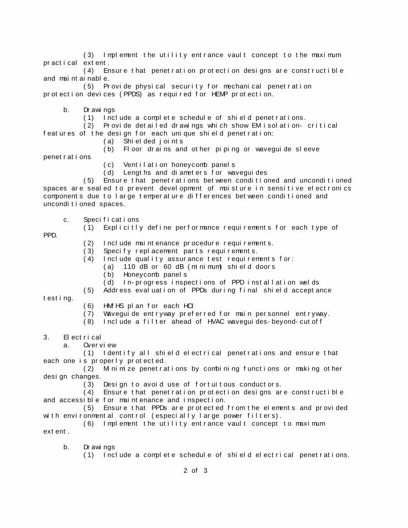
(3) Implement the utility entrance vault concept to the maximumpractical extent. (4) Ensure that penetration protection designs are constructibleand maintainable. (5) Provide physical security for mechanical penetrationprotection devices (PPDS) as required for HEMP protection.
b. Drawings (1) Include a complete schedule of shield penetrations. (2) Provide detailed drawings which show EM isolation- criticalfeatures of the design for each unique shield penetration: (a) Shielded joints (b) Floor drains and other piping or waveguide sleevepenetrations (c) Ventilation honeycomb panels (d) Lengths and diameters for waveguides (5) Ensure that penetrations between conditioned and unconditionedspaces are sealed to prevent development of moisture in sensitive electronicscomponents due to large temperature differences between conditioned andunconditioned spaces.
c. Specifications (1) Explicitly define performance requirements for each type ofPPD. (2) Include maintenance procedure requirements. (3) Specify replacement parts requirements. (4) Include quality assurance test requirements for: (a) 110 dB or 60 dB (minimum) shield doors (b) Honeycomb panels (d) In-progress inspections of PPD installation welds (5) Address evaluation of PPDs during final shield acceptancetesting. (6) HM/HS plan for each HCI (7) Waveguide entryway preferred for main personnel entryway. (8) Include a filter ahead of HVAC waveguides-beyond-cutoff
3. Electrical a. Overview (1) Identify all shield electrical penetrations and ensure thateach one is properly protected. (2) Minimize penetrations by combining functions or making otherdesign changes. (3) Design to avoid use of fortuitous conductors. (4) Ensure that penetration protection designs are constructibleand accessible for maintenance and inspection. (5) Ensure that PPDs are protected from the elements and providedwith environmental control (especially large power filters). (6) Implement the utility entrance vault concept to maximumextent.
b. Drawings (1) Include a complete schedule of shield electrical penetrations.
2 of 3
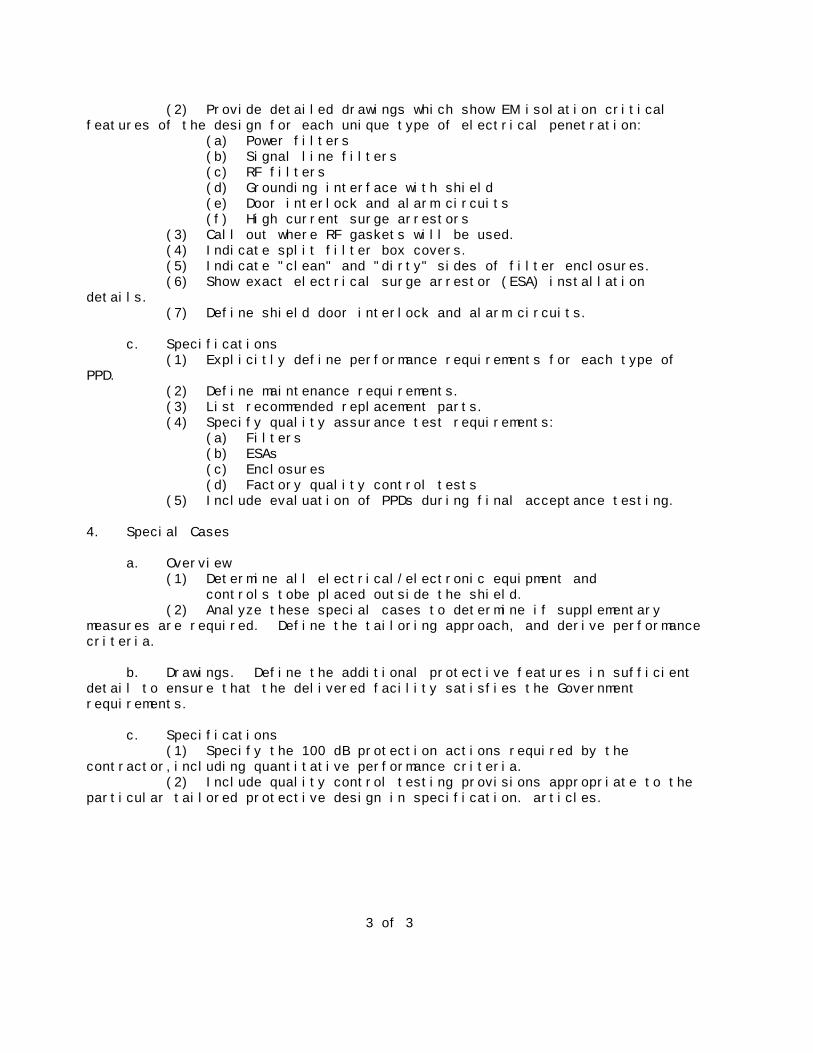
(2) Provide detailed drawings which show EM isolation criticalfeatures of the design for each unique type of electrical penetration: (a) Power filters (b) Signal line filters (c) RF filters (d) Grounding interface with shield (e) Door interlock and alarm circuits (f) High current surge arrestors (3) Call out where RF gaskets will be used. (4) Indicate split filter box covers. (5) Indicate "clean" and "dirty" sides of filter enclosures. (6) Show exact electrical surge arrestor (ESA) installationdetails. (7) Define shield door interlock and alarm circuits.
c. Specifications (1) Explicitly define performance requirements for each type ofPPD. (2) Define maintenance requirements. (3) List recommended replacement parts. (4) Specify quality assurance test requirements: (a) Filters (b) ESAs (c) Enclosures (d) Factory quality control tests (5) Include evaluation of PPDs during final acceptance testing.
4. Special Cases
a. Overview (1) Determine all electrical/electronic equipment and controls tobe placed outside the shield. (2) Analyze these special cases to determine if supplementarymeasures are required. Define the tailoring approach, and derive performancecriteria.
b. Drawings. Define the additional protective features in sufficientdetail to ensure that the delivered facility satisfies the Governmentrequirements.
c. Specifications (1) Specify the 100 dB protection actions required by thecontractor,including quantitative performance criteria. (2) Include quality control testing provisions appropriate to theparticular tailored protective design in specification. articles.
3 of 3
APPENDIX 7
APPENDIX 8
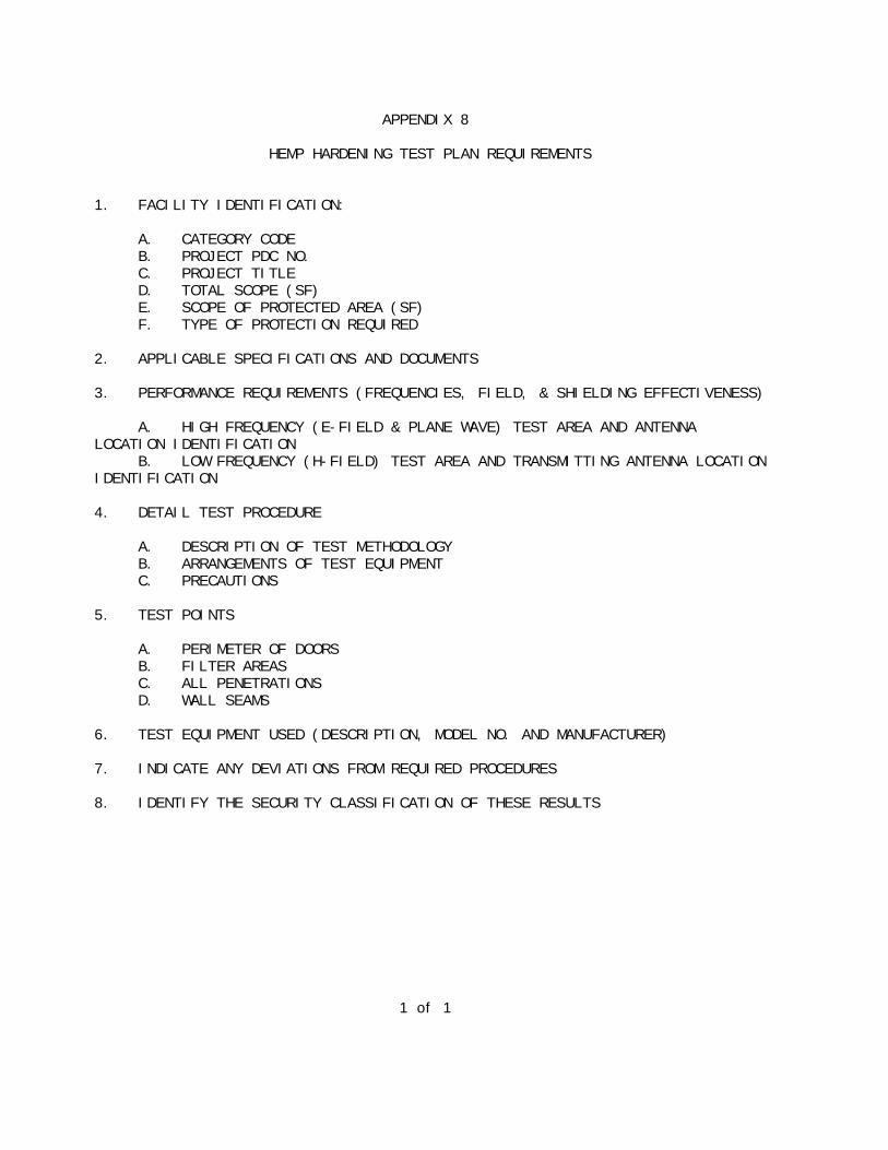
HEMP HARDENING TEST PLAN REQUIREMENTS
1. FACILITY IDENTIFICATION:
A. CATEGORY CODE B. PROJECT PDC NO. C. PROJECT TITLE D. TOTAL SCOPE (SF) E. SCOPE OF PROTECTED AREA (SF) F. TYPE OF PROTECTION REQUIRED
2. APPLICABLE SPECIFICATIONS AND DOCUMENTS
3. PERFORMANCE REQUIREMENTS (FREQUENCIES, FIELD, & SHIELDING EFFECTIVENESS)
A. HIGH FREQUENCY (E-FIELD & PLANE WAVE) TEST AREA AND ANTENNALOCATION IDENTIFICATION B. LOW FREQUENCY (H-FIELD) TEST AREA AND TRANSMITTING ANTENNA LOCATIONIDENTIFICATION
4. DETAIL TEST PROCEDURE
A. DESCRIPTION OF TEST METHODOLOGY B. ARRANGEMENTS OF TEST EQUIPMENT C. PRECAUTIONS
5. TEST POINTS
A. PERIMETER OF DOORS B. FILTER AREAS C. ALL PENETRATIONS D. WALL SEAMS
6. TEST EQUIPMENT USED (DESCRIPTION, MODEL NO. AND MANUFACTURER)
7. INDICATE ANY DEVIATIONS FROM REQUIRED PROCEDURES
8. IDENTIFY THE SECURITY CLASSIFICATION OF THESE RESULTS
1 of 1
APPENDIX 9
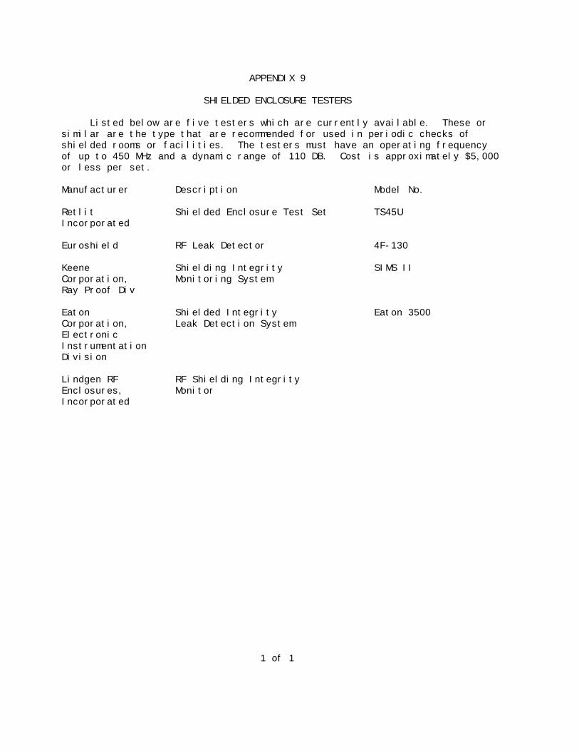
SHIELDED ENCLOSURE TESTERS
Listed below are five testers which are currently available. These orsimilar are the type that are recommended for used in periodic checks ofshielded rooms or facilities. The testers must have an operating frequencyof up to 450 MHz and a dynamic range of 110 DB. Cost is approximately $5,000or less per set.
Manufacturer Description Model No.
Retlit Shielded Enclosure Test Set TS45UIncorporated
Euroshield RF Leak Detector 4F-130
Keene Shielding Integrity SIMS IICorporation, Monitoring SystemRay Proof Div
Eaton Shielded Integrity Eaton 3500Corporation, Leak Detection SystemElectronicInstrumentationDivision
Lindgen RF RF Shielding IntegrityEnclosures, MonitorIncorporated
1 of 1
Index of 8 Feb 91
ENGINEERING TECHNICAL LETTERS (ETL)
SECTION A - CURRENT ETLs
ETL Number Title Date Issued
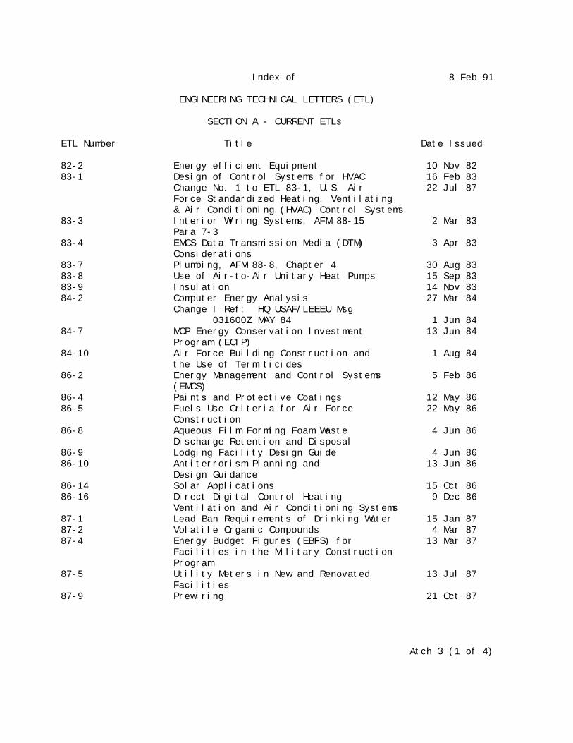
82-2 Energy efficient Equipment 10 Nov 8283-1 Design of Control Systems for HVAC 16 Feb 83 Change No. 1 to ETL 83-1, U.S. Air 22 Jul 87 Force Standardized Heating, Ventilating & Air Conditioning (HVAC) Control Systems83-3 Interior Wiring Systems, AFM 88-15 2 Mar 83 Para 7-383-4 EMCS Data Transmission Media (DTM) 3 Apr 83 Considerations83-7 Plumbing, AFM 88-8, Chapter 4 30 Aug 8383-8 Use of Air-to-Air Unitary Heat Pumps 15 Sep 8383-9 Insulation 14 Nov 8384-2 Computer Energy Analysis 27 Mar 84 Change I Ref: HQ USAF/LEEEU Msg 031600Z MAY 84 1 Jun 8484-7 MCP Energy Conservation Investment 13 Jun 84 Program (ECIP)84-10 Air Force Building Construction and 1 Aug 84 the Use of Termiticides86-2 Energy Management and Control Systems 5 Feb 86 (EMCS)86-4 Paints and Protective Coatings 12 May 8686-5 Fuels Use Criteria for Air Force 22 May 86 Construction86-8 Aqueous Film Forming Foam Waste 4 Jun 86 Discharge Retention and Disposal86-9 Lodging Facility Design Guide 4 Jun 8686-10 Antiterrorism Planning and 13 Jun 86 Design Guidance86-14 Solar Applications 15 Oct 8686-16 Direct Digital Control Heating 9 Dec 86 Ventilation and Air Conditioning Systems87-1 Lead Ban Requirements of Drinking Water 15 Jan 8787-2 Volatile Organic Compounds 4 Mar 8787-4 Energy Budget Figures (EBFS) for 13 Mar 87 Facilities in the Military Construction Program87-5 Utility Meters in New and Renovated 13 Jul 87 Facilities87-9 Prewiring 21 Oct 87
Atch 3 (1 of 4)

Index of 8 Feb 91
ENGINEERING TECHNICAL LETTERS (ETL)
SECTION A - CURRENT ETLs
ETL Number Title Date Issued
88-2 Photovoltaic Applications 21 Jan 8888-3 Design Standards for Critical Facilities 15 Jun 8888-4 Reliability & Maintainability (R&M) 24 Jun 88 Design Checklist88-5 Cathodic Protection 2 Aug 8888-6 Heat Distribution Systems Outside of 1 Aug 88 Buildings88-8 Cholorfluorocarbon (CFC) Limitation in 4 Oct 88 Heating, Ventilating and Air-Conditioning (HVAC) Systems88-9 Radon Reduction in New Facility 7 Oct 88 Construction88-10 Prewired Workstations Guide Specification 29 Dec 8889-2 Standard Guidelines for Submission of 23 May 89 Facility Operating and Maintenance Manuals89-3 Facility Fire Protection Criteria for 9 Jun 89 Electronic Equipment Installations89-4 Systems Furniture Guide Specification 6 Jul 8989-5 Not Used89-6 Power Conditioning and Continuation Interfacing Equipment (PCCIE) in the Military Construction Program (MCP) 7 Sep 8989-7 Design of Air Force Courtrooms 29 Sep 8990-1 Built-Up Roof (BUR) Repair/Replacement Guide Specification 23 Jan 9090-2 General Policy for Prewired Workstations and Systems Furniture 26 Jan 9090-3 TEMPEST Protection for Facilities Change I Ref: HQ USAF/LEEDE Ltr dated 20 April 90, Same Subject 20 Apr 9090-4 1990 Energy Prices and Discount Factors for Life-Cycle Cost Analysis 24 May 9090-5 Fuel and Lube Oil Bulk Storage Capacity for Emergency Generators 26 Jul 9090-6 Electrical System Grounding, Static Grounding and Lightning Protection 3 Oct 9090-7 Air Force Interior Design Policy 12 Oct 9090-8 Guide Specifications for Ethylene Propylene Diene Mononer (EPDM) Roofing 17 Oct 9090-9 Fire Protection Engineering Criteria for Aircraft Maintenance, Servicing, & Storage Facilities 2 Nov 9090-10 Commissioning of Heating, Ventilating and Air-Conditioning (HVAC) Systems Guide Specification 17 Oct 90
Atch 3 (2 of 4)
Index of 8 Feb 91
ENGINEERING TECHNICAL LETTERS (ETL)
SECTION A - CURRENT ETLs
ETL Number Title Date Issued
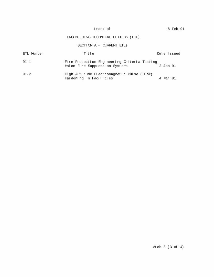
91-1 Fire Protection Engineering Criteria Testing Halon Fire Suppression Systems 2 Jan 91
91-2 High Altitude Electromagnetic Pulse (HEMP) Hardening in Facilities 4 Mar 91
Atch 3 (3 of 4)

8 Feb 91 SECTION B - OBSOLETE ETLs
No. Date Status
82-1 10 Nov 82 Superseded by ETL 83-10, 86-1, 87-482-3 10 Nov 82 Superseded by ETL 83-5, 84-282-4 10 Nov 82 Superseded by ETL 84-782-5 10 Nov 82 Superseded by ETL 84-1, 86-13, 86-1482-6 30 Dec 82 Cancelled82-7 30 Nov 82 Cancelled83-2 16 Feb 83 Superseded by ETL 84-383-6 24 May 83 Cancelled
84-3 21 Mar 84 Cancelled84-4 10 Apr 84 Superseded by ETL 86-7, 86-15, 87-584-5 7 May 84 Superseded by ETL 84-8, 86-11, 86-18, 88-684-6 Not Issued Cancelled/Not Used84-9 5 Jul 84 Superseded by ETL 88-786-3 21 Feb 86 Superseded by ETL 86-486-6 3 Jun 86 Superseded by ETL 86-11, 86-18, 88-686-7 3 Jun 86 Superseded by ETL 86-1586-12 3 Jul 86 Superseded by ETL 90-286-13 15 Aug 86 Superseded by ETL 86-1486-15 13 Nov 86 Superseded by ETL 87-586-17 17 Dec 86 Superseded by ETL 89-686-18 18 Dec 86 Superseded by ETL 88-687-3 12 Mar 87 Superseded by ETL 87-6, ETL 88-587-6 21 Aug 87 Superseded by ETL 88-587-7 14 Oct 87 Superseded by ETL 89-1Chg 1 30 Dec 87 Superseded by ETL 90-188-1 5 Jan 88 Superseded by ETL 89-288-7 24 Aug 88 Superseded by ETL 90-3 & ETL 91-289-1 6 Feb 89 Superseded by ETL 90-4
Atch 3 (4 of 4)