demonstration of a horseshoe-shaped longitudinal focal profile
TRANSCRIPT

Demonstration of a horseshoe-shaped longitudinalfocal profile
P. Brijesh
Laboratory for Laser Energetics and Department of Physics and Astronomy, University of Rochester,250 East River Road, Rochester, New York, 14623, USA
Terrance J. Kessler and Jonathan D. Zuegel
Laboratory for Laser Energetics, University of Rochester, 250 East River Road, Rochester, New York 14623, USA
David D. Meyerhofer
Laboratory for Laser Energetics, Department of Physics and Astronomy, and Department of Mechanical Engineering,University of Rochester, 250 East River Road, Rochester, New York, 14623, USA
Received October 31, 2006; accepted December 26, 2006;posted January 19, 2007 (Doc. ID 76544); published April 17, 2007
The three-dimensional laser focal region has been spatially shaped so that in the focal plane the transverseintensity distribution is centrally peaked, whereas at multiple defocused planes along the laser propagationdirection, the distribution is annular. The longitudinal profile of such a shaped laser focal volume is approxi-mately in the form of a “horseshoe.” The horseshoe-shaped longitudinal profile was realized experimentallyfrom a single laser beam by the incoherent coaxial combination of Laguerre–Gaussian and Gaussian modesgenerated from segmented optical elements. The ponderomotive forces associated with this three-dimensionalfocal-intensity distribution can potentially generate a quasi-collimated, forward-directed bunch of electronsfrom a low-density gas target at high laser intensities. © 2007 Optical Society of America
OCIS codes: 140.3300, 100.5090, 140.7010, 220.4830, 070.2580, 170.4520.
1. INTRODUCTIONThis article describes the generation of a horseshoe-shaped laser focus that can modify the angular distribu-tion of the electrons ponderomotively ejected from the fo-cal region. The dynamics of relativistic electrons in thefocus of a laser beam, neglecting collective effects, is gov-erned by the Newton–Lorentz equation
d
dt� mv�
�1 − v2/c2� = q�E� + v� � B��,
where E and B are the laser electric and magnetic fields,respectively; c is the speed of light; and v ,q, and m arethe electron velocity, charge, and rest mass, respectively.Time averaging the Newton–Lorentz equation leads to amodel, wherein the electron interaction with the externallaser field can be described by an interaction with an ef-fective, ponderomotive potential.1–5 The ponderomotivepotential �Up� is equivalent to the average quiver energyof the electron in the oscillating laser field and gives riseto the ponderomotive force1–6
F�p = − �Up = − mc2 � ��a2
2+ 1�1/2
− 1� ,
where the symbol � stands for spatial gradient. The di-mensionless parameter a is a measure of the normalizedoscillating momentum �posc/mc� of electrons quivering inthe laser field and is given by the relation7 a2=I�2 / �1.37
�1018�, where I is the laser intensity in W/cm2 and � isthe laser wavelength in micrometers. The ponderomotiveforce acts in a direction opposite to the spatial-intensitygradient, causing the electrons, generated by barrier-suppressed ionization of atoms,8,9 to be scattered out ofthe focal region with a maximum directed kinetic energyequal to the ponderomotive potential for linear polariza-tion and twice the ponderomotive potential for circularpolarization.10,11 For linearly polarized laser beams ofpeak intensity 2�1019 W/cm2 �a=3.9� and 1.053 �mwavelength, electrons generated at the peak of the laserfield are ponderomotively accelerated to a kinetic energyof about 1 MeV. For a Gaussian focus in the nonrelativis-tic regime, i.e., for peak intensity much less than1018 W/cm2 �a�1�, ponderomotive scattering leads toelectron ejection roughly perpendicular to the laser propa-gation direction. In the relativistic regime �a�1�, due tothe significant longitudinal component of the Lorentzforce q�v�B�, the electrons gain an additional longitudi-nal drift and are scattered into a forward cone of angle �(Fig. 1) given by10,11
tan � =� 2
� − 1,
where �−1=kinetic energy of the scattered elec-trons/mc2. For 1–MeV ��=3� electrons, this translatesinto a conical angle of about 45�. The inhomogeneity inthe spatial-intensity distribution of the Gaussian focus
1030 J. Opt. Soc. Am. B/Vol. 24, No. 5 /May 2007 Brijesh et al.
0740-3224/07/051030-7/$15.00 © 2007 Optical Society of America

coupled with the effect of high laser intensities leads tothe generation of a “diverging” electron bunch. Since thelaser focal profile governs the electron trajectories via theponderomotive force, a specially shaped laser focus offersa means toward controlling the dynamics of electrons gen-erated in the laser focal volume.
2. DESIGN GOALThe goal of this research is to design a spatially shapedlaser focus that can generate a quasi-collimated, forward-directed bunch of relativistic electrons. It is postulatedthat a laser focus with dual spatial characteristics—a cen-trally peaked, transverse focal-intensity distributiontransforming into an annular profile along the laserpropagation direction (Fig. 2)—can meet this objective.The longitudinal profile of such a shaped laser focus (in-tensity map as shown in Fig. 3) is characteristic of ahorseshoe. The spatial modification of the laser focus inthe far field is achieved by modulating the near-fieldphase of the laser beam using a phase plate.12 It is antici-pated that the ponderomotive forces associated with thecentrally peaked intensity region �z1�z�z2� of the horse-shoe focus (Fig. 3) will accelerate and inject electrons intothe radial potential well of the annular profile. The annu-lar intensity region �z2�z�z3� gives rise to a negative ra-dial gradient, leading to transverse focusing ofelectrons.13–17 The confinement of electrons closer to theaxis aids in the forward acceleration by longitudinal pon-deromotive forces since the electrons spend greater timeinteracting with the laser fields as compared with thecase of a pure Gaussian focus.18,19 Therefore the“concave”-shaped, three-dimensional ponderomotive po-tential associated with a horseshoe laser focus can accel-erate and focus the electrons in three dimensions more ef-fectively than a purely Gaussian focus. Since the three-dimensional focal volume conserves energy, the intensityand dimensions of the centrally peaked region of thehorseshoe focus are constrained by the characteristics ofthe annular profile and vice versa. Qualitatively, the rela-tive depth of focus of the central peak �d1 /D� has to bemuch less than or, at most, equal to that of the annularprofile �d2 /D�; otherwise, the focal volume would be madeprimarily of the central peak, leading to electrons beingscattered from the focal region without being affected bythe radial focusing effect of the annular profile. The ac-tual values for various system parameters, e.g., the rela-tive intensity �I�z2� /I�z1� ,I�z3� /I�z2�, relative depth of fo-cus �d1 /D ,d2 /D, angular divergence ��r ,z�, andcontrast of the annulus, will be determined by the elec-
tron dynamics in the electromagnetic fields of the shapedlaser focus. This paper will describe the design and dem-onstration of an optical element that generates a longitu-dinal focal profile approximately in the form of a horse-shoe. Future research will determine the actual values forvarious parameters of the shaped laser focus, which opti-mizes the acceleration and focusing of the laser-generatedelectrons.
3. OPTICAL SYSTEM DESIGNA. Conceptual DesignTo the first order, the desired horseshoe-shaped focal pro-file can be approximated as a combination of a Laguerre–Gaussian (doughnut) beam and a Gaussian beam with aslight axial focal offset between the two. The annular-shaped intensity distribution of the doughnut beam canbe generated from a Gaussian beam using a spiral phaseplate.20,21 The beam combination could be in either the in-tensity or the field domain, depending on the relative po-larizations. A representative horseshoe focal profile ob-tained by the intensity combination of the orthogonally
Fig. 2. Schematic transverse intensity profile of a horseshoe-shaped focus (profile is cylindrically symmetric about the z axis).
Fig. 3. Schematic longitudinal intensity map for a horseshoe-shaped focal profile (the profile is cylindrically symmetric aboutthe z axis).
Fig. 1. Scattering direction of electrons born in the laser field.11
Brijesh et al. Vol. 24, No. 5 /May 2007/J. Opt. Soc. Am. B 1031
polarized doughnut beam and the Gaussian beam isshown in Fig. 4. The coherent beam combination, i.e.,beam combination in the field domain, suffers from focal-spot distortion due to the interference between the spiralwavefront of the doughnut beam and the flat wavefront ofthe Gaussian beam.22–24 Inducing mutual incoherence be-tween the two beams solves the interference problem.This can be done by either combining two orthogonally po-larized beams or inducing spatial or temporal incoherencein one of the beams. A single-beam solution based on theformer approach using segmented optics25,26 is shown inFig. 5. The segmented wave plate is an annular substratewith a half-wave plate embedded in the central annulus.The segmented phase plate consists of a flat substratewith a spiral phase etched in the central region and aquadratic defocus phase in the outer annular region (Fig.6). The equations relating the axial defocus in the far fieldto the near-field defocus phase have been derived in Ap-pendix A. The half-wave plate rotates the polarization ofthe central region of an incident Gaussian beam by 90�
with respect to the outer region of the beam. The innerbeam is modulated by the spiral phase and gives rise tothe doughnut profile, while the outer beam generates thedefocused Gaussian profile. The inner and outer beamsare orthogonally polarized and hence lead to an incoher-ent coaxial combination in the far field.
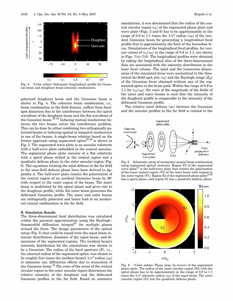
B. Simulation ResultsThe three-dimensional focal distribution was calculatedwithin the paraxial approximation using the Rayleigh–Sommerfeld diffraction integral27 for multiple planesaround the focus. The design parameters of the opticalsetup (Fig. 5) that could be tuned were the input beam in-tensity distribution, diameter of the input beam, and di-mensions of the segmented regions. The incident beam’sintensity distribution for the simulations was chosen tobe a Gaussian. The radius of the hard aperture �R�, i.e.,the external radius of the segmented optics, was chosen tobe roughly four times the incident beam’s 1/e2 radius �0�to minimize any diffraction effects due to truncation ofthe Gaussian beam.28 The ratio of the areas of the centralcircular region to the outer annular region determines therelative intensity of the doughnut and the defocusedGaussian profiles in the far field. Based on extensive
simulations, it was determined that the radius of the cen-tral circular region �c0� of the segmented phase plate andwave plate (Figs. 5 and 6) has to be approximately in therange of 0.9 to 1.1 times the 1/e2 radius �0� of the inci-dent Gaussian beam for generating a longitudinal focalprofile that is approximately the form of the horseshoe fo-cus. Simulations of the longitudinal focal profiles, for vari-ous values of �c0 /0� in the range of 0.9 to 1.1, are shownin Figs. 7(a)–7(d). The longitudinal profiles were obtainedby taking the longitudinal slice of the three-dimensionaldata set associated with the intensity distribution in thelaser focal volume. The axial and the transverse dimen-sions of the simulated focus were normalized to the theo-retical far-field spot size �f� and the Rayleigh range �ZR�of the Gaussian focus obtained without any of the seg-mented optics in the beam path. Within the range of 0.9 to1.1 for �c0 /0�, the ratio of the magnitude of the fields ofthe inner and outer beams is such that the intensity ofthe doughnut profile is comparable to the intensity of thedefocused Gaussian profile.
The relative axial defocus ��z� between the Gaussianand the annular profiles in the far field is related to the
Fig. 4. (Color online) Schematic longitudinal profile for Gauss-ian beam and doughnut beam intensity combination.
Fig. 5. Schematic setup of incoherent coaxial beam combinationusing segmented optical elements. Region P2 of the segmentedwave plate25 is the half-wave plate that rotates the polarizationof the inner central region (P2) of the laser beam with respect tothe outer region (P1). Region S2 of the segmented phase plate25,26
has a spiral phase, and region S1 has a quadratic defocus phase.
Fig. 6. (Color online) Phase map (in waves) of the segmentedphase plate. The radius of the inner circular region (S2) with thespiral phase has to be approximately in the range of 0.9 to 1.1times the 1/e2 intensity radius �0� of the input beam. The outerannular region (S1) has the quadratic defocus phase.
1032 J. Opt. Soc. Am. B/Vol. 24, No. 5 /May 2007 Brijesh et al.

near-field peak-to-valley defocus phase ��d� by the rela-tion �d��z� 2 /8��f# �2 [Eq. (A2) in Appendix A], where =R /0 is the ratio of the radius of the hard aperture �R�of the segmented optics to the input beam radius �0� andf# = f /20 is the ratio of the focal length �f� of the focusinglens to the input beam diameter. For the simulation re-sults shown in Figs. 7(a)–7(d), the axial defocus ��z� is ap-proximately 200 �m �1.7 ZR� for f# 12 and =4. Thecorresponding near-field peak-to-valley defocus phase��d� is approximately 4.5 �. If �c0 /0� is much less(greater) than the lower (upper) limit of the range of 0.9 to1.1, the intensity of the doughnut profile is much less(greater) than the intensity of the defocused Gaussianprofile in the far field. Simulations of the longitudinal fo-cal profile for �c0 /0� outside the range of 0.9 to 1.1 areshown in Figs. 7(e) and 7(f). Achieving the right intensitybalance between the defocused Gaussian profile and thedoughnut profile depends on the ratio of the magnitude ofthe fields incident on the inner and outer regions of thesegmented optics.
C. Optical LayoutA focal-spot characterization testbed consisting of acontinuous-wave HeNe laser, variable magnificationbeam expander system, segmented optical elements, fo-cusing lens, and a microscope objective attached to a digi-tal CCD (charge-coupled-device) camera was set up to testthe optical design (Fig. 8). The wavelength ��� of the laserwas 632 nm, the focal length �f� of the lens was 150 mm,the magnification of the microscope objective was 40�,
and the camera with a dynamic range of 12 bits had530�492 pixels across its 6.5 mm�4.9 mm aperture. Apolymer film polarizer with a clear aperture of 5 mm, lo-cated before the variable beam expander, sets the polar-ization of the incident laser beam. An iris with a variablediameter was placed before the segmented wave plate forblocking the laser propagating through the outer annularregion of the segmented optics. A second polarizer (notshown), located after the segmented wave plate, acts asan analyzer and is used to set the orientation of the half-wave plate. The segmented wave plate consisted of astandard multiorder quartz half-wave plate (12.7 mm di-ameter) held inside an annular BK7 substrate (50.8 mmexternal diameter) with a split brass ring of 330 �mthickness. The spiral phase element was custom fabri-cated by RPC Photonics29 in the central circular region of12.7 mm diameter on a fused-silica substrate with a50.8 mm external diameter (Fig. 8). The outer annular re-gion of the substrate was transparent and polished to apeak-to-valley wavefront quality of about � /10. The cen-tral spiral phase was qualified interferometrically using afrequency-shifting Fizeau interferometer. The surface re-lief map of the spiral phase, obtained from the phaseanalysis software of the interferometer, is shown in Fig. 9.The azimuthal variation of phase from 0 to 2� gives riseto a helical wavefront for the laser beam refracted fromthe spiral phase plate. Since the phase at the center of ahelical wavefront is undefined, the far-field intensity dis-
Fig. 8. (Color online) Focal-spot characterization testbed to testthe segmented optical design (Fig. 5) for generating the horse-shoe focus.
Fig. 7. (Color online) Simulation of longitudinal focal profilesgenerated by the segmented optical design of Fig. 5 for variousvalues of �c0 /0�: (a) 0.9, (b) 0.97, (c) 1.0, (d) 1.1, (e) 0.85, (f) 1.25.Theoretical Gaussian spot size �f�4.7 �m, and Rayleigh range�ZR�112 �m.
Fig. 9. (Color online) Surface-relief phase map of RPC Inc.’s spi-ral phase plate measured by the Fizeau frequency-shifting inter-ferometry. The measured peak-to-valley phase is 1.08 �.
Brijesh et al. Vol. 24, No. 5 /May 2007/J. Opt. Soc. Am. B 1033

tribution of the laser beam has a central null throughoutthe focal volume.30,31 For imprinting the defocus phase inthe outer annular region of the incident beam, a tunabledefocus phase system was implemented using a combina-tion of positive and negative annular lenses of equal focallength ��f0 � =500 mm� and separated by a variable air gap�d� (see Fig. 8). A zero separation gap between the twolenses leads to a zero net quadratic phase since the posi-tive and negative annular lenses have opposite power. Afinite separation gap between the two lenses leads to a fi-nite amount of quadratic defocus phase. By varying theseparation gap, the defocus phase in the outer annular re-gion of the incident laser beam can be tuned from zero.The central region of the laser beam propagates throughfree space and hence does not accumulate any defocusphase irrespective of the actual value of the separationgap. The magnitude of variable gap �d� is related to therelative axial defocus ��z� between the Gaussian and theannular profiles by the relation d�z�f 0
2 / f2� [Eq. (A5) inAppendix A], where f0 and f are the focal lengths of theannular lens and the final focusing lens, respectively. Forf0=500 mm, f=150 mm, and �z=200 �m, d2 mm. Oneof the annular lenses was mounted on a translation stageto enable the tuning of the variable gap �d�. A larger valueof gap �d� obtained by choosing a larger value of f0 is pref-erable since it is easier to align and tune the annular lenssystem with a larger separation between the two lenses.
4. EXPERIMENTAL DEMONSTRATIONThe HeNe laser beam was upcollimated by the variablebeam expander to a 1/e2 intensity diameter of approxi-mately 12.7 mm to match the diameter of the annulus ofthe segmented optics �c0 /01�. The initial steps in theexperiment involved making the outer beam orthogonallypolarized to the inner beam. For this purpose, only theanalyzer and the focusing lens were first inserted into thebeam path. The transmission axis of the analyzer wasaligned parallel to the polarization direction of the upcol-limated laser beam. The segmented wave plate was thenext element to be inserted into the beam path. The outerannular region of the segmented wave plate was blockedby the variable-diameter iris to allow only the central re-gion of the laser beam to propagate through the opticalsystem. The segmented wave plate was rotated to null thesignal emerging from the analyzer. This nulling is indica-tive of the fact that the polarization direction of the laseremerging from the half-wave plate is orthogonal to thetransmission axis of the analyzer. Since the transmissionaxis of the analyzer defines the polarization direction ofthe laser beam incident on the segmented wave plate, thisparticular orientation of the half-wave plate ensures thatthe inner central region of the laser beam is orthogonallypolarized to the outer annular region of the beam. Theanalyzer was then removed from the system, and the seg-mented phase plate was introduced into the beam path.The transverse focal profile was imaged by the microscopeobjective onto the CCD camera, and the segmented phaseplate was aligned to give the best doughnut profile. Thetunable defocus system was the next element to be in-serted into the beam path. The iris was opened fully to al-low the light from the outer region to propagate through
the system, and a stop was inserted into the central an-nulus of the segmented wave plate to block the light fromthe central region. The variable gap �d� and the align-ment of the annular lenses in the defocus system were ad-justed to give the best defocused Gaussian profile. Thecentral stop was then removed to allow the outer beam tocoaxially combine with the inner beam. By translatingthe objective and the camera along the laser propagationdirection, the transverse focal profiles were recorded atvarious axial positions extending from −500 to +500 �min steps of 50 �m. The transverse focal profiles of theshaped laser focus at z=0, 1.6 ZR, 3.2 ZR, and 4.8 ZR areshown in Fig. 10. The z=0 position represents the axiallocation of the best focus of the centrally peaked profile.The transverse and axial dimensions of the recorded datawere normalized to the spot size �f� and the Rayleighrange �ZR� of the experimental Gaussian focus obtainedwithout any of the segmented optics in the optical system.The asymmetries in the transverse profile are attributedpartly to the phase errors accumulated from the optics bythe laser beam. Moreover, the holes cored in the lenses ofthe tunable defocus element caused asymmetric corruga-tions at the inner edge. The diffraction from these irregu-lar edges also contributed to the asymmetries. Apodizingthe inner edges of all of the annular elements and usingoptics with better transmitted wavefront quality can miti-gate the circular asymmetries. Nevertheless, the focalprofiles in Fig. 10 clearly show that the centrally peakedtransverse profile transforms to an annular profile. Eachof the two-dimensional data sets recorded at the axial po-sitions within −500 to +500 �m were azimuthally aver-aged to generate the equivalent longitudinal profile (Fig.11) of the shaped laser focal volume. The relative axial de-
Fig. 10. (Color online) Transverse focal profiles of the shaped fo-cal volume at various axial locations: (a) z=0 (best focus for thecentral peak), (b) z=1.6 ZR, (c) z=3.2 ZR, (d) z=4.8 ZR. Experi-mental Gaussian spot size �f�5 �m, and Rayleigh range �ZR�124 �m.
1034 J. Opt. Soc. Am. B/Vol. 24, No. 5 /May 2007 Brijesh et al.

focus between the central peaked profile and the annularprofile is approximately 1.5 ZR. The relative depth of fo-cus of the centrally peaked profile �d1 /D� is approxi-mately 0.4. This experimental result (Fig. 11) is in goodagreement with the simulation result [Fig. 7(b)] and suc-cessfully validates the concept of coaxial beam combina-tion as a means to generate the horseshoe-shaped longi-tudinal focal profile.
5. CONCLUSIONA three-dimensional laser focus, whose longitudinal pro-file is approximately in the form of a horseshoe and whosetransverse profile changes from a centrally peaked distri-bution to an annular one along the laser propagation di-rection, has been experimentally demonstrated. The opti-cal design to obtain such a shaped laser focal volume isbased on an incoherent coaxial combination of Laguerre–Gaussian and Gaussian modes generated from segmentedoptical elements. Future research will involve (a) scalingthe segmented optical design and implementing it on ahigh-intensity laser system and (b) simulating electrontrajectories in the electromagnetic fields of the horseshoefocus to generate tighter specifications for various param-eters of the shaped focus that can optimize the pondero-motive acceleration and collimation of laser-generatedrelativistic electrons.
APPENDIX AThe near-field defocus phase ��d� that shifts the focusfrom f to f+�z is given by32,33
�d�r� ����z�
��f�2 r2, �A1�
where r is the radial coordinate in the aperture of the op-tics and f is the focal length of the final positive focusinglens. Defining f# = f /20 , =R /0 and using Eq. (A1), thepeak-to-valley defocus phase (in waves) at the edge of theaperture of the optics can be expressed as
�d�r = R� ���z� 2
8��f # �2 . �A2�
Comparing Eq. (A1) with the quadratic phase of a lens,−�r2 /�f, the equivalent focal length �feq� of the defocusphase element can be expressed as
feq =− f 2
�z. �A3�
In the optical layout the defocus phase element is imple-mented using a combination of positive and negativelenses, each having a focal length of magnitude �f0� andseparated by a variable gap �d�. The back focal length�fb1� of such a compound thin-lens system for the case f0�d is given by34
fb1 f 0
2
d. �A4�
Equating Eqs. (A3) and (A4), the variable gap can be ex-pressed in terms of axial defocus as
d � − �z� f 02
f2 � . �A5�
ACKNOWLEDGMENTSThe authors thank C. Kellog for performing the interfero-metric testing of the spiral phase plate and A. Maltsev forpolishing the annular substrate for the segmented waveplate and fabricating the annular fixed defocus phase el-ement. This research was supported by the Fusion Sci-ence Center and U.S. Department of Energy (DOE) grantDE-FG03-99DP000276/M004, with additional supportfrom the DOE Office of Inertial Confinement Fusion un-der Cooperative Agreement DE-FC52-92SF19460, theUniversity of Rochester, and the New York State EnergyResearch and Development Authority. The support ofDOE does not constitute an endorsement by DOE of theviews expressed in this article.
Corresponding author P. Brijesh can be reached bye-mail at [email protected].
REFERENCES1. H. A. H. Boot and R. B. R.-S.-Harvie, “Charge particles in a
non-uniform radio-frequency field,” Nature 180, 1187(1957).
2. A. V. Gaponov and M. A. Miller, “Potential wells forcharged particles in a high-frequency electro-magneticfield,” Sov. Phys. JETP 34, 168–169 (1958).
3. L. D. Landau and E. M. Lifshitz, Fluid Mechanics(Pergamon, 1959), p. 94.
4. G. A. Askar’yan, “Effects of the gradient of a strongelectromagnetic beam on electrons and atoms,” Sov. Phys.JETP 15, 1088–1090 (1962).
5. T. W. B. Kibble, “Refraction of electron beams by intenseelectromagnetic waves,” Phys. Rev. Lett. 16, 1054–1056(1966).
6. P. X. Wang, Y. K. Ho, X. Q. Yuan, Q. Kong, N. Cao, L. Shao,A. M. Sessler, E. Esarey, E. Moshkovich, Y. Nishida, N.Yugami, H. Ito, J. X. Wang, and S. Scheid, “Characteristics
Fig. 11. (Color online) Azimuthal average of the transverse focalprofiles obtained by scanning the detector through the focalvolume.
Brijesh et al. Vol. 24, No. 5 /May 2007/J. Opt. Soc. Am. B 1035

of laser-driven electron acceleration in vacuum,” J. Appl.Phys. 91, 856–866 (2002).
7. S. Atzeni and J. Meyer-ter-Vehn, The Physics of InertialFusion: Beam Plasma Interaction, Hydrodynamics, HotDense Matter, International Series of Monographs onPhysics (Clarendon, 2004).
8. S. Augst, D. Strickland, D. D. Meyerhofer, S. L. Chin, andJ. H. Eberly, “Tunneling ionization of noble gases in ahigh-intensity laser field,” Phys. Rev. Lett. 63, 2212–2215(1989).
9. S. Augst, D. D. Meyerhofer, D. Strickland, and S. L. Chin,“Laser ionization of noble gases by Coulomb-barriersuppression,” J. Opt. Soc. Am. B 8, 858–867 (1991).
10. P. B. Corkum, N. H. Burnett, and F. Brunel, “Multiphotonionization in large ponderomotive potentials,” in Atoms inIntense Laser Fields, M. Gavrila, ed. (Academic, 1992),Supplement 1, pp. 109–137.
11. C. I. Moore, “Observation of the transition from Thomson toCompton scattering in optical multiphoton interactionswith electrons,” Ph.D. thesis (University of Rochester,1995).
12. D. Batani, C. Bleu, and Th. Löwer, “Design, simulation andapplication of phase plates,” Eur. Phys. J. D 19, 231–243(2002).
13. C. I. Moore, “Confinement of electrons to the center of alaser focus via the ponderomotive potential,” J. Mod. Opt.39, 2171–2178 (1992).
14. G. V. Stupakov and M. S. Zolotorev, “Ponderomotive laseracceleration and focusing in vacuum for generation ofattosecond electron bunches,” Phys. Rev. Lett. 86,5274–5277 (2001).
15. S. Miyazaki, Q. Kong, S. Kawata, and J. Limpouch, “Microelectron bunch generation by intense short pulse laser,” J.Phys. D 26, 2878–2882 (2003).
16. Q. Kong, S. Miyazaki, S. Kawata, K. Miyauchi, K.Nakajima, S. Masuda, N. Miyanaga, and Y. K. Ho,“Electron bunch acceleration and trapping by theponderomotive force of an intense short-pulse laser,” Phys.Plasmas 10, 4605–4608 (2003).
17. S. Miyazaki, S. Kawata, Q. Kong, K. Miyauchi, K. Sakai, S.Hasumi, R. Sonobe, and T. Kikuchi, “Generation of amicroelectron beam by an intense short pulse laser in theTEM(l,0) + TEM(0,l) mode in vacuum,” J. Phys. D 38,1665–1673 (2005).
18. P. X. Wang, Ch. X. Tang, and Sh. J. Huang, “Multimodecombined intense laser-induced electron acceleration andviolent bunch compression,” Appl. Phys. Lett. 82,2752–2754 (2003).
19. Q. Kong, S. Miyazaki, S. Kawata, K. Miyauchi, K. Sakai, Y.
K. Ho, K. Nakajima, N. Miyanaga, J. Limpouch, and A. A.Andreev, “Electron bunch trapping and compression by anintense focused pulsed laser,” Phys. Rev. E 69, 056502(2004).
20. S. N. Khonina, V. V. Kotylar, M. V. Shinkaryev, V. A. Soifer,and G. V. Uspleniev, “The phase rotor filter,” J. Mod. Opt.39, 1147–1154 (1992).
21. M. W. Beijersbergen, R. P. C. Coerwinkel, M. Kristensen,and J. P. Woerdman, “Helical-wavefront laser beamsproduced with a spiral phaseplate,” Opt. Commun. 112,321–327 (1994).
22. M. S. Soskin and M. V. Vasnetsov, “Singular optics,” inProgress in Optics, E. Wolf, ed. (North-Holland, 2001), Vol.42, Chap. 4, pp. 219–276.
23. A. Vaziri, G. Weihs, and A. Zeilinger, “Superpositions of theorbital angular momentum for applications in quantumexperiments,” J. Opt. B: Quantum Semiclassical Opt. 4,S47–S51 (2002).
24. M. S. Soskin, V. N. Gorshkov, M. V. Vasnetsov, J. T. Malos,and N. R. Heckenberg, “Topological charge and angularmomentum of light beams carrying optical vortices,” Phys.Rev. A 56, 4064–4075 (1997).
25. B. J. Thompson, “Diffraction by semitransparent and phaseannuli,” J. Opt. Soc. Am. 55, 145–149 (1965).
26. J. L. Chaloupka, Y. Fisher, T. J. Kessler, and D. D.Meyerhofer, “Single-beam, ponderomotive-optical trap forfree electrons and neutral atoms,” Opt. Lett. 22, 1021–1023(1997).
27. J. W. Goodman, Introduction to Fourier Optics, 2nd ed.,McGraw-Hill Series in Electrical and ComputingEngineering (McGraw-Hill, 1996).
28. V. Mahajan, “Uniform versus Gaussian beams: acomparison of the effects of diffraction, obscuration, andaberrations,” J. Opt. Soc. Am. A 3, 470–485 (1986).
29. RPC Photonics, Rochester, NY 14623, (http://www.rpcphotonics.com).
30. N. R. Heckenberg, R. McDuff, C. P. Smith, H. Rubinsztein-Dunlop, and M. J. Wegener, “Laser beams with phasesingularities,” Opt. Quantum Electron. 24, S951–S962(1992).
31. M. S. Soskin and M. V. Vasnetsov, “Nonlinear singularoptics,” Pure Appl. Opt. 7, 301–311 (1998).
32. V. N. Mahajan, Optical Imaging and Aberrations (SPIE,1998), Part 1, p. 148.
33. V. N. Mahajan, Optical Imaging and Aberrations (SPIE,1998), Part 2, p. 112.
34. E. Hecht, Schaum’s Outline of Theory and Problems ofOptics, Schaum’s Outline Series (McGraw-Hill, 1975), pp.69 and 76.
1036 J. Opt. Soc. Am. B/Vol. 24, No. 5 /May 2007 Brijesh et al.