demonstration and validation of the fractured rock … and validation of the fractured rock passive...
TRANSCRIPT
Demonstration and Validation of the Fractured Rock Passive Flux Meter
ESTCP Project ER0831
Kirk HatfieldUniversity of Florida
November 9, 2010
Federal Remediation Technology Roundtable

Project Team
University of Florida:
Michael Annable, Harald Klammler, Mark Newman and Jaehyun Cho
University of Guelph:
Beth Parker, John Cherry, and Ryan Kroeker
RAS Incorporated:William Pedler
Technical Objectives
●
The objective of this project is to demonstrate and validate the
fractured rock passive flux meter (FRPFM) as an innovative closed-hole technology. Specific project objectives are:
1.
Demonstrate and validate an innovative technology for the direct in situ measurement of cumulative water and contaminant fluxes in fractured media
2.
Formulate and demonstrate methodologies for interpreting contaminant discharge from point-wise measurements of cumulative contaminant flux in fractured rock

Technology Description
Unfractured Bedrock
Ground Surface
Water Table
Fracture planes and flow directions
FRPFM packer or inflating fluid
FRPFM impermeable flexible liner and attached sorbent layer
Flow through matrix blocks
Unfractured Bedrock
Ground Surface
Water Table
Fracture planes and flow directions
FRPFM packer or inflating fluid
FRPFM impermeable flexible liner and attached sorbent layer
Flow through matrix blocks
Packer minimizes vertical cross-flow between fractures
FRPFM Packer Design

Technology Description
●
The FRPFM is essentially an inflatable packer or impermeable flexible liner that holds a reactive permeable fabric against the wall of the borehole and to any water-filled fractures intersected by the borehole.
●
Reactive fabrics capture target contaminants and release non-toxic resident tracers (e.g., visible dyes and branch alcohols).
●
Tracer loss is proportional to ambient fracture flow.
●
Leached visible tracers reveal location and orientation of active fractures and flow direction.
●
Contaminant mass captured is proportional to ambient
contaminant flux.

Inflatable Packers
Nominal 4-
inch
Diameter Borehole
Inflatable Core with mesh 5 mmSorbent (AC Felt 2.5 mm)K =0.2 cm/s
Sock with visual tracer
Air line to packers Air line to core
InflatableShield-
Packer
FRPFM Shield
Air line to shield-
packer
Accelerometer
FRPFM Prototypewith Shield
DimensionsBorehole ID = 3.8 in (9.652 cm)Nominal 4 in borehole
Un-Inflated DimensionsShield packer OD = 3.5 inShield OD = 3.5 inPacker OD = 3.3 inCore OD = 3.2 in(with sorbent and sock)
Note: When inflated all dimensions match borehole ID
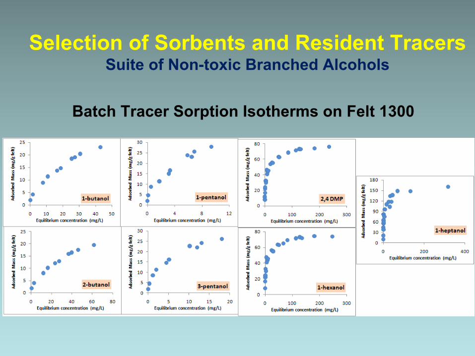
Selection of Sorbents and Resident Tracers Suite of Non-toxic Branched Alcohols
Batch Tracer Sorption Isotherms on Felt 1300

Resident Tracer Results●
Water Flux Measurements can be interpreted from resident tracer losses.
●
Tracer retardation factors and elution functions are sensitive to the nonlinear sorption isotherms.
●
Consistent use of tracers and sorbents is critical!

Laboratory Fracture Simulator
Fracture Dimensions:• Horizontal • Aperture = 500 μm• Width = 26 cm• Length = 53 cm• Conductivity ~0.7 cm/s
Borehole:• Diameter 10.16 cm
Flow Convergence:• Maximum = 1.76
FlowFront
Up Gradient
Left
Right
BackDown Gradient
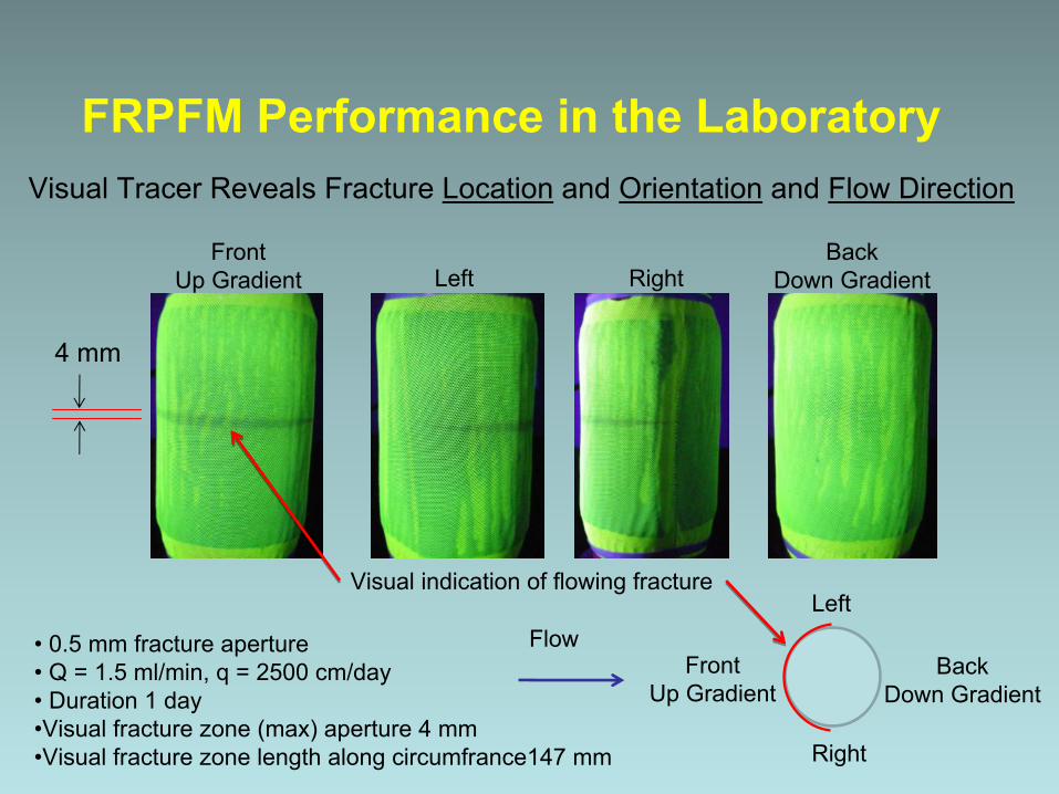
Visual Tracer Reveals Fracture Location
and Orientation
and Flow Direction
FrontUp Gradient
BackDown GradientLeft Right
• 0.5 mm fracture aperture• Q = 1.5 ml/min, q = 2500 cm/day• Duration 1 day•Visual fracture zone (max) aperture 4 mm •Visual fracture zone length along circumfrance147 mm
4 mm
Visual indication of flowing fracture
FRPFM Performance in the Laboratory
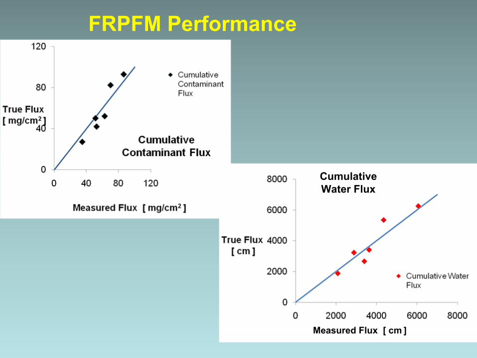
FRPFM Performance
Measured Flux [ cm
]
CumulativeWater Flux

Large Aquifer Box (High contrast flow zones)
Flow
Screened Wells (4-inch diameter PVC)
Alternating Sand and Gravel Layers
Box Dimensions(length x width x height)
2.0 x 0.5 x 1.3 m

Visual Indication of Flow

FRPFM Results in Aquifer Box

Guelph Tool Site, Ontario, Canada
Former Naval Air Warfare Center (NAWC),West Trenton, NJ
Two Field Sites

Site DescriptionGuelph Tool Site,Ontario, Canada
• Guelph Tool Inc. facility• Site is well characterized• Fractured Dolostone• High bulk conductivity• Medium to large apertures• TCE • Natural gradient conditions• Excellent infrastructure• Leverage the FRFRF

Test Design
Project will:
1.
Validate FRPFM performance in one or two fractured rock holes or sections of holes located in a chlorinated solvent plume
2.
Combine existing site data with new data generated from this study to explore potential cost-
savings derived from using the FRPFM in conjunction with other borehole technologies
Guelph Tool Site, Ontario, Canada
Zone Top Depth (mbTOC)
Bot Depth (mbTOC) T (m2/s)
Number of ATV
Fractures in Test Interval
ATV Fractures Equivilent 2b (μm)
1 40.5 43.04 1.59E-05 4 1852 39 40.5 1.78E-06 5 823 37.5 39 7.81E-06 4 1513 37.5 39 1.29E-06 4 794 36 37.5 4.47E-07 4 585 34.5 36 1.97E-06 5 896 33 34.5 1.58E-06 6 787 31.5 33 2.98E-06 5 1028 30 31.5 2.62E-06 1 1599 28.5 30 4.47E-05 4 258
MW 26 (first 12 meters)
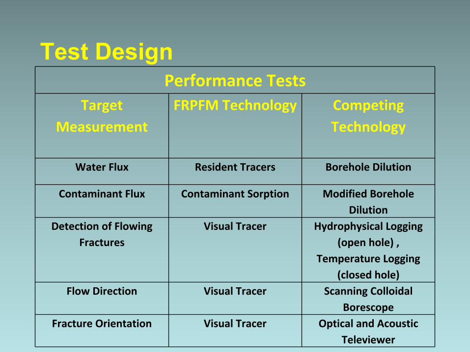
Test DesignPerformance Tests
Target Measurement
FRPFM Technology Competing Technology
Water Flux Resident Tracers Borehole Dilution
Contaminant Flux Contaminant Sorption Modified Borehole Dilution
Detection of Flowing Fractures
Visual Tracer Hydrophysical Logging (open hole) ,
Temperature Logging (closed hole)
Flow Direction Visual Tracer Scanning Colloidal Borescope
Fracture Orientation Visual Tracer Optical and Acoustic Televiewer

Field-Scale Prototype Test: Deployment
Well MW-26: Nominal 4-inch open borehole.

Selected zone for location of FRPFM based upon ATV, Tadpoles, HPL, HRTP, and Caliper data
MW-26Target Zone for Deployment
FRPFM Measured Water Fluxes:• 9.6 cm/d average specific discharge• 36-180 m/d fracture flow
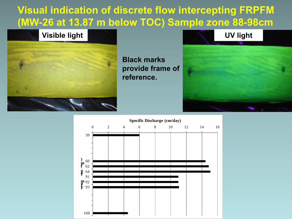
Visual indication of discrete flow intercepting FRPFM (MW-26 at 13.87 m below TOC) Sample zone 88-98cm
Visible light UV light
Black marks provide frame of reference.
0 2 4 6 8 10 12 14 16
39
606264919293
108
Specific Discharge (cm/day)
From top (cm)
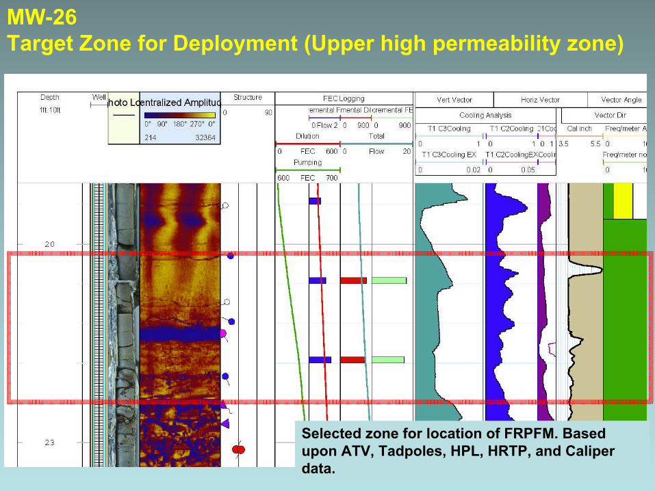
MW-26Target Zone for Deployment (Upper high permeability zone)
Selected zone for location of FRPFM. Based upon ATV, Tadpoles, HPL, HRTP, and Caliper data.
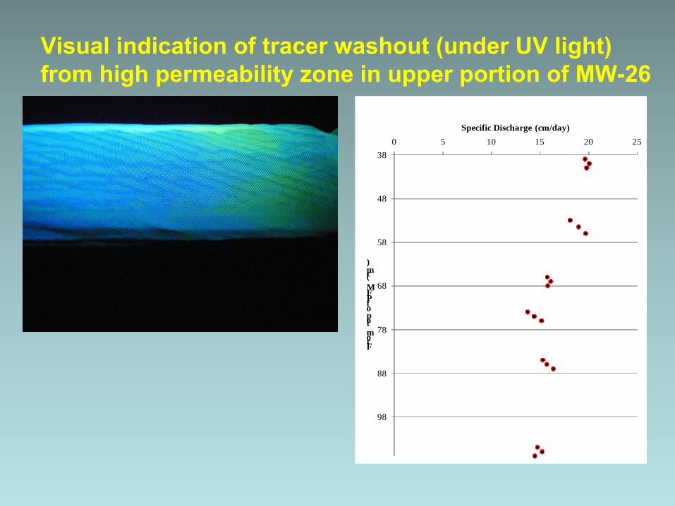
Visual indication of tracer washout (under UV light) from high permeability zone in upper portion of MW-26
38
48
58
68
78
88
98
0 5 10 15 20 25
From top of PFM (cm)
Specific Discharge (cm/day)

Visual indication of discrete flow intercepting FRPFM MW-25 at 26ft bgs (under UV light)

Physical Setup: Transect, Borehole(s), Traces,
Intersections
Problems:
(1)Estimate discharge Q
through traces in transect from measured fluxes qi
at borehole- trace intersections
(2)Quantify estimation uncertainty
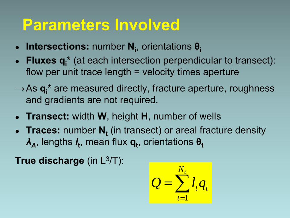
Parameters Involved●
Intersections:
number Ni
, orientations θi
●
Fluxes qi
* (at each intersection perpendicular to transect): flow per unit trace length = velocity times aperture
→As qi
*
are measured directly, fracture aperture, roughness and gradients are not required.
●
Transect:
width W, height H, number of wells●
Traces:
number Nt
(in transect) or areal fracture density λA
, lengths lt
, mean flux qt
, orientations θt
True discharge (in L3/T):
=
=tN
tttqlQ
1
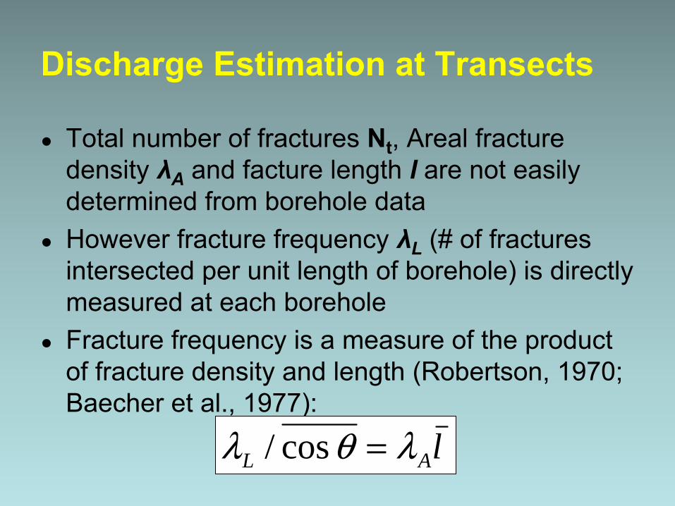
Discharge Estimation at Transects
●
Total number of fractures
Nt
, Areal fracture density λA
and facture length l
are not easily determined from borehole data
●
However fracture frequency
λL
(# of fractures intersected per unit length of borehole) is directly measured at each borehole
●
Fracture frequency is a measure of the product of fracture density and length (Robertson, 1970; Baecher
et al., 1977):
lAL λθλ =cos/
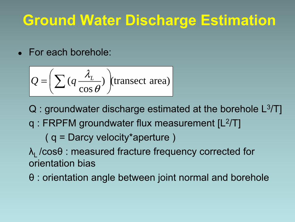
Ground Water Discharge Estimation
●
For each borehole:
Q : groundwater discharge estimated at the borehole L3/T]q : FRPFM groundwater flux measurement [L2/T]
( q = Darcy velocity*aperture )λL /cosθ
: measured fracture frequency corrected for orientation biasθ
: orientation angle between joint normal and borehole
area)(transect )cos
(
= θ
λLqQ

Contaminant Discharge Estimation
●
At each borehole:
MQ
: contaminant mass discharge estimated at the borehole [M/T]Jc
: FRPFM mass flux measurement [M/LT]( Jc
= contaminant mass flux*aperture )λL /cosθ
: measured fracture frequency corrected for orientation biasθ
: orientation angle between joint normal and borehole
area)(transect )cos
(
= θ
λLcQ JM
•
FRPFM was validated in the laboratory.
•
FRPFM is being demonstrated and validated in thefield.
•
Stochastic methods for estimating contaminant discharge look promising.
Project Status

Questions?