dell rapids custom trailers, inc. owners manual_0.pdf · 4 7.1. 6.4 tire pressure 52 7. inspection,...
TRANSCRIPT
1
Owner’s Manual
Dell Rapids Custom Trailers, Inc.
2
1. GENERAL SAFETY INFORMATION 6
1.1. SAFETY ALERT SYMBOLS AND SIGNAL WORDS 6 1.2. MAJOR HAZARDS 6 1.2.1. Improper Sizing of the Trailer to the Tow Vehicle 7 1.2.2. Driving Too Fast 7 1.2.3. Failure to Adjust Driving Behavior When Towing a Trailer 7 1.2.4. Trailer Not Properly Coupled to the Hitch 8 1.2.5. Proper Use of Safety Chains 8 1.2.6. Proper Connection of Breakaway Brake 8 1.2.7. Matching Trailer and Hitch 9 1.2.8. Worn Tires, Loose Wheels and Lug Nuts 9 1.2.9. Improper Loading 10 1.2.10. Unsafe Load Distribution 10 1.2.11. Shifting Cargo 11 1.2.12. Inappropriate Cargo 11 1.2.13. Inoperable Brakes, Lights or Mirrors 12 1.2.14. Hazards From Modifying Your Trailer 12 1.2.15. Hazards for Dump Trailers 12 1.2.16. Trailer Towing Guide 13 1.2.17. Reporting Safety Defects 13 1.2.18. Safe Trailer Towing Guidelines 14 1.3. SAFETY WARNING LABELS ON YOUR TRAILER 15
2. TIRE SAFETY INFORMATION 20
2.1. STEPS FOR DETERMINING CORRECT LOAD LIMIT – TRAILER 20 2.1.1. Trailers 10,000 Pounds GVWR or Less 20 2.1.2. Trailers Over 10,000 Pounds GVWR (**Note: These trailers are
not required to have a tire information placard on the vehicle**) 20
2.2. STEPS FOR DETERMINING CORRECT LOAD LIMIT – TOW VEHICLE 20 2.3. GLOSSARY OF TIRE TERMINOLOGY 21 2.4. TIRE SAFETY - EVERYTHING RIDES ON IT 23 2.4.1. Safety First–Basic Tire Maintenance 24 2.4.2. Finding Your Vehicle / TRAILERS Recommended Tire
Pressure and Load Limits 24 2.4.3. Understanding Tire Pressure and Load Limits 24 2.4.4. Checking Tire Pressure 24 2.4.5. Steps for Maintaining Proper Tire Pressure 25 2.4.6. Tire Size 25 2.4.7. Tire Tread 25 2.4.8. Tire Balance and Wheel Alignment 26 2.4.9. Tire Repair 26 2.4.10. Tire Fundamentals 26 2.4.10.1. Information on Passenger Vehicle Tires 26 2.4.10.2. UTQGS Information 27 2.4.10.3. Additional Information on Light Truck Tires 27 2.4.11. Tire Safety Tips 27
3. COUPLING TO THE TOW VEHICLE 28
3.1. USE AN ADEQUATE TOW VEHICLE AND HITCH 28
3
3.1.1. Trailer Information 28 3.2. COUPLING AND UNCOUPLING THE TRAILER 30 3.2.1. Various Coupler Designs 31 3.2.2. Trailer with Ball-Hitch Coupler 31 3.2.2.1. Before coupling the trailer to the tow vehicle 32 3.2.2.2. Prepare the coupler and hitch 32 3.2.2.3. Couple the trailer to the tow vehicle 33 3.2.2.4. Rig the safety chains 34 3.2.2.5. Connect the electrical cables 35 3.2.2.6. Uncoupling the Ball Hitch Trailer with Tongue Jack 36 3.2.3. Trailer with Gooseneck Coupler and Drop-leg Jack 36 3.2.3.1. Prepare the ball receiver and gooseneck ball 38 3.2.3.2. Couple the trailer to the tow vehicle 38 3.2.3.3. Rig the safety chains 39 3.2.3.4. Attach and test the breakaway brake system 39 3.2.3.5. Connect the electrical cables 40 3.2.3.6. Uncoupling the Gooseneck Trailer with Drop-leg Jack 41 3.2.4. Trailer with Fifth-wheel Coupler and Drop-leg Jack 42
4. LOADING THE TRAILER 43
4.1. TONGUE WEIGHT 43 4.2. CHECKING TONGUE WEIGHT 44 4.3. SECURING THE CARGO 45 4.3.1. Distributing THE CARGO (Open Trailer) 45 4.3.1.1. Preparing the Trailer for Loading 46 4.3.1.2. Loading a Rigid-deck Trailer 46 4.3.1.3. Loading a Pivoting-deck (Tilt-Bed) Trailer 46 4.4. LOADING THE DUMP TRAILER 47 4.4.1. Payload Capacity: 47 4.4.2. Loading Cargo: 47 4.4.3. Loading Flowable material: 48 4.4.4. Loading Fixed Loads (including equipment such as skid-steer loaders): 48 4.4.5. Securing the cargo: 48 4.4.6. Unloading Flowable Loads from the Dump Trailer: 48 4.4.7. Hydraulic Components: 49 4.4.8. Body Prop: 49 4.4.9. Unload Bulk Material Using The Spreader Gate 49
5. CHECKING THE TRAILER BEFORE AND DURING EACH TOW 51
5.1. PRE-TOW CHECKLIST 51 5.2. MAKE REGULAR STOPS 51
6. BREAKING-IN A NEW TRAILER 52
6.1. RETIGHTEN LUG NUTS AT FIRST 10, 25 & 50 MILES 52 6.2. ADJUST BRAKE SHOES AT FIRST 200 MILES 52 6.3. SYNCHRONIZING THE BRAKE SYSTEMS 52
4
6.4 TIRE PRESSURE 52
7. INSPECTION, SERVICE & MAINTENANCE 53
7.1. INSPECTION, SERVICE & MAINTENANCE SUMMARY CHARTS 53 Inspection and Service before Each Use 53 Inspection and Service each 3 Months or 3,000 Miles 54 Inspection and Service each 6 Months or 6,000 Miles 54 Inspection and Service Each Year or 12,000 Miles 54 7.2. INSPECTION AND SERVICE INSTRUCTIONS 55 7.2.1. Axle Bolts, Frame, Suspension, & Structure 55 7.2.2. Trailer Structure 55 7.2.2.1. Fasteners and Frame Members 55 7.2.2.2. Welds 56 7.2.3. Trailer Brakes 56 7.2.3.1. Brake Shoes and Drums 56 7.2.3.2. Manually Adjusting Brake Shoes 56 7.2.3.3. Brakes, Electric 57 7.2.3.3.A.(i) Breakaway Brake 57 7.2.3.3.A.(ii) Breakaway Battery 57 7.2.3.3.A.(iii) Breakaway Switch 57 7.2.3.3.B. Tow Vehicle Operated Electric Brakes 57 7.2.3.3.C. Magnets for all Electric Brakes 57 7.2.3.4. Brakes, Hydraulic (vacuum, air or electric operated) 57 7.2.3.4.A. Vacuum-operated hydraulic 58 7.2.3.4.B. Air Pressure-operated Hydraulic 58 7.2.3.4.C. Electrical-operated Hydraulic 58 7.2.4. Trailer Connection to Tow Vehicle 58 7.2.4.1. Coupler and Ball 58 7.2.4.2. Gooseneck 59 7.2.4.3. Fifth Wheel Kingpin 59 7.2.5. Landing Leg or Jack 59 7.2.6. Lights and Signals 59 7.2.7. Accessory Battery 59 7.2.8. Tires 60 7.2.9. Wheel Rims 61 7.2.10. Wheels, Bearings and Lug Nuts 61 7.2.10.1. Unsealed Bearings (Hubs) 61 7.2.10.2. Lug Nuts (Bolts) 62
8. WARRANTY INFORMATION 64
9. MAINTENANCE RECORDS: SERVICE & WARRANTY WORK 65
10. DIAGRAMS 67
11. LINKS 72
5
This User’s Manual contains safety information & instructions for your trailer. You must read this manual before loading or towing your trailer. Following all safety precautions and instructions will only insure your safety while your are traveling, along with all the lives you encounter on the road.
** All information in Issue No. 2 of the DCT Trailers Inc. User’s Manual is current at the time of print **
6
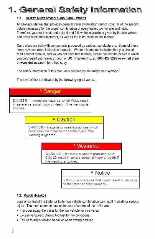
1.1. SAFETY ALERT SYMBOLS AND SIGNAL WORDS
An Owner’s Manual that provides general trailer information cannot cover all of the specific details necessary for the proper combination of every trailer, tow vehicle and hitch. Therefore, you must read, understand and follow the instructions given by the tow vehicle and trailer hitch manufacturers, as well as the instructions in this manual. Our trailers are built with components produced by various manufacturers. Some of these items have separate instruction manuals. Where this manual indicates that you should read another manual, and you do not have that manual, please contact the dealer in which you purchased your trailer through or DCT Trailers Inc. at (605) 428-3299 or e-mail them at www.dct-usa.com for a free copy. The safety information in this manual is denoted by the safety alert symbol: ^ The level of risk is indicated by the following signal words.
1.2. MAJOR HAZARDS
Loss of control of the trailer or trailer/tow vehicle combination can result in death or serious injury. The most common causes for loss of control of the trailer are:
Improper sizing the trailer for the tow vehicle, or vice versa.
Excessive Speed: Driving too fast for the conditions.
Failure to adjust driving behavior when towing a trailer.
7
Overloading and/or improper weight distribution.
Improper or mis-coupling of the trailer to the hitch.
Improper braking and steering under sway conditions.
Not maintaining proper tire pressure.
Not keeping lug nuts tight.
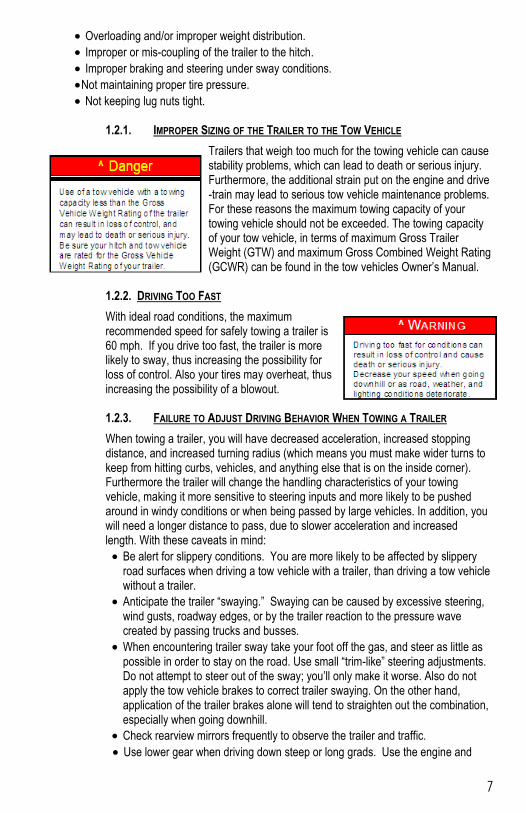
1.2.1. IMPROPER SIZING OF THE TRAILER TO THE TOW VEHICLE
Trailers that weigh too much for the towing vehicle can cause stability problems, which can lead to death or serious injury. Furthermore, the additional strain put on the engine and drive-train may lead to serious tow vehicle maintenance problems. For these reasons the maximum towing capacity of your towing vehicle should not be exceeded. The towing capacity of your tow vehicle, in terms of maximum Gross Trailer Weight (GTW) and maximum Gross Combined Weight Rating (GCWR) can be found in the tow vehicles Owner’s Manual.
1.2.2. DRIVING TOO FAST
With ideal road conditions, the maximum recommended speed for safely towing a trailer is 60 mph. If you drive too fast, the trailer is more likely to sway, thus increasing the possibility for loss of control. Also your tires may overheat, thus increasing the possibility of a blowout. 1.2.3. FAILURE TO ADJUST DRIVING BEHAVIOR WHEN TOWING A TRAILER
When towing a trailer, you will have decreased acceleration, increased stopping distance, and increased turning radius (which means you must make wider turns to keep from hitting curbs, vehicles, and anything else that is on the inside corner). Furthermore the trailer will change the handling characteristics of your towing vehicle, making it more sensitive to steering inputs and more likely to be pushed around in windy conditions or when being passed by large vehicles. In addition, you will need a longer distance to pass, due to slower acceleration and increased length. With these caveats in mind:
Be alert for slippery conditions. You are more likely to be affected by slippery road surfaces when driving a tow vehicle with a trailer, than driving a tow vehicle without a trailer.
Anticipate the trailer “swaying.” Swaying can be caused by excessive steering, wind gusts, roadway edges, or by the trailer reaction to the pressure wave created by passing trucks and busses.
When encountering trailer sway take your foot off the gas, and steer as little as possible in order to stay on the road. Use small “trim-like” steering adjustments. Do not attempt to steer out of the sway; you’ll only make it worse. Also do not apply the tow vehicle brakes to correct trailer swaying. On the other hand, application of the trailer brakes alone will tend to straighten out the combination, especially when going downhill.
Check rearview mirrors frequently to observe the trailer and traffic.
Use lower gear when driving down steep or long grads. Use the engine and
8
transmission as a brake. Do not ride the brakes, as they can overheat and become ineffective.
Be aware of your trailer and your cargo height, especially when approaching bridges, roofed areas and around trees.
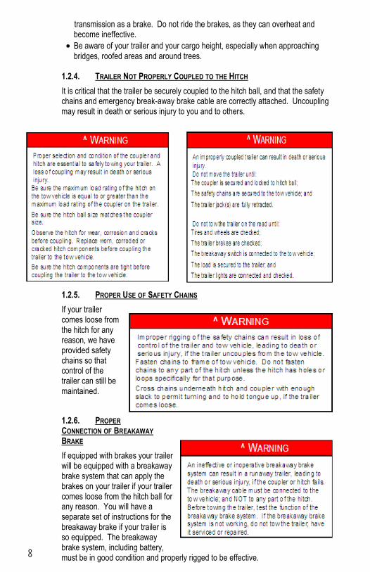
1.2.4. TRAILER NOT PROPERLY COUPLED TO THE HITCH
It is critical that the trailer be securely coupled to the hitch ball, and that the safety chains and emergency break-away brake cable are correctly attached. Uncoupling may result in death or serious injury to you and to others.
1.2.5. PROPER USE OF SAFETY CHAINS
If your trailer comes loose from the hitch for any reason, we have provided safety chains so that control of the trailer can still be maintained.
1.2.6. PROPER CONNECTION OF BREAKAWAY BRAKE
If equipped with brakes your trailer will be equipped with a breakaway brake system that can apply the brakes on your trailer if your trailer comes loose from the hitch ball for any reason. You will have a separate set of instructions for the breakaway brake if your trailer is so equipped. The breakaway brake system, including battery, must be in good condition and properly rigged to be effective.
9
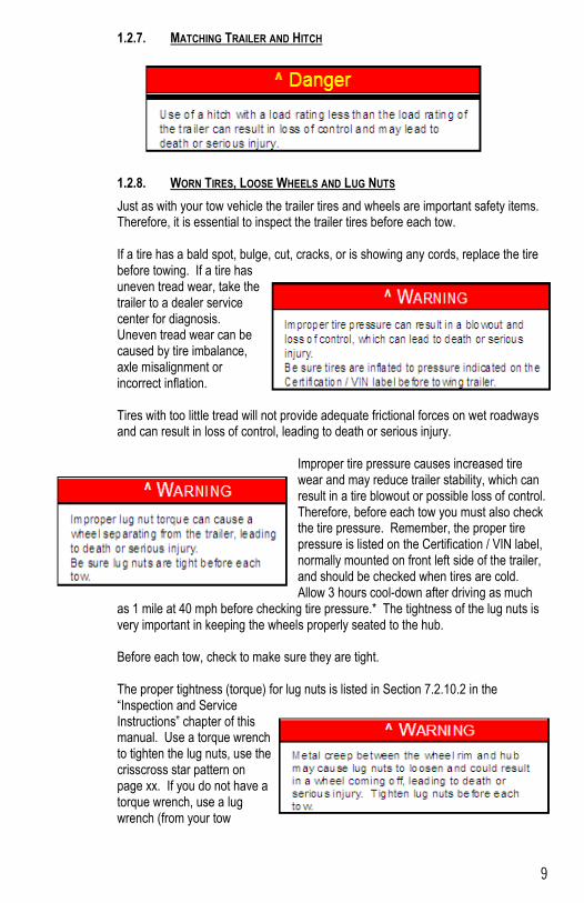
1.2.7. MATCHING TRAILER AND HITCH 1.2.8. WORN TIRES, LOOSE WHEELS AND LUG NUTS
Just as with your tow vehicle the trailer tires and wheels are important safety items. Therefore, it is essential to inspect the trailer tires before each tow. If a tire has a bald spot, bulge, cut, cracks, or is showing any cords, replace the tire before towing. If a tire has uneven tread wear, take the trailer to a dealer service center for diagnosis. Uneven tread wear can be caused by tire imbalance, axle misalignment or incorrect inflation. Tires with too little tread will not provide adequate frictional forces on wet roadways and can result in loss of control, leading to death or serious injury.
Improper tire pressure causes increased tire wear and may reduce trailer stability, which can result in a tire blowout or possible loss of control. Therefore, before each tow you must also check the tire pressure. Remember, the proper tire pressure is listed on the Certification / VIN label, normally mounted on front left side of the trailer, and should be checked when tires are cold. Allow 3 hours cool-down after driving as much
as 1 mile at 40 mph before checking tire pressure.* The tightness of the lug nuts is very important in keeping the wheels properly seated to the hub. Before each tow, check to make sure they are tight. The proper tightness (torque) for lug nuts is listed in Section 7.2.10.2 in the “Inspection and Service Instructions” chapter of this manual. Use a torque wrench to tighten the lug nuts, use the crisscross star pattern on page xx. If you do not have a torque wrench, use a lug wrench (from your tow
10
vehicle) and tighten the nuts as much as you can. At the first opportunity, have a service garage or trailer dealer tighten the lug nuts to the proper torque. Lug nuts are also prone to loosen after first being assembled. When driving a new trailer (or after wheels have been remounted), check to make sure they are tight after the first 10, 25
and 50 miles of driving and before each tow thereafter. Failure to perform this check can result in a wheel separating from the trailer and a crash, leading to death or serious injury. 1.2.9. IMPROPER LOADING
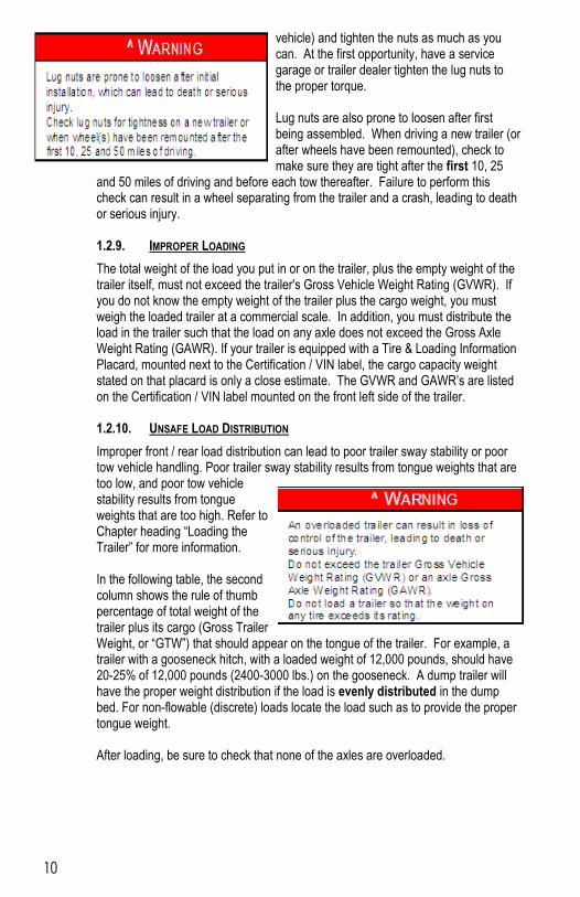
The total weight of the load you put in or on the trailer, plus the empty weight of the trailer itself, must not exceed the trailer's Gross Vehicle Weight Rating (GVWR). If you do not know the empty weight of the trailer plus the cargo weight, you must weigh the loaded trailer at a commercial scale. In addition, you must distribute the load in the trailer such that the load on any axle does not exceed the Gross Axle Weight Rating (GAWR). If your trailer is equipped with a Tire & Loading Information Placard, mounted next to the Certification / VIN label, the cargo capacity weight stated on that placard is only a close estimate. The GVWR and GAWR’s are listed on the Certification / VIN label mounted on the front left side of the trailer. 1.2.10. UNSAFE LOAD DISTRIBUTION
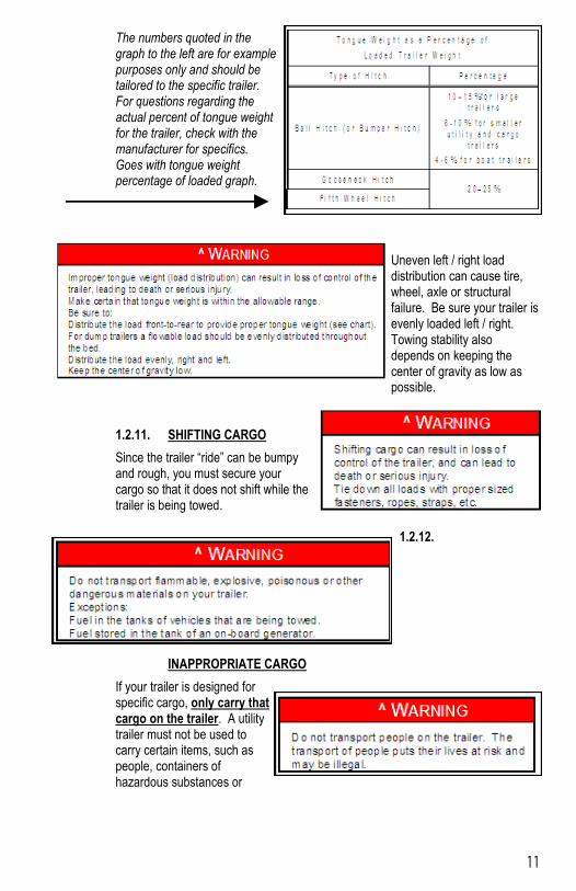
Improper front / rear load distribution can lead to poor trailer sway stability or poor tow vehicle handling. Poor trailer sway stability results from tongue weights that are too low, and poor tow vehicle stability results from tongue weights that are too high. Refer to Chapter heading “Loading the Trailer” for more information. In the following table, the second column shows the rule of thumb percentage of total weight of the trailer plus its cargo (Gross Trailer Weight, or “GTW”) that should appear on the tongue of the trailer. For example, a trailer with a gooseneck hitch, with a loaded weight of 12,000 pounds, should have 20-25% of 12,000 pounds (2400-3000 lbs.) on the gooseneck. A dump trailer will have the proper weight distribution if the load is evenly distributed in the dump bed. For non-flowable (discrete) loads locate the load such as to provide the proper tongue weight. After loading, be sure to check that none of the axles are overloaded.
11
The numbers quoted in the graph to the left are for example purposes only and should be tailored to the specific trailer. For questions regarding the actual percent of tongue weight for the trailer, check with the manufacturer for specifics. Goes with tongue weight percentage of loaded graph.
Uneven left / right load distribution can cause tire, wheel, axle or structural failure. Be sure your trailer is evenly loaded left / right. Towing stability also depends on keeping the center of gravity as low as possible.
1.2.11. SHIFTING CARGO
Since the trailer “ride” can be bumpy and rough, you must secure your cargo so that it does not shift while the trailer is being towed.
1.2.12.
INAPPROPRIATE CARGO
If your trailer is designed for specific cargo, only carry that cargo on the trailer. A utility trailer must not be used to carry certain items, such as people, containers of hazardous substances or
12
containers of flammable substances. If your trailer is designed for specific cargo, only carry that cargo on the trailer. A utility trailer must not be used to carry certain items, such as people, containers of hazardous substances or containers of flammable substances. 1.2.13. INOPERABLE BRAKES, LIGHTS OR MIRRORS
Be sure that the electric brakes and all of the lights on your trailer are functioning properly before towing your trailer. Electric brakes and lights on a trailer are controlled via a connection to the tow vehicle, generally a multi-pin electrical connector. Check the trailer tail lights by turning on your tow vehicle headlights. Check the trailer brake lights by having someone step on the tow vehicle brake pedal while you look at trailer lights. Do the same thing to check the turn signal lights. If your trailer has electric brakes, your tow vehicle will have an electric brake controller
that sends power to the trailer brakes. Before towing the trailer on the road, you must operate the brake controller while trying to pull the trailer in order to confirm that the electric brakes operate. While towing the trailer at less than 5 mph, manually operate the electric brake controller in the tow vehicle cab. You should feel the operation of the trailer brakes. If your trailer has hydraulic “surge” brakes, pull the emergency break-away brake lanyard to check the operation of the surge mechanism. Standard mirrors usually do not provide adequate visibility for viewing traffic to the sides and rear a towed trailer. You must provide mirrors that allow you to safely observe approaching traffic. 1.2.14. HAZARDS FROM MODIFYING YOUR TRAILER
Essential safety items can be damaged by altering your trailer. Prior making any alteration to your trailer, please contact the dealer in which you purchased your trailer through or DCT Trailers Inc. at (605) 428-3299 or e-mail them at [email protected] and describe the alteration you are contemplating. Alteration of the trailer structure or modification of mechanical or electrical along with other systems on your trailer must be performed only by qualified technicians who are familiar with the system as installed on your trailer. 1.2.15. HAZARDS FOR DUMP TRAILERS
Overloading.
Improper weight distribution; both side to side and front to back.
Getting under a raised dump bed.
Not using, or improperly using, the body prop.
Modifying or altering hydraulic components.

13
Modifying or altering dump controls.
Not dumping from a solid and level foundation.
Not fully opening rear doors when dumping.
Jerking the trailer, or hydraulics, to loosen the load. 1.2.16. TRAILER TOWING GUIDE
Driving a vehicle with a trailer in tow is vastly different from driving the same vehicle without a trailer in tow. Acceleration, maneuverability and braking are all diminished with a trailer in tow. It takes longer to get up to speed; you need more room to turn and pass, and more distance to stop when towing a trailer. You will need to spend time adjusting to the different feel and maneuverability of the tow vehicle with a loaded trailer. Because of the significant differences in all aspects of maneuverability when towing a trailer, the hazards and risks of injury are also much greater than when driving without a trailer. You are responsible for keeping your vehicle and trailer in control, and for all the damage that is caused if you lose control of your vehicle and trailer. As you did when learning to drive an automobile, find an open area with little or no traffic for your first practice trailering. Of course, before you start towing the trailer, you must follow all of the instructions for inspection, testing, loading and coupling. Also, before you start towing, adjust the mirrors so you can see the trailer as well as the area to the rear of it. Drive slowly at first, 5 mph or so, and turn the wheel to get the feel of how the tow vehicle and trailer combination responds. Next, make some right and left hand turns. Watch in your side mirrors to see how the trailer follows the tow vehicle. Turning with a trailer attached requires more room. Stop the rig a few times from speeds no greater than 10 mph. If your trailer is equipped with brakes, try using different combinations of trailer/electric brake and tow vehicle brake. Note the effect that the trailer brakes have when they are the only brakes used. When properly adjusted, the trailer brakes will come on just before the tow vehicle brakes. It will take practice to learn how to back up a tow vehicle with a trailer attached. Take it slow. Before backing up, get out of the tow vehicle and look behind the trailer to make sure that there are no obstacles. Some drivers place their hands at the bottom of the steering wheel, and while the tow vehicle is in reverse, “think” of the hands as being on the top of the wheel. When the hands move to the right (counter-clockwise, as you would do to turn the tow vehicle to the left when moving forward), the rear of the trailer moves to the right. Conversely, rotating the steering wheel clockwise with your hands at the bottom of the wheel will move the rear of the trailer to the left, while backing up. If you are towing a bumper hitch rig, be careful not to allow the trailer to turn too much, because it will hit the rear of the tow vehicle. To straighten the rig, either pull forward, or turn the steering wheel in the opposite direction. 1.2.17. REPORTING SAFETY DEFECTS
If you believe that your vehicle has a defect that could cause a crash or could cause injury or death, you should immediately inform the National Highway Traffic Safety Administration (NHTSA) in addition to notifying please your dealer in which you
14
purchased your trailer through or DCT Trailers Inc. at (605) 428-3299or e-mail them at [email protected]. If NHTSA receives similar complaints, it may open an investigation, and if it finds that a safety defect exists in a group of vehicles, it may order a recall and remedy campaign. However, NHTSA cannot become involved in individual problems between you, your dealer, or DCT Trailers Inc. To contact NHTSA, you may either call the Vehicle Safety Hotline toll-free at 1-888-327-4236 (TTY: 1-800-424-9153), go to http://www.safecar.gov; or write to: Administrator, NHTSA, 1200 New Jersey Avenue SE, Washington, DC 20590. You can also obtain other information about motor vehicle safety from www.safecar.gov. (Rev. 05/ 27/ 09) Please contact the dealer in which you purchased your trailer through or DCT Trailers Inc. at (605) 428-3299 or e-mail them at [email protected] if you plan on making any changes to you trailer. 1.2.18. SAFE TRAILER TOWING GUIDELINES
Recheck the load tie downs to make sure the load will not shift during towing.
Before towing, check coupling, safety chain, safety brake, tires, wheels and lights.
Check the lug nuts or bolts for tightness.
Check coupler tightness after towing 50 miles.
Adjust the brake controller to engage the trailer brakes before the tow vehicle brakes. Follow the instructions given with the brake controller manufacturer’s literature.
Use your mirrors to verify that you have room to change lanes or pull into traffic.
Use your turn signals well in advance.
Allow plenty of stopping space for your trailer and tow vehicle.
Do not drive so fast that the trailer begins to sway due to speed. Generally never drive faster than 60 m.p.h.
Allow plenty of room for passing. A rule of thumb is that the passing distance with a trailer is 4 times the passing distance without a trailer.
Shift your automatic transmission into a lower gear for city driving.
Use lower gears for climbing and descending grades.
Do not ride the brakes while descending grades; they may get so hot that they stop working. Then you will potentially have a runaway tow vehicle and trailer.
To conserve fuel, don't use full throttle to climb a hill. Instead, build speed on the approach.
Slow down for bumps in the road. Take your foot off the brake when crossing the bump.
Do not brake while in a curve unless absolutely necessary. Instead, slow down before you enter the curve.
Do not apply the tow vehicle brakes to correct extreme trailer swaying. Instead, lightly apply the trailer brakes with the hand controller.
Make regular stops, about once each hour. Confirm that 1. The coupler is secure to the hitch and is locked,
15
2. Electrical connectors are made, 3. There is appropriate slack in the safety chains, 4. There is appropriate slack in the breakaway switch pullpin cable, 5. The tires are not visibly low on pressure, and
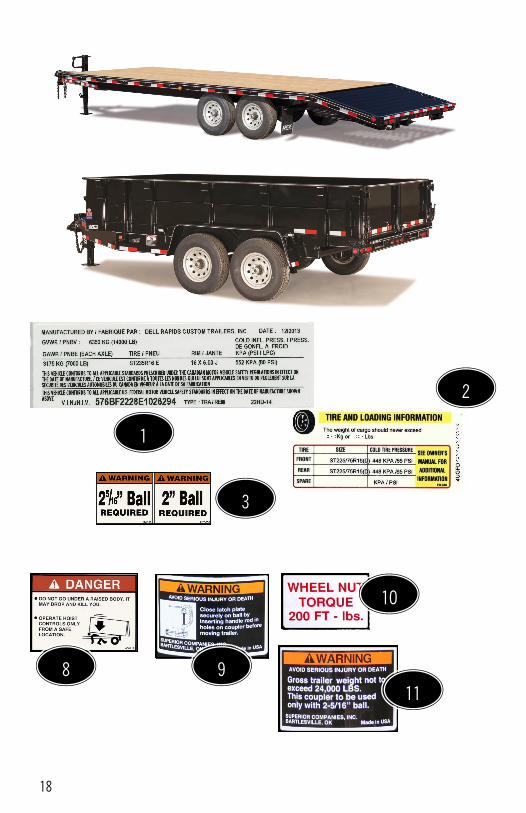
6. The cargo is secure and in good condition. 1.3. SAFETY WARNING LABELS ON YOUR TRAILER
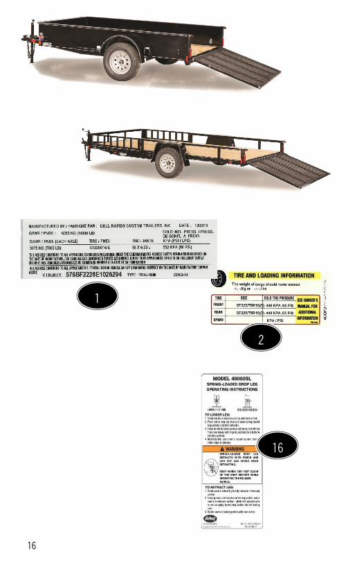
On the following pages you will find pictures of each type of trailer along with each label that we affix to each trailer / trailer type.
The following labels are for the trailers shown on pages 16 & 17 of this DCT Trailers Inc. Users Manual:
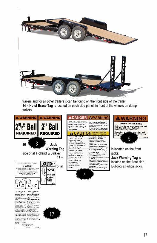
1 = VIN Tag is located on the inside of the hitch, passenger side AND MUST be visible from the drivers side. 2 = Tire & Loading Information Tag is located on the inside of the hitch, passenger side AND MUST be visible from the drivers side. This applies for all trailers that are rated 10,000 Lbs. GVW and under. 3 = Ball Coupler size requirements Tag is located on or near the coupler of your trailer. 4 = Danger, Warning, Caution Tag is located on the backside of the fenders of single axle utility trailers and for all other trailers it can be found on the front side of the trailer. 5 = Check Wheel Lugs Tag is located on the back side of the fenders of the single axle utility trailers, on the each fender above the wheels and on the rub rails above the wheels on all trailers that do not have fenders. 16 = Jack Warning Tag is located on the front side of all Holland & Binkley jacks. 17 = Jack Warning / Pinch Point Tag(s) is located on the front side of all Bulldog & Fulton jacks.
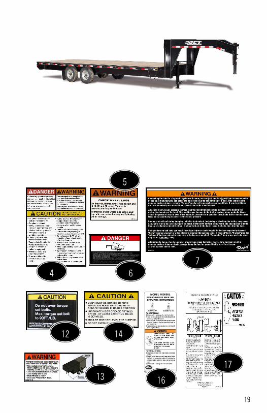
The following labels are for the trailers shown on pages 18 & 19 of this DCT Trailers Inc. Users Manual:
1 = VIN Tag is located on the inside of the hitch, passenger side AND MUST be visible from the drivers side. 2 = Tire & Loading Information Tag is located on the inside of the hitch, passenger side AND MUST be visible from the drivers side. This applies for all trailers that are rated 10,000 Lbs. GVW and under. 3 = Ball Coupler size requirements Tag is located on or near the coupler of your trailer. 4 = Danger, Warning, Caution Tag is located on the backside of the fenders of single axle utility trailers and for all other trailers it can be found on the front side of the trailer. 5 = Check Wheel Lugs Tag is located on the back side of the fenders of the single axle utility trailers, on the each fender above the wheels and on the rub rails above the wheels on all trailers that do not have fenders. 6 = Hoist Danger Tag is located on each side panel, in front of the wheels on dump trailers. 7 = Hoist Operation Danger Tag is located on the front side above the hitch &/or toolbox of a dump trailer. 8 = Hoist Operation Danger Tag is located on the front side above the hitch &/or toolbox of a dump trailer. 9 = Gooseneck Latch Plate Tag is located on the lower front side of all gooseneck couplers. 10 = Wheel Nut Torque Tag is located on the rim & rub rail of all dually tires. 11 = GVW Tag is located on the lower front side of all gooseneck couplers. 12 = Set Bolts Tag is located on the middle front side of all gooseneck couplers. 13 = Improper Loading Tag is located on the backside of the fenders of single axle utility
16
16
1
2
17
trailers and for all other trailers it can be found on the front side of the trailer. 14 = Hoist Brace Tag is located on each side panel, in front of the wheels on dump trailers.
16 = Jack Warning Tag is located on the front
side of all Holland & Binkley jacks. 17 = Jack Warning Tag is
located on the front side of all Bulldog & Fulton jacks.
4
3 5
17
18
2
3
11
10
9 8
1
19
4
5
6
7
17
16
14
13
12
20
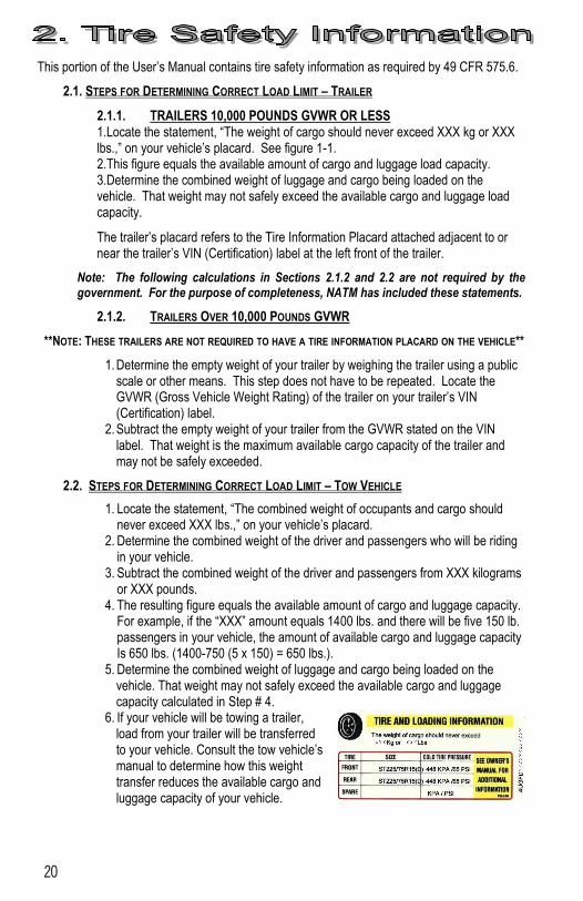
This portion of the User’s Manual contains tire safety information as required by 49 CFR 575.6.
2.1. STEPS FOR DETERMINING CORRECT LOAD LIMIT – TRAILER
2.1.1. TRAILERS 10,000 POUNDS GVWR OR LESS 1.Locate the statement, “The weight of cargo should never exceed XXX kg or XXX lbs.,” on your vehicle’s placard. See figure 1-1. 2.This figure equals the available amount of cargo and luggage load capacity. 3.Determine the combined weight of luggage and cargo being loaded on the vehicle. That weight may not safely exceed the available cargo and luggage load capacity.
The trailer’s placard refers to the Tire Information Placard attached adjacent to or near the trailer’s VIN (Certification) label at the left front of the trailer.
Note: The following calculations in Sections 2.1.2 and 2.2 are not required by the government. For the purpose of completeness, NATM has included these statements.
2.1.2. TRAILERS OVER 10,000 POUNDS GVWR
**NOTE: THESE TRAILERS ARE NOT REQUIRED TO HAVE A TIRE INFORMATION PLACARD ON THE VEHICLE**
1. Determine the empty weight of your trailer by weighing the trailer using a public scale or other means. This step does not have to be repeated. Locate the GVWR (Gross Vehicle Weight Rating) of the trailer on your trailer’s VIN (Certification) label.
2. Subtract the empty weight of your trailer from the GVWR stated on the VIN label. That weight is the maximum available cargo capacity of the trailer and may not be safely exceeded.
2.2. STEPS FOR DETERMINING CORRECT LOAD LIMIT – TOW VEHICLE
1. Locate the statement, “The combined weight of occupants and cargo should never exceed XXX lbs.,” on your vehicle’s placard.
2. Determine the combined weight of the driver and passengers who will be riding in your vehicle.
3. Subtract the combined weight of the driver and passengers from XXX kilograms or XXX pounds.
4. The resulting figure equals the available amount of cargo and luggage capacity. For example, if the “XXX” amount equals 1400 lbs. and there will be five 150 lb. passengers in your vehicle, the amount of available cargo and luggage capacity Is 650 lbs. (1400-750 (5 x 150) = 650 lbs.).
5. Determine the combined weight of luggage and cargo being loaded on the vehicle. That weight may not safely exceed the available cargo and luggage capacity calculated in Step # 4.
6. If your vehicle will be towing a trailer, load from your trailer will be transferred to your vehicle. Consult the tow vehicle’s manual to determine how this weight transfer reduces the available cargo and luggage capacity of your vehicle.
21
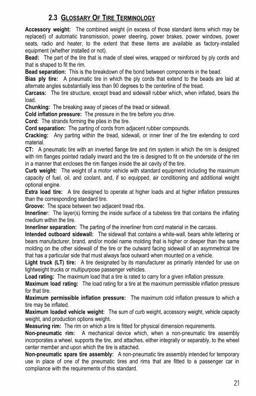
2.3 GLOSSARY OF TIRE TERMINOLOGY
Accessory weight: The combined weight (in excess of those standard items which may be replaced) of automatic transmission, power steering, power brakes, power windows, power seats, radio and heater, to the extent that these items are available as factory-installed equipment (whether installed or not). Bead: The part of the tire that is made of steel wires, wrapped or reinforced by ply cords and that is shaped to fit the rim. Bead separation: This is the breakdown of the bond between components in the bead. Bias ply tire: A pneumatic tire in which the ply cords that extend to the beads are laid at alternate angles substantially less than 90 degrees to the centerline of the tread. Carcass: The tire structure, except tread and sidewall rubber which, when inflated, bears the load. Chunking: The breaking away of pieces of the tread or sidewall. Cold inflation pressure: The pressure in the tire before you drive. Cord: The strands forming the plies in the tire. Cord separation: The parting of cords from adjacent rubber compounds. Cracking: Any parting within the tread, sidewall, or inner liner of the tire extending to cord material. CT: A pneumatic tire with an inverted flange tire and rim system in which the rim is designed with rim flanges pointed radially inward and the tire is designed to fit on the underside of the rim in a manner that encloses the rim flanges inside the air cavity of the tire. Curb weight: The weight of a motor vehicle with standard equipment including the maximum capacity of fuel, oil, and coolant, and, if so equipped, air conditioning and additional weight optional engine. Extra load tire: A tire designed to operate at higher loads and at higher inflation pressures than the corresponding standard tire. Groove: The space between two adjacent tread ribs. Innerliner: The layer(s) forming the inside surface of a tubeless tire that contains the inflating medium within the tire. Innerliner separation: The parting of the innerliner from cord material in the carcass. Intended outboard sidewall: The sidewall that contains a white-wall, bears white lettering or bears manufacturer, brand, and/or model name molding that is higher or deeper than the same molding on the other sidewall of the tire or the outward facing sidewall of an asymmetrical tire that has a particular side that must always face outward when mounted on a vehicle. Light truck (LT) tire: A tire designated by its manufacturer as primarily intended for use on lightweight trucks or multipurpose passenger vehicles. Load rating: The maximum load that a tire is rated to carry for a given inflation pressure. Maximum load rating: The load rating for a tire at the maximum permissible inflation pressure for that tire. Maximum permissible inflation pressure: The maximum cold inflation pressure to which a tire may be inflated. Maximum loaded vehicle weight: The sum of curb weight, accessory weight, vehicle capacity weight, and production options weight. Measuring rim: The rim on which a tire is fitted for physical dimension requirements. Non-pneumatic rim: A mechanical device which, when a non-pneumatic tire assembly incorporates a wheel, supports the tire, and attaches, either integrally or separably, to the wheel center member and upon which the tire is attached. Non-pneumatic spare tire assembly: A non-pneumatic tire assembly intended for temporary use in place of one of the pneumatic tires and rims that are fitted to a passenger car in compliance with the requirements of this standard.
22
Non-pneumatic tire: A mechanical device which transmits, both directly or through a wheel or wheel center member, the vertical load and tractive forces from the roadway to the vehicle, generates the tractive forces that provide the directional control of the vehicle and does not rely on the containment of any gas or fluid for providing those functions. Non-pneumatic tire assembly: A non-pneumatic tire, alone or in combination with a wheel or wheel center member, which can be mounted on a vehicle. Normal occupant weight: This means 68 kilograms (150 lbs.) times the number of occupants specified in the second column of Table I of 49 CFR 571.110. Occupant distribution: The distribution of occupants in a vehicle as specified in the third column of Table I of 49 CFR 571.110. Open splice: Any parting at any junction of tread, sidewall, or innerliner that extends to cord material. Outer diameter: The overall diameter of an inflated new tire. Overall width: The linear distance between the exteriors of the sidewalls of an inflated tire, including elevations due to labeling, decorations, or protective bands or ribs. Ply: A layer of rubber-coated parallel cords. Ply separation: A parting of rubber compound between adjacent plies. Pneumatic tire: A mechanical device made of rubber, chemicals, fabric and steel or other materials, that, when mounted on an automotive wheel, provides the traction and contains the gas or fluid that sustains the load. Production options weight: The combined weight of those installed regular production options weighing over 2.3 kilograms (5 lbs.) in excess of those standard items which they replace, not previously considered in curb weight or accessory weight, including heavy duty brakes, ride levelers, roof rack, heavy duty battery, and special trim. Radial ply tire: A pneumatic tire in which the ply cords that extend to the beads are laid at substantially 90 degrees to the centerline of the tread. Recommended inflation pressure: This is the inflation pressure provided by the vehicle manufacturer on the Tire Information label and on the Certification / VIN tag. Reinforced tire: A tire designed to operate at higher loads and at higher inflation pressures than the corresponding standard tire. Rim: A metal support for a tire or a tire and tube assembly upon which the tire beads are seated. Rim diameter: This means the nominal diameter of the bead seat. Rim size designation: This means the rim diameter and width. Rim type designation: This means the industry of manufacturer’s designation for a rim by style or code. Rim width: This means the nominal distance between rim flanges. Section width: The linear distance between the exteriors of the sidewalls of an inflated tire, excluding elevations due to labeling, decoration, or protective bands. Sidewall: That portion of a tire between the tread and bead. Sidewall separation: The parting of the rubber compound from the cord material in the sidewall. Special Trailer (ST) tire: The "ST" is an indication the tire is for trailer use only. Test rim: The rim on which a tire is fitted for testing, and may be any rim listed as appropriate for use with that tire. Tread: That portion of a tire that comes into contact with the road. Tread rib: A tread section running circumferentially around a tire. Tread separation: Pulling away of the tread from the tire carcass. Treadwear indicators (TWI): The projections within the principal grooves designed to give a visual indication of the degrees of wear of the tread.
23
Vehicle capacity weight: The rated cargo and luggage load plus 68 kilograms (150 lbs.) times the vehicle’s designated seating capacity. Vehicle maximum load on the tire: The load on an individual tire that is determined by distributing to each axle its share of the maximum loaded vehicle weight and dividing by two. Vehicle normal load on the tire: The load on an individual tire that is determined by distributing to each axle its share of the curb weight, accessory weight, and normal occupant weight (distributed in accordance with Table I of CRF 49 571.110) and dividing by 2. Weather side: The surface area of the rim not covered by the inflated tire. Wheel center member: In the case of a non-pneumatic tire assembly incorporating a wheel, a mechanical device which attaches, either integrally or separably, to the non-pneumatic rim and provides the connection between the non-pneumatic rim and the vehicle; or, in the case of a non-pneumatic tire assembly not incorporating a wheel, a mechanical device which attaches, either integrally or separably, to the non-pneumatic tire and provides the connection between tire and the vehicle. Wheel-holding fixture: The fixture used to hold the wheel and tire assembly securely during testing.
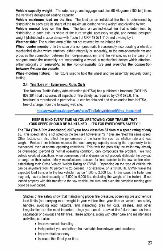
2.4. TIRE SAFETY - EVERYTHING RIDES ON IT
The National Traffic Safety Administration (NHTSA) has published a brochure (DOT HS 809 361) that discusses all aspects of Tire Safety, as required by CFR 575.6. This brochure is reproduced in part below. It can be obtained and downloaded from NHTSA, free of charge, from the following web site:
http://www.nhtsa.dot.gov/cars/rules/TireSafety/ridesonit/tires_index.html
KEEP IN MIND EVERY TIME AS YOU ARE TOWING YOUR TRAILER THAT YOUR SPEED SHOULD BE MAINTAINED … IT’S FOR EVERYONE’S SAFETY!!!
The TRA (Tire & Rim Association) 2007-year book classifies ST tires at a speed rating of only 65. This speed rating is not noted on the tire itself however all “ST” tires are rated this same speed. Other factors can also affect the performance of the trailer tire such as inflation rate and load weight. Reduced tire inflation reduces the load carrying capacity causing the opportunity to be overloaded, even at normal operating conditions. This, with the possibility the trailer may already be overloaded (beyond its normal operating condition), only compounds the problem. We fund vehicle overload conditions when consumers and end-users do not properly distribute the payload or cargo on their trailer. Many manufacturers account for load transfer to the tow vehicle when establishing their Gross Vehicle Weight Rating or GVWR. Depending on the type of vehicle this can be anywhere from 10 percent to 25 percent. For example, on a 10,000 lb. GVWR trailer the expected load transfer to the tow vehicle may be 1,000 to 2,500 lbs. In this case, the trailer tires may only have a load capacity of 7,500 to 9,000 lbs. (including the weight of the trailer). If not loaded properly with this transfer to the tow vehicle, the tires and even the complete running gear could be overloaded.
Studies of tire safety show that maintaining proper tire pressure, observing tire and vehicle load limits (not carrying more weight in your vehicle than your tires or vehicle can safely handle), avoiding road hazards, and inspecting tires for cuts, slashes, and other irregularities are the most important things you can do to avoid tire failure, such as tread separation or blowout and flat tires. These actions, along with other care and maintenance activities, can also:
Improve vehicle handling
Help protect you and others fro avoidable breakdowns and accidents
Improve fuel economy
Increase the life of your tires.
24
This booklet presents a comprehensive overview of tire safety, including information on the following topics:
Basic tire maintenance
Uniform Tire Quality Grading System
Fundamental characteristics of tires
Tire safety tips.
Use this information to make tire safety a regular part of your vehicle maintenance routine. Recognize that the time you spend is minimal compared with the inconvenience and safety consequences of a flat tire or other tire failure.
2.4.1. SAFETY FIRST–BASIC TIRE MAINTENANCE
Properly maintained tires improve the steering, stopping, traction, and load-carrying capability of your vehicle. Under inflated tires and overloaded vehicles are major causes of tire failure. Therefore, as mentioned above, to avoid flat tires and other types of tire failure, you should maintain proper tire pressure, observe tire and vehicle load limits, avoid road hazards, and regularly inspect your tires.
2.4.2. FINDING YOUR VEHICLE / TRAILER’S RECOMMENDED TIRE PRESSURE AND LOAD LIMITS
Tire information placards and vehicle certification labels contain information on tires and load limits. These labels indicate the vehicle manufacturer's information including:
Recommended tire size
Recommended tire inflation pressure
Vehicle capacity weight (VCW–the maximum occupant and cargo weight a vehicle is designed to carry)
Front and rear gross axle weight ratings (GAWR– the maximum weight the axle systems are designed to carry). Both placards and certification labels are permanently attached to the trailer near the left front.
2.4.3. UNDERSTANDING TIRE PRESSURE AND LOAD LIMITS
Tire inflation pressure is the level of air in the tire that provides it with load-carrying capacity and affects the overall performance of the vehicle. The tire inflation pressure is a number that indicates the amount of air pressure– measured in pounds per square inch (psi)–a tire requires to be properly inflated. (You will also find this number on the vehicle information placard expressed in kilopascals (kPa), which is the metric measure used internationally.) Manufacturers of passenger vehicles and light trucks determine this number based on the vehicle's design load limit, that is, the greatest amount of weight a vehicle can safely carry and the vehicle's tire size. The proper tire pressure for your vehicle is referred to as the "recommended cold inflation pressure." (As you will read below, it is difficult to obtain the recommended tire pressure if your tires are not cold.)
Because tires are designed to be used on more than one type of vehicle, tire manufacturers list the "maximum permissible inflation pressure" on the tire sidewall. This number is the greatest amount of air pressure that should ever be put in the tire under normal driving conditions.
2.4.4. CHECKING TIRE PRESSURE
It is important to check your vehicle's tire pressure at least once a month for the
25
following reasons:
Most tires may naturally lose air over time.
Tires can lose air suddenly if you drive over a pothole or other object or if you strike the curb when parking.
With radial tires, it is usually not possible to determine under inflation by visual inspection.
For convenience, purchase a tire pressure gauge to keep in your vehicle. Gauges can be purchased at tire dealerships, auto supply stores, and other retail outlets. The recommended tire inflation pressure that vehicle manufacturers provide reflects the proper psi when a tire is cold. The term cold does not relate to the outside temperature. Rather, a cold tire is one that has not been driven on for at least three hours. When you drive, your tires get warmer, causing the air pressure within them to increase. Therefore, to get an accurate tire pressure reading, you must measure tire pressure when the tires are cold or compensate for the extra pressure in warm tires.
2.4.5. STEPS FOR MAINTAINING PROPER TIRE PRESSURE
Step 1: Locate the recommended tire pressure on the vehicle's tire information placard, certification label, or in the owner's manual.
Step 2: Record the tire pressure of all tires.
Step 3: If the tire pressure is too high in any of the tires, slowly release air by gently pressing on the tire valve stem with the edge of your tire gauge until you get to the correct pressure.
Step 4: If the tire pressure is too low, note the difference between the measured tire pressure and the correct tire pressure. These "missing" pounds of pressure are what you will need to add.
Step 5: At a service station, add the missing pounds of air pressure to each tire that is underinflated.
Step 6: Check all the tires to make sure they have the same air pressure (except in cases in which the front and rear tires are supposed to have different amounts of pressure).
If you have been driving your vehicle and think that a tire is under inflated, fill it to the recommended cold inflation pressure indicated on your vehicle's tire information placard or certification label. While your tire may still be slightly under inflated due to the extra pounds of pressure in the warm tire, it is safer to drive with air pressure that is slightly lower than the vehicle manufacturer's recommended cold inflation pressure than to drive with a significantly under inflated tire. Since this is a temporary fix, don't forget to recheck and adjust the tire's pressure when you can obtain a cold reading.
2.4.6. TIRE SIZE
To maintain tire safety, purchase new tires that are the same size as the vehicle's original tires or another size recommended by the manufacturer. Look at the tire information placard, the owner's manual, or the sidewall of the tire you are replacing to find this information. If you have any doubt about the correct size to choose, consult with the tire dealer.
2.4.7. TIRE TREAD
The tire tread provides the gripping action and traction that prevent your vehicle from slipping or sliding, especially when the road is wet or icy. In general, tires are
26
not safe and should be replaced when the tread is worn down to 1/16 of an inch. Tires have built-in tread wear indicators that let you know when it is time to replace your tires. These indicators are raised sections spaced intermittently in the bottom of the tread grooves. When they appear "even" with the outside of the tread, it is time to replace your tires. Another method for checking tread depth is to place a penny in the tread with Lincoln's head upside down and facing you. If you can see the top of Lincoln's head, you are ready for new tires.
2.4.8. TIRE BALANCE AND WHEEL ALIGNMENT
To avoid vibration or shaking of the vehicle when a tire rotates, the tire must be properly balanced. This balance is achieved by positioning weights on the wheel to counterbalance heavy spots on the wheel-and-tire assembly. A wheel alignment adjusts the angles of the wheels so that they are positioned correctly relative to the vehicle's frame. This adjustment maximizes the life of your tires. These adjustments require special equipment and should be performed by a qualified technician.
2.4.9. TIRE REPAIR
The proper repair of a punctured tire requires a plug for the hole and a patch for the area inside the tire that surrounds the puncture hole. Punctures through the tread can be repaired if they are not too large, but punctures to the sidewall should not be repaired. Tires must be removed from the rim to be properly inspected before being plugged and patched.
2.4.10. TIRE FUNDAMENTALS
Federal law requires tire manufacturers to place standardized information on the sidewall of all tires. This information identifies and describes the fundamental characteristics of the tire and also provides a tire identification number for safety standard certification and in case of a recall.
2.4.10.1. INFORMATION ON PASSENGER VEHICLE TIRES
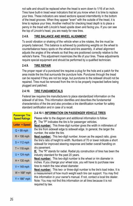
Please refer to the diagram and additional information to follow: P: The "P" indicates the tire is for passenger vehicles. Next number: This three-digit number gives the width in millimeters of the tire from sidewall edge to sidewall edge. In general, the larger the number, the wider the tire. Next number: This two-digit number, known as the aspect ratio, gives the tire's ratio of height to width. Numbers of 70 or lower indicate a short sidewall for improved steering response and better overall handling on dry pavement. R: The "R" stands for radial. Radial ply construction of tires has been the industry standard for the past 20 years. Next number: This two-digit number is the wheel or rim diameter in inches. If you change your wheel size, you will have to purchase new tires to match the new wheel diameter. Next number: This two- or three-digit number is the tire's load index. It is a measurement of how much weight each tire can support. You may find this information in your owner's manual. If not, contact a local tire dealer. Note: You may not find this information on all tires because it is not required by law.
Passenger Tire Speed Ratings
Letter = Speed
Q = 99 mph
R = 106 mph
S = 112 mph
T = 118 mph
U = 124 mph
H = 130 mph
V = 149 mph
W = 168* mph
Y = 186* mph
27
2.4.10.2. UTQGS Information
Treadwear Number: This number indicates the tire's wear rate. The higher the treadwear number is, the longer it should take for the tread to wear down. For example, a tire graded 400 should last twice as long as a tire graded 200. Traction Letter: This letter indicates a tire's ability to stop on wet pavement. A higher graded tire should allow you to stop your car on wet roads in a shorter distance than a tire with a lower grade. Traction is graded from highest to lowest as "AA","A", "B", and "C". Temperature Letter: This letter indicates a tire's resistance to heat. The temperature grade is for a tire that is inflated properly and not overloaded. Excessive speed, under inflation or excessive loading, either separately or in combination, can cause heat build-up and possible tire failure. From highest to lowest, a tire's resistance to heat is graded as "A", "B", or "C".
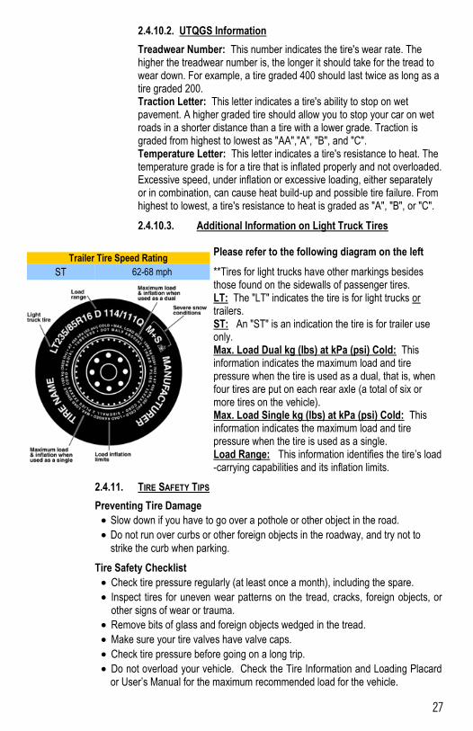
2.4.10.3. Additional Information on Light Truck Tires
Please refer to the following diagram on the left
**Tires for light trucks have other markings besides those found on the sidewalls of passenger tires. LT: The "LT" indicates the tire is for light trucks or trailers. ST: An "ST" is an indication the tire is for trailer use only. Max. Load Dual kg (lbs) at kPa (psi) Cold: This information indicates the maximum load and tire pressure when the tire is used as a dual, that is, when four tires are put on each rear axle (a total of six or more tires on the vehicle). Max. Load Single kg (lbs) at kPa (psi) Cold: This information indicates the maximum load and tire pressure when the tire is used as a single. Load Range: This information identifies the tire’s load-carrying capabilities and its inflation limits.
2.4.11. TIRE SAFETY TIPS
Preventing Tire Damage
Slow down if you have to go over a pothole or other object in the road.
Do not run over curbs or other foreign objects in the roadway, and try not to
strike the curb when parking.
Tire Safety Checklist
Check tire pressure regularly (at least once a month), including the spare.
Inspect tires for uneven wear patterns on the tread, cracks, foreign objects, or other signs of wear or trauma.
Remove bits of glass and foreign objects wedged in the tread.
Make sure your tire valves have valve caps.
Check tire pressure before going on a long trip.
Do not overload your vehicle. Check the Tire Information and Loading Placard or User’s Manual for the maximum recommended load for the vehicle.
Trailer Tire Speed Rating
ST 62-68 mph
28
Follow all of the safety precautions and instructions in this manual to ensure safety of persons, cargo, and satisfactory life of the trailer.
3.1 USE AN ADEQUATE TOW VEHICLE AND HITCH
If the vehicle or hitch is not properly selected and matched to the Gross Vehicle Weight Rating (GVWR) of your trailer, you can cause an accident that could lead to death or serious injury. If you already have a tow vehicle, know your vehicle tow rating, and Gross Combination Weight Rating (GCWR) and make certain the trailer’s rated capacity is less than or equal to the tow vehicle’s rated towing capacity. If you already have (or plan to buy) a trailer, make certain that the tow rating of the tow vehicle is equal to or greater than the GVWR of the trailer, and that the GCWR will be within limits.
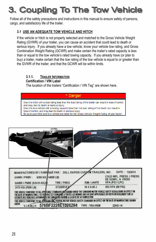
3.1.1. TRAILER INFORMATION Certification / VIN Label The location of the trailers “Certification / VIN Tag” are shown here.
29
The trailer Certification / VIN tag contains the following critical safety information for the use of your trailer: MANUFACTURER: Name of trailer manufacturer DATE OF MANUFACTURE: Month and year the trailer was manufactured. GVWR: The Gross Vehicle Weight Rating is the maximum allowable gross weight of the trailer and its contents. The gross weight of the trailer includes the weight of the trailer and all of the items within it (such as cargo, water, food and other supplies). GAWR: The Gross Axle Weight Rating is the maximum gross weight that an axle can support. It is the lowest of axle, wheel, or tire rating. Sometimes the tire or wheel rating is lower than the axle manufacturers rating, and will then determine GAWR.
The sum total of the GAWR for all trailer axles may be less than the GVWR for the trailer, because some of the trailer load is carried by the tow vehicle, rather than by the trailer axle(s). The total weight of the cargo and trailer must not exceed the GVWR, and the load on an axle must not exceed its GAWR. TIRE SIZE: The tire size recommended for your trailer and load range. PSIC: The “pounds per square inch- cold” is the tire pressure (Kilopascals / Pounds per Square Inch) measured when Cold. CERTIFICATION STATEMENT: “This trailer meets all the Federal Motor Vehicle Safety Standards in effect on the date of manufacture shown above”. VIN: The Vehicle Identification Number. VEHICLE TYPE: Generally the word “trailer” is used. However, after this you may put a Model #, or additional descriptor. Tow Vehicle: When equipping a new vehicle or an older vehicle to tow your trailer, ask the vehicle dealers for advice on how to outfit the towing vehicle. Discuss the following information and equipment with the vehicle dealer. Overall Carrying and Towing Capacity of Vehicle: Vehicle manufacturers will provide you with the maximum towing capacities of their various models, as well as the GCWR. No amount of reinforcement will give a 100 horsepower, 2,500 pound truck the towing capacity that a 300 horsepower, 5,000 pound truck has. Towing Hitch: The towing hitch attached to your tow vehicle must have a capacity equal to or greater than the load rating of the trailer you intend to tow. The hitch capacity must also be matched to the tow vehicle capacity. Suspension System: A tow vehicle equipped with a factory installed “Towing Package” likely comes equipped with heavy duty springs, heavy duty tires and other suspension components which are able to serve the size and weight of the trailer that the vehicle is rated to tow. However, the addition of additional equipment may further improve the tow vehicle performance. These may include adjustable air shocks, helper springs, etc. Brake Controller: The brake controller is part of the tow vehicle and is essential in the operation of the electric brakes on the trailer. If your trailer has electric brakes it requires a brake controller be installed at the driver’s position. The brake controller is not the same as the safety breakaway brake system that is installed on the trailer. Side View Mirrors: The size of the trailer that is being towed and your state law regulations determine the size of the mirrors. However, some states prohibit extended mirrors on a tow vehicle, except while a trailer is actually being towed. In this situation, detachable extended mirrors are necessary. Check with your dealer or the appropriate state agency for mirror requirements. Heavy Duty Flasher: A Heavy Duty Flasher is an electrical component that may be required when your trailer turn signal lights are attached to the tow vehicle flasher circuit.
30
Electrical Connector: An Electrical Connector connects the light and brake systems on the trailer to the light and brake controls on the towing vehicle. Heavy Duty Engine Oil Cooling System: The tow vehicle engine works harder when a trailer is being towed. Depending on the size of the trailer, you may need to install a separate engine oil cooler. Inadequate cooling may result in sudden engine failure. Ask the tow vehicle dealer if it is necessary to install a heavy duty cooling system. Automatic Transmission Oil Cooler: The automatic transmission of a towing vehicle handles more power when a trailer is being towed. Inadequate cooling will shorten transmission life, and may result in sudden transmission failure. Ask the tow vehicle dealer if it is necessary to install a separate oil cooler for the automatic transmission. Fire Extinguisher: It is sensible to have a fire extinguisher in the tow vehicle. Emergency Flares and Emergency Triangle Reflectors: It is wise to carry these warning devices even if you are not towing a trailer. It is particularly important to have these when towing a trailer because the hazard flashers of your towing vehicle will not operate for as long a period of time when the battery is running both the trailer lights and tow vehicle lights.
3.2 COUPLING AND UNCOUPLING THE TRAILER
A secure coupling (or fastening) of the trailer to the tow vehicle is essential. A loss of coupling may result in death or serious injury. Therefore, you must understand and follow all of the instructions for coupling.
The following parts are involved in making a secure coupling between the trailer and tow vehicle: Coupling: That part of the trailer connecting mechanism, by which, the connection is actually made to the trailer hitch. This does not include any structural member, extension of the trailer frame, or brake controller. The following parts are involved in making a secure coupling between the trailer and tow vehicle: Coupling: That part of the trailer connecting mechanism, by which, the connection is actually made to the trailer hitch. This does not include any structural member, extension of the trailer frame, or brake controller. Hitch: That part of the connecting mechanism including the ball support platform and ball and those components that extend and are attached to the towing vehicle, including bumpers intended to serve as hitches.)
Weight Distributing Hitch (or Equalizing Hitch): A mechanical device that connects the trailer to the towing vehicle and by means of leverage applied on both the trailer and towing vehicle structures, when properly adjusted, distributes the imposed vertical load at the hitch and coupling connection between structures of the towing vehicle and trailer.
Weight Carrying Hitch: A mechanical and/or structural device that connects the trailer to the towing vehicle and that does not employ features designed to redistruibute the load imposed at the hitch and carrying connection.
Safety chains or cables: Chains or cables permanently attached to the trailer such that if the coupler connection comes loose, the safety chains or cables can keep the trailer attached to the tow vehicle. With properly rigged safety chains or cables, it is possible to keep the tongue of the trailer from digging into the road pavement, even if the coupler-to-hitch connection comes apart. Some states do not allow safety cables, e.g. Pennsylvania; therefore it may be wise to check with the State Police to see if your state has any restrictions on the use of safety cables, if your trailer is so equipped. Trailer lighting (and braking) connector: A device that connects electrical power from the
31
tow vehicle to the trailer. Electricity is used to turn on brake lights, running lights, and turn signals as required. In addition, if your trailer has a separate braking system, the electrical connector will also supply power to the trailer brakes from the tow vehicle. Breakaway switch: If the trailer becomes de-coupled from the towing vehicle, the breakaway switch lanyard, attached independently to the tow vehicle hitch, will pull a pin in the emergency electrical break-away switch on the trailer. The breakaway switch is activated by a separate battery supply in the trailer such as to energize the trailer brakes independently of the towing vehicle. It is important to check the state of charge of the emergency break-away battery before each trip. Simply pull the pin out of the switch by hand and then try to pull the trailer. If you feel a significant drag force the brakes are activated. Be sure to re-insert the pin in the break-away switch. Also be sure to allow enough slack in the break-away brake lanyard such that the switch will only activate (pin pulls out) if the coupler connection comes loose. For additional details refer to Section 0 Jack: A device on the trailer that is used to raise and lower the trailer tongue. On larger trailers the jack is sometimes called the “landing gear.”
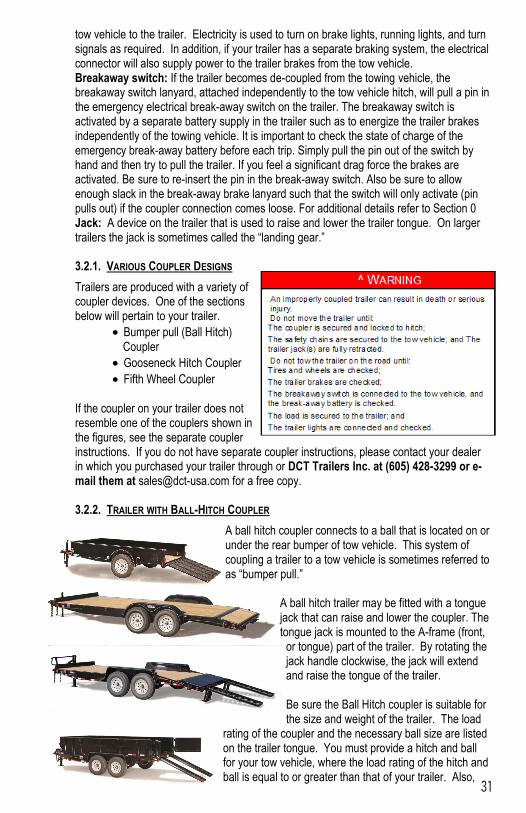
3.2.1. VARIOUS COUPLER DESIGNS
Trailers are produced with a variety of coupler devices. One of the sections below will pertain to your trailer.
Bumper pull (Ball Hitch) Coupler
Gooseneck Hitch Coupler
Fifth Wheel Coupler If the coupler on your trailer does not resemble one of the couplers shown in the figures, see the separate coupler instructions. If you do not have separate coupler instructions, please contact your dealer in which you purchased your trailer through or DCT Trailers Inc. at (605) 428-3299 or e-mail them at [email protected] for a free copy. 3.2.2. TRAILER WITH BALL-HITCH COUPLER
A ball hitch coupler connects to a ball that is located on or under the rear bumper of tow vehicle. This system of coupling a trailer to a tow vehicle is sometimes referred to as “bumper pull.”
A ball hitch trailer may be fitted with a tongue jack that can raise and lower the coupler. The tongue jack is mounted to the A-frame (front,
or tongue) part of the trailer. By rotating the jack handle clockwise, the jack will extend and raise the tongue of the trailer. Be sure the Ball Hitch coupler is suitable for the size and weight of the trailer. The load
rating of the coupler and the necessary ball size are listed on the trailer tongue. You must provide a hitch and ball for your tow vehicle, where the load rating of the hitch and ball is equal to or greater than that of your trailer. Also,
32
the ball size must be the same as the coupler size. If the hitch ball is too small, too large, is underrated, is loose or is worn, the trailer can come loose from the tow vehicle, and may cause death or serious injury. THE TOW VEHICLE, HITCH AND BALL MUST HAVE A RATED TOWING CAPACITY EQUAL TO OR GREATER THAN THE TRAILER GROSS VEHICLE WEIGHT RATING (GVWR). **IT IS ESSENTIAL THAT THE HITCH BALL BE OF THE SAME SIZE AS THE COUPLER.** The ball size and load rating (capacity) are marked on the ball; hitch capacity is marked on the hitch.
3.2.2.1. Before coupling the trailer to the tow vehicle
Be sure the size and rating of hitch ball match the size and rating of the coupler. Hitch balls and couplers are marked with their size and rating.
Wipe the hitch ball clean and inspect it visually and by feel for flat spots, cracks and pits.
Rock the ball to make sure it is tight to the hitch. Then you will need to visually check and see that the hitch ball nut is solid against the lock washer and hitch frame.
Wipe the inside and outside of the coupler clean and inspect it visually for cracks and deformations; feel the inside of the coupler for worn spots and pits.
Be sure the coupler is tight to the tongue of the trailer. All coupler fasteners must be visibly solid against the trailer frame.
Rai
se the bottom surface of the coupler to be above the top of
33
the hitch ball. Use the jack if one is provided; otherwise, use wood or concrete blocks to support the trailer tongue.
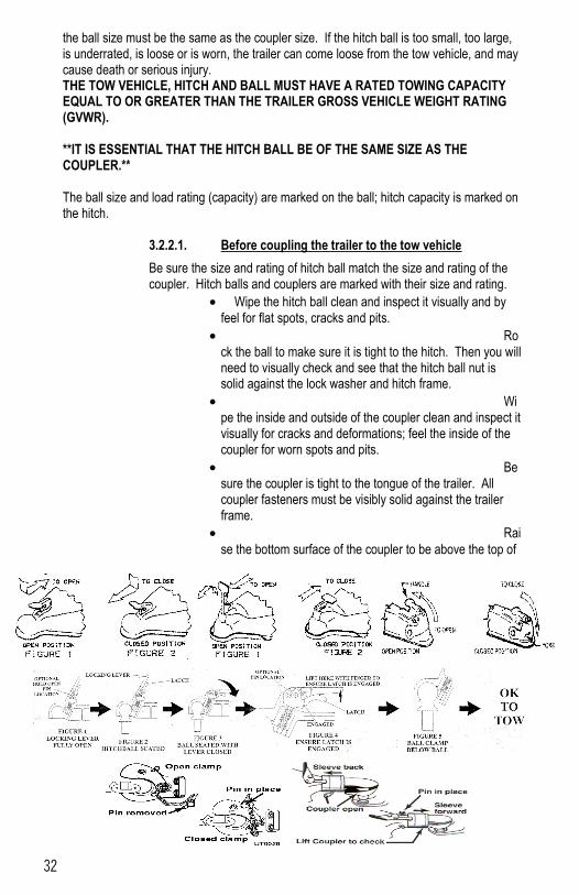
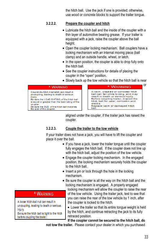
3.2.2.2. Prepare the coupler and hitch
Lubricate the hitch ball and the inside of the coupler with a thin layer of automotive bearing grease. If your trailer is equipped with a jack, raise the coupler above the ball height.
Open the coupler locking mechanism. Ball couplers have a locking mechanism with an internal moving piece (ball clamp) and an outside handle, wheel, or latch.
In the open position, the coupler is able to drop fully onto the hitch ball.
See the coupler instructions for details of placing the coupler in the “open” position.
Slowly back up the tow vehicle so that the hitch ball is near or
aligned under the coupler, if the trailer jack has raised the coupler.
3.2.2.3. Couple the trailer to the tow vehicle
If your trailer does not have a jack, you will have to lift the coupler and place it over the ball.
If you have a jack, lower the trailer tongue until the coupler fully engages the hitch ball. If the coupler does not line up with the hitch ball, adjust the position of the tow vehicle.
Engage the coupler locking mechanism. In the engaged position, the locking mechanism securely holds the coupler to the hitch ball.
Insert a pin or lock through the hole in the locking mechanism.
Be sure the coupler is all the way on the hitch ball and the locking mechanism is engaged. A properly engaged
locking mechanism will allow the coupler to raise the rear of the tow vehicle. Using the trailer jack, test to see that you can raise the rear of the tow vehicle by 1 inch, after the coupler is locked to the hitch.
Lower the trailer so that its entire tongue weight is held by the hitch, and continue retracting the jack to its fully retraced position. If the coupler cannot be secured to the hitch ball, do
not tow the trailer. Please contact your dealer in which you purchased
34
your trailer through or DCT Trailers Inc. at (605) 428-3299 or e-mail them at [email protected] for assistance. 3.2.2.4. Rig the safety chains
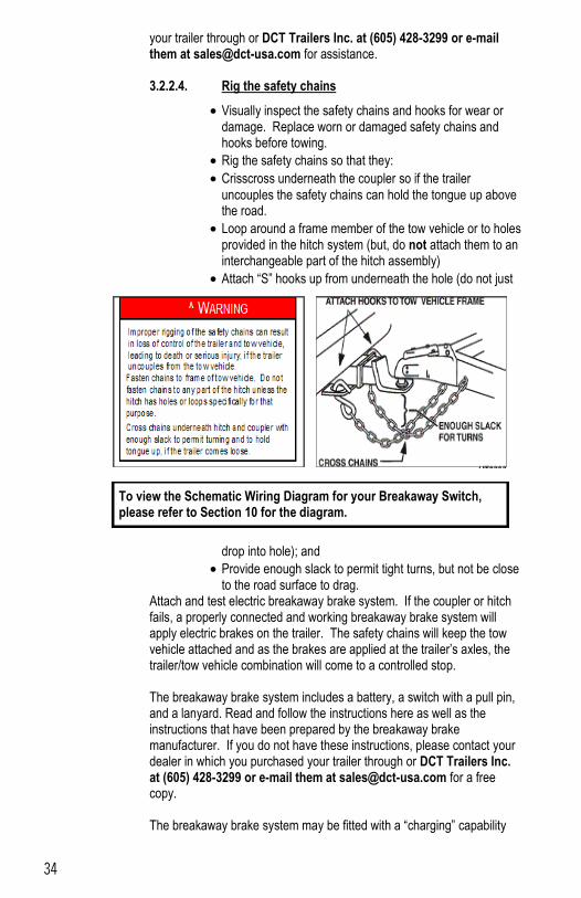
Visually inspect the safety chains and hooks for wear or damage. Replace worn or damaged safety chains and hooks before towing.
Rig the safety chains so that they:
Crisscross underneath the coupler so if the trailer
uncouples the safety chains can hold the tongue up above the road.
Loop around a frame member of the tow vehicle or to holes provided in the hitch system (but, do not attach them to an interchangeable part of the hitch assembly)
Attach “S” hooks up from underneath the hole (do not just
drop into hole); and
Provide enough slack to permit tight turns, but not be close to the road surface to drag.
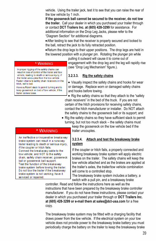
Attach and test electric breakaway brake system. If the coupler or hitch fails, a properly connected and working breakaway brake system will apply electric brakes on the trailer. The safety chains will keep the tow vehicle attached and as the brakes are applied at the trailer’s axles, the trailer/tow vehicle combination will come to a controlled stop. The breakaway brake system includes a battery, a switch with a pull pin, and a lanyard. Read and follow the instructions here as well as the instructions that have been prepared by the breakaway brake manufacturer. If you do not have these instructions, please contact your dealer in which you purchased your trailer through or DCT Trailers Inc. at (605) 428-3299 or e-mail them at [email protected] for a free copy. The breakaway brake system may be fitted with a “charging” capability
To view the Schematic Wiring Diagram for your Breakaway Switch, please refer to Section 10 for the diagram.
35
that draws power from the tow vehicle. If the electrical system on your tow vehicle does not provide power to the breakaway brake battery, you must periodically charge the battery to keep the breakaway brake system in working order.
Connect the pullpin lanyard to the tow vehicle so that the pullpin will be pulled out before all of the slack in the safety chains is taken up (see Breakaway Brake System figure). Do not connect the pullpin cable to a safety chain or to the hitch ball or hitch ball assembly. This would keep the breakaway brake system from operating when it is needed.
To test the break-away brake battery, remove the pullpin from the switch and attempt to pull the trailer forward. You should feel the trailer resisting being towed, but the wheels will not necessarily be locked. If the brakes do not function, do not tow the trailer until brakes, or battery, are repaired.
Immediately replace the pull pin. The breakaway brake system battery discharges rapidly when the pull pin is removed.
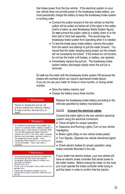
Do not tow the trailer with the breakaway brake system ON because the brakes will overheat which can result in permanent brake failure. If you do not use your trailer for three or more months, or during winter months:
Store the battery indoors; and
Charge the battery every three months. Replace the breakaway brake battery according to the intervals specified by battery manufacturer. 3.2.2.5. Connect the electrical cables
Connect the trailer lights to the tow vehicle's electrical system using the electrical connectors.
Check all lights for proper operation.
Clearance and Running Lights (Turn on tow vehicle
headlights).
Brake Lights (Step on tow vehicle brake pedal).
Turn Signals. (Operate tow vehicle directional signal lever).
Check electric brakes for proper operation using
brake controller Mounted in the cab. If your trailer has electric brakes, your tow vehicle will have an electric brake controller that sends power to the trailer brakes. Before towing the trailer on the road, you must operate the brake controller while trying to pull the trailer in order to confirm that the electric
36
brakes operate. While towing the trailer at less than 5 M.P.H., manually operate the electric brake controller in the tow vehicle cab. You should feel the operation of the trailer brakes. 3.2.2.6. Uncoupling the Ball Hitch Trailer with Tongue Jack
Follow these steps to uncouple your ball hitch trailer from the tow vehicle:
Block trailer tires to prevent the trailer from rolling, before
jacking the trailer up.
Disconnect the electrical connector.
Disconnect the breakaway brake switch lanyard.
Disconnect the safety chains from the tow vehicle.
Unlock the coupler and open it.
Before extending jack, make certain the ground surface below the jack pad will support the tongue load.
Rotate the jack handle (or crank) clockwise. This will slowly extend the jack and transfer the weight of the trailer tongue to the jack.
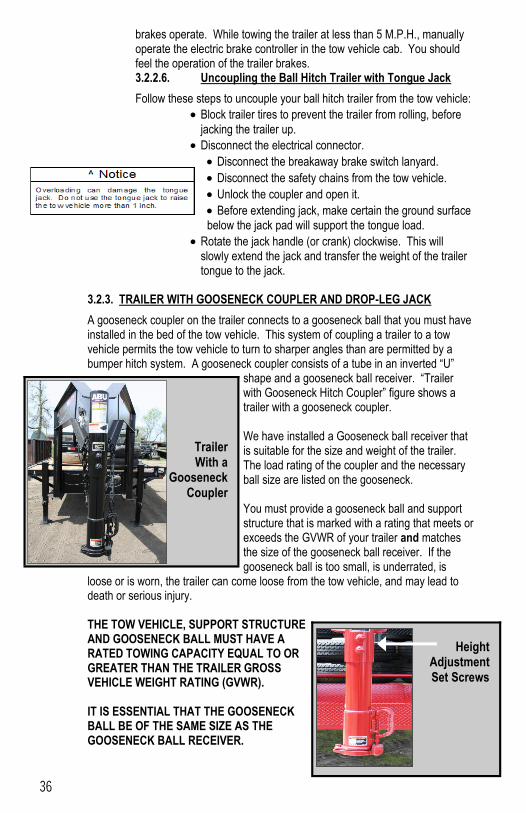
3.2.3. TRAILER WITH GOOSENECK COUPLER AND DROP-LEG JACK
A gooseneck coupler on the trailer connects to a gooseneck ball that you must have installed in the bed of the tow vehicle. This system of coupling a trailer to a tow vehicle permits the tow vehicle to turn to sharper angles than are permitted by a bumper hitch system. A gooseneck coupler consists of a tube in an inverted “U”
shape and a gooseneck ball receiver. “Trailer with Gooseneck Hitch Coupler” figure shows a trailer with a gooseneck coupler. We have installed a Gooseneck ball receiver that is suitable for the size and weight of the trailer. The load rating of the coupler and the necessary ball size are listed on the gooseneck. You must provide a gooseneck ball and support structure that is marked with a rating that meets or exceeds the GVWR of your trailer and matches the size of the gooseneck ball receiver. If the gooseneck ball is too small, is underrated, is
loose or is worn, the trailer can come loose from the tow vehicle, and may lead to death or serious injury. THE TOW VEHICLE, SUPPORT STRUCTURE AND GOOSENECK BALL MUST HAVE A RATED TOWING CAPACITY EQUAL TO OR GREATER THAN THE TRAILER GROSS VEHICLE WEIGHT RATING (GVWR). IT IS ESSENTIAL THAT THE GOOSENECK BALL BE OF THE SAME SIZE AS THE GOOSENECK BALL RECEIVER.
Height
Adjustment Set Screws
Trailer With a
Gooseneck Coupler
37
The ball size and load rating (capacity) are marked on the ball; hitch capacity is marked on the hitch. The height of the ball receiver on the trailer must be adjusted to match the height of the gooseneck ball on your tow vehicle, so that:
There is clearance between the bottom of the trailer and the sides of the tow vehicle bed
The trailer is level and allows equal weight distribution on tandem axles.
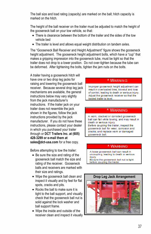
The “Gooseneck Ball Receiver and Height Adjustment” figure shows the gooseneck height adjustment. The gooseneck height adjustment bolts, which have a “cup” that makes a gripping impression into the gooseneck tube, must be tight so that the trailer does not drop to a lower position. Do not over-tighten because the tube can be deformed. After tightening the bolts, tighten the jam nuts on the bolts.
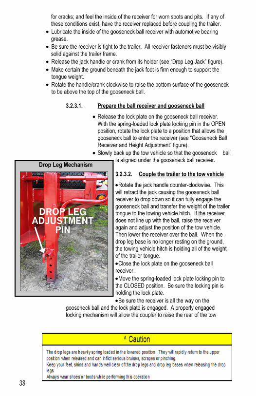
A trailer having a gooseneck hitch will have one or two drop leg jacks for raising and lowering the gooseneck ball receiver. Because several drop leg jack mechanisms are available, the general instructions below may vary slightly from the jack manufacturer’s instructions. If the trailer jack on your trailer does not resemble the jack shown in the figures, follow the jack instructions provided by the jack manufacturer. If you do not have these instructions, please contact your dealer in which you purchased your trailer through or DCT Trailers Inc. at (605) 428-3299 or e-mail them at [email protected] for a free copy. Before attempting to tow the trailer:
Be sure the size and rating of the gooseneck ball match the size and rating of the receiver. Gooseneck balls and receivers are marked with their size and ratings.
Wipe the gooseneck ball clean and inspect it visually and by feel for flat spots, cracks and pits.
Rocks the ball to make sure it is tight to the ball support, and visually check that the gooseneck ball nut is solid against the lock washer and ball support frame.
Wipe the inside and outside of the receiver clean and inspect it visually
Drop Leg Jack Arrangement
38
for cracks; and feel the inside of the receiver for worn spots and pits. If any of these conditions exist, have the receiver replaced before coupling the trailer.
Lubricate the inside of the gooseneck ball receiver with automotive bearing grease.
Be sure the receiver is tight to the trailer. All receiver fasteners must be visibly solid against the trailer frame.
Release the jack handle or crank from its holder (see “Drop Leg Jack” figure).
Make certain the ground beneath the jack foot is firm enough to support the tongue weight.
Rotate the handle/crank clockwise to raise the bottom surface of the gooseneck to be above the top of the gooseneck ball.
3.2.3.1. Prepare the ball receiver and gooseneck ball
Release the lock plate on the gooseneck ball receiver.
With the spring-loaded lock plate locking pin in the OPEN position, rotate the lock plate to a position that allows the gooseneck ball to enter the receiver (see “Gooseneck Ball Receiver and Height Adjustment” figure).
Slowly back up the tow vehicle so that the gooseneck ball is aligned under the gooseneck ball receiver. 3.2.3.2. Couple the trailer to the tow vehicle
Rotate the jack handle counter-clockwise. This will retract the jack causing the gooseneck ball receiver to drop down so it can fully engage the gooseneck ball and transfer the weight of the trailer tongue to the towing vehicle hitch. If the receiver does not line up with the ball, raise the receiver again and adjust the position of the tow vehicle. Then lower the receiver over the ball. When the drop leg base is no longer resting on the ground, the towing vehicle hitch is holding all of the weight of the trailer tongue.
Close the lock plate on the gooseneck ball receiver.
Move the spring-loaded lock plate locking pin to the CLOSED position. Be sure the locking pin is holding the lock plate.
Be sure the receiver is all the way on the gooseneck ball and the lock plate is engaged. A properly engaged locking mechanism will allow the coupler to raise the rear of the tow
Drop Leg Mechanism
DROP LEG ADJUSTMENT
PIN
39
vehicle. Using the trailer jack, test it to see that you can raise the rear of the tow vehicle by 1 inch. If the gooseneck ball cannot be secured to the receiver, do not tow the trailer. Call your dealer in which you purchased your trailer through or contact DCT Trailers Inc. at (605) 428-3299 for assistance. For additional information on the Drop Leg Jacks, please refer to the “Diagram Section” for additional diagrams.
After testing to see that the receiver is properly secured and locked to the ball, retract the jack to its fully retracted position.
Return the drop legs to their upper positions. The drop legs are held in the lowered position with a plunger pin. Rotating the plunger pin while
pulling it outward will cause it to come out of engagement with the drop leg and the leg will rapidly rise (see “Drop Leg Mechanism” figure.). 3.2.3.3. Rig the safety chains
Visually inspect the safety chains and hooks for wear or damage. Replace worn or damaged safety chains and hooks before towing.
Rig the safety chains so that they attach to the “safety chain receivers” in the bed of the truck. If you are not certain of the hitch provisions for receiving safety chains, contact the hitch manufacturer or installer. Do NOT attach the safety chains to the gooseneck ball or its support; and
Rig the safety chains so they have sufficient slack to permit
turning, but not too much slack – the safety chains must keep the gooseneck on the tow vehicle bed if the trailer uncouples. 3.2.3.4. Attach and test the breakaway brake system
If the coupler or hitch fails, a properly connected and working breakaway brake system will apply electric brakes on the trailer. The safety chains will keep the tow vehicle attached and as the brakes are applied at the trailer’s axles, the trailer/tow vehicle combination will come to a controlled stop. The breakaway brake system includes a battery, a switch with a pull pin, and a breakaway brake
controller. Read and follow the instructions here as well as the instructions that have been prepared by the breakaway brake controller manufacturer. If you do not have these instructions, please contact your dealer in which you purchased your trailer through or DCT Trailers Inc. at (605) 428-3299 or e-mail them at [email protected] for a free copy. The breakaway brake system may be fitted with a charging facility that draws power from the tow vehicle. If the electrical system on your tow vehicle does not provide power to the breakaway brake battery you must periodically charge the battery on the trailer to keep the breakaway brake
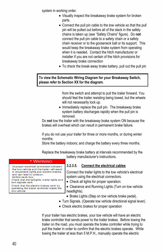
40
system in working order.
Visually inspect the breakaway brake system for broken parts.
Connect the pull pin cable to the tow vehicle so that the pull pin will be pulled out before all of the slack in the safety chains is taken up (see “Safety Chains” figure). Do not connect the pull pin cable to a safety chain or a safety chain receiver or to the gooseneck ball or its support. This would keep the breakaway brake system from operating when it is needed. Contact the hitch manufacturer or installer if you are not certain of the hitch provisions for breakaway brake connection
To check the break-away brake battery, pull out the pull pin
from the switch and attempt to pull the trailer forward. You should feel the trailer resisting being towed, but the wheels will not necessarily lock up.
Immediately replace the pull pin. The breakaway brake system battery discharges rapidly when the pull pin is removed.
Do not tow the trailer with the breakaway brake system ON because the brakes will overheat which can result in permanent brake failure. If you do not use your trailer for three or more months, or during winter months: Store the battery indoors; and charge the battery every three months. Replace the breakaway brake battery at intervals recommended by the
battery manufacturer’s instructions. 3.2.3.5. Connect the electrical cables
Connect the trailer lights to the tow vehicle's electrical system using the electrical connectors.
Check all lights for proper operation:
Clearance and Running Lights (Turn on tow vehicle
headlights).
Brake Lights (Step on tow vehicle brake pedal).
Turn Signals. (Operate tow vehicle directional signal lever).
Check electric brakes for proper operation If your trailer has electric brakes, your tow vehicle will have an electric brake controller that sends power to the trailer brakes. Before towing the trailer on the road, you must operate the brake controller while trying to pull the trailer in order to confirm that the electric brakes operate. While towing the trailer at less than 5 M.P.H., manually operate the electric
To view the Schematic Wiring Diagram for your Breakaway Switch, please refer to Section XX for the diagram.
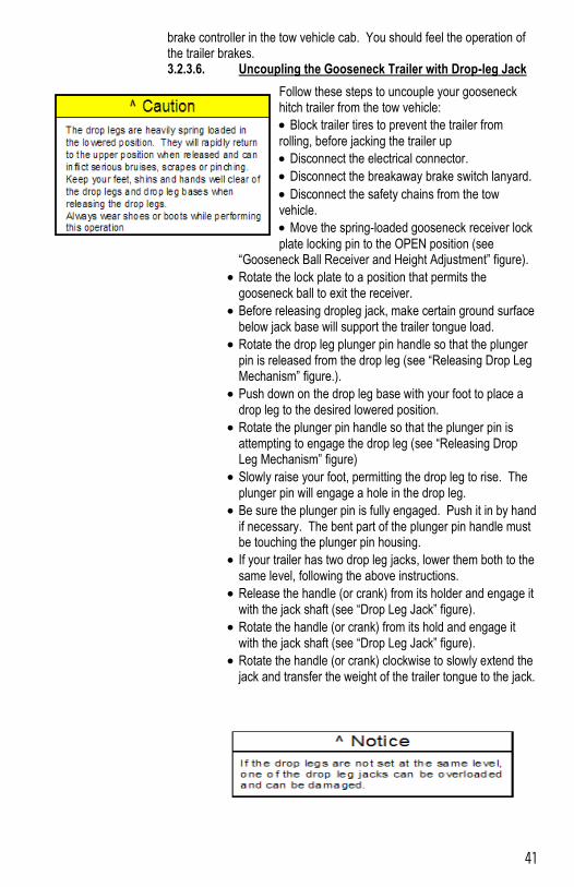
41
brake controller in the tow vehicle cab. You should feel the operation of the trailer brakes. 3.2.3.6. Uncoupling the Gooseneck Trailer with Drop-leg Jack
Follow these steps to uncouple your gooseneck hitch trailer from the tow vehicle:
Block trailer tires to prevent the trailer from
rolling, before jacking the trailer up
Disconnect the electrical connector.
Disconnect the breakaway brake switch lanyard.
Disconnect the safety chains from the tow vehicle.
Move the spring-loaded gooseneck receiver lock
plate locking pin to the OPEN position (see “Gooseneck Ball Receiver and Height Adjustment” figure).
Rotate the lock plate to a position that permits the gooseneck ball to exit the receiver.
Before releasing dropleg jack, make certain ground surface below jack base will support the trailer tongue load.
Rotate the drop leg plunger pin handle so that the plunger pin is released from the drop leg (see “Releasing Drop Leg Mechanism” figure.).
Push down on the drop leg base with your foot to place a drop leg to the desired lowered position.
Rotate the plunger pin handle so that the plunger pin is attempting to engage the drop leg (see “Releasing Drop Leg Mechanism” figure)
Slowly raise your foot, permitting the drop leg to rise. The plunger pin will engage a hole in the drop leg.
Be sure the plunger pin is fully engaged. Push it in by hand if necessary. The bent part of the plunger pin handle must be touching the plunger pin housing.
If your trailer has two drop leg jacks, lower them both to the same level, following the above instructions.
Release the handle (or crank) from its holder and engage it with the jack shaft (see “Drop Leg Jack” figure).
Rotate the handle (or crank) from its hold and engage it with the jack shaft (see “Drop Leg Jack” figure).
Rotate the handle (or crank) clockwise to slowly extend the jack and transfer the weight of the trailer tongue to the jack.
42
On two speed jacks, pushing the handle shaft toward the gearbox can perform rapid extension. This shifts the gearbox into a high speed mode.
When the drop leg base contacts the ground, shift the gearbox into low gear mode by pulling or pushing on the handle shaft until it locks into low gear.
Continue to extend the jack(s), making sure that the ground is providing stable and level support for the trailer.
After the jack(s) are extended and the gooseneck ball
receiver is well clear of the gooseneck ball, to permit driving the tow vehicle away, disengage the handle from its shaft and return to its holder.
3.2.4. TRAILER WITH FIFTH-WHEEL COUPLER AND DROP-LEG JACK
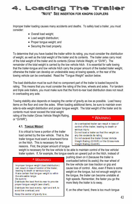
43
*NOTE* SEE INSERTION FOR KINGPIN COUPLERS
Improper trailer loading causes many accidents and deaths. To safely load a trailer, you must consider:
Overall load weight;
Load weight distribution;
Proper tongue weight; and
Securing the load properly.
To determine that you have loaded the trailer within its rating, you must consider the distribution of weight, as well as the total weight of the trailer and its contents. The trailer axles carry most of the total weight of the trailer and its contents (Gross Vehicle Weight, or “GVW”). The remainder of the total weight is carried by the tow vehicle hitch. It is essential for safe towing that the trailer-tongue and tow vehicle hitch carry the proper amount of the loaded trailer weight, otherwise the trailer can develop an undesirable sway at towing speeds, or the rear of the towing vehicle can be overloaded. Read the “Tongue Weight” section below. The load distribution must be such that no component part of the trailer is loaded beyond its rating. This means that you must consider the rating of the tires, wheels and axles. For tandem and triple axle trailers, you must make sure that the front-to-rear load distribution does not result in overloading any axle. Towing stability also depends on keeping the center of gravity as low as possible. Load heavy items on the floor and over the axles. When loading additional items, be sure to maintain even side-to-side weight distribution and proper tongue weight. The total weight of the trailer and its contents must never exceed the total weight rating of the trailer (Gross Vehicle Weight Rating, or “GVWR”).
4.1. TONGUE WEIGHT
It is critical to have a portion of the trailer load carried by the tow vehicle. That is, the trailer tongue must exert a downward force on the hitch. This is necessary for two reasons. First, the proper amount of tongue weight is necessary for the tow vehicle to be able to maintain control of the tow vehicle/trailer system. If, for example, the tongue exerts an upward pull on the hitch, instead of
pushing down on it (because the trailer is overloaded behind its axels)) the rear wheel of the tow vehicle can lose traction or grip and cause loss of control. Also, even if there is some weight on the tongue, but not enough weight on the tongue, the trailer can become unstable at high speeds. Remember, the faster you go the more likely the trailer is to sway. If, on the other hand, there is too much tongue
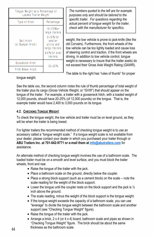
44
weight, the tow vehicle is prone to jack-knife (like the old Corvairs). Furthermore, the front wheels of the tow vehicle can be too lightly loaded and cause loss of steering control and traction, if the front wheels are driving. In addition to tow vehicle control, tongue weight is necessary to insure that the trailer axels) do not exceed their Gross Axle Weight Rating (GAWR). The table to the right has “rules of thumb” for proper
tongue weight. See the table xxx, the second column notes the rule of thumb percentage of total weight of the trailer plus its cargo (Gross Vehicle Weight, or “GVW”) that should appear on the tongue of the trailer. For example, a trailer with a gooseneck hitch, with a loaded weight of 12,000 pounds, should have 20-25% (of 12,000 pounds) on the tongue. That is, the example trailer would have 2,400 to 3,000 pounds on its tongue. 4.2. CHECKING TONGUE WEIGHT
To check the tongue weight, the tow vehicle and trailer must be on level ground, as they will be when the trailer is being towed. For lighter trailers the recommended method of checking tongue weight is to use an accessory called a “tongue weight scale.” If a tongue weight scale is not available from your dealer, please contact your dealer in which you purchased your trailer through or ABU Trailers Inc. at 701-642-9771 or e-mail them at [email protected] for assistance. An alternate method of checking tongue weight involves the use of a bathroom scale. The loaded trailer must be on a smooth and level surface, and you must block the trailer wheels, front and rear.
Raise the tongue of the trailer with the jack.
Place a bathroom scale on the ground, directly below the coupler.
Place a strong block support (such as a cement block) on the scale – note the scale reading for the weight of the block support.
Lower the tongue until the coupler rests on the block support and the jack is ½
inch above the ground.
The scale reading, minus the weight of the block support is the tongue weight.
If the tongue weight exceeds the capacity of a bathroom scale, you can use
“leverage” to divide the tongue weight between the bathroom scale and another support (see “Checking Tongue Weight” figure).
Raise the tongue of the trailer with the jack.
Arrange a brick, 2 x 4 (or 4 x 4) board, bathroom scale and pipes as shown in “Checking Tongue Weight” figure. The brick should be about the same thickness as the bathroom scale.
The numbers quoted to the left are for example purposes only and should be tailored to the specific trailer. For questions regarding the actual percent of tongue weight for the trailer, check with the manufacturer for specifics.
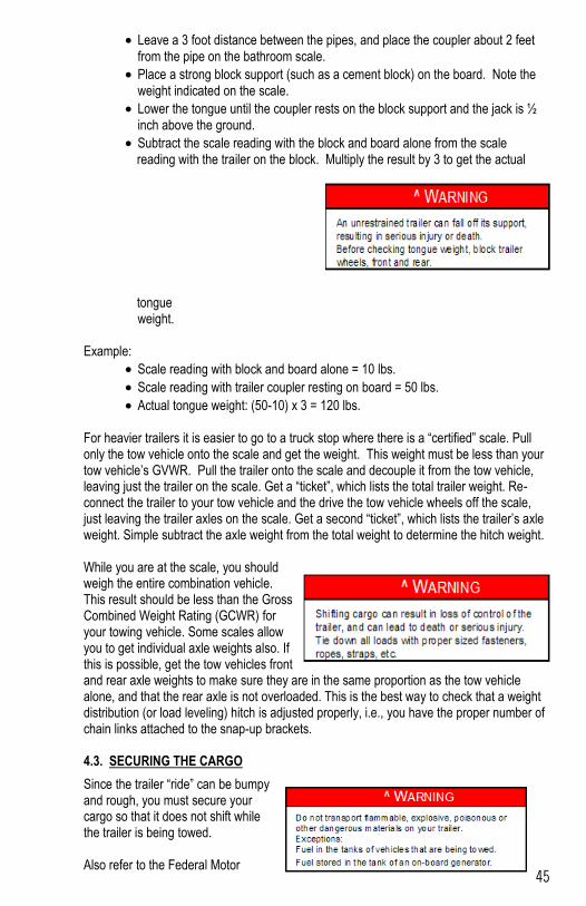
45
Leave a 3 foot distance between the pipes, and place the coupler about 2 feet from the pipe on the bathroom scale.
Place a strong block support (such as a cement block) on the board. Note the weight indicated on the scale.
Lower the tongue until the coupler rests on the block support and the jack is ½ inch above the ground.
Subtract the scale reading with the block and board alone from the scale reading with the trailer on the block. Multiply the result by 3 to get the actual
tongue weight.
Example:
Scale reading with block and board alone = 10 lbs.
Scale reading with trailer coupler resting on board = 50 lbs.
Actual tongue weight: (50-10) x 3 = 120 lbs. For heavier trailers it is easier to go to a truck stop where there is a “certified” scale. Pull only the tow vehicle onto the scale and get the weight. This weight must be less than your tow vehicle’s GVWR. Pull the trailer onto the scale and decouple it from the tow vehicle, leaving just the trailer on the scale. Get a “ticket”, which lists the total trailer weight. Re-connect the trailer to your tow vehicle and the drive the tow vehicle wheels off the scale, just leaving the trailer axles on the scale. Get a second “ticket”, which lists the trailer’s axle weight. Simple subtract the axle weight from the total weight to determine the hitch weight. While you are at the scale, you should weigh the entire combination vehicle. This result should be less than the Gross Combined Weight Rating (GCWR) for your towing vehicle. Some scales allow you to get individual axle weights also. If this is possible, get the tow vehicles front and rear axle weights to make sure they are in the same proportion as the tow vehicle alone, and that the rear axle is not overloaded. This is the best way to check that a weight distribution (or load leveling) hitch is adjusted properly, i.e., you have the proper number of chain links attached to the snap-up brackets. 4.3. SECURING THE CARGO
Since the trailer “ride” can be bumpy and rough, you must secure your cargo so that it does not shift while the trailer is being towed. Also refer to the Federal Motor
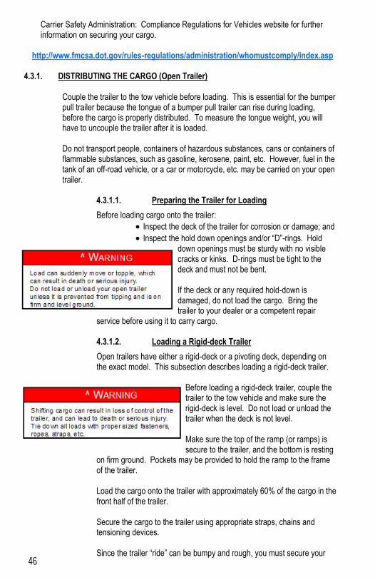
46
Carrier Safety Administration: Compliance Regulations for Vehicles website for further information on securing your cargo.
http://www.fmcsa.dot.gov/rules-regulations/administration/whomustcomply/index.asp
4.3.1. DISTRIBUTING THE CARGO (Open Trailer) Couple the trailer to the tow vehicle before loading. This is essential for the bumper pull trailer because the tongue of a bumper pull trailer can rise during loading, before the cargo is properly distributed. To measure the tongue weight, you will have to uncouple the trailer after it is loaded. Do not transport people, containers of hazardous substances, cans or containers of flammable substances, such as gasoline, kerosene, paint, etc. However, fuel in the tank of an off-road vehicle, or a car or motorcycle, etc. may be carried on your open trailer.
4.3.1.1. Preparing the Trailer for Loading
Before loading cargo onto the trailer:
Inspect the deck of the trailer for corrosion or damage; and
Inspect the hold down openings and/or “D”-rings. Hold down openings must be sturdy with no visible cracks or kinks. D-rings must be tight to the deck and must not be bent. If the deck or any required hold-down is damaged, do not load the cargo. Bring the trailer to your dealer or a competent repair
service before using it to carry cargo. 4.3.1.2. Loading a Rigid-deck Trailer
Open trailers have either a rigid-deck or a pivoting deck, depending on the exact model. This subsection describes loading a rigid-deck trailer.
Before loading a rigid-deck trailer, couple the trailer to the tow vehicle and make sure the rigid-deck is level. Do not load or unload the trailer when the deck is not level. Make sure the top of the ramp (or ramps) is secure to the trailer, and the bottom is resting
on firm ground. Pockets may be provided to hold the ramp to the frame of the trailer. Load the cargo onto the trailer with approximately 60% of the cargo in the front half of the trailer. Secure the cargo to the trailer using appropriate straps, chains and tensioning devices. Since the trailer “ride” can be bumpy and rough, you must secure your
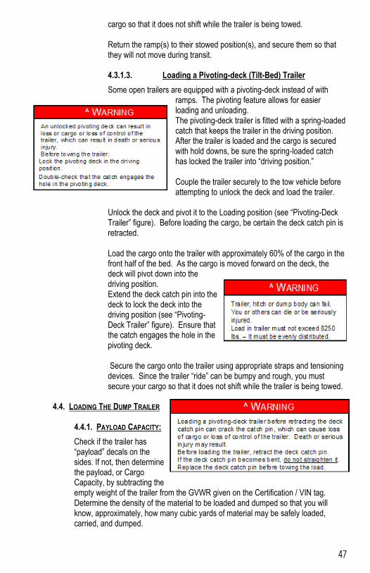
47
cargo so that it does not shift while the trailer is being towed. Return the ramp(s) to their stowed position(s), and secure them so that they will not move during transit. 4.3.1.3. Loading a Pivoting-deck (Tilt-Bed) Trailer
Some open trailers are equipped with a pivoting-deck instead of with ramps. The pivoting feature allows for easier loading and unloading. The pivoting-deck trailer is fitted with a spring-loaded catch that keeps the trailer in the driving position. After the trailer is loaded and the cargo is secured with hold downs, be sure the spring-loaded catch has locked the trailer into “driving position.” Couple the trailer securely to the tow vehicle before attempting to unlock the deck and load the trailer.
Unlock the deck and pivot it to the Loading position (see “Pivoting-Deck Trailer” figure). Before loading the cargo, be certain the deck catch pin is retracted. Load the cargo onto the trailer with approximately 60% of the cargo in the front half of the bed. As the cargo is moved forward on the deck, the deck will pivot down into the driving position. Extend the deck catch pin into the deck to lock the deck into the driving position (see “Pivoting-Deck Trailer” figure). Ensure that the catch engages the hole in the pivoting deck. Secure the cargo onto the trailer using appropriate straps and tensioning devices. Since the trailer “ride” can be bumpy and rough, you must secure your cargo so that it does not shift while the trailer is being towed.
4.4. LOADING THE DUMP TRAILER
4.4.1. PAYLOAD CAPACITY:
Check if the trailer has “payload” decals on the sides. If not, then determine the payload, or Cargo Capacity, by subtracting the empty weight of the trailer from the GVWR given on the Certification / VIN tag. Determine the density of the material to be loaded and dumped so that you will know, approximately, how many cubic yards of material may be safely loaded, carried, and dumped.
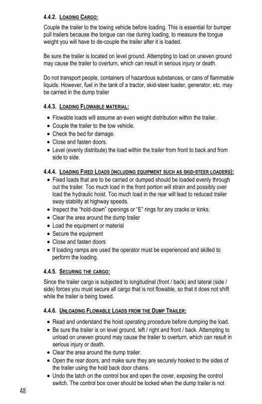
48
4.4.2. LOADING CARGO:
Couple the trailer to the towing vehicle before loading. This is essential for bumper pull trailers because the tongue can rise during loading, to measure the tongue weight you will have to de-couple the trailer after it is loaded. Be sure the trailer is located on level ground. Attempting to load on uneven ground may cause the trailer to overturn, which can result in serious injury or death. Do not transport people, containers of hazardous substances, or cans of flammable liquids. However, fuel in the tank of a tractor, skid-steer loader, generator, etc. may be carried in the dump trailer 4.4.3. LOADING FLOWABLE MATERIAL:
Flowable loads will assume an even weight distribution within the trailer.
Couple the trailer to the tow vehicle.
Check the bed for damage.
Close and fasten doors.
Level (evenly distribute) the load within the trailer from front to back and from side to side.
4.4.4. LOADING FIXED LOADS (INCLUDING EQUIPMENT SUCH AS SKID-STEER LOADERS):
Fixed loads that are to be carried or dumped should be loaded evenly through out the trailer. Too much load in the front portion will strain and possibly over load the hydraulic hoist. Too much load in the rear will lead to reduced trailer sway stability at highway speeds.
Inspect the “hold-down” openings or “E” rings for any cracks or kinks.
Clear the area around the dump trailer
Load the equipment or material
Secure the equipment
Close and fasten doors
If loading ramps are used the operator must be experienced and skilled to
perform the loading.
4.4.5. SECURING THE CARGO:
Since the trailer cargo is subjected to longitudinal (front / back) and lateral (side / side) forces you must secure all cargo that is not flowable, so that it does not shift while the trailer is being towed. 4.4.6. UNLOADING FLOWABLE LOADS FROM THE DUMP TRAILER:
Read and understand the hoist operating procedure before dumping the load.
Be sure the trailer is on level ground, left / right and front / back. Attempting to unload on uneven ground may cause the trailer to overturn, which can result in serious injury or death.
Clear the area around the dump trailer.
Open the rear doors, and make sure they are securely hooked to the sides of the trailer using the hold back door chains.
Undo the latch on the control box and open the cover, exposing the control switch. The control box cover should be locked when the dump trailer is not
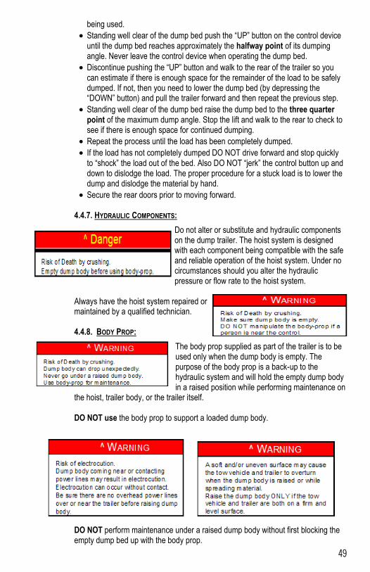
49
being used.
Standing well clear of the dump bed push the “UP” button on the control device until the dump bed reaches approximately the halfway point of its dumping angle. Never leave the control device when operating the dump bed.
Discontinue pushing the “UP” button and walk to the rear of the trailer so you can estimate if there is enough space for the remainder of the load to be safely dumped. If not, then you need to lower the dump bed (by depressing the “DOWN” button) and pull the trailer forward and then repeat the previous step.
Standing well clear of the dump bed raise the dump bed to the three quarter point of the maximum dump angle. Stop the lift and walk to the rear to check to see if there is enough space for continued dumping.
Repeat the process until the load has been completely dumped.
If the load has not completely dumped DO NOT drive forward and stop quickly to “shock” the load out of the bed. Also DO NOT “jerk” the control button up and down to dislodge the load. The proper procedure for a stuck load is to lower the dump and dislodge the material by hand.
Secure the rear doors prior to moving forward. 4.4.7. HYDRAULIC COMPONENTS:
Do not alter or substitute and hydraulic components on the dump trailer. The hoist system is designed with each component being compatible with the safe and reliable operation of the hoist system. Under no circumstances should you alter the hydraulic pressure or flow rate to the hoist system.
Always have the hoist system repaired or maintained by a qualified technician. 4.4.8. BODY PROP:
The body prop supplied as part of the trailer is to be used only when the dump body is empty. The purpose of the body prop is a back-up to the hydraulic system and will hold the empty dump body in a raised position while performing maintenance on
the hoist, trailer body, or the trailer itself. DO NOT use the body prop to support a loaded dump body.
DO NOT perform maintenance under a raised dump body without first blocking the empty dump bed up with the body prop.
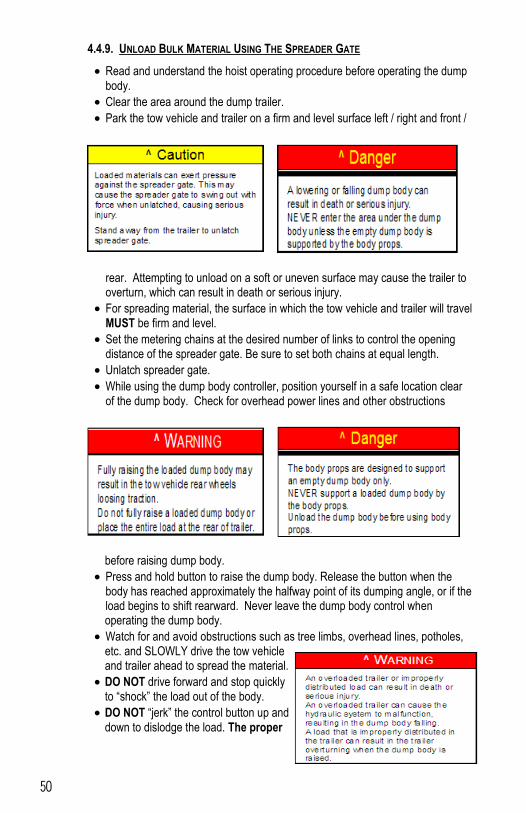
50
4.4.9. UNLOAD BULK MATERIAL USING THE SPREADER GATE
Read and understand the hoist operating procedure before operating the dump body.
Clear the area around the dump trailer.
Park the tow vehicle and trailer on a firm and level surface left / right and front /
rear. Attempting to unload on a soft or uneven surface may cause the trailer to overturn, which can result in death or serious injury.
For spreading material, the surface in which the tow vehicle and trailer will travel MUST be firm and level.
Set the metering chains at the desired number of links to control the opening distance of the spreader gate. Be sure to set both chains at equal length.
Unlatch spreader gate.
While using the dump body controller, position yourself in a safe location clear of the dump body. Check for overhead power lines and other obstructions
before raising dump body.
Press and hold button to raise the dump body. Release the button when the body has reached approximately the halfway point of its dumping angle, or if the load begins to shift rearward. Never leave the dump body control when operating the dump body.
Watch for and avoid obstructions such as tree limbs, overhead lines, potholes, etc. and SLOWLY drive the tow vehicle and trailer ahead to spread the material.
DO NOT drive forward and stop quickly to “shock” the load out of the body.
DO NOT “jerk” the control button up and down to dislodge the load. The proper
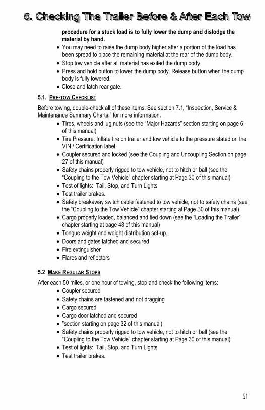
51
procedure for a stuck load is to fully lower the dump and dislodge the material by hand.
You may need to raise the dump body higher after a portion of the load has been spread to place the remaining material at the rear of the dump body.
Stop tow vehicle after all material has exited the dump body.
Press and hold button to lower the dump body. Release button when the dump body is fully lowered.
Close and latch rear gate.
5.1. PRE-TOW CHECKLIST
Before towing, double-check all of these items: See section 7.1, “Inspection, Service & Maintenance Summary Charts,” for more information.
Tires, wheels and lug nuts (see the “Major Hazards” section starting on page 6 of this manual)
Tire Pressure. Inflate tire on trailer and tow vehicle to the pressure stated on the VIN / Certification label.
Coupler secured and locked (see the Coupling and Uncoupling Section on page 27 of this manual)
Safety chains properly rigged to tow vehicle, not to hitch or ball (see the “Coupling to the Tow Vehicle” chapter starting at Page 30 of this manual)
Test of lights: Tail, Stop, and Turn Lights
Test trailer brakes.
Safety breakaway switch cable fastened to tow vehicle, not to safety chains (see the “Coupling to the Tow Vehicle” chapter starting at Page 30 of this manual)
Cargo properly loaded, balanced and tied down (see the “Loading the Trailer” chapter starting at page 48 of this manual)
Tongue weight and weight distribution set-up.
Doors and gates latched and secured
Fire extinguisher
Flares and reflectors 5.2 MAKE REGULAR STOPS
After each 50 miles, or one hour of towing, stop and check the following items:
Coupler secured
Safety chains are fastened and not dragging
Cargo secured
Cargo door latched and secured
”section starting on page 32 of this manual)
Safety chains properly rigged to tow vehicle, not to hitch or ball (see the “Coupling to the Tow Vehicle” chapter starting at Page 30 of this manual)
Test of lights: Tail, Stop, and Turn Lights
Test trailer brakes.
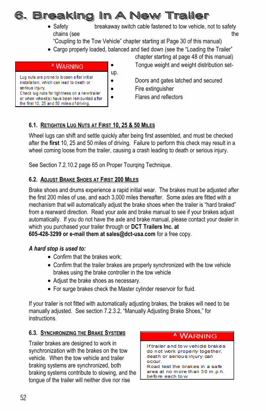
52
Safety breakaway switch cable fastened to tow vehicle, not to safety chains (see the “Coupling to the Tow Vehicle” chapter starting at Page 30 of this manual)
Cargo properly loaded, balanced and tied down (see the “Loading the Trailer” chapter starting at page 48 of this manual)
Tongue weight and weight distribution set-up.
Doors and gates latched and secured
Fire extinguisher
Flares and reflectors
6.1. RETIGHTEN LUG NUTS AT FIRST 10, 25 & 50 MILES
Wheel lugs can shift and settle quickly after being first assembled, and must be checked after the first 10, 25 and 50 miles of driving. Failure to perform this check may result in a wheel coming loose from the trailer, causing a crash leading to death or serious injury. See Section 7.2.10.2 page 65 on Proper Tourqing Technique. 6.2. ADJUST BRAKE SHOES AT FIRST 200 MILES
Brake shoes and drums experience a rapid initial wear. The brakes must be adjusted after the first 200 miles of use, and each 3,000 miles thereafter. Some axles are fitted with a mechanism that will automatically adjust the brake shoes when the trailer is “hard braked” from a rearward direction. Read your axle and brake manual to see if your brakes adjust automatically. If you do not have the axle and brake manual, please contact your dealer in which you purchased your trailer through or DCT Trailers Inc. at 605-428-3299 or e-mail them at [email protected] for a free copy. A hard stop is used to:
Confirm that the brakes work;
Confirm that the trailer brakes are properly synchronized with the tow vehicle brakes using the brake controller in the tow vehicle
Adjust the brake shoes as necessary.
For surge brakes check the Master cylinder reservoir for fluid. If your trailer is not fitted with automatically adjusting brakes, the brakes will need to be manually adjusted. See section 7.2.3.2, “Manually Adjusting Brake Shoes,” for instructions. 6.3. SYNCHRONIZING THE BRAKE SYSTEMS
Trailer brakes are designed to work in synchronization with the brakes on the tow vehicle. When the tow vehicle and trailer braking systems are synchronized, both braking systems contribute to slowing, and the tongue of the trailer will neither dive nor rise
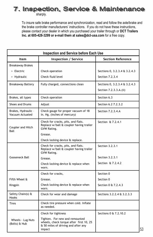
53
sharply. To insure safe brake performance and synchronization, read and follow the axle/brake and the brake controller manufacturers’ instructions. If you do not have these instructions, please contact your dealer in which you purchased your trailer through or DCT Trailers Inc. at 605-428-3299 or e-mail them at [email protected] for a free copy.
Inspection and Service before Each Use
Item Inspection / Service Section Reference
Breakaway Brakes
> Electric
> Hydraulic
Check operation
Check fluid level
Sections 0, 3.2.3.4 & 3.2.4.3
Section 7.2.3.4
Breakaway Battery Fully charged, connections clean Sections 0, 3.2.3.4 & 3.2.4.3
Section 7.2.3.3.A.(ii)
Brakes, all types Check operation Section 6.3
Shoes and Drums Adjust Section 6.2 7.2.3.2
Brakes, Hydraulic –
Vacuum Actuated
Check gauge for proper vacuum of 18
In. Hg. (inches of mercury) Section 7.2.3.4.A
Coupler and Hitch
Ball
Check for cracks, pits, and flats. Replace w/ball & coupler having trailer
GVW Rating.
Grease.
Check locking device & replace.
Section & 7.2.4.1
Gooseneck Ball
Check for cracks, pits, and flats. Replace w/ball & coupler having trailer
GVW Rating.
Grease.
Check locking device & replace when
worn.
Section 3.2.3.1
Section 3.2.3.1
Section & 7.2.4.2
Fifth Wheel &
Kingpin
Check for cracks,
Grease.
Check locking device & replace when
worn.
Section 0
Section 0
Section 0 & 7.2.4.3
Safety Chain(s) &
Hooks Check for wear and damage Sections 3.2.2.4 & 3.2.3.3
Tires Check tire pressure when cold. Inflate
as needed.
Wheels - Lug Nuts
(Bolts) & Hub
Check for tightness
Tighten. For new and remounted wheels, check torque after first 10, 25 & 50 miles of driving and after any
impact
Sections 0 & 7.2.10.2
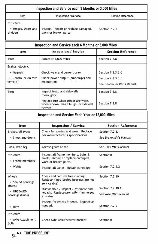
54
6.4. TIRE PRESSURE
Inspection and Service each 3 Months or 3,000 Miles
Item Inspection / Service Section Reference
Structure
> Hinges, Doors and
dividers
Inspect. Repair or replace damaged,
worn or broken parts
Section 7.2.2.
Inspection and Service each 6 Months or 6,000 Miles
Item Inspection / Service Section Reference
Tires Rotate @ 5,000 miles Section 7.2.8
Brakes, electric
> Magnets
> Controller (in tow
vehicle)
Check wear and current draw
Check power output (amperage) and
modulation
Section 7.2.3.3.C
Section 7.2.3.3.B
See Controller Mfr’s Manual
Tires Inspect tread and sidewalls
thoroughly.
Replace tire when treads are worn, when sidewall has a bulge, or sidewall
is worn
Section 7.2.8
Section 7.2.8
Inspection and Service Each Year or 12,000 Miles
Item Inspection / Service Section Reference
Brakes, all types
> Shoes and drums
Check for scoring and wear. Replace
per manufacturer’s specifications Section 7.2.3.1
See Brake Mfr’s Manual
Jack, Drop-leg Grease gears at top See Jack Mfr’s Manual
Structure
> Frame members
> Welds
Inspect all frame members, bolts & rivets. Repair or replace damaged,
worn or broken parts.
Inspect all welds. Repair as needed
Section 0
Section 7.2.2.2
Wheels
> Sealed Bearings
(Hubs)
> UNSEALED
Bearings (Hubs)
> Rims
Check and confirm free running. Replace if not (sealed bearings are not
serviceable)
Disassemble / inspect / assemble and repack. Replace promptly if immersed
in water
Inspect for cracks & dents. Replace as
needed.
Section 7.2.10
Section 7.2.10.1
See Axle Mfr’s Manual
Section 7.2.9
Structure
> Axle Attachment
Bolts
Check Axle Manufacturer booklet
Section 0
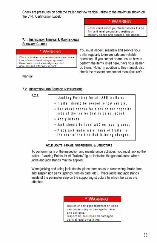
55
Check tire pressures on both the trailer and tow vehicle. Inflate to the maximum shown on the VIN / Certification Label.
7.1. INSPECTION SERVICE & MAINTENANCE SUMMARY CHARTS
You must inspect, maintain and service your trailer regularly to insure safe and reliable operation. If you cannot or are unsure how to perform the items listed here, have your dealer do them. Note: In addition to this manual, also check the relevant component manufacturer's
manual. 7.2. INSPECTION AND SERVICE INSTRUCTIONS
7.2.1.
AXLE BOLTS, FRAME, SUSPENSION, & STRUCTURE
To perform many of the inspection and maintenance activities, you must jack up the trailer. “Jacking Points for All Trailers” figure indicates the general areas where jacks and jack stands may be applied. When jacking and using jack stands, place them so as to clear wiring, brake lines, and suspension parts (springs, torsion bars, etc.). Place jacks and jack stands inside of the perimeter strip on the supporting structure to which the axles are attached.
J a c k i n g P o i n t ( s ) f o r a l l A B U t r a i l e r s :
T r a i l e r s h o u l d b e h o o k e d t o t o w v e h i c l e .
U s e w h e e l c h o c k s f o r t i r e s o n t h e o p p o s i t e s i d e o f t h e t r a i l e r t h a t i s b e i n g j a c k e d .
A p p l y b r a k e s .
J a c k s h o u l d b e l e v e l A N D o n l e v e l g r o u n d .
P l a c e j a c k u n d e r m a i n f r a m e o f t r a i l e r t o
t h e r e a r o f t h e t i r e t h a t i s b e i n g c h a n g e d .
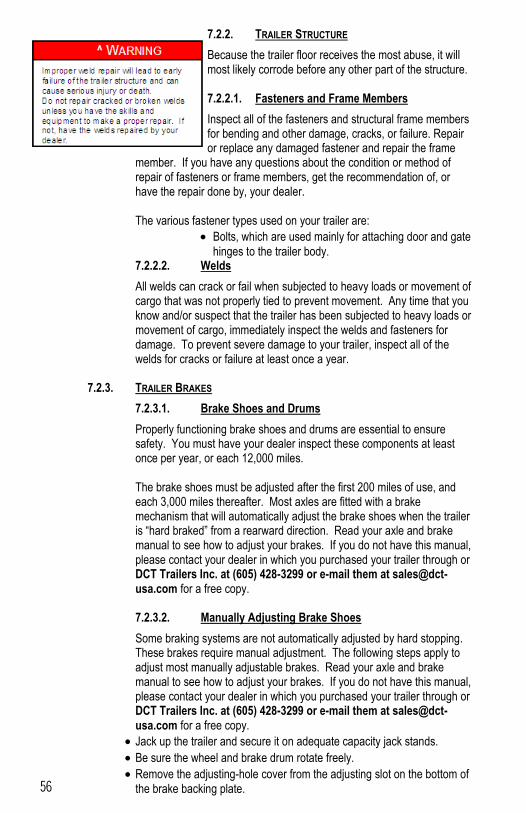
56
7.2.2. TRAILER STRUCTURE
Because the trailer floor receives the most abuse, it will most likely corrode before any other part of the structure. 7.2.2.1. Fasteners and Frame Members
Inspect all of the fasteners and structural frame members for bending and other damage, cracks, or failure. Repair or replace any damaged fastener and repair the frame
member. If you have any questions about the condition or method of repair of fasteners or frame members, get the recommendation of, or have the repair done by, your dealer. The various fastener types used on your trailer are:
Bolts, which are used mainly for attaching door and gate
hinges to the trailer body. 7.2.2.2. Welds
All welds can crack or fail when subjected to heavy loads or movement of cargo that was not properly tied to prevent movement. Any time that you know and/or suspect that the trailer has been subjected to heavy loads or movement of cargo, immediately inspect the welds and fasteners for damage. To prevent severe damage to your trailer, inspect all of the welds for cracks or failure at least once a year.
7.2.3. TRAILER BRAKES
7.2.3.1. Brake Shoes and Drums
Properly functioning brake shoes and drums are essential to ensure safety. You must have your dealer inspect these components at least once per year, or each 12,000 miles. The brake shoes must be adjusted after the first 200 miles of use, and each 3,000 miles thereafter. Most axles are fitted with a brake mechanism that will automatically adjust the brake shoes when the trailer is “hard braked” from a rearward direction. Read your axle and brake manual to see how to adjust your brakes. If you do not have this manual, please contact your dealer in which you purchased your trailer through or DCT Trailers Inc. at (605) 428-3299 or e-mail them at [email protected] for a free copy. 7.2.3.2. Manually Adjusting Brake Shoes
Some braking systems are not automatically adjusted by hard stopping. These brakes require manual adjustment. The following steps apply to adjust most manually adjustable brakes. Read your axle and brake manual to see how to adjust your brakes. If you do not have this manual, please contact your dealer in which you purchased your trailer through or DCT Trailers Inc. at (605) 428-3299 or e-mail them at [email protected] for a free copy.
Jack up the trailer and secure it on adequate capacity jack stands.
Be sure the wheel and brake drum rotate freely.
Remove the adjusting-hole cover from the adjusting slot on the bottom of the brake backing plate.
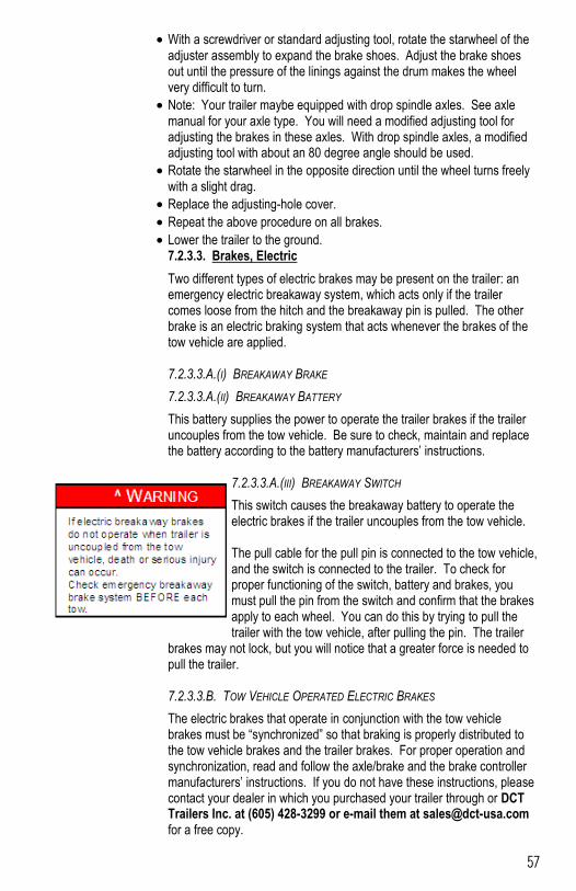
57
With a screwdriver or standard adjusting tool, rotate the starwheel of the adjuster assembly to expand the brake shoes. Adjust the brake shoes out until the pressure of the linings against the drum makes the wheel very difficult to turn.
Note: Your trailer maybe equipped with drop spindle axles. See axle manual for your axle type. You will need a modified adjusting tool for adjusting the brakes in these axles. With drop spindle axles, a modified adjusting tool with about an 80 degree angle should be used.
Rotate the starwheel in the opposite direction until the wheel turns freely with a slight drag.
Replace the adjusting-hole cover.
Repeat the above procedure on all brakes.
Lower the trailer to the ground. 7.2.3.3. Brakes, Electric
Two different types of electric brakes may be present on the trailer: an emergency electric breakaway system, which acts only if the trailer comes loose from the hitch and the breakaway pin is pulled. The other brake is an electric braking system that acts whenever the brakes of the tow vehicle are applied. 7.2.3.3.A.(I) BREAKAWAY BRAKE
7.2.3.3.A.(II) BREAKAWAY BATTERY
This battery supplies the power to operate the trailer brakes if the trailer uncouples from the tow vehicle. Be sure to check, maintain and replace the battery according to the battery manufacturers’ instructions.
7.2.3.3.A.(III) BREAKAWAY SWITCH
This switch causes the breakaway battery to operate the electric brakes if the trailer uncouples from the tow vehicle. The pull cable for the pull pin is connected to the tow vehicle, and the switch is connected to the trailer. To check for proper functioning of the switch, battery and brakes, you must pull the pin from the switch and confirm that the brakes apply to each wheel. You can do this by trying to pull the trailer with the tow vehicle, after pulling the pin. The trailer
brakes may not lock, but you will notice that a greater force is needed to pull the trailer. 7.2.3.3.B. TOW VEHICLE OPERATED ELECTRIC BRAKES
The electric brakes that operate in conjunction with the tow vehicle brakes must be “synchronized” so that braking is properly distributed to the tow vehicle brakes and the trailer brakes. For proper operation and synchronization, read and follow the axle/brake and the brake controller manufacturers’ instructions. If you do not have these instructions, please contact your dealer in which you purchased your trailer through or DCT Trailers Inc. at (605) 428-3299 or e-mail them at [email protected] for a free copy.
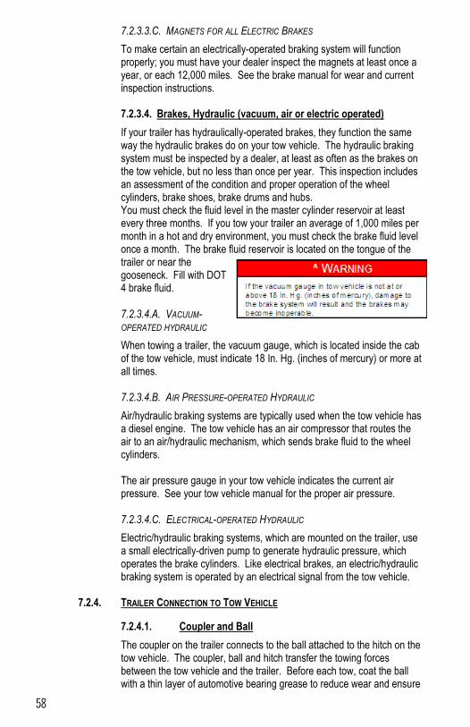
58
7.2.3.3.C. MAGNETS FOR ALL ELECTRIC BRAKES
To make certain an electrically-operated braking system will function properly; you must have your dealer inspect the magnets at least once a year, or each 12,000 miles. See the brake manual for wear and current inspection instructions. 7.2.3.4. Brakes, Hydraulic (vacuum, air or electric operated)
If your trailer has hydraulically-operated brakes, they function the same way the hydraulic brakes do on your tow vehicle. The hydraulic braking system must be inspected by a dealer, at least as often as the brakes on the tow vehicle, but no less than once per year. This inspection includes an assessment of the condition and proper operation of the wheel cylinders, brake shoes, brake drums and hubs. You must check the fluid level in the master cylinder reservoir at least every three months. If you tow your trailer an average of 1,000 miles per month in a hot and dry environment, you must check the brake fluid level once a month. The brake fluid reservoir is located on the tongue of the trailer or near the gooseneck. Fill with DOT 4 brake fluid. 7.2.3.4.A. VACUUM-OPERATED HYDRAULIC
When towing a trailer, the vacuum gauge, which is located inside the cab of the tow vehicle, must indicate 18 In. Hg. (inches of mercury) or more at all times. 7.2.3.4.B. AIR PRESSURE-OPERATED HYDRAULIC
Air/hydraulic braking systems are typically used when the tow vehicle has a diesel engine. The tow vehicle has an air compressor that routes the air to an air/hydraulic mechanism, which sends brake fluid to the wheel cylinders. The air pressure gauge in your tow vehicle indicates the current air pressure. See your tow vehicle manual for the proper air pressure. 7.2.3.4.C. ELECTRICAL-OPERATED HYDRAULIC
Electric/hydraulic braking systems, which are mounted on the trailer, use a small electrically-driven pump to generate hydraulic pressure, which operates the brake cylinders. Like electrical brakes, an electric/hydraulic braking system is operated by an electrical signal from the tow vehicle.
7.2.4. TRAILER CONNECTION TO TOW VEHICLE
7.2.4.1. Coupler and Ball
The coupler on the trailer connects to the ball attached to the hitch on the tow vehicle. The coupler, ball and hitch transfer the towing forces between the tow vehicle and the trailer. Before each tow, coat the ball with a thin layer of automotive bearing grease to reduce wear and ensure
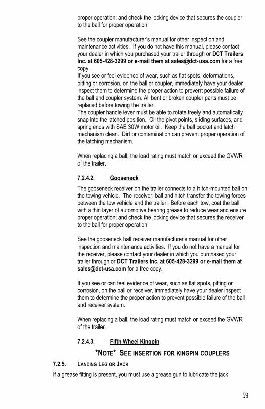
59
proper operation; and check the locking device that secures the coupler to the ball for proper operation. See the coupler manufacturer’s manual for other inspection and maintenance activities. If you do not have this manual, please contact your dealer in which you purchased your trailer through or DCT Trailers Inc. at 605-428-3299 or e-mail them at [email protected] for a free copy. If you see or feel evidence of wear, such as flat spots, deformations, pitting or corrosion, on the ball or coupler, immediately have your dealer inspect them to determine the proper action to prevent possible failure of the ball and coupler system. All bent or broken coupler parts must be replaced before towing the trailer. The coupler handle lever must be able to rotate freely and automatically snap into the latched position. Oil the pivot points, sliding surfaces, and spring ends with SAE 30W motor oil. Keep the ball pocket and latch mechanism clean. Dirt or contamination can prevent proper operation of the latching mechanism. When replacing a ball, the load rating must match or exceed the GVWR of the trailer. 7.2.4.2. Gooseneck
The gooseneck receiver on the trailer connects to a hitch-mounted ball on the towing vehicle. The receiver, ball and hitch transfer the towing forces between the tow vehicle and the trailer. Before each tow, coat the ball with a thin layer of automotive bearing grease to reduce wear and ensure proper operation; and check the locking device that secures the receiver to the ball for proper operation. See the gooseneck ball receiver manufacturer’s manual for other inspection and maintenance activities. If you do not have a manual for the receiver, please contact your dealer in which you purchased your trailer through or DCT Trailers Inc. at 605-428-3299 or e-mail them at [email protected] for a free copy. If you see or can feel evidence of wear, such as flat spots, pitting or corrosion, on the ball or receiver, immediately have your dealer inspect them to determine the proper action to prevent possible failure of the ball and receiver system. When replacing a ball, the load rating must match or exceed the GVWR of the trailer. 7.2.4.3. Fifth Wheel Kingpin
*NOTE* SEE INSERTION FOR KINGPIN COUPLERS
7.2.5. LANDING LEG OR JACK
If a grease fitting is present, you must use a grease gun to lubricate the jack
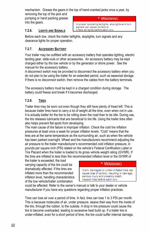
60
mechanism. Grease the gears in the top of hand-cranked jacks once a year, by removing the top of the jack and pumping or hand packing grease into the gears. 7.2.6. LIGHTS AND SIGNALS
Before each tow, check the trailer taillights, stoplights, turn signals and any clearance lights for proper operation. 7.2.7. ACCESSORY BATTERY
Your trailer may be outfitted with an accessory battery that operates lighting, electric landing gear, slide-outs or other accessories. An accessory battery may be kept charged either by the tow vehicle or by the generator or shore power. See the manual for the accessory battery. A disconnect switch may be provided to disconnect the accessory battery when you do not plan to be using the trailer for an extended period, such as seasonal storage. If there is no disconnect switch, then remove the cables from the battery terminals. The accessory battery must be kept in a charged condition during storage. The battery could freeze and break if it becomes discharged. 7.2.8. TIRES
Trailer tires may be worn out even though they still have plenty of tread left. This is because trailer tires have to carry a lot of weight all the time, even when not in use. It is actually better for the tire to be rolling down the road than to be idle. During use, the tire releases lubricants that are beneficial to tire life. Using the trailer tires often also helps prevent flat spots from developing. The main cause of tire failure is improper inflation. Check the cold tire inflation pressures at least once a week for proper inflation levels. “Cold” means that the tires are at the same temperature as the surrounding air, such as when the vehicle has been parked overnight. Wheel and tire manufacturers recommend adjusting the air pressure to the trailer manufacturer’s recommended cold inflation pressure, in pounds per square inch (PSI) stated on the vehicle’s Federal Certification Label or Tire Placard when the trailer is loaded to its gross vehicle weight rating (GVWR). If the tires are inflated to less than the recommended inflation level or the GVWR of the trailer is exceeded, the load carrying capacity of the tire could be dramatically affected. If the tires are inflated more than the recommended inflation level, handling characteristics of the tow vehicle/trailer combination could be affected. Refer to the owner’s manual or talk to your dealer or vehicle manufacturer if you have any questions regarding proper inflation practices. Tires can lose air over a period of time. In fact, tires can lose 1 to 3 PSI per month. This is because molecules of air, under pressure, weave their way from the inside of the tire, through the rubber, to the outside. A drop in tire pressure could cause the tire to become overloaded, leading to excessive heat build up. If a trailer tire is under-inflated, even for a short period of time, the tire could suffer internal damage.
61
High speed towing in hot conditions degrades trailer tires significantly. As heat builds up during driving, the tire’s internal structure starts to breakdown, compromising the strength of the tire. It is recommended to drive at moderate speeds. Statistics indicate the average life of a trailer tire is about five years under normal use and maintenance conditions. After three years, replacing the trailer tires with new ones should be considered, even if the tires have adequate tread depth. Some expert’s claim that after five years, trailer tires are considered worn out and should be replaced, even if they have had minimal or no use. This is such a general statement that it may not apply in all cases. It is best to have your tires inspected by a tire supplier to determine if your tires need to be replaced. If you are storing your trailer for an extended period, make sure the tires are fully inflated to the maximum rated pressure and that you store them in a cool, dry place, such as a garage. Use tire covers to protect the trailer tires from the harsh effects of the sun. 7.2.9. WHEEL RIMS
If the trailer has been struck, or impacted, on or near the wheels, or if the trailer has struck a curb, inspect the rims for damage (i.e. being out of round); and replace any damaged wheel. Inspect the wheels for damage every year, even if no obvious impact has occurred. 7.2.10. WHEELS, BEARINGS AND LUG NUTS
A loose, worn or damaged wheel bearing is the most common cause of brakes that grab. To check your bearings, jack trailer and check wheels for side-to-side looseness. If the wheels are loose, or spin with a wobble, the bearings must be serviced or replaced. Most trailer axles are built with
sealed bearings that are not serviceable. Sealed bearings must be replaced as complete units.
7.2.10.1. Unsealed Bearings (Hubs)
If your trailer has unsealed axle bearings, they must be inspected and lubricated once a year or 12,000 miles to insure safe operation of your trailer. If a trailer wheel bearing is immersed in water, it must be replaced.
If your trailer has not been used for an extended amount of time, have the
T o v i e w a n e x p l o d e d p i c t u r e o f a w h e e l b e a r i n g , p l e a s e s e e t h e A x l e O w n e r ’ s M a n u a l t h a t h a s a l s o b e e n s e n t a l o n g w i t h y o u r A B U T r a i l e r s I n c . U s e r ’ s M a n u a l i n t h e p a c k e t y o u r e c e i v e d f r o m t h e A B U d e a l e r i n w h i c h y o u p u r c h a s e d t h e t r a i l e r f r o m .
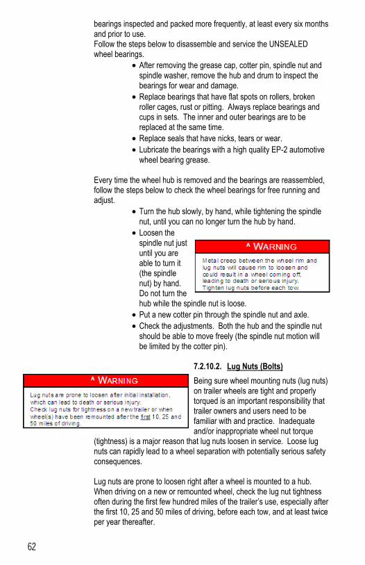
62
bearings inspected and packed more frequently, at least every six months and prior to use. Follow the steps below to disassemble and service the UNSEALED wheel bearings.
After removing the grease cap, cotter pin, spindle nut and spindle washer, remove the hub and drum to inspect the bearings for wear and damage.
Replace bearings that have flat spots on rollers, broken roller cages, rust or pitting. Always replace bearings and cups in sets. The inner and outer bearings are to be replaced at the same time.
Replace seals that have nicks, tears or wear.
Lubricate the bearings with a high quality EP-2 automotive wheel bearing grease.
Every time the wheel hub is removed and the bearings are reassembled, follow the steps below to check the wheel bearings for free running and adjust.
Turn the hub slowly, by hand, while tightening the spindle nut, until you can no longer turn the hub by hand.
Loosen the spindle nut just until you are able to turn it (the spindle nut) by hand. Do not turn the hub while the spindle nut is loose.
Put a new cotter pin through the spindle nut and axle.
Check the adjustments. Both the hub and the spindle nut should be able to move freely (the spindle nut motion will be limited by the cotter pin).
7.2.10.2. Lug Nuts (Bolts)
Being sure wheel mounting nuts (lug nuts) on trailer wheels are tight and properly torqued is an important responsibility that trailer owners and users need to be familiar with and practice. Inadequate and/or inappropriate wheel nut torque
(tightness) is a major reason that lug nuts loosen in service. Loose lug nuts can rapidly lead to a wheel separation with potentially serious safety consequences. Lug nuts are prone to loosen right after a wheel is mounted to a hub. When driving on a new or remounted wheel, check the lug nut tightness often during the first few hundred miles of the trailer’s use, especially after the first 10, 25 and 50 miles of driving, before each tow, and at least twice per year thereafter.
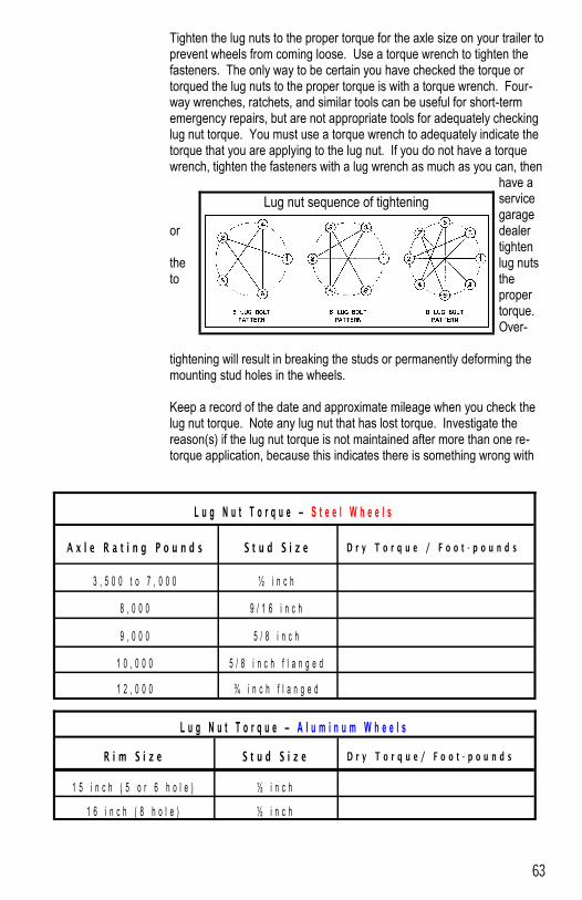
63
Tighten the lug nuts to the proper torque for the axle size on your trailer to prevent wheels from coming loose. Use a torque wrench to tighten the fasteners. The only way to be certain you have checked the torque or torqued the lug nuts to the proper torque is with a torque wrench. Four-way wrenches, ratchets, and similar tools can be useful for short-term emergency repairs, but are not appropriate tools for adequately checking lug nut torque. You must use a torque wrench to adequately indicate the torque that you are applying to the lug nut. If you do not have a torque wrench, tighten the fasteners with a lug wrench as much as you can, then
have a service garage
or dealer tighten
the lug nuts to the
proper torque. Over-
tightening will result in breaking the studs or permanently deforming the mounting stud holes in the wheels. Keep a record of the date and approximate mileage when you check the lug nut torque. Note any lug nut that has lost torque. Investigate the reason(s) if the lug nut torque is not maintained after more than one re-torque application, because this indicates there is something wrong with
Lug nut sequence of tightening
L u g N u t T o r q u e – A l u m i n u m W h e e l s
R i m S i z e S t u d S i z e D r y T o r q u e / F o o t - p o u n d s
1 5 i n c h ( 5 o r 6 h o l e ) ½ i n c h
1 6 i n c h ( 8 h o l e ) ½ i n c h
L u g N u t T o r q u e – S t e e l W h e e l s
A x l e R a t i n g P o u n d s S t u d S i z e D r y T o r q u e / F o o t - p o u n d s
3 , 5 0 0 t o 7 , 0 0 0 ½ i n c h
8 , 0 0 0 9 / 1 6 i n c h
9 , 0 0 0 5 / 8 i n c h
1 0 , 0 0 0 5 / 8 i n c h f l a n g e d
1 2 , 0 0 0 ¾ i n c h f l a n g e d
64
the lug nuts, nut studs, wheels and/or hubs and should be corrected.
Contact your dealer or vehicle manufacturer immediately if you experience any persistent lug nut loosening or any other lug, wheel or axle problems. In the event of a wheel separation incident, notify the vehicle manufacturer and dealer. Seek prompt professional assistance in assessing the trailer and its gear, and retain, but don’t re-use involved lugs, wheels and studs. Don’t repair or service the trailer yourself. Call a trained technician. Dry Torque Foot-pounds is determined by manufacturer.
DCT Trailers, warrants that each trailer operated by the original purchaser under normal use, will be free from defects in material and workmanship for a person of one (1) year from date of purchase, provide the trailer is not rented or used for commercial hauling, in which case this warranty is null and void.
Subject to the requirements, exclusions and limitations stated below, DCT Trailers, will correct any defects in material and workmanship which DCT Trailers is informed of within the one year period.
1. Original Purchaser: This warranty is extended to the original retail purchaser only, and is terminated upon sale, assignment, or transfer of the trailer by the original purchaser.
2. Warranty Registration Card: To validate this Warranty, the Warranty Registration Card included in your owner’s packet, provided by your dealer must be signed and returned to DCT Trailers within ten (10) days of the date of purchase. merchantability and fitness for intended use a re limited to warranty period stated above; unless any state
3. Specific Exclusions: This Warranty specifically excludes the following parts and equipment of DCT Trailers. A. Tires and tubes are warranted by their manufacturer. B. Axles, brakes and brake components are warranted by their manufacturer. C. Trailer hitch, hitch components, jacks and casters are warranted by their manufacturer.
4. Normal Use: This Warranty covers only defects in original components which arise from normal use and does not apply if the trailer has been subjected to negligence, accident, abuse, alteration or overloaded or has been repaired without prior authorization from DCT Trailers.
5. Prior Consent: Any repairs made other than at DCT Trailers, must be authorized by DCT Trailers. No reimbursement will be made to any dealer or owner for repairs without the prior consent of DCT Trailers.
6. Required Procedure: In order to speed the correction of any problem covered by this Warranty, the following procedure must be followed.
47138 246th St. Dell Rapids, SD 57022 Phone: 605-428-3299 ~ Fax: 605-428-5681
65
A. To validate the Warranty, you must sign and return the Warranty Registration Card in your owner’s packet to DCT Trailers within ten (10) days of the date of purchase of your trailer.
MAINTENANCE RECORD
DATE MILES SERVICE PERFORMED
66
WARRANTY REPAIR RECORD
DATE MILES SERVICES PERFORMED SERVICED AT
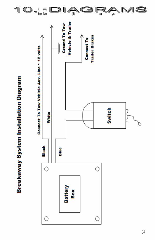
67
B. Within five (5) da ys
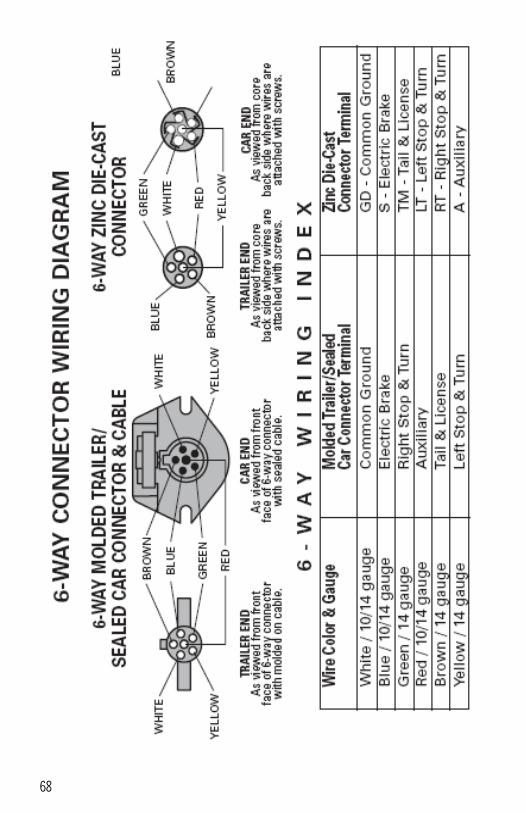
68
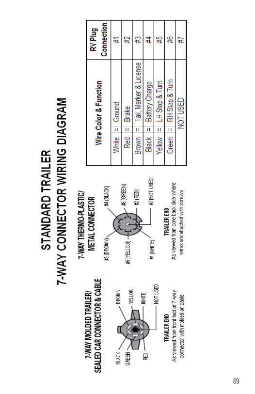
69
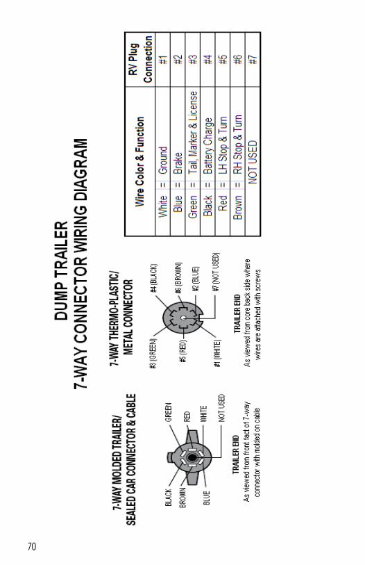
70
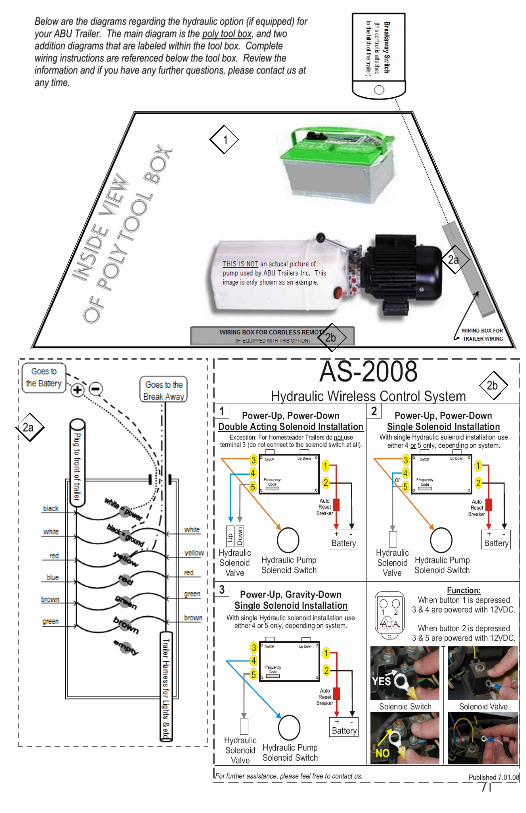
71
after discovering a problem, return your trailer to you dealer for inspection. Dealers are responsible for fixing minor problems without charge to you or the factory. This is you vest and fastest remedy for small problems.
C. If your local dealer cannot repair the problem, and you wish to make a claim under this Warranty, have your dealer notify DCT Trailers, 47138 246th St. Dell Rapids, SD 57022 of your claim.
1
2a
2b
Below are the diagrams regarding the hydraulic option (if equipped) for your ABU Trailer. The main diagram is the poly tool box, and two addition diagrams that are labeled within the tool box. Complete wiring instructions are referenced below the tool box. Review the information and if you have any further questions, please contact us at any time.
2a
2b
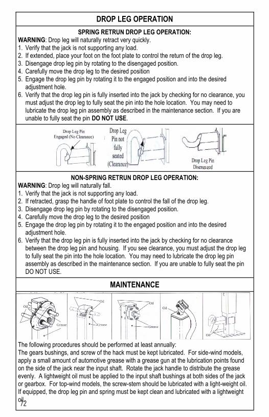
72
DROP LEG OPERATION
SPRING RETRUN DROP LEG OPERATION: WARNING: Drop leg will naturally retract very quickly. 1. Verify that the jack is not supporting any load. 2. If extended, place your foot on the foot plate to control the return of the drop leg. 3. Disengage drop leg pin by rotating to the disengaged position. 4. Carefully move the drop leg to the desired position 5. Engage the drop leg pin by rotating it to the engaged position and into the desired
adjustment hole. 6. Verify that the drop leg pin is fully inserted into the jack by checking for no clearance, you
must adjust the drop leg to fully seat the pin into the hole location. You may need to lubricate the drop leg pin assembly as described in the maintenance section. If you are unable to fully seat the pin DO NOT USE.
NON-SPRING RETRUN DROP LEG OPERATION: WARNING: Drop leg will naturally fall. 1. Verify that the jack is not supporting any load. 2. If retracted, grasp the handle of foot plate to control the fall of the drop leg. 3. Disengage drop leg pin by rotating to the disengaged position. 4. Carefully move the drop leg to the desired position 5. Engage the drop leg pin by rotating it to the engaged position and into the desired
adjustment hole. 6. Verify that the drop leg pin is fully inserted into the jack by checking for no clearance
between the drop leg pin and housing. If you see clearance, you must adjust the drop leg to fully seat the pin into the hole location. You may need to lubricate the drop leg pin assembly as described in the maintenance section. If you are unable to fully seat the pin DO NOT USE.
MAINTENANCE
The following procedures should be performed at least annually: The gears bushings, and screw of the hack must be kept lubricated. For side-wind models, apply a small amount of automotive grease with a grease gun at the lubrication points found on the side of the jack near the input shaft. Rotate the jack handle to distribute the grease evenly. A lightweight oil must be applied to the input shaft bushings at both sides of the jack or gearbox. For top-wind models, the screw-stem should be lubricated with a light-weight oil. If equipped, the drop leg pin and spring must be kept clean and lubricated with a lightweight oil.
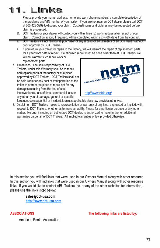
73
Please provide your name, address, home and work phone numbers, a complete description of the problems and VIN number of your trailer. If you are not near an DCT dealer please call DCT at 605-428-3299 to discuss your claim. Cost estimates and pictures may be requested before claim is processed.
D. DCT Trailers or your dealer will contact you within three (3) working days after receipt of your claim. Correction action, if required, will be completed within sixty (60) days from the contract.
E. DCT Trailers will not reimburse purchaser of any repairs or adjustments of an DCT trailer without prior approval by DCT Trailers.
F. If you return your trailer for repair to the factory, we will warrant the repair of replacement parts for a year from date of repair. If authorized repair must be done other than at DCT Trailers, we will not warrant such repair work or replacement parts.
7. Limitations: The sole responsibility of DCT Trailers, under this Warranty shall be to repair and replace parts at the factory or at a place approved by DCT Trailers. DCT Trailers shall not be held liable for any cost of transportation of the trailer to or from the place of repair not for any damages resulting from the lost of use, inconvenience, loss of time, commercial loss or any other type of damage, general or specific, foreseen, consequential or incidental, unless applicable state law provides otherwise.
8. Disclaimer: DCT Trailers makes to representation or warranty of any kind, expressed or implied, with respect to DCT Trailers, whether as to merchantability, fitness for a particular purpose or any other matter. No one, including an authorized DCT dealer, is authorized to make further or additional warranties on behalf of DCT Trailers. All implied warranties of law provided otherwise.
In this section you will find links that were used in our Owners Manual along with other resource In this section you will find links that were used in our Owners Manual along with other resource links. If you would like to contact ABU Trailers Inc. or any of the other websites for information, please use the links listed below:
[email protected] http://www.dct-usa.com
ASSOCIATIONS The following links are listed by:
American Rental Association
http//www.ntda.org/
74
http//www.ararental.org/ National Truck Equipment Association http//www.ntea.org/ National Wheel & Rim Association http//www.nationalwheelandrim.org/ Recreational Vehicle Industry Association http//www.rvia.com/ Society of Automotive Engineers http//www.sae.org/ Truck Trailer Manufacturers Association http//www.ttmanet.org/ STANDARDS & REGULATIONS
American National Standards Institute http//www.ansi.org/ Code of Federal Regulations http//www.access.gpo.gov/nara/cfr/cfr-table-search.html Federal Motor Vehicle Safety Standards http//www.access.gpo.gov/nara/cfr/waisidx_99/49cfr571_99.html Federal Register http//www.gpoaccess.gov/fr/ Trailer Lighting Posters http//www.nhtsa.dot.gov/cars/rules/standards/conspicuity/Trlrpstr.html EARLY WARNING REPORTING
NHTSA – Early Warning Reporting http//www-odi.nhtsa.dot.gov/ewr/ewr.cfm GOVERNMENT
Federal Highway Administration http//www.fhwa.dot.gov/ Federal Motor Carrier Safety Administration http//www.fmcsa.dot.gov/ Federal Register http//www.gpoaccess.gov/fr/ National Highway Traffic Safety Administration (NHTSA) http//www.nhtsa.dot.gov/cars/rules/ NHTSA Information for New Manufacturers

75
76
http//www.nhtsa.dot.gov/cars/rules/maninfo/ NHTSA Manufacturer Information http//www.nhtsa.dot.gov/cars/rules/manufacture/ Search Bill Summary & Status – 108th Congress http//thomas.loc.gov/bss/d108query.html State by State Lemon Law Information http//www.autopedia.com/html/HotLinks_Lemon2.html U.S. Department of Transportation (USDOT) http//www.dot.gov/ CANADA
Canadian Council of Motor Transport Administrators http//www.ccmta.ca/english/ Canadian Transportation Equipment Association http//www.ctea.on.ca/ Transport Canada http//www.tc.gc.ca/en/menu.htm
Dell Rapids Custom Trailers, Inc.
47138 246th St. Dell Rapids, SD 57022