dell networking mxl and m ioa fc-flexio direct connect...
TRANSCRIPT
A Dell Deployment Guide
Dell Networking MXL and M IOA FC-FlexIO Direct Connect Storage Deployment Guide A Dell Deployment Guide FC FlexIO Fabric Services Update - Providing F-port Connectivity to Storage
Dell Networking Solutions Engineering February 2015
2 Dell Networking MXL and M IOA FC-FlexIO Direct Connect Storage Deployment Guide | Version 1.0
Revisions
Date Description Authors
February 2015 Initial Release Jim Slaughter, Kevin Locklear, Curtis Bunch
©2015 Dell Inc., All rights reserved.
Except as stated below, no part of this document may be reproduced, distributed or transmitted in any form or by any
means, without express permission of Dell.
You may distribute this document within your company or organization only, without alteration of its contents.
THIS DOCUMENT IS PROVIDED “AS-IS”, AND WITHOUT ANY WARRANTY, EXPRESS OR IMPLIED. IMPLIED
WARRANTIES OF MERCHANTABILITY AND FITNESS FOR A PARTICULAR PURPOSE ARE SPECIFICALLY DISCLAIMED.
PRODUCT WARRANTIES APPLICABLE TO THE DELL PRODUCTS DESCRIBED IN THIS DOCUMENT MAY BE FOUND
AT: http://www.dell.com/learn/us/en/19/terms-of-sale-commercial-and-public-sector Performance of network
reference architectures discussed in this document may vary with differing deployment conditions, network loads, and
the like. Third party products may be included in reference architectures for the convenience of the reader. Inclusion
of such third party products does not necessarily constitute Dell’s recommendation of those products. Please consult
your Dell representative for additional information. This document is an independent publication and has not been
authorized, sponsored, or otherwise approved by NetApp, Inc., or VMware Inc.
Trademarks used in this text:
Dell™, the Dell logo, PowerEdge™, PowerVault™, PowerConnect™, OpenManage™, EqualLogic™, Compellent™,
KACE™, FlexAddress™, Force10™ and Vostro™ are trademarks of Dell Inc. Other Dell trademarks may be used in this
document. Cisco Nexus®, Cisco MDS®, Cisco NX-0S®, and other Cisco Catalyst® are registered trademarks of Cisco
System Inc. EMC VNX®, and EMC Unisphere® are registered trademarks of EMC Corporation. NetApp® and NetApp
FAS3200 series are trademarks/registered trademarks of NetApp, Inc. registered in the U.S. and/or other countries.
Emulex® and OneCommand™ are trademarks of Emulex Corporation. Intel®, Pentium®, Xeon®, Core® and
Celeron® are registered trademarks of Intel Corporation in the U.S. and other countries. Microsoft®, Windows®,
Windows Server®, Internet Explorer®, and Active Directory® are either trademarks or registered trademarks of
Microsoft Corporation in the United States and/or other countries. Red Hat® and Red Hat® Enterprise Linux® are
registered trademarks of Red Hat, Inc. in the United States and/or other countries. Novell® and SUSE® are registered
trademarks of Novell Inc. in the United States and other countries. Oracle® is a registered trademark of Oracle
Corporation and/or its affiliates. Citrix®, Xen®, XenServer® and XenMotion® are either registered trademarks or
trademarks of Citrix Systems, Inc. in the United States and/or other countries. VMware®, Virtual SMP®, vMotion®,
vCenter® and vSphere® are registered trademarks or trademarks of VMware, Inc. in the United States or other
countries. IBM® is a registered trademark of International Business Machines Corporation. Broadcom® and
NetXtreme® are registered trademarks of Broadcom Corporation. Qlogic is a registered trademark of QLogic
Corporation. Other trademarks and trade names may be used in this document to refer to either the entities claiming
the marks and/or names or their products and are the property of their respective owners. Dell disclaims proprietary
interest in the marks and names of others.
3 Dell Networking MXL and M IOA FC-FlexIO Direct Connect Storage Deployment Guide | Version 1.0
Table of contents Revisions .................................................................................................................................................................................................. 2
1 Introduction ..................................................................................................................................................................................... 5
1.1 Typographical Conventions .............................................................................................................................................. 7
2 Hardware ......................................................................................................................................................................................... 8
2.1 Dell PowerEdge M1000e .................................................................................................................................................. 8
2.2 M1000e I/O Modules ......................................................................................................................................................... 9
2.2.1 Dell MXL 10/40GbE Overview ......................................................................................................................................... 9
2.2.2 Dell M I/O Aggregator Overview ..................................................................................................................................... 9
2.2.3 FlexIO Expansion Modules ............................................................................................................................................... 9
2.3 Dell PowerEdge M620 Blade Server ............................................................................................................................ 10
2.4 Dell Networking S-Series S6000 Managed Switch .................................................................................................... 11
2.5 NetApp FAS3200 Series Data Storage System ............................................................................................................ 11
3 Converged Network Adapter Configuration .......................................................................................................................... 12
4 Storage Configuration ................................................................................................................................................................. 12
5 Switch Configurations ................................................................................................................................................................. 13
5.1 Ethernet Topology ............................................................................................................................................................ 13
5.2 Storage Topology .............................................................................................................................................................. 13
5.3 Switch Configurations ...................................................................................................................................................... 15
5.3.1 M I/O Aggregator ..............................................................................................................................................................16
5.3.2 Dell Networking MXL ........................................................................................................................................................19
5.3.3 Validation ............................................................................................................................................................................ 20
5.3.4 Optional Configuration: F-port Without Zoning ....................................................................................................... 25
6 Server Configuration ................................................................................................................................................................... 26
6.1 VMware ESXi 5.5 - Installation, Configuration and Validation ................................................................................ 26
6.2 Microsoft Server Operating System MPIO Installation and Configuration .......................................................... 29
7 Conclusion .................................................................................................................................................................................... 33
A Appendix ........................................................................................................................................................................................ 34
A.1 Configuration Details ....................................................................................................................................................... 34
A.2 PowerEdge M I/O Aggregator Operational Modes ................................................................................................... 35
A.3 PowerEdge M1000e Port Mapping .............................................................................................................................. 36
A.4 Fibre Channel over Ethernet and Data Center Bridging .......................................................................................... 38
4 Dell Networking MXL and M IOA FC-FlexIO Direct Connect Storage Deployment Guide | Version 1.0
Support and Feedback ....................................................................................................................................................................... 39
5 Dell Networking MXL and M IOA FC-FlexIO Direct Connect Storage Deployment Guide | Version 1.0
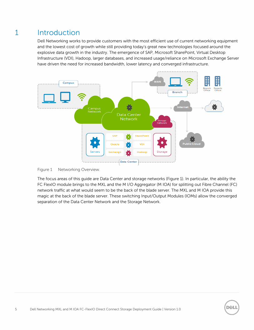
1 Introduction Dell Networking works to provide customers with the most efficient use of current networking equipment
and the lowest cost of growth while still providing today’s great new technologies focused around the
explosive data growth in the industry. The emergence of SAP, Microsoft SharePoint, Virtual Desktop
Infrastructure (VDI), Hadoop, larger databases, and increased usage/reliance on Microsoft Exchange Server
have driven the need for increased bandwidth, lower latency and converged infrastructure.
Figure 1 Networking Overview.
The focus areas of this guide are Data Center and storage networks (Figure 1). In particular, the ability the
FC FlexIO module brings to the MXL and the M I/O Aggregator (M IOA) for splitting out Fibre Channel (FC)
network traffic at what would seem to be the back of the blade server. The MXL and M IOA provide this
magic at the back of the blade server. These switching Input/Output Modules (IOMs) allow the converged
separation of the Data Center Network and the Storage Network.
6 Dell Networking MXL and M IOA FC-FlexIO Direct Connect Storage Deployment Guide | Version 1.0
Server Storage
MXL/IOA
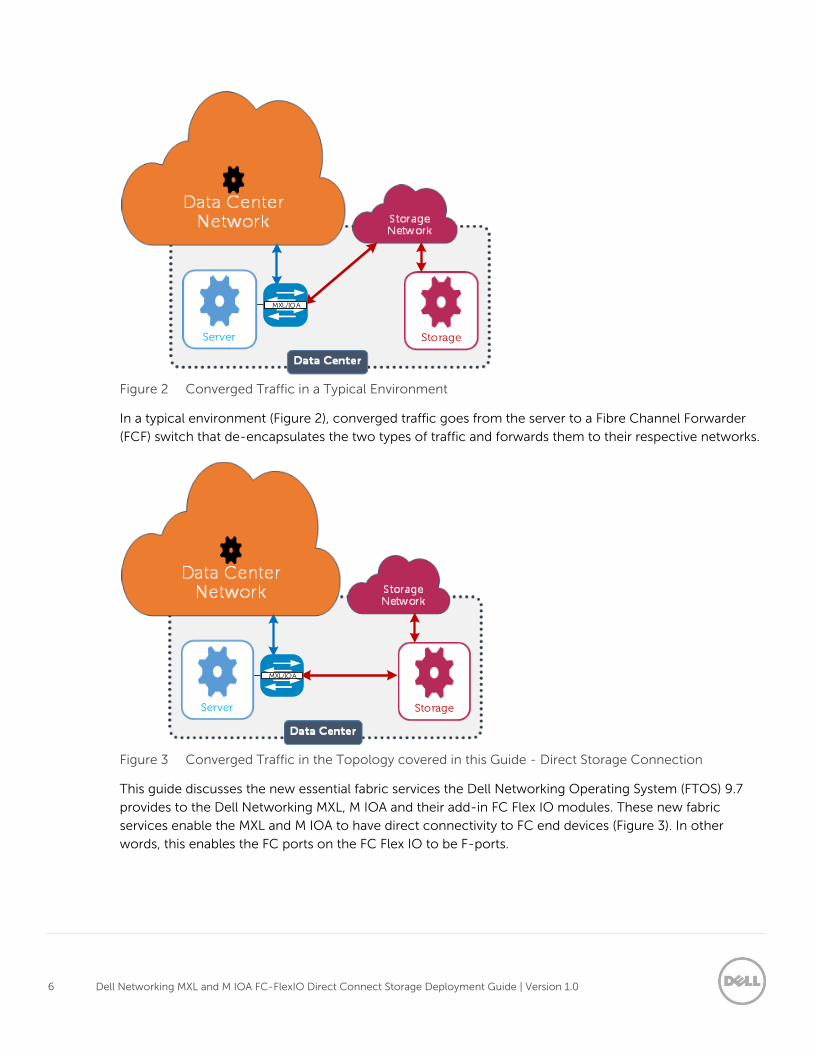
Figure 2 Converged Traffic in a Typical Environment
In a typical environment (Figure 2), converged traffic goes from the server to a Fibre Channel Forwarder
(FCF) switch that de-encapsulates the two types of traffic and forwards them to their respective networks.
Server Storage
MXL/IOA
Figure 3 Converged Traffic in the Topology covered in this Guide - Direct Storage Connection
This guide discusses the new essential fabric services the Dell Networking Operating System (FTOS) 9.7
provides to the Dell Networking MXL, M IOA and their add-in FC Flex IO modules. These new fabric
services enable the MXL and M IOA to have direct connectivity to FC end devices (Figure 3). In other
words, this enables the FC ports on the FC Flex IO to be F-ports.
7 Dell Networking MXL and M IOA FC-FlexIO Direct Connect Storage Deployment Guide | Version 1.0
1.1 Typographical Conventions Monospace Text CLI examples
Underlined Monospace Text CLI examples that word wrap. This text should be entered as a single
command.
Italic Monospace Text Variables in CLI examples
Bold monospace Text Commands entered at the CLI prompt
8 Dell Networking MXL and M IOA FC-FlexIO Direct Connect Storage Deployment Guide | Version 1.0
2 Hardware In this section, the hardware used to validate the topology outlined in this deployment guide is briefly
discussed.
Note: Refer to the Configuration Details section in the Appendix for specific firmware and driver versions.
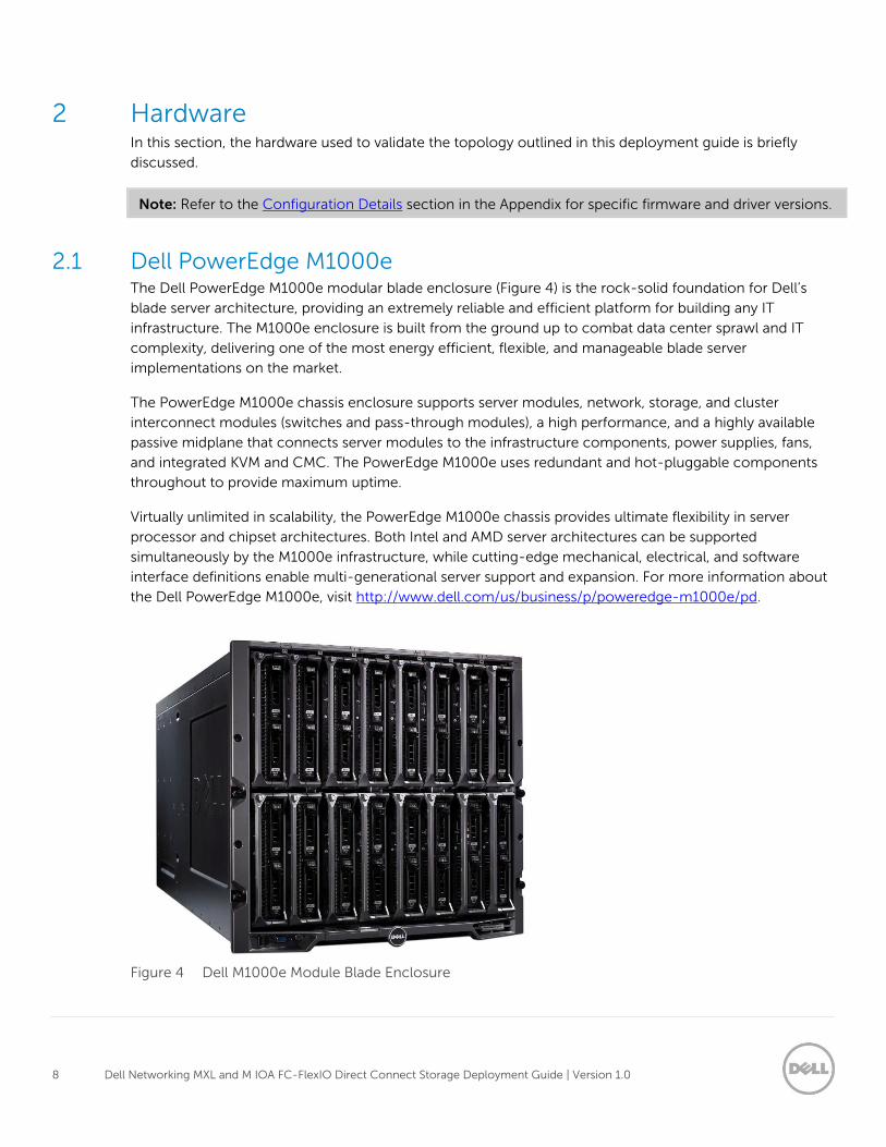
2.1 Dell PowerEdge M1000e The Dell PowerEdge M1000e modular blade enclosure (Figure 4) is the rock-solid foundation for Dell’s
blade server architecture, providing an extremely reliable and efficient platform for building any IT
infrastructure. The M1000e enclosure is built from the ground up to combat data center sprawl and IT
complexity, delivering one of the most energy efficient, flexible, and manageable blade server
implementations on the market.
The PowerEdge M1000e chassis enclosure supports server modules, network, storage, and cluster
interconnect modules (switches and pass-through modules), a high performance, and a highly available
passive midplane that connects server modules to the infrastructure components, power supplies, fans,
and integrated KVM and CMC. The PowerEdge M1000e uses redundant and hot-pluggable components
throughout to provide maximum uptime.
Virtually unlimited in scalability, the PowerEdge M1000e chassis provides ultimate flexibility in server
processor and chipset architectures. Both Intel and AMD server architectures can be supported
simultaneously by the M1000e infrastructure, while cutting-edge mechanical, electrical, and software
interface definitions enable multi-generational server support and expansion. For more information about
the Dell PowerEdge M1000e, visit http://www.dell.com/us/business/p/poweredge-m1000e/pd.
Figure 4 Dell M1000e Module Blade Enclosure
9 Dell Networking MXL and M IOA FC-FlexIO Direct Connect Storage Deployment Guide | Version 1.0
2.2 M1000e I/O Modules M1000e blade environments can be expanded quickly and easily with Dell’s complete, scale-on-demand
switch designs and IO modules that support three fully redundant fabrics. IO options include Dell
Networking switches with FlexIO technology that provide on-demand stacking and modular uplink
scalability.
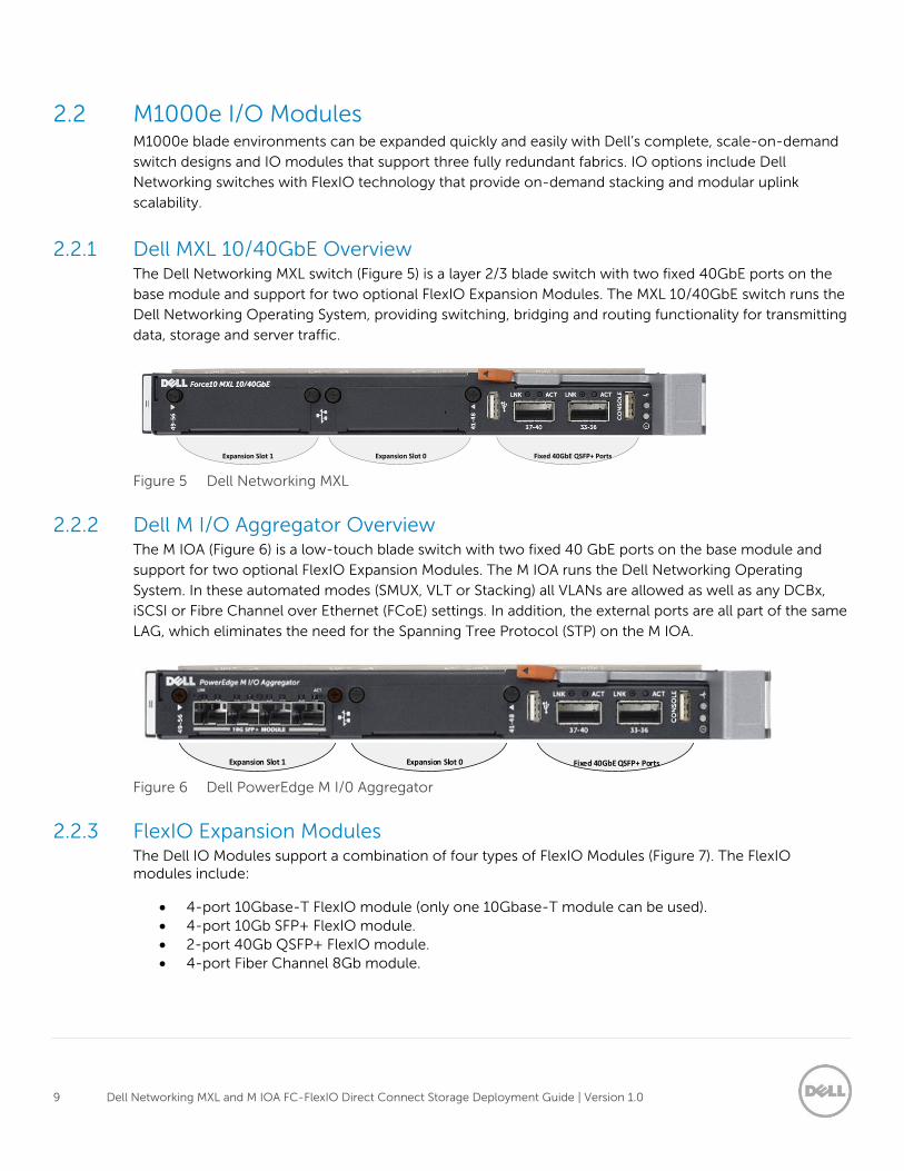
2.2.1 Dell MXL 10/40GbE Overview The Dell Networking MXL switch (Figure 5) is a layer 2/3 blade switch with two fixed 40GbE ports on the
base module and support for two optional FlexIO Expansion Modules. The MXL 10/40GbE switch runs the
Dell Networking Operating System, providing switching, bridging and routing functionality for transmitting
data, storage and server traffic.
Fixed 40GbE QSFP+ PortsExpansion Slot 0Expansion Slot 1
Figure 5 Dell Networking MXL
2.2.2 Dell M I/O Aggregator Overview The M IOA (Figure 6) is a low-touch blade switch with two fixed 40 GbE ports on the base module and
support for two optional FlexIO Expansion Modules. The M IOA runs the Dell Networking Operating
System. In these automated modes (SMUX, VLT or Stacking) all VLANs are allowed as well as any DCBx,
iSCSI or Fibre Channel over Ethernet (FCoE) settings. In addition, the external ports are all part of the same
LAG, which eliminates the need for the Spanning Tree Protocol (STP) on the M IOA.
I/O Bay 1
Expansion Slot 1 Expansion Slot 0 Fixed 40GbE QSFP+ Ports
Figure 6 Dell PowerEdge M I/0 Aggregator
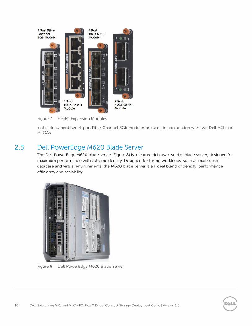
2.2.3 FlexIO Expansion Modules The Dell IO Modules support a combination of four types of FlexIO Modules (Figure 7). The FlexIO modules include:
4-port 10Gbase-T FlexIO module (only one 10Gbase-T module can be used).
4-port 10Gb SFP+ FlexIO module.
2-port 40Gb QSFP+ FlexIO module.
4-port Fiber Channel 8Gb module.
10 Dell Networking MXL and M IOA FC-FlexIO Direct Connect Storage Deployment Guide | Version 1.0
Figure 7 FlexIO Expansion Modules
In this document two 4-port Fiber Channel 8Gb modules are used in conjunction with two Dell MXLs or M IOAs.
2.3 Dell PowerEdge M620 Blade Server The Dell PowerEdge M620 blade server (Figure 8) is a feature rich, two-socket blade server, designed for
maximum performance with extreme density. Designed for taxing workloads, such as mail server,
database and virtual environments, the M620 blade server is an ideal blend of density, performance,
efficiency and scalability.
Figure 8 Dell PowerEdge M620 Blade Server
11 Dell Networking MXL and M IOA FC-FlexIO Direct Connect Storage Deployment Guide | Version 1.0
2.4 Dell Networking S-Series S6000 Managed Switch The Dell Networking S6000 10/40GbE switch (Figure 9) supports Top-of-Rack (ToR), Middle-of-Row
(MoR) and End-of-Row (EoR) connectivity to 10GbE servers and 40GbE fabrics for enterprise and
midmarket implementations. The 1U S6000 enables streamlined connectivity and workflow operation with
low latency operation and includes support for Network Virtualization with VXLAN Gateway hardware
built-in. Virtual Link Trunking (VLT) eliminates spanning tree protocol (STP) blocked ports and provides fast
convergence if a link or device fails.
Figure 9 Dell Networking S6000
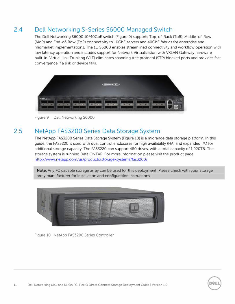
2.5 NetApp FAS3200 Series Data Storage System The NetApp FAS3200 Series Data Storage System (Figure 10) is a midrange data storage platform. In this
guide, the FAS3220 is used with dual control enclosures for high availability (HA) and expanded I/O for
additional storage capacity. The FAS3220 can support 480 drives, with a total capacity of 1,920TB. The
storage system is running Data ONTAP. For more information please visit the product page:
http://www.netapp.com/us/products/storage-systems/fas3200/
Note: Any FC capable storage array can be used for this deployment. Please check with your storage
array manufacturer for installation and configuration instructions.
Figure 10 NetApp FAS3200 Series Controller
12 Dell Networking MXL and M IOA FC-FlexIO Direct Connect Storage Deployment Guide | Version 1.0
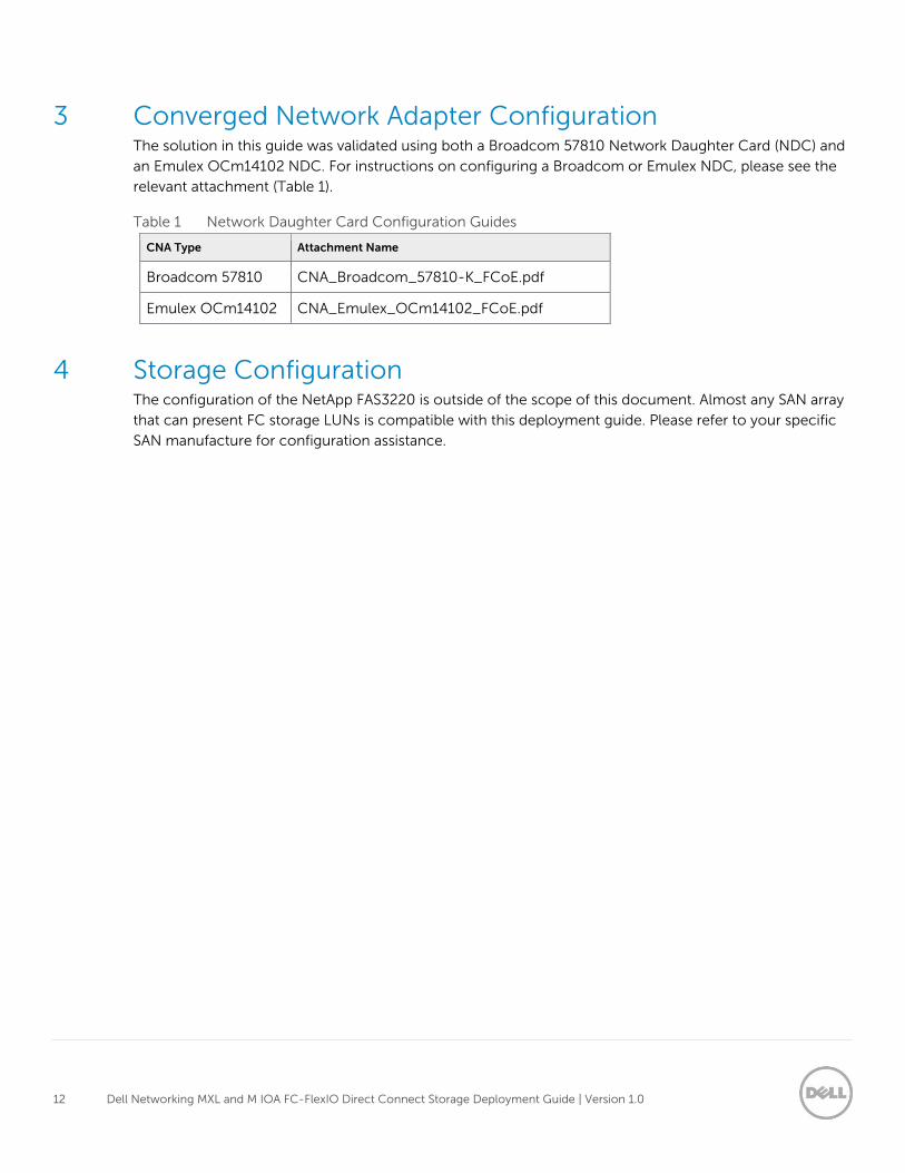
3 Converged Network Adapter Configuration The solution in this guide was validated using both a Broadcom 57810 Network Daughter Card (NDC) and
an Emulex OCm14102 NDC. For instructions on configuring a Broadcom or Emulex NDC, please see the
relevant attachment (Table 1).
Table 1 Network Daughter Card Configuration Guides
CNA Type Attachment Name
Broadcom 57810 CNA_Broadcom_57810-K_FCoE.pdf
Emulex OCm14102 CNA_Emulex_OCm14102_FCoE.pdf
4 Storage Configuration The configuration of the NetApp FAS3220 is outside of the scope of this document. Almost any SAN array
that can present FC storage LUNs is compatible with this deployment guide. Please refer to your specific
SAN manufacture for configuration assistance.
13 Dell Networking MXL and M IOA FC-FlexIO Direct Connect Storage Deployment Guide | Version 1.0
5 Switch Configurations The CLI configuration for the MXLs and M IOAs is presented in this section. The main focus of this
deployment guide is the storage configuration. The Ethernet configuration is lightly touched upon,
focusing on enabling uplink interfaces to the S6000 Top of Rack (ToR) switches.
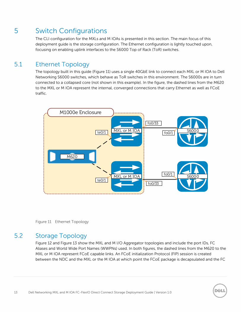
5.1 Ethernet Topology The topology built in this guide (Figure 11) uses a single 40GbE link to connect each MXL or M IOA to Dell
Networking S6000 switches, which behave as ToR switches in this environment. The S6000s are in turn
connected to a collapsed core (not shown in this example). In the figure, the dashed lines from the M620
to the MXL or M IOA represent the internal, converged connections that carry Ethernet as well as FCoE
traffic.
M1000e Enclosure
MXL or M IOA
MXL or M IOA B300-2S6000
M620
S6000te0/1
te0/1
fo0/33
fo0/1
fo0/33
fo0/1
Figure 11 Ethernet Topology
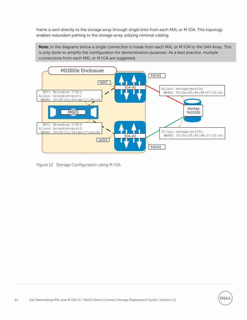
5.2 Storage Topology Figure 12 and Figure 13 show the MXL and M I/O Aggregator topologies and include the port IDs, FC
Aliases and World Wide Port Names (WWPNs) used. In both figures, the dashed lines from the M620 to the
MXL or M IOA represent FCoE capable links. An FCoE initialization Protocol (FIP) session is created
between the NDC and the MXL or the M IOA at which point the FCoE package is decapsulated and the FC
14 Dell Networking MXL and M IOA FC-FlexIO Direct Connect Storage Deployment Guide | Version 1.0
frame is sent directly to the storage array through single links from each MXL or M IOA. This topology
enables redundant pathing to the storage array utilizing minimal cabling.
Note: In the diagrams below a single connection is made from each MXL or M IOA to the SAN Array. This
is only done to simplify the configuration for demonstration purposes. As a best practice, multiple
connections from each MXL or M IOA are suggested.
IOA-A1
IOA-A2
M1000e EnclosureFi0/41
Fi0/41
NetAppFAS3200
te0/1
te0/1
Alias: netapp-port0d
WWPN: 50:0a:09:86:88:57:01:6c
Alias: netapp-port0c
WWPN: 50:0a:09:85:88:57:01:6c
NDC: Broadcom 57810
Alias: broadcom-port1
WWPN: 20:00:5c:f9:dd:17:68:cd
NDC: Broadcom 57810
Alias: broadcom-port2
WWPN: 20:00:5c:f9:dd:17:5e:06
Figure 12 Storage Configuration using M IOA
15 Dell Networking MXL and M IOA FC-FlexIO Direct Connect Storage Deployment Guide | Version 1.0
MXL-A1
MXL-A2
M1000e EnclosureFi0/41
Fi0/41
NetAppFAS3200
te0/1
te0/1
Alias: netapp-port0d
WWPN: 50:0a:09:84:98:52:26:f2
Alias: netapp-port0c
WWPN: 50:0a:09:83:98:52:26:f2
NDC: Emulex OCm14102
Alias: emulex-port1
WWPN: 10:00:00:90:fa:51:1a:35
NDC: Emulex OCm14102
Alias: emulex-port2
WWPN: 10:00:00:90:fa:51:1a:39
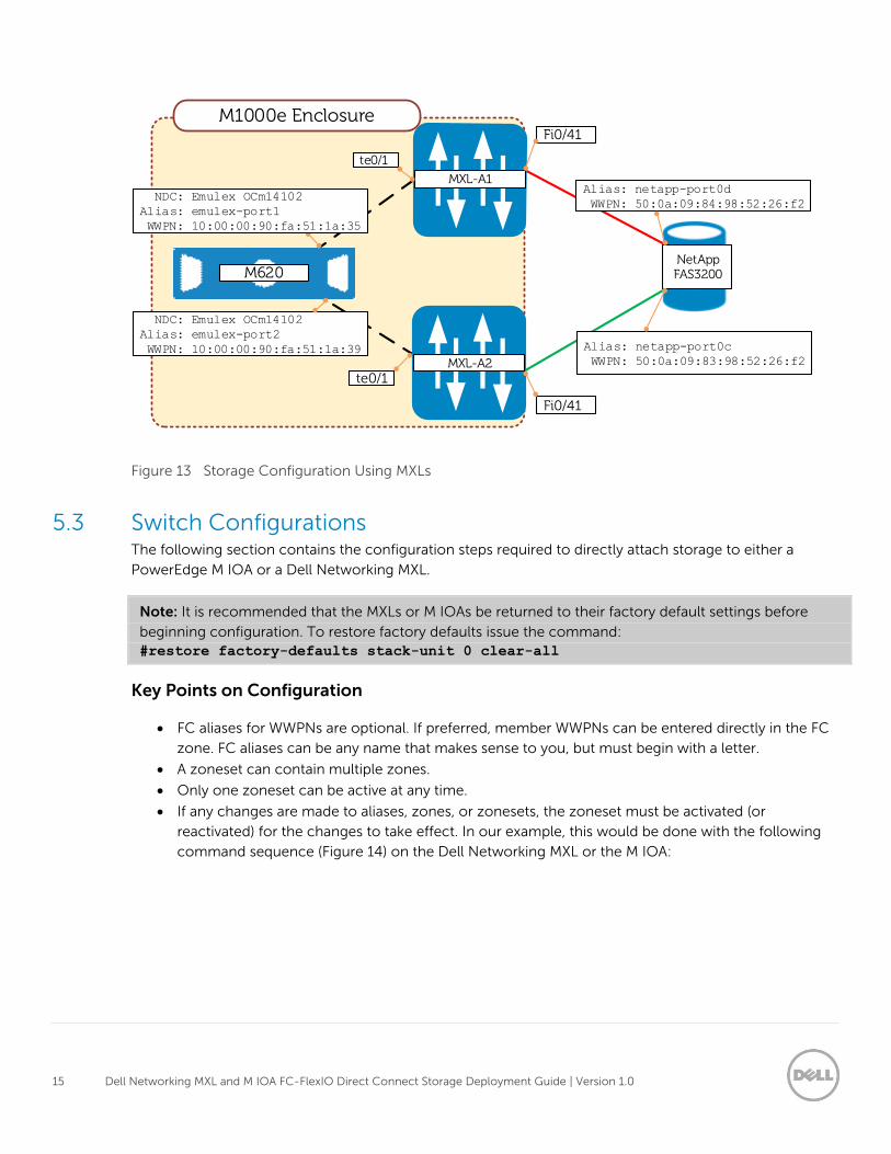
Figure 13 Storage Configuration Using MXLs
5.3 Switch Configurations The following section contains the configuration steps required to directly attach storage to either a
PowerEdge M IOA or a Dell Networking MXL.
Note: It is recommended that the MXLs or M IOAs be returned to their factory default settings before
beginning configuration. To restore factory defaults issue the command:
#restore factory-defaults stack-unit 0 clear-all
Key Points on Configuration
FC aliases for WWPNs are optional. If preferred, member WWPNs can be entered directly in the FC
zone. FC aliases can be any name that makes sense to you, but must begin with a letter.
A zoneset can contain multiple zones.
Only one zoneset can be active at any time.
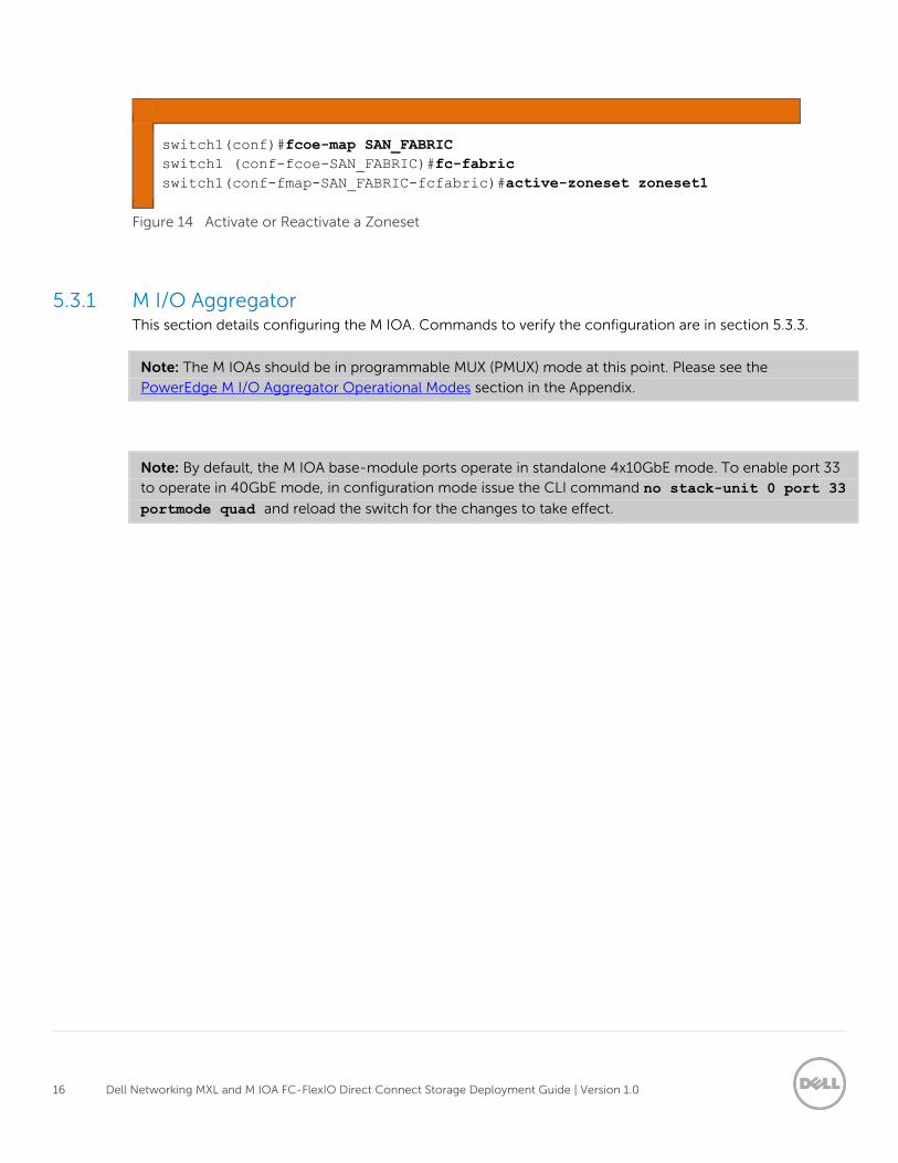
If any changes are made to aliases, zones, or zonesets, the zoneset must be activated (or
reactivated) for the changes to take effect. In our example, this would be done with the following
command sequence (Figure 14) on the Dell Networking MXL or the M IOA:
16 Dell Networking MXL and M IOA FC-FlexIO Direct Connect Storage Deployment Guide | Version 1.0
switch1(conf)#fcoe-map SAN_FABRIC
switch1 (conf-fcoe-SAN_FABRIC)#fc-fabric
switch1(conf-fmap-SAN_FABRIC-fcfabric)#active-zoneset zoneset1
Figure 14 Activate or Reactivate a Zoneset
5.3.1 M I/O Aggregator This section details configuring the M IOA. Commands to verify the configuration are in section 5.3.3.
Note: The M IOAs should be in programmable MUX (PMUX) mode at this point. Please see the
PowerEdge M I/O Aggregator Operational Modes section in the Appendix.
Note: By default, the M IOA base-module ports operate in standalone 4x10GbE mode. To enable port 33
to operate in 40GbE mode, in configuration mode issue the CLI command no stack-unit 0 port 33
portmode quad and reload the switch for the changes to take effect.
17 Dell Networking MXL and M IOA FC-FlexIO Direct Connect Storage Deployment Guide | Version 1.0
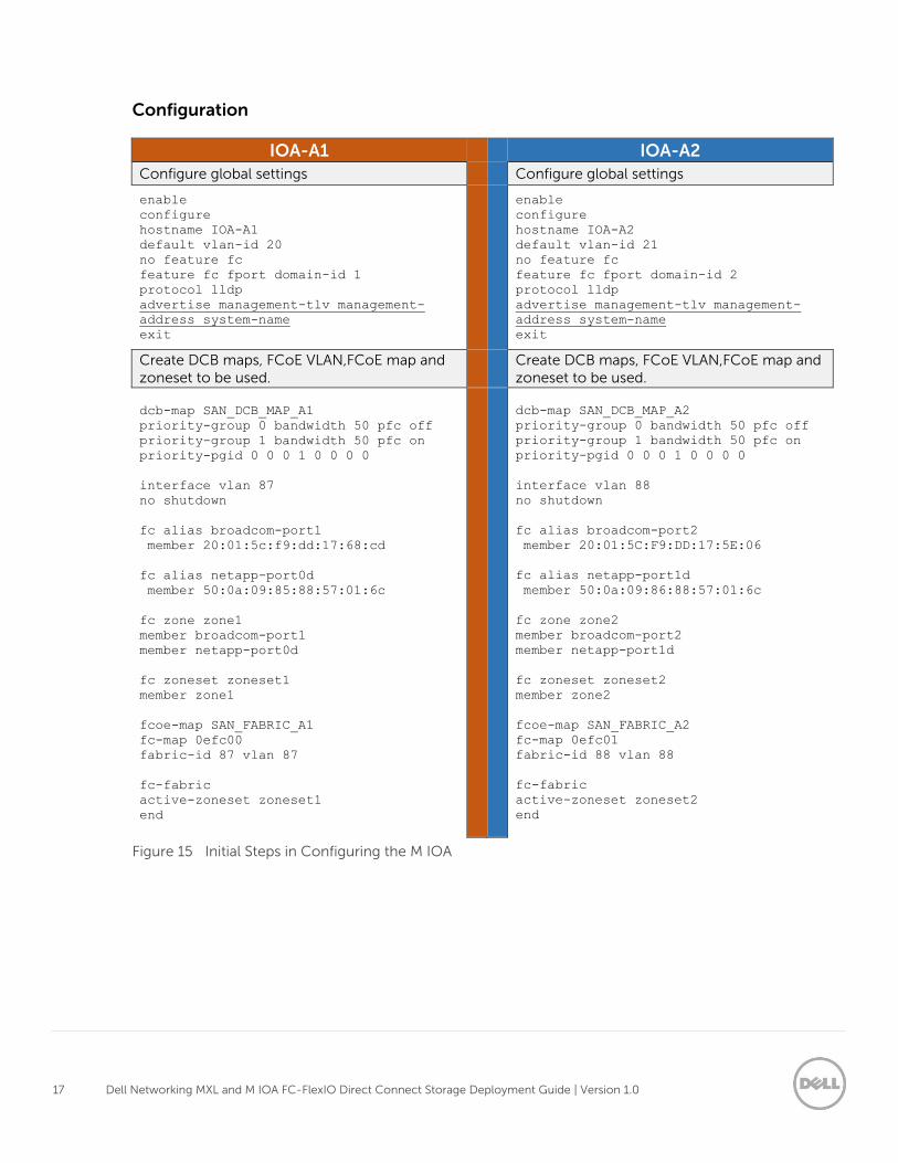
Configuration
IOA-A1 IOA-A2
Configure global settings Configure global settings
enable
configure
hostname IOA-A1
default vlan-id 20
no feature fc
feature fc fport domain-id 1
protocol lldp
advertise management-tlv management-
address system-name
exit
enable
configure
hostname IOA-A2
default vlan-id 21
no feature fc
feature fc fport domain-id 2
protocol lldp
advertise management-tlv management-
address system-name
exit
Create DCB maps, FCoE VLAN,FCoE map and zoneset to be used.
Create DCB maps, FCoE VLAN,FCoE map and zoneset to be used.
dcb-map SAN_DCB_MAP_A1
priority-group 0 bandwidth 50 pfc off
priority-group 1 bandwidth 50 pfc on
priority-pgid 0 0 0 1 0 0 0 0
interface vlan 87
no shutdown
fc alias broadcom-port1
member 20:01:5c:f9:dd:17:68:cd
fc alias netapp-port0d
member 50:0a:09:85:88:57:01:6c
fc zone zone1
member broadcom-port1
member netapp-port0d
fc zoneset zoneset1
member zone1
fcoe-map SAN_FABRIC_A1
fc-map 0efc00
fabric-id 87 vlan 87
fc-fabric
active-zoneset zoneset1
end
dcb-map SAN_DCB_MAP_A2
priority-group 0 bandwidth 50 pfc off
priority-group 1 bandwidth 50 pfc on
priority-pgid 0 0 0 1 0 0 0 0
interface vlan 88
no shutdown
fc alias broadcom-port2
member 20:01:5C:F9:DD:17:5E:06
fc alias netapp-port1d
member 50:0a:09:86:88:57:01:6c
fc zone zone2
member broadcom-port2
member netapp-port1d
fc zoneset zoneset2
member zone2
fcoe-map SAN_FABRIC_A2
fc-map 0efc01
fabric-id 88 vlan 88
fc-fabric
active-zoneset zoneset2
end
Figure 15 Initial Steps in Configuring the M IOA
18 Dell Networking MXL and M IOA FC-FlexIO Direct Connect Storage Deployment Guide | Version 1.0
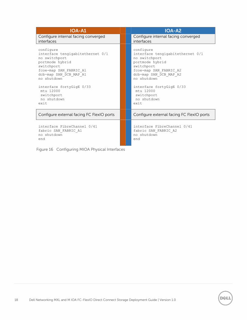
IOA-A1 IOA-A2 Configure internal facing converged interfaces
Configure internal facing converged interfaces
configure
interface tengigabitethernet 0/1
no switchport
portmode hybrid
switchport
fcoe-map SAN_FABRIC_A1
dcb-map SAN_DCB_MAP_A1
no shutdown
interface fortyGigE 0/33
mtu 12000
switchport
no shutdown
exit
configure
interface tengigabitethernet 0/1
no switchport
portmode hybrid
switchport
fcoe-map SAN_FABRIC_A2
dcb-map SAN_DCB_MAP_A2
no shutdown
interface fortyGigE 0/33
mtu 12000
switchport
no shutdown
exit
Configure external facing FC FlexIO ports Configure external facing FC FlexIO ports
interface FibreChannel 0/41
fabric SAN_FABRIC_A1
no shutdown
end
interface FibreChannel 0/41
fabric SAN_FABRIC_A2
no shutdown
end
Figure 16 Configuring MIOA Physical Interfaces
19 Dell Networking MXL and M IOA FC-FlexIO Direct Connect Storage Deployment Guide | Version 1.0
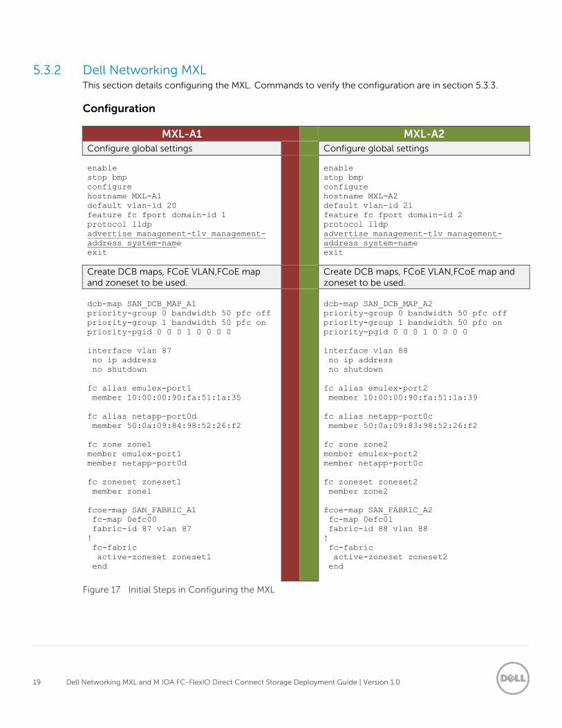
5.3.2 Dell Networking MXL This section details configuring the MXL. Commands to verify the configuration are in section 5.3.3.
Configuration
MXL-A1 MXL-A2
Configure global settings Configure global settings
enable
stop bmp
configure
hostname MXL-A1
default vlan-id 20
feature fc fport domain-id 1
protocol lldp
advertise management-tlv management-
address system-name
exit
enable
stop bmp
configure
hostname MXL-A2
default vlan-id 21
feature fc fport domain-id 2
protocol lldp
advertise management-tlv management-
address system-name
exit
Create DCB maps, FCoE VLAN,FCoE map and zoneset to be used.
Create DCB maps, FCoE VLAN,FCoE map and zoneset to be used.
dcb-map SAN_DCB_MAP_A1
priority-group 0 bandwidth 50 pfc off
priority-group 1 bandwidth 50 pfc on
priority-pgid 0 0 0 1 0 0 0 0
interface vlan 87
no ip address
no shutdown
fc alias emulex-port1
member 10:00:00:90:fa:51:1a:35
fc alias netapp-port0d
member 50:0a:09:84:98:52:26:f2
fc zone zone1
member emulex-port1
member netapp-port0d
fc zoneset zoneset1
member zone1
fcoe-map SAN_FABRIC_A1
fc-map 0efc00
fabric-id 87 vlan 87
!
fc-fabric
active-zoneset zoneset1
end
dcb-map SAN_DCB_MAP_A2
priority-group 0 bandwidth 50 pfc off
priority-group 1 bandwidth 50 pfc on
priority-pgid 0 0 0 1 0 0 0 0
interface vlan 88
no ip address
no shutdown
fc alias emulex-port2
member 10:00:00:90:fa:51:1a:39
fc alias netapp-port0c
member 50:0a:09:83:98:52:26:f2
fc zone zone2
member emulex-port2
member netapp-port0c
fc zoneset zoneset2
member zone2
fcoe-map SAN_FABRIC_A2
fc-map 0efc01
fabric-id 88 vlan 88
!
fc-fabric
active-zoneset zoneset2
end
Figure 17 Initial Steps in Configuring the MXL
20 Dell Networking MXL and M IOA FC-FlexIO Direct Connect Storage Deployment Guide | Version 1.0
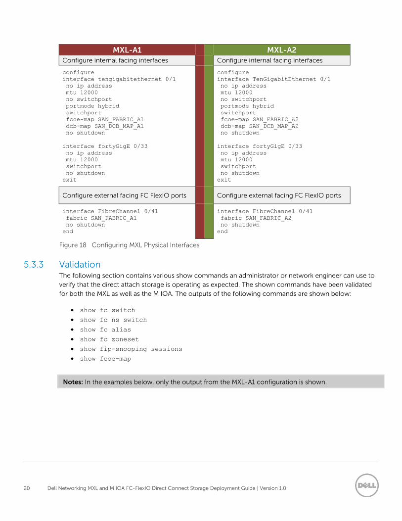
MXL-A1 MXL-A2
Configure internal facing interfaces Configure internal facing interfaces
configure
interface tengigabitethernet 0/1
no ip address
mtu 12000
no switchport
portmode hybrid
switchport
fcoe-map SAN_FABRIC_A1
dcb-map SAN_DCB_MAP_A1
no shutdown
interface fortyGigE 0/33
no ip address
mtu 12000
switchport
no shutdown
exit
configure
interface TenGigabitEthernet 0/1
no ip address
mtu 12000
no switchport
portmode hybrid
switchport
fcoe-map SAN_FABRIC_A2
dcb-map SAN_DCB_MAP_A2
no shutdown
interface fortyGigE 0/33
no ip address
mtu 12000
switchport
no shutdown
exit
Configure external facing FC FlexIO ports Configure external facing FC FlexIO ports
interface FibreChannel 0/41
fabric SAN_FABRIC_A1
no shutdown
end
interface FibreChannel 0/41
fabric SAN_FABRIC_A2
no shutdown
end
Figure 18 Configuring MXL Physical Interfaces
5.3.3 Validation The following section contains various show commands an administrator or network engineer can use to
verify that the direct attach storage is operating as expected. The shown commands have been validated
for both the MXL as well as the M IOA. The outputs of the following commands are shown below:
show fc switch
show fc ns switch
show fc alias
show fc zoneset
show fip-snooping sessions
show fcoe-map
Notes: In the examples below, only the output from the MXL-A1 configuration is shown.
21 Dell Networking MXL and M IOA FC-FlexIO Direct Connect Storage Deployment Guide | Version 1.0
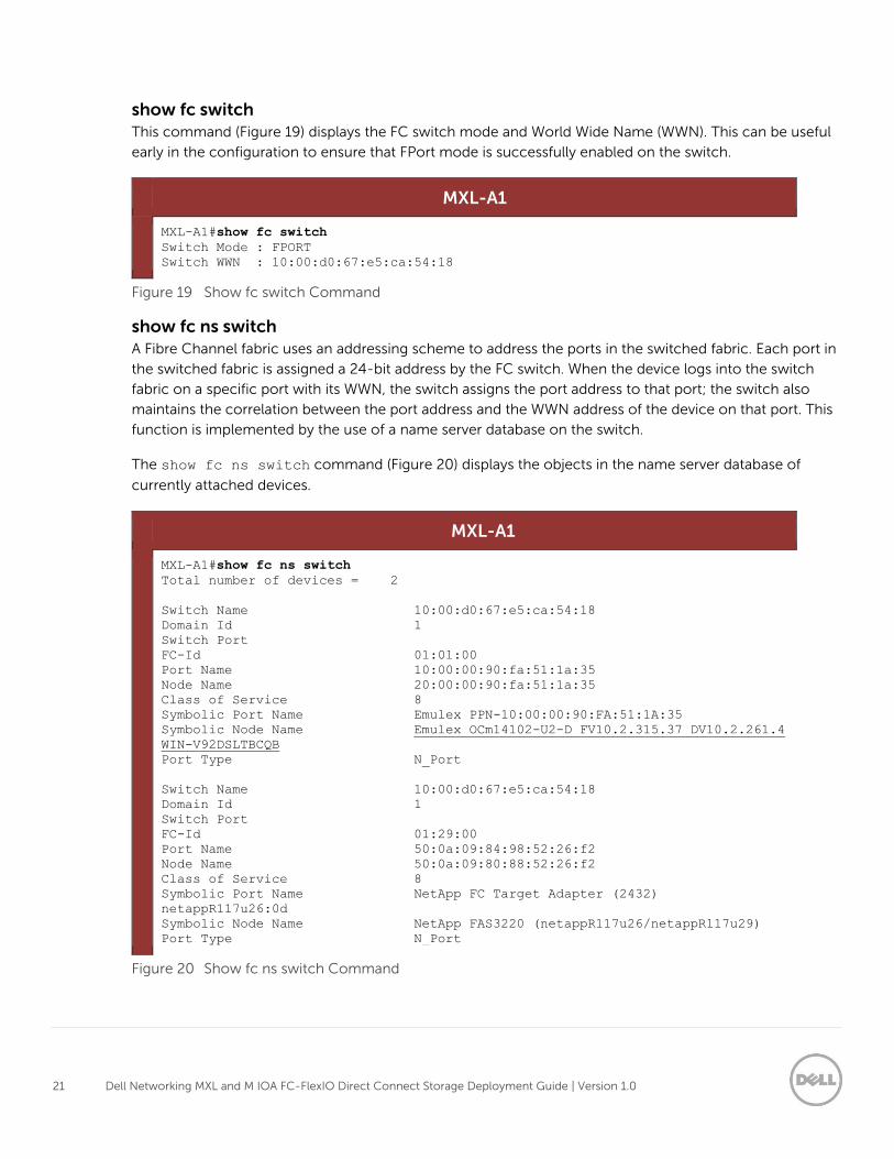
show fc switch
This command (Figure 19) displays the FC switch mode and World Wide Name (WWN). This can be useful
early in the configuration to ensure that FPort mode is successfully enabled on the switch.
MXL-A1
MXL-A1#show fc switch
Switch Mode : FPORT
Switch WWN : 10:00:d0:67:e5:ca:54:18
Figure 19 Show fc switch Command
show fc ns switch
A Fibre Channel fabric uses an addressing scheme to address the ports in the switched fabric. Each port in
the switched fabric is assigned a 24-bit address by the FC switch. When the device logs into the switch
fabric on a specific port with its WWN, the switch assigns the port address to that port; the switch also
maintains the correlation between the port address and the WWN address of the device on that port. This
function is implemented by the use of a name server database on the switch.
The show fc ns switch command (Figure 20) displays the objects in the name server database of
currently attached devices.
MXL-A1
MXL-A1#show fc ns switch
Total number of devices = 2
Switch Name 10:00:d0:67:e5:ca:54:18
Domain Id 1
Switch Port
FC-Id 01:01:00
Port Name 10:00:00:90:fa:51:1a:35
Node Name 20:00:00:90:fa:51:1a:35
Class of Service 8
Symbolic Port Name Emulex PPN-10:00:00:90:FA:51:1A:35
Symbolic Node Name Emulex OCm14102-U2-D FV10.2.315.37 DV10.2.261.4
WIN-V92DSLTBCQB
Port Type N_Port
Switch Name 10:00:d0:67:e5:ca:54:18
Domain Id 1
Switch Port
FC-Id 01:29:00
Port Name 50:0a:09:84:98:52:26:f2
Node Name 50:0a:09:80:88:52:26:f2
Class of Service 8
Symbolic Port Name NetApp FC Target Adapter (2432)
netappR117u26:0d
Symbolic Node Name NetApp FAS3220 (netappR117u26/netappR117u29)
Port Type N_Port
Figure 20 Show fc ns switch Command
22 Dell Networking MXL and M IOA FC-FlexIO Direct Connect Storage Deployment Guide | Version 1.0
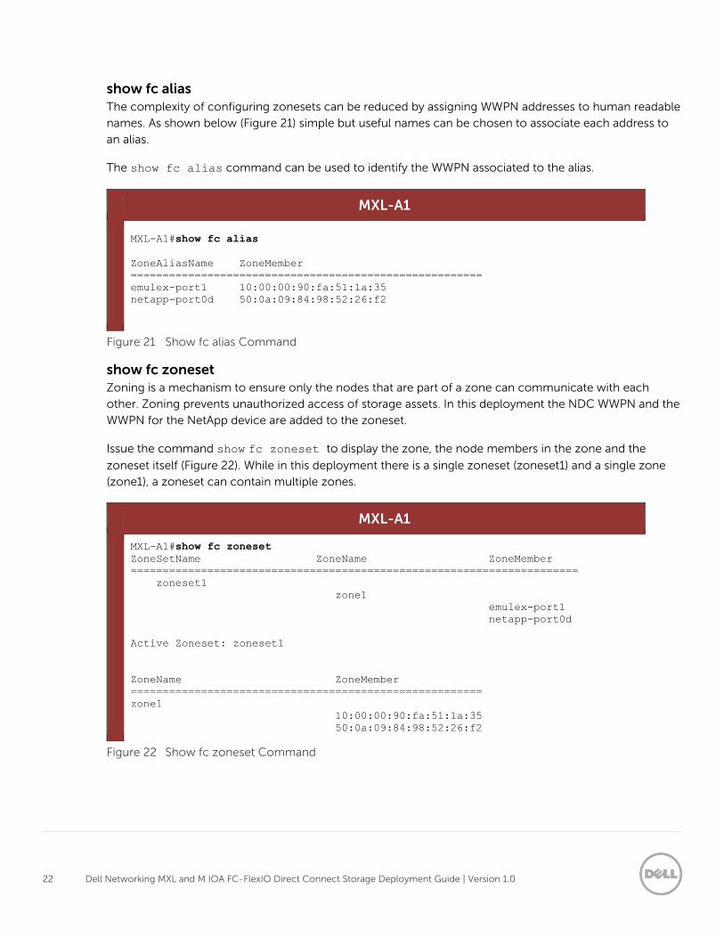
show fc alias
The complexity of configuring zonesets can be reduced by assigning WWPN addresses to human readable
names. As shown below (Figure 21) simple but useful names can be chosen to associate each address to
an alias.
The show fc alias command can be used to identify the WWPN associated to the alias.
MXL-A1
MXL-A1#show fc alias
ZoneAliasName ZoneMember
=======================================================
emulex-port1 10:00:00:90:fa:51:1a:35
netapp-port0d 50:0a:09:84:98:52:26:f2
Figure 21 Show fc alias Command
show fc zoneset
Zoning is a mechanism to ensure only the nodes that are part of a zone can communicate with each
other. Zoning prevents unauthorized access of storage assets. In this deployment the NDC WWPN and the
WWPN for the NetApp device are added to the zoneset.
Issue the command show fc zoneset to display the zone, the node members in the zone and the
zoneset itself (Figure 22). While in this deployment there is a single zoneset (zoneset1) and a single zone
(zone1), a zoneset can contain multiple zones.
MXL-A1
MXL-A1#show fc zoneset
ZoneSetName ZoneName ZoneMember
======================================================================
zoneset1
zone1
emulex-port1
netapp-port0d
Active Zoneset: zoneset1
ZoneName ZoneMember
=======================================================
zone1
10:00:00:90:fa:51:1a:35
50:0a:09:84:98:52:26:f2
Figure 22 Show fc zoneset Command
23 Dell Networking MXL and M IOA FC-FlexIO Direct Connect Storage Deployment Guide | Version 1.0
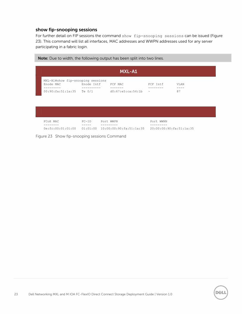
show fip-snooping sessions
For further detail on FIP sessions the command show fip-snooping sessions can be issued (Figure
23). This command will list all interfaces, MAC addresses and WWPN addresses used for any server
participating in a fabric login.
Note: Due to width, the following output has been split into two lines.
MXL-A1
MXL-A1#show fip-snooping sessions
Enode MAC Enode Intf FCF MAC FCF Intf VLAN
--------- ---------- ------- -------- ----
00:90:fa:51:1a:35 Te 0/1 d0:67:e5:ca:54:1b ~ 87
FCoE MAC FC-ID Port WWPN Port WWNN
-------- ----- --------- ---------
0e:fc:00:01:01:00 01:01:00 10:00:00:90:fa:51:1a:35 20:00:00:90:fa:51:1a:35
Figure 23 Show fip-snooping sessions Command
24 Dell Networking MXL and M IOA FC-FlexIO Direct Connect Storage Deployment Guide | Version 1.0
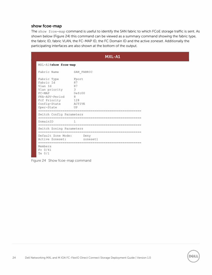
show fcoe-map
The show fcoe-map command is useful to identify the SAN fabric to which FCoE storage traffic is sent. As
shown below (Figure 24) this command can be viewed as a summary command showing the fabric type,
the fabric ID, fabric VLAN, the FC-MAP ID, the FC Domain ID and the active zoneset. Additionally the
participating interfaces are also shown at the bottom of the output.
MXL-A1
MXL-A1#show fcoe-map
Fabric Name SAN_FABRIC
Fabric Type Fport
Fabric Id 87
Vlan Id 87
Vlan priority 3
FC-MAP 0efc00
FKA-ADV-Period 8
Fcf Priority 128
Config-State ACTIVE
Oper-State UP
=======================================================
Switch Config Parameters
=======================================================
DomainID 1
=======================================================
Switch Zoning Parameters
=======================================================
Default Zone Mode: Deny
Active Zoneset: zoneset1
=======================================================
Members
Fc 0/41
Te 0/1
Figure 24 Show fcoe-map command
25 Dell Networking MXL and M IOA FC-FlexIO Direct Connect Storage Deployment Guide | Version 1.0
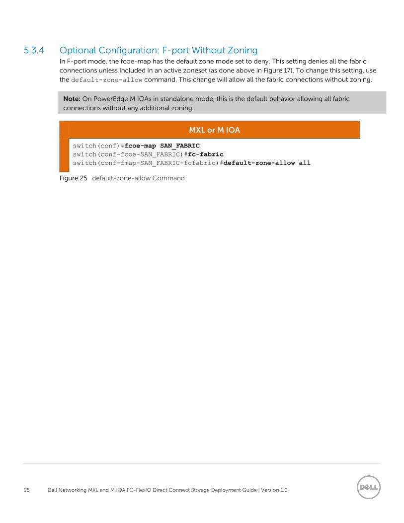
5.3.4 Optional Configuration: F-port Without Zoning In F-port mode, the fcoe-map has the default zone mode set to deny. This setting denies all the fabric
connections unless included in an active zoneset (as done above in Figure 17). To change this setting, use
the default-zone-allow command. This change will allow all the fabric connections without zoning.
Note: On PowerEdge M IOAs in standalone mode, this is the default behavior allowing all fabric
connections without any additional zoning.
MXL or M IOA
switch(conf)#fcoe-map SAN_FABRIC
switch(conf-fcoe-SAN_FABRIC)#fc-fabric
switch(conf-fmap-SAN_FABRIC-fcfabric)#default-zone-allow all
Figure 25 default-zone-allow Command
26 Dell Networking MXL and M IOA FC-FlexIO Direct Connect Storage Deployment Guide | Version 1.0
6 Server Configuration In this section, in order to meet the needs of the environment, two different server configurations are
presented. The first configuration covers installing, configuring and validating VMware ESXi. The second
covers configuring and verifying the function of Multipath I/O (MPIO) inside Windows Server 2012 R2.
6.1 VMware ESXi 5.5 - Installation, Configuration and Validation This section will guide you through downloading, installing and basic configuration of the Dell custom
ESXi 5.5 Update 2 image, which can be download from support.dell.com. The ISO will need to be
downloaded and either burned to a CD or a third party utility used to create a bootable USB key.
Installing Dell Custom VMware ESXi 5.5 U2
This section provides an outline of the installation process for VMware ESXI 5.5 U2. For further in-depth
information on the installation of ESXi, please visit the VMware vSphere 5.5 Documentation Center at
https://pubs.vmware.com/vsphere-55/index.jsp.
1. Insert the Dell custom ESXi 5.5 installation media into the server.
This can either be a CD/DVD, a USB flash drive or mount the installation ISO through the iDRAC
interface for the M620.
2. Set the BIOS to boot from the media. In most cases, this will be Virtual CD.
3. On the Welcome screen, press Enter to continue.
4. On the End User License Agreement (EULA) screen press F11 to accept.
At this point, the installer will scan for suitable installation targets. In this scenario, ESXi is installed
on an internal SD card.
5. Select the keyboard type for the host. This will be US Default in most cases.
6. Enter a password for the host.
7. On the Confirm Installation window, press Enter to start the installation.
8. When the installation is complete, remove the installation CD, DVD, USB flash drive, or unmount
the Virtual CD.
9. Press Enter to reboot the host.
Connecting to the ESXi Host with the vSphere Client
Once installation has been completed, access the console for the host. From here, a management NIC
can be activated and an IP address assigned. Follow the steps below to complete this.
Setting up the Management NIC.
1. Press F2 to Customize System.
2. Select Configure Management Network and press Enter.
3. Select Network Adapters and press Enter.
27 Dell Networking MXL and M IOA FC-FlexIO Direct Connect Storage Deployment Guide | Version 1.0
4. Any NIC that is currently connected with show Connected under Status, use the spacebar to
select the appropriate management NIC.
5. Press Enter to exit.
6. Press Esc.
7. Press Y for Yes to restart the management network.
8. Press Esc to exit System Customization.
Configuring a Static IP Address
1. Press F2 to Customize System.
2. Select Configure Management Network and press Enter.
3. Select IP Configuration and press Enter.
4. Select Set static IP address and networking configuration and press the spacebar.
5. Type in an IP Address, Subnet Mask and Default Gateway and press Enter.
6. Press Esc.
7. Press Y for Yes to restart the management network.
8. Press Esc to exit System Customization.
Connecting to the ESXi host using the vSphere Client
1. Use a web browser to go to http://<IP_of_ESXi_host>.
2. Click on the link Download vSphere Client.
3. Launch the installer, agreeing to all the defaults for installation.
4. Launch the VMware vSphere Client.
5. Enter the IP address of the ESXi host, the username (root) and the password configured
during the installation. Press Enter.
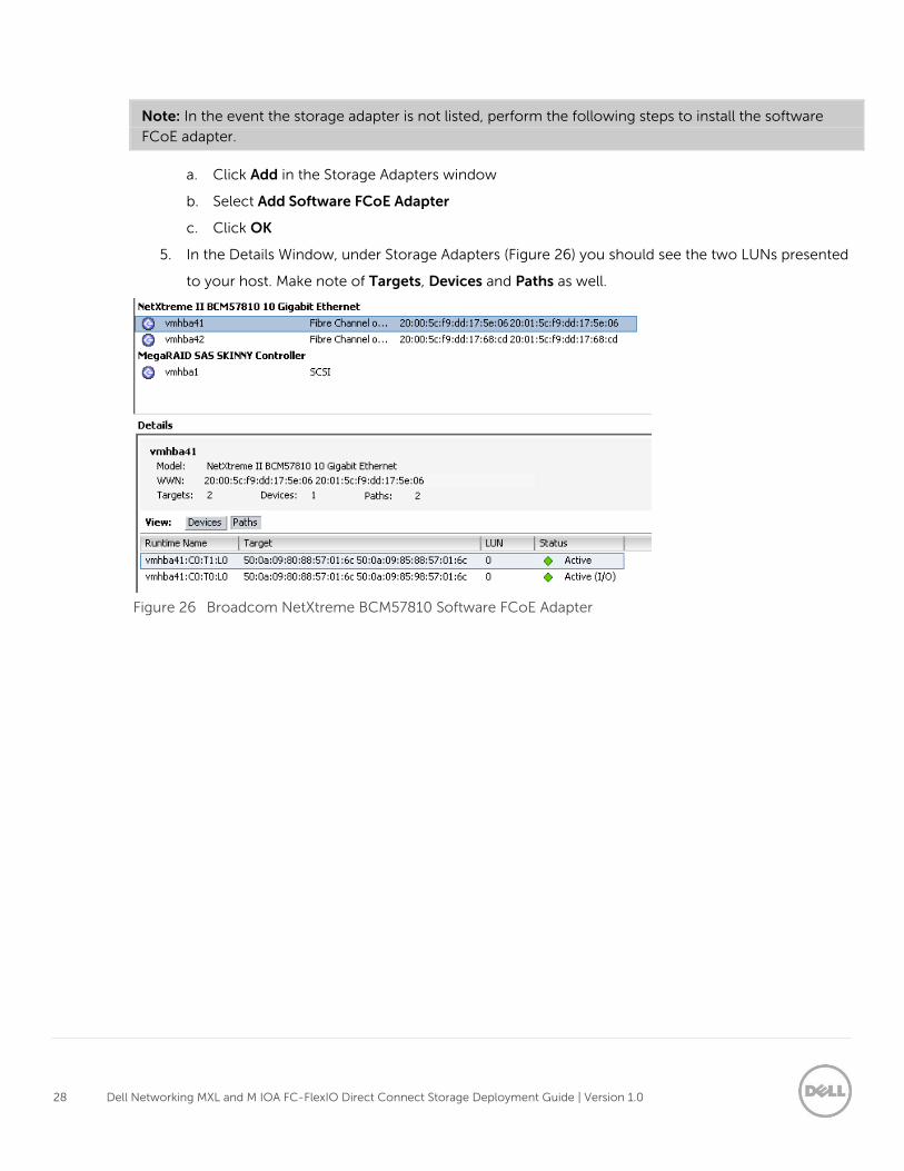
Verifying MPIO Through the vSphere Client
Once connected to the ESXi host through the vSphere Client you can verify that a LUN is presented to the
ESXi host. Additionally you will be able to see the number of paths for each LUN, this is useful in verifying
that both SAN A and SAN B are working. Figure 26 shows the final step, which presents the number of
targets, number of devices and the number of paths.
1. Select your host from the left hand column
2. Click on the Configuration tab
3. Click Storage Adapters under Hardware
4. Locate your CNA in the list of storage adapters
28 Dell Networking MXL and M IOA FC-FlexIO Direct Connect Storage Deployment Guide | Version 1.0
Note: In the event the storage adapter is not listed, perform the following steps to install the software
FCoE adapter.
a. Click Add in the Storage Adapters window
b. Select Add Software FCoE Adapter
c. Click OK
5. In the Details Window, under Storage Adapters (Figure 26) you should see the two LUNs presented
to your host. Make note of Targets, Devices and Paths as well.
Figure 26 Broadcom NetXtreme BCM57810 Software FCoE Adapter
29 Dell Networking MXL and M IOA FC-FlexIO Direct Connect Storage Deployment Guide | Version 1.0
6.2 Microsoft Server Operating System MPIO Installation and
Configuration Microsoft Multipath I/O (MPIO) must be installed and configured for the Windows operating system to
properly recognize multiple paths to a storage device.
Note: The following steps are specific to Windows Server 2012 R2. Microsoft MPIO is also supported on
Windows Server 2012 (pre-R2), 2008 and 2008 R2. The configuration process will be similar for all
versions.
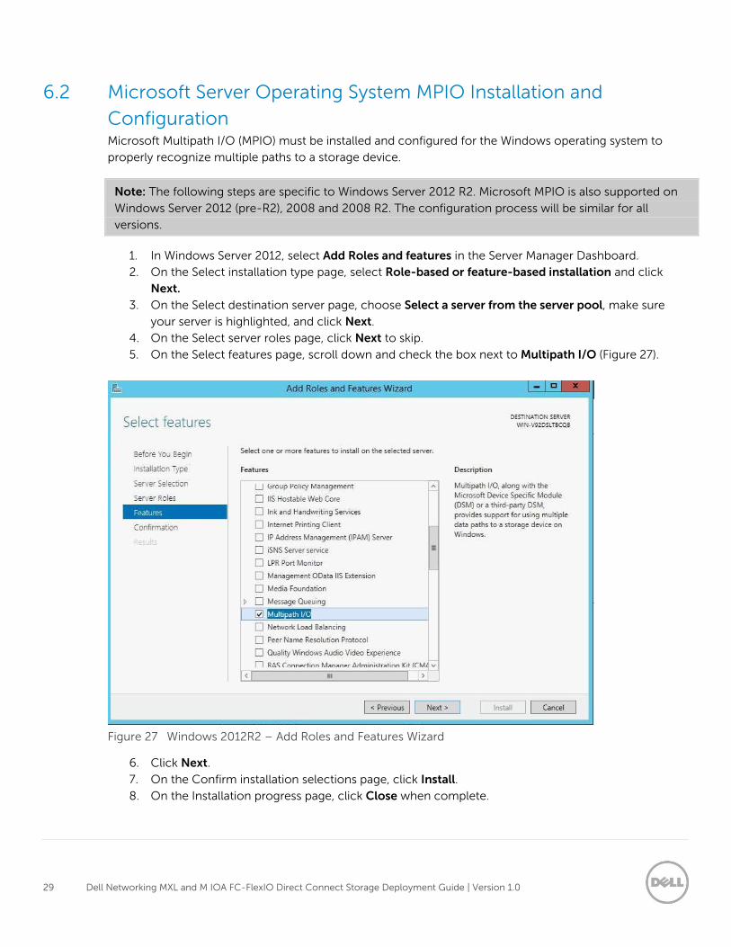
1. In Windows Server 2012, select Add Roles and features in the Server Manager Dashboard.
2. On the Select installation type page, select Role-based or feature-based installation and click
Next.
3. On the Select destination server page, choose Select a server from the server pool, make sure
your server is highlighted, and click Next.
4. On the Select server roles page, click Next to skip.
5. On the Select features page, scroll down and check the box next to Multipath I/O (Figure 27).
Figure 27 Windows 2012R2 – Add Roles and Features Wizard
6. Click Next.
7. On the Confirm installation selections page, click Install.
8. On the Installation progress page, click Close when complete.
30 Dell Networking MXL and M IOA FC-FlexIO Direct Connect Storage Deployment Guide | Version 1.0
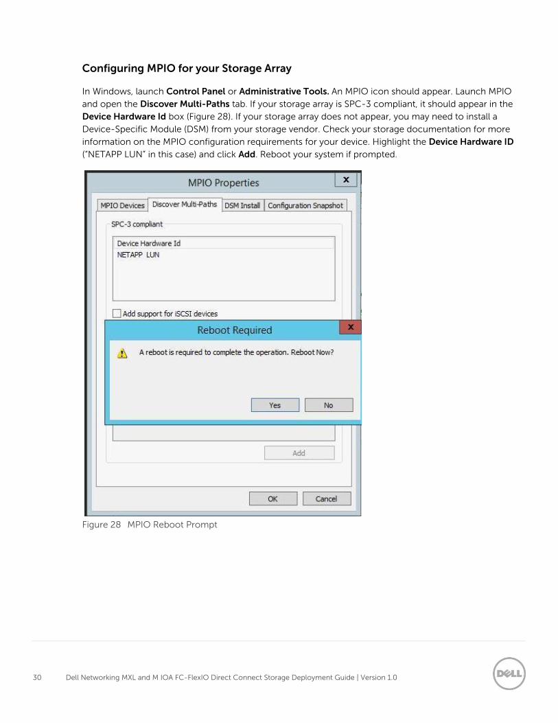
Configuring MPIO for your Storage Array
In Windows, launch Control Panel or Administrative Tools. An MPIO icon should appear. Launch MPIO
and open the Discover Multi-Paths tab. If your storage array is SPC-3 compliant, it should appear in the
Device Hardware Id box (Figure 28). If your storage array does not appear, you may need to install a
Device-Specific Module (DSM) from your storage vendor. Check your storage documentation for more
information on the MPIO configuration requirements for your device. Highlight the Device Hardware ID
(“NETAPP LUN” in this case) and click Add. Reboot your system if prompted.
Figure 28 MPIO Reboot Prompt
31 Dell Networking MXL and M IOA FC-FlexIO Direct Connect Storage Deployment Guide | Version 1.0
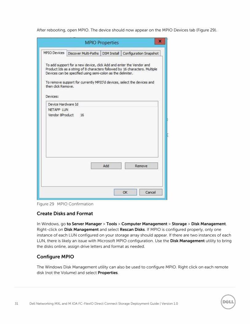
After rebooting, open MPIO. The device should now appear on the MPIO Devices tab (Figure 29).
Figure 29 MPIO Confirmation
Create Disks and Format
In Windows, go to Server Manager > Tools > Computer Management > Storage > Disk Management.
Right-click on Disk Management and select Rescan Disks. If MPIO is configured properly, only one
instance of each LUN configured on your storage array should appear. If there are two instances of each
LUN, there is likely an issue with Microsoft MPIO configuration. Use the Disk Management utility to bring
the disks online, assign drive letters and format as needed.
Configure MPIO
The Windows Disk Management utility can also be used to configure MPIO. Right click on each remote
disk (not the Volume) and select Properties.
32 Dell Networking MXL and M IOA FC-FlexIO Direct Connect Storage Deployment Guide | Version 1.0
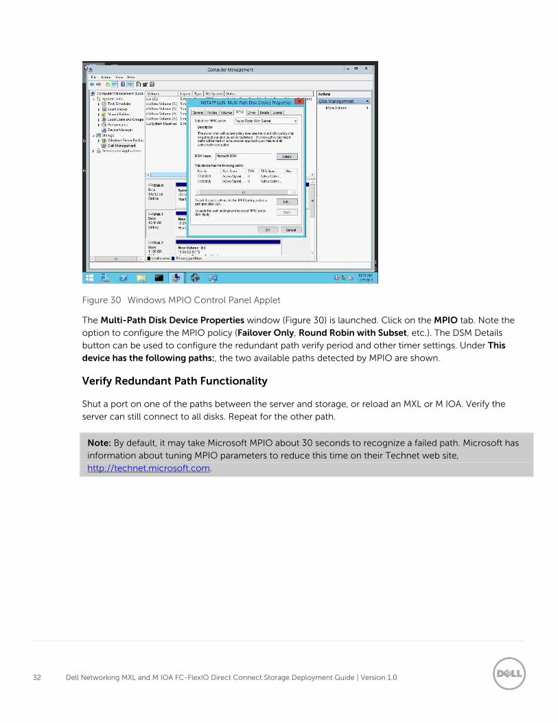
Figure 30 Windows MPIO Control Panel Applet
The Multi-Path Disk Device Properties window (Figure 30) is launched. Click on the MPIO tab. Note the
option to configure the MPIO policy (Failover Only, Round Robin with Subset, etc.). The DSM Details
button can be used to configure the redundant path verify period and other timer settings. Under This
device has the following paths:, the two available paths detected by MPIO are shown.
Verify Redundant Path Functionality
Shut a port on one of the paths between the server and storage, or reload an MXL or M IOA. Verify the
server can still connect to all disks. Repeat for the other path.
Note: By default, it may take Microsoft MPIO about 30 seconds to recognize a failed path. Microsoft has
information about tuning MPIO parameters to reduce this time on their Technet web site,
http://technet.microsoft.com.
33 Dell Networking MXL and M IOA FC-FlexIO Direct Connect Storage Deployment Guide | Version 1.0
7 Conclusion Dell Networking MXL and M I/O Aggregator with installed FC FlexIO provide a reliable and evolutionary
step in the right direction for lowering the necessary Data Center costs typically associated with storage
and for providing an easy to use configuration. The Direct-connect topologies will ease switch needs and
bring great benefits in today’s converged infrastructure.
34 Dell Networking MXL and M IOA FC-FlexIO Direct Connect Storage Deployment Guide | Version 1.0
A Appendix
A.1 Configuration Details
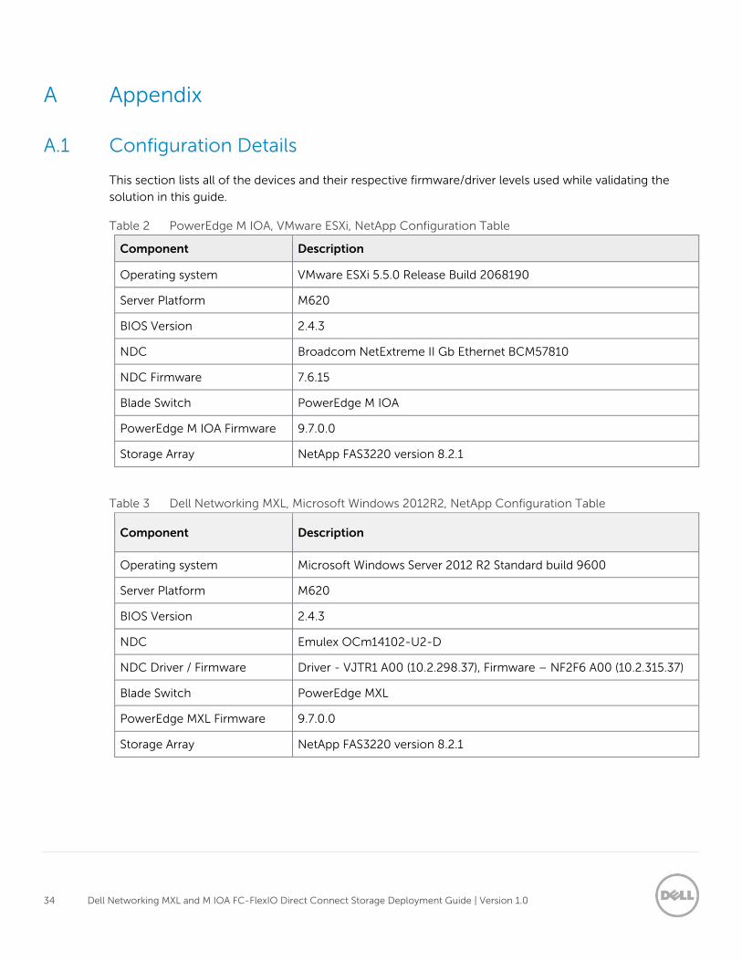
This section lists all of the devices and their respective firmware/driver levels used while validating the
solution in this guide.
Table 2 PowerEdge M IOA, VMware ESXi, NetApp Configuration Table
Component Description
Operating system VMware ESXi 5.5.0 Release Build 2068190
Server Platform M620
BIOS Version 2.4.3
NDC Broadcom NetExtreme II Gb Ethernet BCM57810
NDC Firmware 7.6.15
Blade Switch PowerEdge M IOA
PowerEdge M IOA Firmware 9.7.0.0
Storage Array NetApp FAS3220 version 8.2.1
Table 3 Dell Networking MXL, Microsoft Windows 2012R2, NetApp Configuration Table
Component Description
Operating system Microsoft Windows Server 2012 R2 Standard build 9600
Server Platform M620
BIOS Version 2.4.3
NDC Emulex OCm14102-U2-D
NDC Driver / Firmware Driver - VJTR1 A00 (10.2.298.37), Firmware – NF2F6 A00 (10.2.315.37)
Blade Switch PowerEdge MXL
PowerEdge MXL Firmware 9.7.0.0
Storage Array NetApp FAS3220 version 8.2.1
35 Dell Networking MXL and M IOA FC-FlexIO Direct Connect Storage Deployment Guide | Version 1.0
A.2 PowerEdge M I/O Aggregator Operational Modes
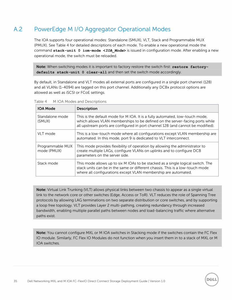
The IOA supports four operational modes: Standalone (SMUX), VLT, Stack and Programmable MUX
(PMUX). See Table 4 for detailed descriptions of each mode. To enable a new operational mode the
command stack-unit 0 iom-mode <IOA_Mode> is issued in configuration mode. After enabling a new
operational mode, the switch must be reloaded.
Note: When switching modes it is important to factory restore the switch first: restore factory-
defaults stack-unit 0 clear-all and then set the switch mode accordingly.
By default, in Standalone and VLT modes all external ports are configured in a single port channel (128)
and all VLANs (1-4094) are tagged on this port channel. Additionally any DCBx protocol options are
allowed as well as iSCSI or FCoE settings.
Table 4 M IOA Modes and Descriptions
IOA Mode Description
Standalone mode (SMUX)
This is the default mode for M IOA. It is a fully automated, low-touch mode, which allows VLAN memberships to be defined on the server-facing ports while all upstream ports are configured in port channel 128 (and cannot be modified).
VLT mode This is a low-touch mode where all configurations except VLAN membership are automated. In this mode, port 9 is dedicated to VLT interconnect.
Programmable MUX mode (PMUX)
This mode provides flexibility of operation by allowing the administrator to create multiple LAGs, configure VLANs on uplinks and to configure DCB parameters on the server side.
Stack mode This mode allows up to six M IOAs to be stacked as a single logical switch. The stack units can be in the same or different chassis. This is a low-touch mode where all configurations except VLAN membership are automated.
Note: Virtual Link Trunking (VLT) allows physical links between two chassis to appear as a single virtual
link to the network core or other switches (Edge, Access or ToR). VLT reduces the role of Spanning Tree
protocols by allowing LAG terminations on two separate distribution or core switches, and by supporting
a loop free topology. VLT provides Layer 2 multi-pathing, creating redundancy through increased
bandwidth, enabling multiple parallel paths between nodes and load-balancing traffic where alternative
paths exist.
Note: You cannot configure MXL or M IOA switches in Stacking mode if the switches contain the FC Flex
IO module. Similarly, FC Flex IO Modules do not function when you insert them in to a stack of MXL or M
IOA switches.
36 Dell Networking MXL and M IOA FC-FlexIO Direct Connect Storage Deployment Guide | Version 1.0
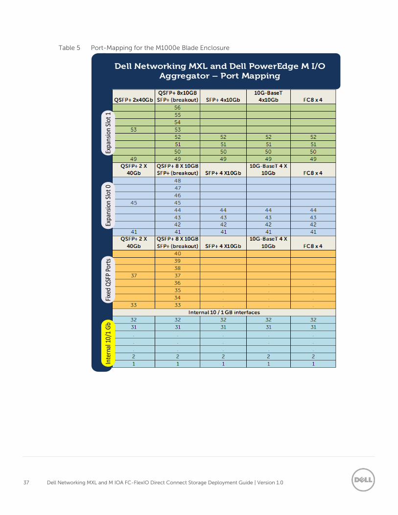
A.3 PowerEdge M1000e Port Mapping
The connections are 10 Gigabit Ethernet connections for basic Ethernet traffic, iSCSI storage traffic or
FCoE storage traffic. In a typical M1000e configuration of 16 half-height blade servers, ports 1-16 are used
and 17 -32 disabled. However if quad port adapters or quarter-height blade servers are used, ports 17-32
will be enabled.
Table 5 lists the port mapping for the two expansion slots on the Dell Networking MXLs and M IOAs as well
as the internal 10/1 GbE interfaces on the blade servers installed in the M1000e chassis. For information on
internal port mapping please see the attachment m1000e_internal_port_mapping.pdf
37 Dell Networking MXL and M IOA FC-FlexIO Direct Connect Storage Deployment Guide | Version 1.0
Table 5 Port-Mapping for the M1000e Blade Enclosure
Dell Networking MXL and Dell PowerEdge M I/O Aggregator – Port Mapping
Inte
rnal
10/
1 G
bFi
xed
QSF
P Po
rts
Expa
nsio
n Sl
ot 0
Expa
nsio
n Sl
ot 1
38 Dell Networking MXL and M IOA FC-FlexIO Direct Connect Storage Deployment Guide | Version 1.0
A.4 Fibre Channel over Ethernet and Data Center Bridging
Fibre Channel over Ethernet (FCoE) is a networking protocol that encapsulates Fibre channel frames over
Ethernet networks. The FCoE protocol specification replaces the FC0 and FC1 layers of Fibre Channel
stack with Ethernet. By retaining the native Fibre Channel constructs, FCoE can integrate with existing
Fibre Channel fabrics and management solutions.
Note: FCoE (referenced as FC-BB_E in the FC-BB-5 specifications) achieved standard status in June
2009, and is documented in the T11 publication (http://www.t11.org/ftp/t11/pub/fc/bb-5/09-056v5.pdf).
FCoE operates directly above Ethernet in the network protocol stack, in contrast to iSCSI which runs on
top of TCP and IP. As a consequence, FCoE cannot be routed across IP networks. Once de-encapsulation
occurs the FC packets can be routed accordingly with FC switches.
Since traditional Ethernet does not provide priority-based flow control, FCoE requires modifications to the
Ethernet standard to support priority-based flow control mechanisms (this reduces frame loss from
congestion). The IEEE standards body added priorities via Data Center Bridging (DCB). The three primary
extensions are:
Encapsulation of native Fibre Channel frames into Ethernet frames.
Extensions to the Ethernet protocol itself to enable Lossless Ethernet links.
Mapping between Fibre Channel N_Port Ids (aka FCIDs) and Ethernet MAC address.
The primary purpose of the FCoE protocol is for traffic destined for FC/FCoE Storage Area Networks
(SANs). FCoE enables cable reduction due to converged networking possibilities. To achieve these goals
three hardware components must be in place.
Converged Network Adapters (CNA)
Lossless Ethernet Links (via DCB extensions)
An FCoE capable switch, typically referred to as a Fibre Channel Forwarder (FCF)
A Fibre Channel Initialization Protocol (FIP) Snooping Bridge (FSB) is a fourth optional component which
can be introduced and still allow full FCoE functionality. In traditional Fibre Channel networks, FC switches
are considered trusted, while other FC devices must log directly into the switch before they can
communicate with the rest of the fabric. This login process is accomplished through a protocol called FIP
which operates at L2 for end point discovery and fabric association. With FCoE an Ethernet bridge typically
exists between the End Node (ENode) and the FCF. This bridge prevents a FIP session from properly
establishing. To allow ENodes the ability to login to the FCF, FSB is enabled on the Ethernet Bridge. By
snooping on FIP packets during the discovery and login process, the intermediate bridge can implement
data integrity using ACLs that permit valid FCoE traffic between the Enode and FCF.
Data Center Bridging (DCB) is a collection of mechanisms that have been added to the existing Ethernet
protocol. These mechanisms allow Ethernet to become lossless which is a prerequisite for FCoE. The four
additions are:
39 Dell Networking MXL and M IOA FC-FlexIO Direct Connect Storage Deployment Guide | Version 1.0
Priority-based Flow Control (PFC) (IEEE 802.1Qbb)
Enhanced Transmission Selection (ETS) (IEEE P802.1Qaz)
Data Center Ethernet Bridging Capability Exchange Protocol (DCBX)
Support and Feedback
Contacting Technical Support
Support Contact Information Web: http://Support.Dell.com/
Telephone: USA: 1-800-945-3355
Feedback for this document
We encourage readers of this publication to provide feedback on the quality and usefulness of this
deployment guide by sending an email to [email protected]

A Dell Best Practices
Broadcom 57810-K Converged Network Adapter Configuration – pamphlet for PowerEdge FX2 - IOA Configuring relevant FCoE settings on a Broadcom 57810-K
Dell Networking Solutions Engineering July 2014

2 Broadcom 57810-K Converged Network Adapter Configuration – pamphlet for PowerEdge FX2 - IOA | ver 1.0
Revisions
Date Description Author/Editor
July 2014 Initial release Curtis Bunch, Michael Matthews, Neal Beard, and Kevin Locklear
©2014 Dell Inc., All rights reserved.
Except as stated below, no part of this document may be reproduced, distributed or transmitted in any form or by any
means, without express permission of Dell.
You may distribute this document within your company or organization only, without alteration of its contents.
THIS DOCUMENT IS PROVIDED “AS-IS”, AND WITHOUT ANY WARRANTY, EXPRESS OR IMPLIED. IMPLIED
WARRANTIES OF MERCHANTABILITY AND FITNESS FOR A PARTICULAR PURPOSE ARE SPECIFICALLY DISCLAIMED.
PRODUCT WARRANTIES APPLICABLE TO THE DELL PRODUCTS DESCRIBED IN THIS DOCUMENT MAY BE FOUND
AT: http://www.dell.com/learn/us/en/19/terms-of-sale-commercial-and-public-sector Performance of network
reference architectures discussed in this document may vary with differing deployment conditions, network loads, and
the like. Third party products may be included in reference architectures for the convenience of the reader. Inclusion
of such third party products does not necessarily constitute Dell’s recommendation of those products. Please consult
your Dell representative for additional information.
Trademarks used in this text:
Dell™, the Dell logo, Dell Boomi™, Dell Precision™ ,OptiPlex™, Latitude™, PowerEdge™, PowerVault™,
PowerConnect™, OpenManage™, EqualLogic™, Compellent™, KACE™, FlexAddress™, Force10™ and Vostro™ are
trademarks of Dell Inc. Other Dell trademarks may be used in this document. Cisco Nexus®, Cisco MDS®, Cisco NX-
0S®, and other Cisco Catalyst® are registered trademarks of Cisco System Inc. EMC VNX®, and EMC Unisphere® are
registered trademarks of EMC Corporation. Intel®, Pentium®, Xeon®, Core® and Celeron® are registered trademarks
of Intel Corporation in the U.S. and other countries. AMD®is a registered trademark and AMD Opteron™, AMD
Phenom™ and AMD Sempron™ are trademarks of Advanced Micro Devices, Inc. Microsoft®, Windows®, Windows
Server®, Internet Explorer®, MS-DOS®, Windows Vista® and Active Directory® are either trademarks or registered
trademarks of Microsoft Corporation in the United States and/or other countries. Red Hat® and Red Hat® Enterprise
Linux® are registered trademarks of Red Hat, Inc. in the United States and/or other countries. Novell® and SUSE® are
registered trademarks of Novell Inc. in the United States and other countries. Oracle® is a registered trademark of
Oracle Corporation and/or its affiliates. Citrix®, Xen®, XenServer® and XenMotion® are either registered trademarks
or trademarks of Citrix Systems, Inc. in the United States and/or other countries. VMware®, Virtual SMP®, vMotion®,
vCenter® and vSphere® are registered trademarks or trademarks of VMware, Inc. in the United States or other
countries. IBM® is a registered trademark of International Business Machines Corporation. Broadcom® and
NetXtreme® are registered trademarks of Broadcom Corporation. Qlogic is a registered trademark of QLogic
Corporation. Other trademarks and trade names may be used in this document to refer to either the entities claiming
the marks and/or names or their products and are the property of their respective owners. Dell disclaims proprietary
interest in the marks and names of others.

3 Broadcom 57810-K Converged Network Adapter Configuration – pamphlet for PowerEdge FX2 - IOA | ver 1.0
1 Broadcom 57810-K CNA FCoE configuration steps
1. Power on the server.
2. While the server is booting, press Ctrl-S when the Broadcom adaptor’s Boot Code appears.
3. Select the BCM57810 adaptor port that will be used for FCoE (Figure 1) and press the <Enter> key.
Figure 1 Adaptor Port Selection
4. From the Main Menu choose Device Hardware Configuration (Figure 2) and press the <Enter>
key.
Figure 2 Device Hardware Configuration

4 Broadcom 57810-K Converged Network Adapter Configuration – pamphlet for PowerEdge FX2 - IOA | ver 1.0
5. Change Multi-Function Mode (Figure 3) to NPAR — if desired.
6. Change DCB Protocol to Enabled.
7. Change SR-IOV to Enabled — if desired.
Note: NPAR and SR-IOV are not required for FcoE.
Figure 3 Configuring Device Hardware
8. From the Main Menu choose MBA Configuration (Figure 4) and press the <Enter> key.
Figure 4 MBA Configuration

5 Broadcom 57810-K Converged Network Adapter Configuration – pamphlet for PowerEdge FX2 - IOA | ver 1.0
9. Option ROM should be Enabled (Figure 5).
Note: Step 9 completes the provisioning needs for the enablement of the FCoE protocol on the
Broadcom 57810 adaptor. The following settings are to further provision the network adaptor for a
remote Boot from SAN (BFS) FCoE deployment.
10. Boot protocol should be set to FcoE.
11. All other settings can be left at default
Boot Strap Type = Auto
Hide Setup Prompt = Disabled
Setup Key Stroke = Ctrl-S
Banner Message Timeout = 5 Seconds
Link Speed = AutoNeg
Pre-boot Wake On LAN = Disabled
VLAN Node = Disabled
VLAN ID = 1
Boot Retry Count = 0
Figure 5 MBA Configuration Menu

6 Broadcom 57810-K Converged Network Adapter Configuration – pamphlet for PowerEdge FX2 - IOA | ver 1.0
12. From the Main Menu choose FCoE Boot Configuration and press the <Enter> key (Figure 6).
Figure 6 FCoE Boot Configuration - Boot from SAN
Note: The following steps are used for a remote Boot from SAN (BFS) FCoE deployment, where a server
would have no local HDDs installed.
13. From the FCoE Boot Main Menu, highlight General Parameters and press the <Enter> key (Figure
7).
Figure 7 FCoE Boot General Parameters

7 Broadcom 57810-K Converged Network Adapter Configuration – pamphlet for PowerEdge FX2 - IOA | ver 1.0
14. Set the Boot to FCoE Target (Figure 8) to One Time Disabled (This is only needed if FCoE boot
from SAN is required).
Note: Setting One Time Disabled allows the CNA to bypass booting to the LUN (which has no OS
installed) and allows the CD-ROM to be the boot device for loading the OS. Please understand that this
setting will need to be re-enabled after each reboot if a further use of the CD-ROM is needed.
Figure 8 FCoE Boot General Parameters boot settings
15. Set Target as First HDD to Enabled.
16. All other settings can be left at default
Link Up Delay Time = 0
LUN Busy Retry Count = 0
Fabric Discovery Retry = 4
HBA Boot Mode = Enabled

8 Broadcom 57810-K Converged Network Adapter Configuration – pamphlet for PowerEdge FX2 - IOA | ver 1.0
17. From the FCoE Boot Main Menu, highlight Target Information and press the <Enter> key (Figure
9).
Figure 9 FCoE Boot Menu Target Information
18. Highlight No. 1 Target and press the <Enter> key Figure 10.
Figure 10 FCoE Boot Target Information
19. Change Connect to Enabled.
20. Highlight WWPN and press the <Enter> key to enter the Storage Processor WWPN information.

9 Broadcom 57810-K Converged Network Adapter Configuration – pamphlet for PowerEdge FX2 - IOA | ver 1.0
21. Set Boot LUN field (Figure 11) to 0 (default for most arrays).
Figure 11 FCoE Target Parameters
Note: The best way to determine the WWPN of the Storage Processor is to look at the Name Server or
Flogi database on the FC switch or ToR FCF switch.
22. If NPAR was enabled earlier during Device Hardware Configuration, from the Main Menu choose
NIC Partition Configuration and press the <Enter> key (Figure 12).
Figure 12 NPAR Partition Configuration

10 Broadcom 57810-K Converged Network Adapter Configuration – pamphlet for PowerEdge FX2 - IOA | ver 1.0
23. In the NPAR partition view Flow Control= Auto is the default configuration (Figure 13).
Figure 13 NPAR Partition Configuration Menu
24. Select the first partition (PF#0) and press the <Enter> key.
PF#0 is the NPAR partition that will be provisioned for FcoE.
25. Make the following changes to the PF#0 settings (Figure 14)
shoEthernet protocol should be Enabled
iSCSI Offload Protocol should be Disabled
FCoE Offload Protocol should be Enabled
All other settings can be left at the default settings
Figure 14 Partition 0 Configuration

11 Broadcom 57810-K Converged Network Adapter Configuration – pamphlet for PowerEdge FX2 - IOA | ver 1.0
26. Press the <Esc> key to exit back to the NIC Partition Configuration Menu.
27. Enter each of the other partitions (I.E PG#2, PF#4 and PF#6) and disable the protocols (Ethernet,
iSCSI, and FCoE) for this initial setup.
Note: By disabling the other protocols, it ensures only one path will be presented to the array. This will
also ensure easier trouble shooting. However for the other partitions to function they must be
reconfigured later for Ethernet or any other applicable protocol.
28. Press the <Esc> key until you get back to the Exit Configuration Screen and select Exit and Save
Configuration (Figure 15).
Figure 15 Exit Configuration
29. The Broadcom menu should reappear for any further configuration tasks
30. If no other menu configuration tasks are needed press escape and the system will reboot

12 Broadcom 57810-K Converged Network Adapter Configuration – pamphlet for PowerEdge FX2 - IOA | ver 1.0
2 Enabling FCoE Adapters in Broadcom Advanced Control
Suite 4
2.1 Overview Broadcom Advanced Control Suite 4 (BACS) is required to enable FCoE functionality to Windows Server
platforms when using Broadcom CNAs. BACS can be obtained by installing the latest Broadcom NIC
drivers for your platform. Drivers and updates can be downloaded from support.dell.com.
2.2 How-To Once BACS has been installed, open the Broadcom Control Utility. In the control utility Expand Hosts >
ServerName > Adapter n > Port n.
Note: Figure 16 shows two adapters on a single NIC, Port1 has the FCoE adapter enabled, while Port0
requires configuration.
1. Select the adapter (Figure 16).
1
Figure 16 Adapters in Broadcom Advanced Control Suite

13 Broadcom 57810-K Converged Network Adapter Configuration – pamphlet for PowerEdge FX2 - IOA | ver 1.0
2. Verify FCoE is Disabled (Figure 17).
3. Click Configure (Figure 17).
2
3
Figure 17 Verify and Configuration of FCoE
4. Check the box next to FCoE (Figure 18) to enable the feature.
4
Figure 18 Enable FCoE Protocol

14 Broadcom 57810-K Converged Network Adapter Configuration – pamphlet for PowerEdge FX2 - IOA | ver 1.0
5. Click Next and when notified that network traffic interruption may occur click Yes. A status bar will
appear while the request is processed (Figure 19).
5
Figure 19 Enabling FCoE progress
6. Once the configuration is changed a FCoE Adapter is now observed under Port0 (Figure 20).
6
Figure 20 Verifying FCoE adapter has been created under the adapter
Once the FCoE adapter is displayed under both ports and assuming the remaining network components
are configured properly any LUNs presented to this host will appear under Computer Management > Disk
Management. Figure 21 shows the same LUN being presented twice, once through each FCoE enabled
network adapter.

15 Broadcom 57810-K Converged Network Adapter Configuration – pamphlet for PowerEdge FX2 - IOA | ver 1.0
Same LUN presented twice
Figure 21 The same LUN shown through both FCoE enabled network adapters

M1000e Internal Port Mapping Dell Engineering February 2015

2 M1000e Internal Port Mapping | Version 1.0
Revisions
Date Description Authors
February 2015 Initial Release Kevin Locklear, Mike Matthews
©2015Dell Inc., All rights reserved.
Except as stated below, no part of this document may be reproduced, distributed or transmitted in any form or by any
means, without express permission of Dell.
You may distribute this document within your company or organization only, without alteration of its contents.
THIS DOCUMENT IS PROVIDED “AS-IS”, AND WITHOUT ANY WARRANTY, EXPRESS OR IMPLIED. IMPLIED
WARRANTIES OF MERCHANTABILITY AND FITNESS FOR A PARTICULAR PURPOSE ARE SPECIFICALLY DISCLAIMED.
PRODUCT WARRANTIES APPLICABLE TO THE DELL PRODUCTS DESCRIBED IN THIS DOCUMENT MAY BE FOUND
AT: http://www.dell.com/learn/us/en/19/terms-of-sale-commercial-and-public-sector Performance of network
reference architectures discussed in this document may vary with differing deployment conditions, network loads, and
the like. Third party products may be included in reference architectures for the convenience of the reader. Inclusion
of such third party products does not necessarily constitute Dell’s recommendation of those products. Please consult
your Dell representative for additional information.
Trademarks used in this text:
Dell™, the Dell logo, Dell Boomi™, Dell Precision™ ,OptiPlex™, Latitude™, PowerEdge™, PowerVault™,
PowerConnect™, OpenManage™, EqualLogic™, Compellent™, KACE™, FlexAddress™, Force10™ and Vostro™ are
trademarks of Dell Inc. Other Dell trademarks may be used in this document. Cisco Nexus®, Cisco MDS®, Cisco NX-
0S®, and other Cisco Catalyst® are registered trademarks of Cisco System Inc. EMC VNX®, and EMC Unisphere® are
registered trademarks of EMC Corporation. Intel®, Pentium®, Xeon®, Core® and Celeron® are registered trademarks
of Intel Corporation in the U.S. and other countries. AMD®is a registered trademark and AMD Opteron™, AMD
Phenom™ and AMD Sempron™ are trademarks of Advanced Micro Devices, Inc. Microsoft®, Windows®, Windows
Server®, Internet Explorer®, MS-DOS®, Windows Vista® and Active Directory® are either trademarks or registered
trademarks of Microsoft Corporation in the United States and/or other countries. Red Hat® and Red Hat® Enterprise
Linux® are registered trademarks of Red Hat, Inc. in the United States and/or other countries. Novell® and SUSE® are
registered trademarks of Novell Inc. in the United States and other countries. Oracle® is a registered trademark of
Oracle Corporation and/or its affiliates. Citrix®, Xen®, XenServer® and XenMotion® are either registered trademarks
or trademarks of Citrix Systems, Inc. in the United States and/or other countries. VMware®, Virtual SMP®, vMotion®,
vCenter® and vSphere® are registered trademarks or trademarks of VMware, Inc. in the United States or other
countries. IBM® is a registered trademark of International Business Machines Corporation. Broadcom® and
NetXtreme® are registered trademarks of Broadcom Corporation. Qlogic is a registered trademark of QLogic
Corporation. Other trademarks and trade names may be used in this document to refer to either the entities claiming
the marks and/or names or their products and are the property of their respective owners. Dell disclaims proprietary
interest in the marks and names of others.

3 M1000e Internal Port Mapping | Version 1.0

4 M1000e Internal Port Mapping | Version 1.0

5 M1000e Internal Port Mapping | Version 1.0

6 M1000e Internal Port Mapping | Version 1.0

7 M1000e Internal Port Mapping | Version 1.0

8 M1000e Internal Port Mapping | Version 1.0

9 M1000e Internal Port Mapping | Version 1.0

10 M1000e Internal Port Mapping | Version 1.0

11 M1000e Internal Port Mapping | Version 1.0

12 M1000e Internal Port Mapping | Version 1.0

A Dell Best Practices Document
Emulex OCm14102 CNA Configuration – Pamphlet for FN I/O Aggregator, M I/O Aggregator, and MXL Deployment Guides
How To Update and Configure the Emulex OCm14102 CNA for FCoE Dell Networking Solutions Engineering February 2015

2 Emulex OCm14102 CNA Configuration – Pamphlet for FN IOA, M IOA, and MXL Deployment Guides | ver 1.1
Revisions
Date Description Author/Editor
Feb 2015 Added firmware update, configuration updates, drivers and OneCommand Manager installation.
Jim Slaughter, Curtis Bunch, and Kevin Locklear
July 2014 Initial release Curtis Bunch, Mike Matthews, Neal Beard, and Kevin Locklear
©2015 Dell Inc., All rights reserved. Except as stated below, no part of this document may be reproduced, distributed or transmitted in any form or by any means, without express permission of Dell. You may distribute this document within your company or organization only, without alteration of its contents. THIS DOCUMENT IS PROVIDED “AS-IS”, AND WITHOUT ANY WARRANTY, EXPRESS OR IMPLIED. IMPLIED WARRANTIES OF MERCHANTABILITY AND FITNESS FOR A PARTICULAR PURPOSE ARE SPECIFICALLY DISCLAIMED. PRODUCT WARRANTIES APPLICABLE TO THE DELL PRODUCTS DESCRIBED IN THIS DOCUMENT MAY BE FOUND AT: http://www.dell.com/learn/us/en/19/terms-of-sale-commercial-and-public-sector Performance of network reference architectures discussed in this document may vary with differing deployment conditions, network loads, and the like. Third party products may be included in reference architectures for the convenience of the reader. Inclusion of such third party products does not necessarily constitute Dell’s recommendation of those products. Please consult your Dell representative for additional information. Trademarks used in this text: Dell™, the Dell logo, PowerEdge™, PowerVault™, PowerConnect™, OpenManage™, EqualLogic™, Compellent™, , FlexAddress™, and Force10™ are trademarks of Dell Inc. Other Dell trademarks may be used in this document. Emulex® and OneCommand™ are trademarks of Emulex Corporation. Cisco Nexus®, Cisco MDS®, Cisco NX-0S®, and other Cisco Catalyst® are registered trademarks of Cisco System Inc. EMC VNX®, and EMC Unisphere® are registered trademarks of EMC Corporation. Intel®, Pentium®, Xeon®, Core® and Celeron® are registered trademarks of Intel Corporation in the U.S. and other countries. AMD®is a registered trademark and AMD Opteron™, AMD Phenom™ and AMD Sempron™ are trademarks of Advanced Micro Devices, Inc. Microsoft®, Windows®, Windows Server®, Internet Explorer® are either trademarks or registered trademarks of Microsoft Corporation in the United States and/or other countries. Red Hat® and Red Hat® Enterprise Linux® are registered trademarks of Red Hat, Inc. in the United States and/or other countries. Novell® and SUSE® are registered trademarks of Novell Inc. in the United States and other countries. Oracle® is a registered trademark of Oracle Corporation and/or its affiliates. Citrix®, Xen®, XenServer® and XenMotion® are either registered trademarks or trademarks of Citrix Systems, Inc. in the United States and/or other countries. VMware®, Virtual SMP®, vMotion®, vCenter® and vSphere® are registered trademarks or trademarks of VMware, Inc. in the United States or other countries. IBM® is a registered trademark of International Business Machines Corporation. Broadcom® and NetXtreme® are registered trademarks of Broadcom Corporation. Qlogic is a registered trademark of QLogic Corporation. Other trademarks and trade names may be used in this document to refer to either the entities claiming the marks and/or names or their products and are the property of their respective owners. Dell disclaims proprietary interest in the marks and names of others.

3 Emulex OCm14102 CNA Configuration – Pamphlet for FN IOA, M IOA, and MXL Deployment Guides | ver 1.1
Table of Contents 1 Introduction ................................................................................................................................................................................ 4 2 Emulex Firmware Update ......................................................................................................................................................... 5 3 Configuring the Emulex Adapter for FCoE ......................................................................................................................... 10
3.1 Configure Emulex Port 1 ............................................................................................................................................... 11 3.2 Configure Emulex Port 2 ............................................................................................................................................. 17
4 Emulex Drivers and OneCommand Manager Application ............................................................................................... 18 4.1 Download Software ...................................................................................................................................................... 18 4.2 Software Installation ..................................................................................................................................................... 19 4.3 Launch OneCommand Manager ............................................................................................................................... 20

4 Emulex OCm14102 CNA Configuration – Pamphlet for FN IOA, M IOA, and MXL Deployment Guides | ver 1.1
1 Introduction This paper covers firmware update and configuration of the Emulex OCm14102-U2-D Converged Network Adapter in a Dell PowerEdge Server for use in a converged Ethernet/FCoE network. It does not cover FCoE Boot from SAN or an iSCSI environment. Note: The screenshots and steps in this document cover a server with a single Emulex OCm14102 dual- port adapter installed. The same steps can be extended to cover servers containing multiple Emulex OCm14102 adapters. This paper is intended to supplement Dell FN I/O Aggregator, M I/O Aggregator, and MXL switch deployment guides.

5 Emulex OCm14102 CNA Configuration – Pamphlet for FN IOA, M IOA, and MXL Deployment Guides | ver 1.1
2 Emulex Firmware Update Dell recommends ensuring your Emulex firmware is up to date. The Dell Lifecycle Controller can be used to view and update your firmware. Note: There are numerous ways to update your firmware including via the iDRAC, Lifecycle Controller scripting, the Dell Server Update Utility, or running an update package within a supported operating system. This example covers a simple method using a USB flash drive with no operating system required. Boot the system and press F10 to enter the Dell Lifecycle Controller:
Figure 1 Select F10 to enter Lifecycle Controller In the Lifecycle Controller, go to Firmware Update > View Current Versions. Locate the Emulex adapter(s) and note the firmware version currently installed:
Figure 2 View Current Versions Page – Single Emulex Dual-port Adapter installed

6 Emulex OCm14102 CNA Configuration – Pamphlet for FN IOA, M IOA, and MXL Deployment Guides | ver 1.1
Determine if a newer version of Emulex firmware is available by going to www.dell.com/support. Enter the service tag of your Dell PowerEdge server or browse for your server model. Either method will take you to the Dell Product Support page for your server. On the Product Support page, select Drivers & Downloads then select a Windows Server operating system, such as Windows Server 2012 R2, from the drop down menu (regardless of the operating system installed or planned for your server). The Lifecycle Controller is OS independent and only uses update packages in Windows .exe format.
Figure 3 Product Support Page – Windows Operating System Selected Scroll down the page to the Fibre Channel section and expand it to locate the current Emulex Network and Fibre Channel Adapter firmware package:
Figure 4 Fibre Channel Files If a newer version is available, download the update package from the web site and copy it to a USB flash drive. Note the full path and file name used on the USB drive since it will need to be entered into the Lifecycle Controller. Update package file names can be lengthy, so it may be helpful to rename the package something simple while keeping the .exe extension, such as update.exe.

7 Emulex OCm14102 CNA Configuration – Pamphlet for FN IOA, M IOA, and MXL Deployment Guides | ver 1.1
Insert the USB flash drive into a USB port on the server and return to the Firmware Update page in the Lifecycle Controller of your server. A server reboot should not be necessary. Select Launch Firmware Update:
Figure 5 Lifecycle Controller - Launch Firmware Update Select Local Drive (CD or DVD or USB) and click Next:
Figure 6 Local Drive Selected

8 Emulex OCm14102 CNA Configuration – Pamphlet for FN IOA, M IOA, and MXL Deployment Guides | ver 1.1
Select the Local Drive containing the USB flash drive, enter the full path and filename of the package on the USB flash drive, and click Next:
Figure 7 Path to Update Package Entered On the Select Updates page, make sure all Emulex ports are selected and click Apply:
Figure 8 All Emulex Ports Selected

9 Emulex OCm14102 CNA Configuration – Pamphlet for FN IOA, M IOA, and MXL Deployment Guides | ver 1.1
The update will take a few minutes and the system will automatically reboot and return to the Lifecycle Controller when done. In the Lifecycle Controller, select Firmware Update > View Current Versions to verify the update has taken effect:
Figure 9 Updated Firmware Version Exit the Lifecycle Controller.

10 Emulex OCm14102 CNA Configuration – Pamphlet for FN IOA, M IOA, and MXL Deployment Guides | ver 1.1
3 Configuring the Emulex Adapter for FCoE Boot the server and press F2 to go into Dell System Setup:
Figure 10 Select F2 to Enter System Setup Select Device Settings on the System Setup Main Menu:
Figure 11 Device Settings Selected

11 Emulex OCm14102 CNA Configuration – Pamphlet for FN IOA, M IOA, and MXL Deployment Guides | ver 1.1
3.1 Configure Emulex Port 1 Select Port 1 of the Emulex adapter:
Figure 12 Emulex Port 1 Selected The Main Configuration Page for Port 1 opens. If the current settings of the Emulex adapter are in an unknown state, Dell recommends resetting to the factory default settings by clicking the Default button at the bottom right corner of the page:
Figure 13 Select Default

12 Emulex OCm14102 CNA Configuration – Pamphlet for FN IOA, M IOA, and MXL Deployment Guides | ver 1.1
Acknowledge the confirmation dialog boxes to apply the default settings. To use the same physical port on the Emulex adapter for both FCoE and standard ethernet traffic, NPar (NIC partitioning) must be enabled and configured. Change Virtualization Mode from None to NPar:
Figure 14 NPar Selected Note: Enabling NPar brings up additional configuration options, including a menu item labeled FCoE Configuration. The FCoE Configuration menu is for configuring boot from SAN settings and is otherwise not applicable. NIC Partitioning can split each physical port on the adapter into as many as four partitions, or virtual ports.

13 Emulex OCm14102 CNA Configuration – Pamphlet for FN IOA, M IOA, and MXL Deployment Guides | ver 1.1
Select NIC Partitioning Configuration:
Figure 15 NIC Partitioning Configuration Select Partition 1 Configuration:
Figure 16 Partition 1 Configuration

14 Emulex OCm14102 CNA Configuration – Pamphlet for FN IOA, M IOA, and MXL Deployment Guides | ver 1.1
Verify NIC Mode is Enabled on Partition 1 and click Back:
Figure 17 NIC Mode Enabled on Partition 1 Select Partition 2 Configuration:
Figure 18 Partition 2 Configuration

15 Emulex OCm14102 CNA Configuration – Pamphlet for FN IOA, M IOA, and MXL Deployment Guides | ver 1.1
Enable FCoE Mode on Partition 2. NIC Mode and iSCSI Offload Mode will automatically become Disabled:
Figure 19 FCoE Mode Enabled on Partition 2 The World Wide Port Name of the FCoE partition can also be viewed on this page by scrolling down. This information is required when configuring zoning on your switch. Click Back:
Figure 20 FCoE World Wide Port Name

16 Emulex OCm14102 CNA Configuration – Pamphlet for FN IOA, M IOA, and MXL Deployment Guides | ver 1.1
Select Partition 3 Configuration:
Figure 21 Partition 3 Configuration Disable all modes on Partition 3 and click Back:
Figure 22 All Modes Disabled on Partition 3

17 Emulex OCm14102 CNA Configuration – Pamphlet for FN IOA, M IOA, and MXL Deployment Guides | ver 1.1
Repeat the above to disable all modes on Partition 4 as well. When Partitioning is complete, the NIC Partitioning Configuration Page should show Partitions 1 & 2 are Enabled and Partitions 3 & 4 are Disabled as follows:
Figure 23 NIC Partitioning Complete Partition 1 has been Enabled as a standard ethernet port and Partition 2 has been Enabled as an FCoE port. Click Back > Finish > and acknowledge all dialog boxes to save the changes. After clicking OK on the Settings Saved Successfully message, you will be returned to the Device Settings page where Port 2 can be configured.
3.2 Configure Emulex Port 2 On the Device Settings page, select Emulex Port 2 and repeat the preceding steps done in the Configure Emulex Port 1 section for Port 2. Once Ports 1 & 2 have been configured, acknowledge any messages to save the configuration and exit System Setup. Allow the server to reboot.

18 Emulex OCm14102 CNA Configuration – Pamphlet for FN IOA, M IOA, and MXL Deployment Guides | ver 1.1
4 Emulex Drivers and OneCommand Manager Application This section covers downloading and installing Emulex drivers and software in a Windows Server 2012 R2 operating system running on your PowerEdge server. This adapter is also supported on other versions of Windows Server 2012 and Windows Server 2008.
4.1 Download Software The latest Emulex drivers and software are available at www.dell.com/support. Enter the service tag of your Dell PowerEdge server or browse for your server model. Either method will take you to the Dell Product Support Page for your server. On the Product Support page, select Drivers & Downloads, then select your Operating System:
Figure 24 Drivers & Downloads and Windows Server 2012 R2 Selected Scroll down to Fibre Channel and expand it to locate and download the current Emulex Drivers and Software Application package:
Figure 25 Fibre Channel Files on Dell Support Site

19 Emulex OCm14102 CNA Configuration – Pamphlet for FN IOA, M IOA, and MXL Deployment Guides | ver 1.1
4.2 Software Installation Run the Emulex Drivers and Software Application package executable in the Windows operating system on your server & click Install:
Figure 26 Emulex Drivers and Software Application Installation When installing the package, be sure to allow installation of the Drivers and the Management Graphical Interface & click Install:
Figure 27 Emulex Install Options

20 Emulex OCm14102 CNA Configuration – Pamphlet for FN IOA, M IOA, and MXL Deployment Guides | ver 1.1
Make any desired changes to the OneCommand Manager Management Mode (defaults are typical) and click OK:
Figure 28 OneCommand Manager Management Mode Options Acknowledge any remaining dialog boxes to complete the Drivers and Software Application installation.
4.3 Launch OneCommand Manager Launch OneCommand Manager in Windows. If NIC Partitioning has been configured as described in Section 3, you should see exactly one NIC partition and one FCoE partition under each physical port:
Figure 29 OneCommand Manager Partitions configured - Single Emulex Dual-port Adapter installed

21 Emulex OCm14102 CNA Configuration – Pamphlet for FN IOA, M IOA, and MXL Deployment Guides | ver 1.1
OneCommand Manager can be used to identify the FCoE Port WWNs for each partition. This information will be used in the zoning configuration of your FCF switch. The Port WWNs will also be used on your FC storage array when mapping LUNs to initiators. In the example above, the FCoE Port WWNs are: Port 1 - 10:00:00:90:fa:51:1a:35 Port 2 - 10:00:00:90:fa:51:1a:39 The two NIC partitions for non-FCoE traffic are shown with their MAC addresses: Port 1 – 00-90-FA-51-1A-34 Port 2 – 00-90-FA-51-1A-38 The NIC partitions appear to the Windows Operating System as physical adapters, and can be configured in Windows accordingly. This concludes the Emulex OCm14102 network adapter configuration for use in a converged Ethernet/FCoE network.