deliverable 4.5: mooring and foundation module framework ... · deliverable 4.5 mooring and...
TRANSCRIPT
D8.1 Scientific and Technical coordination Guidelines Lead partner: The University of Exeter (UNEXE)
Contributing partners: DEME Blue Energy (DBE), MARINTEK (MRTK), Sandia National Laboratories (SNL), Tecnalia, University College Cork (UCC), WavEC – Offshore Renewables (WavEC), Tension Technology International Ltd (TTI), University of Edinburgh (UEDIN), Aalborg University (AAU)
Authors: Sam Weller, Lars Johanning, Lander Victor, Madjid Karimirad, Jason Heath, John Eddy, Richard Jensen, Jesse Roberts, Stephen Banfield
This project has received funding from the European Union’s Seventh Programme for research, technological development and demonstration under grant agreement No 608597
Deliverable 4.5: Mooring and Foundation Module
Framework for DTOcean Tool

Deliverable 4.5 Mooring and Foundation Module Framework for DTOcean Tool
2
Doc: DTO_WP4_ECD_D4.5 Rev: 2 Date: 18.01.2015
Deliverable 4.5: Mooring and Foundation Module Framework for DTOcean Tool
Project: DTOcean - Optimal Design Tools for Ocean Energy Arrays
Code: DTO_WP4_ECD_D4.5
Name Date
Prepared Work Package 4 16/01/2015
Checked Work Package 9 21/01/2015
Approved Project Coordinator 27/01/2015
The research leading to these results has received funding from the European Community’s Seventh Framework Programme under grant agreement No. 608597 (DTOcean). No part of this publication may be reproduced, stored in a retrieval system, or transmitted in any form – electronic, mechanical, photocopy or otherwise without the express permission of the copyright holders. This report is distributed subject to the condition that it shall not, by way of trade or otherwise, be lent, re-sold, hired-out or otherwise circulated without the publishers prior consent in any form of binding or cover other than that in which it is published and without a similar condition including this condition being imposed on the subsequent purchaser.

Deliverable 4.5 Mooring and Foundation Module Framework for DTOcean Tool
3
Doc: DTO_WP4_ECD_D4.5 Rev: 2 Date: 18.01.2015
DOCUMENT CHANGES RECORD
Edit./Rev. Date Chapters Reason for change
A/0 02/12/2014 All New document
1.0 05/01/2015 All Revised draft
2.0 18/01/2015 All Final draft
3.0
Deliverable 4.5 Mooring and Foundation Module Framework for DTOcean Tool
4
Doc: DTO_WP4_ECD_D4.5 Rev: 2 Date: 18.01.2015
Abstract
The Optimal Design Tools for Ocean Energy Arrays project (DTOcean) is developing a system-level tool to
assess cost, reliability, and environmental impact for marine renewable energy (MRE) systems. The DTOcean
Tool will integrate several modules covering key aspects of MRE systems (i.e., array layout, moorings and
foundations, electrical infrastructure, logistics, in addition to operations and maintenance). This report
outlines the proposed architecture and main functions of the DTOcean mooring and foundation design module
(the Work Package 4 or WP4 module) and its interaction with other elements and modules of the Tool. This
document therefore presents the WP4 module framework which will be populated with algorithms and
functions as the Tool is further developed. The module will comprise five sub-modules, in which calculations
will be performed to determine and/or design the system and environmental loads, the electrical umbilical,
mooring, and foundation systems as well as the foundation required for the electrical substation. Calculations
performed in the sub-modules will be based on inputs provided by the user, other Tool modules, and data
stored within the global Tool database. Criteria for determining design suitability will not be based solely on
whether the specified components are suitable for keeping the device in position. The capital cost of each
configuration will be estimated within the WP4 module, with reliability and environmental impact assessments
also performed within the Tool. The framework of the WP4 module draws upon findings of previous WP4
deliverables, in which applicable mooring and foundation technologies and methods for their analysis have
been reported.

Deliverable 4.5 Mooring and Foundation Module Framework for DTOcean Tool
5
Doc: DTO_WP4_ECD_D4.5 Rev: 2 Date: 18.01.2015
TABLE OF CONTENTS
Chapter Description Page
1 WP4 MOORING AND FOUNDATION DESIGN MODULE OVERVIEW ............................................................ 9
1.1 MODULE AIMS ..................................................................................................................................................... 9
1.2 DATAFLOW TO AND FROM THE WP4 MODULE .................................................................................................... 9
1.2.1 First run of the module .................................................................................................................................. 9
1.2.2 Subsequent runs of the module ................................................................................................................... 10
1.3 DATAFLOW WITHIN THE WP4 MODULE ............................................................................................................. 11
1.3.1 Floating system ........................................................................................................................................... 12
1.3.2 Fixed system ................................................................................................................................................ 13
2 WP4 MODULE INPUTS ............................................................................................................................ 15
2.1 DATA FORMATS ................................................................................................................................................. 15
2.2 SITE SPECIFIC INPUTS ......................................................................................................................................... 16
2.3 TECHNOLOGY SPECIFIC INPUTS .......................................................................................................................... 19
3 OVERVIEW OF THE PROPOSED ANALYSIS PROCEDURE ........................................................................... 22
3.1 DESIGN STANDARDS .......................................................................................................................................... 22
3.1.1 Limit States .................................................................................................................................................. 22
3.1.2 Foundation design ....................................................................................................................................... 23
3.1.3 Mooring system design ................................................................................................................................ 26
3.2 APPLICABILITY OF EXISTING STANDARDS TO MRE DEVICES AND THE DTOCEAN DESIGN TOOL........................... 27
3.3 FLOWCHART CONVENTIONS .............................................................................................................................. 29
3.4 PROPOSED ANALYSIS PROCEDURE ..................................................................................................................... 29
3.4.1 WP4 module ................................................................................................................................................ 29
3.4.2 System and environmental loads sub-module ............................................................................................. 30
3.4.3 Umbilical sub-module .................................................................................................................................. 32
3.4.4 Mooring sub-module ................................................................................................................................... 32
3.4.5 Foundation sub-module ............................................................................................................................... 35
3.4.6 Substation sub-module ................................................................................................................................ 36
4 WP4 MODULE OUTPUTS ......................................................................................................................... 38
5 CONCLUSIONS ........................................................................................................................................ 40
6 BIBLIOGRAPHY ........................................................................................................................................ 41

Deliverable 4.5 Mooring and Foundation Module Framework for DTOcean Tool
6
Doc: DTO_WP4_ECD_D4.5 Rev: 2 Date: 18.01.2015
TABLE OF CONTENTS
Chapter Description Page
7 APPENDIX A1 – WP4 FLOWCHART REPRESENTATION ............................................................................. 43
8 APPENDIX A2 - PROPOSED FOUNDATION SUB-MODULE DECISION MATRIX ........................................... 44
9 APPENDIX A3 – POSSIBLE COMPONENT SELECTION PROCEDURE ........................................................... 46
10 APPENDIX A4 - POSSIBLE WP4 MODULE OUTPUTS ................................................................................. 48

Deliverable 4.5 Mooring and Foundation Module Framework for DTOcean Tool
7
Doc: DTO_WP4_ECD_D4.5 Rev: 2 Date: 18.01.2015
TABLES INDEX
Description Page
Table 1:High-level processes for a floating system ................................................................................................................... 12
Table 2: High-level processes for a fixed system ...................................................................................................................... 13
Table 3: An example of a nominal parameter: soil type ........................................................................................................... 15
Table 4: Examples of numeric parameters specified as ranges (taken from [1]) ...................................................................... 15
Table 5: Site-specific module inputs ......................................................................................................................................... 18
Table 6: Technology-specific module inputs (parameters shared with other modules are indicated by shading) ................... 21
Table 7: Environmental load type and return period to define characteristic value of corresponding load effect (from [8]) . 25
Table 8: Environmental load type and return period to define characteristic value of corresponding load effect (from [4]). 26
Table 9: Partial safety factors used in ULS and ALS analysis (from [4]). .................................................................................... 26
Table 10: Tension limits and equipment safety factors used in Intact and Damaged state analysis (from [16]). ..................... 27
Table 11: Environmental load type and return period to define characteristic value of corresponding load effect (from [4]).
Note: the water level return period is taken from [8] .............................................................................................................. 28
Table 12: WP4 module outputs ................................................................................................................................................ 39
Table 13: Soil matrix listing the performance of foundation and anchor types as a function of seafloor conditions .............. 44
Table 14: Topography matrix .................................................................................................................................................... 44
Table 15: Sensitivity to soil depth matrix .................................................................................................................................. 44
Table 16: Load direction matrix ................................................................................................................................................ 44
Table 17: Load magnitude matrix ............................................................................................................................................. 45
Table 18: Parameter names for the example shown in Figure 16 ............................................................................................ 48
FIGURES INDEX
Description Page
Figure 1: High-level dataflow to and from the WP4 mooring and foundation module ............................................................... 9
Figure 2: Constraint feedback from the WP5 and WP6 modules .............................................................................................. 10
Figure 3: High-level dataflow within the WP4 mooring and foundation module ...................................................................... 11
Figure 4: High-level dataflow within the WP4 module for a floating system ............................................................................ 13
Figure 5: High-level dataflow within the WP4 module for a fixed system ................................................................................ 14
Figure 6: Design values for the coefficient of subgrade soil reaction used in pile design (taken from [1]) ............................... 16
Figure 7: Illustrative data hierarchy at each grid point ............................................................................................................. 16

Deliverable 4.5 Mooring and Foundation Module Framework for DTOcean Tool
8
Doc: DTO_WP4_ECD_D4.5 Rev: 2 Date: 18.01.2015
Figure 8: Process blocks and boundaries used in the flowchart ................................................................................................ 29
Figure 9: (left) Connection or shared dataflow, (right) no connection or shared dataflow ....................................................... 29
Figure 10: Functions within the System and environmental loads sub-module ........................................................................ 30
Figure 11: The relationship between wave parameters, structure size and wave forces (taken from [11]).............................. 31
Figure 12: Functions within the Umbilical sub-module ............................................................................................................. 32
Figure 13: Functions within the Mooring sub-module .............................................................................................................. 33
Figure 14: Functions within the Foundation sub-module .......................................................................................................... 35
Figure 15: Functions within the Substation sub-module ........................................................................................................... 37
Figure 16: Example mooring configuration comprising identical components in each of the three mooring lines ................... 48

Deliverable 4.5 Mooring and Foundation Module Framework for DTOcean Tool
9
Doc: DTO_WP4_ECD_D4.5 Rev: 2 Date: 18.01.2015
1 WP4 MOORING AND FOUNDATION DESIGN MODULE OVERVIEW
1.1 Module aims
The DTOcean Tool is primarily a system-level decision tool which comprises several modules whose
purpose is to determine design solutions in the following key areas: array layout, moorings and
foundations, electrical infrastructure, logistics, and operations and maintenance. The main aim of
the DTOcean mooring and foundation design module (covered by Work Package 4 or WP4 of the
DTOcean project) is to perform static and quasi-static analysis to inform or develop mooring and
foundation solutions that:
are suitable for a given site, the MRE device (and substation), and expected loading
conditions;
retain the integrity of the electrical umbilical that connects the MRE device to the subsea
cable;
are compatible with the array layout (i.e., prevents clashing of neighbouring devices) and
subsea cable layout;
fulfil requirements and/or constraints determined by the user and/or in terms of reliability
and/or environmental concerns; and
have the lowest capital cost.
1.2 Dataflow to and from the WP4 module
1.2.1 First run of the module
Referring to Figure 1 it is proposed that the dataflow through the DTOcean Design Tool will be linear,
starting with WP2: array layout and followed by WP3: electrical infrastructure.
Figure 1: High-level dataflow to and from the WP4 mooring and foundation module
The next module, WP4 will be used to develop a suitable mooring and/or foundation solution based
on a set of inputs supplied by i) the user (via the graphical user interface or GUI), ii) the WP2 (array
layout) and WP3 modules (umbilical requirements and subsea infrastructure details) and iii) from the
Deliverable 4.5 Mooring and Foundation Module Framework for DTOcean Tool
10
Doc: DTO_WP4_ECD_D4.5 Rev: 2 Date: 18.01.2015
global Tool database. These inputs will be routed to the WP4 module via the WP7 core of the Tool
which will pass information between the global Tool database, the design modules and the user.
In all likelihood more than one solution may be technologically feasible for a given set of input values
and constraints. If multiple solutions exist, the solution with the lowest capital cost will be passed to
WP5: lifecycle logistics and WP6: system control and operation via the WP7 core. In WP5 the cost of
mooring and/or foundation installation, operation and maintenance will be added to the capital cost
of components calculated in WP4. The reliability of the solution will be assessed in WP6, based on
the component hierarchy generated by WP4 and using component failure rates stored in the
database. The environmental impact of the mooring and/or foundation system will be assessed via
additional functions within the WP4 module but at the time of writing these have yet to be defined.
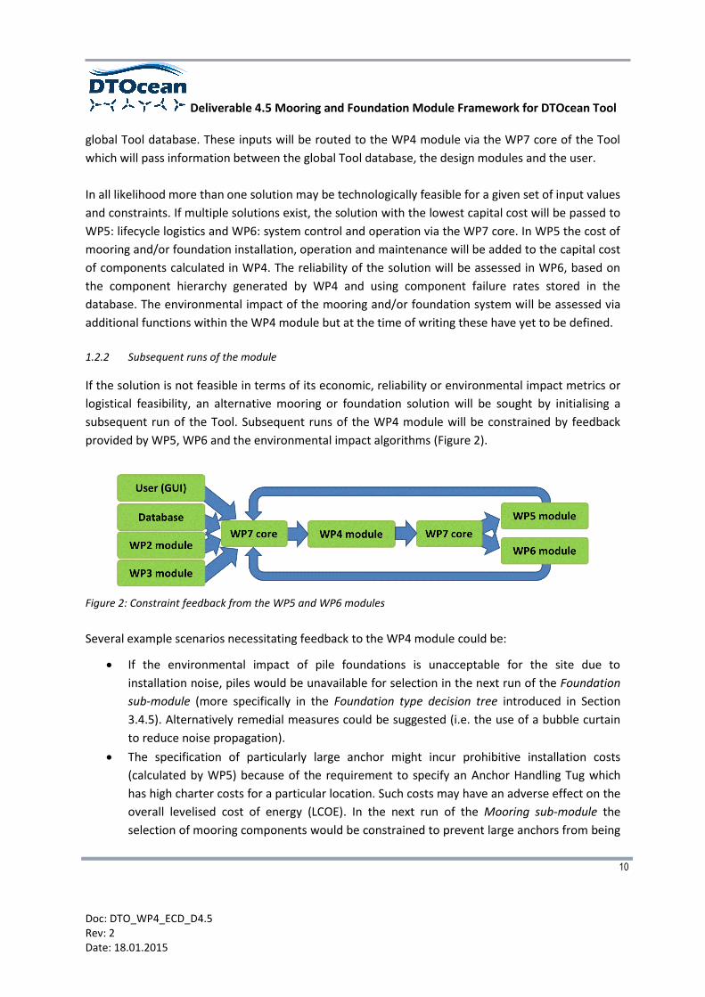
1.2.2 Subsequent runs of the module
If the solution is not feasible in terms of its economic, reliability or environmental impact metrics or
logistical feasibility, an alternative mooring or foundation solution will be sought by initialising a
subsequent run of the Tool. Subsequent runs of the WP4 module will be constrained by feedback
provided by WP5, WP6 and the environmental impact algorithms (Figure 2).
Figure 2: Constraint feedback from the WP5 and WP6 modules
Several example scenarios necessitating feedback to the WP4 module could be:
If the environmental impact of pile foundations is unacceptable for the site due to
installation noise, piles would be unavailable for selection in the next run of the Foundation
sub-module (more specifically in the Foundation type decision tree introduced in Section
3.4.5). Alternatively remedial measures could be suggested (i.e. the use of a bubble curtain
to reduce noise propagation).
The specification of particularly large anchor might incur prohibitive installation costs
(calculated by WP5) because of the requirement to specify an Anchor Handling Tug which
has high charter costs for a particular location. Such costs may have an adverse effect on the
overall levelised cost of energy (LCOE). In the next run of the Mooring sub-module the
selection of mooring components would be constrained to prevent large anchors from being
Deliverable 4.5 Mooring and Foundation Module Framework for DTOcean Tool
11
Doc: DTO_WP4_ECD_D4.5 Rev: 2 Date: 18.01.2015
selected and perhaps other technologies considered (an example of component selection is
given in Appendix A3).
If the reliability of the proposed system (as calculated by the WP6 module) is unacceptable
then similarly to the previous example a constraint would be set. Therefore only
components with a reliability level above a specified threshold would be available for
selection when the WP4 module is re-run1.
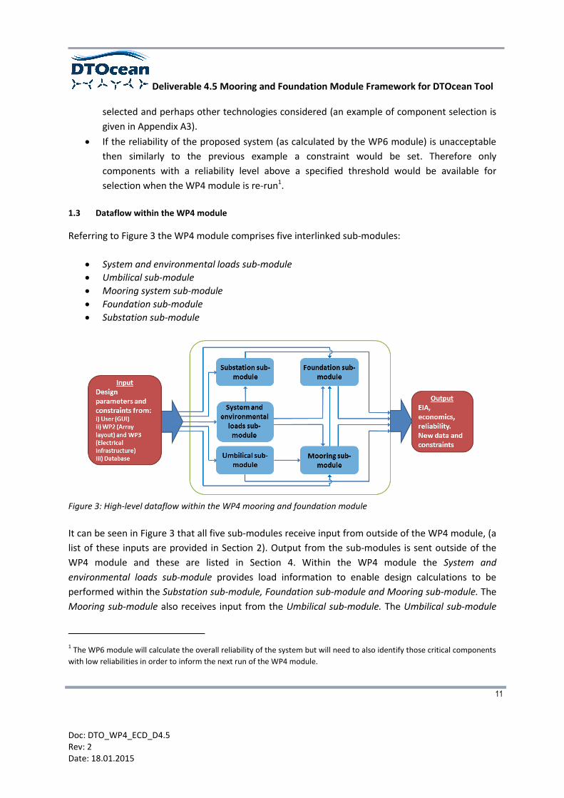
1.3 Dataflow within the WP4 module
Referring to Figure 3 the WP4 module comprises five interlinked sub-modules:
System and environmental loads sub-module
Umbilical sub-module
Mooring system sub-module
Foundation sub-module
Substation sub-module
Figure 3: High-level dataflow within the WP4 mooring and foundation module
It can be seen in Figure 3 that all five sub-modules receive input from outside of the WP4 module, (a
list of these inputs are provided in Section 2). Output from the sub-modules is sent outside of the
WP4 module and these are listed in Section 4. Within the WP4 module the System and
environmental loads sub-module provides load information to enable design calculations to be
performed within the Substation sub-module, Foundation sub-module and Mooring sub-module. The
Mooring sub-module also receives input from the Umbilical sub-module. The Umbilical sub-module
1 The WP6 module will calculate the overall reliability of the system but will need to also identify those critical components
with low reliabilities in order to inform the next run of the WP4 module.

Deliverable 4.5 Mooring and Foundation Module Framework for DTOcean Tool
12
Doc: DTO_WP4_ECD_D4.5 Rev: 2 Date: 18.01.2015
does not receive load information from the System and environmental loads sub-module, instead
loads are applied to the umbilical within the Mooring sub-module.
The calculation procedure invoked within the WP4 module will depend on whether the system is
floating or fixed. Floating systems require a mooring system and anchors to keep the system on
station (see Section 1.3.1). It can be seen in Figure 3 that dataflow occurs between the Mooring sub-
module and Foundation sub-module to allow suitable anchors to be selected. Fixed systems require a
foundation to provide a permanent connection between the system support structure and seafloor
(see Section 1.3.2). Both fixed and floating systems require an umbilical and the array will require a
substation. The type of system is therefore a specific input defined by the user and hence
determines which of the sub-modules within the WP4 module will be used.
A working directory (not shown in Appendix A1) will be used to pass information between the sub-
modules and temporarily store results.
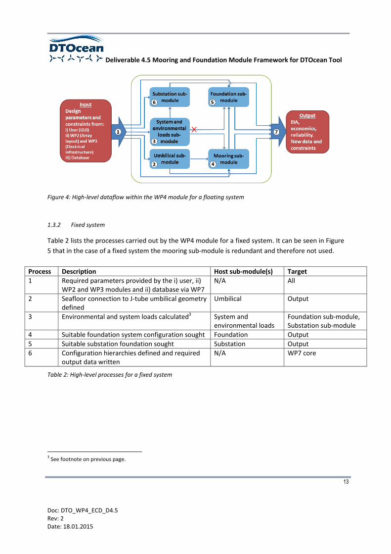
1.3.1 Floating system
Table 1 lists the processes carried out by the WP4 module for a floating system.
Process Description Host sub-module(s) Target
1 Required parameters provided by the i) user, ii) WP2 and WP3 modules and ii) database via WP7
N/A All
2 Lazy-wave umbilical geometry defined Umbilical Mooring sub-module, Output
3 Environmental and system loads calculated2 System and environmental loads
Mooring sub-module, Substation sub-module
4 Suitable mooring system configuration sought Mooring Foundation sub-module, Output
5 Suitable anchoring system sought Foundation Output
6 Suitable substation foundation sought Substation Output
7 Configuration hierarchies defined and required output data written
N/A WP7 core
Table 1:High-level processes for a floating system
2 Analysis of time-series to obtain extreme values will not be conducted within the WP4 module. Instead it will be
necessary for the user to provide extreme values for each environmental condition (see Section 3.4.2).
Deliverable 4.5 Mooring and Foundation Module Framework for DTOcean Tool
13
Doc: DTO_WP4_ECD_D4.5 Rev: 2 Date: 18.01.2015
Figure 4: High-level dataflow within the WP4 module for a floating system
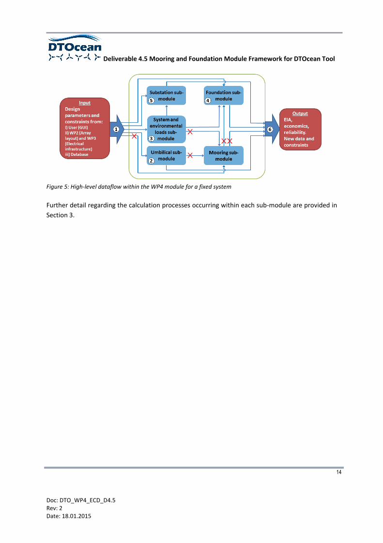
1.3.2 Fixed system
Table 2 lists the processes carried out by the WP4 module for a fixed system. It can be seen in Figure
5 that in the case of a fixed system the mooring sub-module is redundant and therefore not used.
Process Description Host sub-module(s) Target
1 Required parameters provided by the i) user, ii) WP2 and WP3 modules and ii) database via WP7
N/A All
2 Seafloor connection to J-tube umbilical geometry defined
Umbilical Output
3 Environmental and system loads calculated3 System and environmental loads
Foundation sub-module, Substation sub-module
4 Suitable foundation system configuration sought Foundation Output
5 Suitable substation foundation sought Substation Output
6 Configuration hierarchies defined and required output data written
N/A WP7 core
Table 2: High-level processes for a fixed system
3 See footnote on previous page.
Deliverable 4.5 Mooring and Foundation Module Framework for DTOcean Tool
14
Doc: DTO_WP4_ECD_D4.5 Rev: 2 Date: 18.01.2015
Figure 5: High-level dataflow within the WP4 module for a fixed system
Further detail regarding the calculation processes occurring within each sub-module are provided in
Section 3.

Deliverable 4.5 Mooring and Foundation Module Framework for DTOcean Tool
15
Doc: DTO_WP4_ECD_D4.5 Rev: 2 Date: 18.01.2015
2 WP4 MODULE INPUTS
The WP4 module inputs have been split into those which are site- and technology specific. Table 5
and Table 6 list the SI unit, scale type and origin (i.e. user, database or other WPs) of each
parameter. The parameters which are shared with other modules are identified by shaded cells and
modelling constraints are identified. By definition modelling constraints are those parameters which
restrict or limit the free design of mooring or foundation solutions, for example the soil type of the
site will preclude particular mooring or foundation types.
The DTOcean Tool will be packaged with a database (DB) populated with data relevant to each
module. Whilst the WP4 module will operate based on a minimal amount of ‘default’ data, the user
will be able to append their own data thus enabling the database to remain updated with
technological advances.
2.1 Data formats
Several different scale types are defined in this section to distinguish between different data types4.
Nominal parameters such as soil type must be specified across the site by the user (e.g. Table 3).
Cohesive (underconsolidated clays) Cohensionless (noncalcareous, dense)
Cohesive (normally consolidated at depth z) Cohensionless (noncalcareous, very dense)
Overconsolidated (consistencies: very firm, hard, very hard) Cohensionless (calcareous)
Cohensionless (noncalcareous, very loose to loose) Rock
Cohensionless (noncalcareous, medium dense)
Table 3: An example of a nominal parameter: soil type
Type Drained (effective) friction angle (deg)
Relative density (%) Buoyant unit weight (N/m^3)
Very loose to loose 28-30 0-50 45-55
Medium dense 30-36 50-70 55-65
Dense 35-42 70-85 60-70
Very dense 40-45 85-100 60-70
Table 4: Examples of numeric parameters specified as ranges (taken from [1])
Most parameters accessed from the database will be constant values (scale type: ratios). Where
linear or non-linear variability of a parameter exists, such as a geotechnical property, the parameter
will be specified range (e.g. Table 4). In the absence of suitable empirical relations, look-up tables
4 Further information can be found at http://onlinestatbook.com/2/introduction/levels_of_measurement.html

Deliverable 4.5 Mooring and Foundation Module Framework for DTOcean Tool
16
Doc: DTO_WP4_ECD_D4.5 Rev: 2 Date: 18.01.2015
will need to be specified in the database. An example of a non-linear parameter is given in Figure 6
for the design of pile foundations. In this case the coefficient of subgrade soil reaction is specified a
function of the maximum lateral deflection criteria (ymax/D based on maximum lateral deflection and
pile diameter) and relative soil density (Dr). This example would require a three-dimensional look-up
table. Because only a finite number of values can be specified in a look-up table an interpolation
scheme will have to be built into the module to approximate interim values.
Figure 6: Design values for the coefficient of subgrade soil reaction used in pile design (taken from [1])
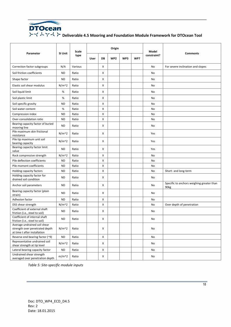
2.2 Site specific inputs
The Foundation sub-module requires a large number of site-specific inputs which are mainly seafloor
geotechnical or geophysical properties. At each grid point, the bathymetry, soil type and soil layers
(number and depth) will be defined. A complete list of geotechnical or geological parameters for
each grid point would require significant storage space within the database and instead it is
proposed that a default set of parameters for each soil type will be stored in the database which can
be modified by the user. The proposed hierarchy is illustrated in Figure 7.
Figure 7: Illustrative data hierarchy at each grid point

Deliverable 4.5 Mooring and Foundation Module Framework for DTOcean Tool
17
Doc: DTO_WP4_ECD_D4.5 Rev: 2 Date: 18.01.2015
Precise data may not be available to the user unless a detailed site survey has been conducted (i.e.
at the pre-consent stage only site bathymetry and seafloor surface soil type may be known). At the
very least the user will be expected to specify the bathymetry and assumed soil type at each grid
point5 with the latter accessed via a drop-down menu in the GUI. To ensure that the WP4 module
can operate with the minimum possible data soil homogeneity will be assumed if a single soil layer is
specified. If a coarse grid is specified then it is likely that complex and spatially dependent seafloor
features will be missed (i.e. [2]). Further work is required to determine how spatial variability will be
adequately addressed within the WP4 module (i.e. the suitability of assuming uniform properties
over the entire or large portions of the domain).
Parameter SI
Unit6 Scale type
Origin Model
constraint? Comments
User DB WP2 WP3 WP7
Soil type N/A Nominal X Yes e.g. unconsolidated clay
Soil depth and layering m Ratio X Yes Identified soil layers at each grid point
Bathymetry m Ratio X Yes (x,y,z) using global coordinate system
Water level m Ratio X Yes Maximum and minimum water levels
Surface current flow velocity m/s Ratio X No Maximum (return period dependent7)
Current flow direction deg Ratio X No Associated with max current flow velocity
Significant wave height m Ratio X No Maximum (return period dependent)
Peak wave period s Ratio X No Associated with significant wave height
Zero up crossing wave period s Ratio X No Associated with significant wave height
Spectrum peakedness ND Ratio X No To alter JONSWAP spectrum
Predominant wave direction deg Ratio X No Associated with significant wave height
Wind gust speed m/s Ratio X No Maximum (return period dependent)
Predominant wind direction deg Ratio X No Associated with max wind gust speed
Effective drained cohesion N/m^2 Ratio X No
Undrained soil friction angle deg Ratio X No
Drained soil friction angle deg Ratio X No
Relative soil density % Ratio X No
Buoyant unit weight of soil N/m^3 Ratio X No
Undrained soil shear strengths N/m^2 Ratio X No
5 A GIS mapping approach could be adopted and if limited site data is available soil types could be inferred from open
source data (i.e. http://mapapps2.bgs.ac.uk/geoindex_offshore/home.html)
6 ND = non-dimensional
7 Further information regarding the appropriate return periods which will be used for water level, wind, current and waves
can be found in Section 3.1.1
Deliverable 4.5 Mooring and Foundation Module Framework for DTOcean Tool
18
Doc: DTO_WP4_ECD_D4.5 Rev: 2 Date: 18.01.2015
Parameter SI Unit Scale type
Origin Model
constraint? Comments
User DB WP2 WP3 WP7
Correction factor subgroups N/A Various X No For severe inclination and slopes
Soil friction coefficients ND Ratio X No
Shape factor ND Ratio X No
Elastic soil shear modulus N/m^2 Ratio X No
Soil liquid limit % Ratio X No
Soil plastic limit % Ratio X No
Soil specific gravity ND Ratio X No
Soil water content % Ratio X No
Compression index ND Ratio X No
Over-consolidation ratio ND Ratio X No
Bearing capacity factor of buried mooring line
ND Ratio X No
Pile maximum skin frictional resistance
N/m^2 Ratio X Yes
Pile tip maximum unit soil bearing capacity
N/m^2 Ratio X Yes
Bearing capacity factor limit value
ND Ratio X Yes
Rock compressive strength N/m^2 Ratio X No
Pile deflection coefficients ND Ratio X No
Pile moment coefficients ND Ratio X No
Holding capacity factors ND Ratio X No Short- and long-term
Holding capacity factor for drained soil condition
ND Ratio X No
Anchor soil parameters ND Ratio X No Specific to anchors weighing greater than 90kg
Bearing capacity factor (plain strain)
ND Ratio X No
Adhesion factor ND Ratio X No
DSS shear strength N/m^2 Ratio X No Over depth of penetration
Coefficient of external shaft friction (i.e., steel to soil)
ND Ratio X No
Coefficient of internal shaft friction (i.e., steel to soil)
ND Ratio X No
Average undrained soil shear strength over penetrated depth at time t after installation
N/m^2 Ratio X No
Reverse end bearing factor (~9) ND Ratio X No
Representative undrained soil shear strength at tip level
N/m^2 Ratio X No
Lateral bearing capacity factor ND Ratio X No
Undrained shear strength averaged over penetration depth
m/m^2 Ratio X No
Table 5: Site-specific module inputs

Deliverable 4.5 Mooring and Foundation Module Framework for DTOcean Tool
19
Doc: DTO_WP4_ECD_D4.5 Rev: 2 Date: 18.01.2015
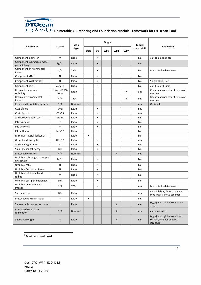
2.3 Technology specific inputs
Technology specific inputs to WP4 are listed in Table 6. These are either supplied by the user or
originate from WP2 (array layout) or WP3 (electrical infrastructure).
Parameter SI Unit Scale type
Origin Model
constraint? Comments
User DB WP2 WP3 WP7
Device ID number N/A Nominal X No Identification number of each device
Type of device N/A Nominal X Yes e.g. tidal floating
Depth variation permitted N/A Nominal X Yes e.g. yes/no
System mass kg Ratio X No Includes support structure if relevant
System centre of gravity m Ratio X No (x,y,z) w.r.t. system origin
System displaced volume m^3 Ratio X No Includes support structure if relevant
System height m Ratio X No Includes support structure if relevant
Fairlead locations m Ratio X Yes (x,y,z) for each fairlead w.r.t. system origin
Prescribed foundation locations
m Ratio X Yes (x,y,z) for each foundation point w.r.t. system origin
Umbilical connection point m Ratio X Yes (x,y,z) w.r.t. system origin
Wet frontal area m^2 Ratio X No
Dry frontal area m^2 Ratio X No
Rotor swept area m^2 Ratio X No
Thrust coefficient ND Ratio X X No
Thrust curve N(m/s) Ratio X X No
Hub height m Ratio X No Specified w.r.t. system origin
Orientation angle deg Ratio X No Specified w.r.t. grid north
System origin m Ratio X Yes (x,y,z) w.r.t. global coordinate system
Drag coefficients ND Ratio X No
Structure profile N/A Nominal X No e.g. cylindrical, rectangular, elliptical
Inertia coefficients ND Ratio X No
First-order wave load RAOs8 F(T) Ratio X No Wave period-dependent parameter
Radiation damping B(T) Ratio X No Wave period-dependent parameter
Added mass A(T) Ratio X No Wave period-dependent parameter
Prescribed mooring system N/A Nominal X Yes Optional
Maximum displacement amplitudes
N Ratio X Yes For each mode of motion
8 Response amplitude operators
Deliverable 4.5 Mooring and Foundation Module Framework for DTOcean Tool
20
Doc: DTO_WP4_ECD_D4.5 Rev: 2 Date: 18.01.2015
Parameter SI Unit Scale type
Origin Model
constraint? Comments
User DB WP2 WP3 WP7
Component diameter m Ratio X No e.g. chain, rope etc
Component submerged mass per unit length
kg/m Ratio X No
Component environmental impact
N/A TBD X No Metric to be determined
Component MBL9 N Ratio X No
Component axial stiffness N Ratio X No Single value used
Component cost Various Ratio X No e.g. €/m or €/unit
Required component reliability
Failures/10^6 hours
Ratio X Yes Constraint used after first run of module
Required environmental impact
N/A TBD X Yes Constraint used after first run of module
Prescribed foundation system N/A Nominal X Yes Optional
Cost of steel €/kg Ratio X Yes
Cost of grout €/m^3 Ratio X Yes
Anchor/foundation cost €/unit Ratio X Yes
Pile diameter m Ratio X No
Pile thickness m Ratio X No
Pile stiffness N.m^2 Ratio X No
Maximum lateral deflection m Ratio X No
Grout bond strength N/m^2 Ratio X Yes
Anchor weight in air kg Ratio X No
Small anchor efficiency ND Ratio X No
Prescribed umbilical N/A Nominal X Yes
Umbilical submerged mass per unit length
kg/m Ratio X No
Umbilical MBL N Ratio X No
Umbilical flexural stiffness N Ratio X No
Umbilical minimum bend radius
m Ratio X No
Umbilical cost per unit length €/m Ratio X No
Umbilical environmental impact
N/A TBD X Yes Metric to be determined
Safety factors ND Ratio X Yes For umbilical, foundation and moorings. Various schemes
Prescribed footprint radius m Ratio X Yes
Subsea cable connection point m Ratio X Yes (x,y,z) w.r.t. global coordinate system
Prescribed substation foundation
N/A Nominal X Yes e.g. monopile
Substation origin m Ratio X No (x,y,z) w.r.t. global coordinate system, includes support structure
9 Minimum break load

Deliverable 4.5 Mooring and Foundation Module Framework for DTOcean Tool
21
Doc: DTO_WP4_ECD_D4.5 Rev: 2 Date: 18.01.2015
Parameter SI Unit Scale type
Origin Model
constraint? Comments
User DB WP2 WP3 WP7
Substation mass kg Ratio X No Includes support structure
Substation centre of gravity m Ratio X No (x,y,z) w.r.t. substation origin
Substation wet frontal area m^2 Ratio X No Includes support structure
Substation dry frontal area m^2 Ratio X No Includes support structure
Table 6: Technology-specific module inputs (parameters shared with other modules are indicated by shading)

Deliverable 4.5 Mooring and Foundation Module Framework for DTOcean Tool
22
Doc: DTO_WP4_ECD_D4.5 Rev: 2 Date: 18.01.2015
3 OVERVIEW OF THE PROPOSED ANALYSIS PROCEDURE
Although the DTOcean tool is a decision tool, each design needs to be assessed in order to make an
informed decision. Design principles and formulae for moorings and foundations of marine
structures are treated in a wide variety of design standards. These are discussed in the next
subsection.
3.1 Design standards
Referring to the module flowchart in the Appendix A1, the analysis procedure will follow the design
approaches adopted in widely used guidance documents, including (but not limited to) IEC 62600-10
[3], DNV-OS-E301 [4], DNV-RP-C205 [5], DNV Classification Note 30.4 [6], DNV-OS-J103 [7], DNV-OS-
J101 [8], DNV-RP-J301 [9], API-2A-WSD [10], the Handbook for Marine Geotechnical Engineering [1]
as well as various published texts (i.e. [11, 12, 13]).
3.1.1 Limit States
The general design approach for a marine structure and its mooring or foundation consists of
verification of a number of limit states or failure modes, i.e. a condition beyond which a structure or
component no longer satisfies the design requirements. The following limit states are considered in
Section 2 of DNV-OS-J101 [8] for offshore wind turbines:
Ultimate limit states (ULS) corresponds to the maximum load-carrying resistance
Fatigue limit states (FLS) corresponds to failure due to the effect of cyclic loading
Accidental limit states (ALS) corresponds to damage to components due to an accidental event or operational failure
Serviceability limit states (SLS) corresponds to tolerance criteria applicable to normal use.
Examples of limit states within each category are:
Ultimate limit states (ULS) o ‘loss of structural resistance (excessive yielding and buckling) o failure of components due to brittle fracture o loss of static equilibrium of the structure, or of a part of the structure, considered as
a rigid body, e.g. overturning or capsizing o failure of critical components of the structure caused by exceeding the ultimate
resistance (which in some cases is reduced due to repetitive loading) or the ultimate deformation of the components
o transformation of the structure into a mechanism (collapse or excessive deformation)’.

Deliverable 4.5 Mooring and Foundation Module Framework for DTOcean Tool
23
Doc: DTO_WP4_ECD_D4.5 Rev: 2 Date: 18.01.2015
Fatigue limit states (FLS) o ‘cumulative damage due to repeated loads’.
Accidental limit states (ALS) o ‘accidental conditions such as structural damage caused by accidental loads and
resistance of damaged structures’.
Serviceability limit states (SLS) o ‘deflections that may alter the effect of the acting forces o deformations that may change the distribution of loads between supported rigid objects
and the supporting structure o excessive vibrations producing discomfort or affecting non-structural components o motions that exceed the limitation of equipment o differential settlements of foundations soils causing intolerable tilt of the wind turbine o temperature-induced deformations’.
Safety factors are applied on top of the rated strengths or resistances of components (i.e. such as
minimum break load; MBL) to provide an adequate margin of safety. In the DNV approach safety
factors are specified in the context of safety level (i.e. [8, 7, 14]) or consequence class [4] to reflect
the effect of failure (however the latter reference has been developed for the oil and gas industry
where the consequence of failure is potentially much greater). Of more relevance to MRE devices
are the safety levels specified in DNV-OSS-213 [14]:
‘Safety Level Low – where failure implies low risk of human injury and minor environmental and economic consequences.
Safety Level Normal – for temporary conditions where failure implies risk of human injury, significant environmental pollution or high economic, asset damage or political consequences. This level normally aims for a risk of less than 10-4 per year of a major single accident, which corresponds to a major incident happening on average less than once every 10,000 installation years. This level equates to the experience level from major representative industries and activities.
Safety Level High – for operating conditions where failure implies high risk of human injury, significant environmental pollution or very high economic or political consequences’.
3.1.2 Foundation design
DNV-OS-J101 [8] utilises the partial safety factor method, in which load and resistance factors (i.e.
the safety factors) are applied to characteristic values of the governing variables, in order to obtain
the design load effect (a function of individual design loads) and design resistance. The governing
variables are loads acting on the structure or load effects in the structure and the geotechnical
resistance of the surrounding soil or rock. The characteristic values mentioned above are typically
chosen as specific quantiles in probability distributions. The safety factors are different for each of
the limit states, but generally speaking safety factors applied to loads result in an ‘exaggeration’ of

Deliverable 4.5 Mooring and Foundation Module Framework for DTOcean Tool
24
Doc: DTO_WP4_ECD_D4.5 Rev: 2 Date: 18.01.2015
the applicable loads, while safety factors for resistance ‘weaken’ the material/components. The
Handbook for Marine Geotechnical Engineering [1] proposes a similar approach, however only
applying safety factors to the loads (these therefore include the uncertainty on the
material/structure properties). If the necessary soil data is accurately known (from in-situ testing or
laboratory testing of core samples), a safety factor of 1.5 to 2.0 is recommended10. If soil properties
are not accurately known, a higher safety factor of 2.0 to 3.0 should be used.
A particular aspect for offshore wind turbine foundation design (see Section 10 of DNV-OS-J101 [8])
is that failure due to effect of cyclic loading is treated as an ULS, or alternatively as an ALS, using
partial load and material factors as defined for these limit state categories. So no FLS is used for
foundation design. This emphasizes the importance of cyclic loading analysis in the design of
offshore wind turbines.
The design formulae mentioned in each of these standards are very similar and determine how to
calculate or numerically model the interaction between the combined design load effects and design
resistance for each of the failure modes.
However, not all standards are clear on how to determine the characteristic values linked to the
design loads and design resistance for each of the limit states. For example, the Handbook for
Marine Geotechnical Engineering [1] mentions for the design of foundation piles that maximum load
or load combinations at the seafloor surface are to be determined from a separate analysis of what
is attached to the pile. Sections 4 and 5 of DNV-OS-J101 [8] on the other hand clearly explain the
loads, load effects and load and resistance factors used for the design of offshore wind turbine
structures and their foundations. Furthermore, formulae are presented that link site conditions to
the corresponding loads (additional info can be found in DNV-RP-C205 [5]). Loads are separated into
permanent loads (e.g. mass of the structure), variable functional loads (e.g. personnel, ship impacts
from service vessels, loads associated with installation operations, etc), environmental loads,
abnormal wind turbine loads and deformation loads (e.g. temperature loads, settlements). The
environmental loads are further split up in wind loads (and indirect wind loads, e.g. centrifugal
force), wave loads, ice loads, water level loads, earthquake loads, marine growth, scour and
transportation and installation loads. In reality, combinations of these environmental loads will
occur and hence a separate subsection explains how to deal with these situations. For ULS design
(similar reasoning for other limit states), the combined load effect whose return period is 50 years
(i.e. with associated probability of occurrence of 0.02) is used. Based on DNV-OS-J101 [8] the
following three load combinations are proposed to define the characteristic value of the
environmental load effect for ULS in an ice-free offshore wind location:
10
Specified for piles, shallow foundations and gravity anchors.
Deliverable 4.5 Mooring and Foundation Module Framework for DTOcean Tool
25
Doc: DTO_WP4_ECD_D4.5 Rev: 2 Date: 18.01.2015
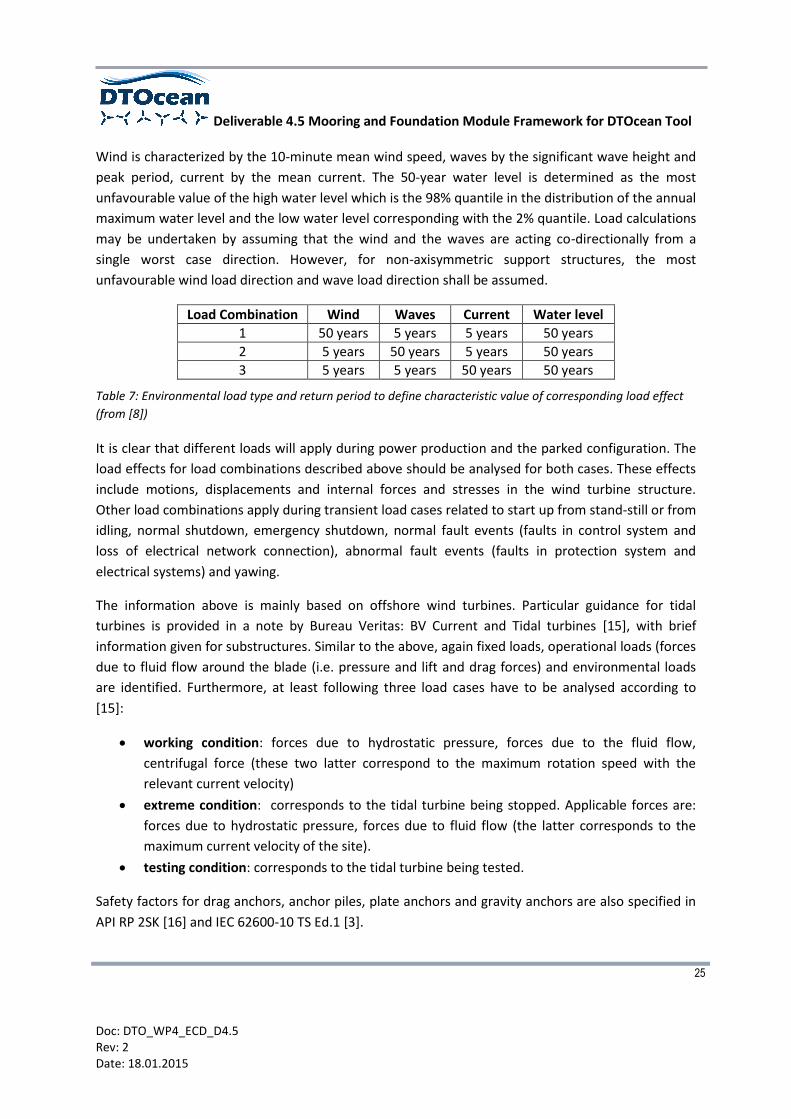
Wind is characterized by the 10-minute mean wind speed, waves by the significant wave height and
peak period, current by the mean current. The 50-year water level is determined as the most
unfavourable value of the high water level which is the 98% quantile in the distribution of the annual
maximum water level and the low water level corresponding with the 2% quantile. Load calculations
may be undertaken by assuming that the wind and the waves are acting co-directionally from a
single worst case direction. However, for non-axisymmetric support structures, the most
unfavourable wind load direction and wave load direction shall be assumed.
Load Combination Wind Waves Current Water level
1 50 years 5 years 5 years 50 years
2 5 years 50 years 5 years 50 years
3 5 years 5 years 50 years 50 years
Table 7: Environmental load type and return period to define characteristic value of corresponding load effect
(from [8])
It is clear that different loads will apply during power production and the parked configuration. The
load effects for load combinations described above should be analysed for both cases. These effects
include motions, displacements and internal forces and stresses in the wind turbine structure.
Other load combinations apply during transient load cases related to start up from stand-still or from
idling, normal shutdown, emergency shutdown, normal fault events (faults in control system and
loss of electrical network connection), abnormal fault events (faults in protection system and
electrical systems) and yawing.
The information above is mainly based on offshore wind turbines. Particular guidance for tidal
turbines is provided in a note by Bureau Veritas: BV Current and Tidal turbines [15], with brief
information given for substructures. Similar to the above, again fixed loads, operational loads (forces
due to fluid flow around the blade (i.e. pressure and lift and drag forces) and environmental loads
are identified. Furthermore, at least following three load cases have to be analysed according to
[15]:
working condition: forces due to hydrostatic pressure, forces due to the fluid flow,
centrifugal force (these two latter correspond to the maximum rotation speed with the
relevant current velocity)
extreme condition: corresponds to the tidal turbine being stopped. Applicable forces are:
forces due to hydrostatic pressure, forces due to fluid flow (the latter corresponds to the
maximum current velocity of the site).
testing condition: corresponds to the tidal turbine being tested.
Safety factors for drag anchors, anchor piles, plate anchors and gravity anchors are also specified in
API RP 2SK [16] and IEC 62600-10 TS Ed.1 [3].
Deliverable 4.5 Mooring and Foundation Module Framework for DTOcean Tool
26
Doc: DTO_WP4_ECD_D4.5 Rev: 2 Date: 18.01.2015
3.1.3 Mooring system design
Various guidance documents exist for the design and certification of offshore mooring systems
including DNV-OS-E301 [4], IEC 62600-10 [3], BV NR 493 DT R02 E [17], API RP 2SK [16] and
ISO19901-7:2013 [18]. Additionally, DNV-OSS-213 [14] is focused on wave energy converters (WECs)
and tidal energy converters (TECs) but in terms of mooring system design the guidance document
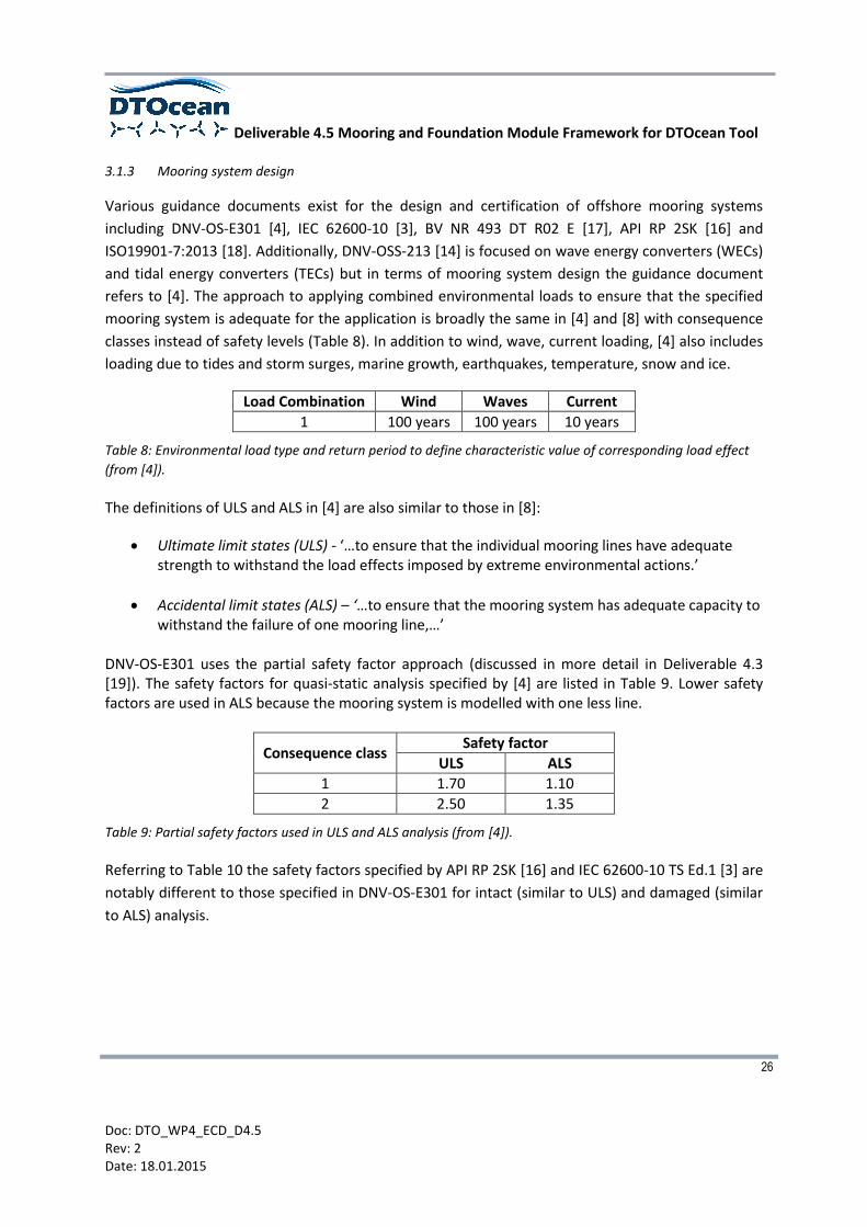
refers to [4]. The approach to applying combined environmental loads to ensure that the specified
mooring system is adequate for the application is broadly the same in [4] and [8] with consequence
classes instead of safety levels (Table 8). In addition to wind, wave, current loading, [4] also includes
loading due to tides and storm surges, marine growth, earthquakes, temperature, snow and ice.
Load Combination Wind Waves Current
1 100 years 100 years 10 years
Table 8: Environmental load type and return period to define characteristic value of corresponding load effect
(from [4]).
The definitions of ULS and ALS in [4] are also similar to those in [8]:
Ultimate limit states (ULS) - ‘…to ensure that the individual mooring lines have adequate strength to withstand the load effects imposed by extreme environmental actions.’
Accidental limit states (ALS) – ‘…to ensure that the mooring system has adequate capacity to withstand the failure of one mooring line,…’
DNV-OS-E301 uses the partial safety factor approach (discussed in more detail in Deliverable 4.3 [19]). The safety factors for quasi-static analysis specified by [4] are listed in Table 9. Lower safety factors are used in ALS because the mooring system is modelled with one less line.
Consequence class Safety factor
ULS ALS
1 1.70 1.10
2 2.50 1.35
Table 9: Partial safety factors used in ULS and ALS analysis (from [4]).
Referring to Table 10 the safety factors specified by API RP 2SK [16] and IEC 62600-10 TS Ed.1 [3] are
notably different to those specified in DNV-OS-E301 for intact (similar to ULS) and damaged (similar
to ALS) analysis.

Deliverable 4.5 Mooring and Foundation Module Framework for DTOcean Tool
27
Doc: DTO_WP4_ECD_D4.5 Rev: 2 Date: 18.01.2015
Intact Damaged
Tension limit (%MBS) 50 70
Equipment safety factor 2.0 1.43
Table 10: Tension limits and equipment safety factors used in Intact and Damaged state analysis (from [16]).
3.2 Applicability of existing standards to MRE devices and the DTOcean Design Tool
Simplified design approaches will be used within the WP4 module so that the simulations are
completed in an acceptable time frame11. A comprise between the run time of the decision tool and
the level of solution complexity will therefore be sought. It is important that the applied
methodologies should still be sufficiently accurate12 so that a proper (realistic) decision can be made.
It is easy to understand that the design principle for offshore wind moorings or foundations will also
be very similar to those for WECs and TECs. The general approach for tidal turbines will hence be
identical to the one for offshore wind turbines. Specifically, it is likely that the effect of tidal currents
and waves will be more significant for WECs and TECs than for wind turbines and wind will be less of
a matter for the design of the moorings or foundations, unless surface piercing support structures
are used (e.g. a substation positioned above the sea surface). This is an important consideration
when calculating the design forces and moments at the moorings or foundations, however the
design process itself is assumed to be identical.
It appears from the design standards discussed above that the potential failure of the MRE mooring
or foundation needs to be checked for several limit states, load combinations and operational
conditions. This approach is considered not to be realistic for the DTOcean Tool at present. A
number of assumptions will be made in order to restrict the number of load cases to be considered
for design. Firstly, only static/quasi-static analysis will be carried out within this project in order not
to overload calculations within Version 1 of the DTOcean Tool. It is acknowledged that
dynamic/cyclic loading is also important for MRE devices (at least as important as for offshore wind
turbines), but this case will not be considered in Version 1 of the Tool. Only load cases for ULS and
ALS will be considered, see the System and environmental loads sub-module introduced in Section
3.4.2.
Secondly with the exception of pile foundations, the module will not carry out a structural analysis of
the foundations or anchors; these components are considered to be rigid. In the first instance the
module will therefore only consider the interaction between the foundation or anchor and soil for
lateral and axial load analysis.
11
The DTOcean Tool will be designed to run on an off-the-shelf laptop using Windows as an operating system. The target
run time of the WP4 module will be in the order of minutes
12 The required level of accuracy will be defined as the module is further developed
Deliverable 4.5 Mooring and Foundation Module Framework for DTOcean Tool
28
Doc: DTO_WP4_ECD_D4.5 Rev: 2 Date: 18.01.2015
In terms of design formulae for the different types of foundations, the straightforward approach for
foundation design mentioned in the Handbook for Marine Geotechnical Engineering [1] will be used
for the DTOcean project. It follows an iterative or trial and-error process. The process starts with an
estimation of reasonable or “convenient” foundation dimensions, and then an analysis is made to
predict performance. If the proposed foundation is found to be inadequate or to be excessively
overdesigned13, the dimensions are changed and the analysis process is repeated. In some cases the
selected foundation for the given soil conditions may be found impractical or too costly. Other
foundation types must then be considered. It should be noted that [1] partially does carry out
structural analysis, i.e. steel stress analysis for the case of piles. It is also important to note that the
applicability of the formulae from [1] that will be used within the DTOcean Tool is limited with
regards to seafloor heterogeneity and this will be investigated as part of the validation process of
the WP4 module.
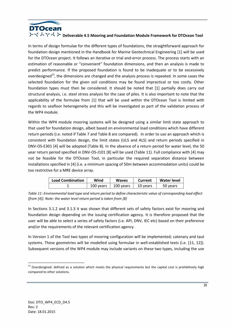
Within the WP4 module mooring systems will be designed using a similar limit state approach to
that used for foundation design, albeit based on environmental load conditions which have different
return periods (i.e. noted if Table 7 and Table 8 are compared). In order to use an approach which is
consistent with foundation design, the limit states (ULS and ALS) and return periods specified in
DNV-OS-E301 [4] will be adopted (Table 8). In the absence of a return period for water level, the 50
year return period specified in DNV-OS-J101 [8] will be used (Table 11). Full compliance with [4] may
not be feasible for the DTOcean Tool, in particular the required separation distance between
installations specified in [4] (i.e. a minimum spacing of 50m between accommodation units) could be
too restrictive for a MRE device array.
Load Combination Wind Waves Current Water level
1 100 years 100 years 10 years 50 years
Table 11: Environmental load type and return period to define characteristic value of corresponding load effect
(from [4]). Note: the water level return period is taken from [8]
In Sections 3.1.2 and 3.1.3 it was shown that different sets of safety factors exist for mooring and
foundation design depending on the issuing certification agency. It is therefore proposed that the
user will be able to select a series of safety factors (i.e. API, DNV, IEC etc) based on their preference
and/or the requirements of the relevant certification agency.
In Version 1 of the Tool two types of mooring configuration will be implemented; catenary and taut
systems. These geometries will be modelled using formulae in well-established texts (i.e. [11, 12]).
Subsequent versions of the WP4 module may include variants on these two types, including the use
13
Overdesigned: defined as a solution which meets the physical requirements but the capital cost is prohibitively high
compared to other solutions.
Deliverable 4.5 Mooring and Foundation Module Framework for DTOcean Tool
29
Doc: DTO_WP4_ECD_D4.5 Rev: 2 Date: 18.01.2015
of floats and clump weights (for an overview of alternative systems, the reader is directed to
Deliverable 4.1 [20]).
The proposed analysis procedure based on the assumptions above is presented in Section 3.4 below.
The different sub-modules of the WP4 module associated with the design of moorings and
foundations of MRE devices are presented using a number of flowcharts. The conventions used for
these flowcharts are described in Section 3.3.
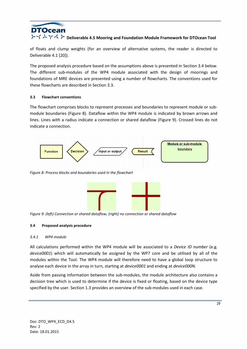
3.3 Flowchart conventions
The flowchart comprises blocks to represent processes and boundaries to represent module or sub-
module boundaries (Figure 8). Dataflow within the WP4 module is indicated by brown arrows and
lines. Lines with a radius indicate a connection or shared dataflow (Figure 9). Crossed lines do not
indicate a connection.
Figure 8: Process blocks and boundaries used in the flowchart
Figure 9: (left) Connection or shared dataflow, (right) no connection or shared dataflow
3.4 Proposed analysis procedure
3.4.1 WP4 module
All calculations performed within the WP4 module will be associated to a Device ID number (e.g.
device0001) which will automatically be assigned by the WP7 core and be utilised by all of the
modules within the Tool. The WP4 module will therefore need to have a global loop structure to
analyse each device in the array in turn, starting at device0001 and ending at device000N.
Aside from passing information between the sub-modules, the module architecture also contains a
decision tree which is used to determine if the device is fixed or floating, based on the device type
specified by the user. Section 1.3 provides an overview of the sub-modules used in each case.
Deliverable 4.5 Mooring and Foundation Module Framework for DTOcean Tool
30
Doc: DTO_WP4_ECD_D4.5 Rev: 2 Date: 18.01.2015
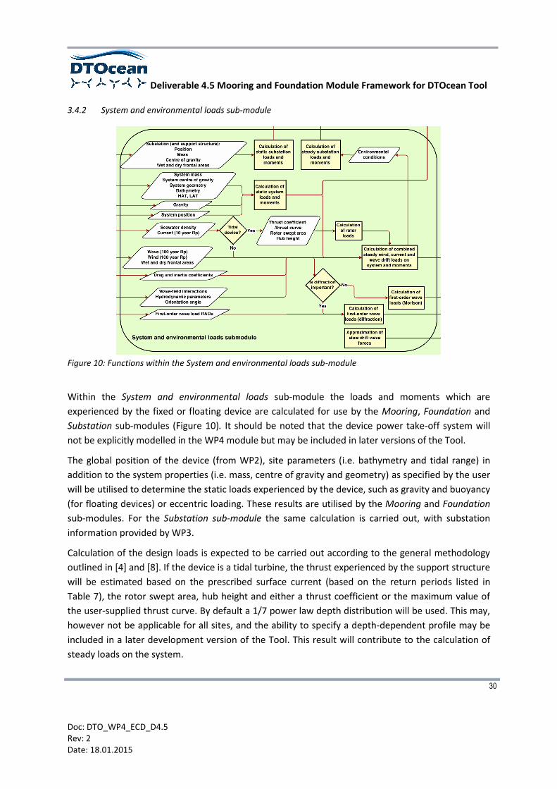
3.4.2 System and environmental loads sub-module
Figure 10: Functions within the System and environmental loads sub-module
Within the System and environmental loads sub-module the loads and moments which are
experienced by the fixed or floating device are calculated for use by the Mooring, Foundation and
Substation sub-modules (Figure 10). It should be noted that the device power take-off system will
not be explicitly modelled in the WP4 module but may be included in later versions of the Tool.
The global position of the device (from WP2), site parameters (i.e. bathymetry and tidal range) in
addition to the system properties (i.e. mass, centre of gravity and geometry) as specified by the user
will be utilised to determine the static loads experienced by the device, such as gravity and buoyancy
(for floating devices) or eccentric loading. These results are utilised by the Mooring and Foundation
sub-modules. For the Substation sub-module the same calculation is carried out, with substation
information provided by WP3.
Calculation of the design loads is expected to be carried out according to the general methodology
outlined in [4] and [8]. If the device is a tidal turbine, the thrust experienced by the support structure
will be estimated based on the prescribed surface current (based on the return periods listed in
Table 7), the rotor swept area, hub height and either a thrust coefficient or the maximum value of
the user-supplied thrust curve. By default a 1/7 power law depth distribution will be used. This may,
however not be applicable for all sites, and the ability to specify a depth-dependent profile may be
included in a later development version of the Tool. This result will contribute to the calculation of
steady loads on the system.

Deliverable 4.5 Mooring and Foundation Module Framework for DTOcean Tool
31
Doc: DTO_WP4_ECD_D4.5 Rev: 2 Date: 18.01.2015
The calculated static loads are utilised by the Calculation of combined steady wind, current and wave
drift loads on system and moments function. In this function, the specified wind and wave
conditions14 in addition to current (with return periods defined in Table 7 and Table 8) are used to
estimate the steady loads on the system. These calculations utilise drag and inertia coefficients
stored in the database15 as well as the user-specified wet and dry frontal areas. For floating devices,
first-order wave load RAOs (as calculated by WP2) will be used to estimate mean drift loads.
Figure 11: The relationship between wave parameters, structure size and wave forces (taken from [11])
The next stage is the Calculation of first-order wave loads function, which for floating devices, will be
used by the Mooring sub-module to estimate oscillations of the device about the mean offset
position. The approach used to calculate wave loads on the device or structure will depend on
whether diffraction is important, which will be judged by the size of the structure in relation to the
incident wave parameters and water depth at the device location (e.g. Figure 11). If diffraction
should be considered, hydrodynamic parameters calculated by WP2, including added mass, radiation
damping and first-order wave load RAOs will be used. If the diffraction regime is not relevant, wave
loads on the structure are estimated using the Morison equation and the aforementioned drag and
inertia coefficients.
Slow drift wave forces will also be estimated, probably using the approach given in Chakrabarti [12].
14
Wave load combinations of significant wave height, wave period (peak or zero up-crossing) and direction along the
relevant return period contour will be considered, necessitating several iterations of this function.
15 Drag and inertia coefficients for common geometries will be stored in the database. It will be up to the user to select
which geometry most closely matches the device in question (e.g. a fixed tidal turbine structure could crudely be
represented by cylindrical members).

Deliverable 4.5 Mooring and Foundation Module Framework for DTOcean Tool
32
Doc: DTO_WP4_ECD_D4.5 Rev: 2 Date: 18.01.2015
3.4.3 Umbilical sub-module
A flowchart showing the main functions of the Umbilical sub-module is provided in Figure 12. Based
on the location of the subsea cable (as specified by WP3) and required umbilical properties and the
bathymetry of the site (retrieved from the database) the umbilical geometry will be defined. The
equilibrium geometry of the umbilical will be determined iteratively. Two options are available
depending on whether the device is fixed (a ‘hang-off’-type geometry from the subsea cable up to
the J-tube) [9] or floating (‘Lazy-wave’ geometry) [21].
Figure 12: Functions within the Umbilical sub-module
The calculated length of the umbilical will then be sent to WP3 (via the WP7 core) to determine its
capital cost and any power losses. The calculated geometry and umbilical constraints (minimum
break load and minimum bend radius) will be used by the Mooring Foundation sub-modules.
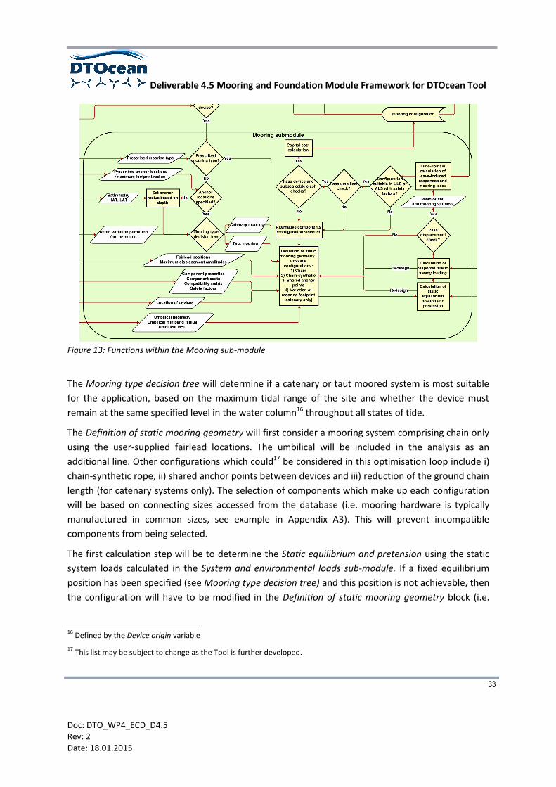
3.4.4 Mooring sub-module
If the device is floating, mooring systems with anchors will be considered. The user may have a
particular mooring system type in mind, perhaps from laboratory experiments or field trials of a
single device. If a type has been specified by the user, the Mooring type decision tree will be skipped.
If the location of the anchors or a maximum footprint radius has been specified by the user then
these values will be used in the definition of the mooring system geometry. Alternatively an anchor
radius will be set by the Mooring sub-module using a relationship between the mooring line length
and water depth (i.e. Fitzgerald et al. considered mooring line lengths ranging from 3-8x the water
depth in [22]), based on the supplied site bathymetry as well as maximum and minimum water level
values.
Deliverable 4.5 Mooring and Foundation Module Framework for DTOcean Tool
33
Doc: DTO_WP4_ECD_D4.5 Rev: 2 Date: 18.01.2015
Figure 13: Functions within the Mooring sub-module
The Mooring type decision tree will determine if a catenary or taut moored system is most suitable
for the application, based on the maximum tidal range of the site and whether the device must
remain at the same specified level in the water column16 throughout all states of tide.
The Definition of static mooring geometry will first consider a mooring system comprising chain only
using the user-supplied fairlead locations. The umbilical will be included in the analysis as an
additional line. Other configurations which could17 be considered in this optimisation loop include i)
chain-synthetic rope, ii) shared anchor points between devices and iii) reduction of the ground chain
length (for catenary systems only). The selection of components which make up each configuration
will be based on connecting sizes accessed from the database (i.e. mooring hardware is typically
manufactured in common sizes, see example in Appendix A3). This will prevent incompatible
components from being selected.
The first calculation step will be to determine the Static equilibrium and pretension using the static
system loads calculated in the System and environmental loads sub-module. If a fixed equilibrium
position has been specified (see Mooring type decision tree) and this position is not achievable, then
the configuration will have to be modified in the Definition of static mooring geometry block (i.e.
16
Defined by the Device origin variable
17 This list may be subject to change as the Tool is further developed.
Deliverable 4.5 Mooring and Foundation Module Framework for DTOcean Tool
34
Doc: DTO_WP4_ECD_D4.5 Rev: 2 Date: 18.01.2015
altering the line weight to change the mooring system pretension). For a catenary system, an
iterative loop will be included in the function to achieve equilibrium between the tension and
fairlead position of all lines in the system.
Once static equilibrium has been achieved, the Response due to steady loading will be calculated
based on the steady wind, current and mean drift loads calculated in the System and environmental
loads sub-module. A check will be made to ensure that the calculated horizontal offset (surge/sway)
is within the maximum displacement amplitude limits set by the user and compatible with the
specified array layout. Again if the configuration is unsuitable, alternative components will be sought
from the database in the Definition of static mooring geometry function. For catenary systems the
equilibrium condition will have to be found iteratively within this function.
The resulting mean offset of the device and mooring stiffness will then be utilised in the Time
domain calculation of wave-induced responses and mooring loads function. This simple calculation
will not consider the dynamic behaviour of the mooring lines and therefore not be a fully coupled
dynamic calculation. Instead it will be used to approximate the limits of motion and mooring
tensions due to first-order wave excitation and second-order wave drift forces. Three criteria will be
used to determine the suitability of the mooring configuration:
The mooring system must be adequate in both Ultimate Limit State (mooring system intact) and
Accident Limit State (one line removed) with relevant safety factors applied [4].
Loads on the umbilical must be within acceptable limits and the minimum bend radius must not
be exceeded along the length of the umbilical.
A check is made to ensure that the maximum displacement regions of the device are within the
user-defined displacement amplitude limits and that neighbouring devices do not coincide. This
check will not have to be carried out for every device if the devices are equispaced within the
array layout. A check will also be made to ensure that the mooring lines and subsea cables do
not coincide18.
An iterative scheme will be devised to specify alternative mooring components if the mooring
configuration fails any of these checks. The number of iterations in this loop will have to be limited
because potentially for a given configuration no practical solution exists. If the limit is exceeded, a
different type of configuration will be considered instead. There is hence scope to optimise the
functions within this sub-module.
Once a set of suitable mooring systems have been identified the capital cost of each configuration
will be calculated and the configuration with the lowest cost will be output from WP4 module.
18
This check may be conducted externally by the WP7 core
Deliverable 4.5 Mooring and Foundation Module Framework for DTOcean Tool
35
Doc: DTO_WP4_ECD_D4.5 Rev: 2 Date: 18.01.2015
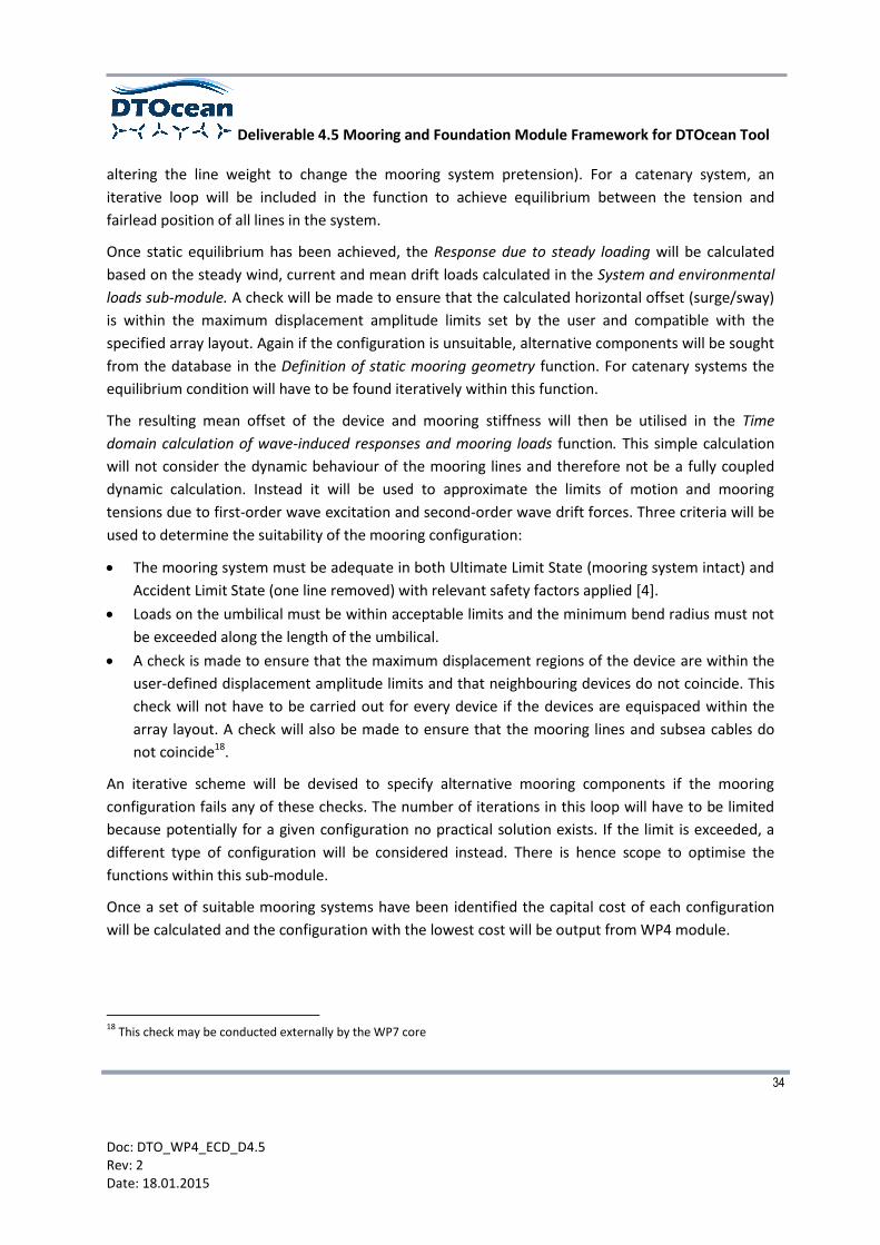
3.4.5 Foundation sub-module
If the device is fixed, foundations instead of anchors will be considered. Alternatively the user may
have a particular foundation type in mind in order for the foundation to be compatible with the
support structure. If particular types have been specified by the user, the Foundation type decision
tree will be skipped. For a fixed system it will be necessary for the user to specify the location of the
foundation points with respect to the local system origin.
The Foundation type decision tree will query site information (i.e. bathymetry, soil type, soil depth
and layering) specified by the user as well as accessing the database of foundation and anchor
components to determine the most suitable range of foundation or anchor technologies. The
decision tree will comprise a number of matrices (see examples given in Appendix A2), such as the
Soil matrix. The Soil matrix will be used to determine the suitability of the available foundation
options for particular soil types, with a score assigned to each option. Utilising the definitions given
in [1] the scores could relate to ‘1=functions well, 2=normally not the preferred choice, 3=does not
perform well’. The foundation type with lowest score would be considered to be the most feasible.
Figure 14: Functions within the Foundation sub-module

Deliverable 4.5 Mooring and Foundation Module Framework for DTOcean Tool
36
Doc: DTO_WP4_ECD_D4.5 Rev: 2 Date: 18.01.2015
In the case of a moored device, anchor positions and load vectors will be used to determine suitable
anchoring systems19, which will be determined based on soil type, soil depth and layering in addition
to load direction (with the latter originating from the Mooring sub-module). If shared anchoring
points are deemed to be feasible by the Mooring sub-module then this will also limit the selection of
anchor types to those which can are compatible with multi-directional loads. For fixed structures,
soil type (including depth and layering) will be the main deciding factor. Soil heterogeneity across
the site could result in several different foundation or anchor solutions. For an array of devices a
large selection of foundation or anchor types will not be practicable nor economically viable, and
hence the free selection will probably have to be constrained, particularly for large footprint, spread
mooring systems.
Each foundation type will have its own calculation procedure, as indicated in Figure 14. Most
approaches involve first determining the applied loads, applying safety factors and then based on
the supplied soil parameters, the size and/or penetration depth of the foundation are adjusted
iteratively to suit the application. This process could be optimised. Basic structural (stress) analysis
will only be conducted for pile foundations.
Any calculations associated with installation requirements will then be performed to inform logistical
operations planning conducted by the WP5 module.
Once a set of suitable foundation systems have been identified the capital cost of each configuration
will be calculated and the configuration with the lowest cost will be output from the WP4 module.
3.4.6 Substation sub-module
This will operate in a similar way to the Foundation sub-module, albeit it will consider only pile
foundations (i.e. monopiles for above-water substations and pin piles for substations mounted
directly on the seafloor). The location and features of the substation will be determined by the WP3
module, with static loads calculated within the System and environmental loads sub-module. Once a
set of suitable foundation systems have been identified the capital cost of each configuration will be
calculated and the configuration with the lowest cost will be output from the WP4 module.
19
In Section 3.1 it was shown that different approaches exist for mooring and foundation design. For moored devices, the
analysis of anchors within the Foundation sub-module will therefore be conducted using mooring-specific certification
approaches (i.e. [4]).

Deliverable 4.5 Mooring and Foundation Module Framework for DTOcean Tool
37
Doc: DTO_WP4_ECD_D4.5 Rev: 2 Date: 18.01.2015
Figure 15: Functions within the Substation sub-module
Any calculations associated with installation requirements will then be performed to inform
installation planning within the WP5 module.

Deliverable 4.5 Mooring and Foundation Module Framework for DTOcean Tool
38
Doc: DTO_WP4_ECD_D4.5 Rev: 2 Date: 18.01.2015
4 WP4 MODULE OUTPUTS
The WP4 module outputs are listed in this section, including the SI unit, format and destination of
each parameter.
Parameter SI Unit Scale type Output Class
Destination
Comments
WP3 WP5 WP6 WP7
Device ID number N/A Nominal X Identification number of each device
Configuration list N/A Nominal Economics X Lowest capital cost solution
Configuration category N/A X e.g. taut-moored, gravity base structure
Configuration hierarchy N/A Nominal Reliability X Structure comprising component ID numbers
Configuration volume m Ratio (x,y,z) Environmental X Used for environmental impact assessment. Occupying volume specified by co-ordinates
Configuration size m Ratio (x,y,z) principal dimensions X For fixed structures this will be the same as ‘Configuration volume’
Configuration dry mass kg Ratio X
Configuration wet mass kg Ratio X
Umbilical length m Ratio X Used by WP3 to calculate transmitted power
Component quantity N/A Ratio Economics and reliability
X X
Component size m Ratio (x,y,z) principal dimensions X
Configuration bill of materials Various Various Economics X
Bill of materials listing the overall configuration cost with a breakdown of all component names, component quantities and prices
Configuration environmental impact
N/A TBD Environmental X Metric to be determined
Maximum fairlead loads N Ratio X For log file
Maximum anchor loads N Ratio X For log file
Maximum structure loads N Ratio X For log file
Maximum structure moments Nm Ratio X For log file
Maximum device displacements (translational)
m Ratio X deltax, deltay, deltaz for log file
Maximum device displacements (rotational)
deg Ratio X deltaroll, deltapitch, deltayaw for log file
Key seafloor parameters and bathymetry at installation locations
Various N/A X Key parameters to include: soil types, maximum and minimum water depths, layering

Deliverable 4.5 Mooring and Foundation Module Framework for DTOcean Tool
39
Doc: DTO_WP4_ECD_D4.5 Rev: 2 Date: 18.01.2015
Parameter SI Unit Format Output Class
Destination
Comments
WP3 WP5 WP6 WP7
Foundation/anchor installation depth
m Ratio X e.g. for pile driving
Maximum foundation lowering rate
m/s Ratio X Installation limit
Foundation installation force N Ratio X For piles
Necessary under-pressure Pa Numeric X For suction caisson foundations or anchors
Vertical pull-out resistance (ultimate vertical bearing capacity)
N Ratio X For suction caisson foundations or anchors
Maximum horizontal resistance
N Ratio X For suction caisson foundations or anchors
Required anchor installation load
N Ratio X
Required installation time s Ratio X
e.g. interval during which installation load must be applied to anchor or grout curing time
Table 12: WP4 module outputs
The two main outputs from the WP4 module will be the Configuration hierarchy and the
Configuration bill of materials. The Configuration hierarchy will be used by the WP5 module to plan
logistics (i.e. to determine the order of component or sub-system installation) and the WP6 module
to assess system reliability. The Configuration bill of materials will provide the user with a list of all of
the components defined by the WP4 module as well as component quantity, unit cost and total
price. This list will be based on the capital cost calculation carried out by each sub-module. A
possible approach for defining the Configuration hierarchy is provided in Appendix A4.
Additional information in the form of a log file could also be outputted from the WP4 module,
describing maximum loads, moments and displacements from the static and quasi-static analysis.
Deliverable 4.5 Mooring and Foundation Module Framework for DTOcean Tool
40
Doc: DTO_WP4_ECD_D4.5 Rev: 2 Date: 18.01.2015
5 CONCLUSIONS
The main aim of the Tool will be to provide an initial assessment of several aspects of MRE array
design. The role of the WP4 module within the Tool will be to generate suitable mooring and
foundation solutions based on information originating from several sources; the user, the other
design modules as well as drawing from the built-in database. It is acknowledged that in order to
rapidly produce suitable mooring and foundation solutions a compromise between analysis
complexity and calculation time will be required within the module. Simplified design approaches
utilising linear and non-linear input parameters from referenced sources will be used for this task.
The module is not intended to replace existing mooring system or geotechnical software, but instead
provide a preliminary assessment to determine a solution which is both technically and logistically
feasible. The assessment conducted by the WP4 module will enable the user to focus on a suitable
design and conduct subsequent analysis using software of their choice.
Within this Deliverable report the proposed functions of WP4 mooring and foundation module have
been defined within the context of the DTOcean Tool. A high-level summary of the proposed module
has been provided in this report indicating the expected interaction of the module with the other
Tool modules, user and database via the WP7 core. The first run of the Tool will most likely be
sequential, starting at WP2 (array layout), followed by WP3 (electrical infrastructure), then WP4 and
finally WP5 (lifecycle logistics) and WP6 (system control and operation). Subsequent runs of the Tool
will include feedback from WP5 or WP6 with regard to logistics or reliability in the form of
constraints which will channel the design of the mooring or foundation towards an optimum
solution. Having defined the WP4 module framework, the next stage will be to develop a ‘black box’
version of the module for integration with the other Tool modules including definition of the
relevant feedback mechanisms.
Deliverable 4.5 Mooring and Foundation Module Framework for DTOcean Tool
41
Doc: DTO_WP4_ECD_D4.5 Rev: 2 Date: 18.01.2015
6 BIBLIOGRAPHY
[1] D. Thompson and D. J. Beasley, Handbook for Marine Geotechnical Engineering: SP-2209-OCN,
Books Express Publishing, 2012.
[2] J. V. Barrie and K. W. Conway, “Seabed characterization for the development of marine
renewable energy on the Pacific margin of Canada,” Continental Shelf Research, vol. 83, pp. 45-
52, 2013.
[3] International Electrotechnical Commission, “IEC 62600-10 TS Ed.1: Marine energy - Wave, tidal
and other water current converters - Part 10: Assessment of mooring system for Marine Energy
Converters (MECs),” 2014.
[4] Det Norske Veritas, “Position Mooring: DNV-OS-E301,” 2013.
[5] Det Norske Veritas, “Environmental Conditions and Environmental Loads: DNV-RP-C205,” 2010.
[6] Det Norske Veritas, “Foundations. Classification Notes No. 30.4,” 1992.
[7] Det Norske Veritas, “Design of Floating Wind Turbine Structures. DNV-OS-J103,” 2013.
[8] Det Norske Veritas, “Design of Offshore Wind Turbine Structures. DNV-OS-J101,” 2011.
[9] Det Norske Veritas, “Subsea Power Cables in Shallow Water Renewable Energy Applications,”
2014.
[10] American Petroleum Institute, “Planning, Designing and Constructing Fixed Offshore Platforms -
Working Stress Design. API-2A-WSD,” 2010.
[11] O. M. Faltinsen, Sea loads on ships and offshore structures, Cambridge University Press, 1990.
[12] S. Chakrabarti, Handbook of Offshore Engineering, Oxford, United Kingdom: Elsevier, 2005.
[13] E. T. R. Dean, Offshore geotechnical engineering. Principals and practice, London, UK: Thomas
Telford Limited, 2010.
[14] Det Norske Veritas, “Certification of Tidal and Wave Energy Converters,” 2008.
Deliverable 4.5 Mooring and Foundation Module Framework for DTOcean Tool
42
Doc: DTO_WP4_ECD_D4.5 Rev: 2 Date: 18.01.2015
[15] Bureau Veritas, “Current and Tidal Turbines, Rule Note, NI 603 DT R00 E,” 2013.
[16] American Petroleum Institute, “Recommended Practice for Design and Analysis of
Stationkeeping Systems for Floating Structures. API RP 2SK,” 1996.
[17] Bureau Veritas, “Classification of Mooring Systems for Permanent Offshore Units. NR 493 DT
R02 E,” 2012.
[18] International Standards Organisation, “Petroleum and natural gas industries -- Specific
requirements for offshore structures -- Part 7: Stationkeeping systems for floating offshore
structures and mobile offshore units: ISO19901-7:2013,” 2013.
[19] DTOcean, “Deliverable 4.3 – Report on suitability of assessment functions to validate novel
mooring and foundation component designs,” 2014.
[20] DTOcean, “Deliverable 4.1 - A comprehensive assessment of the applicability of available and
proposed offshore mooring and foundation technologies and design tools for array
applications,” 2014.
[21] W. Ruan, Y. Bai and P. Cheng, “Static analysis of deepwater lazy-wave umbilical on elastic
seabed,” Ocean Engineering, vol. 91, pp. 73-83, 2014.
[22] J. Fitzgerald and L. Bergdahl, “Considering Mooring Cables for Offshore Wave Energy
Converters,” in Proceedings of the 7th European Wave and Tidal Energy Conference, Porto,
Portugal, 2007.
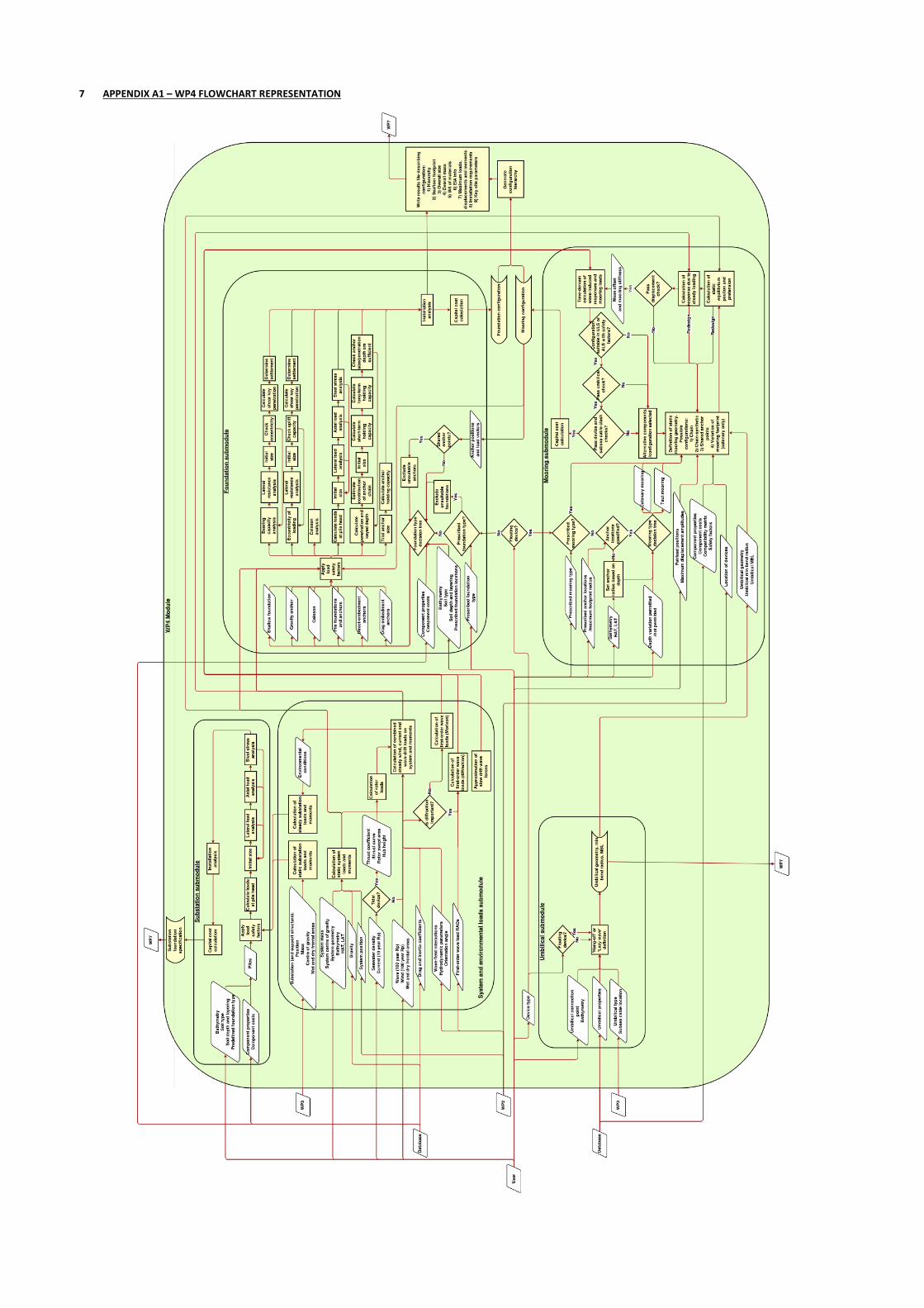
7 APPENDIX A1 – WP4 FLOWCHART REPRESENTATION

8 APPENDIX A2 - PROPOSED FOUNDATION SUB-MODULE DECISION MATRIX
Below is a proposed approach to determining the suitable range of foundations for analysis within
the Foundation sub-module adapted from [1]. Separate matrices are presented for soil type, seafloor
topography, soil depth, loading direction and magnitude20; this could be implemented in the Tool
database as a single look-up table.
Soil type Shallow Gravity Pile Suction caisson Direct embedment Drag
Soft clay, mud 1 1 2 1 1 1
Stiff clay 1 1 1 1 1 1
Sand 1 1 1 1 1 1
Hard glacial till 2 1 1 3 1 2
Boulders 3 1 3 3 3 3
Soft rock or coral 3 1 1 3 1 3
Hard, monolithic rock 3 1 2 3 3 3
Table 13: Soil matrix listing the performance of foundation and anchor types as a function of seafloor
conditions
Seafloor topography Shallow Gravity Pile Suction caisson Direct embedment Drag
Moderate slopes < 10 deg 1 1 1 1 1 1
Steep slopes > 10 deg 3 3 1 2 2 3
Table 14: Topography matrix
Soil depth Shallow Gravity Pile Suction caisson
Direct embedment
Drag embedment Dense sand Soft clay/silt
None 3 1 1 3 3 3 3
0 m < Very shallow < 1 m 1 1 1 3 3 3 3
1 m ≤ Shallow < 6 m 1 1 1 2 3 2 3
6 m ≤ Moderate < 25 m 1 1 1 1 1 1 2
Deep ≥ 25 m 1 1 1 1 1 1 1
Table 15: Sensitivity to soil depth matrix
Loading direction Shallow Gravity Pile Suction caisson Direct embedment Drag
Downward load component (foundations)
1 1 1 1 3 3
Omni-directional (not down) 1 1 1 1 1 3
Uni-directional (not down) 1 1 1 1 1 1
Large uplift component 3 1 1 1 1 3
Table 16: Load direction matrix
Load magnitude Shallow Gravity Pile Suction caisson Direct embedment Drag
L < 444.8 kN 1 1 2 2 1 1
444.8 kN ≤ L ≤ 4448.2 kN
2 2 1 1 2 1
L > 4448.2 kN 3 3 1 1 3 3
20
These scores are illustrative and may be subject to change. In addition multiple load directions may be possible. The
required penetration depth of direct- and drag embedment anchors is typically technology dependent.

Deliverable 4.5 Mooring and Foundation Module Framework for DTOcean Tool
45
Doc: DTO_WP4_ECD_D4.5 Rev: 2 Date: 18.01.2015
Table 17: Load magnitude matrix
The approach to determining foundation suitability is based on a simple sum of each parameter,
with the lowest score deemed to be the most suitable for the site. Weighting could be applied to
each parameter.
Example 1:
A foundation is required for a fixed TEC (deadweight load: 1470kN) at site with steep sloping, deep
soft clay:
Pile = 2+1+1+1+1 = 6
Suction caisson = 1+2+1+1+1 = 6
Shallow = 1+3+1+1+2 = 8
Gravity = 1+3+1+1+2 = 8
Therefore in the first instance pile or suction caisson designs would be explored.
Example 2:
An anchor is required for a taut-moored WEC (tensile loads up to 100kN) at a hard rock site with a
fairly flat profile:
Gravity = 1+1+1+1+1 = 5
Pile = 2+1+1+1+2 = 7
Direct embedment = 3+1+3+1+1 = 9
Suction caisson = 3+1+3+1+2 = 10
Drag = 3+1+3+3+1 = 11
Shallow = 3+1+3+3+1 = 11
Therefore gravity anchors would be prioritised initially.
Of course in both examples a practicable design may not be achievable in which case the technology
with the second lowest score would be selected.
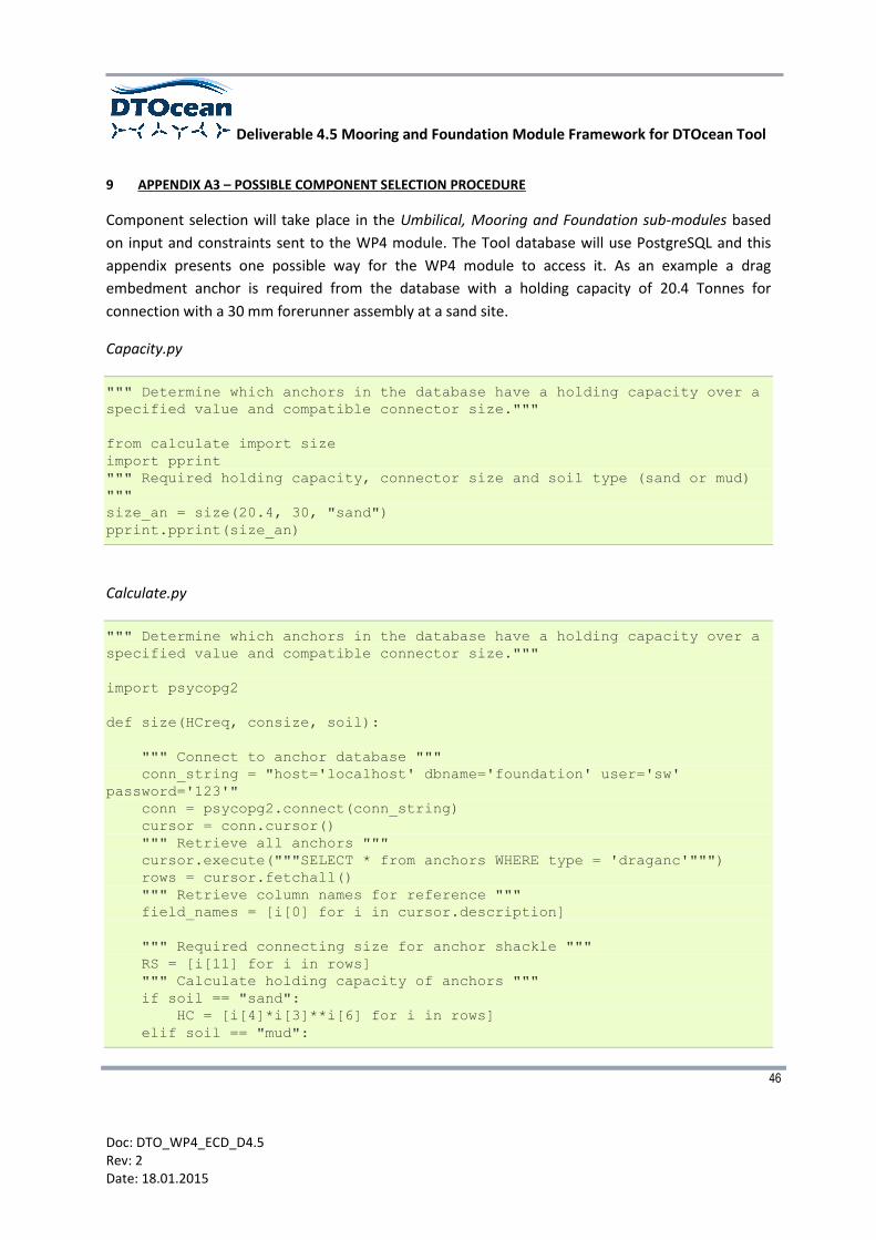
Deliverable 4.5 Mooring and Foundation Module Framework for DTOcean Tool
46
Doc: DTO_WP4_ECD_D4.5 Rev: 2 Date: 18.01.2015
9 APPENDIX A3 – POSSIBLE COMPONENT SELECTION PROCEDURE
Component selection will take place in the Umbilical, Mooring and Foundation sub-modules based
on input and constraints sent to the WP4 module. The Tool database will use PostgreSQL and this
appendix presents one possible way for the WP4 module to access it. As an example a drag
embedment anchor is required from the database with a holding capacity of 20.4 Tonnes for
connection with a 30 mm forerunner assembly at a sand site.
Capacity.py
""" Determine which anchors in the database have a holding capacity over a
specified value and compatible connector size."""
from calculate import size
import pprint
""" Required holding capacity, connector size and soil type (sand or mud)
"""
size_an = size(20.4, 30, "sand")
pprint.pprint(size_an)
Calculate.py
""" Determine which anchors in the database have a holding capacity over a
specified value and compatible connector size."""
import psycopg2
def size(HCreq, consize, soil):
""" Connect to anchor database """
conn_string = "host='localhost' dbname='foundation' user='sw'
password='123'"
conn = psycopg2.connect(conn_string)
cursor = conn.cursor()
""" Retrieve all anchors """
cursor.execute("""SELECT * from anchors WHERE type = 'draganc'""")
rows = cursor.fetchall()
""" Retrieve column names for reference """
field_names = [i[0] for i in cursor.description]
""" Required connecting size for anchor shackle """
RS = [i[11] for i in rows]
""" Calculate holding capacity of anchors """
if soil == "sand":
HC = [i[4]*i[3]**i[6] for i in rows]
elif soil == "mud":
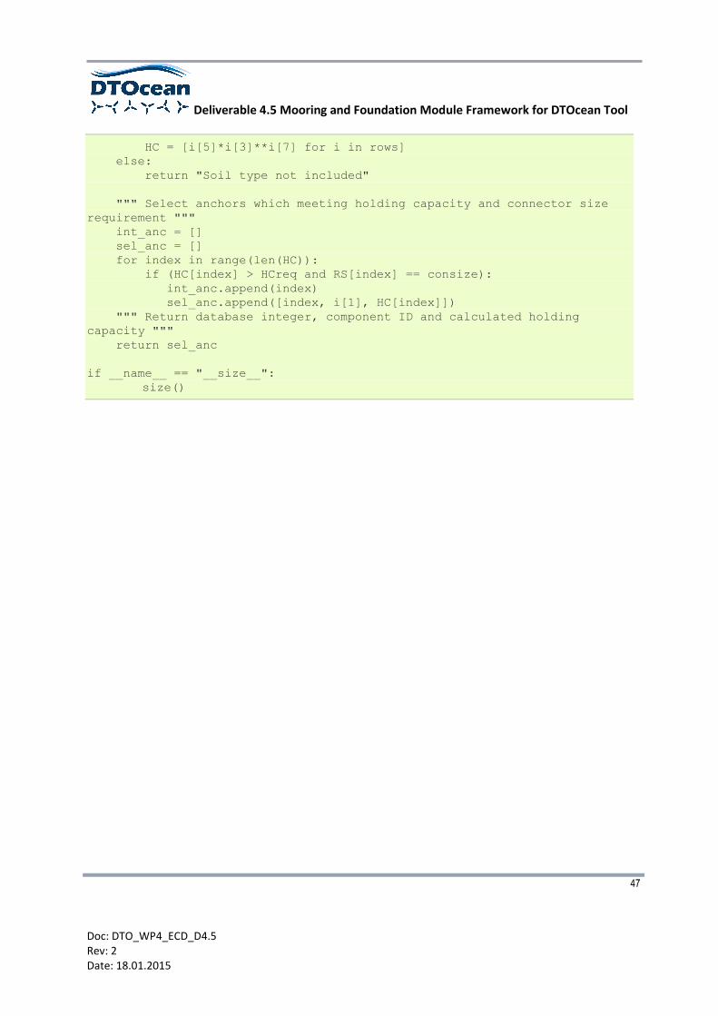
Deliverable 4.5 Mooring and Foundation Module Framework for DTOcean Tool
47
Doc: DTO_WP4_ECD_D4.5 Rev: 2 Date: 18.01.2015
HC = [i[5]*i[3]**i[7] for i in rows]
else:
return "Soil type not included"
""" Select anchors which meeting holding capacity and connector size
requirement """
int_anc = []
sel_anc = []
for index in range(len(HC)):
if (HC[index] > HCreq and RS[index] == consize):
int_anc.append(index)
sel_anc.append([index, i[1], HC[index]])
""" Return database integer, component ID and calculated holding
capacity """
return sel_anc
if __name__ == "__size__":
size()
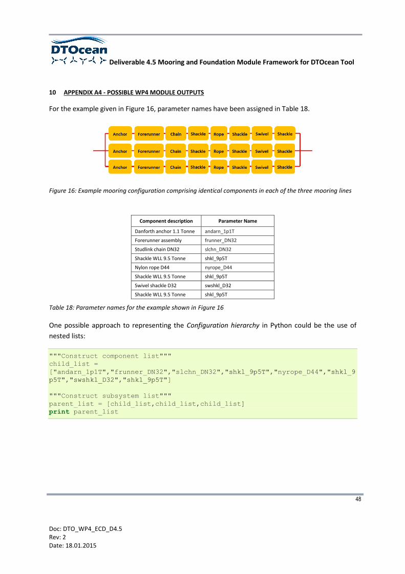
Deliverable 4.5 Mooring and Foundation Module Framework for DTOcean Tool
48
Doc: DTO_WP4_ECD_D4.5 Rev: 2 Date: 18.01.2015
10 APPENDIX A4 - POSSIBLE WP4 MODULE OUTPUTS
For the example given in Figure 16, parameter names have been assigned in Table 18.
Figure 16: Example mooring configuration comprising identical components in each of the three mooring lines
Component description Parameter Name
Danforth anchor 1.1 Tonne andarn_1p1T
Forerunner assembly frunner_DN32
Studlink chain DN32 slchn_DN32
Shackle WLL 9.5 Tonne shkl_9p5T
Nylon rope D44 nyrope_D44
Shackle WLL 9.5 Tonne shkl_9p5T
Swivel shackle D32 swshkl_D32
Shackle WLL 9.5 Tonne shkl_9p5T
Table 18: Parameter names for the example shown in Figure 16
One possible approach to representing the Configuration hierarchy in Python could be the use of
nested lists:
"""Construct component list"""
child_list =
["andarn_1p1T","frunner_DN32","slchn_DN32","shkl_9p5T","nyrope_D44","shkl_9
p5T","swshkl_D32","shkl_9p5T"]
"""Construct subsystem list"""
parent_list = [child_list,child_list,child_list]
print parent_list

Deliverable 4.5 Mooring and Foundation Module Framework for DTOcean Tool
49
Doc: DTO_WP4_ECD_D4.5 Rev: 2 Date: 18.01.2015
The Configuration bill of materials will utilise the capital cost calculation which will be carried out in
the Mooring, Foundation and Substation sub-modules. To construct the Configuration bill of
materials the number of instances of each component in the configuration of each device will be
counted:
"""Merge subassembly list"""
merged = sum(parent_list,[])
"""Determine total component quantities in subsystem"""
from collections import Counter
Counter(merged)
print merged
By retrieving the cost information for each component, the quantity of each component can be used
to calculate the total capital cost of each configuration.