delayed coker switch ball valve - documents |...
TRANSCRIPT
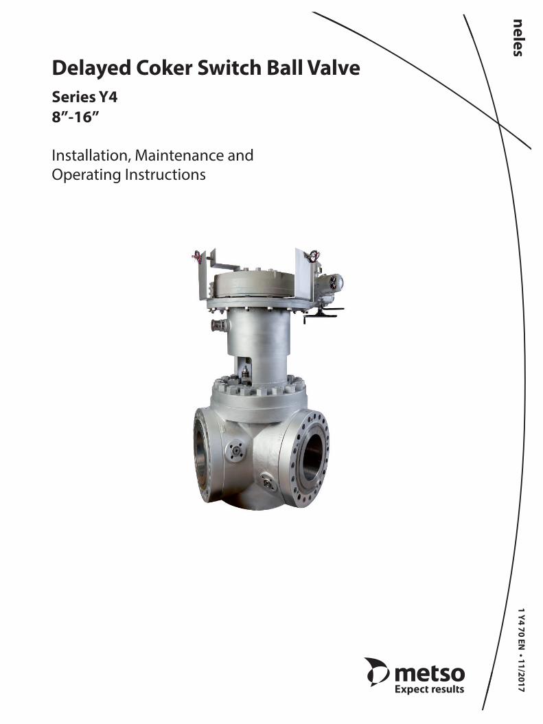
1 Y4 70 EN • 11/2017
Delayed Coker Switch Ball ValveSeries Y48”-16”
Installation, Maintenance and Operating Instructions

Subject to change without notice.All trademarks are property of their respective owners.
TABLE OF CONTENTS
1. GENERAL ................................................................... 31.1 Safety Precautions ........................................................ 31.2 Valve Markings .............................................................. 3
2. INSTALLATION ......................................................... 33. MAINTENANCE ......................................................... 4
3.1 Disassembly .................................................................... 43.2 Assembly .......................................................................... 5
4. TESTING .................................................................... 65. THREADED FASTENER TORQUES ............................ 76. SERVICE..................................................................... 97. REPAIR KITS/SPARE PARTS ..................................... 98. HOW TO ORDER ..................................................... 11
IMO 11/17
2 1 Y4 70 EN
READ THESE INSTRUCTIONS FIRST!
These instructions provide information about safe handling and operation of the valve.If you require additional assistance, please contact the manufacturer or manufacturer’s representative.Addresses and phone numbers are printed on the back cover.See also www.metso.com/valves for the latest documentation.
SAVE THESE INSTRUCTIONS!

1. GENERAL
This manual provides the essential information about the installation, maintenance and troubleshooting of Series Y4 ball valves. For more information on actuators and other equipment, which are only covered briefly, please refer to the separate manuals on their installation, use and maintenance. Please read these instructions carefully and save them for future reference.
WARNINGAS THE USE OF THE VALVE IS APPLICATION SPECIFIC, A NUMBER OF FACTORS SHOULD BE TAKEN INTO ACCOUNT WHEN SELECTING A VALVE FOR A GIVEN APPLICATION. THEREFORE, SOME OF THE SITUATIONS IN WHICH THE VALVES ARE USED ARE OUTSIDE THE SCOPE OF THIS MANUAL. IF YOU HAVE ANY QUESTIONS CONCERNING THE USE, APPLICATION OR COMPATIBILITY OF THE VALVE WITH THE INTENDED SERVICE, CONTACT METSO FOR MORE INFORMATION.
1.1 Safety Precautions
WARNINGSEAT AND BODY RATINGS!THE PRACTICAL AND SAFE USE OF THIS PRODUCT IS DETERMINED BY BOTH THE SEAT AND BODY RATINGS. READ THE IDENTIFICATION PLATE AND CHECK BOTH RATINGS. THIS PRODUCT IS AVAILABLE WITH A VARIETY OF SEAT MATERIALS. SOME OF THE SEAT MATERIALS HAVE PRESSURE RATINGS THAT ARE LESS THAN THE BODY RATINGS. ALL OF THE BODY AND SEAT RATINGS ARE DEPENDENT ON VALVE TYPE AND SIZE, SEAT MATERIAL, AND TEMPERATURE. DO NOT EXCEED THESE RATINGS!
WARNINGDO NOT EXCEED THE PERFORMANCE LIMITATIONS!EXCEEDING THE PERFORMANCE LIMITATIONS MARKED ON THE VALVE MAY RESULT IN VALVE DAMAGE OR EVEN IN UNCONTROLLED PRESSURE RELEASE. DAMAGE OR PERSONAL INJURY MAY RESULT.
WARNINGDO NOT REMOVE OR DISMANTLE A PRESSURIZED VALVE! REMOVING OR DISMANTLING A PRESSURIZED VALVE WILL CAUSE AN UNCONTROLLED PRESSURE RELEASE. ALWAYS SHUT OFF THE PIPELINE, RELEASE THE PRESSURE AND REMOVE THE MEDIUM BEFORE REMOVING OR DISMANTLING THE VALVE. IDENTIFY THE MEDIUM, PROTECT YOURSELF AND THE ENVIRONMENT AGAINST ANY HARMFUL OR POISONOUS SUBSTANCES. PREVENT THE MEDIUM FROM ENTERING THE PIPES DURING MAINTENANCE. FAILURE TO DO THIS MAY RESULT IN DAMAGE OR PERSONAL INJURY.
WARNINGBEWARE OF THE CUTTING MOVEMENT OF THE BALLKEEPS HANDS, OTHER PARTS OF YOUR BODY, TOOLS AND OTHER OBJECTS OUT OF THE OPEN FLOW PORT. ALSO MAKE SURE THAT NO FOREIGN OBJECTS ENTER THE PIPELINE. CLOSE AND DETACH THE ACTUATOR PRESSURE SUPPLY FOR MAINTENANCE. FAILURE TO DO THIS MAY RESULT IN DAMAGE OR PERSONAL INJURY. FAILURE TO DO THIS MAY RESULT IN DAMAGE OR PERSONAL INJURY.
WARNINGBEWARE OF EXTREME TEMPERATURES!THE VALVE BODY MAY BE VERY HOT OR VERY COLD. PROTECT PEOPLE AGAINST FROSTBITES AND BURNS.
WARNINGWHEN HANDLING THE VALVE OR THE VALVE PACKAGE, REMEMBER ITS WEIGHT!DO NOT LIFT THE VALVE OR THE VALVE PACKAGE FROM THE ACTUATOR, POSITIONER, LIMIT SWITCH OR THEIR PIPES. WHEN LIFTING THE VALVE, USE THE DESIGNATED LIFTING HOLES IN THE BODY/INSERTS/COVER. DAMAGE OR PERSONAL INJURY MAY RESULT FROM FALLING PARTS.
1.2 Valve Markings
The body markings are cast or stamped on the body side. The identification plate (Figure 1) is attached to the valve flange.
The identification plate has the following markings:
1. Body material 2. Ball material3. Shaft material4. Seat material5. Maximum operating temperature 6. Minimum operating temperature 7. Maximum shut-off pressure differential8. Type code9. Manufacturing number10. Pressure class
2. INSTALLATION
1. Check that the valve and the additional equipment have not been damaged during transportation.
2. Flush or blow the pipes clean before mounting the valve. Impurities such as sand and parts of welding electrodes could damage the ball surface and the seats.
3. Install shouldered eye bolts into the tapped holes of the flange stud holes. Lift the valve using the three eyebolts. Do not lift by one eyebolt. See Table 1 for a list of eyebolt sizes based on valve size. As an alternative, place the hoisting cables around the valve body. Do not
IMO 11/17
1 Y4 70 EN 3
(1) (2)(3) (5)(6)(7) (8) (9) (10)
Figure 1 Identification plate
(4)
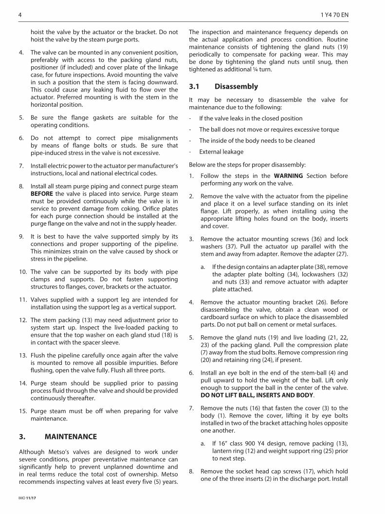
hoist the valve by the actuator or the bracket. Do not hoist the valve by the steam purge ports.
4. The valve can be mounted in any convenient position, preferably with access to the packing gland nuts, positioner (if included) and cover plate of the linkage case, for future inspections. Avoid mounting the valve in such a position that the stem is facing downward. This could cause any leaking fluid to flow over the actuator. Preferred mounting is with the stem in the horizontal position.
5. Be sure the flange gaskets are suitable for the operating conditions.
6. Do not attempt to correct pipe misalignments by means of flange bolts or studs. Be sure that pipe-induced stress in the valve is not excessive.
7. Install electric power to the actuator per manufacturer’s instructions, local and national electrical codes.
8. Install all steam purge piping and connect purge steam BEFORE the valve is placed into service. Purge steam must be provided continuously while the valve is in service to prevent damage from coking. Orifice plates for each purge connection should be installed at the purge flange on the valve and not in the supply header.
9. It is best to have the valve supported simply by its connections and proper supporting of the pipeline. This minimizes strain on the valve caused by shock or stress in the pipeline.
10. The valve can be supported by its body with pipe clamps and supports. Do not fasten supporting structures to flanges, cover, brackets or the actuator.
11. Valves supplied with a support leg are intended for installation using the support leg as a vertical support.
12. The stem packing (13) may need adjustment prior to system start up. Inspect the live-loaded packing to ensure that the top washer on each gland stud (18) is in contact with the spacer sleeve.
13. Flush the pipeline carefully once again after the valve is mounted to remove all possible impurities. Before flushing, open the valve fully. Flush all three ports.
14. Purge steam should be supplied prior to passing process fluid through the valve and should be provided continuously thereafter.
15. Purge steam must be off when preparing for valve maintenance.
3. MAINTENANCE
Although Metso’s valves are designed to work under severe conditions, proper preventative maintenance can significantly help to prevent unplanned downtime and in real terms reduce the total cost of ownership. Metso recommends inspecting valves at least every five (5) years.
The inspection and maintenance frequency depends on the actual application and process condition. Routine maintenance consists of tightening the gland nuts (19) periodically to compensate for packing wear. This may be done by tightening the gland nuts until snug, then tightened as additional ¼ turn.
3.1 Disassembly
It may be necessary to disassemble the valve for maintenance due to the following:
- If the valve leaks in the closed position
- The ball does not move or requires excessive torque
- The inside of the body needs to be cleaned
- External leakage
Below are the steps for proper disassembly:
1. Follow the steps in the WARNING Section before performing any work on the valve.
2. Remove the valve with the actuator from the pipeline and place it on a level surface standing on its inlet flange. Lift properly, as when installing using the appropriate lifting holes found on the body, inserts and cover.
3. Remove the actuator mounting screws (36) and lock washers (37). Pull the actuator up parallel with the stem and away from adapter. Remove the adapter (27).
a. If the design contains an adapter plate (38), remove the adapter plate bolting (34), lockwashers (32) and nuts (33) and remove actuator with adapter plate attached.
4. Remove the actuator mounting bracket (26). Before disassembling the valve, obtain a clean wood or cardboard surface on which to place the disassembled parts. Do not put ball on cement or metal surfaces.
5. Remove the gland nuts (19) and live loading (21, 22, 23) of the packing gland. Pull the compression plate (7) away from the stud bolts. Remove compression ring (20) and retaining ring (24), if present.
6. Install an eye bolt in the end of the stem-ball (4) and pull upward to hold the weight of the ball. Lift only enough to support the ball in the center of the valve. DO NOT LIFT BALL, INSERTS AND BODY.
7. Remove the nuts (16) that fasten the cover (3) to the body (1). Remove the cover, lifting it by eye bolts installed in two of the bracket attaching holes opposite one another.
a. If 16” class 900 Y4 design, remove packing (13), lantern ring (12) and weight support ring (25) prior to next step.
8. Remove the socket head cap screws (17), which hold one of the three inserts (2) in the discharge port. Install
IMO 11/17
4 1 Y4 70 EN

an eye bolt in the flange stud hole, on the OD of the insert and remove the insert. Repeat these steps for the remaining two inserts when placing the inserts down, place them with the seat cavity facing up.
9. Lift the ball up and away from the body (1), using care to insure the ball does not hit the body.
10. Disassemble each of the three insert assemblies which include the insert, seat (5) and E-ring (6). The components of each insert assembly are matched in sets. DO NOT intermix.
3.2 Assembly
1. Clean all valve components carefully. If necessary, use suitable solvents.
2. Inspect all components for damage before reassembling the valve. Look for damage to the seating areas, stem, body, and body cap, and look for wear in the bearing areas. Replace any damaged parts.
3. Check whether the sealing surface of the ball or the seats (5) are damaged. If only the seats are damaged, the valve can be put in operating order by replacing the seats.
NOTE: The seats (5) and inserts (2) of this valve are custom fitted to the Stem-Ball (4). Replacing one of these components requires each to be refitted. Contact your local Metso service center when replacing seats, inserts or Stem-Balls, or performing major repairs.
Minor scratches in the ball surface or the seats can be smoothed with a fine grinding cloth (600 or finer, wet or dry paper). If the sealing surfaces of the ball are damaged, it is highly recommended the valve is repaired at a Metso Service Center or replaced. If sent to the factory, properly reassemble the valve for shipment.
4. Check the condition of the seat E-ring seals (6), especially the end sealing surfaces and the mating surfaces on the back of the seat and seat insert to insure good sealing on both ends of the seals.
5. Check the condition of the thrust bearing (11) and its mating surfaces on the top of the ball and the bottom of the cover. Replace the bearing if it is galled or worn. Minor defects may be removed by lapping with (600 or finer grit) lapping compound.
6. Check the condition of the ball-stem in the area that mates with the packing. Remove any axial scratches or surface roughness by polishing the surface with fine emery paper. Always move the emery paper around the stem. Do not move the emery paper along the vertical axis of the stem as this may put scratches on the stem which could provide a leakage path along the stem.
7. Obtain a clean piece of wood or cardboard. With the flange face down, place insert “A” on the wood or cardboard.
8. Lubricate the matched set E-ring seal surfaces on the insert and seats with liquid form COPALTITE®. Place the E-ring seal (6) in position in the insert seat cavity.
9. Lower the matched seat (5) into position on top of the E-ring seal.
10. Assemble the appropiate insert seals in the following manner:
a. If the graphite ribbon, wrap 1/2” graphite ribbon (9) eight times around the sealing diameter of the insert for each location that requires it. Use a small piece of transparent tape to hold the end in place.
b. If Flexitallic seals, assemble the appropiate seal (9, 10) in the correct sealing area on the insert (2).
Insert “A” subassembly is complete. Follow the same procedure and assemble inserts “B” and “C”.
11. Screw a lifting eyebolt into the threaded hole in the stem end of the stem-ball (4).
12. Place the body (1) on a piece of wood or cardboard, resting on its inlet flange face.
13. Lift the stem-ball, coat the ball surface with pure nickel NEVER-SEEZ® or equivalent and carefully lower into the body through the top opening. Leave the ball suspended approximately 2” from the bottom of the body cavity.
14. Lift insert subassembly “A” and carefully slide it into Port “A”.
NOTE: The insert subassembly may be lifted manually or by an eyebolt screwed into the tapped hole on the top of the insert flange. THE “A” ON THE BODY MUST LINE UP WITH THE “A” ON THE INSERT.
15. Repeat step 13 for insert subassemblies “B” and “C”.
16. Raise or lower the stem-ball until the seats nest into the ball.
17. Partially thread the insert socket head cap screws (17) into the body.
IMO 11/17
1 Y4 70 EN 5
AA
Figure 2
Insert CavitySealing Surface
E-Ring SealingSurface
E-Ring SealingSurface
Seat SealingSurface

18. Pushing insert “A” by hand, check with a feeler gage that the seat is in contact all around with the ball. Torque the socket head cap screws to the value shown in The Threaded Fastener Torques section (See Table 1).
19. Repeat steps 16 and 17 for insert subassemblies “B” and “C”.
20. Clean the stem-ball thrust bearing (11) and coat both sides with pure nickel NEVER-SEEZ® or equivalent.
21. Slide the bearing (large chamfer down) down the stem into contact with the ball.
22. Clean the cover (4). Wrap ½” ribbon graphite (9) 14 times around the cover sealing diameter, using a small piece of transparent tape to hold the end in place. Place the cover gasket (8) into the machined cavity in the body.
23. After positioning the cover, coat the studs (15) with pure nickel NEVER-SEEZ® or equivalent and thread into the body if they have been removed.
24. The studs should stand above the cover one nut (16) height, plus one or two threads.
25. Thread on all the cover nuts (16) and torque to the value shown in The Threaded Fastener Torques section.
26. Install the lantern ring (12) into the bottom of the packing bore. Install bottom braided packing ring (13), die formed center rings (14), and top braided packing ring (13) into the packing bore.
a. If the valve is a 16” Class 900 design, the weight support rings (25) must be installed prior to the lantern ring. The ball (4) must be supported in order for the weight support clips to be assembled. Once in place at the bottom of the packing bore, the ball support can be released slowly until the weight of the ball is supported by the weight support ring.
27. Position the compression ring (20), retaining ring (24), if present and gland follower (7). Coat the studs (18) with pure nickel NEVER-SEEZ® or equivalent and thread into the cover, if they have been previously removed. Install live loading Belleville springs (21), guide bushings (22) and washers (23). Thread on the hex nuts (19) finger tight as they will be tightened as required to stop leakage during the hydro test.
28. Insert the key (28) into the stem-ball key slot and coat the ball stem with pure nickel NEVER-SEEZ® or equivalent.
29. Install the adapter (27) and adapter key (29) on the stem-ball shaft and coat the coupling shaft with pure nickel NEVER-SEEZ® or equivalent.
30. Coat the bracket cap screws (34) with pure nickel NEVER-SEEZ®or equivalent and attach the bracket (26) to the top of the cover using flat or lock washers (35).
31. If the bracket design uses an adapter plate (38), assemble the adapter plate to the actuator using the appropriate hex head cap screws (36) and lock washer (37). Torque these and the bracket mounting screws according to The Threaded Fastener Torque section. Depending on which port the actuator hangs over, the hex head cap screws (34) and washers (32) that are covered by the overhang will need to be placed in their installed location prior to actuator being attached.
32. Hoist the actuator and position onto the coupling such that the position indicator aligns with the flow port in the ball. Rotate actuator and ball as necessary so flow through the ball will be at the port indicated by the actuator and that the actuator aligns with the mounting bracket screw holes.
a. If the design contains an adapter plate, attach the adapter plate (38) to the upper plate of the bracket subassembly (26) using hex head cap screws (31), washers (32) and nuts (33).
33. Coat the actuator mounting screws (36) with pure nickel NEVER-SEEZ® or equivalent. Thread in the actuator mounting screws (36) with washers (37). Torque these and the bracket mounting screws according to The Threaded Fastener Torques section.
34. The valve is now reassembled and ready for testing.
NOTE: Do not install optional locking pin (30) until valve testing is completed.
4. TESTING
1. Prepare the valve for testing by covering all pipe and purge ports with blind flanges equipped with a threaded (NPT) hole for water connection. Blind flanges shall be rated for the maximum pressure of the valve.
2. Complete a hydrostatic shell test for a minimum of 5 minutes. The pressure will be based on the Class of the valve. For class 300, the pressure is 1125 psi. For Class 600, the pressure is 2250 psi. For Class 900, the pressure is 3375 psi. To avoid damage to the seat seals during testing, turn the valve so that two of the ports are partially open. Install a bypass line between the closed port and one of the partially open ports. This will ensure that the metal seat seals are not subjected to excessive differential pressure.
WARNING: Do not perform the hydrostatic shell test without a properly installed bypass line. Damage could occur if high differential pressure is applied across the seat seals.
3. Conduct the seats leakage tests on each port in accordance with customer requirements.
IMO 11/17
6 1 Y4 70 EN

5. THREADED FASTENER TORQUES
During assembly, the threaded fasteners used should be clean and well lubricated with pure nickel NEVER-SEEZ® or equivalent. Torque cover in the sequence shown:
For all other bolt patterns (ie. insert cap screws, bracket cap screws, adapter plate cap screws) torque the screws in a star pattern to ensure even compression/load.
Torque each fastener for the cover insert, adapter plate and actuator as shown below:
1. Torque all fasteners to 1/3 specified torque, following sequence in Section 5, Figures 3-6.
2. Torque all fasteners to 2/3 specified torque, following sequence in Section 5, Figures 3-6.
3. Torque all fasteners to the specified torque. In Table 1, following sequence in Section 5, Figures 3-6.
4. Allow studs to relax for 5 minutes. Then re-torque to specified torque. In Table 1. Tighten in circular pattern - Do not criss cross.
5. After hydrostatic testing, re-torque all fasteners to the specified torque. In Table 1. Tighten in circular pattern - Do not criss cross.
IMO 11/17
1 Y4 70 EN 7
9
13
16
12
8
42 6
10
14
15
11
7
315
Figure 514” Class 600 Cover Tightening Sequence
610
14
18
15
11
7
315
9
13
17
16
12
8
42
Figure 616” Class 900 Cover Tightening Sequence
2
6
10
7
3
1
5
9
8
4
Figure 310” Class 300 Cover Tightening Sequence
6
10
11
7
3
15
9
12
8
4
2
Figure 410” Class 300, 10” and 12” Class 600, 10” Class 900 Tightening Sequence

IMO 11/17
8 1 Y4 70 EN
17
15 16
18 19
21
23
4
37
1 2
11
8
9
10
12
13
20
5
6
ASSEMBLY VIEWS AND PARTS LIST
Figure 7
PORT "A"
PORT "C"
PORT "B"
Bracket
Actuator
Inlet
ITEM NO.
DESCRIPTION QTY. SPARE PARTS
1 Body 1
2 Insert 3
3 Cover 1
4 Stem Ball 1
5 Seat 3 **
6 E-Ring 3 **
7 Compression Plate 1
8 Cover Gasket 1 **
9 Insert Gasket 3 **
10 Insert Gasket 3 **
11 Thrust Bearing 1 **
12 Lantern Ring 1
13 Packing 5 **
15 Cover Stud *
16 Cover Nut *
17 Insert Screws *
18 Gland Stud 4
19 Gland Nut 4
20 Compression Ring 1
21 Belleville Assy 4
22 Guide Bushing 4
23 Washer 4
24 Retaining Ring 1
25 Weight Support Ring*** 1
* Qty based on size and pressure class of construction.** Recommended Spare Parts.*** Only on 16” class 900 design see Figure 8.

TABLE 1
Fastener Torques
Cover studs & Nuts Socket Head Cap Screws Bracket Cap Screws Adapter Plate
Size Torque(ft*lbs)
Size Torque(ft*lbs)
Size Torque(ft*lbs)
Size Torque(ft*lbs)
8” Y4 Class 300 1-1/4-8UN 1140-1430 1-8UN 570-700 1-1/4-7UN 1170-1430 N/A N/A
10” Y4 Class 300 1-3/8-8UN 1600-1950 7/8-9UNC 380-470 1-1/4-7UN 1170-1430 N/A N/A
10” Y4 Class 600 1-3/8-8UN 1600-1950 7/8-9UNC 380-470 1-1/4-7UN 1170-1430 N/A N/A
10” Y4 Class 900 1-5/8-8UN 2800-3300 7/8-9UNC 380-470 1-1/2-6UNC 2100-2600 1/8UN 570-700
12” Y4 Class 600 1-5/8-8UN 2800-3300 7/8-9UNC 380-470 1-1/2-6UN 2100-2600 N/A N/A
12” Y4 Class 900 1-5/8-8UN 2800-3300 1-1/8-8UN 839-1009 1-1/2-6UN 2100-2600 1-8UN 570-700
14” Y4 Class 600 1-3/4-8UN 3124-3720 7/8-9UNC 380-470 1-3/4-8UN 3124-3720 N/A N/A
16” Y4 Class 900 2-8UN 4698-5306 1-1/8-8UN 839-1009 1-3/4-5UNC 2718-3360 1-8UN 570-700
6. SERVICE
We recommend that valves be directed to our service center for maintenance. The service centers are equipped to provide rapid turn around at reasonable cost and offer new valve warranty with all reconditioned valves.
7. REPAIR KITS/SPARE PARTS
For further information or assistance on repair kits and spare parts visit our website at www.metso.com/valves.
IMO 11/17
1 Y4 70 EN 9
WEIGHT SUPPORT RING
TOP VIEW - CROSS SECTION THROUGH SHAFT
WEIGHT SUPPORT RINGWEIGHT SUPPORT RINGWEIGHT SUPPORT RING
LANTERN RING
COMPRESSION PLATE
SIDE VIEW CROSS SECTION
STEM-BALL
LANTERN RING
COMPRESSION RING
PACKING
WEIGHT SUPPORT RING
RETAINING CLIP
Figure 8
16” Class 900

IMO 11/17
10 1 Y4 70 EN
31
32
34
30
35
26
29
27
28
33
38
37
36
* Qty based on size and pressure class of construction** Item may not be required depending on bracket design
ITEM NO. DESCRIPTION QTY.
26 BRACKET SUBASSEMBLY 1
38 ADAPTER PLATE TO ACTUATOR** 1
31 HEX HD CAP SCREW** *32 LOCK WASHER** *33 HEX NUT *34 HEX HD CAP SCREW 435 LOCK WASHER 436 HEX HD CAP SCREW *37 LOCK WASHER *
27 ADAPTER 128 KEY 129 KEY 130 PIN FOR Y4 BRACKET 1
Figure 9
ITEM NO. DESCRIPTION QTY.
26 BRACKET SUBASSEMBLY 1
27 ADAPTER 1
28 KEY 1
29 KEY 1
30 PIN FOR Y4 BRACKET 1
31 HEX HD CAP SCREW** *
32 LOCK WASHER** *
33 HEX NUT *
34 HEX HD CAP SCREW 4
35 LOCK WASHER 4
36 HEX HD CAP SCREW *
37 LOCK WASHER *
38 ADAPTER PLATE TO ACTUATOR** 1
* Qty based on size and pressure class of construction** Item may not be required depending on bracket design
EXPLODED VIEW
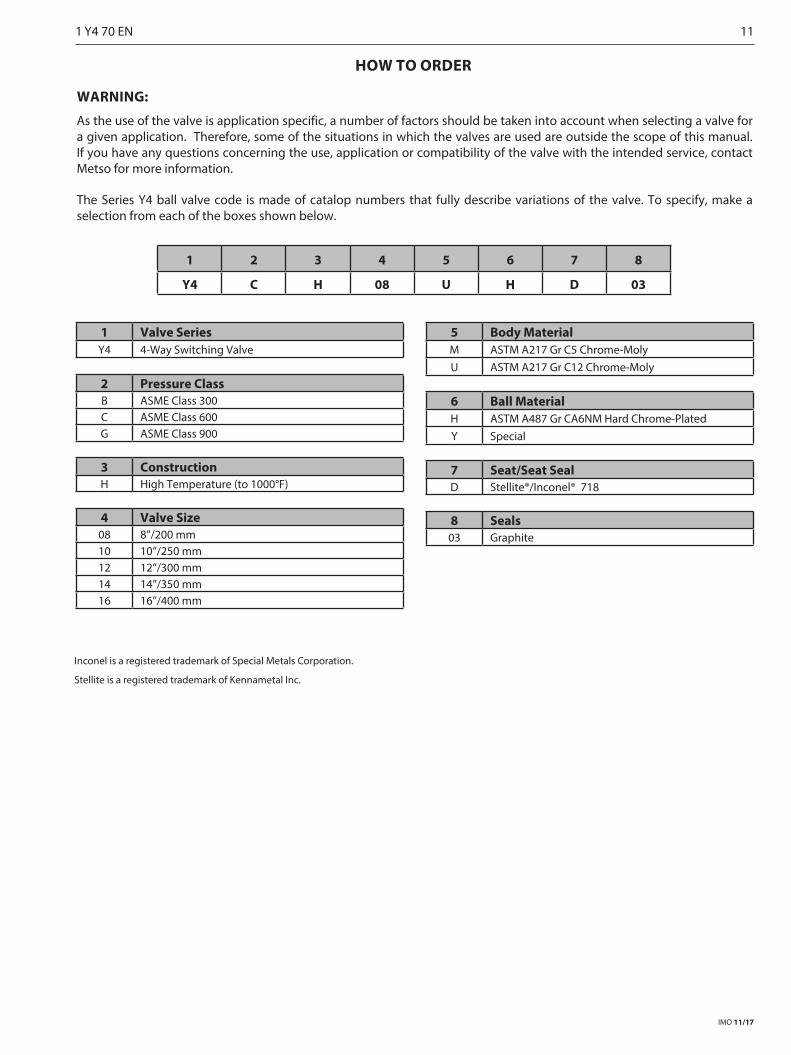
HOW TO ORDER
WARNING:
As the use of the valve is application specific, a number of factors should be taken into account when selecting a valve for a given application. Therefore, some of the situations in which the valves are used are outside the scope of this manual. If you have any questions concerning the use, application or compatibility of the valve with the intended service, contact Metso for more information.
The Series Y4 ball valve code is made of catalop numbers that fully describe variations of the valve. To specify, make a selection from each of the boxes shown below.
1 2 3 4 5 6 7 8
Y4 C H 08 U H D 03
1 Valve SeriesY4 4-Way Switching Valve
2 Pressure ClassB ASME Class 300C ASME Class 600G ASME Class 900
3 ConstructionH High Temperature (to 1000°F)
4 Valve Size08 8”/200 mm10 10”/250 mm12 12”/300 mm14 14”/350 mm16 16”/400 mm
5 Body MaterialM ASTM A217 Gr C5 Chrome-MolyU ASTM A217 Gr C12 Chrome-Moly
6 Ball MaterialH ASTM A487 Gr CA6NM Hard Chrome-PlatedY Special
7 Seat/Seat SealD Stellite®/Inconel® 718
8 Seals03 Graphite
Inconel is a registered trademark of Special Metals Corporation.
Stellite is a registered trademark of Kennametal Inc.
IMO 11/17
1 Y4 70 EN 11
Subject to change without prior notice.
Metso Flow Control Inc.
Europe, Vanha Porvoontie 229, P.O. Box 304, FI-01301 Vantaa, Finland. Tel. +358 20 483 150. Fax +358 20 483 151North America, 44 Bowditch Drive, P.O. Box 8044, Shrewsbury, M A 01545, USA. Tel. +1 508 852 0200. Fax +1 508 852 8172
South America, Av. Independéncia, 2500-Iporanga, 18087-101, Sorocaba-São Paulo, Brazil. Tel. +55 15 2102 9700. Fax +55 15 2102 9748 Asia Paci�c, 238B Thomson Road, #17-01 Novena Square Tower B, Singapore 307685. Tel. +65 6511 1011. Fax +65 6250 0830
China, 11/F, China Youth Plaza, No.19 North Rd of East 3rd Ring Rd, Chaoyang District, Beijing 100020, China. Tel. +86 10 6566 6600. Fax +86 10 6566 2583Middle East, Roundabout 8, Unit AB-07, P.O. Box 17175, Jebel Ali Freezone, Dubai, United Arab Emirates. Tel. +971 4 883 6974. Fax +971 4 883 6836
www.metso.com/valves
12 1 Y4 70 EN