defender 90 & 110 workshop maunual supplement
DESCRIPTION
Defender 90 & 110 Workshop Maunual SupplementTRANSCRIPT

GED DEFENDER 90 110 130
WORKSHOP MANUAL SUPPLEMENT
Publication Number SLR 621 E N WS 1
Published by the Technical Publications Department of
@ Copyright Land Rover 1990
Land Rover Lode Land
Sol ihul I West Midlands, 892 8NW
England

.
Section Number
01 INTRODUCTION :
CONTENTS
L
04
Page
GENERAL SPECIFICATION DATA
... . . . . . -.. ;,TI ,::-...$,. ...... ........ ,.. ,. ..... 'U . ..I-',
05 ENGINE TUNING DATA
- General information - Poisonous substances - Fuel Handling - Sealants - Disposal of oil and fluids - Abbreviations and symbols - Special tools - Vehicle identification numbers - Copyright
06 TORQUE WRENCH SETTING
- Tdi engine data - Fuel system - Cooling system - Clutch
L
12
9 - 1 2 9 9 9
ENGINE
109 I RECOMMENED LUBRICANTS, FLUIDS AND CAPACITIES
- Tdi engine lubricants - Capacities - Anti-freeze
17 - 18 17 - i a 17 - 18
- Camshaft - remove and refit - including front cover oil seals/timing belt and gears - Power steering pump bracket - remove and refit - Cylinder head - remove and refit - Camshaft timing belt - renew - Tdi engine - overhaul
30 31 32 34 35
19 1 FUEL SYSTEM
- Fuel injection pump - remove and refit - Air cleaner - remove and refit - ~ur-bo charger- remove and retit - Intercooler - remove and refit
-
81 84
86 a5
..:r :i' . . . , . ,. _,. - 5 . . ..
Section Number
I
30
Page
MANIFOLDS AND EXHAUST
26 I COOLING SYSTEM e .. -7
. . - 86 ELECTRICAL EQUIPMENT
- >
- Engine protection - Drain and refill - Fan cowl - remove and refit - Fan and coupling - remove and refit - Radiator - remove and refit - Water pump - remove and refit
87 87
88 89 90
a8
157 I STEERING
a DEFENDER INTRODUCTION
INTRODUCTION . I
This Workshop Manual Supplement is designed to assist skilled technicians in the efficient repair and maintenance of Land Rover vehicles.
01
Individuals who undertake their own repairs should have some skill and training, and limit repairs to components which could not affect t h e safety of t h e vehicle or its passengers. Any repairs required to safety critical items such as steering, brakes, o r suspension should be carried out by a Land Rover Dealer. Repairs t o such items should NEVER b e at tempted by untrained individuals.
WARNINGS and CAUTIONS are given throughout this Supplement in the following form:
WARNING: Procedures which must be followed precisely t o avoid the possibility of personal injury.
CAUTION: This calls attention t o procedures which must b e followed to avoid damage to components.
NOTE: This calls attention t o methods which make a job easier t o perform.
REFERENCES
References to the left or right hand side in the supplement are made when viewing the vehicle from the rear unless otherwise stated. With the engine and gearbox assembly removed, the water pump end of the engine is referred to as the front. To reduce repetition, some operations covered in this Manual d o not include reference to testing the vehicle after repair. It is essential that work is inspected and tested after completion and if necessary a road test of the vehicle is carried out particularly where safety related items are concerned.
-
DIMENSIONS
The dimensions quoted are to design engineering specification. Alternative unit equivalents, shown in brackets following the dimensions, have been converted from the original specification.
REPAIRS AND REPLACEMENTS
When replacement parts are required it is essential that genuine Land Rover parts are used. Attention is particularly drawn to the following points concerning repairs and the fitting of replacement parts and accessories: Safety features embodied in the vehicle may be impaired if other than Land Rover parts are fitted. In certain territories, legislation prohibits the fitting of parts not t o the vehicle manufacturer's specification. Torque wrench values given in the Workshop Manual supplement must be strictly adhered to. Locking devices, where specified, must be fitted. If the efficiency of a locking device is impaired during removal it must be replaced with a new one. Certain fasteners must not be re-used. These fasteners are specified in the Workshop Manual Supplement.
P O IS 0 N 0 US SUBSTANCES
Many liquids and other substances used in motor vehicles are poisonous and should under no circumstances be consumed and should be kept away from open wounds. These substances among others include anti-freeze, brake fluid, fuel, windscreen washer additives, air conditioning refrigerant, lubricants and various adhesives.
AS B EST0 S
WARNING: Some components on t h e vehicle, such as gaskets and friction surfaces (brake linings, clutch discs) may contain asbestos. inhaling asbestos dust is dangerous t o your health and the following essential precautions must be observed:
1 . Work out of doors or in a well ventilated area and wear a protective mask. 2. Dust found o n the vehicle or produced during work on the vehicle should be removed by vacuuming
3. Dust waste should be dampened, placed in a sealed container and marked to ensure safe disposal. 4. If any cutting, drilling etc., is attempted on materials containing asbestos the item should be dampened
and not by blowing.
and on1 hand tools or low speed power tools used.
1
101 I INTRODUCTION e DEFENDER
FUEL HANDLING PRECAUTIONS
The following information provides basic precautions which must be observed if fuel is t o b e handled safely. It also outlines the other areas of risk which must not be ignored. This information is issued for basic guidance only, and in any case of doubt, appropriate enquiries should be made of your local fire station.
Fuel vapour is highly flammable and in confined spaces is also very explosive and toxic. When fuel evaporates it produces 150 times its own volume in vapour, which when diluted with air becomes a readily ignitable mixture. The vapour is heavier than air and will always fall to the lowest level. It can readily be distributed throughout a workshop by air current, consequently, even a small spillage of fuel is very dangerous.
Always have a fire extinguisher containing F O A M CO or when dismantling fuel systems and in areas where fuel containers are stored.
GAS, or P O W D E R close at hand when handling fuel,
WARNING: It is imperative that the battery is not disconnected during fuel system repairs as arcing at the battery terminal could ignite fuel vapour in the atmosphere. Always disconnect the vehicle battery BEFORE carrying out work on a fuel system. Whenever fuel is being handled, transferred or stored, or when fuel systems are being dismantled all forms of ignition must be extinguished or removed, any head-lamps used must be flameproof and kept clear of spillage.
NO ONE S H O U L D BE PERMWrED TO REPAIR C O M P O N E N T S ASSOCIATED WITH FUEL WITHOUT FIRST HAVING H A D SPECIALIST TRAINING.
HOT FUEL H A N D L I N G
Before commencing any operation requiring fuel drainage from fuel tanks, the following procedures should be adhered to.
i 1. Allow sufficient time for the fuel t o cool, thus avoiding contact with hot fuels. 2. Vent system by removing the fuel cap in a well ventilated area. Replace cap until commencement of tank
drainage.
FUEL TRANSFER
WARNING: Fuel must not be extracted or drained from any vehicle while it is standing over a pit.
The transfer of fuel from the vehicle fuel tank must b e carried o u t in a well ventilated area. An approved transfer tank must be used according t o the transfer tank manufacturef s instructions and local regulations, including attention to grounding of tanks.
FUEL TANK REMOVAL
A fuel vapour label should b e attached to the fuel tank upon removal from the vehicle.
FUEL TANK REPAIR
p i. .. :’”
Under no circumstances should a repair to any tank b e attempted.
3
e DEFENDER INTRODUCTION 101
RECOMMENDED SEALANTS
A number of branded products are recommended in this Supplement for use during maintenance and repair work. These items include: HYLOMAR GASKET AND JOINTING COMPOUND and HYLOSIL R N SILICON COMPOUND. They should be available locally from garage equipment suppliers. If there is any problem obtaining supplies, contact one of the following companies for advice and the address of the nearest stockist.
<,, .
Marston Lubricants Limited Hylo House Cale Lane, New Springs Wigan, WN2 IJR
Tel: 0942 824242 Fax: 0942 826653 Telex: 67230
Northern Adhesives Limited Prudhoe Northumberland NE42 6NP
Tel: 0661 32014 Fax: 0661 35839
USED ENGINE OIL HANDLING PRECAUTIONS
- Prolonged and repeated contact with engine or motor oil will result in the removal of natural fats from the -skin, leading to dryness, irritation and dermatitis. In addition, used engine oil contains potentially harmful contaminants which may cause skin cancer. Adequate means of skin protection and washing facilities should be provided.
Health Protection Precautions
1. Avoid prolonged and repeated contact with oils, particularly used engine oils. 2. Wear protective clothing, including impervious gloves where applicable. 3. Do not put oily rags in pockets. 4. Avoid contaminating clothes, particularly underwear, with oil. 5. Overalls must be cleaned regularly. Discard unwashable clothing and oil impregnated footwear. 6 . First aid treatment must be obtained immediately for open cuts and wounds. 7. Use barrier creams, before each work period, to help the removal of oil from the skin. 8. Wash with soap and water to ensure all oil is removed (skin cleansers and nail brushes will help).
Preparations containing lanolin replace the natural skin oils which have been removed. 9. DO not use petrol, kerosene, diesel fuel, gas oil, thinners or solvents for washing the skin.
10. I f skin disorders develop, obtain medical advice. 11. Where practicable, degrease components prior t o handling. 12. Where there is a risk of eye contact, eye protection should be worn, for example, goggles or face
shields; in addition an eye wash facility should be provided.
.
DISPOSING OF USED OILS AND FLUIDS
Environmental protection precaution
It is illegal to pour used oil and other fluids onto the ground, down sewers o r drains, or into waterways.
Dispose of used oil through authorised waste disposal contractors.
S P E CI FICATIO N
Purchasers are advised that the specification details set out in this Supplement apply to a range of vehicles and not to any one. For the specification of a particular vehicle, purchasers should contact their Dealer. The Manufacturers resetve the right t o vary their specifications with or without notice, and at such times and in such manner as they think fit. Major as well as minor changes may be involved in accordance with the Manufacturer's policy of constant product improvement.
While every effort is made to ensure the accuracy of the particulars contained in this Supplement, neither the Manufacturer or Dealer, by whom this Supplement is supplied, shall in any circumstances be held liable for any inaccuracy or the consequences thereof.
. .
3
01
COPYRIGHT
INTRODUCTION e DEFENDER
Q Rover Group Ltd 1990
All rights reserved. N o part of this publication may be produced, stored in a retrieval system or transmitted in any form, electronic, mechanical, photocopying, recording or other means without prior written permission of Rover Group Ltd.
SPECIAL SERVICE TOOLS
The use of approved special service tools is important. They are essential if service operations are to be carried out efficiently, and safely. Where the use of special service tools i specified, only these tools should be used to avoid the possibility of personal injury or damage to components.
ACCESSORIES AND CONVERSIONS
Land Rover vehicles are designed and constructed for a variety of uses but no alterations or conversions should be carried out to any vehicle produced by Land Rover which could affect the safety of the vehicle or its passengers.
T
Land Rover has tested and approved a large number of accessories and conversions, suitable for this vehicle. Before fitting any accessory o r commencing any conversion work to any Land Rover vehicle, CHECK that the accessory o r conversion is approved by Land Rover.
WARNING: DO NOT FIT unapproved accessories o r conversions, as they could affect the safety of the vehicle. Land Rover will not accept any liability for death, personal injury or damage to property which may occur as a direct result of fitment of non-approved accessories or the carrying out of non-approved conversions to Land Rover vehicles.
4

DEFENDER INTRODUCTION n 01
, - ABBREVIATIONS A N D SYMBOLS ' .. . .- . a:.; ,;.:
I: .I .:..,*-:. '
Across flats (bolt size) .......................................... AF Low tension .......................................................... 1.t. After bottom dead centre .............................. ABDC After top dead centre ..................................... ATDC Alternating current .............................................. a.c.
Ampere hour ................................................. amp hr Before bottom dead centre ............................ BBDC Before top dead centre ................................... BTDC Bottom dead centre ......................................... BDC
British Standards ................................................... BS Carbon monoxide .............................................. C O Centimetre .......................................................... cm Centigrade (Celsuis) .............................................. C Cubic centimetre ................................................ cm3 Cubic inch ............................................................ in3 Degree (angle) ........................................... deg or O
Diameter ............................................................. dia. Direct current ..................................................... d.c. Electronic Control Unit ................................... E.C.U. Electronic Fuel Injection ................................... E.F.I. Fahrenheit ............................................................... F Feet ....................................................................... ft
Fifth ..................................................................... 5th First ...................................................................... 1st Fluid ounce ....................................................... f l oz Foot pounds (torque) ........................................ ft Ib Fourth .................................................................. 4th Gramme (force) g f Gramme (mass) g Gallons gal Gallons (US) .................................................. US gal High tension (electrical) .................................... H.T.
Ampere amp ..............................................................
............................................ Brake horse power bhP
%
1 . . . Degree (temperature) ................................. deg or O . . .:,
Feet per minute ............................................... ft/min
.....................................................
...................................................... ................................................................
Internal diameter ................................................ I.D. ,I . . . . . .. Inches of mercury .......................................... in. Hg . . Inches .................................................................... in
. . . . . . . .
.............................................. Kilogramme (force) kg f Kilogramme (mass.) kg .............................................. Kilogramme centimetre (torque) ................... kgf.cm Kilogramme per square millimetre ............... kgf/mm2 Kilogramme per square centimetre .............. kgf/cm2 Kilogramme metres (torque) ........................... kgf.m Kilometres ........................................................... km Kilometres per hour ......................................... km/h Kilovolts ................................................................ kV Left-hand steering .......................................... LHStg Left-hand thread ............................................ LHThd Litres ................................................................... litre
Maximum ......................................................... m a . Metre ..................................................................... m Millilitre ................................................................ mi Millimetre ........................................................... mm Miles per gallon ................................................. mpg Miles per hour ................................................... mPh Minute (angle) ......................................................... ' Minus (of tolerance) ............................................... - Negative (electrical) ................................................ - Newton meters (torque) .................................... Nm Number .............................................................. No. Ohms ............................................................... ohm Ounces (force) .................................................... ozf Ounces (mass) ...................................................... oz Ounce inch (torque) ...................................... ozf.in. Outside diameter ............................................. O.D. Part number ................................................. Part N o . Percentage ............................................................ % Pints Pt Pints (US) ........................................................ US pt Plus (tolerance) ..................................................... + Positive (electrical) ................................................ + Pound (force) ....................................................... Ibf Pounds inch (torque) ...................................... in.lbf. Pound (mass) ......................................................... Ib Pounds per square inch .................................... P.S.I.
Reference ........................................................... ref. Revolution per minute ..................................... r.p.m Right-hand ........................................................... RH
Second (numerical order) ................................... 2nd Specific gravity ................................................ sp.gr. Square centimetres ............................................. cm2 Square inches ....................................................... in2 Standard wire gauge ....................................... s . w . ~ . Synchroniser/Synchromesh ......................... synchro.
Top dead centre ................................................ TDC United Kingdom .................................................. UK Vehicle Identification Number ............................ VIN Volts ...................................................................... v Watts .................................................................... W
.....................................................................
Ratio ........................................................................ :
Second (angle) ....................................................... I'
Third ................................................................... 3rd
SCREW T H READS American Standard Taper Pipe .......................... NPTF British Standard Pipe ........................................... BSP Unified Coarse ................................................. UNC Unified Fine ....................................................... U N F
5
loll INTRODUCTION e DEFENDER
Special Service Tools The use of approved special service tools is important. They are essential if service operations are t o be carried out efficiently, and safely. Where special tools are specificed, only these tools should be used to avoid the possibility of personal injury or damage to the components. Also the amount of time which they save can be considerable.
Every special tool is designed with the close co-operation of Land Rover, and n o tools is put into production which has not been tested and approved by us. New tools are only introduced where an operation cannot be satisfactorily carried out using existing tools or standard equipment. The user is therefore assured that the tool is necessary and that it wilt perform accurately, efficiently and safely.
Special tools bulletins will be issued periodically giving details of new tools as they are introduced.
All orders and enquiries from the United Kingdom should be sent direct to V. L. Churchill. Overseas orders should be placed with the local V. L. Churchill distributor, where one exists. Countries where there is no distributor may order direct from V. L. Churchill Limited, PO Box 3, Daventry, Northants, England, N N I 1 4 N F .
The tools recommended in this Workshop Manual Supplement are listed in a multi-language illustrated catalogue obtainable from Messers. V. L. Churchill at the above address under publication number VLC 23721187 or from Land Rover Merchandising Service, quoting publication number SMR 681 MI, PO Box 534, Erdington, Birmingham, 624 OQ5.
6
.. ~.,.. .. .I ). . b: : .., .. ... ,. ... .. . . . ..
.
DEFENDER LOCATION OF VEHICLE IDENTIFICATION & UNIT NUMBERS 101
VEHICLE IDENTIFICATION NUMBER (VIN)
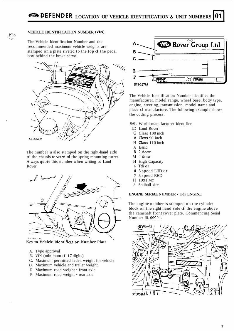
The Vehicle Identification Number and the recommended maximum vehicle weights are stamped on a plate riveted to the top of the pedal box behind the brake servo
The number is also stamped on the right-hand side of the chassis forward of the spring mounting turret. Always quote this number when writing to Land Rover.
Key to Veh \
iicle ldentiiication Number Plate
A. Type approval B. VIN (minimum of 17 digits) C. Maximum permitted laden weight for vehicle D. Maximum vehicle and trailer weight E. Maximum road weight - front axle F. Maximum road weight - rear axle
E F PAINT 0 TRIM
ST3067M
The Vehicle Identification Number identifies the manufacturer, model range, wheel base, body type, engine, steering, transmission, model name and place of manufacture. The following example shows the coding process.
SAL World manufacturer identifier LD Land Rover C Class 100 inch V Class 90 inch H Class 110 inch A Basic B 2 d o o r
M 4 d o o r H High Capacity F Tdi o r 8 5 speed LHD o r 7 5 speed RHD H 1991 MY A Solihull site
ENGINE SERIAL NUMBER - Tdi ENGINE
The engine number is stamped o n the cylinder block on the right hand side of the engine above the camshaft front cover plate. Commencing Serial Number IIL 00001.
..
7
L
01 LOCATION OF VEHICLE IDENTIFICATION & UNIT NUMBERS e DEFENDER
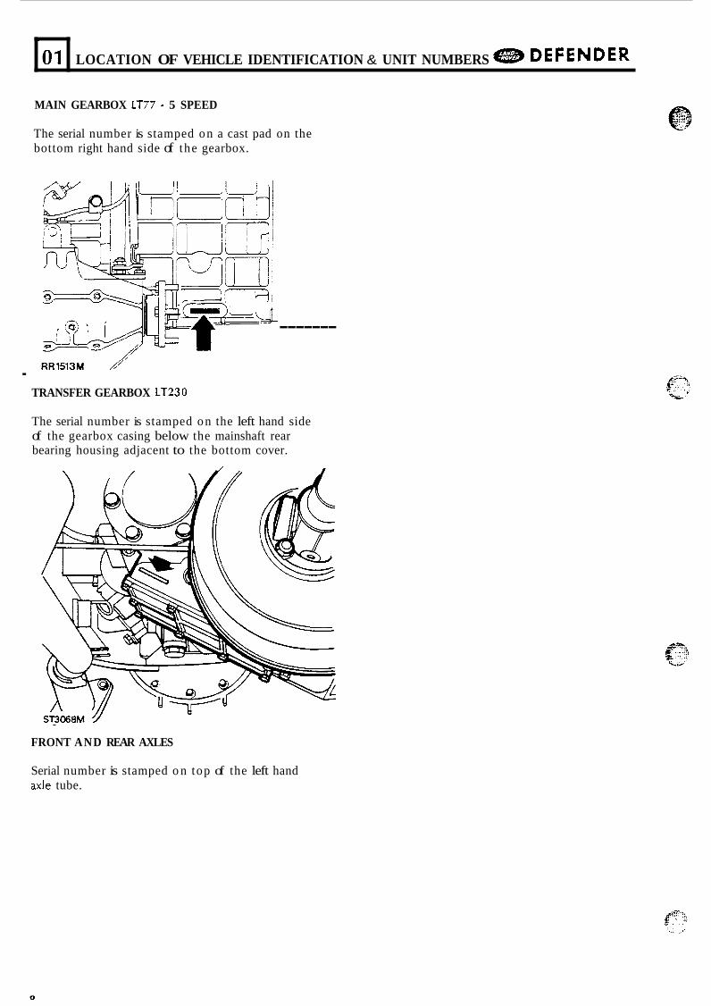
MAIN GEARBOX LT77 - 5 SPEED
The serial number is stamped on a cast pad on the bottom right hand side of the gearbox.
RR1513M 1' . TRANSFER GEARBOX LT230
-------
The serial number is stamped on the left hand side of the gearbox casing below the mainshaft rear bearing housing adjacent to the bottom cover.
FRONT AND REAR AXLES
Serial number is stamped o n top of the left hand axle tube.
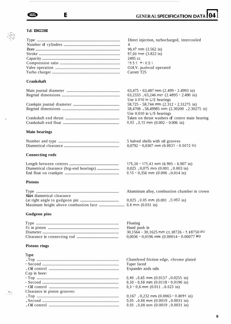
n e DEFENDER GENERAL SPECIFICATION DATA I04 I Tdi ENGINE
Type ................................................................................. Direct injection, turbocharged, intercooled Number of cylinders ......................................................... 4 Bore .................................................................................. 90,47 mm (3.562 in) Stroke ............................................................................... 97,OO mm (3.822 in) Capacity ............................................................................ 2495 cc Compression ratio ............................................................ 19.5:l + - 0.5:l Valve operation ................................................................ O.H.V. pushrod operated Turbo charger ................................................................... Carrett T25
Crankshaft
Main journal diameter ...................................................... 63,475 - 63,487 mm (2.499 - 2.4993 in) Regrind dimensions .......................................................... 63,2333 . 63,246 mm (2.4895 - 2.490 in)
Regrind dimensions .......................................................... 58,4708 . 58,49985 mm (2.30200 . 2.30275 in)
Crankshaft end thrust ....................................................... Taken on thrust washers of centre main bearing Crankshaft end float ......................................................... 0,05 . 0,15 mm (0.002 - 0.006 in)
Use 0.010'in U/S bearings Crankpin journal diameter ................................................ 58,725 - 58,744 mm (2.312 - 2.31275 in)
Use 0.010 in U/S bearings 1
Main bearings
Number and type ............................................................. 5 halved shells with oil grooves Diametrical clearance ........................................................ 0,0792 - 0,0307 mm (0.0031 - 0.0012 in)
Connecting rods
Length between centres ................................................... 175,38 - 175,43 mm (6.905 - 6.907 in) Diametrical clearance (big-end bearings) .......................... 0,025 . 0,075 mm (0.001 . 0.003 in) End float on crankpin ....................................................... 0,15 - 0,356 mm (0.006 . 0.01 4 in)
Pistons
Type ................................................................................. Aluminium alloy, combustion chamber in crown Skirt diametrical clearance
Maximum height above combustion face ........................ 0,8 mm (0.031 in)
Gudgeon pins
(at right angle to gudgeon pin ......................................... 0,025 . 0,05 mm (0.001 . 0.002 in)
Type ................................................................................. Floating Fit in piston ...................................................................... Hand push in Diameter ........................................................................... 30,1564 - 30,1625 mm (1.1 8726 - 7 .1 8750 in) Clearance in connecting rod ............................................ 0,0036 - 0,0196 mm (0.00014 - 0.00077 in)
Pistons rings
Type . Top ................................................................................ Chamfered friction edge, chrome plated
. Oil control ..................................................................... Expander ands rails - Second ........................................................................... Taper faced
Cap in bore: - Top ................................................................................ 0,40 . 0,65 mm (0.0157 . 0.0255 in) - Second ........................................................................... 0,30 - 0,50 mm (0.0118 - 0.0196 in) - Oil control ..................................................................... 0,3 - 0,6 mm (0.011 . 0.023 in) Clearance in piston grooves: . Top ................................................................................ 0,167 . 0,232 mm (0.0065 - 0.0091 in) . Second ........................................................................... 0,05 . 0,08 mm (0.0019 . 0.0031 in) . Oil control ..................................................................... 0,05 . 0,08 mm (0.0019 . 0.0031 in)
-:. :.,a: i.
I : , '
9
04
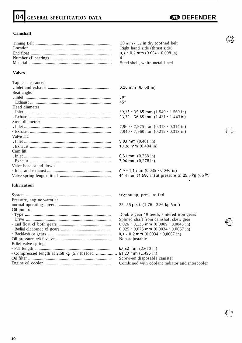
Camshaft
GENERAL SPECIFICATION DATA e DEFENDER
Timing Belt ....................................................................... Location ........................................................................... End float ........................................................................... Number of bearings ......................................................... Material ............................................................................
Valves
Tappet clearance: . Inlet and exhaust ............................................................ Seat angle: . Inlet ................................................................................ - Exhaust ........................................................................... Head diameter: . Inlet ................................................................................ . Exhaust ........................................................................... Stem diameter: - . Inlet ................................................................................ - Exhaust ........................................................................... Valve lift: . Inlet ................................................................................ . Exhaust ........................................................................... Cam lift . Inlet ................................................................................ . Exhaust ........................................................................... Valve head stand down - Inlet and exhaust ............................................................ Valve spring length fitted .................................................
lubrication
System .............................................................................. Pressure, engine warm at normal operating speeds .................................................. Oil pump: - Type ............................................................................... - Drive .............................................................................. - End float of both gears .................................................. - Radial clearance of gears ................................................ - Backlash or gears ........................................................... Oil pressure relief valve .................................................... Relief valve spring: - Full length ...................................................................... - Compressed length at 2.58 kg (5.7 Ib) load .................. Oil filter ............................................................................ Engine oil cooler ..............................................................
30 mm (1.2 in dry toothed belt Right hand side (thrust side) 0, l - 0,2 mm (0.004 - 0.008 in) 4 Steel shell, white metal lined
0,20 mm (0.008 in)
30" 45 O
39,35 - 39,65 mm (1.549 - 1.560 in) 36,35 - 36,65 mm (1.431 - 1.443 in)
7,960 - 7,975 mm (0.313 - 0.314 in) 7,940 - 7,960 mm (0.212 - 0.313 in)
9,93 mm (0.401 in) 10,26 mm (0.404 in)
6,81 mm (0.268 in) 7,06 mm (0,278 in)
0,9 - 1,l mm (0.035 - 0.040 in) 40,4 mm (1.590 in) at pressure of 29.5 kg (65 Ib) . Wet sump, pressure fed
25- 55 p.s.i. (1.76 - 3.86 kgf/cm2)
Double gear 10 teeth, sintered iron gears Splined shaft from camshaft skew gear 0,026 - 0,135 mm (0.0009 - 0.0045 in) 0,025 - 0,075 mm (0,0034 - 0.0067 in) 0, l - 0,2 mm (0.0034 - 0,0067 in) Non-adjustable
67,82 mm (2.670 in) 61,23 mm (2.450 in) Screw-on disposable canister Combined with coolant radiator and intercooler
...... (-?$ ........ .. .- . .-
10
48B DEFENDER GENERAL SPECIFICATION DATA n 04
<.., 3 i..- ........ '- "' 5,. . I .... . . , ..*:;,:; ...... .... ~.,. ._. ,
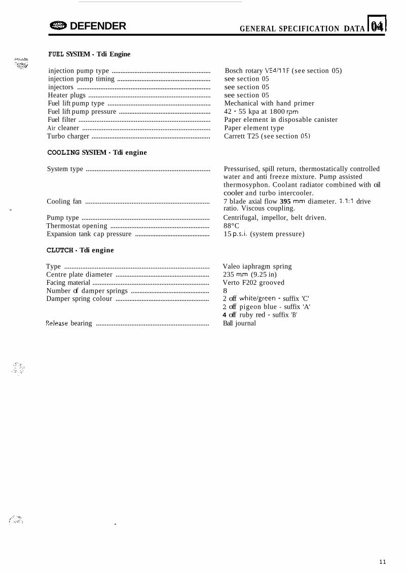
FUEL SYSTEM - Tdi Engine
injection pump type ......................................................... Bosch rotary VE4/11 F (see section 05) injection pump timing ...................................................... see section 05 injectors ........................................................................... see section 05 Heater plugs ..................................................................... see section 05 Fuel lift pump type ........................................................... Mechanical with hand primer Fuel lift pump pressure ..................................................... 42 - 55 kpa at 1800 rpm Fuel filter .......................................................................... Paper element in disposable canister Air cleaner ........................................................................ Paper element type Turbo charger ................................................................... Carrett T25 (see section 05)
COOLING SYSTEM - Tdi engine
System type ...................................................................... Pressurised, spill return, thermostatically controlled water and anti freeze mixture. Pump assisted thermosyphon. Coolant radiator combined with oil cooler and turbo intercooler.
Cooling fan ...................................................................... 7 blade axial flow 395 mm diameter. 1.1:l drive
Pump type ........................................................................ Centrifugal, impellor, belt driven. Thermostat opening ......................................................... 88°C Expansion tank cap pressure ............................................ 15 p.s.i. (system pressure)
% ratio. Viscous coupling.
CLUTCH - Tdi engine
Type ................................................................................. Valeo iaphragm spring Centre plate diameter ...................................................... 235 mm (9.25 in) Facing material .................................................................. Verto F202 grooved Number of damper springs .............................................. 8 Damper spring colour ...................................................... 2 off white/green - suffix 'C'
2 off pigeon blue - suffix 'A' 4 off ruby red - suffix 'B'
Eelease bearing ................................................................ Ball journal
11

p. .-.. : .!:. .d . ..I
e DEFENDER ENGINE TUNING DATA 105
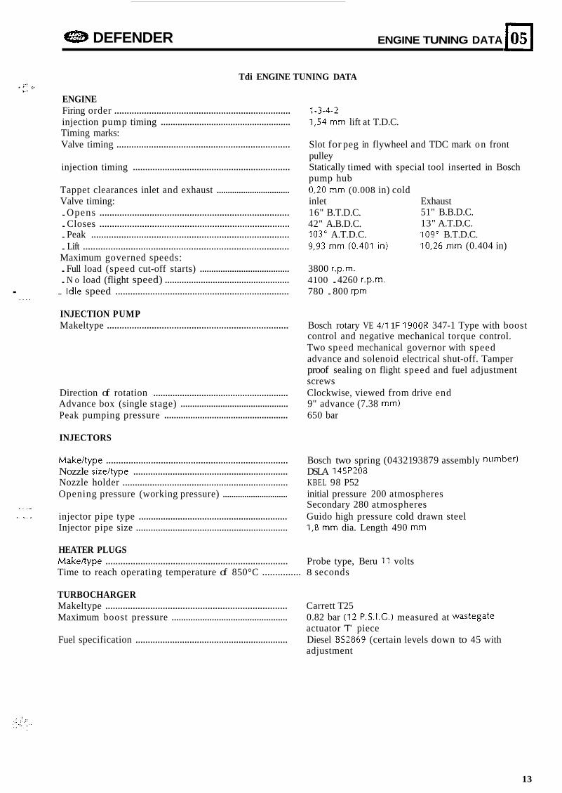
Tdi ENGINE TUNING DATA . i-. 3
1..
ENGINE Firing order ....................................................................... 1-3-4-2 injection pump timing ...................................................... 1,54 mm lift at T.D.C. Timing marks: Valve timing ...................................................................... Slot for peg in flywheel and TDC mark on front
injection timing ................................................................ Statically timed with special tool inserted in Bosch
Tappet clearances inlet and exhaust ................................. 0,20 mm (0.008 in) cold Valve timing: inlet Exhaust . Opens ............................................................................ 16" B.T.D.C. . Closes ............................................................................ 42" A.B.D.C. . Peak ............................................................................... 103" A.T.D.C. 109" B.T.D.C. . Lift .................................................................................. 9,93 mm (0.401 in) Maximum governed speeds:
pulley
pump hub
51" B.B.D.C. 13" A.T.D.C.
10,26 mm (0.404 in)
. Full load (speed cut-off starts) ....................................... 3800 r.p.m.
. N o load (flight speed) .................................................... 4100 . 4260 r.p.m. .. Idle speed ...................................................................... 780 . 800 rpm .
. . . .
INJECTION PUMP Makeltype ......................................................................... Bosch rotary VE 411 1 F 1900R 347-1 Type with boost
control and negative mechanical torque control. Two speed mechanical governor with speed advance and solenoid electrical shut-off. Tamper proof sealing on flight speed and fuel adjustment screws
Direction of rotation ........................................................ Clockwise, viewed from drive end Advance box (single stage) .............................................. 9" advance (7.38 mm) Peak pumping pressure .................................................... 650 bar
INJECTORS
Makeltype ......................................................................... Bosch two spring (04321 93879 assembly number) Nozzle sizeltype ............................................................... DSLA 145P208 Nozzle holder ................................................................... KBEL 98 P52 Opening pressure (working pressure) .............................. initial pressure 200 atmospheres
Secondary 280 atmospheres injector pipe type ............................................................. Guido high pressure cold drawn steel Injector pipe size .............................................................. 1,8 mm dia. Length 490 mm
. . . . ,. I. . .. , . ,
HEATER PLUGS Makeltype ......................................................................... Probe type, Beru 11 volts Time to reach operating temperature of 850°C ............... 8 seconds
TURBOCHARGER Makeltype ......................................................................... Carrett T25 Maximum boost pressure ................................................. 0.82 bar (12 P.S.I.C.) measured at wastegate
Fuel specification .............................................................. Diesel 852869 (certain levels down to 45 with actuator 'T' piece
adjustment
13

.
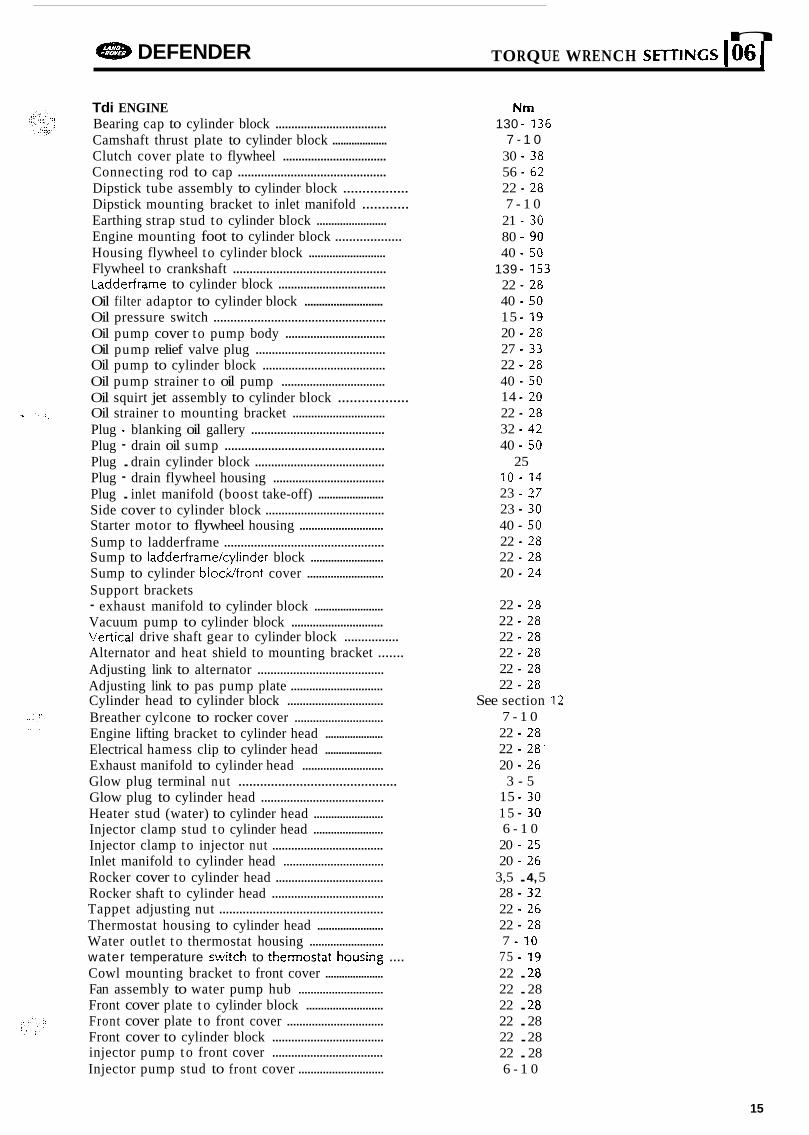
n e DEFENDER TORQUE WRENCH SE~TINGS 106 I Tdi ENGINE Bearing cap to cylinder block ................................... Camshaft thrust plate to cylinder block .................... Clutch cover plate to flywheel ................................. Connecting rod to cap ............................................. Dipstick tube assembly to cylinder block ................. Dipstick mounting bracket to inlet manifold ............ Earthing strap stud to cylinder block ........................ Engine mounting foot to cylinder block ................... Housing flywheel to cylinder block .......................... Flywheel to crankshaft ..............................................
Oil filter adaptor to cylinder block ........................... Oil pressure switch ................................................... Oil pump cover to pump body ................................ Oil pump relief valve plug ........................................ Oil pump to cylinder block ...................................... Oil pump strainer t o oil pump ................................. Oil squirt jet assembly to cylinder block ..................
Plug - blanking oil gallery ......................................... Plug - drain oil sump ................................................ Plug . drain cylinder block ........................................ Plug - drain flywheel housing ................................... Plug . inlet manifold (boost take-off) ....................... Side cover to cylinder block .....................................
Sump to ladderframe ................................................
Ladderframe to cylinder block ..................................
* Oil strainer to mounting bracket ..............................
Starter motor to flywheel housing ............................
Sump to ladderframekylinder block ......................... Sump to cylinder blocUfront cover .......................... Support brackets - exhaust manifold to cylinder block ........................ Vacuum pump to cylinder block .............................. Vertical drive shaft gear to cylinder block ................ Alternator and heat shield to mounting bracket .......
Cylinder head to cylinder block ...............................
Adjusting link to alternator ....................................... Adjusting link to pas pump plate ..............................
Breather cylcone to rocker cover ............................. Engine lifting bracket to cylinder head ..................... Electrical hamess clip to cylinder head ..................... Exhaust manifold to cylinder head ........................... Glow plug terminal nut ............................................ Glow plug to cylinder head ...................................... Heater stud (water) to cylinder head ........................ Injector clamp stud t o cylinder head ........................ Injector clamp to injector nut ................................... Inlet manifold to cylinder head ................................ Rocker cover to cylinder head .................................. Rocker shaft to cylinder head ................................... Tappet adjusting nut ................................................. Thermostat housing to cylinder head ....................... Water outlet t o thermostat housing .........................
Cowl mounting bracket to front cover ..................... Fan assembly to water pump hub ............................ Front cover plate t o cylinder block .......................... Front cover plate t o front cover ............................... Front cover to cylinder block ...................................
Injector pump stud to front cover ............................
water temperature switch to thermestat heusing ....
injector pump to front cover ...................................
Nm 130 .136
7 - 1 0 30 .38 56 .62 22 .28 7 - 1 0
21 .30 80 .90 40 .50
139 .153 22 . 2 8 40 .50 15 .19 20 .28 27 .33 22 . 2 8 40 .50 14 .20 22 . 2 8 32 .42 40 .50
25 10 .14 23 .27 23 .30 40 .50 22 . 2 8 22 .28 20 .24
22 . 2 8 22 . 2 8 22 . 2 8 22 . 2 8 22 .28 22 . 2 8
See section 12 7 - 1 0 22 . 2 8 22 . 2 8 ' 20 .26
3 - 5 15 .30 1 5 . 3 0 6 - 1 0 20 .25 20 .26
3, 5 . 4, 5 28 .32 22 .26 22 .28 7 .10
75 . 7 3
22 . 28 22 . 28
22 . 28 22 . 28 22 . 28 22 . 28 6 - 1 0
15
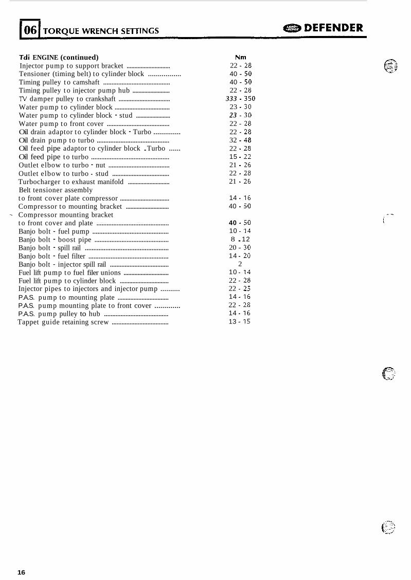
Tdi ENGINE (continued) Injector pump to support bracket ............................ Tensioner (timing belt) to cylinder block ................. Timing pulley t o camshaft ........................................ Timing pulley t o injector pump hub ......................... lV damper pulley t o crankshaft ................................ Water pump t o cylinder block .................................. Water pump to cylinder block - stud ....................... Water pump t o front cover ...................................... Oil drain adaptor t o cylinder block - Turbo .............. Oil drain pump to turbo ...........................................
Oil feed pipe t o turbo .............................................. Outlet elbow t o turbo - nut ..................................... Outlet elbow to turbo - stud ................................... Turbocharger t o exhaust manifold ........................... Belt tensioner assembly t o front cover plate compressor ............................... Compressor t o mounting bracket ............................
t o front cover and plate ........................................... Banjo bolt - fuel pump ............................................. Banjo bolt - boost pipe ............................................ Banjo bolt - spill rail ................................................. Banjo bolt - fuel filter ............................................... Banjo bolt - injector spill rail .................................... Fuel lift pump t o fuel filer unions ............................. Fuel lift pump t o cylinder block ...............................
P.A.S. pump to mounting plate ................................ P.A.S. pump mounting plate to front cover ............. P.A.S. pump pulley to hub ....................................... Tappet guide retaining screw ...................................
Oil feed pipe adaptor to cylinder block . Turbo ......
- Compressor mounting bracket
Injector pipes to injectors and injector pump ..........
Nm 22 . 2 8 40 . 5 0 40 .50 22 . 2 8
333 . 3 5 0 23 . 3 0 23 . 3 0 22 .28 22 .28 32 . 4 8 22 .28 15 . 22 21 .26 22 .28 21 .26
14 . 16 40 . 5 0
40 . 50 10 .14 8 . 12 20 .30 14 . 20
2 10 . 14 22 . 2 8 22 .25 14 . 16 22 . 2 8 14 . 16 13 . 15
(!?: .... ..... ::
. Y ..... &.~
...% i
16
e DEFENDER
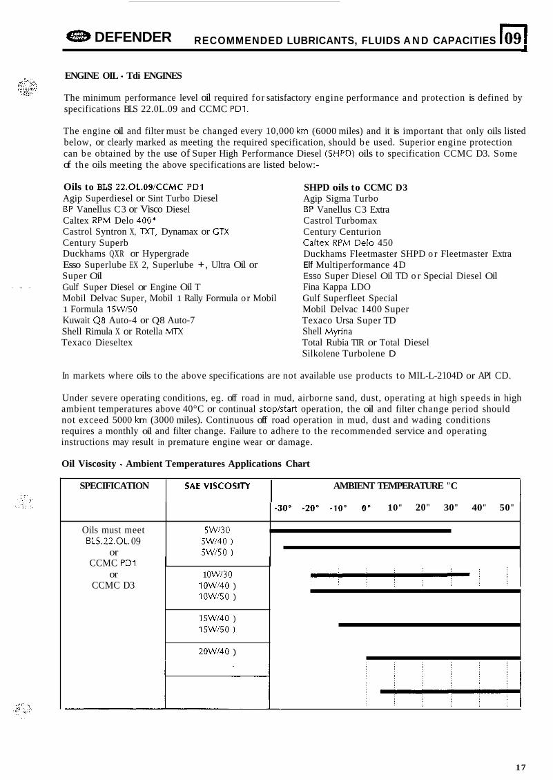
Oils must meet BLS.22.OL. 09
or
RECOMMENDED LUBRICANTS, FLUIDS A N D CAPACITIES 109 I
-30" -20" -10" 0" 10" 20" 30" 40" 50"
5Wf30 I
5Wi40 ) 5Wt50 1
.<- - ENGINE OIL - Tdi ENGINES
The minimum performance level oil required for satisfactory engine performance and protection is defined by specifications BLS 22.0L.09 and CCMC PD1.
. .,.. .~ ,:;- ;:.!! , ..~._ ,....,. 81'1 . ,.. ..
,w>;:.
CCMC PD1 or
CCMC D3
The engine oil and filter must be changed every 10,000 km (6000 miles) and it is important that only oils listed below, or clearly marked as meeting the required specification, should be used. Superior engine protection can be obtained by the use of Super High Performance Diesel (SHPD) oils to specification CCMC D3. Some of the oils meeting the above specifications are listed below:-
1 Owl30 10Wi40 ) 10W150 )
15Wl40 ) 15Wt50 )
20Wf40 )
- + -
Oils to BLS 22.OL.09tCCMC PD1 Agip Superdiesel or Sint Turbo Diesel BP Vanellus C3 or Visco Diesel Caltex RPM Delo 400* Castrol Syntron X, TXT, Dynamax or GTX Century Superb Duckhams QXR or Hypergrade Esso Superlube EX 2, Superlube +, Ultra Oil or Super Oil Gulf Super Diesel or Engine Oil T Mobil Delvac Super, Mobil 1 Rally Formula or Mobil 1 Formula 15Wl50 Kuwait Q8 Auto-4 or Q8 Auto-7 Shell Rimula X or Rotella MTX Texaco Dieseltex
SHPD oils to CCMC D3 Agip Sigma Turbo BP Vanellus C3 Extra Castrol Turbomax Century Centurion Caltex RPM Delo 450 Duckhams Fleetmaster SHPD o r Fleetmaster Extra Elf Multiperformance 4D Esso Super Diesel Oil TD o r Special Diesel Oil Fina Kappa LDO Gulf Superfleet Special Mobil Delvac 1400 Super Texaco Ursa Super TD Shell Myrina Total Rubia TIR or Total Diesel Silkolene Turbolene D
In markets where oils to the above specifications are not available use products t o MIL-L-2104D or API CD.
Under severe operating conditions, eg. off road in mud, airborne sand, dust, operating at high speeds in high ambient temperatures above 40°C or continual stoptstart operation, the oil and filter change period should not exceed 5000 km (3000 miles). Continuous off road operation in mud, dust and wading conditions requires a monthly oil and filter change. Failure to adhere to the recommended service and operating instructions may result in premature engine wear or damage.
Oil Viscosity - Ambient Temperatures Applications Chart
I AMBIENT TEMPERATURE "C I !jAE v'scos'Ty I SPECIFICATION
17
CAPACITIES
The following capacity figures are approximate and are provided as a guide only. All oil levels must be set using the dipstick or level plugs as applicable.
Engine sump oil ................................................................ 6,OO litres (10.56 pints)
Transfer box oil ................................................................ 2,30 litres (4 pints) Cooling system ................................................................ 11,lO litres (20 pints)
Extra when filling following new filter .............................. 0,85 litres (1.50 pints)
Anti-freeze
Ethylene Glycol based anti-freeze (containing n o methanol) with non-phosphate corrosion inhibitors only are suitable for use in Tdi engines t o ensure protection of the cooling system against frost and corrosion. N o inhibitors should be used. Only anti-freeze, summer and winter even in climates where anti-freeze is not necessary.
O n e part anti-freeze, one part water, i.e. 50% anti-freeze in coolant. Complete protection below -36°C.
~ See cooling system section 26 for engine protection information.
18
e DEFENDER ENGINE 11 2 I
... .. I., ;:,:;i
1’ . . - ... , . . . . , ,
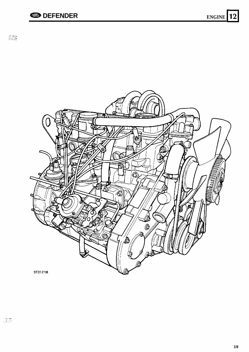
ST3121 M
~I .,.. :, ... . . . . . . ..._ .. .
19
12 ENGINE e DEFENDER _I
CLUTCH AND FLYWHEEL HOUSING
LAND ROVER Tdi engine COMPONENTS ST3066M -
I . Clutch housing 2. Bell housing stud (9) 3. Starter motor stud (1) 4. Allen bolts (4) 5. Plug (2) 6. Screw housing to block (6) 7. Washer (6) 8. Bolt housing to block (2) 9. Spring washer ( 2 )
10. Bracket ( 2 ) 11. Harness clip ( 2 ) 12. Oil seal 13. Flywheel 14. Starter ring 15. Reinforcing plate 16. Bolt flywheel t o crank 17. Clutch cover 18. Clutch plate 19. Dowel 20. Screw 21. Spring washer
$"'! ... ..,
-->"d
2n

.
DEFENDER ENGINE 12
3
ST3066M
21
12
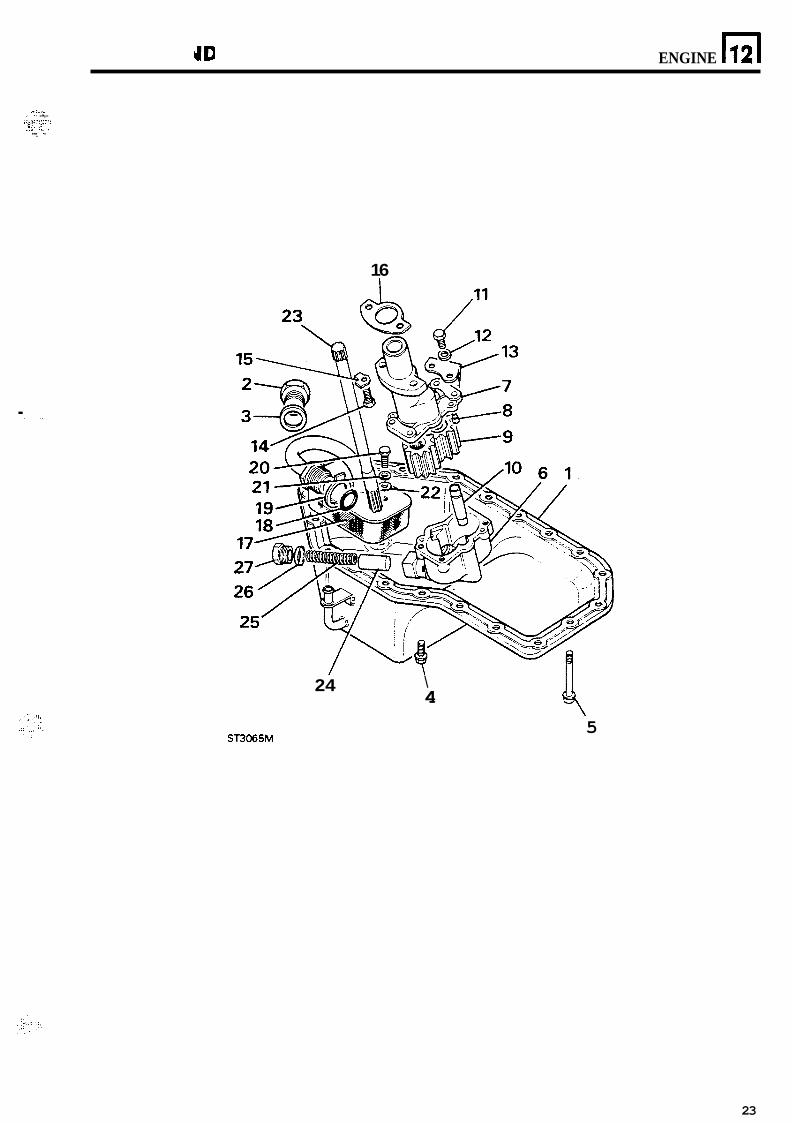
SUMP AND OIL PUMP COMPONENTS ST3065M - LAND ROVER Tdi engine
ENGINE DEFENDER
1. Sump 2. Drain plug 3. Joint washer 4. Flange bolt M8x20 (8) 5. Flange bolt M8x60 (1 2) 6. Oil pump housing lower 7. Oil pump housing upper 8. Dowel 9. Oil pump gears
10. Spindle 11. Screw 12. Spring washer 13. Support bracket 14. Screw 15. Lock washer 16. Casket 17. Filter 18. 0 ring 19. Lock washer 20. Screw 21. Spring washer 22. Plain washer 23. Drive shaft 24. Oil relief plunger 25. Spring 26. Joint washer 27. Oil relief plug
22
-DEFENDER ENGINE n 12
.-:.:. < ,. . . ,.. ,+ ' . : ,,.,x2.;:,, , I . .. ,1: . , ~ . .._ .. ... .
16
. . ,
24
ST3065M
\ 4 4
5
23
e DEFENDER
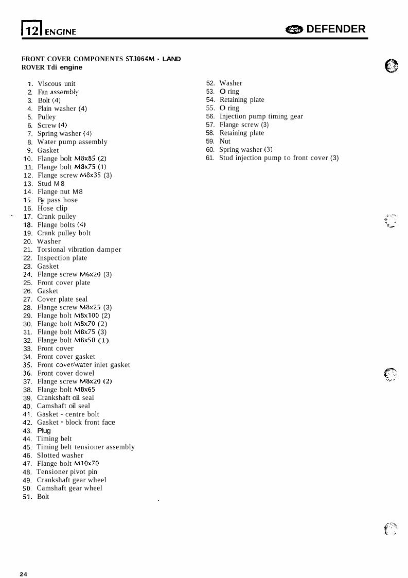
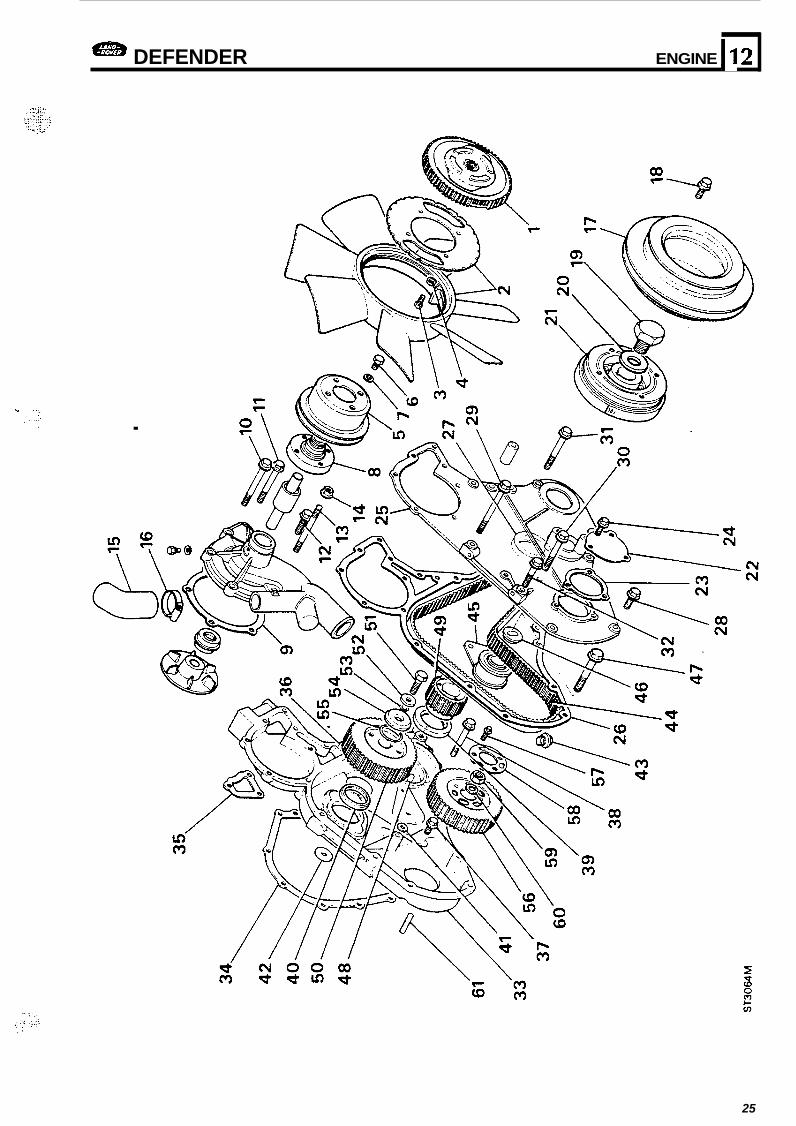
FRONT COVER COMPONENTS ST3064M - LAND ROVER Tdi engine
1. 2. 3. 4. 5. 6. 7. 8. 9.
10. 11. 12. 13. 14. 15. 16. - 17. 7 8. 19. 20. 21. 22. 23. 24. 25. 26. 27. 28. 29. 30. 31. 32. 33. 34. 35. 36. 37. 38. 39. 40. 41. 42. 43. 44. 45. 46. 47. 48. 49. 50. 51.
Viscous unit Fan assemb!y Bolt (4) Plain washer (4) Pulley Screw (4) Spring washer (4) Water pump assembly Gasket Flange bolt M8x85 (2) Flange bolt M8x75 (1) Flange screw M8x35 (3) Stud M 8 Flange nut M8 By pass hose Hose clip Crank pulley Flange bolts (4) Crank pulley bolt Washer Torsional vibration damper Inspection plate Gasket Flange screw M6x20 (3) Front cover plate Gasket Cover plate seal Flange screw M8x25 (3) Flange bolt M8x100 (2) Flange bolt M8x70 (2) Flange bolt M8x75 (3) Flange bolt M8x50 (1) Front cover Front cover gasket Front covedwater inlet gasket Front cover dowel Flange screw M8x20 (2) Flange bolt M8x65 Crankshaft oil seal Camshaft oil seal Gasket - centre bolt Gasket - block front face
Timing belt Timing belt tensioner assembly Slotted washer Flange bolt M10x70 Tensioner pivot pin Crankshaft gear wheel Camshaft gear wheel Bolt
Plug
52. Washer 53. 0 ring 54. Retaining plate 55. 0 ring 56. Injection pump timing gear 57. Flange screw (3) 58. Retaining plate 59. Nut 60. Spring washer (3) 61. Stud injection pump t o front cover (3)
24
DEFENDER ENGINE 11 2
.
25
12
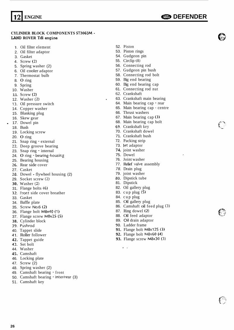
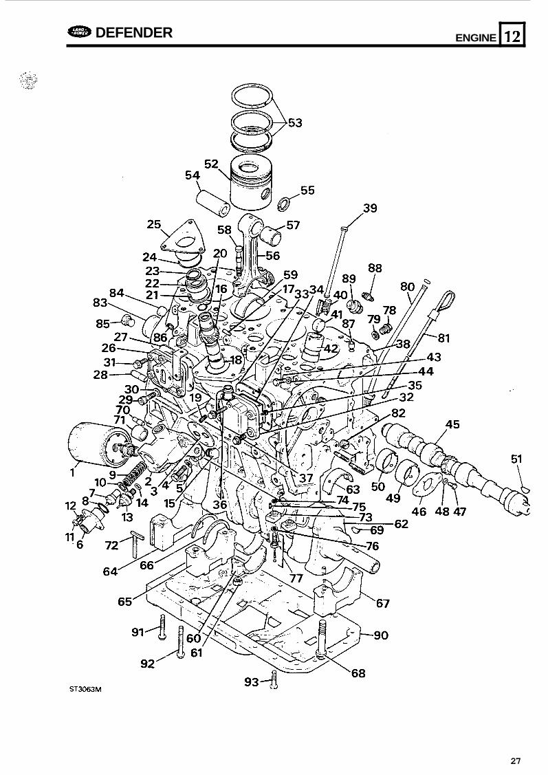
CYLINDER BLOCK COMPONENTS ST3063M - LAND ROVER Tdi engine
ENGINE a DEFENDER
1. 2. 3. 4. 5. 6. 7. 8. 9.
10. 11. 12. 13. 14. 15. 16. . 17. 18. 19. 20. 21. 22. 23. 24. 25. 26. 27. 28. 29. 30. 31. 32. 33. 34. 35. 36. 37. 38. 39. 40. 41. 42. 43. 44. 45. 46. 47. 48. 49. 50. 51.
Oil filter element Oil filter adaptor Gasket Screw (2) Spring washer (2) Oil cooler adaptor Thermostat bulb 0 ring Spring Washer Screw (2) Washer (2) Oil pressure switch Copper washer Blanking plug Skew gear Dowel pin Bush Locking screw 0 ring Snap ring - external Deep groove bearing Snap ring - internal 0 ring - bearinghousifig Bearing housing Rear side cover Casket Dowel - flywheel housing (2) Socket screw (2) Washer (2) Flange bolts (6) Froct side cover breather Gasket Baffle plate Screw No.6 (2) Flange bolt M8x40 (1) Flange screw M8x25 (5) Cylinder block Pushrod Tappet slide Roller follower Tappet guide Set bolt Washer Camshaft Locking plate Screw (2) Spring washer (2) Camshaft bearing - front Camshaft bearing - interhear (3) Camshaft key
52. Piston 53. Piston rings 54. Gudgeon pin 55. Circlip (8) 56. Connecting rod 57. Gudgeon pin bush 58. Connecting rod bolt 59. Big end bearing 60. Big end bearing cap 61. Connecting rod nut 62. Crankshaft
. 63. Crankshaft main bearing 64. Main bearing cap - rear 65. Main bearing cap - centre 66. Thrust washers 67. Main bearing cap (3) 68. Main bearing cap bolt 69. Crankshaft key 70. Crankshaft dowel 71. Crankshaft bush 72. Packing strip 73. let adaptor 74. joint washer 75. Dowel 76. Joint washer 77. Relief vaive assembly 78. Drain plug 79. joint washer 80. Dipstick tube 81. Dipstick 82. Oil gallery plug 83. c u p plug (5) 84. c u p plug 85. Oil gallery plug 86. Camshaft oil feed plug (3) 87. Ring dowel (2) 88. Oil feed adaptor 89. Oil drain adaptor 90. Ladder frame 91. Flange bolt M8x125 (3) 92. Flange bolt M8x60 (4) 93. Flange screw M8x30 (3)
- .
0 I. .. .. .
26
ENGINE e DEFENDER
ST3063M
-
12
27
12
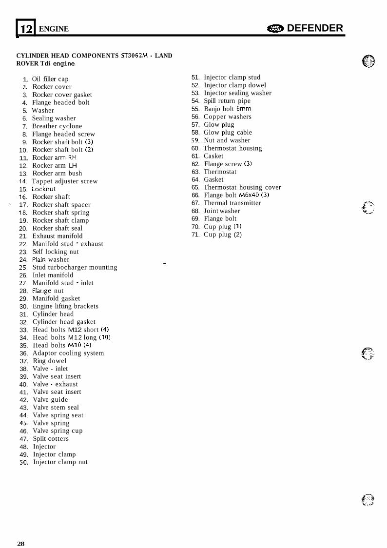
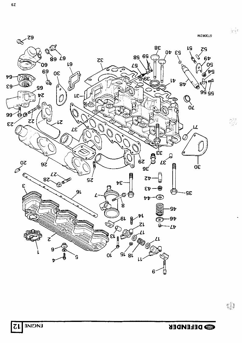
CYLINDER HEAD COMPONENTS ST3062M - LAND ROVER Tdi engine
ENGINE e DEFENDER
1.
3. 4. 5. 6. 7. 8. 9.
10. 11. 12. 13. 14. 15. 16. - 17. 18. 19. 20. 21. 22. 23. 24. 25. 26. 27. 28. 29. 30. 31. 32. 33. 34. 35. 36. 37. 38. 39. 40. 41. 42. 43. 44. 45. 46. 47. 48. 49. 50.
3 -.
Y
Oil filler cap Rocker cover Rocker cover gasket Flange headed bolt Washer Sealing washer Breather cyclone Flange headed screw Rocker shaft bolt (3) Rocker shaft bolt (2) Rocker arm RH Rocker arm LH Rocker arm bush Tappet adjuster screw Locknut Rocker shaft Rocker shaft spacer Rocker shaft spring Rocker shaft clamp Rocker shaft seal Exhaust manifold Manifold stud - exhaust Self locking nut Plair; washer Stud turbocharger mounting Inlet manifold Manifold stud - inlet Flarlge nut Manifold gasket Engine lifting brackets Cylinder head Cylinder head gasket Head bolts M12 short (4) Head bolts M12 long (10) Head bolts M10 (4) Adaptor cooling system Ring dowel Valve - inlet Valve seat insert Valve - exhaust Valve seat insert Valve guide Valve stem seal Valve spring seat Valve spring Valve spring cup Split cotters Injector Injector clamp Injector clamp nut
51. Injector clamp stud 52. Injector clamp dowel 53. Injector sealing washer 54. Spill return pipe 55. Banjo bolt 6mm 56. Copper washers 57. Glow plug 58. Glow plug cable 59. Nut and washer 60. Thermostat housing 61. Casket 62. Flange screw (3) 63. Thermostat 64. Gasket 65. Thermostat housing cover 66. Flange bolt M6x40 (3) 67. Thermal transmitter 68. Joint washer 69. Flange bolt 70. Cup plug (1) 71. Cup plug (2)
28
6Z
c
121 ENGINE a DEFENDER
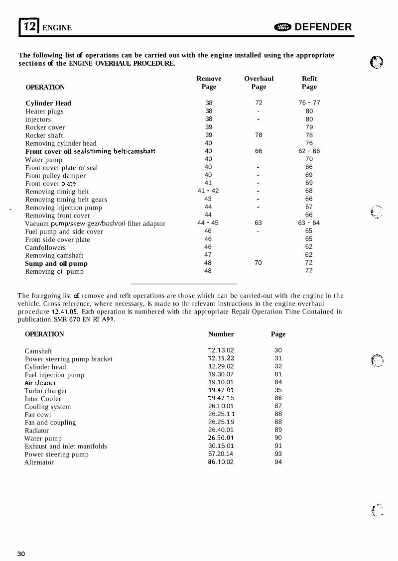
The following list of operations can be carried out with the engine installed using the appropriate sections of the ENGINE OVERHAUL PROCEDURE.
OPERATION
Cylinder Head Heater plugs injectors Rocker cover Rocker shaft Removing cylinder head Front cover oil seals/timing beltlcamshaft Water pump Front cover plate or seal Front pulley damper Front cover plate Removing timing belt Removing timing belt gears Removing injection pump Removing front cover Vacuum pump/skew gear/bush/oil filter adaptor Fuel pump and side cover Front side cover plate Cam followers Removing camshaft Sump and oil pump Removing oil pump
Remove Overhaul Refit Page Page Page
38 38 38 39 39 40 40 40 40 40 41
41 - 42 43 44 44
44 - 45 46 46 46 47 48 48
72
78
66
63
70
76 - 77 80 80 79 78 76
62 - 66 70 66 69 69 68 66 67 66
65 65 62 62 72 72
63 - 64
The foregoing list of remove and refit operations are those which can be carried-out with the engine in the vehicle. Cross reference, where necessary, is made to thr relevant instructions in the engine overhaul procedure 12.41.05. Each operation is numbered with the appropriate Repair Operation Time Contained in publication SMR 670 EN RT A91.
OPERATION Number Page
Cams haft Power steering pump bracket Cylinder head Fuel injection pump Air cleaner Turbo charger Inter Cooler Cooling system Fan cowl Fan and coupling Radiator Water pump Exhaust and inlet manifolds Power steering pump Altemator
12.1 3.02 72.35.22 12.29.02 19.30.07 19.10.01 19.42.01 19.42.1 5 26.1 0.01 26.25.1 1 26.25.1 9 26.40.01 26.50.01 30.1 5.01 57.20.14 86.1 0.02
30 31 32 81 84 35 86 87 88 88 89 90 91 93 94
30
.:' ?: , i .,. .!.-. ..... .
+_I._ - : . . U .. . . .,..
e DEFENDER ENGINE 12
CAMSHAFT
Service Repair No. 12.13.02.
Remove and refit
1. Remove the bonnet and disconnect the battery.
2. Disconnect the radiator bottom hose and allow the coolant t o drain and reconnect the hose.
3. Remove the radiator top coolant hose, 4. Remove the fan and viscous coupling
assembly, see operation 26.25.1 9. instructions 4 to 7.
5. Remove the fan cowl. 6. Remove the radiator, see operation 26.40.01.
7. Remove the air cleaner, see operation instructions 3 to 5 and 7 to 8.
19.1 0.01. instructions 1 to 5.
instruction 5 to 9.
bracket, see operation 12.25.22 instructions 4 t o 9.
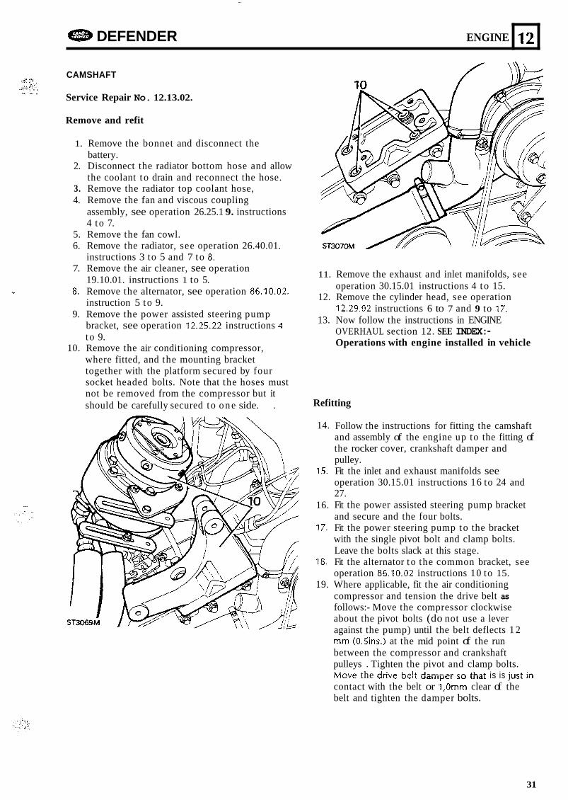
where fitted, and the mounting bracket together with the platform secured by four socket headed bolts. Note that the hoses must not be removed from the compressor but it should be carefully secured to o n e side. .
- 8. Remove the alternator, see operation 86.10.02.
9. Remove the power assisted steering pump
10. Remove the air conditioning compressor,
...
11. Remove the exhaust and inlet manifolds, see operation 30.15.01 instructions 4 to 15.
12. Remove the cylinder head, see operation 12.29.02 instructions 6 to 7 and 9 to 17.
13. Now follow the instructions in ENGINE OVERHAUL section 12. SEE INDEX:- Operations with engine installed in vehicle
Refitting
14.
15.
16.
17.
18.
19.
Follow the instructions for fitting the camshaft and assembly of the engine up to the fitting of the rocker cover, crankshaft damper and pulley. Fit the inlet and exhaust manifolds see operation 30.15.01 instructions 16 to 24 and 27. Fit the power assisted steering pump bracket and secure and the four bolts. Fit the power steering pump to the bracket with the single pivot bolt and clamp bolts. Leave the bolts slack at this stage. Fit the alternator t o the common bracket, see operation 86,10.02 instructions 10 to 15. Where applicable, fit the air conditioning compressor and tension the drive belt as follows:- Move the compressor clockwise about the pivot bolts (do not use a lever against the pump) until the belt deflects 1 2 mm (0.5ins.I at the mid point of the run between the compressor and crankshaft pulleys . Tighten the pivot and clamp bolts. M m e the drive belt dampei so that is is jiisi iii contact with the belt or 1,Omm clear of the belt and tighten the damper bolts.
31

L
12
20. Fit and tension the power steering pump drive belt, see operation 57.20.14 instruction 10. Take note of the CAUTION when tensioning the belt.
21. Fit the air clemer, s ee operation 19.10.01 instructions 12 to 14.
22. Fit the radiator, see operation 26.40.01
ENGINE a DEFENDER
POWER STEERING PUMP BRACKET
Service Repair No. 12.25.22
Remove and refit
1. Disconnect the battery. 2. Remove the air cleaner, see operation
19.1 0.01. 3. Remove the alternator, instructions 2 t o 9
operation 86.1 0.02. 4. Remove the steering pump two adjustment
clamp bolts and remove the drive belt. 5. Remove the single pivot bolt.
\\ I I c
\y 4 ST3026M
instructions 9 to 15. 23. Fit the fan cowl in position but d o not secure
to the radiator. retaining bolts. 24. Fit the fan and coupling assembly, see
operation 26.25.19 instructions 8 to 11. 25. Fill the cooling system, see operation 26.10.01
instructions 5 to 8.
6 . Move the pump aside with the two hoses still attached to gain access to the bracket four
7. Remove the single long bolt through the
8. Remove the single bolt frpm the front into the cylinder block into the bracket.
cylinder block.
Continued
32
DEFENDER ENGINE 11 2
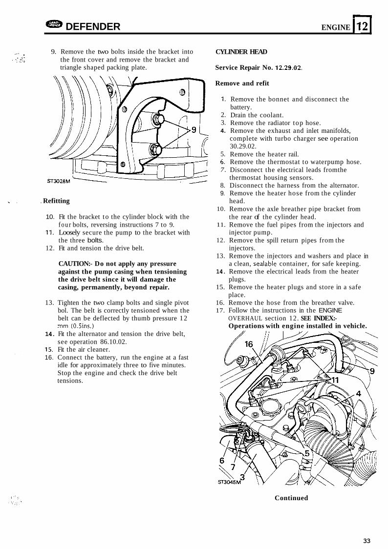
I- . 9. Remove the two bolts inside the bracket into the front cover and remove the bracket and triangle shaped packing plate.
. -. ~ I .I,
. J
- . . Refitting
10.
11.
12.
13.
14.
15. 16.
I .
Fit the bracket t o the cylinder block with the four bolts, reversing instructions 7 to 9. Loosely secure the pump to the bracket with the three bolts. Fit and tension the drive belt.
CAUTION:- Do not apply any pressure against the pump casing when tensioning the drive belt since it will damage the casing, permanently, beyond repair.
Tighten the two clamp bolts and single pivot bol. The belt is correctly tensioned when the belt can be deflected by thumb pressure 12 mm (0.5ins.) Fit the alternator and tension the drive belt, see operation 86.10.02. Fit the air cleaner. Connect the battery, run the engine at a fast idle for approximately three to five minutes. Stop the engine and check the drive belt tensions.
CYLINDER HEAD
Service Repair No. 12.29.02.
Remove and refit
1.
2. 3. 4.
5. 6. 7.
8. 9.
10.
11.
12.
13.
14.
15.
16. 17.
Remove the bonnet and disconnect the battery. Drain the coolant. Remove the radiator top hose. Remove the exhaust and inlet manifolds, complete with turbo charger see operation 30.29.02. Remove the heater rail. Remove the thermostat to waterpump hose. Disconnect the electrical leads fromthe thermostat housing sensors. Disconnect the harness from the alternator. Remove the heater hose from the cylinder head. Remove the axle breather pipe bracket from the rear of the cylinder head. Remove the fuel pipes from the injectors and injector pump. Remove the spill return pipes from the injectors. Remove the injectors and washers and place in a clean, sealable container, for safe keeping. Remove the electrical leads from the heater
Remove the heater plugs and store in a safe place. Remove the hose from the breather valve. Follow the instructions in the ENGINE OVERHAUL section 12. SEE INDEX:- Operations with engine installed in vehicle.
plugs.
Continued
33
121 ENGINE a DEFENDER _I
Refitting
18. Follow the instructions in ENGINE OVERHAUL from "fitting cylinder head" and continue until the rocker cover is fitted.
19. Fit the heater plugs and connect the electrical leads. Do not allow any part of the lead or insulation to touch the cylinder head when fitted.
20. Fit the injectors - see ENGINE OVERHAUL. 21. Fit the spill retum pipes to the injectors. 22. Fit the supply pipes to the injectors and pump. 23. Fit the hose to the breather valve. 24. Fit the axle breather bracket. 25. Fit the heater hose to cylinder head. 26. Connect the hamess to the altemator. 27. Fit the waterpump t o thermostat hose. 28. Connect the leads t o the thermostat sensors. 29. Fit the inlet and exhaust manifolds and heater - rail. 30. Fit the radiator top hose. 31. Fill the cooling system, see operation 26.10.01. 32. Fit the bonnet.
f-; .... . .., .' .
34
DEFENDER ENGINE n 12 . . I
m I
CAMSHAfl TIMING BELT
Service Repair No. 12.65.18
Renew
1. Disconnect the battery. 2. Remove the fan and viscous coupling
assembly, see operation 26.25.19. 3. Slacken and remove the power steering pump
drive belt, see operation 57.20.14. 4. Slacken and remove the air conditioning
compressor drive belt. 5. Remove the air conditioning compressor from
the mounting bracket but d o not detach the fluid hoses from the compressor. Move the compressor aside taking care not t o strain the
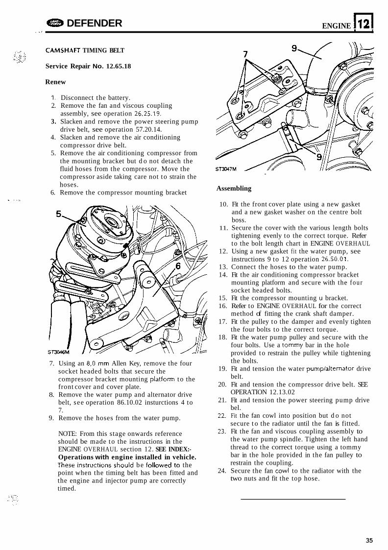
Assembling hoses. 6. Remove the compressor mounting bracket
- ,
7. Using an 8 ,O mm Allen Key, remove the four socket headed bolts that secure the compressor bracket mounting platform to the front cover and cover plate.
8. Remove the water pump and alternator drive belt, see operation 86.10.02 insturctions 4 to 7.
9. Remove the hoses from the water pump.
NOTE: From this stage onwards reference should be made to the instructions in the ENGINE OVERHAUL section 12. SEE INDEX:- Operations with engine installed in vehicle. These imtructi~ns shnu!d be !c!lcwed the point when the timing belt has been fitted and the engine and injector pump are correctly timed.
10. Fit the front cover plate using a new gasket and a new gasket washer on the centre bolt boss.
11. Secure the cover with the various length bolts tightening evenly to the correct torque. Refer to the bolt length chart in ENGINE OVERHAUL
12. Using a new gasket fit the water pump, see instructions 9 to 12 operation 26.50.01.
13. Connect the hoses to the water pump. 14. Fit the air conditioning compressor bracket
mounting platform and secure with the fou r socket headed bolts.
15. Fit the compressor mounting U bracket. 16. Refer to ENGINE OVERHAUL for the correct
method of fitting the crank shaft damper. 17. Fit the pulley to the damper and evenly tighten
the four bolts to the correct torque. 18. Fit the water pump pulley and secure with the
four bolts. Use a tommy bar in the hole provided to restrain the pulley while tightening the bolts.
19. Fit and tension the water pump/alternator drive belt.
20. Fit and tension the compressor drive belt. SEE OPERATION 12.13.02
21. Fit and tension the power steering pump drive bel.
22. Fit the fan cowl into position but d o not secure t o the radiator until the fan is fitted.
23. Fit the fan and viscous coupling assembly to the water pump spindle. Tighten the left hand thread to the correct torque using a tommy bar in the hole provided in the fan pulley to restrain the coupling.
24. Secure the fan cowl to the radiator with the two nuts and fit the top hose.
35
12 ENGINE DEFENDER J
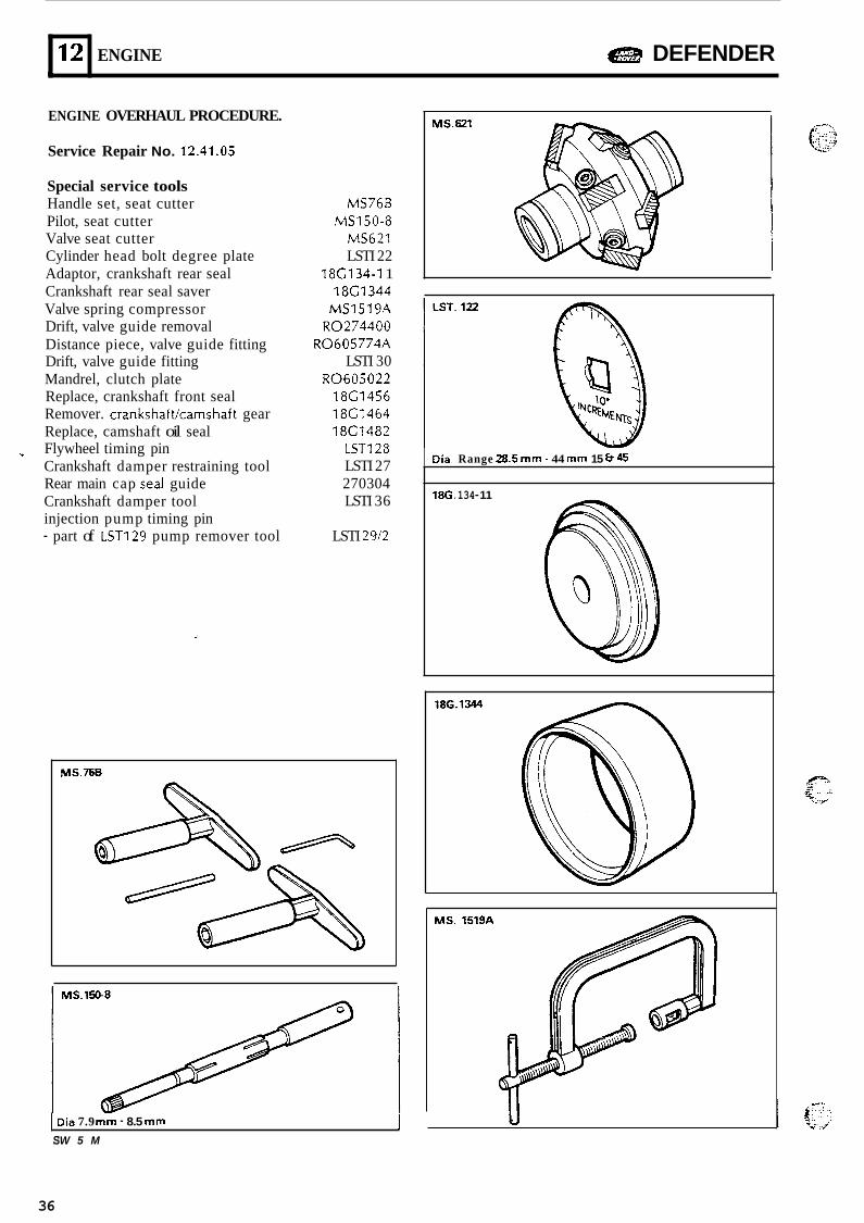
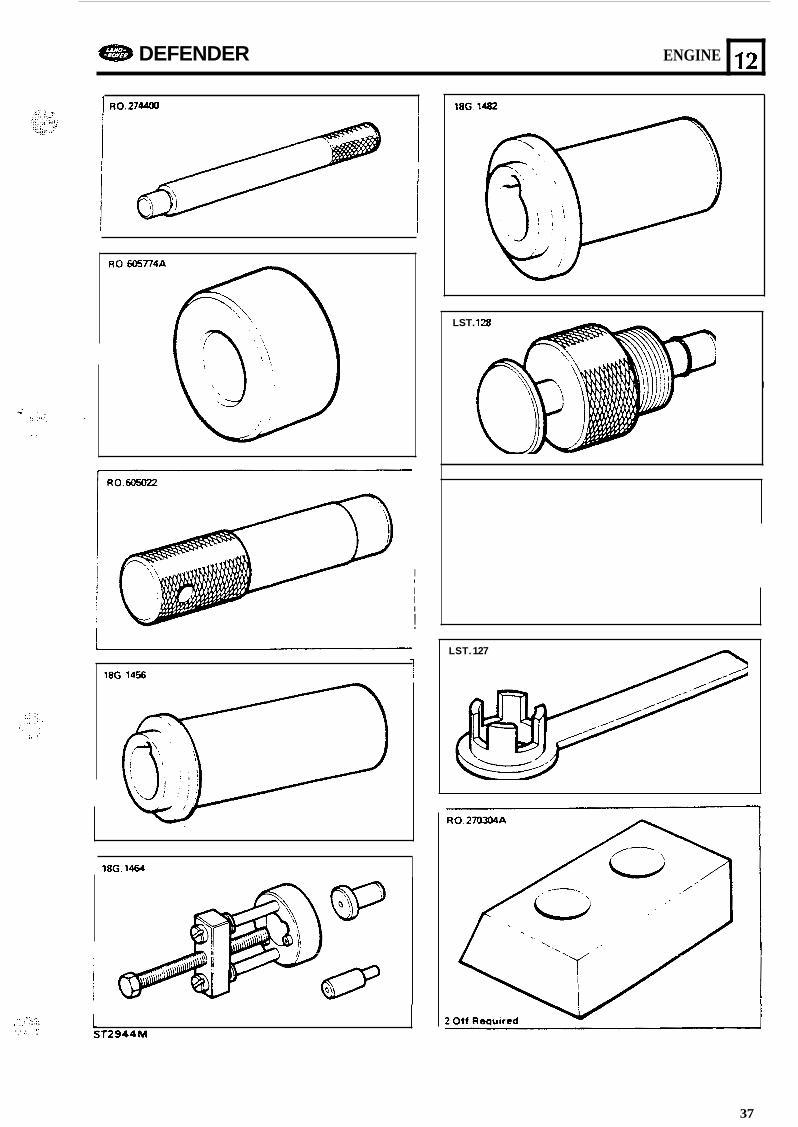
ENGINE OVERHAUL PROCEDURE.
Service Repair No. 12.41.05
Special service tools Handle set, seat cutter Pilot, seat cutter Valve seat cutter Cylinder head bolt degree plate Adaptor, crankshaft rear seal Crankshaft rear seal saver Valve spring compressor Drift, valve guide removal Distance piece, valve guide fitting Drift, valve guide fitting Mandrel, clutch plate Replace, crankshaft front seal Remover. crankshaftkamshaft gear Replace, camshaft oil seal
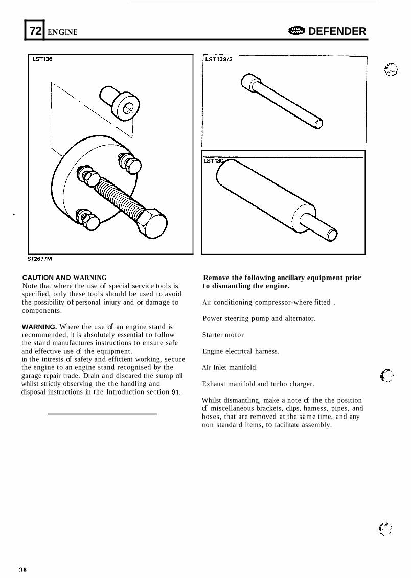
Crankshaft damper restraining tool Rear main cap sea1 guide Crankshaft damper tool injection pump timing pin - part of LST129 pump remover tool
_1 Flywheel timing pin
MS76B
MS621 LSTI 22
18C1344 MS1519A
R0274400 R0605774A
LSTI 30 R0605022
18C1456 18C1464 18C1482
LSTl28 LSTI 27 270304 LSTI 36
LSTI 2912
MS150-8
18G134-I 1
MS.768
Dia 7.9 mm - 8.5 mm 1 S W 5 M
~
Die. Range 28.5” - 44 mm 15 b 45
18G. 134- 11
186.1344
-@ MS. 1519A
11
36
e DEFENDER ENGINE
1 R0.27-
12
I I I I I
!
LST. 128
18G 1456 1
I
18G. 1464
., ,:_:i ::..: , . . . . . . ..
I
ST2344M 1
1BG. 1482
LST. 127
37
72
LST136
ENGINE DEFENDER
ST2677M
CAUTION AND WARNING Note that where the use of special service tools is specified, only these tools should be used to avoid the possibility of personal injury and or damage to components.
WARNING. Where the use of an engine stand is recommended, it is absolutely essential t o follow the stand manufactures instructions to ensure safe and effective use of the equipment. in the intrests of safety and efficient working, secure the engine to an engine stand recognised by the garage repair trade. Drain and discared the sump oil whilst strictly observing the the handling and disposal instructions in the Introduction section 01.
Remove the following ancillary equipment prior t o dismantling the engine.
Air conditioning compressor-where fitted .
Power steering pump and alternator.
Starter motor
Engine electrical harness.
Air Inlet manifold.
Exhaust manifold and turbo charger.
Whilst dismantling, make a note of the the position of miscellaneous brackets, clips, hamess, pipes, and hoses, that are removed at the same time, and any non standard items, to facilitate assembly.
DEFENDER ENGINE
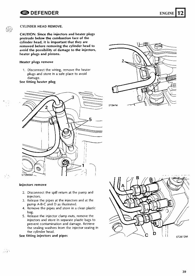
CYLINDER HEAD REMOVE.
12
. . ._... . I . . . - . I ..
39
121 ENGINE a DEFENDER
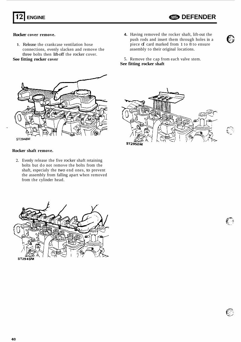
Rocker cover remove. 4. Having removed the rocker shaft, lift-out the push rods and insert them through holes in a piece of card marked from 1 t o 8 to ensure assembly t o their original locations.
5. Remove the cap from each valve stem.
1. Release the crankcase ventilation hose connections, evenly slacken and remove the three bolts then lift-off the rocker cover.
See fitting rocker cover See fitting rocker shaft
ST2948M
Rocker shaft remove.
2. Evenly release the five rocker shaft retaining bolts but d o not remove the bolts from the shaft, especialy the two end ones, to prevent the assembly from falling apart when removed from the cylinder head.
ST294CM
40
. .I ., .,.. " ..
e DEFENDER ENGINE n 12
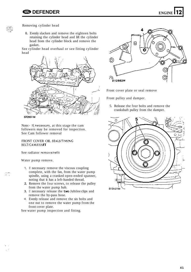
Removing cylinder head
8. Evenly slacken and remove the eighteen bolts retaining the cylinder head and lift the cylinder head from the cylinder block and remove the gasket.
See cylinder head overhaul or s e e fitting cylinder head
ST2951 M
Note:- If..necessary, at this stage the cam followers may b e removed for inspection. See Cam follower removal
FRONT COVER OIL SEALS/TIMINC BE LT/CAM S HA fi
See radiator removehefit
Water pump remove.
1. If necessary remove the viscous coupling complete, with the fan, from the water pump spindle, using a cranked open-ended spanner, noting that it has a left-handed thread.
2. Remove the four screws, t o release the pulley from the water pump hub.
3. I f necessary release the two Jubilee clips and remove the by-pass hose.
4. Evenly release and remove the six bolts and one nut t o remove the water pump from the front cover plate.
See water pump inspection and fitting.
ST2952M
Front cover plate or seal remove
Front pulley and damper.
5. Release the four bolts and remove the crankshaft pulley from the damper.
1 .
41
12
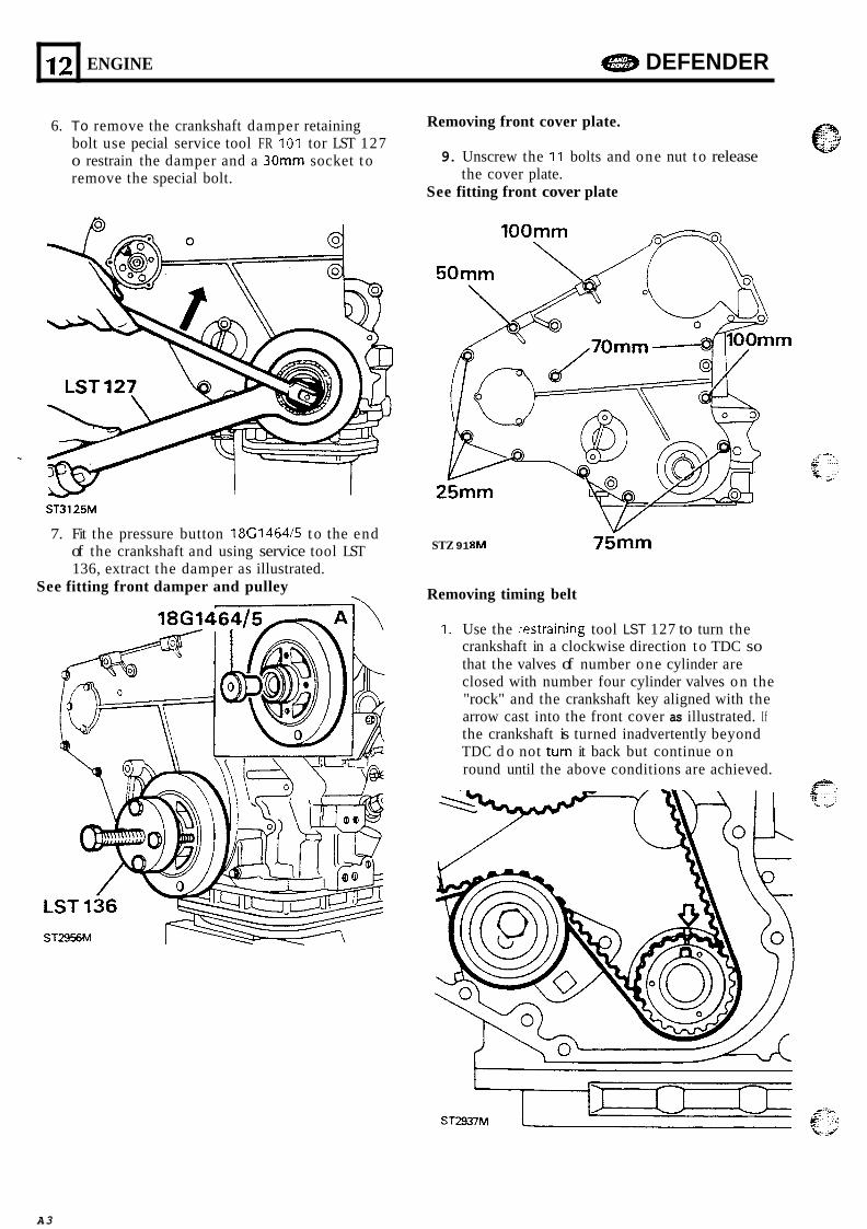
6. To remove the crankshaft damper retaining bolt use pecial service tool FR I01 tor LST 127 o restrain the damper and a 30" socket t o remove the special bolt.
ENGINE a DEFENDER
Removing front cover plate.
9. Unscrew the 11 bolts and one nut t o release the cover plate.
See fitting front cover plate
ST3125M
7. Fit the pressure button 18G1464/5 to the end of the crankshaft and using service tool LST 136, extract the damper as illustrated.
See fitting front damper and pulley
STZ 91 8M 75"
Removing timing belt
1. Use the xstraining tool LST 127 to turn the crankshaft in a clockwise direction to TDC so that the valves of number one cylinder are closed with number four cylinder valves on the "rock" and the crankshaft key aligned with the arrow cast into the front cover as illustrated. If the crankshaft is turned inadvertently beyond TDC d o not turn it back but continue on round until the above conditions are achieved.
e. Q , .. 'J/
A3
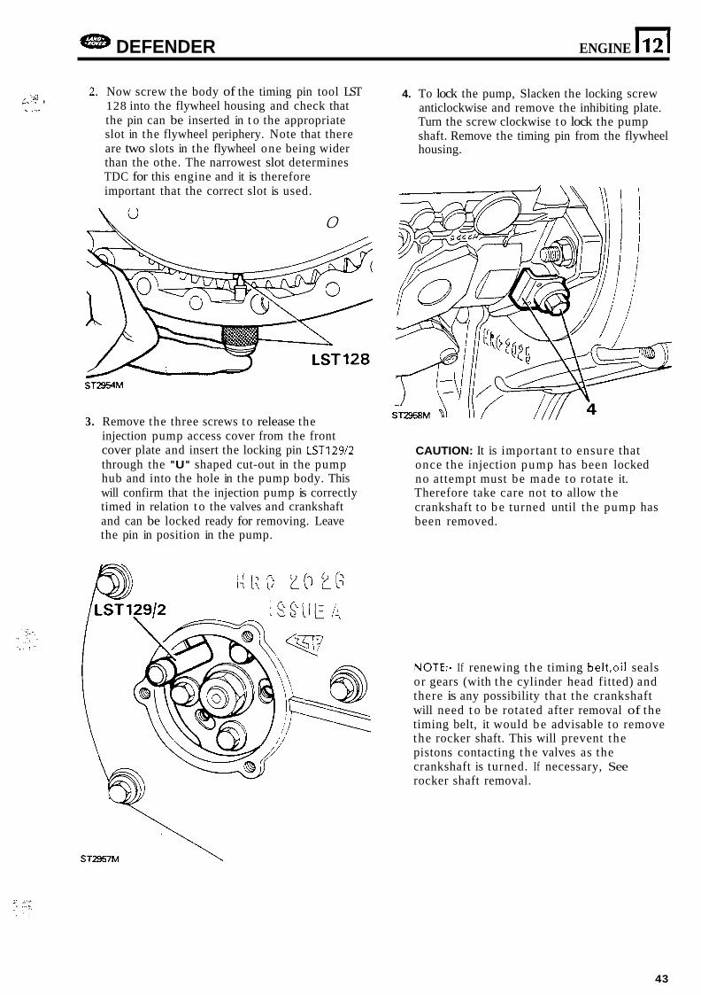
DEFENDER ENGINE 11 2 1 2. Now screw the body of the timing pin tool LST
128 into the flywheel housing and check that the pin can be inserted in t o the appropriate slot in the flywheel periphery. Note that there are two slots in the flywheel one being wider than the othe. The narrowest slot determines TDC for this engine and it is therefore important that the correct slot is used.
4. To lock the pump, Slacken the locking screw anticlockwise and remove the inhibiting plate. Turn the screw clockwise t o lock the pump shaft. Remove the timing pin from the flywheel housing.
I .:!. c. * .
a* 0
ST2954M
3. Remove the three screws to release the injection pump access cover from the front cover plate and insert the locking pin LST129/2 through the "U" shaped cut-out in the pump hub and into the hole in the pump body. This will confirm that the injection pump is correctly timed in relation t o the valves and crankshaft and can be locked ready for removing. Leave the pin in position in the pump.
CAUTION: It is important to ensure that once the injection pump has been locked no attempt must be made to rotate it. Therefore take care not to allow the crankshaft to b e turned until the pump has been removed.
NOTE:- If renewing t h e timing belt,oil seals or gears (with the cylinder head fitted) and there is any possibility that the crankshaft will need t o be rotated after removal of the timing belt, it would b e advisable to remove the rocker shaft. This will prevent the pistons contacting t h e valves as the crankshaft is turned. If necessary, See rocker shaft removal.
.. . . .I .: .. .. - . .,...
43
E[ ENGINE e DEFENDER
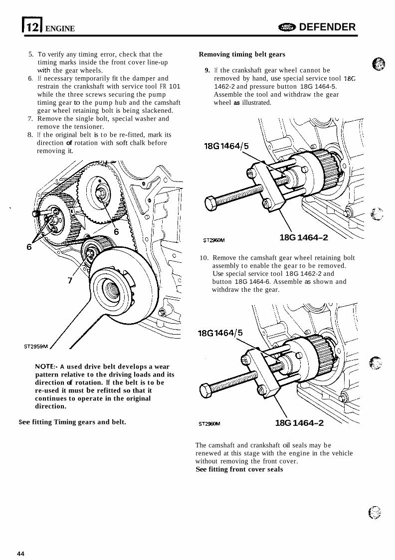
5. To verify any timing error, check that the timing marks inside the front cover line-up with the gear wheels.
6. I f necessary temporarily fit the damper and restrain the crankshaft with service tool FR 101 while the three screws securing the pump timing gear to the pump hub and the camshaft gear wheel retaining bolt is being slackened.
7. Remove the single bolt, special washer and remove the tensioner.
8. I f the original belt is t o be re-fitted, mark its direction of rotation with soft chalk before removing it.
ST2959M/ 1
NOTE:- A used drive belt develops a wear pattern relative to the driving loads and its direction of rotation. If the belt is to be re-used it must be refitted so that it continues to operate in the original direction.
S ee fitting Timing gears and belt.
Removing timing belt gears
9. If the crankshaft gear wheel cannot be removed by hand, use special service tool 18C 1462-2 and pressure button 18G 1464-5. Assemble the tool and withdraw the gear wheel as illustrated.
18G 1464-2 \\\ ST2960M
10. Remove the camshaft gear wheel retaining bolt assembly to enable the gear to be removed. Use special service tool 18G 1462-2 and button 18G 1464-6. Assemble as shown and withdraw the the gear.
ST2960M 18G 1464-2 \\?--.
The camshaft and crankshaft oil seals may be renewed at this stage with the engine in the vehicle without removing the front cover. See fitting front cover seals
44
DEFENDER ENGINE n 12
Removing injection pump Removing front cover I * .I
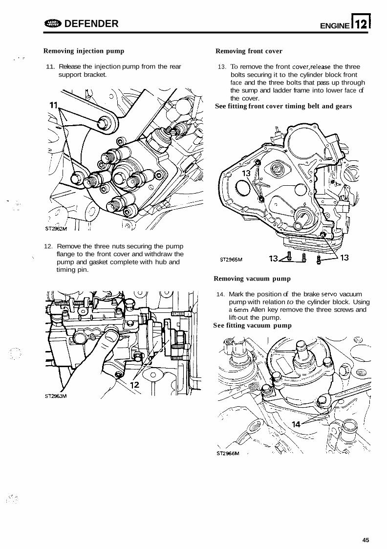
11. Release the injection pump from the rear 13. To remove the front cover,release the three support bracket. bolts securing it to the cylinder block front
face and the three bolts that pass up through the sump and ladder frame into lower face of the cover.
See fitting front cover timing belt and gears
12. Remove the three nuts securing the pump flange to the front cover and withdraw the pump and gasket complete with hub and timing pin.
Removing vacuum pump
14. Mark the position of the brake servo vacuum pump with relation to the cylinder block. Using a 6mm Allen key remove the three screws and lift-out the pump.
See fitting vacuum pump
45
112) ENGINE DEFENDER
Removing skew gear
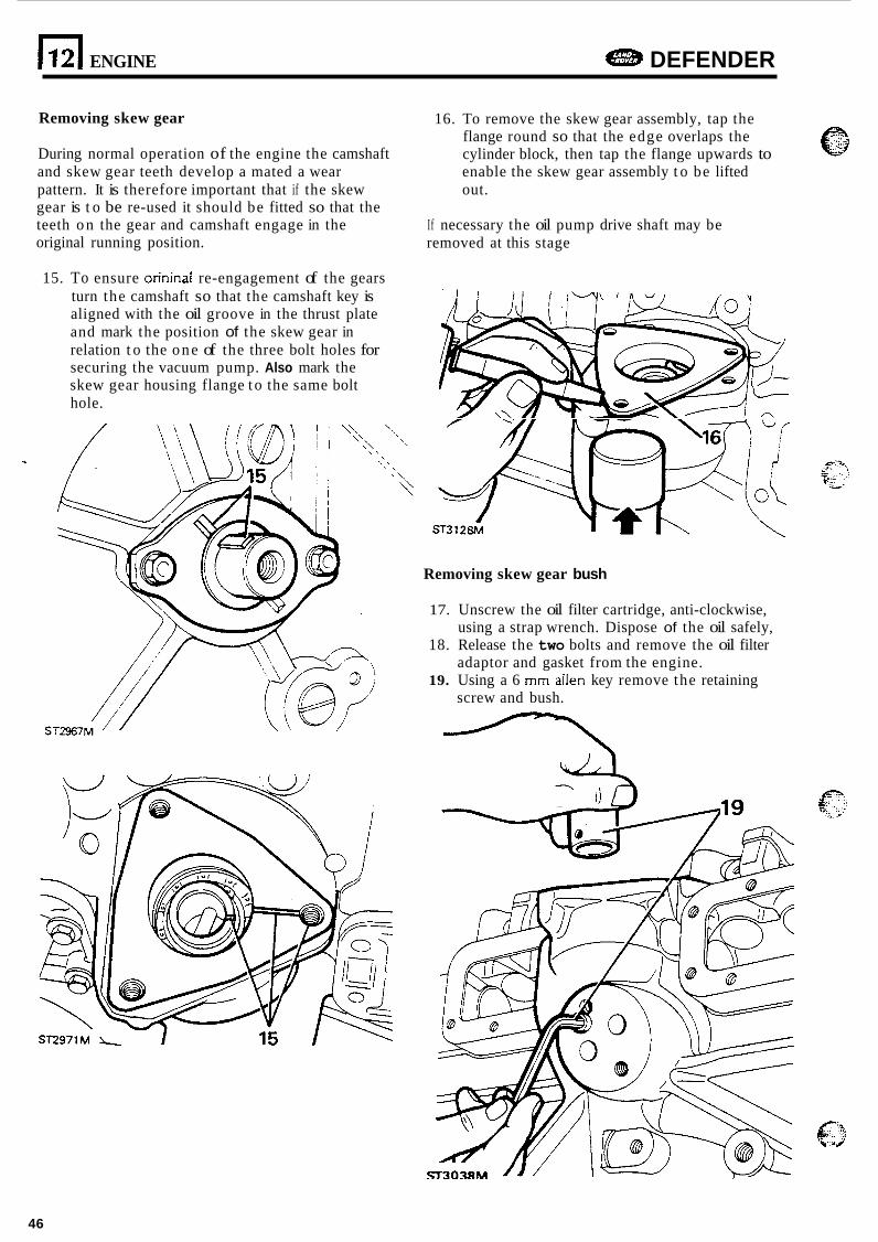
During normal operation of the engine the camshaft and skew gear teeth develop a mated a wear pattern. It is therefore important that if the skew gear is t o be re-used it should be fitted so that the teeth o n the gear and camshaft engage in the original running position.
15. To ensure orininal re-engagement of the gears turn the camshaft so that the camshaft key is aligned with the oil groove in the thrust plate and mark the position of the skew gear in relation t o the o n e of the three bolt holes for securing the vacuum pump. Also mark the skew gear housing flange t o the same bolt hole.
16. To remove the skew gear assembly, tap the flange round so that the edge overlaps the cylinder block, then tap the flange upwards to enable the skew gear assembly t o be lifted out.
If necessary the oil pump drive shaft may be removed at this stage
Removing skew gear bush
17. Unscrew the oil filter cartridge, anti-clockwise, using a strap wrench. Dispose of the oil safely,
18. Release the two bolts and remove the oil filter adaptor and gasket from the engine.
19. Using a 6 mm alien key remove the retaining screw and bush.
46
ENGINE a DEFENDER
Removing fuel p u m p and side cover
12
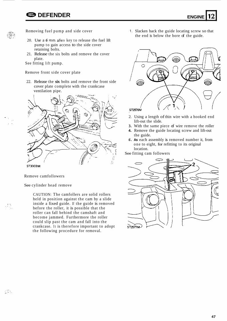
20. Use a 6 mm allen key t o release the fuel lift pump t o gain access to the side cover retaining bolts.
21. Release the six bolts and remove the cover plate.
See fitting l i f t pump.
Remove front s ide cover plate
22. Release the six bolts and remove the front side cover plate complete with the crankcase ventilation pipe.
I 111
ST3003 M
Remove camfollowers
See cylinder head remove
CAUTION: The camfollers a re solid rollers held in position against t h e cam by a slide inside a fixed guide. If t he guide is removed before the roller, it is possible that t h e roller can fall behind the camshaft and become jammed. Furthermore the roller could slip past t he cam and fall into the crankcase. I t is therefore important t o adopt t h e following procedure for removal.
1. Slacken back the guide locating screw so that the end is below the bore of the guide.
x n ' i'
2. Using a length of thin wire with a hooked end
3. With the same piece of wire remove the roller 4. Remove the guide locating screw and lift-out
6 . As each assembly is removed number it, from
lift-out the slide.
the guide.
o n e to eight, for refitting to its original location.
See fitting cam followers
47
12
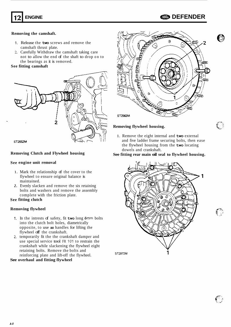
Removing the camshaft.
ENGINE e DEFENDER
1. Release the two screws and remove the camshaft thrust plate.
2. Carefully Withdraw the camshaft taking care not to allow the end of the shaft to drop o n to the bearings as it is removed.
See fitting camshaft
ST2552M
Removing Clutch and Flywheel housing
See
1.
2 .
See
engine unit removal
Mark the relationship of the cover to the flywheel t o ensure original balance is maintained. Evenly slacken and remove the six retaining bolts and washers and remove the assembly complete with the friction plate.
fitting clutch
Removing flywheel
1. In the intrests of safety, fit two long 8mm bolts into the clutch bolt holes, diametrically opposite, t o use as handles for lifting the flywheel off the crankshaft.
2. temporarily fit the the crankshaft damper and use special service tool FR 101 to restrain the crankshaft while slackening the flywheel eight retaining bolts. Remove the bolts and reinforcing plate and lift-off the flywheel.
See overhaul and fitting flywheel
Removing flywheel housing.
1. Remove the eight internal and two external and five ladder frame securing bolts, then ease the flywheel housing from the two locating dowels and crankshaft.
See fitting rear main oil seal to flywheel housing.
ST2972M i
A 8
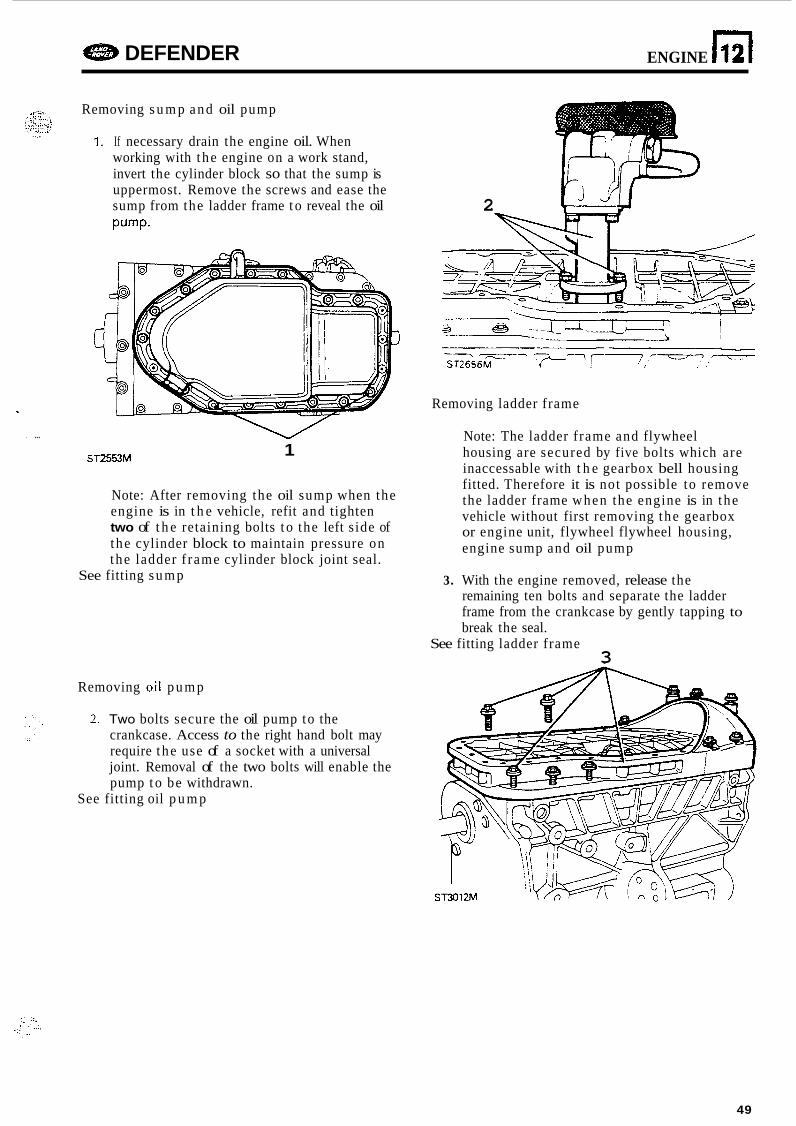
I
I ...
e DEFENDER ENGINE n 12
Removing s u m p and oil pump
1. If necessary drain the engine oil. When working with t he engine on a work stand, invert the cylinder block so that the sump is uppermost. Remove the screws and ease the sump from the ladder frame t o reveal the oil Pump.
1 ST2553M
Note: After removing the oil sump when the engine is in t h e vehicle, refit and tighten two of t h e retaining bolts t o the left s ide of t he cylinder block to maintain pressure on the ladder f rame cylinder block joint seal.
See fitting s u m p
Removing oil p u m p
2. Two bolts secure the oil pump to the crankcase. Access to the right hand bolt may require t he use of a socket with a universal joint. Removal of the two bolts will enable the pump t o be withdrawn.
See fitting oil p u m p
2
Removing ladder frame
Note: The ladder f rame and flywheel housing are secured by five bolts which are inaccessable with t h e gearbox bell housing fitted. Therefore it is not possible to remove the ladder frame when the engine is in the vehicle without first removing the gearbox or engine unit, flywheel flywheel housing, engine sump and oil pump
3. With the engine removed, release the remaining ten bolts and separate the ladder frame from the crankcase by gently tapping to break the seal.
See fitting ladder frame 3
49
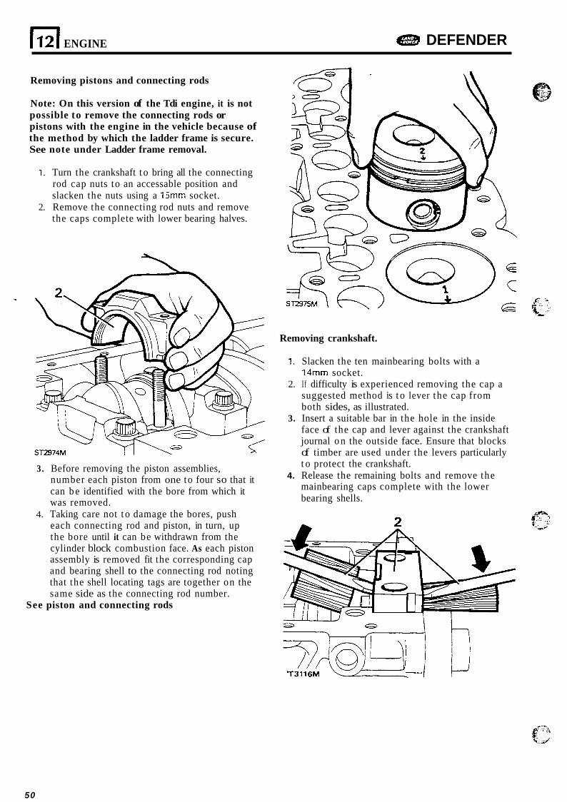
1121 ENGINE DEFENDER
Removing pistons and connecting rods
Note: On this version of the Tdi engine, it is not possible to remove the connecting rods or pistons with the engine in the vehicle because of the method by which the ladder frame is secure. See note under Ladder frame removal.
1. Turn the crankshaft t o bring all the connecting rod cap nuts to an accessable position and slacken the nuts using a 15mm socket.
2. Remove the connecting rod nuts and remove the caps complete with lower bearing halves.
3. Before removing the piston assemblies, number each piston from one to four so that it can b e identified with the bore from which it was removed.
4. Taking care not t o damage the bores, push each connecting rod and piston, in turn, up the bore until it can be withdrawn from the cylinder block combustion face. As each piston assembly is removed fit the corresponding cap and bearing shell to the connecting rod noting that the shell locating tags are together on the same side as the connecting rod number.
See piston and connecting rods
Removing crankshaft.
1. Slacken the ten mainbearing bolts with a 14" socket.
2. If difficulty is experienced removing the cap a suggested method is t o lever the cap from both sides, as illustrated.
3. Insert a suitable bar in the hole in the inside face of the cap and lever against the crankshaft journal o n the outside face. Ensure that blocks of timber are used under the levers particularly t o protect the crankshaft.
mainbearing caps complete with the lower bearing shells.
4. Release the remaining bolts and remove the
50
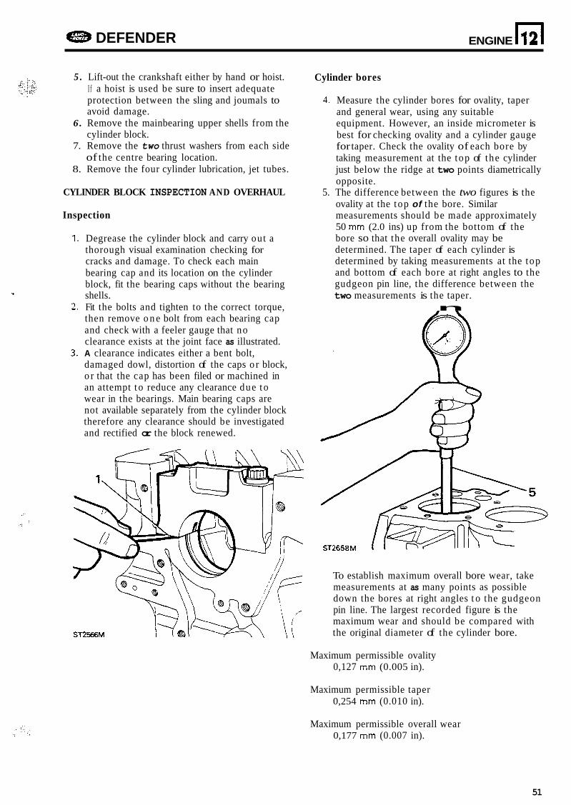
DEFENDER ENGINE n 12
5 . Lift-out the crankshaft either by hand or hoist. I f a hoist is used be sure to insert adequate protection between the sling and joumals to avoid damage.
6. Remove the mainbearing upper shells from the cylinder block.
7. Remove the two thrust washers from each side of the centre bearing location.
8. Remove the four cylinder lubrication, jet tubes.
CYLINDER BLOCK INSPECTION AND OVERHAUL
Inspection
1. Degrease the cylinder block and carry out a thorough visual examination checking for cracks and damage. To check each main bearing cap and its location on the cylinder block, fit the bearing caps without the bearing shells.
2. Fit the bolts and tighten to the correct torque, then remove o n e bolt from each bearing cap and check with a feeler gauge that no clearance exists at the joint face as illustrated.
3. A clearance indicates either a bent bolt, damaged dowl, distortion of the caps o r block, o r that the cap has been filed or machined in an attempt t o reduce any clearance due t o wear in the bearings. Main bearing caps are not available separately from the cylinder block therefore any clearance should be investigated and rectified or the block renewed.
?.
ST2566M
Cylinder bores
4. Measure the cylinder bores for ovality, taper and general wear, using any suitable equipment. However, an inside micrometer is best for checking ovality and a cylinder gauge for taper. Check the ovality of each bore by taking measurement at the top of the cylinder just below the ridge at two points diametrically opposite.
5. The difference between the two figures is the ovality at the top of the bore. Similar measurements should be made approximately 50 mm (2.0 ins) up from the bottom of the bore so that the overall ovality may be determined. The taper of each cylinder is determined by taking measurements at the top and bottom of each bore at right angles to the gudgeon pin line, the difference between the two measurements is the taper.
n
To establish maximum overall bore wear, take measurements at as many points as possible down the bores at right angles t o the gudgeon pin line. The largest recorded figure is the maximum wear and should be compared with the original diameter of the cylinder bore.
Maximum permissible ovality 0,127 mm (0.005 in).
Maximum permissible taper 0,254 mm (0.010 in).
Maximum permissible overall wear 0,177 mm (0.007 in).
51

12
I f the above figures are exceeded the cylinders must
condition of the bores and the amount of wear. Altematively, if the overall wear, taper and ovality are well within the acceptable limits and the original pistons are serviceable new piston rings may be fitted. It is important however, that , the bores are deglazed, with a hone, t o give a cross-hatched finish to provide a seating for the new ring.
' be rebored or sleeved depending upon the
ENGINE DEFENDER
Fitting cylinder sleeves
Cylinder bores that cannot b e rebored can be restored by fitting sleeves t o enable standard size pistons t o be fitted. Sleeving one cylinder only will distort the adjacent bore so sleeving must be carried out in pairs, i.e. cylinders 1 and 2 or 3 and 4.
6. Machine the cylinder bores t o accept the sleeves to 94,425 + 0,012 mm (3.7175 + 0.0005 in). This will give the sleeve a 0,076 t o 0,114 mm (0.003 t o 0.0045 in) interference fit. Press the sleeves squarely into the bore using a pressure of two or three tons. Excessive pressure could damage the sleeve and cylinder block.
The sleeves must not be proud of the cylinder block top face or more than 2,54 mm (0.10 in) below the surface.
7, Bore and hone the sleeves to accomodate the pistons with the required clearances, see piston and connecting rod examination.
Camshaft bearings
8. Measure the intemal diameter of each camshaft bearing at several points using an internal micrometer.
A comparison of the bearing diameters with those of the respective camshaft joumals will give the amount of clearance. The bearings should be renewed if the clearance exceeds 0,0508 mm (0.002 in). Or, in any event, if they are scored or pitted. This work should only be entrusted to line boring specialists.
It is vital t o thoroughly wash the cylinder block after machining t o remove all traces of abrasive material, ensuring that all oil galleries are clean.
Check crankcase main bearings
Discard scored, pitted, cracked and wom bearing shells. To determine the maximum wear, assemble the main bearing shells and caps t o the crankcase and tighten the bolts t o the correct torque figure.
Using an inside micrometer, measure each bearing at several points and note the greatest figure. The maximum wear is the difference between this figure and the smallest diameter of the corresponding crankshaft journal.
The main bearing running clearance is given in the data section.
CRANKSHAm
1. Degrease the crankshaft and clear out the oil ways which can become clogged after long service.
bearing joumals for obvious wear, scores, grooves and overheating. A decision at this stage should be made as t o whether the condition of the shaft is worth continuing with a more detailed examination.
ovality and taper of each main bearing journal and crankpin as follows.
2. Examine visually, the crankpins and main
3. With a micrometer, measure and note the
4. Ovality - Take two readings at right angles t o each other at various intervals. The maximum ovality must not exceed 0,040 mm (0.0015 in).
other at both ends of the main bearing journal and crankpin. The maximum permissible taper must not exceed 0,025 mm (0.001 in).
6. To check for straightness, support the front and rear main bearing joumals in 'V' blocks and postion a dial indicator to check the run-out at the centre main bearing journal. Run-out must not exceed 0,076 mm (0.003 in) taking into account any ovality ir. the centre journal. The overall wear limit should not exceed 0,114 mm (0.0045 in) for main bearing joumals and 0,088 mm (0.0035 in) for crankpins.
7. A crankshaft w o m beyond the limints of maximum taper, ovality and overall wear, can be ground to0,25 mm (0.010 in).
5. Taper - Take two readings parallel t o each
When grinding the crankshaft main bearing and crankpin joumals, rotation of the grinding wheel and crankshaft must b e in the same direction, anti-clockwise, viewed from the flywheel end of the crankshaft.
52
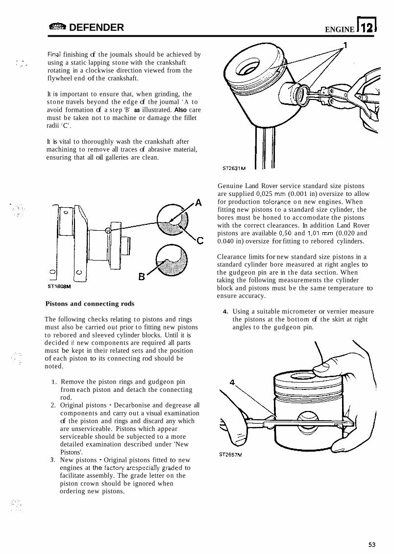
DEFENDER ENGINE n 12
Finai finishing of the joumals should be achieved by using a static lapping stone with the crankshaft rotating in a clockwise direction viewed from the flywheel end of the crankshaft.
. * ' .. 11
It is important to ensure that, when grinding, the s tone travels beyond the edge of the joumal ' A to avoid formation of a step 'B' as illustrated. Also care must be taken not t o machine or damage the fillet radii 'C.
It is vital to thoroughly wash the crankshaft after machining to remove all traces of abrasive material, ensuring that all oil galleries are clean.
ST1808M
Pistons and connecting rods
The following checks relating t o pistons and rings must also be carried out prior t o fitting new pistons to rebored and sleeved cylinder blocks. Until it is decided if new components are required all parts must be kept in their related sets and the position of each piston to its connecting rod should be noted.
1. Remove the piston rings and gudgeon pin from each piston and detach the connecting rod.
2. Original pistons - Decarbonise and degrease all components and carry out a visual examination of the piston and rings and discard any which are unserviceable. Pistons which appear serviceable should be subjected to a more detailed examination described under 'New Pistons'.
3. New pistons - Original pistons fitted to new engines at the factor? arespecially graded to facilitate assembly. The grade letter on the piston crown should be ignored when ordering new pistons.
Genuine Land Rover service standard size pistons are supplied 0,025 mm (0.001 in) oversize to allow for production tolorance o n new engines. When fitting new pistons t o a standard size cylinder, the bores must be honed t o accomodate the pistons with the correct clearances. In addition Land Rover pistons are available 0,50 and 1 , O l mm (0.020 and 0.040 in) oversize for fitting to rebored cylinders.
Clearance limits for new standard size pistons in a standard cylinder bore measured at right angles to the gudgeon pin are in the data section. When taking the following measurements the cylinder block and pistons must b e the same temperature to ensure accuracy.
4. Using a suitable micrometer or vernier measure the pistons at the bottom of the skirt at right angles t o the gudgeon pin.
ST2657M
53
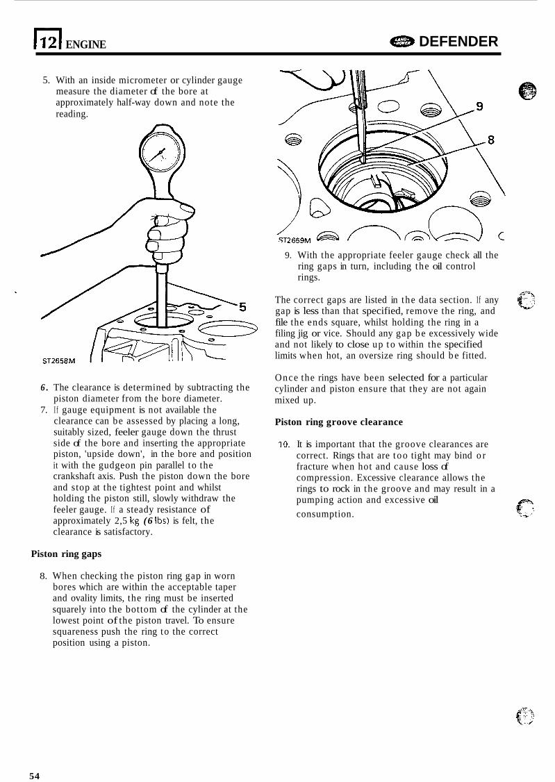
1121 ENGINE e DEFENDER
5. With an inside micrometer or cylinder gauge measure the diameter of the bore at approximately half-way down and note the reading.
6 . The clearance is determined by subtracting the
7. I f gauge equipment is not available the piston diameter from the bore diameter.
clearance can be assessed by placing a long, suitably sized, feeler gauge down the thrust side of the bore and inserting the appropriate piston, 'upside down', in the bore and position it with the gudgeon pin parallel to the crankshaft axis. Push the piston down the bore and stop at the tightest point and whilst holding the piston still, slowly withdraw the feeler gauge. I f a steady resistance of approximately 2,5 kg (6 Ibs) is felt, the clearance is satisfactory.
Piston ring gaps
9. With the appropriate feeler gauge check all the ring gaps in turn, including the oil control rings.
The correct gaps are listed in the data section. If any gap is less than that specified, remove the ring, and file the ends square, whilst holding the ring in a filing jig or vice. Should any gap b e excessively wide and not likely to close up t o within the specified limits when hot, an oversize ring should b e fitted.
Once the rings have been selected for a particular cylinder and piston ensure that they are not again mixed up.
Piston ring groove clearance
10. It is important that the groove clearances are correct. Rings that are t oo tight may bind o r fracture when hot and cause loss of compression. Excessive clearance allows the rings to rock in the groove and may result in a pumping action and excessive oil
p ': consumption. z 4 6 9 4
8. When checking the piston ring gap in worn bores which are within the acceptable taper and ovality limits, the ring must be inserted squarely into the bottom of the cylinder at the lowest point of the piston travel. To ensure squareness push the ring to the correct position using a piston.
54
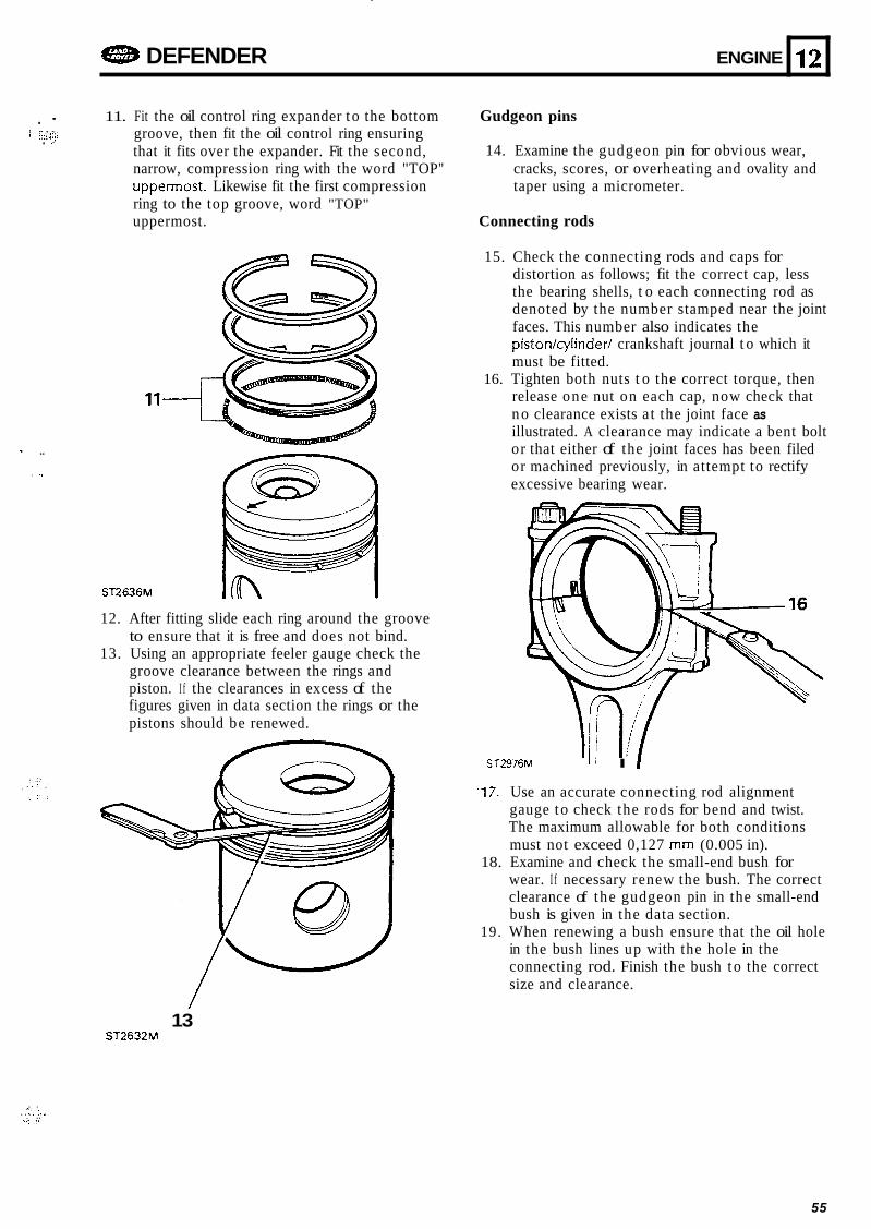
DEFENDER ENGINE
. - 1 -,.":.<.
11. Fit the oil control ring expander t o the bottom groove, then fit the oil control ring ensuring that it fits over the expander. Fit the second, narrow, compression ring with the word "TOP" uppermost. Likewise fit the first compression ring to the top groove, word "TOP" uppermost.
. :
12
11-
- .. . ..
ST2636M
c
12. After fitting slide each ring around the groove to ensure that it is free and does not bind.
13. Using an appropriate feeler gauge check the groove clearance between the rings and piston. I f the clearances in excess of the figures given in data section the rings or the pistons should be renewed.
Gudgeon pins
14. Examine the gudgeon pin for obvious wear, cracks, scores, or overheating and ovality and taper using a micrometer.
Connecting rods
15. Check the connecting rods and caps for distortion as follows; fit the correct cap, less the bearing shells, t o each connecting rod as denoted by the number stamped near the joint faces. This number also indicates the piston/cylinder/ crankshaft journal t o which it must be fitted.
16. Tighten both nuts t o the correct torque, then release one nut on each cap, now check that n o clearance exists a t the joint face as illustrated. A clearance may indicate a bent bolt or that either of the joint faces has been filed or machined previously, in attempt to rectify excessive bearing wear.
ST2976M " I I
-17. Use an accurate connecting rod alignment gauge t o check the rods for bend and twist. The maximum allowable for both conditions must not exceed 0,127 mm (0.005 in).
18. Examine and check the small-end bush for wear. I f necessary renew the bush. The correct clearance of the gudgeon pin in the small-end bush is given in the data section.
in the bush lines up with the hole in the connecting rod. Finish the bush t o the correct size and clearance.
19. When renewing a bush ensure that the oil hole
13 ST2632M
. . - . '_. :, 1 . . . . . _.. . .. . .
55
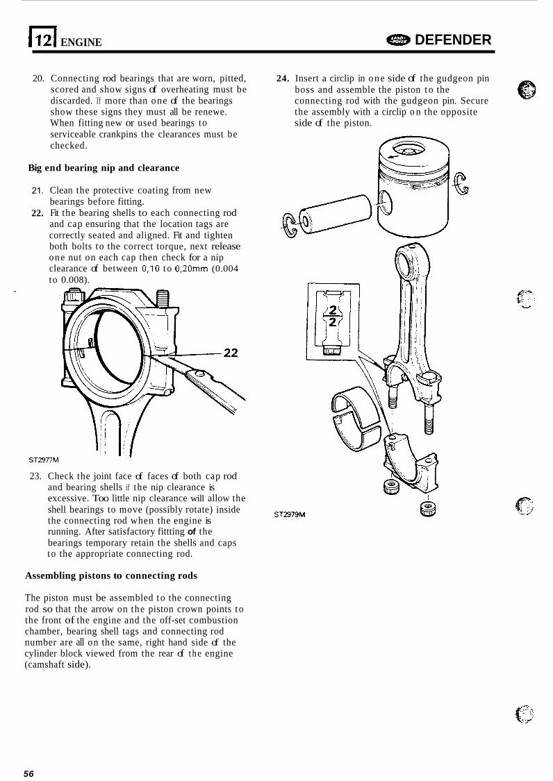
(121 ENGINE DEFENDER
20. Connecting rod bearings that are worn, pitted, scored and show signs of overheating must be discarded. If more than one of the bearings show these signs they must all be renewe. When fitting new or used bearings to serviceable crankpins the clearances must be checked.
Big end bearing nip and clearance
21.
22.
Clean the protective coating from new bearings before fitting. Fit the bearing shells to each connecting rod and cap ensuring that the location tags are correctly seated and aligned. Fit and tighten both bolts to the correct torque, next release one nut on each cap then check for a nip clearance of between 0,lO t o 0,20mm (0.004 to 0.008).
- . ST2977M
23. Check the joint face of faces of both cap rod and bearing shells if the nip clearance is excessive. Too little nip clearance will allow the shell bearings to move (possibly rotate) inside the connecting rod when the engine is running. After satisfactory fittting of the bearings temporary retain the shells and caps to the appropriate connecting rod.
Assembling pistons to connecting rods
24. Insert a circlip in o n e side of the gudgeon pin boss and assemble the piston t o the connecting rod with the gudgeon pin. Secure the assembly with a circlip o n the opposite side of the piston.
W
ST2979M
The piston must be assembled t o the connecting rod so that the arrow on the piston crown points t o the front of the engine and the off-set combustion chamber, bearing shell tags and connecting rod number are all on the same, right hand side of the cylinder block viewed from the rear of the engine (camshaft side).
56
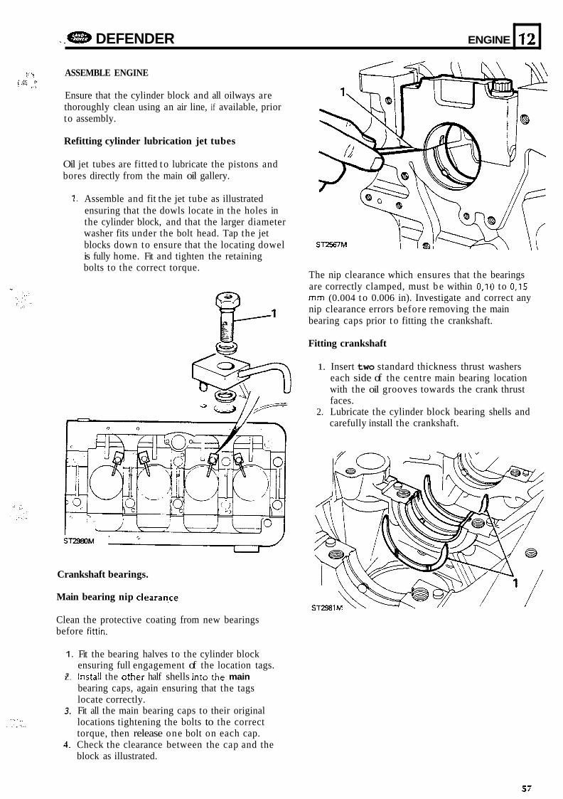
.. e DEFENDER ENGINE
'-? ASSEMBLE ENGINE 2, 9
. I
Ensure that the cylinder block and all oilways are thoroughly clean using an air line, if available, prior to assembly.
12
Refitting cylinder lubrication jet tubes
Oil jet tubes are fitted t o lubricate the pistons and bores directly from the main oil gallery.
,.,-. ~
. I . ., . . , ...
1. Assemble and fit the jet tube as illustrated ensuring that the dowls locate in the holes in the cylinder block, and that the larger diameter washer fits under the bolt head. Tap the jet blocks down to ensure that the locating dowel is fully home. Fit and tighten the retaining bolts to the correct torque.
ST2980M
Crankshaft bearings.
Main bearing nip clearaqce
Clean the protective coating from new bearings before fittin.
1.
3 L.
3.
4.
Fit the bearing halves to the cylinder block ensuring full engagement of the location tags. Instal! the othei half shells into the main bearing caps, again ensuring that the tags locate correctly. Fit all the main bearing caps to their original locations tightening the bolts to the correct torque, then release one bolt on each cap. Check the clearance between the cap and the block as illustrated.
The nip clearance which ensures that the bearings are correctly clamped, must b e within 0,IO to 0,15 mm (0.004 t o 0.006 in). Investigate and correct any nip clearance errors before removing the main bearing caps prior t o fitting the crankshaft.
Fitting crankshaft
1. Insert two standard thickness thrust washers each side of the centre main bearing location with the oil grooves towards the crank thrust faces.
carefully install the crankshaft. 2. Lubricate the cylinder block bearing shells and
57
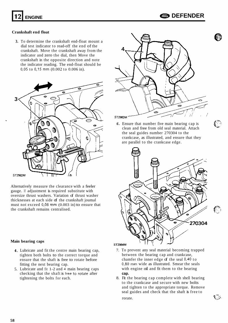
12
Crankshaft end float
e DEFENDER ENGINE
3. To determine the crankshaft end-float mount a dial test indicator t o read-off the end of the crankshaft. Move the crankshaft away from the indicator and zero the dial, then Move the crankshaft in the opposite direction and note the indicator reading. The end-float should be 0,05 t o 0,15 mm (0.002 t o 0.006 in).
Alternatively measure the clearance with a feeler gauge. I f adjustment is required substitute with oversize thrust washers. Variation of thrust washer thicknesses at each side of the crankshaft joumal must not exceed 0,08 mm (0.003 in) to ensure that the crankshaft remains centralised.
Main bearing caps
4.
5.
6 . Ensure that number five main bearing cap is clean and free from old seal material. Attach the seal guides number 270304 to the crankcase, as illustrated, and ensure that they are parallel t o the crankcase edge.
Sl
Lubricate and fit the centre main bearing cap, tighten both bolts to the correct torque and ensure that the shaft is free to rotate before fitting the next bearing cap. Lubricate and fit 1-2 and 4 main bearing caps
tightening the bolts for each.
7. To prevent any seal material becoming trapped between the bearing cap and crankcase, chamfer the inner edge of the seal 0,40 t o 0,80 mm wide as illustrated. Smear the seals with engine oil and fit them to the bearing cap.
8. Fit the bearing cap complete with shell bearing t o the crankcase and secure with new bolts and tighten t o the appropriate torque. Remove seal guides and check that the shaft is f ree t o
checking that the shaft is free t e rdate after
c-?: rorate. e 2
58
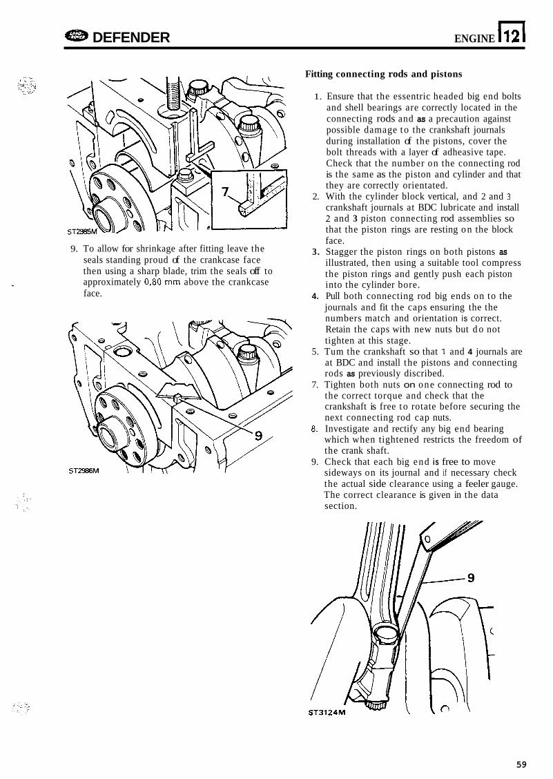
DEFENDER ENGINE n 12
Fitting connecting rods and pistons
1. Ensure that the essentric headed big end bolts and shell bearings are correctly located in the connecting rods and as a precaution against possible damage t o the crankshaft journals during installation of the pistons, cover the bolt threads with a layer of adheasive tape. Check that the number on the connecting rod is the same as the piston and cylinder and that they are correctly orientated.
2. With the cylinder block vertical, and 2 and 3 crankshaft journals at BDC lubricate and install 2 and 3 piston connecting rod assemblies so that the piston rings are resting o n the block face.
illustrated, then using a suitable tool compress the piston rings and gently push each piston
4. Pull both connecting rod big ends on to the journals and fit the caps ensuring the the numbers match and orientation is correct. Retain the caps with new nuts but d o not tighten at this stage.
at BDC and install the pistons and connecting rods as previously discribed.
the correct torque and check that the crankshaft is free t o rotate before securing the next connecting rod cap nuts.
which when tightened restricts the freedom of the crank shaft.
sideways on its journal and if necessary check the actual side clearance using a feeler gauge. The correct clearance is given in the data section.
9. To allow for shrinkage after fitting leave the 3. Stagger the piston rings on both pistons as seals standing proud of the crankcase face then using a sharp blade, trim the seals off to
face. .. approximately 0,80 mm above the crankcase into the cylinder bore.
5. Tum the crankshaft so that I and 4 journals are
7. Tighten both nuts on one connecting rod to
8. Investigate and rectify any big end bearing
9. Check that each big end is free to move
59
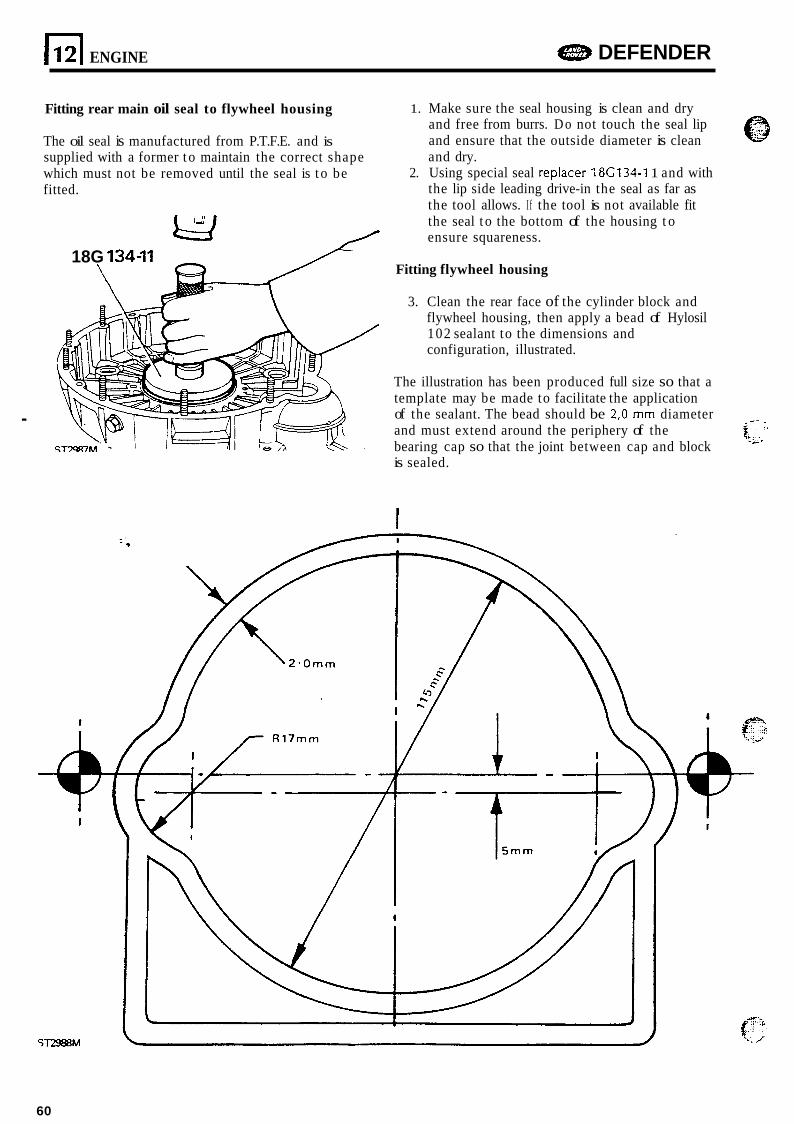
.
ENGINE DEFENDER
Fitting rear main oil seal to flywheel housing
The oil seal is manufactured from P.T.F.E. and is supplied with a former t o maintain the correct shape which must not be removed until the seal is t o be fitted.
18G 134-11
\
1. Make sure the seal housing is clean and dry and free from burrs. D o not touch the seal lip and ensure that the outside diameter is clean and dry.
2. Using special seal replacer 18C134-I 1 and with the lip side leading drive-in the seal as far as the tool allows. I f the tool is not available fit the seal t o the bottom of the housing t o ensure squareness.
Fitting flywheel housing
3. Clean the rear face of the cylinder block and flywheel housing, then apply a bead of Hylosil 102 sealant to the dimensions and configuration, illustrated.
The illustration has been produced full size so that a template may be made to facilitate the application of the sealant. The bead should be 2,O mm diameter and must extend around the periphery of the bearing cap so that the joint between cap and block is sealed.
~ - _ _ L,**
I
ST2988M
60
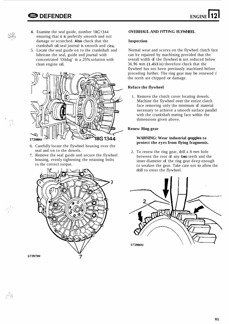
a DEFENDER ENGINE n 12
4. Examine the seal guide, number 18G1344 ensuring that it is perfectly smooth and not damage o r scratched. Also check that the crankshaft oil seal journal is smooth and clea.
5. Locate the seal guide on t o the crankshaft and lubricate the seal, guide and journal with concentrated 'Oildag' in a 25% solution with clean engine oil.
6. Carefully locate the flywheel housing over the seal and o n t o the dowels.
7. Remove the seal guide and secure the flywheel housing, evenly tightening the retaining bolts t o the correct torque.
OVERHAUL AND FITJING FLYWHEEL
Inspection
Normal wear and scores on the flywheel clutch face can b e repaired by machining provided that the overall width of the flywheel is not reduced below 36,96 mm (1.453 in) therefore check that the flywheel has not been previously machined before proceding further. The ring gear may be renewed if the teeth are chipped or damage.
Reface the flywheel
1. Remove the clutch cover locating dowels. Machine the flywheel over the entire clutch face removing only the minimum of material necessary to achieve a smooth surface parallel with the crankshaft mating face within the dimensions given above.
Renew Ring gear
WARNING: Wear industrial goggles to protect the eyes from flying fragments.
2. To renew the ring gear, drill a 8 mm hole between the root of any two teeth and the inner diameter of the ring gear deep enough t o weaken the gear. Take care not to allow the drill to enter the flywheel.
ST2973M 7
61
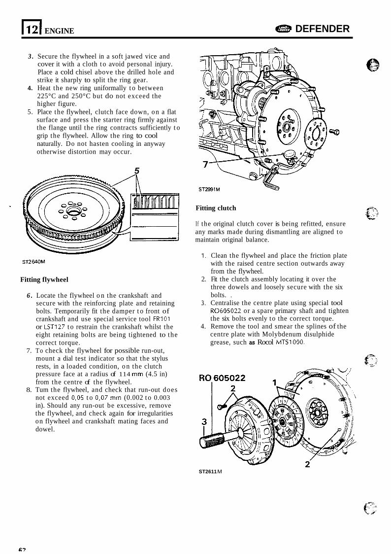
El ENGINE DEFENDER
3 . Secure the flywheel in a soft jawed vice and cover it with a cloth t o avoid personal injury. Place a cold chisel above the drilled hole and strike it sharply to split the ring gear.
4. Heat the new ring uniformally t o between 225°C and 250°C but do not exceed the higher figure.
5. Place the flywheel, clutch face down, on a flat surface and press the starter ring firmly against the flange until the ring contracts sufficiently t o grip the flywheel. Allow the ring to cool naturally. Do not hasten cooling in anyway otherwise distortion may occur.
5
ST2640M
Fitting flywheel
6 . Locate the flywheel o n the crankshaft and secure with the reinforcing plate and retaining bolts. Temporarily fit the damper t o front of crankshaft and use special service tool F R I O I or LST127 t o restrain the crankshaft whilst the eight retaining bolts are being tightened to the correct torque.
mount a dial test indicator so that the stylus rests, in a loaded condition, o n the clutch pressure face at a radius of 114 mm (4.5 in) from the centre of the flywheel.
8. Tum the flywheel, and check that run-out does not exceed 0,05 t o 0,07 mm (0.002 t o 0.003 in). Should any run-out be excessive, remove the flywheel, and check again for irregularities on flywheel and crankshaft mating faces and dowel.
7. To check the flywheel for possible run-out,
ST2991M
Fitting clutch
I f the original clutch cover is being refitted, ensure any marks made during dismantling are aligned to maintain original balance.
1. Clean the flywheel and place the friction plate with the raised centre section outwards away from the flywheel.
three dowels and loosely secure with the six bolts. .
3. Centralise the centre plate using special tool R0605022 or a spare primary shaft and tighten the six bolts evenly to the correct torque.
4. Remove the tool and smear the splines of the centre plate with Molybdenum disulphide grease, such as Rocol MTS1000.
2. Fit the clutch assembly locating it over the
ST2611 M
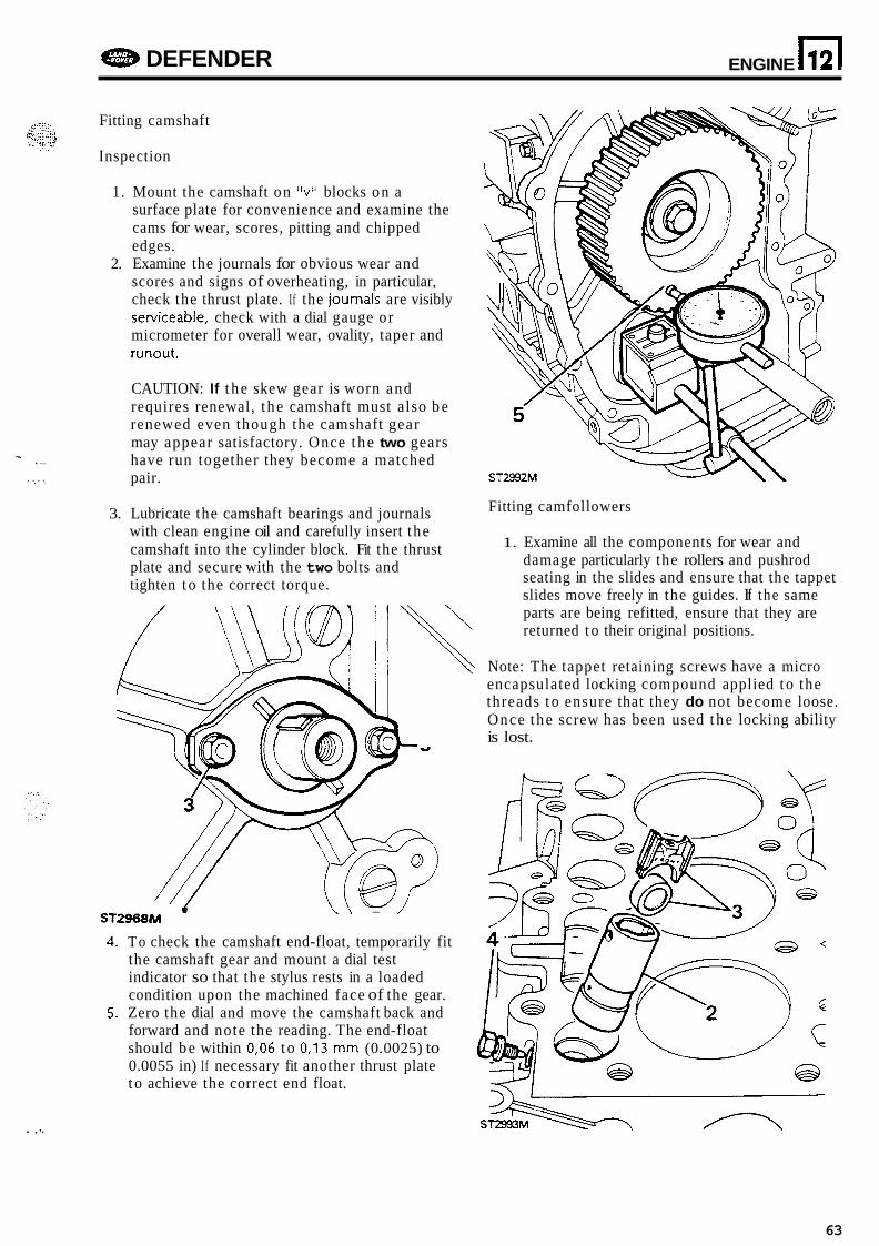
e DEFENDER ENGINE n 12
T . .. . . . . . .
Fitting camshaft
Inspection
1. Mount the camshaft on "v" blocks on a surface plate for convenience and examine the cams for wear, scores, pitting and chipped edges.
2. Examine the journals for obvious wear and scores and signs of overheating, in particular, check the thrust plate. If the journals are visibly sewiceable, check with a dial gauge or micrometer for overall wear, ovality, taper and runout.
CAUTION: If t h e skew gear is worn and requires renewal, t he camshaft must also b e renewed even though the camshaft gear may appear satisfactory. Once t h e two gears have run together they become a matched pair.
3. Lubricate the camshaft bearings and journals with clean engine oil and carefully insert the camshaft into the cylinder block. Fit the thrust plate and secure with the two bolts and tighten t o the correct torque.
Fitting camfollowers
1. Examine all the components for wear and damage particularly the rollers and pushrod seating in the slides and ensure that the tappet slides move freely in the guides. If t he same parts are being refitted, ensure that they are returned t o their original positions.
Note: The tappet retaining screws have a micro encapsulated locking compound applied t o the threads t o ensure that they do not become loose. Once the screw has been used t h e locking ability is lost.
\ \ - / ST2968M ' 4. T o check the camshaft end-float, temporarily fit
the camshaft gear and mount a dial test indicator so that the stylus rests in a loaded condition upon the machined face of the gear.
5. Zero the dial and move the camshaft back and forward and note the reading. The end-float should b e within 0,06 t o 0,13 mm (0.0025) to 0.0055 in) I f necessary fit another thrust plate t o achieve the correct end float.
. , 1.
63
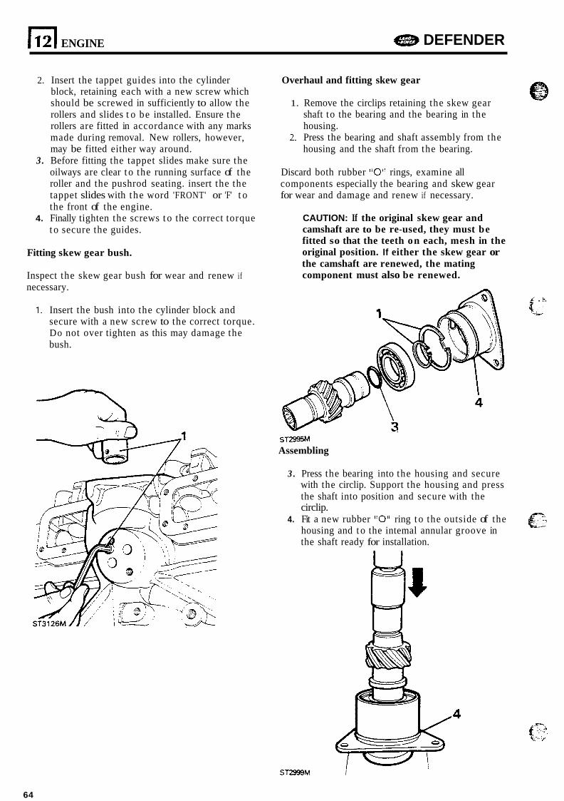
112) ENGINE e DEFENDER
2. Insert the tappet guides into the cylinder block, retaining each with a new screw which should be screwed in sufficiently to allow the rollers and slides t o be installed. Ensure the rollers are fitted in accordance with any marks made during removal. New rollers, however, may be fitted either way around.
3. Before fitting the tappet slides make sure the oilways are clear t o the running surface of the roller and the pushrod seating. insert the the tappet slides with t he word 'FRONT' or 'F' t o the front of the engine.
4. Finally tighten the screws t o the correct torque t o secure the guides.
Fitting skew gear bush.
Inspect the skew gear bush for wear and renew if necessary.
1. Insert the bush into the cylinder block and secure with a new screw to the correct torque. Do not over tighten as this may damage the bush.
Overhaul and fitting skew gear
1. Remove the circlips retaining the skew gear shaft to the bearing and the bearing in the housing.
2. Press the bearing and shaft assembly from the housing and the shaft from the bearing.
Discard both rubber "0" rings, examine all components especially the bearing and skew gear for wear and damage and renew if necessary.
CAUTION: If the original skew gear and camshaft are to be re-used, they must be fitted so that the teeth on each, mesh in the original position. If either the skew gear or the camshaft are renewed, the mating component must also be renewed.
1' . h\ 4,
ST2995M Assembling
3 . Press the bearing into the housing and secure with the circlip. Support the housing and press the shaft into position and secure with the circlip.
4. Fit a new rubber "0" ring t o the outside of the housing and t o the intemal annular groove in the shaft ready for installation.
r- <L-
ST2999M I
64
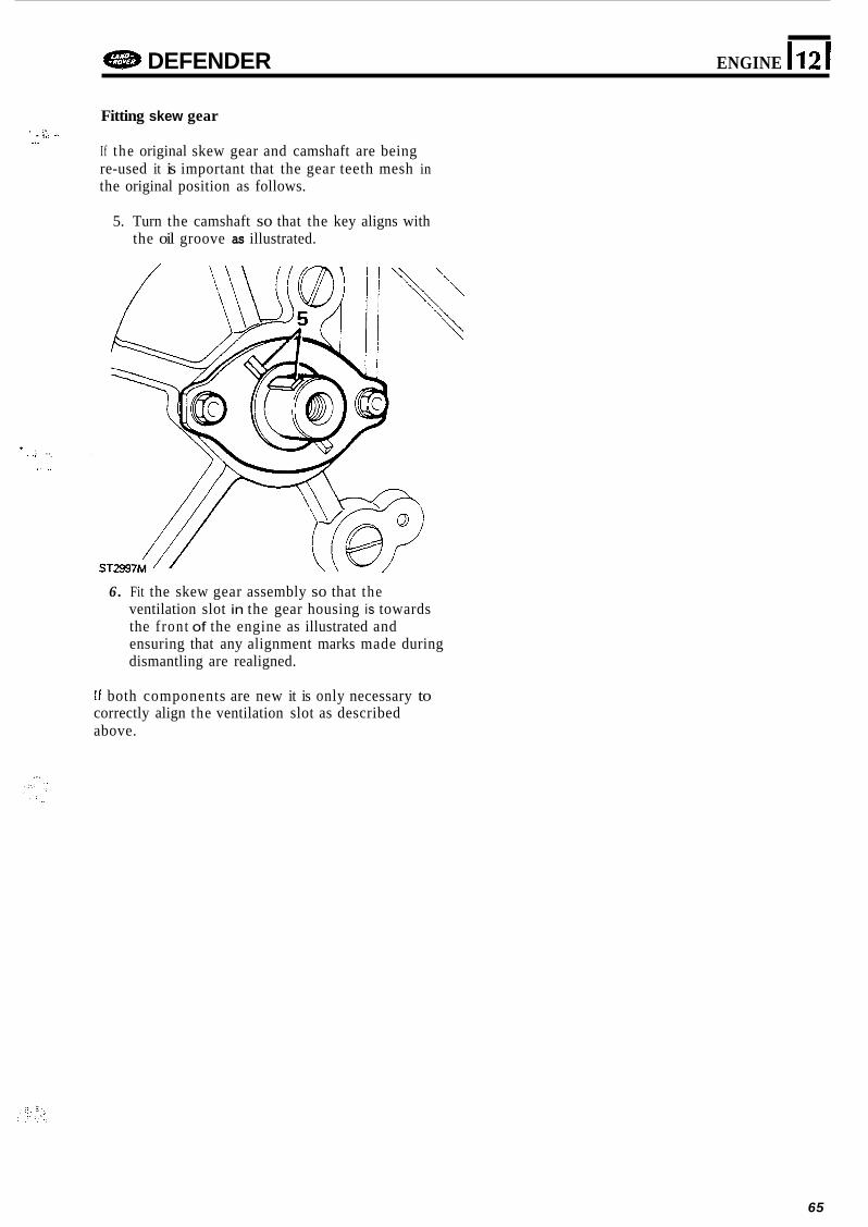
e DEFENDER ENGINE 1121
Fitting skew gear
If t he original skew gear and camshaft are being re-used it is important that the gear teeth mesh in the original position as follows.
1 . $:. d _.
5. Turn the camshaft so that the key aligns with the oil groove as illustrated.
* I . . .. . . .
,! ..
6. Fit the skew gear assembly so that the ventilation slot in the gear housing is towards the f ront of the engine as illustrated and ensuring that any alignment marks made during dismantling are realigned.
I f both components are new it is only necessary to correctly align the ventilation slot as described above.
65
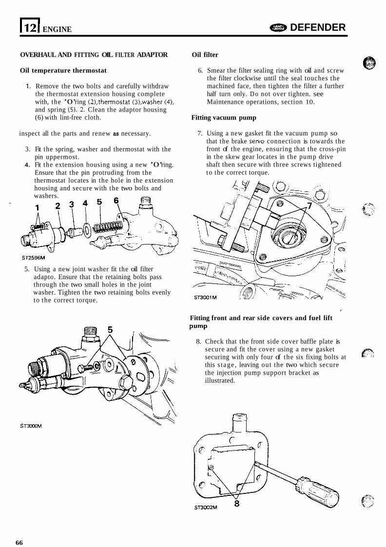
1121 ENGINE DEFENDER
OVERHAUL AND FITTING OIL FILTER ADAPTOR
Oil temperature thermostat
1. Remove the two bolts and carefully withdraw the thermostat extension housing complete with, the ’0’ ring (21,thermostat (3),washer (41, and spring (5). 2. Clean the adaptor housing (6) with lint-free cloth.
inspect all the parts and renew as necessary.
3. Fit the spring, washer and thermostat with the pin uppermost.
4. Fit the extension housing using a new ’0’ ring. Ensure that the pin protruding from the thermostat locates in the hole in the extension housing and secure with the two bolts and
.+
washers.
1- ? ? ? ? \
- ST2596M
5. Using a new joint washer fit the oil filter adapto. Ensure that t he retaining bolts pass through the two small holes in the joint washer. Tighten the two retaining bolts evenly to the correct torque.
Oil filter
6. Smear the filter sealing ring with oil and screw the filter clockwise until the seal touches the machined face, then tighten the filter a further half turn only. D o not over tighten. see Maintenance operations, section 10.
Fitting vacuum pump
7. Using a new gasket fit the vacuum pump so that the brake servo connection is towards the front of the engine, ensuring that the cross-pin in the skew gear locates in the pump drive shaft then secure with three screws tightened to the correct torque.
I
Fitting front and rear side covers and fuel lift Pump
8. Check that the front side cover baffle plate is secure and fit the cover using a new gasket securing with only four of the six fixing bolts at this s tage , leaving out the two which secure the injection pump support bracket as illustrated.
P
ST3000M
66
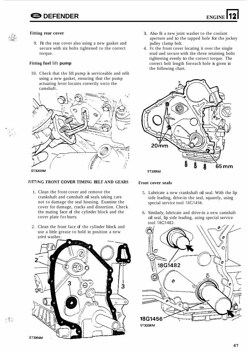
e DEFENDER ENGINE n 12
Fitting rear cover
9. Fit the rear cover also using a new gasket and secure with six bolts tightened to the correct torque.
Fitting fuel l i f t pump
10. Check that the lift pump is serviceable and refit using a new gasket, ensuring that the pump actuating lever locates correctly on to the camshaft .
, I , ,
ST3003M
FllTlNG FRONT COVER TIMING BELT AND GEARS
1. Clean the front cover and remove the crankshaft and camshaft oil seals taking care not t o damage the seal housing. Examine the cover for damage, cracks and distortion. Check the mating face of the cylinder block and the cover plate fo r burrs.
2. Clean the front face of the cylinder block and use a little grease t o hold in position a new joint washer.
3. Also fit a new joint washer t o the coolant aperture and to the tapped hole for the jockey pulley clamp bolt.
4. Fit the front cover locating it over the single stud and secure with the three retaining bolts tightening evenly to the correct torque. The correct bolt length for each hole is given in the following chart.
- ST3005M
Front cover seals
5. Lubricate a new crankshaft oil seal. With the lip side leading, drive-in the seal, squarely, using special service tool 18C1456.
6. Similarly, lubricate and drive-in a new camshaft oil seal, lip side leading, using special service tool 18G1482.
67
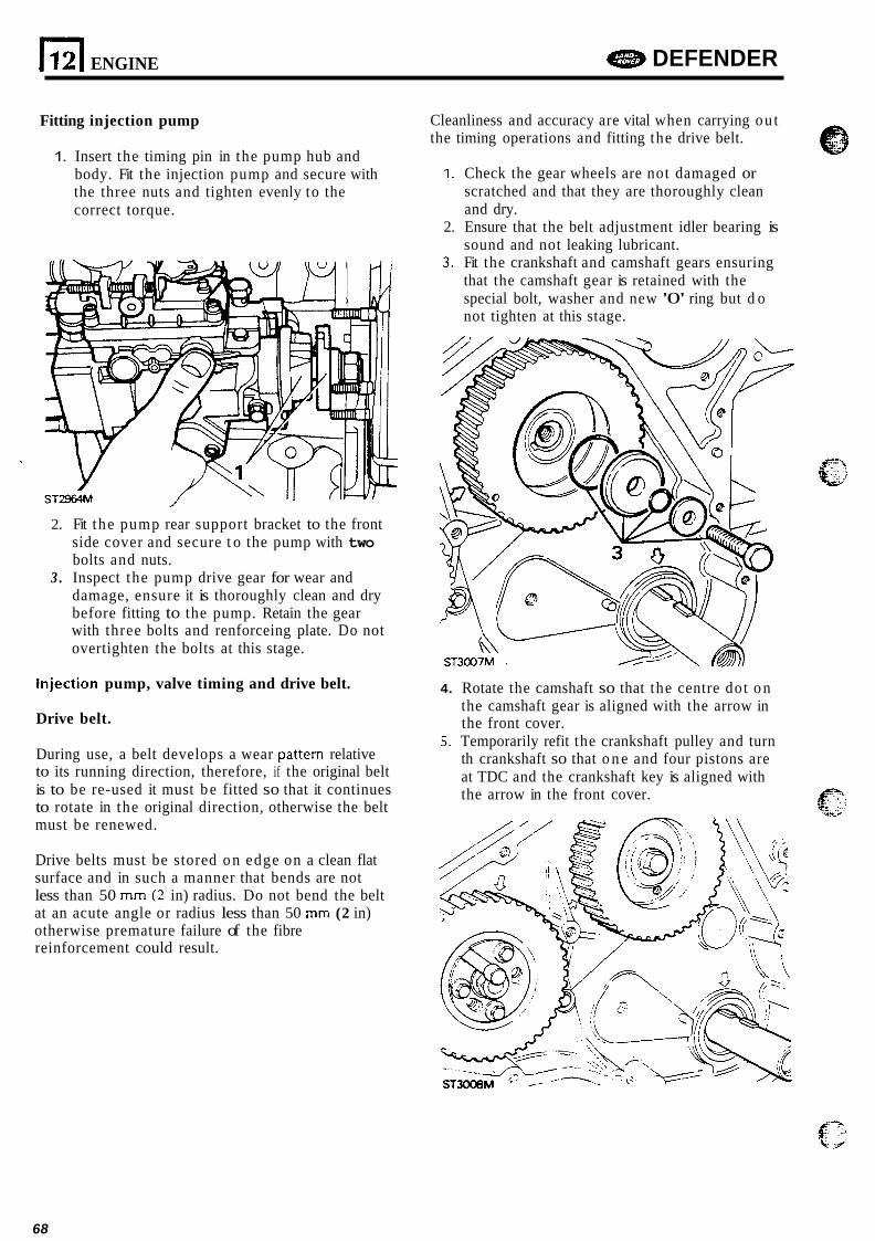
112) ENGINE e DEFENDER
Fitting injection pump
1. Insert the timing pin in the pump hub and body. Fit the injection pump and secure with the three nuts and tighten evenly to the correct torque.
2. Fit the pump rear support bracket to the front side cover and secure t o the pump with two bolts and nuts.
3 . Inspect the pump drive gear for wear and damage, ensure it is thoroughly clean and dry before fitting to the pump. Retain the gear with three bolts and renforceing plate. Do not overtighten the bolts at this stage.
Injection pump, valve timing and drive belt.
Drive belt.
During use, a belt develops a wear pattern relative to its running direction, therefore, if the original belt is to be re-used it must b e fitted so that it continues to rotate in the original direction, otherwise the belt must be renewed.
Cleanliness and accuracy are vital when carrying ou t the timing operations and fitting the drive belt.
1. Check the gear wheels are not damaged or scratched and that they are thoroughly clean and dry.
2. Ensure that the belt adjustment idler bearing is sound and not leaking lubricant.
3. Fit the crankshaft and camshaft gears ensuring that the camshaft gear is retained with the special bolt, washer and new '0' ring but d o not tighten at this stage.
4. Rotate the camshaft so that the centre dot o n the camshaft gear is aligned with the arrow in the front cover.
5. Temporarily refit the crankshaft pulley and turn th crankshaft so that o n e and four pistons are at TDC and the crankshaft key is aligned with the arrow in the front cover.
Drive belts must be stored o n edge on a clean flat surface and in such a manner that bends are not less than 50 mm ( 2 in) radius. Do not bend the belt at an acute angle or radius less than 50 mm (2 in) otherwise premature failure of the fibre reinforcement could result.
68

e DEFENDER ENGINE n 12
-_ 1 I :,,..,L l ’ , i
6. Screw the body of timing pin LST128 into the . \\ bottom of the flywheel housing and check that the pin will locate into the flywheel slot. It is important t o note that there are two slots in the flywheel and that the narrowest is the one that must b e used for this direct injection engine.
. %?
0
ST2641 M
Fitting and tensioning belt drive
Note: It is vitally important that t he following belt tensioning procedure it carried out carefully and accuratly. The procedure involves tensioning the belt twice. New a n d original delts a re tensioned t o different figures.
8. Ensure that the crankshaft, camshaft and in jection pump are correctly aligned then carefully fit the belt observing any rotational marks made during removal. Feed the delt over the gears keeping it tight on the drive side.
9. Fit the belt tensioner with the special washer and single bolt. Insert a 13 mm (0.5 in) square drive extension into the tensioner plate and with a dial type torque meter, apply a tension of 21.7 Nm (16 Lbf ft) for a new belt, or 16.3 Nm for an original belt. When the tension is correct and the meter is in the vertical position, tighten the clamp bolt.
Note: To ensu re correct belt tension it is very important tha t t h e tensioner is clamped when t h e t o rque meter is in the vertical position and t h e applied tension is correct.
10. Tighten the three bolts that secure the pump gear and reinforcing plate t o the pump hub t o the correct torque and remove the timing pin LSTI 2912.
CAUTION: Unlock t h e injection pump and fit the keeper plate before attempting t o turn the crankshaft. Also ensure that t h e flywheel timing pin LST128 is clear of t h e flywheel slot.
11. Rotate the crankshaft two complete revolutions and slacken the tensioner clamp bolt and tension the belt again, as previously described.
ST301 OM
69
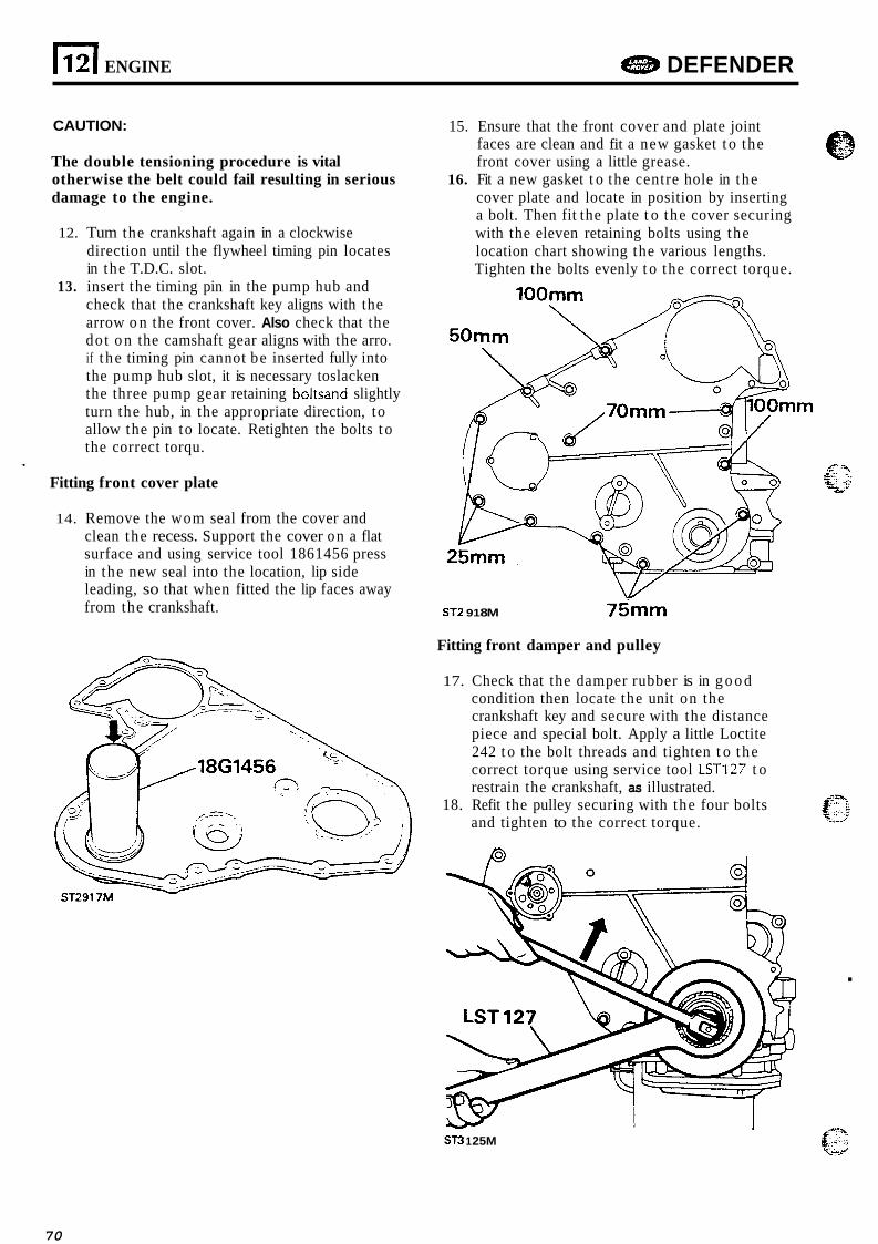
1 121 ENGINE DEFENDER
CAUTION:
The double tensioning procedure is vital otherwise the belt could fail resulting in serious damage to the engine.
12. Tum the crankshaft again in a clockwise direction until the flywheel timing pin locates in the T.D.C. slot.
check that the crankshaft key aligns with the arrow o n the front cover. Also check that the dot o n the camshaft gear aligns with the arro. if t he timing pin cannot be inserted fully into the pump hub slot, it is necessary toslacken the three pump gear retaining boltsand slightly turn the hub, in the appropriate direction, to allow the pin to locate. Retighten the bolts t o the correct torqu.
13. insert the timing pin in the pump hub and
Fitting front cover plate
14. Remove the wom seal from the cover and clean the recess. Support the cover on a flat surface and using service tool 1861456 press in the new seal into the location, lip side leading, so that when fitted the lip faces away from the crankshaft.
15. Ensure that the front cover and plate joint faces are clean and fit a new gasket t o the front cover using a little grease.
cover plate and locate in position by inserting a bolt. Then fit the plate t o the cover securing with the eleven retaining bolts using the location chart showing the various lengths. Tighten the bolts evenly t o the correct torque.
16. Fit a new gasket t o the centre hole in the
100"
ST2 91 8M 75" Fitting front damper and pulley
17. Check that the damper rubber is in g o o d condition then locate the unit on the crankshaft key and secure with the distance piece and special bolt. Apply a little Loctite 242 t o the bolt threads and tighten t o the correct torque using service tool LST127 t o restrain the crankshaft, as illustrated.
18. Refit the pulley securing with the four bolts and tighten to the correct torque.
.
ST3 1 25M
70
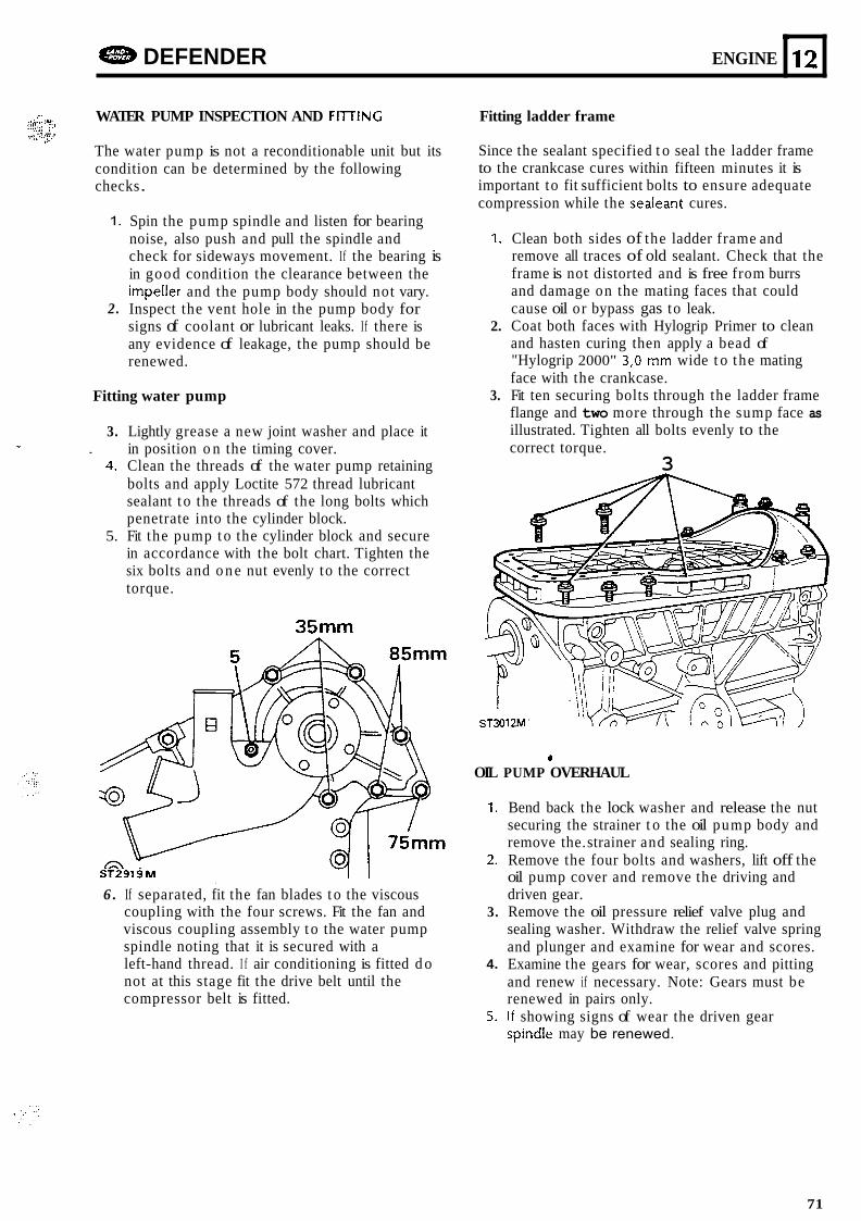
DEFENDER ENGINE
..,.,. 'i _.,. !-., ,& .. i:;.;:: :.i
WATER PUMP INSPECTION AND FllTlNC
The water pump is not a reconditionable unit but its condition can be determined by the following checks .
, . . .. ... .. ,::..::!..v I* ̂
L
12
1.
2.
Spin the pump spindle and listen for bearing noise, also push and pull the spindle and check for sideways movement. If the bearing is in good condition the clearance between the impeller and the pump body should not vary. Inspect the vent hole in the pump body for signs of coolant or lubricant leaks. If there is any evidence of leakage, the pump should be renewed.
Fitting water pump
3. Lightly grease a new joint washer and place it in position o n the timing cover.
4. Clean the threads of the water pump retaining bolts and apply Loctite 572 thread lubricant sealant t o the threads of the long bolts which penetrate into the cylinder block.
5. Fit the pump t o the cylinder block and secure in accordance with the bolt chart. Tighten the six bolts and o n e nut evenly to the correct torque.
- .
35"
6 . If separated, fit the fan blades t o the viscous coupling with the four screws. Fit the fan and viscous coupling assembly t o the water pump spindle noting that it is secured with a left-hand thread. I f air conditioning is fitted d o not at this stage fit the drive belt until the compressor belt is fitted.
Fitting ladder frame
Since the sealant specified t o seal the ladder frame to the crankcase cures within fifteen minutes it is important to fit sufficient bolts to ensure adequate compression while the sealeant cures.
1. Clean both sides of the ladder frame and remove all traces of old sealant. Check that the frame is not distorted and is free from burrs and damage on the mating faces that could cause oil or bypass gas to leak.
2. Coat both faces with Hylogrip Primer to clean and hasten curing then apply a bead of "Hylogrip 2000" 3,O mm wide t o the mating face with the crankcase.
3. Fit ten securing bolts through the ladder frame flange and two more through the sump face as illustrated. Tighten all bolts evenly to the correct torque.
3
ST3012M'
OIL
1.
2.
3.
4.
5.
* PUMP OVERHAUL
Bend back the lock washer and release the nut securing the strainer t o the oil pump body and remove the. strainer and sealing ring. Remove the four bolts and washers, lift off the oil pump cover and remove the driving and driven gear. Remove the oil pressure relief valve plug and sealing washer. Withdraw the relief valve spring and plunger and examine for wear and scores. Examine the gears for wear, scores and pitting and renew if necessary. Note: Gears must be renewed in pairs only. I f showing signs of wear the driven gear spind!e may be renewed.
71
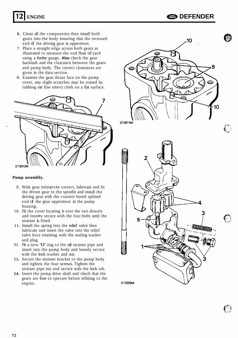
12 I ENGINE e DEFENDER J
6 . Clean all the components then install both '
gears into the body ensuring that the recessed end of the driving gear is uppermost.
7. Place a straight edge across both gears as illustrated t o measure the end float of each using a feeler gauge. Also check the gear backlash and the clearance between the gears and pump body. The correct clearances are given in the data section.
8. Examine the gear thrust face on the pump cover, any slight scratches may be erased by rubbing on fine emery cloth on a flat surface.
ST3014M
Pump assembly.
9. With gear tolorances correct, lubricate and fit the driven gear to the spindle and install the driving gear with the counter bored splined end of the gear uppermost in the pump housing.
10. Fit the cover locating it over the two dowels and loosley secure with the four bolts until the strainer is fitted.
11. Install the spring into the relief valve then lubricate and insert the valve into the relief valve bore retaining with the sealing washer and plug.
12. Fit a new '0' ring t o the oil strainer pipe and insert into the pump body and loosely secure with the lock washer and nut.
13 . Secure the strainer bracket t o the pump body and tighten the four screws. Tighten the strainer pipe nut and secure with the lock tab.
14. Insert the pump drive shaft and check that the gears are free to operate before refitting t o the engine.
72
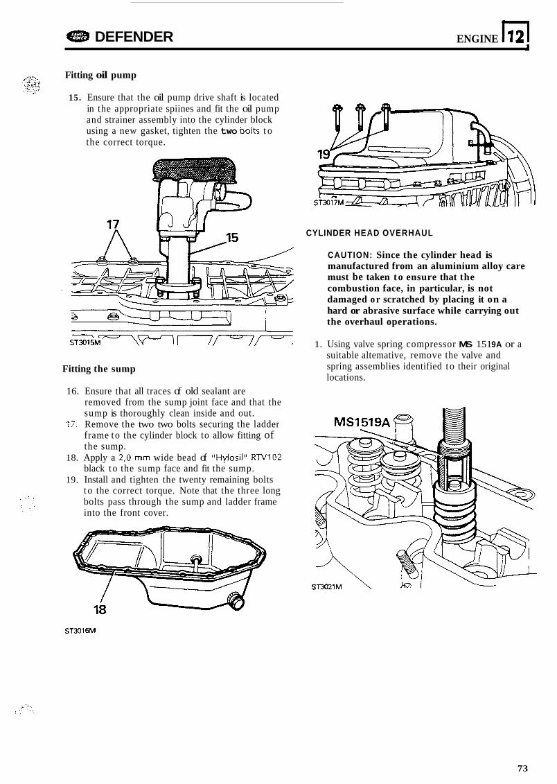
DEFENDER ENGINE n 12
Fitting oil pump
15. Ensure that the oil pump drive shaft is located in the appropriate spiines and fit the oil pump and strainer assembly into the cylinder block using a new gasket, tighten the two bolts t o the correct torque.
Fitting the sump
16. Ensure that all traces of old sealant are removed from the sump joint face and that the sump is thoroughly clean inside and out.
17. Remove the two two bolts securing the ladder frame t o the cylinder block to allow fitting of the sump.
18. Apply a 2,O mm wide bead of "Hylosil" RN102 black t o the sump face and fit the sump.
19. Install and tighten the twenty remaining bolts t o the correct torque. Note that the three long bolts pass through the sump and ladder frame into the front cover.
CYLINDER HEAD OVERHAUL
CAUTION: Since the cylinder head is manufactured from an aluminium alloy care must be taken to ensure that the combustion face, in particular, is not damaged o r scratched by placing it on a hard or abrasive surface while carrying out the overhaul operations.
1. Using valve spring compressor MS 151 9A or a suitable altemative, remove the valve and spring assemblies identified t o their original locations.
ST3016M
73

L
12
2. Discard the valve springs and valve guide oil seal. Remove carbon deposits from the valves and combustion chambers and degrease all parts ready for examination.
3. Examine the cylinder head for damage and distortio. Inspect the valve seat inserts for damage. Seat inserts that are beyond repair and require renewal should be replaced by a skilled specialist in this type of work.
4. Examine each valve guide and valve stem for wear and damage. Suspect guides should be checked by inserting a new valve into the guide and with the valve lifted approximatly 8 mm clear of the seat the valve head should not rock more than 0,15 mm (0.006 in). If the valve head movement exceeds 0,15 mm (0.006 in) the guide should be renewed.
5. inspect the valves for wear and damage. Valve heads that are burnt and cracked should be renewed. So should valves which are bent and distorted. Insert the valve into a new guide and check the side movement as described above to determine the wear o n the valve stem.
ENGINE DEFENDER
Renew valve guides
6. Support the cylinder head, combustion chamber uppermost o n pieces of timber of sufficient thickness to allow clearance for the inlet or exhaust for the valve guides to b e driven out using special tool R0274400.
.. . .
\ ST2598M
7. Turn the cylinder head over so that the combustion face is downwards. Lubricate the new valve guides and using special service tool LST 130 and depth gauge RO 60774A press the guide into position to the depth determined by the gmge d ?9,0 r r m (0.748 in).
Reface valve seat inserts
8.
9.
.c 1', The special se t of hand tools recommended
tightly into new or worn guides to ensure that the valve seat is concentric with the valve guide. The refacing tool has tungsten carbide cutters and can be used t o cut a new seat in the insert. The valve seat cutter is numbered MS621, the handle se t MS76B and the pilot
Loosely assemble the pilot in the sequence illustrated. Ensure that the chamfered end of the expander is towards the collet.
for refacing include expandable pilots that fit Q q.,
MS150-8.
U- ST2644M
74
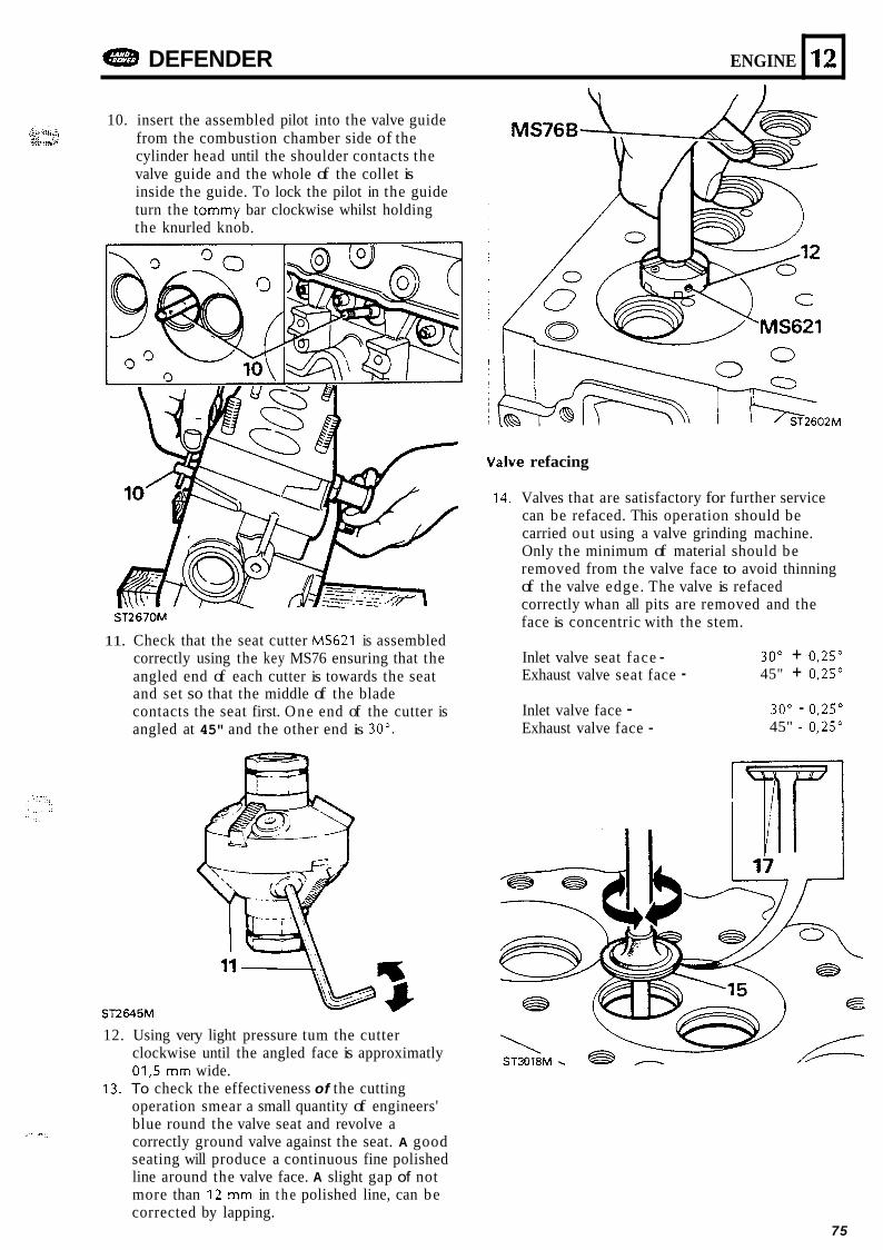
DEFENDER ENGINE
. I
r.. ;.. .L,._ ..U .;, 10. insert the assembled pilot into the valve guide
from the combustion chamber side of the cylinder head until the shoulder contacts the valve guide and the whole of the collet is inside the guide. To lock the pilot in the guide turn the tommy bar clockwise whilst holding the knurled knob.
,..._. ..,. 2 .i,....* .:,*, ,,.;. ....... .
12
Valve refacing
ST2670M
11. Check that the seat cutter MS621 is assembled correctly using the key MS76 ensuring that the angled end of each cutter is towards the seat and set so that the middle of the blade contacts the seat first. One end of the cutter is angled at 45" and the other end is 30".
ST2645M
12. Using very light pressure tum the cutter clockwise until the angled face is approximatly 01,s mm wide.
operation smear a small quantity of engineers' blue round the valve seat and revolve a correctly ground valve against the seat. A good seating will produce a continuous fine polished line around the valve face. A slight gap of not more than 12 mm in t h e polished line, can be corrected by lapping.
13. To check the effectiveness of the cutting
,, I.
14. Valves that are satisfactory for further service can be refaced. This operation should be carried out using a valve grinding machine. Only the minimum of material should be removed from the valve face to avoid thinning of the valve edge. The valve is refaced correctly whan all pits are removed and the face is concentric with the stem.
Inlet valve seat face - Exhaust valve seat face -
30" + 0,25" 45" + 0,25"
Inlet valve face - Exhaust valve face -
30" - 0,25" 45" - 0,25"
75
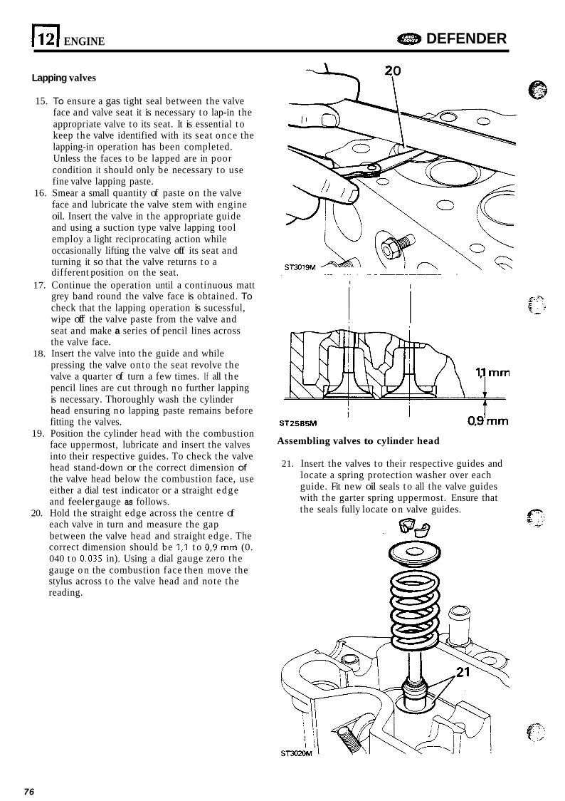
E[ ENGINE e DEFENDER
Lapping valves
15. To ensure a gas tight seal between the valve face and valve seat it is necessary t o lap-in the appropriate valve to its seat. It is essential t o keep the valve identified with its seat once the lapping-in operation has been completed. Unless the faces t o be lapped are in poor condition it should only be necessary to use fine valve lapping paste.
16. Smear a small quantity of paste on the valve face and lubricate the valve stem with engine oil. Insert the valve in the appropriate guide and using a suction type valve lapping tool employ a light reciprocating action while occasionally lifting the valve off its seat and turning it so that the valve returns t o a
. . .-. __ - . different position on the seat. -. - I 17. Continue the operation until a continuous matt I
grey band round the valve face is obtained. To check that the lapping operation is sucessful, wipe off the valve paste from the valve and ! I seat and make a series of pencil lines across the valve face.
18. Insert the valve into the guide and while pressing the valve onto the seat revolve the valve a quarter of turn a few times. If all the pencil lines are cut through no further lapping is necessary. Thoroughly wash the cylinder head ensuring n o lapping paste remains before fitting the valves.
19. Position the cylinder head with the combustion face uppermost, lubricate and insert the valves into their respective guides. To check the valve head stand-down or the correct dimension of the valve head below the combustion face, use either a dial test indicator or a straight edge and feeler gauge as follows.
20. Hold the straight edge across the centre of each valve in turn and measure the gap between the valve head and straight edge. The correct dimension should be 1,l t o 0,9 mm (0. 040 t o 0.035 in). Using a dial gauge zero the gauge o n the combustion face then move the stylus across t o the valve head and note the reading.
ST2585M
Assembling valves to cylinder head
21. Insert the valves to their respective guides and locate a spring protection washer over each guide. Fit new oil seals t o all the valve guides with the garter spring uppermost. Ensure that the seals fully locate o n valve guides.
76
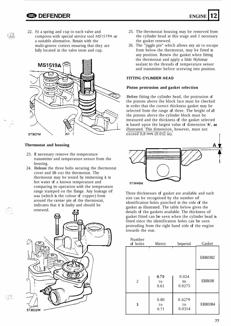
e DEFENDER ENGINE
. ... . 22. Fit a spring and cup to each valve and compress with special service tool MS1519A or a suitable altemative. Retain with the multi-groove cotters ensuring that they are fully located in the valve stem and cup.
L. ;:.:it .. . . . . . . '.::::Y:.. ., ..., . ..
12
Thermostat and housing
0.70
0.61 2 t o
0.80
0.71 3 t o
23. If necessary remove the temperature transmitter and temperature sensor from the housing.
24. Release the three bolts securing the thermostat cover and lift ou t the thermostat. The thermostat may be tested by immersing it in hot water of a known temperature and comparing its operation with the temperature range stamped on the flange. Any leakage of wax (which is the colour of copper) from around the center pin of the thermostat, indicates that it is faulty and should be renewed. n
0.024 to
0.0275
0.0279 t o
0.0314 ST3022M
25. The thermostat housing may be removed from the cylinder head at this stage and if necessary the gasket renewed.
26. The "jiggle pin" which allows any air t o escape from below the thermostat, may b e fitted in any position. Renew the gasket when fitting the thermostat and apply a little Hylomar sealant to the threads of temperature sensor and transmitter before screwing into position.
FITTING CYLINDER HEAD
Piston protrusion and gasket selection
Before fitting the cylinder head, the protrusion of the pistons above the block face must be checked in order that the correct thickness gasket may be selected from the range of three. The height of all the pistons above the cylinder block must be measured and the thickness of the gasket selected is based upon the largest value of dimension 'A', as illustrated. This dimension, however, must not exceed 0,8 mm (0.032 in).
- _. _- -
Al ST2646M
Three thicknesses of gasket are available and each size can be recognised by the number of identification holes punched in the side of the gasket as illustrated. The table below gives the details of the gaskets available. The thickness of gasket fitted can be seen when the cylinder head is fitted since the identification holes can be seen protruding from the right hand side of the engine towards the rear.
Number of holes Metric Imperial
I I Gasket
ERR0382
~
ERR038
ERR0384
77
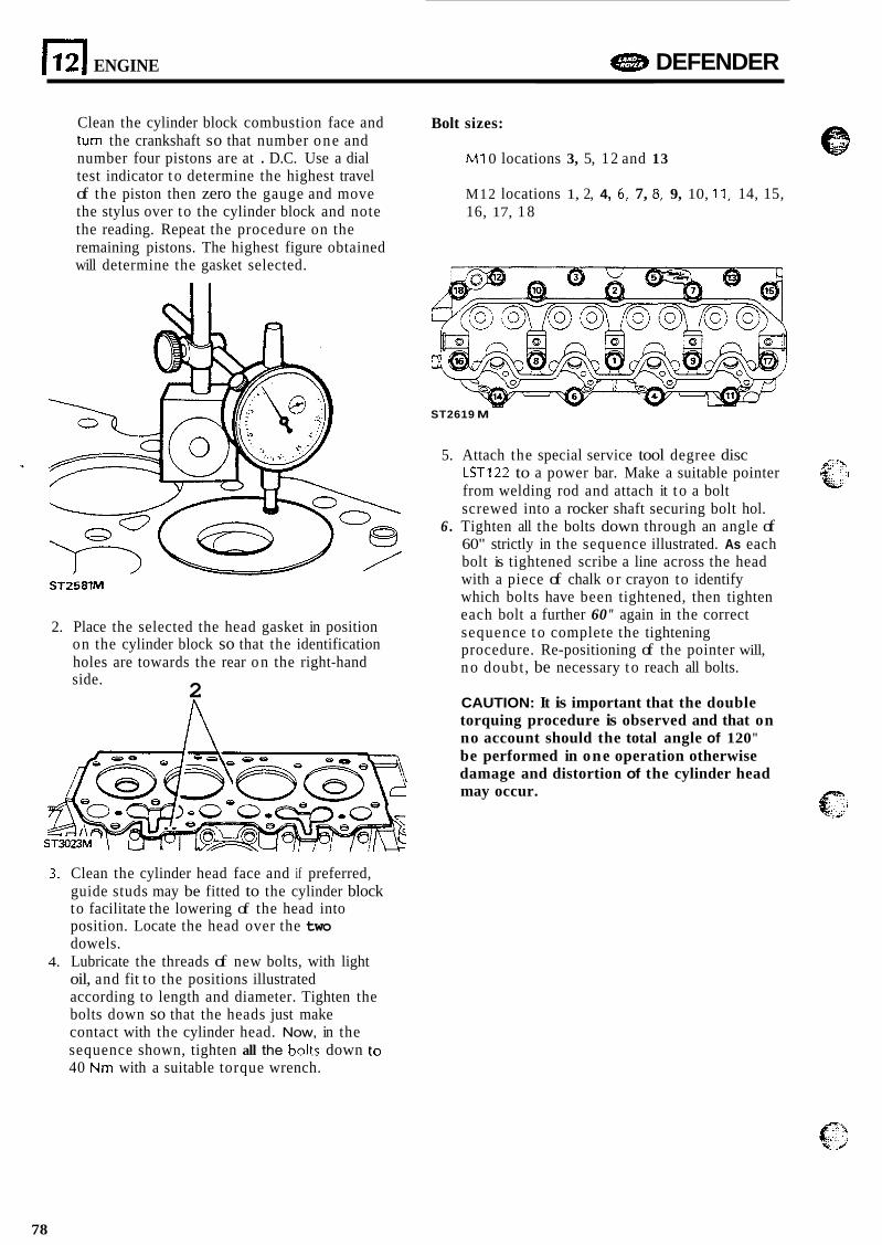
ENGINE e DEFENDER
Clean the cylinder block combustion face and turn the crankshaft so that number one and number four pistons are at . D.C. Use a dial test indicator t o determine the highest travel of the piston then zero the gauge and move the stylus over to the cylinder block and note the reading. Repeat the procedure on the remaining pistons. The highest figure obtained will determine the gasket selected.
ST2581M
2. Place the selected the head gasket in position on the cylinder block so that the identification holes are towards the rear o n the right-hand side. 2
3. Clean the cylinder head face and if preferred, guide studs may be fitted to the cylinder block to facilitate the lowering of the head into position. Locate the head over the two dowels.
oil, and fit to the positions illustrated according to length and diameter. Tighten the bolts down so that the heads just make contact with the cylinder head. Now, in the sequence shown, tighten all the holtr down tc! 40 Nm with a suitable torque wrench.
4. Lubricate the threads of new bolts, with light
Bolt sizes:
M1 0 locations 3, 5, 12 and 13
M12 locations 1, 2, 4, 6: 7, 8, 9, 10, 1 I i 14, 15, 16, 17, 1 8
ST2619 M
5. Attach the special service tool degree disc LST122 to a power bar. Make a suitable pointer from welding rod and attach it t o a bolt screwed into a rocker shaft securing bolt hol.
6 . Tighten all the bolts down through an angle of 60" strictly in the sequence illustrated. As each bolt is tightened scribe a line across the head with a piece of chalk o r crayon to identify which bolts have been tightened, then tighten each bolt a further 60" again in the correct sequence t o complete the tightening procedure. Re-positioning of the pointer will, n o doubt, be necessary t o reach all bolts.
CAUTION: It is important that the double torquing procedure is observed and that on no account should the total angle of 120" be performed in one operation otherwise damage and distortion of the cylinder head may occur.
78
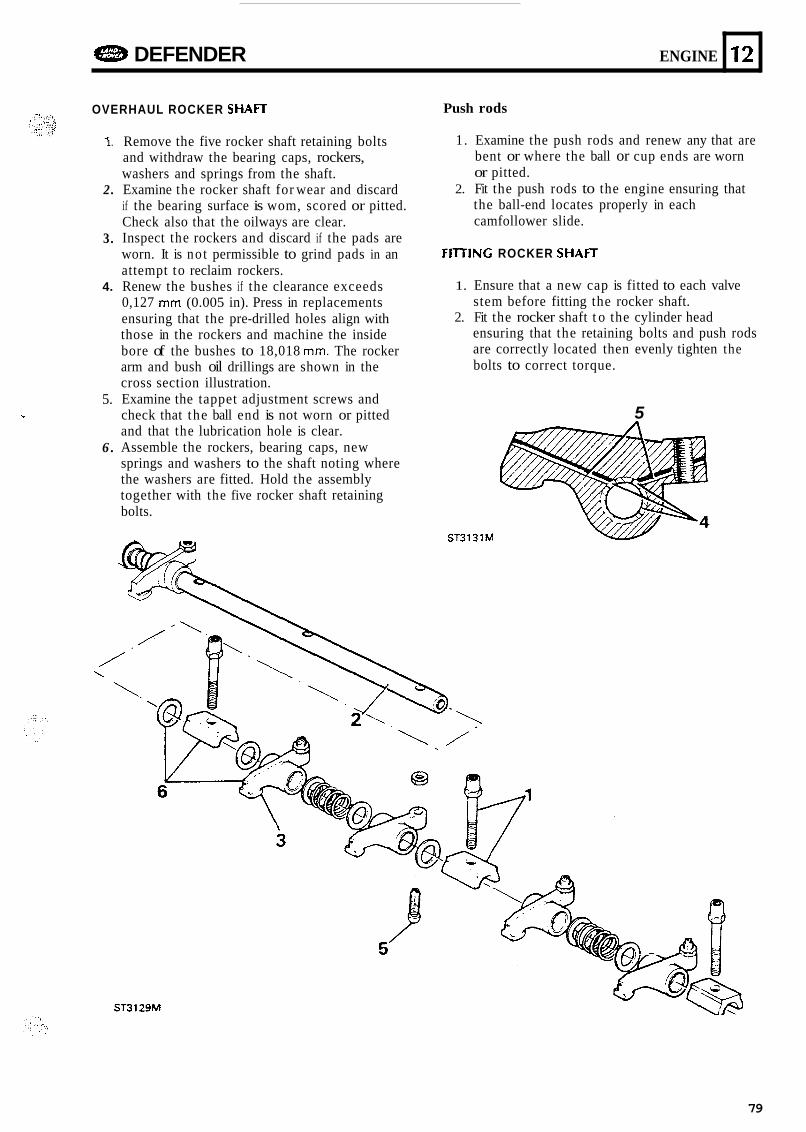
4!83 DEFENDER ENGINE
OVERHAUL ROCKER S H A n
12
1 .
2.
3.
4.
5. *
6 .
Remove the five rocker shaft retaining bolts and withdraw the bearing caps, rockers, washers and springs from the shaft. Examine the rocker shaft for wear and discard if the bearing surface is wom, scored or pitted. Check also that the oilways are clear. Inspect the rockers and discard if the pads are worn. It is no t permissible to grind pads in an attempt to reclaim rockers. Renew the bushes if the clearance exceeds 0,127 mm (0.005 in). Press in replacements ensuring that the pre-drilled holes align with those in the rockers and machine the inside bore of the bushes to 18,018 mm. The rocker arm and bush oil drillings are shown in the cross section illustration. Examine the tappet adjustment screws and check that the ball end is not worn or pitted and that the lubrication hole is clear. Assemble the rockers, bearing caps, new springs and washers to the shaft noting where the washers are fitted. Hold the assembly together with the five rocker shaft retaining bolts.
Push rods
1. Examine the push rods and renew any that are bent or where the ball or cup ends are worn or pitted.
2. Fit the push rods to the engine ensuring that the ball-end locates properly in each camfollower slide.
FlITlNG ROCKER S H A I T
1. Ensure that a new cap is fitted to each valve stem before fitting the rocker shaft.
2. Fit the rocker shaft t o the cylinder head ensuring that the retaining bolts and push rods are correctly located then evenly tighten the bolts to correct torque.
5
ST3131M
ST3129M
79
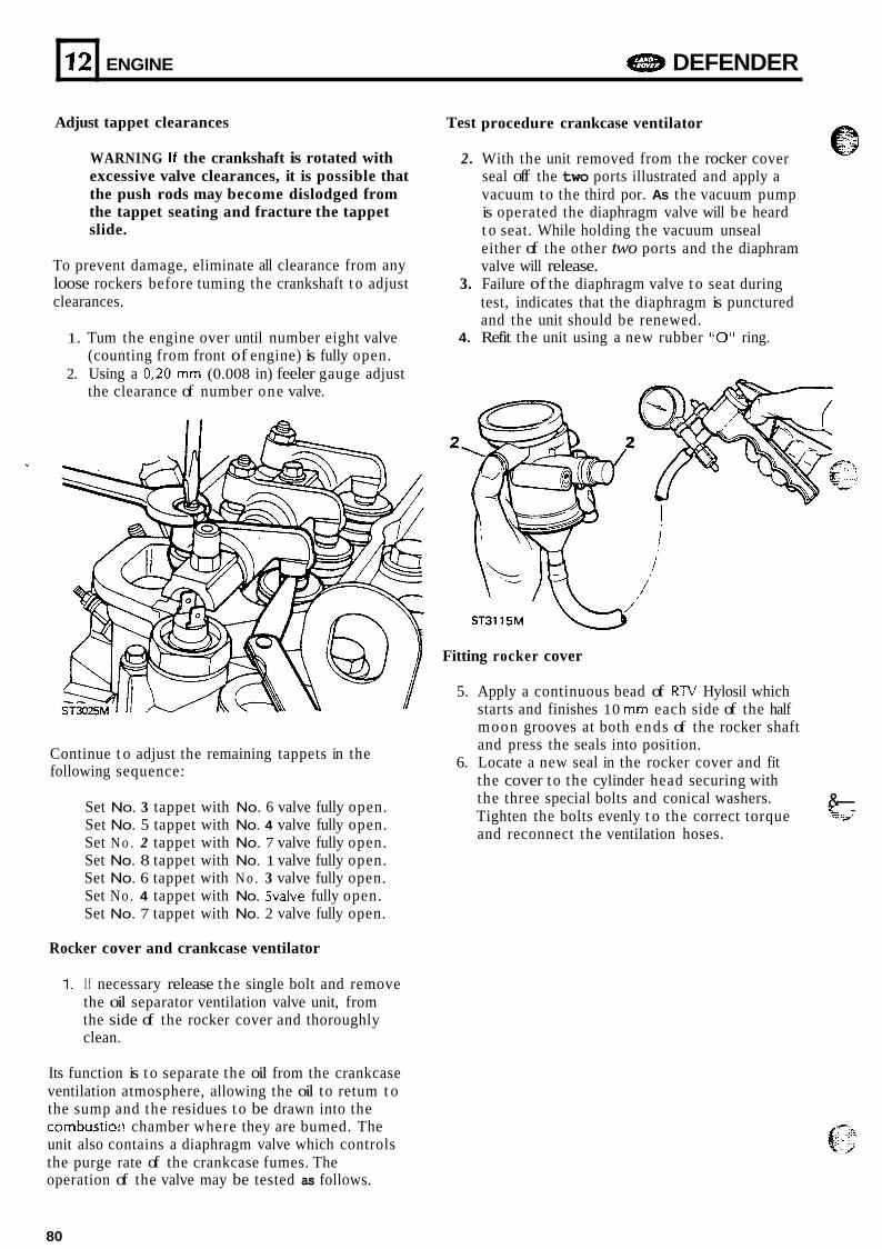
. 12
Adjust tappet clearances
ENGINE a DEFENDER
WARNING If the crankshaft is rotated with excessive valve clearances, it is possible that the push rods may become dislodged from the tappet seating and fracture the tappet slide.
To prevent damage, eliminate all clearance from any loose rockers before tuming the crankshaft t o adjust clearances.
1. Tum the engine over until number eight valve (counting from front of engine) is fully open.
2. Using a 0,20 mm (0.008 in) feeler gauge adjust the clearance of number one valve.
Continue t o adjust the remaining tappets in the following sequence:
Set No. 3 tappet with No. 6 valve fully open. Set No. 5 tappet with No. 4 valve fully open. Set N o . 2 tappet with No. 7 valve fully open. Set No. 8 tappet with No. 1 valve fully open. Set No. 6 tappet with N o . 3 valve fully open. Set No. 4 tappet with No. 5valve fully open. Set No. 7 tappet with No. 2 valve fully open.
Rocker cover and crankcase ventilator
7. I f necessary release the single bolt and remove the oil separator ventilation valve unit, from the side of the rocker cover and thoroughly clean.
Its function is t o separate the oil from the crankcase ventilation atmosphere, allowing the oil to retum t o the sump and the residues t o be drawn into the combustio:! chamber where they are bumed. The unit also contains a diaphragm valve which controls the purge rate of the crankcase fumes. The operation of the valve may be tested as follows.
Test
2.
procedure crankcase ventilator
With the unit removed from the rocker cover seal off the two ports illustrated and apply a vacuum to the third por. As the vacuum pump is operated the diaphragm valve will be heard t o seat. While holding the vacuum unseal either of the other two ports and the diaphram valve will release.
test, indicates that the diaphragm is punctured and the unit should be renewed.
3. Failure of the diaphragm valve t o seat during
4. Refit the unit using a new rubber "0" ring.
Fitting rocker cover
5. Apply a continuous bead of RW Hylosil which starts and finishes 10 mm each side of the half moon grooves at both ends of the rocker shaft and press the seals into position.
6. Locate a new seal in the rocker cover and fit the cover to the cylinder head securing with the three special bolts and conical washers. Tighten the bolts evenly t o the correct torque
&- E ."-*I "
and reconnect the ventilation hoses.
80
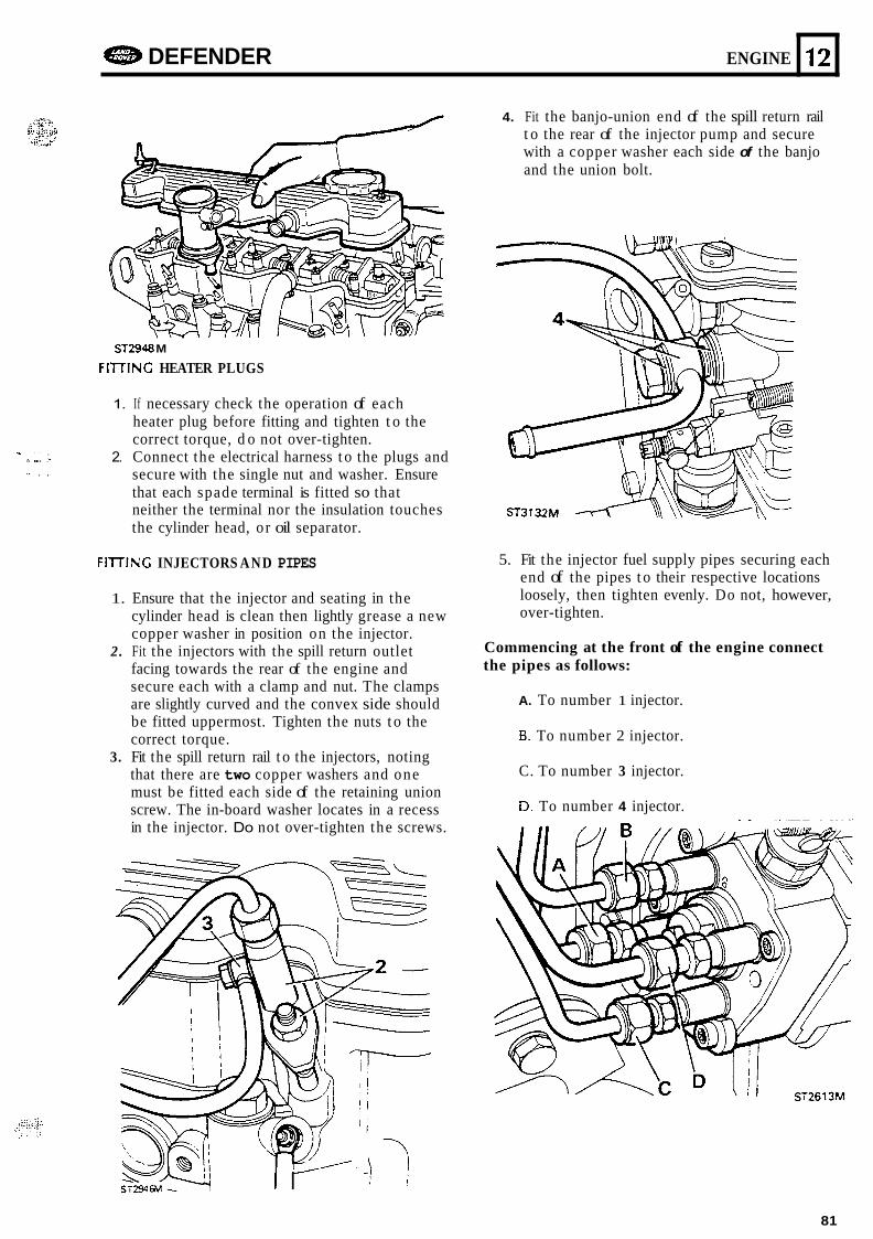
- -.. . . .. ..,.. , . ... .. , ,
42%D DEFENDER ENGINE 12
n
ST2948 M
FIITlNG HEATER PLUGS
1.
2.
If necessary check the operation of each heater plug before fitting and tighten t o the correct torque, d o not over-tighten. Connect the electrical harness t o the plugs and secure with the single nut and washer. Ensure that each spade terminal is fitted so that neither the terminal nor the insulation touches the cylinder head, or oil separator.
FllTlNG INJECTORS AND PIPES
1. Ensure that the injector and seating in the cylinder head is clean then lightly grease a new copper washer in position on the injector.
2. Fit the injectors with the spill return outlet facing towards the rear of the engine and secure each with a clamp and nut. The clamps are slightly curved and the convex side should be fitted uppermost. Tighten the nuts t o the correct torque.
3. Fit the spill return rail t o the injectors, noting that there are two copper washers and one must be fitted each side of the retaining union screw. The in-board washer locates in a recess in the injector. Do not over-tighten the screws.
4. Fit the banjo-union end of the spill return rail t o the rear of the injector pump and secure with a copper washer each side of the banjo and the union bolt.
5. Fit the injector fuel supply pipes securing each end of the pipes t o their respective locations loosely, then tighten evenly. Do not, however, over-tighten.
Commencing at the front of the engine connect the pipes as follows:
A. To number 1 injector.
B. To number 2 injector.
C. To number 3 injector.
D. To number 4 injector.
81
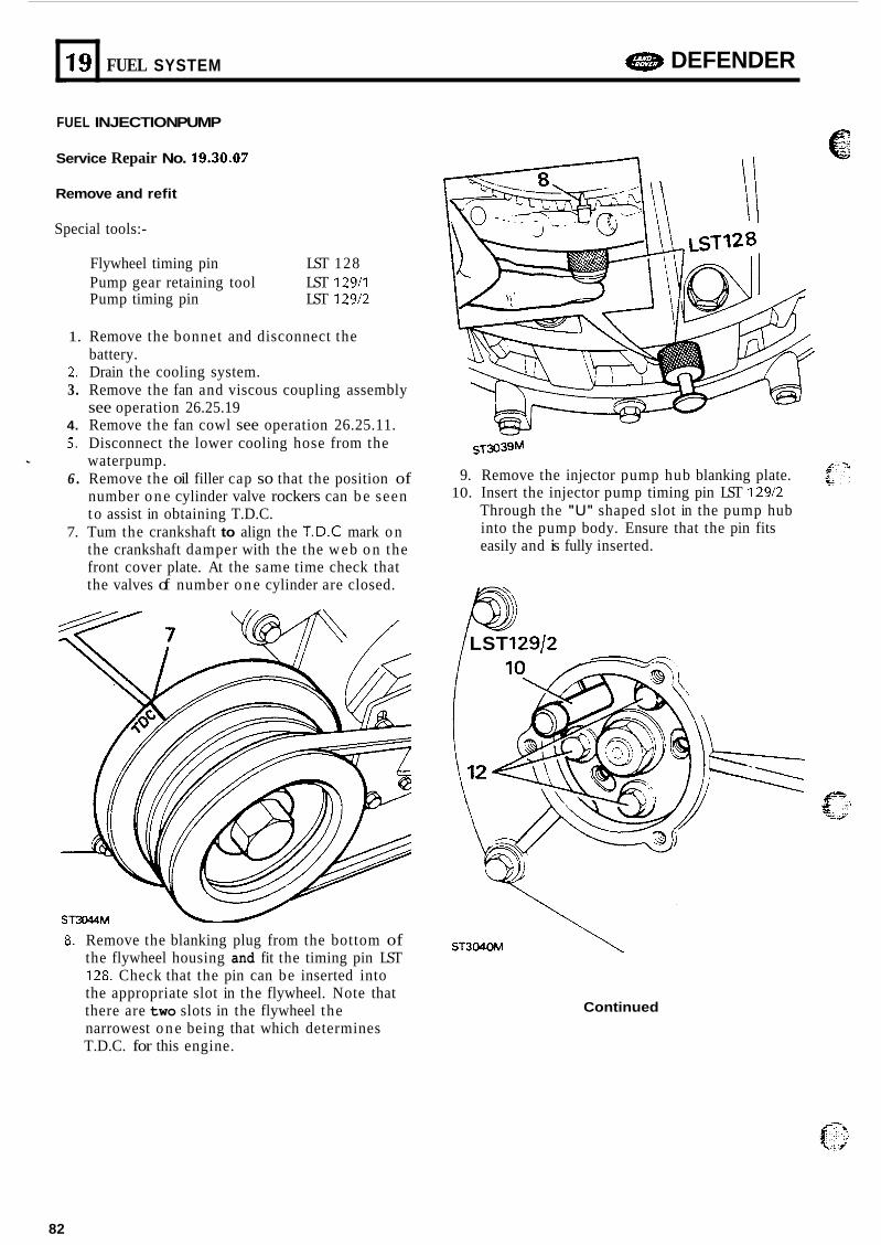
a DEFENDER 19 FUEL SYSTEM ...
FUEL INJECTION PUMP
Service Repair No. 19.30.07
Remove and refit
Special tools:-
Flywheel timing pin LST 128 Pump gear retaining tool LST 12911 Pump timing pin LST 12912
1. Remove the bonnet and disconnect the battery.
2. Drain the cooling system. 3. Remove the fan and viscous coupling assembly
see operation 26.25.19 4. Remove the fan cowl see operation 26.25.11. 5. Disconnect the lower cooling hose from the
waterpump. 6 . Remove the oil filler cap so that the position of
number o n e cylinder valve rockers can b e seen t o assist in obtaining T.D.C.
7. Tum the crankshaft to align the T.D.C mark o n the crankshaft damper with the the web o n the front cover plate. At the same time check that the valves of number o n e cylinder are closed.
ST3044M
8. Remove the blanking plug from the bottom of the flywheel housing and fit the timing pin LST 128. Check that the pin can be inserted into the appropriate slot in the flywheel. Note that there are two slots in the flywheel the narrowest o n e being that which determines T.D.C. for this engine.
9. Remove the injector pump hub blanking plate.
Through the "U" shaped slot in the pump hub into the pump body. Ensure that the pin fits easily and is fully inserted.
10. Insert the injector pump timing pin LST 12912
/ LST 129/2
Continued
82
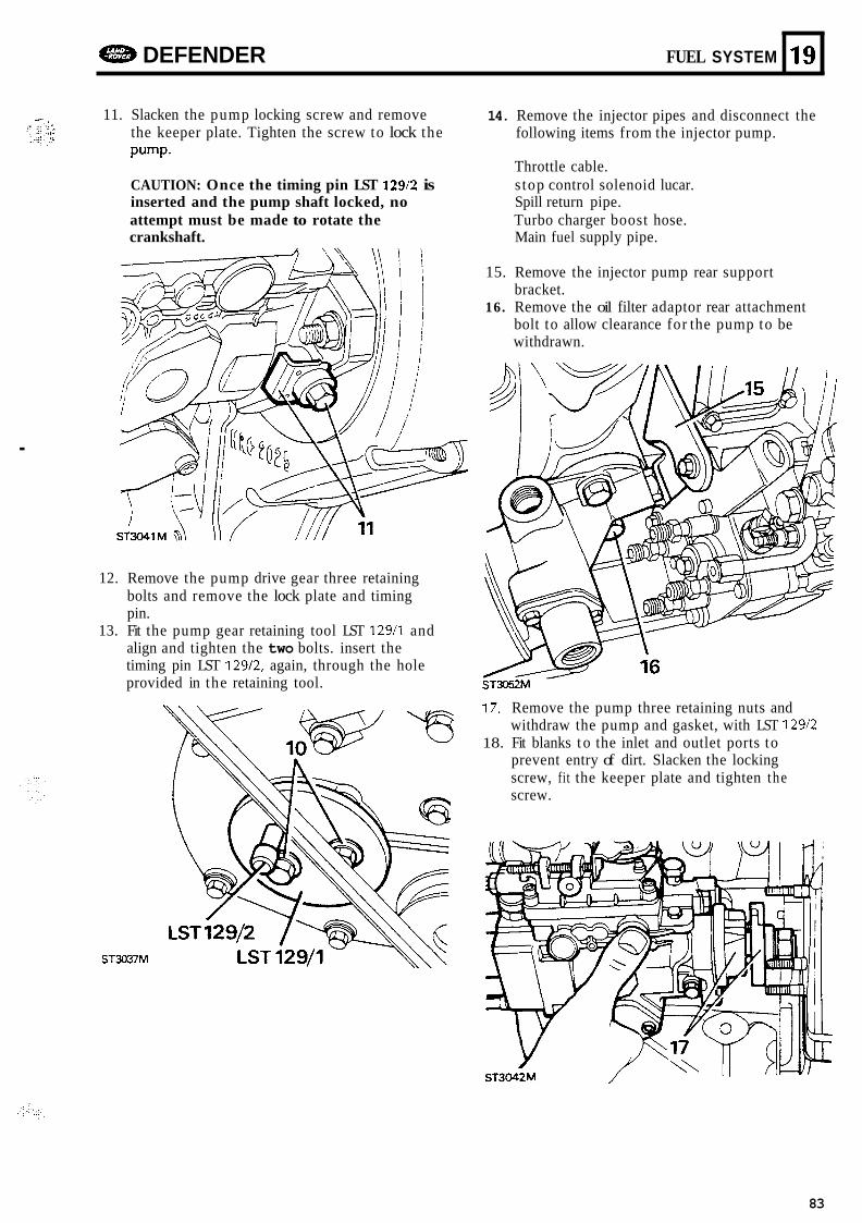
e DEFENDER FUEL SYSTEM
11. Slacken the pump locking screw and remove 14. Remove the injector pipes and disconnect the the keeper plate. Tighten the screw to lock the pump.
CAUTION: Once the timing pin LST 129/2 is inserted and the pump shaft locked, no attempt must be made to rotate the crankshaft. Main fuel supply pipe.
following items from the injector pump.
Throttle cable. s top control solenoid lucar. Spill return pipe. Turbo charger boost hose.
19
.
12. Remove the pump drive gear three retaining bolts and remove the lock plate and timing pin.
13. Fit the pump gear retaining tool LST 129/1 and align and tighten the two bolts. insert the timing pin LST 129/2, again, through the hole provided in the retaining tool.
ST3037M
15. Remove the injector pump rear support bracket.
16. Remove the oil filter adaptor rear attachment bolt to allow clearance for the pump to be withdrawn.
17. Remove the pump three retaining nuts and withdraw the pump and gasket, with LST 12912
18. Fit blanks t o the inlet and outlet ports to prevent entry of dirt. Slacken the locking screw, fit the keeper plate and tighten the screw.
83
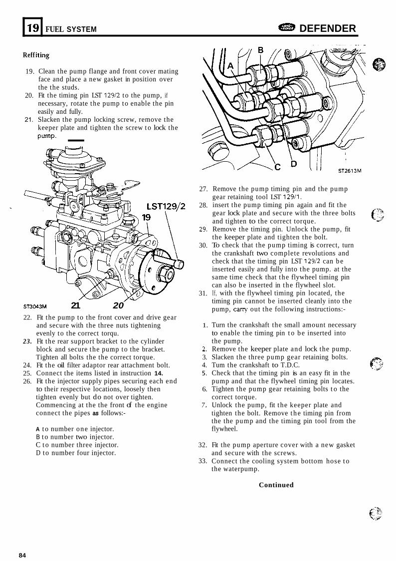
19
Reff iting
FUEL SYSTEM DEFENDER
19.
20.
21.
Clean the pump flange and front cover mating face and place a new gasket in position over the the studs. Fit the timing pin LST 129/2 to the pump, if necessary, rotate the pump to enable the pin easily and fully. Slacken the pump locking screw, remove the keeper plate and tighten the screw t o lock the pump- -
ST3043M 21 20 22.
23.
24. 25. 26.
Fit the pump to the front cover and drive gear and secure with the three nuts tightening evenly to the correct torqu. Fit the rear support bracket to the cylinder block and secure the pump to the bracket. Tighten all bolts the the correct torque. Fit the oil filter adaptor rear attachment bolt. Connect the items listed in instruction 14. Fit the injector supply pipes securing each end to their respective locations, loosely then tighten evenly but do not over tighten. Commencing at the the front of the engine connect the pipes as follows:-
A t o number one injector. B t o number two injector. C t o number three injector. D to number four injector.
27.
28.
29.
30.
31.
1.
2. 3. 4. 5.
6.
7.
32.
33.
Remove the pump timing pin and the pump gear retaining tool LST 129/1. insert the pump timing pin again and fit the gear lock plate and secure with the three bolts and tighten to the correct torque. Remove the timing pin. Unlock the pump, fit the keeper plate and tighten the bolt. To check that the pump timing is correct, turn the crankshaft two complete revolutions and check that the timing pin LST 129/2 can b e inserted easily and fully into the pump. at the same time check that t he flywheel timing pin can also b e inserted in t he flywheel slot. If, with the flywheel timing pin located, the timing pin cannot be inserted cleanly into the pump, carry out the following instructions:-
Turn the crankshaft the small amount necessary to enable the timing pin t o b e inserted into the pump. Remove the keeper plate and lock the pump. Slacken the three pump gear retaining bolts. Tum the crankshaft to T.D.C. Check that the timing pin is an easy fit in the pump and that the flywheel timing pin locates. Tighten the pump gear retaining bolts t o the correct torque. Unlock the pump, fit the keeper plate and tighten the bolt. Remove t h e timing pin from the the pump and the timing pin tool from the flywheel.
Fit the pump aperture cover with a new gasket and secure with the screws. Connect the cooling system bottom hose t o the waterpump.
Continued
84
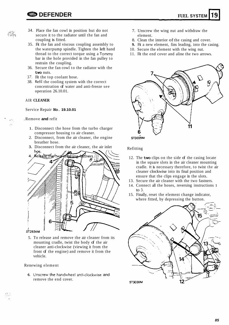
-- /p:+ ,::- ,” .. ..... . , ...... , ,,.... ~: . . .
e DEFENDER FUEL SYSTEM 119 I 34. Place the fan cowl in position but do not
secure it t o the radiator until the fan and coupling is fitted.
35. Fit the fan and viscous coupling assembly to the waterpump spindle. Tighten the left hand thread to the correct torque using a Tommy bar in the hole provided in the fan pulley t o restrain the coupling.
36. Secure the fan cowl t o the radiator with the two nuts.
37. Fit the top coolant hose. 38. Refil the cooling system with the correct
concentration of water and anti-freeze s ee operation 26.10.01.
AIR CLEANER
Service Repair No. 19.10.01
. Remove and refit
1. Disconnect the hose from the turbo charger compressor housing t o air cleaner.
2. Disconnect, from the air cleaner, the engine breather hose.
3. Disconnect from the air cleaner, the air inlet
5. To release and remove the air cleaner from its mounting cradle, twist the body of the air cleaner anti-clockwise (viewing it from the front of the engine) and remove it from the vehicle.
Renewing e lement
6 . Unscrew t h e handwhee! anti-c!nckwise and remove the end cover.
7. Unscrew the wing nut and withdraw the
8. Clean the interior of the casing and cover. 9. Fit a new element, fins leading, into the casing.
10. Secure the element with the wing nut. 11. Fit the end cover and aline the two arrows.
element.
Refitting
12. The two clips on the side of the casing locate in the square slots in the air cleaner mounting cradle. It is necessary therefore, t o twist t he air cleaner clockwise into its final position and ensure that the clips engage in the slots.
13. Secure the air cleaner with the two fastners. 14. Connect all the hoses, reversing instructions 1
to 3. 15. Finally, reset the element change indicator,
where fitted, by depressing the button.
ST3036M 12’
85
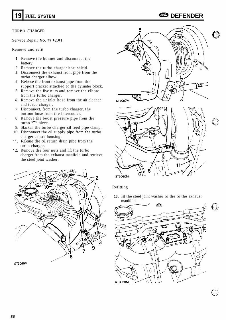
19
TURBO CHARGER
FUEL SYSTEM DEFENDER
Service Repair No. 19.42.01
Remove and refit
1. Remove the bonnet and disconnect the battery.
2. Remove the turbo charger heat shield. 3. Disconnect the exhaust front pipe from the
turbo charger elbow. 4. Release the front exhaust pipe from the
support bracket attached t o the cylinder block. 5. Remove the five nuts and remove the elbow
from the turbo charger. 6 . Remove the air inlet hose from the air cleaner
and turbo charger. 7. Disconnect, from the turbo charger, the
bottom hose from the intercooler. 8. Remove the boost pressure pipe from the
turbo "T" piece. 9. Slacken the turbo charger oil feed pipe clamp.
10. Disconnect the oil supply pipe from the turbo charger centre housing.
11. Release the oil return drain pipe from the turbo charger.
12. Remove the four nuts and lift the turbo charger from the exhaust manifold and retrieve the steel joint washer.
Refitting
13. Fit the steel joint washer to the t o the exhaust manifold
e , .: '.'
86
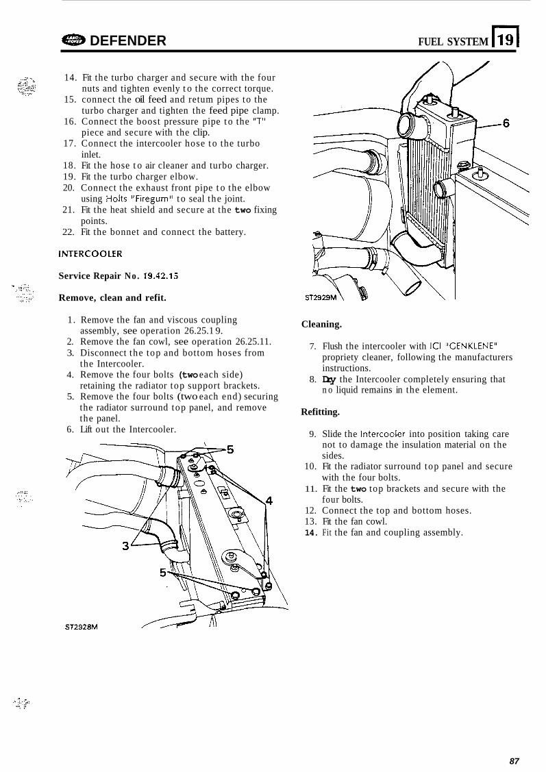
..1:;:: . . . . , . > . : . ,. . ... . .
Gl%B DEFENDER FUEL SYSTEM
14. Fit the turbo charger and secure with the four nuts and tighten evenly t o the correct torque.
15. connect the oil feed and retum pipes to the turbo charger and tighten the feed pipe clamp.
16. Connect the boost pressure pipe t o the "T" piece and secure with the clip.
17. Connect the intercooler hose t o the turbo inlet.
18. Fit the hose t o air cleaner and turbo charger. 19. Fit the turbo charger elbow. 20. Connect the exhaust front pipe t o the elbow
using Holts "Firegum" t o seal the joint. 21. Fit the heat shield and secure at the two fixing
points. 22. Fit the bonnet and connect the battery.
INTERCOOLER
Service Repair No . 19.42.15
Remove, clean and refit.
1. Remove the fan and viscous coupling assembly, see operation 26.25.1 9.
2. Remove the fan cowl, see operation 26.25.11. 3. Disconnect the top and bottom hoses from
the Intercooler. 4. Remove the four bolts (two each side)
retaining the radiator top support brackets. 5. Remove the four bolts (two each end) securing
the radiator surround top panel, and remove the panel.
6. Lift out the Intercooler.
ST2928M
Cleaning.
7. Flush the intercooler with ICI "GENKLENE" propriety cleaner, following the manufacturers instructions.
n o liquid remains in the element. 8. Dry the Intercooler completely ensuring that
Refitting.
9. Slide the htercooler into position taking care not to damage the insulation material on the sides.
10. Fit the radiator surround top panel and secure with the four bolts.
11. Fit the two top brackets and secure with the four bolts.
12. Connect the top and bottom hoses. 13. Fit the fan cowl. 14. Fit the fan and coupling assembly.
I .i . :. .$! . .. . !, ...
87
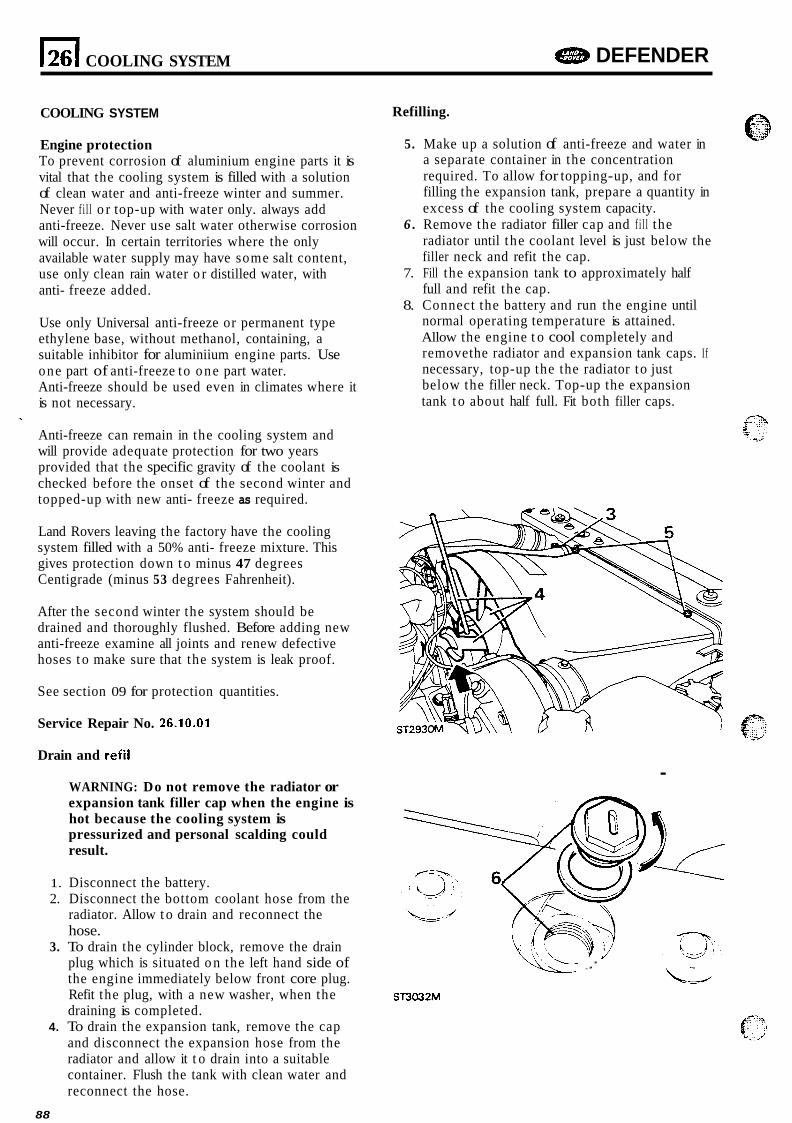
COOLING SYSTEM DEFENDER
COOLING SYSTEM
Engine protection To prevent corrosion of aluminium engine parts it is vital that the cooling system is filled with a solution of clean water and anti-freeze winter and summer. Never f i l l o r top-up with water only. always add anti-freeze. Never use salt water otherwise corrosion will occur. In certain territories where the only available water supply may have some salt content, use only clean rain water o r distilled water, with anti- freeze added.
Use only Universal anti-freeze or permanent type ethylene base, without methanol, containing, a suitable inhibitor for aluminiium engine parts. Use one part of anti-freeze to one part water. Anti-freeze should be used even in climates where it is not necessary.
Anti-freeze can remain in the cooling system and will provide adequate protection for two years provided that the specific gravity of the coolant is checked before the onset of the second winter and topped-up with new anti- freeze as required.
Land Rovers leaving the factory have the cooling system filled with a 50% anti- freeze mixture. This gives protection down t o minus 47 degrees Centigrade (minus 53 degrees Fahrenheit).
After the second winter the system should be drained and thoroughly flushed. Before adding new anti-freeze examine all joints and renew defective hoses t o make sure that the system is leak proof.
See section 09 for protection quantities.
Service Repair No. 26.10.01
Refilling.
5. Make up a solution of anti-freeze and water in a separate container in the concentration required. To allow for topping-up, and for filling the expansion tank, prepare a quantity in excess of the cooling system capacity.
6 . Remove the radiator filler cap and f i l l the radiator until the coolant level is just below the filler neck and refit the cap.
7. Fill the expansion tank to approximately half full and refit the cap.
8. Connect the battery and run the engine until normal operating temperature is attained. Allow the engine t o cool completely and removethe radiator and expansion tank caps. If necessary, top-up the the radiator to just below the filler neck. Top-up the expansion tank t o about half full. Fit both filler caps.
Drain and refil .
WARNING: Do not remove the radiator or expansion tank filler cap when the engine is hot because the cooling system is pressurized and personal scalding could result.
1. Disconnect the battery. 2. Disconnect the bottom coolant hose from the
radiator. Allow t o drain and reconnect the hose.
3. To drain the cylinder block, remove the drain plug which is situated o n the left hand side of the engine immediately below front core plug. Refit the plug, with a new washer, when the draining is completed.
4. To drain the expansion tank, remove the cap and disconnect the expansion hose from the radiator and allow it t o drain into a suitable container. Flush the tank with clean water and reconnect the hose.
\ - \- _,’
ST3032M
88
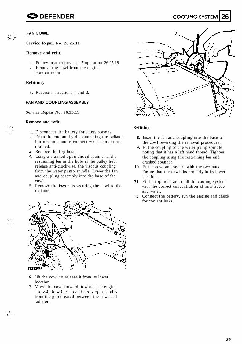
G83 DEFENDER COOLING SYSTEM
FAN COWL
26
Service Repair No. 26.25.11
Remove and refit.
1. Follow instructions 1 t o 7 operation 26.25.19. 2. Remove the cowl from the engine
compartment.
Refitting.
3. Reverse instructions 1 and 2.
FAN AND COUPLING ASSEMBLY
Service Repair No. 26.25.19
Remove and refit.
1. Disconnect the battery for safety reasons. 2. Drain the coolant by disconnecting the radiator
bottom hose and reconnect when coolant has drained.
3. Remove the t op hose. 4. Using a cranked open ended spanner and a
restraining bar in the hole in the pulley hub, release anti-clockwise, the viscous coupling from the water pump spindle. Lower the fan and coupling assembly into the base of the cowl.
5. Remove the two nuts securing the cowl to the radiator.
Refitting
8.
9.
10.
11.
12.
Insert the fan and coupling into the base of the cowl reversing the removal procedure. Fit the coupling t o the water pump spindle noting that it has a left hand thread. Tighten the coupling using the restraining bar and cranked spanner. Fit the cowl and secure with the two nuts. Ensure that the cowl fits properly in its lower location. Fit the top hose and refill the cooling system with the correct concentration of anti-freeze and water. Connect the battery, run the engine and check for coolant leaks.
6 . Lift the cowl t o release it from its lower location.
7. Move the cowl forward, towards the engine 236 ii4ihbixi the faii aiid coiipling i i ~ ~ e ~ b l y from the gap created between the cowl and radiator.
89
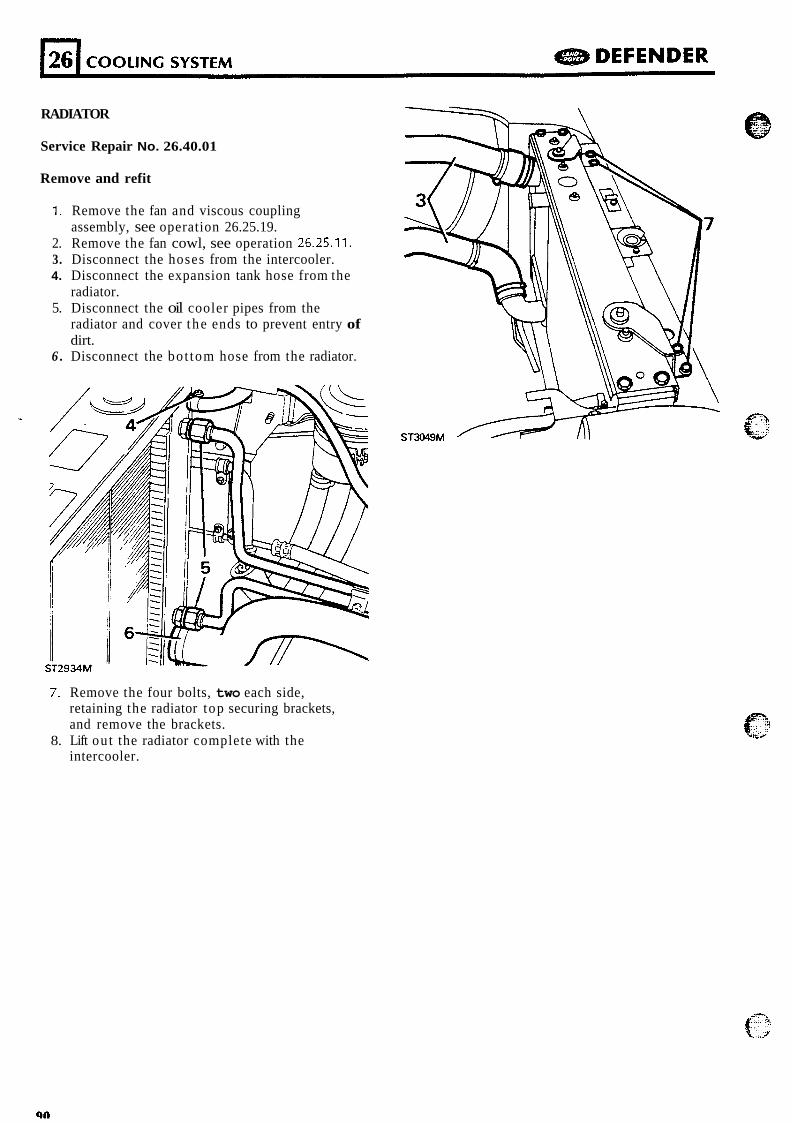
RADIATOR
Service Repair No. 26.40.01
Remove and refit
1. Remove the fan and viscous coupling assembly, see operation 26.25.19.
2. Remove the fan cowl, see operation 26.25.11. 3. Disconnect the hoses from the intercooler. 4. Disconnect the expansion tank hose from the
radiator. 5. Disconnect the oil cooler pipes from the
radiator and cover t he ends to prevent entry of dirt.
6 . Disconnect the bot tom hose from the radiator.
7. Remove the four bolts, two each side, retaining the radiator top securing brackets, and remove the brackets.
intercooler. 8. Lift ou t the radiator complete with the
4;--
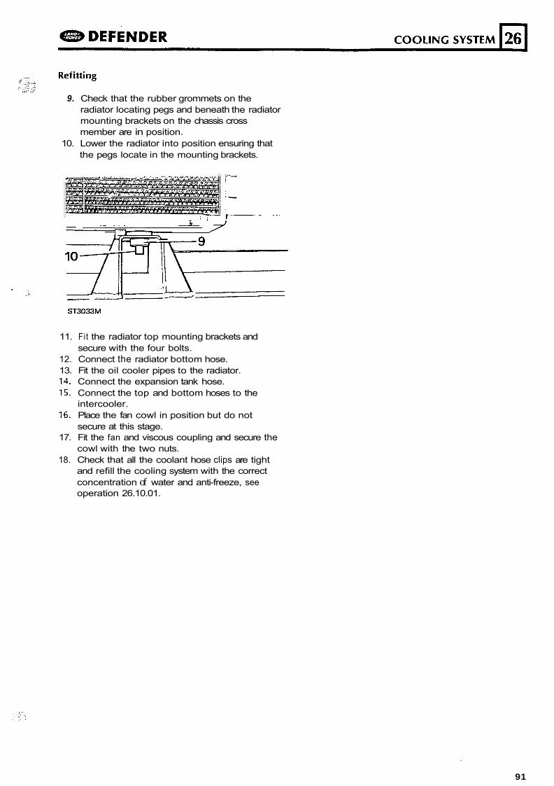
9. Check that the rubber grommets on the radiator locating pegs and beneath the radiator mounting brackets on the chassis cross member are in position.
10. Lower the radiator into position ensuring that the pegs locate in the mounting brackets.
lO----;-ii;LT
Z I - ST3033M
11. Fit the radiator top mounting brackets and secure with the four bolts.
12. Connect the radiator bottom hose. 13. Fit the oil cooler pipes to the radiator. 14. Connect the expansion tank hose. 15. Connect the top and bottom hoses to the
intercooler. 16. Place the fan cowl in position but do not
secure at this stage. 17. Fit the fan and viscous coupling and secure the
cowl with the two nuts. 18. Check that all the coolant hose clips are tight
and refill the cooling system with the correct concentration of water and anti-freeze, see operation 26.10.01.
91
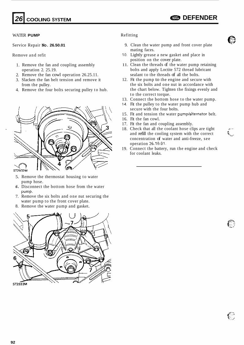
. 26
WATER PUMP
Service Repair No. 26.50.01
Remove a n d refit
DEFENDER COOLING SYSTEM
1.
2. 3.
4.
1
Remove the fan and coupling assembly operation 2. 25.19. Remove the fan cowl operation 26.25.11. Slacken the fan belt tension and remove it from the pulley. Remove the four bolts securing pulley t o hub.
5.
6 .
7.
8.
Remove the thermostat housing t o water pump hose. Disconnect the bottom hose from the water pump- Remove the six bolts and o n e nut securing the water pump t o the front cover plate. Remove the water pump and gasket.
Refitting
9.
10.
11.
12.
13. 14.
15. 16. 17. 18.
19.
Clean the water pump and front cover plate mating faces. Lightly grease a new gasket and place in position on the cover plate. Clean the threads of the water pump retaining bolts and apply Loctite 572 thread lubricant sealant t o the threads of all the bolts. Fit the pump to the engine and secure with the six bolts and one nut in accordance with the chart below. Tighten the fixings evenly and t o the correct torque. Connect the bottom hose t o the water pump. Fit the pulley t o the water pump hub and secure with the four bolts. Fit and tension the water pump/aiternator belt. Fit the fan cowl. Fit the fan and coupling assembly. Check that all the coolant hose clips are tight and refill the cooling system with the correct
r e
5 %. ., v
concentration of water and anti-freeze, s ee operation 26.10.01. Connect the battery, run the engine and check for coolant leaks.
92
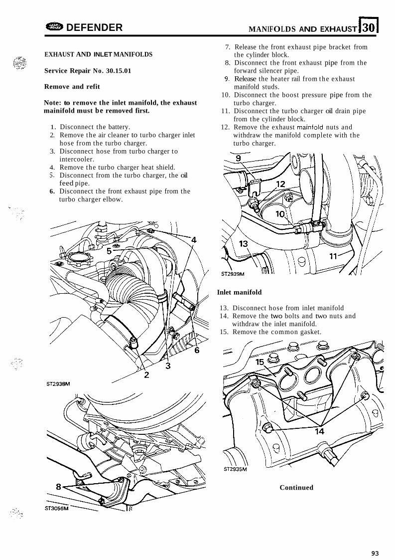
DEFENDER MANIFOLDS AND EXHAUST 130 I EXHAUST AND INLET MANIFOLDS
Service Repair No. 30.15.01
Remove and refit
Note: to remove the inlet manifold, the exhaust mainifold must be removed first.
1. Disconnect the battery. 2. Remove the air cleaner to turbo charger inlet
hose from the turbo charger. 3. Disconnect hose from turbo charger to
intercooler. 4. Remove the turbo charger heat shield. 5. Disconnect from the turbo charger, the oil
feed pipe. 6. Disconnect the front exhaust pipe from the
turbo charger elbow.
ST2938M
7. Release the front exhaust pipe bracket from the cylinder block.
8. Disconnect the front exhaust pipe from the forward silencer pipe.
9. Release the heater rail from the exhaust manifold studs.
10. Disconnect the boost pressure pipe from the turbo charger.
11. Disconnect the turbo charger oil drain pipe from the cylinder block.
12. Remove the exhaust mainfold nuts and withdraw the manifold complete with the turbo charger.
Inlet manifold
13. Disconnect hose from inlet manifold 14. Remove the two bolts and two nuts and
withdraw the inlet manifold. 15. Remove the common gasket.
Continued
93
301 MANIFOLDS AND EXHAUST DEFENDER
Ref ittng
15.
16.
17. 18.
19.
20.
- 21. 22.
23. 24. 25. 26. 27.
Place a new gasket in position and fit the inlet manifold and secure with the two bolts and two nuts and tighten t o the correct torque. Fit the exhaust manifold complete with turbo charger and secure with the nuts. Fit the heater rail to the manifold studs. Connect the turbo charger oil drain pipe to the cylinder block. Connect the boost pressure pipe t o the turbo charger. Using "HOLTS" "FIRE GUM" fit the front exhaust pipe t o the turbo charger elbow and secure with the clamp. Note, before fitting the pipe t o the elbow make sure that the securing clamp is above the inlet manifold since the clip will not pass between the front pipe and manifold. Connect the front pipe t o the forward silencer. Fit-the front pipe support bracket to the cylinder block with the single bolt. Connect the turbo charger oil feed pipe. Fit the intercooler t o turbo charger hose. Fit the air cleaner t o turbo charger hose. Fit the turbo charge heat shield. Connect the battery, run the engine and check for exhaust gas leaks.
94
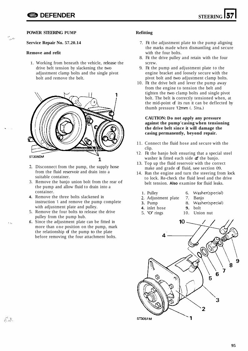
DEFENDER STEERING n 57
POWER STEERING PUMP
Service Repair No. 57.20.14 , 2 -
"- ".
Remove and refit
1. Working from beneath the vehicle, release the drive belt tension by slackening the two adjustment clamp bolts and the single pivot bolt and remove the belt.
ST3050M \y
1 2. Disconnect from the pump, the supply hose
from the fluid reservoir and drain into a suitable container.
3. Remove the banjo union bolt from the rear of the pump and allow fluid to drain into a container.
4. Remove the three bolts slackened in instruction 1 and remove the pump complete with adjustment plate and pulley.
5. Remove the four bolts to release the drive pulley from the pump hub.
6 . Since the adjustment plate can be fitted in more than one position on the pump, mark the relationship of the pump to the plate before removing the four attachment bolts.
' .
Refitting
7. Fit the adjustment plate to the pump aligning the marks made when dismantling and secure with the four bolts.
screw.
engine bracket and loosely secure with the pivot bolt and two adjustment clamp bolts.
10. Fit the drive belt and lever the pump away from the engine t o tension the belt and tighten the two clamp bolts and single pivot bolt. The belt is correctly tensioned when, at the mid-point of its run it can be deflected by thumb pressure 12" (. 5ins.)
8. Fit the drive pulley and retain with the four
9. Fit the pump and adjustment plate t o the
CAUTION: Do not apply any pressure against the pump'casing when tensioning the drive belt since it will damage the casing permanently, beyond repair.
11. Connect the fluid hose and secure with the clip.
12. Fit the banjo bolt ensuring that a special steel washer is fitted each side of the banjo.
13. Top up the fluid reservoir with the correct make and grade of fluid, see section 09.
14. Run the engine and turn the steering from lock t o lock. Re-check the fluid level and the drive belt tension. Also examine for fluid leaks.
1. Pulley 6. Washer(specia1) 2. Adjustment plate 7. Banjo 3. Pump 8. Washer(specia1) 4. inlet hose 9. bolt 5. '0' rings 10. Union nut
ST3051 M '1
95

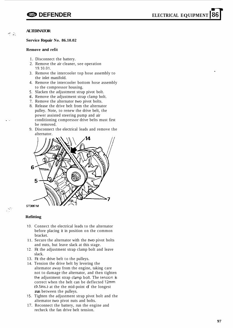
n 42$B DEFENDER ELECTRICAL EQUIPMENT I86 I ALTERNATOR
Service Repair No. 86.10.02
24% 4. ,:\ . .
Remove and refit
1. Disconnect the battery. 2. Remove the air cleaner, see operation
19.10.01. 3. Remove the intercooler top hose assembly t o
the inlet manifold. 4. Remove the intercooler bottom hose assembly
to the compressor housing. 5. Slacken the adjustment strap pivot bolt. 6 . Remove the adjustment strap clamp bolt. 7. Remove the alternator two pivot bolts. 8. Release the drive belt from the alternator
pulley. Note, to renew the drive belt, the power assisted steering pump and air conditioning compressor drive belts must first be removed.
9. Disconnect the electrical leads and remove the alternator.
Refitting
10. Connect the electrical leads to the alternator before placing it in position on the common bracket.
11. Secure the alternator with the two pivot bolts and nuts, but leave slack at this stage.
12. Fit the adjustment strap clamp bolt and leave slack.
13. Fit the drive belt t o the pulleys. 14. Tension the drive belt by levering the
altemator away from the engine, taking care not t o damage the alternator, and then tighten the adjustment strap c!amp bok. The tensicn is correct when the belt can be deflected 12mm (0.5ins.I at the the mid-point of the longest run between the pulleys.
15. Tighten the adjustment strap pivot bolt and the altemator two pivot nuts and bolts.
17. Reconnect the battery, run the engine and recheck the fan drive belt tension.
97

"