deepwater applications of mpd iadc ubo/mpd · pdf filedeepwater applications of mpd ... made...
TRANSCRIPT

Copyright © 2014IADC Drilling Manual
Deepwater applications of MPDCBHP and PMCD have been safely and effectively practiced globally on prospects deemed un-drillable with convention-al means for safety, economic or technical reasons. This is understandable when considering that new technology is most often applied only when conventional wisdom fails. RFC-HSE is just beginning to be seen as maybe a better way to drill some prospects that could be drilled conventionally. Although there have been hundreds of riserless DGD appli-cations, DGD with a marine riser and subsea BOP is still in its infancy.
On floating rigs such as moored semisubmersibles and dy-namically positioned drill ships, the kit required to practice CBHP, PMCD and RFC-HSE variations has evolved to include several offshore RCD configurations, PLC automated choke manifold systems for early kick-loss detection, real-time determination of actual drilling windows, ability to conduct frequent dynamic FITs and quantify ballooning phenomenon upon each jointed pipe connection.
The RCD should be tested and rated by the provider in ac-cordance with API 16RCD. Deepwater designs include those suitable for being configured on top of a collapsed upper marine riser slip joint, above the marine riser tension ring and below the slip joint, below the marine riser tension ring, and anywhere within the marine riser itself above the subsea BOP. The bodies of the RCD designs to be configured below the riser tension ring to serve as a marine riser spool section and therefore must have suitable tensile strength, typically 3,000,000 lb.
Another marine design is the “Docking Station RCD”, Figure MP-6, whose body is configured above the tension ring and below the rig’s telescoping slip joint. In this configuration, the slip joint above requires an inside diameter that permits deployment and retrieval of the RCD’s bearing and annular seal assembly. Each design requires a dedicated running tool for deploying the RCD’s bearing and seal assembly, fa-cilitating transition from conventional drilling to MPD and vice versa.
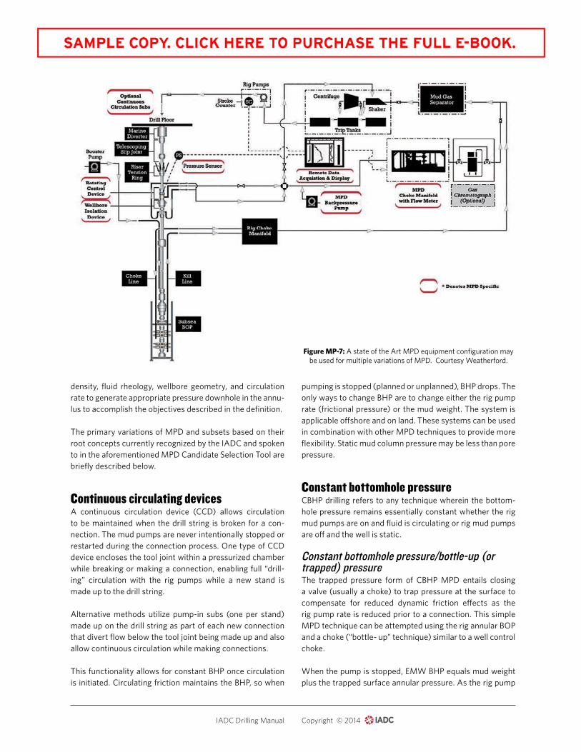
Figure MP-7 is a schematic that may be considered a state-or-the-art equipment configuration for the practice of CBHP, PMCD and RFC-HSE variations. In this case, the RCD is con-figured below the marine riser tension ring, a location that does not require modifications to the rig’s existing upper marine riser system, as well as enabling significant headings changes on drill ships. The ease at which the RCD’s bearing and annular seal assembly may be deployed and retrieved facilitates relatively rapid transition from conventional drill-ing to MPD and vice versa.
IADC UBO/MPD Committee technical support The IADC UBO/MPD Committee has been active in devel-oping recommended practices and HSE Guidelines for both MPD and UBD. Subject matter experts on the committee have strived to aid the industry in safe and effective practice of both drilling methods, and those interested in practicing UBO or MPD are encouraged to access the results of their collective thinking via IADC’s website.
Key enabling equipment One enabling tool that is most common to the drilling meth-ods discussed in this chapter is the RCD. The availability of RCD designs applicable to enable drilling on any type of land and offshore rig with closed and circulating fluids that can be pressurized have played key role in the evolution and wide acceptance of the drilling techniques discussed in this chapter. Methods of applying surface back pressure may also require the use of drill string non-return valves or floats. Choke systems may be manually operated semi-automat-ic or PLC automatic. UBD and MPD can be safely practiced with a manual or semi-automatic manifold system. Howev-er, applications of MPD on challenging onshore wells and most offshore wells have prompted the development of PLC automatic choke control systems.
Other key enabling equipment to practice the drilling meth-ods discussed in this chapter that is likely to be in addition to the rig’s regular equipment includes downhole deployment valves, mud /gas separators of sufficient capacity, nitrogen production units, pitless air drilling systems, air compres-sion, mass-flow meters, gas chromatographs, continuous circulating systems, and systems to make and break foams.
Such specialized equipment is most often provided by ser-vice providers and often rented or leased by the operator or rig contractor. When air/gas/mist/foam drilling, UBD or MPD are practiced on their rig, regular rig personnel should familiarize themselves with the required specialized equip-ment and receive training from the provider if asked to assist in its safe operation and/or maintenance.
Managed pressure drilling As mentioned in the introduction to this chapter, MPD is de-fined as “an adaptive drilling process used to precisely con-trol the annular pressure profile throughout the wellbore. The objectives are to ascertain the downhole pressure en-vironment limits and to manage the annular hydraulic pres-sure profile accordingly. It is the intention of MPD to avoid continuous influx of formation fluids to the surface. Any in-flux incidental to the operation will be safely contained using an appropriate process.”
MANAGED PRESSURE MP–5

Copyright © 2014IADC Drilling Manual
MPD includes the four variations briefly described in the introduction. They and subsets based upon their root prin-ciples have been described by the IADC in their MPD Selec-tion Tool. Go to http://mpdtool.iadc.org/ to register and use the tool. Or scan the QR Code.
These different variations and techniques precisely control annular pressure using combinations of applied pressure (usually at the surface), hydrostatic head and dynamic fric-tion. These three elements of annular pressure are in turn affected by altering the combination of back pressure, fluid
MP–6 MANAGED PRESSURE
Figure MP-6: Marine Series RCD whose body is an integral component of the marine riser system. Courtesy Weatherford.
density, fluid rheology, wellbore geometry, and circulation rate to generate appropriate pressure downhole in the annu-lus to accomplish the objectives described in the definition.
The primary variations of MPD and subsets based on their root concepts currently recognized by the IADC and spoken to in the aforementioned MPD Candidate Selection Tool are briefly described below.
Continuous circulating devices A continuous circulation device (CCD) allows circulation to be maintained when the drill string is broken for a con-nection. The mud pumps are never intentionally stopped or restarted during the connection process. One type of CCD device encloses the tool joint within a pressurized chamber while breaking or making a connection, enabling full “drill-ing” circulation with the rig pumps while a new stand is made up to the drill string.
Alternative methods utilize pump-in subs (one per stand) made up on the drill string as part of each new connection that divert flow below the tool joint being made up and also allow continuous circulation while making connections.
This functionality allows for constant BHP once circulation is initiated. Circulating friction maintains the BHP, so when
pumping is stopped (planned or unplanned), BHP drops. The only ways to change BHP are to change either the rig pump rate (frictional pressure) or the mud weight. The system is applicable offshore and on land. These systems can be used in combination with other MPD techniques to provide more flexibility. Static mud column pressure may be less than pore pressure.
Constant bottomhole pressure CBHP drilling refers to any technique wherein the bottom-hole pressure remains essentially constant whether the rig mud pumps are on and fluid is circulating or rig mud pumps are off and the well is static.
Constant bottomhole pressure/bottle-up (or trapped) pressureThe trapped pressure form of CBHP MPD entails closing a valve (usually a choke) to trap pressure at the surface to compensate for reduced dynamic friction effects as the rig pump rate is reduced prior to a connection. This simple MPD technique can be attempted using the rig annular BOP and a choke (“bottle- up” technique) similar to a well control choke.
When the pump is stopped, EMW BHP equals mud weight plus the trapped surface annular pressure. As the rig pump
MANAGED PRESSURE MP–7
Figure MP-7: A state of the Art MPD equipment configuration may be used for multiple variations of MPD. Courtesy Weatherford.
Copyright © 2014IADC Drilling Manual