deep sea 7420
TRANSCRIPT

7/14/2019 DEEP SEA 7420
http://slidepdf.com/reader/full/deep-sea-7420-56327e12a4616 1/114
DSE7400 Operator Manual ISSUE 1
DEEP SEA ELECTRONICS PLCDSE7400 Operator Manual
Document Number 057-161
Author: Ashley Senior
7/14/2019 DEEP SEA 7420
http://slidepdf.com/reader/full/deep-sea-7420-56327e12a4616 2/114
DSE7400 Operator Manual
2
DEEP SEA ELECTRONICS PLC
Highfield HouseHunmanbyNorth Yorkshire
YO14 0PHENGLAND
Sales Tel: +44 (0) 1723 890099Sales Fax: +44 (0) 1723 893303
E-mail : [email protected] : www.deepseaplc.com
DSE7400 Operator Manual
© Deep Sea Electronics Plc
All rights reserved. No part of this publication may be reproduced in any material form (includingphotocopying or storing in any medium by electronic means or other) without the written permission ofthe copyright holder except in accordance with the provisions of the Copyright, Designs and PatentsAct 1988.Applications for the copyright holder’s written permission to reproduce any part of this publicationshould be addressed to Deep Sea Electronics Plc at the address above.
The DSE logo is a UK registered trademarks of Deep Sea Electronics PLC.
Any reference to trademarked product names used within this publication is owned by their respectivecompanies.
Deep Sea Electronics Plc reserves the right to change the contents of this document without prior
notice.
Amendments List
Issue Comments MinimumModuleversionrequired
MinimumConfiguration Suite
Version required
1 Initial release V1.0.0 2011.10v1.0.7
Typeface: The typeface used in this document is Arial . Care should be taken not to mistake the upper case letter I with the numeral 1. The numeral1 has a top serif to avoid this confusion.
Clarification of notation used within this publication.
NOTE:Highlights an essential element of a procedure to ensure correctness.
CAUTION!Indicates a procedure or practice, which, if not strictly observed, could result indamage or destruction of equipment.
WARNING!Indicates a procedure or practice, which could result in injury to personnel or lossof life if not followed correctly.
7/14/2019 DEEP SEA 7420
http://slidepdf.com/reader/full/deep-sea-7420-56327e12a4616 3/114
DSE7400 Operator Manual
3
TABLE OF CONTENTS
Section Page
1 BIBLIOGRAPHY .............................................................................................. 7 1.1 INSTALLATION INSTRUCTIONS ....................................................................................... 7 1.2 TRAINING GUIDES ............................................................................................................. 7 1.3 MANUALS ........................................................................................................................... 7 1.4 THIRD PARTY DOCUMENTS ............................................................................................. 7
2 INTRODUCTION .............................................................................................. 8 3 SPECIFICATIONS ............................................................................................ 9
3.1 PART NUMBERING ............................................................................................................ 9 3.1.1 SHORT NAMES ............................................................................................................ 9
3.2 TERMINAL SPECIFICATION ............................................................................................ 10 3.3 POWER SUPPLY REQUIREMENTS ................................................................................ 10 3.4 GENERATOR VOLTAGE / FREQUENCY SENSING ....................................................... 10 3.5 GENERATOR CURRENT SENSING ................................................................................ 11 3.5.1 VA RATING OF THE CTS .......................................................................................... 11
3.5.2 CT POLARITY ............................................................................................................ 12 3.5.3 CT PHASING .............................................................................................................. 12 3.5.4 CT CLASS .................................................................................................................. 12
3.6 INPUTS .............................................................................................................................. 13 3.6.1 DIGITAL INPUTS ........................................................................................................ 13 3.6.2 ANALOGUE INPUTS .................................................................................................. 13
3.6.2.1 OIL PRESSURE .................................................................................................. 13 3.6.2.2 COOLANT TEMPERATURE ............................................................................... 13 3.6.2.3 FUEL LEVEL ....................................................................................................... 13 3.6.2.4 FLEXIBLE SENSOR ............................................................................................ 14
3.6.3 CHARGE FAIL INPUT ................................................................................................ 14 3.6.4 MAGNETIC PICKUP ................................................................................................... 14 3.7 OUTPUTS .......................................................................................................................... 15 3.7.1 OUTPUTS A & B ......................................................................................................... 15 3.7.2 CONFIGURABLE OUTPUTS C & D (LOAD SWITCHING) ....................................... 15
3.7.2.1 CONTACTOR COILS .......................................................................................... 15 3.7.2.2 UNDERVOLTAGE (UV COILS) ........................................................................... 15 3.7.2.3 CLOSING COILS ................................................................................................. 16 3.7.2.4 OPENING COILS / SHUNT TRIP COILS ............................................................ 16
3.7.3 OUTPUTS E,F,G,H, I & J ........................................................................................... 16 3.8 COMMUNICATION PORTS .............................................................................................. 17 3.9 COMMUNICATION PORT USAGE .................................................................................. 17
3.9.1 CAN INTERFACE ...................................................................................................... 17 3.9.2 USB CONNECTION ................................................................................................... 18 3.9.3 USB HOST-MASTER (USB DRIVE CONNECTION) ................................................. 18 3.9.4 RS232 ......................................................................................................................... 19
3.9.4.1 RECOMMENDED PC RS232 SERIAL PORT ADD-ONS ................................... 19 3.9.4.2 RECOMMENDED EXTERNAL MODEMS: ......................................................... 20
3.9.5 RS485 ......................................................................................................................... 21 3.9.5.1 RECOMMENDED PC RS485 SERIAL PORT ADD-ONS ................................... 21
3.9.6 ETHERNET ................................................................................................................. 22 3.9.6.1 DIRECT PC CONNECTION ................................................................................ 22 3.9.6.2 CONNECTION TO BASIC ETHERNET .............................................................. 23 3.9.6.3 CONNECTION TO COMPANY INFRASTRUCTURE ETHERNET..................... 24 3.9.6.4 CONNECTION TO THE INTERNET ................................................................... 25 3.9.6.5 FIREWALL CONFIGURATION FOR INTERNET ACCESS ................................ 27
3.10 DSENET® FOR EXPANSION MODULES.................................................................... 28 3.10.1 DSENET® USED FOR MODBUS ENGINE CONNECTION ...................................... 28 3.11 SOUNDER ...................................................................................................................... 29
7/14/2019 DEEP SEA 7420
http://slidepdf.com/reader/full/deep-sea-7420-56327e12a4616 4/114
DSE7400 Operator Manual
4
3.11.1 ADDING AN EXTERNAL SOUNDER TO THE APPLICATION .................................. 29 3.12 ACCUMULATED INSTRUMENTATION ........................................................................ 29 3.13 DIMENSIONS AND MOUNTING ................................................................................... 30
3.13.1 DIMENSIONS ............................................................................................................. 30 3.13.2 PANEL CUTOUT ........................................................................................................ 30 3.13.3 WEIGHT ..................................................................................................................... 30 3.13.4 FIXING CLIPS ............................................................................................................. 31 3.13.5 CABLE TIE FIXING POINTS ...................................................................................... 32 3.13.6 SILICON SEALING GASKET ..................................................................................... 32
3.14 APPLICABLE STANDARDS ......................................................................................... 33 3.14.1 ENCLOSURE CLASSIFICATIONS ............................................................................. 35 3.14.2 NEMA CLASSIFICATIONS ......................................................................................... 36
4 INSTALLATION ............................................................................................. 37 4.1 TERMINAL DESCRIPTION ............................................................................................... 37
4.1.1 DC SUPPLY, FUEL AND START OUTPUTS, OUTPUTS E-J ................................... 38 4.1.2 ANALOGUE SENSOR ................................................................................................ 39 4.1.3 MAGNETIC PICKUP, CAN AND EXPANSION .......................................................... 40 4.1.4 LOAD SWITCHING AND V1 GENERATOR VOLTAGE SENSING ........................... 41 4.1.5
V2 BUS/MAINS VOLTAGE SENSING ........................................................................ 41
4.1.6 GENERATOR CURRENT TRANSFORMERS ........................................................... 42 4.1.7 CONFIGURABLE DIGITAL INPUTS .......................................................................... 44 4.1.8 PC CONFIGURATION INTERFACE CONNECTOR .................................................. 44 4.1.9 RS485 CONNECTOR ................................................................................................. 45 4.1.10 RS232 CONNECTOR ................................................................................................. 45
4.2 TYPICAL WIRING DIAGRAMS ......................................................................................... 46 4.2.1 DSE7410 3 PHASE, 4 WIRE WITH RESTRICTED EARTH FAULT PROTECTION . 47 4.2.2 DSE7420 3 PHASE, 4 WIRE WITH RESTRICTED EARTH FAULT PROTECTION . 48
4.3 ALTERNATIVE TOPOLOGIES ......................................................................................... 49 4.3.1 3 PHASE, 4 WIRE WITHOUT EARTH FAULT PROTECTION .................................. 49 4.3.2 SINGLE PHASE WITH RESTRICTED EARTH FAULT ............................................. 50 4.3.3 SINGLE PHASE WITHOUT EARTH FAULT .............................................................. 50 4.3.4 2 PHASE (L1 & L2) 3 WIRE WITH RESTRICTED EARTH FAULT ........................... 51 4.3.5 2 PHASE (L1 & L2) 3 WIRE WITHOUT EARTH FAULT ............................................ 51 4.3.6 2 PHASE (L1 & L3) 3 WIRE WITH RESTRICTED EARTH FAULT ........................... 52 4.3.7 2 PHASE (L1 & L3) 3 WIRE WITHOUT EARTH FAULT MEASURING ..................... 52 4.3.8 3 PHASE 4 WIRE WITH UNRESTRICTED EARTH FAULT MEASURING ............... 53
4.4 EARTH SYSTEMS ............................................................................................................. 54 4.4.1 NEGATIVE EARTH ..................................................................................................... 54 4.4.2 POSITIVE EARTH ...................................................................................................... 54 4.4.3 FLOATING EARTH ..................................................................................................... 54
4.5 TYPICAL ARRANGEMENT OF DSENET® ...................................................................... 54 5 DESCRIPTION OF CONTROLS .................................................................... 55
5.1 DSE7410 AUTO START CONTROL MODULE ................................................................ 55 5.2
DSE7420 AUTO START CONTROL MODULE ................................................................ 56
5.3 QUICKSTART GUIDE ....................................................................................................... 57
5.3.1 STARTING THE ENGINE ........................................................................................... 57 5.3.2 STOPPING THE ENGINE .......................................................................................... 57
5.4 VIEWING THE INSTRUMENT PAGES ............................................................................. 58 5.4.1 STATUS ...................................................................................................................... 59 5.4.2 ENGINE ...................................................................................................................... 60 5.4.3 GENERATOR ............................................................................................................. 61 5.4.4 BUS (DSE7410 ONLY) ............................................................................................... 62 5.4.5 MAINS (DSE7420 ONLY) ........................................................................................... 62 5.4.6 RS232 SERIAL PORT ................................................................................................ 62 5.4.7 RS485 SERIAL PORT ................................................................................................ 65 5.4.8 ABOUT ........................................................................................................................ 66
5.4.8.1 ETHERNET PAGES ............................................................................................ 67 5.4.8.2 DATA LOGGING PAGES .................................................................................... 68 5.4.9 CAN ERROR MESSAGES ......................................................................................... 69
7/14/2019 DEEP SEA 7420
http://slidepdf.com/reader/full/deep-sea-7420-56327e12a4616 5/114
DSE7400 Operator Manual
5
5.5 VIEWING THE EVENT LOG.............................................................................................. 70 5.6 USER CONFIGURABLE INDICATORS ............................................................................ 71
6 OPERATION .................................................................................................. 72 6.1 CONTROL ......................................................................................................................... 72 6.2 CONTROL PUSH-BUTTONS ............................................................................................ 73 6.3 ALTERNATIVE CONFIGURATIONS ................................................................................ 74 6.4 DUMMY LOAD / LOAD SHEDDING CONTROL .............................................................. 75 6.5 STOP MODE ...................................................................................................................... 76
6.5.1 ECU OVERRIDE ......................................................................................................... 77 6.6 MANUAL MODE ................................................................................................................ 78
6.6.1 WAITING IN MANUAL MODE .................................................................................... 78 6.6.2 STARTING SEQUENCE............................................................................................. 78 6.6.3 ENGINE RUNNING .................................................................................................... 79 6.6.4 MANUAL FUEL PUMP CONTROL ............................................................................. 79 6.6.5 MANUAL SPEED CONTROL ..................................................................................... 79 6.6.6 STOPPING SEQUENCE ............................................................................................ 80
6.7 TEST MODE ...................................................................................................................... 80 6.7.1 WAITING IN TEST MODE .......................................................................................... 80 6.7.2 STARTING SEQUENCE............................................................................................. 80 6.7.3 ENGINE RUNNING .................................................................................................... 81
6.8 AUTOMATIC MODE .......................................................................................................... 82 6.8.1 WAITING IN AUTO MODE ......................................................................................... 82 6.8.2 STARTING SEQUENCE............................................................................................. 82 6.8.3 ENGINE RUNNING .................................................................................................... 83 6.8.4 STOPPING SEQUENCE ............................................................................................ 83
7 PROTECTIONS .............................................................................................. 84 7.1 PROTECTIONS DISABLED .............................................................................................. 85
7.1.1 INDICATION / WARNING ALARMS ........................................................................... 85 7.1.2 SHUTDOWN / ELECTRICAL TRIP ALARMS ............................................................ 85 7.1.3 CAN ALARMS ............................................................................................................. 86
7.2 INDICATIONS .................................................................................................................... 87 7.3 WARNINGS ....................................................................................................................... 88 7.4 HIGH CURRENT WARNING ALARM ............................................................................... 89 7.5 SHUTDOWNS .................................................................................................................... 90 7.6 ELECTRICAL TRIPS ......................................................................................................... 92 7.7 HIGH CURRENT SHUTDOWN / ELECTRICAL TRIP ALARM ........................................ 93
7.7.1 IMMEDIATE WARNING ............................................................................................. 93 7.7.2 IDMT ALARM .............................................................................................................. 93
7.8 EARTH FAULT SHUTDOWN / ELECTRICAL TRIP ALARM ........................................... 96 7.9 SHORT CIRCUIT ALARM ................................................................................................. 97 7.10 MAINTENANCE ALARM ............................................................................................... 98
8 SCHEDULER ................................................................................................. 99 8.1.1 STOP MODE .............................................................................................................. 99 8.1.2 MANUAL MODE ......................................................................................................... 99 8.1.3 AUTO MODE .............................................................................................................. 99
9 FRONT PANEL CONFIGURATION ............................................................. 100 9.1 ACCESSING THE MAIN FRONT PANEL CONFIGURATION EDITOR ......................... 101
9.1.1 EDITING A PARAMETER ......................................................................................... 102 9.2 ADJUSTABLE PARAMETERS ....................................................................................... 103 9.3 ACCESSING THE ‘RUNNING’ CONFIGURATION EDITOR .......................................... 104
9.3.1 EDITING A PARAMETER ......................................................................................... 104 9.3.2 ADJUSTABLE PARAMETERS (RUNNING EDITOR) .............................................. 104
10 COMMISSIONING ..................................................................................... 105 10.1 PRE-COMMISSIONING ............................................................................................... 105
11 FAULT FINDING ....................................................................................... 106
7/14/2019 DEEP SEA 7420
http://slidepdf.com/reader/full/deep-sea-7420-56327e12a4616 6/114
DSE7400 Operator Manual
6
11.1 STARTING ................................................................................................................... 106 11.2 LOADING ..................................................................................................................... 106 11.3 ALARMS ...................................................................................................................... 107 11.4 COMMUNICATIONS .................................................................................................... 108 11.5 INSTRUMENTS ........................................................................................................... 109 11.6 MISCELLANEOUS ...................................................................................................... 109
12 MAINTENANCE, SPARES, REPAIR AND SERVICING ........................... 110 12.1 PURCHASING ADDITIONAL CONNECTOR PLUGS FROM DSE ............................. 110
12.1.1 PACK OF PLUGS ..................................................................................................... 110 12.1.2 INDIVIDUAL PLUGS ................................................................................................. 110
12.2 PURCHASING ADDITIONAL FIXING CLIPS FROM DSE .......................................... 110 12.3 PURCHASING ADDITIONAL SEALING GASKET FROM DSE ................................. 110 12.4 DSENET EXPANSION MODULES .............................................................................. 111
13 WARRANTY .............................................................................................. 112 14 DISPOSAL ................................................................................................ 112
14.1 WEEE (WASTE ELECTRICAL AND ELECTRONIC EQUIPMENT) ........................... 112 14.2
ROHS (RESTRICTION OF HAZARDOUS SUBSTANCES) ........................................ 112
7/14/2019 DEEP SEA 7420
http://slidepdf.com/reader/full/deep-sea-7420-56327e12a4616 7/114
Bibliography
7
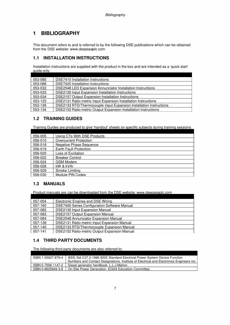
1 BIBLIOGRAPHY
This document refers to and is referred to by the following DSE publications which can be obtainedfrom the DSE website: www.deepseaplc.com
1.1 INSTALLATION INSTRUCTIONS
Installation instructions are supplied with the product in the box and are intended as a ‘quick start’guide only.
DSE PART DESCRIPTION053-085 DSE7410 Installation Instructions053-088 DSE7420 Installation Instructions053-032 DSE2548 LED Expansion Annunciator Installation Instructions053-033 DSE2130 Input Expansion Installation Instructions053-034 DSE2157 Output Expansion Installation Instructions053-125 DSE2131 Ratio-metric Input Expansion Installation Instructions053-126 DSE2133 RTD/Thermocouple Input Expansion Installation Instructions053-134 DSE2152 Ratio-metric Output Expansion Installation Instructions
1.2 TRAINING GUIDES
Training Guides are produced to give ‘handout’ sheets on specific subjects during training sessions
DSE PART DESCRIPTION056-005 Using CTs With DSE Products056-010 Overcurrent Protection056-018 Negative Phase Sequence056-019 Earth Fault Protection056-020 Loss of Excitation056-022 Breaker Control
056-024 GSM Modem056-026 kW & kVAr056-029 Smoke Limiting056-030 Module PIN Codes
1.3 MANUALS
Product manuals are can be downloaded from the DSE website: www.deepseaplc.com
DSE PART DESCRIPTION057-004 Electronic Engines and DSE Wiring057-160 DSE7400 Series Configuration Software Manual057-082 DSE2130 Input Expansion Manual
057-083 DSE2157 Output Expansion Manual057-084 DSE2548 Annunciator Expansion Manual057-139 DSE2131 Ratio-metric Input Expansion Manual057-140 DSE2133 RTD/Thermocouple Expansion Manual057-141 DSE2152 Ratio-metric Output Expansion Manual
1.4 THIRD PARTY DOCUMENTS
The following third party documents are also referred to:
REFERENCE DESCRIPTIONISBN 1-55937-879-4 IEEE Std C37.2-1996 IEEE Standard Electrical Power System Device Function
Numbers and Contact Designations. Institute of Electrical and Electronics Engineers Inc ISBN 0-7506-1147-2 Diesel generator handbook. L.L.J.Mahon
ISBN 0-9625949-3-8 On-Site Power Generation. EGSA Education Committee.
7/14/2019 DEEP SEA 7420
http://slidepdf.com/reader/full/deep-sea-7420-56327e12a4616 8/114
Introduction
8
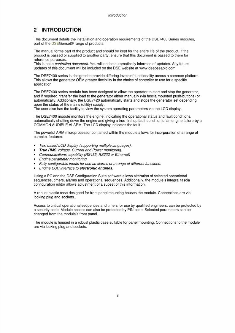
2 INTRODUCTION
This document details the installation and operation requirements of the DSE7400 Series modules,part of the DSEGenset® range of products.
The manual forms part of the product and should be kept for the entire life of the product. If the
product is passed or supplied to another party, ensure that this document is passed to them forreference purposes.This is not a controlled document. You will not be automatically informed of updates. Any futureupdates of this document will be included on the DSE website at www.deepseaplc.com
The DSE7400 series is designed to provide differing levels of functionality across a common platform.This allows the generator OEM greater flexibility in the choice of controller to use for a specificapplication.
The DSE7400 series module has been designed to allow the operator to start and stop the generator,and if required, transfer the load to the generator either manually (via fascia mounted push-buttons) orautomatically. Additionally, the DSE7420 automatically starts and stops the generator set dependingupon the status of the mains (utility) supply.
The user also has the facility to view the system operating parameters via the LCD display.
The DSE7400 module monitors the engine, indicating the operational status and fault conditions,automatically shutting down the engine and giving a true first up fault condition of an engine failure by aCOMMON AUDIBLE ALARM. The LCD display indicates the fault.
The powerful ARM microprocessor contained within the module allows for incorporation of a range ofcomplex features:
• Text based LCD display (supporting multiple languages).
• True RMS Voltage, Current and Power monitoring.
• Communications capability (RS485, RS232 or Ethernet)
• Engine parameter monitoring.
• Fully configurable inputs for use as alarms or a range of different functions.• Engine ECU interface to electronic engines .
Using a PC and the DSE Configuration Suite software allows alteration of selected operationalsequences, timers, alarms and operational sequences. Additionally, the module’s integral fasciaconfiguration editor allows adjustment of a subset of this information.
A robust plastic case designed for front panel mounting houses the module. Connections are vialocking plug and sockets..
Access to critical operational sequences and timers for use by qualified engineers, can be protected bya security code. Module access can also be protected by PIN code. Selected parameters can bechanged from the module’s front panel.
The module is housed in a robust plastic case suitable for panel mounting. Connections to the moduleare via locking plug and sockets.
7/14/2019 DEEP SEA 7420
http://slidepdf.com/reader/full/deep-sea-7420-56327e12a4616 9/114
Specification
9
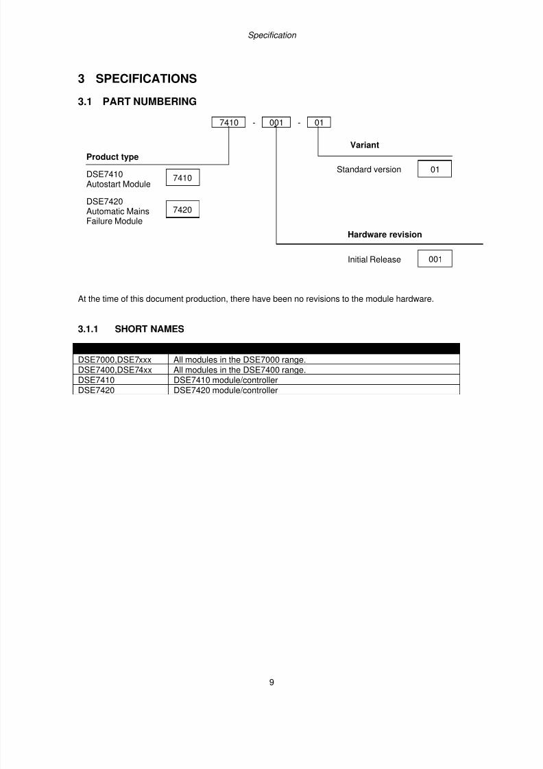
3 SPECIFICATIONS
3.1 PART NUMBERING
7410 - 001 - 01
At the time of this document production, there have been no revisions to the module hardware.
3.1.1 SHORT NAMES
Short name DescriptionDSE7000,DSE7xxx All modules in the DSE7000 range.DSE7400,DSE74xx All modules in the DSE7400 range.
DSE7410 DSE7410 module/controllerDSE7420 DSE7420 module/controller
Product type
DSE7410Autostart Module
7410
Variant
Standard version 01
Hardware revision
Initial Release 001
DSE7420Automatic MainsFailure Module
7420
7/14/2019 DEEP SEA 7420
http://slidepdf.com/reader/full/deep-sea-7420-56327e12a4616 10/114
Specification
10
3.2 TERMINAL SPECIFICATION
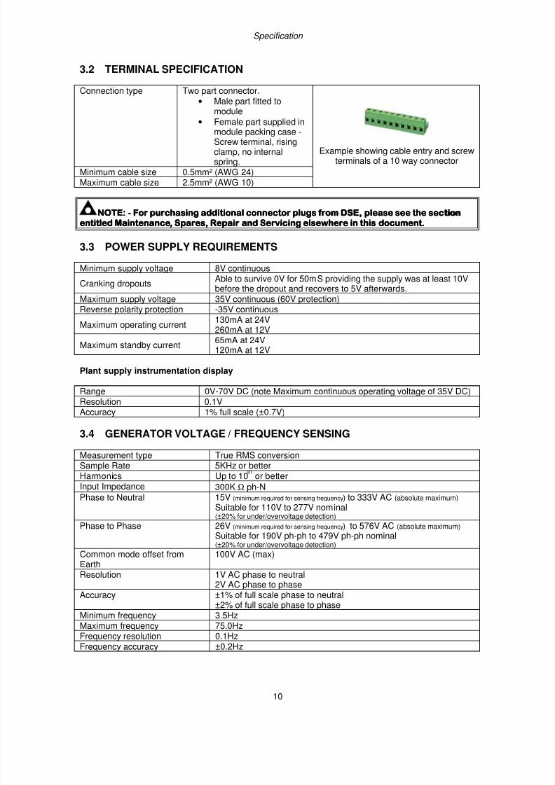
Connection type Two part connector.
• Male part fitted tomodule
• Female part supplied in
module packing case -Screw terminal, risingclamp, no internalspring.
Example showing cable entry and screwterminals of a 10 way connector
Minimum cable size 0.5mm² (AWG 24)Maximum cable size 2.5mm² (AWG 10)
NOTE:NOTE:NOTE:NOTE: ---- For purchasing additional connector plugs from DSE, please see the secFor purchasing additional connector plugs from DSE, please see the secFor purchasing additional connector plugs from DSE, please see the secFor purchasing additional connector plugs from DSE, please see the sectiontiontiontionentitled Maintenance, Spares, Repair and Servicing elsewhere in this document.entitled Maintenance, Spares, Repair and Servicing elsewhere in this document.entitled Maintenance, Spares, Repair and Servicing elsewhere in this document.entitled Maintenance, Spares, Repair and Servicing elsewhere in this document.
3.3 POWER SUPPLY REQUIREMENTS
Minimum supply voltage 8V continuous
Cranking dropoutsAble to survive 0V for 50mS providing the supply was at least 10Vbefore the dropout and recovers to 5V afterwards.
Maximum supply voltage 35V continuous (60V protection)Reverse polarity protection -35V continuous
Maximum operating current130mA at 24V260mA at 12V
Maximum standby current65mA at 24V120mA at 12V
Plant supply instrumentation display
Range 0V-70V DC (note Maximum continuous operating voltage of 35V DC)Resolution 0.1VAccuracy 1% full scale (±0.7V)
3.4 GENERATOR VOLTAGE / FREQUENCY SENSING
Measurement type True RMS conversionSample Rate 5KHz or betterHarmonics Up to 10 or betterInput Impedance 300K Ω ph-NPhase to Neutral 15V (minimum required for sensing frequency) to 333V AC (absolute maximum)
Suitable for 110V to 277V nominal
(±20% for under/overvoltage detection) Phase to Phase 26V (minimum required for sensing frequency) to 576V AC (absolute maximum)
Suitable for 190V ph-ph to 479V ph-ph nominal(±20% for under/overvoltage detection)
Common mode offset fromEarth
100V AC (max)
Resolution 1V AC phase to neutral2V AC phase to phase
Accuracy ±1% of full scale phase to neutral±2% of full scale phase to phase
Minimum frequency 3.5HzMaximum frequency 75.0HzFrequency resolution 0.1Hz
Frequency accuracy ±0.2Hz
7/14/2019 DEEP SEA 7420
http://slidepdf.com/reader/full/deep-sea-7420-56327e12a4616 11/114
Specification
11
3.5 GENERATOR CURRENT SENSING
Measurement type True RMS conversionSample Rate 5KHz or betterHarmonics Up to 10
tor better
Nominal CT secondary rating 1A or 5A (5A recommended)Maximum continuous current 5AOverload Measurement 3 x Nominal Range settingAbsolute maximum overload 50A for 1 secondBurden 0.5VA (0.02Ω current shunts)common mode offset ±2V peak plant ground to CT common terminalResolution 0.5% of 5AAccuracy ±1% of Nominal (1A or 5A) (excluding CT error)
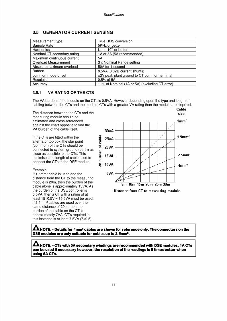
3.5.1 VA RATING OF THE CTS
The VA burden of the module on the CTs is 0.5VA. However depending upon the type and length of
cabling between the CTs and the module, CTs with a greater VA rating than the module are required.
The distance between the CTs and themeasuring module should beestimated and cross-referencedagainst the chart opposite to find theVA burden of the cable itself.
If the CTs are fitted within thealternator top box, the star point(common) of the CTs should beconnected to system ground (earth) asclose as possible to the CTs. This
minimises the length of cable used toconnect the CTs to the DSE module.
Example.If 1.5mm² cable is used and thedistance from the CT to the measuringmodule is 20m, then the burden of thecable alone is approximately 15VA. Asthe burden of the DSE controller is0.5VA, then a CT with a rating of atleast 15+0.5V = 15.5VA must be used.If 2.5mm² cables are used over thesame distance of 20m, then the
burden of the cable on the CT isapproximately 7VA. CT’s required inthis instance is at least 7.5VA (7+0.5).
NOTE:NOTE:NOTE:NOTE: ---- Details for 4mm² cables are shown for reference only.Details for 4mm² cables are shown for reference only.Details for 4mm² cables are shown for reference only.Details for 4mm² cables are shown for reference only. The connectors on theThe connectors on theThe connectors on theThe connectors on the
DSE modules are only suitable for cables up to 2.5mm².DSE modules are only suitable for cables up to 2.5mm².DSE modules are only suitable for cables up to 2.5mm².DSE modules are only suitable for cables up to 2.5mm².
NOTE:NOTE:NOTE:NOTE: ---- CTs with 5A secondary windings are recommended with DSE modules. 1A CTsCTs with 5A secondary windings are recommended with DSE modules. 1A CTsCTs with 5A secondary windings are recommended with DSE modules. 1A CTsCTs with 5A secondary windings are recommended with DSE modules. 1A CTscan be used if necessary however, the resolution of the readings is 5 times better whencan be used if necessary however, the resolution of the readings is 5 times better whencan be used if necessary however, the resolution of the readings is 5 times better whencan be used if necessary however, the resolution of the readings is 5 times better whenusing 5Ausing 5Ausing 5Ausing 5A CTs.CTs.CTs.CTs.
7/14/2019 DEEP SEA 7420
http://slidepdf.com/reader/full/deep-sea-7420-56327e12a4616 12/114
Specification
12
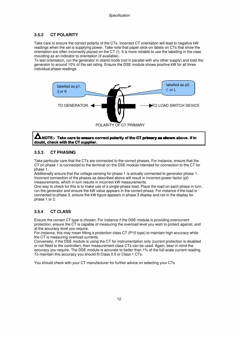
3.5.2 CT POLARITY
Take care to ensure the correct polarity of the CTs. Incorrect CT orientation will lead to negative kWreadings when the set is supplying power. Take note that paper stick-on labels on CTs that show theorientation are often incorrectly placed on the CT (!). It is more reliable to use the labelling in the case
moulding as an indicator to orientation (if available).To test orientation, run the generator in island mode (not in parallel with any other supply) and load thegenerator to around 10% of the set rating. Ensure the DSE module shows positive kW for all threeindividual phase readings.
TO GENERATOR TO LOAD SWITCH DEVICE
POLARITY OF CT PRIMARY
NOTE:NOTE:NOTE:NOTE:---- Take care to ensure correct polarity of the CT primary as showTake care to ensure correct polarity of the CT primary as showTake care to ensure correct polarity of the CT primary as showTake care to ensure correct polarity of the CT primary as shown above. If inn above. If inn above. If inn above. If indoubt, check with the CT supplier.doubt, check with the CT supplier.doubt, check with the CT supplier.doubt, check with the CT supplier.
3.5.3 CT PHASING
Take particular care that the CTs are connected to the correct phases. For instance, ensure that theCT on phase 1 is connected to the terminal on the DSE module intended for connection to the CT forphase 1.Additionally ensure that the voltage sensing for phase 1 is actually connected to generator phase 1.Incorrect connection of the phases as described above will result in incorrect power factor (pf)measurements, which in turn results in incorrect kW measurements.One way to check for this is to make use of a single-phase load. Place the load on each phase in turn,run the generator and ensure the kW value appears in the correct phase. For instance if the load isconnected to phase 3, ensure the kW figure appears in phase 3 display and not in the display forphase 1 or 2.
3.5.4 CT CLASS
Ensure the correct CT type is chosen. For instance if the DSE module is providing overcurrent
protection, ensure the CT is capable of measuring the overload level you wish to protect against, andat the accuracy level you require.For instance, this may mean fitting a protection class CT (P10 type) to maintain high accuracy whilethe CT is measuring overload currents.Conversely, if the DSE module is using the CT for instrumentation only (current protection is disabledor not fitted to the controller), then measurement class CTs can be used. Again, bear in mind theaccuracy you require. The DSE module is accurate to better than 1% of the full-scale current reading.To maintain this accuracy you should fit Class 0.5 or Class 1 CTs.
You should check with your CT manufacturer for further advice on selecting your CTs
labelled as p1,
k or K
labelled as p2,
l or L
7/14/2019 DEEP SEA 7420
http://slidepdf.com/reader/full/deep-sea-7420-56327e12a4616 13/114
Specification
13
3.6 INPUTS
3.6.1 DIGITAL INPUTS
Number 11 configurable inputsArrangement Contact between terminal and ground
Low level threshold 2.1V minimumHigh level threshold 6.6V maximumMaximum input voltage +50V DC with respect to plant supply negativeMinimum input voltage -24V DC with respect to plant supply negativeContact wetting current 7mA typicalOpen circuit voltage 12V typical
3.6.2 ANALOGUE INPUTS
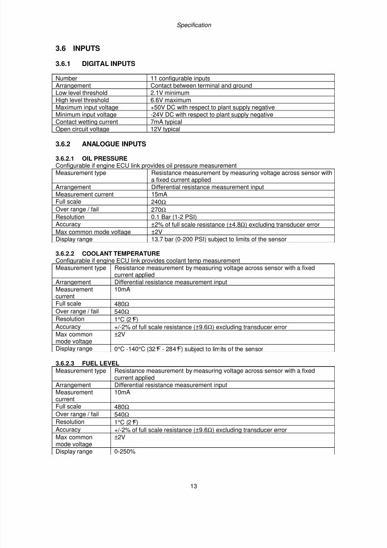
3.6.2.1 OIL PRESSUREConfigurable if engine ECU link provides oil pressure measurementMeasurement type Resistance measurement by measuring voltage across sensor with
a fixed current appliedArrangement Differential resistance measurement inputMeasurement current 15mAFull scale 240Ω Over range / fail 270Ω Resolution 0.1 Bar (1-2 PSI)Accuracy ±2% of full scale resistance (±4.8Ω) excluding transducer errorMax common mode voltage ±2VDisplay range 13.7 bar (0-200 PSI) subject to limits of the sensor
3.6.2.2 COOLANT TEMPERATUREConfigurable if engine ECU link provides coolant temp measurementMeasurement type Resistance measurement by measuring voltage across sensor with a fixed
current appliedArrangement Differential resistance measurement inputMeasurementcurrent
10mA
Full scale 480Ω Over range / fail 540Ω Resolution 1°C (2°F)Accuracy +/-2% of full scale resistance (±9.6Ω) excluding transducer errorMax commonmode voltage
±2V
Display range 0°C -140°C (32°F - 284°F) subject to limits of the sensor
3.6.2.3 FUEL LEVELMeasurement type Resistance measurement by measuring voltage across sensor with a fixed
current appliedArrangement Differential resistance measurement inputMeasurementcurrent
10mA
Full scale 480Ω Over range / fail 540Ω Resolution 1°C (2°F)Accuracy +/-2% of full scale resistance (±9.6Ω) excluding transducer errorMax commonmode voltage
±2V
Display range 0-250%
7/14/2019 DEEP SEA 7420
http://slidepdf.com/reader/full/deep-sea-7420-56327e12a4616 14/114
Specification
14
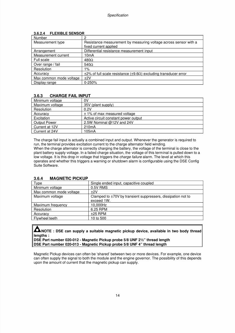
3.6.2.4 FLEXIBLE SENSORNumber 2Measurement type Resistance measurement by measuring voltage across sensor with a
fixed current appliedArrangement Differential resistance measurement input
Measurement current 10mAFull scale 480Ω Over range / fail 540Ω Resolution 1%Accuracy ±2% of full scale resistance (±9.6Ω) excluding transducer errorMax common mode voltage ±2VDisplay range 0-250%
3.6.3 CHARGE FAIL INPUTMinimum voltage 0VMaximum voltage 35V (plant supply)
Resolution 0.2VAccuracy ± 1% of max measured voltageExcitation Active circuit constant power outputOutput Power 2.5W Nominal @12V and 24VCurrent at 12V 210mACurrent at 24V 105mA
The charge fail input is actually a combined input and output. Whenever the generator is required torun, the terminal provides excitation current to the charge alternator field winding.When the charge alternator is correctly charging the battery, the voltage of the terminal is close to theplant battery supply voltage. In a failed charge situation, the voltage of this terminal is pulled down to alow voltage. It is this drop in voltage that triggers the charge failure alarm. The level at which thisoperates and whether this triggers a warning or shutdown alarm is configurable using the DSE Config
Suite Software.
3.6.4 MAGNETIC PICKUPType Single ended input, capacitive coupledMinimum voltage 0.5V RMSMax common mode voltage ±2VMaximum voltage Clamped to ±70V by transient suppressers, dissipation not to
exceed 1W.Maximum frequency 10,000HzResolution 6.25 RPMAccuracy ±25 RPMFlywheel teeth 10 to 500
NOTE : DSE can supply a suitable magnetic pickup device, available in two body threadlengths :DSE Part number 020-012 - Magnetic Pickup probe 5/8 UNF 2½” thread lengthDSE Part number 020-013 - Magnetic Pickup probe 5/8 UNF 4” thread length
Magnetic Pickup devices can often be ‘shared’ between two or more devices. For example, one devicecan often supply the signal to both the module and the engine governor. The possibility of this dependsupon the amount of current that the magnetic pickup can supply.
7/14/2019 DEEP SEA 7420
http://slidepdf.com/reader/full/deep-sea-7420-56327e12a4616 15/114
Specification
15
3.7 OUTPUTS
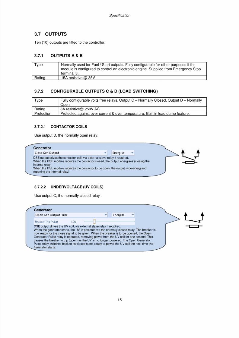
Ten (10) outputs are fitted to the controller.
3.7.1 OUTPUTS A & B
Type Normally used for Fuel / Start outputs. Fully configurable for other purposes if themodule is configured to control an electronic engine. Supplied from Emergency Stopterminal 3.
Rating 15A resistive @ 35V
3.7.2 CONFIGURABLE OUTPUTS C & D (LOAD SWITCHING)
Type Fully configurable volts free relays. Output C – Normally Closed, Output D – NormallyOpen
Rating 8A resistive@ 250V ACProtection Protected against over current & over temperature. Built in load dump feature.
3.7.2.1 CONTACTOR COILS
Use output D, the normally open relay:
3.7.2.2 UNDERVOLTAGE (UV COILS)
Use output C, the normally closed relay :
Generator
DSE output drives the contactor coil, via external slave relay if required.When the DSE module requires the contactor closed, the output energises (closing theinternal relay)
When the DSE module requires the contactor to be open, the output is de-energised(opening the internal relay)
Generator
DSE output drives the UV coil, via external slave relay if required.When the generator starts, the UV is powered via the normally closed relay. The breaker isnow ready for the close signal to be given. When the breaker is to be opened, the OpenGenerator Pulse relay is operated, removing power from the UV coil for one second. This causes the breaker to trip (open) as the UV is no longer powered. The Open GeneratorPulse relay switches back to its closed state, ready to power the UV coil the next time the
enerator starts.
7/14/2019 DEEP SEA 7420
http://slidepdf.com/reader/full/deep-sea-7420-56327e12a4616 16/114
Specification
16
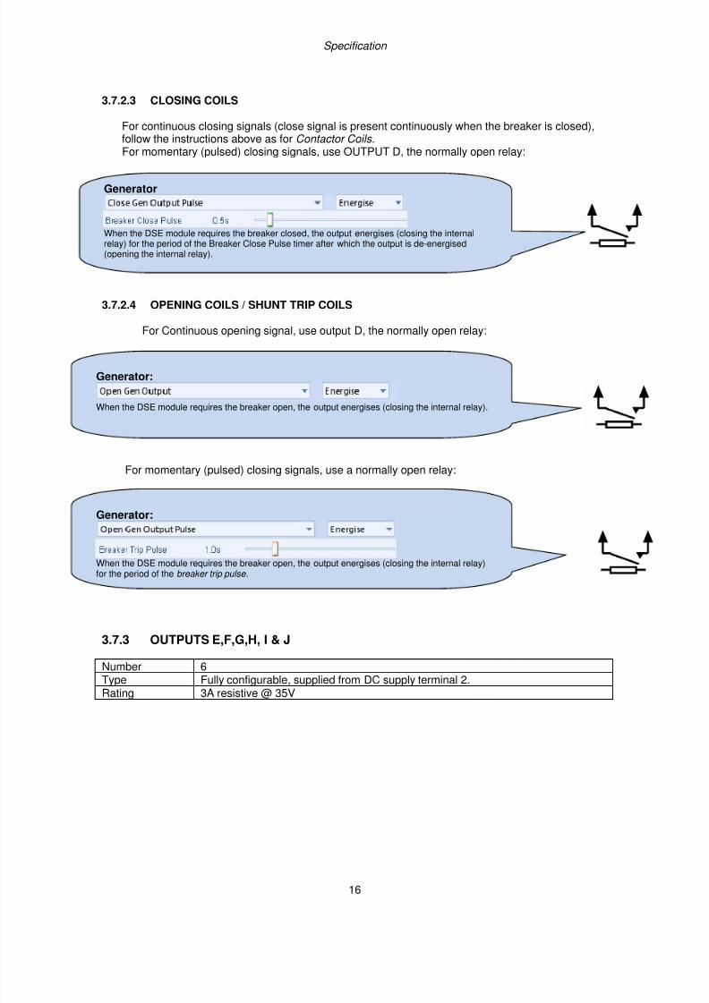
3.7.2.3 CLOSING COILS
For continuous closing signals (close signal is present continuously when the breaker is closed),follow the instructions above as for Contactor Coils .For momentary (pulsed) closing signals, use OUTPUT D, the normally open relay:
3.7.2.4 OPENING COILS / SHUNT TRIP COILS
For Continuous opening signal, use output D, the normally open relay:
For momentary (pulsed) closing signals, use a normally open relay:
3.7.3 OUTPUTS E,F,G,H, I & J
Number 6Type Fully configurable, supplied from DC supply terminal 2.Rating 3A resistive @ 35V
Generator:
When the DSE module requires the breaker open, the output energises (closing the internal relay).
Generator:
When the DSE module requires the breaker open, the output energises (closing the internal relay)for the period of the breaker trip pulse .
Generator
When the DSE module requires the breaker closed, the output energises (closing the internalrelay) for the period of the Breaker Close Pulse timer after which the output is de-energised(opening the internal relay).
7/14/2019 DEEP SEA 7420
http://slidepdf.com/reader/full/deep-sea-7420-56327e12a4616 17/114
Specification
17
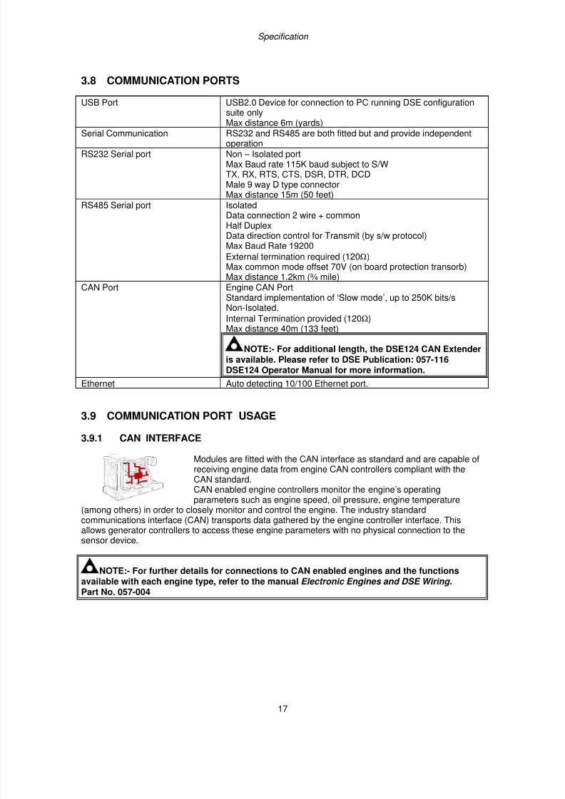
3.8 COMMUNICATION PORTS
USB Port USB2.0 Device for connection to PC running DSE configurationsuite onlyMax distance 6m (yards)
Serial Communication RS232 and RS485 are both fitted but and provide independentoperation
RS232 Serial port Non – Isolated portMax Baud rate 115K baud subject to S/WTX, RX, RTS, CTS, DSR, DTR, DCDMale 9 way D type connectorMax distance 15m (50 feet)
RS485 Serial port IsolatedData connection 2 wire + commonHalf DuplexData direction control for Transmit (by s/w protocol)Max Baud Rate 19200
External termination required (120Ω)
Max common mode offset 70V (on board protection transorb)Max distance 1.2km (¾ mile)
CAN Port Engine CAN PortStandard implementation of ‘Slow mode’, up to 250K bits/sNon-Isolated.
Internal Termination provided (120Ω)Max distance 40m (133 feet)
NOTE:- For additional length, the DSE124 CAN Extenderis available. Please refer to DSE Publication: 057-116DSE124 Operator Manual for more information.
Ethernet Auto detecting 10/100 Ethernet port.
3.9 COMMUNICATION PORT USAGE
3.9.1 CAN INTERFACE
Modules are fitted with the CAN interface as standard and are capable ofreceiving engine data from engine CAN controllers compliant with theCAN standard.CAN enabled engine controllers monitor the engine’s operatingparameters such as engine speed, oil pressure, engine temperature
(among others) in order to closely monitor and control the engine. The industry standardcommunications interface (CAN) transports data gathered by the engine controller interface. This
allows generator controllers to access these engine parameters with no physical connection to thesensor device.
NOTE:- For further details for connections to CAN enabled engines and the functionsavailable with each engine type, refer to the manual Electronic Engines and DSE Wiring. Part No. 057-004
7/14/2019 DEEP SEA 7420
http://slidepdf.com/reader/full/deep-sea-7420-56327e12a4616 18/114
Specification
18
3.9.2 USB CONNECTION
The USB port is provided to give a simple means of connection between a PC and the controller.Using the DSE Configuration Suite Software, the operator is then able to control the module, startingor stopping the generator, selecting operating modes, etc.
Additionally, the various operating parameters (such as output volts, oil pressure, etc.) of the remotegenerator are available to be viewed or changed.
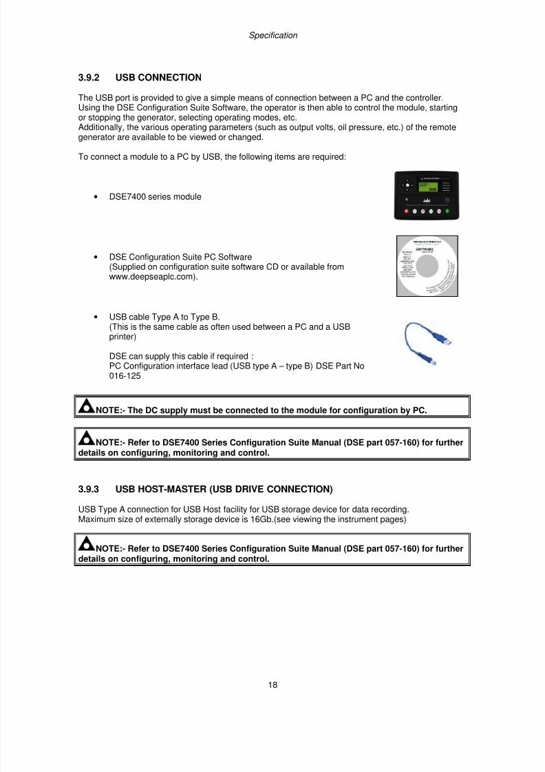
To connect a module to a PC by USB, the following items are required:
• DSE7400 series module
• DSE Configuration Suite PC Software(Supplied on configuration suite software CD or available fromwww.deepseaplc.com).
• USB cable Type A to Type B.(This is the same cable as often used between a PC and a USBprinter)
DSE can supply this cable if required :PC Configuration interface lead (USB type A – type B) DSE Part No016-125
NOTE:- The DC supply must be connected to the module for configuration by PC.
NOTE:- Refer to DSE7400 Series Configuration Suite Manual (DSE part 057-160) for furtherdetails on configuring, monitoring and control.
3.9.3 USB HOST-MASTER (USB DRIVE CONNECTION)
USB Type A connection for USB Host facility for USB storage device for data recording.Maximum size of externally storage device is 16Gb.(see viewing the instrument pages)
NOTE:- Refer to DSE7400 Series Configuration Suite Manual (DSE part 057-160) for furtherdetails on configuring, monitoring and control.
7/14/2019 DEEP SEA 7420
http://slidepdf.com/reader/full/deep-sea-7420-56327e12a4616 19/114
Specification
19
3.9.4 RS232
The RS232 port on the controller supports the Modbus RTU protocol.The Gencomm register table for the controller is available upon request from the DSE TechnicalSupport Department.
RS232 is for short distance communication (max 15m) and is typically used to connect the controller toa telephone or GSM modem for more remote communications.
Many PCs are not fitted with an internal RS232 serial port. DSE DOES NOT recommend the use ofUSB to RS232 convertors but can recommend PC add-ons to provide the computer with an RS232port.
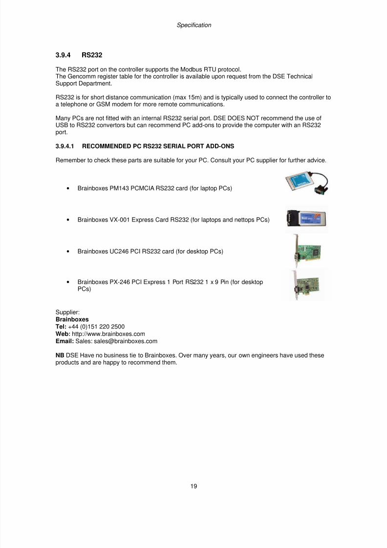
3.9.4.1 RECOMMENDED PC RS232 SERIAL PORT ADD-ONS
Remember to check these parts are suitable for your PC. Consult your PC supplier for further advice.
• Brainboxes PM143 PCMCIA RS232 card (for laptop PCs)
• Brainboxes VX-001 Express Card RS232 (for laptops and nettops PCs)
• Brainboxes UC246 PCI RS232 card (for desktop PCs)
• Brainboxes PX-246 PCI Express 1 Port RS232 1 x 9 Pin (for desktopPCs)
Supplier:BrainboxesTel: +44 (0)151 220 2500Web: http://www.brainboxes.comEmail: Sales: [email protected]
NB DSE Have no business tie to Brainboxes. Over many years, our own engineers have used these
products and are happy to recommend them.
7/14/2019 DEEP SEA 7420
http://slidepdf.com/reader/full/deep-sea-7420-56327e12a4616 20/114
Specification
20
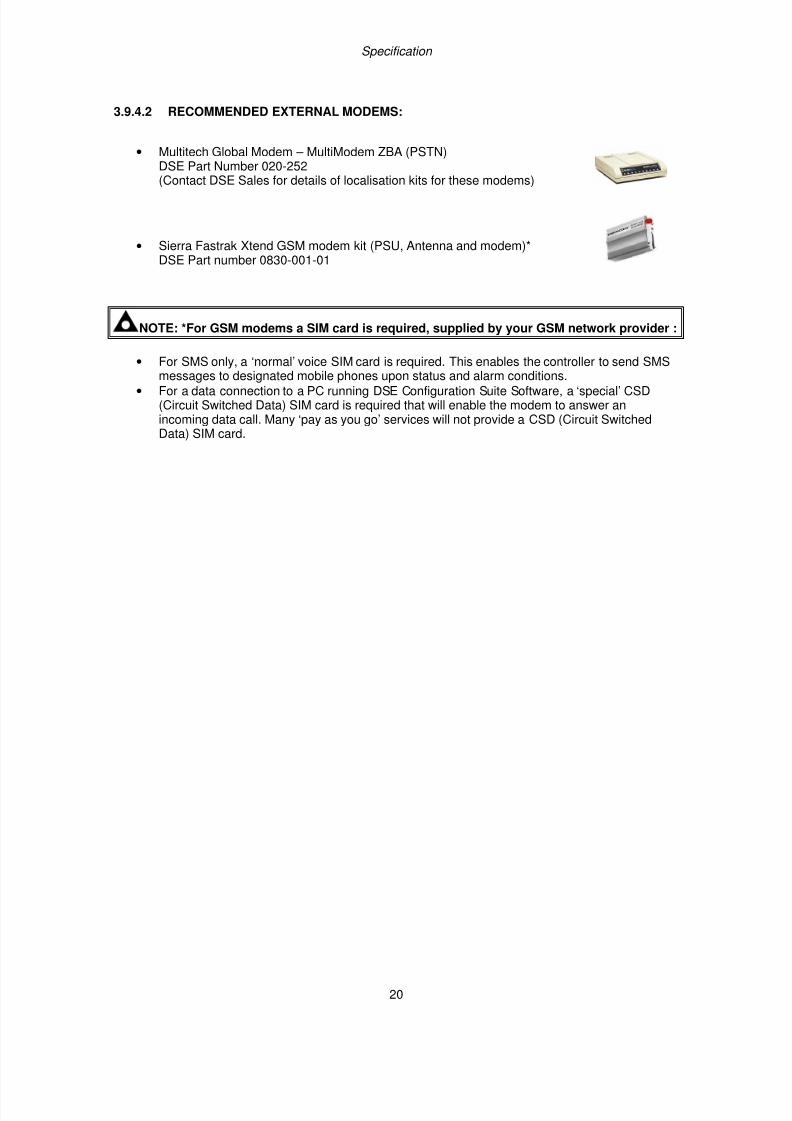
3.9.4.2 RECOMMENDED EXTERNAL MODEMS:
• Multitech Global Modem – MultiModem ZBA (PSTN)DSE Part Number 020-252
(Contact DSE Sales for details of localisation kits for these modems)
• Sierra Fastrak Xtend GSM modem kit (PSU, Antenna and modem)*DSE Part number 0830-001-01
NOTE: *For GSM modems a SIM card is required, supplied by your GSM network provider :
• For SMS only, a ‘normal’ voice SIM card is required. This enables the controller to send SMSmessages to designated mobile phones upon status and alarm conditions.
• For a data connection to a PC running DSE Configuration Suite Software, a ‘special’ CSD(Circuit Switched Data) SIM card is required that will enable the modem to answer anincoming data call. Many ‘pay as you go’ services will not provide a CSD (Circuit SwitchedData) SIM card.
7/14/2019 DEEP SEA 7420
http://slidepdf.com/reader/full/deep-sea-7420-56327e12a4616 21/114
Specification
21
3.9.5 RS485
The RS485 port on the series controller supports the Modbus RTU protocol.The DSE Gencomm register table for the controller is available upon request from the DSE TechnicalSupport Department.
RS485 is used for point-to-point cable connection of more than one device (maximum 32 devices) andallows for connection to PCs, PLCs and Building Management Systems (to name just a few devices).
One advantage of the RS485 interface is the large distance specification (1.2km when using Belden9841 (or equivalent) cable. This allows for a large distance between the module and a PC running theDSE Configuration Suite software. The operator is then able to control the module, starting or stoppingthe generator, selecting operating modes, etc.The various operating parameters (such as output volts, oil pressure, etc.) of the remote generator canbe viewed or changed.
NOTE:- For a single module to PC connection and distances up to 6m (8yds) the USBconnection method is more suitable and provides for a lower cost alternative to RS485 (which
is more suited to longer distance connections).
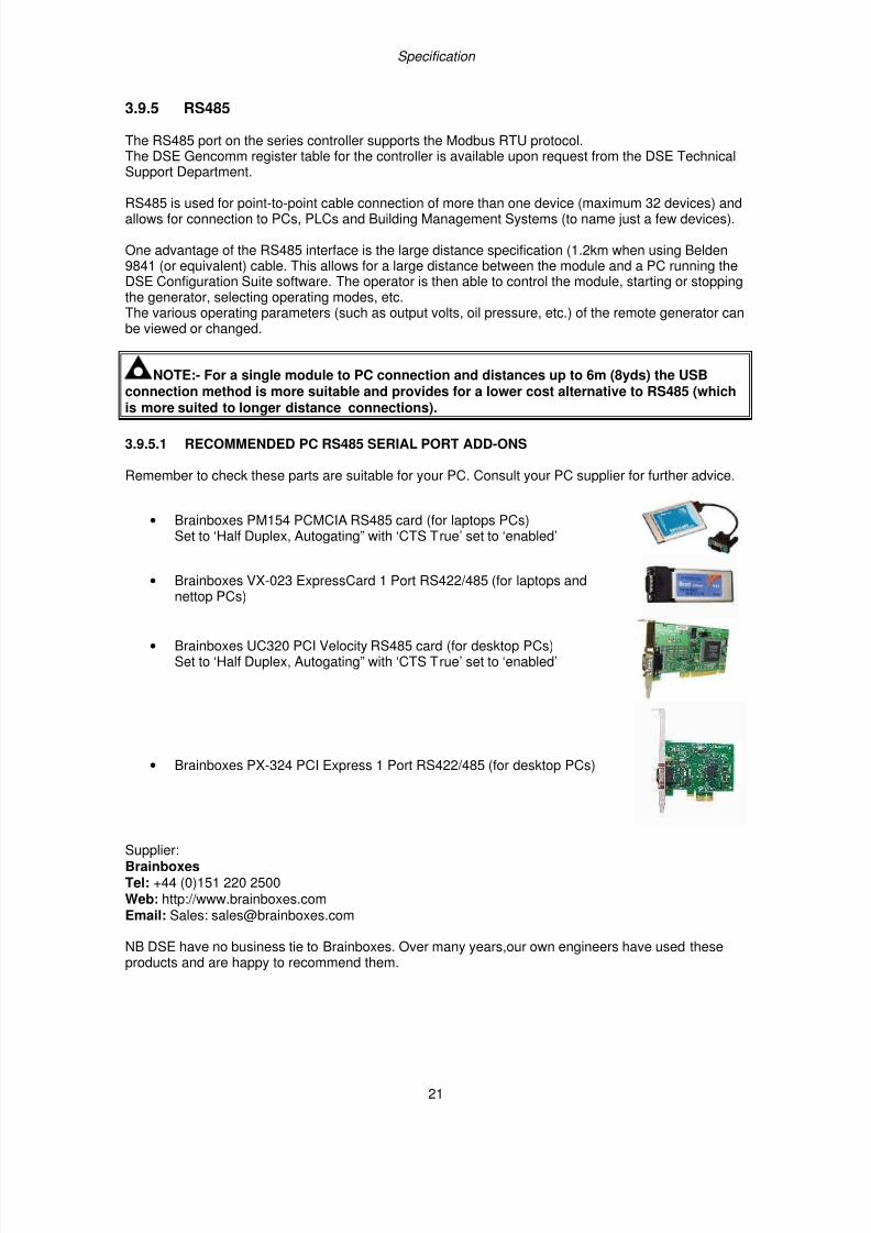
3.9.5.1 RECOMMENDED PC RS485 SERIAL PORT ADD-ONS
Remember to check these parts are suitable for your PC. Consult your PC supplier for further advice.
• Brainboxes PM154 PCMCIA RS485 card (for laptops PCs)Set to ‘Half Duplex, Autogating” with ‘CTS True’ set to ‘enabled’
• Brainboxes VX-023 ExpressCard 1 Port RS422/485 (for laptops andnettop PCs)
• Brainboxes UC320 PCI Velocity RS485 card (for desktop PCs)Set to ‘Half Duplex, Autogating” with ‘CTS True’ set to ‘enabled’
• Brainboxes PX-324 PCI Express 1 Port RS422/485 (for desktop PCs)
Supplier:BrainboxesTel: +44 (0)151 220 2500Web: http://www.brainboxes.comEmail: Sales: [email protected]
NB DSE have no business tie to Brainboxes. Over many years,our own engineers have used theseproducts and are happy to recommend them.
7/14/2019 DEEP SEA 7420
http://slidepdf.com/reader/full/deep-sea-7420-56327e12a4616 22/114
Specification
22
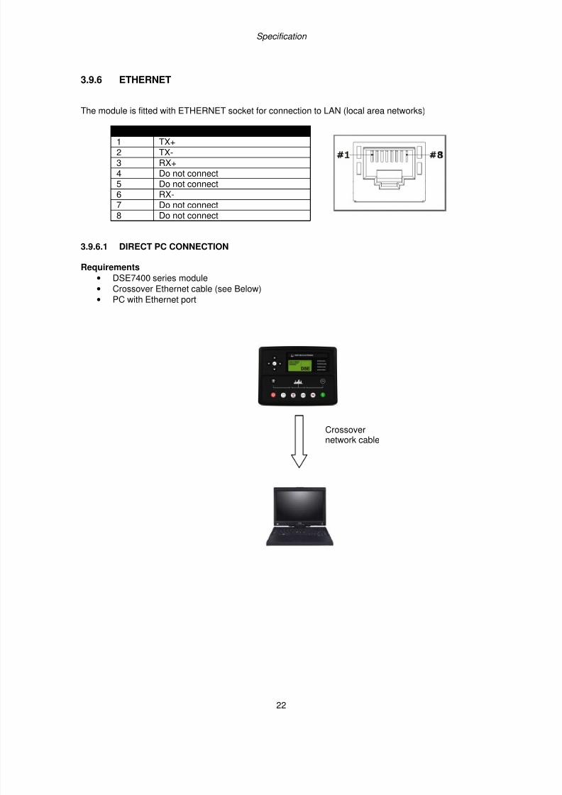
3.9.6 ETHERNET
The module is fitted with ETHERNET socket for connection to LAN (local area networks)
Description 1 TX+
2 TX- 3 RX+
4 Do not connect 5 Do not connect 6 RX- 7 Do not connect 8 Do not connect
3.9.6.1 DIRECT PC CONNECTION
Requirements
• DSE7400 series module
• Crossover Ethernet cable (see Below)
• PC with Ethernet port
Crossovernetwork cable
7/14/2019 DEEP SEA 7420
http://slidepdf.com/reader/full/deep-sea-7420-56327e12a4616 23/114
Specification
23
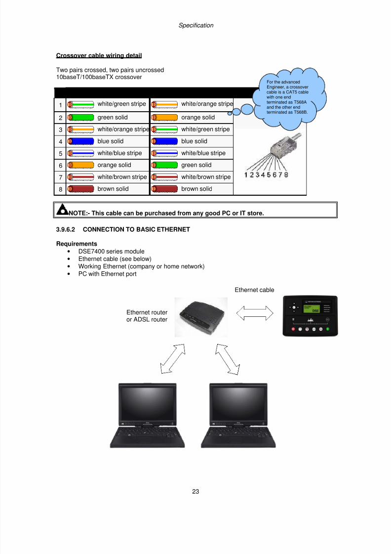
Crossover cable wiring detail
Two pairs crossed, two pairs uncrossed10baseT/100baseTX crossover
Pin Connection 1 (T568A) Connection 2 (T568B)
1 white/green stripe white/orange stripe
2 green solid orange solid
3 white/orange stripe white/green stripe
4 blue solid blue solid
5 white/blue stripe white/blue stripe
6 orange solid green solid
7 white/brown stripe white/brown stripe
8 brown solid brown solid
NOTE:- This cable can be purchased from any good PC or IT store. 3.9.6.2 CONNECTION TO BASIC ETHERNET
Requirements
• DSE7400 series module
• Ethernet cable (see below)
• Working Ethernet (company or home network)
• PC with Ethernet port
For the advancedEngineer, a crossover
cable is a CAT5 cablewith one endterminated as T568Aand the other endterminated as T568B.
Ethernet routeror ADSL router
Ethernet cable
7/14/2019 DEEP SEA 7420
http://slidepdf.com/reader/full/deep-sea-7420-56327e12a4616 24/114
Specification
24
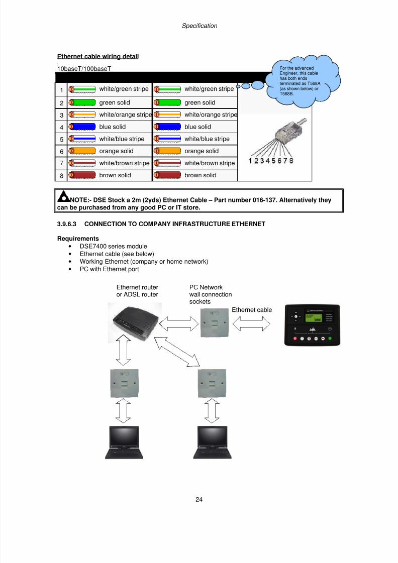
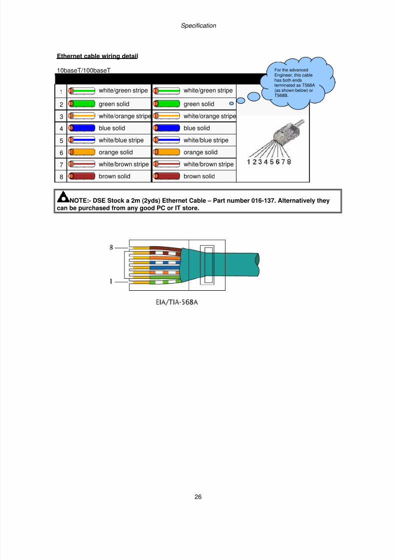
Ethernet cable wiring detail.
10baseT/100baseT
Pin Connection 1 (T568A) Connection 2 (T568A)
1 white/green stripe white/green stripe
2 green solid green solid
3 white/orange stripe white/orange stripe
4 blue solid blue solid
5 white/blue stripe white/blue stripe
6 orange solid orange solid
7 white/brown stripe white/brown stripe
8 brown solid brown solid
NOTE:- DSE Stock a 2m (2yds) Ethernet Cable – Part number 016-137. Alternatively theycan be purchased from any good PC or IT store.
3.9.6.3 CONNECTION TO COMPANY INFRASTRUCTURE ETHERNET
Requirements
• DSE7400 series module
• Ethernet cable (see below)
• Working Ethernet (company or home network)
• PC with Ethernet port
For the advancedEngineer, this cablehas both endsterminated as T568A(as shown below) or
T568B.
Ethernet cable
PC Networkwall connectionsockets
Ethernet routeror ADSL router
7/14/2019 DEEP SEA 7420
http://slidepdf.com/reader/full/deep-sea-7420-56327e12a4616 25/114
Specification
25
Ethernet cable wiring detail
10baseT/100baseT
Pin Connection 1 (T568A) Connection 2 (T568A)
1 white/green stripe white/green stripe
2 green solid green solid
3 white/orange stripe white/orange stripe
4 blue solid blue solid
5 white/blue stripe white/blue stripe
6 orange solid orange solid
7 white/brown stripe white/brown stripe
8 brown solid brown solid
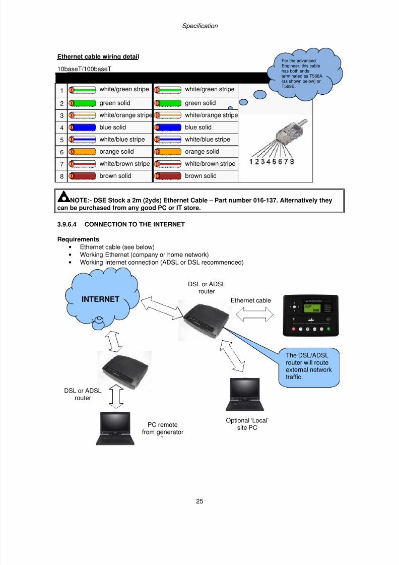
NOTE:- DSE Stock a 2m (2yds) Ethernet Cable – Part number 016-137. Alternatively theycan be purchased from any good PC or IT store. 3.9.6.4 CONNECTION TO THE INTERNET
Requirements
• Ethernet cable (see below)
• Working Ethernet (company or home network)
• Working Internet connection (ADSL or DSL recommended)
For the advancedEngineer, this cablehas both endsterminated as T568A(as shown below) orT568B.
DSL or ADSLrouter
Optional ‘Local’site PC
INTERNET
DSL or ADSLrouter
PC remotefrom generator
The DSL/ADSLrouter will routeexternal networktraffic.
Ethernet cable
7/14/2019 DEEP SEA 7420
http://slidepdf.com/reader/full/deep-sea-7420-56327e12a4616 26/114
Specification
26
Ethernet cable wiring detail
10baseT/100baseT
Pin Connection 1 (T568A) Connection 2 (T568A)
1 white/green stripe white/green stripe
2 green solid green solid
3 white/orange stripe white/orange stripe
4 blue solid blue solid
5 white/blue stripe white/blue stripe
6 orange solid orange solid
7 white/brown stripe white/brown stripe
8 brown solid brown solid
NOTE:- DSE Stock a 2m (2yds) Ethernet Cable – Part number 016-137. Alternatively theycan be purchased from any good PC or IT store.
For the advancedEngineer, this cablehas both endsterminated as T568A
(as shown below) orT568B.
7/14/2019 DEEP SEA 7420
http://slidepdf.com/reader/full/deep-sea-7420-56327e12a4616 27/114
Specification
27
3.9.6.5 FIREWALL CONFIGURATION FOR INTERNET ACCESS
As modem/routers differ enormously in their configuration, it is not possible for DSE to give a completeguide to their use with the module. However it is possible to give a description of the requirements ingeneric terms. For details of how to achieve the connection to your modem/router you are referred to
the supplier of your modem/router equipment.
The module makes its data available over Modbus TCP and as such communicates over the Ethernetusing a Port configured via the DSE Configuration Suite software..
You must configure your modem/router to allow inbound traffic on this port. For more information youare referred to your WAN interface device (modem/router) manufacturer.
It is also important to note that if the port assigned (setting from software “Modbus Port Number”) isalready in use on the LAN, the module cannot be used and another port must be used .
Outgoing Firewall rule
As the module makes its user interface available to standard web browsers, all communication usesthe chosen port. It is usual for a firewall to make the same port outgoing open for communication.
Incoming traffic (virtual server)
Network Address and Port Translation (NAPT) allows a single device, such as the modem/routergateway, to act as an agent between the Internet (or "public external network") and a local (or "internalprivate") network. This means that only a single, unique IP address is required to represent an entiregroup of computers.
For our application, this means that the WAN IP address of the modem/router is the IP address we
need to access the site from an external (internet) location.
When the requests reach the modem/router, we want this passed to a ‘virtual server’ for handling, inour case this is the module.
Result : Traffic arriving from the WAN (internet) on port xxx is automatically sent to IP address setwithin the configuration software on the LAN for handling.
NOTE:- Refer to DSE7400 Series Configuration Suite Manual (DSE part 057-160) for furtherdetails on configuring, monitoring and control.
7/14/2019 DEEP SEA 7420
http://slidepdf.com/reader/full/deep-sea-7420-56327e12a4616 28/114
Specification
28
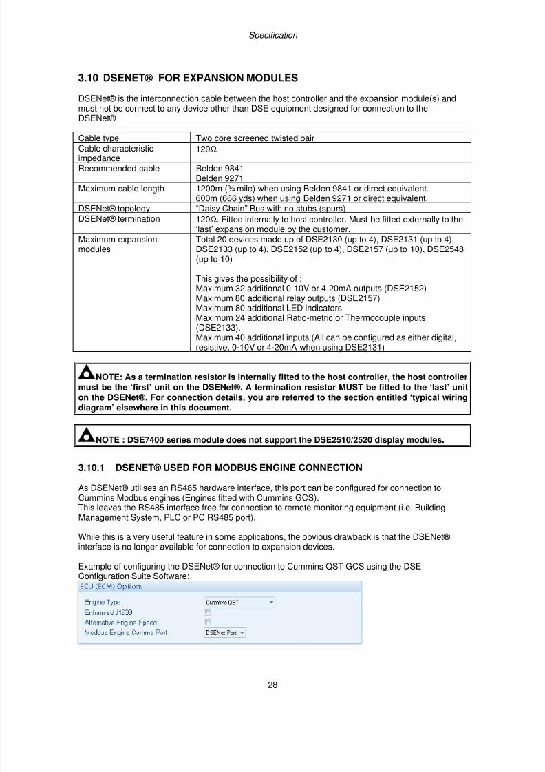
3.10 DSENET® FOR EXPANSION MODULES
DSENet® is the interconnection cable between the host controller and the expansion module(s) andmust not be connect to any device other than DSE equipment designed for connection to theDSENet®
Cable type Two core screened twisted pairCable characteristicimpedance
120Ω
Recommended cable Belden 9841Belden 9271
Maximum cable length 1200m (¾ mile) when using Belden 9841 or direct equivalent.600m (666 yds) when using Belden 9271 or direct equivalent.
DSENet® topology “Daisy Chain” Bus with no stubs (spurs)DSENet® termination 120Ω. Fitted internally to host controller. Must be fitted externally to the
‘last’ expansion module by the customer.Maximum expansionmodules
Total 20 devices made up of DSE2130 (up to 4), DSE2131 (up to 4),DSE2133 (up to 4), DSE2152 (up to 4), DSE2157 (up to 10), DSE2548(up to 10)
This gives the possibility of :Maximum 32 additional 0-10V or 4-20mA outputs (DSE2152)Maximum 80 additional relay outputs (DSE2157)Maximum 80 additional LED indicatorsMaximum 24 additional Ratio-metric or Thermocouple inputs(DSE2133).Maximum 40 additional inputs (All can be configured as either digital,resistive, 0-10V or 4-20mA when using DSE2131)
NOTE: As a termination resistor is internally fitted to the host controller, the host controllermust be the ‘first’ unit on the DSENet®. A termination resistor MUST be fitted to the ‘last’ uniton the DSENet®. For connection details, you are referred to the section entitled ‘typical wiringdiagram’ elsewhere in this document.
NOTE : DSE7400 series module does not support the DSE2510/2520 display modules.
3.10.1 DSENET® USED FOR MODBUS ENGINE CONNECTION
As DSENet® utilises an RS485 hardware interface, this port can be configured for connection toCummins Modbus engines (Engines fitted with Cummins GCS).
This leaves the RS485 interface free for connection to remote monitoring equipment (i.e. BuildingManagement System, PLC or PC RS485 port).
While this is a very useful feature in some applications, the obvious drawback is that the DSENet® interface is no longer available for connection to expansion devices.
Example of configuring the DSENet® for connection to Cummins QST GCS using the DSEConfiguration Suite Software:
7/14/2019 DEEP SEA 7420
http://slidepdf.com/reader/full/deep-sea-7420-56327e12a4616 29/114
Specification
29
3.11 SOUNDER
The module features an internal sounder to draw attention to warning, shutdown and electrical tripalarms.
Sounder level 64db @ 1m
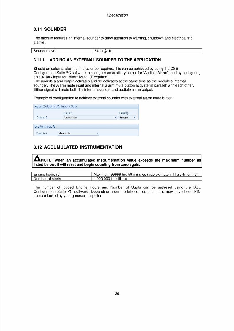
3.11.1 ADDING AN EXTERNAL SOUNDER TO THE APPLICATION
Should an external alarm or indicator be required, this can be achieved by using the DSEConfiguration Suite PC software to configure an auxiliary output for “Audible Alarm”, and by configuringan auxiliary input for “Alarm Mute” (if required).The audible alarm output activates and de-activates at the same time as the module’s internalsounder. The Alarm mute input and internal alarm mute button activate ‘in parallel’ with each other.Either signal will mute both the internal sounder and audible alarm output.
Example of configuration to achieve external sounder with external alarm mute button:
3.12 ACCUMULATED INSTRUMENTATION
NOTE: When an accumulated instrumentation value exceeds the maximum number as
listed below, it will reset and begin counting from zero again.
Engine hours run Maximum 99999 hrs 59 minutes (approximately 11yrs 4months)Number of starts 1,000,000 (1 million)
The number of logged Engine Hours and Number of Starts can be set/reset using the DSEConfiguration Suite PC software. Depending upon module configuration, this may have been PINnumber locked by your generator supplier
7/14/2019 DEEP SEA 7420
http://slidepdf.com/reader/full/deep-sea-7420-56327e12a4616 30/114
Specification
30
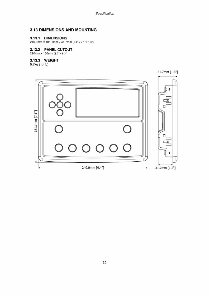
3.13 DIMENSIONS AND MOUNTING
3.13.1 DIMENSIONS240.0mm x 181.1mm x 41.7mm (9.4” x 7.1” x 1.6”)
3.13.2 PANEL CUTOUT220mm x 160mm (8.7” x 6.3”)
3.13.3 WEIGHT0.7kg (1.4lb)
7/14/2019 DEEP SEA 7420
http://slidepdf.com/reader/full/deep-sea-7420-56327e12a4616 31/114
Specification
31
3.13.4 FIXING CLIPS
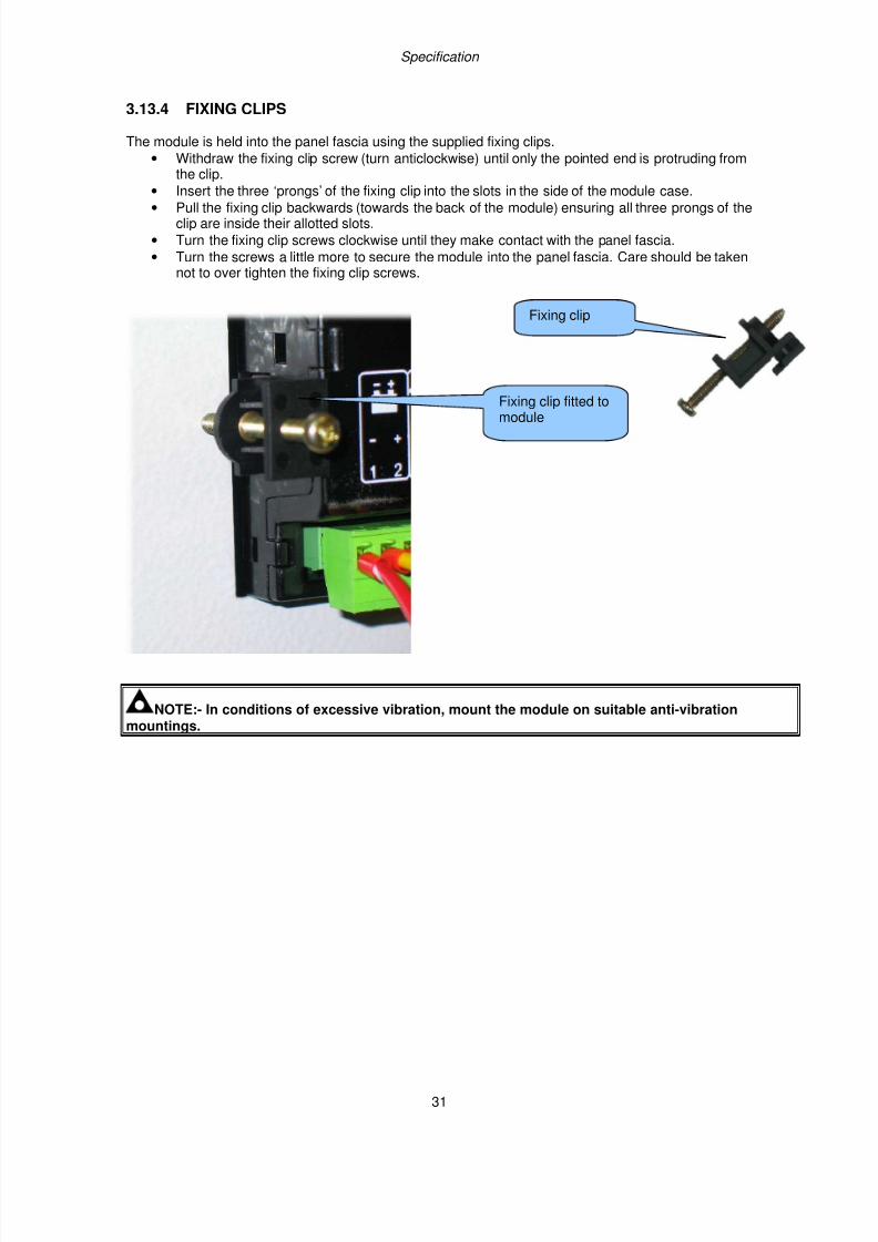
The module is held into the panel fascia using the supplied fixing clips.
• Withdraw the fixing clip screw (turn anticlockwise) until only the pointed end is protruding fromthe clip.
• Insert the three ‘prongs’ of the fixing clip into the slots in the side of the module case.
• Pull the fixing clip backwards (towards the back of the module) ensuring all three prongs of theclip are inside their allotted slots.
• Turn the fixing clip screws clockwise until they make contact with the panel fascia.
• Turn the screws a little more to secure the module into the panel fascia. Care should be takennot to over tighten the fixing clip screws.
NOTE:- In conditions of excessive vibration, mount the module on suitable anti-vibrationmountings.
Fixing clip fitted tomodule
Fixing clip
7/14/2019 DEEP SEA 7420
http://slidepdf.com/reader/full/deep-sea-7420-56327e12a4616 32/114
Specification
32
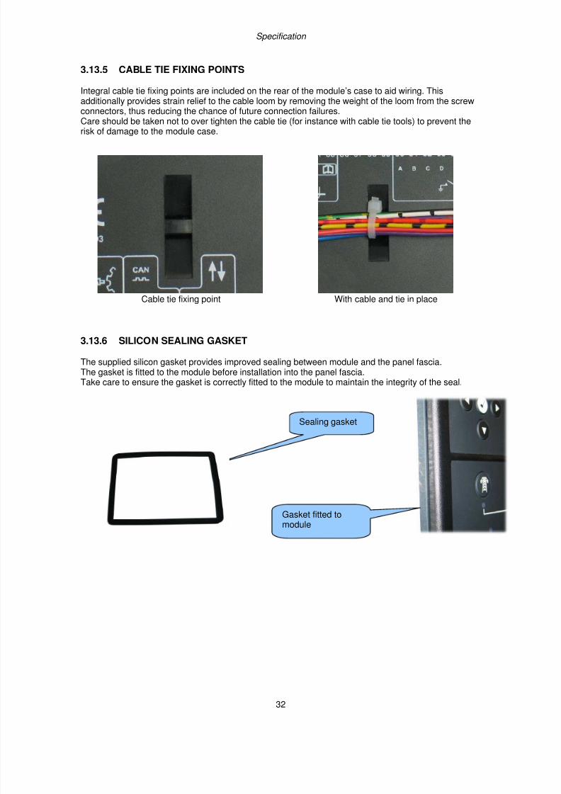
3.13.5 CABLE TIE FIXING POINTS
Integral cable tie fixing points are included on the rear of the module’s case to aid wiring. Thisadditionally provides strain relief to the cable loom by removing the weight of the loom from the screwconnectors, thus reducing the chance of future connection failures.Care should be taken not to over tighten the cable tie (for instance with cable tie tools) to prevent the
risk of damage to the module case.
Cable tie fixing point With cable and tie in place
3.13.6 SILICON SEALING GASKET
The supplied silicon gasket provides improved sealing between module and the panel fascia.The gasket is fitted to the module before installation into the panel fascia.Take care to ensure the gasket is correctly fitted to the module to maintain the integrity of the seal.
Gasket fitted to
module
Sealing gasket
7/14/2019 DEEP SEA 7420
http://slidepdf.com/reader/full/deep-sea-7420-56327e12a4616 33/114
Specification
33
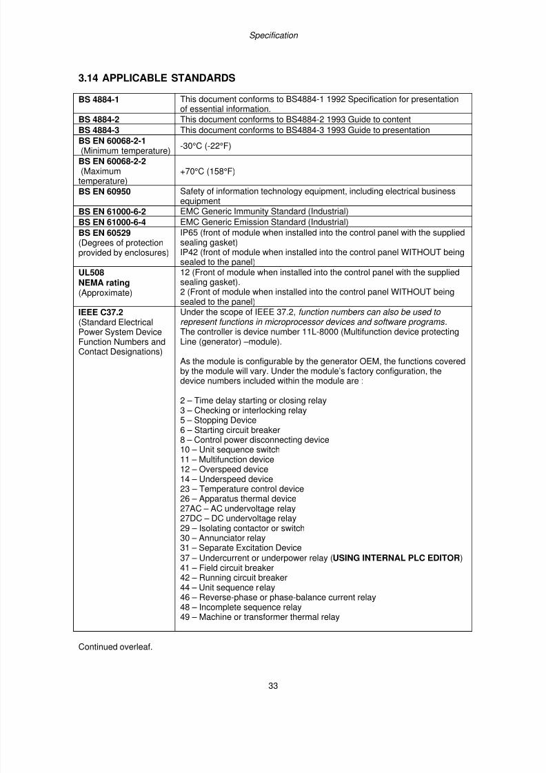
3.14 APPLICABLE STANDARDS
BS 4884-1 This document conforms to BS4884-1 1992 Specification for presentationof essential information.
BS 4884-2 This document conforms to BS4884-2 1993 Guide to content
BS 4884-3 This document conforms to BS4884-3 1993 Guide to presentationBS EN 60068-2-1(Minimum temperature)
-30°C (-22°F)
BS EN 60068-2-2(Maximumtemperature)
+70°C (158°F)
BS EN 60950 Safety of information technology equipment, including electrical businessequipment
BS EN 61000-6-2 EMC Generic Immunity Standard (Industrial)
BS EN 61000-6-4 EMC Generic Emission Standard (Industrial)
BS EN 60529 (Degrees of protection
provided by enclosures)
IP65 (front of module when installed into the control panel with the suppliedsealing gasket)
IP42 (front of module when installed into the control panel WITHOUT beingsealed to the panel)
UL508NEMA rating(Approximate)
12 (Front of module when installed into the control panel with the suppliedsealing gasket).2 (Front of module when installed into the control panel WITHOUT beingsealed to the panel)
IEEE C37.2(Standard ElectricalPower System DeviceFunction Numbers andContact Designations)
Under the scope of IEEE 37.2, function numbers can also be used to represent functions in microprocessor devices and software programs .The controller is device number 11L-8000 (Multifunction device protectingLine (generator) –module).
As the module is configurable by the generator OEM, the functions coveredby the module will vary. Under the module’s factory configuration, the
device numbers included within the module are :
2 – Time delay starting or closing relay3 – Checking or interlocking relay5 – Stopping Device6 – Starting circuit breaker8 – Control power disconnecting device10 – Unit sequence switch11 – Multifunction device12 – Overspeed device14 – Underspeed device23 – Temperature control device26 – Apparatus thermal device
27AC – AC undervoltage relay27DC – DC undervoltage relay29 – Isolating contactor or switch30 – Annunciator relay31 – Separate Excitation Device37 – Undercurrent or underpower relay (USING INTERNAL PLC EDITOR)41 – Field circuit breaker42 – Running circuit breaker44 – Unit sequence relay46 – Reverse-phase or phase-balance current relay48 – Incomplete sequence relay49 – Machine or transformer thermal relay
Continued overleaf.
7/14/2019 DEEP SEA 7420
http://slidepdf.com/reader/full/deep-sea-7420-56327e12a4616 34/114
Specification
34
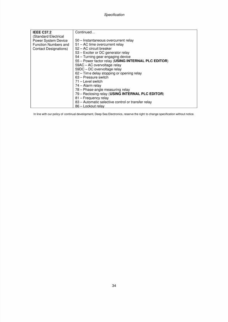
IEEE C37.2(Standard ElectricalPower System DeviceFunction Numbers andContact Designations)
Continued…
50 – Instantaneous overcurrent relay51 – AC time overcurrent relay52 – AC circuit breaker
53 – Exciter or DC generator relay54 – Turning gear engaging device55 – Power factor relay (USING INTERNAL PLC EDITOR)59AC – AC overvoltage relay59DC – DC overvoltage relay62 – Time delay stopping or opening relay63 – Pressure switch71 – Level switch74 – Alarm relay78 – Phase-angle measuring relay79 – Reclosing relay (USING INTERNAL PLC EDITOR)81 – Frequency relay83 – Automatic selective control or transfer relay
86 – Lockout relay
In line with our policy of continual development, Deep Sea Electronics, reserve the right to change specification without notice.
7/14/2019 DEEP SEA 7420
http://slidepdf.com/reader/full/deep-sea-7420-56327e12a4616 35/114
Specification
35
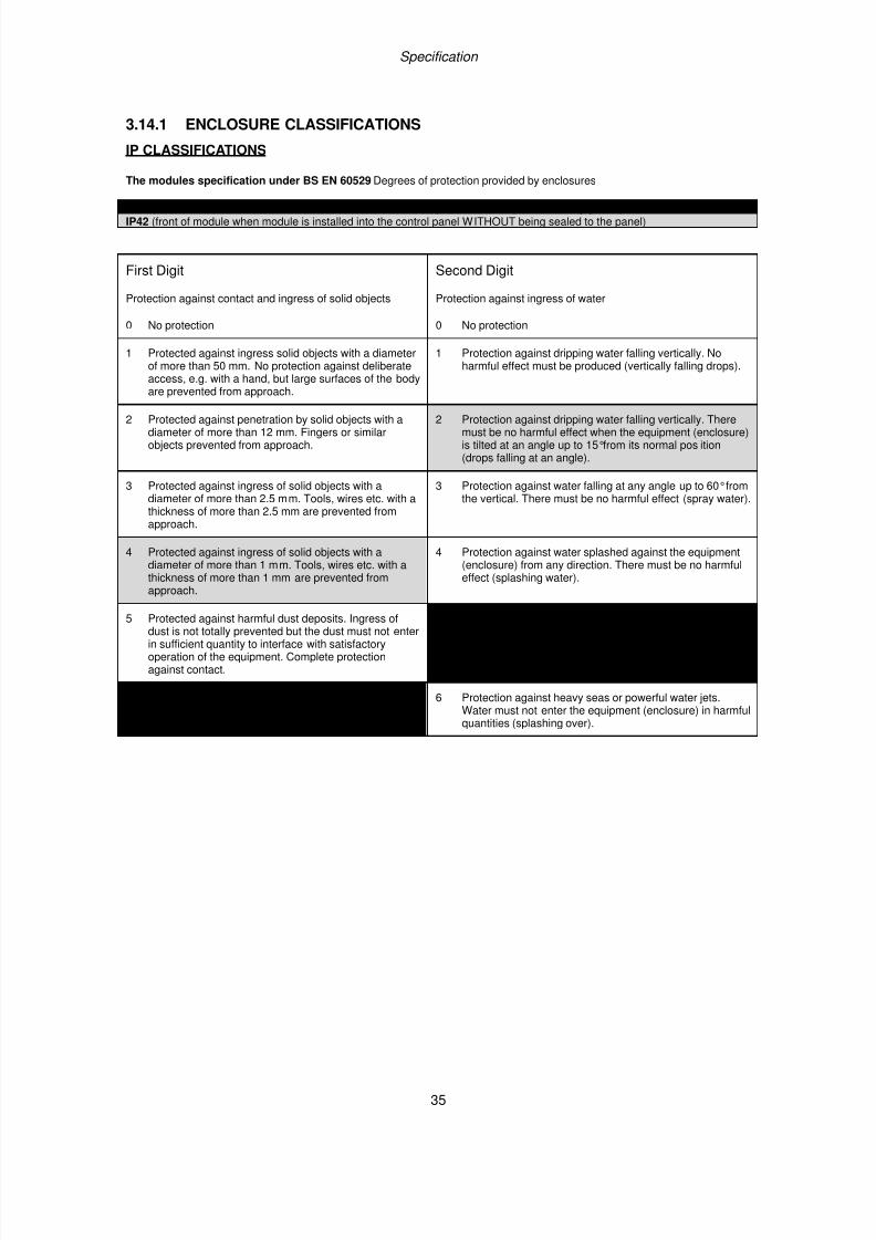
3.14.1 ENCLOSURE CLASSIFICATIONS
IP CLASSIFICATIONS
The modules specification under BS EN 60529 Degrees of protection provided by enclosures
IP65 (Front of module when module is installed into the control panel with the optional sealing gasket). IP42 (front of module when module is installed into the control panel WITHOUT being sealed to the panel)
First Digit Second Digit
Protection against contact and ingress of solid objects Protection against ingress of water
0 No protection 0 No protection
1 Protected against ingress solid objects with a diameterof more than 50 mm. No protection against deliberateaccess, e.g. with a hand, but large surfaces of the bodyare prevented from approach.
1 Protection against dripping water falling vertically. Noharmful effect must be produced (vertically falling drops).
2 Protected against penetration by solid objects with adiameter of more than 12 mm. Fingers or similarobjects prevented from approach.
2 Protection against dripping water falling vertically. Theremust be no harmful effect when the equipment (enclosure)is tilted at an angle up to 15°from its normal pos ition(drops falling at an angle).
3 Protected against ingress of solid objects with adiameter of more than 2.5 mm. Tools, wires etc. with athickness of more than 2.5 mm are prevented fromapproach.
3 Protection against water falling at any angle up to 60°fromthe vertical. There must be no harmful effect (spray water).
4 Protected against ingress of solid objects with adiameter of more than 1 mm. Tools, wires etc. with athickness of more than 1 mm are prevented fromapproach.
4 Protection against water splashed against the equipment(enclosure) from any direction. There must be no harmfuleffect (splashing water).
5 Protected against harmful dust deposits. Ingress ofdust is not totally prevented but the dust must not enterin sufficient quantity to interface with satisfactoryoperation of the equipment. Complete protectionagainst contact.
5 Protection against water projected from a nozzle againstthe equipment (enclosure) from any direction. There mustbe no harmful effect (water jet).
6 Protection against ingress of dust (dust tight).Complete protection against contact.
6 Protection against heavy seas or powerful water jets.Water must not enter the equipment (enclosure) in harmfulquantities (splashing over).
7/14/2019 DEEP SEA 7420
http://slidepdf.com/reader/full/deep-sea-7420-56327e12a4616 36/114
Specification
36
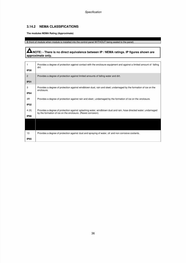
3.14.2 NEMA CLASSIFICATIONS
The modules NEMA Rating (Approximate)
12 (Front of module when module is installed into the control panel with the optional sealing gasket).
2 (front of module when module is installed into the control panel WITHOUT being sealed to the panel)
NOTE: - There is no direct equivalence between IP / NEMA ratings. IP figures shown areapproximate only.
1
IP30
Provides a degree of protection against contact with the enclosure equipment and against a limited amount of fallingdirt.
2
IP31
Provides a degree of protection against limited amounts of falling water and dirt.
3
IP64
Provides a degree of protection against windblown dust, rain and sleet; undamaged by the formation of ice on theenclosure.
3R
IP32
Provides a degree of protection against rain and sleet:; undamaged by the formation of ice on the enclosure.
4 (X)
IP66
Provides a degree of protection against splashing water, windblown dust and rain, hose directed water; undamagedby the formation of ice on the enclosure. (Resist corrosion).
12/12K
IP65
Provides a degree of protection against dust, falling dirt and dripping non corrosive liquids.
13
IP65
Provides a degree of protection against dust and spraying of water, oil and non corrosive coolants.
7/14/2019 DEEP SEA 7420
http://slidepdf.com/reader/full/deep-sea-7420-56327e12a4616 37/114
Installation – Terminal Description
37
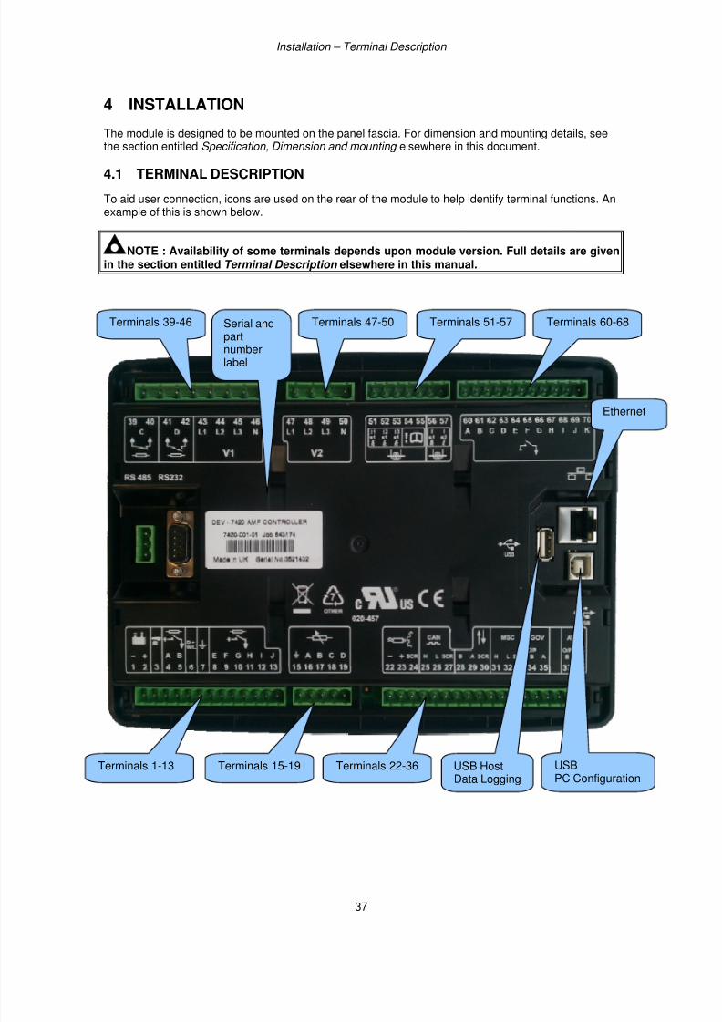
4 INSTALLATION
The module is designed to be mounted on the panel fascia. For dimension and mounting details, seethe section entitled Specification, Dimension and mounting elsewhere in this document.
4.1 TERMINAL DESCRIPTION
To aid user connection, icons are used on the rear of the module to help identify terminal functions. Anexample of this is shown below.
NOTE : Availability of some terminals depends upon module version. Full details are givenin the section entitled Terminal Description elsewhere in this manual.
Terminals 1-13 Terminals 15-19 Terminals 22-36
Terminals 39-46 Terminals 47-50 Terminals 51-57 Terminals 60-68
USBPC Configuration
USB HostData Logging
Serial and
partnumberlabel
Ethernet
7/14/2019 DEEP SEA 7420
http://slidepdf.com/reader/full/deep-sea-7420-56327e12a4616 38/114
Installation – Terminal Description
38
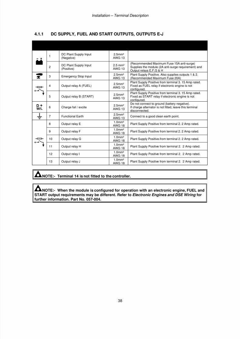
4.1.1 DC SUPPLY, FUEL AND START OUTPUTS, OUTPUTS E-J
PINNo
DESCRIPTION CABLESIZE
NOTES
1DC Plant Supply Input(Negative)
2.5mm²AWG 13
2DC Plant Supply Input(Positive)
2.5 mm²AWG 13
(Recommended Maximum Fuse 15A anti-surge)Supplies the module (2A anti-surge requirement) andOutput relays E,F,G & H
3 Emergency Stop Input2.5mm²AWG 13
Plant Supply Positive. Also supplies outputs 1 & 2.(Recommended Maximum Fuse 20A)
4 Output relay A (FUEL)2.5mm²AWG 13
Plant Supply Positive from terminal 3. 15 Amp rated.Fixed as FUEL relay if electronic engine is notconfigured.
5 Output relay B (START)2.5mm²AWG 13
Plant Supply Positive from terminal 3. 15 Amp rated.Fixed as START relay if electronic engine is notconfigured.
6 Charge fail / excite2.5mm²AWG 13
Do not connect to ground (battery negative).If charge alternator is not fitted, leave this terminal
disconnected.7 Functional Earth
2.5mm²AWG 13
Connect to a good clean earth point.
8 Output relay E1.0mm²AWG 18
Plant Supply Positive from terminal 2. 2 Amp rated.
9 Output relay F1.0mm²AWG 18
Plant Supply Positive from terminal 2. 2 Amp rated.
10 Output relay G1.0mm²AWG 18
Plant Supply Positive.from terminal 2. 2 Amp rated.
11 Output relay H1.0mm²AWG 18
Plant Supply Positive from terminal 2. 2 Amp rated.
12 Output relay I1.0mm²AWG 18
Plant Supply Positive from terminal 2. 2 Amp rated.
13 Output relay J1.0mm²AWG 18
Plant Supply Positive from terminal 2. 2 Amp rated.
NOTE:- Terminal 14 is not fitted to the controller.
NOTE:- When the module is configured for operation with an electronic engine, FUEL andSTART output requirements may be different. Refer to Electronic Engines and DSE Wiring forfurther information. Part No. 057-004.
7/14/2019 DEEP SEA 7420
http://slidepdf.com/reader/full/deep-sea-7420-56327e12a4616 39/114
Installation – Terminal Description
39
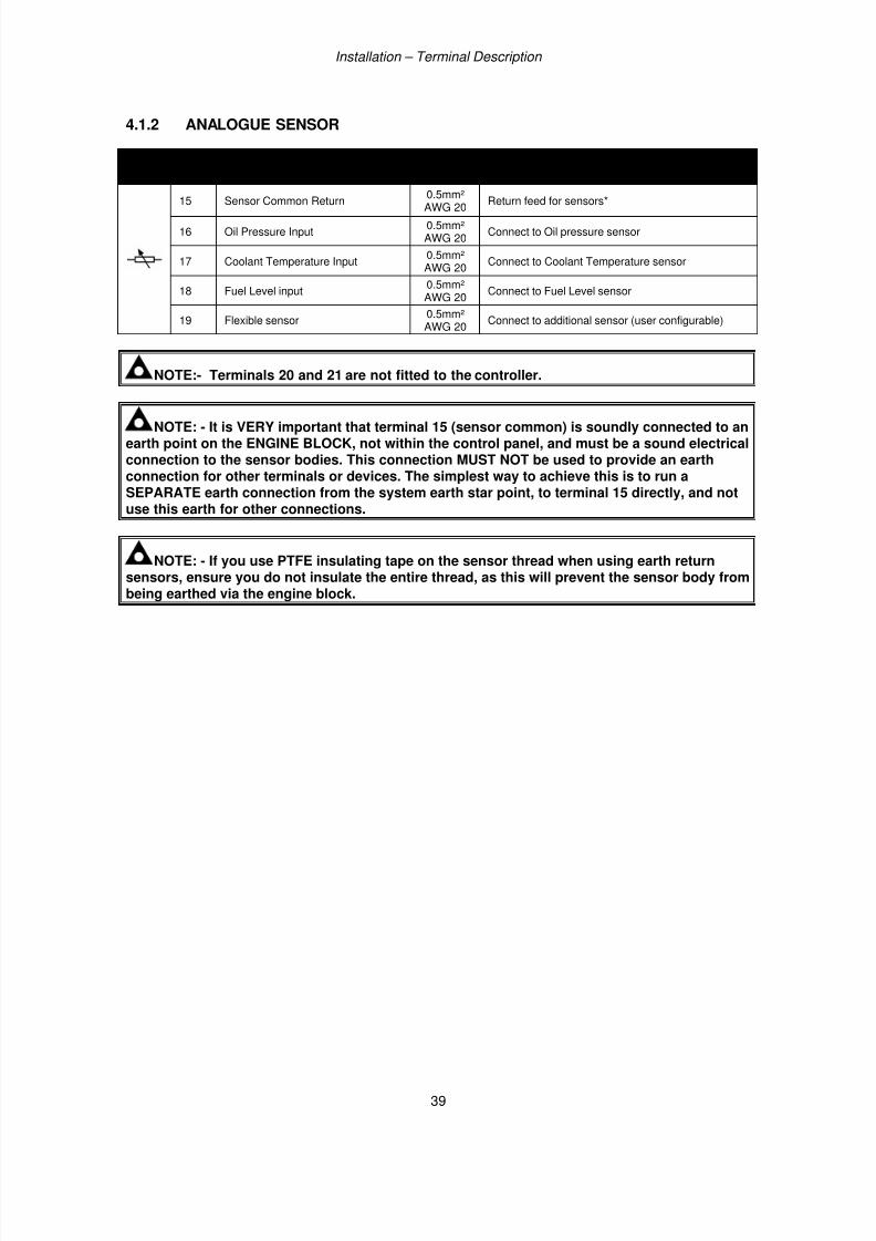
4.1.2 ANALOGUE SENSOR
PINNo
DESCRIPTION CABLESIZE
NOTES
15 Sensor Common Return
0.5mm²
AWG 20 Return feed for sensors*
16 Oil Pressure Input0.5mm²AWG 20
Connect to Oil pressure sensor
17 Coolant Temperature Input0.5mm²AWG 20
Connect to Coolant Temperature sensor
18 Fuel Level input0.5mm²AWG 20
Connect to Fuel Level sensor
19 Flexible sensor0.5mm²AWG 20
Connect to additional sensor (user configurable)
NOTE:- Terminals 20 and 21 are not fitted to the controller.
NOTE: - It is VERY important that terminal 15 (sensor common) is soundly connected to anearth point on the ENGINE BLOCK, not within the control panel, and must be a sound electricalconnection to the sensor bodies. This connection MUST NOT be used to provide an earthconnection for other terminals or devices. The simplest way to achieve this is to run aSEPARATE earth connection from the system earth star point, to terminal 15 directly, and notuse this earth for other connections.
NOTE: - If you use PTFE insulating tape on the sensor thread when using earth returnsensors, ensure you do not insulate the entire thread, as this will prevent the sensor body frombeing earthed via the engine block.
7/14/2019 DEEP SEA 7420
http://slidepdf.com/reader/full/deep-sea-7420-56327e12a4616 40/114
Installation – Terminal Description
40
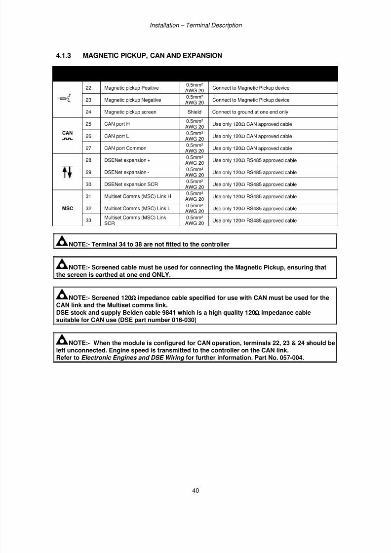
4.1.3 MAGNETIC PICKUP, CAN AND EXPANSION
PINNo
DESCRIPTION CABLESIZE
NOTES
22 Magnetic pickup Positive0.5mm²
AWG 20Connect to Magnetic Pickup device
23 Magnetic pickup Negative0.5mm²AWG 20
Connect to Magnetic Pickup device
24 Magnetic pickup screen Shield Connect to ground at one end only
25 CAN port H0.5mm²AWG 20
Use only 120Ω CAN approved cable
26 CAN port L0.5mm²AWG 20
Use only 120Ω CAN approved cable
27 CAN port Common0.5mm²AWG 20
Use only 120Ω CAN approved cable
28 DSENet expansion +0.5mm²AWG 20
Use only 120Ω RS485 approved cable
29 DSENet expansion -0.5mm²AWG 20
Use only 120Ω RS485 approved cable
30 DSENet expansion SCR 0.5mm²AWG 20 Use only 120Ω RS485 approved cable
MSC
31 Multiset Comms (MSC) Link H0.5mm²AWG 20
Use only 120Ω RS485 approved cable
32 Multiset Comms (MSC) Link L0.5mm²AWG 20
Use only 120Ω RS485 approved cable
33Multiset Comms (MSC) LinkSCR
0.5mm²AWG 20
Use only 120Ω RS485 approved cable
NOTE:- Terminal 34 to 38 are not fitted to the controller
NOTE:- Screened cable must be used for connecting the Magnetic Pickup, ensuring that
the screen is earthed at one end ONLY.
NOTE:- Screened 120ΩΩΩΩ impedance cable specified for use with CAN must be used for theCAN link and the Multiset comms link.
DSE stock and supply Belden cable 9841 which is a high quality 120ΩΩΩΩ impedance cablesuitable for CAN use (DSE part number 016-030)
NOTE:- When the module is configured for CAN operation, terminals 22, 23 & 24 should beleft unconnected. Engine speed is transmitted to the controller on the CAN link.Refer to Electronic Engines and DSE Wiring for further information. Part No. 057-004.
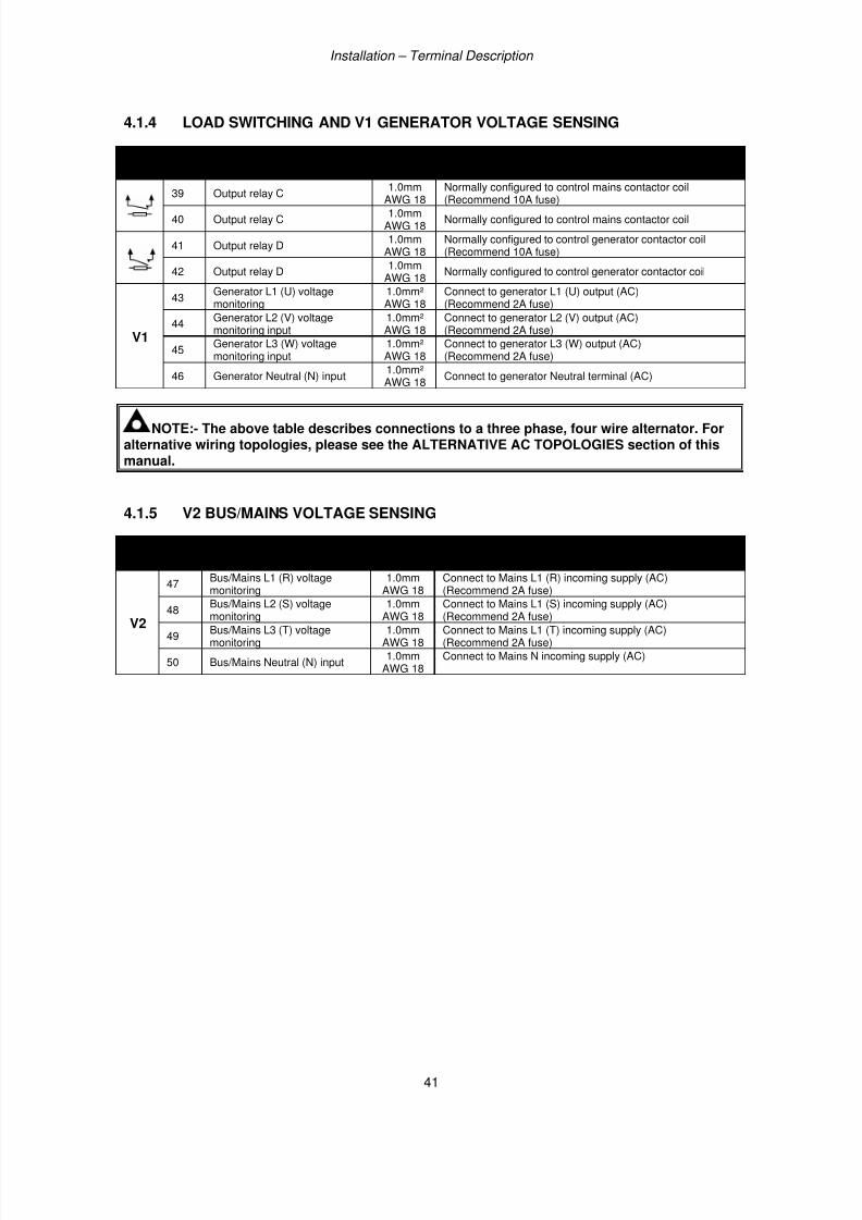
7/14/2019 DEEP SEA 7420
http://slidepdf.com/reader/full/deep-sea-7420-56327e12a4616 41/114
Installation – Terminal Description
41
4.1.4 LOAD SWITCHING AND V1 GENERATOR VOLTAGE SENSING
PINNo
DESCRIPTION CABLESIZE
NOTES
39 Output relay C1.0mm
AWG 18
Normally configured to control mains contactor coil
(Recommend 10A fuse)
40 Output relay C1.0mm
AWG 18Normally configured to control mains contactor coil
41 Output relay D1.0mm
AWG 18Normally configured to control generator contactor coil(Recommend 10A fuse)
42 Output relay D1.0mm
AWG 18Normally configured to control generator contactor coil
V1
43Generator L1 (U) voltagemonitoring
1.0mm²AWG 18
Connect to generator L1 (U) output (AC)(Recommend 2A fuse)
44Generator L2 (V) voltagemonitoring input
1.0mm²AWG 18
Connect to generator L2 (V) output (AC)(Recommend 2A fuse)
45Generator L3 (W) voltagemonitoring input
1.0mm²AWG 18
Connect to generator L3 (W) output (AC)(Recommend 2A fuse)
46 Generator Neutral (N) input1.0mm²AWG 18
Connect to generator Neutral terminal (AC)
NOTE:- The above table describes connections to a three phase, four wire alternator. Foralternative wiring topologies, please see the ALTERNATIVE AC TOPOLOGIES section of thismanual.
4.1.5 V2 BUS/MAINS VOLTAGE SENSING
PINNo
DESCRIPTION CABLESIZE
NOTES
V2
47Bus/Mains L1 (R) voltagemonitoring
1.0mmAWG 18
Connect to Mains L1 (R) incoming supply (AC)(Recommend 2A fuse)
48 Bus/Mains L2 (S) voltagemonitoring
1.0mmAWG 18
Connect to Mains L1 (S) incoming supply (AC)(Recommend 2A fuse)
49Bus/Mains L3 (T) voltagemonitoring
1.0mmAWG 18
Connect to Mains L1 (T) incoming supply (AC)(Recommend 2A fuse)
50 Bus/Mains Neutral (N) input1.0mm
AWG 18Connect to Mains N incoming supply (AC)
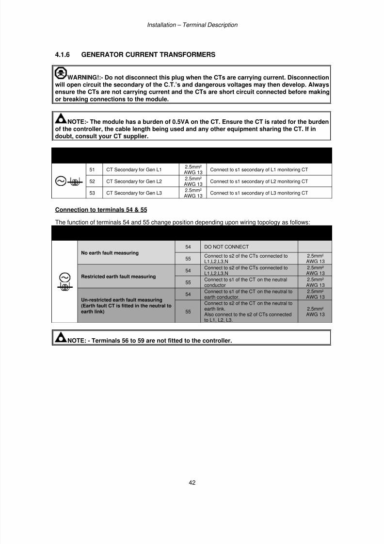
7/14/2019 DEEP SEA 7420
http://slidepdf.com/reader/full/deep-sea-7420-56327e12a4616 42/114
Installation – Terminal Description
42
4.1.6 GENERATOR CURRENT TRANSFORMERS
WARNING!:- Do not disconnect this plug when the CTs are carrying current. Disconnectionwill open circuit the secondary of the C.T.’s and dangerous voltages may then develop. Always
ensure the CTs are not carrying current and the CTs are short circuit connected before makingor breaking connections to the module.
NOTE:- The module has a burden of 0.5VA on the CT. Ensure the CT is rated for the burdenof the controller, the cable length being used and any other equipment sharing the CT. If indoubt, consult your CT supplier.
PINNo
DESCRIPTION CABLESIZE
NOTES
51 CT Secondary for Gen L12.5mm²AWG 13
Connect to s1 secondary of L1 monitoring CT
52 CT Secondary for Gen L2 2.5mm²AWG 13 Connect to s1 secondary of L2 monitoring CT
53 CT Secondary for Gen L32.5mm²AWG 13
Connect to s1 secondary of L3 monitoring CT
Connection to terminals 54 & 55
The function of terminals 54 and 55 change position depending upon wiring topology as follows:
Topology PinNo
Description CABLESIZE
No earth fault measuring
54 DO NOT CONNECT
55Connect to s2 of the CTs connected toL1,L2,L3,N
2.5mm²AWG 13
Restricted earth fault measuring54 Connect to s2 of the CTs connected toL1,L2,L3,N 2.5mm²AWG 13
55Connect to s1 of the CT on the neutralconductor
2.5mm²AWG 13
Un-restricted earth fault measuring(Earth fault CT is fitted in the neutral toearth link)
54Connect to s1 of the CT on the neutral toearth conductor.
2.5mm²AWG 13
55
Connect to s2 of the CT on the neutral toearth link. Also connect to the s2 of CTs connectedto L1, L2, L3.
2.5mm²AWG 13
NOTE: - Terminals 56 to 59 are not fitted to the controller.
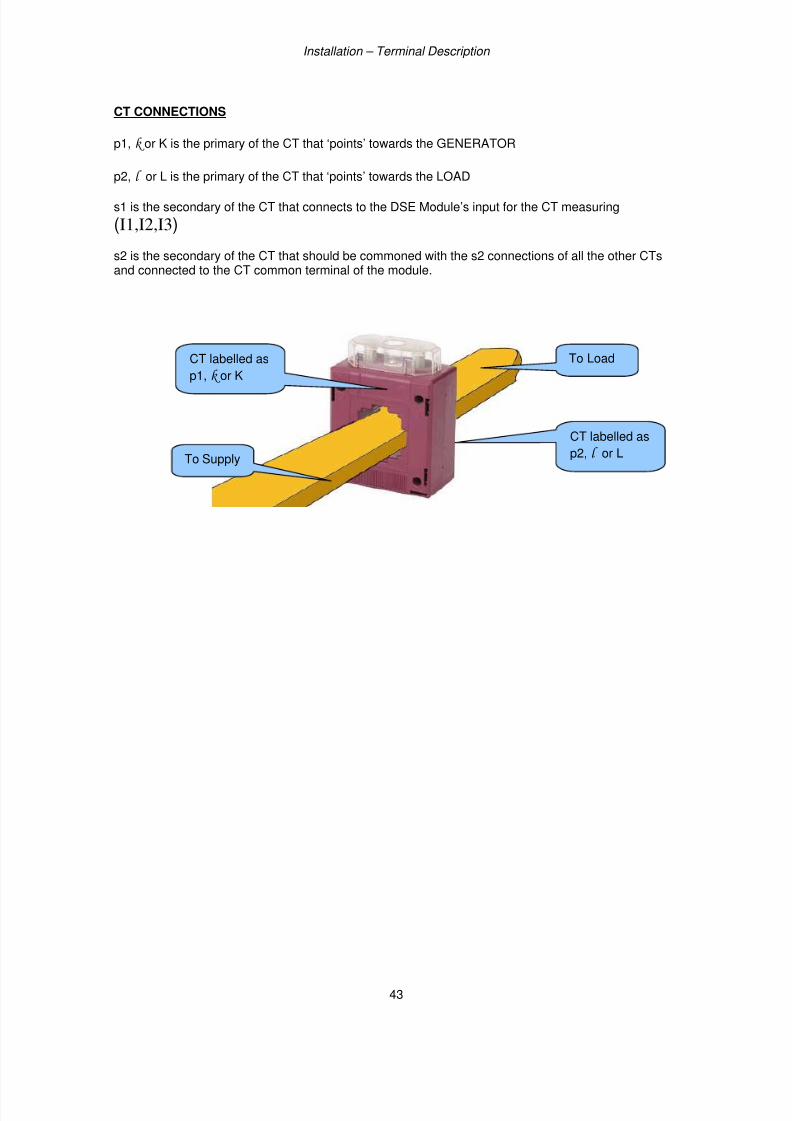
7/14/2019 DEEP SEA 7420
http://slidepdf.com/reader/full/deep-sea-7420-56327e12a4616 43/114
Installation – Terminal Description
43
CT CONNECTIONS
p1, k or K is the primary of the CT that ‘points’ towards the GENERATOR
p2, l or L is the primary of the CT that ‘points’ towards the LOAD
s1 is the secondary of the CT that connects to the DSE Module’s input for the CT measuring
(I1,I2,I3)
s2 is the secondary of the CT that should be commoned with the s2 connections of all the other CTsand connected to the CT common terminal of the module.
CT labelled as
p1, k or K
CT labelled as
p2, l or LTo Supply
To Load
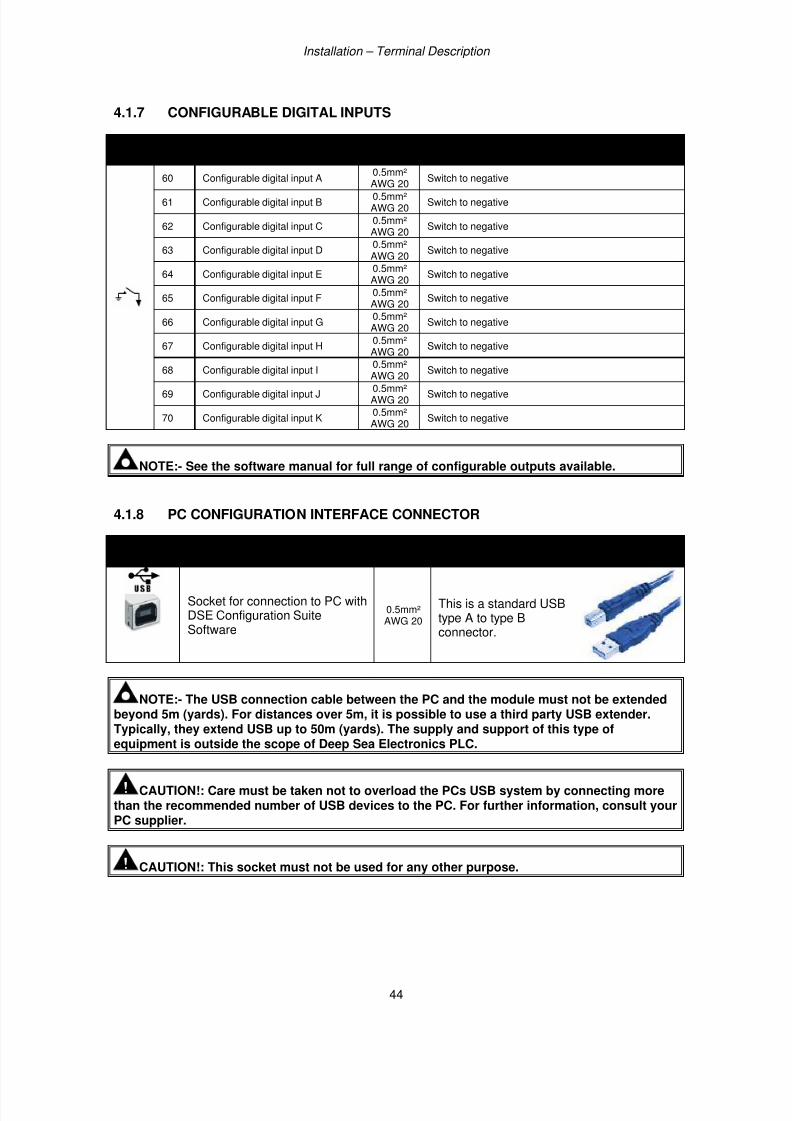
7/14/2019 DEEP SEA 7420
http://slidepdf.com/reader/full/deep-sea-7420-56327e12a4616 44/114
Installation – Terminal Description
44
4.1.7 CONFIGURABLE DIGITAL INPUTS
PINNo
DESCRIPTION CABLESIZE
NOTES
60 Configurable digital input A0.5mm²
AWG 20Switch to negative
61 Configurable digital input B0.5mm²AWG 20
Switch to negative
62 Configurable digital input C0.5mm²AWG 20
Switch to negative
63 Configurable digital input D0.5mm²AWG 20
Switch to negative
64 Configurable digital input E0.5mm²AWG 20
Switch to negative
65 Configurable digital input F0.5mm²AWG 20
Switch to negative
66 Configurable digital input G0.5mm²AWG 20
Switch to negative
67 Configurable digital input H0.5mm²AWG 20
Switch to negative
68 Configurable digital input I0.5mm²AWG 20 Switch to negative
69 Configurable digital input J0.5mm²AWG 20
Switch to negative
70 Configurable digital input K0.5mm²AWG 20
Switch to negative
NOTE:- See the software manual for full range of configurable outputs available.
4.1.8 PC CONFIGURATION INTERFACE CONNECTOR
DESCRIPTION CABLE
SIZE
NOTES
Socket for connection to PC withDSE Configuration SuiteSoftware
0.5mm²AWG 20
This is a standard USBtype A to type Bconnector.
NOTE:- The USB connection cable between the PC and the module must not be extendedbeyond 5m (yards). For distances over 5m, it is possible to use a third party USB extender.Typically, they extend USB up to 50m (yards). The supply and support of this type of
equipment is outside the scope of Deep Sea Electronics PLC.
CAUTION!: Care must be taken not to overload the PCs USB system by connecting morethan the recommended number of USB devices to the PC. For further information, consult yourPC supplier.
CAUTION!: This socket must not be used for any other purpose.
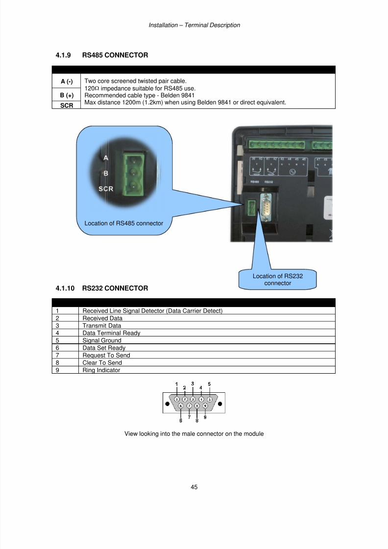
7/14/2019 DEEP SEA 7420
http://slidepdf.com/reader/full/deep-sea-7420-56327e12a4616 45/114
Installation – Terminal Description
45
4.1.9 RS485 CONNECTOR
PIN No NOTES
A (-) Two core screened twisted pair cable.
120Ω
impedance suitable for RS485 use.Recommended cable type - Belden 9841Max distance 1200m (1.2km) when using Belden 9841 or direct equivalent.
B (+)
SCR
4.1.10 RS232 CONNECTOR
PIN No NOTES
1 Received Line Signal Detector (Data Carrier Detect)
2 Received Data
3 Transmit Data4 Data Terminal Ready
5 Signal Ground
6 Data Set Ready
7 Request To Send
8 Clear To Send9 Ring Indicator
View looking into the male connector on the module
Location of RS232connector
Location of RS485 connector

7/14/2019 DEEP SEA 7420
http://slidepdf.com/reader/full/deep-sea-7420-56327e12a4616 46/114
Installation – Typical Wiring Diagrams
46
4.2 TYPICAL WIRING DIAGRAMS
As every system has different requirements, these diagrams show only a TYPICAL system and do notintend to show a complete system.
Genset manufacturers and panel builders may use these diagrams as a starting point; however, youare referred to the completed system diagram provided by your system manufacturer for completewiring detail.
Further wiring suggestions are available in the following DSE publications, available atwww.deepseaplc.com to website members.
DSE PART DESCRIPTION056-022 Breaker Control (Training guide)057-004 Electronic Engines and DSE Wiring
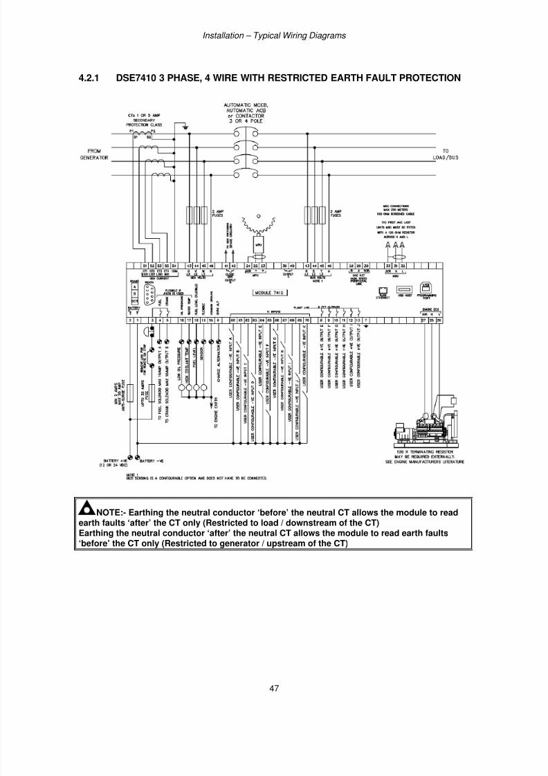
7/14/2019 DEEP SEA 7420
http://slidepdf.com/reader/full/deep-sea-7420-56327e12a4616 47/114
Installation – Typical Wiring Diagrams
47
4.2.1 DSE7410 3 PHASE, 4 WIRE WITH RESTRICTED EARTH FAULT PROTECTION
NOTE:- Earthing the neutral conductor ‘before’ the neutral CT allows the module to readearth faults ‘after’ the CT only (Restricted to load / downstream of the CT)Earthing the neutral conductor ‘after’ the neutral CT allows the module to read earth faults‘before’ the CT only (Restricted to generator / upstream of the CT)
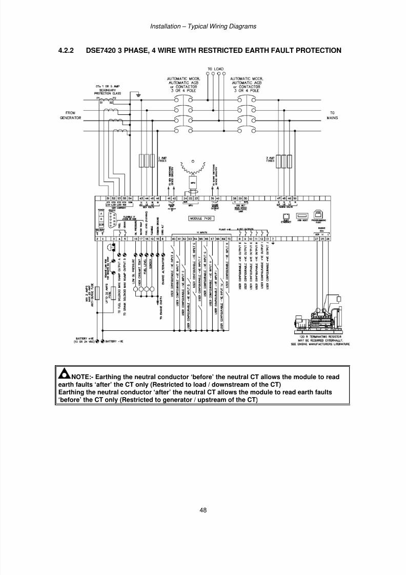
7/14/2019 DEEP SEA 7420
http://slidepdf.com/reader/full/deep-sea-7420-56327e12a4616 48/114
Installation – Typical Wiring Diagrams
48
4.2.2 DSE7420 3 PHASE, 4 WIRE WITH RESTRICTED EARTH FAULT PROTECTION
NOTE:- Earthing the neutral conductor ‘before’ the neutral CT allows the module to readearth faults ‘after’ the CT only (Restricted to load / downstream of the CT)Earthing the neutral conductor ‘after’ the neutral CT allows the module to read earth faults‘before’ the CT only (Restricted to generator / upstream of the CT)
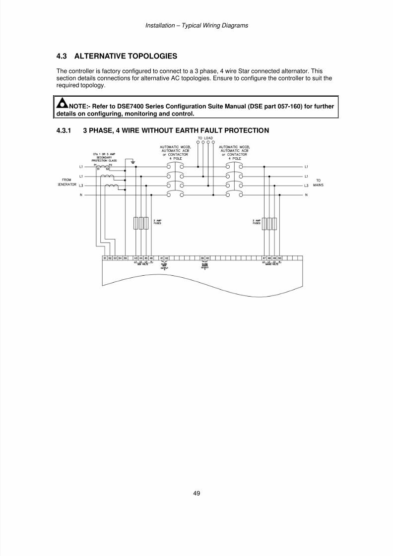
7/14/2019 DEEP SEA 7420
http://slidepdf.com/reader/full/deep-sea-7420-56327e12a4616 49/114
Installation – Typical Wiring Diagrams
49
4.3 ALTERNATIVE TOPOLOGIES
The controller is factory configured to connect to a 3 phase, 4 wire Star connected alternator. Thissection details connections for alternative AC topologies. Ensure to configure the controller to suit therequired topology.
NOTE:- Refer to DSE7400 Series Configuration Suite Manual (DSE part 057-160) for furtherdetails on configuring, monitoring and control.
4.3.1 3 PHASE, 4 WIRE WITHOUT EARTH FAULT PROTECTION
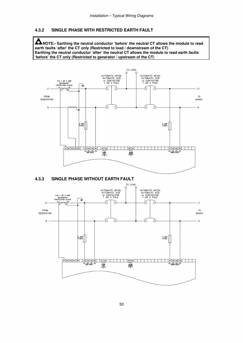
7/14/2019 DEEP SEA 7420
http://slidepdf.com/reader/full/deep-sea-7420-56327e12a4616 50/114
Installation – Typical Wiring Diagrams
50
4.3.2 SINGLE PHASE WITH RESTRICTED EARTH FAULT
NOTE:- Earthing the neutral conductor ‘before’ the neutral CT allows the module to readearth faults ‘after’ the CT only (Restricted to load / downstream of the CT)Earthing the neutral conductor ‘after’ the neutral CT allows the module to read earth faults
‘before’ the CT only (Restricted to generator / upstream of the CT)
4.3.3 SINGLE PHASE WITHOUT EARTH FAULT
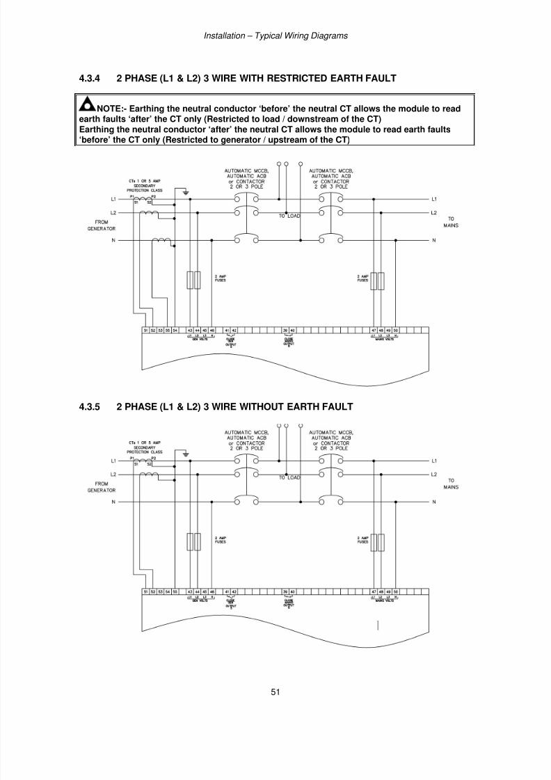
7/14/2019 DEEP SEA 7420
http://slidepdf.com/reader/full/deep-sea-7420-56327e12a4616 51/114
Installation – Typical Wiring Diagrams
51
4.3.4 2 PHASE (L1 & L2) 3 WIRE WITH RESTRICTED EARTH FAULT
NOTE:- Earthing the neutral conductor ‘before’ the neutral CT allows the module to readearth faults ‘after’ the CT only (Restricted to load / downstream of the CT)
Earthing the neutral conductor ‘after’ the neutral CT allows the module to read earth faults‘before’ the CT only (Restricted to generator / upstream of the CT)
4.3.5 2 PHASE (L1 & L2) 3 WIRE WITHOUT EARTH FAULT
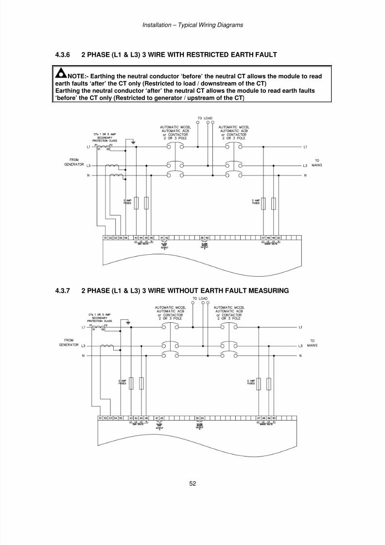
7/14/2019 DEEP SEA 7420
http://slidepdf.com/reader/full/deep-sea-7420-56327e12a4616 52/114
Installation – Typical Wiring Diagrams
52
4.3.6 2 PHASE (L1 & L3) 3 WIRE WITH RESTRICTED EARTH FAULT
NOTE:- Earthing the neutral conductor ‘before’ the neutral CT allows the module to readearth faults ‘after’ the CT only (Restricted to load / downstream of the CT)
Earthing the neutral conductor ‘after’ the neutral CT allows the module to read earth faults‘before’ the CT only (Restricted to generator / upstream of the CT)
4.3.7 2 PHASE (L1 & L3) 3 WIRE WITHOUT EARTH FAULT MEASURING
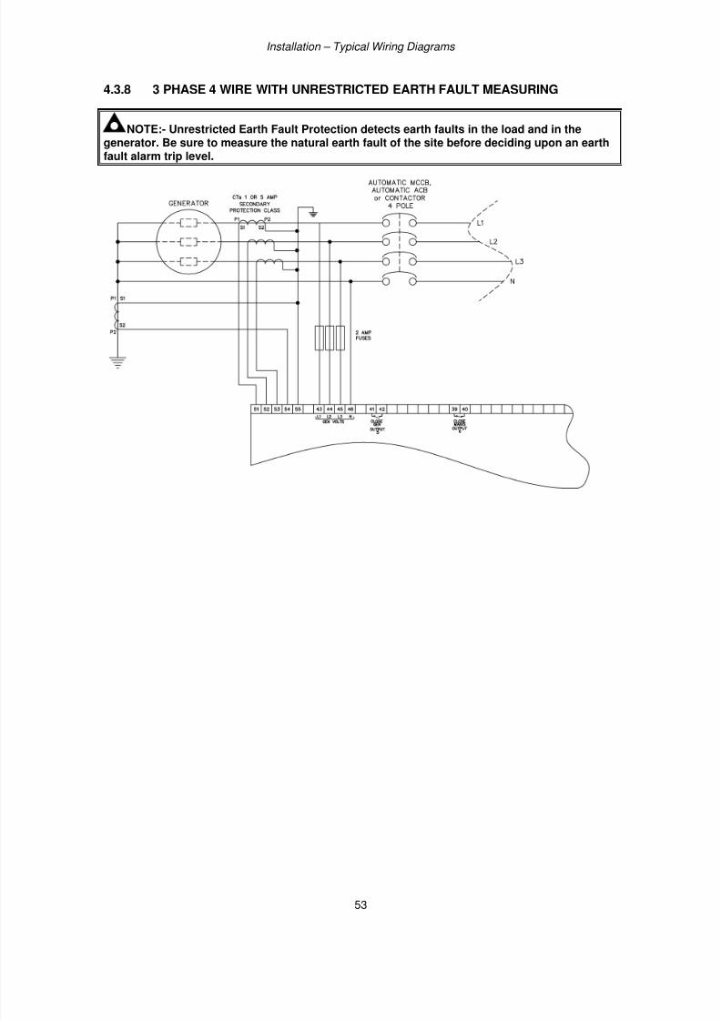
7/14/2019 DEEP SEA 7420
http://slidepdf.com/reader/full/deep-sea-7420-56327e12a4616 53/114
Installation – Typical Wiring Diagrams
53
4.3.8 3 PHASE 4 WIRE WITH UNRESTRICTED EARTH FAULT MEASURING
NOTE:- Unrestricted Earth Fault Protection detects earth faults in the load and in thegenerator. Be sure to measure the natural earth fault of the site before deciding upon an earthfault alarm trip level.
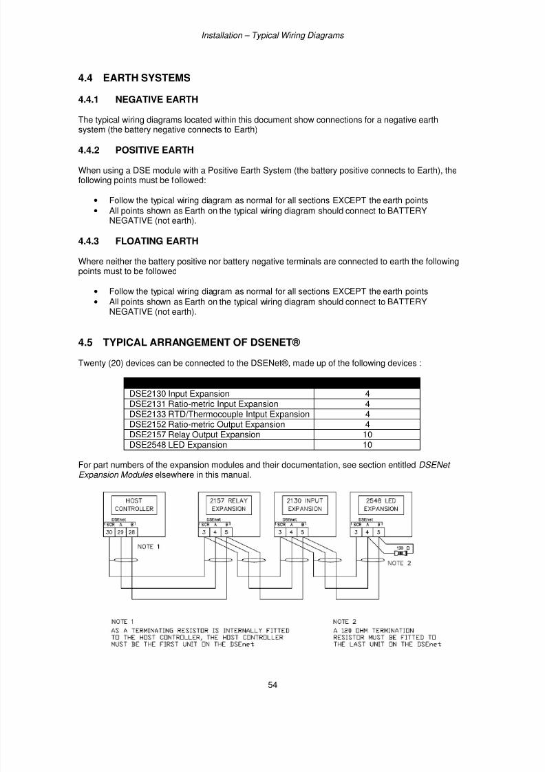
7/14/2019 DEEP SEA 7420
http://slidepdf.com/reader/full/deep-sea-7420-56327e12a4616 54/114
Installation – Typical Wiring Diagrams
54
4.4 EARTH SYSTEMS
4.4.1 NEGATIVE EARTH
The typical wiring diagrams located within this document show connections for a negative earth
system (the battery negative connects to Earth)
4.4.2 POSITIVE EARTH
When using a DSE module with a Positive Earth System (the battery positive connects to Earth), thefollowing points must be followed:
• Follow the typical wiring diagram as normal for all sections EXCEPT the earth points
• All points shown as Earth on the typical wiring diagram should connect to BATTERYNEGATIVE (not earth).
4.4.3 FLOATING EARTH
Where neither the battery positive nor battery negative terminals are connected to earth the followingpoints must to be followed
• Follow the typical wiring diagram as normal for all sections EXCEPT the earth points
• All points shown as Earth on the typical wiring diagram should connect to BATTERYNEGATIVE (not earth).
4.5 TYPICAL ARRANGEMENT OF DSENET®
Twenty (20) devices can be connected to the DSENet®, made up of the following devices :
Device Max Number SupportedDSE2130 Input Expansion 4DSE2131 Ratio-metric Input Expansion 4DSE2133 RTD/Thermocouple Intput Expansion 4DSE2152 Ratio-metric Output Expansion 4DSE2157 Relay Output Expansion 10DSE2548 LED Expansion 10
For part numbers of the expansion modules and their documentation, see section entitled DSENet Expansion Modules elsewhere in this manual.
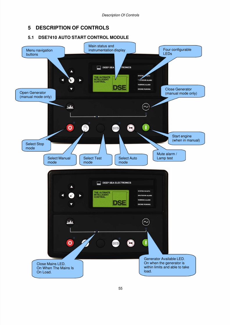
7/14/2019 DEEP SEA 7420
http://slidepdf.com/reader/full/deep-sea-7420-56327e12a4616 55/114
Description Of Controls
55
5 DESCRIPTION OF CONTROLS
5.1 DSE7410 AUTO START CONTROL MODULE
Menu navigation
buttons
Four configurable
LEDs
Select Stopmode
Select Manual
mode
Select Auto
mode
Mute alarm / Lamp test
Start engine(when in manual)
Close Generator(manual mode only)Open Generator
(manual mode only)
Main status andinstrumentation display
Select Test
mode
Close Mains LED.
On When The Mains IsOn Load.
Generator Available LED.On when the generator is
within limits and able to takeload.
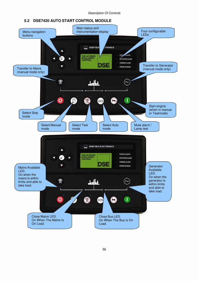
7/14/2019 DEEP SEA 7420
http://slidepdf.com/reader/full/deep-sea-7420-56327e12a4616 56/114
Description Of Controls
56
5.2 DSE7420 AUTO START CONTROL MODULE
Menu navigationbuttons
Four configurableLEDs
Select Stopmode
Select Manualmode
Select Automode
Mute alarm / Lamp test
Start engine(when in manualor Testmode)
Transfer to Generator(manual mode only)Transfer to Mains
(manual mode only)
Main status andinstrumentation display
Select Testmode
Mains AvailableLED.On when themains is withinlimits and able to
take load.
Close Mains LED.On When The Mains IsOn Load.
Close Bus LED.On When The Bus Is OnLoad.
GeneratorAvailableLED.On when thegenerator iswithin limitsand able totake load.
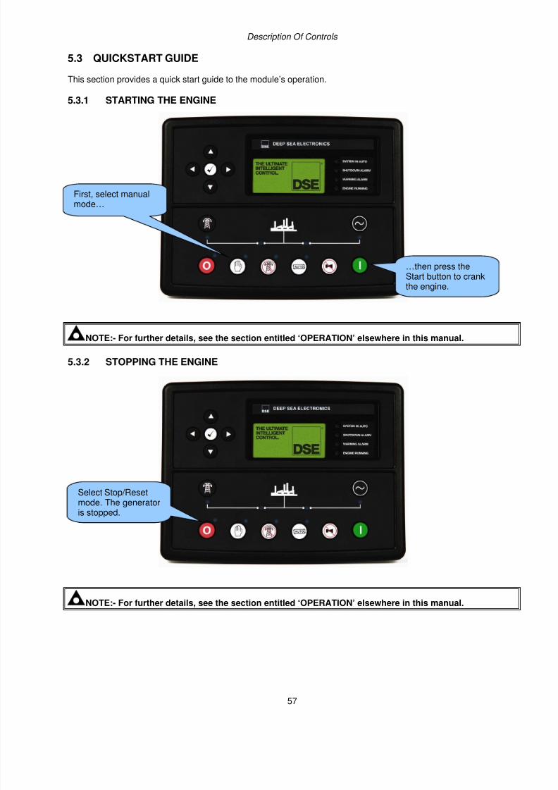
7/14/2019 DEEP SEA 7420
http://slidepdf.com/reader/full/deep-sea-7420-56327e12a4616 57/114
Description Of Controls
57
5.3 QUICKSTART GUIDE
This section provides a quick start guide to the module’s operation.
5.3.1 STARTING THE ENGINE
NOTE:- For further details, see the section entitled ‘OPERATION’ elsewhere in this manual.
5.3.2 STOPPING THE ENGINE
NOTE:- For further details, see the section entitled ‘OPERATION’ elsewhere in this manual.
Select Stop/Resetmode. The generatoris stopped.
First, select manualmode…
…then press theStart button to crankthe engine.
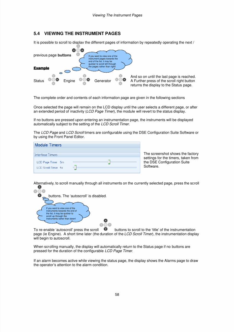
7/14/2019 DEEP SEA 7420
http://slidepdf.com/reader/full/deep-sea-7420-56327e12a4616 58/114
Viewing The Instrument Pages
58
5.4 VIEWING THE INSTRUMENT PAGES
It is possible to scroll to display the different pages of information by repeatedly operating the next /
previous page buttons .
ExampleExampleExampleExample
Status Engine GeneratorAnd so on until the last page is reached.A Further press of the scroll right buttonreturns the display to the Status page.
The complete order and contents of each information page are given in the following sections
Once selected the page will remain on the LCD display until the user selects a different page, or afteran extended period of inactivity (LCD Page Timer ), the module will revert to the status display.
If no buttons are pressed upon entering an instrumentation page, the instruments will be displayedautomatically subject to the setting of the LCD Scroll Timer .
The LCD Page and LCD Scroll timers are configurable using the DSE Configuration Suite Software orby using the Front Panel Editor.
The screenshot shows the factorysettings for the timers, taken fromthe DSE Configuration SuiteSoftware.
Alternatively, to scroll manually through all instruments on the currently selected page, press the scroll
buttons. The ‘autoscroll’ is disabled.
To re-enable ‘autoscroll’ press the scroll buttons to scroll to the ‘title’ of the instrumentationpage (ie Engine). A short time later (the duration of the LCD Scroll Timer ), the instrumentation displaywill begin to autoscroll.
When scrolling manually, the display will automatically return to the Status page if no buttons arepressed for the duration of the configurable LCD Page Timer .
If an alarm becomes active while viewing the status page, the display shows the Alarms page to drawthe operator’s attention to the alarm condition.
If you want to view one of theinstruments towards the end ofthe list, it may be quicker toscroll up through the
instruments rather than down!
If you want to view one of theinstrument pages towards theend of the list, it may bequicker to scroll left throughthe pages rather than right!
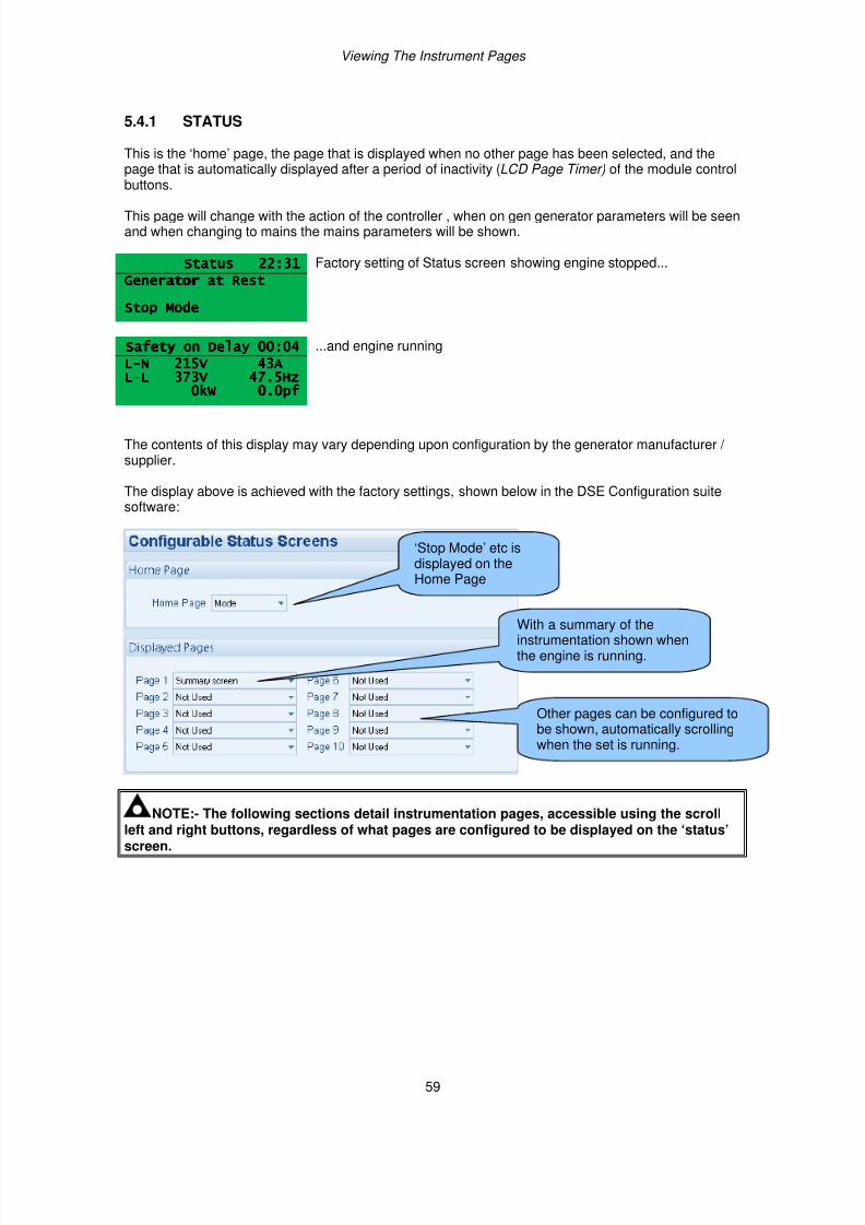
7/14/2019 DEEP SEA 7420
http://slidepdf.com/reader/full/deep-sea-7420-56327e12a4616 59/114
Viewing The Instrument Pages
59
5.4.1 STATUS
This is the ‘home’ page, the page that is displayed when no other page has been selected, and thepage that is automatically displayed after a period of inactivity (LCD Page Timer) of the module controlbuttons.
This page will change with the action of the controller , when on gen generator parameters will be seenand when changing to mains the mains parameters will be shown.
Status 22:31Status 22:31Status 22:31Status 22:31 Factory setting of Status screen showing engine stopped...
Generator at RestGenerator at RestGenerator at RestGenerator at Rest
Stop ModeStop ModeStop ModeStop Mode
Safety on Delay 00:04Safety on Delay 00:04Safety on Delay 00:04Safety on Delay 00:04 ...and engine running
LLLL----N 215V 43AN 215V 43AN 215V 43AN 215V 43ALLLL----L 373V 47.5HzL 373V 47.5HzL 373V 47.5HzL 373V 47.5Hz
0kW 0.0pf0kW 0.0pf0kW 0.0pf0kW 0.0pf
The contents of this display may vary depending upon configuration by the generator manufacturer / supplier.
The display above is achieved with the factory settings, shown below in the DSE Configuration suitesoftware:
NOTE:- The following sections detail instrumentation pages, accessible using the scrollleft and right buttons, regardless of what pages are configured to be displayed on the ‘status’screen.
‘Stop Mode’ etc isdisplayed on theHome Page
With a summary of theinstrumentation shown whenthe engine is running.
Other pages can be configured tobe shown, automatically scrollingwhen the set is running.
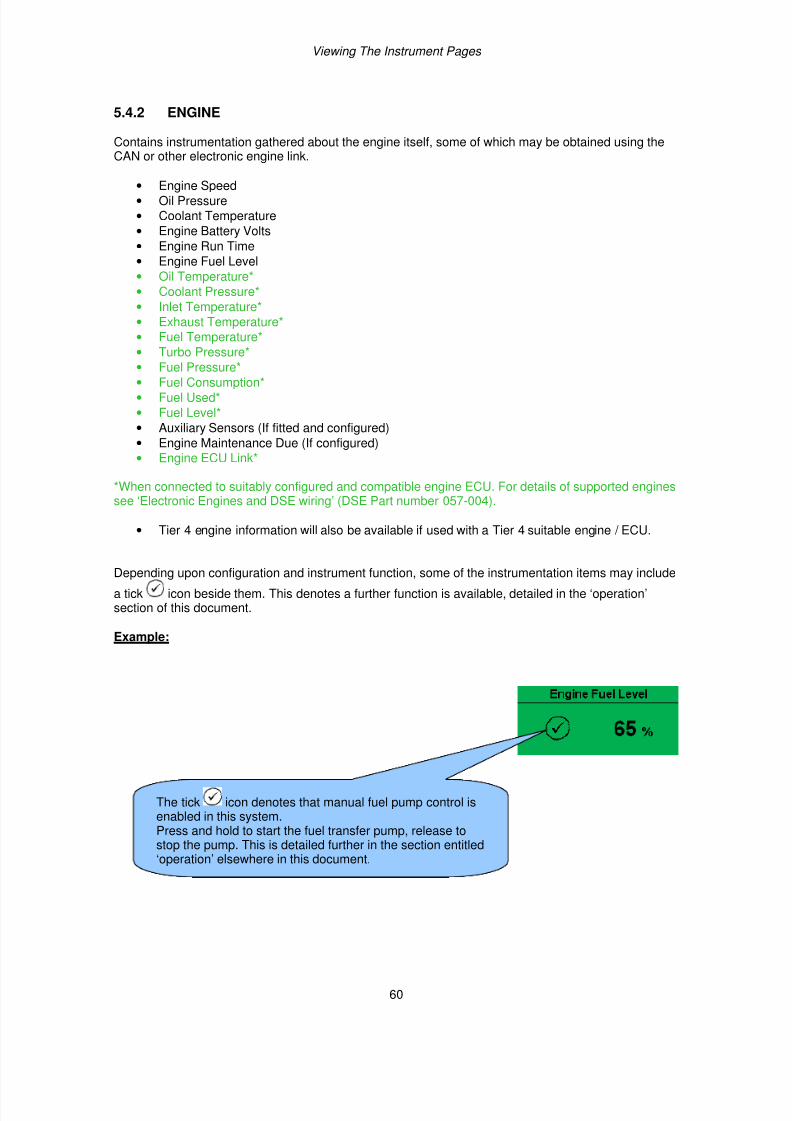
7/14/2019 DEEP SEA 7420
http://slidepdf.com/reader/full/deep-sea-7420-56327e12a4616 60/114
Viewing The Instrument Pages
60
5.4.2 ENGINE
Contains instrumentation gathered about the engine itself, some of which may be obtained using theCAN or other electronic engine link.
• Engine Speed• Oil Pressure
• Coolant Temperature
• Engine Battery Volts
• Engine Run Time
• Engine Fuel Level
• Oil Temperature*
• Coolant Pressure*
• Inlet Temperature*
• Exhaust Temperature*
• Fuel Temperature*
• Turbo Pressure*
• Fuel Pressure*• Fuel Consumption*
• Fuel Used*
• Fuel Level*
• Auxiliary Sensors (If fitted and configured)
• Engine Maintenance Due (If configured)
• Engine ECU Link*
*When connected to suitably configured and compatible engine ECU. For details of supported enginessee ‘Electronic Engines and DSE wiring’ (DSE Part number 057-004).
• Tier 4 engine information will also be available if used with a Tier 4 suitable engine / ECU.
Depending upon configuration and instrument function, some of the instrumentation items may include
a tick icon beside them. This denotes a further function is available, detailed in the ‘operation’section of this document.
Example:
The tick icon denotes that manual fuel pump control isenabled in this system.Press and hold to start the fuel transfer pump, release tostop the pump. This is detailed further in the section entitled‘operation’ elsewhere in this document.

7/14/2019 DEEP SEA 7420
http://slidepdf.com/reader/full/deep-sea-7420-56327e12a4616 61/114
Viewing The Instrument Pages
61
5.4.3 GENERATOR
Contains electrical values of the generator (alternator), measured or derived from the module’s voltageand current inputs.
• Generator Voltage (ph-N)
• Generator Voltage (ph-ph)
• Generator Frequency
• Generator Current
• Generator Earth Current
• Generator Load %
• Generator Load (kW)
• Generator Load (kVA)
• Generator Power Factor
• Generator Power Factor Average
• Generator Load (kVAr)
• Generator Load (kWh, kVAh, kVArh)
• Generator Phase Sequence
• Generator Config (Nominals)
• Generator Active Config
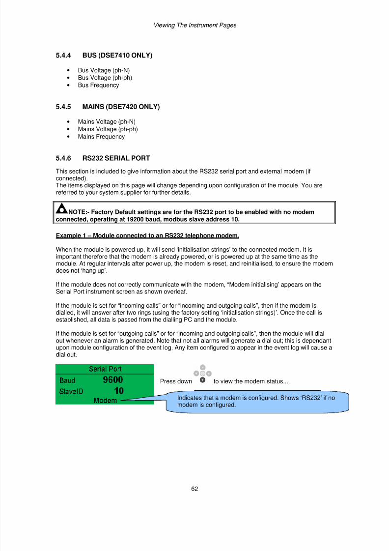
7/14/2019 DEEP SEA 7420
http://slidepdf.com/reader/full/deep-sea-7420-56327e12a4616 62/114
Viewing The Instrument Pages
62
5.4.4 BUS (DSE7410 ONLY)
• Bus Voltage (ph-N)
• Bus Voltage (ph-ph)
• Bus Frequency
5.4.5 MAINS (DSE7420 ONLY)
• Mains Voltage (ph-N)
• Mains Voltage (ph-ph)
• Mains Frequency
5.4.6 RS232 SERIAL PORT
This section is included to give information about the RS232 serial port and external modem (ifconnected).The items displayed on this page will change depending upon configuration of the module. You arereferred to your system supplier for further details.
NOTE:- Factory Default settings are for the RS232 port to be enabled with no modemconnected, operating at 19200 baud, modbus slave address 10.
Example 1 – Module connected to an RS232 telephone modem.
When the module is powered up, it will send ‘initialisation strings’ to the connected modem. It isimportant therefore that the modem is already powered, or is powered up at the same time as themodule. At regular intervals after power up, the modem is reset, and reinitialised, to ensure the modem
does not ‘hang up’.
If the module does not correctly communicate with the modem, “Modem initialising’ appears on theSerial Port instrument screen as shown overleaf.
If the module is set for “incoming calls” or for “incoming and outgoing calls”, then if the modem isdialled, it will answer after two rings (using the factory setting ‘initialisation strings)’. Once the call isestablished, all data is passed from the dialling PC and the module.
If the module is set for “outgoing calls” or for “incoming and outgoing calls”, then the module will dialout whenever an alarm is generated. Note that not all alarms will generate a dial out; this is dependantupon module configuration of the event log. Any item configured to appear in the event log will cause adial out.
Press down to view the modem status....
Indicates that a modem is configured. Shows ‘RS232’ if nomodem is configured.
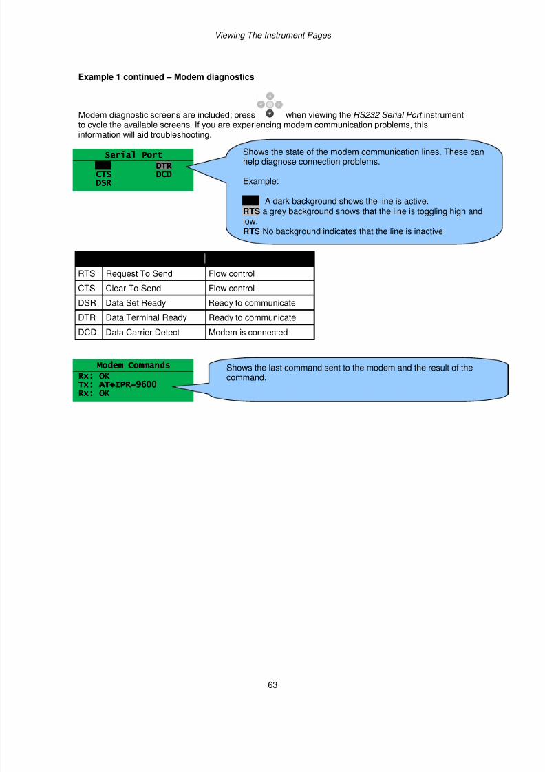
7/14/2019 DEEP SEA 7420
http://slidepdf.com/reader/full/deep-sea-7420-56327e12a4616 63/114
Viewing The Instrument Pages
63
Example 1 continued – Modem diagnostics
Modem diagnostic screens are included; press when viewing the RS232 Serial Port instrument
to cycle the available screens. If you are experiencing modem communication problems, thisinformation will aid troubleshooting.
Serial PortSerial PortSerial PortSerial Port
RTSRTSRTSRTSCTSCTSCTSCTSDSRDSRDSRDSR
DTRDTRDTRDTRDCDDCDDCDDCD
Line Description
RTS Request To Send Flow control
CTS Clear To Send Flow control
DSR Data Set Ready Ready to communicate
DTR Data Terminal Ready Ready to communicate
DCD Data Carrier Detect Modem is connected
Modem CommandsModem CommandsModem CommandsModem Commands
Rx: OKRx: OKRx: OKRx: OK
Tx: AT+IPR=9600Tx: AT+IPR=9600Tx: AT+IPR=9600Tx: AT+IPR=9600Rx: OKRx: OKRx: OKRx: OK
Shows the state of the modem communication lines. These canhelp diagnose connection problems.
Example:
RTS A dark background shows the line is active.RTS a grey background shows that the line is toggling high andlow.RTS No background indicates that the line is inactive
Shows the last command sent to the modem and the result of thecommand.
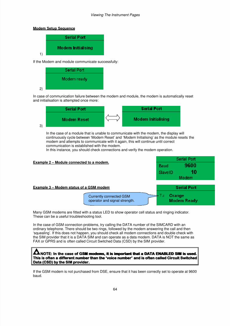
7/14/2019 DEEP SEA 7420
http://slidepdf.com/reader/full/deep-sea-7420-56327e12a4616 64/114
Viewing The Instrument Pages
64
Modem Setup Sequence
1)
If the Modem and module communicate successfully:
2)
In case of communication failure between the modem and module, the modem is automatically resetand initialisation is attempted once more:
3)
In the case of a module that is unable to communicate with the modem, the display willcontinuously cycle between ‘Modem Reset’ and ‘Modem Initialising’ as the module resets themodem and attempts to communicate with it again, this will continue until correctcommunication is established with the modem.In this instance, you should check connections and verify the modem operation.
Example 2 – Module connected to a modem.
Example 3 – Modem status of a GSM modem
Many GSM modems are fitted with a status LED to show operator cell status and ringing indicator.
These can be a useful troubleshooting tool.
In the case of GSM connection problems, try calling the DATA number of the SIMCARD with anordinary telephone. There should be two rings, followed by the modem answering the call and then‘squealing’. If this does not happen, you should check all modem connections and double check withthe SIM provider that it is a DATA SIM and can operate as a data modem. DATA is NOT the same asFAX or GPRS and is often called Circuit Switched Data (CSD) by the SIM provider.
NOTE:NOTE:NOTE:NOTE: In the case of GIn the case of GIn the case of GIn the case of GSM modems, it is important that a DATA ENABLED SIM is used.SM modems, it is important that a DATA ENABLED SIM is used.SM modems, it is important that a DATA ENABLED SIM is used.SM modems, it is important that a DATA ENABLED SIM is used.This is often a different number than the ‘voice number’This is often a different number than the ‘voice number’This is often a different number than the ‘voice number’This is often a different number than the ‘voice number’ and is often called Circuit Switchedand is often called Circuit Switchedand is often called Circuit Switchedand is often called Circuit SwitchedData (CSD) by the SIM providerData (CSD) by the SIM providerData (CSD) by the SIM providerData (CSD) by the SIM provider....
If the GSM modem is not purchased from DSE, ensure that it has been correctly set to operate at 9600baud.
Currently connected GSMoperator and signal strength.
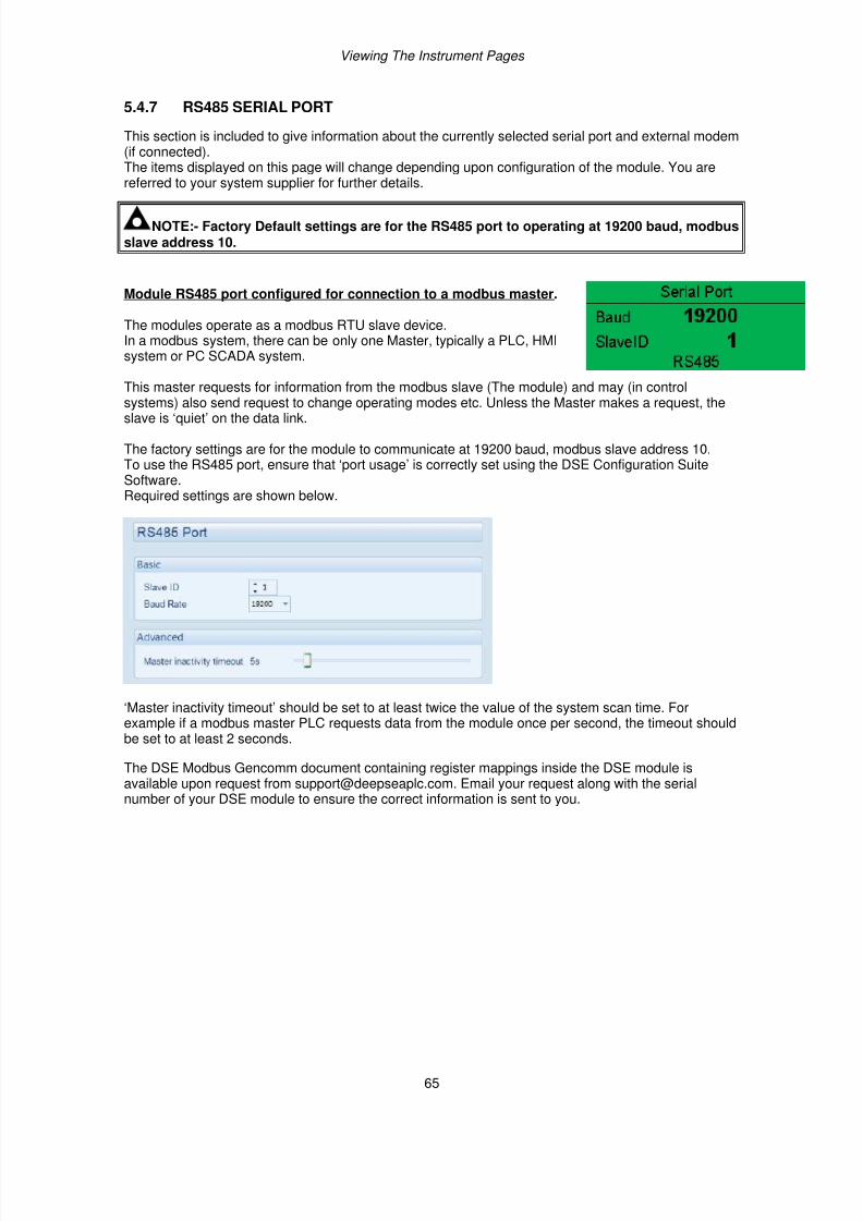
7/14/2019 DEEP SEA 7420
http://slidepdf.com/reader/full/deep-sea-7420-56327e12a4616 65/114
Viewing The Instrument Pages
65
5.4.7 RS485 SERIAL PORT
This section is included to give information about the currently selected serial port and external modem(if connected).The items displayed on this page will change depending upon configuration of the module. You arereferred to your system supplier for further details.
NOTE:- Factory Default settings are for the RS485 port to operating at 19200 baud, modbusslave address 10.
Module RS485 port configured for connection to a modbus master.
The modules operate as a modbus RTU slave device.In a modbus system, there can be only one Master, typically a PLC, HMIsystem or PC SCADA system.
This master requests for information from the modbus slave (The module) and may (in control
systems) also send request to change operating modes etc. Unless the Master makes a request, theslave is ‘quiet’ on the data link.
The factory settings are for the module to communicate at 19200 baud, modbus slave address 10.To use the RS485 port, ensure that ‘port usage’ is correctly set using the DSE Configuration SuiteSoftware.Required settings are shown below.
‘Master inactivity timeout’ should be set to at least twice the value of the system scan time. Forexample if a modbus master PLC requests data from the module once per second, the timeout shouldbe set to at least 2 seconds.
The DSE Modbus Gencomm document containing register mappings inside the DSE module isavailable upon request from [email protected]. Email your request along with the serialnumber of your DSE module to ensure the correct information is sent to you.
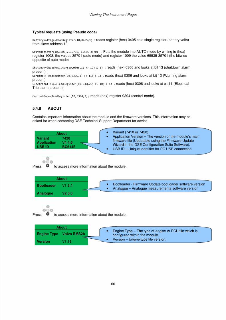
7/14/2019 DEEP SEA 7420
http://slidepdf.com/reader/full/deep-sea-7420-56327e12a4616 66/114
Viewing The Instrument Pages
66
Typical requests (using Pseudo code)
BatteryVoltage=ReadRegister(10,0405,1) : reads register (hex) 0405 as a single register (battery volts)from slave address 10.
WriteRegister(10,1008,2,35701, 65535-35701) : Puts the module into AUTO mode by writing to (hex)register 1008, the values 35701 (auto mode) and register 1009 the value 65535-35701 (the bitwiseopposite of auto mode)
Shutdown=(ReadRegister(10,0306,1) >> 12) & 1) : reads (hex) 0306 and looks at bit 13 (shutdown alarmpresent)Warning=(ReadRegister(10,0306,1) >> 11) & 1) : reads (hex) 0306 and looks at bit 12 (Warning alarmpresent)ElectricalTrip=(ReadRegister(10,0306,1) >> 10) & 1) : reads (hex) 0306 and looks at bit 11 (ElectricalTrip alarm present)
ControlMode=ReadRegister(10,0304,2); reads (hex) register 0304 (control mode).
5.4.8 ABOUT
Contains important information about the module and the firmware versions. This information may beasked for when contacting DSE Technical Support Department for advice.
About
Variant 7420Application V4.4.6USB ID BC614E
Press to access more information about the module.
About
Bootloader V1.3.4
Analogue V2.0.0
Press to access more information about the module.
About
Engine Type Volvo EMS2b
Version V1.18
• Variant (7410 or 7420)
• Application Version – The version of the module’s mainfirmware file (Updatable using the Firmware UpdateWizard in the DSE Configuration Suite Software).
• USB ID – Unique identifier for PC USB connection
• Bootloader - Firmware Update bootloader software version
• Analogue – Analogue measurements software version
• Engine Type – The type of engine or ECU file which isconfigured within the module.
• Version – Engine type file version.
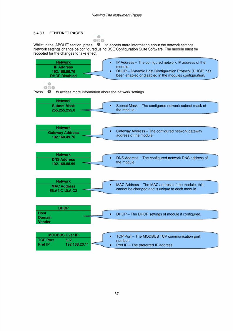
7/14/2019 DEEP SEA 7420
http://slidepdf.com/reader/full/deep-sea-7420-56327e12a4616 67/114
Viewing The Instrument Pages
67
5.4.8.1 ETHERNET PAGES
Whilst in the ‘ABOUT’ section, press to access more information about the network settings.Network settings change be configured using DSE Configuration Suite Software. The module must be
rebooted for the changes to take effect.
Network
IP Address192.168.50.76
DHCP Disabled
Press to access more information about the network settings.
Network
Subnet Mask
255.255.255.0
Network
Gateway Address192.168.49.76
Network
DNS Address
192.168.88.99
Network
MAC AddressE8.A4.C1.0.A.C2
DHCP
Host
DomainVender
MODBUS Over IP
TCP Port 502Pref IP 192.168.20.11
• IP Address – The configured network IP address of themodule
• DHCP – Dynamic Host Configuration Protocol (DHCP) hasbeen enabled or disabled in the modules configuration.
• Subnet Mask – The configured network subnet mask of
the module.
• Gateway Address – The configured network gatewayaddress of the module.
• DNS Address – The configured network DNS address ofthe module.
• MAC Address – The MAC address of the module, thiscannot be changed and is unique to each module.
• DHCP – The DHCP settings of module if configured.
• TCP Port – The MODBUS TCP communication portnumber.
• Pref IP – The preferred IP address.
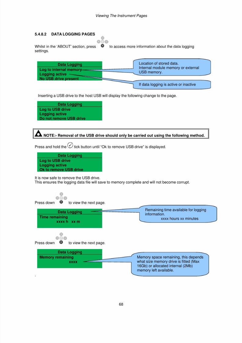
7/14/2019 DEEP SEA 7420
http://slidepdf.com/reader/full/deep-sea-7420-56327e12a4616 68/114
Viewing The Instrument Pages
68
5.4.8.2 DATA LOGGING PAGES
Whilst in the ‘ABOUT’ section, press to access more information about the data loggingsettings.
Data Logging
Log to internal memoryLogging activeNo USB drive present
Inserting a USB drive to the host USB will display the following change to the page.
Data Logging
Log to USB drive
Logging activeDo not remove USB drive
NOTE:- Removal of the USB drive should only be carried out using the following method.
Press and hold the tick button until “Ok to remove USB drive” is displayed.
Data Logging
Log to USB driveLogging active
Ok to remove USB drive
It is now safe to remove the USB drive.This ensures the logging data file will save to memory complete and will not become corrupt.
Press down to view the next page.
Data Logging
Time remainingxxxx h xx m
Press down to view the next page.
Data Logging
Memory remainingxxxx
.
Location of stored data.Internal module memory or externalUSB memory.
If data logging is active or inactive
Remaining time available for logginginformation.
xxxx hours xx minutes
Memory space remaining, this dependswhat size memory drive is fitted (Max16Gb) or allocated internal (2Mb)memory left available.
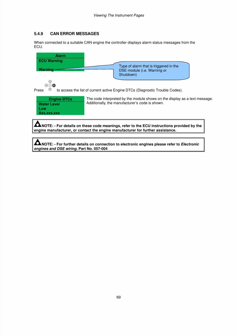
7/14/2019 DEEP SEA 7420
http://slidepdf.com/reader/full/deep-sea-7420-56327e12a4616 69/114
Viewing The Instrument Pages
69
5.4.9 CAN ERROR MESSAGES
When connected to a suitable CAN engine the controller displays alarm status messages from theECU.
AlarmECU Warning
Warning
Press to access the list of current active Engine DTCs (Diagnostic Trouble Codes).
Engine DTCs The code interpreted by the module shows on the display as a text message.Additionally, the manufacturer’s code is shown. Water Level
LowXxx,xxx,xxx
NOTE: - For details on these code meanings, refer to the ECU instructions provided by theengine manufacturer, or contact the engine manufacturer for further assistance.
NOTE: - For further details on connection to electronic engines please refer to Electronic engines and DSE wiring. Part No. 057-004
Type of alarm that is triggered in theDSE module (i.e. Warning orShutdown)
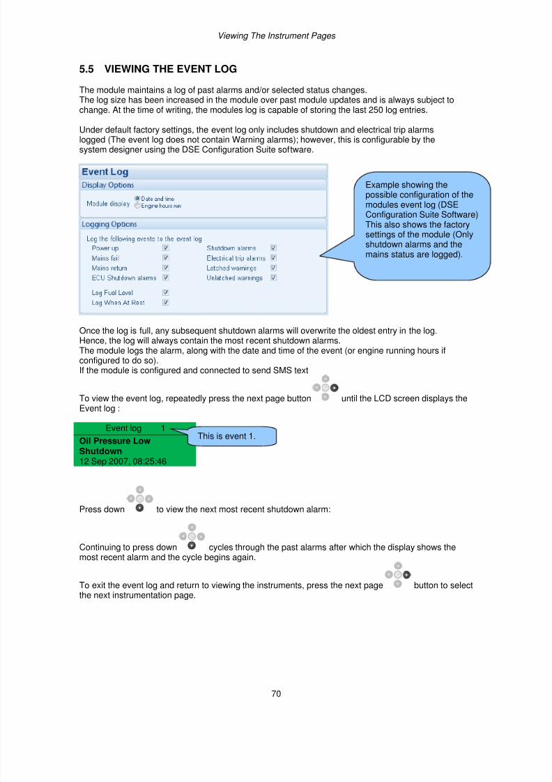
7/14/2019 DEEP SEA 7420
http://slidepdf.com/reader/full/deep-sea-7420-56327e12a4616 70/114
Viewing The Instrument Pages
70
5.5 VIEWING THE EVENT LOG
The module maintains a log of past alarms and/or selected status changes.The log size has been increased in the module over past module updates and is always subject tochange. At the time of writing, the modules log is capable of storing the last 250 log entries.
Under default factory settings, the event log only includes shutdown and electrical trip alarmslogged (The event log does not contain Warning alarms); however, this is configurable by thesystem designer using the DSE Configuration Suite software.
Once the log is full, any subsequent shutdown alarms will overwrite the oldest entry in the log.Hence, the log will always contain the most recent shutdown alarms.The module logs the alarm, along with the date and time of the event (or engine running hours ifconfigured to do so).If the module is configured and connected to send SMS text
To view the event log, repeatedly press the next page button until the LCD screen displays theEvent log :
Event log 1
Oil Pressure LowShutdown12 Sep 2007, 08:25:46
Press down to view the next most recent shutdown alarm:
Continuing to press down cycles through the past alarms after which the display shows themost recent alarm and the cycle begins again.
To exit the event log and return to viewing the instruments, press the next page button to selectthe next instrumentation page.
Example showing thepossible configuration of themodules event log (DSEConfiguration Suite Software)This also shows the factorysettings of the module (Onlyshutdown alarms and the
mains status are logged).
This is event 1.
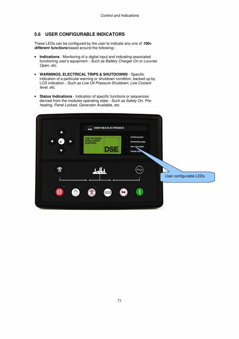
7/14/2019 DEEP SEA 7420
http://slidepdf.com/reader/full/deep-sea-7420-56327e12a4616 71/114
Control and Indications
71
5.6 USER CONFIGURABLE INDICATORS
These LEDs can be configured by the user to indicate any one of 100+ different functions based around the following:-
• Indications - Monitoring of a digital input and indicating associatedfunctioning user’s equipment - Such as Battery Charger On or Louvres Open, etc .
• WARNINGS, ELECTRICAL TRIPS & SHUTDOWNS - Specificindication of a particular warning or shutdown condition, backed up byLCD indication - Such as Low Oil Pressure Shutdown, Low Coolant level, etc.
• Status Indications - Indication of specific functions or sequencesderived from the modules operating state - Such as Safety On, Pre- heating, Panel Locked, Generator Available, etc.
User configurable LEDs
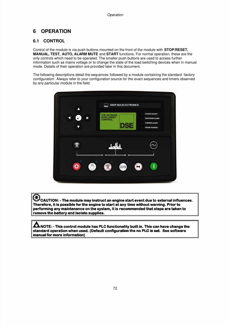
7/14/2019 DEEP SEA 7420
http://slidepdf.com/reader/full/deep-sea-7420-56327e12a4616 72/114
Operation
72
6 OPERATION
6.1 CONTROL
Control of the module is via push buttons mounted on the front of the module with STOP/RESET,
MANUAL, TEST, AUTO, ALARM MUTE and START functions. For normal operation, these are theonly controls which need to be operated. The smaller push buttons are used to access furtherinformation such as mains voltage or to change the state of the load switching devices when in manualmode. Details of their operation are provided later in this document.
The following descriptions detail the sequences followed by a module containing the standard ‘factory configuration ’. Always refer to your configuration source for the exact sequences and timers observedby any particular module in the field.
CAUTION:CAUTION:CAUTION:CAUTION: ---- The module may iThe module may iThe module may iThe module may instruct an engine start event due to external influences.nstruct an engine start event due to external influences.nstruct an engine start event due to external influences.nstruct an engine start event due to external influences.Therefore, it is possible for the engine to start at any time without warning. Prior toTherefore, it is possible for the engine to start at any time without warning. Prior toTherefore, it is possible for the engine to start at any time without warning. Prior toTherefore, it is possible for the engine to start at any time without warning. Prior toperforming any maintenance on the system, it is recommended that steps are taken toperforming any maintenance on the system, it is recommended that steps are taken toperforming any maintenance on the system, it is recommended that steps are taken toperforming any maintenance on the system, it is recommended that steps are taken to
remove the battery and isoremove the battery and isoremove the battery and isoremove the battery and isolate supplies.late supplies.late supplies.late supplies.
NOTE:NOTE:NOTE:NOTE: ---- This controlThis controlThis controlThis control modulemodulemodulemodule has PLC functionality built in.has PLC functionality built in.has PLC functionality built in.has PLC functionality built in. This can have change theThis can have change theThis can have change theThis can have change thestandard operation when used.standard operation when used.standard operation when used.standard operation when used. ((((Default configuration the no PLC is set. See softwareDefault configuration the no PLC is set. See softwareDefault configuration the no PLC is set. See softwareDefault configuration the no PLC is set. See softwaremanual for more information)manual for more information)manual for more information)manual for more information)
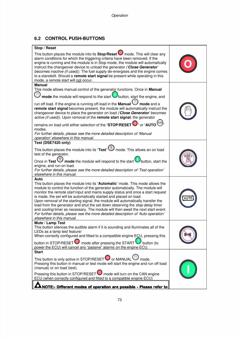
7/14/2019 DEEP SEA 7420
http://slidepdf.com/reader/full/deep-sea-7420-56327e12a4616 73/114
Operation
73
6.2 CONTROL PUSH-BUTTONS
Stop / Reset
This button places the module into its Stop/Reset mode. This will clear anyalarm conditions for which the triggering criteria have been removed. If theengine is running and the module is in Stop mode, the module will automaticallyinstruct the changeover device to unload the generator (‘ Close Generator ’ becomes inactive (if used)). The fuel supply de-energises and the engine comesto a standstill. Should a remote start signal be present while operating in thismode, a remote start will not occur.
Manual This mode allows manual control of the generator functions. Once in Manual
mode the module will respond to the start button, start the engine, and
run off load. If the engine is running off-load in the Manual mode and aremote start signal becomes present, the module will automatically instruct the
changeover device to place the generator on load (‘ Close Generator ’ becomes active (if used)). Upon removal of the remote start signal, the generator
remains on load until either selection of the ‘STOP/RESET ’ or ‘AUTO ’ modes.For further details, please see the more detailed description of ‘Manual operation’ elsewhere in this manual.
Test (DSE7420 only)
This button places the module into its ‘Test’ mode. This allows an on loadtest of the generator.
Once in Test mode the module will respond to the start button, start theengine, and run on load.For further details, please see the more detailed description of ‘Test operation’ elsewhere in this manual.
Auto This button places the module into its ‘Automatic’ mode. This mode allows themodule to control the function of the generator automatically. The module willmonitor the remote start input and mains supply status and once a start requestis made, the set will be automatically started and placed on load.Upon removal of the starting signal, the module will automatically transfer theload from the generator and shut the set down observing the stop delay timerand cooling timer as necessary. The module will then await the next start event.For further details, please see the more detailed description of ‘Auto operation’ elsewhere in this manual.
Mute / Lamp TestThis button silences the audible alarm if it is sounding and illuminates all of theLEDs as a lamp test feature/ When correctly configured and fitted to a compatible engine ECU, pressing this
button in STOP/RESET mode after pressing the START button (topower the ECU) will cancel any “passive” alarms on the engine ECU.
Start
This button is only active in STOP/RESET or MANUAL mode.Pressing this button in manual or test mode will start the engine and run off load(manual) or on load (test).
Pressing this button in STOP/RESET mode will turn on the CAN engine
ECU (when correctly configured and fitted to a compatible engine ECU)
NOTNOTNOTNOTE:E:E:E:---- Different modes of operation are possibleDifferent modes of operation are possibleDifferent modes of operation are possibleDifferent modes of operation are possible ---- Please refer toPlease refer toPlease refer toPlease refer to
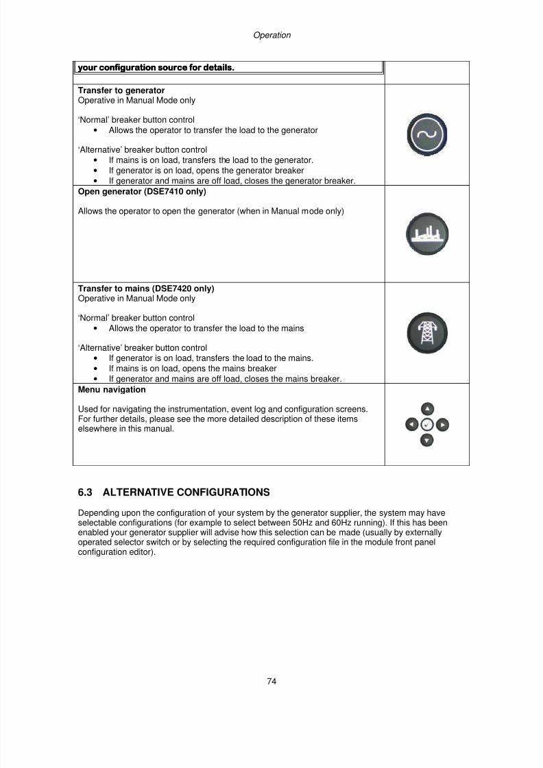
7/14/2019 DEEP SEA 7420
http://slidepdf.com/reader/full/deep-sea-7420-56327e12a4616 74/114
Operation
74
your configuration source for details.your configuration source for details.your configuration source for details.your configuration source for details.
Transfer to generatorOperative in Manual Mode only
‘Normal’ breaker button control
• Allows the operator to transfer the load to the generator
‘Alternative’ breaker button control
• If mains is on load, transfers the load to the generator.
• If generator is on load, opens the generator breaker
• If generator and mains are off load, closes the generator breaker.
Open generator (DSE7410 only)
Allows the operator to open the generator (when in Manual mode only)
Transfer to mains (DSE7420 only)Operative in Manual Mode only
‘Normal’ breaker button control
• Allows the operator to transfer the load to the mains
‘Alternative’ breaker button control
• If generator is on load, transfers the load to the mains.
• If mains is on load, opens the mains breaker
• If generator and mains are off load, closes the mains breaker. Menu navigation
Used for navigating the instrumentation, event log and configuration screens.For further details, please see the more detailed description of these itemselsewhere in this manual.
6.3 ALTERNATIVE CONFIGURATIONS
Depending upon the configuration of your system by the generator supplier, the system may haveselectable configurations (for example to select between 50Hz and 60Hz running). If this has beenenabled your generator supplier will advise how this selection can be made (usually by externallyoperated selector switch or by selecting the required configuration file in the module front panelconfiguration editor).
7/14/2019 DEEP SEA 7420
http://slidepdf.com/reader/full/deep-sea-7420-56327e12a4616 75/114
Operation
75
6.4 DUMMY LOAD / LOAD SHEDDING CONTROL
This feature may be enabled by the system designer to ensure the loading on the generator is kept toa nominal amount. If the load is low, ‘dummy loads’ (typically static load banks) can be introduced toensure the engine is not too lightly loaded. Conversely as the load increases towards the maximum
rating of the set, non-essential loads can be shed to prevent overload of the generator.
6.2.1 DUMMY LOAD CONTROL
The dummy load control feature (if enabled) allows for a maximum of five dummy load steps.When the set is first started, all configured Dummy Load Control outputs are de-energised.Once the generator is placed onto load, the generator loading is monitored by the Dummy Load Control scheme.
If the generator loading falls below the Dummy Load Control Trip setting (kW), the Dummy Load Control Trip Delay is displayed on the module display. If the generator loading remains at this low levelfor the duration of the timer, the first Dummy Load Control output is energised. This is used to energise
external circuits to switch in (for instance) a static load bank.
The generator loading has now been increased by the first dummy load. Again the generator loading ismonitored. This continues until all configured Dummy Load Control outputs are energised.Should the generator loading rise above the Dummy Load Return level, the Dummy Load Return Delay begins. If the loading remains at these levels after the completion of the timer, the ‘highest’ activeDummy Load Control output is de-energised. This continues until all Dummy Load Control outputshave been de-energised.
6.2.2 LOAD SHEDDING CONTROL
The Load Shedding Control feature (if enabled) allows for a maximum of five load shedding steps.When the generator is about to take load, the configured number of Load Shedding Control Outputs at
Startup will energise. This configurable setting allows (for instance) certain loads to be removed fromthe generator prior to the set’s load switch being closed. This can be used to ensure the initial loadingof the set is kept to a minimum, below the Load Acceptance specification of the generating set.
The generator is then placed on load. The Load Shedding Control scheme begins.When the load reaches the Load Shedding Trip level the Trip Delay timer will start. If the generatorloading is still high when the timer expires, the first Load shedding Control output will energise. Whenthe load has been above the trip level for the duration of the timer the ‘next’ Load shedding Control output will energise and so on until all Load Shedding Control outputs are energised.
If at any time the load falls back below the Load Shedding Return level, the Return Time will start. Ifthe load remains below the return level when the timer has expired the ‘highest’ Load Shedding Control output that has been energised will be de-energised. This process will continue until all outputs
have been de-energised.When the set enters a stopping sequence for any reason the Load Shedding control ’ outputs will de-energise at the same time as the generator load switch is signalled to open.
NOTE:- Refer to DSE7400 Series Configuration Suite Manual (DSE part 057-160) for furtherdetails on configuration.
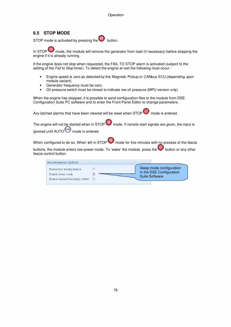
7/14/2019 DEEP SEA 7420
http://slidepdf.com/reader/full/deep-sea-7420-56327e12a4616 76/114
Operation
76
6.5 STOP MODE
STOP mode is activated by pressing the button.
In STOP mode, the module will remove the generator from load (if necessary) before stopping theengine if it is already running.
If the engine does not stop when requested, the FAIL TO STOP alarm is activated (subject to thesetting of the Fail to Stop timer). To detect the engine at rest the following must occur :
• Engine speed is zero as detected by the Magnetic Pickup or CANbus ECU (depending uponmodule variant).
• Generator frequency must be zero.
• Oil pressure switch must be closed to indicate low oil pressure (MPU version only)
When the engine has stopped, it is possible to send configuration files to the module from DSEConfiguration Suite PC software and to enter the Front Panel Editor to change parameters.
Any latched alarms that have been cleared will be reset when STOP mode is entered.
The engine will not be started when in STOP mode. If remote start signals are given, the input is
ignored until AUTO mode is entered.
When configured to do so, When left in STOP mode for five minutes with no presses of the fascia
buttons, the module enters low power mode. To ‘wake’ the module, press the button or any otherfascia control button.
Sleep mode configurationin the DSE ConfigurationSuite Software
7/14/2019 DEEP SEA 7420
http://slidepdf.com/reader/full/deep-sea-7420-56327e12a4616 77/114
Operation
77
6.5.1 ECU OVERRIDE
NOTE:- ECU Override function is only applicable when the controller is configured for aCAN engine.
NOTE:- Depending upon system design, the ECU may be powered or unpowered when themodule is in STOP mode. ECU override is only applicable if the ECU is unpowered when inSTOP mode.
When the ECU powered down (as is normal when in STOP mode), it is not possible to read thediagnostic trouble codes or instrumentation. Additionally, it is not possible to use the enginemanufacturers’ configuration tools.
As the ECU is usually unpowered when the engine is not running, it must be turned on manually asfollows :
• Select STOP mode on the DSE controller.
• Press and hold the START button to power the ECU. As the controller is in STOP mode,the engine will not be started.
.
• The ECU will remain powered 2 minutes after the START button is released.
This is also useful if the engine manufacturer’s tools need to be connected to the engine, for instanceto configure the engine as the ECU needs to be powered up to perform this operation.
7/14/2019 DEEP SEA 7420
http://slidepdf.com/reader/full/deep-sea-7420-56327e12a4616 78/114
Operation
78
6.6 MANUAL MODE
NOTE:- If a digital input configured to panel lock is active, changing module modes willnot be possible. Viewing the instruments and event logs is NOT affected by panel lock.
Activate Manual mode be pressing the pushbutton. An LED indicator beside the button confirmsthis action.
Manual mode allows the operator to start and stop the set manually, and if required change the stateof the load switching devices.
6.6.1 WAITING IN MANUAL MODE
When in manual mode, the set will not start automatically.
To begin the starting sequence, press the button.
6.6.2 STARTING SEQUENCE
NOTE:- There is no start delay in this mode of operation.
The fuel relay is energised and the engine is cranked.
NOTE:- If the unit has been configured for CAN, compatible ECU’s will receive the startcommand via CAN.
If the engine fails to fire during this cranking attempt then the starter motor is disengaged for the crank rest duration after which the next start attempt is made. Should this sequence continue beyond the set
number of attempts, the start sequence will be terminated and the display shows Fail to Start.
When the engine fires, the starter motor is disengaged. Speed detection is factory configured to bederived from the main alternator output frequency but can additionally be measured from a MagneticPickup mounted on the flywheel (Selected by the configuration software).
Additionally, rising oil pressure can be used disconnect the starter motor (but cannot detectunderspeed or overspeed).
NOTE:- If the unit has been configured for CAN, speed sensing is via CAN.
After the starter motor has disengaged, the Safety On timer activates, allowing Oil Pressure, High
Engine Temperature, Under-speed, Charge Fail and any delayed Auxiliary fault inputs to stabilisewithout triggering the fault.
7/14/2019 DEEP SEA 7420
http://slidepdf.com/reader/full/deep-sea-7420-56327e12a4616 79/114
Operation
79
6.6.3 ENGINE RUNNING
In manual mode, the load is not transferred to the generator unless a ‘loading request’ is made.A loading request can come from a number of sources.
•Pressing the transfer to generator button
• Mains supply out of limits (DSE7420 only)
• Activation of an auxiliary input that has been configured to remote start on load
• Activation of the inbuilt exercise scheduler if configured for ‘on load’ runs.
NOTE:-The load transfer signal remains inactive until the Oil Pressure has risen. Thisprevents excessive wear on the engine.
Once the load has been transferred to the generator, it will not be automatically transferred back to themains supply. To manually transfer the load back to the mains either:
• Press the Transfer to Mains button (DSE7420 only)
• Press the Open Generator button (DSE7410 only)
• Press the Auto Mode button to return to automatic mode.
For further details of breaker control, see the section entitled “controls and indications” elsewhere inthis manual.
6.6.4 MANUAL FUEL PUMP CONTROL
• Navigate to the instruments page using the buttons and locate FUEL LEVEL. is
shown on the module display to indicate that this feature is available.• Press and hold the button to energise the transfer pump. The pump starts two seconds
after the button is pressed.
• Release the button to de-energise the transfer pump.
6.6.5 MANUAL SPEED CONTROL
• Navigate to the instruments page using the buttons and locate ENGINE SPEED. isshown on the module display to indicate that this feature is available.
• Press the button to enter edit mode
• Press (up or down) to change the engine speed.
• Press the button again to exit the editor and leave the engine running at the newly selectedspeed.
7/14/2019 DEEP SEA 7420
http://slidepdf.com/reader/full/deep-sea-7420-56327e12a4616 80/114
Operation
80
6.6.6 STOPPING SEQUENCE
In manual mode the set will continue to run until either :
•The stop button is pressed – The set will immediately stop
• The auto button is pressed. The set will observe all auto mode start requests and stoppingtimers before beginning the Auto mode stopping sequence .
6.7 TEST MODE
NOTE:- Test Mode is only applicable to DSE7420 controller.
NOTE:- If a digital input configured to panel lock is active, changing module modes will
not be possible. Viewing the instruments and event logs is NOT affected by panel lock.
Activate test mode be pressing the pushbutton. An LED indicator beside the button confirms thisaction.
Test mode will start the set and transfer the load to the generator to provide a Test on load function.
6.7.1 WAITING IN TEST MODE
When in test mode, the set will not start automatically.
To begin the starting sequence, press the button.
6.7.2 STARTING SEQUENCE
The set begins to crank.
NOTE:- If the unit has been configured for CAN, compatible ECU’s will receive the startcommand via CAN.
If the engine fails to fire during this cranking attempt then the starter motor is disengaged for the crank rest duration after which the next start attempt is made. Should this sequence continue beyond the setnumber of attempts, the start sequence will be terminated and the display shows Fail to Start.
When the engine fires, the starter motor is disengaged. Speed detection is factory configured to be
derived from the main alternator output frequency but can additionally be measured from a MagneticPickup mounted on the flywheel (Selected by PC using the configuration software).
Additionally, rising oil pressure can be used disconnect the starter motor (but cannot detectunderspeed or overspeed).
NOTE:- If the unit has been configured for CAN, speed sensing is via CAN.
After the starter motor has disengaged, the Safety On timer activates, allowing Oil Pressure, HighEngine Temperature, Under-speed, Charge Fail and any delayed Auxiliary fault inputs to stabilisewithout triggering the fault.
7/14/2019 DEEP SEA 7420
http://slidepdf.com/reader/full/deep-sea-7420-56327e12a4616 81/114
Operation
81
6.7.3 ENGINE RUNNING
Once the engine is running, the Warm Up timer, if selected, begins, allowing the engine to stabilisebefore accepting the load.
Load will be automatically transferred from the mains supply to the generator.
NOTE:-The load transfer signal remains inactive until the Oil Pressure has risen. Thisprevents excessive wear on the engine.
In test mode, the set will continue to run on load until either:
• The stop button is pressed – The set will immediately stop
• The auto button is pressed. The set will observe all auto mode start requests and stoppingtimers before beginning the Auto mode stopping sequence .
7/14/2019 DEEP SEA 7420
http://slidepdf.com/reader/full/deep-sea-7420-56327e12a4616 82/114
Operation
82
6.8 AUTOMATIC MODE
NOTE:- If a digital input configured to panel lock is active, changing module modes willnot be possible. Viewing the instruments and event logs is NOT affected by panel lock.
Activate auto mode be pressing the pushbutton. An LED indicator beside the button confirms thisaction.
Auto mode will allow the generator to operate fully automatically, starting and stopping as required withno user intervention.
6.8.1 WAITING IN AUTO MODE
If a starting request is made, the starting sequence will begin.Starting requests can be from the following sources:
• Mains supply out of limits (DSE7420 only)
• Activation of an auxiliary input that has been configured to remote start on load or remote start off load.
• Activation of the inbuilt exercise scheduler.
• Instruction from external remote telemetry devices using the RS232 or RS485 interface
6.8.2 STARTING SEQUENCE
To allow for ‘false’ start requests such as mains brownouts, the start delay timer begins. There areindividual start delay timers for each of the different start request types.
Should all start requests be removed during the start delay timer, the unit will return to a stand-bystate.
If a start request is still present at the end of the start delay timer, the fuel relay is energised and theengine will be cranked.
NOTE:- If the unit has been configured for CAN, compatible ECU’s will receive the startcommand via CAN.
If the engine fails to fire during this cranking attempt then the starter motor is disengaged for the crank rest duration after which the next start attempt begins. Should this sequence continue beyond the setnumber of attempts, the start sequence will be terminated and the display shows Fail to Start.
The starter motor is disengaged when the engine fires. Speed detection is factory configured to be
derived from the main alternator output frequency, but can additionally be measured from a MagneticPickup mounted on the flywheel (Selected by PC using the configuration software).
Additionally, rising oil pressure can be used to disconnect the starter motor (but cannot detectunderspeed or overspeed).
NOTE:- If the unit has been configured for CAN, speed sensing is via CAN.
After the starter motor has disengaged, the Safety On timer activates, allowing Oil Pressure, HighEngine Temperature, Under-speed, Charge Fail and any delayed Auxiliary fault inputs to stabilisewithout triggering the fault.
7/14/2019 DEEP SEA 7420
http://slidepdf.com/reader/full/deep-sea-7420-56327e12a4616 83/114
Operation
83
6.8.3 ENGINE RUNNING
Once the engine is running, the Warm Up timer, if selected, begins, allowing the engine to stabilisebefore accepting the load.
DSE7410 - The generator will be placed on load.
DSE7420 - Load will be transferred from the mains supply to the generator
NOTE:-The load transfer signal remains inactive until the Oil Pressure has risen. Thisprevents excessive wear on the engine.
As the load increases and decreases, the module may (depending upon configuration) add dummyloads or remove non-essential loads. This is configured as part of the Load Shedding and Dummy Load control settings in the DSE Configuration Suite Software.See section entitled Dummy Load / Load Shedding elsewhere in this document for further details.
If all start requests are removed, the stopping sequence will begin.
6.8.4 STOPPING SEQUENCE
The return delay timer operates to ensure that the starting request has been permanently removedand isn’t just a short term removal. Should another start request be made during the cooling downperiod, the set will return on load.
If there are no starting requests at the end of the return delay timer, the load is transferred back fromthe generator to the mains supply and the cooling timer is initiated.
The cooling timer allows the set to run off load and cool sufficiently before being stopped. This isparticularly important where turbo chargers are fitted to the engine.
After the cooling timer has expired, the set is stopped.
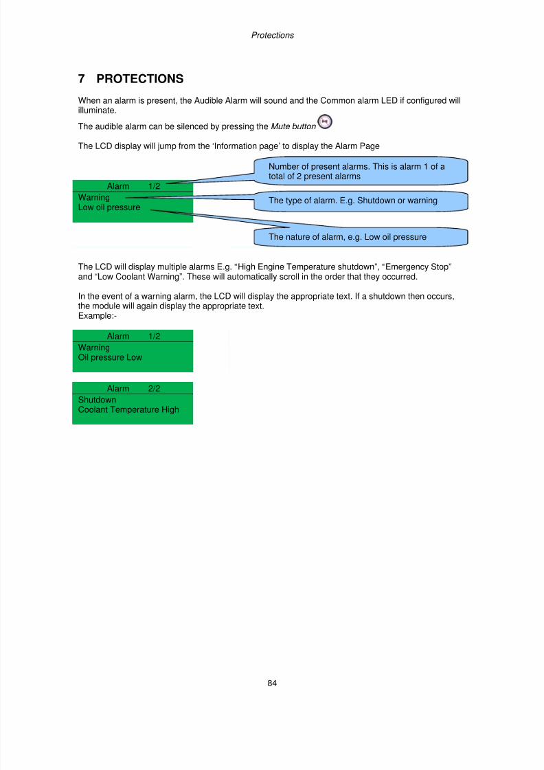
7/14/2019 DEEP SEA 7420
http://slidepdf.com/reader/full/deep-sea-7420-56327e12a4616 84/114
Protections
84
7 PROTECTIONS
When an alarm is present, the Audible Alarm will sound and the Common alarm LED if configured willilluminate.
The audible alarm can be silenced by pressing the Mute button
The LCD display will jump from the ‘Information page’ to display the Alarm Page
Alarm 1/2
WarningLow oil pressure
The LCD will display multiple alarms E.g. “High Engine Temperature shutdown”, “Emergency Stop”and “Low Coolant Warning”. These will automatically scroll in the order that they occurred.
In the event of a warning alarm, the LCD will display the appropriate text. If a shutdown then occurs,the module will again display the appropriate text.Example:-
Alarm 1/2
WarningOil pressure Low
Alarm 2/2
ShutdownCoolant Temperature High
The type of alarm. E.g. Shutdown or warning
The nature of alarm, e.g. Low oil pressure
Number of present alarms. This is alarm 1 of atotal of 2 present alarms
7/14/2019 DEEP SEA 7420
http://slidepdf.com/reader/full/deep-sea-7420-56327e12a4616 85/114
Protections
85
7.1 PROTECTIONS DISABLED
User configuration is possible to prevent Shutdown / Electrical Trip alarms from stopping the engine.Under such conditions, Protections Disabled will appear on the module display to inform the operatorof this status.
This feature is provided to assist the system designer in meeting specifications for “Warning only”,“Protections Disabled”, “Run to Destruction”, “War mode” or other similar wording.
When configuring this feature in the PC software, the system designer chooses to make the featureeither permanently active, or only active upon operation of an external switch. The system designerprovides this switch (not DSE) so its location will vary depending upon manufacturer, however itnormally takes the form of a key operated switch to prevent inadvertent activation. Depending uponconfiguration, a warning alarm may be generated when the switch is operated.
The feature is configurable in the PC configuration software for the module. Writing a configuration tothe controller that has “Protections Disabled” configured, results in a warning message appearing onthe PC screen for the user to acknowledge before the controller’s configuration is changed. This
prevents inadvertent activation of the feature.
7.1.1 INDICATION / WARNING ALARMS
Under Indication or Warning alarms:
• The module operation is unaffected by the Protections Disabled feature. See sections entitledIndications and Warnings elsewhere in this document.
7.1.2 SHUTDOWN / ELECTRICAL TRIP ALARMS
NOTE:- The EMERGENCY STOP input and shutdown alarm continues to operate evenwhen Protections Disabled has been activated.
Under Shutdown or Electrical Trip alarm conditions (excluding Emergency Stop):
• The alarm is displayed on the screen as detailed in the section entitled Shutdown alarm selsewhere in this document.
• The set continues to run.
• The load switch maintains its current position (it is not opened if already closed)
• Shutdown Blocked also appears on the LCD screen to inform the operator that theProtections Disabled feature has blocked the shutdown of the engine under the normally
critical fault.• The ‘shutdown’ alarm is logged by the controllers Event Log ( if configured to log shutdown
alarms) and logs that the Shutdown was prevented.
7/14/2019 DEEP SEA 7420
http://slidepdf.com/reader/full/deep-sea-7420-56327e12a4616 86/114
Protections
86
7.1.3 CAN ALARMS
NOTE:- Please refer to the engine manufacturer’s documentation for ECU CAN errormessage information.
CAN alarms are messages sent from the CAN ECU to the DSE controller and displayed as follows inthe below tables.
DM1 Signals. Messages from the CAN ECU that are configurable within the DSE module for:-Warning, Electrical Trip, shutdown or None
Display Reason
Amber Warning The CAN ECU has detected a Amber warning.
Red Shutdown The CAN ECU has detected a Red Shutdown.
Malfunction The CAN ECU has detected a Malfunction message.
Protect The CAN ECU has detected a Protect message
Advanced CAN alarms Allows configuration of additional can messages from the engine ECU.Display Reason
Water in Fuel The ECU has detected water in the fuel action taken is set by settings inadvanced.
After Treatment The ECU has detected “After Treatment alarm” consult enginemanufacturer for details” action taken by DSE controller is set by settingsin advanced
NOTE:- For CAN ECU error code meanings, refer to the ECU documentation provided bythe engine manufacturer, or contact the engine manufacturer for further assistance.
Display Reason
CAN ECU WARNING The engine ECU has detected a warning alarm and has informed theDSE module of this situation. The exact error is also indicated on themodule’s display and action taken depending upon the setting for theDM1 signals
ECU SHUTDOWN The engine ECU has detected a shutdown alarm and has informed theDSE module of this situation. The exact error is also indicated on themodule’s display.
ECU DATA FAIL The module is configured for CAN operation and does not detect data on
the engine CAN datalink, the engine shuts down.
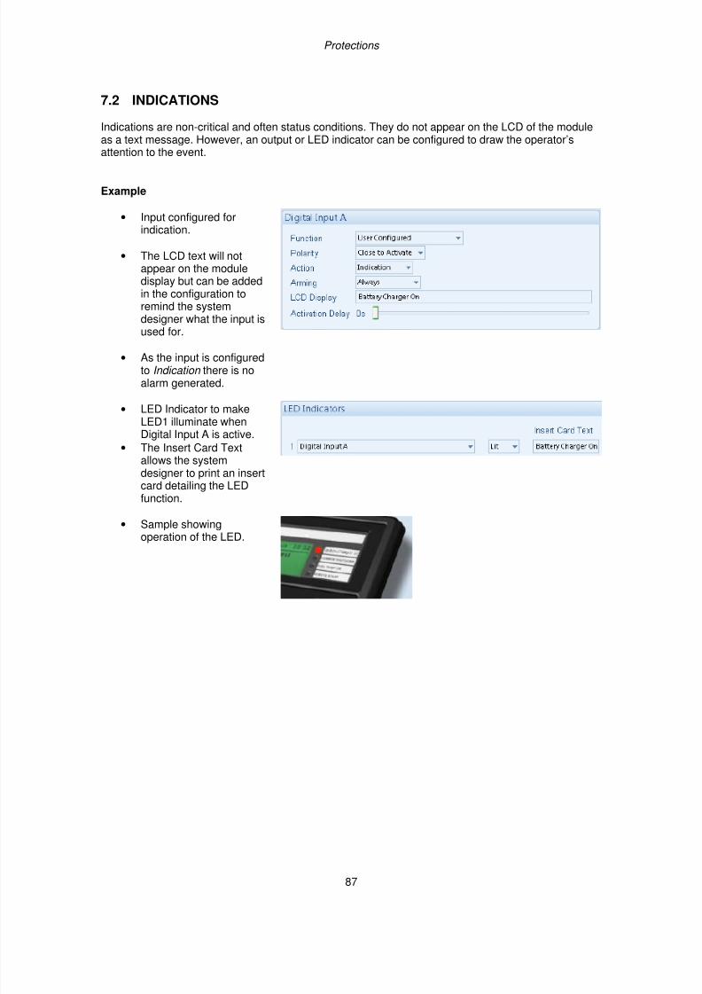
7/14/2019 DEEP SEA 7420
http://slidepdf.com/reader/full/deep-sea-7420-56327e12a4616 87/114
Protections
87
7.2 INDICATIONS
Indications are non-critical and often status conditions. They do not appear on the LCD of the moduleas a text message. However, an output or LED indicator can be configured to draw the operator’sattention to the event.
Example
• Input configured forindication.
• The LCD text will notappear on the moduledisplay but can be addedin the configuration toremind the systemdesigner what the input is
used for.
• As the input is configuredto Indication there is noalarm generated.
• LED Indicator to makeLED1 illuminate whenDigital Input A is active.
• The Insert Card Textallows the systemdesigner to print an insertcard detailing the LEDfunction.
• Sample showingoperation of the LED.
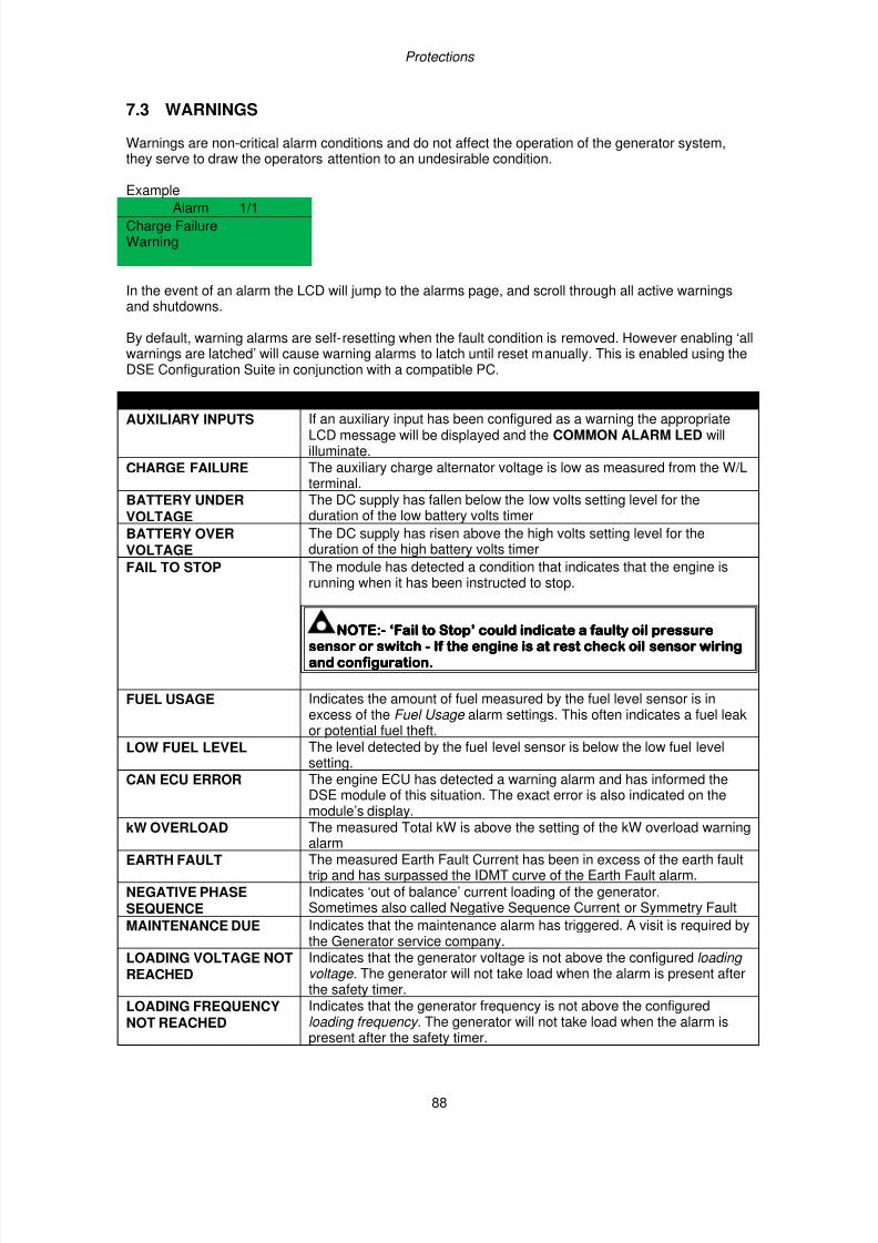
7/14/2019 DEEP SEA 7420
http://slidepdf.com/reader/full/deep-sea-7420-56327e12a4616 88/114
Protections
88
7.3 WARNINGS
Warnings are non-critical alarm conditions and do not affect the operation of the generator system,they serve to draw the operators attention to an undesirable condition.
Example
Alarm 1/1Charge FailureWarning
In the event of an alarm the LCD will jump to the alarms page, and scroll through all active warningsand shutdowns.
By default, warning alarms are self-resetting when the fault condition is removed. However enabling ‘allwarnings are latched’ will cause warning alarms to latch until reset manually. This is enabled using theDSE Configuration Suite in conjunction with a compatible PC.
Display Reason
AUXILIARY INPUTS If an auxiliary input has been configured as a warning the appropriateLCD message will be displayed and the COMMON ALARM LED willilluminate.
CHARGE FAILURE The auxiliary charge alternator voltage is low as measured from the W/Lterminal.
BATTERY UNDERVOLTAGE
The DC supply has fallen below the low volts setting level for theduration of the low battery volts timer
BATTERY OVERVOLTAGE
The DC supply has risen above the high volts setting level for theduration of the high battery volts timer
FAIL TO STOP The module has detected a condition that indicates that the engine isrunning when it has been instructed to stop.
NOTE:NOTE:NOTE:NOTE:---- ‘Fail to Stop’ could indicate a faulty oil pressure‘Fail to Stop’ could indicate a faulty oil pressure‘Fail to Stop’ could indicate a faulty oil pressure‘Fail to Stop’ could indicate a faulty oil pressuresensor or switchsensor or switchsensor or switchsensor or switch ---- If the engine is at rest check oil sensor wiringIf the engine is at rest check oil sensor wiringIf the engine is at rest check oil sensor wiringIf the engine is at rest check oil sensor wiring
and configuration.and configuration.and configuration.and configuration.
FUEL USAGE Indicates the amount of fuel measured by the fuel level sensor is inexcess of the Fuel Usage alarm settings. This often indicates a fuel leakor potential fuel theft.
LOW FUEL LEVEL The level detected by the fuel level sensor is below the low fuel levelsetting.
CAN ECU ERROR The engine ECU has detected a warning alarm and has informed theDSE module of this situation. The exact error is also indicated on themodule’s display.
kW OVERLOAD The measured Total kW is above the setting of the kW overload warningalarm
EARTH FAULT The measured Earth Fault Current has been in excess of the earth faulttrip and has surpassed the IDMT curve of the Earth Fault alarm.
NEGATIVE PHASESEQUENCE
Indicates ‘out of balance’ current loading of the generator.Sometimes also called Negative Sequence Current or Symmetry Fault
MAINTENANCE DUE Indicates that the maintenance alarm has triggered. A visit is required bythe Generator service company.
LOADING VOLTAGE NOTREACHED
Indicates that the generator voltage is not above the configured loading voltage. The generator will not take load when the alarm is present afterthe safety timer.
LOADING FREQUENCY
NOT REACHED
Indicates that the generator frequency is not above the configured
loading frequency. The generator will not take load when the alarm ispresent after the safety timer.
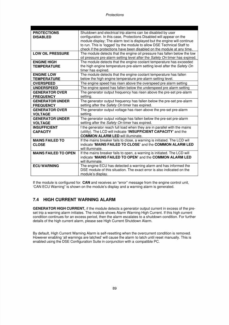
7/14/2019 DEEP SEA 7420
http://slidepdf.com/reader/full/deep-sea-7420-56327e12a4616 89/114
Protections
89
Display Reason
PROTECTIONSDISABLED
Shutdown and electrical trip alarms can be disabled by userconfiguration. In this case, Protections Disabled will appear on themodule display; The alarm text is displayed but the engine will continueto run. This is ‘logged’ by the module to allow DSE Technical Staff tocheck if the protections have been disabled on the module at any time.
LOW OIL PRESSURE The module detects that the engine oil pressure has fallen below the lowoil pressure pre-alarm setting level after the Safety On timer has expired.
ENGINE HIGHTEMPERATURE
The module detects that the engine coolant temperature has exceededthe high engine temperature pre-alarm setting level after the Safety On timer has expired.
ENGINE LOWTEMPERATURE
The module detects that the engine coolant temperature has fallenbelow the high engine temperature pre-alarm setting level.
OVERSPEED The engine speed has risen above the overspeed pre alarm setting
UNDERSPEED The engine speed has fallen below the underspeed pre alarm setting
GENERATOR OVERFREQUENCY
The generator output frequency has risen above the pre-set pre-alarmsetting.
GENERATOR UNDERFREQUENCY
The generator output frequency has fallen below the pre-set pre-alarmsetting after the Safety On timer has expired.
GENERATOR OVERVOLTAGE
The generator output voltage has risen above the pre-set pre-alarmsetting.
GENERATOR UNDERVOLTAGE
The generator output voltage has fallen below the pre-set pre-alarmsetting after the Safety On timer has expired.
INSUFFICIENTCAPACITY
f the generator reach full load when they are in parallel with the mains(utility). The LCD will indicate ‘INSUFFICIENT CAPACITY’ and theCOMMON ALARM LED will illuminate.
MAINS FAILED TOCLOSE
If the mains breaker fails to close, a warning is initiated. The LCD willindicate ‘MAINS FAILED TO CLOSE’ and the COMMON ALARM LED will illuminate.
MAINS FAILED TO OPEN If the mains breaker fails to open, a warning is initiated. The LCD willindicate ‘MAINS FAILED TO OPEN’ and the COMMON ALARM LED
will illuminate.ECU WARNING The engine ECU has detected a warning alarm and has informed the
DSE module of this situation. The exact error is also indicated on themodule’s display.
If the module is configured for, CAN and receives an “error” message from the engine control unit,‘CAN ECU Warning” is shown on the module’s display and a warning alarm is generated.
7.4 HIGH CURRENT WARNING ALARM
GENERATOR HIGH CURRENT, if the module detects a generator output current in excess of the pre-set trip a warning alarm initiates. The module shows Alarm Warning High Current. If this high currentcondition continues for an excess period, then the alarm escalates to a shutdown condition. For furtherdetails of the high current alarm, please see High Current Shutdown Alarm.
By default, High Current Warning Alarm is self-resetting when the overcurrent condition is removed.However enabling ‘all warnings are latched’ will cause the alarm to latch until reset manually. This isenabled using the DSE Configuration Suite in conjunction with a compatible PC.
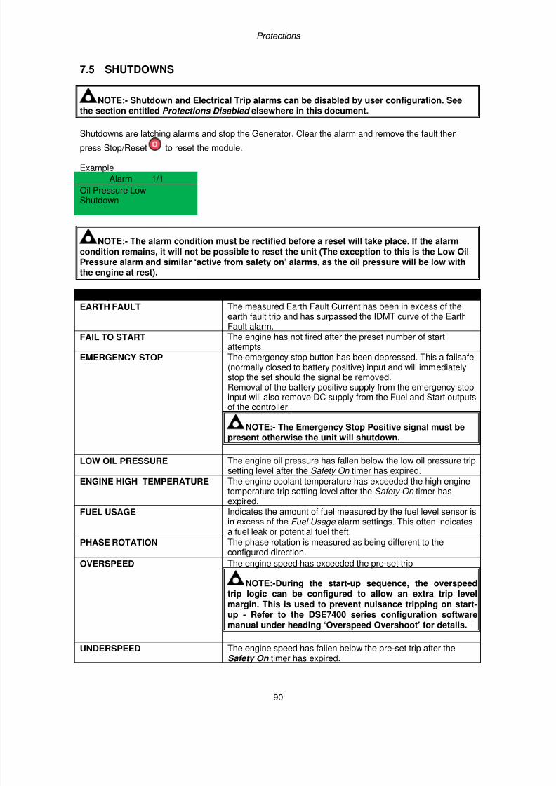
7/14/2019 DEEP SEA 7420
http://slidepdf.com/reader/full/deep-sea-7420-56327e12a4616 90/114
Protections
90
7.5 SHUTDOWNS
NOTE:- Shutdown and Electrical Trip alarms can be disabled by user configuration. Seethe section entitled Protections Disabled elsewhere in this document.
Shutdowns are latching alarms and stop the Generator. Clear the alarm and remove the fault then
press Stop/Reset to reset the module.
Example
Alarm 1/1
Oil Pressure LowShutdown
NOTE:- The alarm condition must be rectified before a reset will take place. If the alarmcondition remains, it will not be possible to reset the unit (The exception to this is the Low Oil
Pressure alarm and similar ‘active from safety on’ alarms, as the oil pressure will be low withthe engine at rest).
Display Reason
EARTH FAULT The measured Earth Fault Current has been in excess of theearth fault trip and has surpassed the IDMT curve of the EarthFault alarm.
FAIL TO START The engine has not fired after the preset number of startattempts
EMERGENCY STOP The emergency stop button has been depressed. This a failsafe(normally closed to battery positive) input and will immediatelystop the set should the signal be removed.
Removal of the battery positive supply from the emergency stopinput will also remove DC supply from the Fuel and Start outputsof the controller.
NOTE:- The Emergency Stop Positive signal must bepresent otherwise the unit will shutdown.
LOW OIL PRESSURE The engine oil pressure has fallen below the low oil pressure tripsetting level after the Safety On timer has expired.
ENGINE HIGH TEMPERATURE The engine coolant temperature has exceeded the high enginetemperature trip setting level after the Safety On timer hasexpired.
FUEL USAGE Indicates the amount of fuel measured by the fuel level sensor is
in excess of the Fuel Usage alarm settings. This often indicatesa fuel leak or potential fuel theft.
PHASE ROTATION The phase rotation is measured as being different to theconfigured direction.
OVERSPEED The engine speed has exceeded the pre-set trip
NOTE:-During the start-up sequence, the overspeedtrip logic can be configured to allow an extra trip levelmargin. This is used to prevent nuisance tripping on start-up - Refer to the DSE7400 series configuration softwaremanual under heading ‘Overspeed Overshoot’ for details.
UNDERSPEED The engine speed has fallen below the pre-set trip after theSafety On timer has expired.
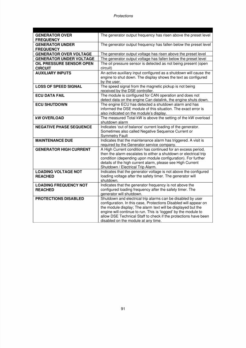
7/14/2019 DEEP SEA 7420
http://slidepdf.com/reader/full/deep-sea-7420-56327e12a4616 91/114
Protections
91
Display Reason
GENERATOR OVERFREQUENCY
The generator output frequency has risen above the preset level
GENERATOR UNDERFREQUENCY
The generator output frequency has fallen below the preset level
GENERATOR OVER VOLTAGE The generator output voltage has risen above the preset level
GENERATOR UNDER VOLTAGE The generator output voltage has fallen below the preset levelOIL PRESSURE SENSOR OPENCIRCUIT
The oil pressure sensor is detected as not being present (opencircuit)
AUXILIARY INPUTS An active auxiliary input configured as a shutdown will cause theengine to shut down. The display shows the text as configuredby the user.
LOSS OF SPEED SIGNAL The speed signal from the magnetic pickup is not beingreceived by the DSE controller.
ECU DATA FAIL The module is configured for CAN operation and does notdetect data on the engine Can datalink, the engine shuts down.
ECU SHUTDOWN The engine ECU has detected a shutdown alarm and hasinformed the DSE module of this situation. The exact error is
also indicated on the module’s display.kW OVERLOAD The measured Total kW is above the setting of the kW overloadshutdown alarm
NEGATIVE PHASE SEQUENCE Indicates ‘out of balance’ current loading of the generator.Sometimes also called Negative Sequence Current orSymmetry Fault
MAINTENANCE DUE Indicates that the maintenance alarm has triggered. A visit isrequired by the Generator service company.
GENERATOR HIGH CURRENT A High Current condition has continued for an excess period,then the alarm escalates to either a shutdown or electrical tripcondition (depending upon module configuration). For furtherdetails of the high current alarm, please see High CurrentShutdown / Electrical Trip Alarm.
LOADING VOLTAGE NOTREACHED
Indicates that the generator voltage is not above the configuredloading voltage after the safety timer. The generator willshutdown.
LOADING FREQUENCY NOTREACHED
Indicates that the generator frequency is not above theconfigured loading frequency after the safety timer. Thegenerator will shutdown.
PROTECTIONS DISABLED Shutdown and electrical trip alarms can be disabled by userconfiguration. In this case, Protections Disabled will appear onthe module display; The alarm text will be displayed but theengine will continue to run. This is ‘logged’ by the module toallow DSE Technical Staff to check if the protections have beendisabled on the module at any time.
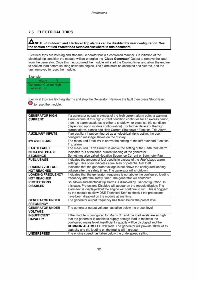
7/14/2019 DEEP SEA 7420
http://slidepdf.com/reader/full/deep-sea-7420-56327e12a4616 92/114
Protections
92
7.6 ELECTRICAL TRIPS
NOTE:- Shutdown and Electrical Trip alarms can be disabled by user configuration. See
the section entitled Protections Disabled elsewhere in this document.
Electrical trips are latching and stop the Generator but in a controlled manner. On initiation of theelectrical trip condition the module will de-energise the ‘Close Generator’ Output to remove the loadfrom the generator. Once this has occurred the module will start the Cooling timer and allow the engineto cool off-load before shutting down the engine. The alarm must be accepted and cleared, and thefault removed to reset the module.
Example
Alarm 1/1
Generator Current HighElectrical Trip
Electrical trips are latching alarms and stop the Generator. Remove the fault then press Stop/Reset
to reset the module.
Display Reason
GENERATOR HIGHCURRENT
If a generator output in excess of the high current alarm point, a warningalarm occurs. If this high current condition continues for an excess period,then the alarm escalates to either a shutdown or electrical trip condition(depending upon module configuration). For further details of the highcurrent alarm, please see High Current Shutdown / Electrical Trip Alarm.
AUXILIARY INPUTS If an auxiliary input configured as an electrical trip is active, the userconfigured message shows on the display.
kW OVERLOAD The measured Total kW is above the setting of the kW overload ElectricalTrip alarm
EARTH FAULT The measured Earth Current is above the setting of the Earth fault alarm.
NEGATIVE PHASESEQUENCE
Indicates ‘out of balance’ current loading of the generator.Sometimes also called Negative Sequence Current or Symmetry Fault
FUEL USAGE Indicates the amount of fuel used is in excess of the Fuel Usage alarmsettings. This often indicates a fuel leak or potential fuel theft.
LOADING VOLTAGENOT REACHED
Indicates that the generator voltage is not above the configured loadingvoltage after the safety timer. The generator will shutdown.
LOADING FREQUENCYNOT REACHED
Indicates that the generator frequency is not above the configured loadingfrequency after the safety timer. The generator will shutdown.
PROTECTIONS
DISABLED
Shutdown and electrical trip alarms is disabled by user configuration. In
this case, Protections Disabled will appear on the module display; Thealarm text is displayed but the engine will continue to run. This is ‘logged’by the module to allow DSE Technical Staff to check if the protectionshave been disabled on the module at any time.
GENERATOR UNDERFREQUENCY
The generator output frequency has fallen below the preset level
GENERATOR UNDERVOLTAGE
The generator output voltage has fallen below the preset level
INSUFFICIENTCAPACITY
If the module is configured for Mains CT and the load levels are so highthat the generator is unable to supply enough load to maintain theconfigured mains level, insufficient capacity will be displayed and theCOMMON ALARM LED will flash. The generator will provide 100% of itscapacity and the loading on the mains will increase.
UNDERSPEED The engine speed has fallen below the underspeed setting
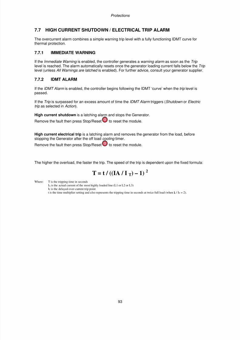
7/14/2019 DEEP SEA 7420
http://slidepdf.com/reader/full/deep-sea-7420-56327e12a4616 93/114
Protections
93
7.7 HIGH CURRENT SHUTDOWN / ELECTRICAL TRIP ALARM
The overcurrent alarm combines a simple warning trip level with a fully functioning IDMT curve forthermal protection.
7.7.1 IMMEDIATE WARNING
If the Immediate Warning is enabled, the controller generates a warning alarm as soon as the Trip level is reached. The alarm automatically resets once the generator loading current falls below the Trip level (unless All Warnings are latched is enabled). For further advice, consult your generator supplier.
7.7.2 IDMT ALARM
If the IDMT Alarm is enabled, the controller begins following the IDMT ‘curve’ when the trip level ispassed.
If the Trip is surpassed for an excess amount of time the IDMT Alarm triggers (Shutdown or Electric trip as selected in Action ).
High current shutdown is a latching alarm and stops the Generator.
Remove the fault then press Stop/Reset to reset the module.
High current electrical trip is a latching alarm and removes the generator from the load, beforestopping the Generator after the off load cooling timer.
Remove the fault then press Stop/Reset to reset the module.
The higher the overload, the faster the trip. The speed of the trip is dependent upon the fixed formula:
T = t / ((IA / I T) – 1) 2
Where: T is the tripping time in seconds
IA is the actual current of the most highly loaded line (L1 or L2 or L3)
IT is the delayed over-current trip point
t is the time multiplier setting and also represents the tripping time in seconds at twice full load (when IA / IT = 2).
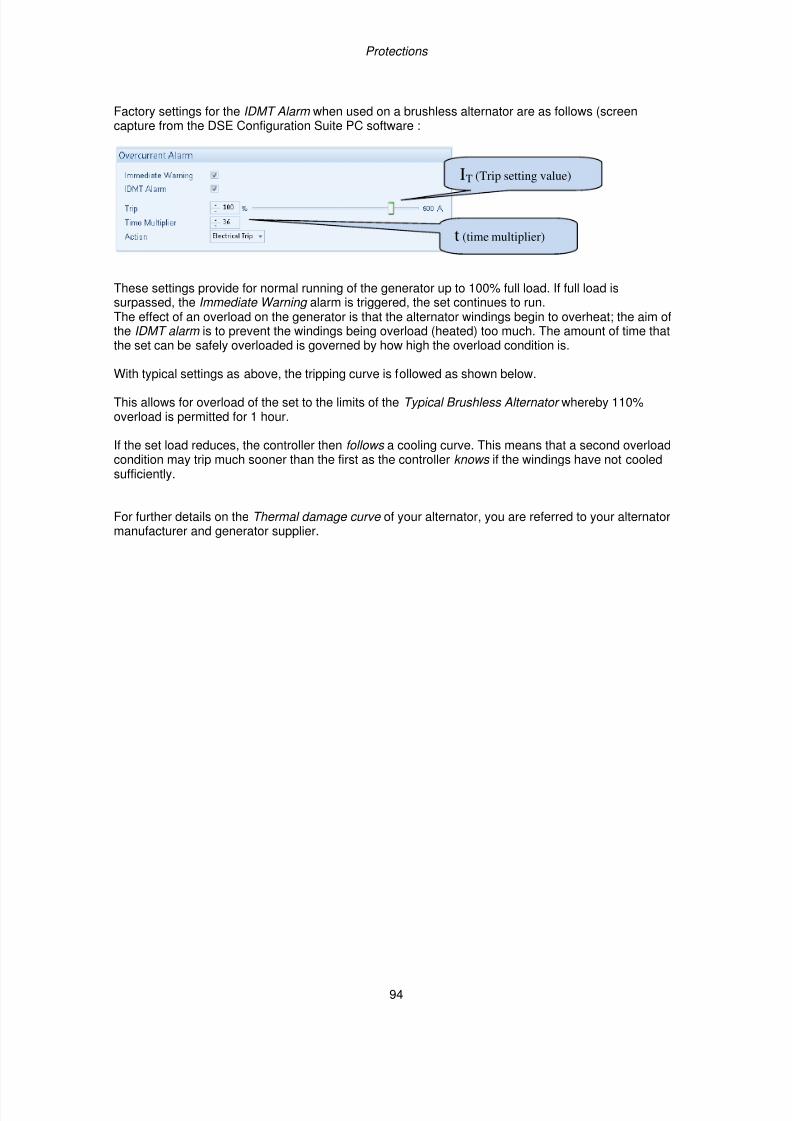
7/14/2019 DEEP SEA 7420
http://slidepdf.com/reader/full/deep-sea-7420-56327e12a4616 94/114
Protections
94
Factory settings for the IDMT Alarm when used on a brushless alternator are as follows (screencapture from the DSE Configuration Suite PC software :
These settings provide for normal running of the generator up to 100% full load. If full load issurpassed, the Immediate Warning alarm is triggered, the set continues to run.The effect of an overload on the generator is that the alternator windings begin to overheat; the aim ofthe IDMT alarm is to prevent the windings being overload (heated) too much. The amount of time thatthe set can be safely overloaded is governed by how high the overload condition is.
With typical settings as above, the tripping curve is followed as shown below.
This allows for overload of the set to the limits of the Typical Brushless Alternator whereby 110%overload is permitted for 1 hour.
If the set load reduces, the controller then follows a cooling curve. This means that a second overloadcondition may trip much sooner than the first as the controller knows if the windings have not cooledsufficiently.
For further details on the Thermal damage curve of your alternator, you are referred to your alternatormanufacturer and generator supplier.
IT (Trip setting value)
t (time multiplier)
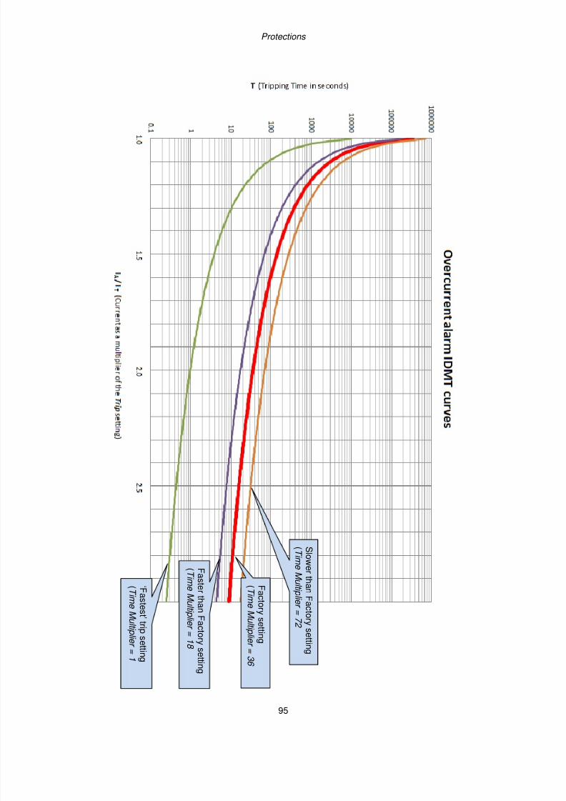
7/14/2019 DEEP SEA 7420
http://slidepdf.com/reader/full/deep-sea-7420-56327e12a4616 95/114
Protections
95
F a c t or y s e t t i n g
( T i m eM ul t i pl i er =
3 6
‘ F a s t e s t ’ t r i p s e t t i n
g
( T i m eM ul t i pl i er =
1
S l ow er t h anF a c t or y s e t t i n g
( T i m eM ul t i pl i er =7 2
F a s t er t h anF a c t or y s e
t t i n g
( T i m eM ul t i pl i er =1 8
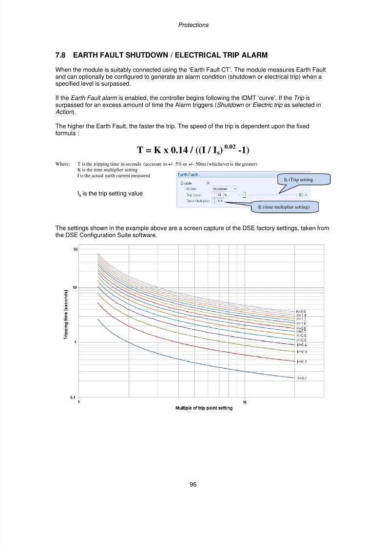
7/14/2019 DEEP SEA 7420
http://slidepdf.com/reader/full/deep-sea-7420-56327e12a4616 96/114
Protections
96
7.8 EARTH FAULT SHUTDOWN / ELECTRICAL TRIP ALARM
When the module is suitably connected using the ‘Earth Fault CT’. The module measures Earth Faultand can optionally be configured to generate an alarm condition (shutdown or electrical trip) when aspecified level is surpassed.
If the Earth Fault alarm is enabled, the controller begins following the IDMT ‘curve’. If the Trip issurpassed for an excess amount of time the Alarm triggers (Shutdown or Electric trip as selected inAction ).
The higher the Earth Fault, the faster the trip. The speed of the trip is dependent upon the fixedformula :
T = K x 0.14 / ((I / Is)0.02
-1)
Where: T is the tripping time in seconds (accurate to +/- 5% or +/- 50ms (whichever is the greater)
K is the time multiplier setting
I is the actual earth current measured
Is is the trip setting value
The settings shown in the example above are a screen capture of the DSE factory settings, taken fromthe DSE Configuration Suite software.
IS (Trip setting
K (time multiplier setting)
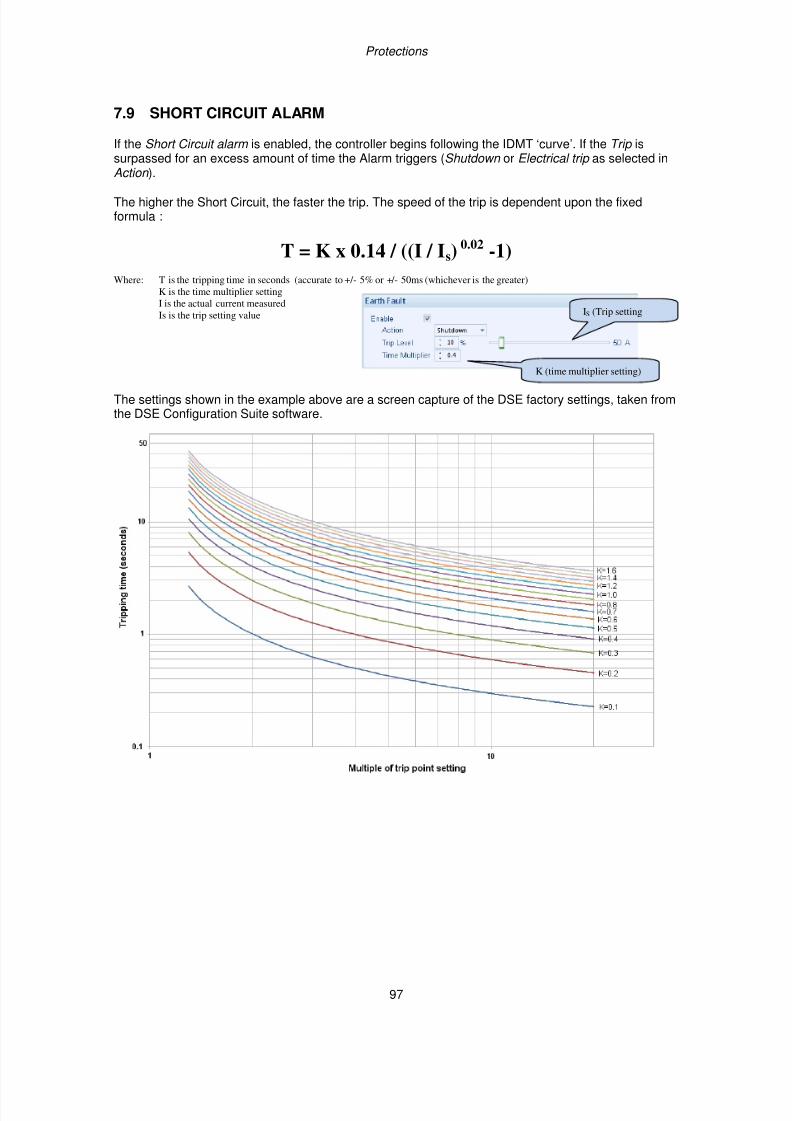
7/14/2019 DEEP SEA 7420
http://slidepdf.com/reader/full/deep-sea-7420-56327e12a4616 97/114
Protections
97
7.9 SHORT CIRCUIT ALARM
If the Short Circuit alarm is enabled, the controller begins following the IDMT ‘curve’. If the Trip issurpassed for an excess amount of time the Alarm triggers (Shutdown or Electrical trip as selected inAction ).
The higher the Short Circuit, the faster the trip. The speed of the trip is dependent upon the fixedformula :
T = K x 0.14 / ((I / Is)0.02 -1)
Where: T is the tripping time in seconds (accurate to +/- 5% or +/- 50ms (whichever is the greater)
K is the time multiplier setting
I is the actual current measured
Is is the trip setting value
The settings shown in the example above are a screen capture of the DSE factory settings, taken fromthe DSE Configuration Suite software.
IS (Trip setting
K (time multiplier setting)
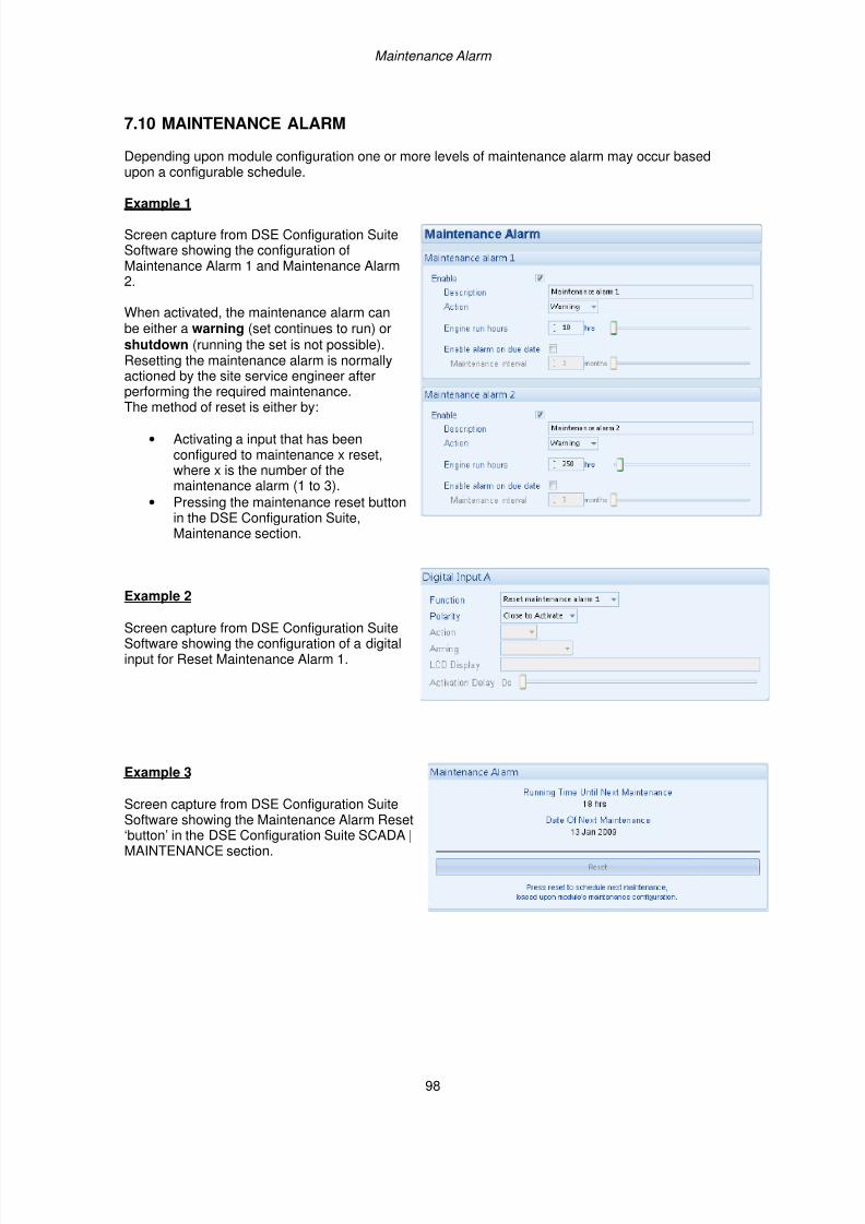
7/14/2019 DEEP SEA 7420
http://slidepdf.com/reader/full/deep-sea-7420-56327e12a4616 98/114
Maintenance Alarm
98
7.10 MAINTENANCE ALARM
Depending upon module configuration one or more levels of maintenance alarm may occur basedupon a configurable schedule.
Example 1
Screen capture from DSE Configuration SuiteSoftware showing the configuration ofMaintenance Alarm 1 and Maintenance Alarm2.
When activated, the maintenance alarm canbe either a warning (set continues to run) orshutdown (running the set is not possible).Resetting the maintenance alarm is normallyactioned by the site service engineer afterperforming the required maintenance.
The method of reset is either by:
• Activating a input that has beenconfigured to maintenance x reset,where x is the number of themaintenance alarm (1 to 3).
• Pressing the maintenance reset buttonin the DSE Configuration Suite,Maintenance section.
Example 2
Screen capture from DSE Configuration SuiteSoftware showing the configuration of a digitalinput for Reset Maintenance Alarm 1.
Example 3
Screen capture from DSE Configuration SuiteSoftware showing the Maintenance Alarm Reset‘button’ in the DSE Configuration Suite SCADA |MAINTENANCE section.
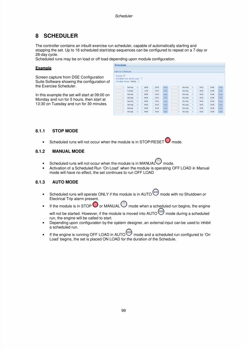
7/14/2019 DEEP SEA 7420
http://slidepdf.com/reader/full/deep-sea-7420-56327e12a4616 99/114
Scheduler
99
8 SCHEDULER
The controller contains an inbuilt exercise run scheduler, capable of automatically starting andstopping the set. Up to 16 scheduled start/stop sequences can be configured to repeat on a 7-day or28-day cycle.
Scheduled runs may be on load or off load depending upon module configuration.
Example
Screen capture from DSE ConfigurationSuite Software showing the configuration ofthe Exercise Scheduler.
In this example the set will start at 09:00 onMonday and run for 5 hours, then start at13:30 on Tuesday and run for 30 minutes.
8.1.1 STOP MODE
• Scheduled runs will not occur when the module is in STOP/RESET mode.
8.1.2 MANUAL MODE
• Scheduled runs will not occur when the module is in MANUAL mode.
• Activation of a Scheduled Run ‘On Load’ when the module is operating OFF LOAD in Manual
mode will have no effect, the set continues to run OFF LOAD
8.1.3 AUTO MODE
• Scheduled runs will operate ONLY if the module is in AUTO mode with no Shutdown orElectrical Trip alarm present.
• If the module is in STOP or MANUAL mode when a scheduled run begins, the engine
will not be started. However, if the module is moved into AUTO mode during a scheduledrun, the engine will be called to start.
• Depending upon configuration by the system designer, an external input can be used to inhibita scheduled run.
• If the engine is running OFF LOAD in AUTO mode and a scheduled run configured to ‘OnLoad’ begins, the set is placed ON LOAD for the duration of the Schedule.
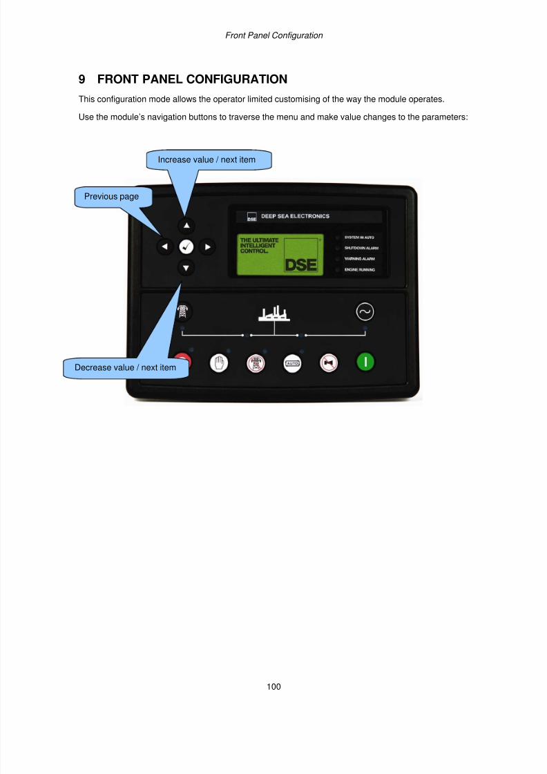
7/14/2019 DEEP SEA 7420
http://slidepdf.com/reader/full/deep-sea-7420-56327e12a4616 100/114
Front Panel Configuration
100
9 FRONT PANEL CONFIGURATION
This configuration mode allows the operator limited customising of the way the module operates.
Use the module’s navigation buttons to traverse the menu and make value changes to the parameters:
Previous page
Increase value / next item
Decrease value / next item
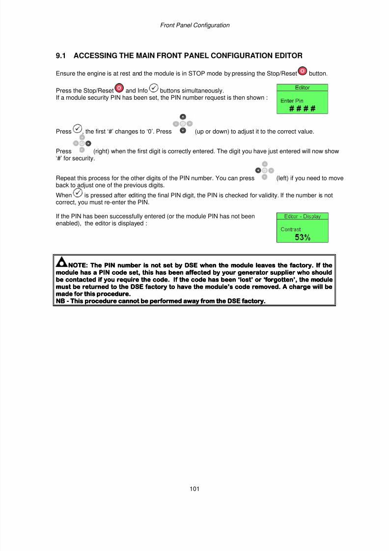
7/14/2019 DEEP SEA 7420
http://slidepdf.com/reader/full/deep-sea-7420-56327e12a4616 101/114
Front Panel Configuration
101
9.1 ACCESSING THE MAIN FRONT PANEL CONFIGURATION EDITOR
Ensure the engine is at rest and the module is in STOP mode by pressing the Stop/Reset button.
Press the Stop/Reset and Info buttons simultaneously.If a module security PIN has been set, the PIN number request is then shown :
Press , the first ‘#’ changes to ‘0’. Press (up or down) to adjust it to the correct value.
Press (right) when the first digit is correctly entered. The digit you have just entered will now show‘#’ for security.
Repeat this process for the other digits of the PIN number. You can press (left) if you need to moveback to adjust one of the previous digits.
When is pressed after editing the final PIN digit, the PIN is checked for validity. If the number is notcorrect, you must re-enter the PIN.
If the PIN has been successfully entered (or the module PIN has not beenenabled), the editor is displayed :
NOTE:NOTE:NOTE:NOTE: The PIN number is not set by DSE when the module leaves the factory. If theThe PIN number is not set by DSE when the module leaves the factory. If theThe PIN number is not set by DSE when the module leaves the factory. If theThe PIN number is not set by DSE when the module leaves the factory. If the
module has a PIN code set, this has been affected by your generator supplier who shouldmodule has a PIN code set, this has been affected by your generator supplier who shouldmodule has a PIN code set, this has been affected by your generator supplier who shouldmodule has a PIN code set, this has been affected by your generator supplier who shouldbe contabe contabe contabe contacted if you require the code. If the code has been ‘lost’ or ‘forgotten’, the modulected if you require the code. If the code has been ‘lost’ or ‘forgotten’, the modulected if you require the code. If the code has been ‘lost’ or ‘forgotten’, the modulected if you require the code. If the code has been ‘lost’ or ‘forgotten’, the modulemust be returned to the DSE factory to have the module’s code removed. A charge will bemust be returned to the DSE factory to have the module’s code removed. A charge will bemust be returned to the DSE factory to have the module’s code removed. A charge will bemust be returned to the DSE factory to have the module’s code removed. A charge will bemade for this procedure.made for this procedure.made for this procedure.made for this procedure.NBNBNBNB ---- This procedure cannot be performed away from the DSThis procedure cannot be performed away from the DSThis procedure cannot be performed away from the DSThis procedure cannot be performed away from the DSE factory.E factory.E factory.E factory.
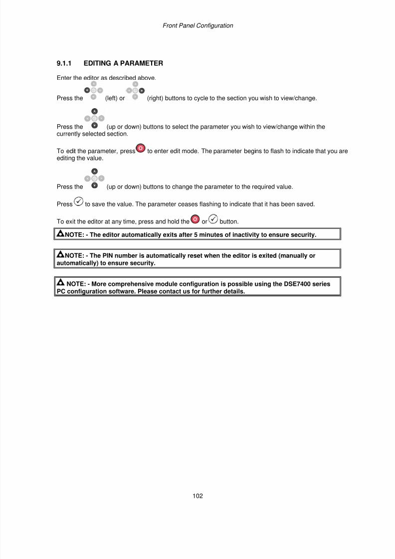
7/14/2019 DEEP SEA 7420
http://slidepdf.com/reader/full/deep-sea-7420-56327e12a4616 102/114
Front Panel Configuration
102
9.1.1 EDITING A PARAMETER
Enter the editor as described above.
Press the (left) or (right) buttons to cycle to the section you wish to view/change.
Press the (up or down) buttons to select the parameter you wish to view/change within thecurrently selected section.
To edit the parameter, press to enter edit mode. The parameter begins to flash to indicate that you areediting the value.
Press the (up or down) buttons to change the parameter to the required value.
Press to save the value. The parameter ceases flashing to indicate that it has been saved.
To exit the editor at any time, press and hold the or button.
NOTE: - The editor automatically exits after 5 minutes of inactivity to ensure security.
NOTE: - The PIN number is automatically reset when the editor is exited (manually orautomatically) to ensure security.
NOTE: - More comprehensive module configuration is possible using the DSE7400 seriesPC configuration software. Please contact us for further details.
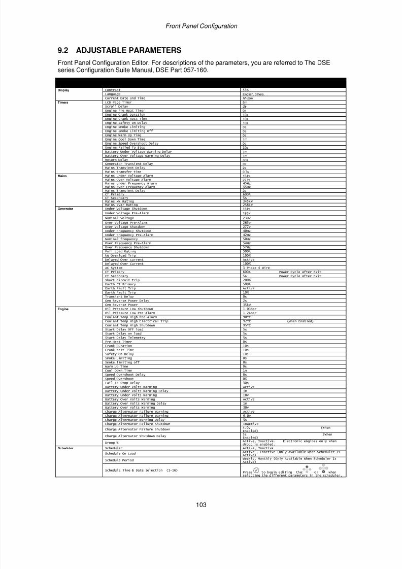
7/14/2019 DEEP SEA 7420
http://slidepdf.com/reader/full/deep-sea-7420-56327e12a4616 103/114
Front Panel Configuration
103
9.2 ADJUSTABLE PARAMETERS
Front Panel Configuration Editor. For descriptions of the parameters, you are referred to The DSEseries Configuration Suite Manual, DSE Part 057-160.
Section Parameter As Shown On Display Values Display Contrast 53%
Language English, others.Current Date and Time hh:mm
Timers LCD Page Timer 5mScroll Delay 2 s
Engine Pre Heat Timer 0sEngine Crank Duration 10sEngine Crank Rest Time 10sEngine Safety On Delay 10sEngine Smoke Limiting 0sEngine Smoke Limiting Off 0sEngine Warm Up Time 0sEngine Cool Down Time 1mEngine Speed Overshoot Delay 0sEngine Failed To Stop 30sBattery Under Voltage Warning Delay 1mBattery Over Voltage Warning Delay 1mReturn Delay 30sGenerator Transient Delay 0sMains Transient Delay 2sMains transfer time 0.7s
Mains Mains Under Voltage Alarm 184vMains Over Voltage Alarm 277vMains Under Frequency Alarm 45Hz
Mains over Frequency Alarm 55Hz Mains Transient Delay 2sCT Primary 600ACT Secondary 5AMains kW Rating 345kWMains kVar Rating 258kW
Generator Under Voltage Shutdown 184v
Under Voltage Pre-Alarm 196v
Nominal Voltage 230v
Over Voltage Pre-Alarm 265v
Over Voltage Shutdown 277v
Under Frequency Shutdown 40Hz
Under Frequency Pre-Alarm 42Hz
Nominal frequency 50Hz
Over Frequency Pre-Alarm 54Hz
Over Frequency Shutdown 57Hz
Full Load Rating 500A
kW Overload Trip 100%
Delayed Over current Active
Delayed Over Current 100%
AC System 3 Phase 4 Wire
CT Primary 600A Power Cycle After Exit
CT Secondary 5A Power Cycle After Exit
Short Circuit Trip 200%
Earth CT Primary 500A
Earth Fault Trip Active
Earth Fault Trip 10%
Transient Delay 0s
Gen Reverse Power Delay 2s
Gen Reverse Power 35kW
Engine Oil Pressure Low shutdown 1.03bar
Oil Pressure Low Pre-Alarm 1.24bar
Coolant Temp High Pre-Alarm 90ºC
Coolant Temp High Electrical Trip 92ºC (When Enabled)
Coolant Temp High Shutdown 95ºC
Start Delay Off load 5s
Start Delay on load 5s
Start Delay Telemetry 5s
Pre Heat Timer 0s
Crank Duration 10s
Crank rest Time 10s
Safety On Delay 10s
Smoke Limiting 0s
Smoke limiting off 0s
Warm Up Time 0s
Cool Down Time 1m
Speed Overshoot Delay 0s
Speed Overshoot 0%
Fail To Stop Delay 30s
Battery Under Volts Warning Active
Battery Under Volts Warning Delay 1m
Battery Under Volts Warning 10v
Battery Over Volts Warning Active
Battery Over Volts Warning Delay 1m
Battery Over Volts Warning 30v
Charge Alternator Failure Warning Active
Charge Alternator Failure Warning 6.0v
Charge Alternator Warning Delay 5s
Charge Alternator Failure Shutdown Inactive
Charge Alternator Failure Shutdown4.0v (WhenEnabled)
Charge Alternator Shutdown Delay5s (WhenEnabled)
Droop %Active, Inactive. Electronic engines only whendroop is enabled.
Scheduler Scheduler Active, Inactive
Schedule On LoadActive , Inactive (Only Available When Scheduler IsActive)
Schedule PeriodWeekly, Monthly (Only Available When Scheduler IsActive)
Schedule Time & Date Selection (1-16) Press to begin editing then or whenselecting the different parameters in the scheduler.
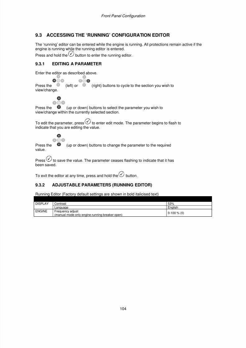
7/14/2019 DEEP SEA 7420
http://slidepdf.com/reader/full/deep-sea-7420-56327e12a4616 104/114
Front Panel Configuration
104
9.3 ACCESSING THE ‘RUNNING’ CONFIGURATION EDITOR
The ‘running’ editor can be entered while the engine is running. All protections remain active if theengine is running while the running editor is entered.
Press and hold the button to enter the running editor.
9.3.1 EDITING A PARAMETER
Enter the editor as described above.
Press the (left) or (right) buttons to cycle to the section you wish toview/change.
Press the (up or down) buttons to select the parameter you wish toview/change within the currently selected section.
To edit the parameter, press to enter edit mode. The parameter begins to flash toindicate that you are editing the value.
Press the (up or down) buttons to change the parameter to the requiredvalue.
Press to save the value. The parameter ceases flashing to indicate that it hasbeen saved.
To exit the editor at any time, press and hold the button.
9.3.2 ADJUSTABLE PARAMETERS (RUNNING EDITOR)
Running Editor (Factory default settings are shown in bold italicised text)
Section Parameter As Shown on Display Factory Settings DISPLAY Contrast 53%
Language English
ENGINE Frequency adjust(manual mode only engine running breaker open)
0-100 % (0)
7/14/2019 DEEP SEA 7420
http://slidepdf.com/reader/full/deep-sea-7420-56327e12a4616 105/114
Commissioning and Fault Finding
105
10 COMMISSIONING10.1 PRE-COMMISSIONING
Before the system is started, it is recommended that the following checks are made:-
• The unit is adequately cooled and all the wiring to the module is of a standard and ratingcompatible with the system. Check all mechanical parts are fitted correctly and that all electricalconnections (including earths) are sound.
• The unit DC supply is fused and connected to the battery and that it is of the correct polarity.
• The Emergency Stop input is wired to an external normally closed switch connected to DC positive.
NOTE:- If Emergency Stop feature is not required, link this input to the DC Positive. Themodule will not operate unless either the Emergency Stop is fitted correctly OR terminal 3 isconnected to DC positive.
• To check the start cycle operation, take appropriate measures to prevent the engine from starting(disable the operation of the fuel solenoid). After a visual inspection to ensure it is safe to proceed,
connect the battery supply. Select and then press the unit start sequence will commence.
• The starter will engage and operate for the pre-set crank period. After the starter motor hasattempted to start the engine for the pre-set number of attempts, the LCD will display ‘Failed to
start . Select the position to reset the unit.
• Restore the engine to operational status (reconnect the fuel solenoid). Select and then
press . This time the engine should start and the starter motor should disengage automatically.If not then check that the engine is fully operational (fuel available, etc.) and that the fuel solenoidis operating. The engine should now run up to operating speed. If not, and an alarm is present,check the alarm condition for validity, then check input wiring. The engine should continue to runfor an indefinite period. It will be possible at this time to view the engine and alternator parameters- refer to the ‘Description of Controls’ section of this manual.
• Select on the front panel, the engine will run for the pre-set cooling down period, then stop.The generator should stay in the standby mode. If not check that there is not a signal present onthe Remote start input.
• Initiate an automatic start by supplying the remote start signal (if configured). The start sequencewill commence and the engine will run up to operational speed. Once the generator is available a
load transfer will take place (if configured), the Generator will accept the load. If not, check thewiring to the Generator Contactor Coil (if used). Check the Warming timer has timed out.
• Remove the remote start signal. The return sequence will begin. After the pre-set time, thegenerator is unloaded. The generator will then run for the pre-set cooling down period, thenshutdown into its standby mode.
• Set the modules internal clock/calendar to ensure correct operation of the scheduler and eventlogging functions. For details of this procedure see section entitled Front Panel Configuration – Editing the date and time.
• If, despite repeated checking of the connections between the controller and the customer’ssystem, satisfactory operation cannot be achieved, then the customer is requested to contact the
factory for further advice on:-
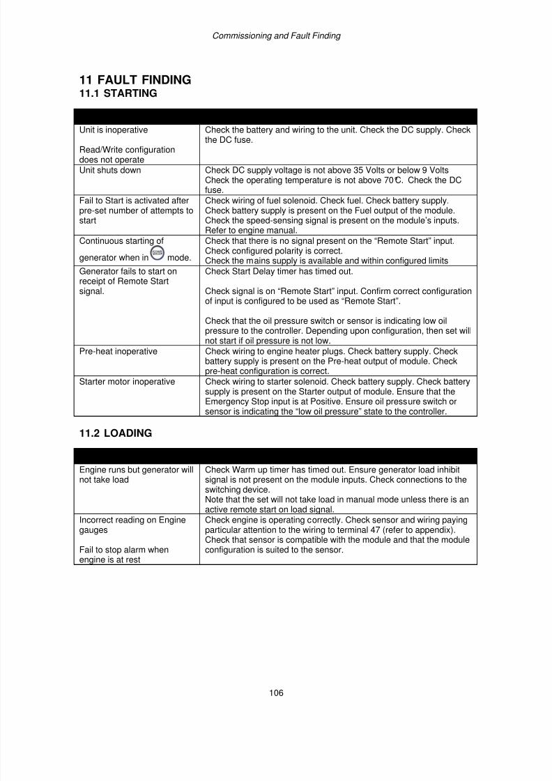
7/14/2019 DEEP SEA 7420
http://slidepdf.com/reader/full/deep-sea-7420-56327e12a4616 106/114
Commissioning and Fault Finding
106
11 FAULT FINDING11.1 STARTING
SYMPTOM POSSIBLE REMEDYUnit is inoperative
Read/Write configurationdoes not operate
Check the battery and wiring to the unit. Check the DC supply. Checkthe DC fuse.
Unit shuts down Check DC supply voltage is not above 35 Volts or below 9 VoltsCheck the operating temperature is not above 70°C. Check the DCfuse.
Fail to Start is activated afterpre-set number of attempts tostart
Check wiring of fuel solenoid. Check fuel. Check battery supply.Check battery supply is present on the Fuel output of the module.Check the speed-sensing signal is present on the module’s inputs.Refer to engine manual.
Continuous starting of
generator when in mode.
Check that there is no signal present on the “Remote Start” input.Check configured polarity is correct.
Check the mains supply is available and within configured limitsGenerator fails to start onreceipt of Remote Startsignal.
Check Start Delay timer has timed out.
Check signal is on “Remote Start” input. Confirm correct configurationof input is configured to be used as “Remote Start”.
Check that the oil pressure switch or sensor is indicating low oilpressure to the controller. Depending upon configuration, then set willnot start if oil pressure is not low.
Pre-heat inoperative Check wiring to engine heater plugs. Check battery supply. Checkbattery supply is present on the Pre-heat output of module. Checkpre-heat configuration is correct.
Starter motor inoperative Check wiring to starter solenoid. Check battery supply. Check batterysupply is present on the Starter output of module. Ensure that theEmergency Stop input is at Positive. Ensure oil pressure switch orsensor is indicating the “low oil pressure” state to the controller.
11.2 LOADING
SYMPTOM POSSIBLE REMEDYEngine runs but generator willnot take load
Check Warm up timer has timed out. Ensure generator load inhibitsignal is not present on the module inputs. Check connections to theswitching device.Note that the set will not take load in manual mode unless there is anactive remote start on load signal.
Incorrect reading on Enginegauges
Fail to stop alarm whenengine is at rest
Check engine is operating correctly. Check sensor and wiring payingparticular attention to the wiring to terminal 47 (refer to appendix).Check that sensor is compatible with the module and that the moduleconfiguration is suited to the sensor.
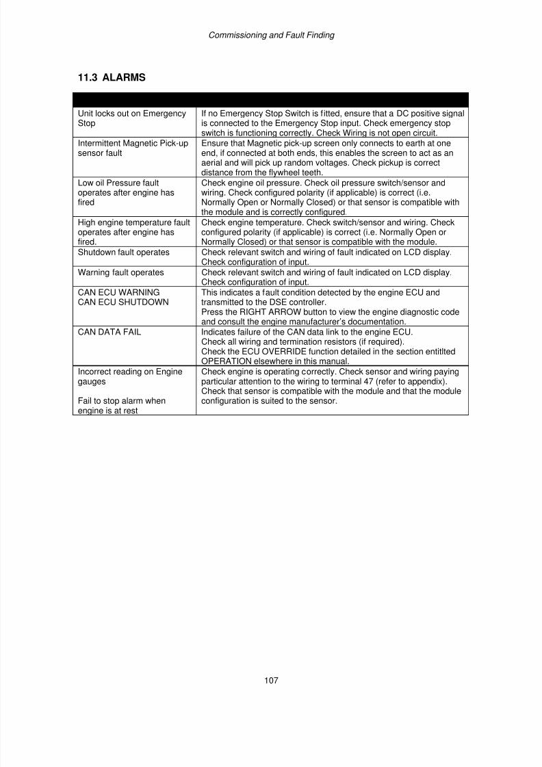
7/14/2019 DEEP SEA 7420
http://slidepdf.com/reader/full/deep-sea-7420-56327e12a4616 107/114
Commissioning and Fault Finding
107
11.3 ALARMS
SYMPTOM POSSIBLE REMEDYUnit locks out on Emergency
Stop
If no Emergency Stop Switch is fitted, ensure that a DC positive signal
is connected to the Emergency Stop input. Check emergency stopswitch is functioning correctly. Check Wiring is not open circuit.Intermittent Magnetic Pick-upsensor fault
Ensure that Magnetic pick-up screen only connects to earth at oneend, if connected at both ends, this enables the screen to act as anaerial and will pick up random voltages. Check pickup is correctdistance from the flywheel teeth.
Low oil Pressure faultoperates after engine hasfired
Check engine oil pressure. Check oil pressure switch/sensor andwiring. Check configured polarity (if applicable) is correct (i.e.Normally Open or Normally Closed) or that sensor is compatible withthe module and is correctly configured.
High engine temperature faultoperates after engine hasfired.
Check engine temperature. Check switch/sensor and wiring. Checkconfigured polarity (if applicable) is correct (i.e. Normally Open orNormally Closed) or that sensor is compatible with the module.
Shutdown fault operates Check relevant switch and wiring of fault indicated on LCD display.Check configuration of input.
Warning fault operates Check relevant switch and wiring of fault indicated on LCD display.Check configuration of input.
CAN ECU WARNINGCAN ECU SHUTDOWN
This indicates a fault condition detected by the engine ECU andtransmitted to the DSE controller.Press the RIGHT ARROW button to view the engine diagnostic codeand consult the engine manufacturer’s documentation.
CAN DATA FAIL Indicates failure of the CAN data link to the engine ECU.Check all wiring and termination resistors (if required).Check the ECU OVERRIDE function detailed in the section entitltedOPERATION elsewhere in this manual.
Incorrect reading on Engine
gauges
Fail to stop alarm whenengine is at rest
Check engine is operating correctly. Check sensor and wiring paying
particular attention to the wiring to terminal 47 (refer to appendix).Check that sensor is compatible with the module and that the moduleconfiguration is suited to the sensor.
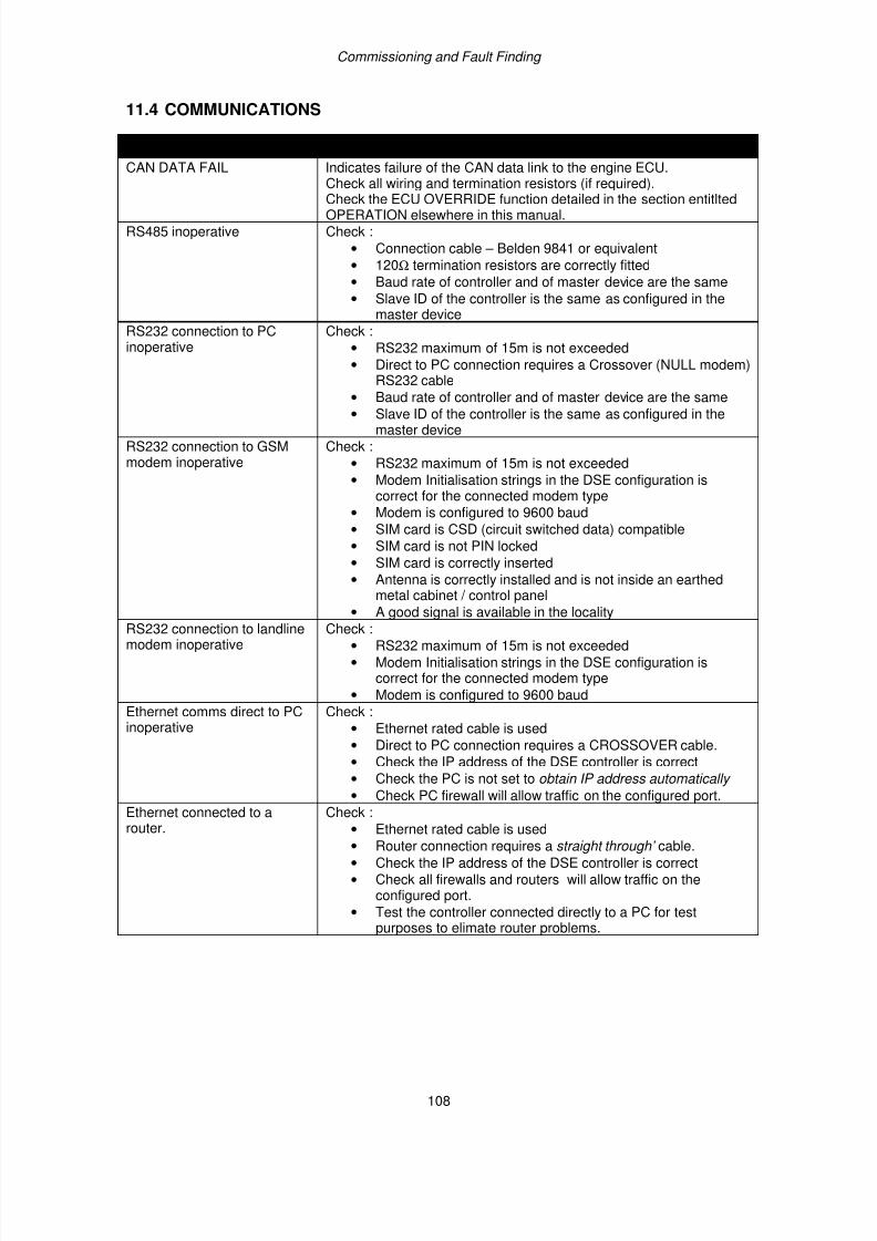
7/14/2019 DEEP SEA 7420
http://slidepdf.com/reader/full/deep-sea-7420-56327e12a4616 108/114
Commissioning and Fault Finding
108
11.4 COMMUNICATIONS
SYMPTOM POSSIBLE REMEDYCAN DATA FAIL Indicates failure of the CAN data link to the engine ECU.
Check all wiring and termination resistors (if required).
Check the ECU OVERRIDE function detailed in the section entitltedOPERATION elsewhere in this manual.RS485 inoperative Check :
• Connection cable – Belden 9841 or equivalent
• 120Ω termination resistors are correctly fitted
• Baud rate of controller and of master device are the same
• Slave ID of the controller is the same as configured in themaster device
RS232 connection to PCinoperative
Check :
• RS232 maximum of 15m is not exceeded
• Direct to PC connection requires a Crossover (NULL modem)RS232 cable
• Baud rate of controller and of master device are the same
• Slave ID of the controller is the same as configured in themaster device
RS232 connection to GSMmodem inoperative
Check :
• RS232 maximum of 15m is not exceeded
• Modem Initialisation strings in the DSE configuration iscorrect for the connected modem type
• Modem is configured to 9600 baud
• SIM card is CSD (circuit switched data) compatible
• SIM card is not PIN locked
• SIM card is correctly inserted
• Antenna is correctly installed and is not inside an earthedmetal cabinet / control panel
• A good signal is available in the localityRS232 connection to landlinemodem inoperative
Check :
• RS232 maximum of 15m is not exceeded
• Modem Initialisation strings in the DSE configuration iscorrect for the connected modem type
• Modem is configured to 9600 baud
Ethernet comms direct to PCinoperative
Check :
• Ethernet rated cable is used
• Direct to PC connection requires a CROSSOVER cable.
• Check the IP address of the DSE controller is correct
• Check the PC is not set to obtain IP address automatically
• Check PC firewall will allow traffic on the configured port.
Ethernet connected to arouter.
Check :
• Ethernet rated cable is used
• Router connection requires a straight through’ cable.
• Check the IP address of the DSE controller is correct
• Check all firewalls and routers will allow traffic on theconfigured port.
• Test the controller connected directly to a PC for testpurposes to elimate router problems.
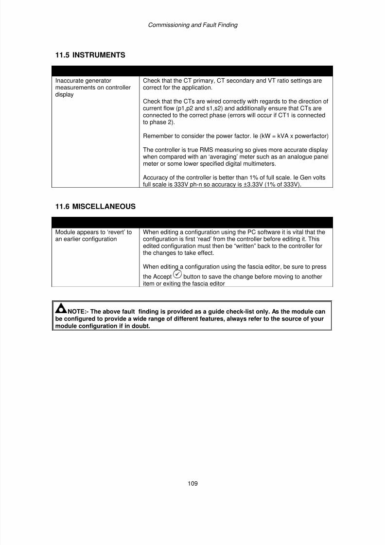
7/14/2019 DEEP SEA 7420
http://slidepdf.com/reader/full/deep-sea-7420-56327e12a4616 109/114
Commissioning and Fault Finding
109
11.5 INSTRUMENTS
SYMPTOM POSSIBLE REMEDYInaccurate generator
measurements on controllerdisplay
Check that the CT primary, CT secondary and VT ratio settings are
correct for the application.
Check that the CTs are wired correctly with regards to the direction ofcurrent flow (p1,p2 and s1,s2) and additionally ensure that CTs areconnected to the correct phase (errors will occur if CT1 is connectedto phase 2).
Remember to consider the power factor. Ie (kW = kVA x powerfactor)
The controller is true RMS measuring so gives more accurate displaywhen compared with an ‘averaging’ meter such as an analogue panelmeter or some lower specified digital multimeters.
Accuracy of the controller is better than 1% of full scale. Ie Gen voltsfull scale is 333V ph-n so accuracy is ±3.33V (1% of 333V).
11.6 MISCELLANEOUS
SYMPTOM POSSIBLE REMEDYModule appears to ‘revert’ toan earlier configuration
When editing a configuration using the PC software it is vital that theconfiguration is first ‘read’ from the controller before editing it. Thisedited configuration must then be “written” back to the controller forthe changes to take effect.
When editing a configuration using the fascia editor, be sure to press
the Accept button to save the change before moving to anotheritem or exiting the fascia editor
NOTE:- The above fault finding is provided as a guide check-list only. As the module canbe configured to provide a wide range of different features, always refer to the source of yourmodule configuration if in doubt.
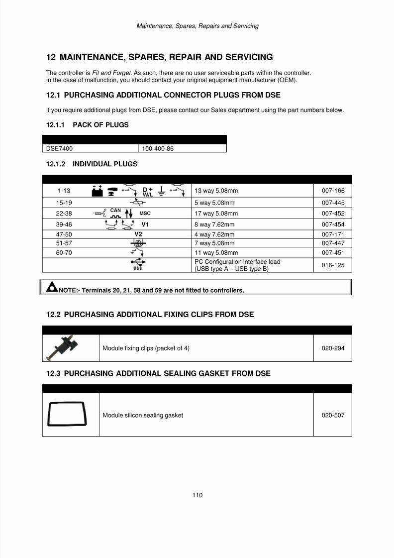
7/14/2019 DEEP SEA 7420
http://slidepdf.com/reader/full/deep-sea-7420-56327e12a4616 110/114
Maintenance, Spares, Repairs and Servicing
110
12 MAINTENANCE, SPARES, REPAIR AND SERVICING
The controller is Fit and Forget . As such, there are no user serviceable parts within the controller.In the case of malfunction, you should contact your original equipment manufacturer (OEM).
12.1 PURCHASING ADDITIONAL CONNECTOR PLUGS FROM DSE
If you require additional plugs from DSE, please contact our Sales department using the part numbers below.
12.1.1 PACK OF PLUGS
Module type Plug Pack Part Number
DSE7400 100-400-86
12.1.2 INDIVIDUAL PLUGS
Module Terminal Designation Plug Description Part No.
1-13 13 way 5.08mm 007-166
15-19 5 way 5.08mm 007-445
22-38 MSC 17 way 5.08mm 007-452
39-46 V1 8 way 7.62mm 007-454
47-50 V2 4 way 7.62mm 007-171
51-57 7 way 5.08mm 007-447
60-70 11 way 5.08mm 007-451
PC Configuration interface lead(USB type A – USB type B)
016-125
NOTE:- Terminals 20, 21, 58 and 59 are not fitted to controllers.
12.2 PURCHASING ADDITIONAL FIXING CLIPS FROM DSE
Item Description Part No.
Module fixing clips (packet of 4) 020-294
12.3 PURCHASING ADDITIONAL SEALING GASKET FROM DSE
Item Description Part No.
Module silicon sealing gasket 020-507
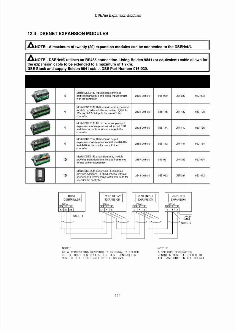
7/14/2019 DEEP SEA 7420
http://slidepdf.com/reader/full/deep-sea-7420-56327e12a4616 111/114
DSENet Expansion Modules
111
12.4 DSENET EXPANSION MODULES
NOTE:- A maximum of twenty (20) expansion modules can be connected to the DSENet®.
NOTE:- DSENet® utilises an RS485 connection. Using Belden 9841 (or equivalent) cable allows forthe expansion cable to be extended to a maximum of 1.2km.DSE Stock and supply Belden 9841 cable. DSE Part Number 016-030.
Item Description
DSE Part Numbers
Max No.supported
Model ordernumber
Salesliterature
Operatormanual
InstallationInstructions
4Model DSE2130 input module providesadditional analogue and digital inputs for usewith the controller.
2130-001-00 055-060 057-082 053-033
4
Model DSE2131 Ratio-metric input expansion
module provides additional restive, digital, 0-10V and 4-20ma inputs for use with thecontroller.
2131-001-00 055-115 057-139 053-125
4
Model DSE2133 RTD/Thermocouple inputexpansion module provides additional RTDand thermocouple inputs for use with thecontroller.
2133-001-00 055-114 057-140 053-126
4
Model DSE2152 Ratio-metric outputexpansion module provides additional 0-10Vand 4-20ma outputs for use with thecontroller.
2152-001-00 055-112 057-141 053-134
10Model DSE2157 expansion relay moduleprovides eight additional voltage free relaysfor use with the controller
2157-001-00 055-061 057-083 053-034
10
Model DSE2548 expansion LED moduleprovides additional LED indications, internalsounder and remote lamp test/alarm mute foruse with the controller.
2548-001-00 055-062 057-084 053-032
7/14/2019 DEEP SEA 7420
http://slidepdf.com/reader/full/deep-sea-7420-56327e12a4616 112/114
Disposal & Warranty
112
13 WARRANTY
DSE provides limited warranty to the equipment purchaser at the point of sale. For full details of any applicablewarranty, you are referred to your original equipment supplier (OEM).
14 DISPOSAL
14.1 WEEE (WASTE ELECTRICAL AND ELECTRONIC EQUIPMENT)
Directive 2002/96/ECIf you use electrical and electronic equipment you must store, collect, treat, recycle and dispose ofWEEE separately from your other waste.
14.2 ROHS (RESTRICTION OF HAZARDOUS SUBSTANCES)
Directive 2002/95/EC: 2006To remove specified hazardous substances (Lead, Mercury, Hexavalent Chromium, Cadmium, PBB &PBDE´s)
Exemption Note: Category 9. (Monitoring & Control Instruments) as defined in Annex 1B of the WEEEdirective will be exempt from the RoHS legislation. This was confirmed in the August 2005 UK´s Department ofTrade and Industry RoHS REGULATIONS Guide (Para 11).
Despite this exemption, DSE has been carefully removing all non RoHS compliant components from oursupply chain and products.When this is completed, a Lead Free & RoHS compatible manufacturing process will be phased into DSEproduction.
This process that is almost complete and is being phased through different product groups.

7/14/2019 DEEP SEA 7420
http://slidepdf.com/reader/full/deep-sea-7420-56327e12a4616 113/114
113
This page is intentionally left blank

7/14/2019 DEEP SEA 7420
http://slidepdf.com/reader/full/deep-sea-7420-56327e12a4616 114/114
This page is intentionally left blank.