deep: a knowledge-based (expert) system for electric plat design
TRANSCRIPT

Pergamon
Computing .Systems in Engineering, Vol. 6, No. 6, pp. 497~509, 1995 Copyright 0 1995 Elsevier Science Ltd
0956-0561(95)00053-4 Printed in Great Britain. All rights reserved 0956-0521/95 $9.50 + 0.00
DEEP: A KNOWLEDGE-BASED (EXPERT) SYSTEM FOR ELECTRIC PLAT DESIGN
CLIVE L. DYM, MATTHEW D. SUMMERS, CRAIG T. DEMEL and CRAIG S. WONG Department of Engineering, Harvey Mudd College, Claremont, CA91711, U.S.A.
(Received 17 November 1994; accepted in revised form 21 June 1995)
Abstract-This paper describes the development of a knowledge-based system to assist Southern California Edison (SCE) in the design of electric service facilities for residential developments. The system supports SCE planners both by performing spatial reasoning in support of the design task and by performing more routine parts of the design. The paper also outlines the technical issues underlying how this knowledge-based designer’s assistant is being integrated into the CADD environment currently being used throughout the SCE-grid
1. INTRODUCTION
A significant problem for Southern California Edison (SCE) is the design of service distribution facilities for new residential developments. The design of such plats, as they are often called, is done by experienced service planners and designers who spend, on aver- age, eight hours on a first-draft layout of distribution and service equipment for a residential development of 3G50 houses.’ The design process includes: calculating and specifying demand requirements for the development; identifying feedpoints; establishing a spatial distribution of transformers and handholes; specifying mounts and equipment for transformers and handholes; establishing primary, secondary, and service lines; and specifying the materials lists for all equipment and lines.
The heart of the problem just outlined is a design task that requires:
(1) spatial reasoning, the ability to reason about the geometry of a plat, the routing of service lines, and the placement of particular facilities;
(2) component selection, the ability to choose from a large array the particular components or subsystems needed to perform specified functions;
(3) and component configuration, the ability to set up or configure a subsystem in just the right way to obtain the specified behavior.
This design task requires the designer to make qualitative and quantitative judgements while reason- ing geometrically, algorithmically and heuristically about both physical objects and more abstract con- cepts. Knowledge-based (expert) systems (KBESs) have proven to be very useful tools dealing with the kind of qualitative information and subjective, experiential knowledge that is applied in such design
tasks.2 In fact, the design task outlined above has some elements in common with other KBES design systems, for example, the PRIDE expert system for the mechanical design of paper handling subsystems for copier machines3 This system begins with a spatial layout problem wherein the designer lays out a geometric path along which paper will travel through the copier, subject to certain constraints on both geometry and function, and then proceeds through a process of selecting and configuring the precise components needed to physically move paper through the copier. Thus, the design task captured in PRIDE has much in common with the residential plat design task.
A second related system is the LSC Advisor prototype that automatically checks the blueprints of an architectural design for conformance of the Life Safety Code (LSC) of the National Fire Protection Association (NFPA).4 The common point here is that the LSC Advisor uses an integrated representation of building components which allows their geometric identification and specification within a CADD system simultaneously with their identification as physical and conceptual objects which the designer (or system user) can reason about. In this represen- tation, for example, a wall can be represented within a data structure which has within it the wall’s geometric location, height and width, as well as the identification of: the material of which the wall is made, any doors or windows that may be in the wall, and the role of the wall in the boundary of a smoke zone or a fire zone. The code-checking task of the LSC Advisor thus parallels the work outlined below because both tasks require description of and reason- ing about physical and conceptual objects which are initially identified by their location in a CADD drawing of some type.
Just recently, partial results of a similar project under the sponsorship of the Puget Sound Power &
497

498 Clive L. Dym et al.
Light Company have been reported.5*6 A comprehen- sive proposed blackboard-based architecture is described5 and some implementation results are presented.6 That system differs from the present work in an important way in that it is intended to automate the design process, whereas DEEP is intended as a designer’s assistant which encourages strong interaction by the user (c$ Sections 3.1 and 5).
This paper describes the completion of a prototype KBES called DEEP (Design of Edison Electric Plats) that performs the de;gn task %tlined above- The paper is organized as follows. Section 2 outlines how this project was organized and completed. Section 3 discusses the design knowledge encapsulated, with special emphasis placed on the design procedure and its representation. Section 4 outlines the development requirements and architecture of a real-time system that is now being implemented for SCE for daily use by their designers. This section also ideqtifies some of the advantages that the sponsor, SCE, expects to gain from the implementation of the DEEP system. Concluding remarks appear in Section 5.
2. ORGANIZATION AND COMPLETION OF THE DEEP PROJECT
The project had as its primary focus the completion of a demonstration prototype of the DEEP system which would show potential users, designers and planners, and their managers, that an expert system could provide guidance about the design of service facilities for residential developments. The DEEP knowledge base was derived from extensive inter- viewing of SCE service designers and planners, as well as on the formal design requirements published by SCE.7 The DEEP prototype was developed within a KBES programming environment, or “shell”, Intellicorp’s Kappa-PC (accessed through Windows). As developed, the DEEP prototype is a stand-alone
I ,
4 -3
I I KIdI I
Fig. 1. A stylized residential plat used within the DEEP system.
system that requires manual input of plat geometry and service data before the design can proceed.
2.1. DEEP architecture
DEEP is envisioned as a designer’s assistant. It is not a replacement for customer service designers and planners. DEEP is meant to be an interactive tool that applies its knowledge base when requested by the designer. It is intended to support the work done by these experts so that they can complete a “routine”, first-draft plat design in two hours or less, rather than the eight hours currently required. Thus, although
User 4
Basemap of Sevice Area
Graphical + Kappa W output
A
Information/ Knowledge/ Rule Base
Fig. 2. The architecture of the DEEP demonstration system.

DEEP 499
DEEP could perhaps complete designs in a nearly automatic way, it is intended to be used as an interactive design tool, supporting the designer as s/he works through all the steps in the design task.
The original intent was that the DEEP demonstration system would appear to the designer as an extension of the Utility Design System (UDS) design environment. The basic geographical and geometrical descriptions of the residential develop- ments for which service is being designed-the basemaps (see Fig. I)--were drawn directly in Kappa- PC, with the architecture of the DEEP demonstration system being as shown in Fig. 2. (The architecture of prototype being implemented is discussed in detail in Section 4.) UDS builds on the basemap drawing by allowing the planner to place and manipulate electrical plat components. UDS also incorporates the needed algorithmic calculations of the electrical services of the plats as they are designed.
2.2. Knowledge acquisition
A knowledge-based (expert) system is knowledgeable or expert only to the extent that it captures the expertise of, in this instance, a knowledgeable designer. In fact, the basic idea of a KBES is that it will produce for a user the equivalent of an expert’s advice, including not only some specific guidance, but also the reasoning path by which the system arrived at that result. Therefore, the HMC project team worked very closely with SCE grid experts to understand how the system currently works, what kind of data and reasoning are used by the experts, and what kinds of advice are most desirable in terms of DEEP’s “product”. This part of the project, the knowledge acquisition phase,*19 was central to the entire project.
The interviews with SCE planners and designers were conducted during the summer of 1992. The guidelines under which the experts were interviewed had been successfully applied in order, complex in- dustrial environments.’ Specifically, the interviews were conducted in a protocol where the designers were asked to do their design tasks, rather than being asked to explain how they did these tasks. This enabled the project team to develop its own, indepen- dent model of the design task.* In addition, by interviewing several designers in different offices and over a period of several weeks, the project team was able to identify (1) a basic approach to this design task that was shared by all designers, and (2) a set of subtasks that were uniquely done by individual designers. This was important for two reasons. First, that there was a common view of the basic design task made its encapsulation within DEEP worthwhile.’ To be sure, there were individual differences and nuances, but these were typically about small or relatively marginal items.
Second, the project team took the view that it wished to build an expert system that will assist any and all planners with plat design, not just one. Thus, CSE 6,&B
DEEP should be a tool that all designers can integrate into their own unique planning process. Thus, for this purpose as well, it was important to distinguish tasks that all planners follow from those that are unique only to some. DEEP was designed to perform the common, shared design task and follow the common rules while allowing the planner take over at any point and apply his/her own knowledge. In this way DEEP integrates the experts’ own “rule book” with the “rule book” or heuristics shared by all planners. Also, it is worth pointing out that while most of the knowledge came from the experts, the DEEP system does incorporate the design expertise that has already been codified and formalized in relevant SCE publications.’
3. THE DESIGN PROCESS CAPTURED IN DEEP
Many, and often conflicting, factors go into a good plat design, including: meeting load requirements, minimizing the system’s overall cost, insuring the system’s serviceability, and trying to meet customer requests. Some of these factors can be done with simple algorithms (e.g. load requirements), while others require a planner’s involvement (e.g., customer requests). Also, there is no single ordering to the subtasks that must be done to complete a design. For example, some designers think it important to find the feedpoint before any secondary design can begin; others complete a secondary design even before considering the feedpoint. And while each planner interviewed came up with a satisfactory design, there were other points of contention about the design method. Thus, it should be kept in mind that the design process described in this section-and simulated in DEEP-is a model for the interactive design process captured in DEEP that allows each planner to use his/her own unique style or “rule book” when designing a residential plat.
3.1. Organizing objects in DEEP
The planning process begins with a subdivision map with lots and streets, centerlines and service points. To the computer, these are just points and lines that have no identifiable meaning. In order to give this data some meaning, it must be stored in a meaningful way. The data structure chosen for the DEEP system is an object hierarchy (Fig. 3) based on the objects and frames described in Section 2.3. Each object is represented as a class, or as a member of a class called an instance. Each class has attributes, or slots, that provide information about all of the sub- classes or instances within the class. For example, the class “Lots” would store information about each of the lots from the basemap as instances within the class (Fig. 4). Each lot has a service point and a frontage line, so each instance holds the coordinates of these points as values of the corresponding slots. This type of data structure makes it relatively easy to store a large amount of information about an object

500 Clive L. Dym et al.
/HI-I1 Handhole&‘m
‘HH3 structures
XFRZ5----’ XFR25_1
“XFR50 1 XFRSO e=:_ XFR50-2 -
XFR75- - - - - XFR75_1
,0 TFConfigl ,/,M TFConfig2
Configurations +-- TFConfig4 - TFConfig3
e+ ‘7. TFConfig5
’ TFConfig6
DEEP
8 \
Primary < 4 M Primary_1 ‘-Primary_2
Cables
c
00 * Secondary1 Secondary fr-- Secondary_2
‘? _ Secondary-3 ’ Secondary-4
,/ Service-1
Service /,- Service 2
$ - - . sewice3 *\ \; Service-4
‘Service_5
Fig. 3. The object structure of the DEEP system.
LOTS
SLOT (data type)
NUMBEWNAME (number) Xl (number) Yl (number) X2 (number) Y2 (number) Xservice (number) Yservice (number) STREETSIDE (N,S,E,W) BACK_TO_BACK (a lot) DISTANCE (number)
STREETS
SLOT (data type)
NAME (text) Xstart (number) Y-start (number) Xend (number) Yend (number) START (text) END (text) CONFIGURE (T/F) ADJACENT (a STREET) PRIORITY (a number)
Fig. 4. Important attributes of lots and streets in DEEP.

DEEP
pz=
Fig. 5. A flowchart of the design process in DEEP.
501
in a condensed and efficient form. It also facilitates scanning and sorting the data, as well as the perform- ance of calculations on the values of attributes of particular objects.
Figure 5 traces the design process of the DEEP demonstration system. This process was designed to follow as closely as possible the actual process used by SCE planners. Its individual steps are detailed in the following sections.
3.2. Representing preliminary information and plat geometry
To initiate the design of residential tract housing plats, the planner must obtain certain preliminary information. Some of this information is about the climate zone, the type of transformer, the average size of a house in the development, and the average size (tonnage) of the air conditioner units. The DEEP prototype also requires that the designer enters this information. From this information, ‘DEEP calcu- lates values for the maximum service and flicker for each type of transformer (e.g., 50 kVa Padmount) to be used from the tables given in the SCE design standards manual.’ (Since the values given in the tables are guidelines, a real-time implementation of DEEP would likely do the actual calculations for the necessary values, using basic formulas from the relevant engineering and physics.) The remaining part of the preliminary information that must be acquired is the graphical information contained on the basemap, namely the locations of the lots and streets.
The ultimate goal of any plat design is to provide service for each lot-the lot being the basic building block for plat design. Changes in the information about a lot will produce variations in the design. Each lot frame (Fig. 4) has slots that contain information about the lot’s location (e.g., coordinates, which side of the street), its distance from the “start” of the street, and other nearby services along the same street (back-to-back services). Note that the size of each house, its air conditioning unit and its requisite demand, which are also attributes of lots, do not appear in each instance. This is because these particular data are global averages for the entire subdivision, which are thus taken as equal for each lot, and so they are stored at the class-rather than the instance-level.
Each lot is represented in DEEP by the coordinate pairs of three basic points: the two points at the corners that define the frontage on the street (Xl, Yl) and (X2, Y2), and the point at which the service is
attached to the house (Xservice, Yservice). In addition to these three points, the particular street and the side of the street on which the lot is on must be identified by the planner. (For the real-time implementation of DEEP, however, it is envisioned that a graphical interface with AutoCAD or other graphics package will be developed which will automatically supply the required information.)
After this basic information (i.e., the five sets of geometrical information and the variables defining the global size of the service) is entered, DEEP can calculate what it needs to know about any given lot: the service setback (the distance from the service point to the street), the lot frontage (the width of the lot along the street), the point where the service comes out to the street, and whether or not two lots are back-to-back.
Streets can be viewed as the “containment structure” for lots. A street is defined not only by the start and end points of its centerline, but also by the list of the lots it contains. Each street is represented as an instance of the class STREETS (Fig. 4) which has slots for: the street name; the coordinates of the “start” and “end” points of the street centerline; and values of the START and END slots, which would be one of the following: FEEDPOINT, CUL_.DE__SAC, EDGE, or the name of the street that it intersects. Street intersections occur only at the start and end of a street. (Again, with the real-time system utilizing a graphical interface, this information can be determined automatically.)
All distances are based on centerline stationing in the DEEP prototype. Everything on the street has a station (distance) from the start of the street. This allows for quick estimations of any distances that must be calculated and for quick sorting of objects. It also maintains the option of placing structures on either side of the street (because distance is unaffected by street side).
3.3. Requirements and goals
The requirements that govern this design are that each service on the basemap must have voltage drop and flicker that are less than specified maximum allowable levels. Voltage drop is the difference between the voltage at the service point and the transformer voltage. Flicker is the amount of short- term voltage drop that can occur when high-power appliances (e.g., air conditioners) are turned on. At present, the maximum allowable levels are 3% for voltage drop and 5% for flicker.

502 Clive L. Dvm er al
The driving force behind residential plat design is cost minimization. This is achieved by minimizing the number of transformers, the number of handholes, and the length and size of cable runs. Unfortunately, voltage drop and flicker are reduced by increasing cable thickness and reducing cable lengths, which in turn requires an increase in the numbers of trans- formers and handholes. Thus, there is a balance to maintain between reducing costs and meeting minimum behavioral requirements.
In the present model, within DEEP, a “brute force” calculation was considered but not used to achieve the least expensive design. In this calculation, a straightforward calculation of the costs of all possible combinations of transformer-to-lot assign- ments is performed, and it is left to the user/designer to choose the final combination. Although there is more than adequate computing power available to do such a calculation as an “optimal design” algorithm, designers apply a number of heuristics and deal with various restrictions so as to obtain a more efficient and practical choice. Further, as has already been noted (cf: Section 2.1), DEEP was designed to be a designer’s assistant, so that room has been left in many places in the design process for designers and planners to interact with the system and provide input to it.
3.4. Clustering
A cluster is defined as a group of lots that are served by a single transformer. Although SCE planners did not identify a formal process for cluster- ing lots, they did appear to progress through the basemap in the same fashion. They “redlined” the basemap one cluster at a time, meaning that for each cluster a transformer and handholes were placed and cable was run. This is one point where the process modeled in DEEP differs from what is actually done by the planners. DEEP completes clustering for the entire basemap, assigning every lot to a transformer, before any handholes are placed or cables are run. DEEP was designed this way in order to simulate some of the spatial reasoning exhibited by the plan- ners; although the clusters were treated individually, it seems that all planners mentally synthesize a rough clustering of all lots before they do any redlining.
The spatial reasoning involved in clustering is one of the more difficult parts of plat design, involving as it does a great deal of experiential knowledge on the part of the planner. Inasmuch as clustering is a highly idiosyncratic process, no single model could accu- rately incorporate the approaches taken by all SCE planners. Thus, DEEP’s clustering rule structure and algorithm guides a planner through a clustering
I Determine Order of Streets to Be Clustered I
Consider Street With Next Highest Priority
I +
Find Combination - Determine Appropriate A Combine With of Transformers Action Other Lots
4 J 4 Choose Best Move Lots to Combination
Isolate Adjacent Street
4 J Is Excess Over 20% Choose Best I
of 75kVa:Maxservices? Transformer
Move Lots to Is Combination , Assign Lots to Adjacent Street? no Satisfactory? Yes Transformers
I I x I
continue to transformer placement
Fig. 6. The clustering process in DEEP.

process and provides suggestions as to how lots could be grouped. However, in the more difficult cases the designer is asked to make the final determination of how lots should be clustered.
One of the consistent preferences displayed by planners was that lots on the same street should be grouped into clusters whenever possible. This is the starting point used in the DEEP prototype; i.e., lots on the same street are grouped and then each of the streets is considered separately. (This does not mean that clusters cannot include lots from more than one street, only that initially, lots with a common street are taken as a group.) When all of the lots on a street have been assigned to a cluster and the CON FIG U R E slot for that street is set to TRUE (cj Fig. 4), that cluster is considered complete. DEEP’s clustering process is outlined in Fig. 6 and described further below.
As seen in Fig. 6, each street is considered separately and the clustering process continues until all streets have been considered. To determine the starting point for clustering, DEEP must be given some order in which to consider the streets. SCE’s designers did not show any consistent preference for choosing a starting point for a design, but DEEP requires one to begin grouping lots. A random start- ing point could leave small clusters of lots scattered about the plat, leading to an inefficient design, so the PRIORITY slot for each street (~5 Fig. 4) should be properly set to initiate a design. If the planner does not specify a priority, DEEP has a set of rules that cluster the streets inward from the “logical ends” of the basemap. These “logical ends” are streets with lots that can only be served from one cable direction (i.e., cul-de-sacs, edges of the basemap, etc.). DEEP assigns the PRIORITY slot of each street in the following order:
1. Cul-de-sacs. 2. Streets with feedpoints. 3. Streets with one end on an edge of the basemap. 4. Streets with both ends on an edge of the
basemap. 5. Streets contained within the basemap.
Streets falling in the same class are ordered by the number of lots on each street, from the street with fewest lots to the street with the most lots.
In the ideal (and most simple) case, DEEP will be able to cluster all of the lots on each street with one or more transformers. However, in order to optimize
END END
START T START
ADJACENT=NONE ADJACENT=END
DEEP 503
the design, the number of lots served by each trans- former should be close to the maximum number of lots that the transformer can serve. This will likely require that lots on different streets be clustered together. In order for this multi-street clustering to occur, adjacent streets must be identified. DEEP uses rule-based reasoning to assign the ADJACENT slot of each of the streets in the basemap. For a given street, only the streets (if any) in the START and END slots are considered. If there are street names in both the START and END slots, the street with the lower priority is chosen; if there are no streets in the START and END slots, then the value of the ADJACENT slot is set to NONE. The significance of the ADJACENT slot will become more apparent in the later stages of design. The rules used are as follows (in pseudo-code):
1. IF TEMP:START = NOSTREET AND TEMP:END = NOSTREET THEN TEMP:ADJACENT = NONE
2. IF TEMPSTART = NOSTREET AND TEMP:END = STREET THEN TEMP:ADJACENT = TEMP:END
3. IF TEMP:START = STREET AND TEMP:END = NOSTREET THEN TEMP:ADJACENT = TEMP:START
4. IF TEMP:START = STREET AND TEMP:END = STREET THEN IF TEMP:START:PRIORITY >
TEMP:END:PRIORITY THEN TEMP:ADJACENT = TEMP:START ELSE TEMP:ADJACENT = TEMP:END
The meaning of these rules is also illustrated in Fig. 7. Here TEM P is the name of the street that is being worked on, STREET is the name of another street, and NOSTREET indicates either a CUL-DE-SAC, FEEDPOINT, or an EDGE, that is, an edge of the basemap.
Rule-based reasoning appears again in determining how to cluster the lots on the streets. Each of the streets is considered in order of priority and rules are triggered to suggest which of the possibilities for clustering is optimal. The first possibility checked is “isolating”, or clustering all of and only the lots on one street with the same XFR. This option is
1:::T T
ADJACENT-START ADJACENTzSTREET w/ LOWEST PRIORITY
Fig. 7. The meaning of adjacency in DEEP.

504 Clive L. Dym et al
suggested by the following rule:
IF the number of lots on the street is very close to equal to the maximum number of services a 50 kVa transformer can serve
THEN isolate the street and cluster all of the lots on that street and serve them with a 50 kVa transformer.
A similar check for a good fit for a 75 kVa transformer is also done. If the fit is not close enough for either type of transformer, however, DEEP checks the ADJACENT slot of the street in order to recommend how to construct the cluster. Even if the fit is not close enough, the option of isolating the street may still be suggested. One such example is concerned with the case where the adjacent street has already been clustered, as indicated by the second antecedent of the following rule:
IF
OR IF
THEN
the value of the ADJACENT slot of the street is NOSTREET
the CONFIGURE slot of the ADJA- CENT street is TRUE isolate the street and cluster the lots on the street by itself using the most appropriate transformer.
The second clustering option is concerned with the case where the fit is not very good and the adjacent street has not yet been clustered, again as indicated by the second antecedent of the rule. In this case the second option, “combining”, is triggered:
IF the value of the ADJACENT slot is not NOSTREET
AND IF the CONFIGURE slot of the ADJA-
CENT street is NULL THEN combine the lots on both of the streets into
part of the same cluster.
If the number of lots on the street is greater than the maximum number of services that can be served with a single 75 kVa transformer, then DEEP suggests the third clustering option, i.e., finding a transformer combination to serve the street. In each case, the combination is created by finding the minimum number of a certain size (or sizes) of transformer(s) required to serve the number of lots on the street.
First, DEEP creates three possible transformer combinations for the street: a combination that uses only 75 kVa transformers, a combination that uses only 50 kVa transformers, and a combination configured with both 75 kVa and 50 kVa transform- ers. The third combination is created by using one less 75 kVa transformer than in the first combination, combined with the minimum possible number of
50 kVa transformers needed to serve the remaining number of lots.
Since the difference in the costs of transformers are fairly small, it is generally preferable to use 75 kVa and 50 kVa transformers whenever possible. But if the ADJACENT slot is NONE or the CONFIGURE slot of the ADJACENT street is TRUE (indicating that the lots on the street will be isolated), then three additional combinations are considered: a combination that uses only 75 kVa and 25 kVa trans- formers, a combination that uses only 50 kVa and 25 kVa transformers, and a combination that uses all three types of transformers.
In spite of a marked preference for using only 75 kVa and 50 kVa transformers, the second set of combinations (made up of 25 kVa, 50 kVa and 75 kVa transformers) are considered when there are no adjacent, unconfigured streets. This is done to minimize costs: since the lots on the street have to be clustered together, the most efficient combination might very well use 25 kVa transformers. The second set of combinations is not considered in other situations (e.g., when there is an adjacent, un- configured street) because the basic goal is to minimize the total number of transformers for the whole plat. That is, it is often preferable to combine lots on different streets and use a smaller number of larger transformers.
DEEP then recommends one of the combinations by first choosing the combination using the smallest number of transformers. If more than one of the combinations use the same number of transformers, then preference is given to the one with the least “excess”, i.e., the maximum number of services the transformers in the combination can serve minus the number of lots on the street. At this point, the planner can decide whether or not the recommended combination is satisfactory and enter one of his/her own if so desired, or allow the automatic process to continue.
If the designer allows the automatic process to continue, then it checks to see how well the combi- nation “fits”. If the excess of the combination is greater than a preset limit (arbitrarily set at 20% of the maximum number of services a 75 kVa trans- former can serve), and there is an adjacent street that has not yet been configured, then DEEP recommends moving lots to that street. The planner can decide whether or not to move any lots. If the option of moving lots is chosen, the planner can then select which lots to move, or DEEP can automatically move the most distant lot (and its back-to-back lot, if any) to the adjacent street and recommend a new combination.
The final step of the configuration process is the determination of those lots which will be served by each transformer. DEEP will present to the designer the options of assigning the lots manually or of initiating an automatic procedure from DEEP. This procedure begins by calculating the number of lots it

INSTANCE
Bryston XFR50_1 XFR75_1
DEEP
SLOT
# of lots max#canserve max#cansewe
505
VALUE
21 09 15
Combination: XFR5Q1 & XFR75_1 Excess of Combination = 15 + 9 - 21 = 3 Divide the excess between the two transformers, taking into account their relative capabilities:
Excess for XFR75_1: 15/21 x 3 = 2.14 _ 2 Excess for XFR5Q1: 9/21 x 3 = 1.28 - 1
Number of Services for XFR75_1 = 15 - 2 = 13 Number of Services for XFR50_1 = 9 - 1 = 8
Fig. 8. An example calculation of automatic lot-transformer assignment.
should serve, which is done by dividing the total excess of the combination among the transformers and subtracting the given excess for a single trans- former from the maximum number of services that transformer can serve. This is best shown in an example (c$ Fig. 8).
The process continues by sorting the lots on the street by distance from the START coordinate of the street and assigning to the largest transformer in the combination the n most distant lots (where n is the number of lots the transformer should serve), making sure that back-to-back services are not divided. Finally, DEEP checks to make sure all lots have been served and that the lot assignments are acceptable to the planner. If the designer finds the results of the automatic assignment process unsatisfactory, s/he can manually enter a set of lot assignments. When all of the lots on the street have been placed in a cluster, the street with the next highest priority is considered.
The clustering process continues until all lots have been assigned to a transformer.
3.5. Placing transformers
After the lots have been clustered and an appropriate transformer has been selected for each of the clusters, the next step is to place each of the transformers. The DEEP prototype system breaks this task down into five heuristics:
1. Transformers should be placed near the center of load.
2. Transformers should be placed near lot corners. 3. Transformers should not be placed on street
corners and intersections if it can be avoided. 4. Transformers should be placed on the same side
of the street as other structures (transformers or handholes).
5. If there are no other structures on the street, the transformer should be placed on the side of the street that has the most lots.
The form, although not the effect, of these rules was changed in the coding. The major changes in-
volved finding relatively simple methods of doing algorithmically what a human expert can do by “eyeballing”. The computer works from information that consists of a few points and lines with a certain number of type descriptions attached, while the human is instantly aware of familiar patterns in the lots.
The calculation of the center of load was implemented as a straightforward algorithm. It is followed by the identification of the four lots nearest to the center of load and their respective closest corners. The planner is allowed to select just this information, or s/he can call up the rules used by the computer. Also, at this point, the designer can place the transformer by picking a lot and corner, or by directly entering coordinates. Otherwise, Rules 3-5 from the above list are applied.
3.6. Handholelsecondary placement
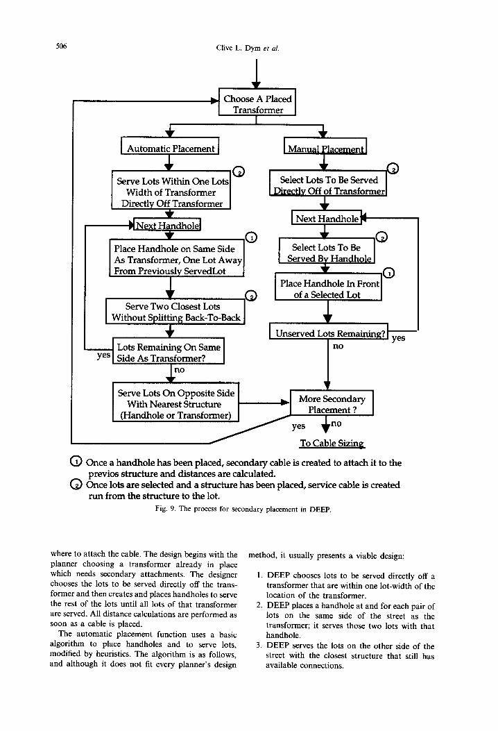
The final stage of the design is the handhole and secondary cable placement. Although it is not the most complicated part of the process, secondary placement consumes a great deal of time in plat design. Planners using the AutoCAD-based UDS system spend a significant portion of their time placing and connecting cable lines. Planners using pencil-and-paper methods spend a significant fraction of their time measuring distances and performing load calculations. It thus seemed worthwhile to improve this situation by allowing the DEEP system to identify the location(s) where cable(s) must be placed and performing the distance and load calcu- lations automatically for the planner. Although this part of the program does not utilize rule-based reasoning, it does demonstrate the power of object representation. The process for secondary placement is shown in Fig. 9, and each step is explained below.
The planner has two options for secondary equipment: manual placement by the designer or automatic placement by DEEP. Manual placement allows the planner to choose an object (e.g., a lot, handhole or transformer); from the object structure defined in Section 3.1, the system then “knows”
506 Clive L. Dym et al.
I Automati; Placement 1
* 0 Serve Lots Within One Lots
Width of Transformer Directly Off Transformer
??
Place Handhole on Same Side As Transformer, One Lot Away From Previously ServedLot
0 Serve Two Closest Lots
Without Splitting Back-To-Back +
I Lots Remaining On Same yes _ Side As Transformer?
1 Manual ylacement 1
Select Lots To Be Served
Select Lots To Be Served Bv Handhole
no
With Nearest Structure (Handhole or Transformer)
More Secondary Placement ?
To Cable Sizing
0 Once a handhole has been placed, secondary cable is created to attach it to the previos structure and distances are calculated.
0 Once lots are selected and a structure has been placed, service cable is created run from the structure to the lot.
Fig. 9. The process for secondary placement in DEEP.
where to attach the cable. The design begins with the planner choosing a transformer already in place which needs secondary attachments. The designer chooses the lots to be served directly off the trans- former and then creates and places handholes to serve the rest of the lots until all lots of that transformer are served. All distance calculations are performed as soon as a cable is placed.
The automatic placement function uses a basic algorithm to place handholes and to serve lots, modified by heuristics. The algorithm is as follows, and although it does not fit every planner’s design
method, it usually presents a viable design:
1. DEEP chooses lots to be served directly off a transformer that are within one lot-width of the location of the transformer.
2. DEEP places a handhole at and for each pair of lots on the same side of the street as the transformer; it serves those two lots with that handhole.
3. DEEP serves the lots on the other side of the street with the closest structure that still has available connections.
DEEP 507
Select Transformer With Placed Secondary
I)
+ ) Calculate Flicker and
Voltage Drop for Lots
m Flicker and Voltage Drop Within Limits?
Resize Resize Create A
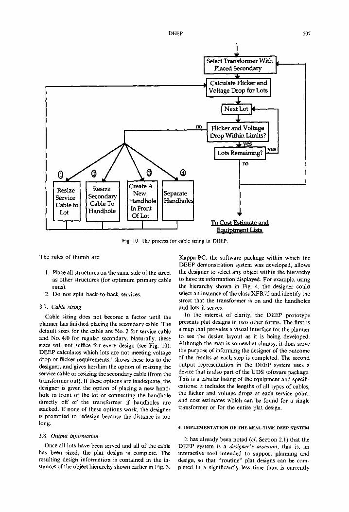
Fig. 10. The process for cable sizing in DEEP.
The rules of thumb are:
1. Place all structures on the same side of the street as other structures (for optimum primary cable runs).
2. Do not split back-to-back services.
3.7. Cable sizing
Cable sizing does not become a factor until the planner has finished placing the secondary cable. The default sizes for the cable are No. 2 for service cable and No. 4/O for regular secondary. Naturally, these sizes will not suffice for every design (see Fig. 10). DEEP calculates which lots are not meeting voltage drop or flicker requirements,’ shows these lots to the designer, and gives her/him the option of resizing the service cable or resizing the secondary cable (from the transformer out). If these options are inadequate, the designer is given the option of placing a new hand- hole in front of the lot or connecting the handhole directly off of the transformer if handholes are stacked. If none of these options work, the designer is prompted to redesign because the distance is too long.
3.8. Output information
Once all lots have been served and all of the cable has been sized, the plat design is complete. The resulting design information is contained in the in- stances of the object hierarchy shown earlier in Fig. 3.
Kappa-PC, the software package within which the DEEP demonstration system was developed, allows the designer to select any object within the hierarchy to have its information displayed. For example, using the hierarchy shown in Fig. 4, the designer could select an instance of the class XFR75 and identify the street that the transformer is on and the handholes and lots it serves.
In the interest of clarity, the DEEP prototype presents plat designs in two other forms. The first is a map that provides a visual interface for the planner to see the design layout as it is being developed. Although the map is somewhat clumsy, it does serve the purpose of informing the designer of the outcome of the results as each step is completed. The second output representation in the DEEP system uses a device that is also part of the UDS software package. This is a tabular listing of the equipment and specifi- cations; it includes the lengths of all types of cables, the flicker and voltage drops at each service point, and cost estimates which can be found for a single transformer or for the entire plat design.
4. IMPLEMENTATION OF THE REAL-TIME DEEP SYSTEM
It has already been noted (c$ Section 2.1) that the DEEP system is a designer’s assbtant, that is, an interactive tool intended to support planning and design, so that “routine” plat designs can be com- pleted in a significantly less time than is currently

508 Clive L. Dym et al.
required. Informal validation testing has shown that a customer service planner supported by DEEP com- pletes a rough design of a residential development in less than one-quarter of the time it takes to do the design “by hand”. As a result, SCE has initiated the development needed to integrate DEEP into SCE’s design system so that DEEP will more automatically (1) capture design input data from an AutoCAD layout program and (2) feed DEEP’s design results into the Utility Design System (UDS) program that, among other tasks, formulates parts lists for final designs. ’
SCE expects to realize still other gains, including: (1) freeing planners to consider multiple designs for each tract, which in turn should lead to more efficient final designs, that is, designs that are more ejicient than simply acceptable; (2) ensuring that designers adhere to all of SCE’s design parameters, thus producing more uniform and consistent designs; and (3) providing a community knowledge base* which captures and integrates the individual design ap- proaches taken by SCE’s designers and planners as they exercise DEEP.
The architecture of a prototype real-time DEEP system is shown in Fig. 11. It includes the UDS software package as the user interface through which the planner accesses (1) the basemap in the underlying AutoCAD program and (2) the knowl- edge base of the design expertise (e.g., heuristics and other design rules applied during the design process) contained in DEEP.
The major issue underlying the successful integration of DEEP with AutoCAD/UDS is the translation of the various representations used by the individual programs, from one to the other. This hard problem has been tackled successfully in other contexts (e.g., checking architectural designs for con- formance with safety and other codes4 and for providing integrated design and modeling software for civil engineering”,“). In the present context, DEEP must have its own version of the basemap of
the residential plat being designed to begin spatial reasoning. The service points for each lot and the associated geometries of the plat’s streets are required to instantiate the appropriate objects and slots in DEEP. While DEEP can access the basemap data in AutoCAD, the points and lines given in AutoCAD are simply numerical data that have no meaning (semantics) attached. The basemap in AutoCAD can be “drawn with meaning” if that basemap can trans- late its data into the same representation used by UDS (e.g., transformers, handholes, cables, etc.). When these devices or objects are created, they are stored as blocks rather than as points, lines, and curves-with each block being essentially an object or frame as identified in the context of object-oriented programming. Each UDS block contains the geometrical information about the location and shape of the subject part, and is eventually inserted into the AutoCAD maps. If a service point is ident- ified on the basemap by such a block, information about the associated street geometry can then be attached as extended data. Once these service point blocks are established within AutoCAD, DEEP can translate the information into its own object-oriented representation.
Once a plat design has been created by DEEP (within the integrated AutoCAD-DEEP-UDS system), the remaining task is the translation of that design’s specifications into a format that UDS can understand. The design results obtained by DEEP can be translated into UDS’s block structure and then inserted back into the original design drawing.
Thus, the UDS/DEEP interface would be a more powerful, intelligent and user-interactive tool than either of the respective systems provides in their current states. Planners will be able to “click” on lots in the UDS basemap and immediately assign them to a street. DEEP, utilizing its knowledge base, will make suggestions for the selected lots, choose the best transformer configuration, or even sketch out how the rest of the plat design might look if the selected
AutoCAD
UDS DEEP (KBES) +
(Semantics) Rules and 0 Obiects with
Design Layout (Geometry)
(Representation: geometry/points and lines)
Fig.
Parts (e.g., transformers) 4 Slots 1 Attributes
I
(Representation: blocks) (Representation: objects or frames)
Il. The ideal architecture of a real-time DEEP system.
DEEP 509
lots were grouped together. DEEP also could provide an instantaneous evaluation of whether voltage drop and flicker requirements were being met by the proposed design. Further, DEEP could also evaluate various designs in terms of their economics and make suggestions on how a plat design could be improved by using the order and cost sheets generated by UDS and replicated within DEEP. This approach would also allow multiple designs to be considered since, at any point, the designer could save a design or back- track to a previous step and continue on a new design path.
5. CONCLUSIONS
This paper has described the development of the DEEP design demonstration system and its current integration into SCE’s run-time design system. The system successfully emulates and extends the process that plat designers follow in terms of spatial reasoning, component selection and component configuration. The demonstration system does the intended design task-i.e., it provides direction and advice for completing a residential plat design- correctly and efficiently, perhaps the most interesting outcome is that SCE has chosen to integrate this knowledge-based designer’s assistant into its run-time computer environment for routine use by SCE’s planners and. designers.
Acknowledgements-The authors of this paper are grateful to the Southern California Edison Company who, through their joint Center of Excellence at Harvey Mudd College, have funded the DEEP research project. In addition, many thanks are due to the SCE engineers and designers who helped focus the authors on the residential plat design task and who provided the knowledge and insight into the design process that is captured in DEEP. In fact, experience indicates that experts learn a great deal about the origins and use of their knowledge, and they come to prize being chosen to have their knowledge encapsulated in an expert system. 8,9 The authors truly hope that this is the case for the SCE designers who graciously gave of their time and knowledge in the building of DEEP: Julio Arencibia, John
Cavener, Matthew Deatherage, Mike Giovanni, Danny Haberern, Gay Kohn and Mick O’Neil. The authors are also grateful to the SCE “visionaries” who are supporting the real-time integration implementation of DEEP: Jaime Amezcua, John Cavener, Randy Daffern, Tony Fung, Kirby Holte, Jim Horstman and Dave Peterson. And, finally, we are grateful to Mike Roys, HMC ‘95, who has contributed greatly to SCE’s plans for the integration of DEEP.
1.
2.
3.
4.
5.
6.
I.
8.
9.
10.
11.
REFERENCES
D. Harberern, J. Cavener, W. Schmus, J. Arencibia and M. A. Deatherage (Customer Service Department, Southern California Edison), personal communications, 15 and 24 June 1992. C. L. Dym and R. E. Levitt, Knowledge-Based Systems in Engineering, McGraw-Hill, New York, 1990. S. Mittal, C. L. Dym and M. Morjaria, “PRIDE: an expert system for the design of paper handling systems”, Computer 19(7), 1986. C. L. Dym, R. P. Henchey, E. A. Delis and S. Gonick, “A knowledge-based system for automated architec- tural code-checking”, Computer-Aided Design 20(3), 1988. Z. Sumic, S. S. Venkata and T. Pistorese, “Automated underground residential distribution design, Part I: Conceptual design”, IEEEjPES Winter Meeting, New York, 1992. Z. Sumic, S. S. Venkata and T. Pistorese, “Automated underground residential distribution design, Part II: Prototype implementation and results”, IEEEjPES Winter Meeting, New York, 1992. Anon., Distribution Design Standards Manual, Customer Service Department, Southern California Edison Company, Rosemead, CA, 1992. S. Mittal and C. L. Dym, “Knowledge acquisition from multiple experts”, AI Mag 6(2), 1985. C. L. Dym, “Issues in the design and implementation of expert systems”, Artif. Intell. Engng Design, Analysis and Manufacturing l(l), 1987. R. Fruchter. M. Clavton. H. Krawinkler. J. Kunz and P. Techolz, “Interdisciplinary Communication Medium for Collaborative Design”, in AI CIVIL-COMP 93 (edited by H. V. Topping), pp. 7-16, CIVIL-COMP Press, Edinburgh, 1993. M. Clayton, R. Fruchter, H. Krawinkler and P. Teicholz, “Interpretation Objects for Multi- disciplinary Design”, in AI in Design 94 (edited by J. Gero and F. Sudweeks), pp. 5733590, Kluwer Academic Publishers, Dordrecht, 1994.