decommissioning at fukushima-daiichi npp · decommissioning at fukushima-daiichi npp ... (october...
TRANSCRIPT

All Rights Reserved ©2015 The Tokyo Electric Power Company, Inc.
4 MAR 2014, Fukushima-Daiichi NPP (Source : Nikkei Inc.)
Decommissioning at Fukushima-Daiichi NPP
Takafumi IHARA

All Rights Reserved ©2015 The Tokyo Electric Power Company, Inc.
All Units maintain cold shutdown �
RPV bottom temp. PCV internal temp.� Fuel pool temp. �
Unit 1 ~17 ~17 ~13
Unit 2 ~21 ~22 ~30
Unit 3 ~20 ~19 ~20
Unit 4 No fuel, so monitoring not required
No fuel, so monitoring not required
~9
Values as of 11:00 on January 11, 2016
1

All Rights Reserved ©2015 The Tokyo Electric Power Company, Inc.
! About one-100 thousandth compared with the one after the accident
! Outside port are substantially below notified concentration.
36 6
36
,
1 ,
0536 -, -
36
- 1-,
36 26
36
26
6
[Regulation limit] Cesium 137: 90 Bq/L Cesium 134: 60 Bq/L
Concentration level of radioactive materials in the sea
" The concentration level has been gradually decreased
15 km off the coast of NPS (Bq/L)
Sea Water Inlet at unit 4 (Bq/L)
Discharge outlet (South) (Bq/L)
Mar 2011 Oct 2015
May 2011
Oct 2015
Apr 2011 Sep 2015

All Rights Reserved ©2015 The Tokyo Electric Power Company, Inc.
" TEPCO continuously collects information from all contractors and arrange to assure the necessary number of workers for expected works
Number of workers
3
Average worker in weekday (man/day)���������
Month
(May,&2015)&
FY&2013& FY&2014& FY&2015&

All Rights Reserved ©2015 The Tokyo Electric Power Company, Inc.
Present Status
Water Inventory Issue
Decommissioning Roadmap
Improvement on work environment
Roles and responsibility among organizations for decommissioning
Main Contents
4

All Rights Reserved ©2015 The Tokyo Electric Power Company, Inc.
Present Status
Water Inventory Issue
Decommissioning Roadmap
Improvement on work environment
Roles and responsibility among organizations for decommissioning
5

All Rights Reserved ©2015 The Tokyo Electric Power Company, Inc.
Progress Made at 1F Unit 1
Remote-operated boat and robot identified leakage locations in torus room
Reactor Building (3/15/2011)
Reactor Building Cover (installed in Oct. 2011)
Torus Room (5/27/2014) Torus Room (11/13/2013)
6

All Rights Reserved ©2015 The Tokyo Electric Power Company, Inc.
Progress Made at 1F Unit 1 (cont’d)
Robot identified leakage from expansion joint of vacuum breaker piping (5/27/2014)
7

All Rights Reserved ©2015 The Tokyo Electric Power Company, Inc.
Progress Made at 1F Unit 1 (cont’d)
Reactor building are being dismantled in preparation for fuel removal
8

All Rights Reserved ©2015 The Tokyo Electric Power Company, Inc.
(Ref) Procedure of dismantling Unit1 building cover
■Mitigation measures against dust dispersion are being conducted while building cover is dismantled. ■All the roof panels have been dismantled (5 Oct. 2015)
FY 2016 FY 2017 FY 2015 FY 2014
Rubble removal
Installation of fuel handling support etc.
Dismantling building cover
9

All Rights Reserved ©2015 The Tokyo Electric Power Company, Inc.
Progress Made at 1F Unit 1 (cont’d)
Conditions of the top of operating floor Reactor building cover removal
(October 2015)
" Building cover removal is in progress taking measures against dust stirring and of decontamination and shielding on the floor
" Many rubbles on the operating floor will be removed " Finally, the deck and fuel handling machine will be installed
Overview of refueling level (June 2012)

All Rights Reserved ©2015 The Tokyo Electric Power Company, Inc.
Rubble
Ceiling crane
Picture 1
Picture 2
Picture 3
Surface of fuel spent pool
Cover of reactor well
Ceiling crane
Cover of reactor well
Progress Made at 1F Unit 1 (cont’d)

All Rights Reserved ©2015 The Tokyo Electric Power Company, Inc.
Progress Made at 1F Unit 2
Gamma Camera Image of Refueling Floor (2/21/2013)
Blow-out Panel Closed (3/11/2013)
Steam Coming Out From Blow-out Panel (4/10/2011)
Video images obtained inside primary containment 12

All Rights Reserved ©2015 The Tokyo Electric Power Company, Inc.
Progress Made at 1F Unit 2 (cont’d)
Robot retrieved core samples from refueling
floor (3/21-22/2014) 13

All Rights Reserved ©2015 The Tokyo Electric Power Company, Inc.
Progress Made at 1F Unit 3
Spent Fuel Pool (2/14~18/2013)
Rubble Removal in Progress (5/29/2013)
Crippled Reactor Building (3/15/2011)
Robot found leakage location in reactor building 14

All Rights Reserved ©2015 The Tokyo Electric Power Company, Inc.
Progress Made at 1F Unit 3 (cont’d)
Rubble in spent fuel pool being removed by remote operation
15

All Rights Reserved ©2015 The Tokyo Electric Power Company, Inc.
Before large debris removal (March 24, 2011)
N
After removal of large debris
N
(April 19, 2014)
Rubble removal toward fuel removal from SFP in Unit 3 (1/2)
Installation of fuel removal cover and fuel handling facility planned Due to high radiation levels, dose reduction measures must be carried out safely and steadily with remote-controlled heavy machinery.
Current
Status tasks
" ALARA is kept in the Decontamination and shielding works " The taget of dose exposure for fuel removal is less than 1mSv/h
16

All Rights Reserved ©2015 The Tokyo Electric Power Company, Inc.
Decontamination work completed
" The dose rate on the Unit 3 refueling floor is high " Decontamination work is being conducted with remote-
controlled heavy machinery and decontamination devices.
Rubble collection device Suction device
Cutting device
Used for the collection of small debris
Used for suction removal of small debris and dust, etc.
Used for cutting the surfaces of concrete Decontamination work partially
completed
Unit 3 refueling floor
Decontamination toward fuel removal from SFP in Unit 3 (2/2)
17

All Rights Reserved ©2015 The Tokyo Electric Power Company, Inc.
(Ref) Dose difference between Unit 4 and 3
Measured : ~February 2014
18
All Rights Reserved ©2015 The Tokyo Electric Power Company, Inc.
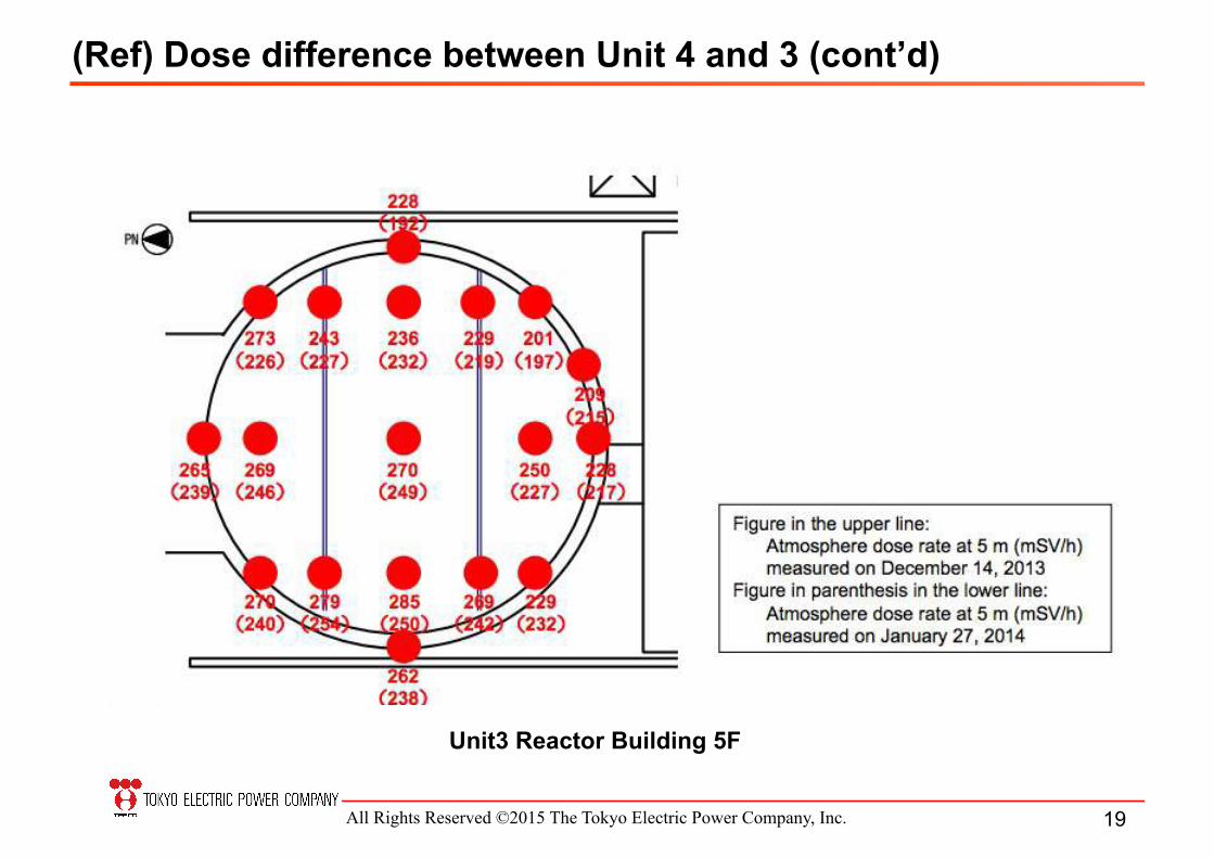
(Ref) Dose difference between Unit 4 and 3 (cont’d)
19
Unit3 Reactor Building 5F

All Rights Reserved ©2015 The Tokyo Electric Power Company, Inc.
Current Condition (May 2014)
�
Photo Damage to concrete surface
Photo Condition of north side of R/B
Photos Photo
(Ref) Unit 3 Refueling Floor (Significant Damage Sustained)
20

All Rights Reserved ©2015 The Tokyo Electric Power Company, Inc.
Preparation Status for Fuel Removal Cover at Unit 3
! Cover components including steel frame and girder were made and transported to the Onahama Port, more than 50 km away from 1F.
! Once assembled there in order to confirm working procedure ! Module partially assembled there will be transported to reduce
working hours and occupational dose at site
Removal of Fuel Handling Machine from SFP
(Aug. 2015)
Assembling work at Onahama Port (October 2014)
Fuel removing cover (Image)
Roof Crane
Fuel Handling Machine
Cover for removing fuels

All Rights Reserved ©2015 The Tokyo Electric Power Company, Inc.
����
�������
����
������
����
���������
���������
����
�������
����
������
����
���������
���������
Concrete wall
Progress Made at 1F Unit 4
Water Injection by Concrete Pumper (3/22/2011)
Fuel Removal from SFP (11/18/2013~)
Spent Fuel Pool Structure Reinforced
(7/30/2011)
S t e e l Pillars
22

All Rights Reserved ©2015 The Tokyo Electric Power Company, Inc.
On-site transporting cask
Crane
Fuel removal from SFP in Unit 4
�������
������� ����
�������
On-site transport
Spent fuel pool (SFP)
Fuel removal cover
Cask pit Ensuring
empty space.
Fuel handling machine (FHM)
Cask pit
• Fuels have been removed since November 18, 2013. • 1533 fuels was stored inside SFP at the time of starting fuel
removal.
Common pool (on site)
23

All Rights Reserved ©2015 The Tokyo Electric Power Company, Inc.
Fuel removal from SFP in Unit 4 (cont’d)
Status on Sep.22,2011 Removal of PCV head (July 2012)
Construction of cover flame (Jan. ~ May 2013)
Complete the Fuel removal facility cover (Oct. 2013)
Fuel removal work started (Nov. 18. 2013)
Rubble removal on 5th floor of R/B (Mar. 2012)
" Construction period: 11m (From steel flame erection to commence of Fuel Removal)
" Gross weight of newly installed facility: approx. 4,900 ton
24

All Rights Reserved ©2015 The Tokyo Electric Power Company, Inc.
Present Status
Water Inventory Issue
Decommissioning Roadmap
Improvement on work environment
Roles and responsibility among organizations for decommissioning
25

All Rights Reserved ©2015 The Tokyo Electric Power Company, Inc.
Inflow Approx. 300m3/day
(evaluation value)
Turbine bldg.
Ground water
Contaminated water
Cesium absorption
Mobile strontium removal equipment, etc.
KURION SARRY
From well-points etc. Approx. 100m3/day
Approx. 720m3/day
Sr removal function added
Treated water
Remove 62 radioactive substances except for
tritium
Reactor cooling waterApprox. 320m3/day
, ., 0 539 000 1st Oct.
Sr treated water
Reduced risks
, ., 0 155 000 1st Oct.
RO Concentrated salt water
, .
1st Oct.
Approx. 400m3/dayDesalination
Circulating-Water Core Cooling System at 1F " All Reactor Cores stably cooled " Contaminated water increases daily
Multi-nuclide removal equipment
(ALPS)

All Rights Reserved ©2015 The Tokyo Electric Power Company, Inc.
3 policies for contaminated water
Site paving
permeable layer Low-permeable layer permeable layer Low-permeable layer
Sub-drain Groundwater level
Sea level
Land-side impermeable wall Land-side impermeable wall
Rain
Trench Sub-drain
Groundwater Bypass Water
Treatment
Sea-side impermeable wall
Policy 1. Remove source of contamination
Policy 2. Isolating groundwater from contamination sources
Policy 3. Preventing leakage of contaminated water
Clean up contaminated water with Multi-nuclide removal equipment (ALPS) Remove contaminated water in trenches (Underground tunnel with piping)
Pumping up groundwater through groundwater bypasses Pumping up groundwater through wells near buildings Installation of frozen-soil impermeable wall on the land side Paving of site to curb permeation of rainwater into soil
Ground improved with water glass Installation of impermeable walls on the sea side Augmentation of tanks (replacement with welded tanks, etc.)

All Rights Reserved ©2015 The Tokyo Electric Power Company, Inc. 28
ISOLATE&WATER&FROM&CONTAMINATION&&
Groundwater Bypass
Pumps collect groundwater flowing
towards the damaged reactor buildings and
divert it safely to the sea
GROUNDWATER&
300-350 Tons/day&pumped&up&&&
50-80 Tons/day&esGmated&amount&of&water&reduced&&flowing&into&reactor&buildings&

All Rights Reserved ©2015 The Tokyo Electric Power Company, Inc.
Landside Impermeable Wall “Ice Wall”
! Freezing operation in trial commenced on April 30, 2015 ! 70,000 m3 of soil to be frozen ! Freezer plant: 230 kW x 30 units
29

All Rights Reserved ©2015 The Tokyo Electric Power Company, Inc. 30
ISOLATE&WATER&FROM&CONTAMINATION&&
Landside Impermeable Wall “Ice Wall” (cont’d) �
Block groundwater from entering the units and becoming contaminated
1,545 VerGcal&pipes&delivering&soilTfreezing&coolant&
1.5km Long&
PROGRESSION)OF)SOIL)FREEZING)(Begins)March,)2015))

All Rights Reserved ©2015 The Tokyo Electric Power Company, Inc.
Sub-Drain System
! Operation commenced on September 3, 2015 ! Enable active control of groundwater level around the buildings
31
Permeable Layer Low Permeable Layer
Low permeable Layer
Pump-up well
Groundwater level
Permeable Layer
Pump-up Pump-up
Reactor Building
Turbine Building
Sub drain
Isolating water from the contamination source
Sea level
Ice Wall
Groundwater Bypass
All Rights Reserved ©2015 The Tokyo Electric Power Company, Inc.
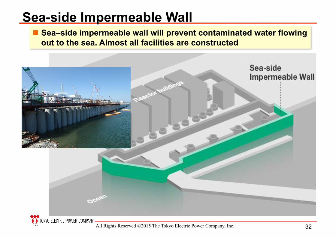
Sea-side Impermeable Wall " Sea–side impermeable wall will prevent contaminated water flowing
out to the sea. Almost all facilities are constructed
32

All Rights Reserved ©2015 The Tokyo Electric Power Company, Inc.
Contaminated Water in Underground Trench
The Removal of High-Concentrated Contaminated water in underground trenches has been completed
33
All Rights Reserved ©2015 The Tokyo Electric Power Company, Inc.
3 1 IF FFE D E FE
3 )-‐‑‒3 ( I MFD FE D E I
23 C B FFE D E M
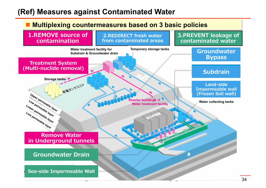
Reactor buildings # �Water treatment facility �
Storage tanks �
F E M ) E
I -‐‑‒DG D C CC
D E NI D C E C DFL C
3 DFLE E F E EE CI
F E MNG II
E
. E I-‐‑‒DG D C M CC FO E F C M CC
Water collecting tanks �
Temporary storage tanks�Water treatment facility for Subdrain & Groundwater drain�
(Ref) Measures against Contaminated Water
" Multiplexing countermeasures based on 3 basic policies
34
All Rights Reserved ©2015 The Tokyo Electric Power Company, Inc.
Present Status
Water Inventory Issue
Decommissioning Roadmap
Improvement on work environment
Roles and responsibility among organizations for decommissioning
35

All Rights Reserved ©2015 The Tokyo Electric Power Company, Inc.
Mid- to Long-Term Road Map Towards Decommissioning
Phase-1 Phase-2 Phase-3
Begin removal of fuels from spent fuel
pools
Cold Shutdown Condition Achieved (Dec., 2011)
Within 2 years
Within 10 years
30 to 40 years
Begin removal of fuel debris
Complete decommissioning
Global collaboration vitally important to tackle this unprecedented undertaking
Common pool
Crane F u e l Handling Machine
Unit 4 Nov. 2013
Stop Leakage Flood PCV and Remove Fuel Debris
Today
36

All Rights Reserved ©2015 The Tokyo Electric Power Company, Inc.
Fuel Debris���Submersion
Access �������Top Challenge�����Water tightness, Seismic integrity
Partial submersion
����������Top �
Partial submersion
����������Side �Radioactive dust dispersion,
Radiation shielding
Toward fuel debris removal " Examination of fuel debris retrieval methods in consideration of
water submersion cases

All Rights Reserved ©2015 The Tokyo Electric Power Company, Inc.
! Fuel debris from Fukushima site will be analyzed with grove box and manipulator in shielded facilities.
! In 2013, the terms and conditions for the location of the facility were decided and the operation is scheduled to start in 2018.
②RadioacGve&Material&Analysis&①MockTup&TesGng&
! Provide such real size equipment as is in NPP to examine the applicability of the remote control equipment and to train operators.
! Ground breaking ceremony was held on 26 Sep 2014 and the facility started its partial operation in October 2015.
" To establish technical basis, JAEA will build below with supplementary budget of 2012. Remote-control and Device Development Facility (Mock-up Testing Facility) Radioactive Material Analysis and Research Facility
" These facilities will be managed in a manner that is easily accessible by domestic and international researchers in various fields.
R&D toward fuel debris removal

All Rights Reserved ©2015 The Tokyo Electric Power Company, Inc.
Highly pressurized water decontamination device
(Hitachi-GE) Suction and blast decontamination device MHI
Dry ice blast decontamination device (Toshiba)
Investigation Contamination status inside building with robots, leakage points of PCV and status of fuel debris etc. are currently being conducted.
[Main result from investigation] 1. Water leak was identified at the
reactor of Unit 1 in November, 2013. 2. M e a s u r i n g w a t e r l e v e l w a s
successfully conducted at the bottom part of RPV in Unit 2 in January, 2014.
1. 2.
R&D toward fuel debris removal Decontamination Robots for lower place on 1st floor of the building have been tested since FY 2013.
Robots have been tested for higher place since FY 2014 and since FY 2015 for upper floor
39

All Rights Reserved ©2015 The Tokyo Electric Power Company, Inc.
Present Status
Water Inventory Issue
Decommissioning Roadmap
Improvement on work environment
Roles and responsibility among organizations for decommissioning
40

All Rights Reserved ©2015 The Tokyo Electric Power Company, Inc.
FullTface&respirator&
Surgical&Mask&
Dust&ProtecGve&Mask&
HalfTface&Respirator&
Expanding area without full face mask " Full-face respirator required in all site
areas just after the accident " Currently, full-face respirators are not
required except for works in the buildings and related to contaminated water �
41

All Rights Reserved ©2015 The Tokyo Electric Power Company, Inc.
Improving welfare facilities
Large resting facility Meal Service Center
" A large on-site resting area completed in May 2015 for approximately 1,200 workers)
" New office building was completed in October 2014 (for approximately 1200 TEPCO/FDEC employees) " Fukushima Revitalization Meal Service Center commenced to
provide warm lunch to working people onsite in June 2015 Increase of local employment as well as use of local products
42

All Rights Reserved ©2015 The Tokyo Electric Power Company, Inc.
" The system visualizing the real time dose rate is in place by deploying 20 dose rate detectors on site, increasing to 70 monitors in the future.
" The display of this system should be placed where workers can easily access.
" Continuous dust monitoring data will be added to the system in the future.
Visualization of dose rate

All Rights Reserved ©2015 The Tokyo Electric Power Company, Inc.
■ Debris removal on seaside area ■ Sort out in Tank Area Before After Before After
In front of Unit 2 T/B
Inside of centralized radioactive waste treatment building (RW/B)
In front of Unit 4 T/B
■ Pavement at coastal area Before After
On Sea side area in Units 3 and 4
Improvements on work environment – Field improvement
44

All Rights Reserved ©2015 The Tokyo Electric Power Company, Inc.
Present Status
Water Inventory Issue
Decommissioning Roadmap
Improvement on work environment
Roles and responsibility among organizations for decommissioning
45

All Rights Reserved ©2015 The Tokyo Electric Power Company, Inc.
Establishment of FDEC (Since April 1, 2014)
46

All Rights Reserved ©2015 The Tokyo Electric Power Company, Inc.
Establishment of FDEC (Since April 1, 2014)
47
All Rights Reserved ©2015 The Tokyo Electric Power Company, Inc.
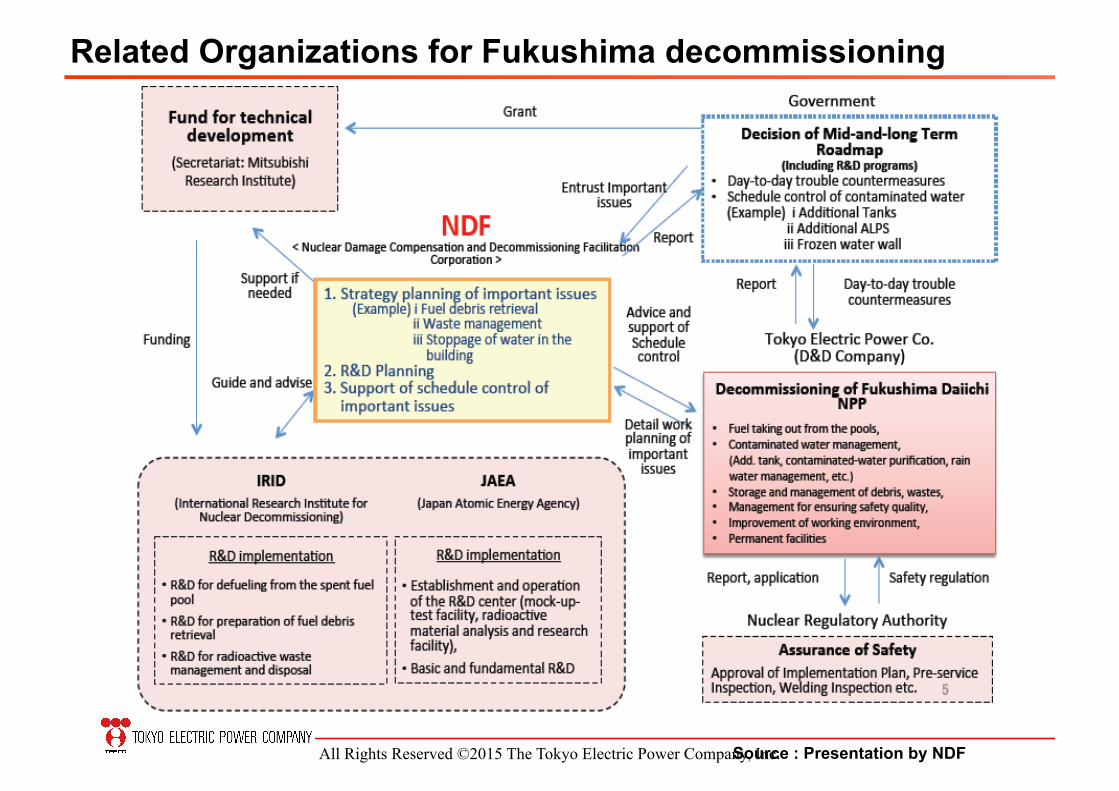
Related Organizations for Fukushima decommissioning
Source : Presentation by NDF

All Rights Reserved ©2015 The Tokyo Electric Power Company, Inc.
Recent Findings
49

All Rights Reserved ©2015 The Tokyo Electric Power Company, Inc.
Muon Technology for Fuel Debris Identification
http://www.tepco.co.jp/en/nu/fukushima-np/handouts/2015/images/handouts_150319_01-e.pdf
50
Expecting result
! The higher the density is, the more muon are absorbed
! Permeation method for 2D images, but the use of two detectors makes possible to create 3D images by combining the data
! The large absorbers in SFP, which were expected to be seen, were verified, but not verified inside the reactor.

All Rights Reserved ©2015 The Tokyo Electric Power Company, Inc.
3 Phases Investigation B1 : Done B2 : Planned (in FY2015) Pedestal : Planned (2016~2017)
http://www.tepco.co.jp/en/nu/fukushima-np/handouts/2015/images/handouts_150430_04-e.pdf
Shape-Shifting Robots Obtained Crucial Intelligence on Unit1 Inside PCV
51

All Rights Reserved ©2015 The Tokyo Electric Power Company, Inc.
X-6 Penetration CRD exchanging
rail Entrance to pedestal Personnel
airlock
CRD
Platform
H
W
(Source : TOSHIBA) The other Robot is ready for Probe at Unit 2 Pedestal
CCD Camera ×2 LED
Change
Shape
Boom (enabling angle change)
RPV
52
(Source : TOSHIBA)

All Rights Reserved ©2015 The Tokyo Electric Power Company, Inc.
Thank you for your attention
57

All Rights Reserved ©2015 The Tokyo Electric Power Company, Inc.
Reference
58

All Rights Reserved ©2015 The Tokyo Electric Power Company, Inc.
Fukushima-Daiichi NPP Map
59