decode 1.1 decoder, encoders and displays ©paul godin updated aug 2013
TRANSCRIPT
Decode 1.1
Decoder, Encoders and Displays
©Paul GodinUpdated Aug 2013
Decode 1.2
Decoders
Decode 1.3
Decoder
A decoder receives one binary value or state and converts it to another value or state.
Some decoders accept an input binary value or number and enable a single output pin based on that value or number (such as a “3-to-8 decoder”)
Some decoders provide a full conversion of the input to an output (such as a “BCD to a 7-segment display”)
Basic decoders are comprised of combinational logic.

Decode 1.4
Output Select Decoders
Decode 1.5
Output Select Decoders
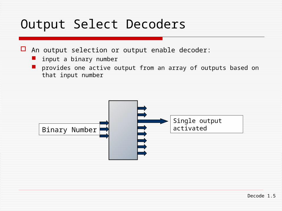
An output selection or output enable decoder: input a binary number provides one active output from an array of outputs based on that
input number
Single output activated
Binary Number
Decode 1.6
Output Select/Enable Decoders
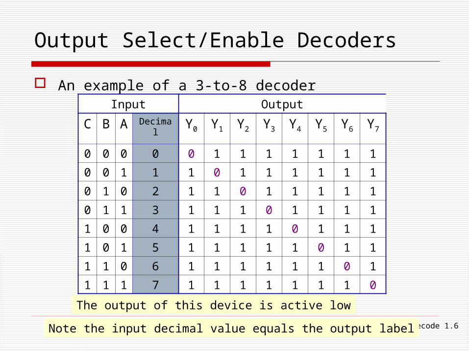
An example of a 3-to-8 decoderInput Output
C B A Decimal
Y0 Y1 Y2 Y3 Y4 Y5 Y6 Y7
0 0 0 0 0 1 1 1 1 1 1 1
0 0 1 1 1 0 1 1 1 1 1 1
0 1 0 2 1 1 0 1 1 1 1 1
0 1 1 3 1 1 1 0 1 1 1 1
1 0 0 4 1 1 1 1 0 1 1 1
1 0 1 5 1 1 1 1 1 0 1 1
1 1 0 6 1 1 1 1 1 1 0 1
1 1 1 7 1 1 1 1 1 1 1 0
The output of this device is active low
Note the input decimal value equals the output label
Decode 1.7
Application of a Decoder
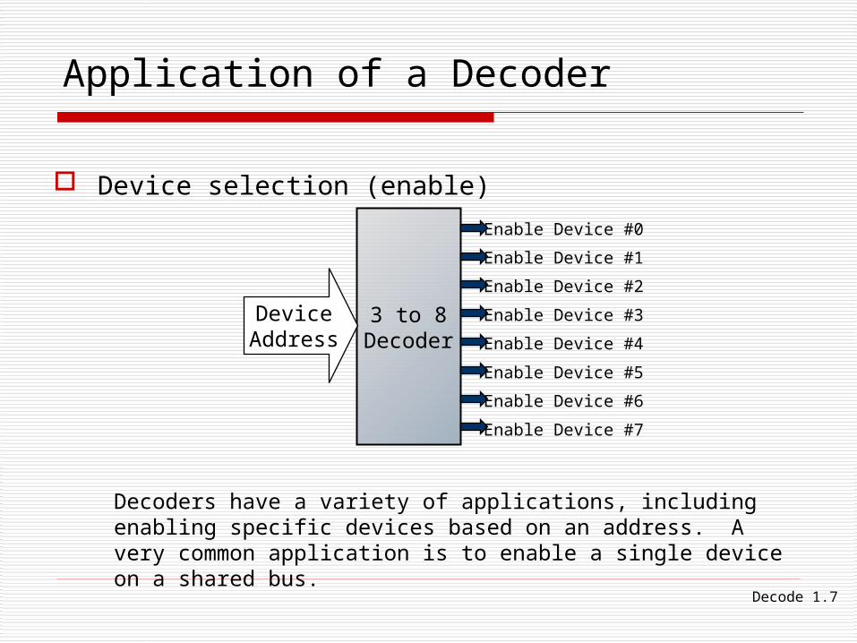
Device selection (enable)
3 to 8Decoder
DeviceAddress
Enable Device #0
Enable Device #1
Enable Device #2
Enable Device #3
Enable Device #4
Enable Device #5
Enable Device #6
Enable Device #7
Decoders have a variety of applications, including enabling specific devices based on an address. A very common application is to enable a single device on a shared bus.
Decode 1.8
Decoders
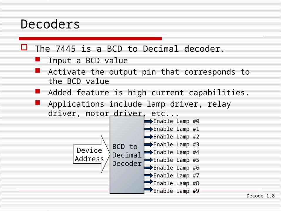
The 7445 is a BCD to Decimal decoder. Input a BCD value Activate the output pin that corresponds to the BCD
value Added feature is high current capabilities. Applications include lamp driver, relay driver, motor
driver, etc...
BCD to DecimalDecoder
DeviceAddress
Enable Lamp #0
Enable Lamp #1
Enable Lamp #2
Enable Lamp #3
Enable Lamp #4
Enable Lamp #5
Enable Lamp #6
Enable Lamp #7
Enable Lamp #8
Enable Lamp #9
Decode 1.9
Exercise – In Class
Look up the 74LS42 specification sheet and explain its operation.
Look up the 74139 and the 74138 specification sheets and explain the additional control inputs.
Design a 2-to-4 decoder.
Using EWB, connect a counter to a decoder to enable devices in sequence.
Decode 1.10
Encoders
Decode 1.11
Encoders
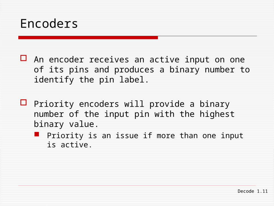
An encoder receives an active input on one of its pins and produces a binary number to identify the pin label.
Priority encoders will provide a binary number of the input pin with the highest binary value. Priority is an issue if more than one input is active.
Decode 1.12
Priority Encoder
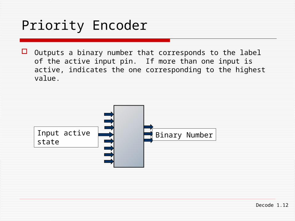
Outputs a binary number that corresponds to the label of the active input pin. If more than one input is active, indicates the one corresponding to the highest value.
Input active state Binary Number
Decode 1.13
8-to-3 Priority Encoder
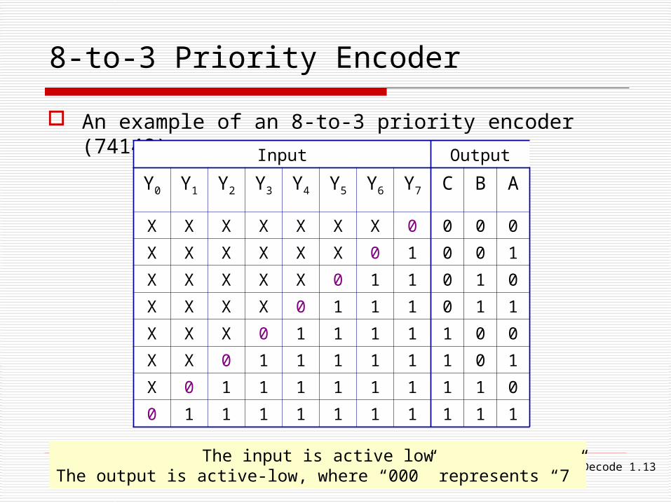
An example of an 8-to-3 priority encoder (74148)
Input Output
Y0 Y1 Y2 Y3 Y4 Y5 Y6 Y7 C B A
X X X X X X X 0 0 0 0
X X X X X X 0 1 0 0 1
X X X X X 0 1 1 0 1 0
X X X X 0 1 1 1 0 1 1
X X X 0 1 1 1 1 1 0 0
X X 0 1 1 1 1 1 1 0 1
X 0 1 1 1 1 1 1 1 1 0
0 1 1 1 1 1 1 1 1 1 1
The input is active lowThe output is active-low, where “000” represents “7”
Decode 1.14
Exercise – In Class
Look up the 74LS148 specification sheet and explain its operation.
Design a 4-to-2 encoder.
Discuss a keyboard encoder.

Decode 1.15
LEDs and Displays
Decode 1.16
LEDs
Light Emitting Diodes are common in digital electronics circuits because: Require relatively little current Generate very little heat Sufficient amount of light for most applications (indicators,
illuminators) May not require additional support circuitry Inexpensive Small in size Variety of colors Long life Rugged and vibration resistance Variety of shapes and configurations Actively being improved and developed in industry
Decode 1.17
LED
LEDs are diodes designed to emit light in the visible or in the non-visible spectrums.
The electrical properties of LEDs are: Current can flow in one direction only. Have a voltage drop not related to resistance (VF).
They require an external resistor to limit current.
Caution: Some LEDs are bright enough to damage eyesight, and some get very hot.
Decode 1.18
LED diagrams
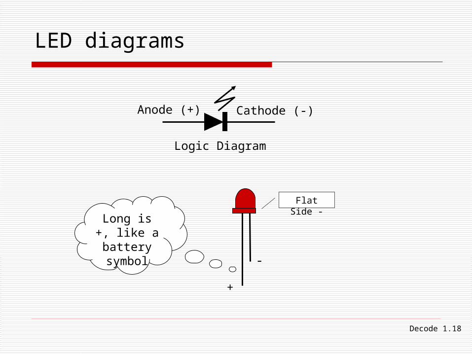
Logic Diagram
Anode (+) Cathode (-)
+
-
Flat Side -
Long is +, like a
battery symbol
Decode 1.19
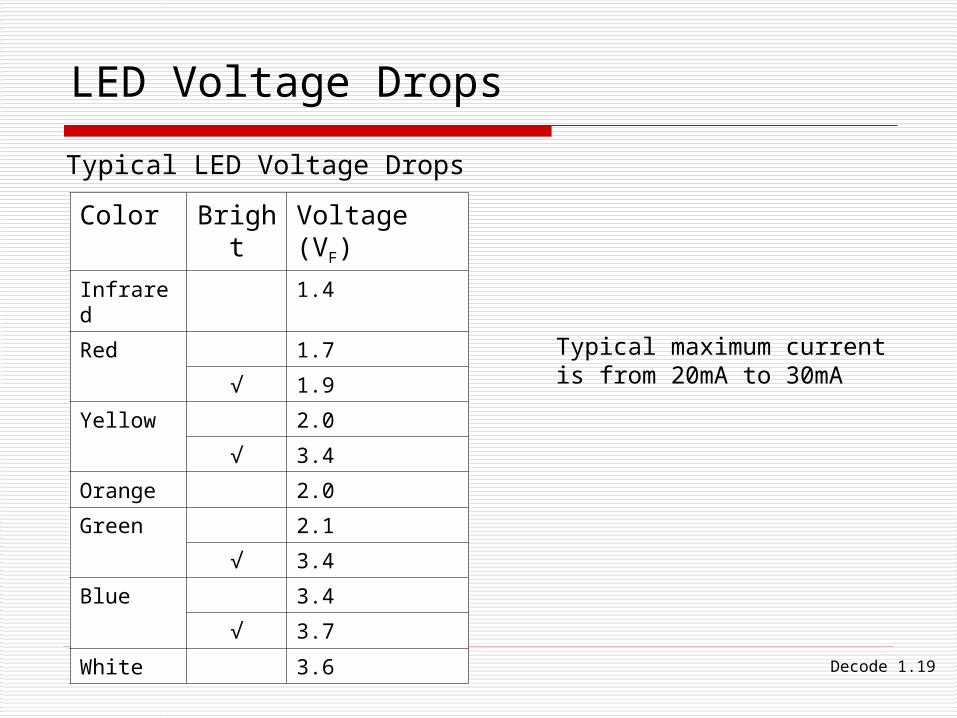
LED Voltage Drops
Typical LED Voltage Drops
Color Bright Voltage (VF)
Infrared 1.4
Red 1.7
√ 1.9
Yellow 2.0
√ 3.4
Orange 2.0
Green 2.1
√ 3.4
Blue 3.4
√ 3.7
White 3.6
Typical maximum current is from 20mA to 30mA
Decode 1.20
Calculating Series Resistor Values
Apply basic Ohm’s law to calculate resistor voltage.
Subtract the VF of the LED from the supply voltage.
Decode 1.21
LED Current and Logic Gates
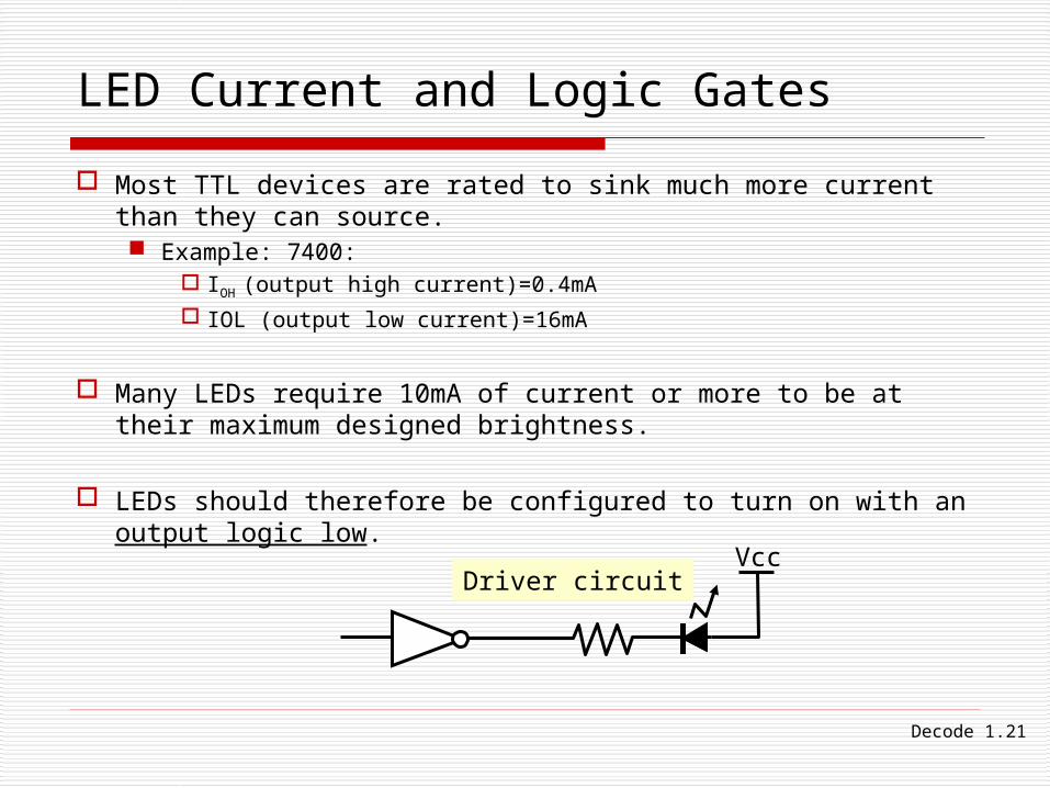
Most TTL devices are rated to sink much more current than they can source. Example: 7400:
IOH (output high current)=0.4mA IOL (output low current)=16mA
Many LEDs require 10mA of current or more to be at their maximum designed brightness.
LEDs should therefore be configured to turn on with an output logic low.
VccDriver circuit
Decode 1.22
LED Testing
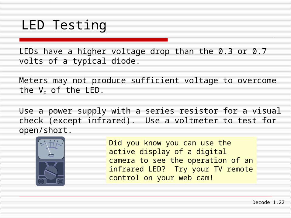
LEDs have a higher voltage drop than the 0.3 or 0.7 volts of a typical diode.
Meters may not produce sufficient voltage to overcome the VF of the LED.
Use a power supply with a series resistor for a visual check (except infrared). Use a voltmeter to test for open/short.
Did you know you can use the active display of a digital camera to see the operation of an infrared LED? Try your TV remote control on your web cam!
Decode 1.23
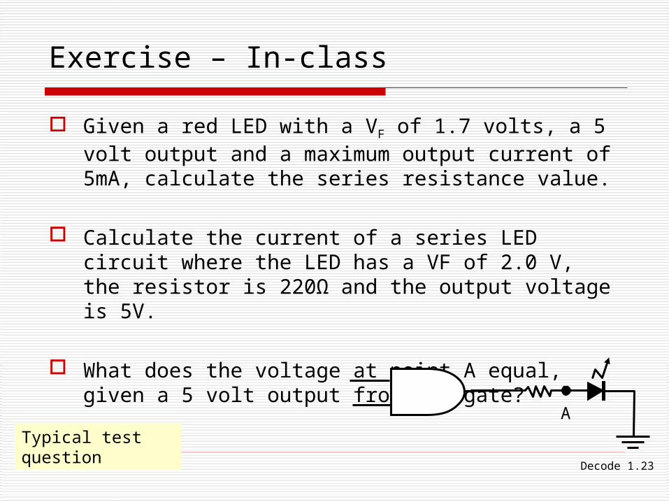
Exercise – In-class
Given a red LED with a VF of 1.7 volts, a 5 volt output and a maximum output current of 5mA, calculate the series resistance value.
Calculate the current of a series LED circuit where the LED has a VF of 2.0 V, the resistor is 220Ω and the output voltage is 5V.
What does the voltage at point A equal, given a 5 volt output from the gate?
A
Typical test question
Decode 1.24
Decoders – Logic Conversion
Decode 1.25
7-Segment Displays
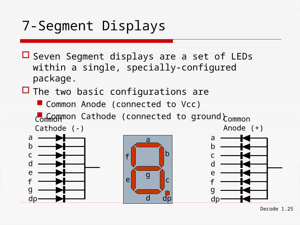
Seven Segment displays are a set of LEDs within a single, specially-configured package.
The two basic configurations are Common Anode (connected to Vcc) Common Cathode (connected to ground)
cba
defgdp
cba
defgdp
c
b
a
d
e
f
g
dp
CommonCathode (-)
CommonAnode (+)
Decode 1.26
Decoders – Logic Conversion
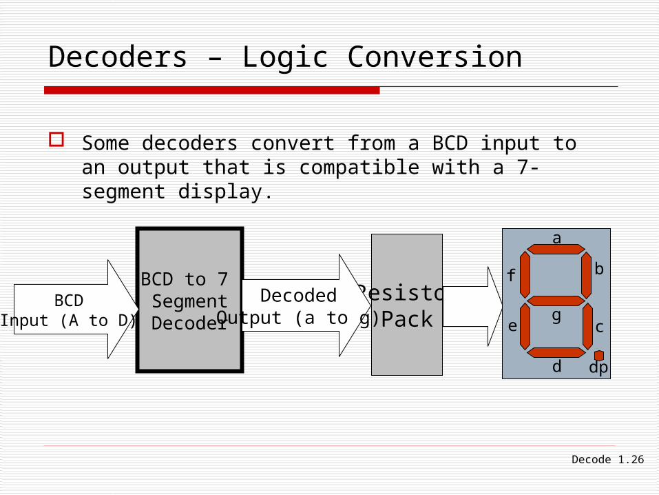
Some decoders convert from a BCD input to an output that is compatible with a 7-segment display.
BCD to 7 SegmentDecoder
BCDInput (A to D)
ResistorPack
DecodedOutput (a to g) c
b
a
d
e
f
g
dp
Decode 1.27
Display Drivers
Display drivers include the 7447 and the 4518. All share similar characteristics: Input a BCD value (A, B, C and D). The LSB is A. Output segments a, b, c, d, e, f and g. May have other features such as:
LT (Lamp Test). If active makes all outputs “on”, to test the LEDs
Enable/disable output Memory capabilities
Decode 1.28
Display Drivers
BI/RBO and RBI: Ripple Blanking Input or Output Ripple Blanking refers to making displays blank out
(nothing displayed) if their value is zero and they either precede or follow a non-zero value.
Example: The value 034.250 would have the first and the last value 0 blanked, appearing as 34.25
Dealing with Blanking Read the specification sheet for more details Leave disconnected if not using ripple blanking

Decode 1.29
BCD to 7-Segment Decoder
Other issues:
The decoder’s active output (active high or active low) needs to match the display.
There must be a resistor to limit current for each segment. The LEDs in 7-segment displays are especially sensitive to damage from too much current.
CPLD outputs are not capable of driving much current. Design for active low output if connecting LEDs to outputs without a driver.
EWB seems to have trouble with the non-decoded display. Best to use the decoded display.

Decode 1.30
Questions
On a 7-segment display, why not use a single resistor at the common to limit current for all LEDs?
What is the active output of the 7447 and the 4511?
The following is known as a ½ display. What are some applications for ½ displays?
c
b
dp

Decode 1.31©Paul R. Godinprgodin°@ gmail.com
END