decay of mhd waves by phase mixing
TRANSCRIPT
Z. Physik 261,217--236 (1973) �9 by Springer-Verlag 1973
Decay of MHD Waves by Phase Mixing II . The The ta -P inch in Cyl indr ical G e o m e t r y
W. Grossmann and J. Tataronis*
Max-Planck-Institut ftir Plasmaphysik, Euratom Association*e, Garching bei Mtinchen, Germany
Received March 13, 1973
The dispersion relation for stable waves in ideal MHD plasmas with diffuse profiles has been calculated. The non-uniformity in the density and magnetic field profiles gives rise to a very strong damping. Phase mixing is the mechanism responsible for the damping and can be seen to occur due to the presence of the continuous spectrum of the MHD equations of motion. The special case of the linear 0-pinch is examined in detail. In particular, damping coefficients for torsional Alfv6n waves are computed which agree very well with a rather wide range of experimental findings.
I. Introduction
The subject of the present paper concerns the propagation of Alfv6n waves in theta-pinch like plasma configurations. By theta-pinch like is meant an axially symmetric configuration where the plasma density and pressure and the magnetic fields do not depend on the axial coordinate. The majority of real laboratory pinch plasma experiments (theta, screw and z-pinch) fulfill this definition. Motivation for the present work is found by considering presently planned dynamical [1, 2] and feed back [3] stabilization schemes intended for toroidally theta-pinch like plasma containment systems. These dynamical schemes attempt essentially to overcome M H D instabilities by applying counter-acting forces where necessary after the appearance of an instability has been detected by, for example, an optical sensing system. If, upon the application of either oscillating or constant correcting forces, signals or waves propagate away from the source and interfere at another sensing position then the stabilizing system may become over-reactive and actually incite in- stabilities. The propagating waves could be interpreted by the sensing system as an instability. Of course, the wave signal would appear as a convective instability to the sensing system. I t is thus of great interest to
* Present Address: Courant Institute of Mathematical Sciences, New York University, New York, N.Y., USA. ** This work was performed as part of the joint research program between the Institut for Plasmaphysik, Garching, and Euratom.
218 W. Grossmann and J. Tataronis:
understand the manner in which disturbances of high beta plasma columns propagate as waves in the plasma. In this respect one recalls that from the date of the first theta-pinch experiments many experi- mentors have claimed that the experimentally useful time of observance of good plasma behaviour is limited by the time it takes for an Alfv6n wave to propagate in from the ends of the device.
Borrowing the results, in advance, from the previous paper (I) we would expect that the propagation of, for example, Alfv6n waves in such high beta plasmas are heavily damped due to phase mixing. It should be mentioned that the Alfv6n velocity for usual non-uniform high beta plasmas varies from something approaching the thermal velocity in the center of the column to that approaching the velocity of light in the regions of extremely low density. Indeed we show in this paper that due to the presence of a diffuse plasma profile Alfv6n waves are very heavily damped. As shown in Section IV, there are a sufficient number of experimental observations to support the theoretical findings of the present investigation.
We present now the calculation of the dispersion relation for the simple theta-pinch. The theta-pinch is a very useful test bed for the present theory of phase mixing in high beta columns since a number of more complex experimental situations can be considered as a slight deviation away from a basic theta-pinch plasma configuration; for example, screw pinches with low rotational transform and high beta stellarator plasmas. In the following we are interested mainly in the torsional Alfv6n wave. For this wave it is sufficient to study only in- compressible perturbations of a plasma. Magneto-acoustic waves are thus excluded from the present treatment; they are the subject of a forthcoming investigation.
II. The Theta-Pinch Dispersion Relation The theta-pinch plasma as envisioned here is assumed to be an
infinitely long axially symmetric plasma column contained by an axial magnetic field and surrounded by a cylindrical conducting wall. The plasma equilibrium properties are assumed to be independent of the axial coordinate z and vary strongly in the r direction. The equilibrium of the theta-pinch plasma is described by
P(O q B~(r) - B~(R), (1) 2po 2#0
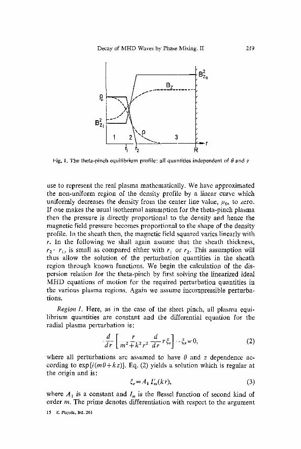
where p is the plasma pressure and B~ (R) represents the axial magnetic field evaluated at the wall radius R. In Fig. 1 are presented typical density and magnetic field profiles as found in laboratory theta-pinch plasmas along with a schematic of the approximation which we shall
Decay of MHD Waves by Phase Mixing. II 219
B 2 Zi
B 2 Zo ~ 1 1 ~ . ~ . . . . L~- Z - . . . . . . .
@-,, 3 - - - - r i i
i~ r 2 R
Fig. 1. The theta-pinch equilibrium profile: all quantities independent of 0 and z
use to represent the real plasma mathematically. We have approximated the non-uniform region of the density profile by a linear curve which uniformly decreases the density from the center line value, Po, to zero. If one makes the usual isothermal assumption for the theta-pinch plasma then the pressure is directly proportional to the density and hence the magnetic field pressure becomes proportional to the shape of the density profile. In the sheath then, the magnetic field squared varies linearly with r. In the following we shall again assume that the sheath thickness, r 2 - r l , is small as compared either with rl or r 2. This assumption will thus allow the solution of the perturbation quantities in the sheath region through known functions. We begin the calculation of the dis- persion relation for the theta-pinch by first solving the linearized ideal MHD equations of motion for the required perturbation quantifies in the various plasma regions. Again we assume incompressible perturba- tions.
Region 1. Here, as in the case of the sheet pinch, all plasma equi- librium quantities are constant and the differential equation for the radial plasma perturbation is:
dr m2+kZr 2
where all perturbations are assumed to have 0 and z dependence ac- cording to exp [i(mO+kz)]. Eq. (2) yields a solution which is regular at the origin and is:
~r =A1 I',,(kr), (3)
where A 1 is a constant and I m is the Bessel function of second kind of order m. The prime denotes differentiation with respect to the argument
15 Z. Phys ik , 13d. 261
220 W. Grossmann and J. Tataronis:
of the Bessel function. Two further quantities which shall be needed in order to satisfy boundary conditions are the radial component of the perturbed magnetic field and the perturbed total pressure. These are found to have the form:
B!=ikB~,~.,, (4)
p~=A2 (Po0) 2 k2B2, ) /m(kr) po k ' (5)
where 0) is the frequency arising from the assumption that the perturba- tions follow an exp(i 0) t) time dependence.
Region 2. In this sheath region the density and magnetic pressure can be prescribed as follows:
r 2 - r (6) P=Po r2-rl '
2 2 2 2 / ' - - r 2 B~ =B.o+(B.o-B~, ) (7) r2 - - Y I
It is thus possible to write 2 2
k B z p 0 ) 2 - - - = a - b r (8) #o
in this region where:
PO 0)2 r2
r 2 - - r 1
and
k 2 [B~o(r2-r~)-(B2o-B2,)r2] IAo r2 -- r 1
(9)
k 2 2 2 b = PO(D2 "~ Bz~ (10) r2 - - r l #o r2 - rl
The differential equation for ~r in the sheath region can be thus given as:
d [r(a-br) d r~] dr m 2 + k 2 r 2 dr rj-(a-br)~---O. (11)
In Eq. (11), which is valid only in the sheath region, it can be seen that some terms vary rapidly with r and others vary slowly with r. If we assume that the function (mZ+ k 2 r2)/r 2 is a constant in the sheath then (l 1) can be rewritten as
drd [(a-br)-~r ( r ~ ) ] - c t 2 ( a - b r ) ( r ~ ) = O , (12)
m E + k2 ~2 where: ~2__ and ~2 is chosen to be some value of r in the ~2
interval r 1 < r < r 2. Later, ~2 will be set equal to rl for purposes of numer-
Decay of MHD Waves by Phase Mixing. II 221
ical computation. Eq. (12) is again Bessel's equation and the solutions can be more conveniently represented after the following dimensionless quantities have been defined:
1" &2= t~ [Bz~] 2, 7 = - - , / 3 = 1 - k=kr, . (13)
rl (B~o/Po~o) ' \ B z o ]
The/~ given above is the usual definition for the plasma/~. Using the variables given in (13) the solutions to (12) can be written as:
r ~r = A2 Io (~1 (a - b ~)) + A3 K0 (~1 (a - b ~)), (14) where:
mZ + k~r~
~ 1 - b2r2 ,
a =(~2 72- ~2 [(1 - f i )~2-1] , (15)
6=~2+?zt~.
Expressions for B" and P*, can thus be written as:
B!=ikBz(r){r, (16) (a - b r)
P~*= (m2+~2r2)a/2 [A2I,(aa(a-b?))-A3Kl(Oq(a-b~))]. (17)
Region 3. In this region the density is zero and consequently we assume vacuum conditions exist. The perturbed magnetic fields are derived from the gradient of a potential function r The function r satisfies Laplaces equation and has the following form:
r Im(kr)+ A5 Km(kr). (18)
From r we can derive the perturbed magnetic field components B" and B" as shown below:
t _]_ t B) = k [A 4 Im(k r) , A s K~(k r)], (19)
B~= ik [A4 I,~(kr)+ A 5 Is (20)
Using (20) we can form the perturbed total pressure in the vacuum region and that is given by:
P*- ikB~~ [A4Im(kr)+ AsKm(kr) ]. (21) Po
The five arbitrary constants which have been generated can be deter- mined in terms of one arbitrary constant coefficient by applying the following boundary conditions. We require here, similarly as in the
15"
222 W. Grossmann and J. Tataronis:
case of the sheet pinch, that the boundary conditions given by Eq. (19) of the companion paper hold at r=r~ and r2. Furthermore, since the wall at r= R is considered perfectly conducting, the normal component of the magnetic field, B~', is required to vanish there�9 There are thus five well defined boundary conditions for the determination of the arbitrary constants�9 Since the sheath thickness is assumed small we again use the small argument expansions of the Bessel functions. After the algebra, the following dispersion relation in terms of the variables given by (13) to leading order can be written as:
where:
and
I'm (/~) �9 (1 + &)], (22) chz=k z [ 1 - f i - I=(~:----~" F
e = I"(kR)Km(krz)-Km(kR)Im(kr2) Im(ka) Km(krz) - K i n ( T o
(23)
~2 [in( 24, (.7)2 "-Jr- k2 fl k2(1
The dispersion relation, as written, is only valid for the imaginary part of ~5, ~Sr, less than zero. It can be noticed that as the sheath thickness goes zero, i.e., f2 ~ 1, the function &--,0 and the dispersion relation becomes:
l~(k) [ �9 r ] (25) 6~2=k 2 tl- - j'
which is the usual sharp boundary dispersion relation for a theta pinch. Eq. (25) has two asymptotes which are
(.5=k(2-fl) 1/2 and cS=lc(1-fl) 1/2. (26)
The dispersion relation for the non-uniform theta pinch is a multivatued function due to the presence of the logarithm in the function 6. This logarithm has a branch point at the frequencies
"+ ___It( i-r) 1/~. (27)
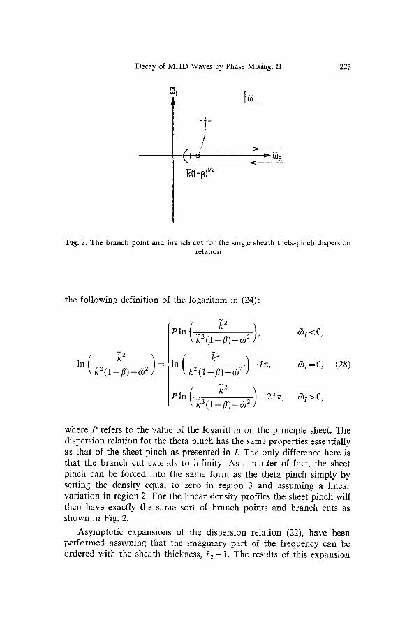
Fig. 2 shows the branch cut which is necessary in order to correctly define the logarithm in the complex & plane. The analytic continuation of the dispersion relation across the branch cut is carried out by using
Decay of MHD Waves by Phase Mixing. II
i
/ i
"E'it-p)v2
223
Fig. 2. The branch point and branch cut for the single sheath theta-pinch dispersion relation
the following definition of the logarithm in (24):
~ 2
~2 ), (5z < 0, PIn ( ~.2 (1 f-fi)_ c52
in ( ~c2 ( l _ f l ) _ c52 ) - ire, cSr=O, (28)
1>0,
where P refers to the value of the logarithm on the principle sheet. The dispersion relation for the theta pinch has the same properties essentially as that of the sheet pinch as presented in L The only difference here is that the branch cut extends to infinity. As a matter of fact, the sheet pinch can be forced into the same form as the theta pinch simply by setting the density equal to zero in region 3 and assuming a linear variation in region 2. For the linear density profiles the sheet pinch will then have exactly the same sort of branch points and branch cuts as shown in Fig. 2.
Asymptotic expansions of the dispersion relation (22), have been performed assmning that the imaginary part of the frequency can be ordered with the sheath thickness, f2 -1 . The results of this expansion
224 W. Grossmann and J. Tataronis:
for cSR and (51 are:
~ ~ 1 [I~.(~:) m2+k 2 ~aF2(~2_1)ln(o52 - ~2 e)~=Ogo-~-~ol, im(~ ) (5o2+~2fl ~2(l_f l i ) J, (29)
7~ c5,=~_~o (5_1)~ca I ; (k) mZ+Ic 2 +V:z fl Fz' (30)
where c5 o is the root of the dispersion relation for the sharp boundary case. Numerical calculations have shown that the asymptotic formulas approximate the actual numerically computed roots of (22) very closely over the interval 0 </~ < 1.
The root which we calculate from (22) is shown schematically in Fig. 2 by the dashed cross. As the sheath thickness uniformly goes to zero, this root moves along the indicated dotted path and converges uniformly to the root on the real ~o axis given by the sharp boundary dispersion relation.
Again, as indicated in the companion paper, there are an infinity of roots of the dispersion relation, Eq. (22); however, these extraneous roots must be discarded and are considered to be non-observable. As mentioned in / , this point is made by Zedlacek. Further, as indicated in the Fig. 2, the sharper the profile in the sense that the sheath thickness decreases, the less damped will be the wave. In the following, however, it will be observed that even with as small a sheath as f 2 - 1 ~0.01, significant damping is found. We present now the results of numerical solutions of the dispersion relation (22), for the real and imaginary parts of the eigenvalue as a function of sheath thickness,/~ and ft.
IH. Numerical Results
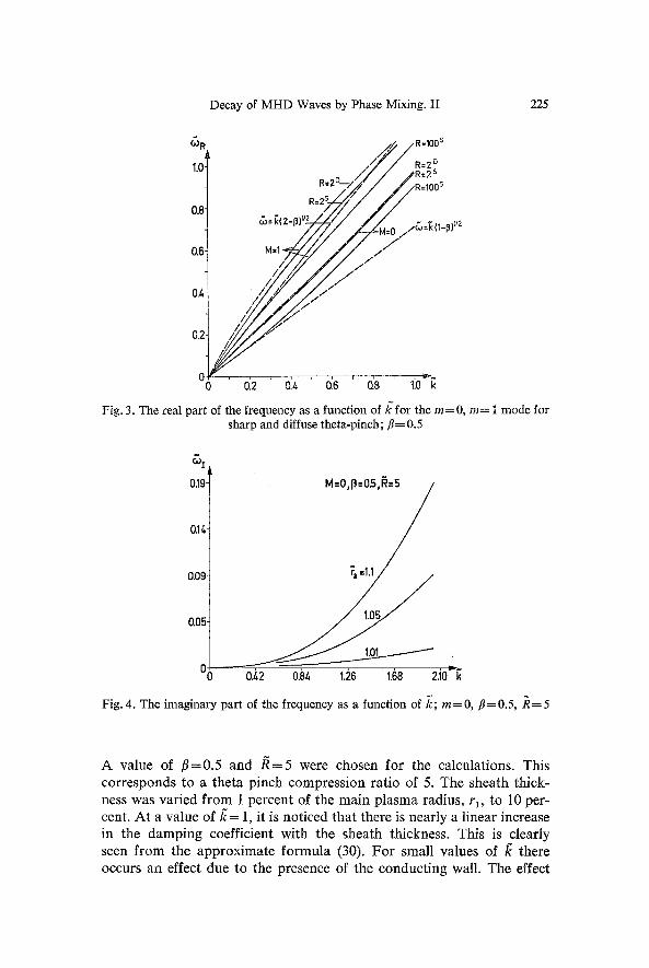
We present in Fig. 3 the real part of the frequency, (5 R, calculated from both the sharp and diffuse profile dispersion relation. Shown are results for both m = 0 and m = 1 modes. The indices ( )~ are respectively: e=s , d (sharp, diffuse profile), 7=/1 (wall radius divided by rl). The diffuse profile result was obtained for the sheath, thickness, ~2-1, taken to be 0.1. Similar to the sheet pinch result, the real frequency r5 R computed from the diffuse profile relation is close to the sharp boundary result and in all cases yields a value slightly larger than that for the sharp boundary case. As already mentioned, the approximate formula (29), yields very closely the numerically computed results using the full dis- persion relation.
Fig. 4 shows results from the numerical computations for the imagi- nary part of the frequency, c5~ of the m =0 mode as a function of /~.
Decay of MHD Waves by Phase Mixing. II 225
t~ R
1'0 I 0.8
0'6 t
0.Z' t
0.2-
0 0 Fig. 3. The real part
v R=100 s
R=2 D / ~ R=2s
R=100 s / / i / ~ / / / . , I R = 2 / / ~
, ,Z, / ' / / / "
y- 0:2 0)~ 0.6 0.8 1.0 k
of the frequency as a function of/~for t h e / = 0 , m= 1 mode for sharp and diffuse theta-pinch; fl= 0.5
019
0.II+
0.09
0.05
M=o,p=o.s,~~
T / O.Z2 0.84 1.26 1.68 2.10 k
Fig. 4. The imaginary part of the frequency as a function of 7c; m=0, fl=0.5, /}=5
A value of f l=0 .5 and / ~ = 5 were chosen for the calculations. This corresponds to a theta pinch compression ratio of 5. The sheath thick- ness was varied f rom 1 percent of the main plasma radius, r~, to 10 per- cent. At a value of/~ = 1, it is noticed that there is nearly a linear increase in the damping coefficient with the sheath thickness. This is clearly seen f rom the approximate formula (30). For small values of /~ there occurs an effect due to the presence of the conduct ing wall. The effect
226 W. Grossmann and J. Tataronis:
o.391
0,29-
0,19-
0,10-
0 i lm~ 0 2.10 k
y j 0),2 0.8t, 1.26 1.68
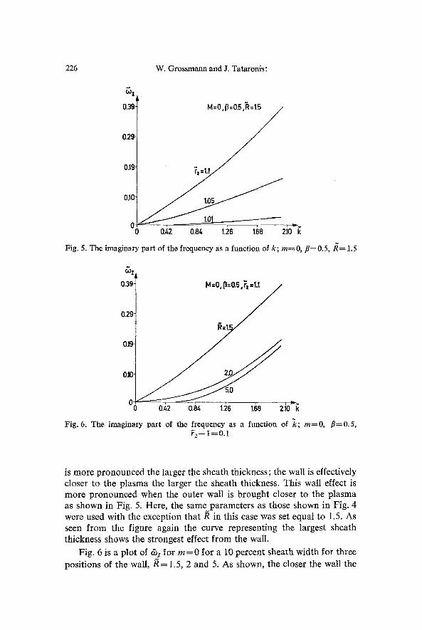
Fig. 5. The imaginary part of the frequency as a function of k; m=0, fl=0.5,/~= 1.5
r~ Z
0.39:
0.29"
0,19"
0.10
0 0
M=O, ll=0"5 U
0.i2 0.S& 1,26 1.68 2.10 k Fig. 6. The imaginary part of the frequency as a function of 7c; m=O, fl=0.5,
~2-1=0.1
is more pronounced the larger the sheath thickness; the wall is effectively closer to the plasma the larger the sheath thickness. This wall effect is more pronounced when the outer wall is brought closer to the plasma as shown in Fig. 5. Here, the same parameters as those shown in Fig. 4 were used with the exception that /~ in this case was set equal to 1.5. As seen f rom the figure again the curve representing the largest sheath thickness shows the strongest effect f rom the wail.
Fig. 6 is a plot of &i for m = 0 for a 10 percent sheath width for three positions of the wall,/~ = 1.5, 2 and 5. As shown, the closer the wall the
Decay of MHD Waves by Phase Mixing. II 227
r3 z
0.26-
0.19-
0.13-
0.06-
0 0
M=1,13=O.5,gt=5
=1.1
1.01 0.~2 o.84 i.i6 1.6B 2.10 k
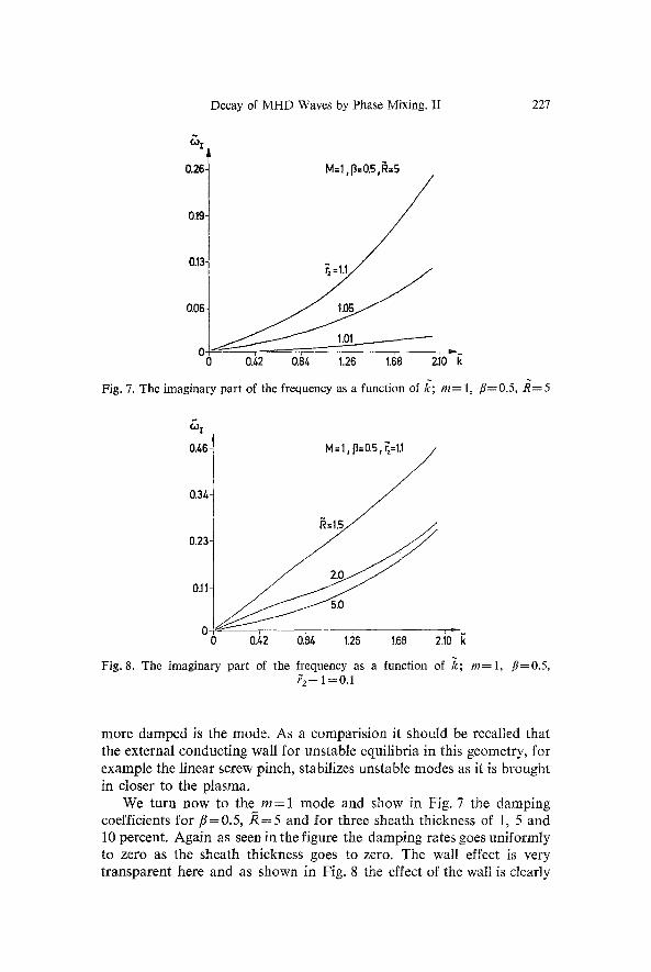
Fig. 7. The imaginary part of the frequency as a function of 1~; m= 1, /Y=0.5, R = 5
r
0.463 M=I, p ~
~ ~ = t s / /
0.23-
2.0 0.11-
0- 0 0./+2 0.84 1.26 1.68 2.10 k Fig. 8. The imaginary part of the frequency as a function of k; re=l , fl=0.5,
~2-1=0.1
more damped is the mode. As a comparis ion it should be recalled that the external conduct ing wall for unstable equilibria in this geometry, for example the linear screw pinch, stabilizes unstable modes as it is brought in closer to the plasma.
We turn now to the m = 1 mode and show in Fig. 7 the damping coefficients for fl = 0.5, /~ = 5 and for three sheath thickness of 1, 5 and 10 percent. Again as seen in the figure the damping rates goes uniformly to zero as the sheath thickness goes to zero. The wall effect is very t ransparent here and as shown in Fig. 8 the effect of the wall is clearly
228 W. Grossmann and J. Tataronis:
.243 ~ = . 6
.155" T=I T=I T = ~R J
iT=2 M ,: 1 .073- . o.1 o12 o'.4 d.s
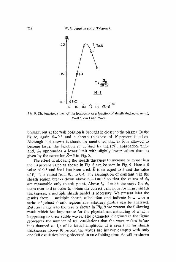
I ig. 9. The imaginary part of the frequency as a function of sheath thickness; m= 1, //=0.5, ~:=1 and R----5
brought out as the wall position is brought in closer to the plasma. In the figure, again fl=0.5 and a sheath thickness of 10 percent is taken. Although not shown it should be mentioned that as /~ is allowed to become large, the function F, defined by Eq. (59), approaches unity and, c51 approaches a lower limit with slightly lower values than as given by the curve for /~ = 5 in Fig. 8.
The effect of allowing the sheath thickness to increase to more than the 10 percent value as shown in Fig. 8 can be seen in Fig. 9. Here a fl value of 0.5 and/~= 1 has been used./~ is set equal to 5 and the value of f z - 1 is varied from 0.1 to 0.4. The assumption of constant ~ in the sheath region breaks down above 7 2 - 1 ~ 0 . 3 so that the values of r5I are reasonable only to this point. Above f 2 - 1 = 0 . 3 the curve for c5i turns over and in order to obtain the correct behaviour for larger sheath thicknesses, a multiple sheath model is necessary. We present later the results from a multiple sheath calculation and indicate how with a series of joined sheath regions any arbitrary profile can be analysed. Returning again to the results shown in Fig. 9 we present the following result which has importance for the physical understanding of what is happening to these stable waves. The parameter T defined in the figure represents the number of full oscillations that the wave makes before it is damped to 1/e of its initial amplitude. It is seen that for sheath thicknesses above 10 percent the waves are heavily damped with only one full oscillation being observed in an e-folding time. As will be shown
Decay of MHD Waves by Phase Mixing. II 229
.t,-
.3-
.2-
.1-
bl=l
.2 j
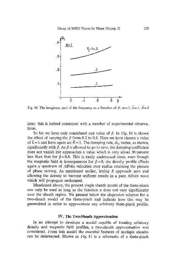
Fig. 10. The imaginary part of the frequency as a function of fl; rn= 1, if= 1, R~=5
later, this is indeed consistent with a number of experimental observa- tions.
So far we have only considered one value of ft. In Fig. 10 is shown the effect of varying the fl from 0.2 to 0.8. Here we have chosen a value of/~ = 1 and have again set/~ = 5. The damping rate, c5i, varies, as shown, significantly with ft. As/3 is allowed to go to zero, the damping coefficient does not vanish but approaches a value which is only about 30 percent less than that for /3=0.8 . This is easily understood since, even though the magnetic field is homogeneous for/3 = 0, the density profile effects again a spectrum of Alfv6n velocities over radius retaining the picture of phase mixing. As mentioned earlier, letting /3 approach zero and allowing the density to become uniform results in a pure Alfvdn wave which will propagate undamped.
Mentioned above, the present single sheath model of the theta-pinch can only be used as long as the function c~ does not vary significantly over the sheath region. We present below the dispersion relation for a two-sheath model of the theta-pinch and indicate how this may be generalized in order to approximate any arbitrary theta-pinch profile.
IV. The Two-Sheath Approximation
In an attempt to develope a model capable of treating arbitrary density and magnetic field profiles, a two-sheath approximation was considered. From this modeI the essential features of multiple sheaths can be determined. Shown in Fig. 11 is a schematic of a theta-pinch
230 W. Grossmann and J. Tataronis:
f , /
r=O
/~1 A2
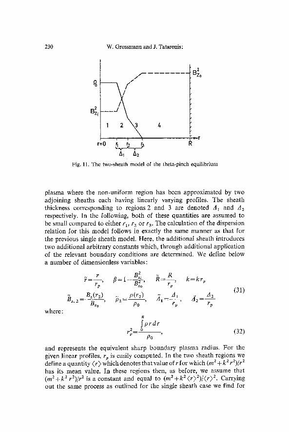
Fig. 1 l. The two-sheath model
2 Bzo
4
of the theta-pinch equilibrium
plasma where the non-uniform region has been approximated by two adjoining sheaths each having linearly varying profiles. The sheath thickness corresponding to regions2 and 3 are denoted A~ and A2 respectively. In the following, both of these quantities are assumed to be small compared to either ra, r2 or r3. The calculation of the dispersion relation for this model follows in exactly the same manner as that for the previous single sheath model. Here, the additional sheath introduces two additional arbitrary constants which, through additional application of the relevant boundary conditions are determined. We define below a number of dimensionless variables:
? = - - , f l= 1 - - - ~ - , k = k r v rp Bzo rp
B=(r2) p(r2) z~l= A1 z ]2- A2 13~,2- B= ~ , P2-- Po " rp ' rp
where:
(31)
R
S p r d r 2 0
Po (32)
and represents the equivalent sharp boundary plasma radius. For the given linear profiles, rp is easily computed. In the two sheath regions we define a quantity ( r ) which denotes that value of r for which (m 2 + k 2 r2)/r 2 has its mean value. In these regions then, as before, we assume that (rn 2 + k 2 r2)/r 2 is a constant and equal to (m 2 + k 2 (r )Z) / (r ) 2. Carrying out the same process as outlined for the single sheath case we find for
Decay of MHD Waves by Phase Mixing. II 231
the two sheath model the following dispersion relation:
where
-2 /~n (k }11 ) ] rl F(1 + c5 t + 62)- ~ (33) ~Z=lcZ l-fl ~ 1,,,(k?~)
F= Irn(Ig'~3) K~m(k R ) - Km(k~'3) ffm(tg R ) I,.(kr3) K~(k R)-K=(kr3)Im(k R)
(34)
leA, F(m 2 + ~c 2 @'2) 2)
- - \ Z , 2
~2 ~ ~2 ~2 ln(CO P2-k*B:.2]
\ c~ ~-~(1-~) 1' (35)
~2F(m 2 + ~2 (~:3)z) 152 = -- ~2 [(~2~ 2 .@/~2(1 __~2, 2)]
(~: P ) ~-~ 7 - 2
In 2 c52~ (36)
Various limits of the above disper~on relation can be taken. For ex- ample, letting P2 approach zero as A 2 approaches zero yields the single sheath result since there the approximation was made that f3~? , . Setting both z~, and z] 2 equal to zero recovers the sharp boundary result. In the above, instead of one, two logarithms appear and some care must be taken in interpreting correctly the branch points and the corresponding proper branch cuts.
The function 61 has branch points at the frequencies
and (37)
~=+~ sz,2 - (~2)1/2 �9
The function fi2 has branch points at the frequencies
~ = + ~ : kz,2 (38) - (,~2)1/2
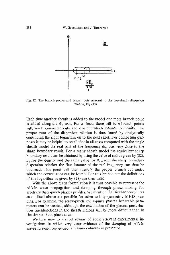
which co-incide with the second set of branch points of 6,. Shown in Fig. 12 are the corresponding branch cuts which connect the branch points. When the density P2 is allowed to approach zero the branch point given by (38) moves off along the c5 R axis to infinity yielding again the branch cut shown in Fig. 2. This is the proper single sheath limit.
232 W. Grossmann and J. Tataronis:
\ i "~.IY
kBz 2 p2112
~ R
Fig. 12. The branch points and branch cuts relevant to the two-sheath dispersion relation, Eq. (33)
Each time another sheath is added to the model one more branch point is added along the c5 R axis. For n sheets there will be n branch points with n - 1 , connected cuts and one cut which extends to infinity. The proper root of the dispersion relation is thus found by analytically continuing the right logarithm on to the next sheet. For computing pur- poses it may be helpful to recall that in all cases computed with the single sheath model the real part of the frequency (5 R was very close to the sharp boundary result. For a many sheath model the equivalent sharp boundary result can be obtained by using the value of radius given by (32), Po for the density and the same value for ft. From the sharp boundary dispersion relation the first interate of the real frequency can thus be obtained. This point will then identify the proper branch cut under which the correct root can be found. For this branch cut the definitions of the logarithm as given by (28) are then valid.
With the above given formulation it is thus possible to represent the Alfv~n wave propagation and damping through phase mixing for arbitrary theta-pinch plasma profiles. We mention that similar procedures as outlined above are possible for other axially-symmetric MHD plas- mas. For example, the screw-pinch and z-pinch plasma for stable para- meters can be treated, although the calculation of the plasma perturba- tion eigenfunctions in the sheath regions will be more difficult than in the simple theta-pinch case.
We turn now to a short review of some relevant experimental in- vestigations in which very clear evidence of the damping of Alfv~n waves in non-homogeneous plasma columns is presented.
Decay of MHD Waves by Phase Mixing. II 233
V. Review of Experimental Investigations
As mentioned earlier, there are a good number of experimental investigations reported in the literature which indicate that damping of stable Alfv6n waves has been observed. We review here several of the more recent investigations and attempt to compare the experimental observations with the present theory as well as classical theory of MHD wave damping as given, for example, by Braginsky [5].
Wooton, Nalesso and Newton, [6] have reported on experiments aimed at launching m = 1 Alfv6n waves along a long cylindrical theta- pinch column. The experimental setup is described further by Junker et al. [7] and is an integral part of a series of experiments whose aim is to investigate the feasibility of feedback stabilizing high beta plasmas. As mentioned earlier in this report there is a question in all feedback systems as to whether or not the stabilizing signals (forces) will produce waves travelling with Alfv6n velocity and which could interfere or cause erroneous signals at other observation positions. From the experimental results presented in Ref. [6] it appears as if this question of wave interference has been answered in the negative. A 350 cm long theta- pinch coil was used and several types of theta-pinch plasma profiles were produced. In order to produce the m = l perturbations on the plasma column a saddle or sector coil was placed outside the glas vacuum vessel at the mid point of the pinching coil. The sector coil was connected to a signal generator which was capable of either oscillatory or steady state operation. Most of the experiments performed were with the oscillatory mode of operation. At a driving frequency of 1.35 x 10⁶ radians per second the sector coil displaced the plasma column 6 milli- meters at maximum amplitude. A series of optical observation ports were placed at intervals along the longitudinal axis. Correlation of the signals obtained from the various axial positions yielded information concerning the amplitude and velocity of the propagating Alfv6n waves. The first set of experiments were performed with a very low beta configuration; betas0.06 on the axis of the column. The density profile was approxi- mately gaussian in shape and very broad. Measured temperatures were of the order of several electron volts. Using the sector coil in the driven mode, rn= 1 Alfv6n waves were observed to damp completely away in a distance equivalent to the spacing between the plasma column and the perturbing coils. At such low temperatures resistive damping of Alfv6n waves can be significant [5] and the damping decrement can be of the same order as that which occurs due to phase mixing. From these results then we cannot conclude that damping due to phase mixing was observed.
The second set of experiments, however, were performed with a high beta configuration; beta,,~0.6 on the plasma axis. Again the density
234 W. Grossmann and J. Tataronis:
profile was gaussian with a compression ratio of the order of 5 -6 . Measured electron temperatures of the order of 30- 60 eV were obtained. Classical damping through resistive and viscous effects [5] is not sufficient to explain the observed strong damping of the m = 1 Alfv6n wave. The Alfv6n wave was observed to propagate away from the source with a speed consistent with Eq. (29) solved for ~//~. Without accurate knowl- edge of the value of the wavenumber/~ it is not possible to compare the experimental results with the predictions of the present theory. How- ever, approximate estimates of the Alfv6n wave frequency and velocity taken from the data given in Ref. [6] allows an approximation for ~. Further, with a guess that the density profile can be approximated by a flat portion and a sheath varying from 10 to 30 ~ yields damping decre- ments which are consistent with the experimental findings. It is then entirely possible that Alfv6n wave damping due to phase mixing has been observed in the experiments of Wooton et al. [6].
For a more detailed proof of experimental verification of the damping by phase mixing of Alfv6n waves we consider the following experiments performed with the Garching ISAR I facility as reported by Neuhauser et al. [8]. Here, a 5A m long theta-pinch coil with I= 1 helical grooves produced a highly compressed, betag0.5-0.7, plasma column which executed m = 1 Alfv6n oscillations about its equilibrium position. The period length of the m = 1 wave was the same as the helical period thus specifying/~ accurately. A series of experiments with ion temperatures varying from 50 to 300 eV were performed and in all cases the m = 1 Alfv6n oscillations were observed to damp away with &I/~R ~ 0.2--0.1. Again it can be shown that both resistive and viscous damping for these plasma conditions contributes only negligibly to Alfv6n wave damping. Using the experimentally measured profiles and approximating them with the sheath model of the present paper yields values of &I/&R which agree very well with the experimental findings. The agreement at the higher temperatures becomes worse and this is due no doubt to the breakdown in the validity of the hydromagnetic model [5] used for the present theory. From the above mentioned experimental findings we conclude that the damping Alfv6n waves through phase mixing has been verified.
We turn now to a completely different type of plasma configuration in which damped Alfv6n waves have been observed. Nielsen [9] has described a magnetically confined arc plasma using helium and an attempt to heat this plasma further using RF fields. Recently [10] it has been observed that the RF heating generator, attached to a co-axial cathode assembly, acts as an Alfv6n wave generator in a manner similar to the method proposed by Furth [11]. The Alfv6n frequency and wave- length could be measured along with the damping decrement. Strong
Decay of MHD Waves by Phase Mixing. II 235
damping was observed. Although the dispersion relation of the present paper cannot be used to predict the observed Alfvrn wave damping of Nielsen (the arc plasma is more of a z-pinch configuration with a weak guide or axial field) it is felt that phase mixing plays a strong rule in explaining the results. An estimate of the classical damping is not possible without knowledge of the plasma profiles, however, the viscous effects should be relatively negligible for the arc plasma as described by Nielsen. The resistive damping could be of the same order as that due to phase mixing. At higher temperatures the phase mixing mechanism will tend to dominate.
We conclude the discussion of the experiments in which damped Alfvrn waves in non-homogeneous plasma columns have been observed. We should mention that the fast damping of Alfvrn waves by phase mixing could lead to a significant heating mechanism in both low as well as high beta plasmas. There is sufficient evidence, although no experimental measurements have as yet been taken, to believe that the energy in the Alfv6n wave through interaction with short wavelength magneto-acoustic waves becomes very quickly thermalized. The energy should go directly into the ions. If this is later borne out by experimental evidence then the Alfvrn wave damping could lead to a means of off- setting the energy loss in pinch plasmas after the fast compression stage. In low beta systems, Alfvrn wave damping due to phase mixing could well take over the role of effective "transit time magnetic pumping" at higher density and beta values than ordinarily assumed for classical TTMP heating.
Finally it should be mentioned that there is experimental evidence [1, 2] which indicates that no parametric excitation of other M H D in- stabilities has been observed during dynamic stabilization experiments on high beta columns.
VI. Conclusions
We have shown theoretically and verified through experimental evidence that torsional Alfvrn waves in non-uniform plasma columns are damped due to phase mixing. This damping could lead to an effective heating of ions in both high and low beta systems.
The authors would like to thank the following colleagues for constructive dis- cussions during the course of the investigations; Profs. H. Grad, H. Weitzner, D. Pfirsch, Drs. M. Kaufmann, J. Neuhauser.
References
1. Becker, G., Gruber, O., Herold, H.: Plasma Physics and Contr. Nucl. Fus. Res., Vol. I, 277 (1971).
2. Gruber, O.: Z. Physik 251, 333 (1972).
16 Z. Physik, Bd. 261
236 W. Grossmann and J. Tataronis: Decay of MHD Waves by Phase Mixing. II
3. Gribble, R.F. , Burnett, S. C., Harder, C.R.: Paper G1, Proc. of the Second Topical Conference on Pulsed High-Beta Plasmas, IPP-Report 1/127 (1972).
4. ZedlR~ek, Z.: J. Plasma Phys. 5, 239 (1971). 5. Braginsky, S. I.: Reviews of plasma physics, vol. I, edited by M. A. Leontovich.
New York: Consultants Bureau 1965. 6. Wooton, A., Nalesso, G.F . , Newton, A .A. : Paper C4, Proc. of the Second
Topical Conference on Pulsed High Beta Plasmas, IPP-Report 1/127 (1972). 7. Junker, J., Newton, A.A. , Bodin, H.: EPS IV. Europ. Conf. on Controlled
Fusions and Plasma Physics, Rome, August 31. Sept. 4 (1970). 8. Ffinfer, E., Kanfmann, M., Lotz, W., Neuhauser, J., Schramm, G., Seidel, U.:
IPP-Report 1/130, Feb. 1973. 9. Nielsen, C. E.: Bull. Am. Phys. Soc. 16, 1227 (1971).
10. Nielsen, C. E.: Personal Communication (1972). 11. Furth, H. P.: Univ. of Calif. Rad. Lab. Engineering Note UCRL-5423-T (1959).
W. Grossmann Max-Planck-Institnt f/ir Plasmaphysik D-8046 Garching bei Mfinchen Federal Republic of Germany
J. Tataronis Courant Institute of Mathematical Sciences New York University New York, N.Y. USA