d&c r64 soil nailing - home - roads and maritime · pdf filetest nail: a soil nail...
TRANSCRIPT
ROADS AND MARITIME SERVICES (RMS)
RMS SPECIFICATION D&C R64
SOIL NAILING
NOTICE
This document is a Roads and Maritime Services D&C Specification. It has been developed for use with Design & Construct roadworks and bridgeworks contracts let by Roads and Maritime Services. It is not suitable for any other purpose and must not be used for any other purpose or in any other context.
Copyright in this document belongs to Roads and Maritime Services.
REVISION REGISTER
Ed/Rev Number
Clause Number Description of Revision Authorised
By Date
Ed 1/Rev 0 First issue GM, IC W Stalder
30.06.11
Ed 1/Rev 1 Updated to accord with base (non-D&C) Specification R64 Ed 1/Rev 3.
GM, IC 29.11.12
Ed 1/Rev 2 Updated to accord with base (non-D&C) Specification R64 Ed 1/Rev 4.
Contracts Quality Manager
28.06.16
Edition 1 / Revision 2 ROADS AND MARITIME SERVICES June 2016
GUIDE NOTES (Not Part of the Deed)
G.1 Protective Treatment of Couplers, Nuts, Washers and Bearing Plates
Refer Clauses 2.2.2, 2.2.3 and 2.2.8.
Thermal diffusion coating (TDC) galvanizing may be used as an alternative to hot-dip galvanizing for couplers, nuts, washers and bearing plates.
Thermal diffusion galvanizing has the following advantages over hot-dip galvanizing:
(i) it produces zinc alloy layers of similar thickness to hot-dip galvanizing, without being susceptible to hydrogen embrittlement; and
(ii) it produces more consistent coating thickness compared with hot-dip galvanizing, resulting in more reliable bolt preloads when tensioned using torque wrenches.
The thickness of the thermal diffusion galvanizing must not be less than the hot-dip galvanizing. Tapping of nuts following thermal diffusion galvanizing is not usually done because of the hardness of the coating.
Thermal diffusion galvanizing must meet the requirements of ASTM A1059M-08 “Standard Specification for Zinc Alloy Thermo-Diffusion Coatings (TDC) on Steel Fasteners, Hardware, and Other Products”.
Hot-dip galvanizing must still be used for galvanizing of soil nail steel bars.
G.2 Soil Nail Thread
Refer Clauses 2.2.1 and 2.2.2.
Alternative to deformed bars and different thread profiles may be permitted provided that the threaded nut assembly of the soil nail exceeds the minimum breaking load of the bar.
Soil nail bar couplers using such threaded profiles may be permitted provided that the same requirements stated above are met.
ii
SPECIFICATION D&C R64
SOIL NAILING Copyright – Roads and Maritime Services
IC-DC-R64
VERSION FOR: DATE:
Edition 1 / Revision 2 ROADS AND MARITIME SERVICES June 2016

Soil Nailing D&C R64
CONTENTS
CLAUSE PAGE
FOREWORD ............................................................................................................................................... II RMS Copyright and Use of this Document ................................................................................... ii Base Specification ......................................................................................................................... ii
1 GENERAL ........................................................................................................................................ 1 1.1 Scope .............................................................................................................................. 1 1.2 Structure of the Specification ......................................................................................... 1 1.3 Definitions ...................................................................................................................... 1 1.4 Figures ............................................................................................................................ 3 1.5 Project Quality Plan ....................................................................................................... 4
2 MATERIALS .................................................................................................................................... 4 2.1 General ........................................................................................................................... 4 2.2 Soil Nails ........................................................................................................................ 4 2.3 Concrete Facing .............................................................................................................. 8
3 CONSTRUCTION ............................................................................................................................ 10 3.1 General ......................................................................................................................... 10 3.2 Storage and Handling ................................................................................................... 10 3.3 Construction Sequence ................................................................................................. 11 3.4 Soil Nail Installation ..................................................................................................... 12
4 INSTRUMENTED SOIL NAIL .......................................................................................................... 16
5 TESTING OF SOIL NAILS ............................................................................................................... 16 5.1 General ......................................................................................................................... 16 5.2 Soil Nail Tests .............................................................................................................. 17 5.3 Testing and Measuring Equipment............................................................................... 20 5.4 Records of Tests ........................................................................................................... 20
6 PLACEMENT OF CONCRETE FACING ............................................................................................. 21 6.1 General ......................................................................................................................... 21 6.2 Slope Surface Preparation ............................................................................................ 21 6.3 Drilling and grouting of Steel Mesh Support Anchor Bars .......................................... 21 6.4 Application of Shotcrete............................................................................................... 22
7 RECORDS FOR INSTALLATION ...................................................................................................... 23
ANNEXURES R64/A TO R64/B – (NOT USED) ........................................................................................ 24
ANNEXURE R64/C – SCHEDULES OF HOLD POINTS, WITNESS POINTS AND IDENTIFIED RECORDS ....... 24 C1 Schedule of Hold Points and Witness Points ............................................................... 24 C2 Schedule of Identified Records .................................................................................... 24
ANNEXURE R64/D – PLANNING DOCUMENTS ........................................................................................ 25
ANNEXURE R64/E – INSTRUMENTED SOIL NAILS .................................................................................. 26
ANNEXURES R64/F TO R64/L – (NOT USED) ......................................................................................... 29
Ed 1 / Rev 2 i
D&C R64 Soil Nailing
ANNEXURE R64/M – REFERENCED DOCUMENTS................................................................................... 29
LAST PAGE OF THIS DOCUMENT IS .......................................................................................................... 30
FOREWORD
RMS COPYRIGHT AND USE OF THIS DOCUMENT
Copyright in this document belongs to Roads and Maritime Services.
When this document forms part of a deed
This document should be read with all the documents forming the Project Deed.
When this document does not form part of a deed
This copy is not a controlled document. Observe the Notice that appears on the first page of the copy controlled by RMS. A full copy of the latest version of the document is available on the RMS Internet website: http://www.rms.nsw.gov.au/business-industry/partners-suppliers/specifications/index.html
BASE SPECIFICATION
This document is based on Specification RMS R64 Edition 1 Revision 4.
ii Ed 1 / Rev 2
(RMS COPYRIGHT AND USE OF THIS DOCUMENT - Refer to the Foreword after the Table of Contents)
RMS SPECIFICATION D&C R64
SOIL NAILING
1 GENERAL
1.1 SCOPE
This Specification sets out the requirements for soil nailing for the strengthening of earth slopes using grouted steel dowels (soil nails) installed at shallow inclination into the retained soil mass at nominated positions and levels shown on the Design Documentation drawings.
It covers the requirements for supply and installation of soil nails including compliance testing, and the associated concrete facing work on the slope surface.
A reinforced, formed concrete or shotcrete facing, acting as ‘diaphragm support’ for the retained structure, forms part of the Project Works.
1.2 STRUCTURE OF THE SPECIFICATION
This Specification includes a series of annexures that detail additional requirements.
1.2.1 (Not Used)
1.2.2 (Not Used)
1.2.3 Schedules of HOLD POINTS, WITNESS POINTS and Identified Records
The schedules in Annexure R64/C list the HOLD POINTS and WITNESS POINTS that must be observed. Refer to Specification RMS D&C Q6 for the definitions of HOLD POINTS and WITNESS POINTS.
The records listed in Annexure R64/C are Identified Records for the purposes of RMS D&C Q6 Annexure Q/E.
1.2.4 Planning Documents
The PROJECT QUALITY PLAN must include each of the documents and requirements shown in Annexure R64/D and must be implemented.
1.2.5 Referenced Documents
Standards, specifications and test methods are referred to in abbreviated form (e.g. AS 2350). For convenience, the full titles are given in Annexure R64/M.
1.3 DEFINITIONS
The terms “you” and “your” mean “the Contractor” and “the Contractor’s” respectively.
Ed 1 / Rev 2 1
(RMS COPYRIGHT AND USE OF THIS DOCUMENT - Refer to the Foreword after the Table of Contents)
D&C R64 Soil Nailing
The following definitions apply to this Specification:
Annulus: Radial space between the soil nail and the drillhole wall.
Batch of Grout: Any quantity of grout used for grouting in one continuous operation in one day.
Curing: The control of temperature and moisture in the concrete until the concrete has developed required properties.
Grout: A mixture, similar to mortar, but more workable and possibly without any sand or fine aggregate, proportioned to produce a pourable liquid which does not readily segregate into its constituents during pouring or pumping.
Instrumented Nail: A specially made soil nail in which strain gauges are installed to monitor the stress/strain behaviour of the nail steel bar.
Mortar: A mixture of cement, water and sand (fine aggregate), with or without chemical admixtures with a characteristic compressive strength at 28 days of not less than 25 MPa.
Nail Head: The upper part of the nail composed of a bearing plate, nut and washer, and the portion of steel reinforcement protruding above the bearing plate. For permanent nails in certain projects, the nail head may consist of a bent reinforcement bar to be covered by concrete facing.
Permanent Nail: A soil nail installed on the Construction Site as the permanent work of the Project Works and will be selectively tested under 1.5 time design load via the Acceptance Test procedure.
Rebound: Shotcrete material that bounces off the receiving surface.
Sealed Curing: Curing at ambient temperature in which the concrete surface is sealed by at least two coats of a curing compound conforming to this Specification.
Shotcrete: A structural sprayed concrete containing fine and coarse aggregates, water and cement, with or without the addition of set accelerators. Compaction of the material is achieved by the force of the jet impacting on the surface. The shotcrete is reinforced by galvanised steel mesh.
Soil Nail: A steel reinforcement bar inserted centrally into a pre-drilled hole and grouted in place.
Standard Moist Curing: Standard moist curing as defined in AS 1012, Part 8.
Test Nail: A soil nail specially installed on the Construction Site for testing its ultimate pull out capacity through the Suitability Test procedure. It does not form part of the permanent works for the deed.
Wet Curing: Curing at ambient temperature in which the concrete surface is effectively covered with water or placed in a fog room/chamber with a relative humidity exceeding 98%.
2 Ed 1 / Rev 2
(RMS COPYRIGHT AND USE OF THIS DOCUMENT - Refer to the Foreword after the Table of Contents)
Soil Nailing D&C R64
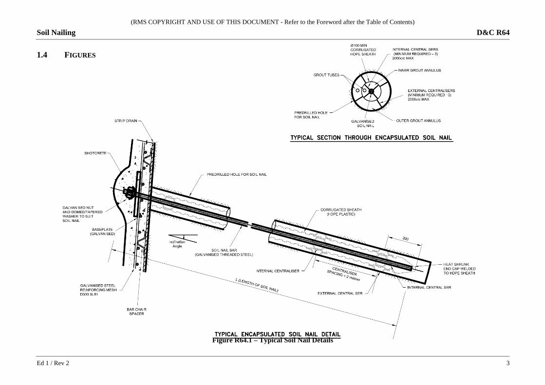
1.4 FIGURES
Figure R64.1 – Typical Soil Nail Details
Ed 1 / Rev 2 3
(RMS COPYRIGHT AND USE OF THIS DOCUMENT - Refer to the Foreword after the Table of Contents)
D&C R64 Soil Nailing
1.5 PROJECT QUALITY PLAN
The PROJECT QUALITY PLAN must include each of the documents and requirements listed in Annexure R64/D and must be implemented.
In all cases where this Specification refers to the manufacturer’s recommendations, these must be included in the PROJECT QUALITY PLAN.
2 MATERIALS
2.1 GENERAL
Materials used for manufacturing soil nails and concrete facing must be produced by manufacturers operating under a quality management system, which satisfies the requirements of ISO 9001.
All materials used for the construction of soil nails and concrete facing must be accompanied by a manufacturer’s certificate of conformity, verifying that the proposed materials comply with all the requirements of this Specification.
Submit the certificate of conformity to the Geotechnical Design Representative at least 10 working days before the commencement of soil nailing works. Submission of this certificate constitutes a HOLD POINT.
HOLD POINT
Process Held: Commencement of soil nailing works.
Submission Details: At least 10 working days prior to the commencement of soil nailing works, submit to the Nominated Authority certificate of conformity for the materials used in the soil nailing works.
Release of Hold Point: The Nominated Authority will consider the submitted documents prior to authorising the release of the Hold Point.
2.2 SOIL NAILS
2.2.1 Soil Nail Steel Bars
Steel reinforcement bars for soil nails must be Grade 500N deformed bar to AS 4671, or other carbon steel grades with a minimum characteristic yield strength of 500 MPa and which meet the requirements for ultimate strength and elongation for Grade 500N steel bars shown in Table 2 of AS 4671. Provide the relevant test certificates demonstrating conformity.
Each delivery of steel bars must be accompanied by documentation showing the mill certificate and Lot number.
The bars must be threaded at one end. The thread must be ISO coarse pitch thread to AS 1275, or other thread profiles where approved by RMS Representative.
4 Ed 1 / Rev 2
(RMS COPYRIGHT AND USE OF THIS DOCUMENT - Refer to the Foreword after the Table of Contents)
Soil Nailing D&C R64
The steel reinforcement bar must be hot-dip galvanized to AS/NZS 4680, except that the minimum average coating weight must be 600 g/m2 (equivalent to 85 microns thickness).
Inspect all steel reinforcement bars carefully to ensure that it is true to size and free from defects that may impair strength and durability.
2.2.2 Couplers
Steel reinforcement bars longer than 12 m must be joined using mechanical couplers. The use of couplers to extend the steel reinforcement bars must not result in a decrease in the tensile strength of the joined bar assembly.
All couplers must be hot-dip galvanized to AS/NZS 4680, or galvanized by an alternative process approved by RMS Representative.
The couplers must be of dimensions that do not interfere with the grouting and installation of soil nails.
2.2.3 Nuts
Nuts for soil nails must be grade C complying with AS 1112.3 and property Class 5 complying with AS 4291.2 or equivalent to suit the threaded end of the soil nail. The thread must conform to the ISO coarse pitch thread in accordance with AS 1275.
All nuts must be hot-dip galvanized in accordance with AS 1214, or galvanised by an alternative process approved by RMS Representative.
2.2.4 Encapsulation (Corrugated Plastic Sheath)
Encapsulate soil nails in a corrugated plastic sheath sealed at the buried end.
The corrugated plastic sheath must be manufactured from high density polyethylene complying with AS 4131, with a minimum uniform wall thickness of 2.0 mm.
The corrugated sheathing must meet the requirements of either of the following:
• ASTM D3350 for HDPE with cell classification 335533C, or
• ASTM D1784 for rigid PVC with classification 13464B.
The pitch of corrugations must be within six to twelve times the sheath wall thickness, and amplitude of corrugations must be not less than three times the wall thickness.
The finished internal and external surfaces of the corrugated plastic sheath must be clean and free from flaws, pin holes, bubbles, cracks and other defects.
Where possible, corrugated plastic sheath must be unjointed for the full length of soil nail.
Where joints cannot be avoided, provide sheath joints by lapping of at least 100 mm together with liberal use of solvent glues appropriate for the sheathing material or with heat-shrink sealing. The strength of the joint must be at least 90% of the parent material. Joints must be such that the continuity of the protective system over the whole length of the nail is unimpaired with respect to the physical and electro-chemical barrier.
Ed 1 / Rev 2 5
(RMS COPYRIGHT AND USE OF THIS DOCUMENT - Refer to the Foreword after the Table of Contents)
D&C R64 Soil Nailing
A screw-on cap or a heat-shrink boot must be placed on the end of the sheath in contact with the ground and bonded with an appropriate solvent glue or heat shrink sealing.
Provide a manufacturer’s certificate of conformity to the Geotechnical Design Representative which includes the following information about the corrugated plastic sheath to be used:
(a) manufacturer’s name and current address;
(b) full product name;
(c) style, merge, or product code number;
(d) outer and inner diameter;
(e) wall thickness;
(f) amplitude and pitch.
2.2.5 Centralisers
Manufacture centralisers from materials which have no deleterious effects to the reinforcing system and will not corrode. The centralisers must be of a shape that permits the free flow of grout but still performs the centralising function. They must not be compressible, bulky or cause decoupling of the grout or de-bonding of the grout/steel reinforcement interface.
Do not use plastic slip-on centralisers, or rely on the grout tube spirally wound around the soil nail to act as centraliser.
Centralisers must be firmly fixed to the nails and to the encapsulation and must be provided both inside and outside of nail assemblies.
Provide centralisers at intervals not exceeding 2 m along the corrugated plastic sheath or reinforcement bar, with the first and last centraliser 0.3 m from the end of each nail, to ensure that it is centred within the drillhole. Provide a minimum of three (3) centralisers for each nail for the annulus between the drillhole and the corrugated plastic sheath/reinforcement bar, or between the bar and the drillhole.
Subject to the results of the soil nail design, maintain a minimum grout cover of 25 mm between the corrugated plastic sheath and the drillhole; and 20 mm between the reinforcement bar and the encapsulation sheath at any location along the length of the bar or sheath. Where reinforcement bars are not encapsulated, the minimum cover between the bar and the drillhole must be 30 mm at any location, unless otherwise specified on the Design Documentation drawings.
2.2.6 Grout Tubes
Grout tubes must have a minimum internal diameter of 12 mm for the core and outer annulus grouting and must be made from high-density polyethylene with a wall thickness of at least 2.0 mm or its equivalent to AS 4131. Tubing must be of adequate strength to resist damage during both installation and grouting.
Grout tubes must extend to the lowest portion of the drilled hole to ensure thorough grout penetration and must be securely fixed to the steel reinforcement to prevent displacement or dislodging.
Provide separate grout tubes for grouting the inside and outside of the encapsulated soil nail and for likely second stage grouting.
6 Ed 1 / Rev 2
(RMS COPYRIGHT AND USE OF THIS DOCUMENT - Refer to the Foreword after the Table of Contents)
Soil Nailing D&C R64
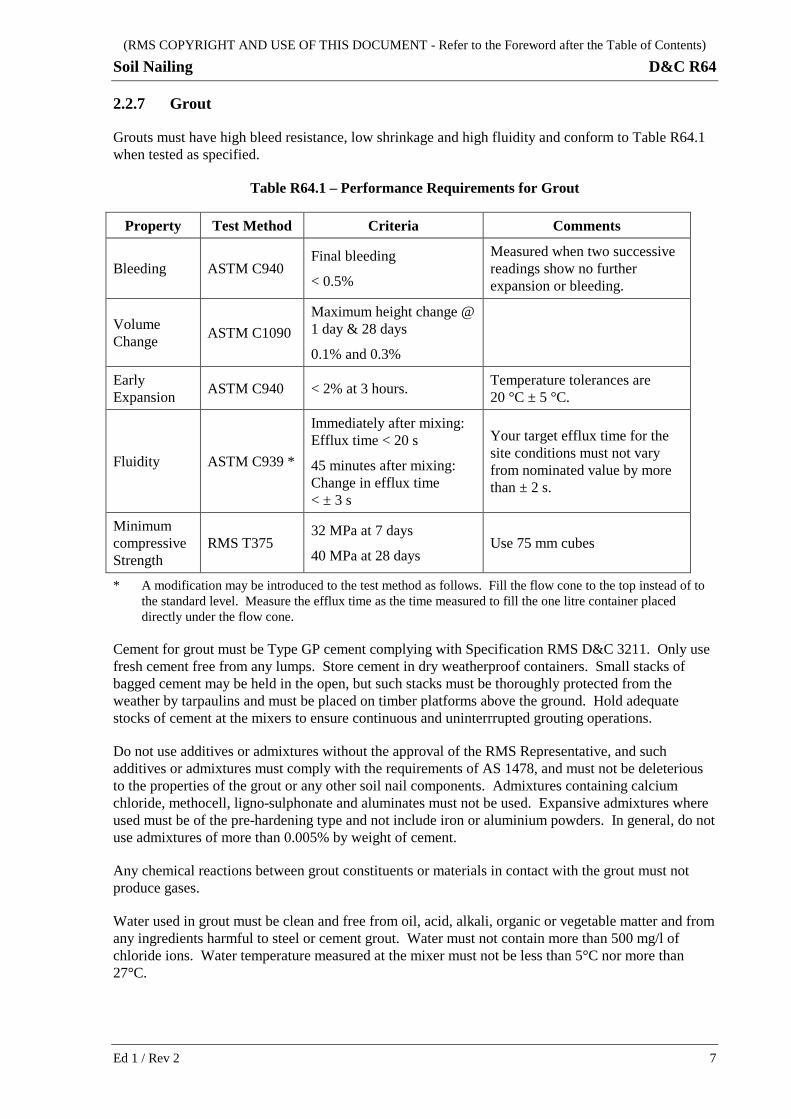
2.2.7 Grout
Grouts must have high bleed resistance, low shrinkage and high fluidity and conform to Table R64.1 when tested as specified.
Table R64.1 – Performance Requirements for Grout
Property Test Method Criteria Comments
Bleeding ASTM C940 Final bleeding
< 0.5%
Measured when two successive readings show no further expansion or bleeding.
Volume Change ASTM C1090
Maximum height change @ 1 day & 28 days
0.1% and 0.3%
Early Expansion ASTM C940 < 2% at 3 hours. Temperature tolerances are
20 °C ± 5 °C.
Fluidity ASTM C939 *
Immediately after mixing: Efflux time < 20 s
45 minutes after mixing: Change in efflux time < ± 3 s
Your target efflux time for the site conditions must not vary from nominated value by more than ± 2 s.
Minimum compressive Strength
RMS T375 32 MPa at 7 days
40 MPa at 28 days Use 75 mm cubes
* A modification may be introduced to the test method as follows. Fill the flow cone to the top instead of to the standard level. Measure the efflux time as the time measured to fill the one litre container placed directly under the flow cone.
Cement for grout must be Type GP cement complying with Specification RMS D&C 3211. Only use fresh cement free from any lumps. Store cement in dry weatherproof containers. Small stacks of bagged cement may be held in the open, but such stacks must be thoroughly protected from the weather by tarpaulins and must be placed on timber platforms above the ground. Hold adequate stocks of cement at the mixers to ensure continuous and uninterrrupted grouting operations.
Do not use additives or admixtures without the approval of the RMS Representative, and such additives or admixtures must comply with the requirements of AS 1478, and must not be deleterious to the properties of the grout or any other soil nail components. Admixtures containing calcium chloride, methocell, ligno-sulphonate and aluminates must not be used. Expansive admixtures where used must be of the pre-hardening type and not include iron or aluminium powders. In general, do not use admixtures of more than 0.005% by weight of cement.
Any chemical reactions between grout constituents or materials in contact with the grout must not produce gases.
Water used in grout must be clean and free from oil, acid, alkali, organic or vegetable matter and from any ingredients harmful to steel or cement grout. Water must not contain more than 500 mg/l of chloride ions. Water temperature measured at the mixer must not be less than 5°C nor more than 27°C.
Ed 1 / Rev 2 7
(RMS COPYRIGHT AND USE OF THIS DOCUMENT - Refer to the Foreword after the Table of Contents)
D&C R64 Soil Nailing
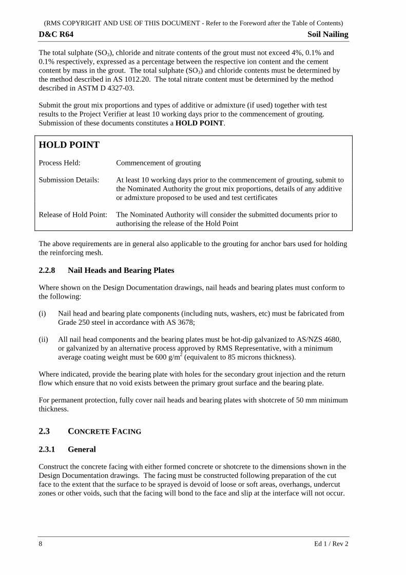
The total sulphate (SO3), chloride and nitrate contents of the grout must not exceed 4%, 0.1% and 0.1% respectively, expressed as a percentage between the respective ion content and the cement content by mass in the grout. The total sulphate (SO3) and chloride contents must be determined by the method described in AS 1012.20. The total nitrate content must be determined by the method described in ASTM D 4327-03.
Submit the grout mix proportions and types of additive or admixture (if used) together with test results to the Project Verifier at least 10 working days prior to the commencement of grouting. Submission of these documents constitutes a HOLD POINT.
HOLD POINT
Process Held: Commencement of grouting
Submission Details: At least 10 working days prior to the commencement of grouting, submit to the Nominated Authority the grout mix proportions, details of any additive or admixture proposed to be used and test certificates
Release of Hold Point: The Nominated Authority will consider the submitted documents prior to authorising the release of the Hold Point
The above requirements are in general also applicable to the grouting for anchor bars used for holding the reinforcing mesh.
2.2.8 Nail Heads and Bearing Plates
Where shown on the Design Documentation drawings, nail heads and bearing plates must conform to the following:
(i) Nail head and bearing plate components (including nuts, washers, etc) must be fabricated from Grade 250 steel in accordance with AS 3678;
(ii) All nail head components and the bearing plates must be hot-dip galvanized to AS/NZS 4680, or galvanized by an alternative process approved by RMS Representative, with a minimum average coating weight must be 600 g/m2 (equivalent to 85 microns thickness).
Where indicated, provide the bearing plate with holes for the secondary grout injection and the return flow which ensure that no void exists between the primary grout surface and the bearing plate.
For permanent protection, fully cover nail heads and bearing plates with shotcrete of 50 mm minimum thickness.
2.3 CONCRETE FACING
2.3.1 General
Construct the concrete facing with either formed concrete or shotcrete to the dimensions shown in the Design Documentation drawings. The facing must be constructed following preparation of the cut face to the extent that the surface to be sprayed is devoid of loose or soft areas, overhangs, undercut zones or other voids, such that the facing will bond to the face and slip at the interface will not occur.
8 Ed 1 / Rev 2
(RMS COPYRIGHT AND USE OF THIS DOCUMENT - Refer to the Foreword after the Table of Contents)
Soil Nailing D&C R64
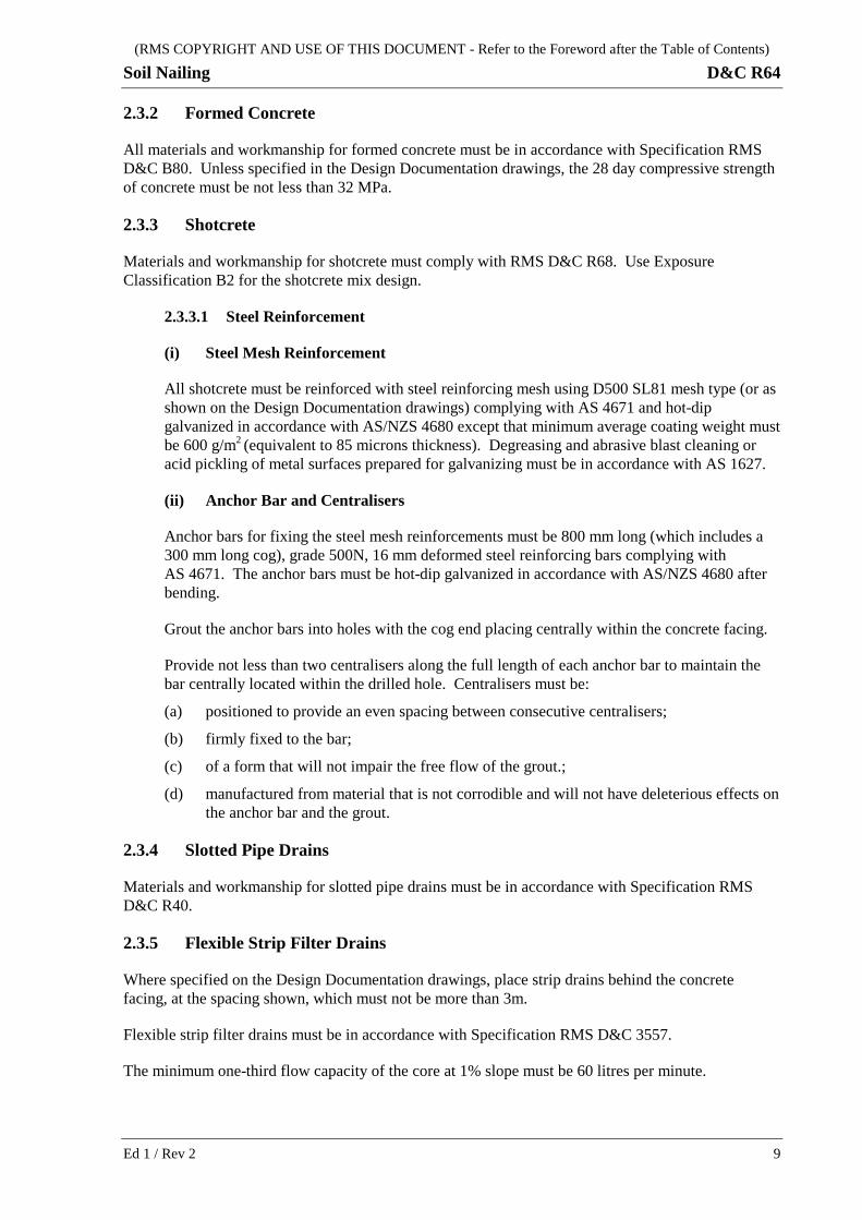
2.3.2 Formed Concrete
All materials and workmanship for formed concrete must be in accordance with Specification RMS D&C B80. Unless specified in the Design Documentation drawings, the 28 day compressive strength of concrete must be not less than 32 MPa.
2.3.3 Shotcrete
Materials and workmanship for shotcrete must comply with RMS D&C R68. Use Exposure Classification B2 for the shotcrete mix design.
2.3.3.1 Steel Reinforcement
(i) Steel Mesh Reinforcement
All shotcrete must be reinforced with steel reinforcing mesh using D500 SL81 mesh type (or as shown on the Design Documentation drawings) complying with AS 4671 and hot-dip galvanized in accordance with AS/NZS 4680 except that minimum average coating weight must be 600 g/m2 (equivalent to 85 microns thickness). Degreasing and abrasive blast cleaning or acid pickling of metal surfaces prepared for galvanizing must be in accordance with AS 1627.
(ii) Anchor Bar and Centralisers
Anchor bars for fixing the steel mesh reinforcements must be 800 mm long (which includes a 300 mm long cog), grade 500N, 16 mm deformed steel reinforcing bars complying with AS 4671. The anchor bars must be hot-dip galvanized in accordance with AS/NZS 4680 after bending.
Grout the anchor bars into holes with the cog end placing centrally within the concrete facing.
Provide not less than two centralisers along the full length of each anchor bar to maintain the bar centrally located within the drilled hole. Centralisers must be:
(a) positioned to provide an even spacing between consecutive centralisers;
(b) firmly fixed to the bar;
(c) of a form that will not impair the free flow of the grout.;
(d) manufactured from material that is not corrodible and will not have deleterious effects on the anchor bar and the grout.
2.3.4 Slotted Pipe Drains
Materials and workmanship for slotted pipe drains must be in accordance with Specification RMS D&C R40.
2.3.5 Flexible Strip Filter Drains
Where specified on the Design Documentation drawings, place strip drains behind the concrete facing, at the spacing shown, which must not be more than 3m.
Flexible strip filter drains must be in accordance with Specification RMS D&C 3557.
The minimum one-third flow capacity of the core at 1% slope must be 60 litres per minute.
Ed 1 / Rev 2 9
(RMS COPYRIGHT AND USE OF THIS DOCUMENT - Refer to the Foreword after the Table of Contents)
D&C R64 Soil Nailing
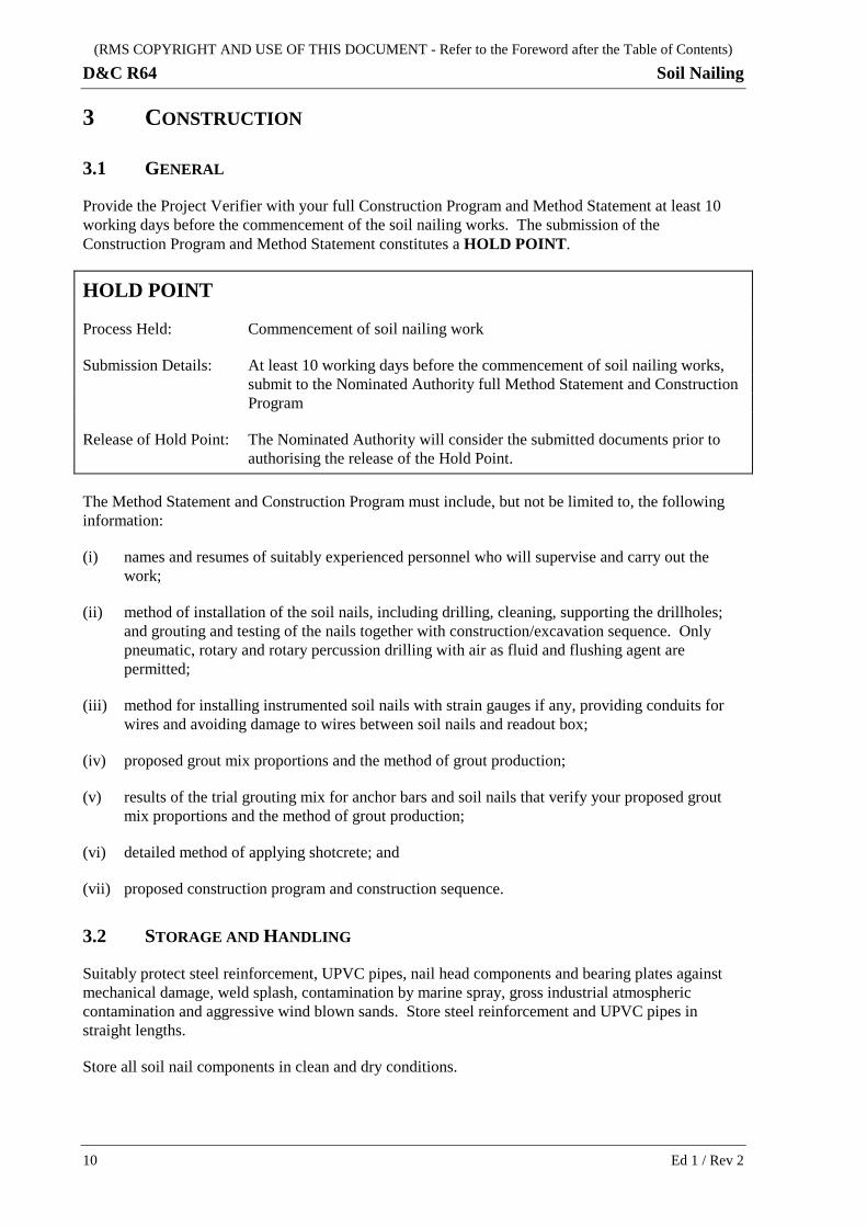
3 CONSTRUCTION
3.1 GENERAL
Provide the Project Verifier with your full Construction Program and Method Statement at least 10 working days before the commencement of the soil nailing works. The submission of the Construction Program and Method Statement constitutes a HOLD POINT.
HOLD POINT
Process Held: Commencement of soil nailing work
Submission Details: At least 10 working days before the commencement of soil nailing works, submit to the Nominated Authority full Method Statement and Construction Program
Release of Hold Point: The Nominated Authority will consider the submitted documents prior to authorising the release of the Hold Point.
The Method Statement and Construction Program must include, but not be limited to, the following information:
(i) names and resumes of suitably experienced personnel who will supervise and carry out the work;
(ii) method of installation of the soil nails, including drilling, cleaning, supporting the drillholes; and grouting and testing of the nails together with construction/excavation sequence. Only pneumatic, rotary and rotary percussion drilling with air as fluid and flushing agent are permitted;
(iii) method for installing instrumented soil nails with strain gauges if any, providing conduits for wires and avoiding damage to wires between soil nails and readout box;
(iv) proposed grout mix proportions and the method of grout production;
(v) results of the trial grouting mix for anchor bars and soil nails that verify your proposed grout mix proportions and the method of grout production;
(vi) detailed method of applying shotcrete; and
(vii) proposed construction program and construction sequence.
3.2 STORAGE AND HANDLING
Suitably protect steel reinforcement, UPVC pipes, nail head components and bearing plates against mechanical damage, weld splash, contamination by marine spray, gross industrial atmospheric contamination and aggressive wind blown sands. Store steel reinforcement and UPVC pipes in straight lengths.
Store all soil nail components in clean and dry conditions.
10 Ed 1 / Rev 2
(RMS COPYRIGHT AND USE OF THIS DOCUMENT - Refer to the Foreword after the Table of Contents)
Soil Nailing D&C R64
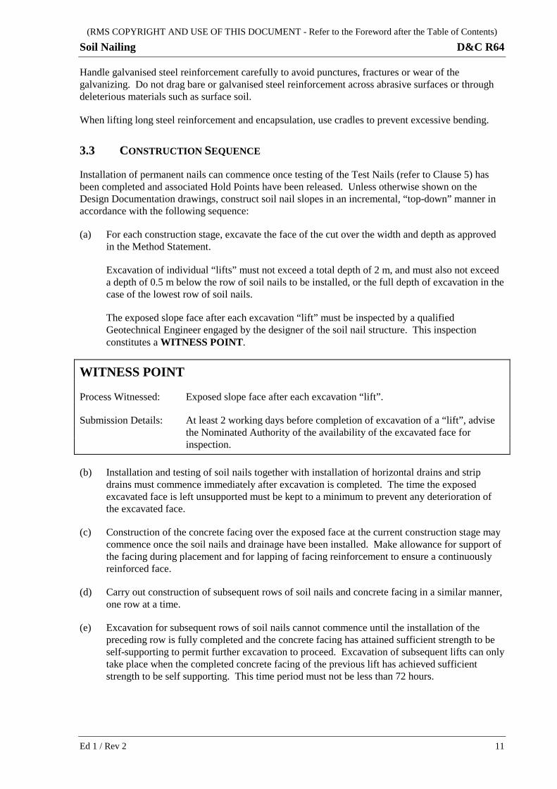
Handle galvanised steel reinforcement carefully to avoid punctures, fractures or wear of the galvanizing. Do not drag bare or galvanised steel reinforcement across abrasive surfaces or through deleterious materials such as surface soil.
When lifting long steel reinforcement and encapsulation, use cradles to prevent excessive bending.
3.3 CONSTRUCTION SEQUENCE
Installation of permanent nails can commence once testing of the Test Nails (refer to Clause 5) has been completed and associated Hold Points have been released. Unless otherwise shown on the Design Documentation drawings, construct soil nail slopes in an incremental, “top-down” manner in accordance with the following sequence:
(a) For each construction stage, excavate the face of the cut over the width and depth as approved in the Method Statement.
Excavation of individual “lifts” must not exceed a total depth of 2 m, and must also not exceed a depth of 0.5 m below the row of soil nails to be installed, or the full depth of excavation in the case of the lowest row of soil nails.
The exposed slope face after each excavation “lift” must be inspected by a qualified Geotechnical Engineer engaged by the designer of the soil nail structure. This inspection constitutes a WITNESS POINT.
WITNESS POINT
Process Witnessed: Exposed slope face after each excavation “lift”.
Submission Details: At least 2 working days before completion of excavation of a “lift”, advise the Nominated Authority of the availability of the excavated face for inspection.
(b) Installation and testing of soil nails together with installation of horizontal drains and strip drains must commence immediately after excavation is completed. The time the exposed excavated face is left unsupported must be kept to a minimum to prevent any deterioration of the excavated face.
(c) Construction of the concrete facing over the exposed face at the current construction stage may commence once the soil nails and drainage have been installed. Make allowance for support of the facing during placement and for lapping of facing reinforcement to ensure a continuously reinforced face.
(d) Carry out construction of subsequent rows of soil nails and concrete facing in a similar manner, one row at a time.
(e) Excavation for subsequent rows of soil nails cannot commence until the installation of the preceding row is fully completed and the concrete facing has attained sufficient strength to be self-supporting to permit further excavation to proceed. Excavation of subsequent lifts can only take place when the completed concrete facing of the previous lift has achieved sufficient strength to be self supporting. This time period must not be less than 72 hours.
Ed 1 / Rev 2 11
(RMS COPYRIGHT AND USE OF THIS DOCUMENT - Refer to the Foreword after the Table of Contents)
D&C R64 Soil Nailing
3.4 SOIL NAIL INSTALLATION
3.4.1 General
Installation of the soil nails must be carried out by qualified and experienced personnel.
Assemble the soil nail (with or without encapsulation) in a workshop, or on site under cover, by trained personnel. Identify the assembled soil nails using clear markings and handle them with care.
3.4.2 Set Out and Drilling
Use rotary or rotary-percussion drilling equipment for drilling to ensure minimal remoulding of insitu materials within the drillholes. Do not use drilling fluids other than air.
Holes for galvanised soil nails must be at least 100 mm in diameter or as shown on the Design Documentation drawings.
During the drilling operation, record the ground conditions encountered on a drillhole log together with all changes in ground type and notes on water levels encountered and drilling rates. Record also on the drillhole log the bearing and inclination of the formed drillhole as well as geometric details and the cleaning procedure.
On completion of drilling, clean the drillhole of all loose and deleterious material and protect or seal the drillhole opening to prevent the entry of foreign matter. Carry out cleaning by flushing with air or compressed air using side jet bits, so as to ensure removal of all drill cuttings from the walls and bottom of the drillhole and to avoid excessive air pressure. Reinforcement may only be installed in a clean hole free of debris and foreign matter.
The drillholes for the soil nails must have adequate clearance from the nearby structures and be constructed within the following tolerances:
(a) Deviation in alignment of the drillhole must not exceed 5°. Deviation from straight must not exceed 25 mm in any 1.5 m length of hole. Locate the entry point of the drillholes within ±50 mm of its design position on the cut face;
(b) The depth of the holes must be within a tolerance of –0, +100 mm;
(c) An allowance for overdrilling (300 mm maximum) must be added to the depth where debris cannot be removed from the bottom of the hole;
(d) The maximum deviation of the diameter of the drillholes from the design diameter is –0, +10 mm.
3.4.3 Insertion and Grouting
3.4.3.1 Insertion of Soil Nails
Prior to soil nail installation, clean the drillhole of debris by air flushing methods.
Insert soil nails in one careful operation at a controlled rate to avoid dislodgment of material from the wall of the drillhole and to ensure that centralisers and spacers are not displaced. Replace any soil nail or its galvanised coating which is damaged during installation. Insertion and grouting must occur as soon as practicable following drilling, but in any event must be completed within 24 hours after completion of drilling.
12 Ed 1 / Rev 2
(RMS COPYRIGHT AND USE OF THIS DOCUMENT - Refer to the Foreword after the Table of Contents)
Soil Nailing D&C R64
3.4.3.2 Grouting Equipment
Grouting equipment for soil nail installation must be of a type, quantity and size which is suitable for the grouting required. Keep the equipment clean and in good working order.
The equipment must include:
(a) a purpose designed high speed mechanical stirrer capable of producing grout free of lumps within a mixing time of 2 minutes. Mixers must be fitted with a water volume measuring device for batching purposes;
(b) a holding tank fitted with an agitator to provide continuous agitation of the grout at 100 rpm. The tank must be fitted with a dipstick to allow continuous measurement of the volume of grout in the tank;
(c) flow meter and pressure gauge to check the intake grout volume and the required pressure.
The pump used for grout injection must be of the positive displacement type (i.e. it must be actuated by a piston or screw) fitted with a bypass back to the agitator tank to allow a standby pump to be brought into operation immediately in the event of breakdowns during grouting operations.
3.4.3.3 Grout Mixing
Batching of the dry materials must be by weight. Measure the amount of water used with a calibrated flowmeter or a measuring tank.
Mix the grout by adding initially approximately two-thirds of cement to the water, followed by the additive if any, and then the remaining one-third of cement. Mix the grout for a sufficient time to produce a grout of uniform consistency.
The grout mixing process must utilise a recirculating system where the grout is continuously discharged and recharged into the mixing unit during the mixing period. After mixing, keep the grout continuously agitated.
Pass the grout through a nominal 1.2 mm wire cloth to ensure a uniformly mixed grout prior to injection. Use the grout as soon as possible after mixing and in any case within 30 minutes of adding cement, unless approved retarding agents are used.
Grout pumps must be efficient and capable of running continuously for the duration of the grouting operation. They must be capable of pumping the specified grout at a rate appropriate to that required for the operation.
3.4.3.4 Grouting
Carry out grouting by use of supply lines directly connecting the pumps to the down-hole grout tubes. Inject grout through a grout tube to the bottom of the hole, at an injection pressure of not more than twice the overburden pressure measured at the top of the soil nail. The grout tubes must have a minimum internal diameter of 12 mm to ensure that blockages will not occur during grouting operations and must also be sufficiently robust to ensure that they are not damaged during handling.
During the grouting operation, the grout must displace all air and water and fill the hole in a continuous operation until the emerging grout is of the same consistency as the grout being
Ed 1 / Rev 2 13
(RMS COPYRIGHT AND USE OF THIS DOCUMENT - Refer to the Foreword after the Table of Contents)
D&C R64 Soil Nailing
pumped in. The grout level must then be checked by sitting for 5 minutes and top-up grout introduced if necessary to ensure that the soil nail is fully grouted.
Plug the remaining void at the top of the drillhole flush to the slope faces using a dry-packed 3:1 sand:cement mix. Discard and dispose of the grout that has overflowed from the hole as waste.
Alternative methods to ensure that soil nails are fully grouted may include overpouring the grout using a PVC tube extended sufficiently to allow for grout losses and prevent the formation of a horizontal construction joint in the grout. The choice of method must be adapted to the geology of the material and the extent of grout loss encountered. The degree of rock fracturing or presence of fill will affect grout loss.
During grouting of encapsulated soil nail, install a separated grout tube extending to the bottom of the assembly both inside and outside the encapsulation. Inject grout in a controlled manner from the bottom to the top both outside and inside until the encapsulation is completely filled without separation. Maintain the grout level between the outside and the inside sheathing to not greater than 1 m to ensure minimal pressure variation across the sheathing.
Discontinue grouting if the ambient and grout temperature falls below 5°C.
Protect the soil nail from accidental disturbance after grouting has been completed to ensure that damage of the grout/soil and grout/nail bond does not occur.
3.4.3.5 Loss or Leakage of Grout
If, during the grouting of any hole, grout is found to flow from adjacent grout holes in quantities sufficient to interfere seriously with the grouting operation or to cause appreciable loss of grout, cap the adjacent holes temporarily and remove the steel reinforcement bar from the grouted hole. Grout, re-drill and re-grout the hole.
If, during the grouting of any hole, grout is found to flow from joints in the geological formation at the Construction Site or any other locations, plug or caulk the leaks in a manner acceptable to the RMS Representative.
3.4.3.6 Bleed Testing
Provide one sample of grout from each batch of grout to determine the amount of bleeding in accordance with ASTM C940 and the requirements specified in Clause 2.2.7.
Samples must be provided not more than 30 minutes after the grout has been mixed and must be protected from moisture content changes before the tests for amount of bleeding are carried out.
3.4.3.7 Fluidity Testing
Provide one sample of grout from each batch of grout to determine the fluidity in accordance with ASTM C939 and the requirements specified in Clause 2.2.7.
3.4.3.8 Compressive Strength Test
During the production of grout, take representative test specimens comprising cubes in accordance with Test Method RMS T375 at the frequencies shown in Table R64.2 below, and additional cubes if testing is required at ages other than seven days. Store cubes under standard curing conditions of 23°C and 100% relative humidity, in accordance with Test Method RMS T375.
14 Ed 1 / Rev 2
(RMS COPYRIGHT AND USE OF THIS DOCUMENT - Refer to the Foreword after the Table of Contents)
Soil Nailing D&C R64
Table R64.2 – Sampling Frequency of Test Specimens
Grout Batches Sampling Frequency
1 batch/day 1 pair of cubes
2 batches/day 2 pairs of cubes
3 – 5 batches/day 3 pairs of cubes
6 – 10 batches/day 4 pairs of cubes
Grout cubes must be tested at 7 days in accordance with Test Method RMS T375 and must achieve the compressive strength specified in Clause 2.2.7.
If the result of any test for compressive strength of grout does not comply with the specified requirements, submit particulars of the proposed changes to the materials, grout mix or methods of production to the Project Verifier, make further trial mixes and carry out further grouting trials. Down-rate the capacity of the soil nails comprising the batch and install additional nails if necessary.
3.4.3.9 Fitting of Galvanised Nuts and Bearing Plates
Fit the bearing plate at the head of the soil nail concentrically to the steel reinforcement with a tolerance of 5 mm and perpendicular to the steel reinforcement with a tolerance of 3°.
The methods used for bedding the bearing plate must ensure void-free contact over the full area of the plate.
After the grout has attained a minimum compressive strength of 32 MPa, lock tight the nuts on soil nails.
3.4.3.10 Construction Conformity Record
Submit conformity records for each soil nail installation. The record must include the following:
(a) soil nail identification number;
(b) bearing, inclination, position, depth, and diameter of the formed drillhole;
(c) soil/rock type encountered with depth during drilling;
(d) water levels;
(e) drilling rates;
(f) cleaning procedure;
(g) type and age of cement;
(h) concentration and type of additive (if any);
(i) water/cement ratio;
(j) bleed characteristics of grout;
(k) mixing equipment used;
(l) mixing time;
(m) size of grout pipe and length;
Ed 1 / Rev 2 15
(RMS COPYRIGHT AND USE OF THIS DOCUMENT - Refer to the Foreword after the Table of Contents)
D&C R64 Soil Nailing
(n) method of grouting;
(o) time intervals between completion of soil nail hole drilling and start of grout injection;
(p) time of completing grout injection;
(q) volume of grout injected;
(r) average injection pressure;
(s) times and details of any interruptions;
(t) test specimens taken and 7 day grout strength obtained;
(u) estimated elastic extension for Suitability Test and Acceptance Tests.
4 INSTRUMENTED SOIL NAIL Where specified on the Design Documentation drawings, install instrumented soil nails with attached strain gauges. Refer to Annexure R64/E for a diagram of a typical soil nail structure with instrumentation, and typical soil nail instrumentation requirements.
Instrumented soil nails with attached strain gauges are installed to measure axial forces on the nails. The objective of the instrumentation is to ensure that the structure performs within the design requirements by measurement of tensile forces on selected soil nail bars.
The work must be carried out by a third party geotechnical instrumentation specialist with proven experience in this type of work.
Instrumentation plans are to be included in the Design Documentation drawings, including the location for the terminal box and concrete foundation pad.
Supply the instrumented soil nails at least 21 days before the commencement of soil nail installation. Protect and store these soil nails to prevent any damage to the gauges or associated cabling. Properly label each instrumented soil nail and identify its location (row and cross section detail).
Insert the instrumented soil nail into the borehole carefully to avoid damaging the strain gauges and do not grout the borehole until the strain gauge circuits at the readout box have been tested.
Progressively install 100 mm PVC tubes (containing the draw wires) in a trench to the readout box, as shown on the Design Documentation drawings. Connect the clearly labelled wires to the readout box with the correct soil nail number and strain gauge location. Provide electric power necessary to operate the readout box for the monitoring of soil nail instrumentation installed. Provide unrestricted and safe access throughout the project for testing the instrumentation.
5 TESTING OF SOIL NAILS
5.1 GENERAL
Soil nails must undergo two types of testing, namely, Suitability Test for test nails and Acceptance Test for permanent nails.
The purpose of Suitability Test on test nails is to confirm that the bond strength is achieved and that the reinforcement will perform as designed prior to permanent soil nail installation. The Acceptance
16 Ed 1 / Rev 2
(RMS COPYRIGHT AND USE OF THIS DOCUMENT - Refer to the Foreword after the Table of Contents)
Soil Nailing D&C R64
Test on permanent nails is a measure of quality control. Carry out tests for soil nails under the direction of a qualified and experienced engineer provided by you in the presence of your authorised representative who must record the work.
The number of test nails to be assessed by Suitability Test must be the greater of:
(i) the number specified on the Design Documentation drawings; or
(ii) 1% of the permanent nails but not less than 2.
Subject a total of 3% of permanent nails to Acceptance Test (Clause 5.2.2).
The locations of the test nails must be approved by the Project Verifier.
5.2 SOIL NAIL TESTS
5.2.1 Suitability Test
Prior to the installation of permanent nails, install Suitability Test nails. The tests must establish adequacy of the soil nail installation with respect to bond stresses between the nail and soil for the various ground conditions which apply and must involve subjecting soil nails to axial pull-out loads until failure occurs, or to 80% of the ultimate tensile strength (UTS) of the soil nail bar.
These nails must have a minimum bond length of 3 m unless otherwise shown on the Design Documentation drawings. Provide a minimum debonded zone of 1 m length of soil nail immediately behind the facing in order to prevent influence on the test result from the load test reaction system. This debonded length requirement may be waived if the load test reaction system will not exert any pressure on the slope surface within a metre radius from the circumference of the test nail drill hole.
The soil nails subject to Suitability Test are additional to the permanent nails shown on the Design Documentation drawings.
Submit to the Project Verifier testing arrangements to suit your particular working method and equipment, and calculations to verify load transfer, reactions and load testing programme, in conjunction with actual Suitability Test bar extensions and adjusted extensions deducting the calculated elastic bar extension.
Give the Project Verifier at least one working day notice of your intention to carry out Suitability Test.
Test the soil nails subject to Suitability Test to pull-out failure or to 200% of the design working load, whichever is lower.
Adjust the reinforced bar diameter or strength grade, if necessary, to ensure that the test load does not exceed 80% of the UTS of the soil nail bar. The test nails must be installed in an identical manner, including time delays between various operations, and at locations with ground conditions representative of that of the permanent nails.
Injected grout must have achieved a compressive strength of 40 MPa before performing the Suitability Test.
Soil nails subjected to Suitability Tests must be loaded in the working load increments and held at these loads for the period specified in Table R64.3 below:
Ed 1 / Rev 2 17
(RMS COPYRIGHT AND USE OF THIS DOCUMENT - Refer to the Foreword after the Table of Contents)
D&C R64 Soil Nailing
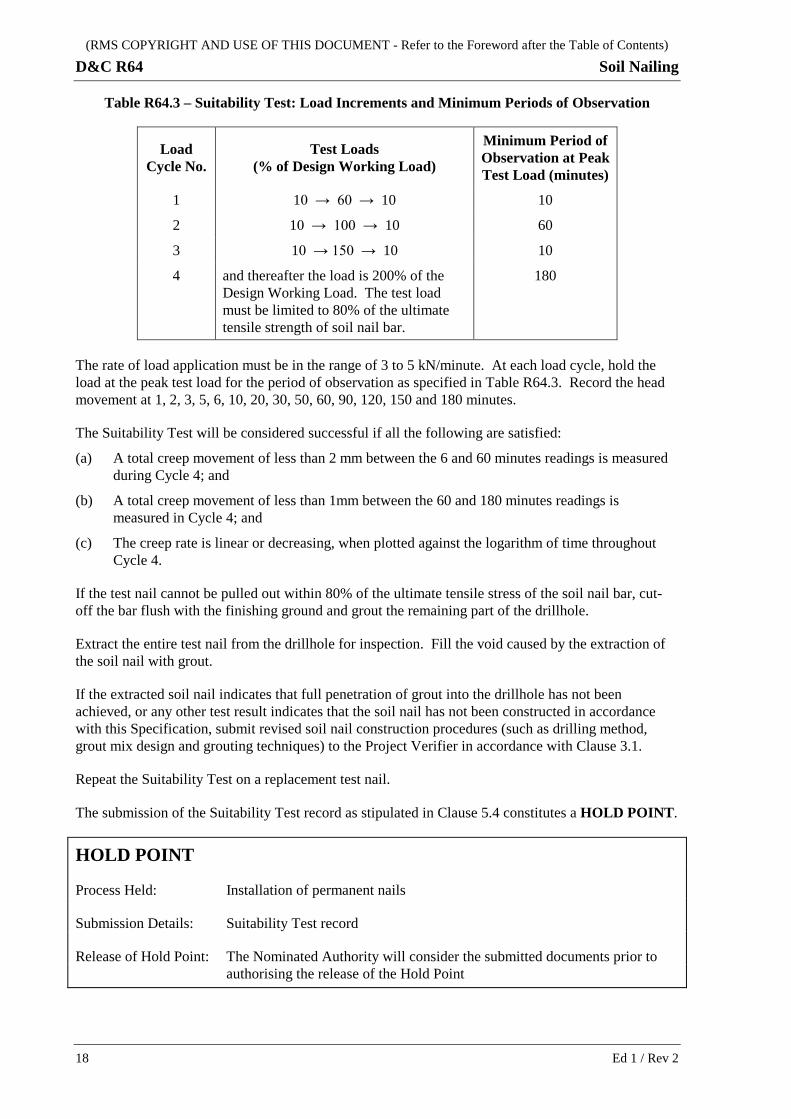
Table R64.3 – Suitability Test: Load Increments and Minimum Periods of Observation
Load Cycle No.
Test Loads (% of Design Working Load)
Minimum Period of Observation at Peak Test Load (minutes)
1 10 → 60 → 10 10
2 10 → 100 → 10 60
3 10 → 150 → 10 10
4 and thereafter the load is 200% of the Design Working Load. The test load must be limited to 80% of the ultimate tensile strength of soil nail bar.
180
The rate of load application must be in the range of 3 to 5 kN/minute. At each load cycle, hold the load at the peak test load for the period of observation as specified in Table R64.3. Record the head movement at 1, 2, 3, 5, 6, 10, 20, 30, 50, 60, 90, 120, 150 and 180 minutes.
The Suitability Test will be considered successful if all the following are satisfied:
(a) A total creep movement of less than 2 mm between the 6 and 60 minutes readings is measured during Cycle 4; and
(b) A total creep movement of less than 1mm between the 60 and 180 minutes readings is measured in Cycle 4; and
(c) The creep rate is linear or decreasing, when plotted against the logarithm of time throughout Cycle 4.
If the test nail cannot be pulled out within 80% of the ultimate tensile stress of the soil nail bar, cut-off the bar flush with the finishing ground and grout the remaining part of the drillhole.
Extract the entire test nail from the drillhole for inspection. Fill the void caused by the extraction of the soil nail with grout.
If the extracted soil nail indicates that full penetration of grout into the drillhole has not been achieved, or any other test result indicates that the soil nail has not been constructed in accordance with this Specification, submit revised soil nail construction procedures (such as drilling method, grout mix design and grouting techniques) to the Project Verifier in accordance with Clause 3.1.
Repeat the Suitability Test on a replacement test nail.
The submission of the Suitability Test record as stipulated in Clause 5.4 constitutes a HOLD POINT.
HOLD POINT
Process Held: Installation of permanent nails
Submission Details: Suitability Test record
Release of Hold Point: The Nominated Authority will consider the submitted documents prior to authorising the release of the Hold Point
18 Ed 1 / Rev 2
(RMS COPYRIGHT AND USE OF THIS DOCUMENT - Refer to the Foreword after the Table of Contents)
Soil Nailing D&C R64
5.2.2 Acceptance Test
A total of 3% of permanent nails must be subjected to Acceptance Test. Of these, half must be in the top row, a quarter in the middle row and a quarter in the bottom row. The Geotechnical Design Representative will nominate the locations of soil nails subject to Acceptance Test. Additional locations for Acceptance Test maybe required.
Provide a minimum debonded zone of 1 m length of soil nail immediately behind the facing in order to prevent influence on the test result from the load test reaction system. This debonded length requirement may be waived if the load test reaction system will not exert any pressure on the slope surface within a metre radius from the circumference of the test nail drill hole.
Carry out Acceptance Test in the presence of the Project Verifier prior to the application of concrete facing to the exposed ground.
Injected grout must have achieved a compressive strength of 40 MPa before performing Acceptance Test.
The maximum applied load during the acceptance test must not exceed 80% of the ultimate tensile strength of the soil nail bar.
Provide actual acceptance test bar extensions and adjusted extensions deducting the calculated elastic bar extension.
Soil nails subject to acceptance tests must be loaded to the load increments and held at these loads for the periods specified in Table R64.4 below:
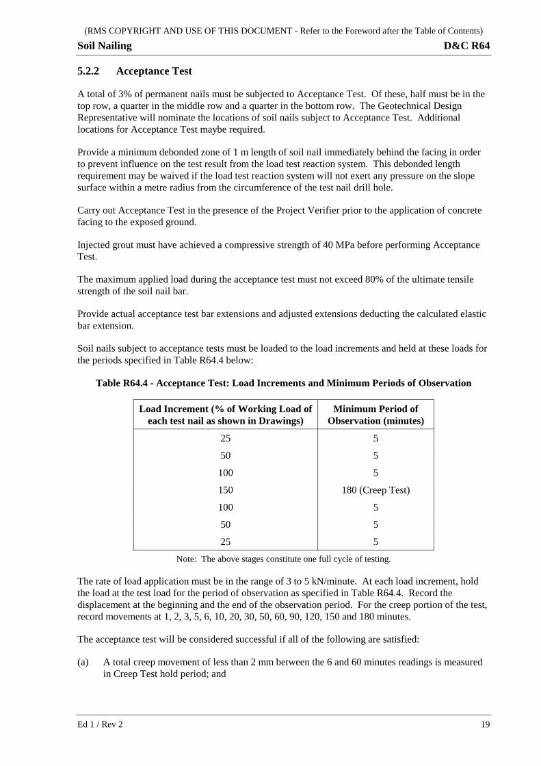
Table R64.4 - Acceptance Test: Load Increments and Minimum Periods of Observation
Load Increment (% of Working Load of each test nail as shown in Drawings)
Minimum Period of Observation (minutes)
25 5
50 5
100 5
150 180 (Creep Test)
100 5
50 5
25 5
Note: The above stages constitute one full cycle of testing.
The rate of load application must be in the range of 3 to 5 kN/minute. At each load increment, hold the load at the test load for the period of observation as specified in Table R64.4. Record the displacement at the beginning and the end of the observation period. For the creep portion of the test, record movements at 1, 2, 3, 5, 6, 10, 20, 30, 50, 60, 90, 120, 150 and 180 minutes.
The acceptance test will be considered successful if all of the following are satisfied:
(a) A total creep movement of less than 2 mm between the 6 and 60 minutes readings is measured in Creep Test hold period; and
Ed 1 / Rev 2 19
(RMS COPYRIGHT AND USE OF THIS DOCUMENT - Refer to the Foreword after the Table of Contents)
D&C R64 Soil Nailing
(b) A total creep movement of less than 1 mm between the 60 and 180 minutes readings is measured in Creep Test hold period; and
(c) The creep rate is linear or decreasing, when plotted against the logarithm of time throughout Creep Test hold period.
Where a test nail does not meet the acceptance criteria, test an additional 2 soil nails in the vicinity of the nonconforming soil nail. If any soil nail fails an Acceptance Test, abandon the soil nail and completely remove it from the drillhole. Fill the drillhole by grouting. If the failed soil nail cannot be pulled out within 80% of the UTS of the soil nail bar, cut-off the bar flush with the finishing ground and grout the remaining part of the drillhole. Install another soil nail adjacent to the abandoned one for additional test.
5.3 TESTING AND MEASURING EQUIPMENT
Measure displacements using two dial gauges mounted on a tripod or fixed to a rigid support that is independent of the jacking mechanism and the soil nail. The dial gauge must be capable of measuring to an accuracy of 0.01 mm. Dial gauges must be set up so as to avoid any misalignment and eccentricity to the direction of movement of the soil nail, and zeroed after alignment and initial load has been applied.
Establish a stable datum to measure the movement at the bar head. Measure movements of the bar head relative to the datum to an accuracy of ±0.1 mm.
Use a hydraulic jack, with a minimum travel of 150 mm, to apply the load. Apply the load to the soil nail via a load bridge to ensure that the surface reaction is clear of the soil nail. Measure the test load with an accuracy of ±1 kN. Add a centre hole load cell in series with the jack for use during tests.
Calibrate the hydraulic jack, pressure gauge and load cell as a set. Obtain calibration certificates, which must be less than 12 months old, for the jack, pressure gauge and load cell prior to the soil nail testing. The calibration must be undertaken by a registered NATA laboratory. The identification numbers on the field test equipment must match the identification numbers on the calibration data sheets. Ensure that the load cell is properly aligned with the axis of the soil nail bar and the jack.
The calibration certificate must be accompanied by the related calibration curve and tabulated record of hydraulic pressure against jack load. Perform the calibration for the loading and unloading operations of the jack over its full working range.
Submit details of the installation, load measuring and movement measuring devices and the method of calculating/defining the bar elastic extension, to the Project Verifier.
5.4 RECORDS OF TESTS
Keep records of any Suitability Test and Acceptance Test carried out. These records must include:
(a) Date;
(b) Soil nail number;
(c) Number of tests carried out;
(d) Load/ extension measurements;
(e) Any variations from the specified procedure;
(f) Details of test results;
20 Ed 1 / Rev 2
(RMS COPYRIGHT AND USE OF THIS DOCUMENT - Refer to the Foreword after the Table of Contents)
Soil Nailing D&C R64
(g) Any unforeseen or unusual conditions encountered;
(h) Time intervals between completion of test soil nail hole, drilling and start of grout injection;
(i) Actual and calculated bar extensions, including and excluding elastic bar extension.
Tabulate and plot the soil nail head and bearing plate movements on a graph for assessment together with all other relevant information.
Submission of the testing records for the test nails constitutes a HOLD POINT.
HOLD POINT
Process Held: Acceptance of permanent nails
Submission Details: Within one week of completion, submit to the Nominated Authority test results on permanent nails in a prior agreed format
Release of Hold Point: The Nominated Authority will consider the submitted documents prior to authorising the release of the Hold Point
6 PLACEMENT OF CONCRETE FACING
6.1 GENERAL
Construct the concrete facing either from formed concrete or shotcrete, and reinforced with galvanised steel mesh/bars as shown on the Design Documentation drawings.
Place formed concrete in accordance with Specification RMS D&C B80.
Place shotcrete in accordance with Specification RMS D&C R68.
6.2 SLOPE SURFACE PREPARATION
Carry out slope surface preparation in accordance with RMS D&C R68.
During placement of concrete, protect the drainage system against contamination to ensure proper functioning.
Install thickness measuring pins on a 1.5 m square grid with a minimum 75 mm cover to reinforcement. These must be durable, non-corrosive and of sufficient length to provide adequate fixity during application of formed concrete or shotcrete.
Firmly fix steel reinforcement to prevent movement and vibration while the shotcrete is being applied.
6.3 DRILLING AND GROUTING OF STEEL MESH SUPPORT ANCHOR BARS
Give at least one working day notice of your intention to commence drilling of the steel anchor bar holes to support steel mesh.
Ed 1 / Rev 2 21
(RMS COPYRIGHT AND USE OF THIS DOCUMENT - Refer to the Foreword after the Table of Contents)
D&C R64 Soil Nailing
Each anchor bar hole may be sealed until the anchor bar is ready to be installed to prevent the entry of foreign matter.
Immediately prior to installing the bar, clean the walls of the drillhole into which it is to be installed of all deleterious materials or accumulations, which would impair the effectiveness of the anchor bar. Following cleaning, gauge the hole to confirm that it is unobstructed for the full depth and diameter.
The anchor bar and centralisers must be assembled and positioned in the hole in accordance with the requirements of this Specification.
All grouting operations must be carried out by personnel skilled and experienced in this type of work.
The grouting supervisor must inspect the anchor bars assemblies prior to installation and verify that bars and grouting tubes have been correctly installed.
6.4 APPLICATION OF SHOTCRETE
6.4.1 General
Application of shotcrete must be in accordance with RMS D&C R68.
Apply shotcrete in successive layers not exceeding 75 mm in thickness and with adequate adhesion to the surface or previous layers of shotcrete to prevent slumping or sagging. Unless approved otherwise, complete shotcreting to a whole panel (preferably not less than 10 m in length) prior to shotcreting the next panel.
Protect adjoining rock areas not required to be shotcreted from splash and spray rebound. Remove splash or rebound material on these adjoining surfaces by air-water jet or other suitable means as work proceeds.
Shotcrete must not cover or impair the function of slotted pipe drain or strip drain outlets which protrude through the shotcrete layer. You may use temporary plugs to protect such outlets during the shotcreting process.
6.4.2 Construction Joints
Keep construction joints to a minimum.
Form construction joints by one of the following methods:
(a) Placing or trimming the joint edge not more than 45° with the base;
(b) Forming an approximately square joint to part depth by placing the shotcrete against a former or making a cut to the depth of the reinforcement; or
(c) Forming a full-depth square joint placed against a former.
Where a 30° taper is adopted for a construction joint, it must not be used as an end of day joint. Such tapered joints must be thoroughly cleaned and wetted by air water jet before continuing application of the adjoining shotcrete layer.
Taper the shotcrete over approximately 500 mm from the edges of the mesh (where used). Completely backfill any cut back areas with the final layer of shotcrete flush with the adjacent slope face.
22 Ed 1 / Rev 2
(RMS COPYRIGHT AND USE OF THIS DOCUMENT - Refer to the Foreword after the Table of Contents)
Soil Nailing D&C R64
6.4.3 Curing of Shotcrete
Carry out curing of shotcrete in accordance with RMS D&C R68.
6.4.4 Testing of Shotcrete
Carry out testing of shotcrete for conformity in accordance with RMS D&C R68.
Holes created by removal of cores must be thoroughly cleaned and dampened and reinstated with mortar (or other approved product) to achieve the same durability as the shotcrete.
6.4.5 Checking Integrity of Shotcrete
Check the integrity of the shotcrete for hollow areas by sounding with a hammer not more than 24 hours after placement.
Rectify defective areas by removal and replacement with fresh material with the area to be treated being a minimum of 300 mm x 300 mm. Remove and replace shotcrete which lacks uniformity, exhibits segregation, honeycombing, or lamination or shows evidence of other defects (e.g. dry patches, sand pockets or sagged slumped material) with fresh shotcrete.
7 RECORDS FOR INSTALLATION Submit records for the installation of anchor bars, strip drains, steel reinforcement and shotcrete test records within three working days of completion of installation. Within the said three working days from completion of installation and after submission of conformity records, present the slope area to be covered by shotcrete to the Project Verifier for inspection.
Ed 1 / Rev 2 23
(RMS COPYRIGHT AND USE OF THIS DOCUMENT - Refer to the Foreword after the Table of Contents)
D&C R64 Soil Nailing
ANNEXURES R64/A TO R64/B – (NOT USED)
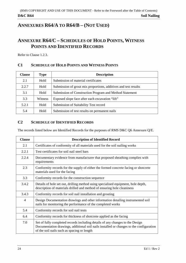
ANNEXURE R64/C – SCHEDULES OF HOLD POINTS, WITNESS POINTS AND IDENTIFIED RECORDS
Refer to Clause 1.2.3.
C1 SCHEDULE OF HOLD POINTS AND WITNESS POINTS
Clause Type Description
2.1 Hold Submission of material certificates
2.2.7 Hold Submission of grout mix proportions, additives and test results
3.1 Hold Submission of Construction Program and Method Statement
3.3 Witness Exposed slope face after each excavation “lift”
5.2.1 Hold Submission of Suitability Test record
5.4 Hold Submission of test results on permanent nails
C2 SCHEDULE OF IDENTIFIED RECORDS
The records listed below are Identified Records for the purposes of RMS D&C Q6 Annexure Q/E.
Clause Description of Identified Record
2.1 Certificates of conformity of all materials used for the soil nailing works
2.2.1 Test certificates for soil nail steel bars
2.2.4 Documentary evidence from manufacturer that proposed sheathing complies with requirements
2.3 Conformity records for the supply of either the formed concrete facing or shotcrete materials used for the facing
3.3 Conformity records for the construction sequence
3.4.2 Details of hole set out, drilling method using specialised equipment, hole depth, description of materials drilled and method of ensuring hole cleaniness
3.4.3 Conformity records for soil nail installation and grouting
4 Design Documentation drawings and other information detailing instrumented soil nails for monitoring the performance of the completed works
5.4 Conformity records for soil nail tests
6.4 Conformity records for thickness of shotcrete applied as the facing
7.0 Set of fully completed records including details of any changes to the Design Documentation drawings, additional soil nails installed or changes to the configuration of the soil nails such as spacing or length
24 Ed 1 / Rev 2
(RMS COPYRIGHT AND USE OF THIS DOCUMENT - Refer to the Foreword after the Table of Contents)
Soil Nailing D&C R64
ANNEXURE R64/D – PLANNING DOCUMENTS Refer to Clause 1.2.4.
The following documents are a summary of documents that must be included in the PROJECT QUALITY PLAN. The requirements of this Specification and others included in the deed must be reviewed to determine additional documentation requirements.
The information to be submitted as part of the PROJECT QUALITY PLAN must include, but is not limited to, the following:
(a) Nominated personnel to supervise and carry out the work together with evidence of relevant training and experience (Clause 3.1);
(b) Details of method of installation, grouting and testing of soil nails (Clauses 3.1, 3.4 and 5);
(c) Details of method of installation of instrumented soil nails with strain gauges (if any) (Clauses 3.1, 4 and Annexure R64/E);
(d) Proposed grout mix proportions, the method of grout production and the results of trial grouting mix (Clauses 2.2.7, 3.1 and 3.4.3.3);
(e) Details of method of applying shotcrete (Clause 3.1);
(f) Construction program and construction sequence including method of excavation and staging of works (Clauses 3.1 and 3.3);
(g) Details of method of storage and handling of soil nail components (Clause 3.2);
(h) Details of method of fitting of galvanised nuts and bearing plates (Clause 3.4.3.9).
Ed 1 / Rev 2 25
(RMS COPYRIGHT AND USE OF THIS DOCUMENT - Refer to the Foreword after the Table of Contents)
D&C R64 Soil Nailing
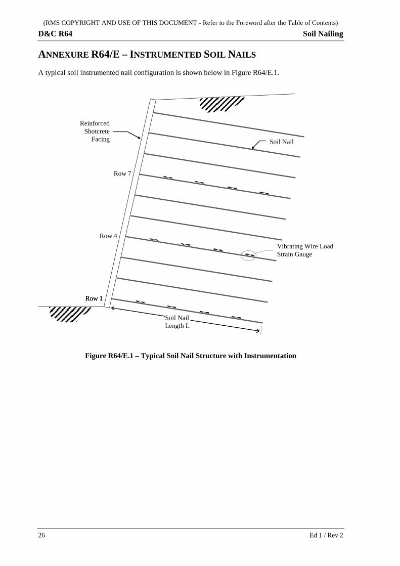
ANNEXURE R64/E – INSTRUMENTED SOIL NAILS A typical soil instrumented nail configuration is shown below in Figure R64/E.1.
Figure R64/E.1 – Typical Soil Nail Structure with Instrumentation
Row 1
Row 1
Row 4
Row 7
Vibrating Wire Load Strain Gauge
Soil Nail
Reinforced Shotcrete
Facing
Soil Nail Length L
26 Ed 1 / Rev 2
(RMS COPYRIGHT AND USE OF THIS DOCUMENT - Refer to the Foreword after the Table of Contents)
Soil Nailing D&C R64
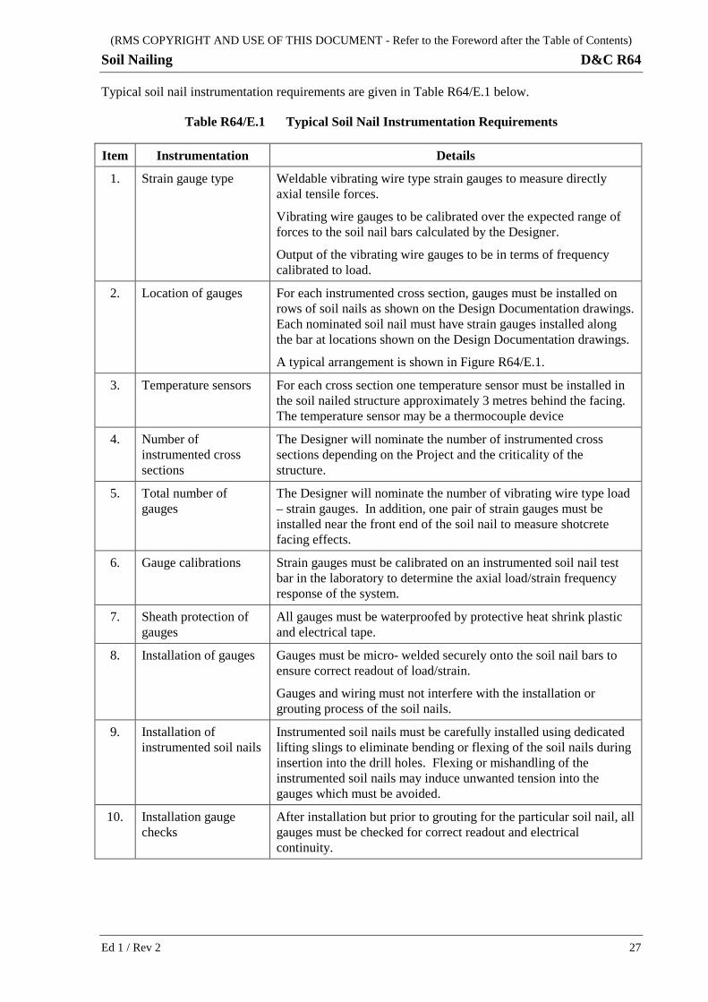
Typical soil nail instrumentation requirements are given in Table R64/E.1 below.
Table R64/E.1 Typical Soil Nail Instrumentation Requirements
Item Instrumentation Details
1. Strain gauge type Weldable vibrating wire type strain gauges to measure directly axial tensile forces.
Vibrating wire gauges to be calibrated over the expected range of forces to the soil nail bars calculated by the Designer.
Output of the vibrating wire gauges to be in terms of frequency calibrated to load.
2. Location of gauges For each instrumented cross section, gauges must be installed on rows of soil nails as shown on the Design Documentation drawings. Each nominated soil nail must have strain gauges installed along the bar at locations shown on the Design Documentation drawings.
A typical arrangement is shown in Figure R64/E.1.
3. Temperature sensors For each cross section one temperature sensor must be installed in the soil nailed structure approximately 3 metres behind the facing. The temperature sensor may be a thermocouple device
4. Number of instrumented cross sections
The Designer will nominate the number of instrumented cross sections depending on the Project and the criticality of the structure.
5. Total number of gauges
The Designer will nominate the number of vibrating wire type load – strain gauges. In addition, one pair of strain gauges must be installed near the front end of the soil nail to measure shotcrete facing effects.
6. Gauge calibrations Strain gauges must be calibrated on an instrumented soil nail test bar in the laboratory to determine the axial load/strain frequency response of the system.
7. Sheath protection of gauges
All gauges must be waterproofed by protective heat shrink plastic and electrical tape.
8. Installation of gauges Gauges must be micro- welded securely onto the soil nail bars to ensure correct readout of load/strain.
Gauges and wiring must not interfere with the installation or grouting process of the soil nails.
9. Installation of instrumented soil nails
Instrumented soil nails must be carefully installed using dedicated lifting slings to eliminate bending or flexing of the soil nails during insertion into the drill holes. Flexing or mishandling of the instrumented soil nails may induce unwanted tension into the gauges which must be avoided.
10. Installation gauge checks
After installation but prior to grouting for the particular soil nail, all gauges must be checked for correct readout and electrical continuity.
Ed 1 / Rev 2 27
(RMS COPYRIGHT AND USE OF THIS DOCUMENT - Refer to the Foreword after the Table of Contents)
D&C R64 Soil Nailing
Item Instrumentation Details
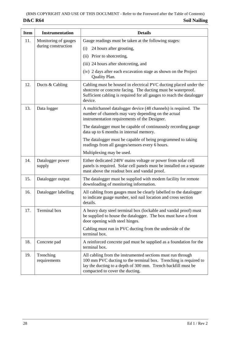
11. Monitoring of gauges during construction
Gauge readings must be taken at the following stages:
(i) 24 hours after grouting,
(ii) Prior to shotcreting,
(iii) 24 hours after shotcreting, and
(iv) 2 days after each excavation stage as shown on the Project Quality Plan.
12. Ducts & Cabling Cabling must be housed in electrical PVC ducting placed under the shotcrete or concrete facing. The ducting must be waterproof. Sufficient cabling is required for all gauges to reach the datalogger device.
13. Data logger A multichannel datalogger device (48 channels) is required. The number of channels may vary depending on the actual instrumentation requirements of the Designer.
The datalogger must be capable of continuously recording gauge data up to 6 months in internal memory.
The datalogger must be capable of being programmed to taking readings from all gauges/sensors every 6 hours.
Multiplexing may be used.
14. Datalogger power supply
Either dedicated 240V mains voltage or power from solar cell panels is required. Solar cell panels must be installed on a separate mast above the readout box and vandal proof.
15. Datalogger output The datalogger must be supplied with modem facility for remote downloading of monitoring information.
16. Datalogger labelling All cabling from gauges must be clearly labelled to the datalogger to indicate guage number, soil nail location and cross section details.
17. Terminal box A heavy duty steel terminal box (lockable and vandal proof) must be supplied to house the datalogger. The box must have a front door opening with steel hinges.
Cabling must run in PVC ducting from the underside of the terminal box.
18. Concrete pad A reinforced concrete pad must be supplied as a foundation for the terminal box.
19. Trenching requirements
All cabling from the instrumented sections must run through 100 mm PVC ducting to the terminal box. Trenching is required to lay the ducting to a depth of 300 mm. Trench backfill must be compacted to cover the ducting.
28 Ed 1 / Rev 2
(RMS COPYRIGHT AND USE OF THIS DOCUMENT - Refer to the Foreword after the Table of Contents)
Soil Nailing D&C R64
ANNEXURES R64/F TO R64/L – (NOT USED)
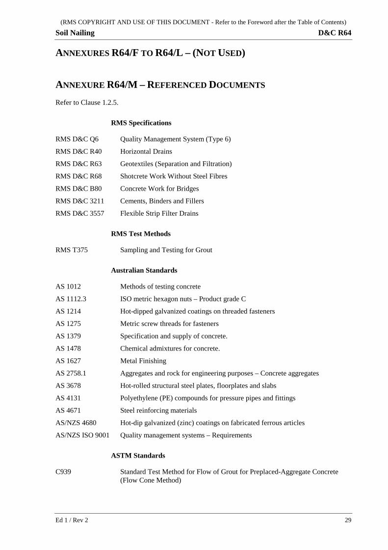
ANNEXURE R64/M – REFERENCED DOCUMENTS Refer to Clause 1.2.5.
RMS Specifications
RMS D&C Q6 Quality Management System (Type 6)
RMS D&C R40 Horizontal Drains
RMS D&C R63 Geotextiles (Separation and Filtration)
RMS D&C R68 Shotcrete Work Without Steel Fibres
RMS D&C B80 Concrete Work for Bridges
RMS D&C 3211 Cements, Binders and Fillers
RMS D&C 3557 Flexible Strip Filter Drains
RMS Test Methods
RMS T375 Sampling and Testing for Grout
Australian Standards
AS 1012 Methods of testing concrete
AS 1112.3 ISO metric hexagon nuts – Product grade C
AS 1214 Hot-dipped galvanized coatings on threaded fasteners
AS 1275 Metric screw threads for fasteners
AS 1379 Specification and supply of concrete.
AS 1478 Chemical admixtures for concrete.
AS 1627 Metal Finishing
AS 2758.1 Aggregates and rock for engineering purposes – Concrete aggregates
AS 3678 Hot-rolled structural steel plates, floorplates and slabs
AS 4131 Polyethylene (PE) compounds for pressure pipes and fittings
AS 4671 Steel reinforcing materials
AS/NZS 4680 Hot-dip galvanized (zinc) coatings on fabricated ferrous articles
AS/NZS ISO 9001 Quality management systems – Requirements
ASTM Standards
C939 Standard Test Method for Flow of Grout for Preplaced-Aggregate Concrete (Flow Cone Method)
Ed 1 / Rev 2 29
(RMS COPYRIGHT AND USE OF THIS DOCUMENT - Refer to the Foreword after the Table of Contents)
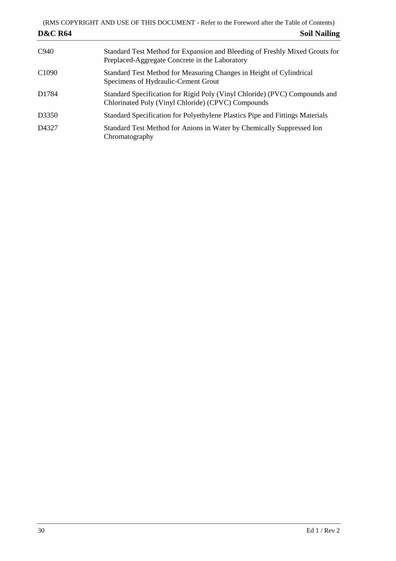
D&C R64 Soil Nailing
C940 Standard Test Method for Expansion and Bleeding of Freshly Mixed Grouts for Preplaced-Aggregate Concrete in the Laboratory
C1090 Standard Test Method for Measuring Changes in Height of Cylindrical Specimens of Hydraulic-Cement Grout
D1784 Standard Specification for Rigid Poly (Vinyl Chloride) (PVC) Compounds and Chlorinated Poly (Vinyl Chloride) (CPVC) Compounds
D3350 Standard Specification for Polyethylene Plastics Pipe and Fittings Materials
D4327 Standard Test Method for Anions in Water by Chemically Suppressed Ion Chromatography
30 Ed 1 / Rev 2