david m. campbell p.c. ny office ny 10901, suffern tensinet... · useful to the designer in...
TRANSCRIPT
TensiNet Symposium 2003I 268 I
Snow Induced Ponding of Textile Membrane Roof Structures
Abstract. Tensioned membrane structures are
unique in their capability to carry very high loads in
relation to their self weight.
This is due in part to the large deflection behaviour
of these structures that renders them relatively
insensitive to specific load distributions. This same
characteristic causes tensioned membrane roof
structures to be uniquely vulnerable to ponding,
typically snow induced.
This paper discusses the issue of snow loads on ten-
sioned membrane structures as well as the poten-
tial for ponding. Ponding of example structures is
reviewed. Design approaches to predict and deal
with snow induced ponding are discussed.
This paper is limited to roof structures employing
textile membranes, as the vast majority of ten-
sioned membrane roof employ textiles; however the
issues and design approaches can be readily applied
to other tension membrane materials, such as films,
foils and metals.
David M. Campbell
Geiger Engineers
P.C. NY Office
2 Executive Blvd., Suite 410
NY 10901, Suffern
USA
Email: [email protected]
www.geigerengineers.com
Designing Tensile Architecture I 269 I
1 SNOW LOADS
Tensioned membrane roof structures have enjoyed significant success in a wide variety ofclimates around the world. There are numerous structures that have been built in climatesthat require the structure to resist significant snow loads. Exempting pneumatic struc-tures, which have their own particular vulnerabilities, most of these structures have goodservice histories with little or no winter difficulties. However, there are a number of roofstructures which have had problems with ponding. These include the Chene ParkAmphitheater canopy in Detroit, MI; the Montage Arts Center Amphitheater in Scranton,PA; the roof of the Georgia Dome in Atlanta, Georgia; and the current roof of the OlympicStadium in Montreal, Quebec. With the exception of the Georgia Dome roof, ponding ofthese roofs has been induced by snow. Ponding instability caused by rain can be quantitatively addressed in non-linear analysis.Assuming some initial load, the deformed roof surface can be assessed for the potentialto retain water. If the deformed surface retains water, a new load can be calculated basedupon the volume of water retained and the structure can be reanalyzed. This cycle can berepeated to ascertain whether the system displays sufficient stiffness to prevent overload.In practice this is rarely necessary, for if a portion of a tensile membrane roof surface isfound not to drain under small gravity loads, it is probable that it will pond. Generally, thestiffness of the membrane structure will be found to increase with deformation, but usu-ally at an inadequate rate to prevent overload when a source of water is present. In suchinstances, the structures shape (form and prestress) will typically require modification. Prediction of snow induced ponding is much more difficult and generally can only beaddressed qualitatively by review and evaluation of both the deformed roof surfaces andthe potential accumulation for snow and water loads in the susceptible areas. An analyti-cal procedure has been used for the special case of air-supported roof membrane panels.(Liddell) A similar approach could be employed to evaluate a particular aspect of a struc-ture, but this would not be particularly useful in the context of design. The difficulty of design with respect to this issue begins with prediction of snow load dis-tributions for tensile membrane structures. Building codes provide definition of over-alldesign snow loads for roof structures. The model codes in currently use in North America,the International Building Code, ASCE 7 and the National Building Code of Canada providegood definition of drift loads and sliding snow surcharges for a variety of roof geometries.However, as with definition of pressure coefficients for roof wind loads, these do not apply to the unique shapes and forms of tensioned membrane structures. Many of thesetensile forms create unique drifting patterns and, because of the surface characteristics ofalmost all structural membrane textile materials, a potential for consolidation of snowloads from sliding.
D. Campbell
TensiNet Symposium 2003I 270 I
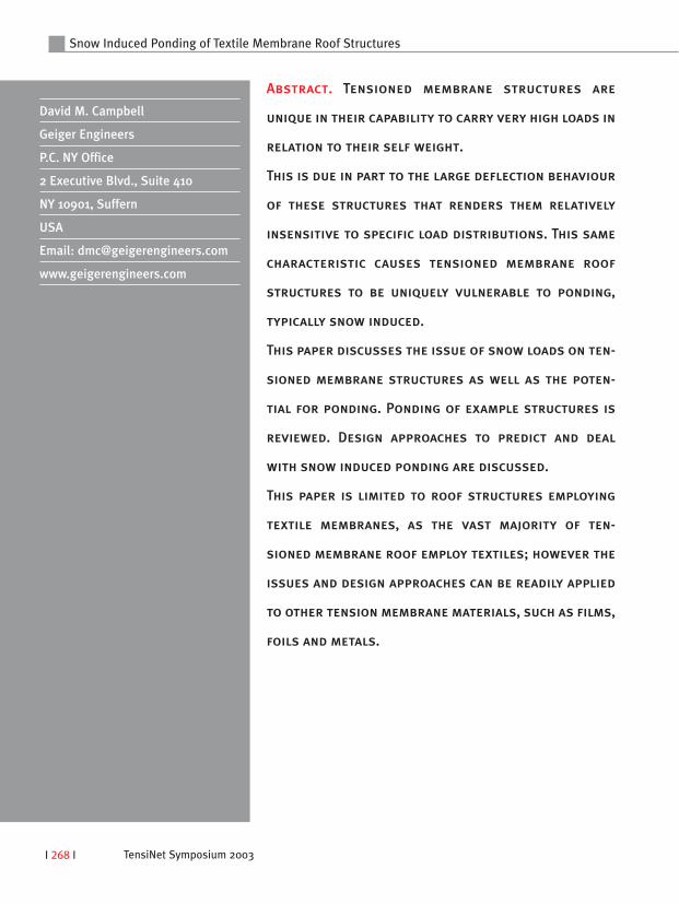
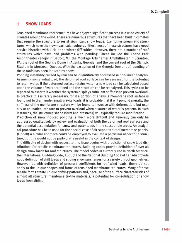
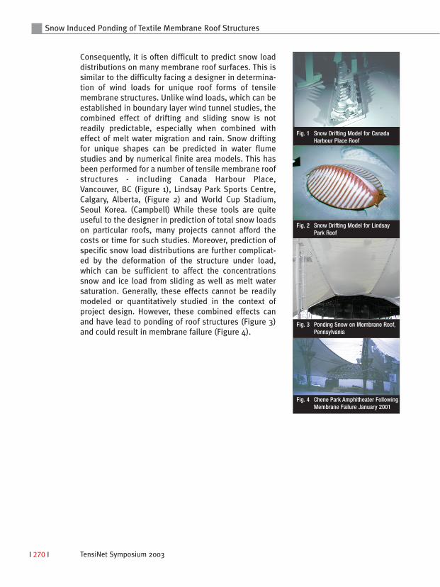
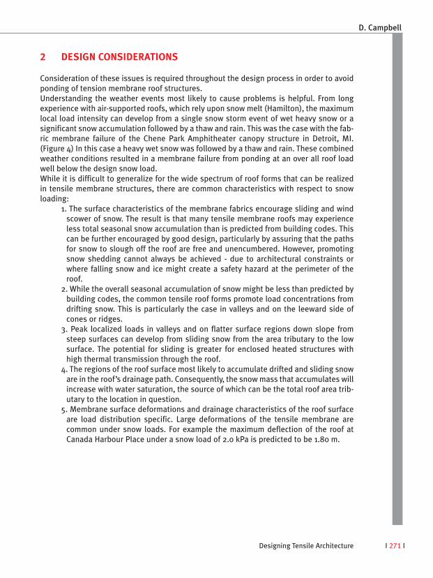
Consequently, it is often difficult to predict snow loaddistributions on many membrane roof surfaces. This issimilar to the difficulty facing a designer in determina-tion of wind loads for unique roof forms of tensilemembrane structures. Unlike wind loads, which can beestablished in boundary layer wind tunnel studies, thecombined effect of drifting and sliding snow is notreadily predictable, especially when combined witheffect of melt water migration and rain. Snow driftingfor unique shapes can be predicted in water flumestudies and by numerical finite area models. This hasbeen performed for a number of tensile membrane roofstructures - including Canada Harbour Place,Vancouver, BC (Figure 1), Lindsay Park Sports Centre,Calgary, Alberta, (Figure 2) and World Cup Stadium,Seoul Korea. (Campbell) While these tools are quiteuseful to the designer in prediction of total snow loadson particular roofs, many projects cannot afford thecosts or time for such studies. Moreover, prediction ofspecific snow load distributions are further complicat-ed by the deformation of the structure under load,which can be sufficient to affect the concentrationssnow and ice load from sliding as well as melt watersaturation. Generally, these effects cannot be readilymodeled or quantitatively studied in the context ofproject design. However, these combined effects canand have lead to ponding of roof structures (Figure 3)and could result in membrane failure (Figure 4).
Snow Induced Ponding of Textile Membrane Roof Structures
Fig. 1 Snow Drifting Model for CanadaHarbour Place Roof
Fig. 2 Snow Drifting Model for LindsayPark Roof
Fig. 3 Ponding Snow on Membrane Roof,Pennsylvania
Fig. 4 Chene Park Amphitheater FollowingMembrane Failure January 2001
Designing Tensile Architecture I 271 I
2 DESIGN CONSIDERATIONS
Consideration of these issues is required throughout the design process in order to avoidponding of tension membrane roof structures. Understanding the weather events most likely to cause problems is helpful. From longexperience with air-supported roofs, which rely upon snow melt (Hamilton), the maximumlocal load intensity can develop from a single snow storm event of wet heavy snow or asignificant snow accumulation followed by a thaw and rain. This was the case with the fab-ric membrane failure of the Chene Park Amphitheater canopy structure in Detroit, MI.(Figure 4) In this case a heavy wet snow was followed by a thaw and rain. These combinedweather conditions resulted in a membrane failure from ponding at an over all roof loadwell below the design snow load. While it is difficult to generalize for the wide spectrum of roof forms that can be realizedin tensile membrane structures, there are common characteristics with respect to snowloading:
1. The surface characteristics of the membrane fabrics encourage sliding and windscower of snow. The result is that many tensile membrane roofs may experienceless total seasonal snow accumulation than is predicted from building codes. Thiscan be further encouraged by good design, particularly by assuring that the pathsfor snow to slough off the roof are free and unencumbered. However, promotingsnow shedding cannot always be achieved - due to architectural constraints orwhere falling snow and ice might create a safety hazard at the perimeter of theroof.
2. While the overall seasonal accumulation of snow might be less than predicted bybuilding codes, the common tensile roof forms promote load concentrations fromdrifting snow. This is particularly the case in valleys and on the leeward side ofcones or ridges.
3. Peak localized loads in valleys and on flatter surface regions down slope fromsteep surfaces can develop from sliding snow from the area tributary to the lowsurface. The potential for sliding is greater for enclosed heated structures withhigh thermal transmission through the roof.
4. The regions of the roof surface most likely to accumulate drifted and sliding snoware in the roof’s drainage path. Consequently, the snow mass that accumulates willincrease with water saturation, the source of which can be the total roof area trib-utary to the location in question.
5. Membrane surface deformations and drainage characteristics of the roof surfaceare load distribution specific. Large deformations of the tensile membrane arecommon under snow loads. For example the maximum deflection of the roof atCanada Harbour Place under a snow load of 2.0 kPa is predicted to be 1.80 m.
D. Campbell
TensiNet Symposium 2003I 272 I
Snow Induced Ponding of Textile Membrane Roof Structures
These loading issues require careful consideration in evaluation of roof forms. Particularmembrane structures features have increased potential for ponding and should be exam-ined:
1. Roof surfaces which have low slopes or flat regions that are in the drainage pathshould be suspect and subject to investigation. Large membrane spans with largeradii of curvature are potential sites ponding instability and should be reviewed.While the presence of snow load can initiate a ponding situation, otherwise freedraining roof structures with very flat large curvature regions have been subject toponding. An example is the Georgia Dome roof in Atlanta, Georgia which lost fourperimeter PTFE coated fiber glass roof panels to ponding during a severe rainstorm. (BD&C) Evaluation of the deformed roof form under live load and, if neces-sary, design adjustments to the shape can prevent these problems. Review of ele-vation contours of the deformed roof form to demonstrate that it is free draining isoften sufficient to evaluate the surface. (Campbell) In the event that the deformedsurface is not found to be free draining, the membrane shape (form and prestress)can be modified by: revising the structural geometry, increasing the stiffness byintroduction of cables at the membrane surface or increasing the membrane pre-stress. In special cases the membrane shape can be established under load andthe “prestress” form determined by unloading the loaded shape. Any or all ofthese in combination can be used to address the problem. The presence of snowadds to the uncertainty of what to consider for local load distribution and peakload intensity in this process.
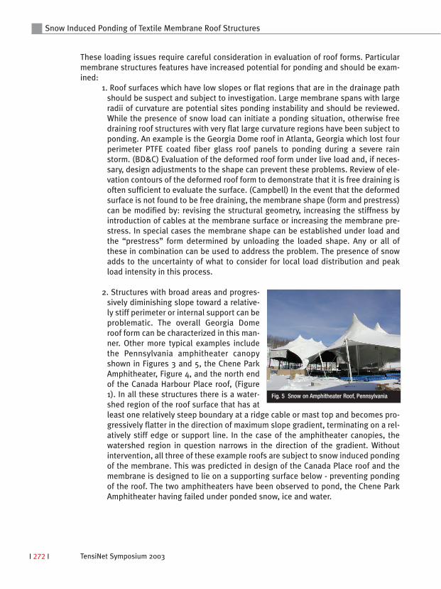
2. Structures with broad areas and progres-sively diminishing slope toward a relative-ly stiff perimeter or internal support can beproblematic. The overall Georgia Domeroof form can be characterized in this man-ner. Other more typical examples includethe Pennsylvania amphitheater canopyshown in Figures 3 and 5, the Chene ParkAmphitheater, Figure 4, and the north endof the Canada Harbour Place roof, (Figure1). In all these structures there is a water-shed region of the roof surface that has atleast one relatively steep boundary at a ridge cable or mast top and becomes pro-gressively flatter in the direction of maximum slope gradient, terminating on a rel-atively stiff edge or support line. In the case of the amphitheater canopies, thewatershed region in question narrows in the direction of the gradient. Withoutintervention, all three of these example roofs are subject to snow induced pondingof the membrane. This was predicted in design of the Canada Place roof and themembrane is designed to lie on a supporting surface below - preventing pondingof the roof. The two amphitheaters have been observed to pond, the Chene ParkAmphitheater having failed under ponded snow, ice and water.
Fig. 5 Snow on Amphitheater Roof, Pennsylvania
Designing Tensile Architecture I 273 I
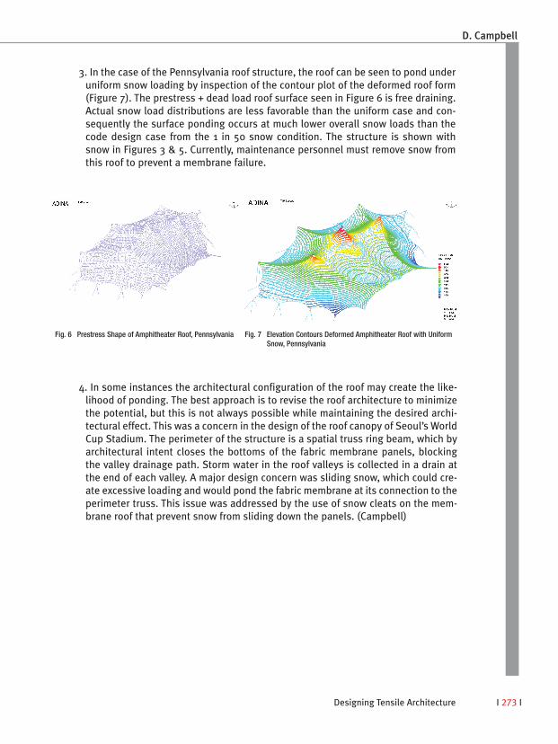
3. In the case of the Pennsylvania roof structure, the roof can be seen to pond underuniform snow loading by inspection of the contour plot of the deformed roof form(Figure 7). The prestress + dead load roof surface seen in Figure 6 is free draining.Actual snow load distributions are less favorable than the uniform case and con-sequently the surface ponding occurs at much lower overall snow loads than thecode design case from the 1 in 50 snow condition. The structure is shown withsnow in Figures 3 & 5. Currently, maintenance personnel must remove snow fromthis roof to prevent a membrane failure.
D. Campbell
Fig. 6 Prestress Shape of Amphitheater Roof, Pennsylvania Fig. 7 Elevation Contours Deformed Amphitheater Roof with UniformSnow, Pennsylvania
4. In some instances the architectural configuration of the roof may create the like-lihood of ponding. The best approach is to revise the roof architecture to minimizethe potential, but this is not always possible while maintaining the desired archi-tectural effect. This was a concern in the design of the roof canopy of Seoul’s WorldCup Stadium. The perimeter of the structure is a spatial truss ring beam, which byarchitectural intent closes the bottoms of the fabric membrane panels, blockingthe valley drainage path. Storm water in the roof valleys is collected in a drain atthe end of each valley. A major design concern was sliding snow, which could cre-ate excessive loading and would pond the fabric membrane at its connection to theperimeter truss. This issue was addressed by the use of snow cleats on the mem-brane roof that prevent snow from sliding down the panels. (Campbell)
TensiNet Symposium 2003I 274 I
Snow Induced Ponding of Textile Membrane Roof Structures
RECOMMENDATIONS
Tensile membrane roofs for application in climates that include snow should be conceivedwith resistance to snow inducing ponding in mind. Where the design requires regions ofthe roof surface that may be subject to snow induced ponding, evaluation of the deformedroof surface under a number of potential snow load distributions should be performed.The loads should consider the water equivalent tributary to the location in question andthe drainage paths. Note that none of this discussion involves fabric membrane stressevaluation. Quantitative stress evaluation is a distinct and separate issue. Ponding willoften lead to failure even when the fabric stresses are well within the permissible rangefor the load condition under evaluation. Evaluation of the deformed surface for drainage isessential. This should be done as part of the evaluation of a shape in the design process.(Campbell) Plotting elevation contours of the roof deformed surface is a simple means toassess whether the surface drains. It may be appropriate to consider greater loads thanare used to evaluate the strength of the membrane in evaluation of drainage. This engi-neering philosophy considers that the formation of a non-draining pond in the membraneis a failure mechanism and thus should be considered as a limit state.
REFERENCES
[1] Liddell, I. “Minnesota Metrodome. A Study on the Behaviour of Air Supported Roofs Under Environmental Loads”, Structural Engineering Review Vol. 6, No. 3-4, pp. 215-235 1994.
[2] Campbell, D., Gossen, P., Chen, D., Shan, W., “Seoul 2002 World Cup Stadium Canopy Roof Structure” Proceedings, Sixth Asian Pacific Conference on Shell andSpatial Structures, Vol. II, pp 1025-1032, October 2000, published by Hakmun Publishing Inc.
[3] Hamilton, K., Campbell, D. and Gossen, P., "Current State of Development and Future Trends in Employment of Air-Supported Roofs in Long-Span Applications", Spatial, Lattice and Tension Structures, IASS-ASCE International Symposium '94, published by the ASCE.
[4] BD&C, “Roof Panels Fail at Georgia Dome” Building Design & Construction, October 1995.
[5] Campbell, D., Chen, D., Gossen, P., and Hamilton, K., “Tensioned Fabric Membrane Roofs for “Tensegrity” Domes”, Proceedings, ASCE Structures Congress XIII '95, Boston MA, published by the ASCE.
[6] Campbell, D., “The Unique Role of Computing in the Design and Construction of Tensile Membrane Structures”, Proceedings, American Society of Civil Engineers Second Civil Engineering Automation Conference, New York, NY, 1991