datenblatt der produkte: atx upsu 8-28v atx upsu 12v atx...
TRANSCRIPT

®
Datasheet of products:ATX UPSU 8-28VATX UPSU 12VATX UPSU CAP EXTENSION KITATX UPSU BATTERY PACKATX UPSU AC
V3.0
Observe safety instructions on page 4 Beachten Sie die Sicherheitsvorschriften auf Seite 4
Datenblatt der Produkte:ATX UPSU 8-28VATX UPSU 12VATX UPSU CAP EXTENSION KITATX UPSU BATTERY PACKATX UPSU AC
English Deutsch
ATX UPSU 8-28V / ATX UPSU 12V ATX UPSU AC
ATX UPSU BATTERY PACK
ATX UPSU CAP EXTEN-SION KIT
ATX UPSU features ATX UPSU Funktionen ► Shuts down even with power supply failure.
Maintenance-free! ► UPS with supercaps ► Possibility to use a standard mainboard and
standard software in industrial, automation and other systems. A database can now be operated in these systems
► Maintenance-free ► 3.5“ small form factor UPS or in standard ATX
Case (ATX UPSU AC) ► Direct output for ATX powered mainboards and
drives ► 12V DC, 8-28V DC and AC input variant available ► Increased capacity possible with ATX UPSU CAP
EXTENSION KIT or ATX UPSU BATTERY PACK ► Automatically controlled shutdown over main-
board power button signal ► Automatic capacitor charge power regulation ► ATX UPSU IPC available ► Mounting accessories available for direct moun-
ting in a computer system on 3.5“ drive
2
► Fährt das laufende Betriebssystem herunter, wenn die Stromversorgung ausgefallen ist. Wartungsfrei!
► USV mit Ultra-/Supercaps ► Ermöglicht die Benutzung eines normalen Main-
boards und normaler Software in Industrie-, Automations- und anderen Systemen. Sogar eine Datenbank kann nun betrieben werden in diesen Systemen.
► Wartungsfreies USV im 3.5“ oder standard ATX- Netzteil (ATX UPSU AC) Formfaktor
► Direkter Anschluss für ATX Mainboards und Laufwerke
► 12V DC, 8-28V DC und AC Spannungseingang Variante erhältlich
► Kapazitättserweiterung mit ATX UPSU CAP EXTENSION KIT oder ATX UPSU BATTERY PACK
► Automatisches herunterfahren über den Main- board Power Button Signal
► Automatische Ladeleistungsregelung der Kon- densatoren
► ATX UPSU IPC erhältlich ► Montagezubehör erhältlich für die direkte Monta-
ge in ein Computersystem auf 3.5“ Laufwerk
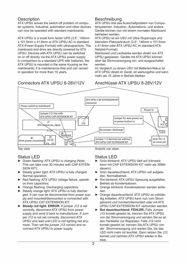
Typical application Typische Anwendung
Power source
ATX MainboardATX power
Power btn
Power buttonor jumper HDD / SSD / CD Specific hardwareIDE / SATA
ATX UPSU
Applications ► Industrial computers (IPC) ► Embedded servers ► Slot machines and vending machines ► Car PCs ► Automation systems ► ...
► Industrie Computers (IPC) ► Embedded Server ► Getränke- und Spielautomaten ► CAR PCs ► Automationssysteme ► ...
Einsatzgebiete
Notes to ATX UPSU types Hinweis zu den ATX UPSU TypenIf not otherwise described, all informations refers to ATX UPSU 12V, ATX UPSU 8-28V and ATX UPSU AC.ATX UPSU 8-28V/12V means, that the informations only refers to ATX UPSU 8-28V and ATX UPSU 12V.ATX UPSU AC means, that informations only refers to ATX UPSU AC.
Wenn nicht anders beschrieben, gelten die Infor-mationen in diesem Datenblatten für die Typen ATX UPSU 12V, ATX UPSU 8-28V und ATX UPSU AC.ATX UPSU 8-28V/12V bedeutet, dass Informationen für ATX UPSU 8-28V und ATX UPSU 12V gelten.ATX UPSU AC bedeutet, dass Informationen nur für ATX UPSU AC gelten.
3
Description BeschreibungATX UPSU löst das Ausschaltproblem von Compu-tersystemen. Industrie-, Automations- und andere Geräte können nun mit einem normalen Mainboard betrieben werden.ATX UPSU ist ein USV mit Ultra-/Supercaps und kleinstem Platzverbrauch (3.5“, 146mm x 101.6mm x 41.6mm oder ATX UPSU AC im standard ATX-Netzteil-Format).Mainboard und Laufwerke werden direkt von ATX UPSU gespiesen. Geräte mit ATX UPSU können über die Stromversorgung ein- und ausgeschaltet werden.Im Vergleich zu einem USV mit Batterien/Akkus ist ATX UPSU direkt im Gerät, ist wartungsfrei und kann mehr als 10 Jahre in Betrieb bleiben.
ATX UPSU solves the switch-off problem of compu-ter systems. Industrial, automation and other devices can now be operated with standard mainboards.
ATX UPSU is a small form factor UPS (3.5“, 146mm x 101.6mm x 41.6mm or ATX UPSU AC in standard ATX-Power-Supply-Format) with ultracapacitors. The mainboard and drive are directly powered by ATX UPSU. Devices with ATX UPSU can be switched on or off directly via the ATX UPSU power supply. In comparison to a standard UPS with batteries, the ATX UPSU is mounted in the same housing as the mainboards; it is maintenance-free and can remain in operation for more than 10 years.
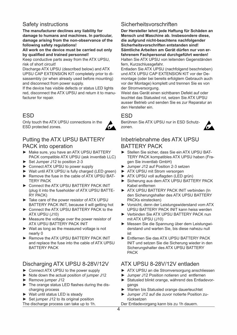
Connectors ATX UPSU 8-28V/12V Anschlüsse ATX UPSU 8-28V/12V
ATX connector, 24pin
Drive power connector
Reserved
5V DC
ATX UPSU CAP EXTENSION KIT connector
Power switch to mainboard
No jumper: discharge
Jumper for auto power onor power button in
Power in
VCC
Jack: VCC ison inner pin
Jumper 1-2: Normal use withoutATX UPSU CAP EXTENSION KIT
Jumper 2-3: Use withATX UPSU CAP EXTENSION KIT
J12J2
J3
J8
J7 J10
J9
J6
J5
J4
Top view Ansicht von oben
► Grün blinkend: ATX UPSU lädt auf (Hinweis: kann mit CAP EXTENSION KIT mehr als 30Min dauern).
► Grün dauerleuchtend: ATX UPSU voll aufgela- den, Normalbetrieb.
► Rot blinkend: ATX UPSU Speisung ausgefallen, Betrieb ab Kondensatoren.
► Orange blinkend: Kondensatoren werden entla- den.
► Orange dauerleuchtend: ATX UPSU ist vollstän- dig entladen. ATX UPSU kann nun vom Strom getrennt und montiert/demontiert oder mit ATX UPSU CAP EXTENSION KIT verbunden werden.
► Rot dauerleuchtend: FEHLER. Falls Jumper J12 korrekt gesetzt ist, trennen Sie ATX UPSU von der Stromversorgung und senden Sie es an den Hersteller zur Reparatur. Falls J12 nicht korrekt gesetzt ist, trennen Sie ATX UPSU von der Stromversorgung und warten Sie, bis das LED nicht mehr rot leuchtet. Dann setzen Sie J12 korrekt und nehmen ATX UPSU wieder in Be- trieb.
Status LED ► Green flashing: ATX UPSU is charging (Note:
This can take over 30 minutes with CAP EXTEN- SION KIT).
► Steady green light: ATX UPSU is fully charged. Normal operation.
► Red flashing: ATX UPSU voltage failure, operati- on from capacitors.
► Orange flashing: Discharging capacitors. ► Steady orange light: ATX UPSU is fully dischar-
ged. It can now be disconnected from power sup- ply and mounted/dismounted or connected with ATX UPSU CAT EXTENSION KIT.
► Steady red light: ERROR. If jumper J12 is set correctly, disconnect ATX UPSU from power supply and send it back to manufacturer. If Jum- per J12 is not set correctly, disconnect ATX UPSU and wait until LED is not lighting red any- more. Then set the jumper J12 correct and re- connect ATX UPSU to power supply.
Status LED
4
SicherheitsvorschriftenSafety instructionsDer Hersteller lehnt jede Haftung für Schäden an Mensch und Maschine ab. Insbesondere diese, die aufgrund nicht-beachtens nachfolgender Sicherheitsvorschriften entstanden sind!Sämtliche Arbeiten am Gerät dürfen nur von er-fahrenem Fachpersonal durchgeführt werden!Halten Sie ATX UPSU von leitenden Gegenständen fern, Kurzschlussgefahr.Entladen Sie ATX UPSU (nachfolgend beschrieben) und ATX UPSU CAP EXTENSION KIT vor der De-montage (oder bei bereits erfolgtem Gebrauch auch vor der Montage) komplett und trennen Sie es von der Stromversorgung.Weist das Gerät einen sichtbaren Defekt auf oder leuchtet das Statusled rot, setzen Sie ATX UPSU ausser Betrieb und senden Sie es zur Reparatur an den Hersteller ein.
ESDBerühren Sie ATX UPSU nur in ESD Schutz-zonen.
The manufacturer declines any liability for damage to humans and machines. In particular, damage arising from the non-observance of the following safety regulations!All work on the device must be carried out only by qualified and trained personnel!Keep conductive parts away from the ATX UPSU, risk of short circuit!Discharge ATX UPSU (described below) and ATX UPSU CAP EXTENSION KIT completely prior to di-sassembly (or when already used before mounting) and disconnect from power supply.If the device has visible defects or status LED lights red, disconnect the ATX UPSU and return it to manu-facturer for repair.
ESDOnly touch the ATX UPSU connections in the ESD protected zones.
Inbetriebnahme des ATX UPSUBATTERY PACK
► Stellen Sie sicher, dass Sie ein ATX UPSU BAT- TERY PACK kompatibles ATX UPSU haben (Fra- gen Sie inventlab GmbH)
► Jumper J12 auf Position 2-3 setzen ► ATX UPSU mit Strom versorgen ► ATX UPSU voll auflagden (LED grün) ► Sicherung aus dem ATX UPSU BATTERY PACK
Kabel entfernen ► ATX UPSU BATTERY PACK INIT verbinden (In
den Sicherungshalter des ATX UPSU BATTERY PACKs einstecken)
► Vorsicht, denn der Leistungswiderstand vom ATX UPSU BATTERY PACK INIT kann heiss werden
► Verbinden Sie ATX UPSU BATTERY PACK nun mit ATX UPSU (J10)
► Messen Sie die Spannung über dem Leistungwi- derstand und warten Sie, bis diese nahezu null ist
► Entfernen Sie das ATX UPSU BATTERY PACK INIT und setzen Sie die Sicherung wieder in den Sicherungshalter des ATX UPSU BATTERY PACK
Putting the ATX UPSU BATTERY PACK into operation
► Make sure, you have an ATX UPSU BATTERY PACK compatible ATX UPSU (ask inventlab LLC)
► Set Jumper J12 to position 2-3 ► Connect ATX UPSU to power supply ► Wait until ATX UPSU is fully charged (LED green) ► Remove the fuse in the cable of ATX UPSU BAT-
TERY PACK ► Connect the ATX UPSU BATTERY PACK INIT
(plug it into the fuseholder of ATX UPSU BATTE- RY PACK)
► Take care of the power resistor of ATX UPSU BATTERY PACK INIT, because it will getting hot
► Connect the ATX UPSU BATTERY PACK to the ATX UPSU (J10)
► Measure the voltage over the power resistor of ATX UPSU BATTERY PACK INIT
► Wait as long as the measured voltage is not nearly 0
► Remove the ATX UPSU BATTERY PACK INIT and replace the fuse into the cable of ATX UPSU BATTERY PACK
ATX UPSU 8-28V/12V entladen ► ATX UPSU an die Stromversorgung anschliessen ► Jumper J12 Position notieren und entfernen ► Statusled blinkt orange, während des Entladevor-
gangs ► Warten bis Statusled orange dauerleuchtet ► Jumper J12 auf die zuvor notierte Position zu -
rücksetzenDer Entladevorgang kann bis zu 1h dauern.
Discharging ATX UPSU 8-28V/12V ► Connect ATX UPSU to the power supply ► Note down the actual position of jumper J12 ► Remove jumper J12 ► The orange status LED flashes during the dis -
charging process ► Wait until status LED is steady ► Set jumper J12 to its original position
The discharge process can take up to 1h.

5
ATX UPSU 8-28V/12VInbetreibnahme
ATX UPSU 8-28V/12Voperating instructions
► Mainboard mit ATX UPSU über den 24 Pol ATX Anschluss J7 verbinden
► Laufwerk/e mit J8 verbinden. ► Mainboard Power Switch/Button mit J2 verbinden
(auf Polung achten) ► An J3 den Power Button anschliessen, wenn das
System nicht automatisch eingeschaltet werden soll. Wenn auf J3 ein Jumper gesetzt ist, schal- tet ATX UPSU das Mainboard nach Anschluss der Stromversorgung automatisch ein.
► ATX UPSU über den Spannungseingang J6 (Ter- minal Block) oder J7 (Jack) speisen
► ATX UPSU 12V muss an einer konstanten 12V DC Spannungsquelle angeschlossen werden, wobei ATX UPSU 8-28V für den Spannungsbe- reich von 8 bis 28V DC geeignet ist.
► Am Spannungseingang ist es empfehlenswert, eine Supressordiode zu verwenden, falls ATX UPSU an einer Spannungsquelle mit möglichen Überspannungsspitzen betreiben wird (z.B. in einem Fahrzeug).
► J9 ist ein 5V Spannungsausgang. Wenn an J9 ein Relais angeschlossen wird, muss zusätzlich eine Freilaufdiode eingebaut werden. Hinweis: J9 teilt den Strom mit ATX und den Laufwerken. Seien Sie vorsichtig und nutzen Sie gesamthaft nicht mehr Strom als in den Absolute Maximum Ratings angegeben.
ATX UPSU 8-28V/12V hat keine Sicherung und kein Verpolungsschutz am Spannungseingang. Eine Ver-polung oder ein Kurzschluss kann das Gerät irrepa-rabel zerstören.ATX UPSU CAP EXTENSION KIT und das ATX UPSU BATTERY PACK hat im Kabel eine Siche-rung. Diese Sicherung kann zerstört werden, wenn ATX UPSU vor dem Anschluss des ATX UPSU CAP EXTENSION KITs nicht wie beschrieben entladen wird.
Sicherung, Verpolungsschutz
► Connect mainboard with ATX UPSU via the 24- pin ATX connector J7
► Connect drive/s with J8 ► Connect mainboard power switch/button with J2
(observe correct polarity) ► If the system does not start automatically, con-
nect the power button to J3. If a jumper is set to J3, the ATX UPSU automatically switches on the mainboard when power supply is connected.
► Feed the ATX UPSU via voltage input J6 (termi- nal block) or J7 (jack)
► ATX UPSU 12V must be connected to a cons- tant 12V DC power source, whereby the ATX UPSU 8-28V is suitable for the voltage range from 8 up to 28V.
► It is recommended to use a suppressor diode on voltage input, if the ATX UPSU is operated via a power source with potentially high voltage peaks (e.g. in a vehicle).
► J9 is a 5V DC voltage output. If a relay is con nected to J9, a free-wheeling diode must be ins- talled additionally. Note: J9 shares power with the ATX and drives. Take care and do not use any more electricity than that specified in the Absolute Maximum Ratings.
The ATX UPSU 8-28V/12V has no fuse or reverse polarity protection. Reverse polarity or short circuit can irreparably destroy the ATX UPSU.The ATX UPSU CAP EXTENSION KIT and the ATX UPSU BATTERY PACK has a fuse in the cable. This fuse can be destroyed when the ATX UPSU is not discharged as described earlier, prior to the connec-tion of the ATX UPSU CAP EXTENSION KIT.
Fuse, reverse polarity protection
Operating system configurationConfigure the operating system to shut down when the power button is activated.
Betriebssystem KonfigurationKonfigurieren Sie das Betriebssystem so, dass es herunterfährt, wenn der Einschalttaster gedrückt wurde.
Inbetriebnahme des ATX UPSU CAP EXTENSION KIT
► ATX UPSU 8-28V/12V entladen (siehe oben) ► Jumper J12 auf Position 2-3 setzen ► ATX UPSU CAP EXTENSION KIT anschliessen
Putting the ATX UPSU CAP EXTEN-SION KIT into operation
► Discharge ATX UPSU 8-28V/12V (see above) ► Set jumper J12 to position 2-3 ► Connect ATX UPSU CAP EXTENSION KIT
6
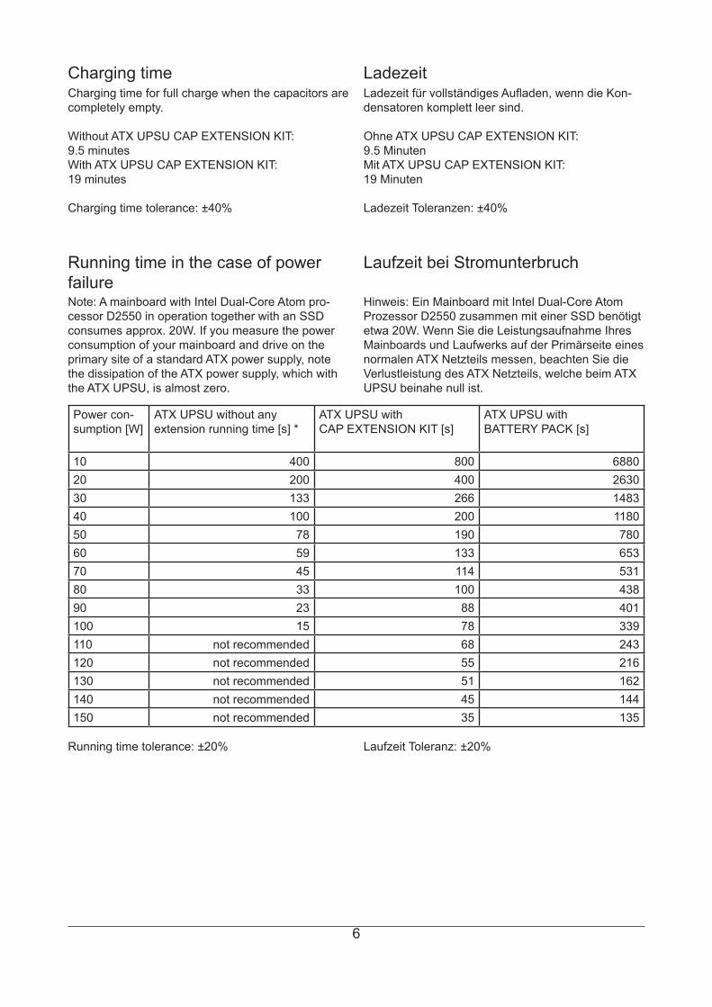
Running time in the case of power failure
Laufzeit bei Stromunterbruch
Power con-sumption [W]
ATX UPSU without any extension running time [s] *
ATX UPSU with CAP EXTENSION KIT [s]
ATX UPSU with BATTERY PACK [s]
10 400 800 688020 200 400 263030 133 266 148340 100 200 118050 78 190 78060 59 133 65370 45 114 53180 33 100 43890 23 88 401100 15 78 339110 not recommended 68 243120 not recommended 55 216130 not recommended 51 162140 not recommended 45 144150 not recommended 35 135
Laufzeit Toleranz: ±20%
Note: A mainboard with Intel Dual-Core Atom pro-cessor D2550 in operation together with an SSD consumes approx. 20W. If you measure the power consumption of your mainboard and drive on the primary site of a standard ATX power supply, note the dissipation of the ATX power supply, which with the ATX UPSU, is almost zero.
Hinweis: Ein Mainboard mit Intel Dual-Core Atom Prozessor D2550 zusammen mit einer SSD benötigt etwa 20W. Wenn Sie die Leistungsaufnahme Ihres Mainboards und Laufwerks auf der Primärseite eines normalen ATX Netzteils messen, beachten Sie die Verlustleistung des ATX Netzteils, welche beim ATX UPSU beinahe null ist.
Ladezeit für vollständiges Aufladen, wenn die Kon-densatoren komplett leer sind.
Ohne ATX UPSU CAP EXTENSION KIT:9.5 Minuten Mit ATX UPSU CAP EXTENSION KIT:19 Minuten
Ladezeit Toleranzen: ±40%
LadezeitCharging time for full charge when the capacitors are completely empty.
Without ATX UPSU CAP EXTENSION KIT:9.5 minutes With ATX UPSU CAP EXTENSION KIT:19 minutes
Charging time tolerance: ±40%
Charging time
Running time tolerance: ±20%
7
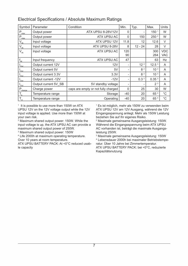
Electrical Specifications / Absolute Maximum RatingsSymbol Parameter Condition Min. Typ. Max. UnitsPmax Output power ATX UPSU 8-28V/12V 0 - 150 1 WPmax Output power ATX UPSU AC 0 150 250 2 WVIN Input voltage ATX UPSU 12V 11.8 12 12.6 VVIN Input voltage ATX UPSU 8-28V 8 12 - 24 28 VVIN Input voltage ATX UPSU AC 120
90300264
VDCVAC
fIN Input frequency ATX UPSU AC 47 63 HzIOut Output current 12V 12V - 12 2 12.5 3 AIOut Output current 5V 5V - 8 2 10 3 AIOut Output current 3.3V 3.3V - 8 2 10 3 AIOut Output current -12V -12V - 0.3 2 0.35 3 AIOut Output current 5V_SB 5V standby voltage - - 2 3 APcharge Charge power caps are empty or not fully charged 0 25 30 WTA Temperature range Storage -40 20 65 4 °CTO Temperature range Operating -40 20 65 4 °C
1 It is possible to use more than 150W on ATX UPSU 12V on the 12V voltage output while the 12V input voltage is applied. Use more than 150W at your own risk.2 Maximum shared output power: 150W. While the input voltage is up, the ATX UPSU AC can provide a maximum shared output power of 250W.3 Maximum shared output power: 150W4 Life 2000h at maximum operating temperature. Over 10 years at room temperature.ATX UPSU BATTERY PACK: At <0°C reduced usab-le capacity
1 Es ist möglich, mehr als 150W zu verwenden beim ATX UPSU 12V am 12V Ausgang, während die 12V Eingangsspannung anliegt. Mehr als 150W Leistung beziehen Sie auf Ihr eigenes Risiko.2 Maximale gemeinsame Ausgangsleistung: 150W. Während die Eingangsspannung beim ATX UPSU AC vorhanden ist, beträgt die maximale Ausgangs-leistung 250W.3 Maximale gemeinsame Ausgangsleistung: 150W4 Lebensdauer 2000h bei maximaler Betriebstempe-ratur. Über 10 Jahre bei Zimmertemperatur.ATX UPSU BATTERY PACK: bei <0°C, reduzierte Kapazitätsnutzung
8
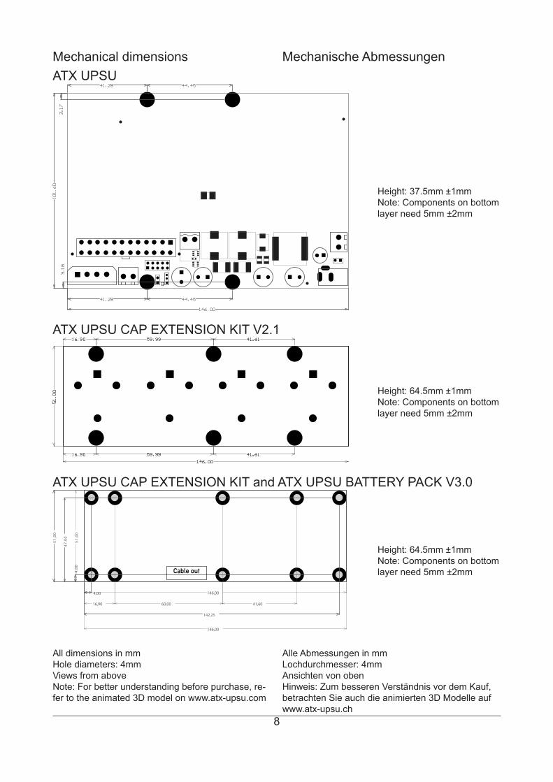
Mechanical dimensions Mechanische AbmessungenATX UPSU
All dimensions in mmHole diameters: 4mmViews from aboveNote: For better understanding before purchase, re-fer to the animated 3D model on www.atx-upsu.com
Alle Abmessungen in mmLochdurchmesser: 4mmAnsichten von obenHinweis: Zum besseren Verständnis vor dem Kauf, betrachten Sie auch die animierten 3D Modelle aufwww.atx-upsu.ch
ATX UPSU CAP EXTENSION KIT V2.1
Height: 37.5mm ±1mmNote: Components on bottom layer need 5mm ±2mm
Height: 64.5mm ±1mmNote: Components on bottom layer need 5mm ±2mm
ATX UPSU CAP EXTENSION KIT and ATX UPSU BATTERY PACK V3.0
Height: 64.5mm ±1mmNote: Components on bottom layer need 5mm ±2mm
16,90
51,00
47,00
4,00
60,00
146,00
142,25
4,00
41,60
51,00
146,00
Cable out
9
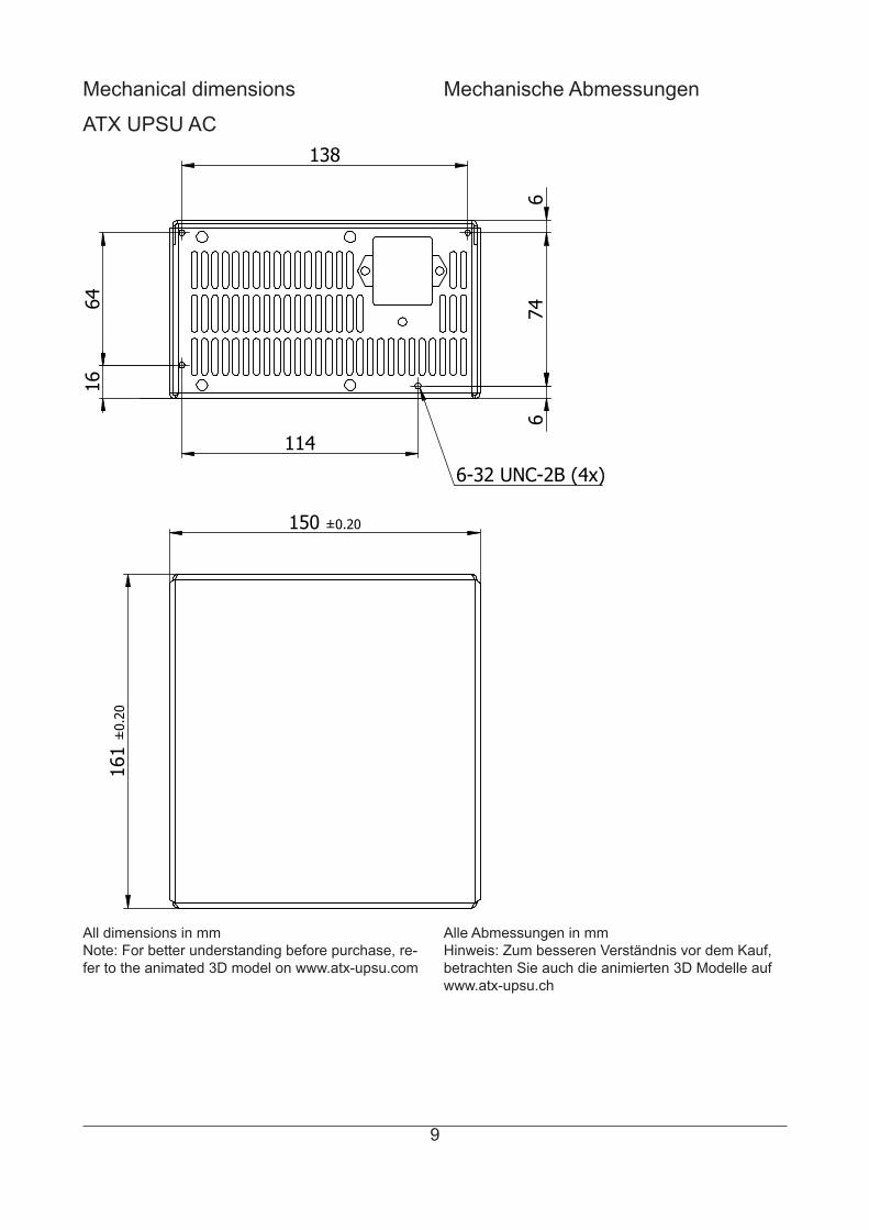
Mechanical dimensions Mechanische Abmessungen
ATX UPSU AC 1
61 ±
0.20
150 ±0.20
138
64
16
114
6
74
6-32 UNC-2B (4x)
6
All dimensions in mmNote: For better understanding before purchase, re-fer to the animated 3D model on www.atx-upsu.com
Alle Abmessungen in mmHinweis: Zum besseren Verständnis vor dem Kauf, betrachten Sie auch die animierten 3D Modelle aufwww.atx-upsu.ch
10
All copies other than the version on atx-upsu.ch/atx-upsu.com website are uncontrolled and may not be up to date. inventlab LLC reserves the right to change the design or construction of any products or limit distri-bution of any products without prior notice. The information in this document is only to be used in connection with inventlab LLC products and is for users to engineer and design their applications with inventlab LLC products.inventlab®, CHYPSOTECH®, ElektronikEntwicklung.ch®, ATX UPSU®, 20W UPSU®, MIL UPSU®, PC104 UPSU®, Das Zuhause der Technik.® and ercotima® are registered trademarks of inventlab LLC, all other brand names, trademarks and registered trademarks are property of their respective owners.
Disclaimer
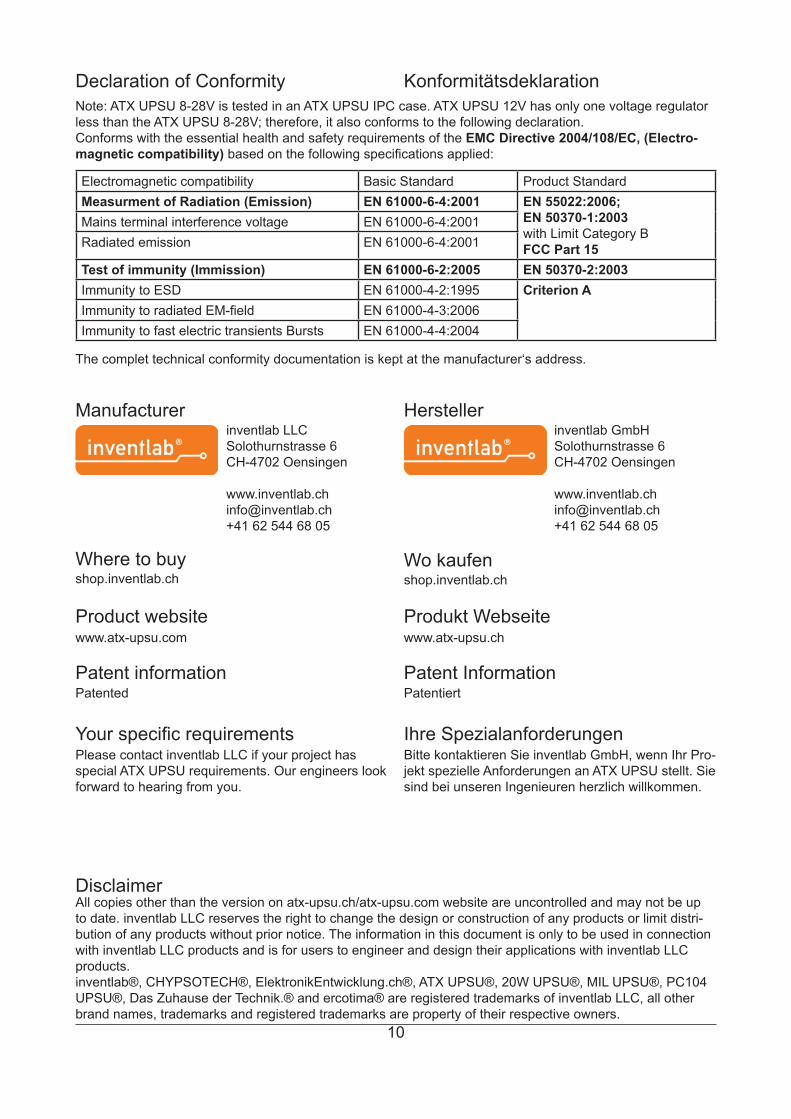
HerstellerManufacturerinventlab LLCSolothurnstrasse 6CH-4702 Oensingen
[email protected]+41 62 544 68 05
Product website Produkt Webseitewww.atx-upsu.com www.atx-upsu.ch
inventlab GmbHSolothurnstrasse 6CH-4702 Oensingen
[email protected]+41 62 544 68 05
Patented PatentiertPatent information Patent Information
Your specific requirements Ihre SpezialanforderungenPlease contact inventlab LLC if your project has special ATX UPSU requirements. Our engineers look forward to hearing from you.
Bitte kontaktieren Sie inventlab GmbH, wenn Ihr Pro-jekt spezielle Anforderungen an ATX UPSU stellt. Sie sind bei unseren Ingenieuren herzlich willkommen.
Declaration of Conformity
The complet technical conformity documentation is kept at the manufacturer‘s address.
Note: ATX UPSU 8-28V is tested in an ATX UPSU IPC case. ATX UPSU 12V has only one voltage regulator less than the ATX UPSU 8-28V; therefore, it also conforms to the following declaration. Conforms with the essential health and safety requirements of the EMC Directive 2004/108/EC, (Electro-magnetic compatibility) based on the following specifications applied:
Electromagnetic compatibility Basic Standard Product StandardMeasurment of Radiation (Emission) EN 61000-6-4:2001 EN 55022:2006;
EN 50370-1:2003with Limit Category BFCC Part 15
Mains terminal interference voltage EN 61000-6-4:2001Radiated emission EN 61000-6-4:2001
Test of immunity (Immission) EN 61000-6-2:2005 EN 50370-2:2003Immunity to ESD EN 61000-4-2:1995 Criterion AImmunity to radiated EM-field EN 61000-4-3:2006Immunity to fast electric transients Bursts EN 61000-4-4:2004
Konformitätsdeklaration
Where to buyshop.inventlab.ch
Wo kaufenshop.inventlab.ch