datasheet - rgbautomatyka.pl · fanuc ac servo motor @+ series fanuc ac spindle motor @+ series...
TRANSCRIPT
RGB ELEKTRONIKA AGACIAK CIACIEKSPÓŁKA JAWNA Jana Dlugosza 2-6 Street51-162 WrocławPoland
[email protected] +48 71 325 15 05
www.rgbautomatyka.pl
www.rgbelektronika.pl
DATASHEET
www.rgbautomatyka.plwww.rgbelektronika.pl
OTHER SYMBOLS:
A860-0304-T112
A8600304T112, A8600304 T112, A8600304-T112, A860 0304T112, A860 0304 T112, A860 0304-T112,A860-0304T112, A860-0304 T112, A860-0304-T112
FANUC

YOUR PARTNER IN MAINTENANCE
At our premises in Wrocław, we have a fully equipped servicing facility. Here we perform all the repair works and test each later sold unit. Our trained employees, equipped with a wide variety of tools and having several testing stands at their disposal, are a guarantee of the highest quality service.
OUR SERVICES
ENCODERS
SERVO DRIVERS
LINEAR ENCODERS
SERVO AMPLIFIERS
CNC MACHINES
MOTORS
POWER SUPPLIERS
OPERATOR PANELS
CNC CONTROLS
INDUSTRIAL COMPUTERS
PLC SYSTEMS
Repair this product with RGB ELEKTRONIKA ORDER A DIAGNOSIS
Buy this product at RGB AUTOMATYKA BUY
FANUC AC SERVO MOTOR @+ seriesFANUC AC SPINDLE MOTOR @+ seriesFANUC SERVO AMPLIFIER @+ series
MAINTENANCE MANUAL
B-65285EN/04

• No part of this manual may be reproduced in any form. • All specifications and designs are subject to change without notice.
The products in this manual are controlled based on Japan’s “Foreign Exchange and Foreign Trade Law”. The export from Japan may be subject to an export license by the government of Japan. Further, re-export to another country may be subject to the license of the government of the country from where the product is re-exported. Furthermore, the product may also be controlled by re-export regulations of the United States government. Should you wish to export or re-export these products, please contact FANUC for advice.
In this manual we have tried as much as possible to describe all the various matters. However, we cannot describe all the matters which must not be done, or which cannot be done, because there are so many possibilities. Therefore, matters which are not especially described as possible in this manual should be regarded as ”impossible”.
• If operation is abnormal, for example, when an alarm is issued or a hardware failure occurs, the operation described in this manual is not guaranteed unless otherwise specifically noted. If operation is abnormal, take action according to the instructions specifically described in this manual if any or contact FANUC when the instructions are not described.
• Generally, a "safety function" means a function that protects the operators from danger posed by the machine. The signals and functions described in this manual cannot be used separately for any "safety function" unless otherwise described as being [usable for the safety function]. Their specifications are not assumed to be used as the [safety function] in this case, unexpected danger may be caused. If you have any questions, contact FANUC.
• A device connection error or setting error can lead to unpredictable operation. When starting to operate the machine for the first time after assembling the machine, replacing parts, or changing parameter settings, exercise extreme care.
B-65285EN/04 SAFETY PRECAUTIONS
s-1
SAFETY PRECAUTIONS The "Safety Precautions" section describes the safety precautions relating to the use of FANUC servo motors, spindle motors, and servo amplifiers (Power Supply, Servo Amplifier, and Spindle Amplifier). Users of any servo motor or amplifier model are requested to read the "Safety Precautions" carefully before using the servo motor or amplifier. The users are also requested to read an applicable specification manual carefully and understand each function of the motor or amplifier for correct use. The users are basically forbidden to do any behavior or action not mentioned in the "Safety Precautions." They are invited to ask FANUC previously about what behavior or action is prohibited.
Contents 1.1 DEFINITION OF WARNING, CAUTION, AND NOTE.................................................................s-2 1.2 FANUC AC SERVO MOTOR αis/αi series
FANUC AC SPINDLE MOTOR αi series ........................................................................................s-3 1.2.1 Warning .....................................................................................................................................s-3 1.2.2 Caution.......................................................................................................................................s-5 1.2.3 Note............................................................................................................................................s-6
1.3 FANUC SERVO AMPLIFIER αi series ...........................................................................................s-8 1.3.1 Warnings and Cautions Relating to Mounting...........................................................................s-8
1.3.1.1 Warning .....................................................................................................................s-8 1.3.1.2 Caution ......................................................................................................................s-9 1.3.1.3 Note .........................................................................................................................s-10
1.3.2 Warnings and Cautions Relating to a Pilot Run ......................................................................s-10 1.3.2.1 Warning ...................................................................................................................s-10 1.3.2.2 Caution ....................................................................................................................s-11
1.3.3 Warnings and Cautions Relating to Maintenance....................................................................s-12 1.3.3.1 Warning ...................................................................................................................s-12 1.3.3.2 Caution ....................................................................................................................s-13 1.3.3.3 Note .........................................................................................................................s-13

SAFETY PRECAUTIONS B-65285EN/04
s-2
1.1 DEFINITION OF WARNING, CAUTION, AND NOTE This manual includes safety precautions for protecting the user and preventing damage to the machine. Precautions are classified into Warning and Caution according to their bearing on safety. Also, supplementary information is described as a Note. Read the Warning, Caution, and Note thoroughly before attempting to use the machine.
WARNING Applied when there is a danger of the user being injured or when there is a
damage of both the user being injured and the equipment being damaged if the approved procedure is not observed.
CAUTION
Applied when there is a danger of the equipment being damaged, if the approved procedure is not observed.
NOTE The Note is used to indicate supplementary information other than Warning and
Caution. If a precaution described even as "CAUTION" is not followed, a serious result may be caused depending on the status. Be sure to follow the precautions described as "WARNING" and "CAUTION" since they give important information. * Read this manual carefully, and store it in a safe place.
B-65285EN/04 SAFETY PRECAUTIONS
s-3
1.2 FANUC AC SERVO MOTOR αis/αi series FANUC AC SPINDLE MOTOR αi series
1.2.1 Warning
WARNING
- Be sure to ground a motor frame. To avoid electric shocks, be sure to connect the grounding terminal in the terminal box to the grounding terminal of the machine.
- Before starting to connect a motor to electric wires, make sure they are isolated from an electric power source.
A failure to observe this caution is vary dangerous because you may get electric shocks.
- Do not ground a motor power wire terminal or short-circuit it to another power wire terminal.
A failure to observe this caution may cause electric shocks or a burned wiring. * Some motors require a special connection such as a winding changeover. For details, refer to Chapter
7, "OUTLINE DRAWINGS," in B-65262EN.
- When connecting a cord such as a power line to the terminal block, use specified tightening torque to firmly connect the cord.
If operation is performed with a loose terminal, the terminal block can overheat, resulting in a fire. Moreover, a terminal can be detached, resulting in a ground fault, short circuit, or electric shock.
- Do not apply current when a terminal of the terminal block or the crimp terminal of a power line is exposed.
If the hand or a conductive object touches a terminal of the terminal block or the crimp terminal of a power line, you may get electric shocks. Attach an insulation cover (accessory) onto the terminal block. Moreover, cover the crimp terminal at the tip of a power line with an insulation tube.
- Assemble and install a power connector securely. If a power line is detached due to a failure in crimping or soldering, or a conductive area is exposed due to a failure in shell assembly, you may get electric shocks.
- Do not touch a motor with a wet hand. A failure to observe this caution is vary dangerous because you may get electric shocks.
- Before touching a motor, shut off the power to it. Even if a motor is not rotating, there may be a voltage across the terminals of the motor. Especially before touching a power supply connection, take sufficient precautions. Otherwise you may get electric shocks.
- Do not touch any terminal of a motor for a while (at least 20 minutes) after the power to the motor is shut off.
High voltage remains across power line terminals of a motor for a while after the power to the motor is shut off. So, do not touch any terminal or connect it to any other equipment. Otherwise, you may get electric shocks or the motor and/or equipment may get damaged.
- On the machine, install a stop device for securing safety. The brake built into the servo motor is not a stop device for securing safety. The machine may not be held if a failure occurs.
SAFETY PRECAUTIONS B-65285EN/04
s-4
WARNING
- Do not enter the area under the vertical axis without securing safety.
If a vertical axis drop occurs unexpectedly, you may be injured.
- Fasten a motor firmly before driving the motor. If a motor is driven when the motor is not fastened firmly or is fastened insufficiently, the motor can tumble or is removed, resulting in a danger. If the motor mounting section is not sufficiently strong, the machine may be damaged or the user may be injured.
- Do not get close to a rotary section of a motor when it is rotating. When a motor is rotating, clothes or fingers can be caught, resulting in an injury.
- Do not drive a motor with an object such as a key exposed. An object such as a key can be thrown away, resulting in an injury. Before rotating a motor, check that there is no object that is thrown away by motor rotation.
- Do not apply a radial load exceeding the "allowable radial load". The shaft can break, and components can be thrown away. When the vertical axis is involved, a vertical axis drop can occur.
- To drive a motor, use a specified amplifier and parameters. An incorrect combination of a motor, amplifier, and parameters may cause the motor to behave unexpectedly. This is dangerous, and the motor may get damaged.
- Do not bring any dangerous stuff near a motor. Motors are connected to a power line, and may get hot. If a flammable is placed near a motor, it may be ignited, catch fire, or explode.
- Be safely dressed when handling a motor. Wear safety shoes or gloves when handling a motor as you may get hurt on any edge or protrusion on it or electric shocks.
- Use a crane or lift to move a motor from one place to another. A motor is heavy, so that if you lift a motor by hand, you may be exposed to various risks. For example, the waist can be damaged, and the motor can drop to injure you. Use equipment such as a crane as needed. (For the weight of a motor, see Specification manual (B-65262EN).)
- Do not touch a motor when it is running or immediately after it stops.
A motor may get hot when it is running. Do not touch the motor before it gets cool enough. Otherwise, you may get burned.
- Be careful not get your hair or cloths caught in a fan. Be careful especially for a fan used to generate an inward air flow. Be careful also for a fan even when the motor is stopped, because it continues to rotate while the amplifier is turned on.
- Install the components around a motor securely. If a component is displaced or removed during motor rotation, a danger can result.
B-65285EN/04 SAFETY PRECAUTIONS
s-5
1.2.2 Caution
CAUTION
- Use the eyebolt of a motor to move the motor only. When a motor is installed on a machine, do not move the machine by using the eyebolt of the motor. Otherwise, the eyebolt and motor can be damaged.
- Do not disassemble a motor. Disassembling a motor may cause a failure or trouble in it. If disassembly is in need because of maintenance or repair, please contact a service representative of FANUC. For pulse coder replacement, refer to the Subsection III-1.2.6.
- Do not machine and modify a motor. Do not machine and modify a motor in any case except when motor machining or modification is specified by FANUC. Modifying a motor may cause a failure or trouble in it.
- Do not conduct dielectric strength or insulation test for a sensor. Such a test can damage elements in the sensor.
- Be sure to connect motor cables correctly. An incorrect connection of a cable cause abnormal heat generation, equipment malfunction, or failure. Always use a cable with an appropriate current carrying capacity (or thickness). For details, refer to Chapter 7, “OUTLINE DRAWINGS” in the Specification manual (B-65262EN).
- Do not apply shocks to a motor or cause scratches to it. If a motor is subjected to shocks or is scratched, its components may be adversely affected, resulting in normal operation being impaired. Plastic components and sensors can be damaged easily. So, handle those components very carefully. In particular, do not lift a motor by using a plastic component, connector, terminal block, and so forth.
- Do not step or sit on a motor, and do not put a heavy object on a motor. If you step or sit on a motor, it may get deformed or broken. Do not put a motor on another unless they are in packages.
- When attaching a component having inertia, such as a pulley, to a motor, ensure that any imbalance between the motor and component is minimized.
If there is a large imbalance, the motor may vibrates abnormally, resulting in the motor being broken.
- Be sure to attach a key to a motor with a keyed shaft. If a motor with a keyed shaft runs with no key attached, it may impair torque transmission or cause imbalance, resulting in the motor being broken.
- Use a motor under an appropriate environmental condition. Using a motor in an adverse environment may cause a failure or trouble in it. Refer to Specification manual (B-65262EN) for details of the operating and environmental conditions for motors.
- Do not apply a commercial power source voltage directly to a motor. Applying a commercial power source voltage directly to a motor may result in its windings being burned. Be sure to use a specified amplifier for supplying voltage to the motor.

SAFETY PRECAUTIONS B-65285EN/04
s-6
CAUTION
- Do not use the brake built into a motor for braking.
The brake built into a servo motor is designed for holding. If the brake is used for braking, a failure can occur.
- Ensure that motors are cooled if they are those that require forcible cooling. If a motor that requires forcible cooling is not cooled normally, it may cause a failure or trouble. For a fan-cooled motor, ensure that it is not clogged or blocked with dust and dirt. For a liquid-cooled motor, ensure that the amount of the liquid is appropriate and that the liquid piping is not clogged. For both types, perform regular cleaning and inspection.
- When storing a motor, put it in a dry (non-condensing) place at room temperature (0 to 40 °C).
If a motor is stored in a humid or hot place, its components may get damaged or deteriorated. In addition, keep a motor in such a position that its shaft is held horizontal and its terminal box is at the top.
- FANUC motors are designed for use with machines. Do not use them for any other purpose.
If a FANUC motor is used for an unintended purpose, it may cause an unexpected symptom or trouble. If you want to use a motor for an unintended purpose, previously consult with FANUC.
1.2.3 Note
NOTE
- Ensure that a base or frame on which a motor is mounted is strong enough. Motors are heavy. If a base or frame on which a motor is mounted is not strong enough, it is impossible to achieve the required precision.
- Do not remove a nameplate from a motor. If a nameplate comes off, be careful not to lose it. If the nameplate is lost, the motor becomes unidentifiable, resulting in maintenance becoming impossible.
- When testing the winding or insulation resistance of a motor, satisfy the conditions stipulated in IEC60034.
Testing a motor under a condition severer than those specified in IEC60034 may damage the motor.
- For a motor with a terminal box, make a conduit hole for the terminal box in a specified position.
When making a conduit hole, be careful not to break or damage unspecified portions. Refer to the Specification manual (B-65262EN).
- Before using a motor, measure its winding and insulation resistances, and make sure they are normal.
Especially for a motor that has been stored for a prolonged period of time, conduct these checks. A motor may deteriorate depending on the condition under which it is stored or the time during which it is stored. For the winding resistances of motors, refer to the Specification manual (B-65262EN), or ask FANUC. For insulation resistances, see the following table.
B-65285EN/04 SAFETY PRECAUTIONS
s-7
NOTE
- To use a motor as long as possible, perform periodic maintenance and inspection for it, and check its winding and insulation resistances.
Note that extremely severe inspections (such as dielectric strength tests) of a motor may damage its windings. For the winding resistances of motors, refer to the Specification manual (B-65262EN), or ask FANUC. For insulation resistances, see the following table. MOTOR INSULATION RESISTANCE MEASUREMENT Measure an insulation resistance between each winding and motor frame using an insulation resistance
meter (500 VDC). Judge the measurements according to the following table. Make an insulation resistance measurement on a single motor unit after detaching cords such as a power line.
Insulation resistance Judgment
100 MΩ or higher Acceptable
10 to 100 MΩ The winding has begun deteriorating. There is no problem with the performance at present. Be sure to perform periodic inspection.
1 to 10 MΩ The winding has considerably deteriorated. Special care is in need. Be sure to perform periodic inspection.
Lower than 1 MΩ Unacceptable. Replace the motor.

SAFETY PRECAUTIONS B-65285EN/04
s-8
1.3 FANUC SERVO AMPLIFIER αi series
1.3.1 Warnings and Cautions Relating to Mounting
1.3.1.1 Warning WARNING
- Check the specification code of the amplifier. Check that the delivered amplifier is as originally ordered. - Mount a ground fault interrupter. To guard against fire and electric shock, fit the factory power supply or machine with a ground fault
interrupter (designed for use with an inverter). - Securely ground the amplifier. Securely connect the ground terminal and metal frame of the amplifier and motor to a common ground
plate of the power magnetics cabinet. - Be aware of the weight of the amplifier and other components. Control motor amplifiers and AC reactors are heavy. When transporting them or mounting them in the
cabinet, therefore, be careful not to injured yourself or damage the equipment. Be particularly carefull not to jam your fingers between the cabinet and amplifier.
- Never ground or short-circuit either the power supply lines or power lines. Protect the lines from any stress such as bending. Handle the ends appropriately. - Ensure that the power supply lines, power lines, and signal lines are securely connected. A loose screw, loose connection, or the like will cause a motor malfunction or overheating, or a ground
fault. Be extremely careful with power supply lines, motor power lines, and DC link connections through
which a large amount of current passes, because a loose screw (or poor contact in a connector or poor connection between a connector terminal and a cable) may cause a fire.
- Insulate all exposed parts that are charged. - Never touch the regenerative discharge resistor or radiator directly. The surface of the radiator and regenerative discharge unit become extremely hot. Never touch them
directly. An appropriate structure should also be considered. - Close the amplifier cover after completing the wiring. Leaving the cover open presents a danger of electric shock. - Do not disassemble the amplifier. - Ensure that the cables used for the power supply lines and power lines are of the appropriate
diameter and temperature ratings. - Do not apply an excessively large force to plastic parts. If a plastic section breaks, it may cause internal damage, thus interfering with normal operation. The
edge of a broken section is likely to be sharp and, therefore, presents a risk of injury.

B-65285EN/04 SAFETY PRECAUTIONS
s-9
1.3.1.2 Caution
CAUTION - Do not step or sit on the amplifier. Also, do not stack unpacked amplifiers on top of each other. - Use the amplifier in an appropriate environment. See the allowable ambient temperatures and other requirements, given in the corresponding
descriptions. - Protect the amplifier from corrosive or conductive mist or drops of water. Use a filter if necessary. - Protect the amplifier from impact. Do not place anything on the amplifier. - Do not block the air inlet to the radiator. A deposit of coolant, oil mist, or chips on the air inlet will result in a reduction in the cooling efficiency.
In some cases, the required efficiency cannot be achieved. The deposit may also lead to a reduction in the useful life of the semiconductors. Especially, when outside air is drawn in, mount filters on both the air inlet and outlet. These filters must be replaced regularly.
So, an easy-to-replace type of filter should be used. - Connect the power supply lines and power lines to the appropriate terminals and connectors. - Connect the signal lines to the appropriate connectors. - Before connecting the power supply wiring, check the supply voltage. Check that the supply voltage is within the range specified in this manual, then connect the power
supply lines. - Ensure that the combination of motor and amplifier is appropriate. - Ensure that valid parameters are specified. Specifying an invalid parameter for the combination of motor and amplifier may not only prevent
normal operation of the motor but also result in damage to the amplifier. - Ensure that the amplifier and peripheral equipment are securely connected. Check that the magnetic contactor, circuit breaker, and other devices mounted outside the amplifier are
securely connected to each other and that those devices are securely connected to the amplifier. - Check that the amplifier is securely mounted in the power magnetics cabinet. If any clearance is left between the power magnetics cabinet and the surface on which the amplifier is
mounted, dust entering the gap may build up and prevent the normal operation of the amplifier. - Apply appropriate countermeasures against noise. Adequate countermeasures against noise are required to maintain normal operation of the amplifier.
For example, signal lines must be routed away from power supply lines and power lines.
SAFETY PRECAUTIONS B-65285EN/04
s-10
1.3.1.3 Note
NOTE - Keep the nameplate clearly visible. - Keep the legend on the nameplate clearly visible. - After unpacking the amplifier, carefully check for any damage. - Mount the amplifier in a location where it can be easily accessed periodic inspection and daily
maintenance. - Leave sufficient space around the machine to enable maintenance to be performed easily. Do not place any heavy objects such that they would interfere with the opening of the doors. - Keep the parameter table and spare parts at hand. Also, keep the specifications at hand. These items must be stored in a location where they can be
retrieved immediately. - Provide adequate shielding. A cable to be shielded must be securely connected to the ground plate, using a cable clamp or the like.
1.3.2 Warnings and Cautions Relating to a Pilot Run
1.3.2.1 Warning
WARNING - Before turning on the power, check that the cables connected to the power magnetics cabinet
and amplifier, as well as the power lines and power supply lines, are securely connected. Also, check that no lines are slack.
A loose screw, loose connection, or the like will cause a motor malfunction or overheating, or a ground fault. Be extremely careful with power supply lines, motor power lines, and DC link connections through which a large amount of current passes, because a loose screw (or poor contact in a connector or poor connection between a connector terminal and a cable) may cause a fire.
- Before turning on the power, ensure that the power magnetics cabinet is securely grounded. - Before turning on the power, check that the door of the power magnetics cabinet and all other
doors are closed. Ensure that the door of the power magnetics cabinet containing the amplifier, and all other doors, are
securely closed. During operation, all doors must be closed and locked. - Apply extreme caution if the door of the power magnetics cabinet or another door must be
opened. Only a person trained in the maintenance of the corresponding machine or equipment should open the
door, and only after shutting off the power supply to the power magnetics cabinet (by opening both the input circuit breaker of the power magnetics cabinet and the factory switch used to supply power to the cabinet). If the machine must be operated with the door open to enable adjustment or for some other purpose, the operator must keep his or her hands and tools well away from any dangerous voltages. Such work must be done only by a person trained in the maintenance of the machine or equipment.
B-65285EN/04 SAFETY PRECAUTIONS
s-11
WARNING - When operating the machine for the first time, check that the machine operates as instructed. To check whether the machine operates as instructed, first specify a small value for the motor, then
increase the value gradually. If the motor operates abnormally, perform an emergency stop immediately.
- After turning on the power, check the operation of the emergency stop circuit. Press the emergency stop button to check that the motor stops immediately, and that the power being
supplied to the amplifier is shut off by the magnetic contactor. - Before opening a door or protective cover of a machine to enable adjustment of the machine,
first place the machine in the emergency stop state and check that the motor has stopped.
1.3.2.2 Caution
CAUTION - Note whether an alarm status relative to the amplifier is displayed at power-up or during
operation. If an alarm is displayed, take appropriate action as explained in the maintenance manual. If the work to
be done requires that the door of the power magnetics cabinet be left open, the work must be carried out by a person trained in the maintenance of the machine or equipment. Note that if some alarms are forcibly reset to enable operation to continue, the amplifier may be damaged. Take appropriate action according to the contents of the alarm.
- Before operating the motor for the first time, mount and adjust the position and speed sensors. Following the instructions given in the maintenance manual, adjust the position and speed sensors for
the spindle so that an appropriate waveform is obtained. If the sensors are not properly adjusted, the motor may not rotate normally or the spindle may fail to
stop as desired. - If the motor makes any abnormal noise or vibration while operating, stop it immediately. Note that if operation is continued in spite of there being some abnormal noise or vibration, the
amplifier may be damaged. Take appropriate corrective action, then resume operation. - Observe the ambient temperature and output rating requirements. The continuous output rating or continuous operation period of some amplifiers may fall as the
ambient temperature increases. If the amplifier is used continuously with an excessive load applied, the amplifier may be damaged.
- Unless otherwise specified, do not insert or remove any connector while the power is turned on.
Otherwise, the amplifier may fail.
SAFETY PRECAUTIONS B-65285EN/04
s-12
1.3.3 Warnings and Cautions Relating to Maintenance
1.3.3.1 Warning
WARNING - Read the maintenance manual carefully and ensure that you are totally familiar with its
contents. The maintenance manual describes daily maintenance and the procedures to be followed in the event
of an alarm being issued. The operator must be familiar with these descriptions. - Notes on replacing a fuse or PC board
1) Before starting the replacement work, ensure that the circuit breaker protecting the power magnetics cabinet is open.
2) Check that the red LED that indicates that charging is in progress is not lit. The position of the charging LED on each model of amplifier is given in this manual. While the
LED is lit, hazardous voltages are present inside the unit, and thus there is a danger of electric shock.
3) Some PC board components become extremely hot. Be careful not to touch these components. 4) Ensure that a fuse having an appropriate rating is used. 5) Check the specification code of a PC board to be replaced. If a modification drawing number is
indicated, contact FANUC before replacing the PC board. Also, before and after replacing a PC board, check its pin settings. 6) After replacing the fuse, ensure that the screws are firmly tightened. For a socket-type fuse,
ensure that the fuse is inserted correctly. 7) After replacing the PC board, ensure that it is securely connected. 8) Ensure that all power lines, power supply lines, and connectors are securely connected.
- Take care not to lose any screws. When removing the case or PC board, take care not to lose any screws. If a screw is lost inside the nit
and the power is turned on, the machine may be damaged. - Notes on replacing the battery of the absolute pulse coder Replace the battery only while the power is on. If the battery is replaced while the power is turned off,
the stored absolute positioning data will be lost. Some series servo amplifier modules have batteries in their servo amplifiers. To replace the battery of any of those models, observe the following procedure: Open the door of the power magnetics cabinet; Leave the control power of the power supply module on; Place the machine in the emergency stop state so that the power being input to the amplifier is shut off; Then, replace the battery. Replacement work should be done only by a person who is trained in the related maintenance and safety requirements. The power magnetics cabinet in which the servo amplifier is mounted has a high-voltage section. This section presents a severe risk of electric shock.
- Check the number of any alarm. If the machine stops upon an alarm being issued, check the alarm number. Some alarms indicate that a
component must be replaced. If the power is reconnected without first replacing the failed component, another component may be damaged, making it difficult to locate the original cause of the alarm.
- Before resetting an alarm, ensure that the original cause of the alarm has been removed. - Contact FANUC whenever a question relating to maintenance arises. - Notes on removing the amplifier Before removing the amplifier, first ensure that the power is shut off. Be careful not to jam your fingers
between the power magnetics cabinet and amplifier.

B-65285EN/04 SAFETY PRECAUTIONS
s-13
1.3.3.2 Caution
CAUTION - Ensure that all required components are mounted. When replacing a component or PC board, check that all components, including the snubber capacitor,
are correctly mounted. If the snubber capacitor is not mounted, for example, the IPM will be damaged. - Tighten all screws firmly. - Check the specification code of the fuse, PC board, and other components. When replacing a fuse or PC board, first check the specification code of the fuse or PC board, then
mount it in the correct position. The machine will not operate normally if a fuse or PC board having other than the correct specification code is mounted, or if a fuse or PC board is mounted in the wrong position.
- Mount the correct cover. The cover on the front of the amplifier carries a label indicating a specification code. When mounting
a previously removed front cover, take care to mount it on the unit from which it was removed. - Notes on cleaning the heat sink and fan
1) A dirty heat sink or fan results in reduced semiconductor cooling efficiency, which degrades reliability. Periodic cleaning is necessary.
2) Using compressed air for cleaning scatters the dust. A deposit of conductive dust on the amplifier or peripheral equipment will result in a failure.
3) To clean the heat sink, do so only after turning the power off and ensuring that the heat sink has cooled to room temperature. The heat sink becomes extremely hot, such that touching it during operation or immediately after power-off is likely to cause a burn. Be extremely careful when touching the heat sink.
1.3.3.3 Note
NOTE - Ensure that the battery connector is correctly inserted. If the power is shut off while the battery connector is not connected correctly, the absolute position
data for the machine will be lost. - Store the manuals in a safe place. The manuals should be stored in a location where they can be accessed immediately it so required
during maintenance work. - Notes on contacting FANUC Inform FANUC of the details of an alarm and the specification code of the amplifier so that any
components required for maintenance can be quickly secured, and any other necessary action can be taken without delay.

B-65285EN/04 PREFACE
p-1
PREFACE Organization of this manual
This manual describes information necessary to maintain FANUC Servo Amplifier αi series products, such as a Power Supply, Servo Amplifier, and Spindle Amplifier and FANUC Servo Motor αis/αi series and FANUC Spindle Motor αi series products. Part I explains the start-up procedure, and part II focuses on troubleshooting. Part III explains the maintenance for servo motor and spindle motor. The abbreviations listed below are used in this manual.
Product name Abbreviations FANUC Series 15i FS15i FANUC Series 16i FS16i FANUC Series 18i FS18i FANUC Series 21i FS21i FANUC Series 30i FS30i FANUC Series 31i FS31i FANUC Series 32i FS32i FANUC Series 0i FS0i FANUC Power Mate i-D FANUC Power Mate i-H
PMi
Power Supply PS Servo Amplifier SV Spindle Amplifier SP
* In this manual, the parameter numbers of servo parameters are sometimes indicated without CNC
product names as follows:
Series 16i, 18i, 21i, 0i, PMi
No. 1877 (FS15i) Overload protection coefficient (OVC1)
No. 2062 (FS16i)
Servo parameter function name or bit
Series 15i
* The manuals shown below provide information related to this manual. This manual may refer you to
these manuals. FANUC SERVO AMPLIFIER αi series Descriptions B-65282EN FANUC AC SERVO MOTOR αi series Descriptions B-65262EN FANUC AC SPINDLE MOTOR αi series Descriptions B-65272EN FANUC AC SERVO MOTOR αi series, FANUC AC SERVO MOTOR βi series, FANUC LINEAR MOTOR LiS series, FANUC SYNCHRONOUS BUILT-IN SERVO MOTOR DiS series Parameter Manual B-65270EN FANUC AC SPINDLE MOTOR αi/βi series, BUILT-IN SPINDLE MOTOR Bi series Parameter Manual B-65280EN


B-65285EN/04 TABLE OF CONTENTS
c-1
TABLE OF CONTENTS
SAFETY PRECAUTIONS........................................................................... S-1 1.1 DEFINITION OF WARNING, CAUTION, AND NOTE................................. s-2 1.2 FANUC AC SERVO MOTOR αis/αi series
FANUC AC SPINDLE MOTOR αi series .................................................... s-3 1.2.1 Warning.................................................................................................................s-3 1.2.2 Caution ..................................................................................................................s-5 1.2.3 Note .......................................................................................................................s-6
1.3 FANUC SERVO AMPLIFIER αi series ....................................................... s-8 1.3.1 Warnings and Cautions Relating to Mounting ......................................................s-8
1.3.1.1 Warning ......................................................................................................... s-8 1.3.1.2 Caution........................................................................................................... s-9 1.3.1.3 Note.............................................................................................................. s-10
1.3.2 Warnings and Cautions Relating to a Pilot Run..................................................s-10 1.3.2.1 Warning ....................................................................................................... s-10 1.3.2.2 Caution......................................................................................................... s-11
1.3.3 Warnings and Cautions Relating to Maintenance ...............................................s-12 1.3.3.1 Warning ....................................................................................................... s-12 1.3.3.2 Caution......................................................................................................... s-13 1.3.3.3 Note.............................................................................................................. s-13
PREFACE....................................................................................................p-1
I. START-UP PROCEDURE
1 OVERVIEW .............................................................................................3 2 CONFIGURATIONS ................................................................................4
2.1 CONFIGURATIONS ...................................................................................... 4 2.2 MAJOR COMPONENTS ............................................................................... 5
2.2.1 Power Supply ...........................................................................................................5 2.2.2 Servo Amplifier ........................................................................................................6 2.2.3 Spindle Amplifier .....................................................................................................8
3 START-UP PROCEDURE.....................................................................11 3.1 START-UP PROCEDURE (OVERVIEW) .................................................... 11 3.2 CONNECTING THE POWER...................................................................... 11
3.2.1 Checking the Voltage and Capacity of the Power..................................................11 3.2.2 Connecting a Protective Ground ............................................................................12 3.2.3 Selecting the Ground Fault Interrupter That Matches the Leakage Current ..........12 3.2.4 Checking the Phase Sequence of the Fan Motor Power Supply.............................12
3.3 INITIALIZING PARAMETERS ..................................................................... 12
4 CONFIRMATION OF THE OPERATION ..............................................13 4.1 POWER SUPPLY........................................................................................ 13
4.1.1 Checking the Status LEDs (Power Supply)............................................................14 4.1.2 Check Terminal on the Printed-circuit Board.........................................................14 4.1.3 The PIL LED (Power ON Indicator) Is Off............................................................16 4.1.4 Checking Method when Magnetic Contactor Is not Switched On .........................16
4.2 SERVO AMPLIFIER .................................................................................... 17 4.2.1 Checking the STATUS Display (Servo Amplifier)................................................18
TABLE OF CONTENTS B-65285EN/04
c-2
4.2.2 VRDY-OFF Alarm Indicated on the CNC Screen .................................................18 4.2.3 Method for Observing Motor Current ....................................................................19
4.3 SPINDLE AMPLIFIER ................................................................................. 22 4.3.1 STATUS Display (Spindle Amplifier) ...................................................................23 4.3.2 Troubleshooting at Startup .....................................................................................23
4.3.2.1 The PIL LED (power-on indicator) is off. ...................................................... 23 4.3.2.2 The STATUS display is blinking with "--.".................................................... 23 4.3.2.3 The motor does not turn. ................................................................................. 24 4.3.2.4 A specified speed cannot be obtained. ............................................................ 24 4.3.2.5 When cutting is not performed, the spindle vibrates, making noise. .............. 25 4.3.2.6 An overshoot or hunting occurs. ..................................................................... 25 4.3.2.7 Cutting power weakens or acceleration/deceleration slows down.................. 25
4.3.3 Status Error Indication Function ............................................................................26 4.3.4 Checking the Feedback Signal Waveform .............................................................29
4.3.4.1 αi M sensor, αi MZ sensor, and αi BZ sensor................................................ 30 4.3.4.2 Analog αi CZ sensor....................................................................................... 31 4.3.4.3 α position coder S ........................................................................................... 32
4.3.5 Spindle Check Board..............................................................................................32 4.3.5.1 Spindle check board specifications ................................................................. 32 4.3.5.2 Check board connection.................................................................................. 33 4.3.5.3 Check terminal output signals......................................................................... 33
4.3.6 Observing Data Using the Spindle Check Board ...................................................35 4.3.6.1 Overview......................................................................................................... 35 4.3.6.2 Major characteristics ....................................................................................... 35 4.3.6.3 Observation method ........................................................................................ 35 4.3.6.4 Specifying data to be monitored ..................................................................... 36 4.3.6.5 Address descriptions and initial values (Spindle Amplifier) .......................... 36 4.3.6.6 Principles in outputting the internal data of the serial spindle ........................ 37 4.3.6.7 Data numbers .................................................................................................. 39 4.3.6.8 Example of observing data.............................................................................. 41
4.3.7 Checking Parameters Using the Spindle Check Board ..........................................42 4.3.7.1 Overview......................................................................................................... 42 4.3.7.2 Checking parameters....................................................................................... 42
4.3.8 Observing Data Using the SERVO GUIDE...........................................................42 4.3.8.1 Overview......................................................................................................... 42 4.3.8.2 Usable series and editions ............................................................................... 42 4.3.8.3 List of spindle data that can be observed using the SERVO GUIDE ............. 43 4.3.8.4 About the spindle control and spindle status signals ...................................... 44 4.3.8.5 Example of observing data.............................................................................. 45
II. TROUBLESHOOTING
1 OVERVIEW ...........................................................................................49 2 ALARM NUMBERS AND BRIEF DESCRIPTIONS ..............................50
2.1 FOR Series 15i ....................................................................................................... 50 2.1.1 Servo Alarm ...........................................................................................................50 2.1.2 Spindle Alarm.........................................................................................................51
2.2 FOR Series 16i, 18i, 20i, 21i, 0i, AND Power Mate i ....................................... 54 2.2.1 Servo Alarm ...........................................................................................................54 2.2.2 Spindle Alarm.........................................................................................................55
2.3 FOR Series 30i/ 31i/32i ......................................................................................... 58 2.3.1 Servo Alarm ...........................................................................................................58 2.3.2 Spindle Alarm.........................................................................................................59
2.4 FOR Series 0i-D .......................................................................................... 61
B-65285EN/04 TABLE OF CONTENTS
c-3
2.4.1 Servo Alarm ...........................................................................................................61 2.4.2 Spindle Alarm.........................................................................................................62
3 TROUBLESHOOTING AND ACTION...................................................64 3.1 POWER SUPPLY (αiPS, αiPSR)................................................................. 64
3.1.1 No LED Display (αiPS, αiPSR) .............................................................................64 3.1.2 Alarm Code 1 (αiPS)..............................................................................................64 3.1.3 Alarm Code 2 (αiPS, αiPSR)..................................................................................65 3.1.4 Alarm Code 3 (αiPS)..............................................................................................65 3.1.5 Alarm Code 4 (αiPS, αiPSR)..................................................................................65 3.1.6 Alarm Code 5 (αiPS, αiPSR)..................................................................................66 3.1.7 Alarm Code 6 (αiPS, αiPSR)..................................................................................66 3.1.8 Alarm Code 7 (αiPS, αiPSR)..................................................................................66 3.1.9 Alarm Code 8 (αiPSR) ............................................................................................66 3.1.10 Alarm Code A (αiPS).............................................................................................67 3.1.11 Alarm Code E (αiPS, αiPSR) .................................................................................67 3.1.12 Alarm Code H (αiPSR) ...........................................................................................67 3.1.13 Alarm Code P (αiPS, αiPSR)..................................................................................67
3.2 SERVO AMPLIFIER .................................................................................... 68 3.2.1 Alarm Code 1 .........................................................................................................69 3.2.2 Alarm Code 2 .........................................................................................................69 3.2.3 Alarm Code 5 .........................................................................................................69 3.2.4 Alarm Code 6 .........................................................................................................69 3.2.5 Alarm Code F .........................................................................................................70 3.2.6 Alarm Code P .........................................................................................................70 3.2.7 Alarm Code 8 .........................................................................................................70 3.2.8 Alarm Codes 8., 9., and A. .....................................................................................70 3.2.9 Alarm Codes 8., 9., and A. .....................................................................................71 3.2.10 Alarm Codes b, c, and d .........................................................................................71 3.2.11 Alarm Code "-" Blinking........................................................................................71 3.2.12 Alarm Code U ........................................................................................................72 3.2.13 Alarm Code L.........................................................................................................72 3.2.14 DB Relay Error (CNC Message "Alarm SV0654") ...............................................73
3.3 SERVO SOFTWARE................................................................................... 73 3.3.1 Servo Adjustment Screen .......................................................................................73 3.3.2 Diagnosis Screen ....................................................................................................74 3.3.3 Overload Alarm (Soft Thermal, OVC)...................................................................75 3.3.4 Feedback Disconnected Alarm...............................................................................76 3.3.5 Overheat Alarm ......................................................................................................77 3.3.6 Invalid Servo Parameter Setting Alarm..................................................................77 3.3.7 Alarms Related to Pulsecoder and Separate Serial Detector ..................................78 3.3.8 Other Alarms ..........................................................................................................79
3.4 SPINDLE AMPLIFIER ................................................................................. 81 3.4.1 Alarm Code 01 .......................................................................................................81 3.4.2 Alarm Code 02 .......................................................................................................81 3.4.3 Alarm Code 03 .......................................................................................................82 3.4.4 Alarm Code 06 .......................................................................................................82 3.4.5 Alarm Code 07 .......................................................................................................83 3.4.6 Alarm Code 09 .......................................................................................................83 3.4.7 Alarm Code 10 .......................................................................................................83 3.4.8 Alarm Code 12 .......................................................................................................84 3.4.9 Alarm Code 13 .......................................................................................................84 3.4.10 Alarm Code 14 .......................................................................................................84
TABLE OF CONTENTS B-65285EN/04
c-4
3.4.11 Alarm Code 15 .......................................................................................................85 3.4.12 Alarm Code 16 .......................................................................................................85 3.4.13 Alarm Code 17 .......................................................................................................85 3.4.14 Alarm Code 18 .......................................................................................................85 3.4.15 Alarm Codes 19 and 20 ..........................................................................................85 3.4.16 Alarm Code 21 .......................................................................................................86 3.4.17 Alarm Code 22 ......................................................................................................86 3.4.18 Alarm Code 24 .......................................................................................................86 3.4.19 Alarm Code 27 .......................................................................................................86 3.4.20 Alarm Code 29 .......................................................................................................87 3.4.21 Alarm Code 31 .......................................................................................................88 3.4.22 Alarm Code 32 .......................................................................................................88 3.4.23 Alarm Code 34 .......................................................................................................88 3.4.24 Alarm Code 36 .......................................................................................................88 3.4.25 Alarm Code 37 .......................................................................................................89 3.4.26 Alarm Code 41 .......................................................................................................89 3.4.27 Alarm Code 42 .......................................................................................................90 3.4.28 Alarm Code 43 .......................................................................................................90 3.4.29 Alarm Code 46 .......................................................................................................90 3.4.30 Alarm Code 47 .......................................................................................................90 3.4.31 Alarm Code 49 ......................................................................................................91 3.4.32 Alarm Code 50 .......................................................................................................91 3.4.33 Alarm Codes 52 and 53 ..........................................................................................92 3.4.34 Alarm Code 54 .......................................................................................................92 3.4.35 Alarm Code 55 .......................................................................................................92 3.4.36 Alarm Code 56 .......................................................................................................92 3.4.37 Alarm Code 61 .......................................................................................................92 3.4.38 Alarm Code 65 .......................................................................................................93 3.4.39 Alarm Code 66 .......................................................................................................93 3.4.40 Alarm Code 67 .......................................................................................................93 3.4.41 Alarm Code 69 .......................................................................................................93 3.4.42 Alarm Code 70 .......................................................................................................94 3.4.43 Alarm Code 71 .......................................................................................................94 3.4.44 Alarm Code 72 .......................................................................................................94 3.4.45 Alarm Code 73 .......................................................................................................94 3.4.46 Alarm Code 74 .......................................................................................................95 3.4.47 Alarm Code 75 .......................................................................................................95 3.4.48 Alarm Code 76 .......................................................................................................95 3.4.49 Alarm Code 77 .......................................................................................................95 3.4.50 Alarm Code 78 .......................................................................................................96 3.4.51 Alarm Code 79 .......................................................................................................96 3.4.52 Alarm Code 80 .......................................................................................................96 3.4.53 Alarm Code 81 .......................................................................................................96 3.4.54 Alarm Code 82 .......................................................................................................97 3.4.55 Alarm Code 83 .......................................................................................................97 3.4.56 Alarm Code 84 .......................................................................................................98 3.4.57 Alarm Code 85 .......................................................................................................98 3.4.58 Alarm Code 86 .......................................................................................................98 3.4.59 Alarm Code 87 .......................................................................................................98 3.4.60 Alarm Code 88 .......................................................................................................98 3.4.61 Alarm Code 89 .......................................................................................................98 3.4.62 Alarm Code 90 ......................................................................................................99 3.4.63 Alarm Code 91 ......................................................................................................99 3.4.64 Alarm Code 92 .....................................................................................................100 3.4.65 Alarm Codes A, A1, and A2 ................................................................................100
B-65285EN/04 TABLE OF CONTENTS
c-5
3.4.66 Alarm Code b0 .....................................................................................................100 3.4.67 Alarm Codes C0,C1, and C2 ................................................................................101 3.4.68 Alarm Code C3.....................................................................................................101 3.4.69 Alarm Code C4....................................................................................................101 3.4.70 Alarm Code C5....................................................................................................101 3.4.71 Alarm Code C7....................................................................................................101 3.4.72 Alarm Code C8....................................................................................................101 3.4.73 Alarm Code C9....................................................................................................102 3.4.74 Alarm Code d0 ....................................................................................................102 3.4.75 Alarm Code d1 ....................................................................................................102 3.4.76 Alarm Code d2 .....................................................................................................102 3.4.77 Alarm Code d3 ....................................................................................................103 3.4.78 Alarm Code d4 .....................................................................................................103 3.4.79 Alarm Code d7 .....................................................................................................103 3.4.80 Alarm Code d9 .....................................................................................................103 3.4.81 Alarm Code E0.....................................................................................................103 3.4.82 Alarm Code E1....................................................................................................104 3.4.83 Other Alarms ........................................................................................................104
3.5 αCi SERIES SPINDLE AMPLIFIER MODULE .......................................... 105 3.5.1 Alarm Code 12 .....................................................................................................105 3.5.2 Alarm Code 35 .....................................................................................................106
4 REPLACING AMPLIFIER COMPONENTS.........................................107 4.1 REPLACEMENT OF A FAN MOTOR ........................................................ 107 4.2 REPLACING BATTERY FOR ABSOLUTE PULSECODERS.................... 112
4.2.1 Overview ..............................................................................................................112 4.2.2 Replacing Batteries...............................................................................................112 4.2.3 Replacing the Batteries in a Separate Battery Case..............................................113 4.2.4 Replacing the Battery Built into the Servo Amplifier ..........................................113 4.2.5 Notes on Replacing a Battery (Supplementary Explanation)...............................115
4.2.5.1 Battery connection modes............................................................................. 115 4.2.5.2 Connecting the battery for the α series motor............................................... 115 4.2.5.3 Notes on attaching connectors ...................................................................... 116
4.3 HOW TO REPLACE THE FUSES ............................................................. 118 4.3.1 Fuse Locations......................................................................................................119
4.3.1.1 Power Supply ................................................................................................ 119 4.3.1.2 Servo Amplifier ............................................................................................ 119 4.3.1.3 Spindle Amplifier.......................................................................................... 120
III. MOTOR/DETECTOR/AMPLIFIER PREVENTIVE MAINTENANCE
1 MOTOR/DETECTOR/AMPLIFIER PREVENTIVE MAINTENANCE ...124 1.1 LIST OF MANUALS RELATED TO MOTORS AND AMPLIFIERS............ 124 1.2 PREVENTIVE MAINTENANCE OF MOTORS AND DETECTORS........... 125
1.2.1 Warnings, Cautions, and Notes on Preventive Maintenance of Motors and Detectors...............................................................................................................125
1.2.2 Preventive Maintenance of a Motor (Common to All Models)............................127 1.2.2.1 Main inspection items ................................................................................... 127 1.2.2.2 Periodic cleaning of a motor ......................................................................... 130 1.2.2.3 Notes on motor cleaning ............................................................................... 130 1.2.2.4 Notes on the cutting fluid (informational) .................................................... 130
1.2.3 Routine Inspection of a Spindle Motor with a Through Hole ..............................131
TABLE OF CONTENTS B-65285EN/04
c-6
1.2.4 Preventive Maintenance of a Built-in Spindle Motor and Spindle Unit...............131 1.2.4.1 Routine inspection of the FANUC-NSK spindle unit................................... 132 1.2.4.2 Maintenance of the FANUC-NSK spindle unit ............................................ 132 1.2.4.3 Test run of the FANUC-NSK spindle unit.................................................... 133 1.2.4.4 Storage method of the FANUC-NSK spindle unit........................................ 133
1.2.5 Preventive Maintenance of a Linear Motor..........................................................133 1.2.5.1 Appearance inspection of the linear motor (magnet plate) ........................... 133
1.2.6 Maintenance of a Detector....................................................................................134 1.2.6.1 Alarms for built-in detectors (αi and βi Pulsecoders) and troubleshooting
actions ........................................................................................................... 134 1.2.6.2 Alarms for separate detectors and troubleshooting actions........................... 135 1.2.6.3 Detailed troubleshooting methods ................................................................ 135 1.2.6.4 Maintenance of βiS motor Pulsecoders......................................................... 137
1.3 PREVENTIVE MAINTENANCE OF SERVO AMPLIFIERS ....................... 138 1.3.1 Warnings, Cautions, and Notes on Operation of Servo Amplifiers .....................138 1.3.2 Preventive Maintenance of a Servo Amplifier .....................................................141 1.3.3 Maintenance of a Servo Amplifier .......................................................................142
1.3.3.1 Display of the servo amplifier operation status............................................. 142 1.3.3.2 Replacement of a fan motor .......................................................................... 144
1.4 REPLACING BATTERY FOR ABSOLUTE PULSECODERS.................... 145 1.4.1 Overview ..............................................................................................................145 1.4.2 Replacing Batteries...............................................................................................146 1.4.3 Replacing the Batteries in a Separate Battery Case..............................................146 1.4.4 Replacing the Battery Built into the Servo Amplifier ..........................................147
IV. MOTOR MAINTENANCE
1 SERVO MOTOR MAINTENANCE ......................................................151 1.1 SERVO MOTOR MAINTENANCE PARTS................................................ 151
1.1.1 Pulsecoder ............................................................................................................151 1.1.2 Cooling Fan ..........................................................................................................152
1.2 REPLACING COOLING FANS.................................................................. 153 1.2.1 Replacing a Cooling Fan ......................................................................................153
1.2.1.1 αiS 50 with Fan, αiS 60 with Fan, and αiF 40 with Fan .............................. 153 1.2.1.2 αiS 100 with Fan and αiS 200 with Fan (including HV) ............................. 156 1.2.1.3 αiS 300 and αiS 500 (including HV)............................................................ 156 1.2.1.4 αiS 1000HV.................................................................................................. 157 1.2.1.5 αiS 2000HV and αiS 3000HV...................................................................... 157
2 SPINDLE MOTOR MAINTENANCE PARTS ......................................158 2.1 MAINTENANCE PARTS............................................................................ 158
APPENDIX
A MEASURING SERVO MOTOR WAVEFORMS (TCMD, VCMD) ........165
ADDITIONAL INFORMATION
I. START-UP PROCEDURE

B-65285EN/04 START-UP PROCEDURE 1.OVERVIEW
- 3 -
1 OVERVIEW This part describes the units and components of the Servo Amplifier. It also explains the following information necessary to start up the Servo Amplifier: • Configurations • Start-up procedure • Confirmation of the operation • Periodic maintenance of servo amplifier
2.CONFIGURATIONS START-UP PROCEDURE B-65285EN/04
- 4 -
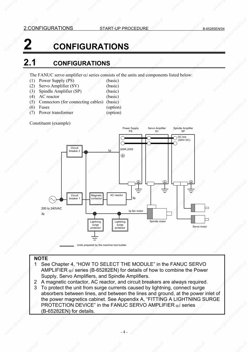
2 CONFIGURATIONS
2.1 CONFIGURATIONS
The FANUC servo amplifier αi series consists of the units and components listed below: (1) Power Supply (PS) (basic) (2) Servo Amplifier (SV) (basic) (3) Spindle Amplifier (SP) (basic) (4) AC reactor (basic) (5) Connectors (for connecting cables) (basic) (6) Fuses (option) (7) Power transformer (option) Constituent (example)
200 to 240VAC
3φ
Power Supply PS
Servo Amplifier SV
Spindle Amplifier SP
AC reactorMagnetic contactor
Circuit breaker 1
Circuit breaker 2
Lightning surge
protector
Lightning surge
protector
Spindle motor
3φ fan motor
Servo motor
1φ
DC link (300V DC)
200R,200S
Units prepared by the machine tool builder
3φ
NOTE 1 See Chapter 4, “HOW TO SELECT THE MODULE” in the FANUC SERVO
AMPLIFIER αi series (B-65282EN) for details of how to combine the Power Supply, Servo Amplifiers, and Spindle Amplifiers.
2 A magnetic contactor, AC reactor, and circuit breakers are always required. 3 To protect the unit from surge currents caused by lightning, connect surge
absorbers between lines, and between the lines and ground, at the power inlet of the power magnetics cabinet. See Appendix A, “FITTING A LIGHTNING SURGE PROTECTION DEVICE” in the FANUC SERVO AMPLIFIER αi series (B-65282EN) for details.
B-65285EN/04 START-UP PROCEDURE 2.CONFIGURATIONS
- 5 -
2.2 MAJOR COMPONENTS
2.2.1 Power Supply
(1) Power Supply (PS, 200VAC-input, power regeneration type) Model Order
specification Unit specification Wiring board specification Printed circuit board specification
αi PS 5.5 A06B-6110-H006 A06B-6110-C006 A16B-2203-0640 A20B-2100-0391(*1) αi PS 11 A06B-6110-H011 A06B-6110-C011 A16B-2203-0641 A20B-2100-0391(*1) αi PS 15 A06B-6110-H015 A06B-6110-C015 A16B-2203-0642 A20B-2100-0391(*1) αi PS 26 A06B-6110-H026 A06B-6110-C026 A16B-2203-0630 A20B-2100-0391(*2) αi PS 30 A06B-6110-H030 A06B-6110-C030 A16B-2203-0631 A20B-2100-0391(*2) αi PS 37 A06B-6110-H037 A06B-6110-C037 A16B-2203-0632 A20B-2100-0391(*2)
αi PS 55 A06B-6110-H055 A06B-6110-C055 A20B-1008-0081
(Driver PCB) A20B-2003-0420 A20B-2100-0391(*2)
αi PS 5.5 A06B-6140-H006 A06B-6140-C006 A16B-2203-0640 A20B-2100-0390 αi PS 11 A06B-6140-H011 A06B-6140-C011 A16B-2203-0641 A20B-2100-0390 αi PS 15 A06B-6140-H015 A06B-6140-C015 A16B-2203-0642 A20B-2100-0390 αi PS 26 A06B-6140-H026 A06B-6140-C026 A16B-2203-0630 A20B-2100-0390 αi PS 30 A06B-6140-H030 A06B-6140-C030 A16B-2203-0631 A20B-2100-0390 αi PS 37 A06B-6140-H037 A06B-6140-C037 A16B-2203-0632 A20B-2100-0390
αi PS 55 A06B-6140-H055 A06B-6140-C055 A20B-1008-0081
(Driver PCB) A20B-2003-0420 A20B-2100-0390
(*1) Old specification: A20B-2100-0760 (*2) Old specification: A20B-2100-0761
(2) Power Supply (PS, 400VAC-input, power regeneration type) Model Order
specification Unit specification Wiring board specification Printed circuit board specification
αi PS 11HV A06B-6120-H011 A06B-6120-C011 A16B-2203-0647 A20B-2100-0391(*1) αi PS 18HV A06B-6120-H018 A06B-6120-C018 A16B-2203-0648 A20B-2100-0391(*1) αi PS 30HV A06B-6120-H030 A06B-6120-C030 A16B-2203-0636 A20B-2100-0391(*2) αi PS 45HV A06B-6120-H045 A06B-6120-C045 A16B-2203-0637 A20B-2100-0391(*2)
αi PS 75HV A06B-6120-H75 A06B-6120-C75 A20B-1008-0086
(Driver PCB) A20B-2003-0420 A20B-2100-0391(*2)
αi PS 100HV A06B-6120-H100 A06B-6120-C100A20B-1008-0087
(Driver PCB) A20B-2003-0420 A20B-2100-0391(*2)
αi PS 11HV A06B-6150-H011 A06B-6150-C011 A16B-2203-0647 A20B-2100-0390 αi PS 18HV A06B-6150-H018 A06B-6150-C018 A16B-2203-0648 A20B-2100-0390 αi PS 30HV A06B-6150-H030 A06B-6150-C030 A16B-2203-0636 A20B-2100-0390 αi PS 45HV A06B-6150-H045 A06B-6150-C045 A16B-2203-0637 A20B-2100-0390 αi PS 60HV A06B-6150-H060 A06B-6150-C060 A16B-2203-0638 A20B-2100-0390
αi PS 75HV A06B-6150-H75 A06B-6150-C75 A20B-1008-0086
(Driver PCB) A20B-2003-0420 A20B-2100-0390
αi PS 100HV A06B-6150-H100 A06B-6150-C100A20B-1008-0087
(Driver PCB) A20B-2003-0420 A20B-2100-0390
(*1) Old specification: A20B-2100-0760 (*2) Old specification: A20B-2100-0761
(3) Power Supply (PSR, 200VAC-input, resistance regeneration type) Model Order specification Unit specification Printed circuit board specification
αi PSR 3 A06B-6115-H003 A06B-6115-C003 A16B-2203-0781 αi PSR 5.5 A06B-6115-H006 A06B-6115-C006 A16B-2203-0782
2.CONFIGURATIONS START-UP PROCEDURE B-65285EN/04
- 6 -
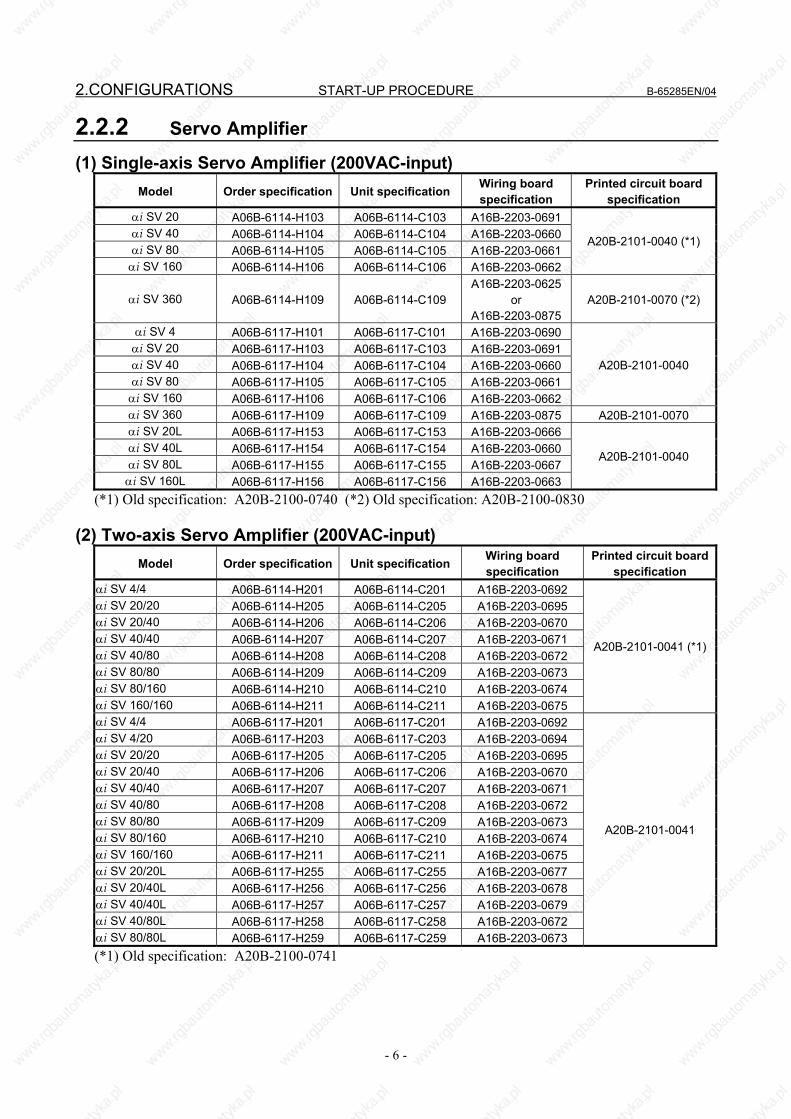
2.2.2 Servo Amplifier
(1) Single-axis Servo Amplifier (200VAC-input) Model Order specification Unit specification Wiring board
specification Printed circuit board
specification αi SV 20 A06B-6114-H103 A06B-6114-C103 A16B-2203-0691 αi SV 40 A06B-6114-H104 A06B-6114-C104 A16B-2203-0660 αi SV 80 A06B-6114-H105 A06B-6114-C105 A16B-2203-0661 αi SV 160 A06B-6114-H106 A06B-6114-C106 A16B-2203-0662
A20B-2101-0040 (*1)
αi SV 360 A06B-6114-H109 A06B-6114-C109 A16B-2203-0625
or A16B-2203-0875
A20B-2101-0070 (*2)
αi SV 4 A06B-6117-H101 A06B-6117-C101 A16B-2203-0690 αi SV 20 A06B-6117-H103 A06B-6117-C103 A16B-2203-0691 αi SV 40 A06B-6117-H104 A06B-6117-C104 A16B-2203-0660 αi SV 80 A06B-6117-H105 A06B-6117-C105 A16B-2203-0661 αi SV 160 A06B-6117-H106 A06B-6117-C106 A16B-2203-0662
A20B-2101-0040
αi SV 360 A06B-6117-H109 A06B-6117-C109 A16B-2203-0875 A20B-2101-0070 αi SV 20L A06B-6117-H153 A06B-6117-C153 A16B-2203-0666 αi SV 40L A06B-6117-H154 A06B-6117-C154 A16B-2203-0660 αi SV 80L A06B-6117-H155 A06B-6117-C155 A16B-2203-0667 αi SV 160L A06B-6117-H156 A06B-6117-C156 A16B-2203-0663
A20B-2101-0040
(*1) Old specification: A20B-2100-0740 (*2) Old specification: A20B-2100-0830
(2) Two-axis Servo Amplifier (200VAC-input) Model Order specification Unit specification Wiring board
specification Printed circuit board
specification αi SV 4/4 A06B-6114-H201 A06B-6114-C201 A16B-2203-0692 αi SV 20/20 A06B-6114-H205 A06B-6114-C205 A16B-2203-0695 αi SV 20/40 A06B-6114-H206 A06B-6114-C206 A16B-2203-0670 αi SV 40/40 A06B-6114-H207 A06B-6114-C207 A16B-2203-0671 αi SV 40/80 A06B-6114-H208 A06B-6114-C208 A16B-2203-0672 αi SV 80/80 A06B-6114-H209 A06B-6114-C209 A16B-2203-0673 αi SV 80/160 A06B-6114-H210 A06B-6114-C210 A16B-2203-0674 αi SV 160/160 A06B-6114-H211 A06B-6114-C211 A16B-2203-0675
A20B-2101-0041 (*1)
αi SV 4/4 A06B-6117-H201 A06B-6117-C201 A16B-2203-0692 αi SV 4/20 A06B-6117-H203 A06B-6117-C203 A16B-2203-0694 αi SV 20/20 A06B-6117-H205 A06B-6117-C205 A16B-2203-0695 αi SV 20/40 A06B-6117-H206 A06B-6117-C206 A16B-2203-0670 αi SV 40/40 A06B-6117-H207 A06B-6117-C207 A16B-2203-0671 αi SV 40/80 A06B-6117-H208 A06B-6117-C208 A16B-2203-0672 αi SV 80/80 A06B-6117-H209 A06B-6117-C209 A16B-2203-0673 αi SV 80/160 A06B-6117-H210 A06B-6117-C210 A16B-2203-0674 αi SV 160/160 A06B-6117-H211 A06B-6117-C211 A16B-2203-0675 αi SV 20/20L A06B-6117-H255 A06B-6117-C255 A16B-2203-0677 αi SV 20/40L A06B-6117-H256 A06B-6117-C256 A16B-2203-0678 αi SV 40/40L A06B-6117-H257 A06B-6117-C257 A16B-2203-0679 αi SV 40/80L A06B-6117-H258 A06B-6117-C258 A16B-2203-0672 αi SV 80/80L A06B-6117-H259 A06B-6117-C259 A16B-2203-0673
A20B-2101-0041
(*1) Old specification: A20B-2100-0741
B-65285EN/04 START-UP PROCEDURE 2.CONFIGURATIONS
- 7 -
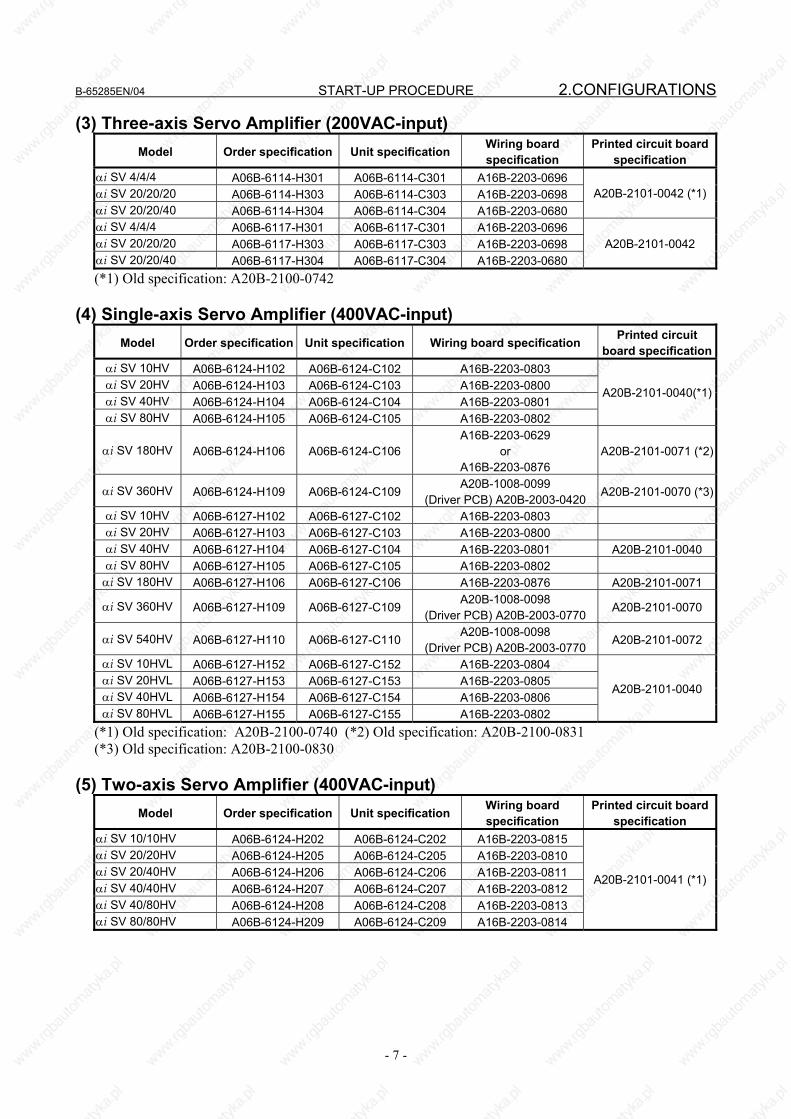
(3) Three-axis Servo Amplifier (200VAC-input) Model Order specification Unit specification Wiring board
specification Printed circuit board
specification αi SV 4/4/4 A06B-6114-H301 A06B-6114-C301 A16B-2203-0696 αi SV 20/20/20 A06B-6114-H303 A06B-6114-C303 A16B-2203-0698 αi SV 20/20/40 A06B-6114-H304 A06B-6114-C304 A16B-2203-0680
A20B-2101-0042 (*1)
αi SV 4/4/4 A06B-6117-H301 A06B-6117-C301 A16B-2203-0696 αi SV 20/20/20 A06B-6117-H303 A06B-6117-C303 A16B-2203-0698 αi SV 20/20/40 A06B-6117-H304 A06B-6117-C304 A16B-2203-0680
A20B-2101-0042
(*1) Old specification: A20B-2100-0742
(4) Single-axis Servo Amplifier (400VAC-input) Model Order specification Unit specification Wiring board specification Printed circuit
board specificationαi SV 10HV A06B-6124-H102 A06B-6124-C102 A16B-2203-0803 αi SV 20HV A06B-6124-H103 A06B-6124-C103 A16B-2203-0800 αi SV 40HV A06B-6124-H104 A06B-6124-C104 A16B-2203-0801 αi SV 80HV A06B-6124-H105 A06B-6124-C105 A16B-2203-0802
A20B-2101-0040(*1)
αi SV 180HV A06B-6124-H106 A06B-6124-C106A16B-2203-0629
or A16B-2203-0876
A20B-2101-0071 (*2)
αi SV 360HV A06B-6124-H109 A06B-6124-C109A20B-1008-0099
(Driver PCB) A20B-2003-0420 A20B-2101-0070 (*3)
αi SV 10HV A06B-6127-H102 A06B-6127-C102 A16B-2203-0803 αi SV 20HV A06B-6127-H103 A06B-6127-C103 A16B-2203-0800 αi SV 40HV A06B-6127-H104 A06B-6127-C104 A16B-2203-0801 A20B-2101-0040 αi SV 80HV A06B-6127-H105 A06B-6127-C105 A16B-2203-0802 αi SV 180HV A06B-6127-H106 A06B-6127-C106 A16B-2203-0876 A20B-2101-0071
αi SV 360HV A06B-6127-H109 A06B-6127-C109A20B-1008-0098
(Driver PCB) A20B-2003-0770 A20B-2101-0070
αi SV 540HV A06B-6127-H110 A06B-6127-C110A20B-1008-0098
(Driver PCB) A20B-2003-0770 A20B-2101-0072
αi SV 10HVL A06B-6127-H152 A06B-6127-C152 A16B-2203-0804 αi SV 20HVL A06B-6127-H153 A06B-6127-C153 A16B-2203-0805 αi SV 40HVL A06B-6127-H154 A06B-6127-C154 A16B-2203-0806 αi SV 80HVL A06B-6127-H155 A06B-6127-C155 A16B-2203-0802
A20B-2101-0040
(*1) Old specification: A20B-2100-0740 (*2) Old specification: A20B-2100-0831 (*3) Old specification: A20B-2100-0830
(5) Two-axis Servo Amplifier (400VAC-input) Model Order specification Unit specification Wiring board
specification Printed circuit board
specification αi SV 10/10HV A06B-6124-H202 A06B-6124-C202 A16B-2203-0815 αi SV 20/20HV A06B-6124-H205 A06B-6124-C205 A16B-2203-0810 αi SV 20/40HV A06B-6124-H206 A06B-6124-C206 A16B-2203-0811 αi SV 40/40HV A06B-6124-H207 A06B-6124-C207 A16B-2203-0812 αi SV 40/80HV A06B-6124-H208 A06B-6124-C208 A16B-2203-0813 αi SV 80/80HV A06B-6124-H209 A06B-6124-C209 A16B-2203-0814
A20B-2101-0041 (*1)
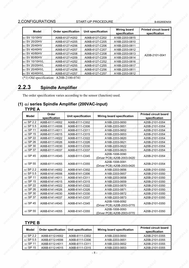
2.CONFIGURATIONS START-UP PROCEDURE B-65285EN/04
- 8 -
Model Order specification Unit specification Wiring board specification
Printed circuit board specification
αi SV 10/10HV A06B-6127-H202 A06B-6127-C202 A16B-2203-0815 αi SV 20/20HV A06B-6127-H205 A06B-6127-C205 A16B-2203-0810 αi SV 20/40HV A06B-6127-H206 A06B-6127-C206 A16B-2203-0811 αi SV 40/40HV A06B-6127-H207 A06B-6127-C207 A16B-2203-0812 αi SV 40/80HV A06B-6127-H208 A06B-6127-C208 A16B-2203-0813 αi SV 80/80HV A06B-6127-H209 A06B-6127-C209 A16B-2203-0814 αi SV 10/10HVL A06B-6127-H252 A06B-6127-C252 A16B-2203-0816 αi SV 20/20HVL A06B-6127-H255 A06B-6127-C255 A16B-2203-0817 αi SV 20/40HVL A06B-6127-H256 A06B-6127-C256 A16B-2203-0811 αi SV 40/40HVL A06B-6127-H257 A06B-6127-C257 A16B-2203-0812
A20B-2101-0041
(*1) Old specification: A20B-2100-0741
2.2.3 Spindle Amplifier The order specification varies according to the sensor (function) used.
(1) αi series Spindle Amplifier (200VAC-input) TYPE A Model Order
specification Unit specification Wiring board specification Printed circuit board specification
αi SP 2.2 A06B-6111-H002 A06B-6111-C002 A16B-2203-0650 A20B-2101-0354 αi SP 5.5 A06B-6111-H006 A06B-6111-C006 A16B-2203-0651 A20B-2101-0354 αi SP 11 A06B-6111-H011 A06B-6111-C011 A16B-2203-0652 A20B-2101-0354 αi SP 15 A06B-6111-H015 A06B-6111-C015 A16B-2203-0653 A20B-2101-0354 αi SP 22 A06B-6111-H022 A06B-6111-C022 A16B-2203-0620 A20B-2101-0354 αi SP 26 A06B-6111-H026 A06B-6111-C026 A16B-2203-0621 A20B-2101-0354 αi SP 30 A06B-6111-H030 A06B-6111-C030 A16B-2203-0622 A20B-2101-0354 αi SP 37 A06B-6111-H037 A06B-6111-C037 A16B-2203-0623 A20B-2101-0354
αi SP 45 A06B-6111-H045 A06B-6111-C045 A20B-1008-0090
(Driver PCB) A20B-2003-0420 A20B-2101-0354
αi SP 55 A06B-6111-H055 A06B-6111-C055 A20B-1008-0091
(Driver PCB) A20B-2003-0420 A20B-2101-0354
αi SP 2.2 A06B-6141-H002 A06B-6141-C002 A16B-2203-0656 A20B-2101-0350 αi SP 5.5 A06B-6141-H006 A06B-6141-C006 A16B-2203-0657 A20B-2101-0350 αi SP 11 A06B-6141-H011 A06B-6141-C011 A16B-2203-0658 A20B-2101-0350 αi SP 15 A06B-6141-H015 A06B-6141-C015 A16B-2203-0659 A20B-2101-0350 αi SP 22 A06B-6141-H022 A06B-6141-C022 A16B-2203-0870 A20B-2101-0350 αi SP 26 A06B-6141-H026 A06B-6141-C026 A16B-2203-0871 A20B-2101-0350 αi SP 30 A06B-6141-H030 A06B-6141-C030 A16B-2203-0872 A20B-2101-0350 αi SP 37 A06B-6141-H037 A06B-6141-C037 A16B-2203-0873 A20B-2101-0350
αi SP 45 A06B-6141-H045 A06B-6141-C045 A20B-1008-0092
(Driver PCB) A20B-2003-0770 A20B-2101-0350
αi SP 55 A06B-6141-H055 A06B-6141-C055 A20B-1008-0093
(Driver PCB) A20B-2003-0770 A20B-2101-0350
TYPE B
Model Order specification Unit specification Wiring board specification Printed circuit board specification
αi SP 2.2 A06B-6112-H002 A06B-6111-C002 A16B-2203-0650 A20B-2101-0355 αi SP 5.5 A06B-6112-H006 A06B-6111-C006 A16B-2203-0651 A20B-2101-0355 αi SP 11 A06B-6112-H011 A06B-6111-C011 A16B-2203-0652 A20B-2101-0355 αi SP 15 A06B-6112-H015 A06B-6111-C015 A16B-2203-0653 A20B-2101-0355
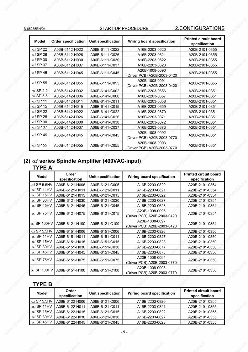
B-65285EN/04 START-UP PROCEDURE 2.CONFIGURATIONS
- 9 -
Model Order specification Unit specification Wiring board specification Printed circuit board specification
αi SP 22 A06B-6112-H022 A06B-6111-C022 A16B-2203-0620 A20B-2101-0355 αi SP 26 A06B-6112-H026 A06B-6111-C026 A16B-2203-0621 A20B-2101-0355 αi SP 30 A06B-6112-H030 A06B-6111-C030 A16B-2203-0622 A20B-2101-0355 αi SP 37 A06B-6112-H037 A06B-6111-C037 A16B-2203-0623 A20B-2101-0355
αi SP 45 A06B-6112-H045 A06B-6111-C045A20B-1008-0090
(Driver PCB) A20B-2003-0420 A20B-2101-0355
αi SP 55 A06B-6112-H055 A06B-6111-C055A20B-1008-0091
(Driver PCB) A20B-2003-0420 A20B-2101-0355
αi SP 2.2 A06B-6142-H002 A06B-6141-C002 A16B-2203-0656 A20B-2101-0351 αi SP 5.5 A06B-6142-H006 A06B-6141-C006 A16B-2203-0657 A20B-2101-0351 αi SP 11 A06B-6142-H011 A06B-6141-C011 A16B-2203-0658 A20B-2101-0351 αi SP 15 A06B-6142-H015 A06B-6141-C015 A16B-2203-0659 A20B-2101-0351 αi SP 22 A06B-6142-H022 A06B-6141-C022 A16B-2203-0870 A20B-2101-0351 αi SP 26 A06B-6142-H026 A06B-6141-C026 A16B-2203-0871 A20B-2101-0351 αi SP 30 A06B-6142-H030 A06B-6141-C030 A16B-2203-0872 A20B-2101-0351 αi SP 37 A06B-6142-H037 A06B-6141-C037 A16B-2203-0873 A20B-2101-0351
αi SP 45 A06B-6142-H045 A06B-6141-C045A20B-1008-0092
(Driver PCB) A20B-2003-0770 A20B-2101-0351
αi SP 55 A06B-6142-H055 A06B-6141-C055A20B-1008-0093
(Driver PCB) A20B-2003-0770 A20B-2101-0351
(2) αi series Spindle Amplifier (400VAC-input) TYPE A
Model Order specification Unit specification Wiring board specification Printed circuit board
specification αi SP 5.5HV A06B-6121-H006 A06B-6121-C006 A16B-2203-0820 A20B-2101-0354 αi SP 11HV A06B-6121-H011 A06B-6121-C011 A16B-2203-0821 A20B-2101-0354 αi SP 15HV A06B-6121-H015 A06B-6121-C015 A16B-2203-0822 A20B-2101-0354 αi SP 30HV A06B-6121-H030 A06B-6121-C030 A16B-2203-0627 A20B-2101-0354 αi SP 45HV A06B-6121-H045 A06B-6121-C045 A16B-2203-0628 A20B-2101-0354
αi SP 75HV A06B-6121-H075 A06B-6121-C075A20B-1008-0096
(Driver PCB) A20B-2003-0420 A20B-2101-0354
αi SP 100HV A06B-6121-H100 A06B-6121-C100A20B-1008-0097
(Driver PCB) A20B-2003-0420 A20B-2101-0354
αi SP 5.5HV A06B-6151-H006 A06B-6151-C006 A16B-2203-0826 A20B-2101-0350 αi SP 11HV A06B-6151-H011 A06B-6151-C011 A16B-2203-0827 A20B-2101-0350 αi SP 15HV A06B-6151-H015 A06B-6151-C015 A16B-2203-0828 A20B-2101-0350 αi SP 30HV A06B-6151-H030 A06B-6151-C030 A16B-2203-0877 A20B-2101-0350 αi SP 45HV A06B-6151-H045 A06B-6151-C045 A16B-2203-0878 A20B-2101-0350
αi SP 75HV A06B-6151-H075 A06B-6151-C075A20B-1008-0094
(Driver PCB) A20B-2003-0770 A20B-2101-0350
αi SP 100HV A06B-6151-H100 A06B-6151-C100A20B-1008-0095
(Driver PCB) A20B-2003-0770 A20B-2101-0350
TYPE B
Model Order specification Unit specification Wiring board specification Printed circuit board
specification αi SP 5.5HV A06B-6122-H006 A06B-6121-C006 A16B-2203-0820 A20B-2101-0355 αi SP 11HV A06B-6122-H011 A06B-6121-C011 A16B-2203-0821 A20B-2101-0355 αi SP 15HV A06B-6122-H015 A06B-6121-C015 A16B-2203-0822 A20B-2101-0355 αi SP 30HV A06B-6122-H030 A06B-6121-C030 A16B-2203-0627 A20B-2101-0355 αi SP 45HV A06B-6122-H045 A06B-6121-C045 A16B-2203-0628 A20B-2101-0355
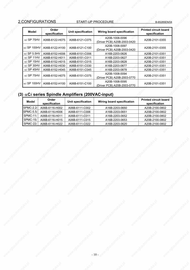
2.CONFIGURATIONS START-UP PROCEDURE B-65285EN/04
- 10 -
Model Order specification Unit specification Wiring board specification Printed circuit board
specification
αi SP 75HV A06B-6122-H075 A06B-6121-C075A20B-1008-0096
(Driver PCB) A20B-2003-0420 A20B-2101-0355
αi SP 100HV A06B-6122-H100 A06B-6121-C100A20B-1008-0097
(Driver PCB) A20B-2003-0420 A20B-2101-0355
αi SP 5.5HV A06B-6152-H006 A06B-6151-C006 A16B-2203-0826 A20B-2101-0351 αi SP 11HV A06B-6152-H011 A06B-6151-C011 A16B-2203-0827 A20B-2101-0351 αi SP 15HV A06B-6152-H015 A06B-6151-C015 A16B-2203-0828 A20B-2101-0351 αi SP 30HV A06B-6152-H030 A06B-6151-C030 A16B-2203-0877 A20B-2101-0351 αi SP 45HV A06B-6152-H045 A06B-6151-C045 A16B-2203-0878 A20B-2101-0351
αi SP 75HV A06B-6152-H075 A06B-6151-C075A20B-1008-0094
(Driver PCB) A20B-2003-0770 A20B-2101-0351
αi SP 100HV A06B-6152-H100 A06B-6151-C100A20B-1008-0095
(Driver PCB) A20B-2003-0770 A20B-2101-0351
(3) αCi series Spindle Amplifiers (200VAC-input)
Model Order specification Unit specification Wiring board specification Printed circuit board
specification SPMC-2.2i A06B-6116-H002 A06B-6111-C002 A16B-2203-0650 A20B-2100-0802 SPMC-5.5i A06B-6116-H006 A06B-6111-C006 A16B-2203-0651 A20B-2100-0802 SPMC-11i A06B-6116-H011 A06B-6111-C011 A16B-2203-0652 A20B-2100-0802 SPMC-15i A06B-6116-H015 A06B-6111-C015 A16B-2203-0653 A20B-2100-0802 SPMC-22i A06B-6116-H022 A06B-6111-C022 A16B-2203-0620 A20B-2100-0802
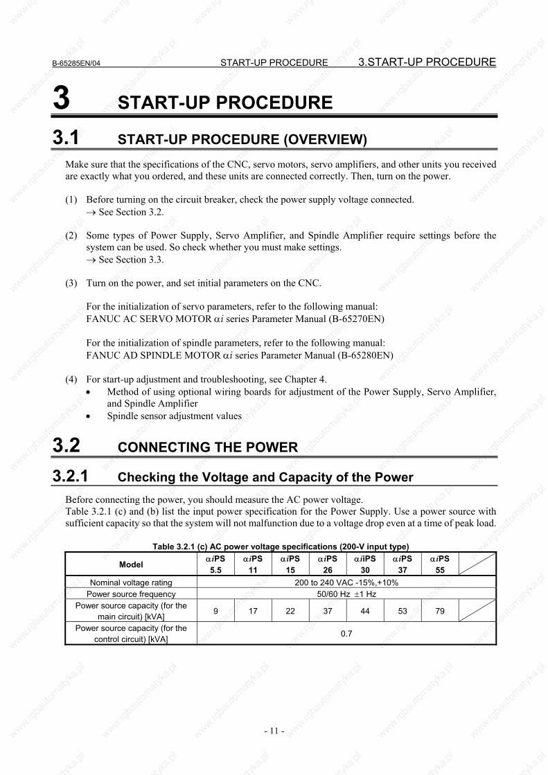
B-65285EN/04 START-UP PROCEDURE 3.START-UP PROCEDURE
- 11 -
3 START-UP PROCEDURE
3.1 START-UP PROCEDURE (OVERVIEW) Make sure that the specifications of the CNC, servo motors, servo amplifiers, and other units you received are exactly what you ordered, and these units are connected correctly. Then, turn on the power. (1) Before turning on the circuit breaker, check the power supply voltage connected. → See Section 3.2. (2) Some types of Power Supply, Servo Amplifier, and Spindle Amplifier require settings before the
system can be used. So check whether you must make settings. → See Section 3.3. (3) Turn on the power, and set initial parameters on the CNC. For the initialization of servo parameters, refer to the following manual: FANUC AC SERVO MOTOR αi series Parameter Manual (B-65270EN) For the initialization of spindle parameters, refer to the following manual: FANUC AD SPINDLE MOTOR αi series Parameter Manual (B-65280EN) (4) For start-up adjustment and troubleshooting, see Chapter 4.
• Method of using optional wiring boards for adjustment of the Power Supply, Servo Amplifier, and Spindle Amplifier
• Spindle sensor adjustment values
3.2 CONNECTING THE POWER
3.2.1 Checking the Voltage and Capacity of the Power Before connecting the power, you should measure the AC power voltage. Table 3.2.1 (c) and (b) list the input power specification for the Power Supply. Use a power source with sufficient capacity so that the system will not malfunction due to a voltage drop even at a time of peak load.
Table 3.2.1 (c) AC power voltage specifications (200-V input type)
Model αiPS 5.5
αiPS 11
αiPS 15
αiPS 26
αiiPS30
αiPS 37
αiPS 55
Nominal voltage rating 200 to 240 VAC -15%,+10% Power source frequency 50/60 Hz ±1 Hz
Power source capacity (for the main circuit) [kVA]
9 17 22 37 44 53 79
Power source capacity (for the control circuit) [kVA]
0.7
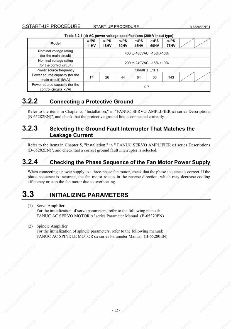
3.START-UP PROCEDURE START-UP PROCEDURE B-65285EN/04
- 12 -
Table 3.2.1 (d) AC power voltage specifications (200-V input type)
Model αiPS 11HV
αiPS 18HV
αiPS 30HV
αiPS 45HV
αiPS 60HV
αiPS 75HV
Nominal voltage rating (for the main circuit)
400 to 480VAC -15%,+10%
Nominal voltage rating (for the control circuit)
200 to 240VAC -15%,+10%
Power source frequency 50/60Hz ±1Hz Power source capacity (for the
main circuit) [kVA] 17 26 44 64 86 143
Power source capacity (for the control circuit) [kVA]
0.7
3.2.2 Connecting a Protective Ground Refer to the items in Chapter 5, "Installation," in "FANUC SERVO AMPLIFIER αi series Descriptions (B-65282EN)", and check that the protective ground line is connected correctly.
3.2.3 Selecting the Ground Fault Interrupter That Matches the Leakage Current
Refer to the items in Chapter 5, "Installation," in " FANUC SERVO AMPLIFIER αi series Descriptions (B-65282EN)", and check that a correct ground fault interrupter is selected.
3.2.4 Checking the Phase Sequence of the Fan Motor Power Supply When connecting a power supply to a three-phase fan motor, check that the phase sequence is correct. If the phase sequence is incorrect, the fan motor rotates in the reverse direction, which may decrease cooling efficiency or stop the fan motor due to overheating.
3.3 INITIALIZING PARAMETERS (1) Servo Amplifier For the initialization of servo parameters, refer to the following manual: FANUC AC SERVO MOTOR αi series Parameter Manual (B-65270EN) (2) Spindle Amplifier For the initialization of spindle parameters, refer to the following manual: FANUC AC SPINDLE MOTOR αi series Parameter Manual (B-65280EN)

B-65285EN/04 START-UP PROCEDURE
- 13 -
4.CONFIRMATION OF THEOPERATION
4 CONFIRMATION OF THE OPERATION
4.1 POWER SUPPLY Check each item according to the procedure described below.
5. Check the operation of the servo and spindle motors.
See Subsec. 4.1.4.
OK NG
4. Make sure that the MCC is turned on.
3. Release the system from emergency stop state.
OK Alarm occurs.
See Section 3.1 of Part II.
2. Check the STATUS LEDs. See Section 4.1.1.
1. Supply control power (200 VAC) to the Power Supply at the
emergency stop state.
Alarm occurs.
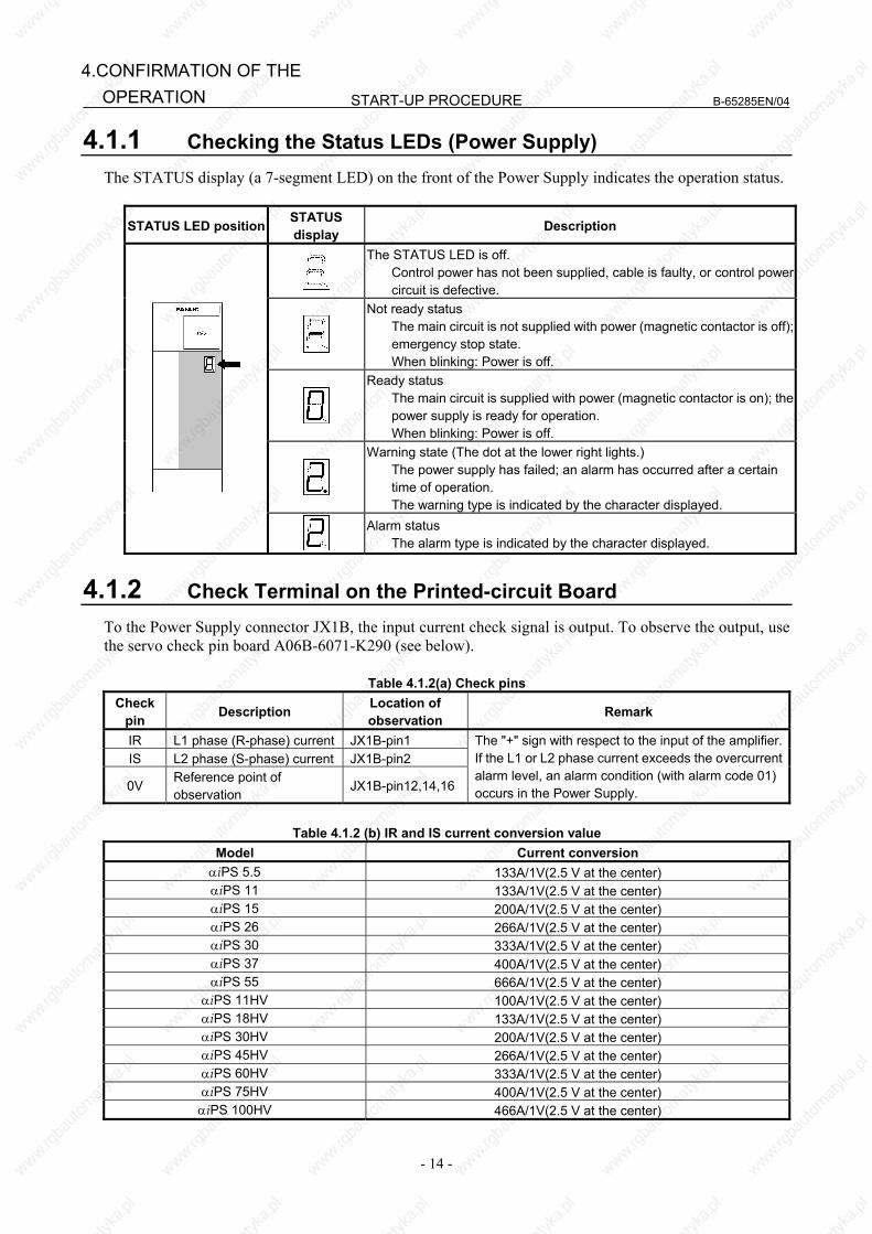
START-UP PROCEDURE B-65285EN/04
- 14 -
4.CONFIRMATION OF THE OPERATION
4.1.1 Checking the Status LEDs (Power Supply) The STATUS display (a 7-segment LED) on the front of the Power Supply indicates the operation status.
STATUS LED position STATUS display Description
The STATUS LED is off. Control power has not been supplied, cable is faulty, or control power
circuit is defective.
Not ready status The main circuit is not supplied with power (magnetic contactor is off);
emergency stop state. When blinking: Power is off.
Ready status The main circuit is supplied with power (magnetic contactor is on); the
power supply is ready for operation. When blinking: Power is off.
Warning state (The dot at the lower right lights.) The power supply has failed; an alarm has occurred after a certain
time of operation. The warning type is indicated by the character displayed.
Alarm status The alarm type is indicated by the character displayed.
4.1.2 Check Terminal on the Printed-circuit Board To the Power Supply connector JX1B, the input current check signal is output. To observe the output, use the servo check pin board A06B-6071-K290 (see below).
Table 4.1.2(a) Check pins Check
pin Description Location of observation Remark
IR L1 phase (R-phase) current JX1B-pin1 IS L2 phase (S-phase) current JX1B-pin2
0V Reference point of observation
JX1B-pin12,14,16
The "+" sign with respect to the input of the amplifier.If the L1 or L2 phase current exceeds the overcurrent alarm level, an alarm condition (with alarm code 01) occurs in the Power Supply.
Table 4.1.2 (b) IR and IS current conversion value
Model Current conversion αiPS 5.5 133A/1V(2.5 V at the center) αiPS 11 133A/1V(2.5 V at the center) αiPS 15 200A/1V(2.5 V at the center) αiPS 26 266A/1V(2.5 V at the center) αiPS 30 333A/1V(2.5 V at the center) αiPS 37 400A/1V(2.5 V at the center) αiPS 55 666A/1V(2.5 V at the center)
αiPS 11HV 100A/1V(2.5 V at the center) αiPS 18HV 133A/1V(2.5 V at the center) αiPS 30HV 200A/1V(2.5 V at the center) αiPS 45HV 266A/1V(2.5 V at the center) αiPS 60HV 333A/1V(2.5 V at the center) αiPS 75HV 400A/1V(2.5 V at the center) αiPS 100HV 466A/1V(2.5 V at the center)
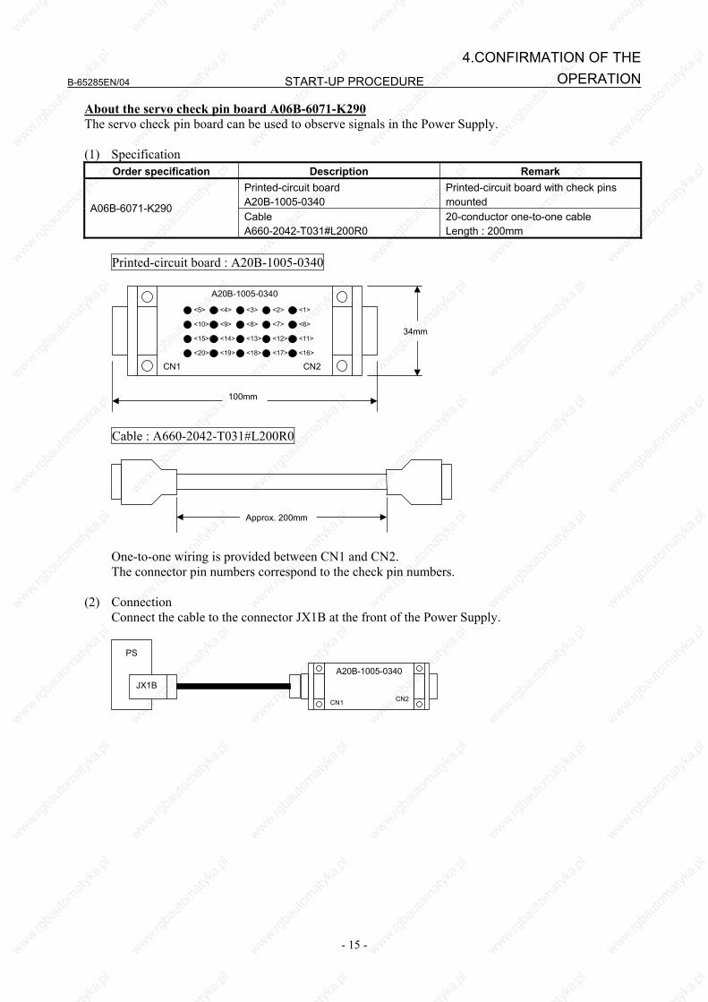
B-65285EN/04 START-UP PROCEDURE
- 15 -
4.CONFIRMATION OF THEOPERATION
About the servo check pin board A06B-6071-K290 The servo check pin board can be used to observe signals in the Power Supply. (1) Specification
Order specification Description Remark Printed-circuit board A20B-1005-0340
Printed-circuit board with check pins mounted A06B-6071-K290
Cable A660-2042-T031#L200R0
20-conductor one-to-one cable Length : 200mm
Printed-circuit board : A20B-1005-0340
A20B-1005-0340
100mm
34mm
CN1 CN2
<5>
<10>
<20>
<15>
<4>
<9>
<19>
<14>
<3>
<8>
<18>
<13>
<2>
<7>
<17>
<12>
<1>
<6>
<16>
<11>
Cable : A660-2042-T031#L200R0
Approx. 200mm
One-to-one wiring is provided between CN1 and CN2. The connector pin numbers correspond to the check pin numbers. (2) Connection Connect the cable to the connector JX1B at the front of the Power Supply.
PS
JX1B A20B-1005-0340
CN1 CN2
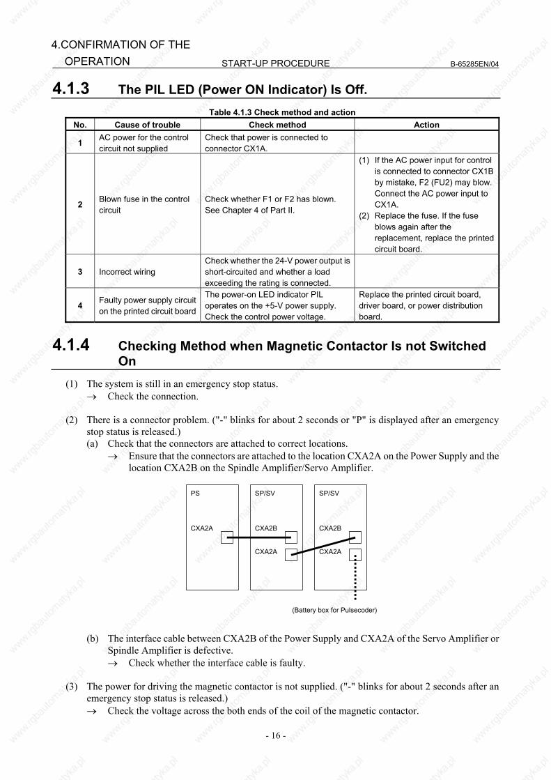
START-UP PROCEDURE B-65285EN/04
- 16 -
4.CONFIRMATION OF THE OPERATION
4.1.3 The PIL LED (Power ON Indicator) Is Off. Table 4.1.3 Check method and action
No. Cause of trouble Check method Action
1 AC power for the control circuit not supplied
Check that power is connected to connector CX1A.
2 Blown fuse in the control circuit
Check whether F1 or F2 has blown. See Chapter 4 of Part II.
(1) If the AC power input for control is connected to connector CX1B by mistake, F2 (FU2) may blow. Connect the AC power input to CX1A.
(2) Replace the fuse. If the fuse blows again after the replacement, replace the printed circuit board.
3 Incorrect wiring Check whether the 24-V power output is short-circuited and whether a load exceeding the rating is connected.
4 Faulty power supply circuit on the printed circuit board
The power-on LED indicator PIL operates on the +5-V power supply. Check the control power voltage.
Replace the printed circuit board, driver board, or power distribution board.
4.1.4 Checking Method when Magnetic Contactor Is not Switched On
(1) The system is still in an emergency stop status. → Check the connection.
(2) There is a connector problem. ("-" blinks for about 2 seconds or "P" is displayed after an emergency
stop status is released.) (a) Check that the connectors are attached to correct locations.
→ Ensure that the connectors are attached to the location CXA2A on the Power Supply and the location CXA2B on the Spindle Amplifier/Servo Amplifier.
CXA2A
PS
CXA2B
SP/SV
CXA2A
CXA2B
SP/SV
CXA2A
(Battery box for Pulsecoder)
(b) The interface cable between CXA2B of the Power Supply and CXA2A of the Servo Amplifier or
Spindle Amplifier is defective. → Check whether the interface cable is faulty.
(3) The power for driving the magnetic contactor is not supplied. ("-" blinks for about 2 seconds after an
emergency stop status is released.) → Check the voltage across the both ends of the coil of the magnetic contactor.
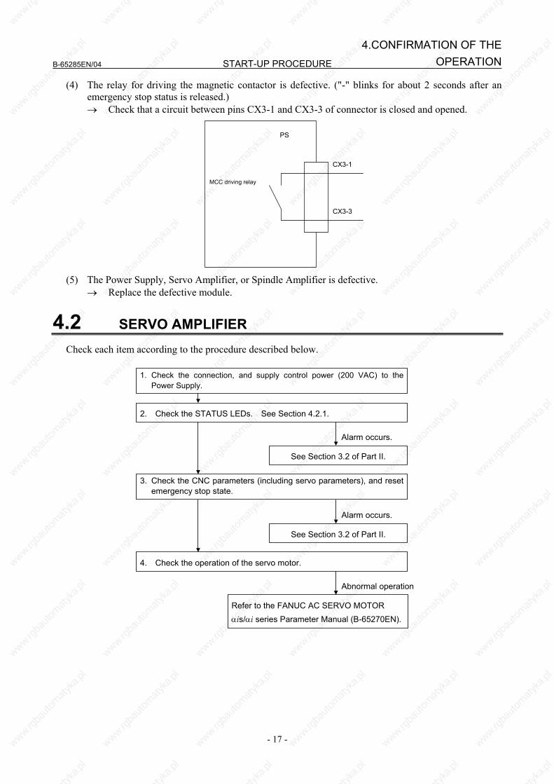
B-65285EN/04 START-UP PROCEDURE
- 17 -
4.CONFIRMATION OF THEOPERATION
(4) The relay for driving the magnetic contactor is defective. ("-" blinks for about 2 seconds after an emergency stop status is released.) → Check that a circuit between pins CX3-1 and CX3-3 of connector is closed and opened.
PS
MCC driving relay
CX3-1
CX3-3
(5) The Power Supply, Servo Amplifier, or Spindle Amplifier is defective.
→ Replace the defective module.
4.2 SERVO AMPLIFIER Check each item according to the procedure described below.
Alarm occurs.
See Section 3.2 of Part II.
2. Check the STATUS LEDs. See Section 4.2.1.
1. Check the connection, and supply control power (200 VAC) to thePower Supply.
3. Check the CNC parameters (including servo parameters), and resetemergency stop state.
Alarm occurs.
See Section 3.2 of Part II.
4. Check the operation of the servo motor.
Abnormal operation
Refer to the FANUC AC SERVO MOTOR αis/αi series Parameter Manual (B-65270EN).
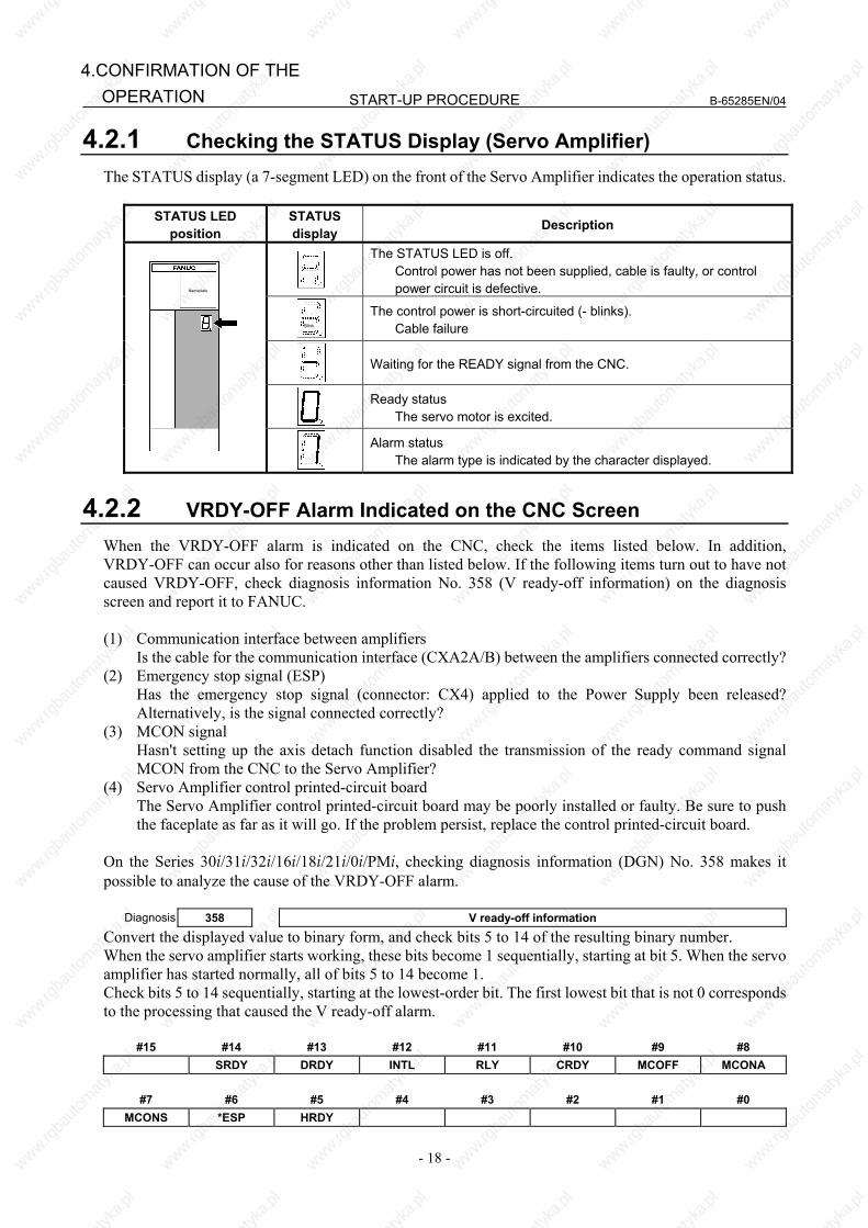
START-UP PROCEDURE B-65285EN/04
- 18 -
4.CONFIRMATION OF THE OPERATION
4.2.1 Checking the STATUS Display (Servo Amplifier) The STATUS display (a 7-segment LED) on the front of the Servo Amplifier indicates the operation status.
STATUS LED position
STATUS display Description
The STATUS LED is off. Control power has not been supplied, cable is faulty, or control
power circuit is defective.
Blink
The control power is short-circuited (- blinks). Cable failure
Waiting for the READY signal from the CNC.
Ready status The servo motor is excited.
Nameplate
Alarm status The alarm type is indicated by the character displayed.
4.2.2 VRDY-OFF Alarm Indicated on the CNC Screen When the VRDY-OFF alarm is indicated on the CNC, check the items listed below. In addition, VRDY-OFF can occur also for reasons other than listed below. If the following items turn out to have not caused VRDY-OFF, check diagnosis information No. 358 (V ready-off information) on the diagnosis screen and report it to FANUC. (1) Communication interface between amplifiers Is the cable for the communication interface (CXA2A/B) between the amplifiers connected correctly? (2) Emergency stop signal (ESP) Has the emergency stop signal (connector: CX4) applied to the Power Supply been released?
Alternatively, is the signal connected correctly? (3) MCON signal Hasn't setting up the axis detach function disabled the transmission of the ready command signal
MCON from the CNC to the Servo Amplifier? (4) Servo Amplifier control printed-circuit board The Servo Amplifier control printed-circuit board may be poorly installed or faulty. Be sure to push
the faceplate as far as it will go. If the problem persist, replace the control printed-circuit board. On the Series 30i/31i/32i/16i/18i/21i/0i/PMi, checking diagnosis information (DGN) No. 358 makes it possible to analyze the cause of the VRDY-OFF alarm.
Diagnosis 358 V ready-off information
Convert the displayed value to binary form, and check bits 5 to 14 of the resulting binary number. When the servo amplifier starts working, these bits become 1 sequentially, starting at bit 5. When the servo amplifier has started normally, all of bits 5 to 14 become 1. Check bits 5 to 14 sequentially, starting at the lowest-order bit. The first lowest bit that is not 0 corresponds to the processing that caused the V ready-off alarm.
#15 #14 #13 #12 #11 #10 #9 #8 SRDY DRDY INTL RLY CRDY MCOFF MCONA
#7 #6 #5 #4 #3 #2 #1 #0
MCONS *ESP HRDY
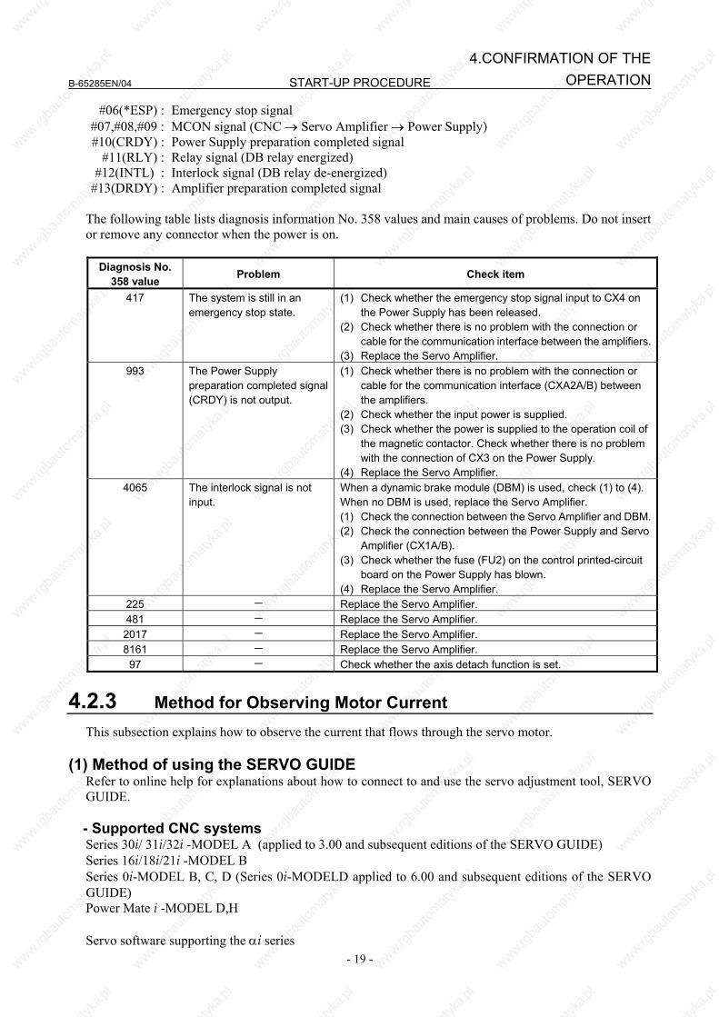
B-65285EN/04 START-UP PROCEDURE
- 19 -
4.CONFIRMATION OF THEOPERATION
#06(*ESP) : Emergency stop signal #07,#08,#09 : MCON signal (CNC → Servo Amplifier → Power Supply) #10(CRDY) : Power Supply preparation completed signal #11(RLY) : Relay signal (DB relay energized) #12(INTL) : Interlock signal (DB relay de-energized) #13(DRDY) : Amplifier preparation completed signal
The following table lists diagnosis information No. 358 values and main causes of problems. Do not insert or remove any connector when the power is on.
Diagnosis No. 358 value Problem Check item
417 The system is still in an emergency stop state.
(1) Check whether the emergency stop signal input to CX4 on the Power Supply has been released.
(2) Check whether there is no problem with the connection or cable for the communication interface between the amplifiers.
(3) Replace the Servo Amplifier. 993 The Power Supply
preparation completed signal (CRDY) is not output.
(1) Check whether there is no problem with the connection or cable for the communication interface (CXA2A/B) between the amplifiers.
(2) Check whether the input power is supplied. (3) Check whether the power is supplied to the operation coil of
the magnetic contactor. Check whether there is no problem with the connection of CX3 on the Power Supply.
(4) Replace the Servo Amplifier. 4065 The interlock signal is not
input. When a dynamic brake module (DBM) is used, check (1) to (4). When no DBM is used, replace the Servo Amplifier. (1) Check the connection between the Servo Amplifier and DBM.(2) Check the connection between the Power Supply and Servo
Amplifier (CX1A/B). (3) Check whether the fuse (FU2) on the control printed-circuit
board on the Power Supply has blown. (4) Replace the Servo Amplifier.
225 - Replace the Servo Amplifier. 481 - Replace the Servo Amplifier. 2017 - Replace the Servo Amplifier. 8161 - Replace the Servo Amplifier. 97 - Check whether the axis detach function is set.
4.2.3 Method for Observing Motor Current This subsection explains how to observe the current that flows through the servo motor.
(1) Method of using the SERVO GUIDE Refer to online help for explanations about how to connect to and use the servo adjustment tool, SERVO GUIDE.
- Supported CNC systems Series 30i/ 31i/32i -MODEL A (applied to 3.00 and subsequent editions of the SERVO GUIDE) Series 16i/18i/21i -MODEL B Series 0i-MODEL B, C, D (Series 0i-MODELD applied to 6.00 and subsequent editions of the SERVO GUIDE) Power Mate i -MODEL D,H Servo software supporting the αi series
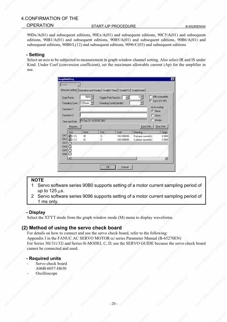
START-UP PROCEDURE B-65285EN/04
- 20 -
4.CONFIRMATION OF THE OPERATION
90Dx/A(01) and subsequent editions, 90Ex/A(01) and subsequent editions, 90C5/A(01) and subsequent editions, 90B1/A(01) and subsequent editions, 90B5/A(01) and subsequent editions, 90B6/A(01) and subsequent editions, 90B0/L(12) and subsequent editions, 9096/C(03) and subsequent editions
- Setting Select an axis to be subjected to measurement in graph window channel setting. Also select IR and IS under Kind. Under Coef (conversion coefficient), set the maximum allowable current (Ap) for the amplifier in use.
NOTE 1 Servo software series 90B0 supports setting of a motor current sampling period of
up to 125 μs. 2 Servo software series 9096 supports setting of a motor current sampling period of
1 ms only.
- Display Select the XTYT mode from the graph window mode (M) menu to display waveforms.
(2) Method of using the servo check board For details on how to connect and use the servo check board, refer to the following: Appendix I in the FANUC AC SERVO MOTOR αi series Parameter Manual (B-65270EN) For Series 30i/31i/32i and Series 0i-MODEL C, D, use the SERVO GUIDE because the servo check board cannot be connected and used.
- Required units - Servo check board A06B-6057-H630 - Oscilloscope
B-65285EN/04 START-UP PROCEDURE
- 21 -
4.CONFIRMATION OF THEOPERATION
- Settings ⋅ CNC setting
Parameter setting for servo software series 90B0
Output channel Data number 5 Data number 6 FS15i No.1726 No.1774 No.1775 No.1776
FS16i/18i/21i/0i/PMi No.2115 No.2151 No.2152 No.2153 Measurement axis/ current
phase IR IS
L-axis (Note 1) 370 0 402 0 M-axis (Note 1) 2418 0 2450 0
Parameter setting for servo software series 9096
Output channel Data number 5 Data number 6 FS16i/18i/21i/0i/PMi No.2115 No.2115
Measurement axis/ current phase IR IS
L-axis (Note 1) 370 402 M-axis (Note 1) 1010 1042
When series 9096 is used, if no axis is paired with the measurement axis (Note 2), IR and IS cannot be observed simultaneously.
NOTE 1 The L-axis is an axis identified with an odd number set in parameter No. 1023. The
M-axis is an axis identified with an even number set in parameter No. 1023. 2 The axis specified as 2n-1 in parameter No. 1023 and the axis specified as 2n will
be in a pair. Setting the output period of motor current data (for the 90B0 series only)
Output period Parameter No. 1746 / Bit 7 of parameter No. 2206
Velocity loop period 0 (default) Current loop period 1 (Note 3)
NOTE 3 If the current loop period is set up as the motor current data output period,
selecting data number 0, 1, 2, or 4 disables the output of signals (such as a velocity command) to channels. To observe the motor current and other signals (such as a velocity command), specify the output period as 1 ms.
4 For the servo software series 9096, the output period of the motor current is only 1 ms. The current loop period cannot be used for output.
⋅ Setting up the check board
- Set the AXIS digit of the LED display with an axis number from 1 to 8 specified in parameter No. 1023.
- Set the DATA digit of the LED display with a data number from 5 to 6.
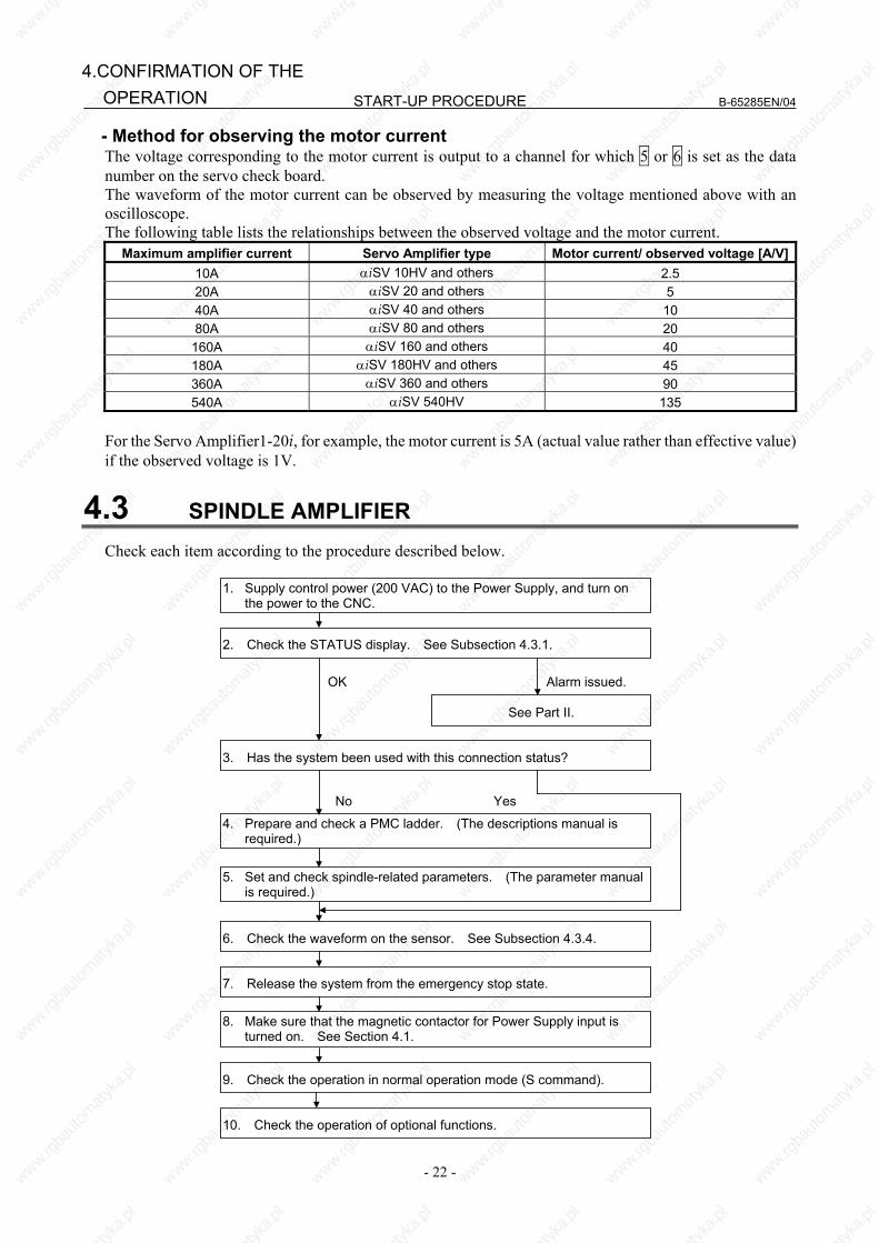
START-UP PROCEDURE B-65285EN/04
- 22 -
4.CONFIRMATION OF THE OPERATION
- Method for observing the motor current The voltage corresponding to the motor current is output to a channel for which 5 or 6 is set as the data number on the servo check board. The waveform of the motor current can be observed by measuring the voltage mentioned above with an oscilloscope. The following table lists the relationships between the observed voltage and the motor current.
Maximum amplifier current Servo Amplifier type Motor current/ observed voltage [A/V]10A αiSV 10HV and others 2.5 20A αiSV 20 and others 5 40A αiSV 40 and others 10 80A αiSV 80 and others 20 160A αiSV 160 and others 40 180A αiSV 180HV and others 45 360A αiSV 360 and others 90 540A αiSV 540HV 135
For the Servo Amplifier1-20i, for example, the motor current is 5A (actual value rather than effective value) if the observed voltage is 1V.
4.3 SPINDLE AMPLIFIER Check each item according to the procedure described below.
9. Check the operation in normal operation mode (S command).
8. Make sure that the magnetic contactor for Power Supply input is turned on. See Section 4.1.
7. Release the system from the emergency stop state.
6. Check the waveform on the sensor. See Subsection 4.3.4.
5. Set and check spindle-related parameters. (The parameter manual is required.)
No Yes
4. Prepare and check a PMC ladder. (The descriptions manual is required.)
3. Has the system been used with this connection status?
OK Alarm issued.
See Part II.
2. Check the STATUS display. See Subsection 4.3.1.
1. Supply control power (200 VAC) to the Power Supply, and turn on the power to the CNC.
10. Check the operation of optional functions.
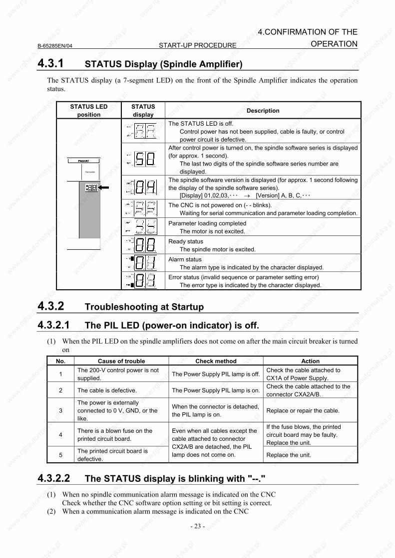
B-65285EN/04 START-UP PROCEDURE
- 23 -
4.CONFIRMATION OF THEOPERATION
4.3.1 STATUS Display (Spindle Amplifier) The STATUS display (a 7-segment LED) on the front of the Spindle Amplifier indicates the operation status.
STATUS LED position
STATUS display Description
The STATUS LED is off. Control power has not been supplied, cable is faulty, or control
power circuit is defective.
After control power is turned on, the spindle software series is displayed (for approx. 1 second). The last two digits of the spindle software series number are
displayed.
The spindle software version is displayed (for approx. 1 second following the display of the spindle software series). [Display] 01,02,03,・・・ → [Version] A, B, C,・・・
Blink Blink
The CNC is not powered on (- - blinks). Waiting for serial communication and parameter loading completion.
Parameter loading completed The motor is not excited.
Ready status The spindle motor is excited.
Alarm status The alarm type is indicated by the character displayed.
Nameplate
Error status (invalid sequence or parameter setting error) The error type is indicated by the character displayed.
4.3.2 Troubleshooting at Startup
4.3.2.1 The PIL LED (power-on indicator) is off. (1) When the PIL LED on the spindle amplifiers does not come on after the main circuit breaker is turned
on No. Cause of trouble Check method Action
1 The 200-V control power is not supplied.
The Power Supply PIL lamp is off.Check the cable attached to CX1A of Power Supply.
2 The cable is defective. The Power Supply PIL lamp is on.Check the cable attached to the connector CXA2A/B.
3 The power is externally connected to 0 V, GND, or the like.
When the connector is detached, the PIL lamp is on.
Replace or repair the cable.
4 There is a blown fuse on the printed circuit board.
If the fuse blows, the printed circuit board may be faulty. Replace the unit.
5 The printed circuit board is defective.
Even when all cables except the cable attached to connector CX2A/B are detached, the PIL lamp does not come on. Replace the unit.
4.3.2.2 The STATUS display is blinking with "--."
(1) When no spindle communication alarm message is indicated on the CNC Check whether the CNC software option setting or bit setting is correct. (2) When a communication alarm message is indicated on the CNC
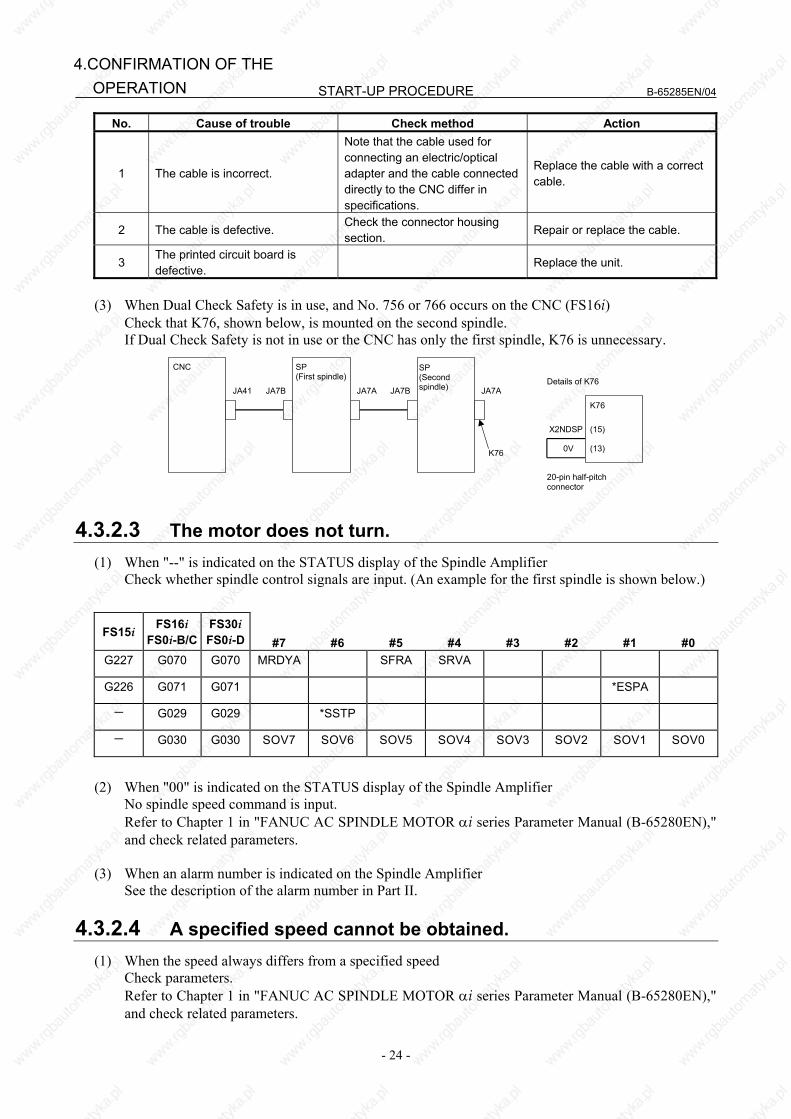
START-UP PROCEDURE B-65285EN/04
- 24 -
4.CONFIRMATION OF THE OPERATION
No. Cause of trouble Check method Action
1 The cable is incorrect.
Note that the cable used for connecting an electric/optical adapter and the cable connected directly to the CNC differ in specifications.
Replace the cable with a correct cable.
2 The cable is defective. Check the connector housing section.
Repair or replace the cable.
3 The printed circuit board is defective.
Replace the unit.
(3) When Dual Check Safety is in use, and No. 756 or 766 occurs on the CNC (FS16i) Check that K76, shown below, is mounted on the second spindle. If Dual Check Safety is not in use or the CNC has only the first spindle, K76 is unnecessary.
SP (First spindle)
CNC
JA41 JA7B JA7A JA7B
K76
JA7A
SP (Second spindle)
X2NDSP
0V
(15)
(13)
K76
20-pin half-pitchconnector
Details of K76
4.3.2.3 The motor does not turn. (1) When "--" is indicated on the STATUS display of the Spindle Amplifier Check whether spindle control signals are input. (An example for the first spindle is shown below.)
FS15i FS16i FS0i-B/C
FS30iFS0i-D #7 #6 #5 #4 #3 #2 #1 #0
G227 G070 G070 MRDYA SFRA SRVA
G226 G071 G071 *ESPA
- G029 G029 *SSTP
- G030 G030 SOV7 SOV6 SOV5 SOV4 SOV3 SOV2 SOV1 SOV0
(2) When "00" is indicated on the STATUS display of the Spindle Amplifier No spindle speed command is input. Refer to Chapter 1 in "FANUC AC SPINDLE MOTOR αi series Parameter Manual (B-65280EN),"
and check related parameters. (3) When an alarm number is indicated on the Spindle Amplifier See the description of the alarm number in Part II.
4.3.2.4 A specified speed cannot be obtained. (1) When the speed always differs from a specified speed Check parameters. Refer to Chapter 1 in "FANUC AC SPINDLE MOTOR αi series Parameter Manual (B-65280EN),"
and check related parameters.
B-65285EN/04 START-UP PROCEDURE
- 25 -
4.CONFIRMATION OF THEOPERATION
(2) When an alarm number is indicated on the Spindle Amplifier See the description of the alarm number in Part II.
4.3.2.5 When cutting is not performed, the spindle vibrates, making noise.
(1) The spindle vibrates only when the spindle speed has reached or is at a particular speed level. Check whether the spindle also vibrates when the motor is turning by inertia. If noise is unchanged,
investigate the source of mechanical vibration. There are several methods to turn the spindle by inertia as explained below. Because these methods involve machine sequences, consult with the machine tool builder. A. Setting spindle control signal MPOF (FS16i: G73#2, FS15i: G228#2) to 1 immediately causes
the spindle to turn by inertia. B. Set ALSP (FS16i: bit 2 of parameter No. 4009, FS15i: bit 2 of parameter No. 3009) to 1. Then,
when the power to the CNC is turned off during spindle rotation, the spindle turns by inertia. (On the spindle amplifier, Alarm 24 is indicated.)
(2) When noise is generated at the time the motor is stopped or at any time
A. See Subsection 4.3.4 of this part, and check and adjust the waveform of the spindle sensor. B. Check that the motor part number matches its parameters. For details, refer to Appendix A in
"FANUC AC SPINDLE MOTOR αi series Parameter Manual (B-65280EN)." C. Adjust the velocity loop gain and so forth. For details, refer to Chapter 1 in "FANUC AC SPINDLE MOTOR αi series Parameter Manual
(B-65280EN)."
4.3.2.6 An overshoot or hunting occurs. Refer to Chapter 1 in "FANUC AC SPINDLE MOTOR αi series Parameter Manual (B-65280EN)," and adjust parameters.
4.3.2.7 Cutting power weakens or acceleration/deceleration slows down.
(1) When the load meter does not indicate the maximum output A. A mechanical cause such as a belt slip may occur.
(2) When the load meter indicates the maximum output
A. Check whether the torque limit signal is input incorrectly.
FS15i FS16i FS0i-B/C
FS30iFS0i-D #7 #6 #5 #4 #3 #2 #1 #0
G227 G070 G070 TLMHA TLMLA
B. If you are using the αi BZ sensor, it is likely that a slip has occurred between the sensor gear and spindle (on acceleration).
C. Check that the motor part number matches its parameters. For details, refer to Appendix A in "FANUC AC SPINDLE MOTOR αi series Parameter Manual
(B-65280EN)." D. Check whether the output limit pattern is set incorrectly. For details, refer to Chapter 1 in "FANUC AC SPINDLE MOTOR αi series Parameter Manual
(B-65280EN)."

START-UP PROCEDURE B-65285EN/04
- 26 -
4.CONFIRMATION OF THE OPERATION
4.3.3 Status Error Indication Function When there is a sequence or parameter error, the error LED (yellow) in the display section of the Spindle Amplifier (SP) goes on with an error code displayed. This can ease troubleshooting at the time of machine startup.
The error LED (yellow) lights.
An error code is indicated. (from 01)
Status
The error code is also displayed on the CNC diagnosis screen.
Diagnosis No.
FS15i FS16i FS30i FS0i-D
Description
1561
710(First spindle)711(Second spindle)730(Third spindle)
731(Fourth spindle)
710 Status error code
When the Spindle Amplifier does not operate for a certain function, check whether the status error is indicated in the display section of the Spindle Amplifier or CNC diagnosis screen.
No. Description Action
01
Although neither *ESP (emergency stop signal) (there are two types of signals, a PMC signal and Power Supply (PS) contact signal) nor MRDY (machine ready signal) has been input, SFR (forward rotation signal), SRV (reverse rotation signal), or ORCM (orientation command) is input.
Check the *ESP and MRDY sequences. For MRDY, pay attention to the parameter that specifies whether to use the MRDY signal (bit 0 of parameter No. 4001).
03
Although parameter settings are such that that there is no position sensor (position control is not to be performed, that is, bits 3, 2, 1, and 0 of parameter No. 4002 are, respectively, 0, 0, 0, and 0), a Cs axis contour control command has been issued. In this case, the motor is not activated.
Check setting of the parameter.
04
Although parameter settings are such that that there is no position sensor (position control is not to be performed, that is, bits 3, 2, 1, and 0 of parameter No. 4002 are, respectively, 0, 0, 0, and 0), a servo mode (such as rigid tapping or Cs axis control) command or spindle synchronization control command has been issued. In this case, the motor is not activated.
Check setting of the parameter.
05 Although optional parameter for the orientation function is not set, an ORCM (orientation command) is input.
Check setting of the parameter for orientation.
06 Although optional parameter for the output switching option is not set, low-speed winding is selected (RCH = 1).
Check setting of the parameter for output switching and the power line status signal (RCH).
07 Although Cs contour control mode is input, neither SFR (forward rotation signal) nor SRV (reverse rotation signal) is input.
Check the sequence.
08 Although servo mode (rigid tapping or spindle positioning) control command is input, neither SFR (forward rotation signal) nor SRV (reverse rotation signal) is input.
Check the sequence.
B-65285EN/04 START-UP PROCEDURE
- 27 -
4.CONFIRMATION OF THEOPERATION
No. Description Action
09 Although spindle synchronization control command is input, neither SFR (forward rotation signal) nor SRV (reverse rotation signal) is input.
Check the sequence.
10 Although Cs contour control command is input, another operation mode (servo mode, spindle synchronization, or orientation) is specified.
Do not specify another mode during execution of the Cs contour control command. Before entering another mode, cancel the Cs contour control command.
11 Although servo mode (rigid tapping or spindle positioning) is input, another operation mode (Cs contour control, spindle synchronization, or orientation) is specified.
Do not specify another mode during execution of the servo mode command. Before entering another mode, cancel servo mode.
12 Although spindle synchronization is input, another operation mode (Cs contour control, servo mode, or orientation) is specified.
Do not specify another mode during execution of the spindle synchronization command. Before entering another mode, cancel the spindle synchronization command.
13 Although orientation specification is input, another operation mode (Cs contour control, servo mode, or synchronization control) is specified.
Do not specify another mode during execution of the orientation command. Before entering another mode, cancel the orientation command.
14 The SFR (forward rotation signal) and SRV (reverse rotation signal) are input at the same time.
Input one of the SFR and SRV signals.
16 Although the parameter not to use the differential speed control function (bit 5 of parameter No. 4000 = 0) is set, DEFMD (differential speed mode command) is input.
Check the setting of the parameter and the differential speed mode command.
17 The parameter settings for the speed detector (bits 2, 1, and 0 of parameter No. 4011) are invalid. There is no speed detector that matches the settings.
Check the setting of the parameter.
18
Although parameter settings are such that that there is no position sensor (position control is not to be performed, that is, "bits 3, 2, 1, and 0 of parameter No. 4002 are, respectively, 0, 0, 0, and 0," a position coder-based orientation command has been issued.
Check the setting of the parameter and the input signal.
19 Although magnetic sensor orientation command is input, another operation mode (Cs contour control, servo mode, or spindle synchronization) is specified.
Do not specify another mode during execution of the orientation command. Before entering another mode, cancel the orientation command.
21 The tandem operation command was input in the spindle synchronization control enable state.
Input the tandem operation command when spindle synchronization control is canceled.
22 Spindle synchronization control was specified in the tandem operation enable state.
Specify spindle synchronization control when torque tandem operation is canceled.
23 The tandem operation command is input without the required option.
Torque tandem control requires a CNC software option. Check the option.
24
Although continuous indexing in position coder-based orientation is to be performed, an absolute position command (INCMD = 0) has been issued after incremental operation (INCMD = 1).
Check the INCMD (incremental command). Be sure to perform absolute position command-based orientation before an absolute position command.
26 The parameter settings are such that both spindle switch and three-stage speed range switch are used.
Check the parameter settings and the input signal.
29 Parameter settings are such that the shortest-time orientation function is to be used (bit 6 of parameter No. 4018 is 0 and parameter Nos. 4320 to 4323 are nonzero).
The shortest-time orientation function cannot be used in the αi series spindle amplifier. The use of the optimum orientation function is recommended.
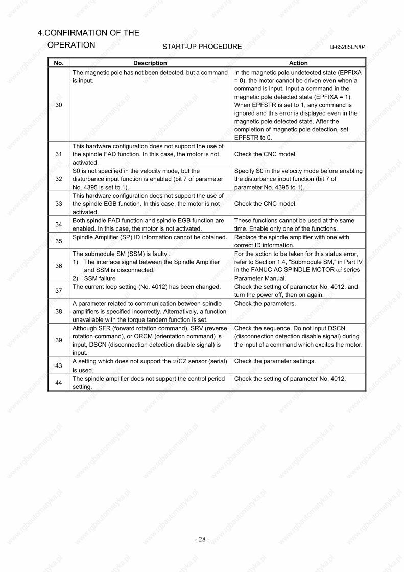
START-UP PROCEDURE B-65285EN/04
- 28 -
4.CONFIRMATION OF THE OPERATION
No. Description Action
30
The magnetic pole has not been detected, but a command is input.
In the magnetic pole undetected state (EPFIXA = 0), the motor cannot be driven even when a command is input. Input a command in the magnetic pole detected state (EPFIXA = 1). When EPFSTR is set to 1, any command is ignored and this error is displayed even in the magnetic pole detected state. After the completion of magnetic pole detection, set EPFSTR to 0.
31 This hardware configuration does not support the use of the spindle FAD function. In this case, the motor is not activated.
Check the CNC model.
32 S0 is not specified in the velocity mode, but the disturbance input function is enabled (bit 7 of parameter No. 4395 is set to 1).
Specify S0 in the velocity mode before enabling the disturbance input function (bit 7 of parameter No. 4395 to 1).
33 This hardware configuration does not support the use of the spindle EGB function. In this case, the motor is not activated.
Check the CNC model.
34 Both spindle FAD function and spindle EGB function are enabled. In this case, the motor is not activated.
These functions cannot be used at the same time. Enable only one of the functions.
35 Spindle Amplifier (SP) ID information cannot be obtained. Replace the spindle amplifier with one with
correct ID information.
36
The submodule SM (SSM) is faulty . 1) The interface signal between the Spindle Amplifier
and SSM is disconnected. 2) SSM failure
For the action to be taken for this status error, refer to Section 1.4, "Submodule SM," in Part IV in the FANUC AC SPINDLE MOTOR αi series Parameter Manual.
37 The current loop setting (No. 4012) has been changed. Check the setting of parameter No. 4012, and
turn the power off, then on again.
38 A parameter related to communication between spindle amplifiers is specified incorrectly. Alternatively, a function unavailable with the torque tandem function is set.
Check the parameters.
39
Although SFR (forward rotation command), SRV (reverse rotation command), or ORCM (orientation command) is input, DSCN (disconnection detection disable signal) is input.
Check the sequence. Do not input DSCN (disconnection detection disable signal) during the input of a command which excites the motor.
43 A setting which does not support the αiCZ sensor (serial) is used.
Check the parameter settings.
44 The spindle amplifier does not support the control period setting.
Check the setting of parameter No. 4012.
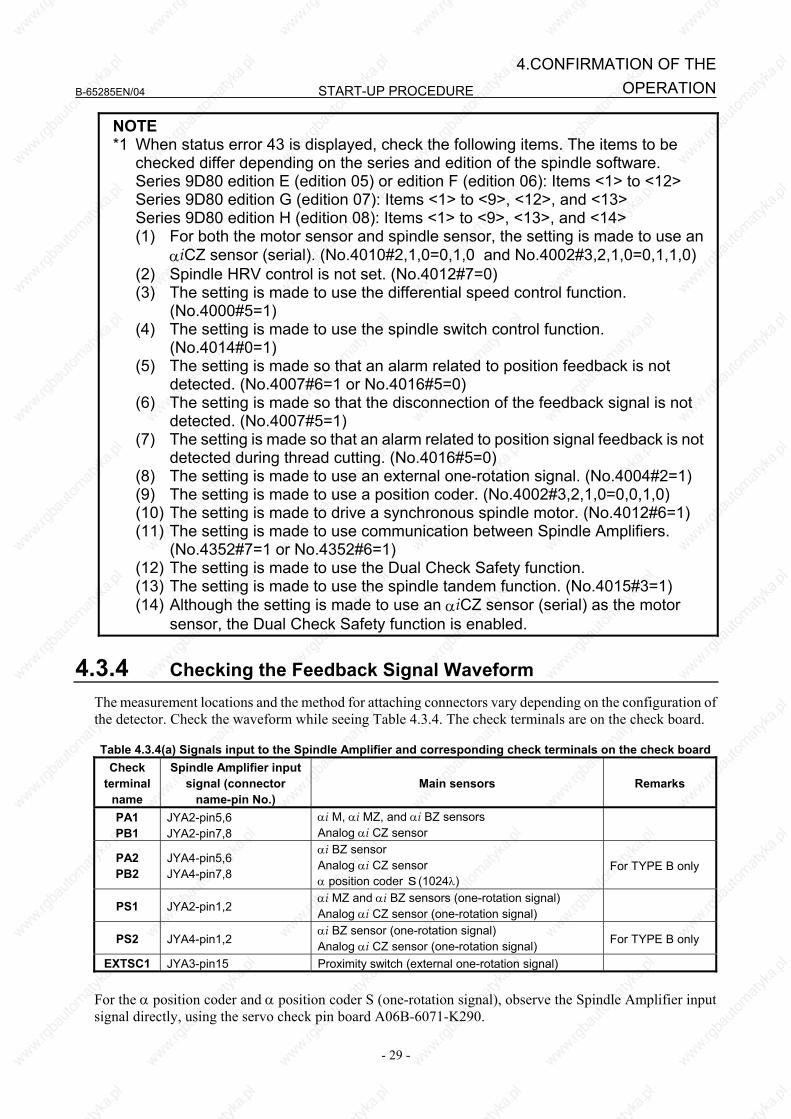
B-65285EN/04 START-UP PROCEDURE
- 29 -
4.CONFIRMATION OF THEOPERATION
NOTE *1 When status error 43 is displayed, check the following items. The items to be
checked differ depending on the series and edition of the spindle software. Series 9D80 edition E (edition 05) or edition F (edition 06): Items <1> to <12> Series 9D80 edition G (edition 07): Items <1> to <9>, <12>, and <13> Series 9D80 edition H (edition 08): Items <1> to <9>, <13>, and <14>
(1) For both the motor sensor and spindle sensor, the setting is made to use an αiCZ sensor (serial). (No.4010#2,1,0=0,1,0 and No.4002#3,2,1,0=0,1,1,0)
(2) Spindle HRV control is not set. (No.4012#7=0) (3) The setting is made to use the differential speed control function.
(No.4000#5=1) (4) The setting is made to use the spindle switch control function.
(No.4014#0=1) (5) The setting is made so that an alarm related to position feedback is not
detected. (No.4007#6=1 or No.4016#5=0) (6) The setting is made so that the disconnection of the feedback signal is not
detected. (No.4007#5=1) (7) The setting is made so that an alarm related to position signal feedback is not
detected during thread cutting. (No.4016#5=0) (8) The setting is made to use an external one-rotation signal. (No.4004#2=1) (9) The setting is made to use a position coder. (No.4002#3,2,1,0=0,0,1,0) (10) The setting is made to drive a synchronous spindle motor. (No.4012#6=1) (11) The setting is made to use communication between Spindle Amplifiers.
(No.4352#7=1 or No.4352#6=1) (12) The setting is made to use the Dual Check Safety function. (13) The setting is made to use the spindle tandem function. (No.4015#3=1) (14) Although the setting is made to use an αiCZ sensor (serial) as the motor
sensor, the Dual Check Safety function is enabled.
4.3.4 Checking the Feedback Signal Waveform
The measurement locations and the method for attaching connectors vary depending on the configuration of the detector. Check the waveform while seeing Table 4.3.4. The check terminals are on the check board. Table 4.3.4(a) Signals input to the Spindle Amplifier and corresponding check terminals on the check board
Check terminal
name
Spindle Amplifier input signal (connector
name-pin No.) Main sensors Remarks
PA1 PB1
JYA2-pin5,6 JYA2-pin7,8
αi M, αi MZ, and αi BZ sensors Analog αi CZ sensor
PA2 PB2
JYA4-pin5,6 JYA4-pin7,8
αi BZ sensor Analog αi CZ sensor α position coder S(1024λ)
For TYPE B only
PS1 JYA2-pin1,2 αi MZ and αi BZ sensors (one-rotation signal) Analog αi CZ sensor (one-rotation signal)
PS2 JYA4-pin1,2 αi BZ sensor (one-rotation signal) Analog αi CZ sensor (one-rotation signal) For TYPE B only
EXTSC1 JYA3-pin15 Proximity switch (external one-rotation signal) For the α position coder and α position coder S (one-rotation signal), observe the Spindle Amplifier input signal directly, using the servo check pin board A06B-6071-K290.

START-UP PROCEDURE B-65285EN/04
- 30 -
4.CONFIRMATION OF THE OPERATION
4.3.4.1 αi M sensor, αi MZ sensor, and αi BZ sensor
Measurement location
Measurement condition Sample waveform
PA1, PB1 Separate sensors PA2, PB2 PS1 Separate sensor PS2
The speed must be 1500 min-1 or less. Rotation direction: CW
Detection gear
Motor
CW
PA1 (PA2)
PB1 (PB2)
Vpp
VphaseVoffs
0 V
Waveforms of phaseA and phase B
Vrip
PA1, PB1 (PA2, PB2)
Ripples of phase A andphase B
For αi MZ and αi BZ sensors only
(Z - *Z)
Voffz
0 V
Vpz
Waveform ofphase Z
Measurement item Specification Measurement method Adjustment method Vpp 0.5 to 1.2 Vp-p
Voffs, Voffsz 2.5 V ±100 mV Use the DC range of a digital voltmeter.
Vphase 90 ±3° Vrip < 70 mV Vpz > 0.5 V
Normally, the αi M and αi MZ sensors need not be adjusted. For Voffs and Voffz, only level check is possible, but adjustment is not possible.
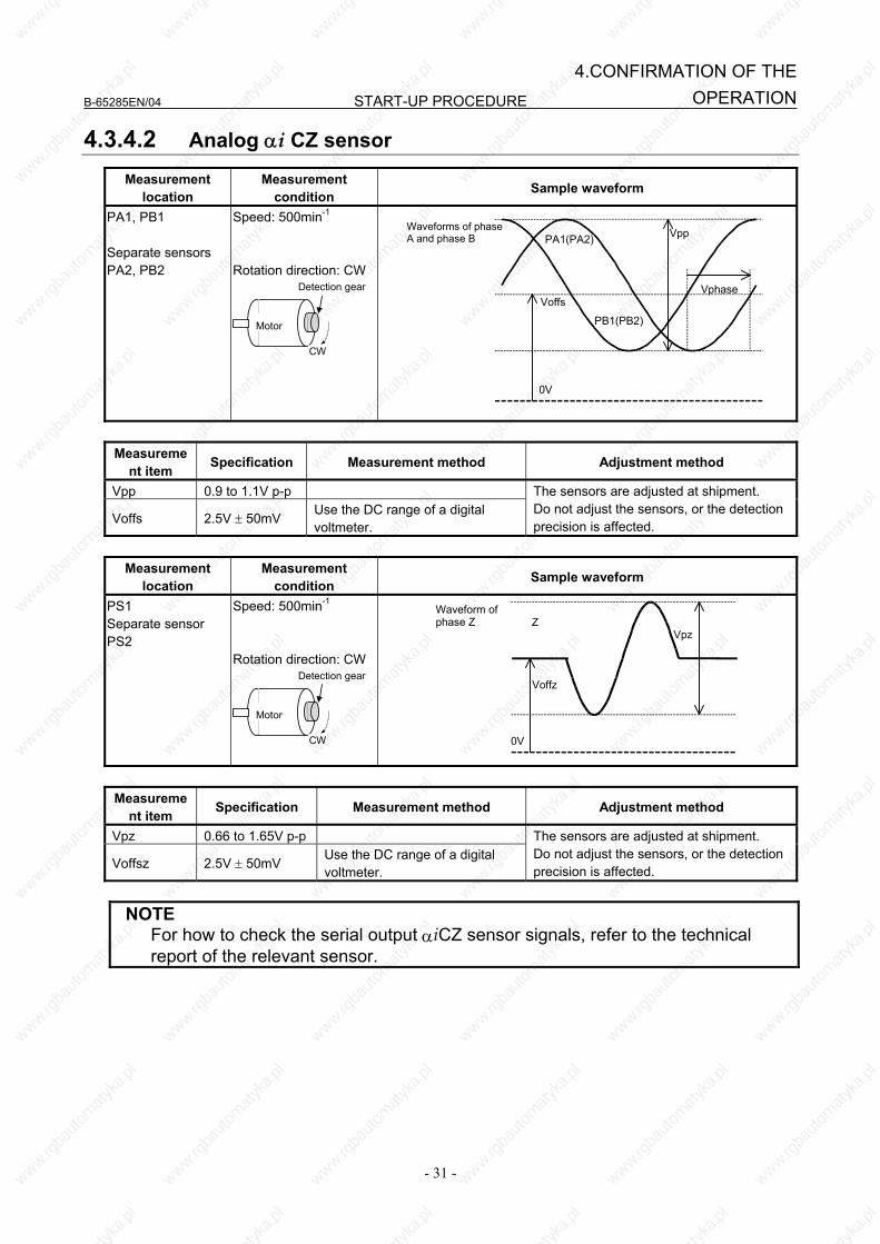
B-65285EN/04 START-UP PROCEDURE
- 31 -
4.CONFIRMATION OF THEOPERATION
4.3.4.2 Analog αi CZ sensor
Measurement location
Measurement condition Sample waveform
PA1, PB1 Separate sensors PA2, PB2
Speed: 500min-1
Rotation direction: CW
Detection gear
Motor
CW
PA1(PA2)
PB1(PB2)
Vpp
VphaseVoffs
0V
Waveforms of phase A and phase B
Measureme
nt item Specification Measurement method Adjustment method
Vpp 0.9 to 1.1V p-p
Voffs 2.5V ± 50mV Use the DC range of a digital voltmeter.
The sensors are adjusted at shipment. Do not adjust the sensors, or the detection precision is affected.
Measurement
location Measurement
condition Sample waveform
PS1 Separate sensor PS2
Speed: 500min-1
Rotation direction: CW
Detection gear
Motor
CW
Z
Voffz
0V
Vpz
Waveform of phase Z
Measurement item Specification Measurement method Adjustment method
Vpz 0.66 to 1.65V p-p
Voffsz 2.5V ± 50mV Use the DC range of a digital voltmeter.
The sensors are adjusted at shipment. Do not adjust the sensors, or the detection precision is affected.
NOTE For how to check the serial output αiCZ sensor signals, refer to the technical
report of the relevant sensor.
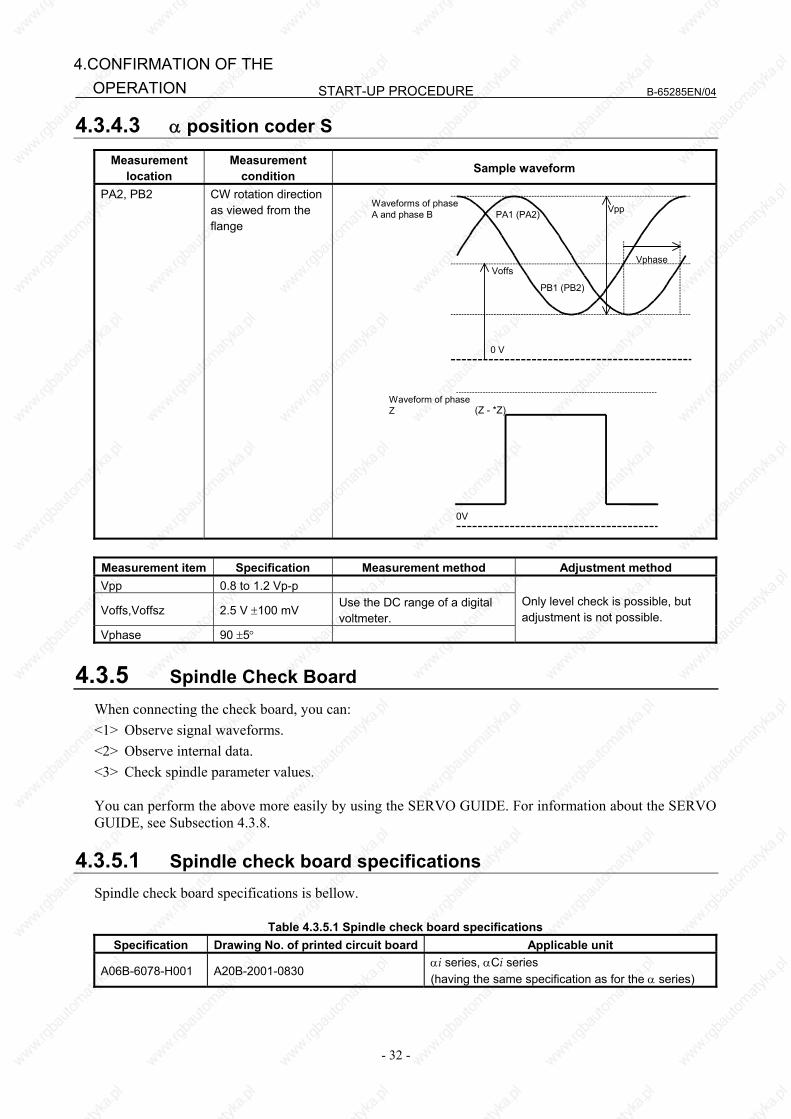
START-UP PROCEDURE B-65285EN/04
- 32 -
4.CONFIRMATION OF THE OPERATION
4.3.4.3 α position coder S Measurement
location Measurement
condition Sample waveform
PA2, PB2 CW rotation direction as viewed from the flange
PA1 (PA2)
PB1 (PB2)
Vpp
VphaseVoffs
0 V
Waveforms of phaseA and phase B
(Z - *Z)
0V
Waveform of phaseZ
Measurement item Specification Measurement method Adjustment method Vpp 0.8 to 1.2 Vp-p
Voffs,Voffsz 2.5 V ±100 mV Use the DC range of a digital voltmeter.
Vphase 90 ±5°
Only level check is possible, but adjustment is not possible.
4.3.5 Spindle Check Board When connecting the check board, you can: <1> Observe signal waveforms. <2> Observe internal data. <3> Check spindle parameter values. You can perform the above more easily by using the SERVO GUIDE. For information about the SERVO GUIDE, see Subsection 4.3.8.
4.3.5.1 Spindle check board specifications Spindle check board specifications is bellow.
Table 4.3.5.1 Spindle check board specifications Specification Drawing No. of printed circuit board Applicable unit
A06B-6078-H001 A20B-2001-0830 αi series, αCi series (having the same specification as for the α series)

B-65285EN/04 START-UP PROCEDURE
- 33 -
4.CONFIRMATION OF THEOPERATION
4.3.5.2 Check board connection (1) αi series
JY1B JX4B
JY1A JX4A
JX4
Spindle check board
A20B-2001-0830
Output equivalent to JX4
Output equivalent to JY1
SP
JY1
(2) αCi series
JY1B JX4B
JY1A JX4A Spindlecheckboard
A20B-2001-0830
SPMC
JY1
Output equivalent to JY1
4.3.5.3 Check terminal output signals (1) αi series
Check terminal Signal name Check
terminal Signal name
LM Load meter signal PA1 Phase A sine wave signal 1 SM Speedometer signal PB1 Phase B sine wave signal 1
CH1 Analog output for internal data observation (Phase U current: IU)
PS1 Phase Z sine wave signal 1
CH2 Analog output for internal data observation (Motor speed TSA: 1638 min-1/V)
PA2 Phase A sine wave signal 2 (TYPE B)
CH1D Output for internal data bit observation PB2 Phase B sine wave signal 2 (TYPE B)CH2D Output for internal data bit observation PS2 Phase Z sine wave signal 2 (TYPE B)VRM Disuse PA3 Disuse LSA1 Disuse PB3 Disuse
EXTSC1 External one-rotation signal (main) PA4 Disuse LSA2 Disuse PB4 Disuse

START-UP PROCEDURE B-65285EN/04
- 34 -
4.CONFIRMATION OF THE OPERATION
Check terminal Signal name Check
terminal Signal name
EXTSC2 Disuse OVR2 Analog override command
PAD Phase A of position coder signal output (TYPE B)
15V Disuse
PBD Phase B of position coder signal output (TYPE B)
5V +5 VDC power check
PSD Phase Z of position coder signal output (TYPE B)
-15V Disuse
GND 0 V (2) αCi series
Check terminal Signal name Check
terminal Signal name
LM Speedometer signal (This can be switched to the load meter signal by parameter setting.)
PA1 Disuse
SM Disuse PB1 Disuse
CH1 Analog output for internal data observation (Phase U current: IU)
PS1 Disuse
CH2 Analog output for internal data observation (Estimated motor speed : 1638 min-1/V)
PA2 Disuse
CH1D Output for internal data bit observation PB2 Disuse CH2D Output for internal data bit observation PS2 Disuse VRM Disuse PA3 Disuse LSA1 Disuse PB3 Disuse
EXTSC1 Disuse PA4 Disuse LSA2 Disuse PB4 Disuse
EXTSC2 Disuse OVR2 Analog override command PAD Disuse 15V Disuse PBD Disuse 5V +5 VDC power check PSD Disuse -15V Disuse
GND 0 V
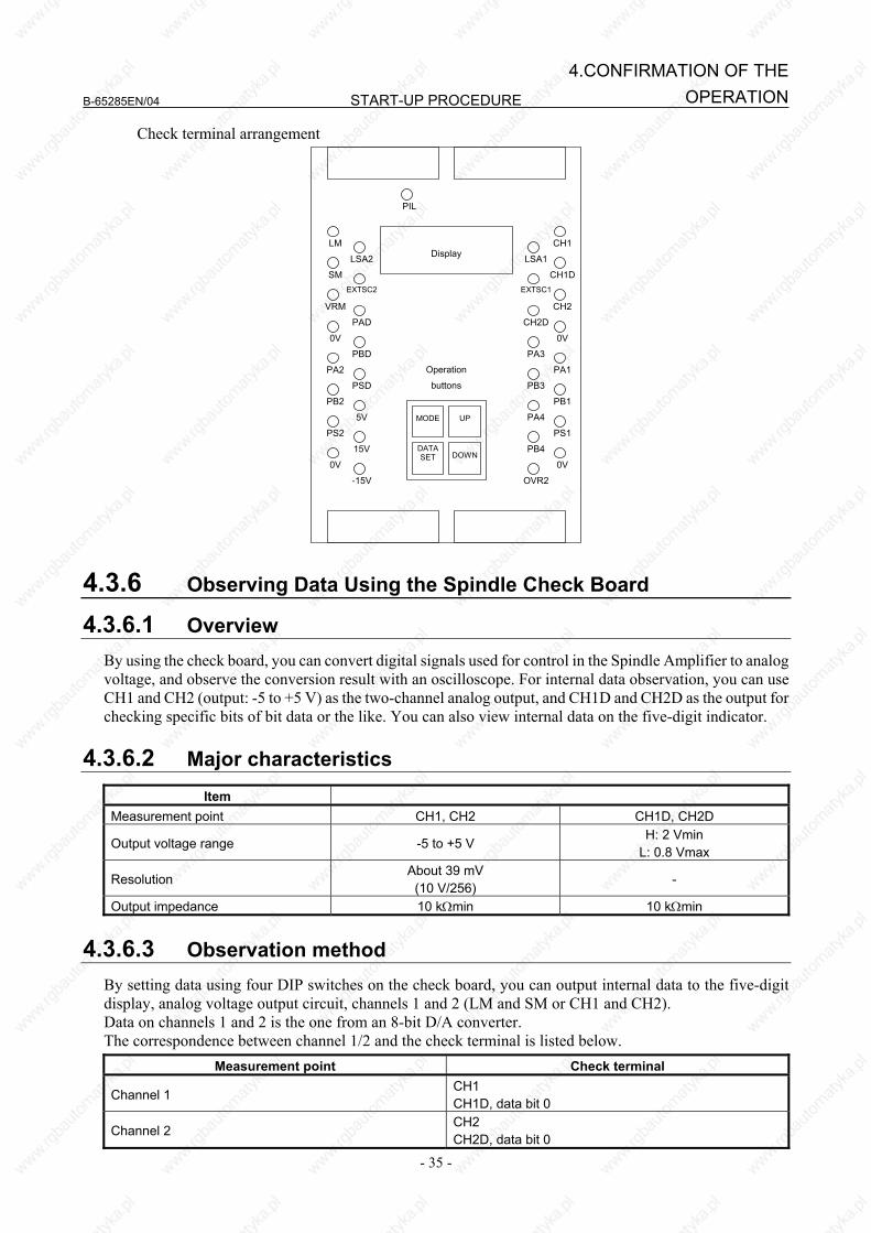
B-65285EN/04 START-UP PROCEDURE
- 35 -
4.CONFIRMATION OF THEOPERATION
Check terminal arrangement
LM
LSA2
SMEXTSC2
VRM
0V
PA2
PB2
PS2
0V
PAD
PBD
PSD
5V
15V
-15V
PIL
Operation
buttons
DisplayCH1
CH1D
CH2
0V
PA1
PB1
PS1
0V
LSA1
EXTSC1
CH2D
PA3
PB3
PA4
PB4
OVR2
DOWNDATASET
UPMODE
4.3.6 Observing Data Using the Spindle Check Board
4.3.6.1 Overview By using the check board, you can convert digital signals used for control in the Spindle Amplifier to analog voltage, and observe the conversion result with an oscilloscope. For internal data observation, you can use CH1 and CH2 (output: -5 to +5 V) as the two-channel analog output, and CH1D and CH2D as the output for checking specific bits of bit data or the like. You can also view internal data on the five-digit indicator.
4.3.6.2 Major characteristics Item
Measurement point CH1, CH2 CH1D, CH2D
Output voltage range -5 to +5 V H: 2 Vmin
L: 0.8 Vmax
Resolution About 39 mV
(10 V/256) -
Output impedance 10 kΩmin 10 kΩmin
4.3.6.3 Observation method By setting data using four DIP switches on the check board, you can output internal data to the five-digit display, analog voltage output circuit, channels 1 and 2 (LM and SM or CH1 and CH2). Data on channels 1 and 2 is the one from an 8-bit D/A converter. The correspondence between channel 1/2 and the check terminal is listed below.
Measurement point Check terminal
Channel 1 CH1 CH1D, data bit 0
Channel 2 CH2 CH2D, data bit 0
START-UP PROCEDURE B-65285EN/04
- 36 -
4.CONFIRMATION OF THE OPERATION
4.3.6.4 Specifying data to be monitored
<1> Press the four setting switches at the same time for at least a second ."FFFFF" will be displayed on the indicator.
<2> Turn off the switches and press the "MODE" switch. "d-00" will be displayed on the indicator and the system will enter the mode for monitoring internal data.
<3> In this mode, the motor can be operated normally. Press the "UP" or "DOWN" switch while holding down the "MODE" switch. The indicator display
will change in the range of "d-00" to "d-12". <4> The following shows the correspondence between the destinations of the internal data of the serial
spindle and addresses d-01 to d-12. d-01 to d-04 : Specifies the amount of data to be output to the indicator, data shift, and output format (decimal or hexadecimal). d-05 to d-08 : Specifies the amount of data to be output to the channel 1, data shift, and whether an offset is provided. d-09 to d-12 : Specifies the amount of data to be output to the channel 2, data shift, and whether an offset is provided.
<5> Select address d-xx in the procedure for setting data described in <3>. <6> Turn off the "MODE" switch. "d-xx" will disappear 0.5 second later, and the data will be displayed for
a second. Change the set data using the "UP" or "DOWN" switch within the second the data is displayed. <7> When more than a second elapses without pressing the "UP" or "DOWN" switch, data cannot be
changed. If the "MODE" switch is turned on or off, however, setting can be started from the beginning of the
step in item <6>.
4.3.6.5 Address descriptions and initial values (Spindle Amplifier) [Output to the indicator]
Address Description Initial value d-01 Specifies a data number. 0 d-02 Shift at data output (0 to 31 bits) 0
d-03 Data shift direction 0 : Data is shifted right. 1 : Data is shifted left.
0
d-04 Display format 0 : Decimal notation 1 : Hexadecimal notation(0 to F)
0
[Output to the channel 1]
Address Description Initial value
d-05 Specifies a data number 218
(U-phase current)
d-06 Shift at data output (0 to 31 bits)
8
d-07 Data shift direction
0: Data is shifted right 1: Data is shifted left
0
d-08 Offset
0: Not provided 1: Provided
1

B-65285EN/04 START-UP PROCEDURE
- 37 -
4.CONFIRMATION OF THEOPERATION
[Output to the channel 2] Address Description Initial value
d-09 Specifies a data number 19
(Motor velocity)
d-10 Shift at data output (0 to 31 bits)
18
d-11 Data shift direction
0: Data is shifted right 1: Data is shifted left
0
d-12 Offset
0: Not provided 1: Provided
1
4.3.6.6 Principles in outputting the internal data of the serial spindle
The length of data is 32 bits (BIT31 TO BIT00) unless it is described as 16 bits.
BIT31 BIT00BIT01BIT02BIT03……
(1) Example of output to the indicator
Example1: Displaying data in decimal When the number of digits to shift data (d-02)=0 and display format (d-04)=0 (decimal notation): The
last 16 bits of data (BIT15 to BIT00) are converted into decimal (0 to 65535 max.) and displayed.
BIT15 BIT00BIT01……
16 bitsConverted into decimaldata and displayed
X X X X XIndicator Example2: Displaying data in hexadecimal When the number of digits to shift data (d-02)=0 and display format (d-04)=1 (hexadecimal notation):
The last 16 bits of data (BIT15 to BIT00) are converted into hexadecimal (0 to FFFFF max.) and displayed.
BIT15 BIT00BIT01……
16 bitsConverted into hexadecimaldata and displayed
X X X XIndicator (The fifth digit is blank.)
Example3: Shifting data left When the number of digits to shift data (d-02)=3, the shift direction is left (d-03=1), and display format
(d-04)=1 (hexadecimal notation): Data in BIT12 to BIT00 and the last three bits of data (=0) are converted into hexadecimal (0 to FFFFF max.) and displayed.
BIT12 ……
16 bitsConverted into hexadecimaldata and displayed
X X X XIndicator (The fifth digit is blank.)
000BIT00BIT01
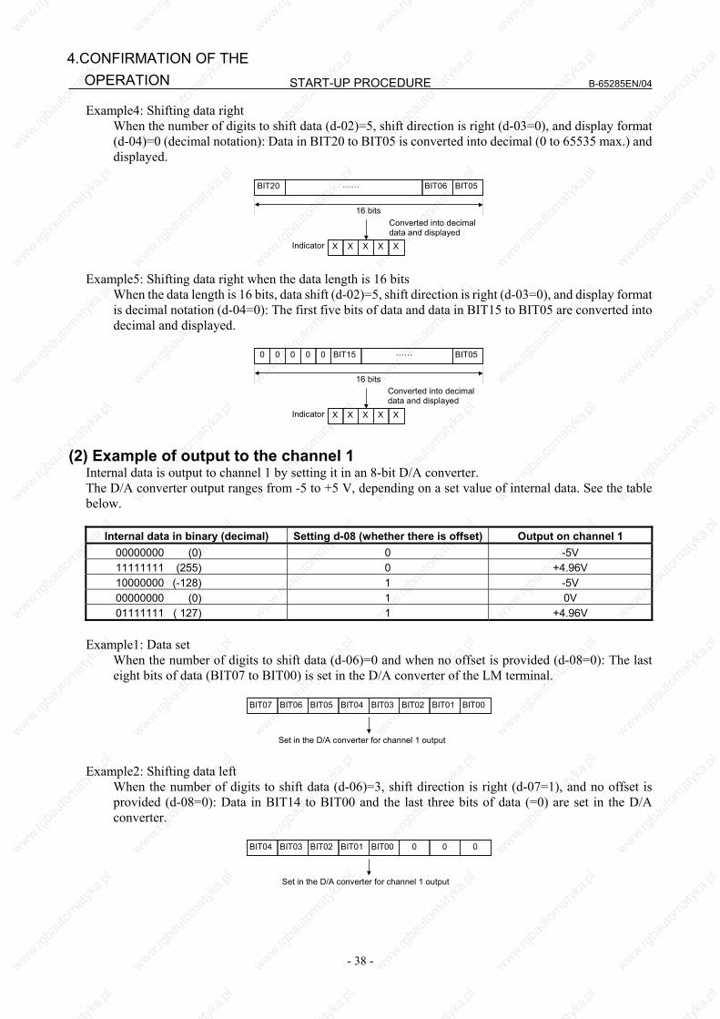
START-UP PROCEDURE B-65285EN/04
- 38 -
4.CONFIRMATION OF THE OPERATION
Example4: Shifting data right When the number of digits to shift data (d-02)=5, shift direction is right (d-03=0), and display format
(d-04)=0 (decimal notation): Data in BIT20 to BIT05 is converted into decimal (0 to 65535 max.) and displayed.
BIT20 BIT05BIT06……
16 bitsConverted into decimaldata and displayed
X X X X XIndicator Example5: Shifting data right when the data length is 16 bits When the data length is 16 bits, data shift (d-02)=5, shift direction is right (d-03=0), and display format
is decimal notation (d-04=0): The first five bits of data and data in BIT15 to BIT05 are converted into decimal and displayed.
BIT15 ……
16 bitsConverted into decimaldata and displayed
X X X X XIndicator
000 BIT050 0
(2) Example of output to the channel 1
Internal data is output to channel 1 by setting it in an 8-bit D/A converter. The D/A converter output ranges from -5 to +5 V, depending on a set value of internal data. See the table below.
Internal data in binary (decimal) Setting d-08 (whether there is offset) Output on channel 1 00000000 (0) 0 -5V 11111111 (255) 0 +4.96V 10000000 (-128) 1 -5V 00000000 (0) 1 0V 01111111 ( 127) 1 +4.96V
Example1: Data set When the number of digits to shift data (d-06)=0 and when no offset is provided (d-08=0): The last
eight bits of data (BIT07 to BIT00) is set in the D/A converter of the LM terminal.
BIT07 BIT00BIT01
Set in the D/A converter for channel 1 output
BIT06 BIT05 BIT04 BIT03 BIT02
Example2: Shifting data left When the number of digits to shift data (d-06)=3, shift direction is right (d-07=1), and no offset is
provided (d-08=0): Data in BIT14 to BIT00 and the last three bits of data (=0) are set in the D/A converter.
BIT04 00
Set in the D/A converter for channel 1 output
BIT03 BIT02 BIT01 BIT00 0
B-65285EN/04 START-UP PROCEDURE
- 39 -
4.CONFIRMATION OF THEOPERATION
Example3: Shifting data right When the number of digits to shift data (d-06)=10, shift direction is right (d-07=1), and no offset is
provided (d-08=0): Data in BIT17 to BIT10 is set in the D/A converter.
BIT17 BIT10BIT11
Set in the D/A converter for channel 1 output
BIT16 BIT15 BIT14 BIT13 BIT12
Example4: Shifting data right when the data length is 16 bits When the data length is 16 bits, data shift (d-06)=10, shift direction is right (d-07=0), and no offset is
provided (d-08=0): The first two bits of data (=0) and data in BIT15 to BIT10 are set in the D/A converter.
0 BIT10BIT11
Set in the D/A converter for channel 1 output
0 BIT15 BIT14 BIT13 BIT12
Example5: If an offset is provided When the number of digits to shift data (d-06)=10, shift direction is right (d-07=0), and an offset is
provided (d-08=1): Data in most significant bit BIT17 (to which 1 is added) and data in BIT16 to BIT10 are set in the D/A converter.
Set in the D/A converter for channel 1 output
BIT17 Data +1 BIT10BIT11BIT16 BIT15 BIT14 BIT13 BIT12
Example6: Data bit observation For data shift (d-06) = 0 with no offset (d-08 = 0), the lowest data bit (BIT00) can be observed as a
high/low level at check terminal CH1D.
BIT07 BIT00BIT01
Output to check terminal CH1D
BIT06 BIT05 BIT04 BIT03 BIT02
(3) Example of output to the channel 2 Output to the channel 2 is the same as that to the channel 1. However, the addresses for setting data (d-09 to d-12) are different from those for output to the channel 1. Setting velocity information in the channel 1 and the number of errors in the channel 2 enables simultaneous monitoring of the change in each data item using the two channels.
4.3.6.7 Data numbers
(1) Data numbers Data No. Description Data
length Remarks
Main data 16 Motor speed command 32 The 12th bit (BIT12) indicates a units in min-1.
19 Motor speed 32 The 12th bit (BIT12) indicates a units in min-1. (An estimated value is used for the αCi series.)
25 Motor speed deviation 32 (Speed command - motor speed) The 12th bit (BIT12) indicates a units in min-1.
4 Move command 32 Number of command pulses for ITP (usually 8 ms)
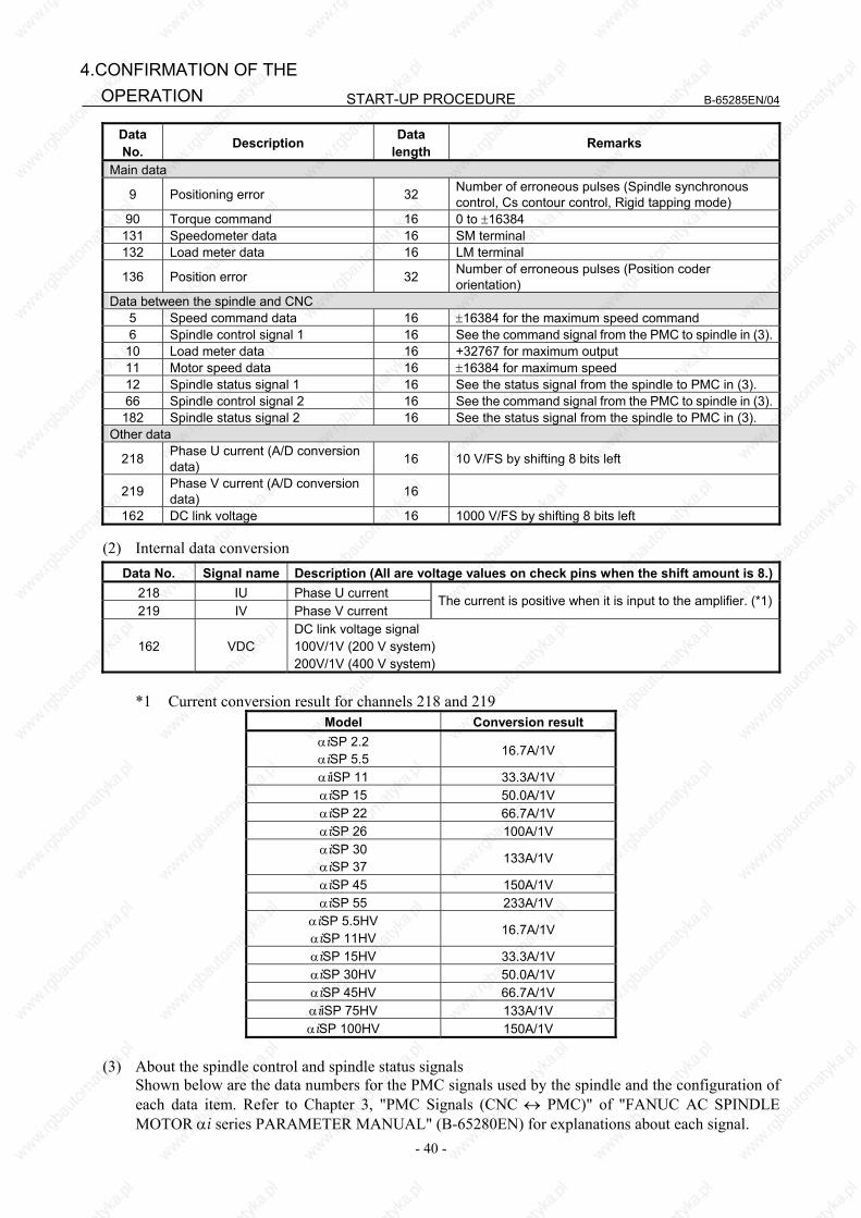
START-UP PROCEDURE B-65285EN/04
- 40 -
4.CONFIRMATION OF THE OPERATION
Data No. Description Data
length Remarks
Main data
9 Positioning error 32 Number of erroneous pulses (Spindle synchronous control, Cs contour control, Rigid tapping mode)
90 Torque command 16 0 to ±16384 131 Speedometer data 16 SM terminal 132 Load meter data 16 LM terminal
136 Position error 32 Number of erroneous pulses (Position coder orientation)
Data between the spindle and CNC 5 Speed command data 16 ±16384 for the maximum speed command 6 Spindle control signal 1 16 See the command signal from the PMC to spindle in (3).
10 Load meter data 16 +32767 for maximum output 11 Motor speed data 16 ±16384 for maximum speed 12 Spindle status signal 1 16 See the status signal from the spindle to PMC in (3). 66 Spindle control signal 2 16 See the command signal from the PMC to spindle in (3).182 Spindle status signal 2 16 See the status signal from the spindle to PMC in (3).
Other data
218 Phase U current (A/D conversion data) 16 10 V/FS by shifting 8 bits left
219 Phase V current (A/D conversion data) 16
162 DC link voltage 16 1000 V/FS by shifting 8 bits left (2) Internal data conversion
Data No. Signal name Description (All are voltage values on check pins when the shift amount is 8.)218 IU Phase U current 219 IV Phase V current
The current is positive when it is input to the amplifier. (*1)
162 VDC DC link voltage signal 100V/1V (200 V system) 200V/1V (400 V system)
*1 Current conversion result for channels 218 and 219
Model Conversion result αiSP 2.2 αiSP 5.5 16.7A/1V
αiiSP 11 33.3A/1V αiSP 15 50.0A/1V αiSP 22 66.7A/1V αiSP 26 100A/1V αiSP 30 αiSP 37 133A/1V
αiSP 45 150A/1V αiSP 55 233A/1V
αiSP 5.5HV αiSP 11HV 16.7A/1V
αiSP 15HV 33.3A/1V αiSP 30HV 50.0A/1V αiSP 45HV 66.7A/1V αiiSP 75HV 133A/1V αiSP 100HV 150A/1V
(3) About the spindle control and spindle status signals Shown below are the data numbers for the PMC signals used by the spindle and the configuration of
each data item. Refer to Chapter 3, "PMC Signals (CNC ↔ PMC)" of "FANUC AC SPINDLE MOTOR αi series PARAMETER MANUAL" (B-65280EN) for explanations about each signal.

B-65285EN/04 START-UP PROCEDURE
- 41 -
4.CONFIRMATION OF THEOPERATION
(a) Data number 6 : Spindle control signal 1 #15 #14 #13 #12 #11 #10 #9 #8 RCH RSL INTG SOCN MCFN SPSL *ESP ARST #7 #6 #5 #4 #3 #2 #1 #0
MRDY ORCM SFR SRV CTH1 CTH2 TLMH TLML
(b) Data number 66 : Spindle control signal 2 #15 #14 #13 #12 #11 #10 #9 #8
DSCN SORSL MPOF #7 #6 #5 #4 #3 #2 #1 #0
RCHHG MFNHG INCMD OVR NRRO ROTA INDX
(c) Data number 12 : Spindle status signal 1 #15 #14 #13 #12 #11 #10 #9 #8
RCFN RCHP CFIN CHP #7 #6 #5 #4 #3 #2 #1 #0
ORAR TLM LDT2 LDT1 SAR SDT SST ALM
(d) Data number 182 : Spindle status signal 2 #15 #14 #13 #12 #11 #10 #9 #8
#7 #6 #5 #4 #3 #2 #1 #0
EXOF SOREN INCST PC1DT
4.3.6.8 Example of observing data
(1) Example of observing a positioning error using the channel 1 Address Description Set Data
d-05 Data number 9 9 9 9 d-06 Data shift 0 1 1 2 d-07 Data shift direction 0 1 1 1 d-08 Offset 1 1 1 1
Data unit (NOTE) 256p/FS 512p/FS 128p/FS 64p/FS
NOTE FS=10V (-5V to 5V)
(2) Example of observing a motor speed using the channel 2
Address Description Set Data d-09 Data number 19 19 19 d-10 Data shift 12 13 11 d-11 Data shift direction 0 0 0 d-12 Offset 0 0 0
Data unit (NOTE) 256min-1/FS 512min-1/FS 128 min-1/FS
NOTE FS=10V (-5V to 5V)
START-UP PROCEDURE B-65285EN/04
- 42 -
4.CONFIRMATION OF THE OPERATION
(3) Observation of phase U current in the αiSP 11
Data No. 218Shift amount 8Shift direction 0 (shifted left)Offset 1 (provided)
Setting of observation data+5 V
0 V
-5 V
100 A
33.3 A/1 V
4.3.7 Checking Parameters Using the Spindle Check Board
4.3.7.1 Overview By using the check board, you can check parameter values transferred to the Spindle Amplifier. Specify parameter numbers using the four setting switches on the check board, and check parameter values on the five-digit indicator.
4.3.7.2 Checking parameters <1> Press the four setting switches at the same time for at least one second. "FFFFF" will be displayed on
the indicator. <2> Turn off the switches and press the "MODE" switch. "d-00" will be displayed on the indicator and the
system will enter the mode for measuring internal data. <3> With "0" set for "d-00", press the "MODE" and "DATA SET" switches at the same time for at least one
second. "CCCCC" will be displayed on the indicator. <4> Turn off the switches and press the "MODE" switch. "F-xxx" will be displayed on the indicator and the
system will enter the mode for checking spindle parameters (F-mode). (Even in this mode, the motor can be operated normally.)
<5> Press the "UP" or "DOWN" switch while holding down the "MODE" switch (with "F-xxx" displayed). The number of "F-xxx" increases or decreases. Set the internal number of a parameter you want to check. For correspondences between the parameter internal numbers and NC parameter numbers, see the parameter list in the appendix to the parameter manual.
<6> Turn off the switches. The parameter value corresponding to the set internal number is displayed for about one second. (Bit parameter values are displayed in hexadecimal.)
4.3.8 Observing Data Using the SERVO GUIDE
4.3.8.1 Overview Using the servo adjustment tool, SERVO GUIDE, enables you to observe internal data for the spindle. This subsection describes the spindle data that can be observed using the SERVO GUIDE. It also presents examples of observed data. Refer to online help for detailed explanations about how to use the SERVO GUIDE.
4.3.8.2 Usable series and editions Series 9D50/B(02) and subsequent editions Series 9D53/A(01) and subsequent editions Series 9D70/A(01) and subsequent editions Series 9D80/A(01) and subsequent editions Series 9D90/A(01) and subsequent editions Series 9DA0/A(01) and subsequent editions
B-65285EN/04 START-UP PROCEDURE
- 43 -
4.CONFIRMATION OF THEOPERATION
4.3.8.3 List of spindle data that can be observed using the SERVO
GUIDE The following table lists the spindle data that can be observed using the SERVO GUIDE.
Data type Description SPEED Motor speed INORM Motor current amplitude TCMD Torque command VCMD Motor speed command VERR Speed deviation ERR Position error (9D50/11 and subsequent editions *1)
ERRC Position error (CNC) ORERR Position error at orientation WMDAT Move command for an individual position loop SYNC Synchronization error (9D50/11 and subsequent editions *1)
PCPOS Cumulative position feedback value MCMD Move command for an individual communication cycle ERR2 Position error 2
ERR2C Position error 2(CNC) (9D50/11 and subsequent editions *1)CSPOS Cumulative position feedback value SPCMD Speed command data from the CNC SPSPD Spindle speed (9D50/11 and subsequent editions *1)SPCT1 Spindle control signal 1 SPCT2 Spindle control signal 2 SPCT3 Spindle control signal 3 (9D50/11 and subsequent editions *1)SPST1 Spindle status signal 1 SPST2 Spindle status signal 2 ORSEQ Orientation sequence data SFLG1 Spindle flag 1 (9D50/11 and subsequent editions *1)SPPOS Spindle position data (9D50/12 and subsequent editions *2)LMDAT Load meter data 1 (9D50/11 and subsequent editions *1)DTRQ Spindle load torque (Unexpected disturbance torque detection function) 1
(9D50/11 and subsequent editions *1)FREQ Frequency of disturbance torque (Disturbance input function) 1
(9D50/11 and subsequent editions *1)GAIN Gain data (Disturbance input function) 1 (9D50/11 and subsequent editions *1)
MTTMP Motor winding temperature 1 (9D50/11 and subsequent editions *1)MFBDF Motor sensor feedback incremental data 1 (9D50/11 and subsequent editions *1)
(For amplitude ratio and phase difference compensation) SFBDF Spindle sensor feedback incremental data 1 (9D50/11 and subsequent editions *1)
(For amplitude ratio and phase difference compensation) PA1 AD data 1 of A phase of motor sensor (9D50/11 and subsequent editions *1)PB1 AD data 1 of B phase of motor sensor (9D50/11 and subsequent editions *1)PA2 AD data 1 of A phase of spindle sensor (9D50/11 and subsequent editions *1)PB2 AD data 1 of B phase of spindle sensor (9D50/11 and subsequent editions *1)VDC DC link voltage 1 (9D50/11 and subsequent editions *1)
SFERR Semi-full error 1 (Dual position feedback) (9D50/11 and subsequent editions *1)SMERR Semi-closed side error 1 (Dual position feedback) (9D50/11 and subsequent editions *1)SPACC Spindle acceleration data 1 (9D50/20 and subsequent editions *4)

START-UP PROCEDURE B-65285EN/04
- 44 -
4.CONFIRMATION OF THE OPERATION
NOTE *1 Available with 9D53/03 and subsequent editions for series 9D53, 9D70/02 and
subsequent editions for series 9D70, 9D80/01 and subsequent editions for series 9D80, and 9D90/01 and subsequent editions for series 9D90.
*2 Available with 9D53/04 and subsequent editions for series 9D53, 9D70/03and subsequent editions for series 9D70, 9D80/01and subsequent editions for series 9D80, and 9D90/0 and subsequent editions for series 9D90.
*3 To observe data marked with *1 and *2, the SERVO GUIDE Ver. 3.0 or later is required.
*4 Available with 9D70/10 and subsequent editions for series 9D70, 9D80/04 and subsequent editions for series 9D80, and 9D90/01 and subsequent editions for series 9D90.
To observe this data, the SERVO GUIDE Ver. 4.10 or later is required.
4.3.8.4 About the spindle control and spindle status signals As stated in the previous item, the SERVO GUIDE can be used to observe the PMC signals (spindle control signals 1 and 2 and spindle status signals 1 and 2) used by the spindle. Listed below is the data configuration for spindle control signals 1 and 2 and spindle status signals 1 and 2. Refer to Chapter 3, "PMC Signals (CNC ↔ PMC)" of "FANUC AC SPINDLE MOTOR αi series PARAMETER MANUAL" (B-65280EN) for explanations about each signal. (a) Spindle control signal 1 (SPCT1)
#15 #14 #13 #12 #11 #10 #9 #8 RCH RSL INTG SOCN MCFN SPSL *ESP ARST #7 #6 #5 #4 #3 #2 #1 #0
MRDY ORCM SFR SRV CTH1 CTH2 TLMH TLML
(b) Spindle control signal 2 (SPCT2)
#15 #14 #13 #12 #11 #10 #9 #8 DSCN SORSL MPOF
#7 #6 #5 #4 #3 #2 #1 #0 RCHHG MFNHG INCMD OVR NRRO ROTA INDX
(c) Spindle control signal 3 (SPCT3)
#15 #14 #13 #12 #11 #10 #9 #8
#7 #6 #5 #4 #3 #2 #1 #0
(d) Spindle status signal 1 (SPST1)
#15 #14 #13 #12 #11 #10 #9 #8 RCFN RCHP CFIN CHP
#7 #6 #5 #4 #3 #2 #1 #0 ORAR TLM LDT2 LDT1 SAR SDT SST ALM
(e) Spindle status signal 2 (SPST2)
#15 #14 #13 #12 #11 #10 #9 #8
#7 #6 #5 #4 #3 #2 #1 #0 EXOF SOREN INCST PC1DT
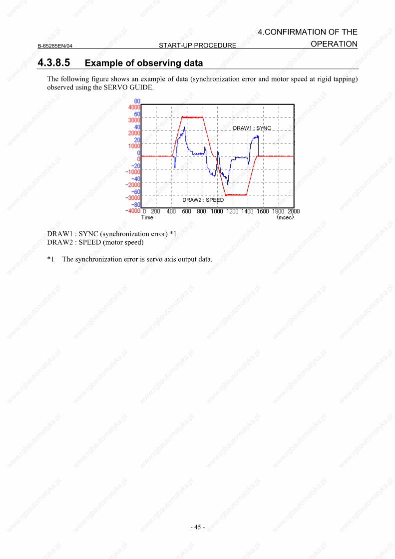
B-65285EN/04 START-UP PROCEDURE
- 45 -
4.CONFIRMATION OF THEOPERATION
4.3.8.5 Example of observing data The following figure shows an example of data (synchronization error and motor speed at rigid tapping) observed using the SERVO GUIDE.
DRAW2 : SPEED
DRAW1 : SYNC
DRAW1 : SYNC (synchronization error) *1 DRAW2 : SPEED (motor speed) *1 The synchronization error is servo axis output data.


II. TROUBLESHOOTING

B-65285EN/04 TROUBLESHOOTING 1.OVERVIEW
- 49 -
1 OVERVIEW This part describes the troubleshooting procedure for each amplifier. Read the section related to your current trouble to locate it and take an appropriate action. First, check the alarm number and STATUS display indicated on your amplifier with each list (alarm numbers in the list are those for the CNC) in Chapter 2 to find the corresponding detailed information in Chapter 3. Then take an appropriate action according to the detailed information.

TROUBLESHOOTING B-65285EN/04
- 50 -
2.ALARM NUMBERS AND BRIEF DESCRIPTIONS
2 ALARM NUMBERS AND BRIEF DESCRIPTIONS
2.1 FOR Series 15i
2.1.1 Servo Alarm
Alarm No. SV PS Description Remarks SV0027 Invalid digital servo parameter setting 3.3.6 SV0361 Pulsecoder phase error (built-in) 3.3.7 (1) SV0364 Soft phase alarm (built-in) 3.3.7 (1) SV0365 LED error (built-in) 3.3.7 (1) SV0366 Pulse error (built-in) 3.3.7 (1) SV0367 Count error (built-in) 3.3.7 (1) SV0368 Serial data error (built-in) 3.3.7 (3) SV0369 Data transfer error (built-in) 3.3.7 (3) SV0380 LED error (separate) 3.3.7 (2) SV0381 Pulsecoder phase error (separate) 3.3.7 (2) SV0382 Count error (separate) 3.3.7 (2) SV0383 Pulse error (separate) 3.3.7 (2) SV0384 Soft phase alarm (separate) 3.3.7 (2) SV0385 Serial data error (separate) 3.3.7 (3) SV0386 Data transfer error (separate) 3.3.7 (3) SV0387 Sensor error (separate) 3.3.7 (2) SV0421 Excessive semi-full error 3.3.8 SV0430 Servo motor overheat 3.3.5 SV0431 3 Converter: main circuit overload 3.1.3 SV0432 6 Converter: control power supply undervoltage 3.1.6 SV0433 4 Converter: DC link undervoltage 3.1.4 SV0434 2 Inverter: control power supply undervoltage 3.2 SV0435 5 Inverter: DC link undervoltage 3.2 SV0436 Soft thermal (OVC) 3.3.3 SV0437 1 Converter: input circuit overcurrent 3.1.1 SV0438 b Inverter: motor current alarm (L axis) 3.2 SV0438 c Inverter: motor current alarm (M axis) 3.2 SV0438 d Inverter: motor current alarm (N axis) 3.2 SV0439 7 Converter: DC link overvoltage 3.1.7 SV0440 H Converter: Excessive deceleration power 3.1.11 SV0441 Current offset error 3.3.8 SV0442 5 Converter: DC link precharge failure 3.1.5 SV0443 2 Converter: cooling fan stopped 3.1.2 SV0444 1 Inverter: internal cooling fan stopped 3.2 SV0445 Soft disconnection alarm 3.3.4 SV0446 Hard disconnection alarm Not issued SV0447 Hard disconnection alarm (separate) 3.3.4 SV0448 Feedback mismatch alarm 3.3.8 SV0449 8. Inverter: IPM alarm (L axis) 3.2 SV0449 9. Inverter: IPM alarm (M axis) 3.2 SV0449 A. Inverter: IPM alarm (N axis) 3.2 SV0600 8 Inverter: DC link current alarm (L axis) 3.2 SV0600 9 Inverter: DC link current alarm (M axis) 3.2
B-65285EN/04 TROUBLESHOOTING
- 51 -
2.ALARM NUMBERS ANDBRIEF DESCRIPTIONS
Alarm No. SV PS Description Remarks SV0600 A Inverter: DC link current alarm (N axis) 3.2 SV0601 F Inverter: cooling fan stopped of the radiator 3.2 SV0602 6 Inverter: overheat 3.2 SV0603 8. Inverter: IPM alarm (OH) (L axis) 3.2 SV0603 9. Inverter: IPM alarm (OH) (M axis) 3.2 SV0603 A. Inverter: IPM alarm (OH) (N axis) 3.2 SV0604 P Communication error between amplifiers 3.2 SV0605 8 Converter: Excessive regenerative power 3.1.8 SV0606 A Converter: cooling fan stopped of the radiator 3.1.9 SV0607 E Open phase in the converter main power supply 3.1.10
2.1.2 Spindle Alarm
Alarm No. SP PS Description RemarksSP0001 01 Motor overheat 3.4.1 SP0002 02 Excessive speed deviation 3.4.2 SP0003 03 DC link fuse blown 3.4.3 SP0004 04 E Open phase in the converter main power supply 3.1.10 SP0006 06 Temperature sensor disconnected 3.4.4 SP0007 07 Excessive speed 3.4.5 SP0009 09 Main circuit overload/IPM overheat 3.4.6 SP0010 10 Low power supply input voltage 3.4.7 SP0011 11 7 Converter: DC link overvoltage 3.1.7
SP0012 12 DC link overcurrent/IPM alarm 3.4.8 3.5.1
SP098x 13 CPU internal data memory error 3.4.9 SP0014 14 Amplifier ID not registered 3.4.10 SP0015 15 Output switching/spindle switching alarm 3.4.11 SP0017 17 Amplifier ID data error 3.4.13 SP098x 18 Program sum check error 3.4.14 SP098x 19 Excessive offset of the phase U current detection circuit 3.4.15 SP098x 20 Excessive offset of the phase V current detection circuit 3.4.15 SP0021 21 Position sensor polarity setting incorrect 3.4.16 SP0022 22 Spindle amplifier current overload 3.4.17 SP022x 24 Serial transfer data error 3.4.18 SP0027 27 Position coder disconnected 3.4.19 SP0029 29 Short-period overload 3.4.20 SP0030 30 1 Overcurrent in the converter input circuit 3.1.1 SP0031 31 Motor lock alarm 3.4.21 SP0032 32 Serial communication LSI RAM error 3.4.22 SP0033 33 5 Converter: DC link precharge failure 3.1.5 SP0034 34 Parameter data out of the specifiable range 3.4.23 SP0035 35 Gear ratio parameter error 3.5.2 SP0036 36 Error counter overflow 3.4.24 SP0037 37 Speed detector parameter error 3.4.25 SP0041 41 Position coder one-rotation signal detection error 3.4.26 SP0042 42 Position coder one-rotation signal not detected 3.4.27 SP0043 43 Position coder signal for differential speed mode disconnected 3.4.28
SP0046 46 Position sensor one-rotation signal detection error during thread cutting
3.4.29
SP0047 47 Position coder signal error 3.4.30
SP0049 49 Overflow of converted motor speed for differential spindle speed
control 3.4.31
TROUBLESHOOTING B-65285EN/04
- 52 -
2.ALARM NUMBERS AND BRIEF DESCRIPTIONS
Alarm No. SP PS Description Remarks
SP0050 50 Excessive speed command calculation value during spindle synchronization
3.1.4
SP0051 51 4 Converter: DC link undervoltage 3.4.33 SP0052 52 ITP signal error I 3.4.33 SP0053 53 ITP signal error II 3.4.34 SP0054 54 Current overload alarm 3.4.35 SP0055 55 Abnormal switching status of power leads 3.4.36 SP0056 56 Internal cooling fan stopped 3.1.11 SP0057 57 H Converter: excessive deceleration power 3.1.3 SP0058 58 3 Converter: main circuit overload 3.1.2 SP0059 59 2 Converter: cooling fan stopped 3.4.37 SP0061 61 Excessive semi-closed loop/closed loop position error alarm 3.4.38 SP0065 65 Abnormal travel distance in magnetic pole determination operation 3.4.39 SP0066 66 Communication alarm between spindle and amplifier 3.4.45 SP0069 69 Safety speed exceeded 3.4.46 SP0070 70 Abnormal axis data 3.4.47 SP0071 71 Abnormal safety parameter 3.4.51 SP0072 72 Motor speed mismatch 3.4.52 SP0073 73 Motor sensor disconnected 3.4.53 SP0074 74 CPU test alarm 3.4.54 SP0075 75 CRC test alarm 3.4.55 SP0076 76 Safety function not executed 3.4.56 SP0077 77 Axis number mismatch 3.4.57 SP0078 78 Safety parameter mismatch 3.4.58 SP0079 79 Abnormal initial test operation 3.4.59 SP0080 80 Destination amplifier error in inter-spindle amplifier communication 3.4.60 SP0081 81 Motor sensor one-rotation signal detection error 3.4.61 SP0082 82 Motor sensor one-rotation signal not detected 3.4.62 SP0083 83 Motor sensor signal error 3.4.63 SP0084 84 Spindle sensor disconnected 3.4.64 SP0085 85 Spindle sensor one-rotation signal detection error 3.4.83 SP0086 86 Spindle sensor one-rotation signal not detected 3.4.83 SP0087 87 Spindle sensor signal error 3.4.65 SP0088 88 Cooling fan stopped of the radiator 3.4.65 SP0089 89 Sub module SM (SSM) error 3.4.65 SP0090 90 Unexpected rotation alarm 3.4.66 SP0091 91 Pole position count miss alarm 3.1.6 SP0092 92 Velocity command-dependent overspeed alarm 3.1.8 SP0097 (MODEL A) Other spindle amplifier alarm
3.1.9
SP0097x A Program ROM error 3.4.67 SP0097x A1 Program ROM error 3.4.67 SP0097x A2 Program ROM error 3.4.67 SP0098 Other converter alarm 3.4.68 SP0098 (MODEL A)
b0 Communication error between amplifiers 3.4.74
SP0098 (MODEL A)
b1 6 Converter: control power supply low voltage 3.4.76
SP0098 (MODEL A)
b2 8 Converter: excessive regenerative power 3.4.77
SP0098 (MODEL A)
b3 2 Converter: cooling fan stopped of the radiator 3.4.78
SP0110 (MODEL B)
b0 Communication error between amplifiers 3.4.79

B-65285EN/04 TROUBLESHOOTING
- 53 -
2.ALARM NUMBERS ANDBRIEF DESCRIPTIONS
Alarm No. SP PS Description RemarksSP0111 (MODEL B)
b1 6 Converter: control power supply low voltage 3.4.80
SP0112 (MODEL B)
b2 8 Converter: excessive regenerative power 3.4.81
SP0113 (MODEL B)
b3 A Converter: cooling fan stopped of the radiator 3.4.82
SP0120 (MODEL B)
C0 Communication data alarm 3.4.51
SP0121 (MODEL B)
C1 Communication data alarm 3.4.51
SP0122 (MODEL B)
C2 Communication data alarm 3.4.51
SP0123 (MODEL B)
C3 Spindle switching circuit error 3.4.52
SP0130 d0 Speed polarity error in torque tandem operation 3.4.74 SP0132 d2 Serial data error 3.4.76 SP0133 d3 Data transfer error 3.4.77 SP0134 d4 Soft phase alarm 3.4.78 SP0137 d7 Device communication error 3.4.79 SP0139 d9 Pulse error alarm 3.4.80 SP0140 E0 Count error alarm 3.4.81 SP0141 E1 Serial sensor one-rotation signal not detected 3.4.82
TROUBLESHOOTING B-65285EN/04
- 54 -
2.ALARM NUMBERS AND BRIEF DESCRIPTIONS
2.2 FOR Series 16i, 18i, 20i, 21i, 0i, AND Power Mate i
2.2.1 Servo Alarm
Alarm No. SV PS Description Remarks 361 Pulsecoder phase error (built-in) 3.3.7 (1) 364 Soft phase alarm (built-in) 3.3.7 (1) 365 LED error (built-in) 3.3.7 (1) 366 Pulse error (built-in) 3.3.7 (1) 367 Count error (built-in) 3.3.7 (1) 368 Serial data error (built-in) 3.3.7 (3) 369 Data transfer error (built-in) 3.3.7 (3) 380 LED error (separate) 3.3.7 (2) 381 Pulsecoder phase error (separate) 3.3.7 (2) 382 Count error (separate) 3.3.7 (2) 383 Pulse error (separate) 3.3.7 (2) 384 Soft phase alarm (separate) 3.3.7 (2) 385 Serial data error (separate) 3.3.7 (3) 386 Data transfer error (separate) 3.3.7 (3) 387 Sensor error (separate) 3.3.7 (2) 417 Invalid parameter 3.3.6 421 Excessive semi-full error 3.3.8 430 Servomotor overheat 3.3.5 431 3 Converter: main circuit overload 3.1.3 432 6 Converter: control undervoltage 3.1.6 433 4 Converter: DC link undervoltage 3.1.4 434 2 Inverter: control power supply undervoltage 3.2 435 5 Inverter: DC link undervoltage 3.2 436 Soft thermal (OVC) 3.3.3 437 1 Converter: input circuit overcurrent 3.1.1 438 b Inverter: motor current alarm (L axis) 3.2 438 c Inverter: motor current alarm (M axis) 3.2 438 d Inverter: motor current alarm (N axis) 3.2 439 7 Converter: DC link overvoltage 3.1.7 440 H Converter: excessive deceleration power 2.1.11 441 Current offset error 3.3.8 442 5 Converter: DC link precharge failure 3.1.5 443 2 Converter: cooling fan stopped 3.1.2 444 1 Inverter: internal cooling fan stopped 3.2 445 Soft disconnection alarm 3.3.4 447 Hard disconnection alarm (separate) 3.3.4 448 Feedback mismatch alarm 3.3.8 449 8. Inverter: IPM alarm (L axis) 3.2 449 9. Inverter: IPM alarm (M axis) 3.2 449 A. Inverter: IPM alarm (N axis) 3.2 453 Soft disconnection alarm (α Pulsecoder) 3.3.4 600 8. Inverter: DC link current alarm (L axis) 3.2 600 9. Inverter: DC link current alarm (M axis) 3.2 600 A. Inverter: DC link current alarm (N axis) 3.2 601 F Inverter: cooling fan stopped of the radiator 3.2 602 6 Inverter: overheat 3.2 603 8. Inverter: IPM alarm (OH) (L axis) 3.2 603 9. Inverter: IPM alarm (OH) (M axis) 3.2 603 A. Inverter: IPM alarm (OH) (N axis) 3.2
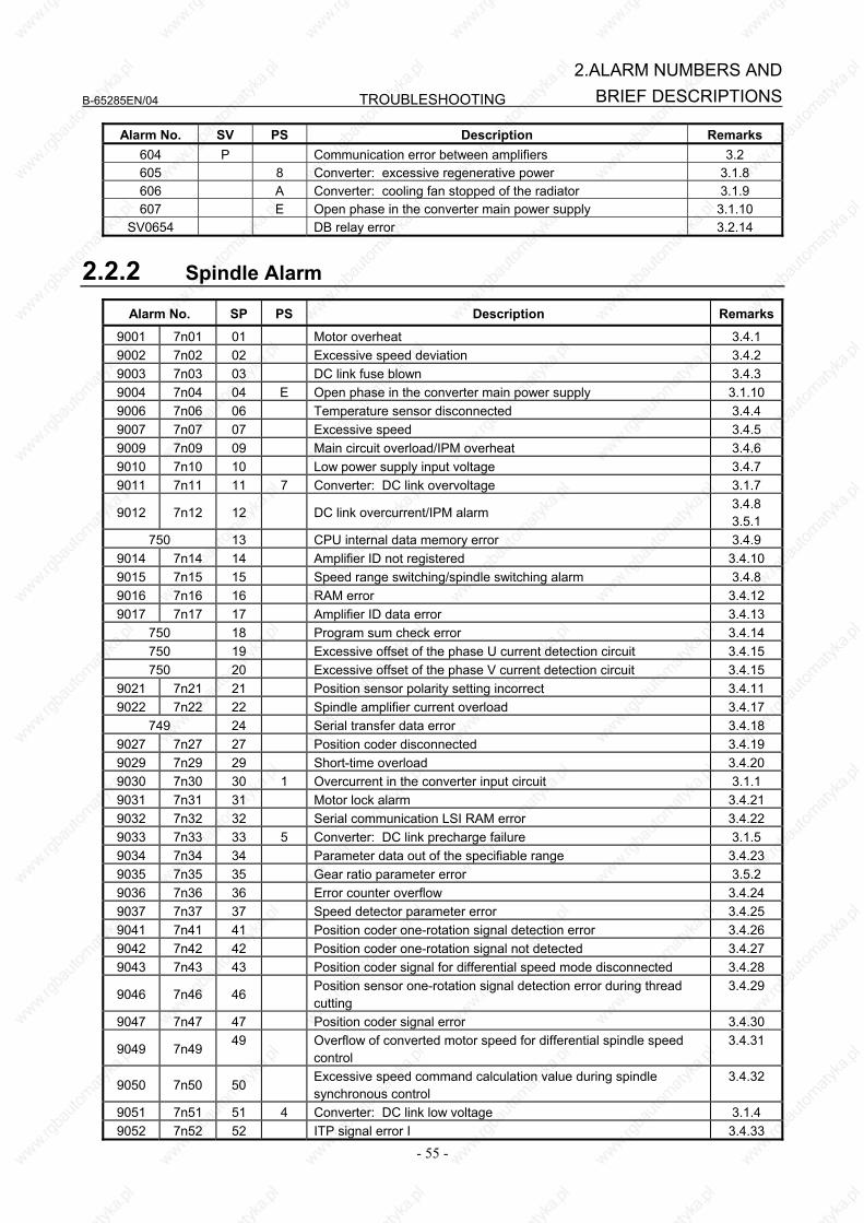
B-65285EN/04 TROUBLESHOOTING
- 55 -
2.ALARM NUMBERS ANDBRIEF DESCRIPTIONS
Alarm No. SV PS Description Remarks 604 P Communication error between amplifiers 3.2 605 8 Converter: excessive regenerative power 3.1.8 606 A Converter: cooling fan stopped of the radiator 3.1.9 607 E Open phase in the converter main power supply 3.1.10
SV0654 DB relay error 3.2.14
2.2.2 Spindle Alarm
Alarm No. SP PS Description Remarks
9001 7n01 01 Motor overheat 3.4.1 9002 7n02 02 Excessive speed deviation 3.4.2 9003 7n03 03 DC link fuse blown 3.4.3 9004 7n04 04 E Open phase in the converter main power supply 3.1.10 9006 7n06 06 Temperature sensor disconnected 3.4.4 9007 7n07 07 Excessive speed 3.4.5 9009 7n09 09 Main circuit overload/IPM overheat 3.4.6 9010 7n10 10 Low power supply input voltage 3.4.7 9011 7n11 11 7 Converter: DC link overvoltage 3.1.7
9012 7n12 12 DC link overcurrent/IPM alarm 3.4.8 3.5.1
750 13 CPU internal data memory error 3.4.9 9014 7n14 14 Amplifier ID not registered 3.4.10 9015 7n15 15 Speed range switching/spindle switching alarm 3.4.8 9016 7n16 16 RAM error 3.4.12 9017 7n17 17 Amplifier ID data error 3.4.13
750 18 Program sum check error 3.4.14 750 19 Excessive offset of the phase U current detection circuit 3.4.15 750 20 Excessive offset of the phase V current detection circuit 3.4.15
9021 7n21 21 Position sensor polarity setting incorrect 3.4.11 9022 7n22 22 Spindle amplifier current overload 3.4.17
749 24 Serial transfer data error 3.4.18 9027 7n27 27 Position coder disconnected 3.4.19 9029 7n29 29 Short-time overload 3.4.20 9030 7n30 30 1 Overcurrent in the converter input circuit 3.1.1 9031 7n31 31 Motor lock alarm 3.4.21 9032 7n32 32 Serial communication LSI RAM error 3.4.22 9033 7n33 33 5 Converter: DC link precharge failure 3.1.5 9034 7n34 34 Parameter data out of the specifiable range 3.4.23 9035 7n35 35 Gear ratio parameter error 3.5.2 9036 7n36 36 Error counter overflow 3.4.24 9037 7n37 37 Speed detector parameter error 3.4.25 9041 7n41 41 Position coder one-rotation signal detection error 3.4.26 9042 7n42 42 Position coder one-rotation signal not detected 3.4.27 9043 7n43 43 Position coder signal for differential speed mode disconnected 3.4.28
9046 7n46 46 Position sensor one-rotation signal detection error during thread cutting
3.4.29
9047 7n47 47 Position coder signal error 3.4.30
9049 7n49 49 Overflow of converted motor speed for differential spindle speed
control 3.4.31
9050 7n50 50 Excessive speed command calculation value during spindle synchronous control
3.4.32
9051 7n51 51 4 Converter: DC link low voltage 3.1.4 9052 7n52 52 ITP signal error I 3.4.33
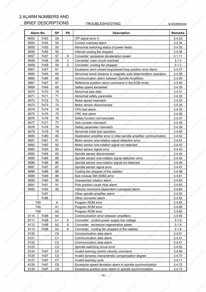
TROUBLESHOOTING B-65285EN/04
- 56 -
2.ALARM NUMBERS AND BRIEF DESCRIPTIONS
Alarm No. SP PS Description Remarks
9053 7n53 53 ITP signal error II 3.4.33 9054 7n54 54 Current overload alarm 3.4.34 9055 7n55 55 Abnormal switching status of power leads 3.4.35 9056 7n56 56 Internal cooling fan stopped 3.4.36 9057 7n57 57 H Converter: excessive deceleration power 3.1.11 9058 7n58 58 3 Converter: main circuit overload 3.1.3 9059 7n59 59 2 Converter: cooling fan stopped 3.1.2 9061 7n61 61 Excessive semi-closed loop/closed loop position error alarm 3.4.37 9065 7n65 65 Abnormal travel distance in magnetic pole determination operation 3.4.38 9066 7n66 66 Communication alarm between Spindle Amplifiers 3.4.29 9067 7n67 67 Reference position return command in the EGB mode 3.4.40 9069 7n69 69 Safety speed exceeded 3.4.30 9070 7n70 70 Abnormal axis data 3.4.31 9071 7n71 71 Abnormal safety parameter 3.4.32 9072 7n72 72 Motor speed mismatch 3.4.33 9073 7n73 73 Motor sensor disconnected 3.4.34 9074 7n74 74 CPU test alarm 3.4.35 9075 7n75 75 CRC test alarm 3.4.36 9076 7n76 76 Safety function not executed 3.4.37 9077 7n77 77 Axis number mismatch 3.4.38 9078 7n78 78 Safety parameter mismatch 3.4.39 9079 7n79 79 Abnormal initial test operation 3.4.40 9080 7n80 80 Destination amplifier error in inter-spindle amplifier communication 3.4.52 9081 7n81 81 Motor sensor one-rotation signal detection error 3.4.41 9082 7n82 82 Motor sensor one-rotation signal not detected 3.4.42 9083 7n83 83 Motor sensor signal error 3.4.43 9084 7n84 84 Spindle sensor disconnected 3.4.44 9085 7n85 85 Spindle sensor one-rotation signal detection error 3.4.45 9086 7n86 86 Spindle sensor one-rotation signal not detected 3.4.46 9087 7n87 87 Spindle sensor signal error 3.4.47 9088 7n88 88 Cooling fan stopped of the radiator 3.4.48 9089 7n89 89 Sub module SM (SSM) error 3.4.61 9090 7n90 90 Unexpected rotation alarm 3.4.62 9091 7n91 91 Pole position count miss alarm 3.4.63 9092 7n92 92 Velocity command-dependent overspeed alarm 3.4.64
7n97 Other spindle amplifier alarm 3.4.52 7n98 Other converter alarm 3.4.52
749 A Program ROM error 3.4.65 749 A1 Program ROM error 3.4.65 749 A2 Program ROM error 3.4.65
9110 7n98 b0 Communication error between amplifiers 3.4.50 9111 7n98 b1 6 Converter: control power supply low voltage 3.1.6 9112 7n98 b2 8 Converter: excessive regenerative power 3.1.8 9113 7n98 b3 A Converter: cooling fan stopped of the radiator 3.1.9 9120 C0 Communication data alarm 3.4.51 9121 C1 Communication data alarm 3.4.51 9122 C2 Communication data alarm 3.4.51 9123 C3 Spindle switching circuit error 3.4.52 9124 7n97 C4 Invalid learning control velocity command 3.4.69 9125 7n97 C5 Invalid dynamic characteristic compensation degree 3.4.70 9127 7n97 C7 Invalid learning cycle 3.4.71 9128 7n97 C8 Excessive speed deviation alarm in spindle synchronization 3.4.72 9129 7n97 C9 Excessive position error alarm in spindle synchronization 3.4.73
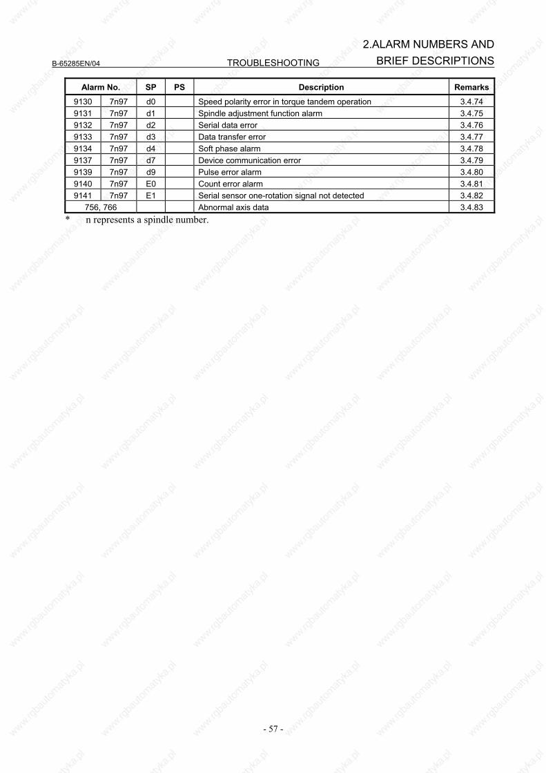
B-65285EN/04 TROUBLESHOOTING
- 57 -
2.ALARM NUMBERS ANDBRIEF DESCRIPTIONS
Alarm No. SP PS Description Remarks
9130 7n97 d0 Speed polarity error in torque tandem operation 3.4.74 9131 7n97 d1 Spindle adjustment function alarm 3.4.75 9132 7n97 d2 Serial data error 3.4.76 9133 7n97 d3 Data transfer error 3.4.77 9134 7n97 d4 Soft phase alarm 3.4.78 9137 7n97 d7 Device communication error 3.4.79 9139 7n97 d9 Pulse error alarm 3.4.80 9140 7n97 E0 Count error alarm 3.4.81 9141 7n97 E1 Serial sensor one-rotation signal not detected 3.4.82
756, 766 Abnormal axis data 3.4.83 * n represents a spindle number.
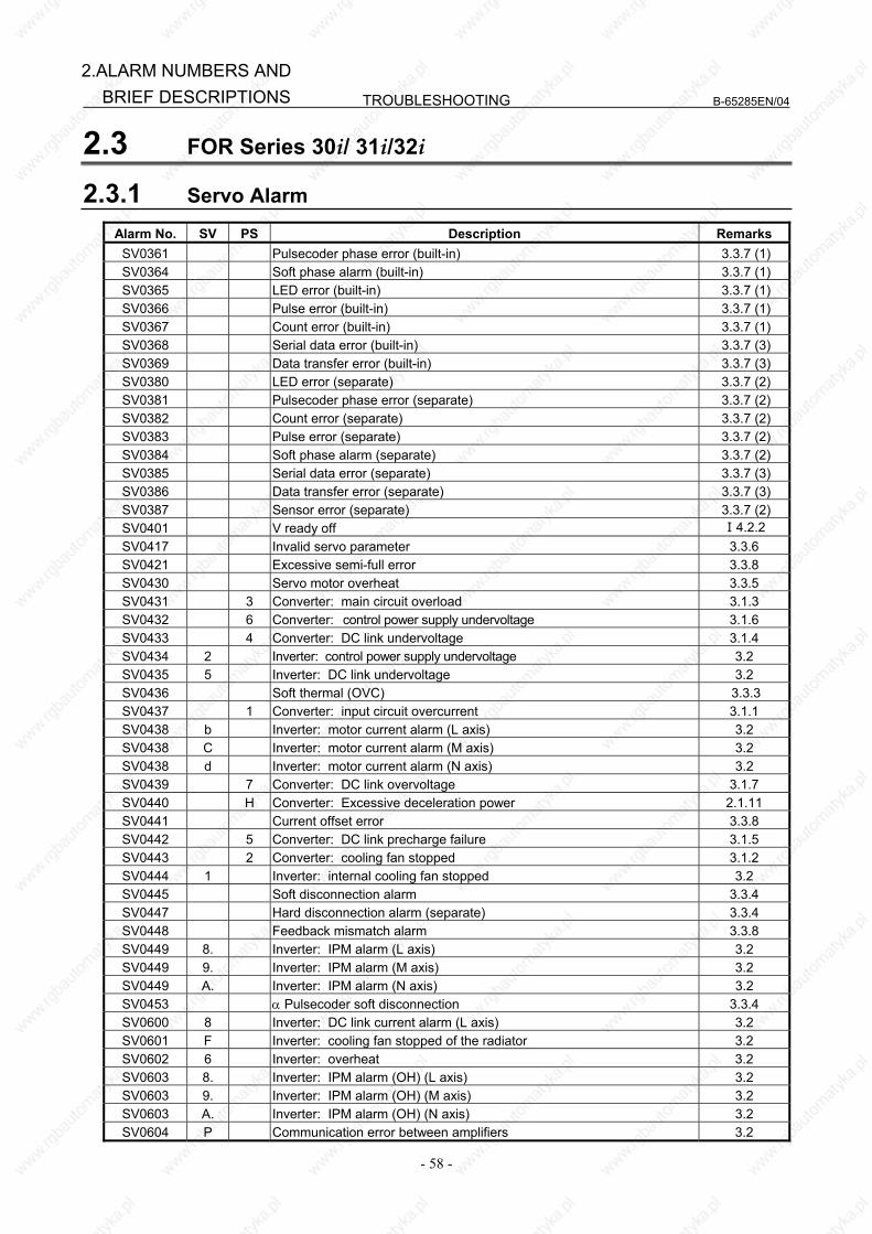
TROUBLESHOOTING B-65285EN/04
- 58 -
2.ALARM NUMBERS AND BRIEF DESCRIPTIONS
2.3 FOR Series 30i/ 31i/32i
2.3.1 Servo Alarm
Alarm No. SV PS Description Remarks SV0361 Pulsecoder phase error (built-in) 3.3.7 (1) SV0364 Soft phase alarm (built-in) 3.3.7 (1) SV0365 LED error (built-in) 3.3.7 (1) SV0366 Pulse error (built-in) 3.3.7 (1) SV0367 Count error (built-in) 3.3.7 (1) SV0368 Serial data error (built-in) 3.3.7 (3) SV0369 Data transfer error (built-in) 3.3.7 (3) SV0380 LED error (separate) 3.3.7 (2) SV0381 Pulsecoder phase error (separate) 3.3.7 (2) SV0382 Count error (separate) 3.3.7 (2) SV0383 Pulse error (separate) 3.3.7 (2) SV0384 Soft phase alarm (separate) 3.3.7 (2) SV0385 Serial data error (separate) 3.3.7 (3) SV0386 Data transfer error (separate) 3.3.7 (3) SV0387 Sensor error (separate) 3.3.7 (2) SV0401 V ready off Ⅰ4.2.2 SV0417 Invalid servo parameter 3.3.6 SV0421 Excessive semi-full error 3.3.8 SV0430 Servo motor overheat 3.3.5 SV0431 3 Converter: main circuit overload 3.1.3 SV0432 6 Converter: control power supply undervoltage 3.1.6 SV0433 4 Converter: DC link undervoltage 3.1.4 SV0434 2 Inverter: control power supply undervoltage 3.2 SV0435 5 Inverter: DC link undervoltage 3.2 SV0436 Soft thermal (OVC) 3.3.3 SV0437 1 Converter: input circuit overcurrent 3.1.1 SV0438 b Inverter: motor current alarm (L axis) 3.2 SV0438 C Inverter: motor current alarm (M axis) 3.2 SV0438 d Inverter: motor current alarm (N axis) 3.2 SV0439 7 Converter: DC link overvoltage 3.1.7 SV0440 H Converter: Excessive deceleration power 2.1.11 SV0441 Current offset error 3.3.8 SV0442 5 Converter: DC link precharge failure 3.1.5 SV0443 2 Converter: cooling fan stopped 3.1.2 SV0444 1 Inverter: internal cooling fan stopped 3.2 SV0445 Soft disconnection alarm 3.3.4 SV0447 Hard disconnection alarm (separate) 3.3.4 SV0448 Feedback mismatch alarm 3.3.8 SV0449 8. Inverter: IPM alarm (L axis) 3.2 SV0449 9. Inverter: IPM alarm (M axis) 3.2 SV0449 A. Inverter: IPM alarm (N axis) 3.2 SV0453 α Pulsecoder soft disconnection 3.3.4 SV0600 8 Inverter: DC link current alarm (L axis) 3.2 SV0601 F Inverter: cooling fan stopped of the radiator 3.2 SV0602 6 Inverter: overheat 3.2 SV0603 8. Inverter: IPM alarm (OH) (L axis) 3.2 SV0603 9. Inverter: IPM alarm (OH) (M axis) 3.2 SV0603 A. Inverter: IPM alarm (OH) (N axis) 3.2 SV0604 P Communication error between amplifiers 3.2
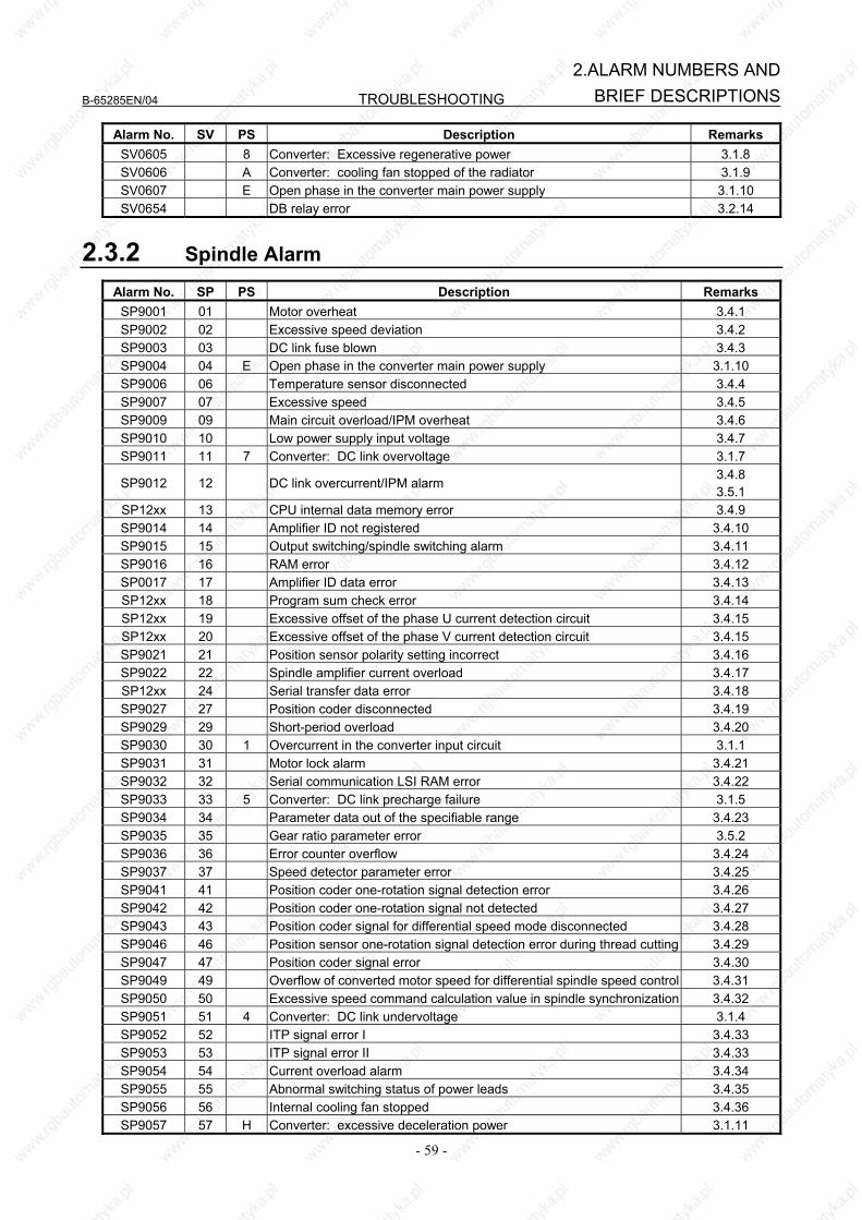
B-65285EN/04 TROUBLESHOOTING
- 59 -
2.ALARM NUMBERS ANDBRIEF DESCRIPTIONS
Alarm No. SV PS Description Remarks SV0605 8 Converter: Excessive regenerative power 3.1.8 SV0606 A Converter: cooling fan stopped of the radiator 3.1.9 SV0607 E Open phase in the converter main power supply 3.1.10 SV0654 DB relay error 3.2.14
2.3.2 Spindle Alarm
Alarm No. SP PS Description Remarks SP9001 01 Motor overheat 3.4.1 SP9002 02 Excessive speed deviation 3.4.2 SP9003 03 DC link fuse blown 3.4.3 SP9004 04 E Open phase in the converter main power supply 3.1.10 SP9006 06 Temperature sensor disconnected 3.4.4 SP9007 07 Excessive speed 3.4.5 SP9009 09 Main circuit overload/IPM overheat 3.4.6 SP9010 10 Low power supply input voltage 3.4.7 SP9011 11 7 Converter: DC link overvoltage 3.1.7
SP9012 12 DC link overcurrent/IPM alarm 3.4.8 3.5.1
SP12xx 13 CPU internal data memory error 3.4.9 SP9014 14 Amplifier ID not registered 3.4.10 SP9015 15 Output switching/spindle switching alarm 3.4.11 SP9016 16 RAM error 3.4.12 SP0017 17 Amplifier ID data error 3.4.13 SP12xx 18 Program sum check error 3.4.14 SP12xx 19 Excessive offset of the phase U current detection circuit 3.4.15 SP12xx 20 Excessive offset of the phase V current detection circuit 3.4.15 SP9021 21 Position sensor polarity setting incorrect 3.4.16 SP9022 22 Spindle amplifier current overload 3.4.17 SP12xx 24 Serial transfer data error 3.4.18 SP9027 27 Position coder disconnected 3.4.19 SP9029 29 Short-period overload 3.4.20 SP9030 30 1 Overcurrent in the converter input circuit 3.1.1 SP9031 31 Motor lock alarm 3.4.21 SP9032 32 Serial communication LSI RAM error 3.4.22 SP9033 33 5 Converter: DC link precharge failure 3.1.5 SP9034 34 Parameter data out of the specifiable range 3.4.23 SP9035 35 Gear ratio parameter error 3.5.2 SP9036 36 Error counter overflow 3.4.24 SP9037 37 Speed detector parameter error 3.4.25 SP9041 41 Position coder one-rotation signal detection error 3.4.26 SP9042 42 Position coder one-rotation signal not detected 3.4.27 SP9043 43 Position coder signal for differential speed mode disconnected 3.4.28 SP9046 46 Position sensor one-rotation signal detection error during thread cutting 3.4.29 SP9047 47 Position coder signal error 3.4.30 SP9049 49 Overflow of converted motor speed for differential spindle speed control 3.4.31 SP9050 50 Excessive speed command calculation value in spindle synchronization 3.4.32 SP9051 51 4 Converter: DC link undervoltage 3.1.4 SP9052 52 ITP signal error I 3.4.33 SP9053 53 ITP signal error II 3.4.33 SP9054 54 Current overload alarm 3.4.34 SP9055 55 Abnormal switching status of power leads 3.4.35 SP9056 56 Internal cooling fan stopped 3.4.36 SP9057 57 H Converter: excessive deceleration power 3.1.11
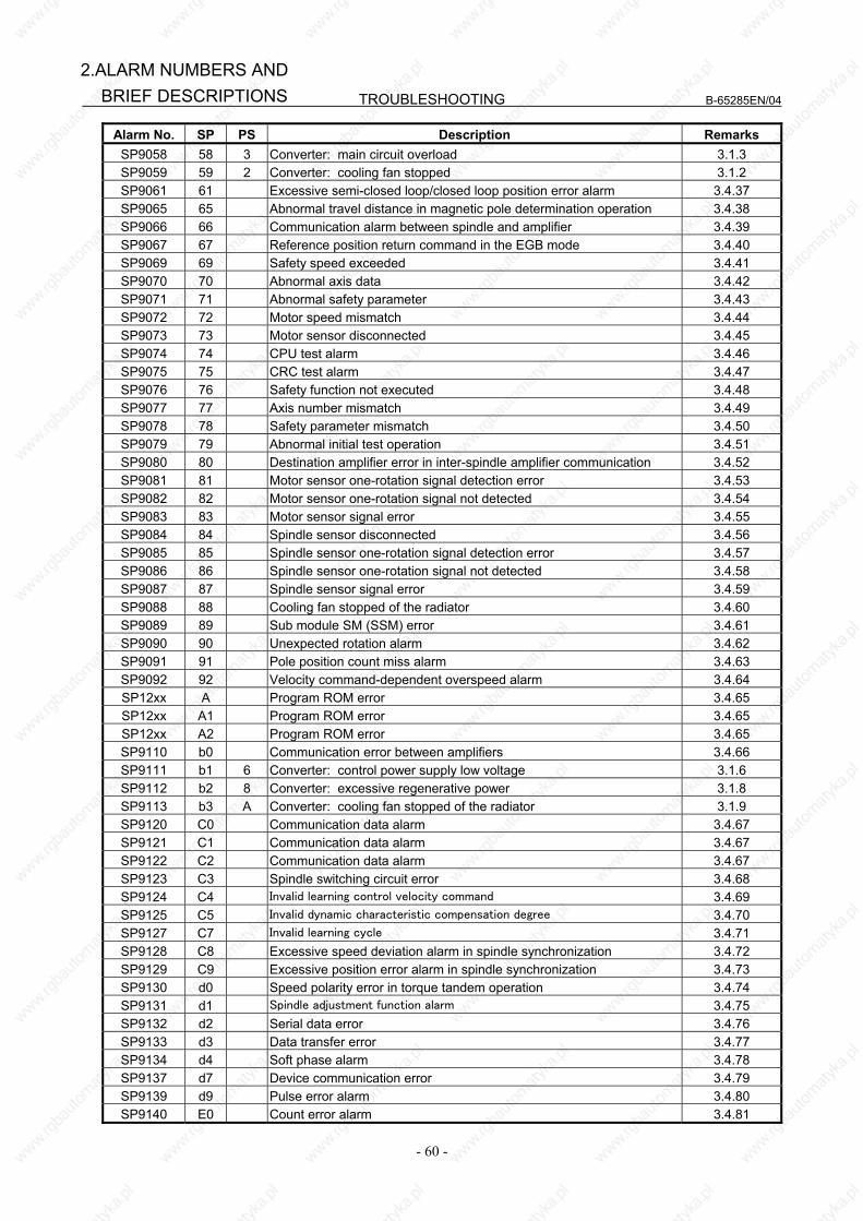
TROUBLESHOOTING B-65285EN/04
- 60 -
2.ALARM NUMBERS AND BRIEF DESCRIPTIONS
Alarm No. SP PS Description Remarks SP9058 58 3 Converter: main circuit overload 3.1.3 SP9059 59 2 Converter: cooling fan stopped 3.1.2 SP9061 61 Excessive semi-closed loop/closed loop position error alarm 3.4.37 SP9065 65 Abnormal travel distance in magnetic pole determination operation 3.4.38 SP9066 66 Communication alarm between spindle and amplifier 3.4.39 SP9067 67 Reference position return command in the EGB mode 3.4.40 SP9069 69 Safety speed exceeded 3.4.41 SP9070 70 Abnormal axis data 3.4.42 SP9071 71 Abnormal safety parameter 3.4.43 SP9072 72 Motor speed mismatch 3.4.44 SP9073 73 Motor sensor disconnected 3.4.45 SP9074 74 CPU test alarm 3.4.46 SP9075 75 CRC test alarm 3.4.47 SP9076 76 Safety function not executed 3.4.48 SP9077 77 Axis number mismatch 3.4.49 SP9078 78 Safety parameter mismatch 3.4.50 SP9079 79 Abnormal initial test operation 3.4.51 SP9080 80 Destination amplifier error in inter-spindle amplifier communication 3.4.52 SP9081 81 Motor sensor one-rotation signal detection error 3.4.53 SP9082 82 Motor sensor one-rotation signal not detected 3.4.54 SP9083 83 Motor sensor signal error 3.4.55 SP9084 84 Spindle sensor disconnected 3.4.56 SP9085 85 Spindle sensor one-rotation signal detection error 3.4.57 SP9086 86 Spindle sensor one-rotation signal not detected 3.4.58 SP9087 87 Spindle sensor signal error 3.4.59 SP9088 88 Cooling fan stopped of the radiator 3.4.60 SP9089 89 Sub module SM (SSM) error 3.4.61 SP9090 90 Unexpected rotation alarm 3.4.62 SP9091 91 Pole position count miss alarm 3.4.63 SP9092 92 Velocity command-dependent overspeed alarm 3.4.64 SP12xx A Program ROM error 3.4.65 SP12xx A1 Program ROM error 3.4.65 SP12xx A2 Program ROM error 3.4.65 SP9110 b0 Communication error between amplifiers 3.4.66 SP9111 b1 6 Converter: control power supply low voltage 3.1.6 SP9112 b2 8 Converter: excessive regenerative power 3.1.8 SP9113 b3 A Converter: cooling fan stopped of the radiator 3.1.9 SP9120 C0 Communication data alarm 3.4.67 SP9121 C1 Communication data alarm 3.4.67 SP9122 C2 Communication data alarm 3.4.67 SP9123 C3 Spindle switching circuit error 3.4.68 SP9124 C4 Invalid learning control velocity command 3.4.69 SP9125 C5 Invalid dynamic characteristic compensation degree 3.4.70 SP9127 C7 Invalid learning cycle 3.4.71 SP9128 C8 Excessive speed deviation alarm in spindle synchronization 3.4.72 SP9129 C9 Excessive position error alarm in spindle synchronization 3.4.73 SP9130 d0 Speed polarity error in torque tandem operation 3.4.74 SP9131 d1 Spindle adjustment function alarm 3.4.75 SP9132 d2 Serial data error 3.4.76 SP9133 d3 Data transfer error 3.4.77 SP9134 d4 Soft phase alarm 3.4.78 SP9137 d7 Device communication error 3.4.79 SP9139 d9 Pulse error alarm 3.4.80 SP9140 E0 Count error alarm 3.4.81
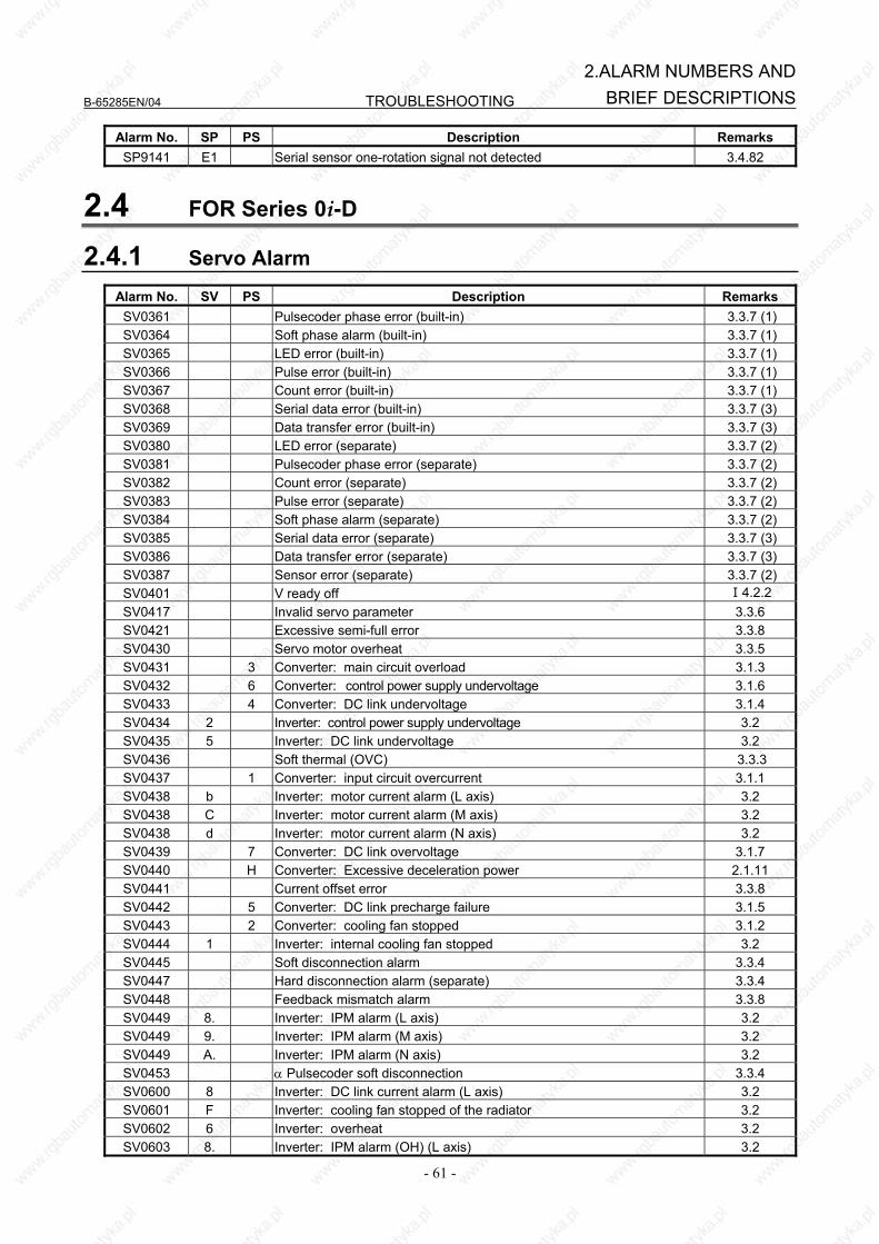
B-65285EN/04 TROUBLESHOOTING
- 61 -
2.ALARM NUMBERS ANDBRIEF DESCRIPTIONS
Alarm No. SP PS Description Remarks SP9141 E1 Serial sensor one-rotation signal not detected 3.4.82
2.4 FOR Series 0i-D
2.4.1 Servo Alarm
Alarm No. SV PS Description Remarks SV0361 Pulsecoder phase error (built-in) 3.3.7 (1) SV0364 Soft phase alarm (built-in) 3.3.7 (1) SV0365 LED error (built-in) 3.3.7 (1) SV0366 Pulse error (built-in) 3.3.7 (1) SV0367 Count error (built-in) 3.3.7 (1) SV0368 Serial data error (built-in) 3.3.7 (3) SV0369 Data transfer error (built-in) 3.3.7 (3) SV0380 LED error (separate) 3.3.7 (2) SV0381 Pulsecoder phase error (separate) 3.3.7 (2) SV0382 Count error (separate) 3.3.7 (2) SV0383 Pulse error (separate) 3.3.7 (2) SV0384 Soft phase alarm (separate) 3.3.7 (2) SV0385 Serial data error (separate) 3.3.7 (3) SV0386 Data transfer error (separate) 3.3.7 (3) SV0387 Sensor error (separate) 3.3.7 (2) SV0401 V ready off Ⅰ4.2.2 SV0417 Invalid servo parameter 3.3.6 SV0421 Excessive semi-full error 3.3.8 SV0430 Servo motor overheat 3.3.5 SV0431 3 Converter: main circuit overload 3.1.3 SV0432 6 Converter: control power supply undervoltage 3.1.6 SV0433 4 Converter: DC link undervoltage 3.1.4 SV0434 2 Inverter: control power supply undervoltage 3.2 SV0435 5 Inverter: DC link undervoltage 3.2 SV0436 Soft thermal (OVC) 3.3.3 SV0437 1 Converter: input circuit overcurrent 3.1.1 SV0438 b Inverter: motor current alarm (L axis) 3.2 SV0438 C Inverter: motor current alarm (M axis) 3.2 SV0438 d Inverter: motor current alarm (N axis) 3.2 SV0439 7 Converter: DC link overvoltage 3.1.7 SV0440 H Converter: Excessive deceleration power 2.1.11 SV0441 Current offset error 3.3.8 SV0442 5 Converter: DC link precharge failure 3.1.5 SV0443 2 Converter: cooling fan stopped 3.1.2 SV0444 1 Inverter: internal cooling fan stopped 3.2 SV0445 Soft disconnection alarm 3.3.4 SV0447 Hard disconnection alarm (separate) 3.3.4 SV0448 Feedback mismatch alarm 3.3.8 SV0449 8. Inverter: IPM alarm (L axis) 3.2 SV0449 9. Inverter: IPM alarm (M axis) 3.2 SV0449 A. Inverter: IPM alarm (N axis) 3.2 SV0453 α Pulsecoder soft disconnection 3.3.4 SV0600 8 Inverter: DC link current alarm (L axis) 3.2 SV0601 F Inverter: cooling fan stopped of the radiator 3.2 SV0602 6 Inverter: overheat 3.2 SV0603 8. Inverter: IPM alarm (OH) (L axis) 3.2
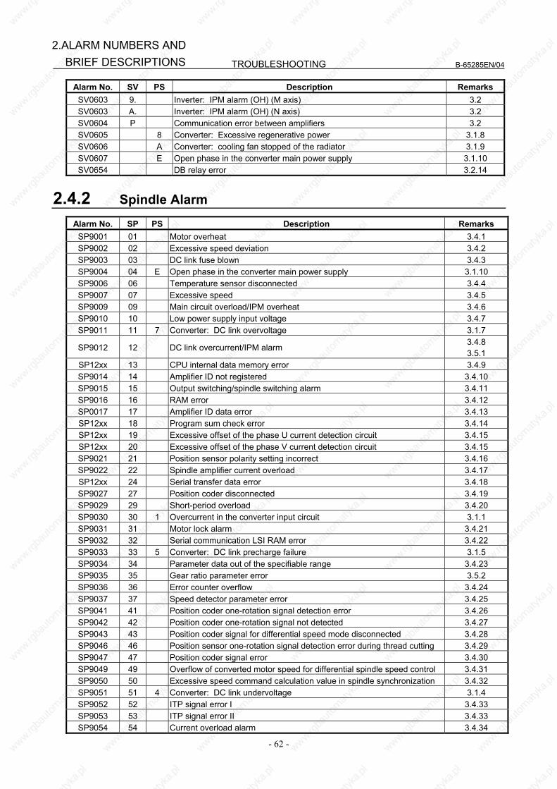
TROUBLESHOOTING B-65285EN/04
- 62 -
2.ALARM NUMBERS AND BRIEF DESCRIPTIONS
Alarm No. SV PS Description Remarks SV0603 9. Inverter: IPM alarm (OH) (M axis) 3.2 SV0603 A. Inverter: IPM alarm (OH) (N axis) 3.2 SV0604 P Communication error between amplifiers 3.2 SV0605 8 Converter: Excessive regenerative power 3.1.8 SV0606 A Converter: cooling fan stopped of the radiator 3.1.9 SV0607 E Open phase in the converter main power supply 3.1.10 SV0654 DB relay error 3.2.14
2.4.2 Spindle Alarm
Alarm No. SP PS Description Remarks SP9001 01 Motor overheat 3.4.1 SP9002 02 Excessive speed deviation 3.4.2 SP9003 03 DC link fuse blown 3.4.3 SP9004 04 E Open phase in the converter main power supply 3.1.10 SP9006 06 Temperature sensor disconnected 3.4.4 SP9007 07 Excessive speed 3.4.5 SP9009 09 Main circuit overload/IPM overheat 3.4.6 SP9010 10 Low power supply input voltage 3.4.7 SP9011 11 7 Converter: DC link overvoltage 3.1.7
SP9012 12 DC link overcurrent/IPM alarm 3.4.8 3.5.1
SP12xx 13 CPU internal data memory error 3.4.9 SP9014 14 Amplifier ID not registered 3.4.10 SP9015 15 Output switching/spindle switching alarm 3.4.11 SP9016 16 RAM error 3.4.12 SP0017 17 Amplifier ID data error 3.4.13 SP12xx 18 Program sum check error 3.4.14 SP12xx 19 Excessive offset of the phase U current detection circuit 3.4.15 SP12xx 20 Excessive offset of the phase V current detection circuit 3.4.15 SP9021 21 Position sensor polarity setting incorrect 3.4.16 SP9022 22 Spindle amplifier current overload 3.4.17 SP12xx 24 Serial transfer data error 3.4.18 SP9027 27 Position coder disconnected 3.4.19 SP9029 29 Short-period overload 3.4.20 SP9030 30 1 Overcurrent in the converter input circuit 3.1.1 SP9031 31 Motor lock alarm 3.4.21 SP9032 32 Serial communication LSI RAM error 3.4.22 SP9033 33 5 Converter: DC link precharge failure 3.1.5 SP9034 34 Parameter data out of the specifiable range 3.4.23 SP9035 35 Gear ratio parameter error 3.5.2 SP9036 36 Error counter overflow 3.4.24 SP9037 37 Speed detector parameter error 3.4.25 SP9041 41 Position coder one-rotation signal detection error 3.4.26 SP9042 42 Position coder one-rotation signal not detected 3.4.27 SP9043 43 Position coder signal for differential speed mode disconnected 3.4.28 SP9046 46 Position sensor one-rotation signal detection error during thread cutting 3.4.29 SP9047 47 Position coder signal error 3.4.30 SP9049 49 Overflow of converted motor speed for differential spindle speed control 3.4.31 SP9050 50 Excessive speed command calculation value in spindle synchronization 3.4.32 SP9051 51 4 Converter: DC link undervoltage 3.1.4 SP9052 52 ITP signal error I 3.4.33 SP9053 53 ITP signal error II 3.4.33 SP9054 54 Current overload alarm 3.4.34
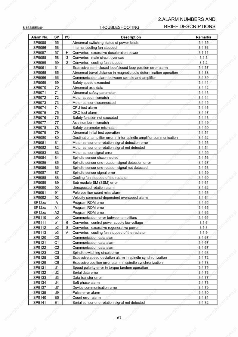
B-65285EN/04 TROUBLESHOOTING
- 63 -
2.ALARM NUMBERS ANDBRIEF DESCRIPTIONS
Alarm No. SP PS Description Remarks SP9055 55 Abnormal switching status of power leads 3.4.35 SP9056 56 Internal cooling fan stopped 3.4.36 SP9057 57 H Converter: excessive deceleration power 3.1.11 SP9058 58 3 Converter: main circuit overload 3.1.3 SP9059 59 2 Converter: cooling fan stopped 3.1.2 SP9061 61 Excessive semi-closed loop/closed loop position error alarm 3.4.37 SP9065 65 Abnormal travel distance in magnetic pole determination operation 3.4.38 SP9066 66 Communication alarm between spindle and amplifier 3.4.39 SP9069 69 Safety speed exceeded 3.4.41 SP9070 70 Abnormal axis data 3.4.42 SP9071 71 Abnormal safety parameter 3.4.43 SP9072 72 Motor speed mismatch 3.4.44 SP9073 73 Motor sensor disconnected 3.4.45 SP9074 74 CPU test alarm 3.4.46 SP9075 75 CRC test alarm 3.4.47 SP9076 76 Safety function not executed 3.4.48 SP9077 77 Axis number mismatch 3.4.49 SP9078 78 Safety parameter mismatch 3.4.50 SP9079 79 Abnormal initial test operation 3.4.51 SP9080 80 Destination amplifier error in inter-spindle amplifier communication 3.4.52 SP9081 81 Motor sensor one-rotation signal detection error 3.4.53 SP9082 82 Motor sensor one-rotation signal not detected 3.4.54 SP9083 83 Motor sensor signal error 3.4.55 SP9084 84 Spindle sensor disconnected 3.4.56 SP9085 85 Spindle sensor one-rotation signal detection error 3.4.57 SP9086 86 Spindle sensor one-rotation signal not detected 3.4.58 SP9087 87 Spindle sensor signal error 3.4.59 SP9088 88 Cooling fan stopped of the radiator 3.4.60 SP9089 89 Sub module SM (SSM) error 3.4.61 SP9090 90 Unexpected rotation alarm 3.4.62 SP9091 91 Pole position count miss alarm 3.4.63 SP9092 92 Velocity command-dependent overspeed alarm 3.4.64 SP12xx A Program ROM error 3.4.65 SP12xx A1 Program ROM error 3.4.65 SP12xx A2 Program ROM error 3.4.65 SP9110 b0 Communication error between amplifiers 3.4.66 SP9111 b1 6 Converter: control power supply low voltage 3.1.6 SP9112 b2 8 Converter: excessive regenerative power 3.1.8 SP9113 b3 A Converter: cooling fan stopped of the radiator 3.1.9 SP9120 C0 Communication data alarm 3.4.67 SP9121 C1 Communication data alarm 3.4.67 SP9122 C2 Communication data alarm 3.4.67 SP9123 C3 Spindle switching circuit error 3.4.68 SP9128 C8 Excessive speed deviation alarm in spindle synchronization 3.4.72 SP9129 C9 Excessive position error alarm in spindle synchronization 3.4.73 SP9131 d1 Speed polarity error in torque tandem operation 3.4.75 SP9132 d2 Serial data error 3.4.76 SP9133 d3 Data transfer error 3.4.77 SP9134 d4 Soft phase alarm 3.4.78 SP9137 d7 Device communication error 3.4.79 SP9139 d9 Pulse error alarm 3.4.80 SP9140 E0 Count error alarm 3.4.81 SP9141 E1 Serial sensor one-rotation signal not detected 3.4.82
TROUBLESHOOTING B-65285EN/04
- 64 -
3.TROUBLESHOOTING AND ACTION
3 TROUBLESHOOTING AND ACTION
3.1 POWER SUPPLY (αiPS, αiPSR)
If an alarm occurs, in the STATUS display, the ALM LED lights red, and the one-digit 7-segment display indicates an alarm code or warning code. The meaning of each warning code is the same as that of the corresponding alarm code. If a warning code is displayed, an alarm condition will occur in a certain period of time. The Power Supply remains operable while the warning code stays displayed. Example of an alarm Example of a warning code display code display
3.1.1 No LED Display (αiPS, αiPSR) (1) Meaning The 200-V control power (CX1A) is not supplied. Alternatively, the 24-VDC power is short-circuited. (2) Cause and troubleshooting
(a) Check whether the circuit breaker for the control power supply is off. When a lightning surge absorber is connected immediately following the circuit breaker, check
whether the lightning surge absorber is short-circuited by lightning. If the lightning surge absorber is short-circuited, replace it.
(b) Disconnect the cable from the connector CX1A and turn the control power on. If "-" is displayed, the 24-V power to a Servo Amplifier or Spindle Amplifier may be short-circuited. → Detect the amplifier which causes the power to be short-circuited by sequentially
connecting the cable from the Power Supply and replace it. (c) Disconnect the cable from the connector CX4 and turn the control power on. If "-" is displayed,
the external 24-V power may be connected to pin 3 of CX4 incorrectly. → Correct the connection.
3.1.2 Alarm Code 1 (αiPS)
For the αiPS-5.5 to -15 and 11HV to 18HV (1) Meaning The main circuit power module (IPM) has detected an abnormal condition. (2) Cause and troubleshooting
(a) Control supply voltage decrease of the power module (IPM) → Replace the power unit. (b) Input supply voltage imbalance → Check the input power supply specification. (c) The specification of the AC reactor does not match the PSM in use. → Check the PSM and the specification of the AC reactor.
B-65285EN/04 TROUBLESHOOTING
- 65 -
3.TROUBLESHOOTING ANDACTION
(d) IPM failure → Replace the IPM.
For the αiPS15 to –55 and 30HV to 100HV
(1) Meaning Overcurrent flowed into the input of the main circuit. (2) Cause and troubleshooting
(a) Input supply voltage imbalance → Check the input power supply specification. (b) The specification of the AC reactor does not match the PSM in use. → Check the PSM and the specification of the AC reactor. (c) IGBT defective → Replace IGBT.
3.1.3 Alarm Code 2 (αiPS, αiPSR) (1) Meaning A cooling fan for the control circuit has stopped. With the A06B-6140-HXXX or A06B-6150-HXXX (an upgrade version of PS), this alarm is also
issued when a unit stirring fan has stopped.
(2) Cause and troubleshooting (a) Cooling fan broken Check whether the cooling fan rotates normally. → Replace it. (b) Internal stirring fan broken (only with an upgrade version of PS)
→ Replace it.
3.1.4 Alarm Code 3 (αiPS) (1) Meaning The temperature of the main circuit heat sink has risen abnormally. (2) Cause and troubleshooting
(a) Cooling fan for the main circuit broken Check whether the cooling fan for the main circuit rotates normally.
→ Replace it. (b) Dust accumulation
→ Clean the cooling system with a vacuum cleaner or the factory air blower. (c) Overload
→ Examine the operating conditions. (d) Poor installation of the control printed-circuit board
→ Be sure to push the faceplate as far as it will go. (This alarm may be displayed if one of the connectors for connection between the control printed-circuit board and power printed-circuit board is detached.)
3.1.5 Alarm Code 4 (αiPS, αiPSR) (1) Meaning In the main circuit, the DC voltage (DC link) has dropped. (2) Cause and troubleshooting
(a) A small power dip has occurred. → Check the power supply.

TROUBLESHOOTING B-65285EN/04
- 66 -
3.TROUBLESHOOTING AND ACTION
(b) Low input power supply voltage → Check the power supply specification.
(c) The main circuit power supply may have been switched off with an emergency stop state released. → Check the sequence.
3.1.6 Alarm Code 5 (αiPS, αiPSR) (1) Meaning The main circuit capacitor was not recharged within the specified time. (2) Cause and troubleshooting
(a) Too many Servo Amplifier and/or Spindle Amplifier units are connected. → Check the specification of the PSM.
(b) The DC link is short-circuited. → Check the connection.
(c) The recharge current limiting resistor is defective. → Replace the distributing board.
3.1.7 Alarm Code 6 (αiPS, αiPSR) (1) Meaning The control power supply voltage decrease. The 24-V power supply is abnormal in the Power Supply. (Internal fuse blown) (2) Cause and troubleshooting
(a) Input voltage decrease → Check the power supply.
(b) Power Supply broken → If this alarm is issued just by turning the control power on, replace the Power Supply.
3.1.8 Alarm Code 7 (αiPS, αiPSR) (1) Meaning In the main circuit, the DC voltage at the DC link is abnormally high. (2) Cause and troubleshooting
(a) Excessive regenerated power The PSM does not have a sufficient capacity.
→ Check the specification of the PSM. (b) The output impedance of the AC power source is too high.
→ Check the power source output impedance. (Normal if the voltage variation at maximum output time is within 7%)
(c) The main circuit power supply may have been switched off with an emergency stop state released. → Check the sequence.
3.1.9 Alarm Code 8 (αiPSR) (1) Meaning There is excessive short-term regenerative power. (2) Cause and troubleshooting
(a) Insufficient regenerative resistance → Review the specification of the regenerative resistance.
B-65285EN/04 TROUBLESHOOTING
- 67 -
3.TROUBLESHOOTING ANDACTION
(b) Regenerative circuit failure → The regenerative circuit is abnormal. Replace the PSMR.
3.1.10 Alarm Code A (αiPS) (1) Meaning A cooling fan of external cooling fin has stopped. With the A06B-6110-HXXX or A06B-6120-HXXX, this alarm is also issued when a unit stirring fan
has stopped. (2) Cause and troubleshooting
(a) Cooling fan for the radiator cooling fin broken Check whether the cooling fan for the radiator cooling fin rotates normally.
→ Replace it. (b) Unit stirring fan broken (A06B-6110-HXXX,A06B-6120-HXXX のみ) Check whether the unit stirring fan rotates normally.
→ Replace it. (c) Poor installation of the control printed-circuit board
→ Be sure to install the control printed-circuit board. (This alarm may be issued if one of the connectors for connection between the control
printed-circuit board and power printed-circuit board become loose.) (d) Poor installation of the control printed-circuit board
→ Be sure to push the faceplate as far as it will go. (This alarm may be displayed if one of the connectors for connection between the control printed-circuit board and power printed-circuit board is detached.)
3.1.11 Alarm Code E (αiPS, αiPSR) (1) Meaning The input power supply is abnormal (open phase). (2) Cause and troubleshooting
(a) The input power supply has an open phase. Check the power supply voltage.
→ If there is no problem with the power supply voltage, check the connections.
3.1.12 Alarm Code H (αiPSR) (1) Meaning The temperature of the regenerative resistor has arisen abnormally. (2) Cause and troubleshooting
(a) Regenerative resistance not detected → Check the wiring for the regenerative resistance.
(b) Insufficient regenerative resistance → Review the specification for the regenerative resistance.
(c) Excessive regenerative power → Reduce the frequency at which acceleration/ deceleration occurs.
(d) Regenerative resistor cooling fan stopped → Check to see if the regenerative resistor cooling fan has stopped.
3.1.13 Alarm Code P (αiPS, αiPSR) (1) Meaning Communication error between amplifiers
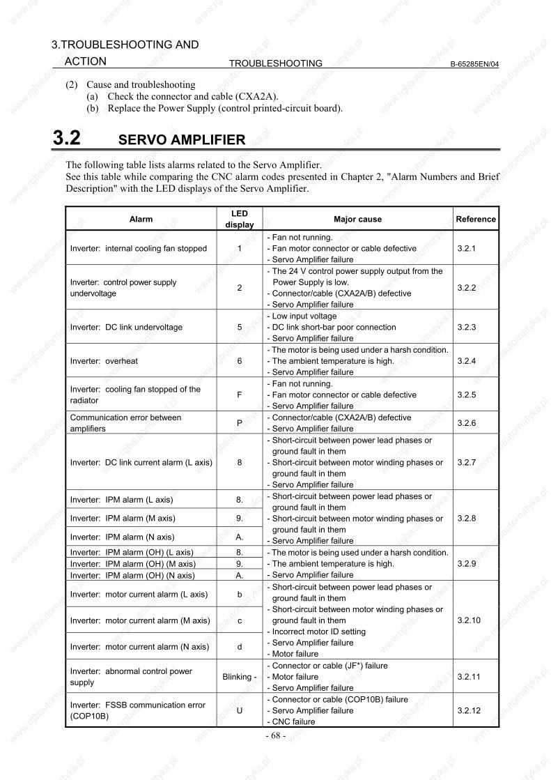
TROUBLESHOOTING B-65285EN/04
- 68 -
3.TROUBLESHOOTING AND ACTION
(2) Cause and troubleshooting (a) Check the connector and cable (CXA2A). (b) Replace the Power Supply (control printed-circuit board).
3.2 SERVO AMPLIFIER The following table lists alarms related to the Servo Amplifier. See this table while comparing the CNC alarm codes presented in Chapter 2, "Alarm Numbers and Brief Description" with the LED displays of the Servo Amplifier.
Alarm LED display Major cause Reference
Inverter: internal cooling fan stopped 1 - Fan not running. - Fan motor connector or cable defective - Servo Amplifier failure
3.2.1
Inverter: control power supply undervoltage
2
- The 24 V control power supply output from the Power Supply is low.
- Connector/cable (CXA2A/B) defective - Servo Amplifier failure
3.2.2
Inverter: DC link undervoltage 5 - Low input voltage - DC link short-bar poor connection - Servo Amplifier failure
3.2.3
Inverter: overheat 6 - The motor is being used under a harsh condition. - The ambient temperature is high. - Servo Amplifier failure
3.2.4
Inverter: cooling fan stopped of the radiator
F - Fan not running. - Fan motor connector or cable defective - Servo Amplifier failure
3.2.5
Communication error between amplifiers
P - Connector/cable (CXA2A/B) defective - Servo Amplifier failure
3.2.6
Inverter: DC link current alarm (L axis) 8
- Short-circuit between power lead phases or ground fault in them
- Short-circuit between motor winding phases or ground fault in them
- Servo Amplifier failure
3.2.7
Inverter: IPM alarm (L axis) 8.
Inverter: IPM alarm (M axis) 9.
Inverter: IPM alarm (N axis) A.
- Short-circuit between power lead phases or ground fault in them
- Short-circuit between motor winding phases or ground fault in them
- Servo Amplifier failure
3.2.8
Inverter: IPM alarm (OH) (L axis) 8. Inverter: IPM alarm (OH) (M axis) 9. Inverter: IPM alarm (OH) (N axis) A.
- The motor is being used under a harsh condition. - The ambient temperature is high. - Servo Amplifier failure
3.2.9
Inverter: motor current alarm (L axis) b
Inverter: motor current alarm (M axis) c
Inverter: motor current alarm (N axis) d
- Short-circuit between power lead phases or ground fault in them
- Short-circuit between motor winding phases or ground fault in them
- Incorrect motor ID setting - Servo Amplifier failure - Motor failure
3.2.10
Inverter: abnormal control power supply
Blinking -- Connector or cable (JF*) failure - Motor failure - Servo Amplifier failure
3.2.11
Inverter: FSSB communication error (COP10B)
U - Connector or cable (COP10B) failure - Servo Amplifier failure - CNC failure
3.2.12
B-65285EN/04 TROUBLESHOOTING
- 69 -
3.TROUBLESHOOTING ANDACTION
Alarm LED display Major cause Reference
Inverter: FSSB communication error (COP10A)
L - Connector or cable (COP10A) failure - Servo Amplifier failure
3.2.13
3.2.1 Alarm Code 1 (1) Meaning Inverter: internal cooling fan stopped (2) Cause and troubleshooting
(a) Check whether there is any foreign material in the fan. (b) Be sure to push the faceplate (control printed-circuit board) as far as it will go. (c) Check that the fan connector is attached correctly. (d) Replace the fan. (e) Replace the Servo Amplifier.
3.2.2 Alarm Code 2 (1) Meaning Inverter: control power supply undervoltage (2) Cause and troubleshooting
(a) Check the three-phase input voltage of the amplifier (the voltage shall not be lower than 85% of the rated input voltage).
(b) Check the 24 V power supply voltage output from the Power Supply (the voltage shall normally not lower than 22.8 V).
(c) Check the connector and cable (CXA2A/B). (d) Replace the Servo Amplifier.
3.2.3 Alarm Code 5 (1) Meaning Inverter: DC link undervoltage (2) Cause and troubleshooting
(a) Check that the screws for the DC link connection cable (bar) are tight. (b) If a DC link low voltage alarm condition occurs in more than one module, see Subsection 3.1.4,
"Alarm code 4" for explanations about how to troubleshoot the Power Supply. (c) If a DC link low voltage alarm condition occurs in one Servo Amplifier only, be sure to push the
faceplate (control printed-circuit board) of that Servo Amplifier as far as it will go. (d) Replace the Servo Amplifier in which this alarm has occurred.
3.2.4 Alarm Code 6 (1) Meaning Inverter: overheat (2) Cause and troubleshooting
(a) Check that the motor is being used at or below its continuous rating. (b) Check that the cooling capacity of the cabinet is sufficient (inspect the fans and filters). (c) Check that the ambient temperature is not too high. (d) Be sure to push the faceplate (control printed-circuit board) as far as it will go. (e) Replace the Servo Amplifier.
TROUBLESHOOTING B-65285EN/04
- 70 -
3.TROUBLESHOOTING AND ACTION
3.2.5 Alarm Code F (1) Meaning Inverter: cooling fan stopped of the radiator (2) Cause and troubleshooting
(a) Check whether there is any foreign material in the fan. (b) Be sure to push the faceplate (control printed-circuit board) as far as it will go. (c) Check that the fan connector is attached correctly. (d) Replace the fan. (e) Replace the Servo Amplifier.
3.2.6 Alarm Code P (1) Meaning Communication error between amplifiers (2) Cause and troubleshooting
(a) Check the connector and cable (CXA2A/B). (b) Replace the control printed-circuit board. (c) Replace the Servo Amplifier.
3.2.7 Alarm Code 8 (1) Meaning Inverter: DC link current alarm (2) Cause and troubleshooting
(a) Disconnect the motor power leads from the Servo Amplifier, and release the Servo Amplifier from an emergency stop condition. <1> If no abnormal DC link current alarm condition has occurred → Go to (b). <2> If an abnormal DC link current alarm condition has occurred → Replace the Servo
Amplifier. (b) Disconnect the motor power leads from the Servo Amplifier, and check the insulation between
PE and the motor power lead U, V, or W. <1> If the insulation is deteriorated → Go to (c). <2> If the insulation is normal → Replace the Servo Amplifier.
(c) Disconnect the motor from its power leads, and check whether the insulation of the motor or power leads is deteriorated. <1> If the insulation of the motor is deteriorated → Replace the motor. <2> If the insulation of any power lead is deteriorated → Replace the power lead.
3.2.8 Alarm Codes 8., 9., and A. (1) Meaning Inverter: IPM alarm (2) Cause and troubleshooting
(a) Be sure to push the faceplate (control printed-circuit board) as far as it will go. (b) Disconnect the motor power leads from the Servo Amplifier, and release the Servo Amplifier
from an emergency stop condition. <1> If no IPM alarm condition has occurred → Go to (b). <2> If an IPM alarm condition has occurred → Replace the Servo Amplifier.
(c) Disconnect the motor power leads from the Servo Amplifier, and check the insulation between PE and the motor power lead U, V, or W. <1> If the insulation is deteriorated → Go to (c). <2> If the insulation is normal → Replace the Servo Amplifier.

B-65285EN/04 TROUBLESHOOTING
- 71 -
3.TROUBLESHOOTING ANDACTION
(d) Disconnect the motor from its power leads, and check whether the insulation of the motor or power leads is deteriorated. <1> If the insulation of the motor is deteriorated → Replace the motor. <2> If the insulation of any power lead is deteriorated → Replace the power lead.
3.2.9 Alarm Codes 8., 9., and A. (1) Meaning Inverter: IPM alarm (OH) (2) Cause and troubleshooting
(a) Be sure to push the faceplate (control printed-circuit board) as far as it will go. (b) Check that the heat sink cooling fan is running. (c) Check that the motor is being used at or below its continuous rating. (d) Check that the cooling capacity of the cabinet is sufficient (inspect the fans and filters). (e) Check that the ambient temperature is not too high. (f) Replace the Servo Amplifier.
3.2.10 Alarm Codes b, c, and d (1) Meaning Inverter: DC link current alarm (2) Cause and troubleshooting
(a) Checking the servo parameters Referring to "FANUC AC SERVO MOTOR αi series Parameter Manual (B-65270EN)," check
whether the following parameters have default values. Series 15i No.1809 No.1852 No.1853
Series 16i, 18i, 20i, 21i, 0i Power Mate i No.2004 No.2040 No.2041
Alternatively, if an abnormal motor current alarm condition occurs only on rapid acceleration/deceleration, it is likely that the motor is being used under too harsh a condition. Increase the acceleration/deceleration time constant, and see what will occur.
(b) Be sure to push the faceplate (control printed-circuit board) as far as it will go. (c) Disconnect the motor power leads from the Servo Amplifier, and release the Servo Amplifier
from an emergency stop condition. <1> If no abnormal motor current occurs → Go to (c). <2> If an abnormal motor current occurs → Replace the Servo Amplifier.
(d) Disconnect the motor power leads from the Servo Amplifier, and check the insulation between PE and the motor power lead U, V, or W. <1> If the insulation is deteriorated → Go to (d). <2> If the insulation is normal → Replace the Servo Amplifier.
(e) Disconnect the motor from its power leads, and check whether the insulation of the motor or power leads is deteriorated. <1> If the insulation of the motor is deteriorated → Replace the motor. <2> If the insulation of any power lead is deteriorated → Replace the power lead.
3.2.11 Alarm Code "-" Blinking (1) Meaning Inverter: abnormal control power supply (2) Cause and troubleshooting
(a) Disconnect the feedback cable (JF*) from the Servo Amplifier, and then switch on the power. <1> If blinking continues → Replace the Servo Amplifier. <2> If blinking stops → Go to (b).

TROUBLESHOOTING B-65285EN/04
- 72 -
3.TROUBLESHOOTING AND ACTION
(b) Disconnect the feedback cable (JF*) from the Pulsecoder, and then switch on the power. (Keep the cable on the Servo Amplifier side connected.) <1> If blinking continues → Replace the cable. <2> If blinking stops → Replace the motor.
3.2.12 Alarm Code U (1) Meaning Inverter: FSSB communication error (COP10B) (NOTE) (2) Cause and troubleshooting
(a) Replace the Servo Amplifier optical cable (COP10B) that is nearest to the CNC on which "U" is displayed (in Fig. 3.2.12, the cable between UNIT2 and UNIT3).
(b) Replace the Servo Amplifier that is nearest to the CNC on which "U" is displayed (in Fig. 3.2.12, UNIT3).
(c) Replace the COP10B-side Servo Amplifier that is nearest to the CNC on which "U" is displayed (in Fig. 3.2.12, UNIT2).
(d) Replace the servo card in the CNC.
LL U
COP10B
COP10A
COP10B
COP10A
COP10B
COP10A
Master side
(CNC side)
U
COP10B
COP10A
Slave side
UNIT1 UNIT2 UNIT3 UNIT4
Fig. 3.2.12
NOTE When the CNC power is turned on, "U" blinks momentarily, and then "-" steadily
lights. This is not a failure, though.
3.2.13 Alarm Code L (1) Meaning Inverter: FSSB communication error (COP10A) (2) Cause and troubleshooting
(a) Replace the Servo Amplifier optical cable (COP10A) that is farthest to the CNC on which "L" is displayed (in Fig. 3.2.13, the cable between UNIT2 and UNIT3).
(b) Replace the Servo Amplifier that is farthest to the CNC on which "L" is displayed (in Fig. 3.2.13, UNIT2).
(c) Replace the COP10A-side Servo Amplifier that is farthest to the CNC on which "L" is displayed (in Fig. 3.2.13, UNIT3).

B-65285EN/04 TROUBLESHOOTING
- 73 -
3.TROUBLESHOOTING ANDACTION
LL U
COP10B
COP10A
COP10B
COP10A
COP10B
COP10A
Master side
(CNC side)
U
COP10B
COP10A
Slave side
UNIT1 UNIT2 UNIT3 UNIT4
Fig. 3.2.13
3.2.14 DB Relay Error (CNC Message "Alarm SV0654") (1) Meaning DB relay error (2) Cause and troubleshooting
(a) Check whether the power lead is short-circuited. (b) Replace the Servo Amplifier.
3.3 SERVO SOFTWARE If a servo alarm is issued, an alarm message is output, and details of the alarm are also displayed on the servo adjustment screen or the diagnosis screen. Using the alarm identification table given in this section, determine the alarm, and take a proper action.
3.3.1 Servo Adjustment Screen The following procedure can be used to display the servo adjustment screen. (The DPL/MDI of the Power Mate has no servo adjustment screen.) Series 15i SYSTEM → [CHAPTER] → [SERVO] → [ ] → [SERVO ALARM]
Series 16i, 18i, 20i, 21i, 0i SYSTEM → [SYSTEM] → [ ] → [SV-PRM] → [SV-TUN]
If the servo setting screen does not appear, specify the following parameter, then switch the CNC off and on again.
#7 #6 #5 #4 #3 #2 #1 #0 3111 SVS
SVS (#0)=1 (to display the servo setting screen)
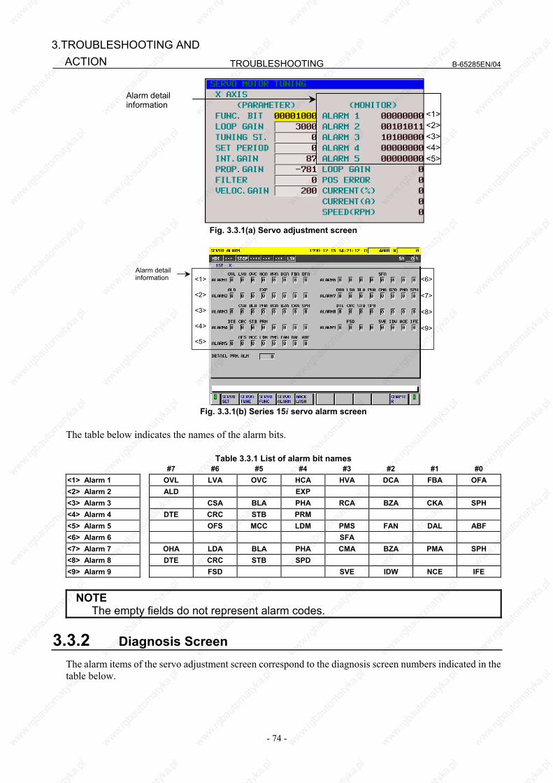
TROUBLESHOOTING B-65285EN/04
- 74 -
3.TROUBLESHOOTING AND ACTION
Alarm detailinformation
<1><2><3><4><5>
Fig. 3.3.1(a) Servo adjustment screen
<1>
<2>
<3>
<4>
<5>
<6>
<7>
<8>
<9>
Alarm detailinformation
Fig. 3.3.1(b) Series 15i servo alarm screen
The table below indicates the names of the alarm bits.
Table 3.3.1 List of alarm bit names #7 #6 #5 #4 #3 #2 #1 #0
<1> Alarm 1 OVL LVA OVC HCA HVA DCA FBA OFA <2> Alarm 2 ALD EXP <3> Alarm 3 CSA BLA PHA RCA BZA CKA SPH <4> Alarm 4 DTE CRC STB PRM <5> Alarm 5 OFS MCC LDM PMS FAN DAL ABF <6> Alarm 6 SFA <7> Alarm 7 OHA LDA BLA PHA CMA BZA PMA SPH <8> Alarm 8 DTE CRC STB SPD <9> Alarm 9 FSD SVE IDW NCE IFE
NOTE The empty fields do not represent alarm codes.
3.3.2 Diagnosis Screen The alarm items of the servo adjustment screen correspond to the diagnosis screen numbers indicated in the table below.

B-65285EN/04 TROUBLESHOOTING
- 75 -
3.TROUBLESHOOTING ANDACTION
Table 3.3.2 Correspondence between the servo adjustment screen and diagnosis screen Alarm No. Series 15i Series 16i, 18i, 21i, 0i
<1> Alarm 1 <2> Alarm 2 <3> Alarm 3 <4> Alarm 4 <5> Alarm 5 <6> Alarm 6 <7> Alarm 7 <8> Alarm 8 <9> Alarm 9
No 3014 + 20(X-1) 3015 + 20(X-1) 3016 + 20(X-1) 3017 + 20(X-1) ⎯⎯⎯⎯⎯ ⎯⎯⎯⎯⎯ ⎯⎯⎯⎯⎯ ⎯⎯⎯⎯⎯ ⎯⎯⎯⎯⎯
No 200 201 202 203 204 ⎯⎯ 205 206 ⎯⎯
<1>
<2>
<3>
<4>
<5>
<7>
<8>
Fig. 3.3.2 Diagnosis screen
3.3.3 Overload Alarm (Soft Thermal, OVC) (Alarm identification method)
#7 #6 #5 #4 #3 #2 #1 #0 <1> Alarm 1 OVL LVA OVC HCA HVA DCA FBA OFA
(Action) (1) Make sure that the motor is not vibrating.
⇒ If a motor vibrates, the current flowing in it becomes more than necessary, resulting in an alarm. (2) Make sure that the power lead to the motor is connected correctly.
⇒ If the connection is incorrect, an abnormal current flows in the motor, resulting in an alarm. (3) Make sure that the following parameters are set correctly.
⇒ An overload alarm is issued based on the result of calculation of these parameters. Be sure to set them to the standard values. For details of the standard values, refer to the FANUC AC SERVO MOTOR αi series Parameter Manual (B-65270EN).
No. 1877 (FS15i) Overload protection coefficient (OVC1) No. 2062 (FS16i)
No. 1878 (FS15i) Overload protection coefficient (OVC2) No. 2063 (FS16i)
No. 1893 (FS15i) Overload protection coefficient (OVCLMT) No. 2065 (FS16i)
No. 1785 (FS15i) Overload protection coefficient (OVC21) No. 2162 (FS16i)
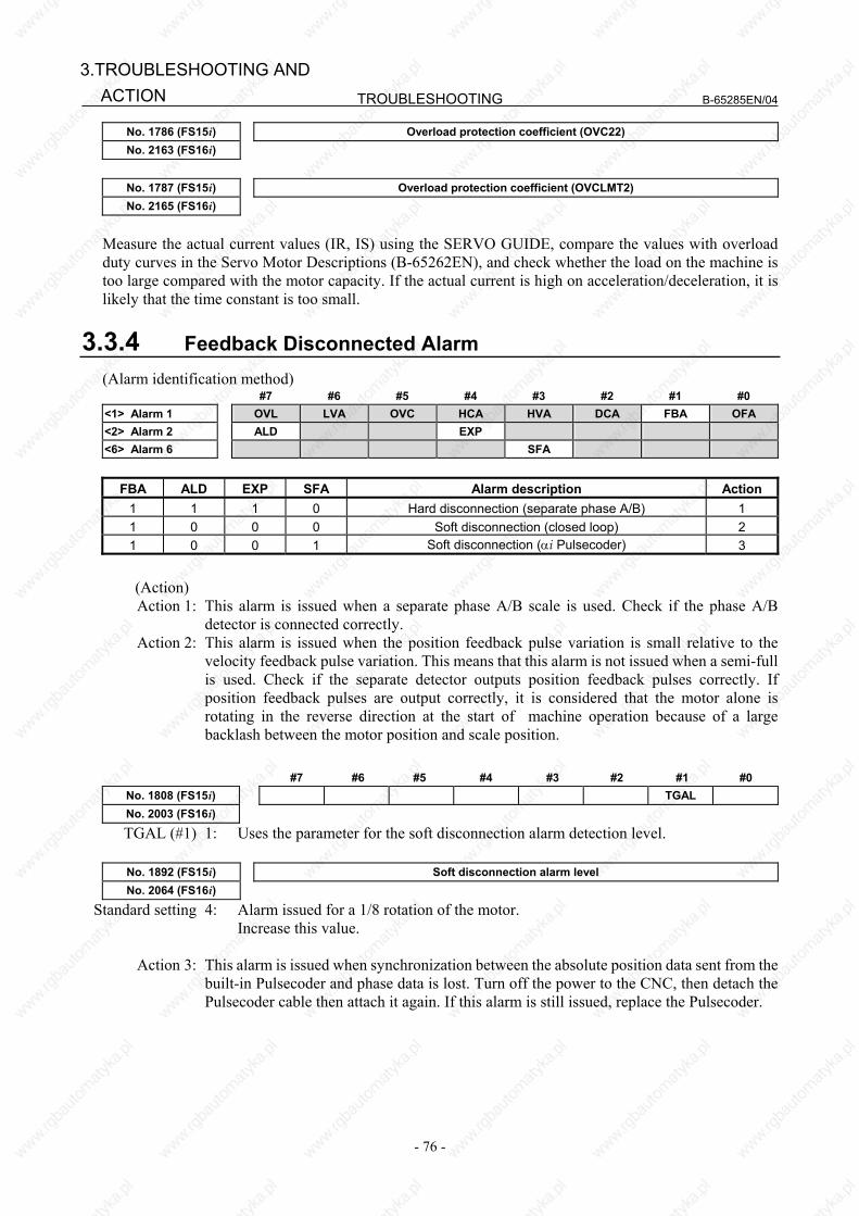
TROUBLESHOOTING B-65285EN/04
- 76 -
3.TROUBLESHOOTING AND ACTION
No. 1786 (FS15i) Overload protection coefficient (OVC22) No. 2163 (FS16i)
No. 1787 (FS15i) Overload protection coefficient (OVCLMT2) No. 2165 (FS16i)
Measure the actual current values (IR, IS) using the SERVO GUIDE, compare the values with overload duty curves in the Servo Motor Descriptions (B-65262EN), and check whether the load on the machine is too large compared with the motor capacity. If the actual current is high on acceleration/deceleration, it is likely that the time constant is too small.
3.3.4 Feedback Disconnected Alarm (Alarm identification method)
#7 #6 #5 #4 #3 #2 #1 #0 <1> Alarm 1 OVL LVA OVC HCA HVA DCA FBA OFA <2> Alarm 2 ALD EXP <6> Alarm 6 SFA
FBA ALD EXP SFA Alarm description Action
1 1 1 0 Hard disconnection (separate phase A/B) 1 1 0 0 0 Soft disconnection (closed loop) 2 1 0 0 1 Soft disconnection (αi Pulsecoder) 3
(Action)
Action 1: This alarm is issued when a separate phase A/B scale is used. Check if the phase A/B detector is connected correctly.
Action 2: This alarm is issued when the position feedback pulse variation is small relative to the velocity feedback pulse variation. This means that this alarm is not issued when a semi-full is used. Check if the separate detector outputs position feedback pulses correctly. If position feedback pulses are output correctly, it is considered that the motor alone is rotating in the reverse direction at the start of machine operation because of a large backlash between the motor position and scale position.
#7 #6 #5 #4 #3 #2 #1 #0
No. 1808 (FS15i) TGAL No. 2003 (FS16i)
TGAL (#1) 1: Uses the parameter for the soft disconnection alarm detection level.
No. 1892 (FS15i) Soft disconnection alarm level No. 2064 (FS16i)
Standard setting 4: Alarm issued for a 1/8 rotation of the motor. Increase this value.
Action 3: This alarm is issued when synchronization between the absolute position data sent from the
built-in Pulsecoder and phase data is lost. Turn off the power to the CNC, then detach the Pulsecoder cable then attach it again. If this alarm is still issued, replace the Pulsecoder.

B-65285EN/04 TROUBLESHOOTING
- 77 -
3.TROUBLESHOOTING ANDACTION
3.3.5 Overheat Alarm (Alarm identification method)
#7 #6 #5 #4 #3 #2 #1 #0 <1> Alarm 1 OVL LVA OVC HCA HVA DCA FBA OFA <2> Alarm 2 ALD EXP
OVL ALD EXP Alarm description Action 1 1 0 Motor overheat 1 1 0 0 Amplifier overheat 1
(Action) (1) Motor overheat First, check whether the motor temperature is high immediately after the alarm is issued. If the alarm is
issued when the motor temperature is not high, the temperature detection circuit may be abnormal. Contact your FANUC service staff.
When the motor temperature is high immediately after the alarm is issued, check the following items: (a) Check the cooling state of the motor.
<1> If the cooling state is abnormal, for example, when the cooling fan stops, check the power specification (voltage, phase sequence, and so on) of the cooling fan. If there is no problem with the power specification, replace the fan unit.
<2> When a liquid-cooled motor is used, check the cooling system. <3> When the motor ambient temperature is higher than the specified temperature, lower the
ambient temperature to satisfy the specification. (b) Increase the time constant or stop time in the program to ease the cutting conditions. Motor temperature information is displayed on the diagnosis screen. Motor temperature: Diagnosis information No. 308 (Series 16i, 30i, and others), diagnosis
information No. 3520 (Series 15i) Pulsecoder temperature: Diagnosis information No. 309 (Series 16i, 30i, and others), diagnosis
information No. 3521 (Series 15i) If an overheat alarm is issued when the temperature is not high, contact your FANUC service
staff. (2) Amplifier overheat See the description about inverter overheat in Subsection 3.2.4.
3.3.6 Invalid Servo Parameter Setting Alarm The invalid servo parameter setting alarm is issued when a setting out of the specifiable range is specified, or an overflow has occurred in an internal calculation. When an invalid parameter is detected on the servo side, alarm 4 #4 (PRM) = 1 results. (Alarm identification method) #7 #6 #5 #4 #3 #2 #1 #0 <4> Alarm 4 DTE CRC STB PRM
For details and action required when the invalid servo parameter setting alarm is issued on the servo side, refer to the FANUC AC SERVO MOTOR αi series Parameter Manual (B-65270EN). (Reference information) Method of checking details of an invalid parameter detected on the servo side (For Series 15i) A number is indicated in the item "Details of invalid parameter" on the servo alarm screen (Fig.
3.3.1(b)).
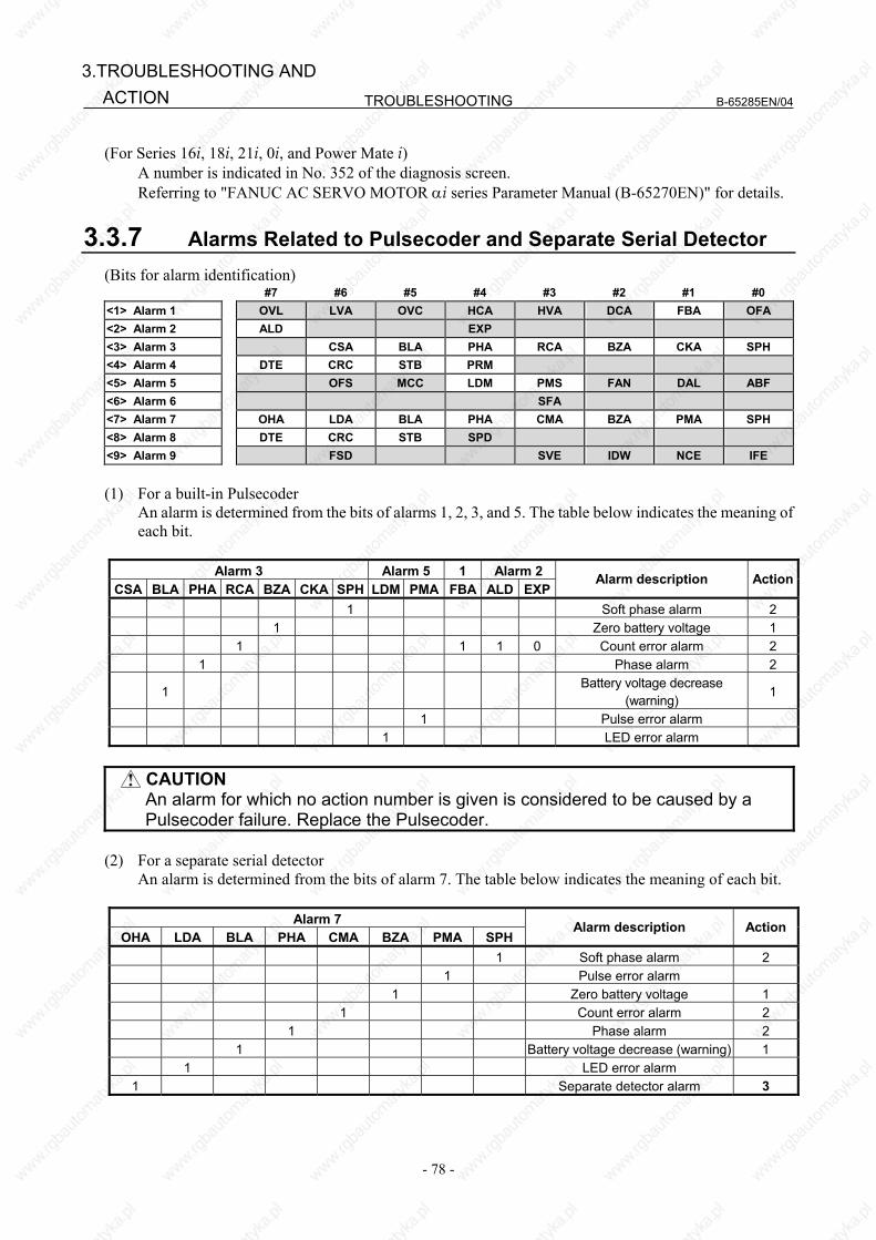
TROUBLESHOOTING B-65285EN/04
- 78 -
3.TROUBLESHOOTING AND ACTION
(For Series 16i, 18i, 21i, 0i, and Power Mate i) A number is indicated in No. 352 of the diagnosis screen. Referring to "FANUC AC SERVO MOTOR αi series Parameter Manual (B-65270EN)" for details.
3.3.7 Alarms Related to Pulsecoder and Separate Serial Detector (Bits for alarm identification)
#7 #6 #5 #4 #3 #2 #1 #0 <1> Alarm 1 OVL LVA OVC HCA HVA DCA FBA OFA <2> Alarm 2 ALD EXP <3> Alarm 3 CSA BLA PHA RCA BZA CKA SPH <4> Alarm 4 DTE CRC STB PRM <5> Alarm 5 OFS MCC LDM PMS FAN DAL ABF <6> Alarm 6 SFA <7> Alarm 7 OHA LDA BLA PHA CMA BZA PMA SPH <8> Alarm 8 DTE CRC STB SPD <9> Alarm 9 FSD SVE IDW NCE IFE
(1) For a built-in Pulsecoder An alarm is determined from the bits of alarms 1, 2, 3, and 5. The table below indicates the meaning of
each bit.
Alarm 3 Alarm 5 1 Alarm 2CSA BLA PHA RCA BZA CKA SPH LDM PMA FBA ALD EXP
Alarm description Action
1 Soft phase alarm 2 1 Zero battery voltage 1 1 1 1 0 Count error alarm 2 1 Phase alarm 2
1 Battery voltage decrease
(warning) 1
1 Pulse error alarm 1 LED error alarm
CAUTION
An alarm for which no action number is given is considered to be caused by a Pulsecoder failure. Replace the Pulsecoder.
(2) For a separate serial detector An alarm is determined from the bits of alarm 7. The table below indicates the meaning of each bit.
Alarm 7
OHA LDA BLA PHA CMA BZA PMA SPHAlarm description Action
1 Soft phase alarm 2 1 Pulse error alarm 1 Zero battery voltage 1 1 Count error alarm 2 1 Phase alarm 2 1 Battery voltage decrease (warning) 1 1 LED error alarm
1 Separate detector alarm 3

B-65285EN/04 TROUBLESHOOTING
- 79 -
3.TROUBLESHOOTING ANDACTION
CAUTION An alarm for which no action number is given is considered to be caused by a
detector failure. Replace the detector.
(Action) Action 1: Battery-related alarms Check if a battery is connected. When the power is turned on for the first time after a battery
is connected, the zero battery voltage alarm is issued. In such a case, turn off the power, then turn on the power again. If the alarm is still issued, check the battery voltage. If the battery voltage decrease alarm is issued, check the voltage, and replace the battery as required.
Action 2: Alarms that may be issued for noise If an alarm is issued intermittently or after emergency stop cancellation, noise is probably
the cause. So, provide noise protection. If the same alarm is still issued after noise protection is provided, replace the detector.
Action 3: Alarm condition detected by the separate detector If the separate detector detects an alarm condition, contact the manufacturer of the detector
for information on troubleshooting. (3) Alarms related to serial communication An alarm is determined from the bits of alarms 4 and 8.
Alarm 4 Alarm 8 DTE CRC STB DTE CRC STB
Alarm description
1 1 1
Serial Pulsecoder communication alarm
1 1 1
Separate serial Pulsecoder communication alarm
Action: Serial communication is not performed correctly. Check if the cable is connected correctly
and is not broken. If CRC or STB is issued, noise may be the cause. So, provide noise protection. If CRC or STB is always issued after the power is turned on, the Pulsecoder or amplifier control board or the pulse module may be faulty.
3.3.8 Other Alarms (Alarm identification method)
#7 #6 #5 #4 #3 #2 #1 #0 <5> Alarm 5 OFS MCC LDM PMS FAN DAL ABF
OFS DAL ABF Alarm description Action
1 Feedback mismatch alarm 1 1 Excessive semi-full error alarm 2 1 Current offset error alarm 3
(Action)
Action 1: This alarm is issued when the move direction of the position detector is opposite to the move direction of the speed detector. Check the rotation direction of the separate detector. If the rotation direction of the separate detector is opposite to the rotation direction of the motor, take the following action:
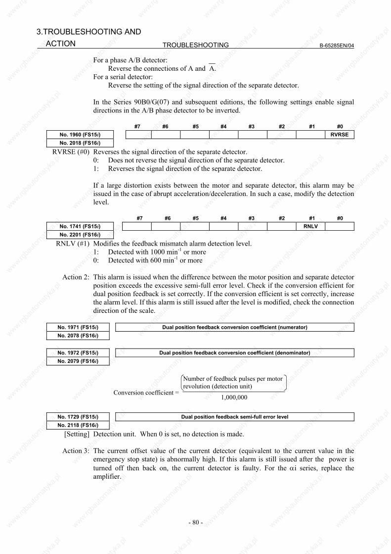
TROUBLESHOOTING B-65285EN/04
- 80 -
3.TROUBLESHOOTING AND ACTION
For a phase A/B detector: Reverse the connections of A and A. For a serial detector: Reverse the setting of the signal direction of the separate detector. In the Series 90B0/G(07) and subsequent editions, the following settings enable signal
directions in the A/B phase detector to be inverted.
#7 #6 #5 #4 #3 #2 #1 #0 No. 1960 (FS15i) RVRSENo. 2018 (FS16i)
RVRSE (#0) Reverses the signal direction of the separate detector. 0: Does not reverse the signal direction of the separate detector. 1: Reverses the signal direction of the separate detector. If a large distortion exists between the motor and separate detector, this alarm may be issued in the case of abrupt acceleration/deceleration. In such a case, modify the detection level.
#7 #6 #5 #4 #3 #2 #1 #0
No. 1741 (FS15i) RNLV No. 2201 (FS16i)
RNLV (#1) Modifies the feedback mismatch alarm detection level. 1: Detected with 1000 min-1 or more 0: Detected with 600 min-1 or more
Action 2: This alarm is issued when the difference between the motor position and separate detector position exceeds the excessive semi-full error level. Check if the conversion efficient for dual position feedback is set correctly. If the conversion efficient is set correctly, increase the alarm level. If this alarm is still issued after the level is modified, check the connection direction of the scale.
No. 1971 (FS15i) Dual position feedback conversion coefficient (numerator) No. 2078 (FS16i)
No. 1972 (FS15i) Dual position feedback conversion coefficient (denominator) No. 2079 (FS16i)
Conversion coefficient =
Number of feedback pulses per motorrevolution (detection unit)
1,000,000
No. 1729 (FS15i) Dual position feedback semi-full error level No. 2118 (FS16i)
[Setting] Detection unit. When 0 is set, no detection is made.
Action 3: The current offset value of the current detector (equivalent to the current value in the emergency stop state) is abnormally high. If this alarm is still issued after the power is turned off then back on, the current detector is faulty. For the αi series, replace the amplifier.
B-65285EN/04 TROUBLESHOOTING
- 81 -
3.TROUBLESHOOTING ANDACTION
3.4 SPINDLE AMPLIFIER If an alarm occurs in the Spindle Amplifier, the ALM LED lights red in the STATUS display, and the two-digit 7-segment LEDs indicate the alarm code.
The ALM LEDlights red.
Alarm code 01, 02 or above is indicated.status
3.4.1 Alarm Code 01 The inside temperature of the motor is higher than the specified temperature. (1) If this alarm is issued during cutting (the motor temperature is high)
(a) Check the cooling state of the motor. <1> If the cooling fan of the spindle motor is stopped, check the power supply of the cooling fan.
If the cooling fan is still inoperative, replace it with a new one. <2> When a liquid-cooled motor is used, check the cooling system. <3> When the ambient temperature of the spindle motor is higher than the specified temperature,
lower the ambient temperature to satisfy the specification. (b) Recheck the cutting conditions.
(2) If this alarm is issued under a light load (the motor temperature is high) (a) When the frequency of acceleration/deceleration is too high Set such a use condition that the average including output at acceleration/deceleration does not
exceed the continuous rating. (b) The parameters specific to the motor are not correctly. Referring to "FANUC AC SPINDLE MOTOR αi series Parameter Manual (B-65280EN),"
check the motor-specific parameters. (3) If this alarm is issued when the motor temperature is low
(a) The spindle motor feedback cable is faulty. Replace the cable. (b) The parameters specific to the motor are not set correctly. Referring to "FANUC AC SPINDLE MOTOR αi series Parameter Manual (B-65280EN),"
check the motor-specific parameters.
FS15i FS16i FS0i-B/C
FS30i FS0i-D
For α series motor For αi series motor
3134 4134 4134 0 Motor-specific parameter (c) The control printed circuit board is faulty. Replace the control printed circuit board or spindle amplifier. (d) The motor (internal thermostat) is faulty. Replace the motor.
3.4.2 Alarm Code 02 The actual motor speed is largely deviated from the commanded speed. (1) If this alarm is issued during motor acceleration
(a) The parameter setting of acceleration/deceleration time is incorrect. Set the following parameter with the actual acceleration/deceleration time for your machine plus
some margin.
TROUBLESHOOTING B-65285EN/04
- 82 -
3.TROUBLESHOOTING AND ACTION
FS15i FS16i FS0i-B/C
FS30i FS0i-D Description
3082 4082 4082 Setting of acceleration/deceleration time (b) The parameter for the speed detector is not set correctly. Referring to "FANUC AC SPINDLE MOTOR αi series Parameter Manual (B-65280EN)," set a
correct value.
(2) If this alarm is issued at a heavy cutting load (a) The cutting load has exceeded the motor output power. Check the load meter indication, and review the use condition. (b) The parameters for output restriction are not set correctly. Check that the settings of the following parameters satisfy the machine and motor specifications:
FS15i FS16i FS0i-B/C
FS30i FS0i-D Description
3028 4028 4028 Output restriction pattern setting 3029 4029 4029 Output restriction value
(c) The parameters specific to the motor are not correctly. Referring to "FANUC AC SPINDLE MOTOR αi series Parameter Manual (B-65280EN),"
check the motor-specific parameters.
3.4.3 Alarm Code 03 The fuse of the DC link has blown. (The voltage at the DC link is insufficient.) This alarm is checked when emergency stop is cancelled. (1) If this alarm is issued during spindle operation (rotation) The fuse of the DC link inside the Spindle Amplifier has probably blown. So, replace the Spindle
Amplifier. This alarm may be caused by the following: <1> Power lead short-circuited to ground <2> Motor winding short-circuited to ground <3> IGBT or IPM module failure
(2) If the Power Supply input magnetic contactor is once turned on and is turned off with this alarm when emergency stop is cancelled or the CNC is started (When two spindles are connected, the magnetic contactor may not be turned off.) (a) The DC link wire is not connected. Check the DC link wiring for errors. (b) The fuse of the DC link inside the Spindle Amplifier has blown. Replace the Spindle Amplifier.
3.4.4 Alarm Code 06 The temperature sensor is abnormal, or the temperature sensor cable is broken. (1) The parameters specific to the motor are not correctly. Referring to "FANUC AC SPINDLE MOTOR αi series Parameter Manual (B-65280EN)," check the
motor-specific parameters. (2) Cable is faulty. Feedback cable is faulty. Replace the cable. (3) The control printed-circuit board is faulty. Replace the control printed-circuit board or spindle amplifier. (4) A thermo sensor is faulty. Replace the motor (thermo sensor).

B-65285EN/04 TROUBLESHOOTING
- 83 -
3.TROUBLESHOOTING ANDACTION
3.4.5 Alarm Code 07 The motor rotates at a speed exceeding 115% (standard setting) of the maximum allowable speed. (1) If this alarm is issued during spindle synchronization If one of the motors operating in spindle synchronization is deactivated (SFR or SRV) and activated
again, the spindle motor may accelerate to its maximum rotation speed in order to eliminate the position error accumulated while the motor is off, resulting in this alarm being issued.
Modify the ladder in such a way that this sequence will not be used. (2) Spindle Amplifier is faulty. Replace the Spindle Amplifier.
3.4.6 Alarm Code 09 The temperature of the heat sink of the Spindle Amplifier main circuit has risen abnormally. This alarm is issued for αi SP22, αi SP30HV and later. With αi SP2.2 to αi SP15 and αi SP5.5HV to αi SP15HV, however, Alarm 12 is issued for the same cause. (1) If this alarm is issued during cutting (the heat sink temperature is high)
(a) If this alarm is issued when the load meter reads a value below the continuous rating of the amplifier, check the cooling state of the heat sink. <1> If the cooling fan is stopped, check the power supply (connector CX1A/B). If the cooling
fan is still inoperative, replace the Spindle Amplifier with a new one. <2> When the ambient temperature is higher than the specified temperature, lower the ambient
temperature to satisfy the specification. (b) When this alarm is issued because the load meter reads a value above the continuous rating of the
amplifier, improve the use method. (c) When the heat sink on the back of the amplifier is too dirty, clean the heat sink, for example, by
blowing air. Consider the use of a structure that prevents the heat sink from being directly exposed to coolant.
(2) If this alarm is issued under a light load (the heat sink temperature is high) (a) When the frequency of acceleration/deceleration is too high Set such a use condition that the average including output at acceleration/deceleration does not
exceed the continuous rating. (b) The parameters specific to the motor are not set correctly. Referring to "FANUC AC SPINDLE MOTOR αi series Parameter Manual (B-65280EN),"
check the motor-specific parameters. (3) Poor installation of the control printed-circuit board Be sure to push the faceplate as far as it will go. (This alarm may be displayed if one of the connectors
for connection between the control printed-circuit board and power printed-circuit board is detached.) (4) If this alarm is issued when the heat sink temperature is low Replace the Spindle Amplifier.
3.4.7 Alarm Code 10 The control power supply voltage decreases. Troubleshooting when this alarm is issued The control power supply, power cable, Power Supply, or Spindle Amplifier is defective. Replace the control power supply, power cable, Power Supply, or Spindle Amplifier.
TROUBLESHOOTING B-65285EN/04
- 84 -
3.TROUBLESHOOTING AND ACTION
3.4.8 Alarm Code 12 An excessively large current flowed into the DC link of the main circuit. With αi SP2.2 to αi SP15 and αi SP5.5HV to αi SP15HV, this alarm indicates that the power module (IPM) of the main circuit detected an error such as an excessive load, overcurrent. (1) If this alarm is issued on αi SP2.2 to αi SP1 and αi SP5.5HV to αi SP15HV Check alarm code 09 as well. (2) Poor installation of the control printed-circuit board Be sure to push the faceplate as far as it will go. (This alarm may be displayed if one of the connectors
for connection between the control printed-circuit board and power printed-circuit board is detached.) (3) If this alarm is issued immediately after a spindle rotation command is specified
(a) The motor power lead is faulty. Check for a short circuit between motor power leads and short-circuit to ground, and replace the
power lead as required. (b) The motor winding has an insulation failure. If the motor is short-circuited to ground, replace the motor. (c) The parameters specific to the motor are not set correctly. Referring to "FANUC AC SPINDLE MOTOR αi series Parameter Manual (B-65280EN),"
check the motor-specific parameters. (d) The Spindle Amplifier is faulty. A power element (IGBT, IPM) may be destroyed. Replace the Spindle Amplifier.
(4) If this alarm is issued during spindle rotation (a) A power element is destroyed. A power element (IGBT, IPM) may be destroyed. Replace the Spindle Amplifier. If the amplifier setting condition is not satisfied, or cooling is insufficient because the heat sink is
dirty, the power elements may be destroyed. When the heat sink on the back of the amplifier is too dirty, clean the heat sink, for example, by
blowing air. Consider the use of a structure that prevents the heat sink from being directly exposed to coolant.
For the installation condition, refer to "FANUC SERVO AMPLIFIER αi series Descriptions (B-65282EN)."
(b) The parameters specific to the motor are not set correctly. Referring to "FANUC AC SPINDLE MOTOR αi series Parameter Manual (B-65280EN),"
check the parameters specific to the motor. (c) Speed sensor signal error Check the spindle sensor signal waveform. If an error is found, make an adjustment or replace the
sensor as required.
3.4.9 Alarm Code 13 An error was detected in the CPU internal RAM. Troubleshooting when this alarm is issued The Spindle Amplifier is abnormal. Replace the Spindle Amplifier.
3.4.10 Alarm Code 14 Amplifier ID data inconsistent with series and edition of software was detected. Troubleshooting when this alarm is issued The Spindle Amplifier is abnormal. Replace the Spindle Amplifier.
B-65285EN/04 TROUBLESHOOTING
- 85 -
3.TROUBLESHOOTING ANDACTION
3.4.11 Alarm Code 15 In output switching control or spindle switching control, the switching operation sequence was not executed correctly. This alarm is issued if one second or more elapses from the transition of a switch request signal (SPSL or RSL) until a power lead state check signal (MCFN, MFNHG, RCH, or RCHHG) makes a transition. (1) Troubleshooting when this alarm is issued
(a) The magnetic contactor (switch unit) for power lead switching is faulty. If the contact is inoperative, check the power supply of the magnetic contactor. If the magnetic
contactor is still inoperative, replace the magnetic contactor. (b) The I/O unit or wiring for checking the contact of the magnetic contactor is faulty. If a defect is found in the I/O unit or wiring, replace the I/O unit or wiring. (c) The sequence (ladder) is incorrect. Modify the sequence so that switching is completed within 1 second.
3.4.12 Alarm Code 16 An error was found in a CPU internal RAM test by the Dual Check Safety function. Troubleshooting when this alarm is issued The Spindle Amplifier is abnormal. Replace the Spindle Amplifier.
3.4.13 Alarm Code 17 An error was detected in amplifier ID data. Troubleshooting when this alarm is issued The Spindle Amplifier control printed-circuit board becomes loose or the Spindle Amplifier is
abnormal. Check whether the Spindle Amplifier control printed-circuit board is mounted correctly. When the board is mounted correctly, replace the Spindle Amplifier.
3.4.14 Alarm Code 18 A sum check is abnormal. If this alarm is issued, replace the Spindle Amplifier or Spindle Amplifier control printed-circuit board.
3.4.15 Alarm Codes 19 and 20 The offset voltage of the phase U (alarm code 19) or phase V (alarm code 20) current detection circuit is excessively high. A check is made when the power is turned on. If this alarm is issued, replace the Spindle Amplifier. If this alarm is issued immediately after the Spindle Amplifier control printed circuit board is replaced, check the plugging of the connectors between the power unit and Spindle Amplifier control printed circuit board.

TROUBLESHOOTING B-65285EN/04
- 86 -
3.TROUBLESHOOTING AND ACTION
3.4.16 Alarm Code 21 The specified polarity of the position sensor is incorrect. Troubleshooting when this alarm is issued
(a) Check the position sensor polarity parameter (bit 4 of parameter No. 4001). (b) Check the feedback cable of the position sensor.
3.4.17 Alarm Code 22 Overcurrent exceeding the time rating of the Spindle Amplifier flowed. Possible causes are a high frequency of acceleration/deceleration and high cutting load. Troubleshooting when this alarm is issued Ease the operation conditions.
3.4.18 Alarm Code 24 Serial communication data transferred between the CNC and Spindle Amplifier contains an error. (Note) Troubleshooting when this alarm is issued
(a) Noise occurring between the CNC and Spindle Amplifier (connected via an electric cable) caused an error in communication data.
Check the condition for maximum wiring length. Referring to "Connection," in "FANUC SERVO AMPLIFIER αi series Descriptions
(B-65282EN)," check the condition of electric cable connection. (b) Noise exercises an influence because a communication cable is bundled with the power lead. If a communication cable is bundled with the power lead for the motor, separate them from each
other. (c) A cable is faulty. Replace the cable. If an optical I/O link adapter is used, the optical link adapter or optical cable may be faulty. (d) The Spindle Amplifier is faulty. Replace the Spindle Amplifier or Spindle Amplifier control printed circuit board. (e) The CNC is faulty. Replace the board or module related to the serial spindle.
NOTE This alarm is issued also if the CNC power is off. This is not a failure, though.
3.4.19 Alarm Code 27 The signal of the αi position coder is disconnected. (1) If this alarm is issued when the motor is deactivated
(a) The setting of a parameter is incorrect. Referring to "FANUC AC SPINDLE MOTOR αi series Parameter Manual (B-65280EN),"
check the parameter for sensor setting. (b) The cable is disconnected. If the connection of the feedback cable is correct, replace the cable. (c) The Spindle Amplifier is faulty. Replace the Spindle Amplifier or Spindle Amplifier control printed circuit board.
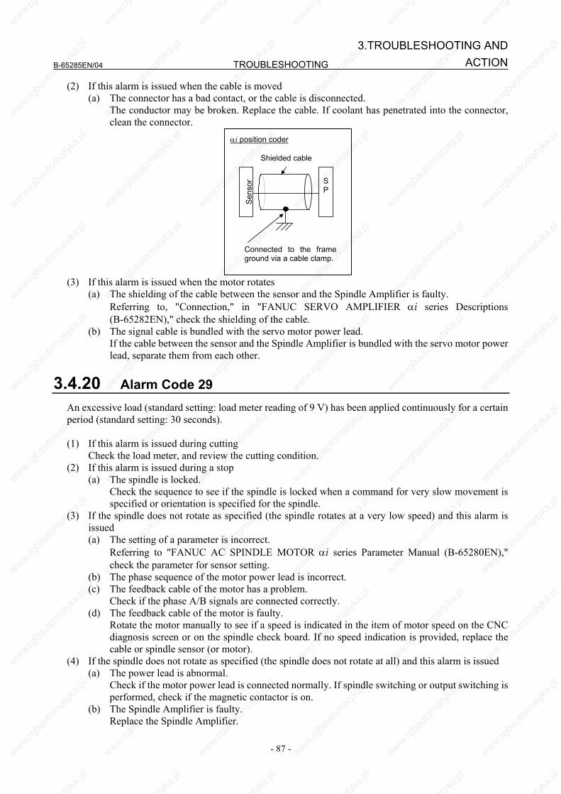
B-65285EN/04 TROUBLESHOOTING
- 87 -
3.TROUBLESHOOTING ANDACTION
(2) If this alarm is issued when the cable is moved (a) The connector has a bad contact, or the cable is disconnected. The conductor may be broken. Replace the cable. If coolant has penetrated into the connector,
clean the connector.
SP
Sen
sor
Connected to the frameground via a cable clamp.
Shielded cable
αi position coder
(3) If this alarm is issued when the motor rotates
(a) The shielding of the cable between the sensor and the Spindle Amplifier is faulty. Referring to, "Connection," in "FANUC SERVO AMPLIFIER αi series Descriptions
(B-65282EN)," check the shielding of the cable. (b) The signal cable is bundled with the servo motor power lead. If the cable between the sensor and the Spindle Amplifier is bundled with the servo motor power
lead, separate them from each other.
3.4.20 Alarm Code 29 An excessive load (standard setting: load meter reading of 9 V) has been applied continuously for a certain period (standard setting: 30 seconds). (1) If this alarm is issued during cutting Check the load meter, and review the cutting condition. (2) If this alarm is issued during a stop
(a) The spindle is locked. Check the sequence to see if the spindle is locked when a command for very slow movement is
specified or orientation is specified for the spindle. (3) If the spindle does not rotate as specified (the spindle rotates at a very low speed) and this alarm is
issued (a) The setting of a parameter is incorrect. Referring to "FANUC AC SPINDLE MOTOR αi series Parameter Manual (B-65280EN),"
check the parameter for sensor setting. (b) The phase sequence of the motor power lead is incorrect. (c) The feedback cable of the motor has a problem. Check if the phase A/B signals are connected correctly. (d) The feedback cable of the motor is faulty. Rotate the motor manually to see if a speed is indicated in the item of motor speed on the CNC
diagnosis screen or on the spindle check board. If no speed indication is provided, replace the cable or spindle sensor (or motor).
(4) If the spindle does not rotate as specified (the spindle does not rotate at all) and this alarm is issued (a) The power lead is abnormal. Check if the motor power lead is connected normally. If spindle switching or output switching is
performed, check if the magnetic contactor is on. (b) The Spindle Amplifier is faulty. Replace the Spindle Amplifier.

TROUBLESHOOTING B-65285EN/04
- 88 -
3.TROUBLESHOOTING AND ACTION
3.4.21 Alarm Code 31 The motor failed to rotate as specified, and has stopped or is rotating at a very low speed. (1) If the motor rotates at a very low speed and this alarm is issued
(a) The setting of a parameter is incorrect. Referring to "FANUC AC SPINDLE MOTOR αi series Parameter Manual (B-65280EN),"
check the parameter for sensor setting. (b) The phase sequence of the motor power lead is incorrect. Check whether the phase sequence of the motor power lead is correct. (c) The feedback cable of the motor has a problem. Check if the phase A/B signals are connected correctly. (d) The feedback cable of the motor is faulty. Rotate the motor manually to see if a speed is indicated in the item of motor speed on the CNC
diagnosis screen or on the spindle check board. If no speed indication is provided, replace the cable or spindle sensor (or motor).
(2) If the motor does not rotate at all and this alarm is issued (a) The sequence for locking the spindle is incorrect. Check the sequence to see if the spindle is locked. (b) The power lead is faulty. Check if the power lead is connected to the motor correctly. If spindle switching or winding
switching is performed, check if the magnetic contactor is on. (c) The Spindle Amplifier is faulty. Replace the Spindle Amplifier.
3.4.22 Alarm Code 32 LSI memory for serial communication is abnormal. A check is made when the power is turned on. If this alarm is issued, replace the Spindle Amplifier or Spindle Amplifier control printed circuit board.
3.4.23 Alarm Code 34 Parameter data outside the specifiable range was set. Troubleshooting when this alarm is issued Connect the spindle check board. The spindle check board displays "AL-34" and "F-xxx" alternately. "F-xxx" indicates a parameter
number outside the specifiable range. For the correspondence between the CNC parameter numbers and "F-xxx," refer to "FANUC AC SPINDLE MOTOR αi series Parameter Manual (B-65280EN)."
3.4.24 Alarm Code 36 The error counter overflowed. (1) The setting of a parameter is incorrect.
(a) The gear ratio set in a parameter is incorrect. Check if an excessively large gear ratio is set. (b) The setting of a position gain is incorrect. If the gear ratio data is correct, increase the position gain.
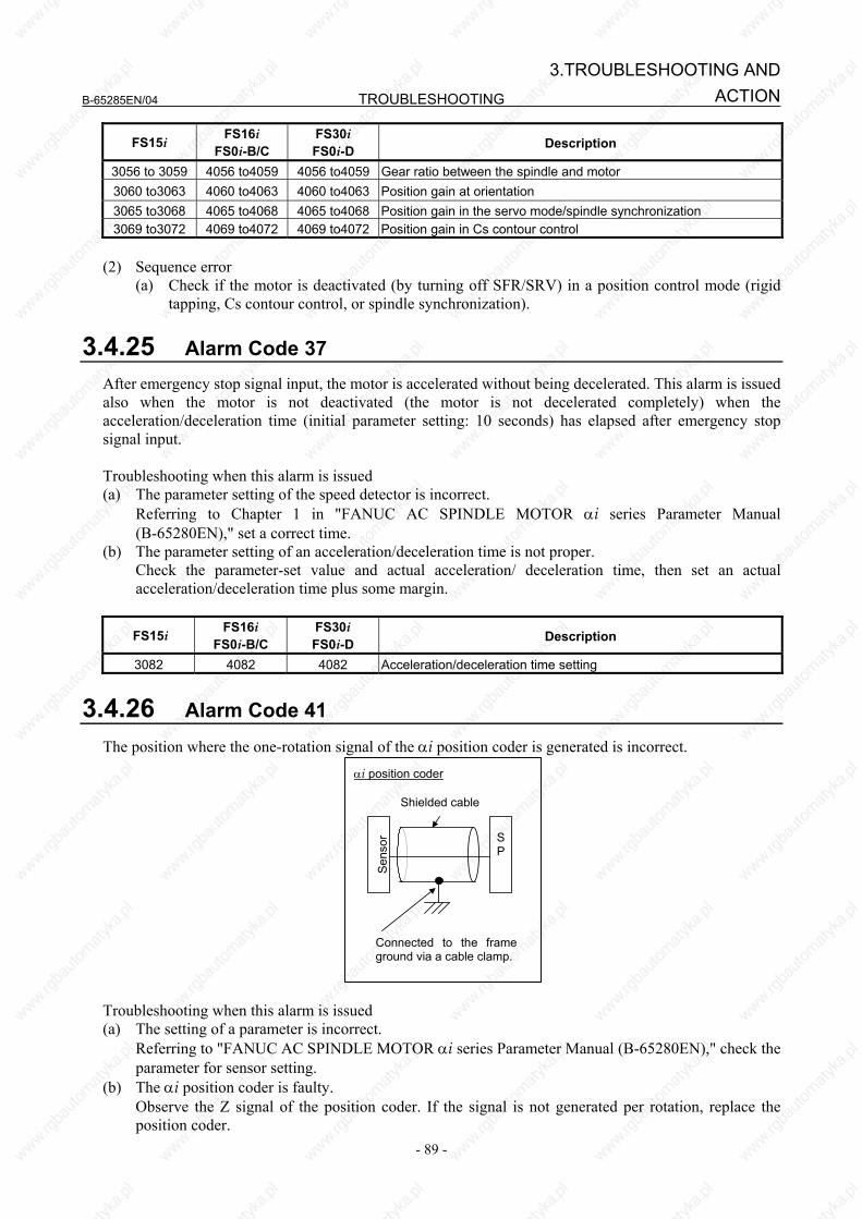
B-65285EN/04 TROUBLESHOOTING
- 89 -
3.TROUBLESHOOTING ANDACTION
FS15i FS16i FS0i-B/C
FS30i FS0i-D Description
3056 to 3059 4056 to4059 4056 to4059 Gear ratio between the spindle and motor 3060 to3063 4060 to4063 4060 to4063 Position gain at orientation 3065 to3068 4065 to4068 4065 to4068 Position gain in the servo mode/spindle synchronization 3069 to3072 4069 to4072 4069 to4072 Position gain in Cs contour control
(2) Sequence error
(a) Check if the motor is deactivated (by turning off SFR/SRV) in a position control mode (rigid tapping, Cs contour control, or spindle synchronization).
3.4.25 Alarm Code 37 After emergency stop signal input, the motor is accelerated without being decelerated. This alarm is issued also when the motor is not deactivated (the motor is not decelerated completely) when the acceleration/deceleration time (initial parameter setting: 10 seconds) has elapsed after emergency stop signal input. Troubleshooting when this alarm is issued (a) The parameter setting of the speed detector is incorrect. Referring to Chapter 1 in "FANUC AC SPINDLE MOTOR αi series Parameter Manual
(B-65280EN)," set a correct time. (b) The parameter setting of an acceleration/deceleration time is not proper. Check the parameter-set value and actual acceleration/ deceleration time, then set an actual
acceleration/deceleration time plus some margin.
FS15i FS16i FS0i-B/C
FS30i FS0i-D Description
3082 4082 4082 Acceleration/deceleration time setting
3.4.26 Alarm Code 41 The position where the one-rotation signal of the αi position coder is generated is incorrect.
SP
Sen
sor
Connected to the frameground via a cable clamp.
Shielded cable
αi position coder
Troubleshooting when this alarm is issued (a) The setting of a parameter is incorrect. Referring to "FANUC AC SPINDLE MOTOR αi series Parameter Manual (B-65280EN)," check the
parameter for sensor setting. (b) The αi position coder is faulty. Observe the Z signal of the position coder. If the signal is not generated per rotation, replace the
position coder.

TROUBLESHOOTING B-65285EN/04
- 90 -
3.TROUBLESHOOTING AND ACTION
(c) The shielding of the cable between the sensor and Spindle Amplifier is faulty. Referring to "Connection," in "FANUC SERVO AMPLIFIER αi series Descriptions (B-65282EN),"
check the shielding of the cable. (d) The signal cable is bundled with the servo motor power lead. If the cable between the sensor and Spindle Amplifier is bundled with the servo motor power lead,
separate them from each other. (e) The Spindle Amplifier is faulty. Replace the Spindle Amplifier or Spindle Amplifier control printed circuit board.
3.4.27 Alarm Code 42 The one-rotation signal of the αi position coder is not generated. Troubleshooting when this alarm is issued (a) The setting of a parameter is incorrect. Referring to "FANUC AC SPINDLE MOTOR αi series Parameter Manual (B-65280EN)," check the
parameter for sensor setting. (b) The αi position coder is faulty. Check the check pin PSD on the spindle check board. If the signal is not generated per rotation, replace
the connection cable and position coder. (c) The Spindle Amplifier is faulty. Replace the Spindle Amplifier or Spindle Amplifier control printed circuit board.
3.4.28 Alarm Code 43 The position coder signal of the master spindle used in differential spindle speed control is disconnected. For troubleshooting when this alarm is issued, see the subsection about alarm code 27.
3.4.29 Alarm Code 46 The one-rotation signal of the position coder cannot be detected normally during thread cutting. Troubleshoot as in the case of alarm code 41.
3.4.30 Alarm Code 47 The count value of αi position coder signal pulses is abnormal. Phases A and B for the position coder have a feedback pulse count of 4096 p/rev per spindle rotation. The Spindle Amplifier checks the pulse counts of phases A and B equivalent to the position coder each time a one-rotation signal is generated. The alarm is issued when a pulse count beyond the specified range is detected. (1) If this alarm is issued when the cable is moved (as in the case where the spindle moves) The conductor may be broken. Replace the cable. If coolant has penetrated into the connector, clean
the connector. (2) Troubleshooting in other cases
(a) The setting of a parameter is incorrect. Referring to "FANUC AC SPINDLE MOTOR αi series Parameter Manual (B-65280EN),"
check the parameter for sensor setting.
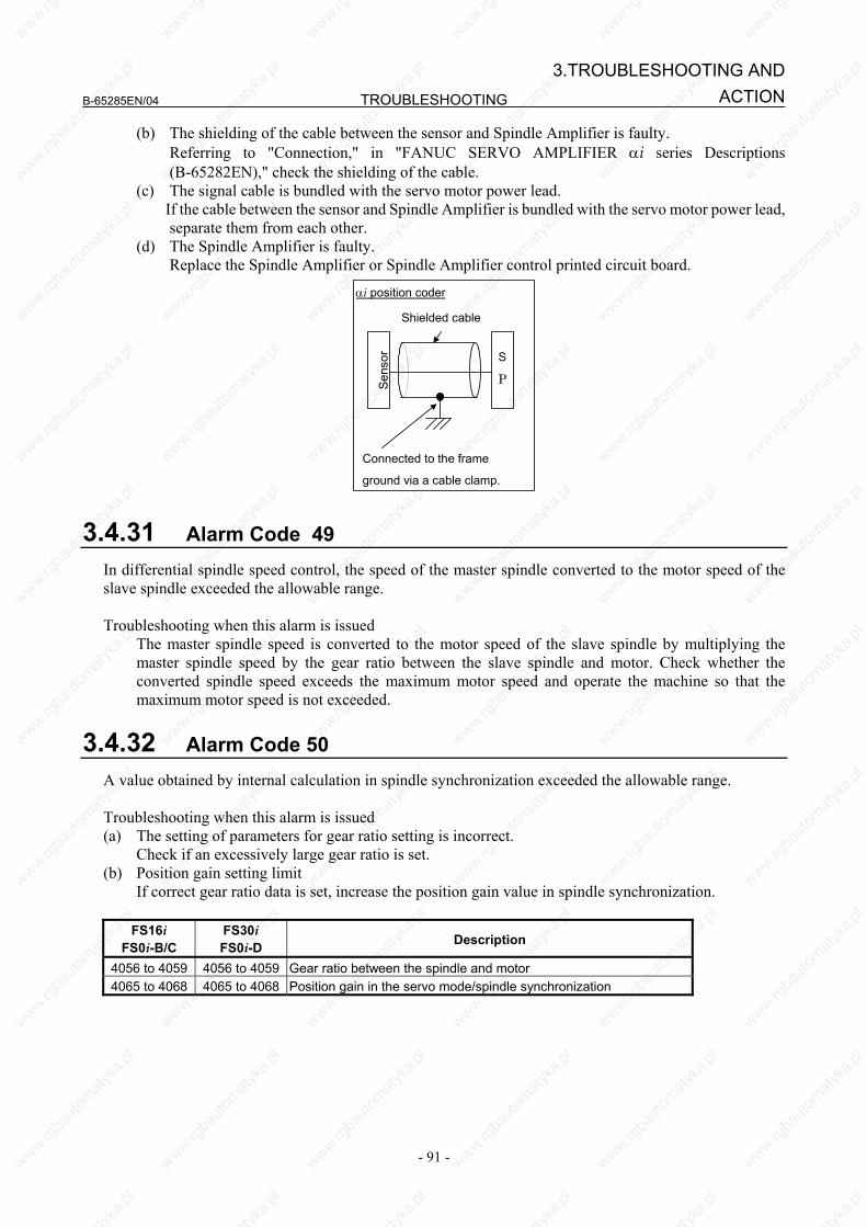
B-65285EN/04 TROUBLESHOOTING
- 91 -
3.TROUBLESHOOTING ANDACTION
(b) The shielding of the cable between the sensor and Spindle Amplifier is faulty. Referring to "Connection," in "FANUC SERVO AMPLIFIER αi series Descriptions
(B-65282EN)," check the shielding of the cable. (c) The signal cable is bundled with the servo motor power lead. If the cable between the sensor and Spindle Amplifier is bundled with the servo motor power lead,
separate them from each other. (d) The Spindle Amplifier is faulty. Replace the Spindle Amplifier or Spindle Amplifier control printed circuit board.
S
PSen
sor
Connected to the frame
ground via a cable clamp.
Shielded cable
αi position coder
3.4.31 Alarm Code 49 In differential spindle speed control, the speed of the master spindle converted to the motor speed of the slave spindle exceeded the allowable range. Troubleshooting when this alarm is issued The master spindle speed is converted to the motor speed of the slave spindle by multiplying the
master spindle speed by the gear ratio between the slave spindle and motor. Check whether the converted spindle speed exceeds the maximum motor speed and operate the machine so that the maximum motor speed is not exceeded.
3.4.32 Alarm Code 50 A value obtained by internal calculation in spindle synchronization exceeded the allowable range. Troubleshooting when this alarm is issued (a) The setting of parameters for gear ratio setting is incorrect. Check if an excessively large gear ratio is set. (b) Position gain setting limit If correct gear ratio data is set, increase the position gain value in spindle synchronization.
FS16i
FS0i-B/C FS30i FS0i-D Description
4056 to 4059 4056 to 4059 Gear ratio between the spindle and motor 4065 to 4068 4065 to 4068 Position gain in the servo mode/spindle synchronization

TROUBLESHOOTING B-65285EN/04
- 92 -
3.TROUBLESHOOTING AND ACTION
3.4.33 Alarm Codes 52 and 53 The synchronization signal (ITP) in communication data transferred to and from the CNC stopped. Troubleshooting when this alarm is issued (a) The Spindle Amplifier is faulty. Replace the Spindle Amplifier or Spindle Amplifier control printed circuit board. (b) The CNC is faulty. Replace the board or module related to the serial spindle.
3.4.34 Alarm Code 54 A large current flowing in the motor for a long time was detected. Troubleshoot as in the case of alarm code 29.
3.4.35 Alarm Code 55 In spindle switching control or output switching control, a mismatch between the switching request signal (SPSL or RSL) and the power lead state check signal (MCFN, MFNHG, RCH, or RCHHG) continues during motor activation. Troubleshooting when this alarm is issued (a) The magnetic contactor (switch unit) for power lead switching is faulty. If the contact is inoperative, check the power supply of the magnetic contactor. If the magnetic
contactor is still inoperative, replace the magnetic contactor. (b) The I/O unit or wiring for checking the contact of the magnetic contactor is faulty. If a defect is found in the I/O unit or wiring, replace the I/O unit or wiring. (c) The sequence (ladder) is incorrect. Modify the sequence so that switching is not performed during activation. For details of the signals,
refer to "FANUC SERVO AMPLIFIER αi series Descriptions (B-65282EN)."
3.4.36 Alarm Code 56 The cooling fan for the control circuit section has stopped. (a) Poor installation of the control printed-circuit board Be sure to push the faceplate as far as it will go. (This alarm may be displayed if one of the connectors
for connection between the control printed-circuit board and power printed-circuit board is detached.) (b) Replace the Spindle Amplifier or its internal cooling fan.
3.4.37 Alarm Code 61 The difference in position between the semi-closed side and closed side exceeded the setting level (parameter No. 4354) for the dual position feedback function. Troubleshooting when this alarm is issued (a) When this alarm is issued at the start of the machine, there may be a setting error in a sensor-related
parameter or motor-end position feedback conversion coefficient parameter. Check whether conversion coefficient parameters Nos. 4171 and 4172 (in high gear) and Nos. 4173
and 4174 (in low gear) are set correctly. Also, refer to the FANUC AC SPINDLE MOTOR ai series Parameter Manual (B-65280EN) to check the settings of the sensor-related parameters.

B-65285EN/04 TROUBLESHOOTING
- 93 -
3.TROUBLESHOOTING ANDACTION
(b) When the conversion coefficients are set correctly, the level set for parameter No. 4354 may be too low.
(c) When this alarm is issued for a system which has been operating normally, there may be slippage between the motor and spindle. Check the machine.
(d) When this alarm is intermittently issued for a system which has been operating normally, a count error may occur in the motor-end or spindle-end position feedback signal due to noise.
3.4.38 Alarm Code 65 A magnetic pole detection error occurred. This spindle alarm is issued for the BiS Series spindle motors (synchronous spindle motors). Troubleshooting when this alarm is issued When this alarm is issued at the start, possible causes are all of (a) to (f) below. When the machine has
been operating normally, possible causes are (d), (e), and (f). (a) There is a setting error in a parameter (number of teeth of a motor sensor or number of phases of
a motor). Check whether the settings of the parameters of the number of teeth of the motor sensor (bits 2, 1,
and 0 of parameter No. 4011 and parameter No. 4334) and the number of phases of the motor (bits 7 and 3 of parameter No. 4011 and parameter No. 4368) are correct.
(b) The phase sequence of the motor power lead differs from that of connection of motor sensor feedback.
(c) The motor power lead is not connected. (d) The motor is locked and cannot move. Alternatively, the excitation current is low and the motor
cannot move smoothly due to the effect of friction. Detect the magnetic pole when the motor can move smoothly. (e) The motor sensor or rotor shaft slips and the phase relationship between the motor sensor and
rotor changes. (f) A count error occurs in the motor feedback signal due to the effect of noise.
3.4.39 Alarm Code 66 An error occurred during communication (connector JX4) between spindle and amplifier. Troubleshooting when this alarm is issued (a) Check the connection between the spindle and amplifier. (b) Replace the cable.
3.4.40 Alarm Code 67 The reference position return command was issued for the slave axis in the spindle EGB mode. Troubleshooting when this alarm is issued (a) Reference position return cannot be performed in the spindle EGB mode (G81). Before performing
reference position return, turn the EGB mode off (G80).
3.4.41 Alarm Code 69 This alarm can be issued only when Dual Check Safety is in use. The alarm occurs if, in safety signal mode C (a guard open request was entered to open the guard), the spindle motor rotation speed exceeds the safety speed.
TROUBLESHOOTING B-65285EN/04
- 94 -
3.TROUBLESHOOTING AND ACTION
Troubleshooting when this alarm is issued (a) If the guard is open, observe the safety speed. (b) Check the safety speed parameter. (c) Replace the Spindle Amplifier control printed-circuit board.
3.4.42 Alarm Code 70 This alarm can be issued only when Dual Check Safety is in use. The spindle amplifier connection status does not match the hardware setting. Troubleshooting when this alarm is issued (a) Check the Spindle Amplifier connection and its setting. (b) Replace the CPU card or Spindle Amplifier control printed-circuit board.
3.4.43 Alarm Code 71 This alarm can be issued only when Dual Check Safety is in use. A safety parameter error occurred. Troubleshooting when this alarm is issued (a) Re-set the safety parameter. (b) Replace the CPU card or Spindle Amplifier control printed-circuit board.
3.4.44 Alarm Code 72 This alarm can be issued only when Dual Check Safety is in use. The result of the spindle amplifier speed check does not match the result of the CNC speed check. If the alarm occurs, replace the CPU card in the CNC or the Spindle Amplifier control printed-circuit board.
3.4.45 Alarm Code 73 The signal of the motor sensor is disconnected. (1) If this alarm is issued when the motor is deactivated
(a) The setting of a parameter is incorrect. Referring to "FANUC AC SPINDLE MOTOR αi series Parameter Manual (B-65280EN),"
check the parameter for sensor setting. (b) The cable is disconnected. Replace the cable. (c) The sensor is not adjusted correctly. Adjust the sensor signal. If the sensor signal cannot be adjusted correctly, or the sensor signal is
not observed, replace the connection cable and sensor. (d) The Spindle Amplifier is faulty. Replace the Spindle Amplifier or Spindle Amplifier control printed circuit board.
(2) If this alarm is issued when the cable is moved (as in the case where the spindle moves) The conductor may be broken. Replace the cable. If coolant has penetrated into the connector, clean
the connector.
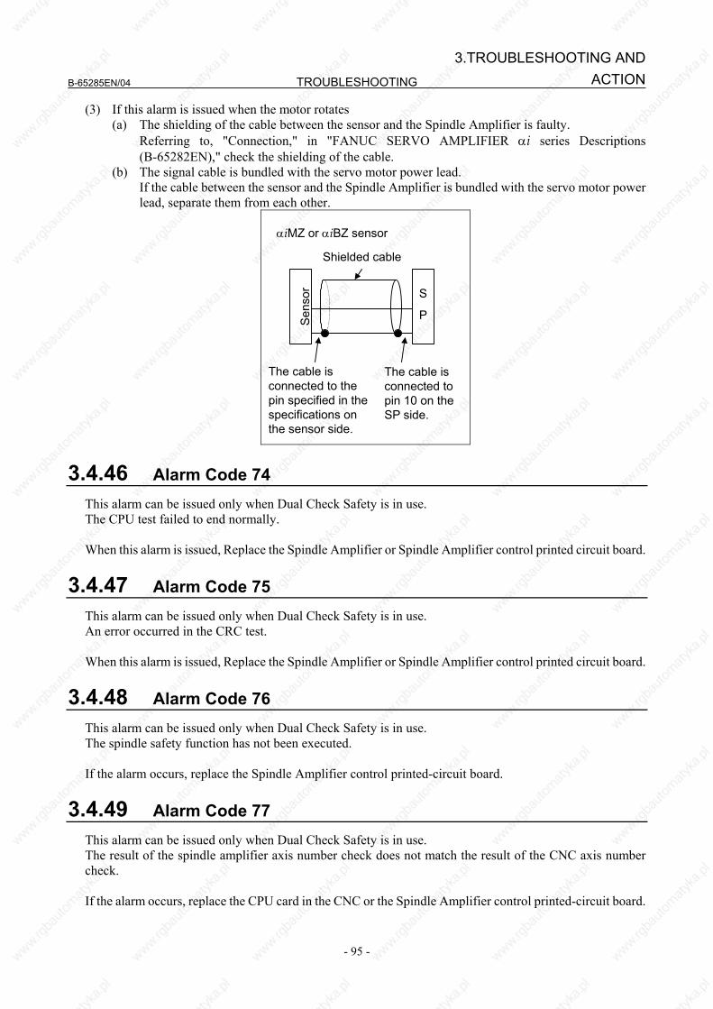
B-65285EN/04 TROUBLESHOOTING
- 95 -
3.TROUBLESHOOTING ANDACTION
(3) If this alarm is issued when the motor rotates (a) The shielding of the cable between the sensor and the Spindle Amplifier is faulty. Referring to, "Connection," in "FANUC SERVO AMPLIFIER αi series Descriptions
(B-65282EN)," check the shielding of the cable. (b) The signal cable is bundled with the servo motor power lead. If the cable between the sensor and the Spindle Amplifier is bundled with the servo motor power
lead, separate them from each other.
S
PSen
sor
The cable is connected to the pin specified in the specifications on the sensor side.
The cable is connected to pin 10 on the SP side.
Shielded cable
αiMZ or αiBZ sensor
3.4.46 Alarm Code 74 This alarm can be issued only when Dual Check Safety is in use. The CPU test failed to end normally. When this alarm is issued, Replace the Spindle Amplifier or Spindle Amplifier control printed circuit board.
3.4.47 Alarm Code 75 This alarm can be issued only when Dual Check Safety is in use. An error occurred in the CRC test. When this alarm is issued, Replace the Spindle Amplifier or Spindle Amplifier control printed circuit board.
3.4.48 Alarm Code 76 This alarm can be issued only when Dual Check Safety is in use. The spindle safety function has not been executed. If the alarm occurs, replace the Spindle Amplifier control printed-circuit board.
3.4.49 Alarm Code 77 This alarm can be issued only when Dual Check Safety is in use. The result of the spindle amplifier axis number check does not match the result of the CNC axis number check. If the alarm occurs, replace the CPU card in the CNC or the Spindle Amplifier control printed-circuit board.
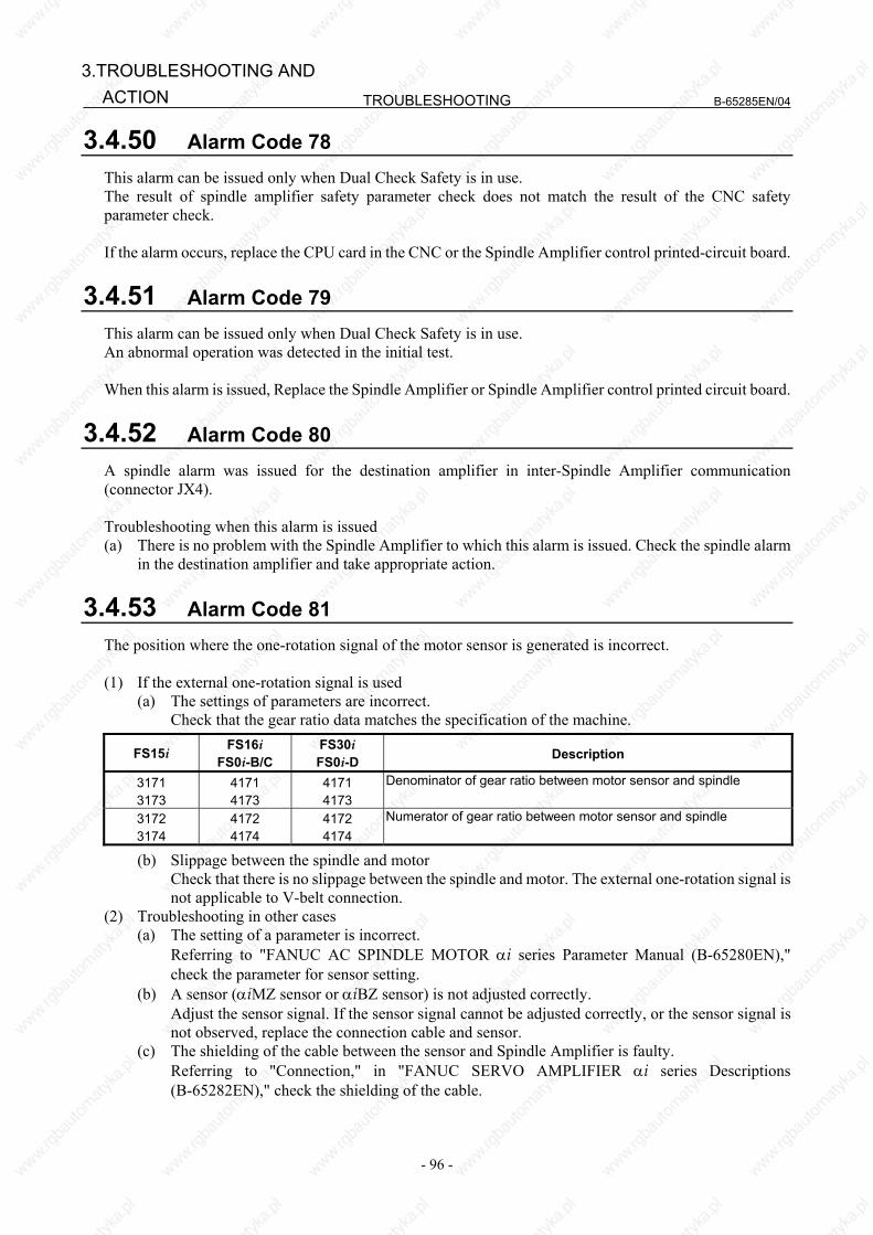
TROUBLESHOOTING B-65285EN/04
- 96 -
3.TROUBLESHOOTING AND ACTION
3.4.50 Alarm Code 78 This alarm can be issued only when Dual Check Safety is in use. The result of spindle amplifier safety parameter check does not match the result of the CNC safety parameter check. If the alarm occurs, replace the CPU card in the CNC or the Spindle Amplifier control printed-circuit board.
3.4.51 Alarm Code 79 This alarm can be issued only when Dual Check Safety is in use. An abnormal operation was detected in the initial test. When this alarm is issued, Replace the Spindle Amplifier or Spindle Amplifier control printed circuit board.
3.4.52 Alarm Code 80 A spindle alarm was issued for the destination amplifier in inter-Spindle Amplifier communication (connector JX4). Troubleshooting when this alarm is issued (a) There is no problem with the Spindle Amplifier to which this alarm is issued. Check the spindle alarm
in the destination amplifier and take appropriate action.
3.4.53 Alarm Code 81 The position where the one-rotation signal of the motor sensor is generated is incorrect. (1) If the external one-rotation signal is used
(a) The settings of parameters are incorrect. Check that the gear ratio data matches the specification of the machine.
FS15i FS16i FS0i-B/C
FS30i FS0i-D Description
3171 3173
4171 4173
4171 4173
Denominator of gear ratio between motor sensor and spindle
3172 3174
4172 4174
4172 4174
Numerator of gear ratio between motor sensor and spindle
(b) Slippage between the spindle and motor Check that there is no slippage between the spindle and motor. The external one-rotation signal is
not applicable to V-belt connection. (2) Troubleshooting in other cases
(a) The setting of a parameter is incorrect. Referring to "FANUC AC SPINDLE MOTOR αi series Parameter Manual (B-65280EN),"
check the parameter for sensor setting. (b) A sensor (αiMZ sensor or αiBZ sensor) is not adjusted correctly. Adjust the sensor signal. If the sensor signal cannot be adjusted correctly, or the sensor signal is
not observed, replace the connection cable and sensor. (c) The shielding of the cable between the sensor and Spindle Amplifier is faulty. Referring to "Connection," in "FANUC SERVO AMPLIFIER αi series Descriptions
(B-65282EN)," check the shielding of the cable.

B-65285EN/04 TROUBLESHOOTING
- 97 -
3.TROUBLESHOOTING ANDACTION
(d) The signal cable is bundled with the servo motor power lead. If the cable between the sensor and Spindle Amplifier is bundled with the servo motor power lead,
separate them from each other. (e) The Spindle Amplifier is faulty. Replace the Spindle Amplifier or Spindle Amplifier control printed circuit board.
S
PSens
or
The cable is connected to the pin specified in the specifications on the sensor side.
The cable is connected to pin 10 on the SP side.
Shielded cable αiMZ or αiBZ sensor
3.4.54 Alarm Code 82 The one-rotation signal of the motor sensor is not generated. Troubleshooting when this alarm is issued (a) The setting of a parameter is incorrect. Referring to "FANUC AC SPINDLE MOTOR αi series Parameter Manual (B-65280EN)," check the
parameter for sensor setting. (b) The αiMZ sensor or αiBZ sensor is not adjusted correctly. Adjust the sensor. If the sensor cannot be adjusted or the signal is not observed, replace the connection
cable and sensor. (c) The external one-rotation signal is faulty. Check the check pin EXTSC1 on the spindle check board. If the signal is not generated per rotation,
replace the connection cable and position coder. (d) The Spindle Amplifier is faulty. Replace the Spindle Amplifier or Spindle Amplifier control printed circuit board.
3.4.55 Alarm Code 83 The Spindle Amplifier checks the pulse counts of phases A and B each time a one-rotation signal is generated. The alarm is issued when a pulse count beyond the specified range is detected. (1) If this alarm is issued when the cable is moved (as in the case where the spindle moves) The conductor may be broken. Replace the cable. If coolant has penetrated into the connector, clean
the connector. (2) Troubleshooting in other cases
(a) The setting of a parameter is incorrect. Referring to "FANUC AC SPINDLE MOTOR αi series Parameter Manual (B-65280EN),"
check the parameter for sensor setting. (b) The αiMZ sensor or αiBZ sensor is not adjusted correctly. Adjust the sensor. If the sensor cannot be adjusted or the signal is not observed, replace the
connection cable and sensor. (c) The shielding of the cable between the sensor and Spindle Amplifier is faulty. Referring to "Connection," in "FANUC SERVO AMPLIFIER αi series Descriptions
(B-65282EN)," check the shielding of the cable.
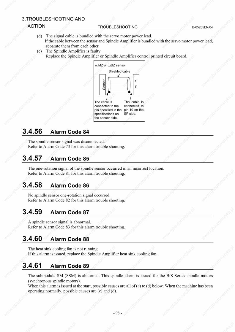
TROUBLESHOOTING B-65285EN/04
- 98 -
3.TROUBLESHOOTING AND ACTION
(d) The signal cable is bundled with the servo motor power lead. If the cable between the sensor and Spindle Amplifier is bundled with the servo motor power lead,
separate them from each other. (e) The Spindle Amplifier is faulty. Replace the Spindle Amplifier or Spindle Amplifier control printed circuit board.
S
PSens
or
The cable is connected to the pin specified in the specifications on the sensor side.
The cable is connected to pin 10 on the SP side.
Shielded cable αiMZ or αiBZ sensor
3.4.56 Alarm Code 84 The spindle sensor signal was disconnected. Refer to Alarm Code 73 for this alarm trouble shooting.
3.4.57 Alarm Code 85 The one-rotation signal of the spindle sensor occurred in an incorrect location. Refer to Alarm Code 81 for this alarm trouble shooting.
3.4.58 Alarm Code 86 No spindle sensor one-rotation signal occurred. Refer to Alarm Code 82 for this alarm trouble shooting.
3.4.59 Alarm Code 87 A spindle sensor signal is abnormal. Refer to Alarm Code 83 for this alarm trouble shooting.
3.4.60 Alarm Code 88 The heat sink cooling fan is not running. If this alarm is issued, replace the Spindle Amplifier heat sink cooling fan.
3.4.61 Alarm Code 89 The submodule SM (SSM) is abnormal. This spindle alarm is issued for the BiS Series spindle motors (synchronous spindle motors). When this alarm is issued at the start, possible causes are all of (a) to (d) below. When the machine has been operating normally, possible causes are (c) and (d).
B-65285EN/04 TROUBLESHOOTING
- 99 -
3.TROUBLESHOOTING ANDACTION
Troubleshooting when this alarm is issued (a) The Spindle Amplifier does not support the SSM. Replace the Spindle Amplifier. (b) The SSM is not mounted or connected. Check the connection of the interface signal cable between JYA4 (Spindle Amplifier) and CX31
(SSM). (c) The interface signal between the Spindle Amplifier and SSM is disconnected. Check the connection of the interface signal cable between JYA4 (Spindle Amplifier) and CX31
(SSM). (d) The SSM is faulty. Replace the SSM.
3.4.62 Alarm Code 90 An unexpected rotation state (state in which the polarity in the torque command differs that of acceleration) was detected. This spindle alarm is issued for the BiS Series spindle motors (synchronous spindle motors). When this alarm is issued at the start, possible causes are all of (a) to (d) below. When the machine has been operating normally, it is highly possible that the cause is (c) or (d). Troubleshooting when this alarm is issued (a) There is a setting error in a parameter (number of teeth of the motor sensor or number of phases of the
motor). Refer to the FANUC AC SPINDLE MOTOR αi series Parameter Manual (B-65280EN) to check the
relevant parameters. (b) There is a setting error in an AMR offset-related parameter (No. 4084 or 4085). Parameter No. 4084 (AMR offset) is adjusted for each machine. Readjust this parameter when the
phase relationship between the magnetic pole 0-deg position of the rotor and the one-rotation signal position of the sensor changes due to the replacement of the sensor or slippage of the shaft or when the parameter is loaded from another machine.
Parameter No. 4085 is provided for AMR offset adjustment. Normally, this parameter must be set to "0".
(c) When this alarm is issued after the spindle is banged, a possible cause is a change to the phase relationship between the motor sensor and rotor due to slippage of the motor sensor or rotor shaft.
(d) A count error occurs in the motor sensor due to noise. Apply appropriate countermeasures against noise.
3.4.63 Alarm Code 91 A count error occurred for the magnetic pole position (a large difference between the magnetic pole position at the one-rotation signal position and the setting of parameter No. 4084 (AMR offset) was detected). This spindle alarm is issued for the BiS Series spindle motors (synchronous spindle motors). When this alarm is issued at the start, possible causes are both (a) and (b) below. When the machine has been operating normally, check (b) and take appropriate action. Troubleshooting when this alarm is issued (a) There is a setting error in a parameter (number of teeth of the motor sensor or number of phases of the
motor). Refer to the FANUC AC SPINDLE MOTOR αi series Parameter Manual (B-65280EN) to check the
relevant parameters. (b) An unnecessary one-rotation signal is generated or a count error occurs for feedback pulses due to
slippage of the sensor ring or noise. Check whether the motor sensor slips. When there is no problem with the motor sensor, take
appropriate countermeasures against noise.
TROUBLESHOOTING B-65285EN/04
- 100 -
3.TROUBLESHOOTING AND ACTION
3.4.64 Alarm Code 92 The actual motor speed exceeded the overspeed level corresponding to the velocity command. When this alarm is issued at the start, possible causes are all of (a) to (c) below. When the machine has been operating normally, it is highly possible that the cause is noise in (c). Troubleshooting when this alarm is issued (a) There is a setting error in a parameter (number of teeth of the motor sensor or number of phases of the
motor). Refer to the FANUC AC SPINDLE MOTOR αi series Parameter Manual (B-65280EN) to check the
relevant parameters. (b) When a BiS Series spindle motor (synchronous spindle motor) is driven, there is a setting error in an
AMR offset-related parameter (No. 4084 or 4085). Parameter No. 4084 (AMR offset) is adjusted for each machine. Readjust this parameter when the
phase relationship between the magnetic pole 0-deg position of the rotor and the one-rotation signal position of the sensor changes due to the replacement of the sensor or slippage of the shaft or when the parameter is loaded from another machine.
Parameter No. 4085 is provided for AMR offset adjustment. Normally, this parameter must be set to "0".
(d) A count error occurs in the motor sensor due to noise. Apply appropriate countermeasures against noise.
3.4.65 Alarm Codes A, A1, and A2 The control program is not running. An error was detected when the control program was running. (1) If this alarm is issued when the spindle amplifier power is switched on
(a) Wrong software specification (b) Defective printed-circuit board Replace the Spindle Amplifier or Spindle Amplifier control printed-circuit board.
(2) If this alarm is issued when the motor is active. (a) Influence by noise Referring to "Installation" in "FANUC SERVO AMPLIFIER αi series Descriptions
(B-65282EN)," check the grounding wire. If the spindle sensor signal wire is bundled together with any motor power wire, separate them.
3.4.66 Alarm Code b0 An error occurred in communication between amplifiers (Spindle Amplifier, Servo Amplifier, and Power Supply). Troubleshooting when this alarm is issued (1) If this alarm is issued immediately after the power supply of CNC is turned on
(a) Check the way the connectors are coupled. Normally, CXA2A and CXA2B must be coupled. (b) The cable is defective. Check the connection pin number. If there is any problem, correct it. Alternatively, replace the cable. (c) The Spindle Amplifier, Servo Amplifier, or Power Supply is defective. Replace the Spindle Amplifier, Servo Amplifier, or Power Supply. Alternatively, replace the
Spindle Amplifier, Servo Amplifier, or Power Supply control printed-circuit board.

B-65285EN/04 TROUBLESHOOTING
- 101 -
3.TROUBLESHOOTING ANDACTION
3.4.67 Alarm Codes C0,C1, and C2 An error occurred in serial communication data between the CNC and Spindle Amplifier. Troubleshooting when this alarm is issued (a) The Spindle Amplifier is defective. Replace the Spindle Amplifier or Spindle Amplifier control printed-circuit board. (b) The CNC is defective. Replace the board or module related to the serial spindle.
3.4.68 Alarm Code C3 In spindle switching, a mismatch is found between the switching request signal (SPSL) and the internal status of the motor/spindle sensor signal switching circuit (submodule SW). Troubleshooting when this alarm is issued The submodule SW (SSW) is defective. Replace the submodule SW (SSW).
3.4.69 Alarm Code C4 An invalid learning cycle is set in learning control in the time synchronization mode. Troubleshooting when this alarm is issued (a) Check whether the value specified in the velocity command is appropriate. (b) Check whether the setting of the learning cycle (parameter No. 4425) is within a range between 20 and
4800.
3.4.70 Alarm Code C5 An invalid value is set for the highest or lowest degree of a dynamic characteristic compensation element in learning control. Troubleshooting when this alarm is issued Decrease the setting of the highest (parameter No. 4427) or lowest (parameter No. 4428) of dynamic
characteristic compensation element Gx.
3.4.71 Alarm Code C7 An invalid reference angle cycle is set in learning control in the angle synchronization mode. Troubleshooting when this alarm is issued Increase the setting of parameter No. 4425 (number of divisions per cycle) in learning control.
3.4.72 Alarm Code C8 In spindle synchronization, the speed deviation (difference between the specified speed at the spindle end calculated based on the position error and position gain and the actual speed) exceeded the alarm detection level (parameter No. 4515).

TROUBLESHOOTING B-65285EN/04
- 102 -
3.TROUBLESHOOTING AND ACTION
(1) When this alarm is issued immediately after the motor excitation (SFR, SRV) is turned off, then on again in spindle synchronization
This alarm may be issued because the spindle motor is accelerated to eliminate the accumulated position error while the motor excitation is off. Modify the sequence so that the motor excitation is turned off after spindle synchronization is released.
(2) When this alarm is issued during cutting (a) A possible cause is overload. Review the cutting conditions. (b) When no overload occurs, review whether the alarm detection level setting is appropriate.
3.4.73 Alarm Code C9 In spindle synchronization, the position error exceeded the alarm detection level (parameter No. 4516). For troubleshooting when this alarm is issued, see the subsection about alarm code C8.
3.4.74 Alarm Code d0 In tandem control, the speed polarity relationship between the master motor and slave motor is abnormal. Troubleshooting when this alarm is issued Check the setting related to the rotation direction (FS16: bit 2 of parameter No. 4353).
3.4.75 Alarm Code d1 An error occurred during spindle adjustment function operation. Troubleshooting when this alarm is issued Refer to the description of the error and action to be taken that are displayed on the SERVO GUIDE.
3.4.76 Alarm Code d2 Communication between the sensor (serial) and Spindle Amplifier is disconnected. When this alarm is issued at the start, possible causes are all of (a) to (d) below. When the machine has been operating normally, possible causes are (c) and (d). Troubleshooting when this alarm is issued (a) There is a parameter setting error. Refer to the section, "START-UP," in the FANUC AC SPINDLE MOTOR αi series Parameter
Manual (B-65280EN) to check the settings of the sensor setting parameters. (b) The Spindle Amplifier is not supported. Check the items related to the section, "PARAMETERS RELATED TO DETECTORS," in the
FANUC SERVO AMPLIFIER αi series Descriptions (B-65282EN). (c) The cable is broken or connected incorrectly. Replace the cable or check the connection. (d) The Spindle Amplifier is defective. Replace the Spindle Amplifier or Spindle Amplifier control printed-circuit board.
B-65285EN/04 TROUBLESHOOTING
- 103 -
3.TROUBLESHOOTING ANDACTION
3.4.77 Alarm Code d3 Serial data between the sensor (serial) and Spindle Amplifier that was received by the Spindle Amplifier was detected being destroyed by noise. Troubleshooting when this alarm is issued (a) Check the shielding of the cable between the sensor (serial) and Spindle Amplifier. Check the items related to the section, "Detectors," in the FANUC SERVO AMPLIFIER αi series
Descriptions (B-65282EN).
3.4.78 Alarm Code d4 A change to position data from the sensor (serial) was detected exceeding the expected range. When this alarm is issued at the start, possible causes are both (a) and (b) below. When the machine has been operating normally, the possible cause is (b). Troubleshooting when this alarm is issued (a) There is a parameter setting error. Refer to the section, "Parameters Related to Start-up," in the FANUC AC SPINDLE MOTOR αi
series Parameter Manual (B-65280EN) to check the settings of the sensor setting parameters. (b) Check the shielding of the cable between the sensor (serial) and Spindle Amplifier. Check the items related to the section, "Detectors," in the FANUC SERVO AMPLIFIER αi series
Descriptions (B-65282EN).
3.4.79 Alarm Code d7 A communication error occurred in an electronic device on the Spindle Amplifier control circuit. Troubleshooting when this alarm is issued The Spindle Amplifier control printed-circuit board becomes loose or the Spindle Amplifier is
abnormal. Check whether the Spindle Amplifier control printed-circuit board is mounted correctly. When the board is mounted correctly, replace the Spindle Amplifier.
3.4.80 Alarm Code d9 An error occurred in the inner circuit of the sensor (serial). Troubleshooting when this alarm is issued (a) The detection circuit is abnormal. Replace the detection circuit.
3.4.81 Alarm Code E0 The number of pulses between one-rotation signals of the sensor (serial) is outside the specified range. Troubleshooting when this alarm is issued (a) The detection circuit is abnormal. Replace the detection circuit.
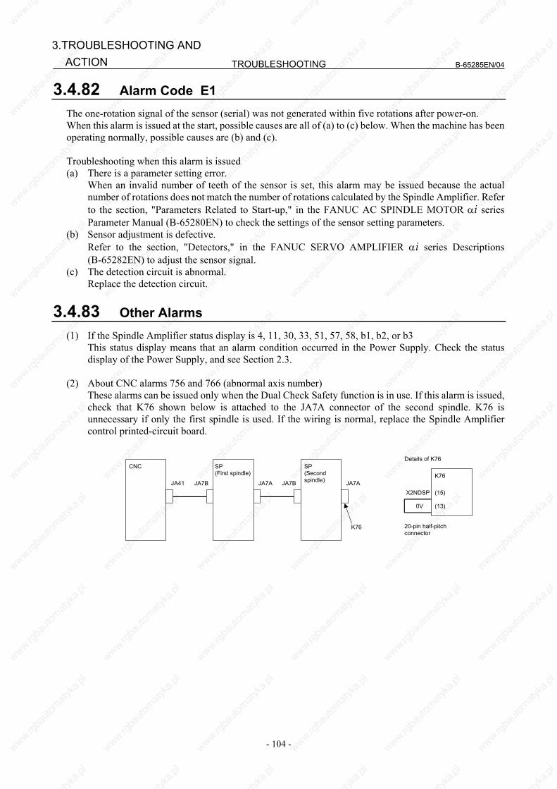
TROUBLESHOOTING B-65285EN/04
- 104 -
3.TROUBLESHOOTING AND ACTION
3.4.82 Alarm Code E1 The one-rotation signal of the sensor (serial) was not generated within five rotations after power-on. When this alarm is issued at the start, possible causes are all of (a) to (c) below. When the machine has been operating normally, possible causes are (b) and (c). Troubleshooting when this alarm is issued (a) There is a parameter setting error. When an invalid number of teeth of the sensor is set, this alarm may be issued because the actual
number of rotations does not match the number of rotations calculated by the Spindle Amplifier. Refer to the section, "Parameters Related to Start-up," in the FANUC AC SPINDLE MOTOR αi series Parameter Manual (B-65280EN) to check the settings of the sensor setting parameters.
(b) Sensor adjustment is defective. Refer to the section, "Detectors," in the FANUC SERVO AMPLIFIER αi series Descriptions
(B-65282EN) to adjust the sensor signal. (c) The detection circuit is abnormal. Replace the detection circuit.
3.4.83 Other Alarms (1) If the Spindle Amplifier status display is 4, 11, 30, 33, 51, 57, 58, b1, b2, or b3 This status display means that an alarm condition occurred in the Power Supply. Check the status
display of the Power Supply, and see Section 2.3. (2) About CNC alarms 756 and 766 (abnormal axis number) These alarms can be issued only when the Dual Check Safety function is in use. If this alarm is issued,
check that K76 shown below is attached to the JA7A connector of the second spindle. K76 is unnecessary if only the first spindle is used. If the wiring is normal, replace the Spindle Amplifier control printed-circuit board.
SP (First spindle)
CNC
JA41 JA7B JA7A
SP (Second spindle)JA7B
K76
JA7A
X2NDSP
0V
(15)
(13)
K76
20-pin half-pitchconnector
Details of K76
B-65285EN/04 TROUBLESHOOTING
- 105 -
3.TROUBLESHOOTING ANDACTION
3.5 αCi SERIES SPINDLE AMPLIFIER MODULE
This section explains those alarm codes for the αCi series which require troubleshooting sequences that are different from those for the αi series even when the alarm numbers are the same. For explanations about the alarm codes not stated herein, see the descriptions about the corresponding number given in Section 2.4, "Spindle Amplifier."
3.5.1 Alarm Code 12 An excessive motor current was detected. An excessively large current flowed into the DC link of the main circuit. For SPMC-2.2i to -15i An overload, overcurrent, or a low control power supply voltage was detected in the power module (IPM) of the main circuit. (1) If this alarm is issued on SPMC-2.2i to -15i Check alarm code 09 as well. (2) If this alarm is issued immediately after a spindle rotation command is specified
(a) The motor power lead is faulty. Check for a short circuit between motor power leads and short-circuit to ground, and replace the
power lead as required. (b) The insulation of the motor winding is defective. If the motor is short-circuited to ground, replace the motor. (c) The parameters specific to the motor are not set correctly. Refer to "FANUC AC SPINDLE MOTOR αi series Parameter Manual (B-65280EN)." (d) The SPMC is faulty. A power element (IGBT, IPM) may be destroyed. Replace the SPMC.
(3) If this alarm is issued during spindle rotation (a) Belt slippage It is likely that there may be belt slippage between the spindle and motor. Clean the pulleys and
adjust the belt tension. (b) The parameters specific to the motor are not set correctly. Referring to "FANUC AC SPINDLE MOTOR αi series Parameter Manual (B-65280EN)," check
the parameters specific to the motor. (c) The SPMC is faulty. A power element (IGBT, IPM) may be destroyed. Replace the SPMC. If the amplifier setting condition is not satisfied, or cooling is insufficient because the heat sink is
dirty, the power elements may be destroyed. When the heat sink on the back of the amplifier is too dirty, clean the heat sink, for example, by
blowing air. Consider the use of a structure that prevents the heat sink from being directly exposed to coolant.
For the installation condition, refer to "FANUC SERVO AMPLIFIER αi series Descriptions (B-65282EN)."

TROUBLESHOOTING B-65285EN/04
- 106 -
3.TROUBLESHOOTING AND ACTION
3.5.2 Alarm Code 35 There is a large difference between the motor speed calculated from the position coder and the motor speed estimated with the spindle software. (1) If an alarm is issued when a rotation command is entered
(a) Error in the position coder setting parameter Correctly specify the bits representing the relationships between the direction of position coder
rotation and that of spindle rotation and between the direction of spindle rotation and that of motor rotation.
FS15i FS16i Description 3000#0 4000#0 Spindle and spindle motor rotation directions 3001#4 4001#4 Spindle sensor (position coder) mounting direction
(b) Invalid gear ratio parameter setting Check to see if an incorrect gear ratio has been specified. This value is used to convert the position coder speed to the motor speed. Be sure to specify the
correct value. FS15i FS16i Description
3056 to 3059 4056 to 4059 Spindle-motor gear ratio data (c) Clutch/gear signal error Make sure that the entered clutch/gear signals (CTH1A, CTH2A) are correct with respect to the
actually selected gear. FS15i FS16i #7 #6 #5 #4 #3 #2 #1 #0
First spindle G227 G070 CTH1A CTH2A
Second spindle G235 G074 CTH1B CTH2B
(d) Belt slippage between the spindle and spindle motor Make adjustments so that no belt slippage will occur between the spindle and spindle motor.
(2) If an alarm is issued during a cutting operation An overload has occurred to decrease the motor speed. Review the cutting condition.

B-65285EN/04 TROUBLESHOOTING
- 107 -
4.REPLACING AMPLIFIERCOMPONENTS
4 REPLACING AMPLIFIER COMPONENTS This chapter describes how to replace a fan motor, absolute Pulsecoder battery, fuses, and printed-circuit board.
WARNING Because the Servo Amplifier uses a large-capacitance electrolytic capacitor
internally, the Servo Amplifier remains charged for a while even after the power is turned off. Before touching the Servo Amplifier for maintenance or other purposes, ensure your safety by measuring the residual voltage in the DC link with a tester and confirming that the charge indication LED (red) is off.
4.1 REPLACEMENT OF A FAN MOTOR (1) Fan motor for internal cooling Replace the internal fan motor, according to the procedure shown in the figure below. When replacing the fan motor, be careful about the direction of the fan motor (air blow direction), the
direction of the connector, etc.
Air blow direction
Fan unit
(1) Hold the two tabs and get the fan unitoff the latch.
Tab Fan unit (60-mm-wide)
White Black Red
Be careful about the connector key direction.
(2) Remove the fan unit by pulling it upward.
Tab
Fan unit (90-mm-wide)
Fan unit (150-mm-wide)
Be careful about the connector key direction.
Red
Black
White
* Be careful about the fan motor and connector directions.

TROUBLESHOOTING B-65285EN/04
- 108 -
4.REPLACING AMPLIFIER COMPONENTS
(2) Fan motor for cooling the external radiator <1> Remove the two sheet metal mounting screws (for the 60-mm-wide model only), and detach the
fan motor from the unit together with the sheet metal. <2> Remove the fan motor mounting screws (two for one fan motor and four for two fan motors). <3> Remove the connector mounting screws (two and four for the 300-mm-wide model).
When replacing the fan motor, be careful about the direction of the fan motor (air blow direction), the direction of the connector, etc.
Air blow direction
60 mm wide/90 mm wide
Sheet metal mounting screws
Connector mounting screw Fan motor mounting screw
Air blow direction
150 mm wide
Connector mounting screw Fan motor mounting screw
Air blow direction
300 mm wide
Connector mounting screw Fan motor mounting screw
Specification number of fan unit - Power Supply
Internal cooling fan Radiator cooling fan Model name Fan unit (*1) Fan motor Fan unit (*1) Fan motor
αiPS 5.5 - A90L-0001-0441/39 - - αiPS 11 αiPS 15
αiPS 11HV αiPS 18HV
- A90L-0001-0441/39 A06B-6110-C603 A90L-0001-0508
αiPS 26 αiPS 30 αiPS 37
- A90L-0001-0441/39 (A06B-6110-C604) A90L-0001-0509
αiPS 30HV αiPS 45HV αiPS 60HV
A06B-6110-C607
A90L-0001-0441/39 A90L-0001-0511(*2)
(A06B-6110-C604) A90L-0001-0509
αiPS 55 αiPS 75HV
αiPS 100HV
A06B-6110-C607 Two are used.
A90L-0001-0441/39 A90L-0001-0511(*2)
(A06B-6110-C604) Two are used.
A90L-0001-0509 Two are used.

B-65285EN/04 TROUBLESHOOTING
- 109 -
4.REPLACING AMPLIFIERCOMPONENTS
- Servo Amplifier (1) 200 V input with one axis
Internal cooling fan Radiator cooling fan Model name Fan unit (*1) Fan motor Fan unit (*1) Fan motor
αiSV 4 A06B-6110-C605 A90L-0001-0510 αiSV 20 A06B-6110-C605 A90L-0001-0510 - - αiSV 40 A06B-6110-C605 A90L-0001-0510 - - αiSV 80 A06B-6110-C605 A90L-0001-0510 - -
αiSV 160 A06B-6110-C605 A90L-0001-0510 A06B-6110-C602 A90L-0001-0507/B αiSV 360 A06B-6110-C607 A90L-0001-0511 (A06B-6110-C604) A90L-0001-0509 αiSV 20L A06B-6110-C605 A90L-0001-0510 αiSV 40L A06B-6110-C605 A90L-0001-0510 αiSV 80L A06B-6110-C605 A90L-0001-0510 A06B-6110-C602 A90L-0001-0507/B
αiSV 160L A06B-6110-C606 A90L-0001-0510 A06B-6110-C603 A90L-0001-0508 (2) 200 V input with two axes
Internal cooling fan Radiator cooling fan Model name Fan unit (*1) Fan motor Fan unit (*1) Fan motor
αiSV 4/4 A06B-6110-C605 A90L-0001-0510 - - αiSV 4/20 A06B-6110-C605 A90L-0001-0510
αiSV 20/20 A06B-6110-C605 A90L-0001-0510 - - αiSV 20/40 A06B-6110-C605 A90L-0001-0510 - - αiSV 40/40 A06B-6110-C605 A90L-0001-0510 A06B-6110-C601 A90L-0001-0507/A αiSV 40/80 A06B-6110-C605 A90L-0001-0510 A06B-6110-C601 A90L-0001-0507/A αiSV 80/80 A06B-6110-C605 A90L-0001-0510 A06B-6110-C601 A90L-0001-0507/A
αiSV 80/160 A06B-6110-C606 A90L-0001-0510 A06B-6110-C603 A90L-0001-0508 αiSV 160/160 A06B-6110-C606 A90L-0001-0510 A06B-6110-C603 A90L-0001-0508 αiSV 20/20L A06B-6110-C605 A90L-0001-0510 αiSV 20/40L A06B-6110-C605 A90L-0001-0510 A06B-6110-C601 A90L-0001-0507/A αiSV 40/40L A06B-6110-C605 A90L-0001-0510 A06B-6110-C601 A90L-0001-0507/A αiSV 40/80L A06B-6110-C606 A90L-0001-0510 A06B-6110-C603 A90L-0001-0508 αiSV 80/80L A06B-6110-C606 A90L-0001-0510 A06B-6110-C603 A90L-0001-0508
(*1) A fan unit is a set of a fan motor and a cover for mounting it. A fan motor can be replaced separately from the fan unit. The fan unit A06B-6110-C604, enclosed in parentheses, cannot be dismounted from the outside. So replace only the fan motor, which can be dismounted from the outside. (See Section III-1.3, "HOW TO REPLACE THE FAN MOTOR.")
(*2) For A06B-6110-C607 (3) 200 V input with three axes
Internal cooling fan Radiator cooling fan Model name Fan unit (*1) Fan motor Fan unit Fan motor
αiSV 4/4/4 A06B-6110-C605 A90L-0001-0510 - - αiSV 20/20/20 A06B-6110-C605 A90L-0001-0510 - A90L-0001-0385/T(*2)αiSV 20/20/40 A06B-6110-C605 A90L-0001-0510 - -
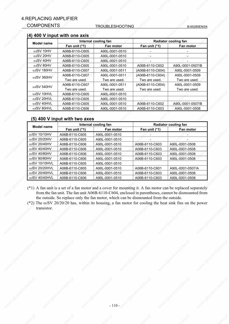
TROUBLESHOOTING B-65285EN/04
- 110 -
4.REPLACING AMPLIFIER COMPONENTS
(4) 400 V input with one axis Internal cooling fan Radiator cooling fan Model name
Fan unit (*1) Fan motor Fan unit (*1) Fan motor αiSV 10HV A06B-6110-C605 A90L-0001-0510 - - αiSV 20HV A06B-6110-C605 A90L-0001-0510 - - αiSV 40HV A06B-6110-C605 A90L-0001-0510 - - αiSV 80HV A06B-6110-C605 A90L-0001-0510 A06B-6110-C602 A90L-0001-0507/B
αiSV 180HV A06B-6110-C607 A90L-0001-0511 (A06B-6110-C604) A90L-0001-0509
αiSV 360HV A06B-6110-C607 Two are used.
A90L-0001-0511 Two are used.
(A06B-6110-C604) Two are used.
A90L-0001-0509 Two are used.
αiSV 540HV A06B-6110-C607 Two are used.
A90L-0001-0511 Two are used.
(A06B-6110-C604) Two are used.
A90L-0001-0509 Two are used.
αiSV 10HVL A06B-6110-C605 A90L-0001-0510 αiSV 20HVL A06B-6110-C605 A90L-0001-0510 αiSV 40HVL A06B-6110-C605 A90L-0001-0510 A06B-6110-C602 A90L-0001-0507/B αiSV 80HVL A06B-6110-C606 A90L-0001-0510 A06B-6110-C603 A90L-0001-0508
(5) 400 V input with two axes
Internal cooling fan Radiator cooling fan Model name Fan unit (*1) Fan motor Fan unit (*1) Fan motor
αiSV 10/10HV A06B-6110-C605 A90L-0001-0510 - - αiSV 20/20HV A06B-6110-C605 A90L-0001-0510 - - αiSV 20/40HV A06B-6110-C606 A90L-0001-0510 A06B-6110-C603 A90L-0001-0508 αiSV 40/40HV A06B-6110-C606 A90L-0001-0510 A06B-6110-C603 A90L-0001-0508 αiSV 40/80HV A06B-6110-C606 A90L-0001-0510 A06B-6110-C603 A90L-0001-0508 αiSV 80/80HV A06B-6110-C606 A90L-0001-0510 A06B-6110-C603 A90L-0001-0508 αiSV 10/10HVL A06B-6110-C605 A90L-0001-0510 αiSV 20/20HVL A06B-6110-C605 A90L-0001-0510 A06B-6110-C601 A90L-0001-0507/A αiSV 20/40HVL A06B-6110-C606 A90L-0001-0510 A06B-6110-C603 A90L-0001-0508 αiSV 40/40HVL A06B-6110-C606 A90L-0001-0510 A06B-6110-C603 A90L-0001-0508
(*1) A fan unit is a set of a fan motor and a cover for mounting it. A fan motor can be replaced separately
from the fan unit. The fan unit A06B-6110-C604, enclosed in parentheses, cannot be dismounted from the outside. So replace only the fan motor, which can be dismounted from the outside.
(*2) The αiSV 20/20/20 has, within its housing, a fan motor for cooling the heat sink fins on the power transistor.
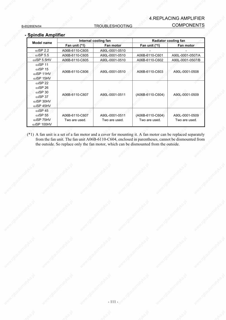
B-65285EN/04 TROUBLESHOOTING
- 111 -
4.REPLACING AMPLIFIERCOMPONENTS
- Spindle Amplifier Internal cooling fan Radiator cooling fan Model name
Fan unit (*1) Fan motor Fan unit (*1) Fan motor αiSP 2.2 A06B-6110-C605 A90L-0001-0510 - - αiSP 5.5 A06B-6110-C605 A90L-0001-0510 A06B-6110-C601 A90L-0001-0507/A
αiSP 5.5HV A06B-6110-C605 A90L-0001-0510 A06B-6110-C602 A90L-0001-0507/B αiSP 11 αiSP 15
αiSP 11HV αiSP 15HV
A06B-6110-C606 A90L-0001-0510 A06B-6110-C603 A90L-0001-0508
αiSP 22 αiSP 26 αiSP 30 αiSP 37
αiSP 30HV αiSP 45HV
A06B-6110-C607 A90L-0001-0511 (A06B-6110-C604) A90L-0001-0509
αiSP 45 αiSP 55
αiSP 75HV αiSP 100HV
A06B-6110-C607 Two are used.
A90L-0001-0511 Two are used.
(A06B-6110-C604) Two are used.
A90L-0001-0509 Two are used.
(*1) A fan unit is a set of a fan motor and a cover for mounting it. A fan motor can be replaced separately
from the fan unit. The fan unit A06B-6110-C604, enclosed in parentheses, cannot be dismounted from the outside. So replace only the fan motor, which can be dismounted from the outside.
TROUBLESHOOTING B-65285EN/04
- 112 -
4.REPLACING AMPLIFIER COMPONENTS
4.2 REPLACING BATTERY FOR ABSOLUTE PULSECODERS
4.2.1 Overview • When the voltage of the batteries for absolute Pulsecoders becomes low, alarm 307 or 306 occurs, with
the following indication in the CNC state display at the bottom of the CNC screen. Alarm 307 (alarm indicating the voltage of the battery becomes low) : The indication "APC" blinks in reversed display. Alarm 306 (battery zero alarm) : The indication "ALM" blinks in reversed display.
• When alarm 307 (alarm indicating the voltage of the battery becomes low) occurs, replace the battery as soon as possible. In general, the battery should be replaced within one or two weeks, however, this depends on the number of Pulsecoders used.
• When alarm 306 (battery zero alarm) occurs, Pulsecoders are reset to the initial state, in which absolute positions are not held. Alarm 300 (reference position return request alarm) also occurs, indicating that reference position return is required.
• In general, replace the batteries periodically within the service life listed below. - A06B-6050-K061 or D-size alkaline dry cells (LR20) : Two years (for each six-axis
configuration) - A06B-6073-K001 : Two years (for each three-axis configuration) - A06B-6114-K504 : One year (for each three-axis configuration)
NOTE
The above values indicate the estimated service life of batteries used with FANUC absolute Pulsecoders. The actual battery service life depends on the machine configuration based on, for example, detector types. For details, contact the machine tool builder.
4.2.2 Replacing Batteries To prevent absolute position information in absolute Pulsecoders from being lost, turn on the machine power before replacing the battery. The replacement procedure is described below. <1> Ensure that the power to the servo amplifier is turned on. <2> Ensure that the machine is in the emergency stop state (the motor is inactive). <3> Ensure that the DC link charge LED of the servo amplifier is off. <4> Detach the old batteries and attach new ones. The replacement of the batteries in a separate battery case and the replacement of the battery built into the servo amplifier are described below in detail.
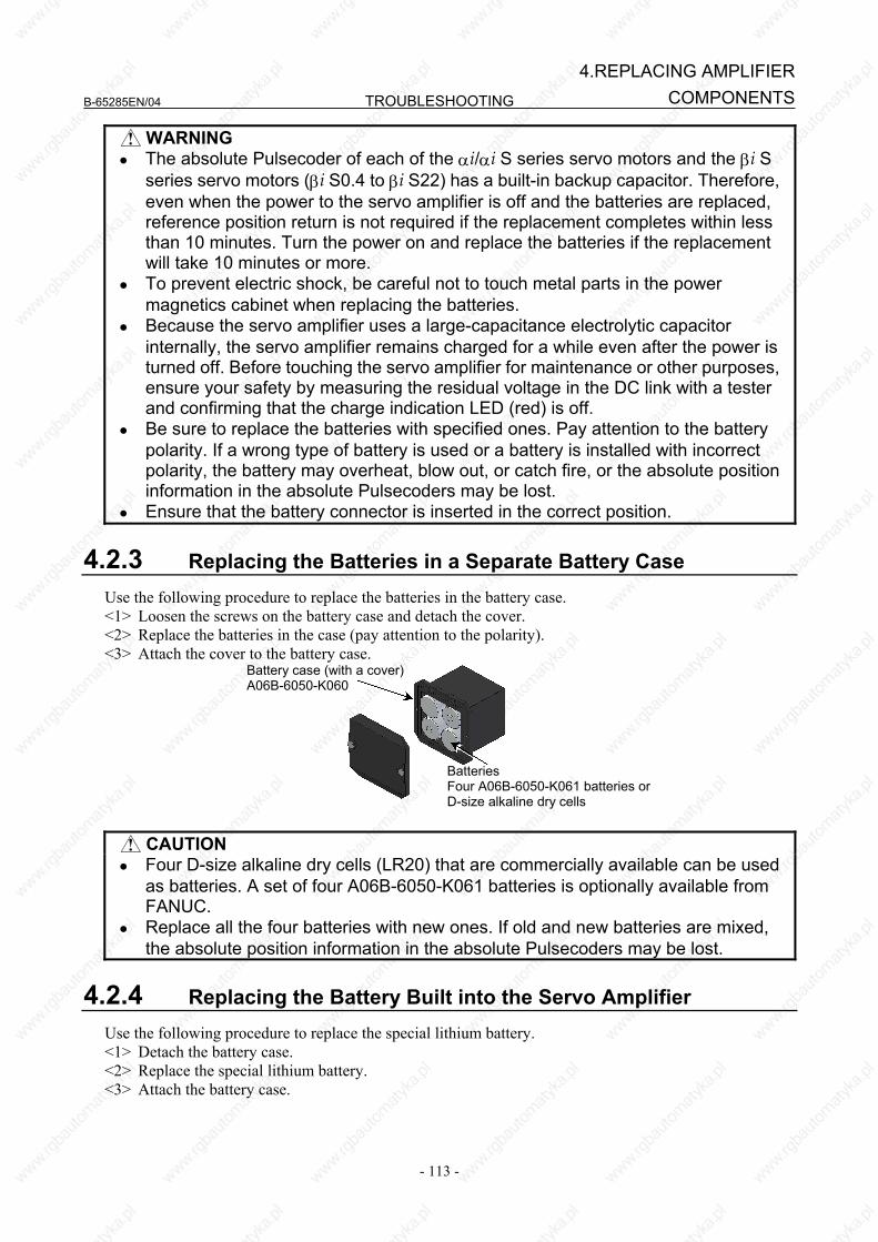
B-65285EN/04 TROUBLESHOOTING
- 113 -
4.REPLACING AMPLIFIERCOMPONENTS
WARNING • The absolute Pulsecoder of each of the αi/αi S series servo motors and the βi S
series servo motors (βi S0.4 to βi S22) has a built-in backup capacitor. Therefore, even when the power to the servo amplifier is off and the batteries are replaced, reference position return is not required if the replacement completes within less than 10 minutes. Turn the power on and replace the batteries if the replacement will take 10 minutes or more.
• To prevent electric shock, be careful not to touch metal parts in the power magnetics cabinet when replacing the batteries.
• Because the servo amplifier uses a large-capacitance electrolytic capacitor internally, the servo amplifier remains charged for a while even after the power is turned off. Before touching the servo amplifier for maintenance or other purposes, ensure your safety by measuring the residual voltage in the DC link with a tester and confirming that the charge indication LED (red) is off.
• Be sure to replace the batteries with specified ones. Pay attention to the battery polarity. If a wrong type of battery is used or a battery is installed with incorrect polarity, the battery may overheat, blow out, or catch fire, or the absolute position information in the absolute Pulsecoders may be lost.
• Ensure that the battery connector is inserted in the correct position.
4.2.3 Replacing the Batteries in a Separate Battery Case Use the following procedure to replace the batteries in the battery case. <1> Loosen the screws on the battery case and detach the cover. <2> Replace the batteries in the case (pay attention to the polarity). <3> Attach the cover to the battery case.
Battery case (with a cover)A06B-6050-K060
Batteries Four A06B-6050-K061 batteries or D-size alkaline dry cells
CAUTION
• Four D-size alkaline dry cells (LR20) that are commercially available can be used as batteries. A set of four A06B-6050-K061 batteries is optionally available from FANUC.
• Replace all the four batteries with new ones. If old and new batteries are mixed, the absolute position information in the absolute Pulsecoders may be lost.
4.2.4 Replacing the Battery Built into the Servo Amplifier Use the following procedure to replace the special lithium battery. <1> Detach the battery case. <2> Replace the special lithium battery. <3> Attach the battery case.

TROUBLESHOOTING B-65285EN/04
- 114 -
4.REPLACING AMPLIFIER COMPONENTS
CAUTION • Purchase the battery from FANUC because it is not commercially available. It is
therefore recommended that you have a backup battery. • When the built-in battery is used, do not connect BATL (B3) of connector
CXA2A/CXA2B. Also, do not connect two or more batteries to the same BATL (B3) line. These connections are dangerous because battery output voltages may be short-circuited, causing the batteries to overheat.
• Install the battery in the servo amplifier in a direction that allows slack in the cable. If the battery cable is under tension, a bad connection may occur.
• If the +6 V pin and 0 V pin are short-circuited, the battery may overheat, blow out, or catch fire, or the absolute position information in the absolute Pulsecoders may be lost.
• When inserting the connector, align it to the connector pins.
Battery Battery case
Insertion direction
Red: +6 V
Black: 0 VConnector
CX5X
+6 V 0 V
[Battery sets and outlines]
Battery ordering drawing number
Manufacturer model number Applicable servo amplifier
Battery case ordering drawing
number Outline
αi series 60/90 mm width A06B-6114-K505 A06B-6114-K504
(Note) BR-2/3AGCT4A
(Panasonic) αi series 150/300 mm width A06B-6114-K506
NOTE When using an old-type battery BR-CCF2TH, order a battery case applicable for
battery A06B-6114-K504.
Used batteries Old batteries should be disposed as "INDUSTRIAL WASTES" according to the regulations of the country or autonomy where your machine has been installed.
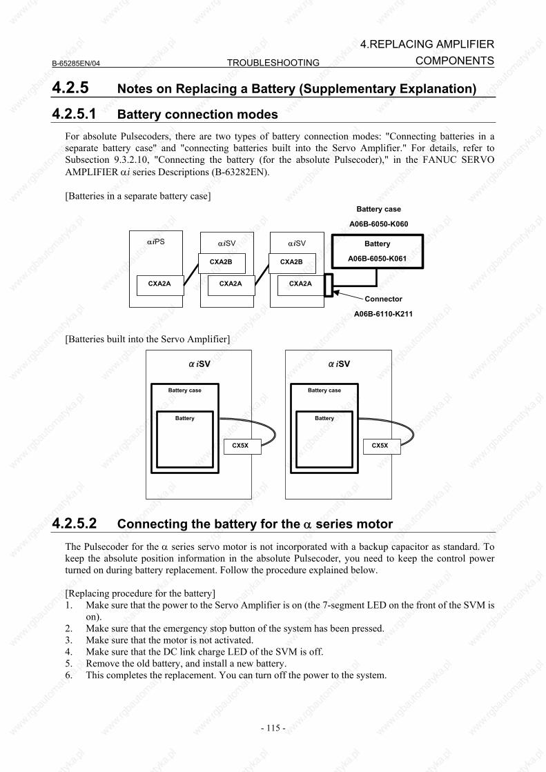
B-65285EN/04 TROUBLESHOOTING
- 115 -
4.REPLACING AMPLIFIERCOMPONENTS
4.2.5 Notes on Replacing a Battery (Supplementary Explanation)
4.2.5.1 Battery connection modes For absolute Pulsecoders, there are two types of battery connection modes: "Connecting batteries in a separate battery case" and "connecting batteries built into the Servo Amplifier." For details, refer to Subsection 9.3.2.10, "Connecting the battery (for the absolute Pulsecoder)," in the FANUC SERVO AMPLIFIER αi series Descriptions (B-63282EN). [Batteries in a separate battery case]
αiPS
CXA2A
αiSV αiSV
Battery case
A06B-6050-K060
Battery
A06B-6050-K061
Connector
A06B-6110-K211
CXA2A CXA2A
CXA2B CXA2B
[Batteries built into the Servo Amplifier]
αiSV
Battery
Battery case
αiSV
Battery
Battery case
CX5X CX5X
4.2.5.2 Connecting the battery for the α series motor The Pulsecoder for the α series servo motor is not incorporated with a backup capacitor as standard. To keep the absolute position information in the absolute Pulsecoder, you need to keep the control power turned on during battery replacement. Follow the procedure explained below. [Replacing procedure for the battery] 1. Make sure that the power to the Servo Amplifier is on (the 7-segment LED on the front of the SVM is
on). 2. Make sure that the emergency stop button of the system has been pressed. 3. Make sure that the motor is not activated. 4. Make sure that the DC link charge LED of the SVM is off. 5. Remove the old battery, and install a new battery. 6. This completes the replacement. You can turn off the power to the system.
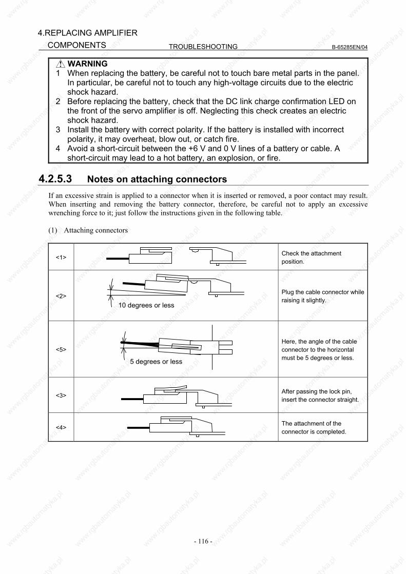
TROUBLESHOOTING B-65285EN/04
- 116 -
4.REPLACING AMPLIFIER COMPONENTS
WARNING 1 When replacing the battery, be careful not to touch bare metal parts in the panel.
In particular, be careful not to touch any high-voltage circuits due to the electric shock hazard.
2 Before replacing the battery, check that the DC link charge confirmation LED on the front of the servo amplifier is off. Neglecting this check creates an electric shock hazard.
3 Install the battery with correct polarity. If the battery is installed with incorrect polarity, it may overheat, blow out, or catch fire.
4 Avoid a short-circuit between the +6 V and 0 V lines of a battery or cable. A short-circuit may lead to a hot battery, an explosion, or fire.
4.2.5.3 Notes on attaching connectors
If an excessive strain is applied to a connector when it is inserted or removed, a poor contact may result. When inserting and removing the battery connector, therefore, be careful not to apply an excessive wrenching force to it; just follow the instructions given in the following table. (1) Attaching connectors
<1>
Check the attachment position.
<2> 10 degrees or less
Plug the cable connector while raising it slightly.
<5>
5 degrees or less
Here, the angle of the cable connector to the horizontal must be 5 degrees or less.
<3>
After passing the lock pin, insert the connector straight.
<4>
The attachment of the connector is completed.
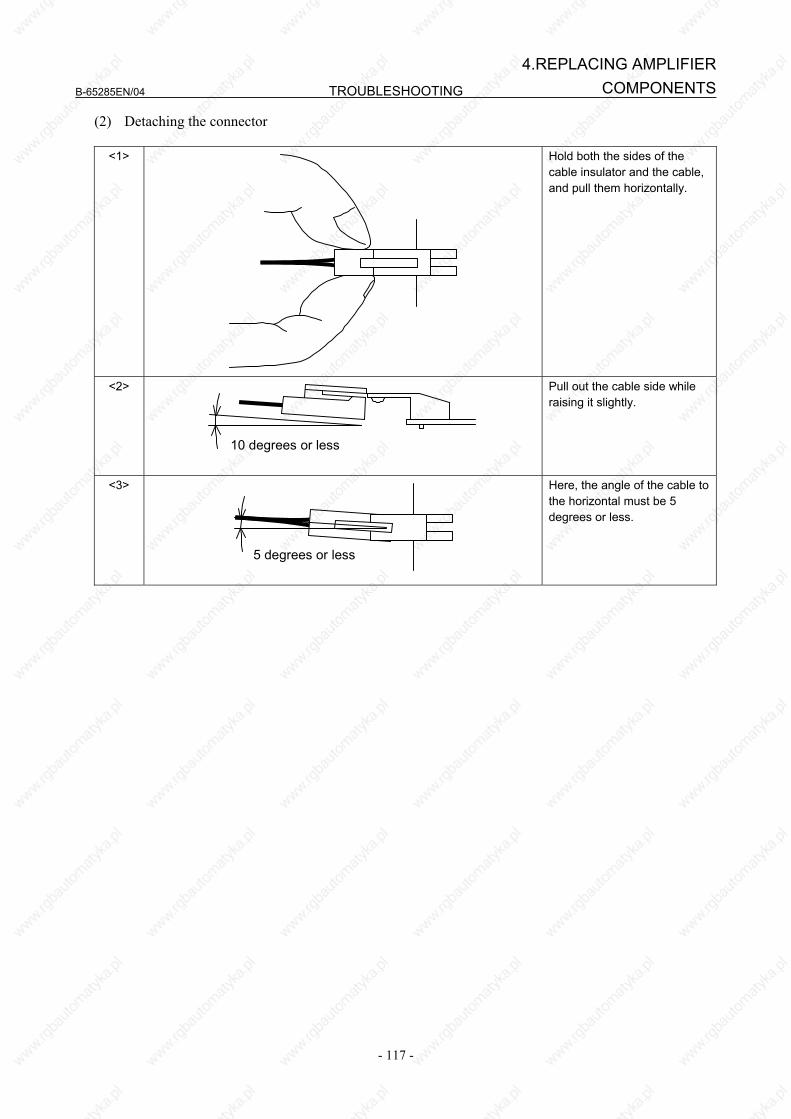
B-65285EN/04 TROUBLESHOOTING
- 117 -
4.REPLACING AMPLIFIERCOMPONENTS
(2) Detaching the connector
<1>
Hold both the sides of the cable insulator and the cable, and pull them horizontally.
<2>
10 degrees or less
Pull out the cable side while raising it slightly.
<3>
5 degrees or less
Here, the angle of the cable to the horizontal must be 5 degrees or less.
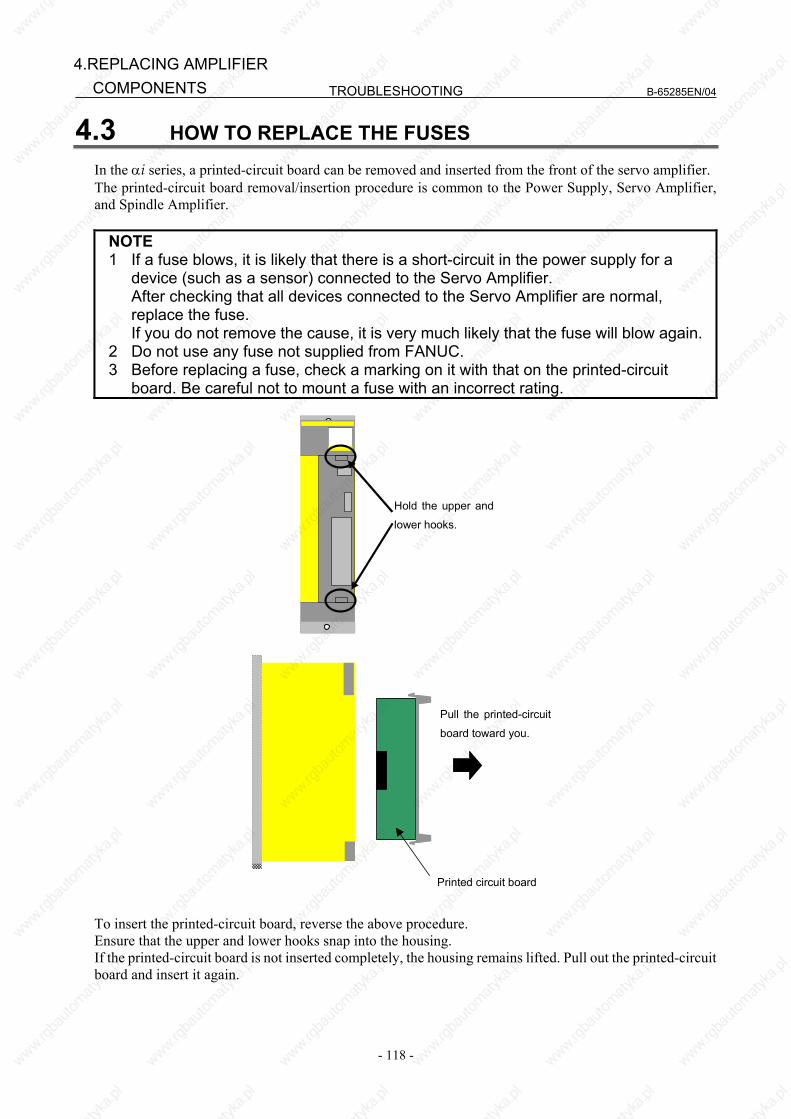
TROUBLESHOOTING B-65285EN/04
- 118 -
4.REPLACING AMPLIFIER COMPONENTS
4.3 HOW TO REPLACE THE FUSES
In the αi series, a printed-circuit board can be removed and inserted from the front of the servo amplifier. The printed-circuit board removal/insertion procedure is common to the Power Supply, Servo Amplifier, and Spindle Amplifier.
NOTE 1 If a fuse blows, it is likely that there is a short-circuit in the power supply for a
device (such as a sensor) connected to the Servo Amplifier. After checking that all devices connected to the Servo Amplifier are normal,
replace the fuse. If you do not remove the cause, it is very much likely that the fuse will blow again. 2 Do not use any fuse not supplied from FANUC. 3 Before replacing a fuse, check a marking on it with that on the printed-circuit
board. Be careful not to mount a fuse with an incorrect rating.
Hold the upper and
lower hooks.
Pull the printed-circuit
board toward you.
Printed circuit board
To insert the printed-circuit board, reverse the above procedure. Ensure that the upper and lower hooks snap into the housing. If the printed-circuit board is not inserted completely, the housing remains lifted. Pull out the printed-circuit board and insert it again.

B-65285EN/04 TROUBLESHOOTING
- 119 -
4.REPLACING AMPLIFIERCOMPONENTS
4.3.1 Fuse Locations
4.3.1.1 Power Supply There are two different fuses on the Power Supply printed-circuit board. Be careful not to confuse their ratings during replacement.
Printed circuit board
Cooling fin
Fan motor
FU1 (5A)
(Rating indicated in red)
FU2 (2A)
(Rating indicated in white)
Fuse specification
Symbol Ordering number FU1 A60L-0001-0359 FU2 A60L-0001-0176/2.0A FU3 A60L-0001-0290/LM32C
4.3.1.2 Servo Amplifier
There is one fuse on the Servo Amplifier printed-circuit board.
FU1 (3.2A)
(Rating indicated in white)
Printed circuit board
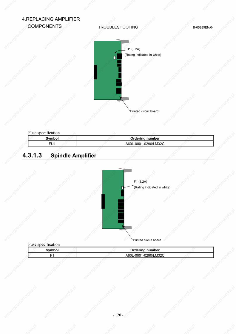
TROUBLESHOOTING B-65285EN/04
- 120 -
4.REPLACING AMPLIFIER COMPONENTS
FU1 (3.2A)
(Rating indicated in white)
Printed circuit board
Fuse specification
Symbol Ordering number FU1 A60L-0001-0290/LM32C
4.3.1.3 Spindle Amplifier
F1 (3.2A)
(Rating indicated in white)
Printed circuit board Fuse specification
Symbol Ordering number F1 A60L-0001-0290/LM32C
III. MOTOR/DETECTOR/AMPLIFIER PREVENTIVE MAINTENANCE

B-65285EN/04
- 123 -
1.MOTOR/DETECTOR/AMPLIFIER
PREVENTIVE MAINTENANCEMOTOR/DETECTOR/AMPLIFIER
PREVENTIVE MAINTENANCE
This chapter describes preventive maintenance of motors, detectors, and amplifiers that is to be performed by the customer the machine uses.
Contents
1 MOTOR/DETECTOR/AMPLIFIER PREVENTIVE MAINTENANCE ...124 1.1 LIST OF MANUALS RELATED TO MOTORS AND AMPLIFIERS............ 124 1.2 PREVENTIVE MAINTENANCE OF MOTORS AND DETECTORS........... 125
1.2.1 Warnings, Cautions, and Notes on Preventive Maintenance of Motors and Detectors...............................................................................................................125
1.2.2 Preventive Maintenance of a Motor (Common to All Models)............................127 1.2.2.1 Main inspection items...................................................................................... 127 1.2.2.2 Periodic cleaning of a motor............................................................................ 130 1.2.2.3 Notes on motor cleaning.................................................................................. 130 1.2.2.4 Notes on the cutting fluid (informational) ....................................................... 130
1.2.3 Routine Inspection of a Spindle Motor with a Through Hole ..............................131 1.2.4 Preventive Maintenance of a Built-in Spindle Motor and Spindle Unit...............131
1.2.4.1 Routine inspection of the FANUC-NSK spindle unit ..................................... 132 1.2.4.2 Maintenance of the FANUC-NSK spindle unit ............................................... 132 1.2.4.3 Test run of the FANUC-NSK spindle unit ...................................................... 133 1.2.4.4 Storage method of the FANUC-NSK spindle unit .......................................... 133
1.2.5 Preventive Maintenance of a Linear Motor..........................................................133 1.2.5.1 Appearance inspection of the linear motor (magnet plate) .............................. 133
1.2.6 Maintenance of a Detector....................................................................................134 1.2.6.1 Alarms for built-in detectors (αi and βi Pulsecoders) and troubleshooting
actions.............................................................................................................. 134 1.2.6.2 Alarms for separate detectors and troubleshooting actions ............................. 135 1.2.6.3 Detailed troubleshooting methods ................................................................... 135 1.2.6.4 Maintenance of βiS motor Pulsecoders ........................................................... 137
1.3 PREVENTIVE MAINTENANCE OF SERVO AMPLIFIERS ....................... 138 1.3.1 Warnings, Cautions, and Notes on Operation of Servo Amplifiers .....................138 1.3.2 Preventive Maintenance of a Servo Amplifier .....................................................141 1.3.3 Maintenance of a Servo Amplifier .......................................................................142
1.3.3.1 Display of the servo amplifier operation status ............................................... 142 1.3.3.2 Replacement of a fan motor............................................................................. 144
1.4 REPLACING BATTERY FOR ABSOLUTE PULSECODERS.................... 145 1.4.1 Overview ..............................................................................................................145 1.4.2 Replacing Batteries...............................................................................................146 1.4.3 Replacing the Batteries in a Separate Battery Case..............................................146 1.4.4 Replacing the Battery Built into the Servo Amplifier ..........................................147
B-65285EN/04
- 124 -
1.MOTOR/DETECTOR/AMPLIFIER
PREVENTIVE MAINTENANCE
MOTOR/DETECTOR/AMPLIFIER
PREVENTIVE MAINTENANCE
1 MOTOR/DETECTOR/AMPLIFIER PREVENTIVE MAINTENANCE
1.1 LIST OF MANUALS RELATED TO MOTORS AND AMPLIFIERS
Details of individual motors and amplifiers are described in the manuals listed in the table below. Before performing periodic inspection or any other maintenance work, consult with the machine tool builder and, if necessary, obtain the latest version of the corresponding manual shown in the list. The information about the specifications of each device, such as the weight and winding resistance value, is given in the relevant "DESCRIPTIONS" manual.
Manual name Type of manual Specification number
FANUC AC SERVO MOTOR αi series DESCRIPTIONS B-65262EN FANUC AC SERVO MOTOR βis series DESCRIPTIONS B-65302EN FANUC SYNCHROUNOUS BUILT-IN SERVO MOTOR DiS series DESCRIPTIONS B-65332EN FANUC LINEAR MOTOR LiS series DESCRIPTIONS B-65382EN FANUC AC SPINDLE MOTOR αi series DESCRIPTIONS B-65272EN FANUC AC SPINDLE MOTOR βi series DESCRIPTIONS B-65312EN FANUC BUILT-IN SPINDLE MOTOR BiI series DESCRIPTIONS B-65292EN FANUC SYNCHROUNOUS BUILT-IN SPINDLE MOTOR BiS series DESCRIPTIONS B-65342EN FANUC - NSK SPINDLE UNIT series DESCRIPTIONS B-65352EN FANUC SERVO AMPLIFIER αi series DESCRIPTIONS B-65282EN FANUC SERVO AMPLIFIER βi series DESCRIPTIONS B-65322EN FANUC AC SERVO MOTOR αi series FANUC AC SERVO MOTOR βi series FANUC LINEAR MOTOR LiS series FANUC SYNCHRONOUS BUILT-IN SERVO MOTOR DiS series
PARAMETER MANUAL B-65270EN
FANUC AC SPINDLE MOTOR αi/βi series BUILT-IN SPINDLE MOTOR Bi series
PARAMETER MANUAL B-65280EN
FANUC AC SERVO MOTOR αis/αi series AC SPINDLE MOTOR αi series SERVO AMPLIFIER αi series
MAINTENANCE MANUAL B-65285EN
FANUC AC SERVO MOTOR βis series AC SPINDLE MOTOR βi series SERVO AMPLIFIER βi series
MAINTENANCE MANUAL B-65325EN
FANUC SERVO AMPLIFIER βi series MAINTENANCE MANUAL B-65395EN FANUC SERVO GUIDE OPERATOR’S MANUAL B-65404EN FANUC AC SERVO MOTOR αis/αi/βis series SERVO TUNING
PROCEDURE (BASIC) B-65264EN
B-65285EN/04
- 125 -
1.MOTOR/DETECTOR/AMPLIFIER
PREVENTIVE MAINTENANCEMOTOR/DETECTOR/AMPLIFIER
PREVENTIVE MAINTENANCE
1.2 PREVENTIVE MAINTENANCE OF MOTORS AND DETECTORS
1.2.1 Warnings, Cautions, and Notes on Preventive Maintenance of Motors and Detectors
This subsection contains the safety precautions for motor and detector preventive maintenance, which are classified into "warnings", "cautions", and "notes" according to their bearing on safety. Make sure that you understand and comply with these precautions when carrying out the maintenance work.
WARNING • Make sure that you are safely dressed and have a safe working environment when
performing preventive maintenance for a motor. - Be dressed safely, e.g. by wearing gloves and safety shoes, to protect against injury due to an
edge or protrusion and electric shock. - Have the work done by more than one person, where possible, so that immediate action can be
taken if an accident occurs when handling a motor. - A motor is heavy. When moving it, use a crane or other appropriate equipment to protect against
injury. For information about the weight of the motor, refer to its DESCRIPTIONS manual (shown earlier).
- Clothes or fingers can be caught in a rotating motor or come into contact with a moving part of it. Standing in the direction of motor rotation (direction of motion) can pose a risk of injury. Before rotating a motor, check that there is no object that is thrown away by motor rotation.
• Be careful about electric shock, fire, and other accidents.
- Do not handle a motor with a wet hand. - To prevent electric shock, make sure that no conductive object, such as a terminal, is exposed
when the motor is powered on. - Before touching a motor or any surrounding part, check that the power is shut off and take
appropriate safety precautions. - High voltage remains across power line terminals of a motor even after the power is shut off (for
at least five minutes). Do not touch a motor in such a condition or connect it to other equipment. - A loose or disconnected terminal, short-circuited terminals, or a terminal connected to the ground
can cause overheating, spark, fire, or damage to the motor. Take appropriate precautions to prevent these accidents.
- When placed near any inflammable object or material, a motor can be ignited, catch fire, or explode. Avoid placing it near such object or material.
• Do not disassemble or modify a motor. Motors such as linear motors, synchronous built-in servo motors, and synchronous built-in spindle
motors contain very strong magnets. If electronic medical apparatus comes near, these motors can cause the apparatus to malfunction, potentially putting the user's life in danger. Also, disassembling or modifying a motor can cause a failure, regardless of the type of motor. Do not disassemble or modify a motor in any way not specified by FANUC.
B-65285EN/04
- 126 -
1.MOTOR/DETECTOR/AMPLIFIER
PREVENTIVE MAINTENANCE
MOTOR/DETECTOR/AMPLIFIER
PREVENTIVE MAINTENANCE
CAUTION • Ensure that the specified cooling conditions are met.
If the specified cooling conditions are not met (the motor is insufficiently or excessively cooled), the motor can fail. Problems that can cause a motor failure, such as liquid piping clog, leakage, and fan motor trouble, should be eliminated through periodic inspection. Do not drive the motor when the cooling system is in an abnormal condition.
• Do not change the system configuration.
Do not change the configuration of the system when it is running normally. Doing so can cause an accident or failure. If you disconnect a cable for maintenance or some other purpose, take an appropriate measure, such as putting a mark on it, to ensure you can restore the original state.
• Use the tapped holes of a motor only to move the motor.
Do not use the tapped holes of a motor to lift or move any other object along with the motor. Doing so can damage the motor. Depending on the type of motor, the place and direction in which the motor can be lifted may be predetermined. For details, refer to the DESCRIPTIONS manual of the motor (shown earlier).
• Do not touch a motor when it is running or immediately after it stops.
A motor may get hot when it is running. Do not touch the motor before it gets cool enough. Otherwise, you may get burned.
NOTE • Do not remove a nameplate from a motor.
The nameplate is used to identify the motor during maintenance work. If a nameplate comes off, be careful not to lose it.
• Do not step or sit on a motor, and avoid applying shock to a motor. Any of these acts can deform or break the motor or affect its component, crippling the normal motor
operation. Do not put a motor on top of another motor. • Comply with the specified conditions when conducting an electric test (winding
resistance test, insulation resistance test, etc.) for a motor or other device or supplying power. - Conduct an electric test according to the specified method. Conducting such a test by any method
that is not specified can damage the motor. - Do not conduct a dielectric strength test or insulation test for a Pulsecoder or other detector, or do
not apply a commercial power source voltage. Doing so can destroy the internal elements.
• Perform preventive maintenance (inspection of the external appearance, measurement of winding resistance, insulation resistance, etc.) and cleaning on a regular basis.
To use a motor safely throughout its entire service life, perform preventive maintenance and cleaning on a regular basis. Be careful, however, because excessively severe inspection (dielectric strength test, etc.) can damage its windings. For information about winding resistance values, refer to the DESCRIPTIONS manual of the motor (its specification number is shown in this manual). Information about insulation resistance is given later in this manual.
B-65285EN/04
- 127 -
1.MOTOR/DETECTOR/AMPLIFIER
PREVENTIVE MAINTENANCEMOTOR/DETECTOR/AMPLIFIER
PREVENTIVE MAINTENANCE
NOTE • This manual is focused on the preventive maintenance work to be performed for a
single FANUC motor or detector alone. The information contained herein may not apply depending on the type or configuration of the machine. When reading this manual, refer to the manual of the machine as well. If you have any questions or doubts, do not act on your own; please contact the machine tool builder or FANUC.
• For detailed information about a motor, see the manual list shown earlier and, if necessary, obtain the latest version of the corresponding manual.
1.2.2 Preventive Maintenance of a Motor (Common to All Models) This subsection describes the common preventive maintenance items to be handled regardless of the model of the motor. For the items specific to a particular motor model, see one of the subsequent subsections that pertains to that particular motor model.
CAUTION • The preventive maintenance method differs from machine to machine in many
respects. Depending on the machine in use, it may be difficult for the user to perform periodic inspection or cleaning. If you are not sure about anything as to preventive maintenance, consult with the machine tool builder and ensure that you can perform periodic inspection and cleaning.
• The machine should be used within the scope of specification defined by the machine tool builder. Using the machine in any way that is outside the specified scope can reduce the motor's service life or cause a failure.
1.2.2.1 Main inspection items
The following table summarizes the main inspection items for a motor. If any of these items is found to be abnormal, stop the use of the machine immediately and fix the abnormal part by repairing or replacing it. At the same time, identify and remove the cause and take a measure to prevent its recurrence. If it is difficult to take a preventive measure or to prevent its recurrence, consult with the machine tool builder or FANUC.
Crack or deformation
- Check the motor for any scar, crack, deformation, bulge, etc. - If the interior of the motor is visible or there is interference with a
peripheral component, it is imperative to replace the motor or the peripheral component.
- A light peel-off or scar of the surface may be repairable; consult with FANUC.
Appearance of the motor
Wet or dirty part - If you find any wet or dirty part, clean it immediately. - A preventive measure is needed if the part in question remains wet
continually due to cutting fluid or dew condensation. Operating conditions
Temperature, humidity, etc.
- Comply with the operating conditions of the machine. For details of the operating conditions of a specific motor, refer to the corresponding DESCRIPTIONS manual. Generally, the ambient temperature should be 0°C to 40°C (or 30°C for a spindle unit) and dew condensation is not allowed. In a place subject to severe vibration, the components of the motor may be broken.
B-65285EN/04
- 128 -
1.MOTOR/DETECTOR/AMPLIFIER
PREVENTIVE MAINTENANCE
MOTOR/DETECTOR/AMPLIFIER
PREVENTIVE MAINTENANCE
Cable - Check for any cable sheath damage, exposed conductor, damaged conduit or cable bearing, abnormal bending, loose terminal, etc.
- If there is any trace of fluid flowing, the fluid may have entered the inside of the motor or connector. It is necessary to make a check and take a measure to prevent recurrence.
Connection state
Connector/terminal - Check for any cracked, exposed, loose, or removed terminal or connector, etc.
- Fluid causes a failure; be sure to remove fluid. - A scarred or damaged connector or terminal needs to be replaced. In the
case of a resin molded motor, such as a linear motor, the motor needs to be replaced.
Noise/vibration - Check for any abnormal noise or vibration not only when the motor is running (the spindle is rotating) but also when it is stopped.
- Abnormal noise heard when the motor is rotating indicates an abnormality of the bearing or a failure inside the motor.
- If abnormal noise is generated from the connection section of a Spindle Amplifier, check the following items: Belt connection: Check whether the belt tension is appropriate. Gear connection: Check whether an appropriate value is set for the gear
backlash. Coupling connection: Check whether the coupling is free from
deformation, crack, and looseness. Movement - Check that the motor operates normally and smoothly.
- If the circuit breaker trips at the same time the motor starts to operate, it indicates abnormal motor windings.
Operation of the motor
Heat Check whether the motor does not overheat during the normal operation cycle. Note: While the motor is running or immediately after it is stopped, the motor surface may become very hot. Instead of touching the motor directly by hand, use a thermolabel, surface thermometer, etc.
Winding resistance If the resistance value exceeds the specified range, the motor needs to be replaced. Note: When conducting winding resistance measurement, disconnect the motor from the amplifier and measure the resistance at the power line or connector closest to the motor.
Electric characteristics of the motor
Insulation resistance
For the measuring method and judgment criteria, see the table that follows.
Noise/vibration - Check that the fan blows air normally without causing abnormal noise or vibration.
- If abnormal noise is heard even when the motor is stopped, it indicates a fan motor failure.
Cooling fan (for a model with a fan motor)
Movement - If the power is on and if the fan does not operate or the fan blades cannot be moved even manually, or if the fan blades are rotating but no cooling wind is blown out, the fan motor may have cutting chips or sludge accumulated in it and needs to be cleaned.
- If the fan does not operate normally for any other reason, the fan motor needs to be replaced.
B-65285EN/04
- 129 -
1.MOTOR/DETECTOR/AMPLIFIER
PREVENTIVE MAINTENANCEMOTOR/DETECTOR/AMPLIFIER
PREVENTIVE MAINTENANCE
Dew condensation (over-cooling)
- Check that forcible cooling does not cause dew condensation on the motor surface. Dew condensation is likely particularly when the cooling unit continues to run after the machine is stopped. In that case, be sure to make this check.
- Dew condensation or water drop on the motor surface can reduce the motor's service life. It is necessary to wipe it dry and take a measure to prevent recurrence.
Forcible cooling unit (when using an external cooling unit such as liquid cooling unit)
Liquid leakage/clog
- Check the cooling pipe for leakage or clog. Do not drive the motor unless the leakage or clog is fixed.
- Liquid leakage from a spindle motor with a through hole indicates a failure of the coolant joint. In this case, the joint needs to be replaced.
- In the case of liquid leakage from a linear motor (coil slider), the linear motor (coil slider) needs to be replaced.
- If the motor gets wet due to liquid leakage or any other cause, it is necessary to clean and dry the motor and perform electric characteristic checks (winding resistance/insulation resistance).
Insulation resistance measurement
The following table shows the judgment criteria to be applied when measuring insulation resistance between winding and frame using a megohmmeter (500 VDC).
Insulation resistance Judgment 100M Ω or higher Acceptable
10M to 100M Ω The winding has begun deteriorating. There is no problem with the performance at present. Be sure to perform periodic inspection.
1M to 10M Ω The winding has considerably deteriorated. Special care is in need. Be sure to perform periodic inspection.
Lower than 1M Ω Unacceptable. Replace the motor. If insulation resistance drops sharply during a short period of time or if the circuit breaker trips, the cutting fluid or other foreign matter may have entered the inside of the motor or cable. In that case, contact the machine tool builder or FANUC for instructions.
CAUTION • Let the motor dry and cool to room temperature before winding or insulation
resistance is measured. Otherwise, not only an accurate measurement cannot be performed but also the motor may be damaged.
• The winding or insulation resistance measurement should be performed on the motor alone, with its power line disconnected. Measuring insulation resistance with the motor connected to the amplifier may damage the amplifier.
• During insulation resistance measurement, applying voltage to the motor for a long time may further deteriorate the insulation of the motor. Therefore, the measurement of insulation resistance should be performed in a minimum amount of time where possible.
• When disconnecting the power line and other cables, take an appropriate measure, such as labeling, to ensure that they can be restored to their original state.
B-65285EN/04
- 130 -
1.MOTOR/DETECTOR/AMPLIFIER
PREVENTIVE MAINTENANCE
MOTOR/DETECTOR/AMPLIFIER
PREVENTIVE MAINTENANCE
1.2.2.2 Periodic cleaning of a motor Periodic cleaning is necessary to remove an accumulation of cutting chips or sludge that may eventually cause a failure. Also, leaving the cutting fluid or other chemical substance attached for a long time can reduce the motor's service life substantially. When forcible cooling is provided by a liquid or air cooling unit, check the unit for pipe clog, fan failure, etc. and perform cleaning periodically to ensure that the coolant flows smoothly and that the motor is cooled properly.
WARNING Depending on the type of motor, the handling may involve a risk and require safety
education in advance. Also, some machines are difficult for users to clean on their own. If you are to clean the motor, consult with the machine tool builder in advance with regard to the cleaning method, safety education, etc.
1.2.2.3 Notes on motor cleaning
A motor is an electric product, which is incompatible with most kinds of fluid. When removing cutting chips, sludge, cutting fluid, etc. during cleaning, note the following.
Note on cleaning Measure
Do not sprinkle fluid. Do not wash by submerging.
Do not sprinkle or spray detergent or any other fluid over the motor (including its peripheral components), or do not wash the motor by submerging it in such fluid. When cleaning the motor, use a cloth moistened with a small amount of neutral detergent so that the fluid does not enter the inside the motor.
Do not use solvent.
Solvent may damage the motor; do not use one. If the dirt is difficult to remove with neutral detergent, use a cloth moistened with a small amount of industrial alcohol (e.g., IPA). Be careful, however, because rubbing with force or repeatedly may damage the coated or resin surface.
Do not leave the motor wet or moistened.
If the motor is wet or moistened after cleaning, dry it before supplying power and before performing electric tests. When drying the motor in an oven, make sure that the temperature is below 40°C and that hot air does not blow directly against the motor.
1.2.2.4 Notes on the cutting fluid (informational)
Depending on the type of cutting fluid used, the motor and amplifier may be affected greatly. Take due care because, even if you ensure that they do not come into direct contact with the fluid, a mist or atmosphere of the fluid can cause the problems described below.
Type of cutting fluid requiring care
Expected problem
Cutting fluid containing highly active sulfur
Some types of cutting fluid contain highly active sulfur. If such cutting fluid enters the inside of the motor or amplifier, it causes copper, silver, and other kinds of metal to corrode, leading to a component failure.
Synthetic cutting fluid with high permeability
Some types of cutting fluid containing such substance as polyalkylene glycol have very high permeability. Such cutting fluid permeates into the inside of the motor, causing insulation deterioration or component failure.
Highly alkaline, water-soluble cutting fluid
Some types of cutting fluid that enhance their alkaline property using such substance as alkanolamine remain highly alkaline - pH10 or higher - when diluted. If such cutting fluid is left attached for a long time, its chemical change will deteriorate the resin and other materials of the motor and amplifier.
Other types of cutting fluid not mentioned above may cause various unexpected problems. If any problem arises for which the cutting fluid is thought to be responsible, consult with the machine tool builder or FANUC.

B-65285EN/04
- 131 -
1.MOTOR/DETECTOR/AMPLIFIER
PREVENTIVE MAINTENANCEMOTOR/DETECTOR/AMPLIFIER
PREVENTIVE MAINTENANCE
1.2.3 Routine Inspection of a Spindle Motor with a Through Hole • Check whether coolant does not always leak from the drain on the rotation joint support housing. (See
Fig. 2) • Check whether coolant does not always leak from the notch on the rotation joint support housing. (See
Fig. 2) • Check whether coolant leaking from the coolant joint does not leak from the coupling. (See Fig. 3) • Check whether leaking coolant is not collected in the coupling box.
Rotation joint support housing Coupling
Fig. 1: Example of using a coolant-through spindle motor
Coolant joint
φdφd
凸タイプ 凹タイプ
Fig. 3: Example of a coolant joint
Drain
Spare drain Notch
Rotation joint support housing
Fig. 2: Rotation joint support housing
Convex type Concave type
1.2.4 Preventive Maintenance of a Built-in Spindle Motor and Spindle Unit
This subsection contains the safety precautions you need to bear in mind when performing preventive maintenance for a built-in spindle motor (BiI or BiS Series) or the FANUC-NSK spindle unit. In some cases, the work may involve a life-threatening risk or cause substantial damage. Make sure that you fully understand these safety precautions before carrying out the work.
B-65285EN/04
- 132 -
1.MOTOR/DETECTOR/AMPLIFIER
PREVENTIVE MAINTENANCE
MOTOR/DETECTOR/AMPLIFIER
PREVENTIVE MAINTENANCE
WARNING • Do not disassemble the spindle. Particularly, the rotor of a synchronous built-in
spindle motor (BiS Series) uses strong permanent magnets. The strong magnet force may cause injury or medical appliance malfunction.
• Do not operate a synchronous built-in spindle motor with an external engine. Doing so is very dangerous because it makes the motor act as a power generator, generating high voltage. A power outage is also dangerous because the motor runs freely and, again, generates high voltage. As a safety precaution, a sub module SM (SSM) is connected between motor and amplifier. Do not disconnect the SSM under any circumstances. Also, connect the machine frame to the ground to prevent electric shock.
• A synchronous built-in spindle motor may perform a pole position detection operation when it receives the first rotation command after it is powered on or recovers from an alarm. The pole position detection operation takes 20 to 60 seconds to complete, during which the spindle behaves oddly, e.g., rotating clockwise and counterclockwise alternately in rapid succession. This phenomenon is not abnormal. During the detection operation, do not touch or look down at the spindle, which is a dangerous act.
CAUTION
Performing a test run described in Chapter 3, "TEST RUN METHOD", in Part IV, of "FANUC - NSK SPINDLE UNIT series DESCRIPTIONS (B-65352EN)" and the inspection and maintenance work described in this manual is the condition for guaranteeing the operation of the FANUC-NSK spindle unit. Be sure to perform the test run and inspection and maintenance work as instructed.
1.2.4.1 Routine inspection of the FANUC-NSK spindle unit
Perform the following routine inspections every day at the start of operation so that stable performance can be obtained from the spindle.
Item Check 1 Check if the axis, when turned manually, rotates lightly and smoothly.
WARNING When turning the axis manually, be sure to turn off the power to the machine.
2 Check if cuttings and coolant residuals are attached to the periphery of a slinger. 3 Check if dust such as cuttings is attached to the spindle taper portion. 4 For operation at 15,000 min-1 or more immediately after power-up, increase the speed gradually
by using the spindle override function. (This substitutes for a simple test run.)
5 Check if an abnormal sound is generated. 6 Check if an abnormal vibration is generated. 7 Check if an abnormal heat is generated.
1.2.4.2 Maintenance of the FANUC-NSK spindle unit
A FANUC-NSK spindle unit with a grease unit requires periodical maintenance for consumable/wear parts, such as supplying grease. Depending on the use frequency of and damage to parts, maintenance generally becomes necessary after two years of machine operation or 10,000 hours of spindle operation. Contact FANUC or the machine tool builder when maintenance becomes necessary. Also, an effective way to reduce the machine down time due to maintenance is to prepare spare parts; consult with the machine tool builder.
B-65285EN/04
- 133 -
1.MOTOR/DETECTOR/AMPLIFIER
PREVENTIVE MAINTENANCEMOTOR/DETECTOR/AMPLIFIER
PREVENTIVE MAINTENANCE
1.2.4.3 Test run of the FANUC-NSK spindle unit If any of the following cases applies, be sure to contact the machine tool builder and perform a test run as described in Chapter 3, "TEST RUN METHOD", in Part IV, of "FANUC - NSK SPINDLE UNIT series DESCRIPTIONS (B-65352EN)". - If the spindle unit is rotated for the first time after it is unpacked or attached to the machine - If the machine or spindle unit has undergone transportation or relocation - If the spindle unit alone has been stored for a period longer than six months or has not been used for
one month or more after installation
CAUTION FANUC assumes no responsibility for any damage resulting from the failure to perform a test run or improper use of the spindle unit.
1.2.4.4 Storage method of the FANUC-NSK spindle unit
Apply rust-proof oil to the surface of the spindle unit, pack the spindle unit, and store the packed spindle unit at a location that satisfies the conditions described below. Also, follow the "This Side Up" and "No Pile Up" instructions indicated on the pack surface. - Indoor well ventilated place not exposed to direct sunlight (place where the temperature varies little,
the room temperature is within 5°C to 40°C, and the humidity is 35% to 85% RH) - Place on the shelf subject to little vibration and dust (Do not place the spindle unit directly on the floor;
vibration and dust can damage the bearing or other parts of the spindle.) Before using the spindle unit after a storage period of one month or more, make necessary checks, such as measuring winding and insulation resistance, examining the appearance for rust and other problems, and checking whether the axis can be turned manually. Depending on the storage period, a test run may be necessary (described earlier).
1.2.5 Preventive Maintenance of a Linear Motor The magnet plate of a linear motor contains very strong magnets. When performing the maintenance work, make sure all those engaged in the work fully understand the potential risks involved.
WARNING • The FANUC linear motors use very strong magnets. Improper handling of the
motor is very dangerous and can lead to a serious accident. Particularly, a person wearing a pacemaker or other medical apparatus should stay away from the linear motor; otherwise, the apparatus may malfunction, potentially resulting in a life-threatening accident.
• Those who will come near or touch a linear motor for maintenance work should receive safety education in advance. For details, contact the machine tool builder or FANUC.
1.2.5.1 Appearance inspection of the linear motor (magnet plate)
Perform an appearance inspection as well during cleaning or other maintenance work. A crack, chip, deformation, or any other abnormality in appearance of the motor can lead to a serious failure in the not-so-distant future. If you find any such abnormality, be sure to report it to the machine tool builder. A scratch or other slight scar on the motor surface can also be a sign of future trouble and needs to be addressed with care. Some suggested appearance inspection items for the magnet plate are described below.

B-65285EN/04
- 134 -
1.MOTOR/DETECTOR/AMPLIFIER
PREVENTIVE MAINTENANCE
MOTOR/DETECTOR/AMPLIFIER
PREVENTIVE MAINTENANCE
* For the coil slider (the side to which the power line is connected), see "Main inspection items" earlier in this manual.
Appearance of the magnet plate (which may have a stainless cover)
Appearance inspection item Measure Crack or chip in the magnet plate resin Deformation or bulge of the magnet plate or softening of the resin
The magnet plate needs to be replaced. If unattended, it can cause trouble in the not-so-distant future. If the problem is extremely minor, consult with the machine tool builder or FANUC.
The magnet is exposed, or the resin or magnet is floating
The magnet plate needs to be replaced urgently.
Scratch on the magnet plate Foreign matter may have entered into the motor, or interference between parts is likely. It is necessary to eliminate the cause and take a measure to prevent recurrence.
Floating, bulging, or deformed stainless cover
The cover or magnet plate needs to be replaced.
1.2.6 Maintenance of a Detector
CAUTION • Detectors such as Pulsecoders are precision equipment. When handling a
detector, avoid applying shock to it. Also, exercise care to prevent cutting powder, dust, cutting fluid, or other foreign matter from attaching to it.
• Make sure that all connectors are connected properly and securely. A connection failure can cause an alarm or some other problem.
• If the detector and/or connectors are not installed securely, cutting fluid may enter the inside of the detector, making it necessary to replace the detector. In that case, contact the machine tool builder or FANUC.
NOTE
If you use a detector not manufactured by FANUC, contact the machine tool builder or detector manufacturer for detailed information on the detector.
1.2.6.1 Alarms for built-in detectors (αi and βi Pulsecoders) and
troubleshooting actions These alarms concern built-in detectors that are connected directly to the control unit (CNC/servo amplifier). Based on the alarm number and description, take an appropriate action as described in the following subsection, "Detailed troubleshooting methods".
Alarm No.: Alarm Description Possible cause Action Detailed
troubleshooting method
361: ABNORMAL PHASE DATA(INT)
- Communication error in the Pulsecoder
- ID data error
- Pulse coder failure - Noise
Replace the Pulsecoder.
(3) (4)
364: SOFT PHASE ALARM(INT)
Position data alarm - Noise - Entry of cutting fluid
Check the effect of noise. Replace the Pulsecoder.
(1) (3)
365: BROKEN LED(INT) LED disconnection - Pulse coder failure Replace the Pulsecoder.
(3)
B-65285EN/04
- 135 -
1.MOTOR/DETECTOR/AMPLIFIER
PREVENTIVE MAINTENANCEMOTOR/DETECTOR/AMPLIFIER
PREVENTIVE MAINTENANCE
Alarm No.: Alarm Description Possible cause Action Detailed
troubleshooting method
366: PULSE MISS(INT) Small internal signal amplitude
- Pulse coder failure - Noise
Replace the Pulsecoder.
(3) (4)
367: COUNT MISS(INT) Position data count error
- Pulse coder failure - Noise
Replace the Pulsecoder.
(3) (4)
368: SERIAL DATA ERROR(INT)
Communication interruption
- Cable disconnection- Pulse coder failure - Noise
Check the cable. Replace the Pulsecoder.
(2) (3) (4)
369: DATA TRANS. ERROR(INT)
Communication data alarm
- Noise Check the effect of noise.
(1)
453: SPC SOFT DISCONNECT ALARM
Position - pole data error
- Pulse coder failure - Entry of cutting fluid
Replace the Pulsecoder.
(3)
1.2.6.2 Alarms for separate detectors and troubleshooting actions
These alarms concern separate detectors that are connected to the control unit via a separate detector interface unit (SDU). Based on the alarm number and description, take an appropriate action as described in the following subsection, "Detailed troubleshooting methods".
Alarm No.: Alarm Description Possible cause Action Detailed
troubleshooting method
380: BROKEN LED(EXT) LED disconnection
382: COUNT MISS(EXT)Position data count error
383: PULSE MISS(EXT) Small internal signal amplitude
384: SOFT PHASE ALARM(EXT)
Position data alarm
- Detector failure Replace the detector.
(4)
385: SERIAL DATA ERROR(EXT)
Communication interruption
- Cable disconnection - Noise - Detector failure
Check the cable. Check the effect of noise. Replace the detector.
(2) (1) (4)
386: DATA TRANS. ERROR(EXT)
Communication data alarm
- Noise Check the effect of noise.
(1)
381: ABNORMAL PHASE (EXT) 387: ABNORMAL ENCODER(EXT)
For details, contact the machine tool builder or detector manufacturer.
1.2.6.3 Detailed troubleshooting methods
(1) Checking the effect of noise Check CNC diagnosis information No.356 (Built-in detector), No.357 (Separate detector). Normally, 0 is displayed. However, if the position data from the Pulsecoder becomes unstable due to noise or some other factor, this value is incremented. The value is cleared when the CNC unit is powered off. Immediately after the power is turned on, 0 is displayed.
(2) Checking the cable Check whether the feedback cable is not disconnected and whether the connector is properly plugged.
B-65285EN/04
- 136 -
1.MOTOR/DETECTOR/AMPLIFIER
PREVENTIVE MAINTENANCE
MOTOR/DETECTOR/AMPLIFIER
PREVENTIVE MAINTENANCE
(3) Replacing the Pulsecoder
(3)-1 Pulse coder replacement procedure <1> Remove the four M4 hexagon socket head cap
screws fastening the Pulsecoder. The M3 bolts fastening the Pulsecoder cover do not need to be loosed. (See the figure at right.)
<2> Remove the Pulsecoder and Oldham's coupling
(see the following figure).
<3> Set the new Pulsecoder and Oldham's coupling on the motor. Adjust the direction of the mate Oldham's coupling to that of the Oldham's coupling so that the teeth are engaged.
Push in the Pulsecoder until the O ring fits in the
joint between the motor and Pulsecoder. Take care so that the O ring of the Pulsecoder is not bitten.
Attach the Pulsecoder in such a direction that the power connector of the servo motor and the feedback cable of the Pulsecoder face the same direction or that the thermistor connection parts of the servo motor and Pulsecoder match each other (see the figure at left).
<4> Fastening the Pulsecoder with the four M4 hexagon socket head cap screws. (Appropriate torque: 1.5
Nm)
(3)-2 Feedback cable plugging procedure Plug in the feedback cable connector, as instructed in the procedure below, and check that the connector is securely connected. <1> Check the plugging side and key direction. Check that the plugging side is free of foreign matter,
such as dirt or oil. <2> Plug in the feedback cable connector. Hold the connector, as shown in the figure at
right. Plug in the connector until you hear a click.
Bolt fastening the Pulsecoder cover M3
× Do not loosen
Remove
Main key
Coupling nut
Straight type Right angle type
Caution) Do not hold the coupling nut.
Oldham's coupling
Mate Oldham's coupling
O ring
Adjust the connector direction
Bolt fastening the Pulsecoder M4
Adjust the connection parts
Thermistor connector
Pulse coder Servo motor

B-65285EN/04
- 137 -
1.MOTOR/DETECTOR/AMPLIFIER
PREVENTIVE MAINTENANCEMOTOR/DETECTOR/AMPLIFIER
PREVENTIVE MAINTENANCE
<3> Check the connection condition. 1. Check that the arrow mark of the
connector is at the center, as shown in the figure at right. If the arrow mark is not at the center, turn the coupling nut manually until the mark comes to the appropriate position.
2. Hold the connector by the same part as in <2>, and pull it lightly to check that the connector does
not come off. Do not pull the cable.
(4) If troubleshooting is difficult for the user If the problem is difficult for the user to troubleshoot because it is due to a detector failure or noise, consult with the machine tool builder or FANUC.
1.2.6.4 Maintenance of βiS motor Pulsecoders Problems concerning the Pulsecoders of the motors listed in the table below require the maintenance (replacement) of the entire motor (it is not possible to maintain the Pulsecoder alone).
Motor model Motor specification Remarks βiS 0.2/5000 A06B-0111-Bx03 βiS 0.3/5000 A06B-0112-Bx03
x=1,2,4,5
βiS 0.4/5000 A06B-0114-Bx03#0y00 βiS 0.5/6000 A06B-0115-Bx03#0y00 βiS 1/6000 A06B-0116-Bx03#0y00
x=1,2,4,5 y=0,1
1m
m o
r les
s
B-65285EN/04
- 138 -
1.MOTOR/DETECTOR/AMPLIFIER
PREVENTIVE MAINTENANCE
MOTOR/DETECTOR/AMPLIFIER
PREVENTIVE MAINTENANCE
1.3 PREVENTIVE MAINTENANCE OF SERVO AMPLIFIERS
1.3.1 Warnings, Cautions, and Notes on Operation of Servo Amplifiers
This subsection contains the safety precautions on preventive maintenance of a servo amplifier (a generic term to refer to the power supply, servo amplifier, spindle amplifier, and other sub modules of a motor drive unit). These precautions are classified into "warnings", "cautions", and "notes" according to their bearing on safety. Make sure that you understand and comply with these precautions when carrying out the maintenance work.
WARNING • Make sure that you are safely dressed and have a safe working environment when
performing preventive maintenance for a servo amplifier. - Be dressed safely, e.g. by wearing gloves and safety shoes, to protect against injury due to an
edge or protrusion and electric shock. - Have the work done by more than one person, where possible, so that immediate action can be
taken if an accident occurs when handling a motor. - A servo amplifier and AC reactor contain heavy components. Be careful when transporting them
or mounting them on the power magnetic cabinet. Also be careful not to get your fingers caught between the power magnetics cabinet and servo amplifier.
• Before turning on the power, check that the door of the power magnetics cabinet and
all other doors. - Ensure that the door of the power magnetics cabinet containing the servo amplifier, as well as all
other doors, are closed and locked except during maintenance work. • When the need arises to open the door of the power magnetics cabinet, only a person
trained in the maintenance of the corresponding machine or equipment should do the task after shutting off the power supply to the power magnetics cabinet by opening both the input circuit breaker of the power magnetics cabinet and the factory switch used to supply power to the cabinet.
• Be careful about electric shock, fire, and other accidents.
- If the machine must be operated with the door open for adjustment or some other purpose, the operator must keep his or her hands and tools well away from any dangerous voltages. Such work must be done only by a person trained in the maintenance of the machine or equipment.
- Ensure that the door of the power magnetics cabinet is locked so that the door cannot be opened by anyone, except service personnel or a qualified person trained in maintenance to prevent electric shock, when the servo amplifier is powered on.
- When the need arises for an operator to open the door of the power magnetics cabinet and perform an operation, ensure that the operator is sufficiently educated in safety or that a protective cover is added to prevent the operator from touching any dangerous part.
- The servo amplifier contains a large-capacity electrolytic capacitor in it and remains charged for a while after the power is shut off. Before touching the servo amplifier for maintenance or some other purpose, measure the residual voltage of the DC link connection using a tester and check that the red LED for indicating charging is in progress is not lit, in order to ensure safety.
- After wiring, be sure to close the servo amplifier cover.
B-65285EN/04
- 139 -
1.MOTOR/DETECTOR/AMPLIFIER
PREVENTIVE MAINTENANCEMOTOR/DETECTOR/AMPLIFIER
PREVENTIVE MAINTENANCE
- A loose screw or poor connector contact can cause a motor malfunction or overheating, connection to ground, or short-circuit. Be extremely careful with power supply lines, motor power lines, and DC link connections through which a large electric current flows, because a loose screw or poor connector contact may lead to a fire. Tighten screws and connectors using the specified screw tightening torque.
- The surfaces of the regenerative discharge unit and heat radiator may become very hot. Do not touch them directly by hand.
• When operating the machine for the first time after preventive maintenance, check
that the machine operates as instructed. - To check whether the machine operates as instructed, first specify a small value for the motor and
then increase the value gradually. If the motor operates abnormally, perform an emergency stop immediately.
- When pressing the emergency stop button, check that the motor stops immediately and that the power being supplied to the amplifier is shut off by the magnetic contactor.
• Notes on alarms
- If the machine stops due to an alarm, check the alarm number. Depending on the alarm issued, if the power is supplied without replacing the failed component, another component may be damaged, making it difficult to identify the original cause of the alarm.
- Before resetting an alarm, ensure that the original cause of the alarm has been removed. • If the motor causes any abnormal noise or vibration while operating, stop it
immediately. - Using the motor in spite of the abnormal noise or vibration may damage the servo amplifier.
• Do not disassemble or modify a servo amplifier. Do not disassemble or modify a servo amplifier in any way not specified by FANUC; doing so can
lead to a failure.
CAUTION • Notes on servo amplifier replacement and wiring
- The work of servo amplifier replacement and wiring should be carried out by a person trained in the maintenance of the machine and equipment concerned.
- When replacing a servo amplifier, check that the combination of the amplifier and the motor is appropriate.
- Check that the servo amplifier is securely mounted on the power magnetics cabinet. If there is any clearance between the power magnetics cabinet and the surface on which the amplifier is mounted, dust entering the gap may hinder the normal operation of the servo amplifier.
- Ensure that the power supply lines, motor power lines, and signal lines are each connected to the correct terminal or connector.
- Unless otherwise instructed, do not unplug a connector and plug it back with the power on; doing so may cause the servo amplifier to fail.
- When mounting or unmounting the servo amplifier, exercise care not to get your fingers caught between the servo amplifier and power magnetics cabinet.
- Take care not to lose track of removed screws. Turning on the power with any lost screw left in the unit may damage the machine.
- Exercise care to prevent the power supply lines and motor power lines from being connected to the ground or being short-circuited.
- Protect the lines from any stress such as bending. Handle the line ends appropriately.
B-65285EN/04
- 140 -
1.MOTOR/DETECTOR/AMPLIFIER
PREVENTIVE MAINTENANCE
MOTOR/DETECTOR/AMPLIFIER
PREVENTIVE MAINTENANCE
• Be careful about the handling of a servo amplifier. - Do not disassemble a servo amplifier. Doing so poses the risk of electric shock, because the
capacitor may remain charged. - Do not apply shock to a servo amplifier. Doing so may damage its components, potentially
causing the amplifier to malfunction. - Do not apply an excessively large force to plastic parts. If a plastic section breaks, it may damage
internal parts, thus hindering normal operation or leading to a risk of injury due to a broken section.
• Be careful about the operating environment of a servo amplifier.
- Prevent conductive, combustible, or corrosive foreign matter, mist, or drops of water from entering the inside of the unit. The entry of any such material may cause the unit to explode, break, malfunction, etc.
- Exercise care to prevent cutting fluid, oil mist, cutting chips, or other foreign matter from attaching to the radiator or fan motor exposed to the outside of the power magnetics cabinet. Otherwise, the servo amplifier may become unable to meet its specifications. The service lives of the fan motor and semiconductors can also be reduced.
• Clean the heat sink and fan motor on a regular basis.
- Replace the filter of the power magnetics cabinet on a regular basis. - Before cleaning the heat sink, shut down the power and ensure that the temperature of the heat
sink is as cool as the room temperature. The heat sink is very hot immediately after power shutdown, touching it may cause burn injury.
- When cleaning the heat sink by blowing air, be careful about dust scattering. Conductive dust attached to the servo amplifier or its peripheral equipment can lead to a failure.
NOTE • Make sure that there is sufficient maintenance clearance around the doors of the
machine and equipment. • Do not step or sit on the servo amplifier, or do not apply shock to it. • Do not remove a nameplate from a motor.
- The nameplate is necessary to identify the servo amplifier during maintenance work. - If a nameplate comes off, be careful not to lose it.
NOTE • This manual is focused on the preventive maintenance work to be performed for a
FANUC servo amplifier. The information contained herein may not apply depending on the type or configuration of the machine. When reading this manual, refer to the manual of the machine as well. If you have any questions or doubts, do not act on your own; please contact the machine tool builder or FANUC.
• For detailed information about a servo amplifier, see the manual list shown earlier and, if necessary, obtain the latest version of the corresponding manual.

B-65285EN/04
- 141 -
1.MOTOR/DETECTOR/AMPLIFIER
PREVENTIVE MAINTENANCEMOTOR/DETECTOR/AMPLIFIER
PREVENTIVE MAINTENANCE
1.3.2 Preventive Maintenance of a Servo Amplifier To use a servo amplifier safely throughout its entire service life, perform daily and periodic inspections.
CAUTION • The preventive maintenance method differs from machine to machine in many
respects. Depending on the machine in use, it may be difficult for the user to perform periodic inspection or cleaning. If you are not sure about anything as to preventive maintenance, consult with the machine tool builder and ensure that you can perform periodic inspection and cleaning.
• The machine should be used within the scope of specification defined by the machine tool builder. Using the machine in any way that is outside the specified scope can reduce the servo amplifier's service life or cause a failure.
Inspection interval Inspection
part Inspection item
Routine PeriodicJudgment criterion
Ambient temperature
V Around the power magnetics cabinet: 0°C - 45°C Inside the power magnetics cabinet: 0°C - 55°C
Humidity V 90% or below RH (dew condensation not allowed)
Dust/oil mist V There shall be no dust or oil mist attached near the servo amplifier.
Cooling air path V The cooling fan shall be operating normally without the air flow being interrupted.
Abnormal vibration/noise
V
- No abnormal noise or vibration shall be present that has not been experienced in the past.
- Vibration near the servo amplifier shall be 0.5 G or less.
Operating environment
Supply voltage V 200-V input type: Within 200 - 240 V 400-V input type: Within 400 - 480 V
General V There shall be no abnormal noise or smell, and there shall be no dust or oil mist attached.
Screw V There shall be no loose screw.
Fan motor (NOTE 1, 2) V - There shall be no abnormal vibration or noise,
and the fan blades shall be rotating normally. - There shall be no dust or oil mist attached.
Connector V There shall be no loose or broken connector.
Servo amplifier
Cable V There shall be no sign of overheating or sheath deterioration (discoloration pr crack).
CNC Absolute (NOTE 2) Pulse coder battery
V The machine operator's panel or screen shall not display the alarm indicating the battery voltage of the absolute Pulsecoder is low.
Magnetic contactor V The contactor shall not rattle or chatter. Ground fault interrupter
V The interrupter shall be able to trip. External
equipment AC reactor V There shall be no hum.
NOTE 1 Fan motors are periodic-replacement parts. It is recommended to inspect fan
motors on a routine basis and replace them in a preventive manner. 2 Fan motors and batteries are periodic-replacement parts. It is recommended to
keep spare parts.
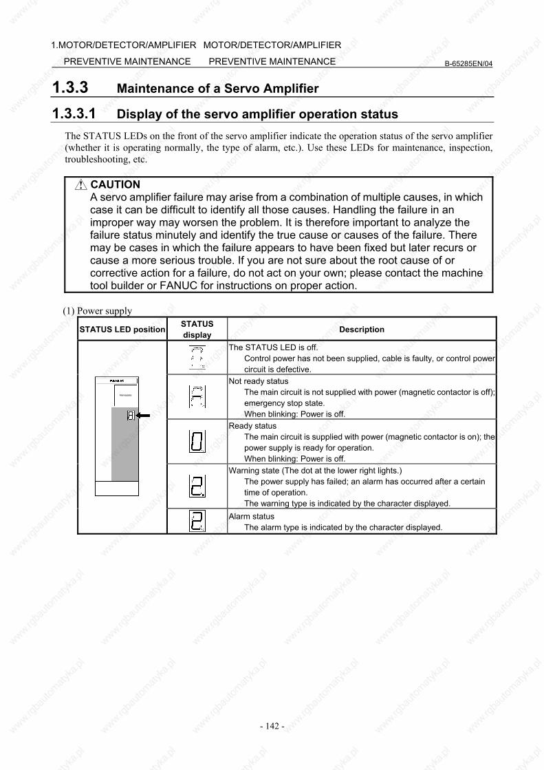
B-65285EN/04
- 142 -
1.MOTOR/DETECTOR/AMPLIFIER
PREVENTIVE MAINTENANCE
MOTOR/DETECTOR/AMPLIFIER
PREVENTIVE MAINTENANCE
1.3.3 Maintenance of a Servo Amplifier
1.3.3.1 Display of the servo amplifier operation status The STATUS LEDs on the front of the servo amplifier indicate the operation status of the servo amplifier (whether it is operating normally, the type of alarm, etc.). Use these LEDs for maintenance, inspection, troubleshooting, etc.
CAUTION A servo amplifier failure may arise from a combination of multiple causes, in which
case it can be difficult to identify all those causes. Handling the failure in an improper way may worsen the problem. It is therefore important to analyze the failure status minutely and identify the true cause or causes of the failure. There may be cases in which the failure appears to have been fixed but later recurs or cause a more serious trouble. If you are not sure about the root cause of or corrective action for a failure, do not act on your own; please contact the machine tool builder or FANUC for instructions on proper action.
(1) Power supply
STATUS LED position STATUS display Description
The STATUS LED is off. Control power has not been supplied, cable is faulty, or control power
circuit is defective.
Not ready status The main circuit is not supplied with power (magnetic contactor is off);
emergency stop state. When blinking: Power is off.
Ready status The main circuit is supplied with power (magnetic contactor is on); the
power supply is ready for operation. When blinking: Power is off.
Warning state (The dot at the lower right lights.) The power supply has failed; an alarm has occurred after a certain
time of operation. The warning type is indicated by the character displayed.
Nameplate
Alarm status The alarm type is indicated by the character displayed.
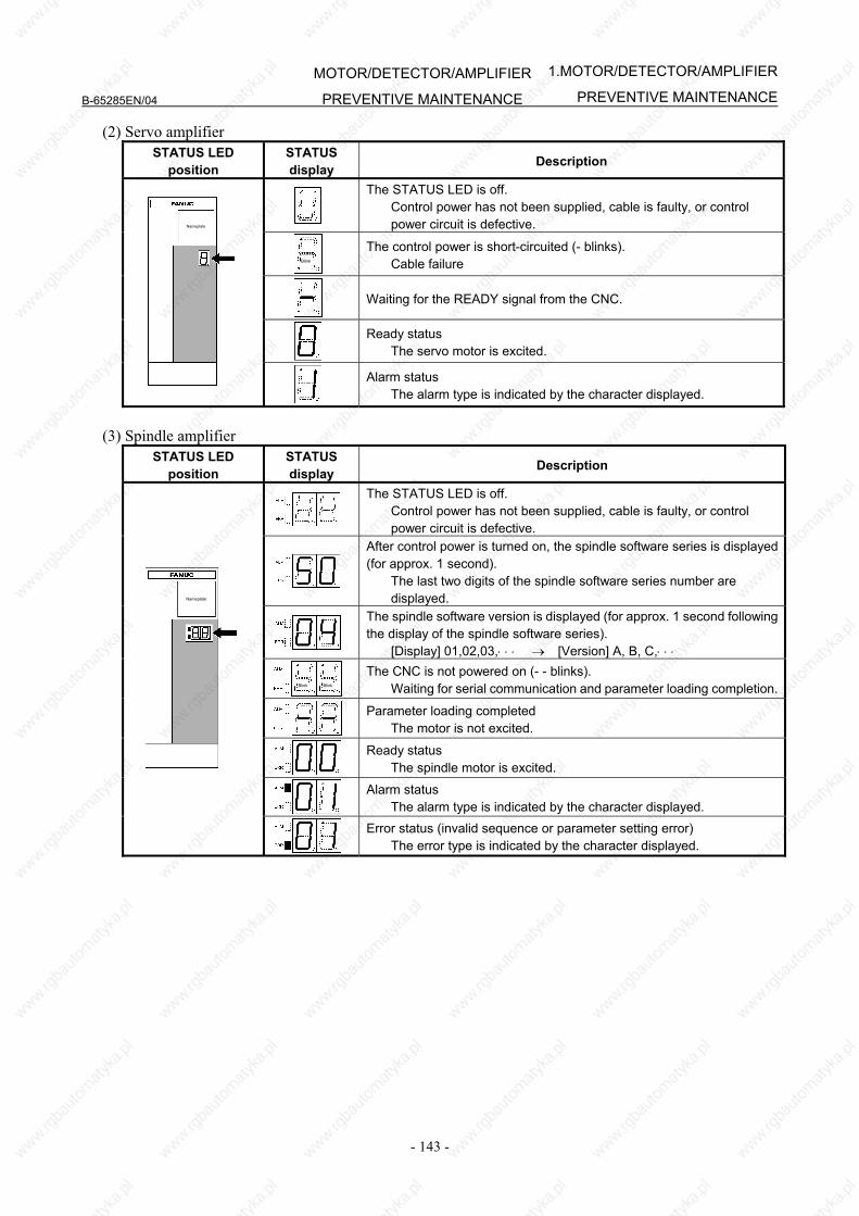
B-65285EN/04
- 143 -
1.MOTOR/DETECTOR/AMPLIFIER
PREVENTIVE MAINTENANCEMOTOR/DETECTOR/AMPLIFIER
PREVENTIVE MAINTENANCE
(2) Servo amplifier STATUS LED
position STATUS display Description
The STATUS LED is off. Control power has not been supplied, cable is faulty, or control
power circuit is defective.
Blink
The control power is short-circuited (- blinks). Cable failure
Waiting for the READY signal from the CNC.
Ready status The servo motor is excited.
Nameplate
Alarm status The alarm type is indicated by the character displayed.
(3) Spindle amplifier
STATUS LED position
STATUS display Description
The STATUS LED is off. Control power has not been supplied, cable is faulty, or control
power circuit is defective.
After control power is turned on, the spindle software series is displayed (for approx. 1 second). The last two digits of the spindle software series number are
displayed.
The spindle software version is displayed (for approx. 1 second following the display of the spindle software series). [Display] 01,02,03,⋅ ⋅ ⋅ → [Version] A, B, C,⋅ ⋅ ⋅
Blink Blink
The CNC is not powered on (- - blinks). Waiting for serial communication and parameter loading completion.
Parameter loading completed The motor is not excited.
Ready status The spindle motor is excited.
Alarm status The alarm type is indicated by the character displayed.
Nameplate
Error status (invalid sequence or parameter setting error) The error type is indicated by the character displayed.
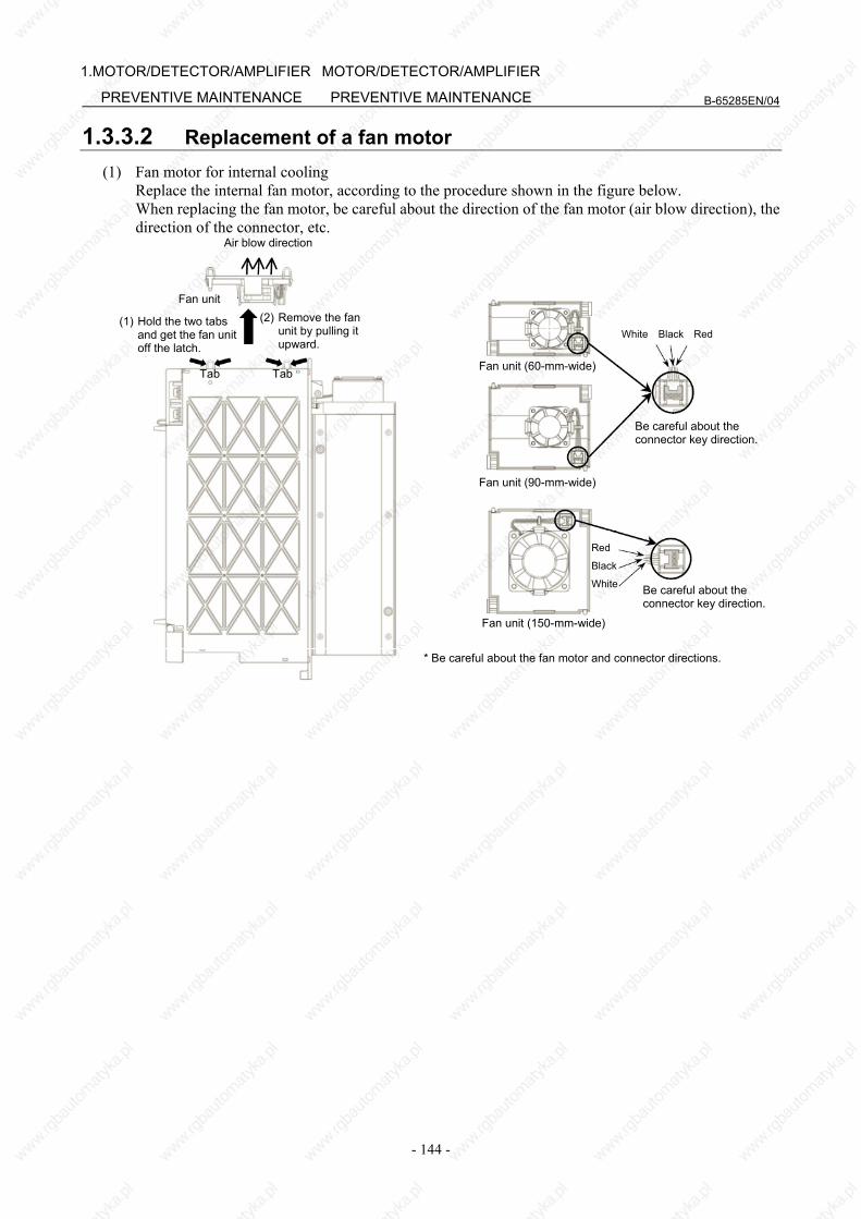
B-65285EN/04
- 144 -
1.MOTOR/DETECTOR/AMPLIFIER
PREVENTIVE MAINTENANCE
MOTOR/DETECTOR/AMPLIFIER
PREVENTIVE MAINTENANCE
1.3.3.2 Replacement of a fan motor (1) Fan motor for internal cooling Replace the internal fan motor, according to the procedure shown in the figure below. When replacing the fan motor, be careful about the direction of the fan motor (air blow direction), the
direction of the connector, etc. Air blow direction
Fan unit
(1) Hold the two tabs and get the fan unitoff the latch.
Tab Fan unit (60-mm-wide)
White Black Red
Be careful about the connector key direction.
(2) Remove the fan unit by pulling it upward.
Tab
Fan unit (90-mm-wide)
Fan unit (150-mm-wide)
Be careful about the connector key direction.
Red
Black
White
* Be careful about the fan motor and connector directions.

B-65285EN/04
- 145 -
1.MOTOR/DETECTOR/AMPLIFIER
PREVENTIVE MAINTENANCEMOTOR/DETECTOR/AMPLIFIER
PREVENTIVE MAINTENANCE
(2) Fan motor for cooling the external radiator <1> Remove the two sheet metal mounting screws (for the 60-mm-wide model only), and detach the
fan motor from the unit together with the sheet metal. <2> Remove the fan motor mounting screws (two for one fan motor and four for two fan motors). <3> Remove the connector mounting screws (two and four for the 300-mm-wide model).
When replacing the fan motor, be careful about the direction of the fan motor (air blow direction), the direction of the connector, etc.
Air blow direction
60 mm wide/90 mm wide
Sheet metal mounting screws
Connector mounting screw Fan motor mounting screw
Air blow direction
150 mm wide
Connector mounting screw Fan motor mounting screw
Air blow direction
300 mm wide
Connector mounting screw Fan motor mounting screw
1.4 REPLACING BATTERY FOR ABSOLUTE PULSECODERS
1.4.1 Overview • When the voltage of the batteries for absolute Pulsecoders becomes low, alarm 307 or 306 occurs, with
the following indication in the CNC state display at the bottom of the CNC screen. Alarm 307 (alarm indicating the voltage of the battery becomes low) : The indication "APC" blinks in reversed display. Alarm 306 (battery zero alarm) : The indication "ALM" blinks in reversed display.
• When alarm 307 (alarm indicating the voltage of the battery becomes low) occurs, replace the battery as soon as possible. In general, the battery should be replaced within one or two weeks, however, this depends on the number of Pulsecoders used.
• When alarm 306 (battery zero alarm) occurs, Pulsecoders are reset to the initial state, in which absolute positions are not held. Alarm 300 (reference position return request alarm) also occurs, indicating that reference position return is required.
• In general, replace the batteries periodically within the service life listed below. - A06B-6050-K061 or D-size alkaline dry cells (LR20) : Two years (for each six-axis
configuration) - A06B-6073-K001 : Two years (for each three-axis configuration) - A06B-6114-K504 : One year (for each three-axis configuration)

B-65285EN/04
- 146 -
1.MOTOR/DETECTOR/AMPLIFIER
PREVENTIVE MAINTENANCE
MOTOR/DETECTOR/AMPLIFIER
PREVENTIVE MAINTENANCE
NOTE
The above values indicate the estimated service life of batteries used with FANUC absolute Pulsecoders. The actual battery service life depends on the machine configuration based on, for example, detector types. For details, contact the machine tool builder.
1.4.2 Replacing Batteries To prevent absolute position information in absolute Pulsecoders from being lost, turn on the machine power before replacing the battery. The replacement procedure is described below. <1> Ensure that the power to the servo amplifier is turned on. <2> Ensure that the machine is in the emergency stop state (the motor is inactive). <3> Ensure that the DC link charge LED of the servo amplifier is off. <4> Detach the old batteries and attach new ones. The replacement of the batteries in a separate battery case and the replacement of the battery built into the servo amplifier are described below in detail.
WARNING
• The absolute Pulsecoder of each of the αi/αiS series servo motors and the βiS series servo motors (βiS0.4 to βiS22) has a built-in backup capacitor. Therefore, even when the power to the servo amplifier is off and the batteries are replaced, reference position return is not required if the replacement completes within less than 10 minutes. Turn the power on and replace the batteries if the replacement will take 10 minutes or more.
• To prevent electric shock, be careful not to touch metal parts in the power magnetics cabinet when replacing the batteries.
• Because the servo amplifier uses a large-capacitance electrolytic capacitor internally, the servo amplifier remains charged for a while even after the power is turned off. Before touching the servo amplifier for maintenance or other purposes, ensure your safety by measuring the residual voltage in the DC link with a tester and confirming that the charge indication LED (red) is off.
• Be sure to replace the batteries with specified ones. Pay attention to the battery polarity. If a wrong type of battery is used or a battery is installed with incorrect polarity, the battery may overheat, blow out, or catch fire, or the absolute position information in the absolute Pulsecoders may be lost.
• Ensure that the battery connector is inserted in the correct position.
1.4.3 Replacing the Batteries in a Separate Battery Case Use the following procedure to replace the batteries in the battery case. <1> Loosen the screws on the battery case and detach the cover. <2> Replace the batteries in the case (pay attention to the polarity). <3> Attach the cover to the battery case.
Battery case (with a cover) A06B-6050-K060
Batteries Four A06B-6050-K061 batteries or D-size alkaline dry cells
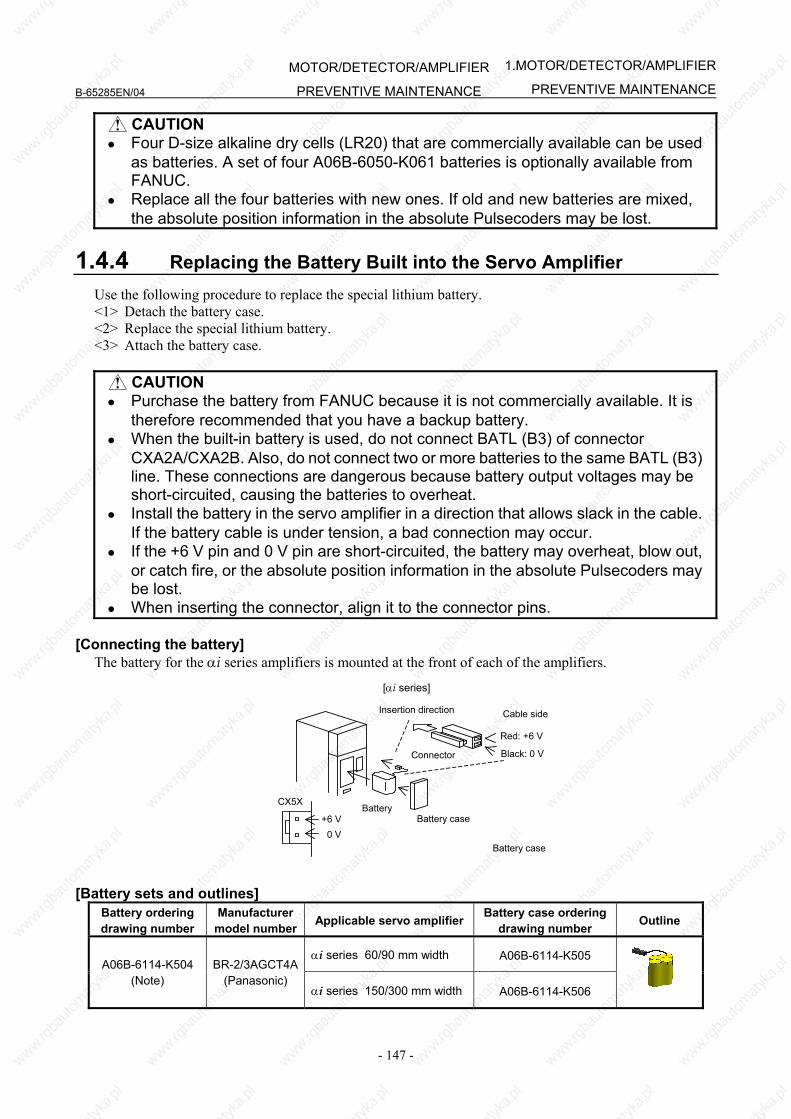
B-65285EN/04
- 147 -
1.MOTOR/DETECTOR/AMPLIFIER
PREVENTIVE MAINTENANCEMOTOR/DETECTOR/AMPLIFIER
PREVENTIVE MAINTENANCE
CAUTION • Four D-size alkaline dry cells (LR20) that are commercially available can be used
as batteries. A set of four A06B-6050-K061 batteries is optionally available from FANUC.
• Replace all the four batteries with new ones. If old and new batteries are mixed, the absolute position information in the absolute Pulsecoders may be lost.
1.4.4 Replacing the Battery Built into the Servo Amplifier Use the following procedure to replace the special lithium battery. <1> Detach the battery case. <2> Replace the special lithium battery. <3> Attach the battery case.
CAUTION • Purchase the battery from FANUC because it is not commercially available. It is
therefore recommended that you have a backup battery. • When the built-in battery is used, do not connect BATL (B3) of connector
CXA2A/CXA2B. Also, do not connect two or more batteries to the same BATL (B3) line. These connections are dangerous because battery output voltages may be short-circuited, causing the batteries to overheat.
• Install the battery in the servo amplifier in a direction that allows slack in the cable. If the battery cable is under tension, a bad connection may occur.
• If the +6 V pin and 0 V pin are short-circuited, the battery may overheat, blow out, or catch fire, or the absolute position information in the absolute Pulsecoders may be lost.
• When inserting the connector, align it to the connector pins. [Connecting the battery]
The battery for the αi series amplifiers is mounted at the front of each of the amplifiers. [αi series]
Battery Battery case
Insertion direction
Red: +6 V
Black: 0 VConnector
Cable side
Battery case
CX5X
+6 V 0 V
[Battery sets and outlines] Battery ordering drawing number
Manufacturer model number Applicable servo amplifier Battery case ordering
drawing number Outline
αi series 60/90 mm width A06B-6114-K505 A06B-6114-K504
(Note) BR-2/3AGCT4A
(Panasonic) αi series 150/300 mm width A06B-6114-K506
B-65285EN/04
- 148 -
1.MOTOR/DETECTOR/AMPLIFIER
PREVENTIVE MAINTENANCE
MOTOR/DETECTOR/AMPLIFIER
PREVENTIVE MAINTENANCE
NOTE When using an old-type battery BR-CCF2TH, order a battery case applicable for
battery A06B-6114-K504.
Used batteries Old batteries should be disposed as "INDUSTRIAL WASTES" according to the regulations of the country or autonomy where your machine has been installed.

IV. MOTOR MAINTENANCE

B-65285EN/04 MOTOR MAINTENANCE
- 151 -
1.SERVO MOTORMAINTENANCE
1 SERVO MOTOR MAINTENANCE
1.1 SERVO MOTOR MAINTENANCE PARTS
1.1.1 Pulsecoder The following lists the ordering specification numbers for maintenance. (1) Pulsecoder: ordering specification
Motor model Motor specification Pulsecoder: ordering specification
X=0 A860-2000-T301 αiA1000 Standard specification
X=1 A860-2005-T301 αiI1000 Standard specification A06B-02aa-BccX
(aa, cc : Any) X=2 A860-2001-T301 αiA16000 Standard specification
X=0 A860-2000-T321 αiA1000 IP67 specification
X=1 A860-2005-T321 αiI1000 IP67 specification
αiS series αiF series
A06B-02aa -BccX #0100 (aa, cc : Any)
X=2 A860-2001-T321 αiA16000 IP67 specification
(2) Oldham's coupling: ordering specification
Motor model Motor specification Oldham's coupling: ordering specification αiS series αiF series
A06B-02aa-BccX (aa, cc, X : Any)
A290-0501-V535
MOTOR MAINTENANCE B-65285EN/04
- 152 -
1.SERVO MOTOR MAINTENANCE
1.1.2 Cooling Fan The following lists the ordering specification numbers of cooling fan units.
αiS 50 with Fan, αiS 60 with Fan, αiF 40 with Fan
Motor model Model name Motor specification Fan unit: ordering specification Remark
αiS 50/3000 with Fan αiS 50/3000HV with Fan
A06B-0275-BXaX A06B-0276-BXaX (X :Any, a=1 or 3)
αiS 60/3000 with Fan αiS 60/3000HV with Fan
A06B-0278-BXaX A06B-0279-BxaX (X :Any, a=1 or 3)
αiS series αiF series
αiF 40/3000 with Fan A06B-0257-BXaX (X :Any, a=1 or 3)
A06B-0241-K053 200VAC1-phase
αiS 100 to αiS 500
Motor model Model name Motor specification Fan unit: ordering specification Remark
αiS 100/2500 with Fan αiS 200/2500 with Fan
αiS 300/2000 αiS 500/2000
A06B-0285-BX1X A06B-0288-BX1X A06B-0292-BX1X A06B-0295-BX1X
(X : Any)
A290-0281-V053 200VAC3-phase
αiS series αiS 100/2500HV with Fan αiS 200/2500HV with Fan
αiS 300/2000HV αiS 300/3000HV αiS 500/2000HV αiS 500/3000HV
A06B-0286-BX1X A06B-0289-BX1X A06B-0293-BX1X A06B-0290-BX1X A06B-0296-BX1X A06B-0297-BX1X
(X : Any)
A290-0281-V054 400VAC3-phase
αiS 1000HV to αS 3000HV
Motor model Model name Motor specification Fan unit: ordering specification Remark
αiS 1000/2000HV A06B-0298-BX1X (X : Any)
A290-0298-V054
αiS 1000/2000HV A06B-0098-BXXX (X : Any)
A290-0098-V051
αiS 1000/3000HV A06B-0099-BXXX (X : Any)
A290-0098-V050 αiS series
αiS 2000/2000HV αiS 3000/2000HV
A06B-0091-BX4X A06B-0092-BX4X
(X : Any) A290-0091-T054
AC400V3-phase
B-65285EN/04 MOTOR MAINTENANCE
- 153 -
1.SERVO MOTORMAINTENANCE
1.2 REPLACING COOLING FANS This section describes how to replace cooling fan units. For each motor, replace the cooling fan unit according to the procedure.
CAUTION Before replacing a fan motor, remove the power lead to the fan motor and check
that the rotation of the fan motor stops. If the load on the fan motor is high or an invalid phase sequence is made for a 3-phase fan motor, the fan motor may overheat and stop. If the power lead is connected, the fan motor suddenly starts rotating when recovered from overheating.
1.2.1 Replacing a Cooling Fan
1.2.1.1 αiS 50 with Fan, αiS 60 with Fan, and αiF 40 with Fan (1) Removing a cooling fan unit
<1> Remove six M6 pan head machine screws fastening the fan cover and remove the front fan cover. You need only to loosen the pan head machine screws indicated by the arrow in the figure.
<2> Remove the cooling fan unit from the motor.
M6 pan head machine screw Fan cover
Cooling fan unit
MOTOR MAINTENANCE B-65285EN/04
- 154 -
1.SERVO MOTOR MAINTENANCE
(2) Mounting a cooling fan unit
<1> Remove six M6 pan head machine screws from a new cooling fan unit and remove the front fan cover.
You need only to loosen the pan head machine screws indicated by the arrow in the figure.
<2> Assemble the cooling fan unit and motor. Align the inside of the sheet metal of the cooling fan unit with the side of the motor and touch the
end of the sheet metal with the back of the motor. (See the figure below.)
Cooling fan unit
Back of motor
M6 pan head machine screw Fan cover
End of sheet metal
Inside of sheet metal
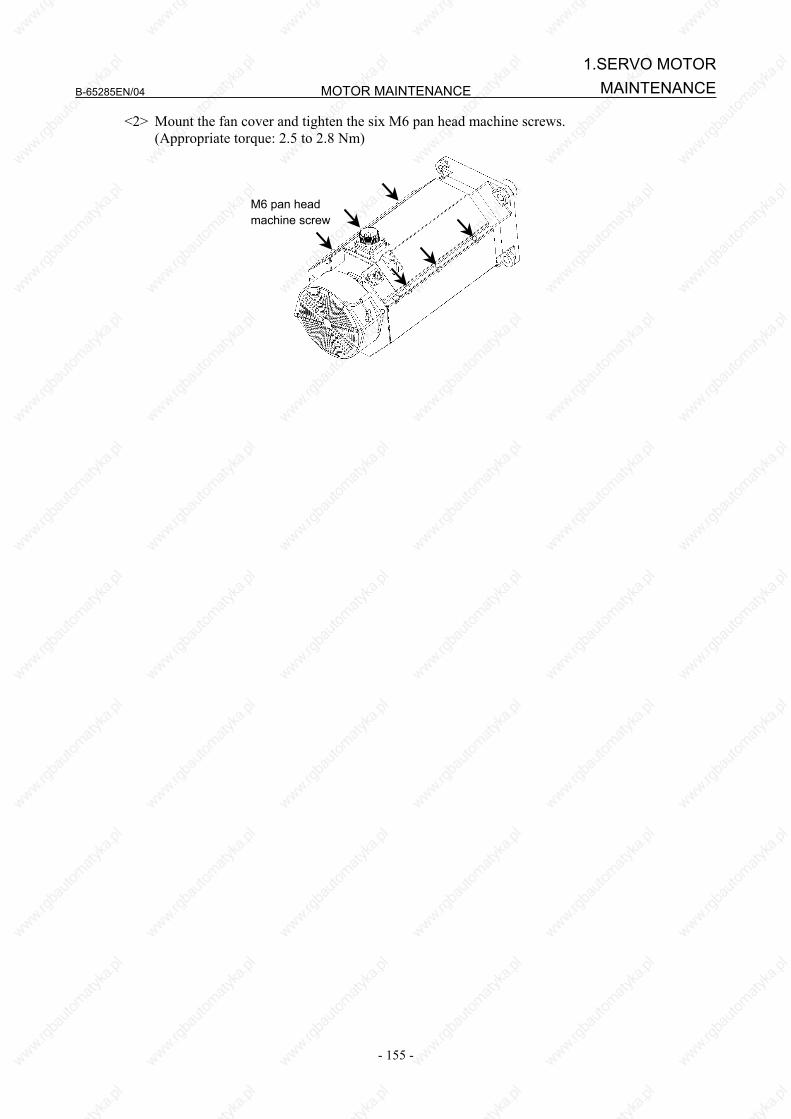
B-65285EN/04 MOTOR MAINTENANCE
- 155 -
1.SERVO MOTORMAINTENANCE
<2> Mount the fan cover and tighten the six M6 pan head machine screws. (Appropriate torque: 2.5 to 2.8 Nm)
M6 pan head machine screw
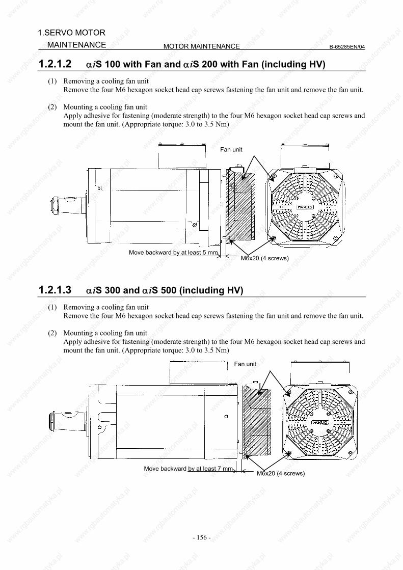
MOTOR MAINTENANCE B-65285EN/04
- 156 -
1.SERVO MOTOR MAINTENANCE
1.2.1.2 αiS 100 with Fan and αiS 200 with Fan (including HV) (1) Removing a cooling fan unit Remove the four M6 hexagon socket head cap screws fastening the fan unit and remove the fan unit. (2) Mounting a cooling fan unit Apply adhesive for fastening (moderate strength) to the four M6 hexagon socket head cap screws and
mount the fan unit. (Appropriate torque: 3.0 to 3.5 Nm)
1.2.1.3 αiS 300 and αiS 500 (including HV) (1) Removing a cooling fan unit Remove the four M6 hexagon socket head cap screws fastening the fan unit and remove the fan unit. (2) Mounting a cooling fan unit Apply adhesive for fastening (moderate strength) to the four M6 hexagon socket head cap screws and
mount the fan unit. (Appropriate torque: 3.0 to 3.5 Nm)
M6x20 (4 screws)
Fan unit
Move backward by at least 5 mm.
M6x20 (4 screws)
Fan unit
Move backward by at least 7 mm
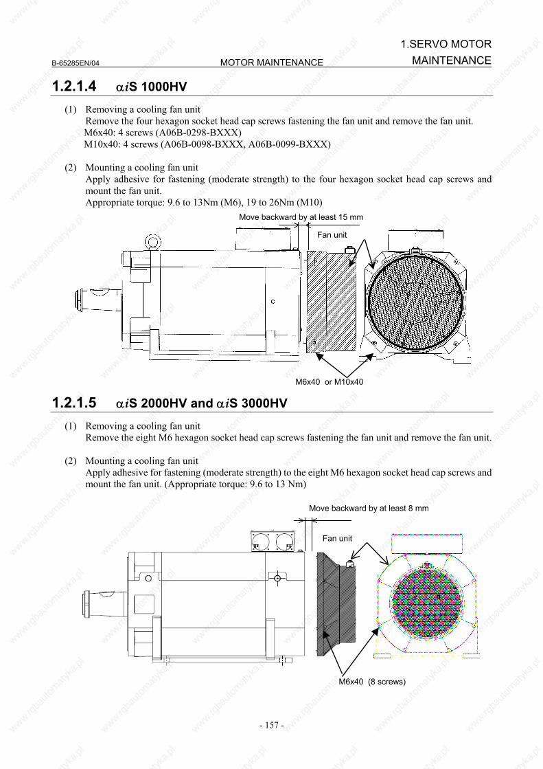
B-65285EN/04 MOTOR MAINTENANCE
- 157 -
1.SERVO MOTORMAINTENANCE
1.2.1.4 αiS 1000HV (1) Removing a cooling fan unit Remove the four hexagon socket head cap screws fastening the fan unit and remove the fan unit.
M6x40: 4 screws (A06B-0298-BXXX) M10x40: 4 screws (A06B-0098-BXXX, A06B-0099-BXXX)
(2) Mounting a cooling fan unit Apply adhesive for fastening (moderate strength) to the four hexagon socket head cap screws and
mount the fan unit. Appropriate torque: 9.6 to 13Nm (M6), 19 to 26Nm (M10)
1.2.1.5 αiS 2000HV and αiS 3000HV (1) Removing a cooling fan unit Remove the eight M6 hexagon socket head cap screws fastening the fan unit and remove the fan unit. (2) Mounting a cooling fan unit Apply adhesive for fastening (moderate strength) to the eight M6 hexagon socket head cap screws and
mount the fan unit. (Appropriate torque: 9.6 to 13 Nm)
M6x40 or M10x40
Fan unit
Move backward by at least 15 mm
M6x40 (8 screws)
Fan unit
Move backward by at least 8 mm
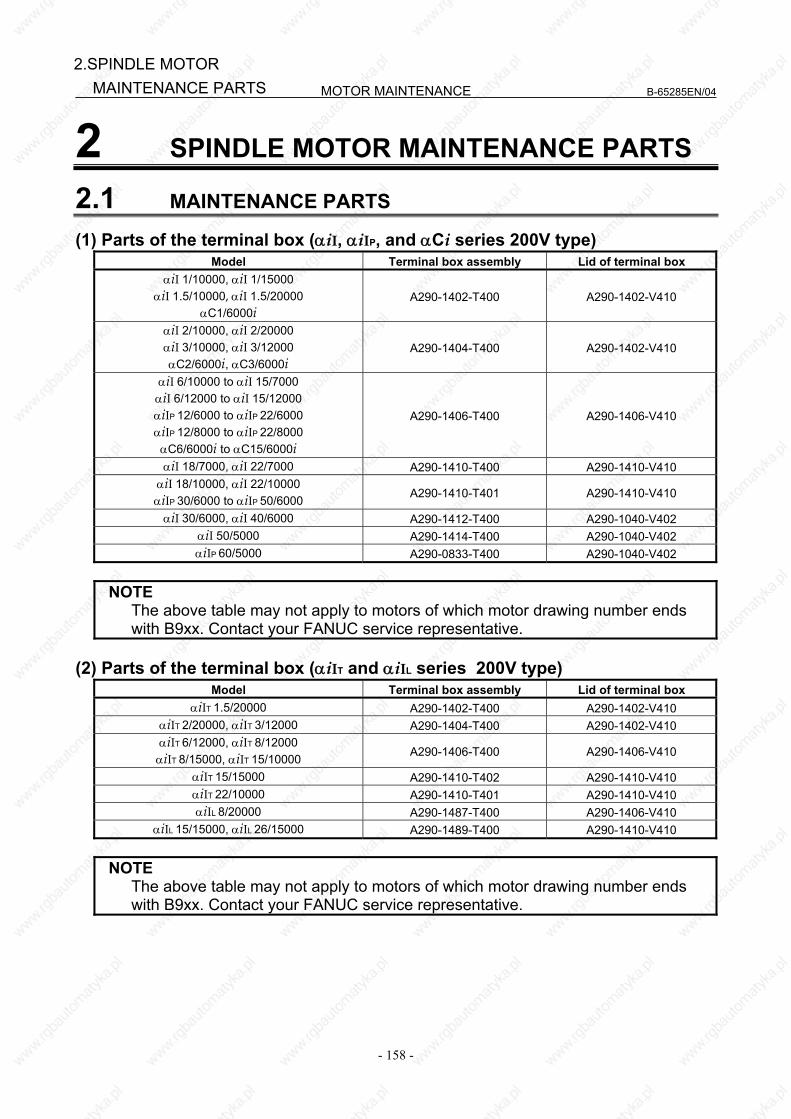
MOTOR MAINTENANCE B-65285EN/04
- 158 -
2.SPINDLE MOTOR MAINTENANCE PARTS
2 SPINDLE MOTOR MAINTENANCE PARTS
2.1 MAINTENANCE PARTS
(1) Parts of the terminal box (αiI, αiIP, and αCi series 200V type) Model Terminal box assembly Lid of terminal box
αiI 1/10000, αiI 1/15000 αiI 1.5/10000, αiI 1.5/20000
αC1/6000i A290-1402-T400 A290-1402-V410
αiI 2/10000, αiI 2/20000 αiI 3/10000, αiI 3/12000 αC2/6000i, αC3/6000i
A290-1404-T400 A290-1402-V410
αiI 6/10000 to αiI 15/7000 αiI 6/12000 to αiI 15/12000 αiIP 12/6000 to αiIP 22/6000 αiIP 12/8000 to αiIP 22/8000 αC6/6000i to αC15/6000i
A290-1406-T400 A290-1406-V410
αiI 18/7000, αiI 22/7000 A290-1410-T400 A290-1410-V410 αiI 18/10000, αiI 22/10000 αiIP 30/6000 to αiIP 50/6000 A290-1410-T401 A290-1410-V410
αiI 30/6000, αiI 40/6000 A290-1412-T400 A290-1040-V402 αiI 50/5000 A290-1414-T400 A290-1040-V402 αiIP 60/5000 A290-0833-T400 A290-1040-V402
NOTE The above table may not apply to motors of which motor drawing number ends
with B9xx. Contact your FANUC service representative.
(2) Parts of the terminal box (αiIT and αiIL series 200V type) Model Terminal box assembly Lid of terminal box
αiIT 1.5/20000 A290-1402-T400 A290-1402-V410 αiIT 2/20000, αiIT 3/12000 A290-1404-T400 A290-1402-V410 αiIT 6/12000, αiIT 8/12000 αiIT 8/15000, αiIT 15/10000 A290-1406-T400 A290-1406-V410
αiIT 15/15000 A290-1410-T402 A290-1410-V410 αiIT 22/10000 A290-1410-T401 A290-1410-V410 αiIL 8/20000 A290-1487-T400 A290-1406-V410
αiIL 15/15000, αiIL 26/15000 A290-1489-T400 A290-1410-V410
NOTE The above table may not apply to motors of which motor drawing number ends
with B9xx. Contact your FANUC service representative.
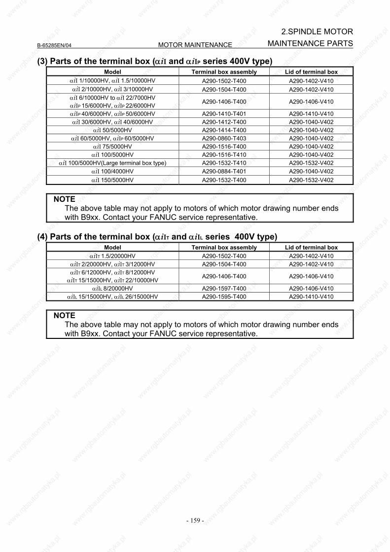
B-65285EN/04 MOTOR MAINTENANCE
- 159 -
2.SPINDLE MOTORMAINTENANCE PARTS
(3) Parts of the terminal box (αiI and αiIP series 400V type) Model Terminal box assembly Lid of terminal box
αiI 1/10000HV, αiI 1.5/10000HV A290-1502-T400 A290-1402-V410 αiI 2/10000HV, αiI 3/10000HV A290-1504-T400 A290-1402-V410 αiI 6/10000HV to αiI 22/7000HV αiIP 15/6000HV, αiIP 22/6000HV
A290-1406-T400 A290-1406-V410
αiIP 40/6000HV, αiIP 50/6000HV A290-1410-T401 A290-1410-V410 αiI 30/6000HV, αiI 40/6000HV A290-1412-T400 A290-1040-V402
αiI 50/5000HV A290-1414-T400 A290-1040-V402 αiI 60/5000HV, αiIP 60/5000HV A290-0860-T403 A290-1040-V402
αiI 75/5000HV A290-1516-T400 A290-1040-V402 αiI 100/5000HV A290-1516-T410 A290-1040-V402
αiI 100/5000HV(Large terminal box type) A290-1532-T410 A290-1532-V402 αiI 100/4000HV A290-0884-T401 A290-1040-V402 αiI 150/5000HV A290-1532-T400 A290-1532-V402
NOTE The above table may not apply to motors of which motor drawing number ends
with B9xx. Contact your FANUC service representative.
(4) Parts of the terminal box (αiIT and αiIL series 400V type) Model Terminal box assembly Lid of terminal box
αiIT 1.5/20000HV A290-1502-T400 A290-1402-V410 αiIT 2/20000HV, αiIT 3/12000HV A290-1504-T400 A290-1402-V410 αiIT 6/12000HV, αiIT 8/12000HV
αiIT 15/15000HV, αiIT 22/10000HV A290-1406-T400 A290-1406-V410
αiIL 8/20000HV A290-1597-T400 A290-1406-V410 αiIL 15/15000HV, αiIL 26/15000HV A290-1595-T400 A290-1410-V410
NOTE The above table may not apply to motors of which motor drawing number ends
with B9xx. Contact your FANUC service representative.
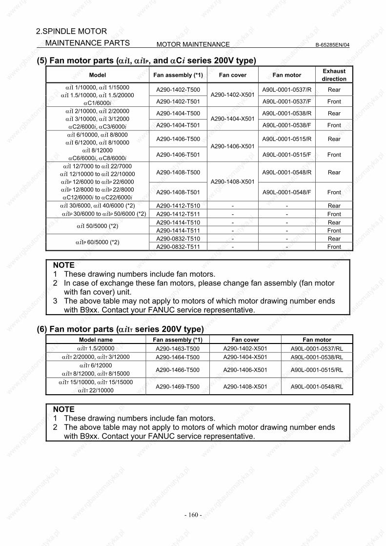
MOTOR MAINTENANCE B-65285EN/04
- 160 -
2.SPINDLE MOTOR MAINTENANCE PARTS
(5) Fan motor parts (αiI, αiIP, and αCi series 200V type) Model Fan assembly (*1) Fan cover Fan motor Exhaust
direction
A290-1402-T500 A90L-0001-0537/R Rear αiI 1/10000, αiI 1/15000 αiI 1.5/10000, αiI 1.5/20000
αC1/6000i A290-1402-T501 A290-1402-X501
A90L-0001-0537/F Front
A290-1404-T500 A90L-0001-0538/R Rear αiI 2/10000, αiI 2/20000 αiI 3/10000, αiI 3/12000 αC2/6000i, αC3/6000i A290-1404-T501
A290-1404-X501A90L-0001-0538/F Front
A290-1406-T500 A90L-0001-0515/R Rear αiI 6/10000, αiI 8/8000 αiI 6/12000, αiI 8/10000
αiI 8/12000 αC6/6000i, αC8/6000i A290-1406-T501
A290-1406-X501A90L-0001-0515/F Front
A290-1408-T500 A90L-0001-0548/R Rear αiI 12/7000 to αiI 22/7000
αiI 12/10000 to αiI 22/10000 αiIP 12/6000 to αiIP 22/6000 αiIP 12/8000 to αiIP 22/8000 αC12/6000i to αC22/6000i
A290-1408-T501
A290-1408-X501
A90L-0001-0548/F Front
A290-1412-T510 - - Rear αiI 30/6000, αiI 40/6000 (*2) αiIP 30/6000 to αiIP 50/6000 (*2) A290-1412-T511 - - Front
A290-1414-T510 - - Rear αiI 50/5000 (*2) A290-1414-T511 - - Front A290-0832-T510 - - Rear αiIP 60/5000 (*2) A290-0832-T511 - - Front
NOTE 1 These drawing numbers include fan motors. 2 In case of exchange these fan motors, please change fan assembly (fan motor
with fan cover) unit. 3 The above table may not apply to motors of which motor drawing number ends
with B9xx. Contact your FANUC service representative.
(6) Fan motor parts (αiIT series 200V type) Model name Fan assembly (*1) Fan cover Fan motor αiIT 1.5/20000 A290-1463-T500 A290-1402-X501 A90L-0001-0537/RL
αiIT 2/20000, αiIT 3/12000 A290-1464-T500 A290-1404-X501 A90L-0001-0538/RL αiIT 6/12000
αiIT 8/12000, αiIT 8/15000 A290-1466-T500 A290-1406-X501 A90L-0001-0515/RL
αiIT 15/10000, αiIT 15/15000 αiIT 22/10000 A290-1469-T500 A290-1408-X501 A90L-0001-0548/RL
NOTE 1 These drawing numbers include fan motors. 2 The above table may not apply to motors of which motor drawing number ends
with B9xx. Contact your FANUC service representative.

B-65285EN/04 MOTOR MAINTENANCE
- 161 -
2.SPINDLE MOTORMAINTENANCE PARTS
(7) Fan motor parts (αiI and αiIP series 400V type) Model Fan assembly (*1) Fan cover Fan motor Exhaust
directionA290-1502-T500 A90L-0001-0539/R Rear αiI 1/10000HV, αiI 1.5/10000HV A290-1502-T501
A290-1402-X501A90L-0001-0539/F Front
A290-1504-T500 A90L-0001-0540/R Rear αiI 2/10000HV, αiI 3/10000HV A290-1504-T501
A290-1404-X501A90L-0001-0540/F Front
A290-1506-T500 A90L-0001-0519/R Rear αiI 6/10000HV, αiI 8/8000HV A290-1506-T501
A290-1406-X501A90L-0001-0519/F Front
A290-1508-T500 A90L-0001-0549/R Rear αiI 12/7000HV, αiI 15/7000HV αiI 22/7000HV
αiIP 15/6000HV, αiIP 22/6000HV A290-1508-T501 A290-1408-X501
A90L-0001-0549/F Front
A290-1512-T510 - - Rear αiI 30/6000HV, αiI 40/6000HV (*2) αiIP 40/6000HV, αiIP 50/6000HV(*2) A290-1512-T511 - - Front
A290-0883-T510 - - Rear αiI 60/5000HV (*2) αiIP 60/5000HV (*2) A290-0883-T511 - - Front
A290-1514-T510 - - Rear αiI 50/5000HV (*2) A290-1514-T511 - - Front
αiI 75/5000HV, αiI 100/5000HV (*2) A290-1516-T500 - - Rear A290-0780-T512 - - A290-0780-T514 - -
Pedestal-sideintake
A290-0780-T513 - - A290-0780-T515 - -
Pedestal-sideexhaust
αiI 100/4000HV (*2)
A290-0884-T500 - - Rear αiI 150/5000HV (*2) A290-1532-T500 - - Rear
NOTE 1 These drawing numbers include fan motors. 2 In case of exchange these fan motors, please change fan assembly (fan motor
with fan cover) unit. 3 The above table may not apply to motors of which motor drawing number ends
with B9xx. Contact your FANUC service representative.
(8) Fan motor parts (αiIT series 400V type) Model name Fan assembly (*1) Fan cover Fan motor
αiIT 1.5/20000HV A290-1563-T500 A290-1402-X501 A90L-0001-0539/RL αiIT 2/20000HV, αiIT 3/12000HV A290-1564-T500 A290-1404-X501 A90L-0001-0540/RL αiIT 6/12000HV, αiIT 8/15000HV A290-1566-T500 A290-1406-X501 A90L-0001-0519/RL
αiIT 15/15000HV, αiIT 22/10000HV A290-1569-T500 A290-1408-X501 A90L-0001-0549/RL
NOTE 1 These drawing numbers include fan motors. 2 The above table may not apply to motors of which motor drawing number ends
with B9xx. Contact your FANUC service representative.


APPENDIX

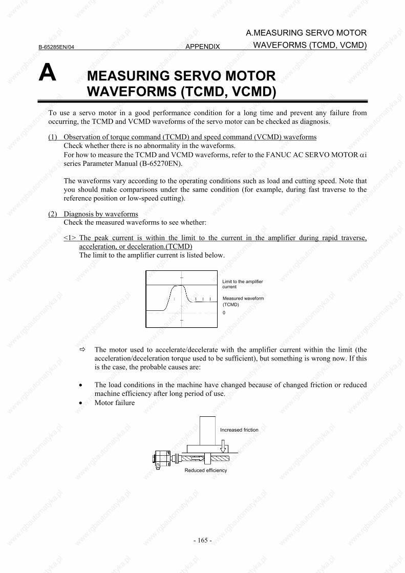
B-65285EN/04 APPENDIX
- 165 -
A.MEASURING SERVO MOTORWAVEFORMS (TCMD, VCMD)
A MEASURING SERVO MOTOR WAVEFORMS (TCMD, VCMD)
To use a servo motor in a good performance condition for a long time and prevent any failure from occurring, the TCMD and VCMD waveforms of the servo motor can be checked as diagnosis. (1) Observation of torque command (TCMD) and speed command (VCMD) waveforms Check whether there is no abnormality in the waveforms. For how to measure the TCMD and VCMD waveforms, refer to the FANUC AC SERVO MOTOR αi
series Parameter Manual (B-65270EN). The waveforms vary according to the operating conditions such as load and cutting speed. Note that
you should make comparisons under the same condition (for example, during fast traverse to the reference position or low-speed cutting).
(2) Diagnosis by waveforms Check the measured waveforms to see whether:
<1> The peak current is within the limit to the current in the amplifier during rapid traverse, acceleration, or deceleration.(TCMD)
The limit to the amplifier current is listed below.
Limit to the amplifier current
Measured waveform (TCMD)
0
The motor used to accelerate/decelerate with the amplifier current within the limit (the
acceleration/deceleration torque used to be sufficient), but something is wrong now. If this is the case, the probable causes are:
• The load conditions in the machine have changed because of changed friction or reduced
machine efficiency after long period of use. • Motor failure
Reduced efficiency
Increased friction
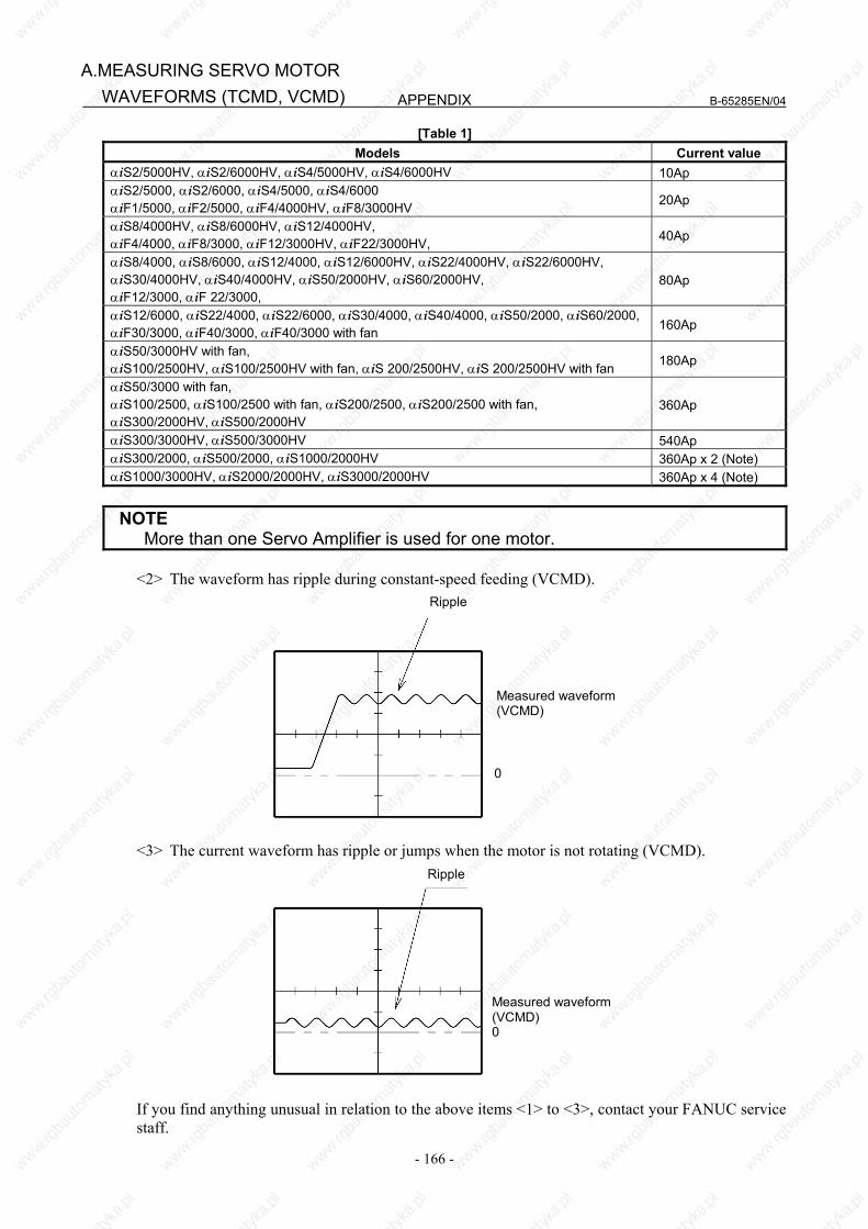
APPENDIX B-65285EN/04
- 166 -
A.MEASURING SERVO MOTOR WAVEFORMS (TCMD, VCMD)
[Table 1] Models Current value
αiS2/5000HV, αiS2/6000HV, αiS4/5000HV, αiS4/6000HV 10Ap αiS2/5000, αiS2/6000, αiS4/5000, αiS4/6000 αiF1/5000, αiF2/5000, αiF4/4000HV, αiF8/3000HV 20Ap
αiS8/4000HV, αiS8/6000HV, αiS12/4000HV, αiF4/4000, αiF8/3000, αiF12/3000HV, αiF22/3000HV, 40Ap
αiS8/4000, αiS8/6000, αiS12/4000, αiS12/6000HV, αiS22/4000HV, αiS22/6000HV, αiS30/4000HV, αiS40/4000HV, αiS50/2000HV, αiS60/2000HV, αiF12/3000, αiF 22/3000,
80Ap
αiS12/6000, αiS22/4000, αiS22/6000, αiS30/4000, αiS40/4000, αiS50/2000, αiS60/2000, αiF30/3000, αiF40/3000, αiF40/3000 with fan 160Ap
αiS50/3000HV with fan, αiS100/2500HV, αiS100/2500HV with fan, αiS 200/2500HV, αiS 200/2500HV with fan 180Ap
αiS50/3000 with fan, αiS100/2500, αiS100/2500 with fan, αiS200/2500, αiS200/2500 with fan, αiS300/2000HV, αiS500/2000HV
360Ap
αiS300/3000HV, αiS500/3000HV 540Ap αiS300/2000, αiS500/2000, αiS1000/2000HV 360Ap x 2 (Note) αiS1000/3000HV, αiS2000/2000HV, αiS3000/2000HV 360Ap x 4 (Note)
NOTE More than one Servo Amplifier is used for one motor.
<2> The waveform has ripple during constant-speed feeding (VCMD).
Ripple
Measured waveform(VCMD)
0
<3> The current waveform has ripple or jumps when the motor is not rotating (VCMD).
Measured waveform(VCMD)0
Ripple
If you find anything unusual in relation to the above items <1> to <3>, contact your FANUC service staff.
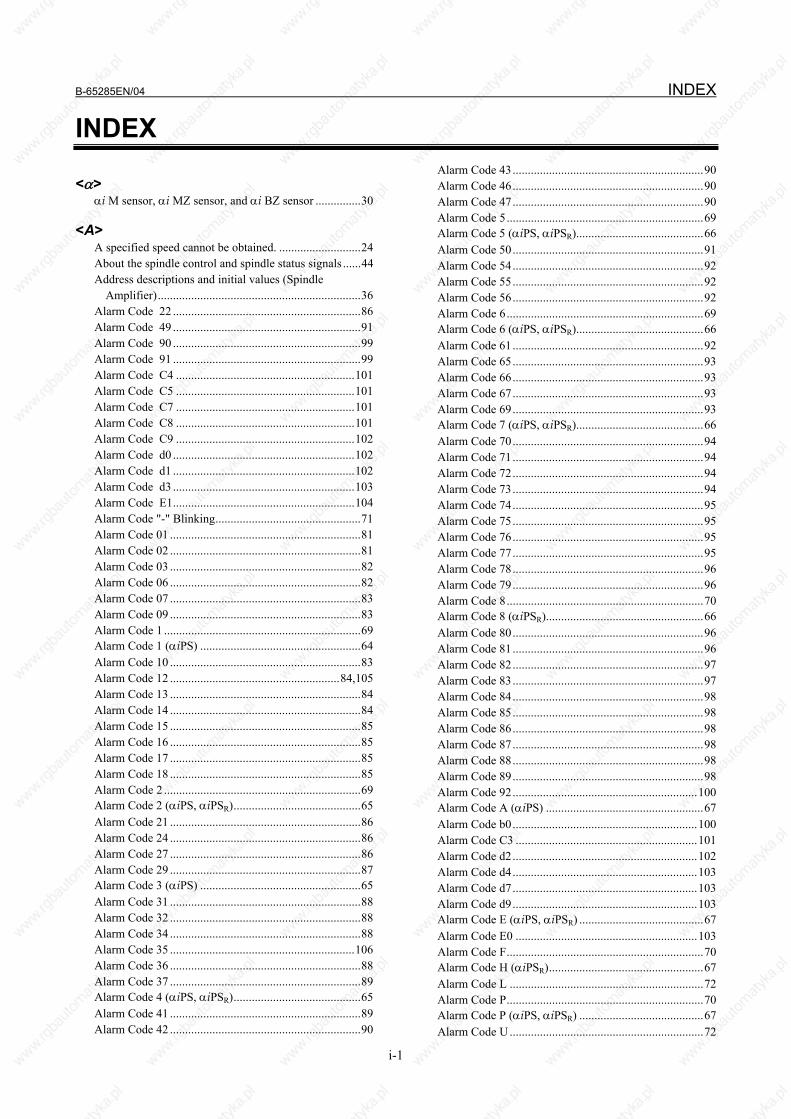
B-65285EN/04 INDEX
i-1
INDEX
<α> αi M sensor, αi MZ sensor, and αi BZ sensor ...............30
<A> A specified speed cannot be obtained. ...........................24 About the spindle control and spindle status signals ......44 Address descriptions and initial values (Spindle
Amplifier)...................................................................36 Alarm Code 22 ..............................................................86 Alarm Code 49 ..............................................................91 Alarm Code 90 ..............................................................99 Alarm Code 91 ..............................................................99 Alarm Code C4 ...........................................................101 Alarm Code C5 ...........................................................101 Alarm Code C7 ...........................................................101 Alarm Code C8 ...........................................................101 Alarm Code C9 ...........................................................102 Alarm Code d0 ............................................................102 Alarm Code d1 ............................................................102 Alarm Code d3 ............................................................103 Alarm Code E1............................................................104 Alarm Code "-" Blinking................................................71 Alarm Code 01 ...............................................................81 Alarm Code 02 ...............................................................81 Alarm Code 03 ...............................................................82 Alarm Code 06 ...............................................................82 Alarm Code 07 ...............................................................83 Alarm Code 09 ...............................................................83 Alarm Code 1 .................................................................69 Alarm Code 1 (αiPS) .....................................................64 Alarm Code 10 ...............................................................83 Alarm Code 12 ........................................................84,105 Alarm Code 13 ...............................................................84 Alarm Code 14 ...............................................................84 Alarm Code 15 ...............................................................85 Alarm Code 16 ...............................................................85 Alarm Code 17 ...............................................................85 Alarm Code 18 ...............................................................85 Alarm Code 2 .................................................................69 Alarm Code 2 (αiPS, αiPSR)..........................................65 Alarm Code 21 ...............................................................86 Alarm Code 24 ...............................................................86 Alarm Code 27 ...............................................................86 Alarm Code 29 ...............................................................87 Alarm Code 3 (αiPS) .....................................................65 Alarm Code 31 ...............................................................88 Alarm Code 32 ...............................................................88 Alarm Code 34 ...............................................................88 Alarm Code 35 .............................................................106 Alarm Code 36 ...............................................................88 Alarm Code 37 ...............................................................89 Alarm Code 4 (αiPS, αiPSR)..........................................65 Alarm Code 41 ...............................................................89 Alarm Code 42 ...............................................................90
Alarm Code 43...............................................................90 Alarm Code 46...............................................................90 Alarm Code 47...............................................................90 Alarm Code 5.................................................................69 Alarm Code 5 (αiPS, αiPSR)..........................................66 Alarm Code 50...............................................................91 Alarm Code 54...............................................................92 Alarm Code 55...............................................................92 Alarm Code 56...............................................................92 Alarm Code 6.................................................................69 Alarm Code 6 (αiPS, αiPSR)..........................................66 Alarm Code 61...............................................................92 Alarm Code 65...............................................................93 Alarm Code 66...............................................................93 Alarm Code 67...............................................................93 Alarm Code 69...............................................................93 Alarm Code 7 (αiPS, αiPSR)..........................................66 Alarm Code 70...............................................................94 Alarm Code 71...............................................................94 Alarm Code 72...............................................................94 Alarm Code 73...............................................................94 Alarm Code 74...............................................................95 Alarm Code 75...............................................................95 Alarm Code 76...............................................................95 Alarm Code 77...............................................................95 Alarm Code 78...............................................................96 Alarm Code 79...............................................................96 Alarm Code 8.................................................................70 Alarm Code 8 (αiPSR)....................................................66 Alarm Code 80...............................................................96 Alarm Code 81...............................................................96 Alarm Code 82...............................................................97 Alarm Code 83...............................................................97 Alarm Code 84...............................................................98 Alarm Code 85...............................................................98 Alarm Code 86...............................................................98 Alarm Code 87...............................................................98 Alarm Code 88...............................................................98 Alarm Code 89...............................................................98 Alarm Code 92.............................................................100 Alarm Code A (αiPS) ....................................................67 Alarm Code b0.............................................................100 Alarm Code C3 ............................................................101 Alarm Code d2.............................................................102 Alarm Code d4.............................................................103 Alarm Code d7.............................................................103 Alarm Code d9.............................................................103 Alarm Code E (αiPS, αiPSR) .........................................67 Alarm Code E0 ............................................................103 Alarm Code F.................................................................70 Alarm Code H (αiPSR)...................................................67 Alarm Code L ................................................................72 Alarm Code P.................................................................70 Alarm Code P (αiPS, αiPSR) .........................................67 Alarm Code U ................................................................72
INDEX B-65285EN/04
i-2
Alarm Codes 19 and 20..................................................85 Alarm Codes 52 and 53..................................................92 Alarm Codes 8., 9., and A. ........................................70,71 Alarm Codes A, A1, and A2 ........................................100 Alarm Codes b, c, and d .................................................71 Alarm Codes C0,C1, and C2........................................101 ALARM NUMBERS AND BRIEF DESCRIPTIONS...50 Alarms for built-in detectors (αi and βi Pulsecoders) and
troubleshooting actions.............................................134 Alarms for separate detectors and troubleshooting
actions ......................................................................135 Alarms Related to Pulsecoder and Separate Serial
Detector ......................................................................78 An overshoot or hunting occurs. ....................................25 Analog αi CZ sensor ......................................................31 Appearance inspection of the linear motor (magnet
plate).........................................................................133
<B> Battery connection modes ............................................115
<C> Caution.................................................... s-5,s-9,s-11,s-13 Check board connection .................................................33 Check Terminal on the Printed-circuit Board ................14 Check terminal output signals ........................................33 Checking Method when Magnetic Contactor Is not
Switched On ...............................................................16 Checking parameters ......................................................42 Checking Parameters Using the Spindle Check Board...42 Checking the Feedback Signal Waveform .....................29 Checking the Phase Sequence of the Fan Motor Power
Supply ........................................................................12 Checking the STATUS Display (Servo Amplifier)........18 Checking the Status LEDs (Power Supply)....................14 Checking the Voltage and Capacity of the Power..........11 αCi SERIES SPINDLE AMPLIFIER MODULE ........105 CONFIGURATIONS.......................................................4 CONFIRMATION OF THE OPERATION ...................13 Connecting a Protective Ground ....................................12 Connecting the battery for the α series motor ..............115 CONNECTING THE POWER ......................................11 Cooling Fan..................................................................152 Cutting power weakens or acceleration/deceleration
slows down. ................................................................25
<D> Data numbers .................................................................39 DB Relay Error (CNC Message "Alarm SV0654")........73 DEFINITION OF WARNING, CAUTION, AND
NOTE ........................................................................s-2 Detailed troubleshooting methods................................135 Diagnosis Screen............................................................74 Display of the servo amplifier operation status ............142
<E> Example of observing data........................................41,45
<F> FANUC AC SERVO MOTOR αis/αi series ................ s-3 FANUC AC SPINDLE MOTOR αi series ................... s-3 FANUC SERVO AMPLIFIER αi series....................... s-8 Feedback Disconnected Alarm.......................................76 FOR Series 0i-D.............................................................61 FOR Series 15i ...............................................................50 FOR Series 16i, 18i, 20i, 21i, 0i, AND Power Mate i ....54 FOR Series 30i/ 31i/32i..................................................58 Fuse Locations .............................................................119
<H> HOW TO REPLACE THE FUSES..............................118
<I> INITIALIZING PARAMETERS...................................12 Invalid Servo Parameter Setting Alarm..........................77 αiS 100 with Fan and αiS 200 with Fan (including HV)
..................................................................................156 αiS 1000HV.................................................................157 αiS 2000HV and αiS 3000HV.....................................157 αiS 300 and αiS 500 (including HV)...........................156 αiS 50 with Fan, αiS 60 with Fan, and αiF 40 with
Fan............................................................................153
<L> LIST OF MANUALS RELATED TO MOTORS AND
AMPLIFIERS...........................................................124 List of spindle data that can be observed using the
SERVO GUIDE .........................................................43
<M> Main inspection items ..................................................127 Maintenance of βiS motor Pulsecoders........................137 Maintenance of a Detector ...........................................134 Maintenance of a Servo Amplifier ...............................142 Maintenance of the FANUC-NSK spindle unit............132 MAINTENANCE PARTS ...........................................158 Major characteristics ......................................................35 MAJOR COMPONENTS ................................................5 MEASURING SERVO MOTOR WAVEFORMS
(TCMD, VCMD)......................................................165 Method for Observing Motor Current ............................19 MOTOR/DETECTOR/AMPLIFIER PREVENTIVE
MAINTENANCE.....................................................124
<N> No LED Display (αiPS, αiPSR) .....................................64 Note............................................................... s-6,s-10,s-13 Notes on attaching connectors .....................................116 Notes on motor cleaning ..............................................130 Notes on Replacing a Battery (Supplementary
Explanation) .............................................................115 Notes on the cutting fluid (informational)....................130
<O> Observation method .......................................................35 Observing Data Using the SERVO GUIDE...................42 Observing Data Using the Spindle Check Board ...........35
B-65285EN/04 INDEX
i-3
Other Alarms...........................................................79,104 Overheat Alarm..............................................................77 Overload Alarm (Soft Thermal, OVC)...........................75 OVERVIEW ....................................... 3,35,42,49,112,145
<P> Periodic cleaning of a motor ........................................130 α position coder S ..........................................................32 Power Supply .......................................................5,13,119 POWER SUPPLY (αiPS, αiPSR)...................................64 PREFACE .................................................................... p-1 Preventive Maintenance of a Built-in Spindle Motor and
Spindle Unit..............................................................131 Preventive Maintenance of a Linear Motor..................133 Preventive Maintenance of a Motor (Common to All
Models).....................................................................127 Preventive Maintenance of a Servo Amplifier .............141 PREVENTIVE MAINTENANCE OF MOTORS AND
DETECTORS...........................................................125 PREVENTIVE MAINTENANCE OF SERVO
AMPLIFIERS...........................................................138 Principles in outputting the internal data of the serial
spindle ........................................................................37 Pulsecoder ....................................................................151
<R> REPLACEMENT OF A FAN MOTOR................107,144 Replacing a Cooling Fan..............................................153 REPLACING AMPLIFIER COMPONENTS..............107 Replacing Batteries ...............................................112,146 REPLACING BATTERY FOR ABSOLUTE
PULSECODERS ...............................................112,145 REPLACING COOLING FANS .................................153 Replacing the Batteries in a Separate Battery Case
...........................................................................113,146 Replacing the Battery Built into the Servo Amplifier
...........................................................................113,147 Routine Inspection of a Spindle Motor with a Through
Hole ..........................................................................131 Routine inspection of the FANUC-NSK spindle unit ..132
<S> SAFETY PRECAUTIONS .......................................... S-1 Selecting the Ground Fault Interrupter That Matches the
Leakage Current .........................................................12 Servo Adjustment Screen ...............................................73 Servo Alarm ....................................................50,54,58,61 Servo Amplifier...............................................6,17,68,119 SERVO MOTOR MAINTENANCE ...........................151 SERVO MOTOR MAINTENANCE PARTS ..............151 SERVO SOFTWARE ....................................................73 Specifying data to be monitored.....................................36 Spindle Alarm .................................................51,55,59,62 Spindle Amplifier............................................8,22,81,120 Spindle Check Board......................................................32 Spindle check board specifications ................................32 SPINDLE MOTOR MAINTENANCE PARTS...........158 START-UP PROCEDURE ............................................11
START-UP PROCEDURE (OVERVIEW) ...................11 STATUS Display (Spindle Amplifier)...........................23 Status Error Indication Function ....................................26 Storage method of the FANUC-NSK spindle unit .......133
<T> Test run of the FANUC-NSK spindle unit ...................133 The motor does not turn. ................................................24 The PIL LED (Power ON Indicator) Is Off....................16 The PIL LED (power-on indicator) is off. .....................23 The STATUS display is blinking with "--." ...................23 TROUBLESHOOTING AND ACTION........................64 Troubleshooting at Startup.............................................23
<U> Usable series and editions ..............................................42
<V> VRDY-OFF Alarm Indicated on the CNC Screen .........18
<W> Warning ...................................................s-3,s-8,s-10,s-12 Warnings and Cautions Relating to a Pilot Run.......... s-10 Warnings and Cautions Relating to Maintenance ....... s-12 Warnings and Cautions Relating to Mounting .............. s-8 Warnings, Cautions, and Notes on Operation of Servo
Amplifiers ................................................................138 Warnings, Cautions, and Notes on Preventive
Maintenance of Motors and Detectors......................125 When cutting is not performed, the spindle vibrates,
making noise. .............................................................25

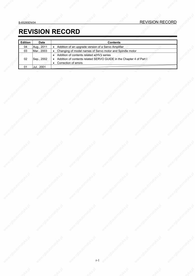
B-65285EN/04 REVISION RECORD
r-1
REVISION RECORD Edition Date Contents
04 Aug., 2011 • Addition of an upgrade version of a Servo Amplifier 03 Mar., 2003 • Changing of model names of Servo motor and Spindle motor
02 Sep., 2002 • Addition of contents related a(HV)i series • Addition of contents related SERVO GUIDE in the Chapter 4 of Part I • Correction of errors
01 Jul., 2001


ADDITIONAL INFORMATION
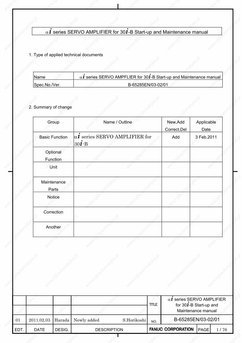
1 / 76
α+ series SERVO AMPLIFIER for 30+-B Start-up and Maintenance manual
EDT. DATE DESIG. DESCRIPTION
B-65285EN/03-02/01 NO.
TITLE
PAGE
α+ series SERVO AMPLIFIER for 30+-B Start-up and Maintenance manual
1. Type of applied technical documents
Name α+ series SERVO AMPFLIER for 30+-B Start-up and Maintenance manual
Spec.No./Ver. B-65285EN/03-02/01
2. Summary of change
Group Name / Outline New,Add
Correct,Del
Applicable
Date
Basic Function
α+ series SERVO AMPLIFIER for 30+-B
Add 3 Feb.2011
Optional
Function
Unit
Maintenance
Parts
Notice
Correction
Another
01 2011.02.03 Harada Newly added S.Horikoshi
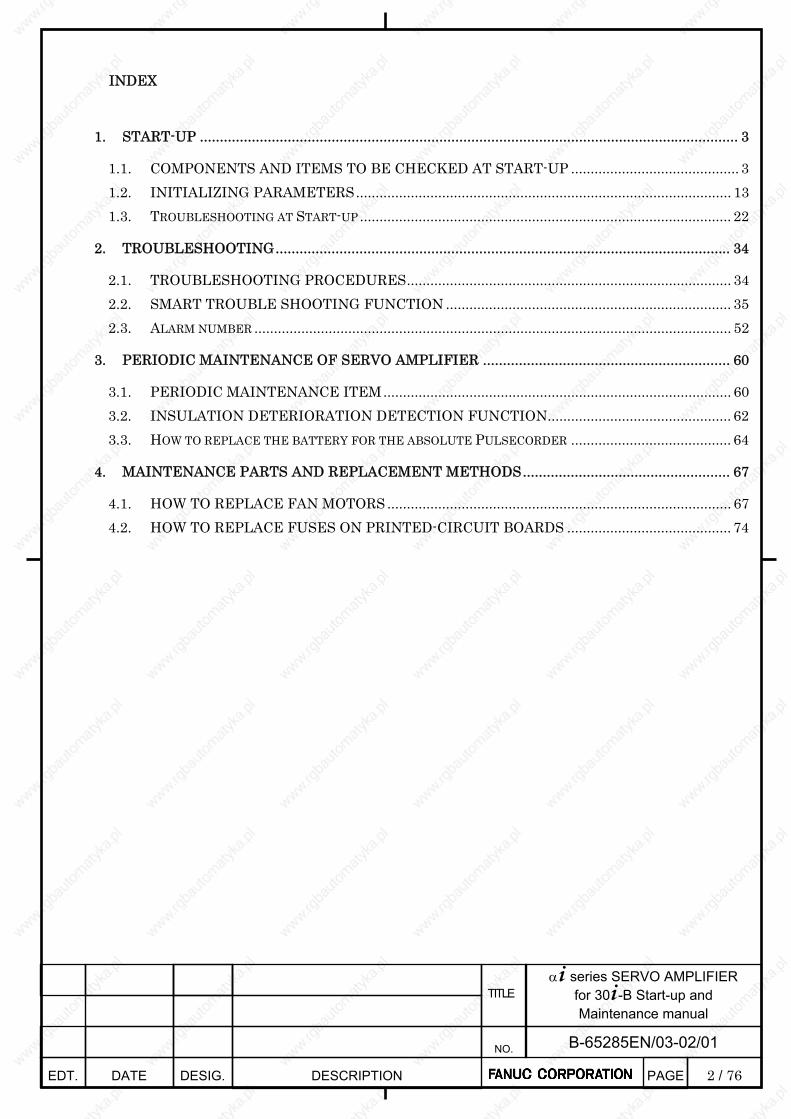
2 / 76
α+ series SERVO AMPLIFIER for 30+-B Start-up and Maintenance manual
EDT. DATE DESIG. DESCRIPTION
B-65285EN/03-02/01 NO.
TITLE
PAGE
INDEX
1. START-UP ....................................................................................................................................... 3
1.1. COMPONENTS AND ITEMS TO BE CHECKED AT START-UP ........................................... 3 1.2. INITIALIZING PARAMETERS................................................................................................ 13 1.3. TROUBLESHOOTING AT START-UP ............................................................................................... 22
2. TROUBLESHOOTING.................................................................................................................. 34
2.1. TROUBLESHOOTING PROCEDURES................................................................................... 34 2.2. SMART TROUBLE SHOOTING FUNCTION ......................................................................... 35 2.3. ALARM NUMBER .......................................................................................................................... 52
3. PERIODIC MAINTENANCE OF SERVO AMPLIFIER .............................................................. 60
3.1. PERIODIC MAINTENANCE ITEM......................................................................................... 60 3.2. INSULATION DETERIORATION DETECTION FUNCTION............................................... 62 3.3. HOW TO REPLACE THE BATTERY FOR THE ABSOLUTE PULSECORDER ......................................... 64
4. MAINTENANCE PARTS AND REPLACEMENT METHODS.................................................... 67
4.1. HOW TO REPLACE FAN MOTORS ........................................................................................ 67 4.2. HOW TO REPLACE FUSES ON PRINTED-CIRCUIT BOARDS .......................................... 74
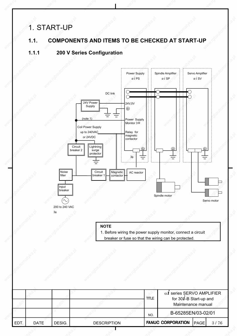
3 / 76
α+ series SERVO AMPLIFIER for 30+-B Start-up and Maintenance manual
EDT. DATE DESIG. DESCRIPTION
B-65285EN/03-02/01 NO.
TITLE
PAGE
1. START-UP
1.1. COMPONENTS AND ITEMS TO BE CHECKED AT START-UP
1.1.1 200 V Series Configuration
Circuit breaker 2
DC link
Lightning surge
protector
Noise filter
Input breaker
AC reactor
200 to 240 VAC
3φ
Servo motor
3φ
Power Supply
αi PS
Spindle Amplifier
αi SP
Servo Amplifier
αi SV
Spindle motor
24V,0V
Magnetic contactor
24V Power Supply
Power SupplyMonitor 3Φ
Circuit breaker 1
(note 1)
Relay for magnetic contactor
Coil Power Supply
up to 240VAC
or 24VDC
NOTE 1. Before wiring the power supply monitor, connect a circuit
breaker or fuse so that the wiring can be protected.
4 / 76
α+ series SERVO AMPLIFIER for 30+-B Start-up and Maintenance manual
EDT. DATE DESIG. DESCRIPTION
B-65285EN/03-02/01 NO.
TITLE
PAGE
1.1.2 400 V Series Configuration
Circuit breaker 2
DC link
Lightning surge
protector
Noise filter
Input breaker
AC reactor
400 to 480 VAC
3φ
Servo motor
3φ
Power Supply
αi PS
Spindle Amplifier
αi SP
Servo Amplifier
αi SV
Spindle motor
24V,0V
Magnetic contactor
24V Power Supply
Power SupplyMonitor 3Φ
Circuit breaker 1
(note 1)
Relay for magnetic contactor
Coil Power Supply
up to 240VAC
or 24VDC
NOTE 1. Before wiring the power supply monitor, connect a circuit
breaker or fuse so that the wiring can be protected.
5 / 76
α+ series SERVO AMPLIFIER for 30+-B Start-up and Maintenance manual
EDT. DATE DESIG. DESCRIPTION
B-65285EN/03-02/01 NO.
TITLE
PAGE
1.1.3 Label and Display on α+ PS
FANUC LABEL
LED display
A06B-6200-H011 A Specification Number
Unit Version
V00000000 Manufacture number
POWER ON LED (GREEN)
ALARM
LED (RED)
NUMBER
POWER ON LED(GREEN):Lighting when control power ON
ALARM LED(RED):Lighting when Alarm status
ERROR LED(ORANGE):Lighting when Error status
ERROR
LED(ORANGE)
・Alarm number ・Warning number ・Software series and version
6 / 76
α+ series SERVO AMPLIFIER for 30+-B Start-up and Maintenance manual
EDT. DATE DESIG. DESCRIPTION
B-65285EN/03-02/01 NO.
TITLE
PAGE
Detail of LED Display of α+ PS
ALARM LED
ERROR LED
STATUSLED
Contents
LED is off Control power has not been supplied. Fault of hardware.
Number / alphabet
The software series/edition is displayed at 4 sessions for about 4 seconds after the power is turned on. First 1 sec: Upper 2 digits of the software series Second 1 sec: Lower 2 digits of the software series Third 1sec : Upper 2 digits of software version Forth 1sec : Lower 2 digits of software version Example) In case of Software serie/version 9G00/01.0
9 G → 0 0 → 0 1 → _ 0
-- Blink
Serial communication with the servo or spindle amplifier is being established
--
Lighting Serial communication with the servo or spindle amplifier is established
00
Blink Start up main power (Precharging)
00 Ready main power
Lighting Number
01~ Alarm status
Number
01~ Warning status
7 / 76
α+ series SERVO AMPLIFIER for 30+-B Start-up and Maintenance manual
EDT. DATE DESIG. DESCRIPTION
B-65285EN/03-02/01 NO.
TITLE
PAGE
1.1.4 Label and Display on α+ SV
FANUC
LABEL
LED display
A06B-6240-H210 A Specification Number
Unit Vertion
V00000000 Manufacture Number
Number
・Alarm number ・Warning number ・Software series and version

8 / 76
α+ series SERVO AMPLIFIER for 30+-B Start-up and Maintenance manual
EDT. DATE DESIG. DESCRIPTION
B-65285EN/03-02/01 NO.
TITLE
PAGE
Detail of LED Display of α+ SV
LED Contents
LED is off Control power has not been supplied. Fault of hardware
Number Lighting
The software series/version is displayed at 4seconds after the power is turned on. Example) In case of software series/version is 9H00/01.0
9 → H → 0 → 0 → 0 → 1 → . → 0 -
Blink Self-Check
- Lighting
SV is waiting for a ready signal
- Blink
Measuring isolation resistor
- Lighting
SV is ready to operate
Number 1~
Alarm state
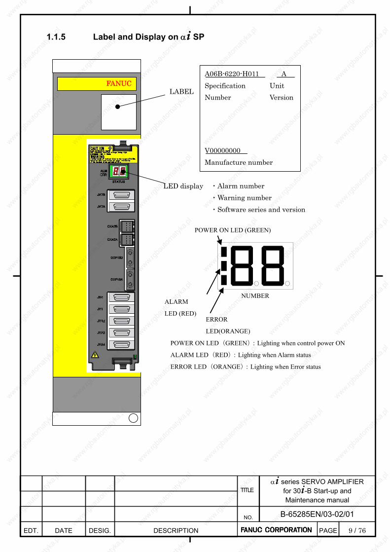
9 / 76
α+ series SERVO AMPLIFIER for 30+-B Start-up and Maintenance manual
EDT. DATE DESIG. DESCRIPTION
B-65285EN/03-02/01 NO.
TITLE
PAGE
1.1.5 Label and Display on α+ SP
FANUCLABEL
LED display
A06B-6220-H011 A Specification Number
Unit Version
V00000000 Manufacture number
POWER ON LED (GREEN)
ALARM
LED (RED)
NUMBER
POWER ON LED(GREEN):Lighting when control power ON
ALARM LED(RED):Lighting when Alarm status
ERROR LED(ORANGE):Lighting when Error status
ERROR
LED(ORANGE)
・Alarm number ・Warning number ・Software series and version
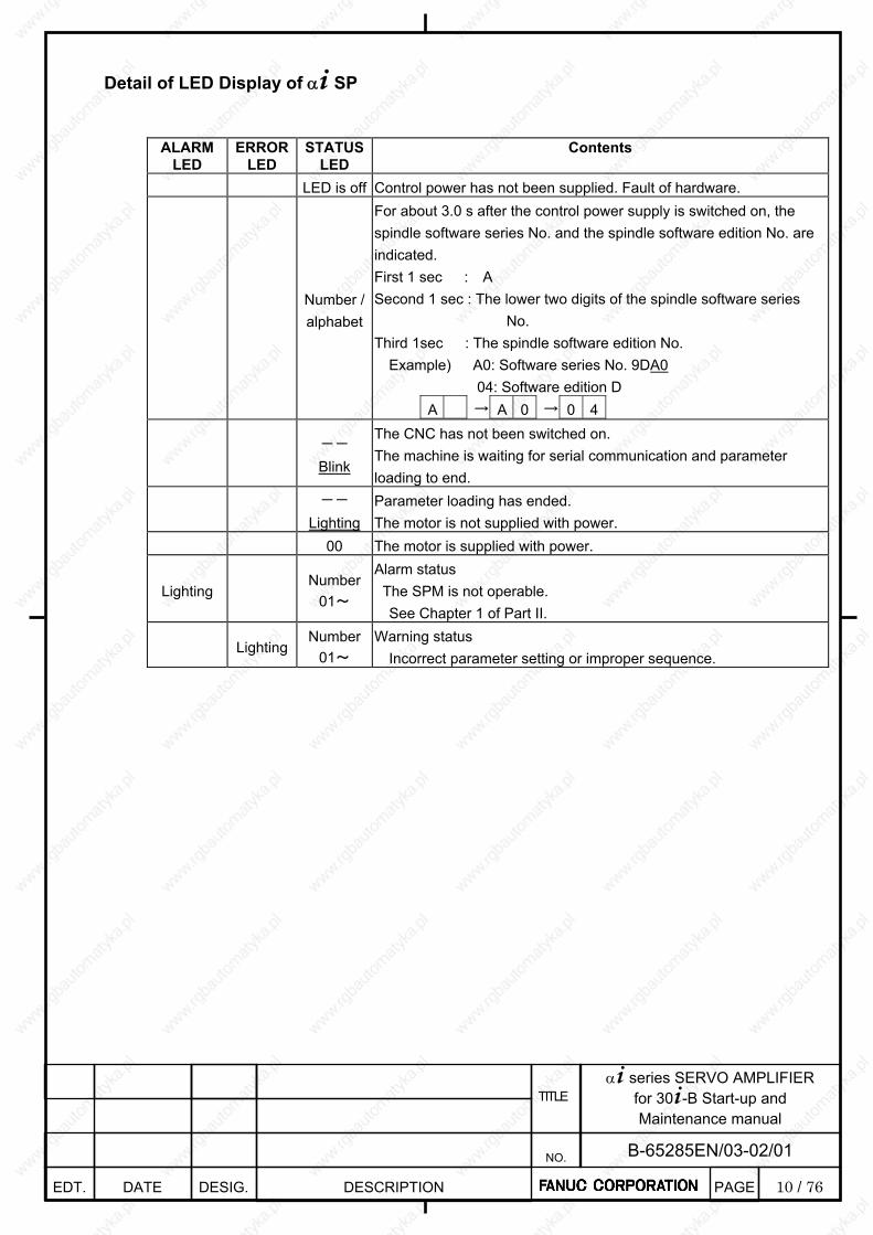
10 / 76
α+ series SERVO AMPLIFIER for 30+-B Start-up and Maintenance manual
EDT. DATE DESIG. DESCRIPTION
B-65285EN/03-02/01 NO.
TITLE
PAGE
Detail of LED Display of α+ SP
ALARM LED
ERROR LED
STATUSLED
Contents
LED is off Control power has not been supplied. Fault of hardware.
Number / alphabet
For about 3.0 s after the control power supply is switched on, the spindle software series No. and the spindle software edition No. are indicated. First 1 sec : A Second 1 sec : The lower two digits of the spindle software series
No. Third 1sec : The spindle software edition No. Example) A0: Software series No. 9DA0
04: Software edition D A → A 0 → 0 4
-- Blink
The CNC has not been switched on. The machine is waiting for serial communication and parameter loading to end.
--
Lighting Parameter loading has ended. The motor is not supplied with power.
00 The motor is supplied with power.
Lighting Number
01~
Alarm status The SPM is not operable. See Chapter 1 of Part II.
Lighting Number
01~ Warning status Incorrect parameter setting or improper sequence.
11 / 76
α+ series SERVO AMPLIFIER for 30+-B Start-up and Maintenance manual
EDT. DATE DESIG. DESCRIPTION
B-65285EN/03-02/01 NO.
TITLE
PAGE
1.1.6 Check Items No. Description Check method Servo amplifier installation status check 1 Servo amplifier and
servo motor specifications
Check the combination of the servo amplifier and servo motor referring to Section 4.1 of “α+ series Servo Amplifier Descriptions” (B-65282EN/06).
2 Flange packing Check the supplied packing is attached properly and that there is no gap between the control panel and amplifier flange.
3 Maintenance area Please keep a maintenance area for the amplifier. For details, refer to Section 5.1 of the document (B-65282EN/06-18) attached to “α+ series Servo Amplifier Descriptions”.
4 Preventing contact with any current-carrying section
Check a protective plate is attached to the DC link terminal board properly and the terminal board cover is locked. For details, refer to Section 5.3 of the document (B-65282EN/06-18) attached to “α+ series Servo Amplifier Descriptions”.
5 Order of amplifier locations
As for the α+SP45HV or the larger model, there is a rule to place the amplifiers. For details, refer to Section 5.3 of the document (B-65282EN/06-18) attached to “α+ series Servo Amplifier Descriptions”.
6 Prevent cutting fluid intrusion
Take a measure to prevent electroconductive, flammable, and corrosive material as well as mist and water drop from getting in the unit. For the detail of an effective closeness of the control panel, refer to Appendix G of “α+ series Servo Amplifier Descriptions” (B-65282EN/06).
Servo amplifier wiring status check 7 Tightening terminal
board screws When connecting wires to the servo amplifier terminal board, be sure to tighten the screws with a proper torque. For the detail of the tightening torque for the terminal board screws, refer to Subsection 5.5.2.9 of “α+ series Servo Amplifier Descriptions” (B-65282EN/06).
8 Connecting a protective ground
Use a proper cable for grounding in order to prevent electrical shocks at a ground fault. For details, refer to Subsection 9.3.1.7 of “α+ series Servo Amplifier Descriptions” (B-65282EN/06).
9 Installing a lightning surge protector
In order to prevent damage due to a surge voltage applied to the input power supply, install a lightning surge protector. For details, refer to Appendix A of “α+ series Servo Amplifier Descriptions” (B-65282EN/06).
10 Measure for noise Check that ground wires, including feedback cable shielding clamps, are connected to proper places to maintain a stable operation of the machine. For details, refer to Section 5.2 of “α+ series Servo Amplifier Descriptions” (B-65282EN/06) and Subsection 7.2.5 of the document (B-65282EN/06-18) attached to “α+ series Servo Amplifier Descriptions”. Also refer to Subsection 7.2.8 if the 24 V power supply is shared between the servo amplifier and the CNC.
(Continued on the next page)
12 / 76
α+ series SERVO AMPLIFIER for 30+-B Start-up and Maintenance manual
EDT. DATE DESIG. DESCRIPTION
B-65285EN/03-02/01 NO.
TITLE
PAGE
(Continued from the previous page) 11 Order of motor power
line phases If the order of motor power line phases is incorrect, there is a risk of an unexpected behavior of motor. So, make sure that the power wires are connected to the motor properly.
12 Checking the axis where motor feedback and power wires are connected
If the axis where motor feedback and power wires are connected is incorrect, there is a risk of an unexpected behavior of motor. So, make sure that the connection is correct.
13 Battery connection Do not connect the built-in batteries in parallel. Please make sure, if the built-in batteries are used with an amp-to-amp battery connection cable (CXA2A/B or BATL (B3)) attached, they may be connected in parallel. For details, refer to Subsection 9.3.2.10 of “α+ series Servo Amplifier Descriptions” (B-65282EN/06).
Operation start-up check 14 Power supply voltage
check Before turning power on, check that the power supply voltage is in its proper range. For details of the power supply voltage specification, refer to Section 2.1 of “α+ series Servo Amplifier Descriptions” (B-65282EN/06).
15 Ground potential check The 400 V servo amplifier supports only neutral grounding. For details, refer to Section 2.1 of “α+ series Servo Amplifier Descriptions” (B-65282EN/06).
16 Ground fault interrupter setting
Use a ground fault interrupter that supports inverters. For explanations about leakage current, refer to Section 5.1 of “α+ series Servo Amplifier Descriptions” (B-65282EN/06).
17 Control power check Check that the voltage of the 24 V power supply for amplifiers is in its proper range and the selected current capacity is proper. For details, refer to Section 4.5 and Subsection 7.2.8 of the document (B-65282EN/06-18) attached to “α+ series Servo Amplifier Descriptions”.
18 Parameter setting Set initial parameters while referencing Section 1.2 of this document. 19 Handling early failures Solve start-up problems, such as being impossible to turn power on, motor
failing to rotate, and alarm occurrence, while referencing Section 1.3 of this document.

13 / 76
α+ series SERVO AMPLIFIER for 30+-B Start-up and Maintenance manual
EDT. DATE DESIG. DESCRIPTION
B-65285EN/03-02/01 NO.
TITLE
PAGE
1.2. INITIALIZING PARAMETERS
1.2.1 Common Power Supply
The common power supply (PS) for the 30+-B series is controlled by software. So, information concerning the power supply can be known on the CNC. Using these informations makes it possible to diagnose failures resulting from power supply fluctuation.
Unlike the servo amplifier (SV) or spindle amplifier (SP), PS cannot communicate directly with CNC. So, the power supply information is transferred through SV or SP to CNC.
1.2.1.1 Amplifier group number
A group of one PS and the servo and spindle amplifiers connected to the PS is defined as an “amplifier group”. This means that a system having more than one PS has more than one amplifier group. A unique number is assigned to each amplifier group. The unique number is described as “amplifier group number”.
1.2.1.2 PS control axis The PS is connected to amplifiers via the CXA2x connector. In this connection, let us refer to an axis driven by
the servo/spindle amplifier nearest to the PS is described as “PS control axis”. The power supply information mentioned above is transferred through this PS control axis to the CNC.
CXA2B
CXA2B
CXA2A
CXA2A
CXA2B
CXA2A
CXA2B
CXA2A
CXA2A
CXA2B
CXA2A
CXA2B
CXA2A
CXA2A
CXA2B
CXA2A
CXA2B
CXA2B
SV or SPPS SV or SP
power supply informationpower supply information
CNC
SV or SP
PS controlaxis
amplifier group "1"
SV or SPPS SV or SP
power supply informationpower supply information
SV or SP
PS controlaxis
amplifier group "2"
SV or SPPS SV or SP
power supply informationpower supply information
SV or SP
PS controlaxis
amplifier group "N"
14 / 76
α+ series SERVO AMPLIFIER for 30+-B Start-up and Maintenance manual
EDT. DATE DESIG. DESCRIPTION
B-65285EN/03-02/01 NO.
TITLE
PAGE
1.2.1.3 Parameter setting for specifying a PS control axis
Using the servo and spindle amplifiers for the 30+-B series requires the following procedure. 1.2.1.3a Parameter setting procedure
In order for the CNC software to recognize the PS control axis, it is necessary to set an amplifier group number in either of the following parameters:
Parameter No. 2557 in case the PS control axis is a servo axis Parameter No. 4657 in case the PS control axis is a spindle axis
This setting can be made automatically with the following procedure.
(1) Set bit 0 (APS) of parameter No. 11549 to 1. The message “PW0000 POWER MUST BE OFF” appears on the alarm message screen. So turn the CNC
power off and on again. Parameters Nos. 2557 and 4657 are automatically set with an amplifier group number, thus completing PS control axis parameter setting.
* Upon completion of automatic parameter setting, bit 0 of parameter No. 11549 returns to 0. * If the amplifier configuration is changed, the alarm “PS CONTROL AXIS ERROR” occurs just after CNC start-up. So, perform automatic parameter setting again.
Related parameter Description
No.11549#0(APS) Setting this parameter to 1 causes an amplifier group number to be
automatically set in PS control axis parameter No. 2557 or 4657.
No.2557 In case the servo axis is a PS control axis, an amplifier group number
is set for the PS control axis.
No.4657 In case the spindle axis is a PS control axis, an amplifier group
number is set for the PS control axis.

15 / 76
α+ series SERVO AMPLIFIER for 30+-B Start-up and Maintenance manual
EDT. DATE DESIG. DESCRIPTION
B-65285EN/03-02/01 NO.
TITLE
PAGE
1.2.1.3b Concrete parameter setting examples
Amplifier Group1 PS SP SV SV SV
S1 X Y Z
Amplifier Group2 PS SV SV SP
A B S2
C
N
C
For the amplifier configuration shown above, the parameters are set as shown below. Amplifier group numbers 1 and 2 are assigned automatically.
Amplifier Group1 PS SP SV SV SV
S1 X Y Z
No.2557 0 0 0
No.4657 1
Amplifier Group2 PS SV SV SP
A B S2
No.2557 2 0
No.4657 0
16 / 76
α+ series SERVO AMPLIFIER for 30+-B Start-up and Maintenance manual
EDT. DATE DESIG. DESCRIPTION
B-65285EN/03-02/01 NO.
TITLE
PAGE
1.2.2 Servo Amplifiers
1.2.2.1 Servo parameter initialization procedure The initialization procedure for servo amplifiers and servo motors is described below. For details of each item of the procedure, refer to “FANUC AC SERVO MOTOR α+ series/FANUC AC SERVO MOTOR β+ series/FANUC LINEAR L+S series/FANUC BUILT-IN SERVO MOTOR D+S series Parameter Manual” (B-65270).
Setting of servo parameter Setting
Initialization bits
Motor No.
AMR
CMR
Flexible feed gear
Move direction
Velocity pulse
Reference counter
Full closed loop
Servo loop gain
Turn power off then on
Absolute position detection setting
Preparation - In emergency stop state, switch on CNC
- Set parameter write enable
- Servo adjusting screen
End of parameter setting
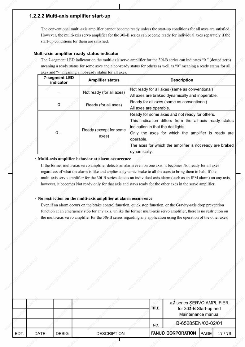
17 / 76
α+ series SERVO AMPLIFIER for 30+-B Start-up and Maintenance manual
EDT. DATE DESIG. DESCRIPTION
B-65285EN/03-02/01 NO.
TITLE
PAGE
1.2.2.2 Multi-axis amplifier start-up The conventional multi-axis amplifier cannot become ready unless the start-up conditions for all axes are satisfied. However, the multi-axis servo amplifier for the 30i-B series can become ready for individual axes separately if the start-up conditions for them are satisfied.
Multi-axis amplifier ready status indicator The 7-segment LED indicator on the multi-axis servo amplifier for the 30i-B series can indicates “0.” (dotted zero) meaning a ready status for some axes and a not-ready status for others as well as “0” meaning a ready status for all axes and “-” meaning a not-ready status for all axes.
7-segment LED indicator Amplifier status Description
- Not ready (for all axes)Not ready for all axes (same as conventional) All axes are braked dynamically and inoperable.
0 Ready (for all axes) Ready for all axes (same as conventional) All axes are operable.
0. Ready (except for some
axes)
Ready for some axes and not ready for others. This indication differs from the all-axis ready status indication in that the dot lights. Only the axes for which the amplifier is ready are operable. The axes for which the amplifier is not ready are braked dynamically.
・Multi-axis amplifier behavior at alarm occurrence If the former multi-axis servo amplifier detects an alarm even on one axis, it becomes Not ready for all axes regardless of what the alarm is like and applies a dynamic brake to all the axes to bring them to halt. If the multi-axis servo amplifier for the 30i-B series detects an individual-axis alarm (such as an IPM alarm) on any axis, however, it becomes Not ready only for that axis and stays ready for the other axes in the servo amplifier.
・No restriction on the multi-axis amplifier at alarm occurrence Even if an alarm occurs on the brake control function, quick stop function, or the Gravity-axis drop prevention function at an emergency stop for any axis, unlike the former multi-axis servo amplifier, there is no restriction on the multi-axis servo amplifier for the 30i-B series regarding any application using the operation of the other axes.
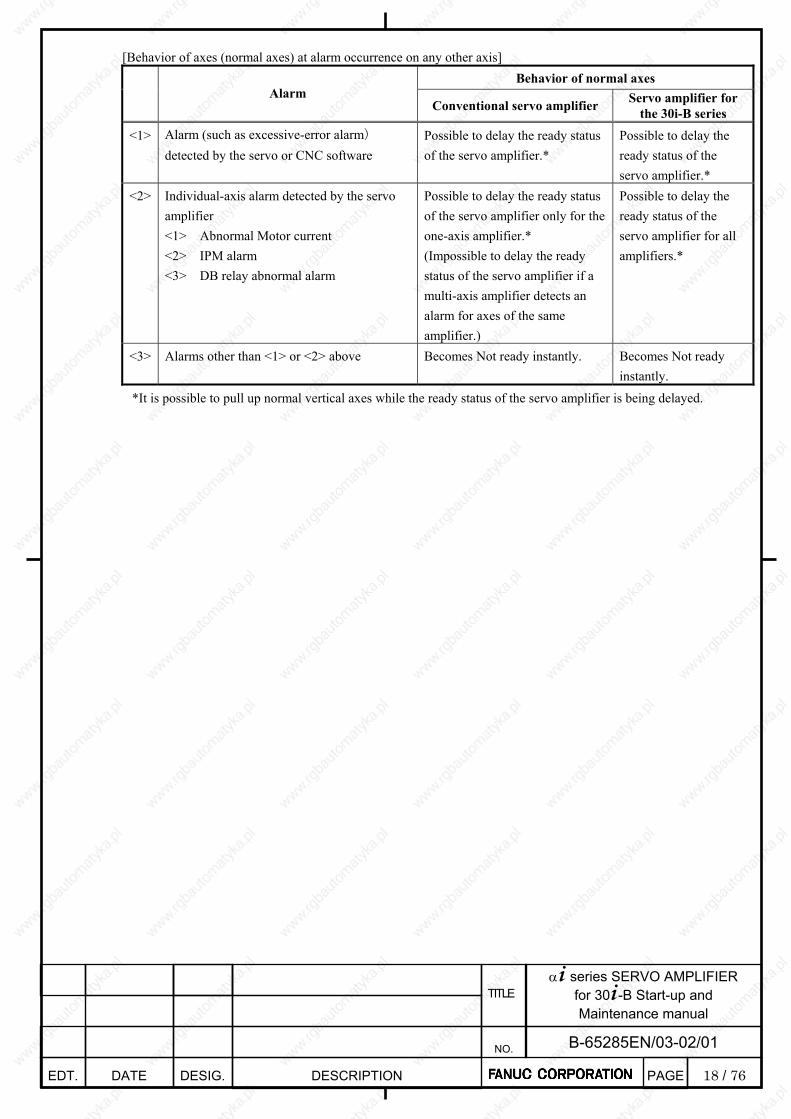
18 / 76
α+ series SERVO AMPLIFIER for 30+-B Start-up and Maintenance manual
EDT. DATE DESIG. DESCRIPTION
B-65285EN/03-02/01 NO.
TITLE
PAGE
[Behavior of axes (normal axes) at alarm occurrence on any other axis] Behavior of normal axes
Alarm Conventional servo amplifier Servo amplifier for
the 30i-B series
<1> Alarm (such as excessive-error alarm) detected by the servo or CNC software
Possible to delay the ready status of the servo amplifier.*
Possible to delay the ready status of the servo amplifier.*
<2> Individual-axis alarm detected by the servo amplifier <1> Abnormal Motor current <2> IPM alarm <3> DB relay abnormal alarm
Possible to delay the ready status of the servo amplifier only for the one-axis amplifier.* (Impossible to delay the ready status of the servo amplifier if a multi-axis amplifier detects an alarm for axes of the same amplifier.)
Possible to delay the ready status of the servo amplifier for all amplifiers.*
<3> Alarms other than <1> or <2> above Becomes Not ready instantly. Becomes Not ready instantly.
*It is possible to pull up normal vertical axes while the ready status of the servo amplifier is being delayed.

19 / 76
α+ series SERVO AMPLIFIER for 30+-B Start-up and Maintenance manual
EDT. DATE DESIG. DESCRIPTION
B-65285EN/03-02/01 NO.
TITLE
PAGE
・Supporting the axis detach function for multi-axis amplifiers
Conventionally, the axis detach function has been applicable only to axes driven by a one-axis servo amplifier. Now,
the detach function is applicable to each axis driven by the multi-axis servo amplifier for the 30i-B series.
・Setting dummy axes for multi-axis amplifiers Starting up a specific axis on the conventional multi-axis amplifier requires attaching a dummy connector to the axes not in use. With the servo amplifier for the 30i-B series, it is possible to start up only arbitrary axes. So, it is unnecessary to attach a dummy connector to any axis not in use.
・Sharing a multi-axis amplifier with two or more paths If the conventional multi-axis amplifier is shared among multiple paths, it is necessary to input a signal for ignoring the VRDY-OFF alarm when the amplifier becomes Not ready for an axis being used by one path, so that it will not become Not ready for axes in use by the other paths. For the servo amplifier for the 30i-B series, it is unnecessary to input such a signal.
CAUTION
1. Note on synchronization control and tandem control If an alarm occurs on one of the axes used on a multi-axis amplifier under synchronization or tandem control, it is necessary for the multi-axis amplifier to become Not ready immediately also for the other axes in order to prevent machine distortion. To meet this requirement, be sure to enable the servo software’s “servo alarm 2-axis simultaneous monitoring function” for axes under synchronization or tandem control. In some cases, implementing synchronization or tandem control for two axes driven by the conventional multi-axis amplifier caused the amplifier to be become Not ready for the two axes simultaneously at alarm occurrence as if the “servo alarm 2-axis simultaneous monitoring function” had operated. Because the ready status conditions of the multi-axis amplifier for the 30i-B series for each axis are independent of one another, using the multi-axis amplifier does not work in place of the “servo alarm 2-axis simultaneous monitoring function”. For this reason, be sure to enable the “servo alarm 2-axis simultaneous monitoring function” for axes under synchronization or tandem control also when the multi-axis amplifier is used. Refer to “Parameter Manual” for detailed descriptions of the “servo alarm 2-axis simultaneous monitoring function” and the related parameter setting.
2. If an alarm (such as a DC link low-voltage alarm) common to all axes occurs, any axis driven by the
multi-axis amplifier can be the cause of the alarm in the same manner as with the conventional amplifier, resulting in the amplifier becoming Not ready simultaneously for all axes and a dynamic brake being applied to all axes to bring them to halt.
3. If an emergency stop signal (input signal to the connector CX4 of the PS) is input, the amplifier
becomes Not ready for all axes and applies a dynamic brake to all axes to bring them to halt.

20 / 76
α+ series SERVO AMPLIFIER for 30+-B Start-up and Maintenance manual
EDT. DATE DESIG. DESCRIPTION
B-65285EN/03-02/01 NO.
TITLE
PAGE
1.2.3 SPINDLE AMPLIFIER
1.2.3.1 PARAMETER FOR SPINDLE SERIAL OUTPUT Only the list of parameters for SPINDLE SERIAL OUTPUT is mentioned. As for the detal of these parameter, refer to 11.2 “SPINDLE SERIAL OUTPUT” of FANUC Series 30+ / 31+ / 32+ –MODEL B CONNECTION MANUAL (FUNCTION)
Parameter
number 30i-B
Description
3716#0 (Analog/Serial)Selection of Spindle (Set to “1”)
3702#1 The multi-spindle control function (The multi-spindle control function is used
/not used) 3717 The spindle amplifier number of each spindle 3718 Subscript for display of spindle (main spindle) 3719 Subscript for display of spindle (sub-spindle)
Note When a serial spindle is used, the option for spindle serial
output is required.
About FSSB Setting, refer to 1.4.4「FSSB Setting」of FANUC Series 30+ / 31+ / 32+ –MODEL B CONNECTION MANUAL (FUNCTION).
1.2.3.2 Automatic Spindle Parameter Initialization
An automatic setup of spindle parameters (No.4000-No.4799) is described as follow.
Note When you do not want to initialize the adjusted parameters,
don’t perform automatic spindle parameter initialization.
1.2.3.2a Parameter List
Parameter No.
30i-B Description
4019#7 Function for automatically initializing spindle parameters.
4133 Spindle motor model code

21 / 76
α+ series SERVO AMPLIFIER for 30+-B Start-up and Maintenance manual
EDT. DATE DESIG. DESCRIPTION
B-65285EN/03-02/01 NO.
TITLE
PAGE
1.2.3.2b Procedure for automatic spindle parameter initialization Perform automatic spindle parameter initialization by following the procedure below. <1> Set the model code for the desired motor for automatic parameter initialization.
Parameter No. 30i-B
Description
4133 Model code
Note 1 The control method usable with the α+ series spindle is
spindleHRV control only. The conventional control method is not supported.
2 About the model code of each motor, refer to FANUC AC SPINDLE MOTOR α+ series PARAMETER
MANUAL B-65280JA. 3 When using a spindle motor that has no model code, set model
code “300” (“400” for a spindle motor with speed range switching control) for automatic parameter setting, then manually input data according to the parameter table for each motor model.
<2> Set the relevant parameter to enable automatic spindle parameter initialization.
Parameter No. 30i-B
Description
4019#7 1
Note This bit is reset to its original value after automatic parameter
initialization.
<3> Turn the CNC off, then on again. Then, the spindle parameters specified with a model code are automatically
initialized.
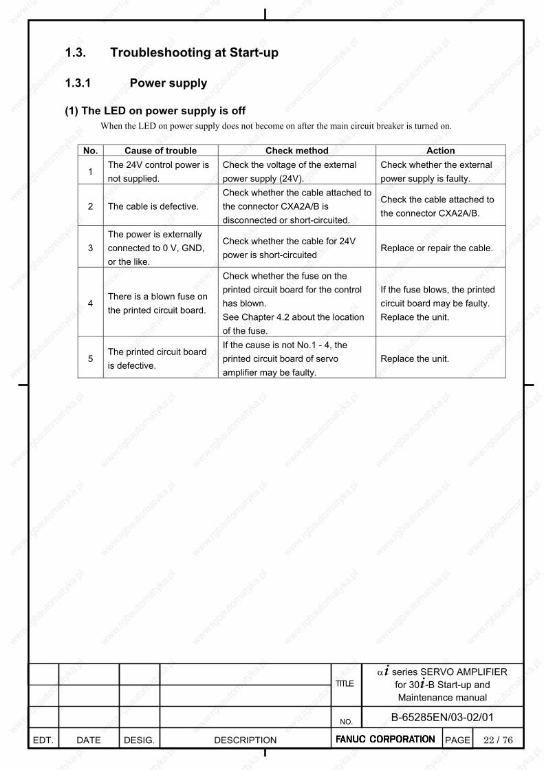
22 / 76
α+ series SERVO AMPLIFIER for 30+-B Start-up and Maintenance manual
EDT. DATE DESIG. DESCRIPTION
B-65285EN/03-02/01 NO.
TITLE
PAGE
1.3. Troubleshooting at Start-up 1.3.1 Power supply
(1) The LED on power supply is off
When the LED on power supply does not become on after the main circuit breaker is turned on.
No. Cause of trouble Check method Action
1 The 24V control power is not supplied.
Check the voltage of the external power supply (24V).
Check whether the external power supply is faulty.
2 The cable is defective. Check whether the cable attached to the connector CXA2A/B is disconnected or short-circuited.
Check the cable attached to the connector CXA2A/B.
3 The power is externally connected to 0 V, GND, or the like.
Check whether the cable for 24V power is short-circuited
Replace or repair the cable.
4 There is a blown fuse on the printed circuit board.
Check whether the fuse on the printed circuit board for the control has blown. See Chapter 4.2 about the location of the fuse.
If the fuse blows, the printed circuit board may be faulty. Replace the unit.
5 The printed circuit board is defective.
If the cause is not No.1 - 4, the printed circuit board of servo amplifier may be faulty.
Replace the unit.
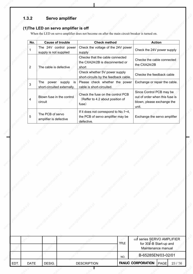
23 / 76
α+ series SERVO AMPLIFIER for 30+-B Start-up and Maintenance manual
EDT. DATE DESIG. DESCRIPTION
B-65285EN/03-02/01 NO.
TITLE
PAGE
1.3.2 Servo amplifier
(1)The LED on servo amplifier is off
When the LED on servo amplifier does not become on after the main circuit breaker is turned on.
No. Cause of trouble Check method Action
1 The 24V control power supply is not supplied
Check the voltage of the 24V power supply
Check the 24V power supply
Checke that the cable connected the CXA2A/2B is disconnented or short
Checke the cable connected the CXA2A/2B
2 The cable is defective Check whether 5V power supply short-circuits by the feedback cable.
Checke the feedback cable
3 The power supply is short-circuited externally.
Please check whether the power cable is short-circuited.
Exchange or repair the cable.
4 Blown fuse in the control circuit
Check the fuse on the control PCB (Reffer to 4.2 about position of fuse)
Since Control PCB may be out of order when this fuse is blown, please exchange the unit.
5 The PCB of servo amplifier is defective
If it does not correspond to No.1~4, the PCB of servo amplifier may be defective.
Exchange the servo amplifier
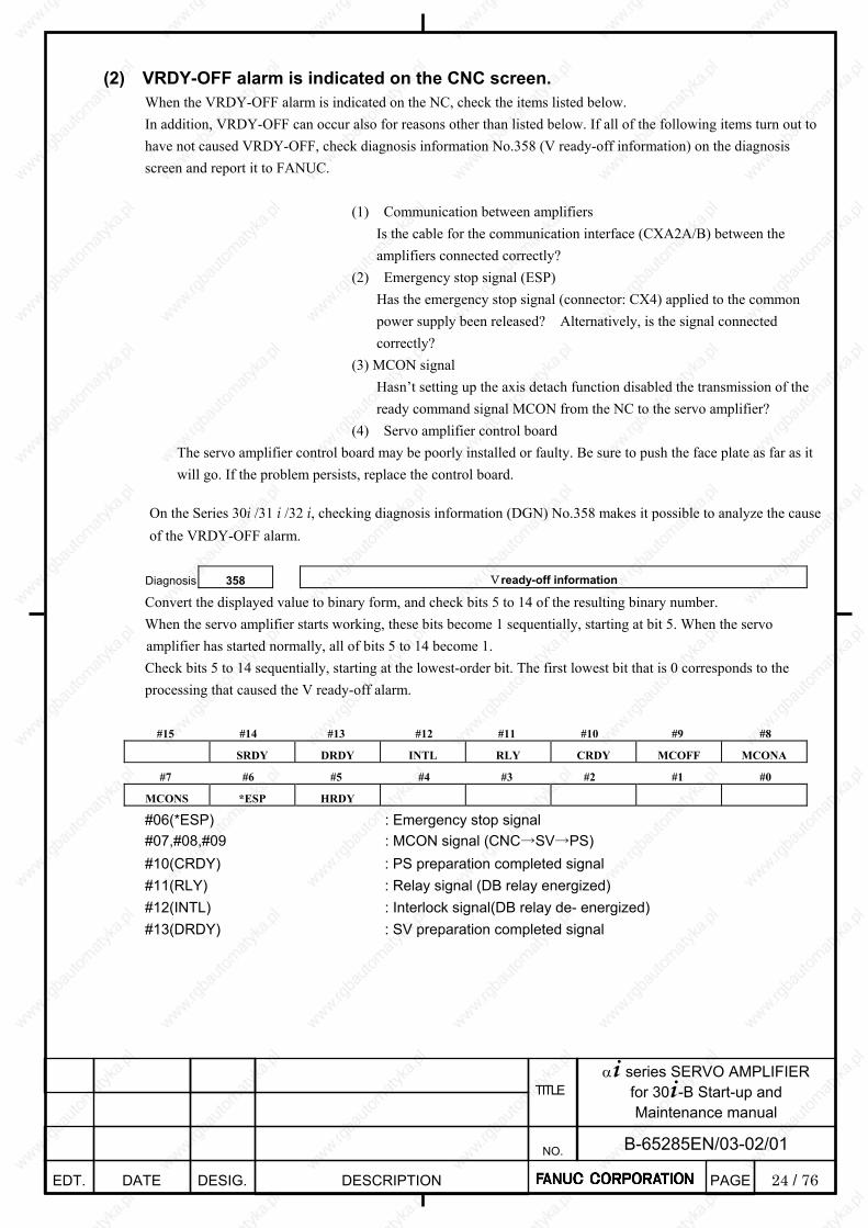
24 / 76
α+ series SERVO AMPLIFIER for 30+-B Start-up and Maintenance manual
EDT. DATE DESIG. DESCRIPTION
B-65285EN/03-02/01 NO.
TITLE
PAGE
(2) VRDY-OFF alarm is indicated on the CNC screen.
When the VRDY-OFF alarm is indicated on the NC, check the items listed below. In addition, VRDY-OFF can occur also for reasons other than listed below. If all of the following items turn out to have not caused VRDY-OFF, check diagnosis information No.358 (V ready-off information) on the diagnosis screen and report it to FANUC.
(1) Communication between amplifiers Is the cable for the communication interface (CXA2A/B) between the
amplifiers connected correctly? (2) Emergency stop signal (ESP) Has the emergency stop signal (connector: CX4) applied to the common
power supply been released? Alternatively, is the signal connected correctly?
(3) MCON signal Hasn’t setting up the axis detach function disabled the transmission of the
ready command signal MCON from the NC to the servo amplifier? (4) Servo amplifier control board
The servo amplifier control board may be poorly installed or faulty. Be sure to push the face plate as far as it will go. If the problem persists, replace the control board.
On the Series 30i /31 i /32 i, checking diagnosis information (DGN) No.358 makes it possible to analyze the cause of the VRDY-OFF alarm.
Diagnosis 358 Vready-off information
Convert the displayed value to binary form, and check bits 5 to 14 of the resulting binary number. When the servo amplifier starts working, these bits become 1 sequentially, starting at bit 5. When the servo amplifier has started normally, all of bits 5 to 14 become 1. Check bits 5 to 14 sequentially, starting at the lowest-order bit. The first lowest bit that is 0 corresponds to the processing that caused the V ready-off alarm.
#15 #14 #13 #12 #11 #10 #9 #8
SRDY DRDY INTL RLY CRDY MCOFF MCONA
#7 #6 #5 #4 #3 #2 #1 #0
MCONS *ESP HRDY
#06(*ESP) : Emergency stop signal #07,#08,#09 : MCON signal (CNC→SV→PS) #10(CRDY) : PS preparation completed signal #11(RLY) : Relay signal (DB relay energized) #12(INTL) : Interlock signal(DB relay de- energized) #13(DRDY) : SV preparation completed signal
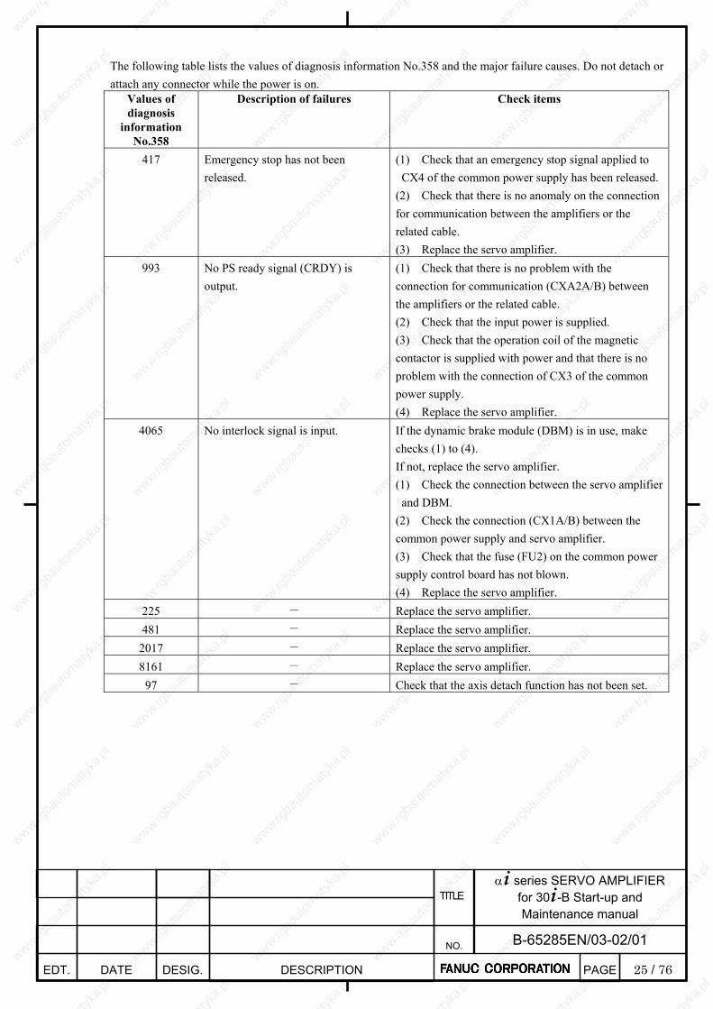
25 / 76
α+ series SERVO AMPLIFIER for 30+-B Start-up and Maintenance manual
EDT. DATE DESIG. DESCRIPTION
B-65285EN/03-02/01 NO.
TITLE
PAGE
The following table lists the values of diagnosis information No.358 and the major failure causes. Do not detach or attach any connector while the power is on.
Values of diagnosis
information No.358
Description of failures Check items
417 Emergency stop has not been released.
(1) Check that an emergency stop signal applied to CX4 of the common power supply has been released.
(2) Check that there is no anomaly on the connection for communication between the amplifiers or the related cable. (3) Replace the servo amplifier.
993 No PS ready signal (CRDY) is output.
(1) Check that there is no problem with the connection for communication (CXA2A/B) between the amplifiers or the related cable. (2) Check that the input power is supplied. (3) Check that the operation coil of the magnetic contactor is supplied with power and that there is no problem with the connection of CX3 of the common power supply. (4) Replace the servo amplifier.
4065 No interlock signal is input. If the dynamic brake module (DBM) is in use, make checks (1) to (4). If not, replace the servo amplifier. (1) Check the connection between the servo amplifier and DBM.
(2) Check the connection (CX1A/B) between the common power supply and servo amplifier. (3) Check that the fuse (FU2) on the common power supply control board has not blown. (4) Replace the servo amplifier.
225 - Replace the servo amplifier. 481 - Replace the servo amplifier.
2017 - Replace the servo amplifier. 8161 - Replace the servo amplifier.
97 - Check that the axis detach function has not been set.
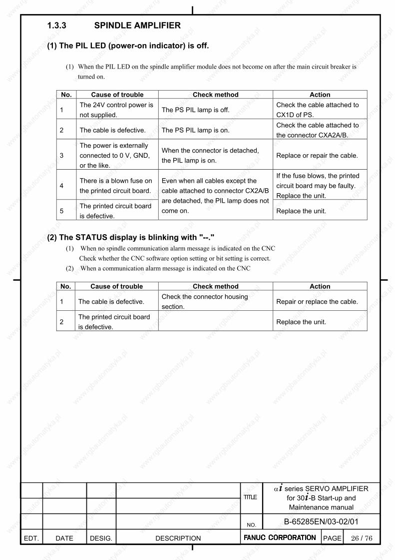
26 / 76
α+ series SERVO AMPLIFIER for 30+-B Start-up and Maintenance manual
EDT. DATE DESIG. DESCRIPTION
B-65285EN/03-02/01 NO.
TITLE
PAGE
1.3.3 SPINDLE AMPLIFIER
(1) The PIL LED (power-on indicator) is off.
(1) When the PIL LED on the spindle amplifier module does not become on after the main circuit breaker is turned on.
No. Cause of trouble Check method Action
1 The 24V control power is not supplied.
The PS PIL lamp is off. Check the cable attached to CX1D of PS.
2 The cable is defective. The PS PIL lamp is on. Check the cable attached to the connector CXA2A/B.
3 The power is externally connected to 0 V, GND, or the like.
When the connector is detached, the PIL lamp is on.
Replace or repair the cable.
4 There is a blown fuse on the printed circuit board.
If the fuse blows, the printed circuit board may be faulty. Replace the unit.
5 The printed circuit board is defective.
Even when all cables except the cable attached to connector CX2A/B are detached, the PIL lamp does not come on. Replace the unit.
(2) The STATUS display is blinking with "--."
(1) When no spindle communication alarm message is indicated on the CNC Check whether the CNC software option setting or bit setting is correct.
(2) When a communication alarm message is indicated on the CNC
No. Cause of trouble Check method Action
1 The cable is defective. Check the connector housing section.
Repair or replace the cable.
2 The printed circuit board is defective.
Replace the unit.
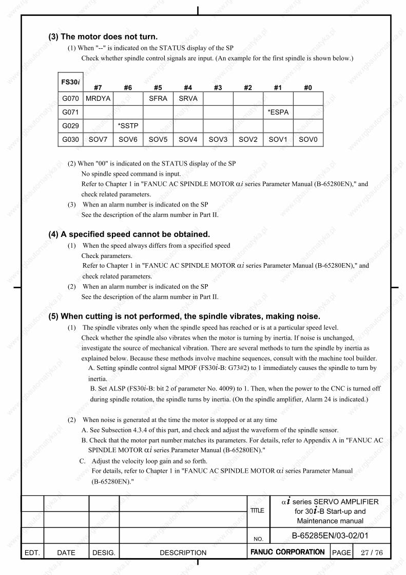
27 / 76
α+ series SERVO AMPLIFIER for 30+-B Start-up and Maintenance manual
EDT. DATE DESIG. DESCRIPTION
B-65285EN/03-02/01 NO.
TITLE
PAGE
(3) The motor does not turn.
(1) When "--" is indicated on the STATUS display of the SP Check whether spindle control signals are input. (An example for the first spindle is shown below.)
FS30i #7 #6 #5 #4 #3 #2 #1 #0
G070 MRDYA SFRA SRVA
G071 *ESPA
G029 *SSTP
G030 SOV7 SOV6 SOV5 SOV4 SOV3 SOV2 SOV1 SOV0
(2) When "00" is indicated on the STATUS display of the SP
No spindle speed command is input. Refer to Chapter 1 in "FANUC AC SPINDLE MOTOR αi series Parameter Manual (B-65280EN)," and check related parameters.
(3) When an alarm number is indicated on the SP See the description of the alarm number in Part II.
(4) A specified speed cannot be obtained.
(1) When the speed always differs from a specified speed Check parameters. Refer to Chapter 1 in "FANUC AC SPINDLE MOTOR αi series Parameter Manual (B-65280EN)," and check related parameters.
(2) When an alarm number is indicated on the SP See the description of the alarm number in Part II.
(5) When cutting is not performed, the spindle vibrates, making noise.
(1) The spindle vibrates only when the spindle speed has reached or is at a particular speed level. Check whether the spindle also vibrates when the motor is turning by inertia. If noise is unchanged, investigate the source of mechanical vibration. There are several methods to turn the spindle by inertia as explained below. Because these methods involve machine sequences, consult with the machine tool builder.
A. Setting spindle control signal MPOF (FS30i-B: G73#2) to 1 immediately causes the spindle to turn by inertia. B. Set ALSP (FS30i-B: bit 2 of parameter No. 4009) to 1. Then, when the power to the CNC is turned off during spindle rotation, the spindle turns by inertia. (On the spindle amplifier, Alarm 24 is indicated.)
(2) When noise is generated at the time the motor is stopped or at any time
A. See Subsection 4.3.4 of this part, and check and adjust the waveform of the spindle sensor. B. Check that the motor part number matches its parameters. For details, refer to Appendix A in "FANUC AC
SPINDLE MOTOR αi series Parameter Manual (B-65280EN)." C. Adjust the velocity loop gain and so forth.
For details, refer to Chapter 1 in "FANUC AC SPINDLE MOTOR αi series Parameter Manual (B-65280EN)."

28 / 76
α+ series SERVO AMPLIFIER for 30+-B Start-up and Maintenance manual
EDT. DATE DESIG. DESCRIPTION
B-65285EN/03-02/01 NO.
TITLE
PAGE
(6) An overshoot or hunting occurs.
Refer to Chapter 1 in "FANUC AC SPINDLE MOTOR αi series Parameter Manual (B-65280EN)," and adjust parameters.
(7) Cutting power weakens or acceleration/deceleration slows down. (1) When the load meter does not indicate the maximum output
A. A mechanical cause such as a belt slip may occur. (2) When the load meter indicates the maximum output
A. Check whether the torque limit signal is input incorrectly.
FS30i #7 #6 #5 #4 #3 #2 #1 #0
G070 TLMHA TLMLA
B. If you are using the αi BZ sensor, it is likely that a slip has occurred between the sensor gear and spindle (on acceleration). C. Check that the motor part number matches its parameters.
For details, refer to Appendix A in "FANUC AC SPINDLE MOTOR αi series Parameter Manual (B-65280EN)." D. Check whether the output limit pattern is set incorrectly.
For details, refer to Chapter 1 in "FANUC AC SPINDLE MOTOR αi series Parameter Manual (B-65280EN)."
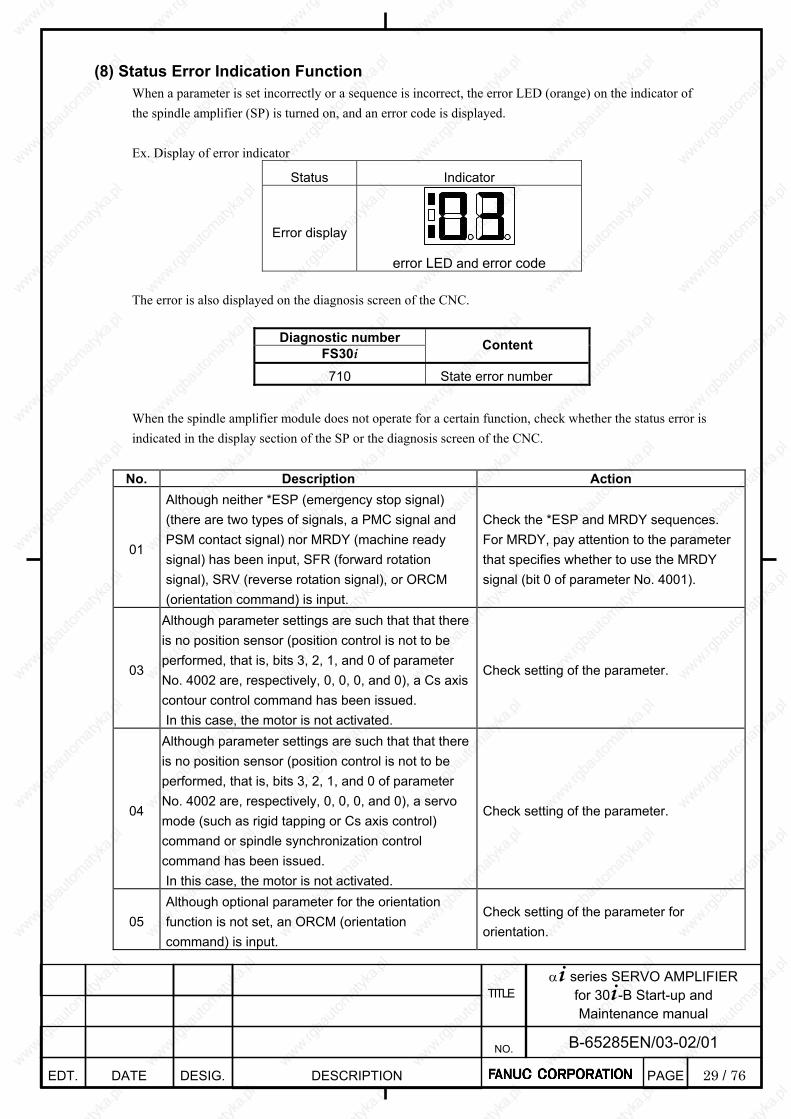
29 / 76
α+ series SERVO AMPLIFIER for 30+-B Start-up and Maintenance manual
EDT. DATE DESIG. DESCRIPTION
B-65285EN/03-02/01 NO.
TITLE
PAGE
(8) Status Error Indication Function
When a parameter is set incorrectly or a sequence is incorrect, the error LED (orange) on the indicator of the spindle amplifier (SP) is turned on, and an error code is displayed. Ex. Display of error indicator
Status Indicator
Error display
error LED and error code
The error is also displayed on the diagnosis screen of the CNC.
Diagnostic number FS30i Content
710 State error number When the spindle amplifier module does not operate for a certain function, check whether the status error is indicated in the display section of the SP or the diagnosis screen of the CNC.
No. Description Action
01
Although neither *ESP (emergency stop signal) (there are two types of signals, a PMC signal and PSM contact signal) nor MRDY (machine ready signal) has been input, SFR (forward rotation signal), SRV (reverse rotation signal), or ORCM (orientation command) is input.
Check the *ESP and MRDY sequences. For MRDY, pay attention to the parameter that specifies whether to use the MRDY signal (bit 0 of parameter No. 4001).
03
Although parameter settings are such that that there is no position sensor (position control is not to be performed, that is, bits 3, 2, 1, and 0 of parameter No. 4002 are, respectively, 0, 0, 0, and 0), a Cs axis contour control command has been issued. In this case, the motor is not activated.
Check setting of the parameter.
04
Although parameter settings are such that that there is no position sensor (position control is not to be performed, that is, bits 3, 2, 1, and 0 of parameter No. 4002 are, respectively, 0, 0, 0, and 0), a servo mode (such as rigid tapping or Cs axis control) command or spindle synchronization control command has been issued. In this case, the motor is not activated.
Check setting of the parameter.
05 Although optional parameter for the orientation function is not set, an ORCM (orientation command) is input.
Check setting of the parameter for orientation.

30 / 76
α+ series SERVO AMPLIFIER for 30+-B Start-up and Maintenance manual
EDT. DATE DESIG. DESCRIPTION
B-65285EN/03-02/01 NO.
TITLE
PAGE
No. Description Action
06 Although optional parameter for the output switching option is not set, low-speed winding is selected (RCH = 1).
Check setting of the parameter for output switching and the power line status signal (RCH).
07 Although Cs contour control mode is input, neither SFR (forward rotation signal) nor SRV (reverse rotation signal) is input.
Check the sequence.
08
Although servo mode (rigid tapping or spindle positioning) control command is input, neither SFR (forward rotation signal) nor SRV (reverse rotation signal) is input.
Check the sequence.
09 Although spindle synchronization control command is input, neither SFR (forward rotation signal) nor SRV (reverse rotation signal) is input.
Check the sequence.
10 Although Cs contour control command is input, another operation mode (servo mode, spindle synchronization, or orientation) is specified.
Do not specify another mode during execution of the Cs contour control command. Before entering another mode, cancel the Cs contour control command.
11 Although servo mode (rigid tapping or spindle positioning) is input, another operation mode (Cs contour control, spindle synchronization, or orientation) is specified.
Do not specify another mode during execution of the servo mode command. Before entering another mode, cancel servo mode.
12 Although spindle synchronization is input, another operation mode (Cs contour control, servo mode, or orientation) is specified.
Do not specify another mode during execution of the spindle synchronization command. Before entering another mode, cancel the spindle synchronization command.
13 Although orientation specification is input, another operation mode (Cs contour control, servo mode, or synchronization control) is specified.
Do not specify another mode during execution of the spindle synchronization command. Before entering another mode, cancel the spindle synchronization command.
14 The SFR (forward rotation signal) and SRV (reverse rotation signal) are input at the same time.
Input one of the SFR and SRV signals.
16 Although the parameter not to use the differential speed control function (bit 5 of parameter No. 4000 = 0) is set, DEFMD (differential speed mode command) is input.
Check the setting of the parameter and the differential speed mode command
17 The parameter settings for the speed detector (bits 2, 1, and 0 of parameter No. 4011) are invalid. There is no speed detector that matches the settings.
Check the setting of the parameter.
31 / 76
α+ series SERVO AMPLIFIER for 30+-B Start-up and Maintenance manual
EDT. DATE DESIG. DESCRIPTION
B-65285EN/03-02/01 NO.
TITLE
PAGE
No. Description Action 18 Although parameter settings are such that that
there is no position sensor (position control is not to be performed, that is, "bits 3, 2, 1, and 0 of parameter No. 4002 are, respectively, 0, 0, 0, and 0," a position coder-based orientation command has been issued.
Check the setting of the parameter and the input signal.
19 Although magnetic sensor orientation command is input, another operation mode (Cs contour control, servo mode, or spindle synchronization) is specified.
Do not specify another mode during execution of the orientation command. Before entering another mode, cancel the orientation command.
21 A tandem operation command was input when spindle synchronous control is enabled.
Input a tandem operation command after canceling spindle synchronous control.
22 Spindle synchronous control was specified when tandem operation is enabled.
Specify spindle synchronous control after canceling torque tandem operation.
23 A tandem operation command is input even if the option is not specified.
Torque tandem control requires the CNC software option. Check the option.
24 Although continuous indexing in position coder-based orientation is to be performed, an absolute position command (INCMD = 0) has been issued after incremental operation (INCMD = 1).
Check the INCMD (incremental command).Be sure to perform absolute position command-based orientation before an absolute position command.
26 Parameter settings are made to use both spindle switching and three stage speed range switching control.
Check the parameter settings and input signals.
29 Parameter settings are such that the shortest-time orientation function is to be used (bit 6 of parameter No. 4018 is 0 and parameter Nos. 4320 to 4323 are nonzero).
The shortest-time orientation function cannot be used in the αi series spindle amplifier. Use a different type of orientation.
30 The magnetic pole undetected state is set, but a command is input.
In the magnetic pole undetected state (EPFIXA=0), the motor cannot be driven even if a command is input. input a command in the magnetic pole detection completed state (EPFIXA=1). While EPFSTR=1 is set, a command is ignored even in the magnetic pole detection completed state, and this error is indicated. Upon completion of magnetic pole detection, set EPFSTR=0.
31 This hardware configuration does not support the use of the spindle FAD function. In this case, the motor is not activated.
Check the CNC model.
32 Although S0 is not specified for the speed mode, the parameter setting is made to enable the disturbance input function (bit 7 of parameter No.4395 =1).
Specify S0 for the speed mode before enabling the disturbance input function ( setting bit 7 of parameter No.4395 to 1).
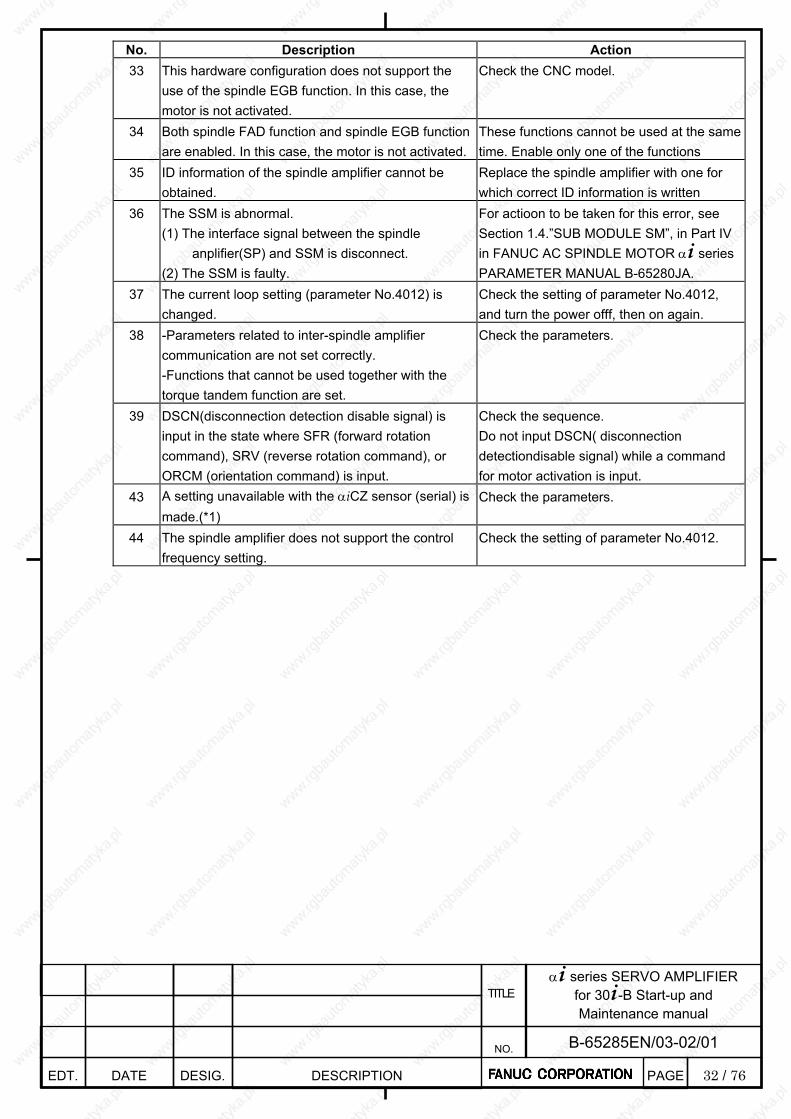
32 / 76
α+ series SERVO AMPLIFIER for 30+-B Start-up and Maintenance manual
EDT. DATE DESIG. DESCRIPTION
B-65285EN/03-02/01 NO.
TITLE
PAGE
No. Description Action 33 This hardware configuration does not support the
use of the spindle EGB function. In this case, the motor is not activated.
Check the CNC model.
34 Both spindle FAD function and spindle EGB function are enabled. In this case, the motor is not activated.
These functions cannot be used at the same time. Enable only one of the functions
35 ID information of the spindle amplifier cannot be obtained.
Replace the spindle amplifier with one for which correct ID information is written
36 The SSM is abnormal. (1) The interface signal between the spindle
anplifier(SP) and SSM is disconnect. (2) The SSM is faulty.
For actioon to be taken for this error, see Section 1.4.”SUB MODULE SM”, in Part IV in FANUC AC SPINDLE MOTOR α+ series PARAMETER MANUAL B-65280JA.
37 The current loop setting (parameter No.4012) is changed.
Check the setting of parameter No.4012, and turn the power offf, then on again.
38 -Parameters related to inter-spindle amplifier communication are not set correctly. -Functions that cannot be used together with the torque tandem function are set.
Check the parameters.
39 DSCN(disconnection detection disable signal) is input in the state where SFR (forward rotation command), SRV (reverse rotation command), or ORCM (orientation command) is input.
Check the sequence. Do not input DSCN( disconnection detectiondisable signal) while a command for motor activation is input.
43 A setting unavailable with the αiCZ sensor (serial) is made.(*1)
Check the parameters.
44 The spindle amplifier does not support the control frequency setting.
Check the setting of parameter No.4012.

33 / 76
α+ series SERVO AMPLIFIER for 30+-B Start-up and Maintenance manual
EDT. DATE DESIG. DESCRIPTION
B-65285EN/03-02/01 NO.
TITLE
PAGE
Note *1 If state error 43 is displayed, check the following items. <1> The setting is made so that the αiCZ sensor (serial) is used as both of the motor and
spindlesensors. (No.4010#2,1,0=0,1,0 and No.4002#3,2,1,0=0,1,1,0) <2> Spindle HRV control is not set. (No.4012#7=0) <3> The use of the differential spindle speed control function is set. (No.4000#5=1) <4> The use of the spindle switching control function is set. (No.4014#0=1) <5> The setting is made so that alarms related to position feedback are not detected.
(No.4007#6=1 or No.4016#5=0) <6> The setting is made so that feedback signal disconnection is not detected. (No.4007#5=1) <7> The setting is made so that alarms related to threading position detection signal feedback
arenot detected. (No.4016#5=0) <8> The use of an external one-rotation signal is set. (No.4004#2=1) <9> The use of a position coder is set. (No.4002#3,2,1,0=0,0,1,0) <10> The setting is made so that the synchronous built-in spindle motor is driven.
(No.4012#6=1) <11> The use of inter-spindle amplifier communication is set. (No.4352#7=1 or No.4352#6=1) <12> The use of the dual check safety function is set. <13> The use of the spindle tandem function is set. (No.4015#3=1) <14> The use of the αi CZ sensor (serial) as the motor sensor is set and the dual check safety
function is enabled.

34 / 76
α+ series SERVO AMPLIFIER for 30+-B Start-up and Maintenance manual
EDT. DATE DESIG. DESCRIPTION
B-65285EN/03-02/01 NO.
TITLE
PAGE
2. TROUBLESHOOTING
2.1. TROUBLESHOOTING PROCEDURES
2.1.1 Troubleshooting Procedure
Smart trouble shooting function is available for the combination of the 30+-B series CNC and the α+ servo amplifier for the 30+-B series. The function analyzes causes of alarm occurrence and shows how to remove them. At alarm occurrence, switch from he CNC screen to the “Trouble diagnosis guidance” screen and remove the cause of the alarm according to what is displayed on the screen. ⇒ 2.2 SMART TROUBLE SHOOTING FUNCTION ⇒ 2.2.1 Failure Diagnosis Guidance
IMPORTANT ・ Using the failure diagnosis guidance requires keeping it in the “SAMPLING” status. See
Subsection 2.2.3 for explanations about how to shift to the “SAMPLING” status. Data (about power supply, motor current, and detector) related to servo amplifiers before alarm and just at alarm are sent to the CNC immediately. This data can be used in taking action for alarm occurrence. Data (about power supply, motor current, and detector) related to servo amplifiers is saved to the CNC immediately before and at alarm occurrence. This data can be used in taking action for alarm occurrence. ⇒ 2.2.2 Failure Diagnosis Monitor
IMPORTANT ・ The failure diagnosis monitor has two status, “SAMPLING” and “LATCHED”.
If you want to monitor data at future alarm occurrence, perform “CLEAR”. If you want to save the conditions at past alarm occurrence, do not perform “CLEAR”. See Subsection 2.2.3 for detailed descriptions of this procedure.
See Section 2.3 for lists of CNC alarm numbers related to servos and LED indication numbers on servo amplifiers.
NOTE ・ There might be a possibility that you cannot get exact analysis even when you use smart
trouble shooting function. In such case, identify the alarm number, the program where the alarm occur, and what you operated, and then make a service call.
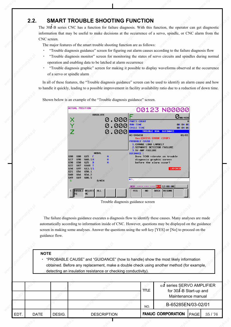
35 / 76
α+ series SERVO AMPLIFIER for 30+-B Start-up and Maintenance manual
EDT. DATE DESIG. DESCRIPTION
B-65285EN/03-02/01 NO.
TITLE
PAGE
2.2. SMART TROUBLE SHOOTING FUNCTION The 30+-B series CNC has a function for failure diagnosis. With this function, the operator can get diagnostic information that may be useful to make decisions at the occurrence of a servo, spindle, or CNC alarm from the CNC screen. The major features of the smart trouble shooting function are as follows: ・ “Trouble diagnosis guidance” screen for figuring out alarm causes according to the failure diagnosis flow ・ “Trouble diagnosis monitor” screen for monitoring the states of servo circuits and spindles during normal
operation and enabling data to be latched at alarm occurrence ・ “Trouble diagnosis graphic” screen for making it possible to display waveforms observed at the occurrence
of a servo or spindle alarm
In all of these features, the “Trouble diagnosis guidance” screen can be used to identify an alarm cause and how to handle it quickly, leading to a possible improvement in facility availability ratio due to a reduction of down time.
Shown below is an example of the “Trouble diagnosis guidance” screen.
Trouble diagnosis guidance screen
The failure diagnosis guidance executes a diagnosis flow to identify these causes. Many analyses are made
automatically according to information inside of CNC. However, questions may be displayed on the guidance screen in making some analyses. Answer the questions using the soft key [YES] or [No] to proceed on the guidance flow.
NOTE ・ “PROBABLE CAUSE” and “GUIDANCE” (how to handle) show the most likely information
obtained. Before any replacement, make a double check using another method (for example, detecting an insulation resistance or checking conductivity).
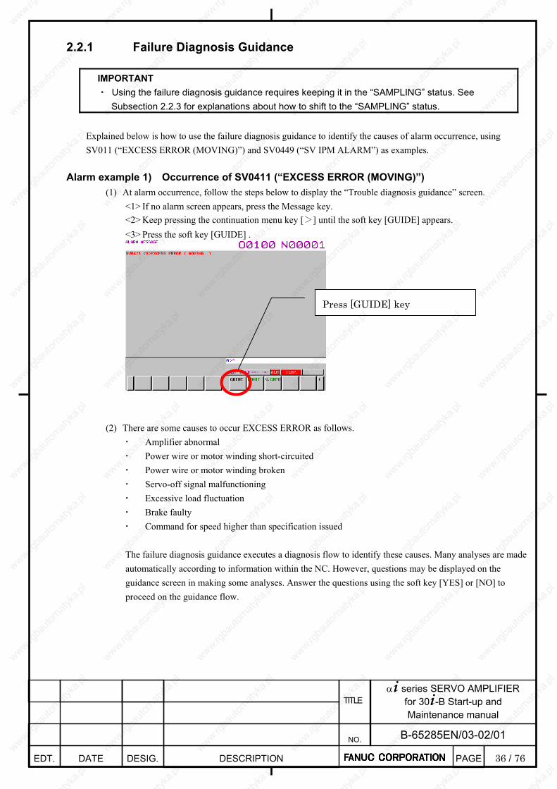
36 / 76
α+ series SERVO AMPLIFIER for 30+-B Start-up and Maintenance manual
EDT. DATE DESIG. DESCRIPTION
B-65285EN/03-02/01 NO.
TITLE
PAGE
2.2.1 Failure Diagnosis Guidance
IMPORTANT ・ Using the failure diagnosis guidance requires keeping it in the “SAMPLING” status. See
Subsection 2.2.3 for explanations about how to shift to the “SAMPLING” status.
Explained below is how to use the failure diagnosis guidance to identify the causes of alarm occurrence, using SV011 (“EXCESS ERROR (MOVING)”) and SV0449 (“SV IPM ALARM”) as examples.
Alarm example 1) Occurrence of SV0411 (“EXCESS ERROR (MOVING)”) (1) At alarm occurrence, follow the steps below to display the “Trouble diagnosis guidance” screen.
<1> If no alarm screen appears, press the Message key. <2> Keep pressing the continuation menu key [>] until the soft key [GUIDE] appears. <3> Press the soft key [GUIDE] .
(2) There are some causes to occur EXCESS ERROR as follows. Amplifier abnormal Power wire or motor winding short-circuited Power wire or motor winding broken Servo-off signal malfunctioning Excessive load fluctuation Brake faulty Command for speed higher than specification issued
The failure diagnosis guidance executes a diagnosis flow to identify these causes. Many analyses are made automatically according to information within the NC. However, questions may be displayed on the guidance screen in making some analyses. Answer the questions using the soft key [YES] or [NO] to proceed on the guidance flow.
Press [GUIDE] key
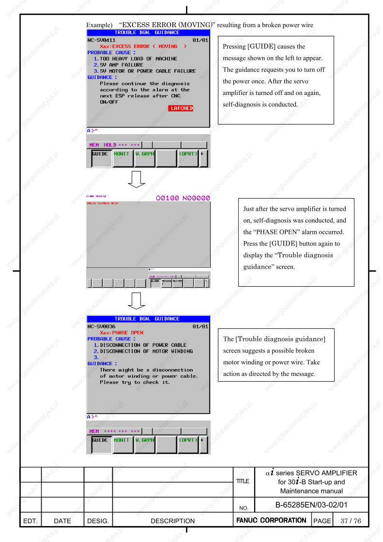
37 / 76
α+ series SERVO AMPLIFIER for 30+-B Start-up and Maintenance manual
EDT. DATE DESIG. DESCRIPTION
B-65285EN/03-02/01 NO.
TITLE
PAGE
Example) “EXCESS ERROR (MOVING)” resulting from a broken power wire
Pressing [GUIDE] causes the
message shown on the left to appear.
The guidance requests you to turn off
the power once. After the servo
amplifier is turned off and on again,
self-diagnosis is conducted.
Just after the servo amplifier is turned
on, self-diagnosis was conducted, and
the “PHASE OPEN” alarm occurred.
Press the [GUIDE] button again to
display the “Trouble diagnosis guidance” screen.
The [Trouble diagnosis guidance]
screen suggests a possible broken
motor winding or power wire. Take
action as directed by the message.
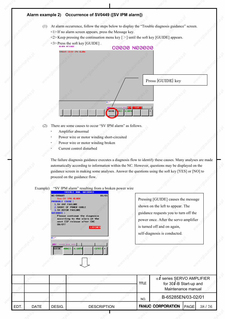
38 / 76
α+ series SERVO AMPLIFIER for 30+-B Start-up and Maintenance manual
EDT. DATE DESIG. DESCRIPTION
B-65285EN/03-02/01 NO.
TITLE
PAGE
Alarm example 2) Occurrence of SV0449 ([SV IPM alarm])
(1) At alarm occurrence, follow the steps below to display the “Trouble diagnosis guidance” screen. <1> If no alarm screen appears, press the Message key. <2> Keep pressing the continuation menu key [>] until the soft key [GUIDE] appears. <3> Press the soft key [GUIDE] .
(2) There are some causes to occur “SV IPM alarm” as follows. Amplifier abnormal Power wire or motor winding short-circuited Power wire or motor winding broken Current control disturbed
The failure diagnosis guidance executes a diagnosis flow to identify these causes. Many analyses are made automatically according to information within the NC. However, questions may be displayed on the guidance screen in making some analyses. Answer the questions using the soft key [YES] or [NO] to proceed on the guidance flow.
Example) “SV IPM alarm” resulting from a broken power wire
Press [GUIDE] key
Pressing [GUIDE] causes the message
shown on the left to appear. The
guidance requests you to turn off the
power once. After the servo amplifier
is turned off and on again,
self-diagnosis is conducted.
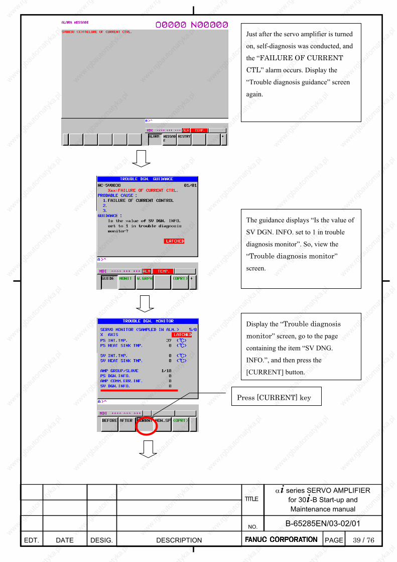
39 / 76
α+ series SERVO AMPLIFIER for 30+-B Start-up and Maintenance manual
EDT. DATE DESIG. DESCRIPTION
B-65285EN/03-02/01 NO.
TITLE
PAGE
Just after the servo amplifier is turned
on, self-diagnosis was conducted, and
the “FAILURE OF CURRENT CTL” alarm occurs. Display the
“Trouble diagnosis guidance” screen
again.
The guidance displays “Is the value of
SV DGN. INFO. set to 1 in trouble
diagnosis monitor”. So, view the
“Trouble diagnosis monitor”
screen.
Display the “Trouble diagnosis monitor” screen, go to the page
containing the item “SV DNG.
INFO.”, and then press the
[CURRENT] button.
Press [CURRENT] key
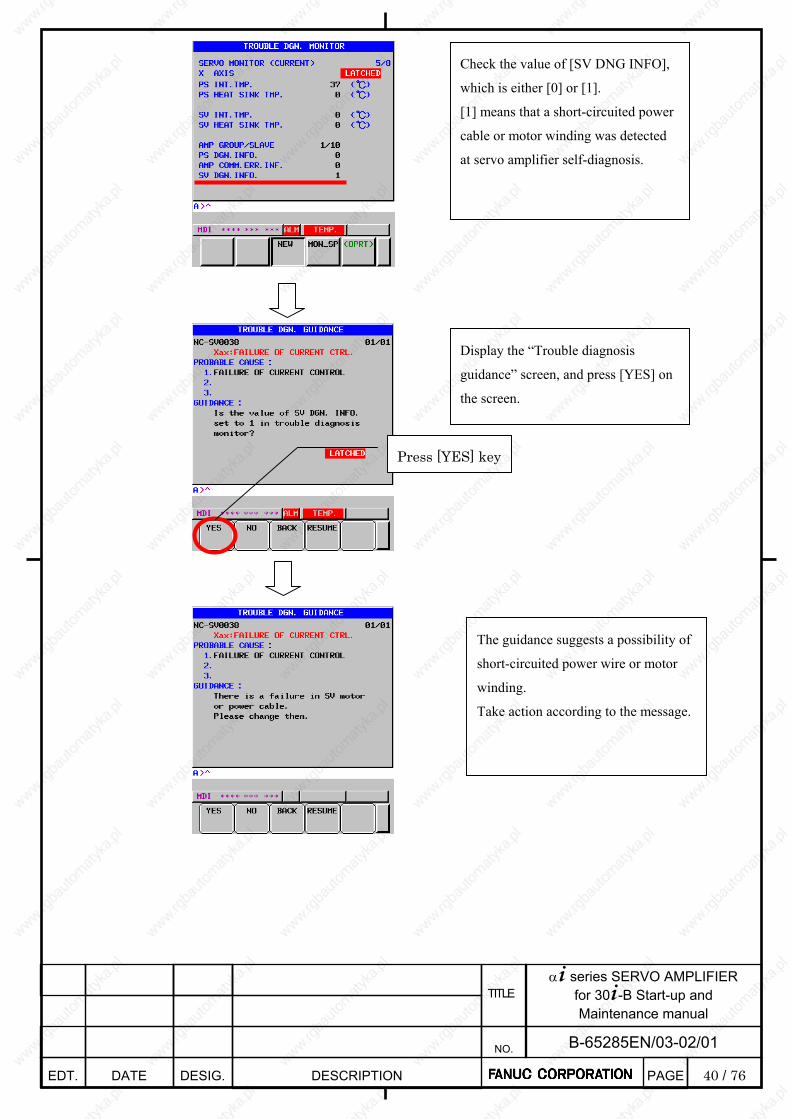
40 / 76
α+ series SERVO AMPLIFIER for 30+-B Start-up and Maintenance manual
EDT. DATE DESIG. DESCRIPTION
B-65285EN/03-02/01 NO.
TITLE
PAGE
Check the value of [SV DNG INFO],
which is either [0] or [1].
[1] means that a short-circuited power
cable or motor winding was detected
at servo amplifier self-diagnosis.
Display the “Trouble diagnosis
guidance” screen, and press [YES] on
the screen.
Press [YES] key
The guidance suggests a possibility of
short-circuited power wire or motor
winding.
Take action according to the message.
41 / 76
α+ series SERVO AMPLIFIER for 30+-B Start-up and Maintenance manual
EDT. DATE DESIG. DESCRIPTION
B-65285EN/03-02/01 NO.
TITLE
PAGE
2.2.2 Failure Diagnosis Monitor
IMPORTANT ・ The failure diagnosis monitor has two status, “SAMPLING” and “LATCHED”.
If you want to monitor data at future alarm occurrence, perform “CLEAR”. If you want to save the conditions at past alarm occurrence, do not perform “CLEAR”. See Subsection 2.2.3 for detailed descriptions of this procedure.
The failure diagnosis monitor can display the following information. Follow the steps below to display the “Trouble diagnosis monitor” screen. ・ Press the Message key to display the alarm screen. ・ Keep pressing the continuation menu key [>] until the soft key [MONIT] appears. ・ Press the soft key [MONIT] to display the “Trouble diagnosis monitor” screen.
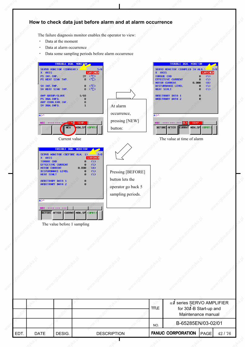
42 / 76
α+ series SERVO AMPLIFIER for 30+-B Start-up and Maintenance manual
EDT. DATE DESIG. DESCRIPTION
B-65285EN/03-02/01 NO.
TITLE
PAGE
How to check data just before alarm and at alarm occurrence
The failure diagnosis monitor enables the operator to view: ・ Data at the moment ・ Data at alarm occurrence ・ Data some sampling periods before alarm occurrence
Current value The value at time of alarm
The value before 1 sampling
At alarm
occurrence,
pressing [NEW]
button:
Pressing [BEFORE]
button lets the
operator go back 5
sampling periods.

43 / 76
α+ series SERVO AMPLIFIER for 30+-B Start-up and Maintenance manual
EDT. DATE DESIG. DESCRIPTION
B-65285EN/03-02/01 NO.
TITLE
PAGE
Details of the monitor screens related to servo amplifiers
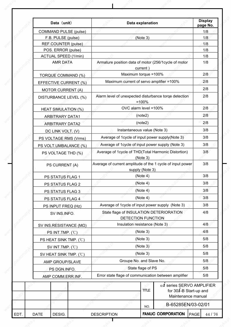
44 / 76
α+ series SERVO AMPLIFIER for 30+-B Start-up and Maintenance manual
EDT. DATE DESIG. DESCRIPTION
B-65285EN/03-02/01 NO.
TITLE
PAGE
Data(unit) Data explanation Display page No.
COMMAND PULSE (pulse) 1/8 F.B. PULSE (pulse) (Note 3) 1/8
REF.COUNTER (pulse) 1/8 POS. ERROR (pulse) 1/8
ACTUAL SPEED (1/min) 1/8 AMR DATA Armature position data of motor (256/1cycle of motor
current ) 1/8
TORQUE COMMAND (%) Maximum torque =100% 2/8
EFFECTIVE CURRENT (%) Maximum current of servo amplifier =100% 2/8
MOTOR CURRENT (A) 2/8
DISTURBANCE LEVEL (%) Alarm level of unexpected disturbance torqe detection =100%
2/8
HEAT SIMULATION (%) OVC alarm level =100% 2/8
ARBITRARY DATA1 (note2) 2/8
ARBITRARY DATA2 (note2) 2/8
DC LINK VOLT. (V) Instantaneous value (Note 3) 3/8
PS VOLTAGE RMS (Vrms) Average of 1cycle of input power supply(Note 3) 3/8
PS VOLT.UMBALANCE (%) Average of 1cycle of input power supply (Note 3) 3/8
PS VOLTAGE THD (%) Average of 1cycle of THD(Total Harmonic Distortion) (Note 3)
3/8
PS CURRENT (A) Average of current amplitude of the 1 cycle of input power supply (Note 3)
3/8
PS STATUS FLAG 1 (Note 4) 3/8
PS STATUS FLAG 2 (Note 4) 3/8
PS STATUS FLAG 3 (Note 4) 3/8
PS STATUS FLAG 4 (Note 4) 3/8
PS INPUT FREQ (Hz) Average of 1cycle of input power supply (Note 3) 3/8
SV INS.INFO. State flage of INSULATION DETERIORATION DETECTION FUNCTION
4/8
SV INS.RESISTANCE (MΩ) Insulation resistance (Note 3) 4/8
PS INT.TMP. () (Note 3) 4/8
PS HEAT SINK TMP. () (Note 3) 5/8
SV INT.TMP. () (Note 3) 5/8
SV HEAT SINK TMP. () (Note 3) 5/8
AMP GROUP/SLAVE Groupe No. and Slave No. 5/8
PS DGN.INFO. State flage of PS 5/8
AMP COMM.ERR.INF. Error state flage of communication between amplifier 5/8

45 / 76
α+ series SERVO AMPLIFIER for 30+-B Start-up and Maintenance manual
EDT. DATE DESIG. DESCRIPTION
B-65285EN/03-02/01 NO.
TITLE
PAGE
SV DGN.INFO. State flage of SV 5/8
SV FSSB UPR.ERR. (Note 5) 6/8
SV FSSB LWR.ERR. (Note 5) 6/8
SV FSSB UPR.JTR. (Note 5) 6/8
SV FSSB LWR.JTR. (Note 5) 6/8
SDU FSSB UPR.ERR. (Note 5) 6/8
SDU FSSB LWR.ERR. (Note 5) 6/8
SDU FSSB UPR.JTR. (Note 5) 6/8
SDU FSSB LWR.JTR. (Note 5) 6/8
INT.DTCT.INTP.CNT The number of times by which the data of a built-in detector was disturbed in the noise
(The number of times which detected the abnormalities in data)
7/8
INT.DTCT.COM.CNT The number of times which detected the abnormalities in data of a built-in detector
(The number of times which detected the communication error)
7/8
INT.DETECTOR WRN. Warning information of a built-in detector 7/8
EXT.DTCT.INTP.CNT The number of times by which the data of a separated detector was disturbed in the noise
(The number of times which detected the abnormalities in data)
7/8
EXT.DTCT.COM.CNT The number of times which detected the abnormalities in data of a separated detector
(The number of times which detected the communication error)
7/8
EXT.DETECTOR WRN. Warning information of a separated detector 7/8
SV DATA 1 (Note 2) 7/8
SV DATA 2 (Note 2) 7/8
SV DATA 3 (Note 2) 7/8
SV DATA 4 (Note 2) 7/8
LAST LATCH DATE 8/8 LAST LATCH TIME 8/8
EXECUTED FILE NAME 8/8 EXECUTED N-NUM 8/8
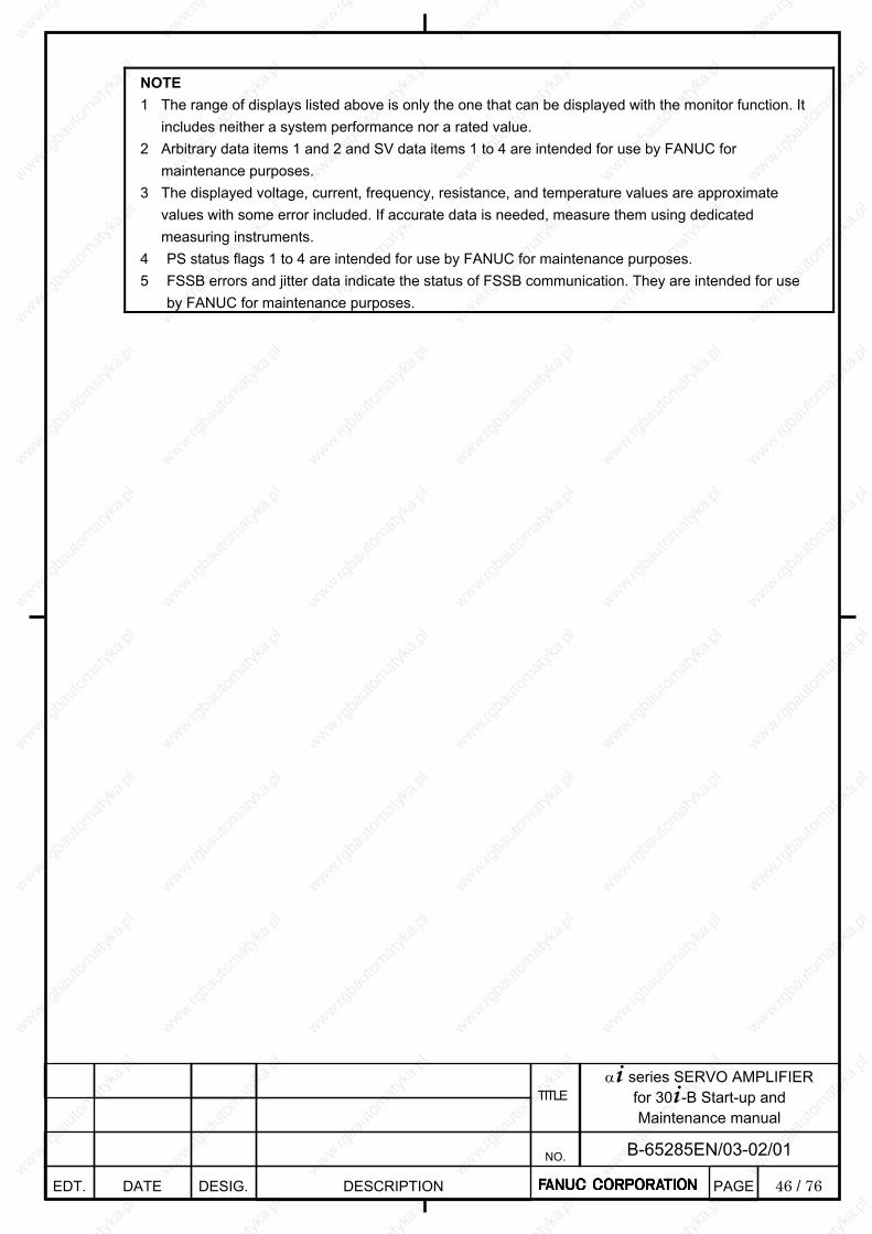
46 / 76
α+ series SERVO AMPLIFIER for 30+-B Start-up and Maintenance manual
EDT. DATE DESIG. DESCRIPTION
B-65285EN/03-02/01 NO.
TITLE
PAGE
NOTE 1 The range of displays listed above is only the one that can be displayed with the monitor function. It
includes neither a system performance nor a rated value. 2 Arbitrary data items 1 and 2 and SV data items 1 to 4 are intended for use by FANUC for
maintenance purposes. 3 The displayed voltage, current, frequency, resistance, and temperature values are approximate
values with some error included. If accurate data is needed, measure them using dedicated measuring instruments.
4 PS status flags 1 to 4 are intended for use by FANUC for maintenance purposes. 5 FSSB errors and jitter data indicate the status of FSSB communication. They are intended for use
by FANUC for maintenance purposes.

47 / 76
α+ series SERVO AMPLIFIER for 30+-B Start-up and Maintenance manual
EDT. DATE DESIG. DESCRIPTION
B-65285EN/03-02/01 NO.
TITLE
PAGE
Details of the monitor screens related to spindle amplifiers
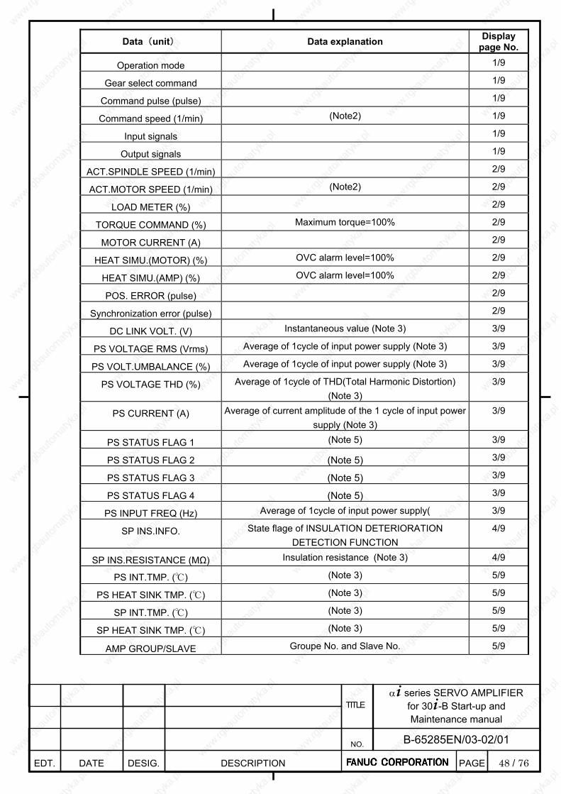
48 / 76
α+ series SERVO AMPLIFIER for 30+-B Start-up and Maintenance manual
EDT. DATE DESIG. DESCRIPTION
B-65285EN/03-02/01 NO.
TITLE
PAGE
Data(unit) Data explanation Display page No.
Operation mode 1/9
Gear select command 1/9
Command pulse (pulse) 1/9
Command speed (1/min) (Note2) 1/9
Input signals 1/9
Output signals 1/9
ACT.SPINDLE SPEED (1/min) 2/9
ACT.MOTOR SPEED (1/min) (Note2) 2/9
LOAD METER (%) 2/9
TORQUE COMMAND (%) Maximum torque=100% 2/9
MOTOR CURRENT (A) 2/9
HEAT SIMU.(MOTOR) (%) OVC alarm level=100% 2/9
HEAT SIMU.(AMP) (%) OVC alarm level=100% 2/9
POS. ERROR (pulse) 2/9
Synchronization error (pulse) 2/9
DC LINK VOLT. (V) Instantaneous value (Note 3) 3/9
PS VOLTAGE RMS (Vrms) Average of 1cycle of input power supply (Note 3) 3/9
PS VOLT.UMBALANCE (%) Average of 1cycle of input power supply (Note 3) 3/9
PS VOLTAGE THD (%) Average of 1cycle of THD(Total Harmonic Distortion) (Note 3)
3/9
PS CURRENT (A) Average of current amplitude of the 1 cycle of input power supply (Note 3)
3/9
PS STATUS FLAG 1 (Note 5) 3/9
PS STATUS FLAG 2 (Note 5) 3/9
PS STATUS FLAG 3 (Note 5) 3/9
PS STATUS FLAG 4 (Note 5) 3/9
PS INPUT FREQ (Hz) Average of 1cycle of input power supply( 3/9
SP INS.INFO. State flage of INSULATION DETERIORATION DETECTION FUNCTION
4/9
SP INS.RESISTANCE (MΩ) Insulation resistance (Note 3) 4/9
PS INT.TMP. () (Note 3) 5/9
PS HEAT SINK TMP. () (Note 3) 5/9
SP INT.TMP. () (Note 3) 5/9
SP HEAT SINK TMP. () (Note 3) 5/9
AMP GROUP/SLAVE Groupe No. and Slave No. 5/9
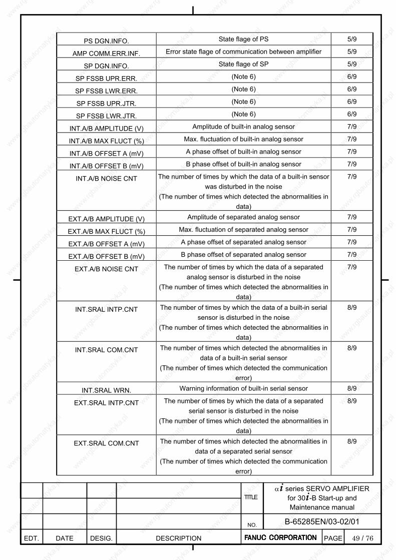
49 / 76
α+ series SERVO AMPLIFIER for 30+-B Start-up and Maintenance manual
EDT. DATE DESIG. DESCRIPTION
B-65285EN/03-02/01 NO.
TITLE
PAGE
PS DGN.INFO. State flage of PS 5/9
AMP COMM.ERR.INF. Error state flage of communication between amplifier 5/9
SP DGN.INFO. State flage of SP 5/9
SP FSSB UPR.ERR. (Note 6) 6/9
SP FSSB LWR.ERR. (Note 6) 6/9
SP FSSB UPR.JTR. (Note 6) 6/9
SP FSSB LWR.JTR. (Note 6) 6/9
INT.A/B AMPLITUDE (V) Amplitude of built-in analog sensor 7/9
INT.A/B MAX FLUCT (%) Max. fluctuation of built-in analog sensor 7/9
INT.A/B OFFSET A (mV) A phase offset of built-in analog sensor 7/9
INT.A/B OFFSET B (mV) B phase offset of built-in analog sensor 7/9
INT.A/B NOISE CNT The number of times by which the data of a built-in sensor was disturbed in the noise
(The number of times which detected the abnormalities in data)
7/9
EXT.A/B AMPLITUDE (V) Amplitude of separated analog sensor 7/9
EXT.A/B MAX FLUCT (%) Max. fluctuation of separated analog sensor 7/9
EXT.A/B OFFSET A (mV) A phase offset of separated analog sensor 7/9
EXT.A/B OFFSET B (mV) B phase offset of separated analog sensor 7/9
EXT.A/B NOISE CNT The number of times by which the data of a separated analog sensor is disturbed in the noise
(The number of times which detected the abnormalities in data)
7/9
INT.SRAL INTP.CNT The number of times by which the data of a built-in serial sensor is disturbed in the noise
(The number of times which detected the abnormalities in data)
8/9
INT.SRAL COM.CNT The number of times which detected the abnormalities in data of a built-in serial sensor
(The number of times which detected the communication error)
8/9
INT.SRAL WRN. Warning information of built-in serial sensor 8/9
EXT.SRAL INTP.CNT The number of times by which the data of a separated serial sensor is disturbed in the noise
(The number of times which detected the abnormalities in data)
8/9
EXT.SRAL COM.CNT The number of times which detected the abnormalities in data of a separated serial sensor
(The number of times which detected the communication error)
8/9
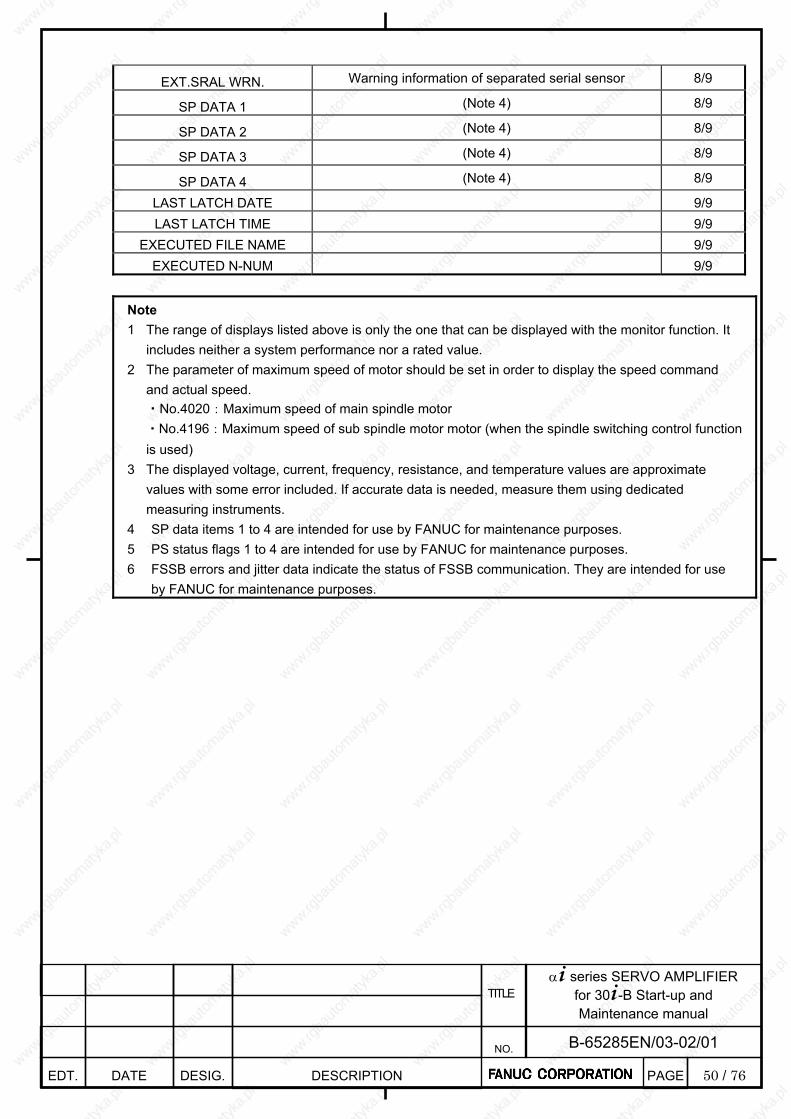
50 / 76
α+ series SERVO AMPLIFIER for 30+-B Start-up and Maintenance manual
EDT. DATE DESIG. DESCRIPTION
B-65285EN/03-02/01 NO.
TITLE
PAGE
EXT.SRAL WRN. Warning information of separated serial sensor 8/9
SP DATA 1 (Note 4) 8/9
SP DATA 2 (Note 4) 8/9
SP DATA 3 (Note 4) 8/9
SP DATA 4 (Note 4) 8/9
LAST LATCH DATE 9/9 LAST LATCH TIME 9/9
EXECUTED FILE NAME 9/9 EXECUTED N-NUM 9/9
Note 1 The range of displays listed above is only the one that can be displayed with the monitor function. It
includes neither a system performance nor a rated value. 2 The parameter of maximum speed of motor should be set in order to display the speed command
and actual speed. ・No.4020:Maximum speed of main spindle motor ・No.4196:Maximum speed of sub spindle motor motor (when the spindle switching control function is used)
3 The displayed voltage, current, frequency, resistance, and temperature values are approximate values with some error included. If accurate data is needed, measure them using dedicated measuring instruments.
4 SP data items 1 to 4 are intended for use by FANUC for maintenance purposes. 5 PS status flags 1 to 4 are intended for use by FANUC for maintenance purposes. 6 FSSB errors and jitter data indicate the status of FSSB communication. They are intended for use
by FANUC for maintenance purposes.
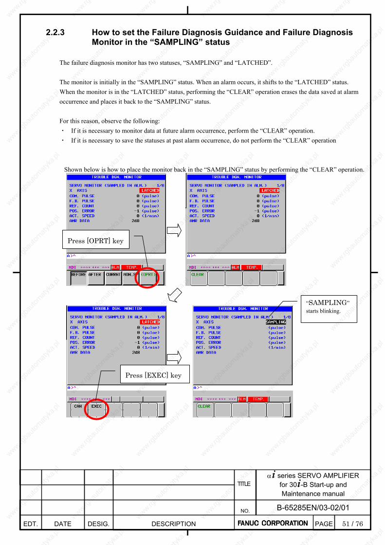
51 / 76
α+ series SERVO AMPLIFIER for 30+-B Start-up and Maintenance manual
EDT. DATE DESIG. DESCRIPTION
B-65285EN/03-02/01 NO.
TITLE
PAGE
2.2.3 How to set the Failure Diagnosis Guidance and Failure Diagnosis
Monitor in the “SAMPLING” status The failure diagnosis monitor has two statuses, “SAMPLING” and “LATCHED”. The monitor is initially in the “SAMPLING” status. When an alarm occurs, it shifts to the “LATCHED” status. When the monitor is in the “LATCHED” status, performing the “CLEAR” operation erases the data saved at alarm occurrence and places it back to the “SAMPLING” status. For this reason, observe the following: ・ If it is necessary to monitor data at future alarm occurrence, perform the “CLEAR” operation. ・ If it is necessary to save the statuses at past alarm occurrence, do not perform the “CLEAR” operation
Shown below is how to place the monitor back in the “SAMPLING” status by performing the “CLEAR” operation.
Press [OPRT] key
“SAMPLING” starts blinking.
Press [EXEC] key
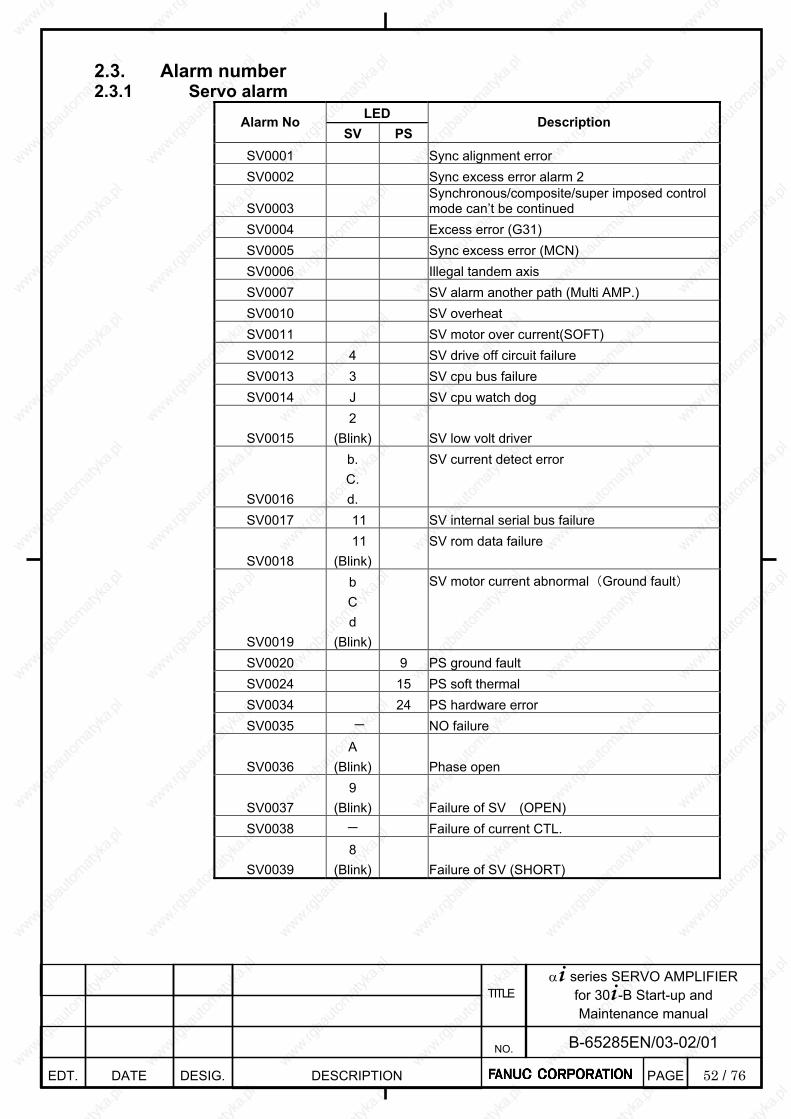
52 / 76
α+ series SERVO AMPLIFIER for 30+-B Start-up and Maintenance manual
EDT. DATE DESIG. DESCRIPTION
B-65285EN/03-02/01 NO.
TITLE
PAGE
2.3. Alarm number 2.3.1 Servo alarm
LED Alarm No SV PS
Description
SV0001 Sync alignment error SV0002 Sync excess error alarm 2
SV0003 Synchronous/composite/super imposed control mode can’t be continued
SV0004 Excess error (G31) SV0005 Sync excess error (MCN) SV0006 Illegal tandem axis SV0007 SV alarm another path (Multi AMP.) SV0010 SV overheat SV0011 SV motor over current(SOFT) SV0012 4 SV drive off circuit failure SV0013 3 SV cpu bus failure SV0014 J SV cpu watch dog
SV0015 2
(Blink) SV low volt driver
SV0016
b. C. d.
SV current detect error
SV0017 11 SV internal serial bus failure
SV0018 11
(Blink)
SV rom data failure
SV0019
b C d
(Blink)
SV motor current abnormal(Ground fault)
SV0020 9 PS ground fault SV0024 15 PS soft thermal SV0034 24 PS hardware error SV0035 - NO failure
SV0036 A
(Blink) Phase open
SV0037 9
(Blink) Failure of SV (OPEN) SV0038 - Failure of current CTL.
SV0039 8
(Blink) Failure of SV (SHORT)
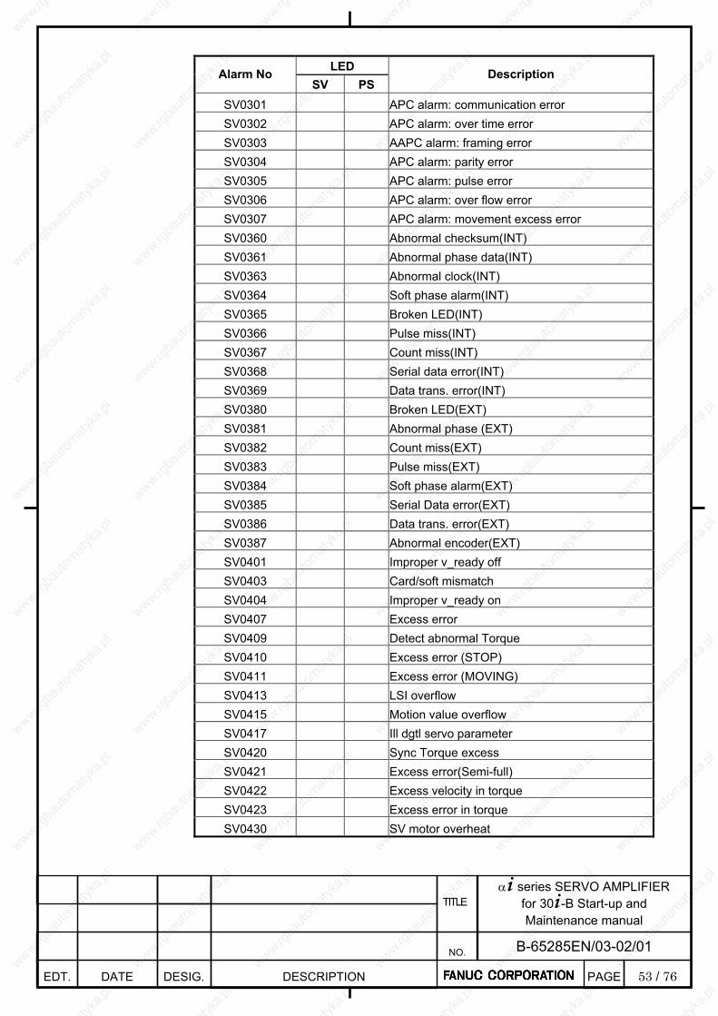
53 / 76
α+ series SERVO AMPLIFIER for 30+-B Start-up and Maintenance manual
EDT. DATE DESIG. DESCRIPTION
B-65285EN/03-02/01 NO.
TITLE
PAGE
LED Alarm No
SV PS Description
SV0301 APC alarm: communication error SV0302 APC alarm: over time error SV0303 AAPC alarm: framing error SV0304 APC alarm: parity error SV0305 APC alarm: pulse error SV0306 APC alarm: over flow error SV0307 APC alarm: movement excess error SV0360 Abnormal checksum(INT) SV0361 Abnormal phase data(INT) SV0363 Abnormal clock(INT) SV0364 Soft phase alarm(INT) SV0365 Broken LED(INT) SV0366 Pulse miss(INT) SV0367 Count miss(INT) SV0368 Serial data error(INT) SV0369 Data trans. error(INT) SV0380 Broken LED(EXT) SV0381 Abnormal phase (EXT) SV0382 Count miss(EXT) SV0383 Pulse miss(EXT) SV0384 Soft phase alarm(EXT) SV0385 Serial Data error(EXT) SV0386 Data trans. error(EXT) SV0387 Abnormal encoder(EXT) SV0401 Improper v_ready off SV0403 Card/soft mismatch SV0404 Improper v_ready on SV0407 Excess error SV0409 Detect abnormal Torque SV0410 Excess error (STOP) SV0411 Excess error (MOVING) SV0413 LSI overflow SV0415 Motion value overflow SV0417 Ill dgtl servo parameter SV0420 Sync Torque excess SV0421 Excess error(Semi-full) SV0422 Excess velocity in torque SV0423 Excess error in torque SV0430 SV motor overheat
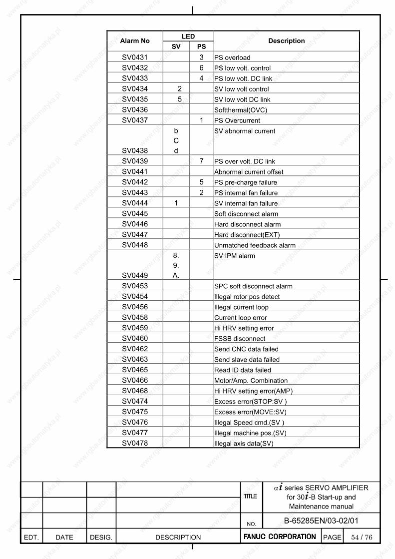
54 / 76
α+ series SERVO AMPLIFIER for 30+-B Start-up and Maintenance manual
EDT. DATE DESIG. DESCRIPTION
B-65285EN/03-02/01 NO.
TITLE
PAGE
LED Alarm No
SV PS Description
SV0431 3 PS overload SV0432 6 PS low volt. control SV0433 4 PS low volt. DC link SV0434 2 SV low volt control SV0435 5 SV low volt DC link SV0436 Softthermal(OVC) SV0437 1 PS Overcurrent
SV0438
b C d
SV abnormal current
SV0439 7 PS over volt. DC link SV0441 Abnormal current offset SV0442 5 PS pre-charge failure SV0443 2 PS internal fan failure SV0444 1 SV internal fan failure SV0445 Soft disconnect alarm SV0446 Hard disconnect alarm SV0447 Hard disconnect(EXT) SV0448 Unmatched feedback alarm
SV0449
8. 9. A.
SV IPM alarm
SV0453 SPC soft disconnect alarm SV0454 Illegal rotor pos detect SV0456 Illegal current loop SV0458 Current loop error SV0459 Hi HRV setting error SV0460 FSSB disconnect SV0462 Send CNC data failed SV0463 Send slave data failed SV0465 Read ID data failed SV0466 Motor/Amp. Combination SV0468 Hi HRV setting error(AMP) SV0474 Excess error(STOP:SV ) SV0475 Excess error(MOVE:SV) SV0476 Illegal Speed cmd.(SV ) SV0477 Illegal machine pos.(SV) SV0478 Illegal axis data(SV)
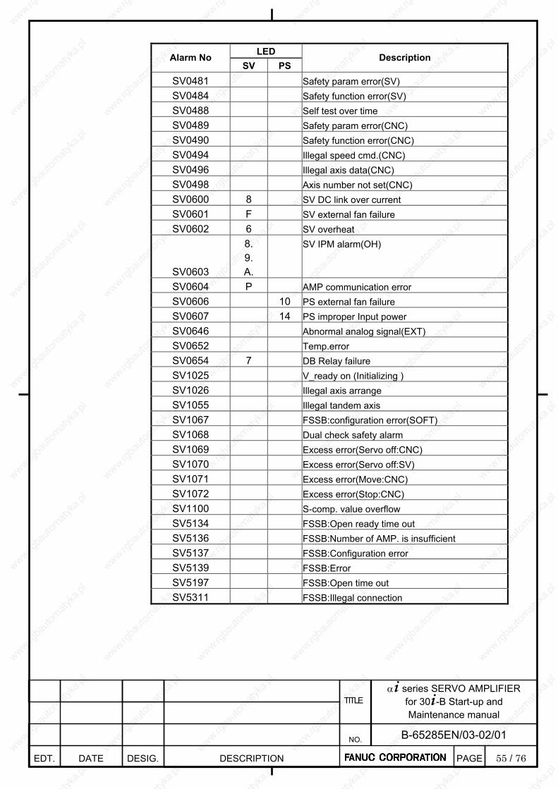
55 / 76
α+ series SERVO AMPLIFIER for 30+-B Start-up and Maintenance manual
EDT. DATE DESIG. DESCRIPTION
B-65285EN/03-02/01 NO.
TITLE
PAGE
LED Alarm No
SV PS Description
SV0481 Safety param error(SV) SV0484 Safety function error(SV) SV0488 Self test over time SV0489 Safety param error(CNC) SV0490 Safety function error(CNC) SV0494 Illegal speed cmd.(CNC) SV0496 Illegal axis data(CNC) SV0498 Axis number not set(CNC) SV0600 8 SV DC link over current SV0601 F SV external fan failure SV0602 6 SV overheat
SV0603
8. 9. A.
SV IPM alarm(OH)
SV0604 P AMP communication error SV0606 10 PS external fan failure SV0607 14 PS improper Input power SV0646 Abnormal analog signal(EXT) SV0652 Temp.error SV0654 7 DB Relay failure SV1025 V_ready on (Initializing ) SV1026 Illegal axis arrange SV1055 Illegal tandem axis SV1067 FSSB:configuration error(SOFT) SV1068 Dual check safety alarm SV1069 Excess error(Servo off:CNC) SV1070 Excess error(Servo off:SV) SV1071 Excess error(Move:CNC) SV1072 Excess error(Stop:CNC) SV1100 S-comp. value overflow SV5134 FSSB:Open ready time out SV5136 FSSB:Number of AMP. is insufficient SV5137 FSSB:Configuration error SV5139 FSSB:Error SV5197 FSSB:Open time out SV5311 FSSB:Illegal connection
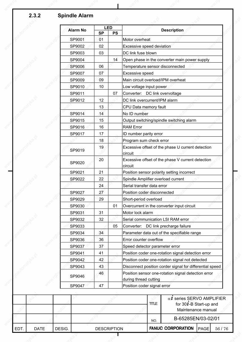
56 / 76
α+ series SERVO AMPLIFIER for 30+-B Start-up and Maintenance manual
EDT. DATE DESIG. DESCRIPTION
B-65285EN/03-02/01 NO.
TITLE
PAGE
2.3.2 Spindle Alarm
LED Alarm No SP PS
Description
SP9001 01 Motor overheat SP9002 02 Excessive speed deviation SP9003 03 DC link fuse blown
SP9004 14 Open phase in the converter main power supply
SP9006 06 Temperature sensor disconnected
SP9007 07 Excessive speed
SP9009 09 Main circuit overload/IPM overheat
SP9010 10 Low voltage input power
SP9011 07 Converter: DC link overvoltage
SP9012 12 DC link overcurrent/IPM alarm 13 CPU Data memory fault
SP9014 14 No ID number SP9015 15 Output switching/spindle switching alarm
SP9016 16 RAM Error
SP9017 17 ID number parity error
18 Program sum check error
SP9019 19 Excessive offset of the phase U current detection
circuit
SP9020 20 Excessive offset of the phase V current detection
circuit SP9021 21 Position sensor polarity setting incorrect
SP9022 22 Spindle Amplifier overload current
24 Serial transfer data error
SP9027 27 Position coder disconnected
SP9029 29 Short-period overload
SP9030 01 Overcurrent in the converter input circuit
SP9031 31 Motor lock alarm
SP9032 32 Serial communication LSI RAM error
SP9033 05 Converter: DC link precharge failure
SP9034 34 Parameter data out of the specifiable range
SP9036 36 Error counter overflow
SP9037 37 Speed detector parameter error
SP9041 41 Position coder one-rotation signal detection error
SP9042 42 Position coder one-rotation signal not detected
SP9043 43 Disconnect position corder signal for differential speed
SP9046 46 Position sensor one-rotation signal detection error
during thread cutting SP9047 47 Position coder signal error
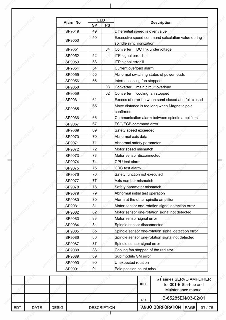
57 / 76
α+ series SERVO AMPLIFIER for 30+-B Start-up and Maintenance manual
EDT. DATE DESIG. DESCRIPTION
B-65285EN/03-02/01 NO.
TITLE
PAGE
LED Alarm No
SP PS Description
SP9049 49 Differential speed is over value
SP9050 50 Excessive speed command calculation value during
spindle synchronization SP9051 04 Converter: DC link undervoltage
SP9052 52 ITP signal error I
SP9053 53 ITP signal error II
SP9054 54 Current overload alarm
SP9055 55 Abnormal switching status of power leads
SP9056 56 Internal cooling fan stopped
SP9058 03 Converter: main circuit overload
SP9059 02 Converter: cooling fan stopped
SP9061 61 Excess of error between semi-closed and full-closed
SP9065 65 Move distance is too long when Magnetic pole
confirmed SP9066 66 Communication alarm between spindle amplifiers
SP9067 67 FSC/EGB command error
SP9069 69 Safety speed exceeded
SP9070 70 Abnormal axis data
SP9071 71 Abnormal safety parameter
SP9072 72 Motor speed mismatch
SP9073 73 Motor sensor disconnected
SP9074 74 CPU test alarm
SP9075 75 CRC test alarm
SP9076 76 Safety function not executed
SP9077 77 Axis number mismatch
SP9078 78 Safety parameter mismatch
SP9079 79 Abnormal initial test operation
SP9080 80 Alarm at the other spindle amplifier
SP9081 81 Motor sensor one-rotation signal detection error
SP9082 82 Motor sensor one-rotation signal not detected
SP9083 83 Motor sensor signal error
SP9084 84 Spindle sensor disconnected
SP9085 85 Spindle sensor one-rotation signal detection error
SP9086 86 Spindle sensor one-rotation signal not detected
SP9087 87 Spindle sensor signal error
SP9088 88 Cooling fan stopped of the radiator
SP9089 89 Sub module SM error
SP9090 90 Unexpected rotation
SP9091 91 Pole position count miss
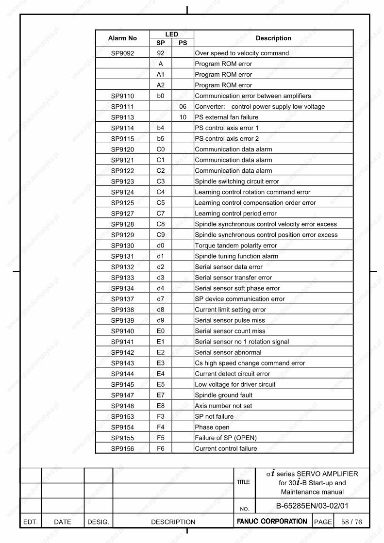
58 / 76
α+ series SERVO AMPLIFIER for 30+-B Start-up and Maintenance manual
EDT. DATE DESIG. DESCRIPTION
B-65285EN/03-02/01 NO.
TITLE
PAGE
LED Alarm No
SP PS Description
SP9092 92 Over speed to velocity command
A Program ROM error
A1 Program ROM error
A2 Program ROM error
SP9110 b0 Communication error between amplifiers
SP9111 06 Converter: control power supply low voltage
SP9113 10 PS external fan failure
SP9114 b4 PS control axis error 1
SP9115 b5 PS control axis error 2
SP9120 C0 Communication data alarm
SP9121 C1 Communication data alarm
SP9122 C2 Communication data alarm
SP9123 C3 Spindle switching circuit error
SP9124 C4 Learning control rotation command error
SP9125 C5 Learning control compensation order error
SP9127 C7 Learning control period error
SP9128 C8 Spindle synchronous control velocity error excess
SP9129 C9 Spindle synchronous control position error excess
SP9130 d0 Torque tandem polarity error
SP9131 d1 Spindle tuning function alarm
SP9132 d2 Serial sensor data error
SP9133 d3 Serial sensor transfer error
SP9134 d4 Serial sensor soft phase error
SP9137 d7 SP device communication error
SP9138 d8 Current limit setting error
SP9139 d9 Serial sensor pulse miss
SP9140 E0 Serial sensor count miss
SP9141 E1 Serial sensor no 1 rotation signal
SP9142 E2 Serial sensor abnormal
SP9143 E3 Cs high speed change command error
SP9144 E4 Current detect circuit error
SP9145 E5 Low voltage for driver circuit
SP9147 E7 Spindle ground fault
SP9148 E8 Axis number not set
SP9153 F3 SP not failure
SP9154 F4 Phase open
SP9155 F5 Failure of SP (OPEN)
SP9156 F6 Current control failure
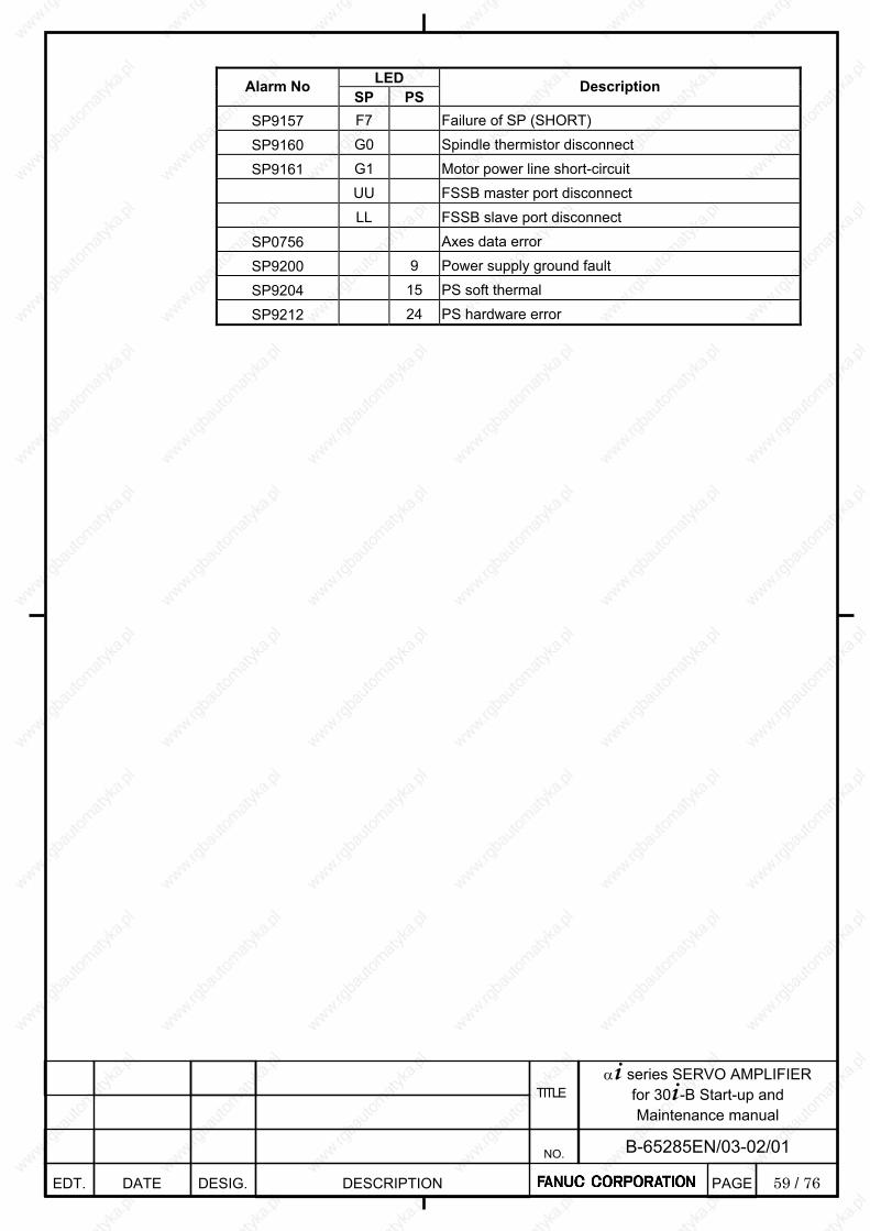
59 / 76
α+ series SERVO AMPLIFIER for 30+-B Start-up and Maintenance manual
EDT. DATE DESIG. DESCRIPTION
B-65285EN/03-02/01 NO.
TITLE
PAGE
LED Alarm No
SP PS Description
SP9157 F7 Failure of SP (SHORT)
SP9160 G0 Spindle thermistor disconnect
SP9161 G1 Motor power line short-circuit
UU FSSB master port disconnect
LL FSSB slave port disconnect
SP0756 Axes data error
SP9200 9 Power supply ground fault
SP9204 15 PS soft thermal
SP9212 24 PS hardware error
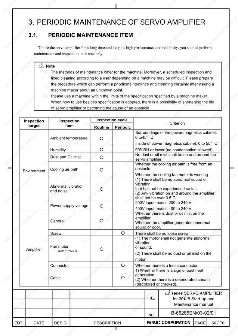
60 / 76
α+ series SERVO AMPLIFIER for 30+-B Start-up and Maintenance manual
EDT. DATE DESIG. DESCRIPTION
B-65285EN/03-02/01 NO.
TITLE
PAGE
3. PERIODIC MAINTENANCE OF SERVO AMPLIFIER
3.1. PERIODIC MAINTENANCE ITEM
To use the servo amplifier for a long time and keep its high performance and reliability, you should perform maintenance and inspection on it routinely.
Note ・ The methods of maintenance differ for the machine. Moreover, a scheduled inspection and
fixed cleaning according to a user depending on a machine may be difficult. Please prepare the procedure which can perform a priodicmaintenance and cleaning certainly after asking a machine maker about an unknown point.
・ Please use a machine within the limits of the specification specified by a machine maker. When how to use besides specification is adopted, there is a possibility of shortening the life of servo amplifier or becoming the cause of an obstacle
Inspection cycle Inspection
target Inspection
item Routine PeriodicCriterion
Ambient temperature Surroundings of the power magnetics cabinet: 0 to45°C Inside of power magnetics cabinet: 0 to 55°C
Humidity 90%RH or lower (no condensation allowed)
Dust and Oil mist No dust or oil mist shall be on and around the servo amplifier.
Cooling air path Whether the cooling air path is free from an obstacle. Whether the cooling fan motor is working.
Abnormal vibration and noise
(1) There shall be no abnormal sound or vibration that has not be experienced so far. (2) Any vibration on and around the amplifier shall not be over 0.5 G.
Environment
Power supply voltage 200V input model: 200 to 240 V. 400V input model: 400 to 240 V.
General
Whether there is dust or oil mist on the amplifier. Whether the amplifier generates abnormal sound or odor.
Screw There shall be no loose screw
Fan motor (note 1) (note 2)
(1) The motor shall not generate abnormal vibration or sound. (2) There shall be no dust or oil mist on the motor.
Connector Whether there is a loose connector.
Amplifier
Cable
1) Whether there is a sign of past heat generation. (2) Whether there is a deteriorated sheath (discolored or cracked).
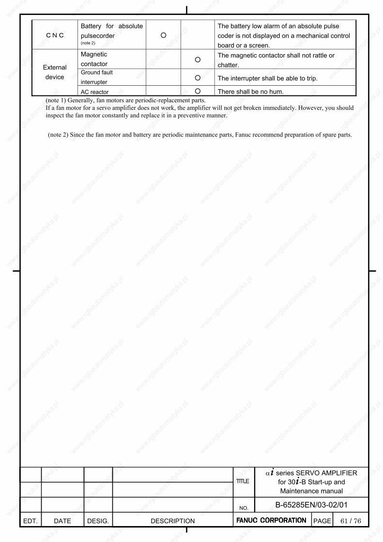
61 / 76
α+ series SERVO AMPLIFIER for 30+-B Start-up and Maintenance manual
EDT. DATE DESIG. DESCRIPTION
B-65285EN/03-02/01 NO.
TITLE
PAGE
CNC Battery for absolute pulsecorder
(note 2)
The battery low alarm of an absolute pulse coder is not displayed on a mechanical control board or a screen.
Magnetic contactor
The magnetic contactor shall not rattle or chatter.
Ground fault
interrupter The interrupter shall be able to trip.
External device
AC reactor There shall be no hum. (note 1) Generally, fan motors are periodic-replacement parts. If a fan motor for a servo amplifier does not work, the amplifier will not get broken immediately. However, you should inspect the fan motor constantly and replace it in a preventive manner. (note 2) Since the fan motor and battery are periodic maintenance parts, Fanuc recommend preparation of spare parts.
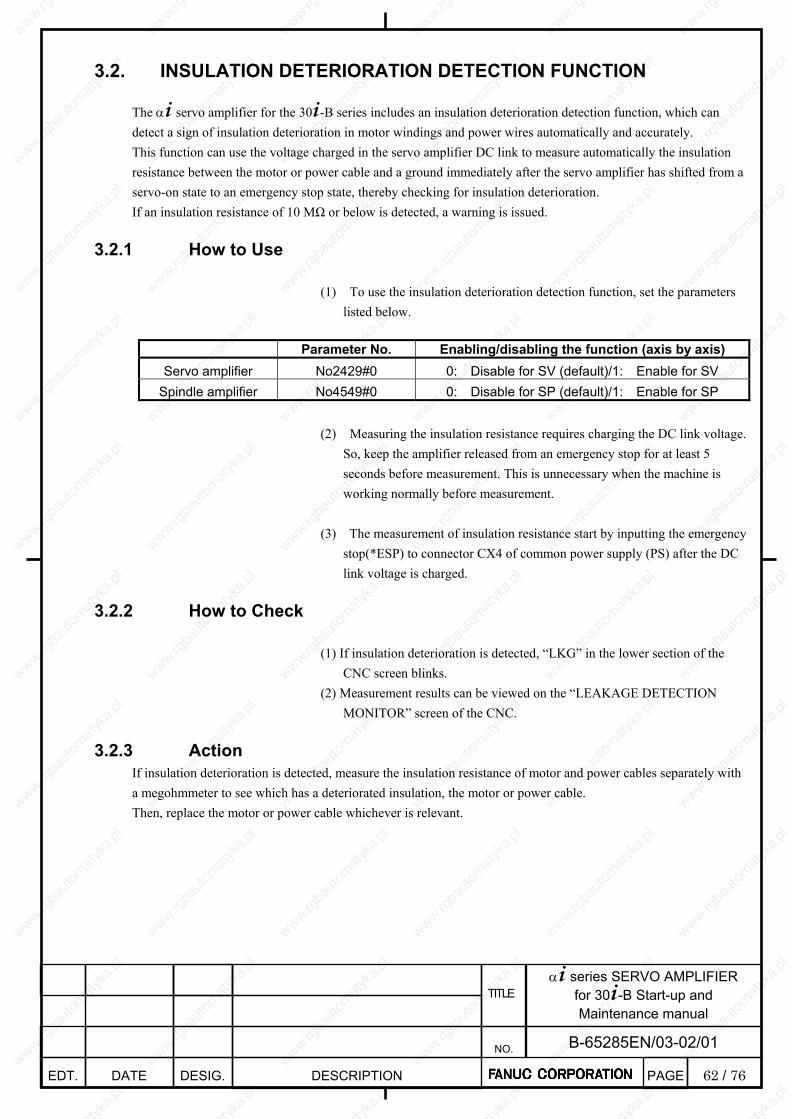
62 / 76
α+ series SERVO AMPLIFIER for 30+-B Start-up and Maintenance manual
EDT. DATE DESIG. DESCRIPTION
B-65285EN/03-02/01 NO.
TITLE
PAGE
3.2. INSULATION DETERIORATION DETECTION FUNCTION
The α+ servo amplifier for the 30+-B series includes an insulation deterioration detection function, which can detect a sign of insulation deterioration in motor windings and power wires automatically and accurately. This function can use the voltage charged in the servo amplifier DC link to measure automatically the insulation resistance between the motor or power cable and a ground immediately after the servo amplifier has shifted from a servo-on state to an emergency stop state, thereby checking for insulation deterioration. If an insulation resistance of 10 MΩ or below is detected, a warning is issued.
3.2.1 How to Use (1) To use the insulation deterioration detection function, set the parameters
listed below.
Parameter No. Enabling/disabling the function (axis by axis) Servo amplifier No2429#0 0: Disable for SV (default)/1: Enable for SV
Spindle amplifier No4549#0 0: Disable for SP (default)/1: Enable for SP
(2) Measuring the insulation resistance requires charging the DC link voltage. So, keep the amplifier released from an emergency stop for at least 5 seconds before measurement. This is unnecessary when the machine is working normally before measurement.
(3) The measurement of insulation resistance start by inputting the emergency
stop(*ESP) to connector CX4 of common power supply (PS) after the DC link voltage is charged.
3.2.2 How to Check
(1) If insulation deterioration is detected, “LKG” in the lower section of the
CNC screen blinks. (2) Measurement results can be viewed on the “LEAKAGE DETECTION
MONITOR” screen of the CNC.
3.2.3 Action If insulation deterioration is detected, measure the insulation resistance of motor and power cables separately with a megohmmeter to see which has a deteriorated insulation, the motor or power cable. Then, replace the motor or power cable whichever is relevant.
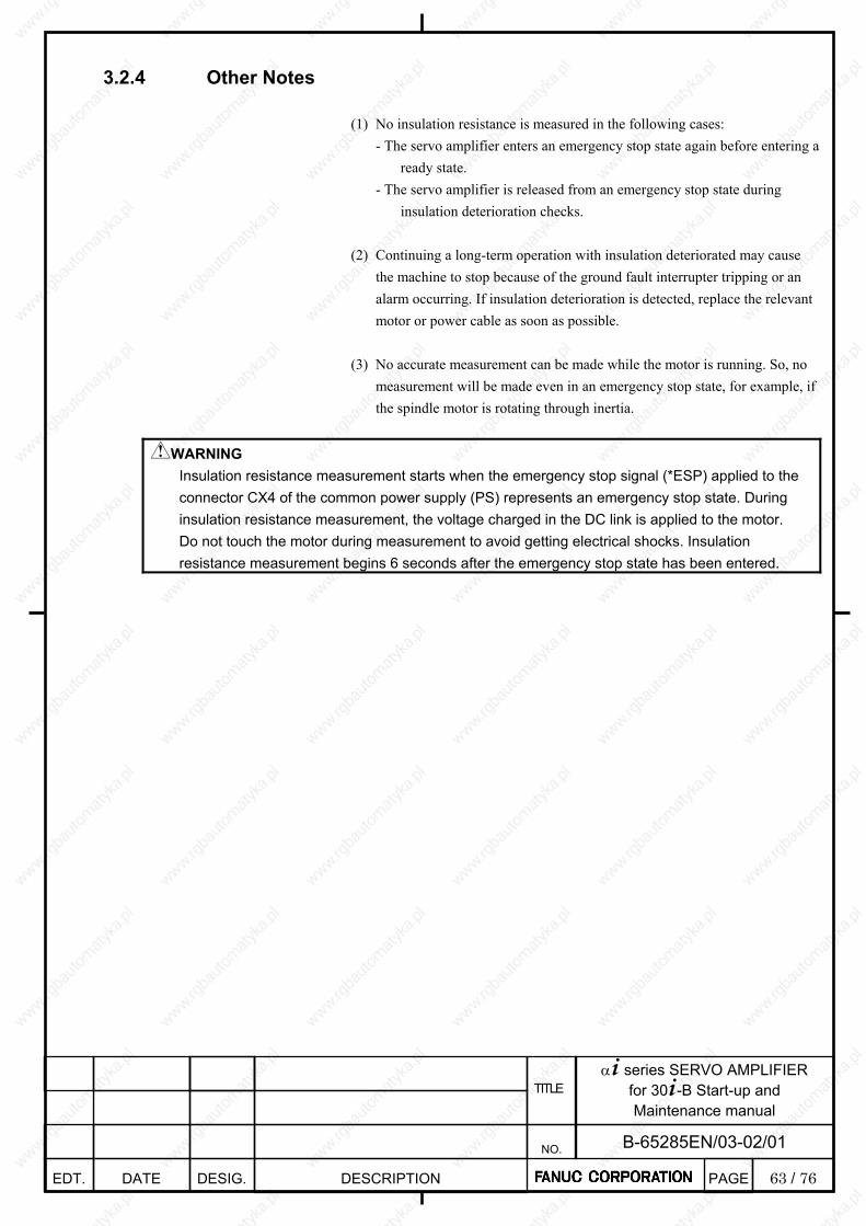
63 / 76
α+ series SERVO AMPLIFIER for 30+-B Start-up and Maintenance manual
EDT. DATE DESIG. DESCRIPTION
B-65285EN/03-02/01 NO.
TITLE
PAGE
3.2.4 Other Notes
(1) No insulation resistance is measured in the following cases:
- The servo amplifier enters an emergency stop state again before entering a ready state.
- The servo amplifier is released from an emergency stop state during insulation deterioration checks.
(2) Continuing a long-term operation with insulation deteriorated may cause
the machine to stop because of the ground fault interrupter tripping or an alarm occurring. If insulation deterioration is detected, replace the relevant motor or power cable as soon as possible.
(3) No accurate measurement can be made while the motor is running. So, no
measurement will be made even in an emergency stop state, for example, if the spindle motor is rotating through inertia.
WARNING Insulation resistance measurement starts when the emergency stop signal (*ESP) applied to the connector CX4 of the common power supply (PS) represents an emergency stop state. During insulation resistance measurement, the voltage charged in the DC link is applied to the motor. Do not touch the motor during measurement to avoid getting electrical shocks. Insulation resistance measurement begins 6 seconds after the emergency stop state has been entered.
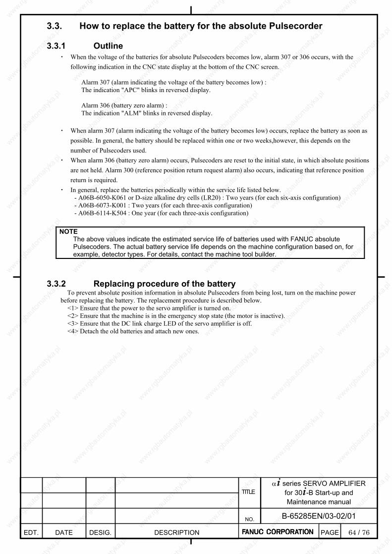
64 / 76
α+ series SERVO AMPLIFIER for 30+-B Start-up and Maintenance manual
EDT. DATE DESIG. DESCRIPTION
B-65285EN/03-02/01 NO.
TITLE
PAGE
3.3. How to replace the battery for the absolute Pulsecorder
3.3.1 Outline ・ When the voltage of the batteries for absolute Pulsecoders becomes low, alarm 307 or 306 occurs, with the
following indication in the CNC state display at the bottom of the CNC screen.
Alarm 307 (alarm indicating the voltage of the battery becomes low) : The indication "APC" blinks in reversed display. Alarm 306 (battery zero alarm) : The indication "ALM" blinks in reversed display.
・ When alarm 307 (alarm indicating the voltage of the battery becomes low) occurs, replace the battery as soon as possible. In general, the battery should be replaced within one or two weeks,however, this depends on the number of Pulsecoders used.
・ When alarm 306 (battery zero alarm) occurs, Pulsecoders are reset to the initial state, in which absolute positions are not held. Alarm 300 (reference position return request alarm) also occurs, indicating that reference position return is required.
・ In general, replace the batteries periodically within the service life listed below. - A06B-6050-K061 or D-size alkaline dry cells (LR20) : Two years (for each six-axis configuration) - A06B-6073-K001 : Two years (for each three-axis configuration) - A06B-6114-K504 : One year (for each three-axis configuration)
NOTE
The above values indicate the estimated service life of batteries used with FANUC absolute Pulsecoders. The actual battery service life depends on the machine configuration based on, for example, detector types. For details, contact the machine tool builder.
3.3.2 Replacing procedure of the battery To prevent absolute position information in absolute Pulsecoders from being lost, turn on the machine power
before replacing the battery. The replacement procedure is described below. <1> Ensure that the power to the servo amplifier is turned on. <2> Ensure that the machine is in the emergency stop state (the motor is inactive). <3> Ensure that the DC link charge LED of the servo amplifier is off. <4> Detach the old batteries and attach new ones.
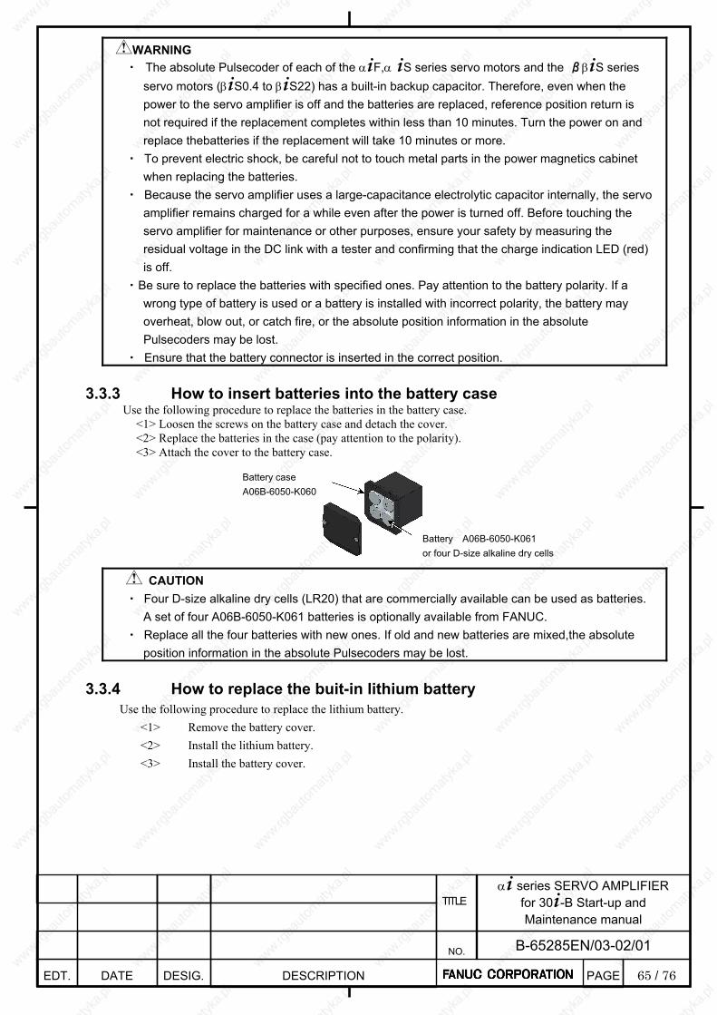
65 / 76
α+ series SERVO AMPLIFIER for 30+-B Start-up and Maintenance manual
EDT. DATE DESIG. DESCRIPTION
B-65285EN/03-02/01 NO.
TITLE
PAGE
WARNING ・ The absolute Pulsecoder of each of the α+F,α +S series servo motors and the ββ+S series
servo motors (β+S0.4 to β+S22) has a built-in backup capacitor. Therefore, even when the power to the servo amplifier is off and the batteries are replaced, reference position return is not required if the replacement completes within less than 10 minutes. Turn the power on and replace thebatteries if the replacement will take 10 minutes or more.
・ To prevent electric shock, be careful not to touch metal parts in the power magnetics cabinet when replacing the batteries.
・ Because the servo amplifier uses a large-capacitance electrolytic capacitor internally, the servo amplifier remains charged for a while even after the power is turned off. Before touching the servo amplifier for maintenance or other purposes, ensure your safety by measuring the residual voltage in the DC link with a tester and confirming that the charge indication LED (red) is off.
・ Be sure to replace the batteries with specified ones. Pay attention to the battery polarity. If a wrong type of battery is used or a battery is installed with incorrect polarity, the battery may overheat, blow out, or catch fire, or the absolute position information in the absolute Pulsecoders may be lost.
・ Ensure that the battery connector is inserted in the correct position. 3.3.3 How to insert batteries into the battery case
Use the following procedure to replace the batteries in the battery case. <1> Loosen the screws on the battery case and detach the cover. <2> Replace the batteries in the case (pay attention to the polarity). <3> Attach the cover to the battery case.
CAUTION ・ Four D-size alkaline dry cells (LR20) that are commercially available can be used as batteries.
A set of four A06B-6050-K061 batteries is optionally available from FANUC. ・ Replace all the four batteries with new ones. If old and new batteries are mixed,the absolute
position information in the absolute Pulsecoders may be lost. 3.3.4 How to replace the buit-in lithium battery
Use the following procedure to replace the lithium battery. <1> Remove the battery cover. <2> Install the lithium battery. <3> Install the battery cover.
Battery case A06B-6050-K060
Battery A06B-6050-K061 or four D-size alkaline dry cells
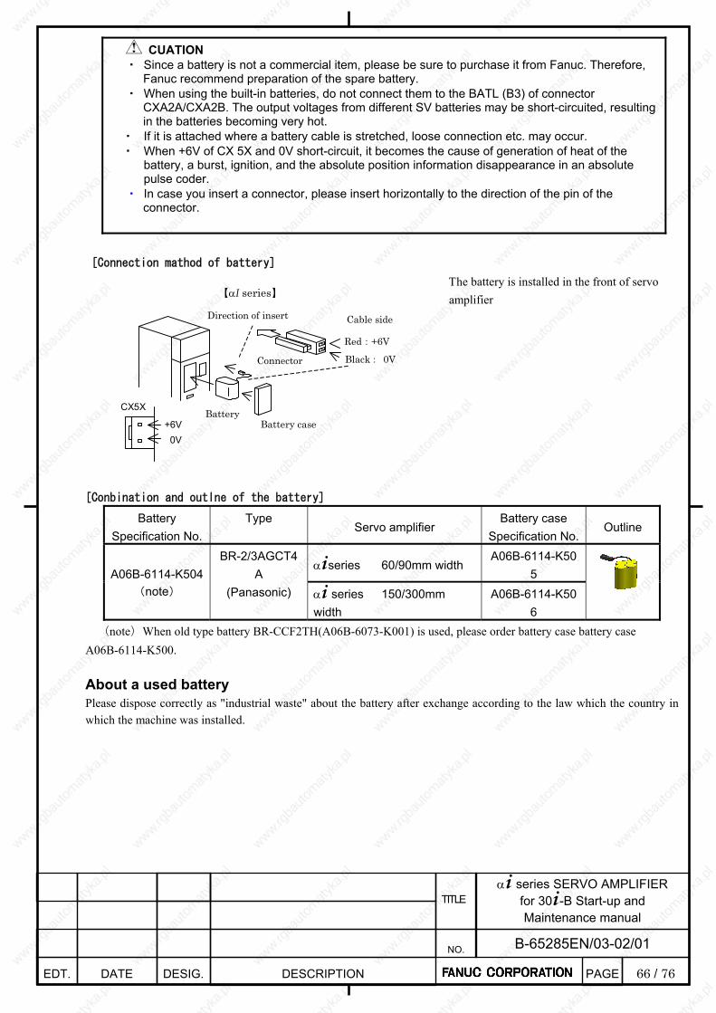
66 / 76
α+ series SERVO AMPLIFIER for 30+-B Start-up and Maintenance manual
EDT. DATE DESIG. DESCRIPTION
B-65285EN/03-02/01 NO.
TITLE
PAGE
CUATION ・ Since a battery is not a commercial item, please be sure to purchase it from Fanuc. Therefore,
Fanuc recommend preparation of the spare battery. ・ When using the built-in batteries, do not connect them to the BATL (B3) of connector
CXA2A/CXA2B. The output voltages from different SV batteries may be short-circuited, resulting in the batteries becoming very hot.
・ If it is attached where a battery cable is stretched, loose connection etc. may occur. ・ When +6V of CX 5X and 0V short-circuit, it becomes the cause of generation of heat of the
battery, a burst, ignition, and the absolute position information disappearance in an absolute pulse coder.
・ In case you insert a connector, please insert horizontally to the direction of the pin of the connector.
[Connection mathod of battery]
Τhe battery is installed in the front of servo amplifier
[Conbination and outlne of the battery]
Battery Specification No.
Type Servo amplifier
Battery case Specification No.
Outline
α+series 60/90mm width A06B-6114-K50
5 A06B-6114-K504 (note)
BR-2/3AGCT4A
(Panasonic) α+ series 150/300mm width
A06B-6114-K506
(note)When old type battery BR-CCF2TH(A06B-6073-K001) is used, please order battery case battery case A06B-6114-K500.
About a used battery Please dispose correctly as "industrial waste" about the battery after exchange according to the law which the country in which the machine was installed.
【αI series】
Battery Battery case
Direction of insert
Red:+6V
Black: 0VConnector
Cable side
CX5X
+6V 0V
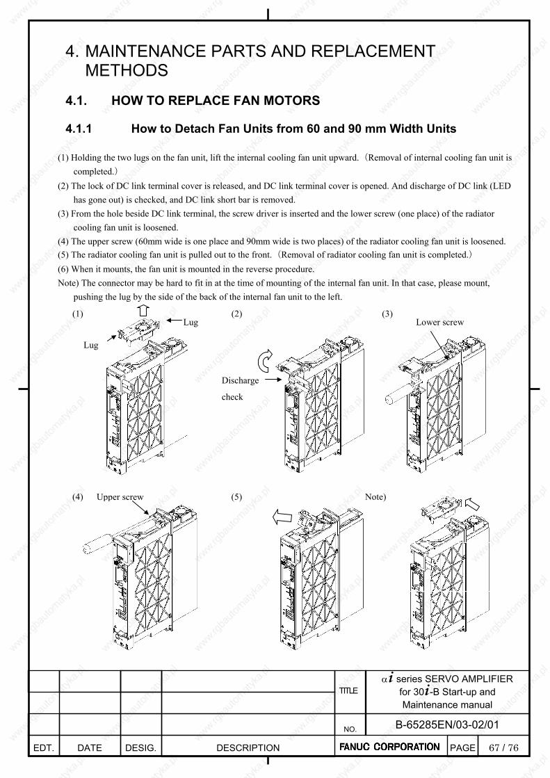
67 / 76
α+ series SERVO AMPLIFIER for 30+-B Start-up and Maintenance manual
EDT. DATE DESIG. DESCRIPTION
B-65285EN/03-02/01 NO.
TITLE
PAGE
4. MAINTENANCE PARTS AND REPLACEMENT METHODS
4.1. HOW TO REPLACE FAN MOTORS
4.1.1 How to Detach Fan Units from 60 and 90 mm Width Units
(1) Holding the two lugs on the fan unit, lift the internal cooling fan unit upward.(Removal of internal cooling fan unit is completed.)
(2) The lock of DC link terminal cover is released, and DC link terminal cover is opened. And discharge of DC link (LED has gone out) is checked, and DC link short bar is removed.
(3) From the hole beside DC link terminal, the screw driver is inserted and the lower screw (one place) of the radiator cooling fan unit is loosened.
(4) The upper screw (60mm wide is one place and 90mm wide is two places) of the radiator cooling fan unit is loosened. (5) The radiator cooling fan unit is pulled out to the front.(Removal of radiator cooling fan unit is completed.) (6) When it mounts, the fan unit is mounted in the reverse procedure. Note) The connector may be hard to fit in at the time of mounting of the internal fan unit. In that case, please mount,
pushing the lug by the side of the back of the internal fan unit to the left.
Lug
Lug
(1) (3) (2)
Upper screw (4) (5) Note)
Discharge
check
Lower screw

68 / 76
α+ series SERVO AMPLIFIER for 30+-B Start-up and Maintenance manual
EDT. DATE DESIG. DESCRIPTION
B-65285EN/03-02/01 NO.
TITLE
PAGE
4.1.2 How to Detach Fan Units from 150 and 300 mm Width Units (1) Holding the two lugs on the fan unit, lift the internal cooling fan unit upward.(Removal of internal cooling fan unit is
completed.) (2) The lock of DC link terminal cover is released, and DC link terminal cover is opened. And discharge (LED has gone
out) of DC link is checked, and DC link short bar is removed. (3) From the hole beside DC link terminal, the screw driver is inserted and the lower screw (one place) of the radiator
cooling fan unit is loosened. (4) The upper screw (one place) of the radiator cooling fan unit is loosened. (5) The radiator cooling fan unit is pulled out to the front.(Removal of radiator cooling fan unit is completed.) (6) When it mounts, the fan unit is mounted in the reverse procedure.
Discharge
check
Lug Lug
(1) (3) (2)
Lower screw
Upper screw (4) (5)
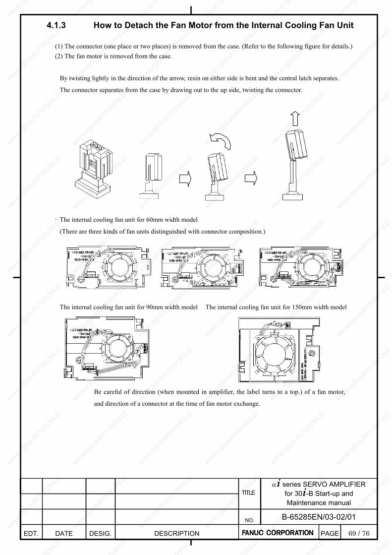
69 / 76
α+ series SERVO AMPLIFIER for 30+-B Start-up and Maintenance manual
EDT. DATE DESIG. DESCRIPTION
B-65285EN/03-02/01 NO.
TITLE
PAGE
4.1.3 How to Detach the Fan Motor from the Internal Cooling Fan Unit
(1) The connector (one place or two places) is removed from the case. (Refer to the following figure for details.) (2) The fan motor is removed from the case. By twisting lightly in the direction of the arrow, resin on either side is bent and the central latch separates.
The connector separates from the case by drawing out to the up side, twisting the connector.
. The internal cooling fan unit for 60mm width model
(There are three kinds of fan units distinguished with connector composition.)
The internal cooling fan unit for 90mm width model
Be careful of direction (when mounted in amplifier, the label turns to a top.) of a fan motor,
and direction of a connector at the time of fan motor exchange.
The internal cooling fan unit for 150mm width model
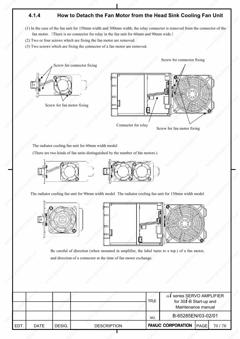
70 / 76
α+ series SERVO AMPLIFIER for 30+-B Start-up and Maintenance manual
EDT. DATE DESIG. DESCRIPTION
B-65285EN/03-02/01 NO.
TITLE
PAGE
4.1.4 How to Detach the Fan Motor from the Head Sink Cooling Fan Unit
(1) In the case of the fan unit for 150mm width and 300mm width, the relay connector is removed from the connector of the fan motor.(There is no connector for relay in the fan unit for 60mm and 90mm wide.)
(2) Two or four screws which are fixing the fan motor are removed. (3) Two screws which are fixing the connector of a fan motor are removed.
Screw for connector fixing
Screw for fan motor fixing
Connector for relay
Screw for connector fixing
Screw for fan motor fixing
The radiator cooling fan unit for 60mm width model
(There are two kinds of fan units distinguished by the number of fan motors.)
The radiator cooling fan unit for 90mm width model The radiator cooling fan unit for 150mm width model
Be careful of direction (when mounted in amplifier, the label turns to a top.) of a fan motor,
and direction of a connector at the time of fan motor exchange.
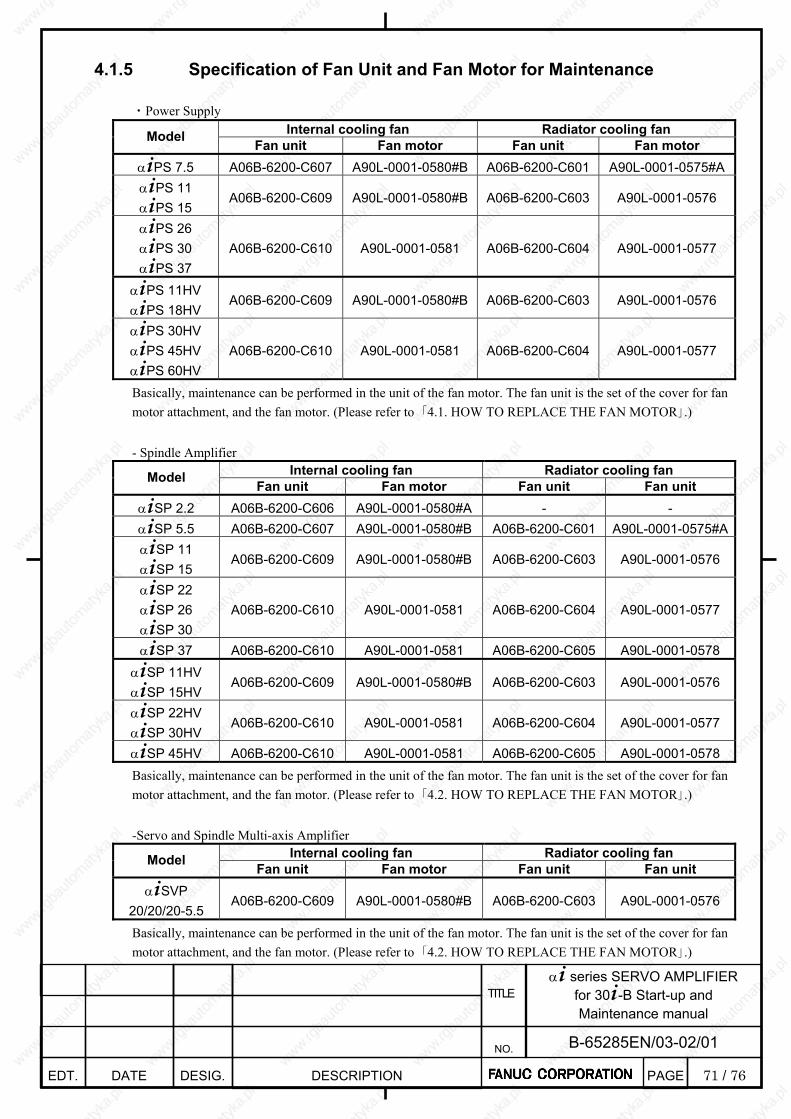
71 / 76
α+ series SERVO AMPLIFIER for 30+-B Start-up and Maintenance manual
EDT. DATE DESIG. DESCRIPTION
B-65285EN/03-02/01 NO.
TITLE
PAGE
4.1.5 Specification of Fan Unit and Fan Motor for Maintenance ・Power Supply
Internal cooling fan Radiator cooling fan Model Fan unit Fan motor Fan unit Fan motor α+PS 7.5 A06B-6200-C607 A90L-0001-0580#B A06B-6200-C601 A90L-0001-0575#Aα+PS 11 α+PS 15
A06B-6200-C609 A90L-0001-0580#B A06B-6200-C603 A90L-0001-0576
α+PS 26 α+PS 30 α+PS 37
A06B-6200-C610 A90L-0001-0581 A06B-6200-C604 A90L-0001-0577
α+PS 11HV α+PS 18HV
A06B-6200-C609 A90L-0001-0580#B A06B-6200-C603 A90L-0001-0576
α+PS 30HV α+PS 45HV α+PS 60HV
A06B-6200-C610 A90L-0001-0581 A06B-6200-C604 A90L-0001-0577
Basically, maintenance can be performed in the unit of the fan motor. The fan unit is the set of the cover for fan motor attachment, and the fan motor. (Please refer to 「4.1. HOW TO REPLACE THE FAN MOTOR」.) - Spindle Amplifier
Internal cooling fan Radiator cooling fan Model Fan unit Fan motor Fan unit Fan unit α+SP 2.2 A06B-6200-C606 A90L-0001-0580#A - - α+SP 5.5 A06B-6200-C607 A90L-0001-0580#B A06B-6200-C601 A90L-0001-0575#Aα+SP 11 α+SP 15
A06B-6200-C609 A90L-0001-0580#B A06B-6200-C603 A90L-0001-0576
α+SP 22 α+SP 26 α+SP 30
A06B-6200-C610 A90L-0001-0581 A06B-6200-C604 A90L-0001-0577
α+SP 37 A06B-6200-C610 A90L-0001-0581 A06B-6200-C605 A90L-0001-0578 α+SP 11HV α+SP 15HV
A06B-6200-C609 A90L-0001-0580#B A06B-6200-C603 A90L-0001-0576
α+SP 22HV α+SP 30HV
A06B-6200-C610 A90L-0001-0581 A06B-6200-C604 A90L-0001-0577
α+SP 45HV A06B-6200-C610 A90L-0001-0581 A06B-6200-C605 A90L-0001-0578 Basically, maintenance can be performed in the unit of the fan motor. The fan unit is the set of the cover for fan motor attachment, and the fan motor. (Please refer to 「4.2. HOW TO REPLACE THE FAN MOTOR」.) -Servo and Spindle Multi-axis Amplifier
Internal cooling fan Radiator cooling fan Model Fan unit Fan motor Fan unit Fan unit α+SVP
20/20/20-5.5 A06B-6200-C609 A90L-0001-0580#B A06B-6200-C603 A90L-0001-0576
Basically, maintenance can be performed in the unit of the fan motor. The fan unit is the set of the cover for fan motor attachment, and the fan motor. (Please refer to 「4.2. HOW TO REPLACE THE FAN MOTOR」.)
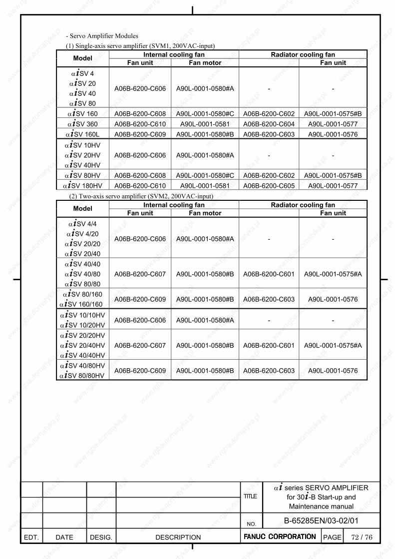
72 / 76
α+ series SERVO AMPLIFIER for 30+-B Start-up and Maintenance manual
EDT. DATE DESIG. DESCRIPTION
B-65285EN/03-02/01 NO.
TITLE
PAGE
- Servo Amplifier Modules (1) Single-axis servo amplifier (SVM1, 200VAC-input)
Internal cooling fan Radiator cooling fan Model Fan unit Fan motor Fan unit α+SV 4
α+SV 20 α+SV 40 α+SV 80
A06B-6200-C606 A90L-0001-0580#A - -
α+SV 160 A06B-6200-C608 A90L-0001-0580#C A06B-6200-C602 A90L-0001-0575#Bα+SV 360 A06B-6200-C610 A90L-0001-0581 A06B-6200-C604 A90L-0001-0577
α+SV 160L A06B-6200-C609 A90L-0001-0580#B A06B-6200-C603 A90L-0001-0576 α+SV 10HV α+SV 20HV α+SV 40HV
A06B-6200-C606 A90L-0001-0580#A - -
α+SV 80HV A06B-6200-C608 A90L-0001-0580#C A06B-6200-C602 A90L-0001-0575#Bα+SV 180HV A06B-6200-C610 A90L-0001-0581 A06B-6200-C605 A90L-0001-0577 (2) Two-axis servo amplifier (SVM2, 200VAC-input)
Internal cooling fan Radiator cooling fan Model Fan unit Fan motor Fan unit α+SV 4/4
α+SV 4/20 α+SV 20/20 α+SV 20/40
A06B-6200-C606 A90L-0001-0580#A - -
α+SV 40/40 α+SV 40/80 α+SV 80/80
A06B-6200-C607 A90L-0001-0580#B A06B-6200-C601 A90L-0001-0575#A
α+SV 80/160 α+SV 160/160
A06B-6200-C609 A90L-0001-0580#B A06B-6200-C603 A90L-0001-0576
α+SV 10/10HV α+SV 10/20HV
A06B-6200-C606 A90L-0001-0580#A - -
α+SV 20/20HV α+SV 20/40HV α+SV 40/40HV
A06B-6200-C607 A90L-0001-0580#B A06B-6200-C601 A90L-0001-0575#A
α+SV 40/80HV α+SV 80/80HV
A06B-6200-C609 A90L-0001-0580#B A06B-6200-C603 A90L-0001-0576

73 / 76
α+ series SERVO AMPLIFIER for 30+-B Start-up and Maintenance manual
EDT. DATE DESIG. DESCRIPTION
B-65285EN/03-02/01 NO.
TITLE
PAGE
(3) Three-axis servo amplifier (SVM3, 200VAC-input) Internal cooling fan Radiator cooling fan Model Fan unit Fan motor Fan unit
α+SV 4/4/4 α+SV 20/20/20 α+SV 20/20/40
A06B-6200-C606 A90L-0001-0580#A - -
α+SV 40/40/40 A06B-6200-C608 A90L-0001-0580#C A06B-6200-C602 A90L-0001-0575#B
α+SV 10/10/10HV α+SV 10/10/20HV
A06B-6200-C606 A90L-0001-0580#A - -
α+SV 20/20/20HV A06B-6200-C608 A90L-0001-0580#C A06B-6200-C602 A90L-0001-0575#B Basically, maintenance can be performed in the unit of the fan motor. The fan unit is the set of the cover for fan motor attachment, and the fan motor. (Please refer to 「4.2. HOW TO REPLACE THE FAN MOTOR」.)
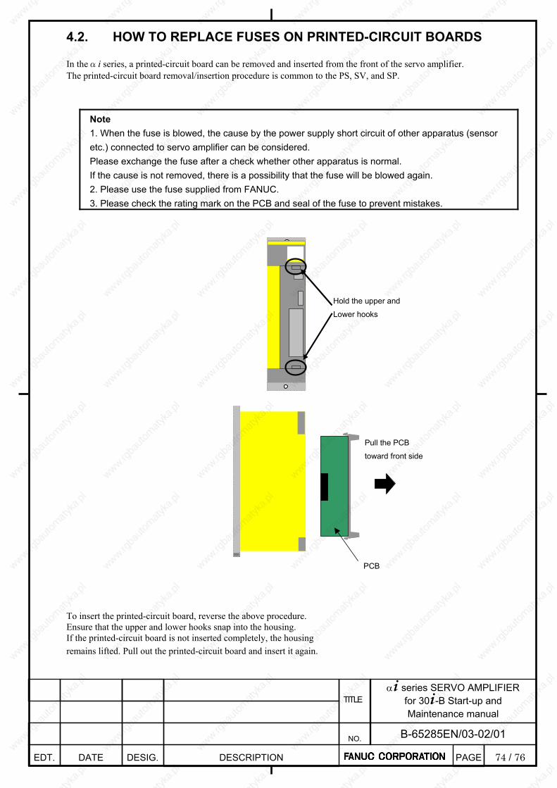
74 / 76
α+ series SERVO AMPLIFIER for 30+-B Start-up and Maintenance manual
EDT. DATE DESIG. DESCRIPTION
B-65285EN/03-02/01 NO.
TITLE
PAGE
4.2. HOW TO REPLACE FUSES ON PRINTED-CIRCUIT BOARDS In theαi series, a printed-circuit board can be removed and inserted from the front of the servo amplifier. The printed-circuit board removal/insertion procedure is common to the PS, SV, and SP.
Note 1. When the fuse is blowed, the cause by the power supply short circuit of other apparatus (sensor etc.) connected to servo amplifier can be considered. Please exchange the fuse after a check whether other apparatus is normal. If the cause is not removed, there is a possibility that the fuse will be blowed again. 2. Please use the fuse supplied from FANUC. 3. Please check the rating mark on the PCB and seal of the fuse to prevent mistakes.
Hold the upper and
Lower hooks
Pull the PCB
toward front side
PCB
To insert the printed-circuit board, reverse the above procedure. Ensure that the upper and lower hooks snap into the housing. If the printed-circuit board is not inserted completely, the housing remains lifted. Pull out the printed-circuit board and insert it again.

75 / 76
α+ series SERVO AMPLIFIER for 30+-B Start-up and Maintenance manual
EDT. DATE DESIG. DESCRIPTION
B-65285EN/03-02/01 NO.
TITLE
PAGE
4.2.1 Power Supply There is one fuse on the printed-circuit board for SP.
Symbol Ordering number Rating FU1 A60L-0001-0290#LM32C 3.2A/48V
Printed circuit board
FU1(3.2A)
(Rating indicated in white)
4.2.2 Servo amplifier There is one fuse on the printed-circuit board for SP.
Symbol Ordering number Rating FU1 A60L-0001-0290#LM32C 3.2A/48V
(1) 60/90mm width servo amplifier
Printed circuit board
FU1(3.2A)
(Rating indicated in white)
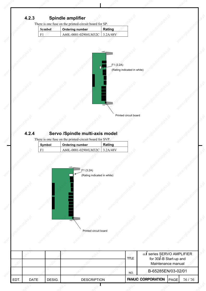
76 / 76
α+ series SERVO AMPLIFIER for 30+-B Start-up and Maintenance manual
EDT. DATE DESIG. DESCRIPTION
B-65285EN/03-02/01 NO.
TITLE
PAGE
4.2.3 Spindle amplifier There is one fuse on the printed-circuit board for SP.
Symbol Ordering number Rating F1 A60L-0001-0290#LM32C 3.2A/48V
Printed circuit board
F1 (3.2A)
(Rating indicated in white)
4.2.4 Servo /Spindle multi-axis model There is one fuse on the printed-circuit board for SVP.
Symbol Ordering number Rating F1 A60L-0001-0290#LM32C 3.2A/48V
Printed circuit board
F1 (3.2A)
(Rating indicated in white)