da-720 series windows software user's manual · • mpeg dtv-dvd audio decoder (mpeg-2, aac)...
TRANSCRIPT

DA-720 Series Windows Software User’s Manual
Edition 2.0, March 2018
www.moxa.com/product
© 2018 Moxa Inc. All rights reserved.

DA-720 Series Windows Software User’s Manual
The software described in this manual is furnished under a license agreement and may be used only in accordance with the terms of that agreement.
Copyright Notice
© 2018 Moxa Inc. All rights reserved.
Trademarks
The MOXA logo is a registered trademark of Moxa Inc. All other trademarks or registered marks in this manual belong to their respective manufacturers.
Disclaimer
Information in this document is subject to change without notice and does not represent a commitment on the part of Moxa.
Moxa provides this document as is, without warranty of any kind, either expressed or implied, including, but not limited to, its particular purpose. Moxa reserves the right to make improvements and/or changes to this manual, or to the products and/or the programs described in this manual, at any time.
Information provided in this manual is intended to be accurate and reliable. However, Moxa assumes no responsibility for its use, or for any infringements on the rights of third parties that may result from its use.
This product might include unintentional technical or typographical errors. Changes are periodically made to the information herein to correct such errors, and these changes are incorporated into new editions of the publication.
Technical Support Contact Information
www.moxa.com/support
Moxa Americas Toll-free: 1-888-669-2872 Tel: +1-714-528-6777 Fax: +1-714-528-6778
Moxa China (Shanghai office) Toll-free: 800-820-5036 Tel: +86-21-5258-9955 Fax: +86-21-5258-5505
Moxa Europe Tel: +49-89-3 70 03 99-0 Fax: +49-89-3 70 03 99-99
Moxa Asia-Pacific Tel: +886-2-8919-1230 Fax: +886-2-8919-1231
Moxa India Tel: +91-80-4172-9088 Fax: +91-80-4132-1045

Table of Contents
1. Introduction ...................................................................................................................................... 1-1 Software Components ......................................................................................................................... 1-2
2. System Initialization ......................................................................................................................... 2-1 Overview ........................................................................................................................................... 2-2
Initializing User Settings .............................................................................................................. 2-2 3. Configuring the Serial Interface ........................................................................................................ 3-1
Overview ........................................................................................................................................... 3-2 Configuring Serial Interface Mode ......................................................................................................... 3-2
4. Enabling Embedded Filters ................................................................................................................ 4-1 Unified Write Filter .............................................................................................................................. 4-2
Overview .................................................................................................................................... 4-2 Configuring File-Based Write Filter ................................................................................................. 4-2
5. Examples........................................................................................................................................... 5-1 Watchdog Function ............................................................................................................................. 5-2
Enabling the Watchdog Function .................................................................................................... 5-2 LED Indicators .................................................................................................................................... 5-3
Displaying and Controlling the LED On/Off Status ............................................................................ 5-3 Serial Interface .................................................................................................................................. 5-4
Displaying and Controlling the UART Mode...................................................................................... 5-4 Relay Output ...................................................................................................................................... 5-6
Displaying the Relay Status and Changing the Status to High or Low ................................................. 5-6 6. System Recovery ............................................................................................................................... 6-1
Recovery Environment ........................................................................................................................ 6-2 Recovery Procedure ............................................................................................................................ 6-2 Saving the System Image to the USB Drive ......................................................................................... 6-10
7. DE-PRP-HSR-EF Expansion Module .................................................................................................... 7-1 Software Installation ........................................................................................................................... 7-2
Installing the DE-PRP-HSR-EF Utility .............................................................................................. 7-2 Checking the PRP/HSR Related Service and Program ....................................................................... 7-5
Configuring the DE-PRP-HSR-EF ........................................................................................................... 7-8 Setting the Operating Mode .......................................................................................................... 7-8 Getting the DE-PRP-HSR-EF Status ................................................................................................ 7-9 Getting the FPGA Version ........................................................................................................... 7-10 Getting the Status of the Supervision Frame ................................................................................. 7-11 Configuring Alert Notifications ..................................................................................................... 7-11
API Reference .................................................................................................................................. 7-15 Overview .................................................................................................................................. 7-15
API Functions ................................................................................................................................... 7-15 Set Operating Mode ................................................................................................................... 7-15 Get RX/TX Counters .................................................................................................................. 7-19

1 1. Introduction
Thank you for buying Moxa’s DA-720 panel computer. This model of the DA-720 comes with the Windows 10 Enterprise LTSB 2016 software platform, which provides a simple and familiar development environment for your various industrial applications needs.
The following topics are covered in this chapter:
Software Components

DA-720 Series UM for Windows Introduction
1-2
Software Components The Windows 10 Enterprise LTSB preinstalled on the DA-720 computer consists of the following:
Windows 10 Enterprise LTSB (by CTOS) Core OS: • 64-bit support • Remote Client • Remote Procedure Call Applications and Services Development: • .Net Framework 4.6 • Remote Desktop Protocol 10 • COM OLE Application Support • COM+ Application Support • MSMQ (message queuing) • Work Folders Client Internet Services: • Internet Explorer 11 • IIS 10 File Systems and Data Storage: • Windows Data Access Components • Windows Backup and Restore Diagnostics: • Common Diagnostic Tools • Problem Reports and Solutions Graphic and Multimedia Tools: • MPEG DTV-DVD Audio Decoder (MPEG-2, AAC) • MPEG Layer-3 Audio Codecs (MP3) • MPEG4 Decoders • Windows Media Video VC-1 (WMV) Codecs • DirectX and Windows Device Experience • Create and play DVDs • Photo Viewer • Remote media streaming • Windows Media Player • Windows Mail • Microsoft Print to PDF • Internet Printing Client • Windows Fax and Scan • XPS Viewer • XPS Services Management: • Group Policy Management • Windows Management Instrument (WMI) • Windows Update

DA-720 Series UM for Windows Introduction
1-3
Networking: • Extensible Authentication Protocol (EAP) • Internet Authentication Service • Telnet Server • Bluetooth • Domain Services • Network Access Protection • Network and Sharing Center • Quality of Service • Remote Access Service (RAS) • Telephony API Client • Windows Firewall • Wireless Networking Security: • Credential Roaming Service • Credentials and Certificate Management • Windows Authorization Manager (AzMan) • Windows Security Center • Active Directory Rights Management • Security Base • Encrypted File System (EFS) • MS Antimalware • Windows Defender Embedded Features: • Unified Write Filter (UWF) • Message Box Default Reply • Registry Filter • The Microsoft Web Services on Devices API (WSDAPI) for .NET Embedded Self-Health Diagnostics: SNMP-based remote scripting layer for monitoring, reporting, and control

2 2. System Initialization
This chapter covers the initial system settings on the DA-720 computer after you boot up the computer for the first time.
The following topics are covered in this chapter:
Overview
Initializing User Settings

DA-720 Series UM for Windows System Initialization
2-2
Overview Like most laptop computers, you must first create a user account and configure the user account settings.
Initializing User Settings 1. When you boot the embedded computer for the first time, you will be asked the following four questions:
(1) What's your home country/region? (2) What's your preferred app language? (3) What keyboard layout would you like to use? (4) What time zone are you in?
Choose your answers and click Next.
2. Click Use Express settings.
3. Provide User name, Password, and Password hint, and click Next to create a user account on the computer.

DA-720 Series UM for Windows System Initialization
2-3
You can start using the DA-720 embedded computer once the user account is created.

3 3. Configuring the Serial Interface
This chapter describes how to configure the serial interface on the DA-720 computer.
The following topics are covered in this chapter:
Overview
Configuring Serial Interface Mode

DA-720 Series UM for Windows Configuring Serial Interface
3-2
Overview The DA-720 supports three serial modes: RS232, RS485-2-wire, and RS422/RS485-4-wire. These modes can be configured either on COM1 or COM2 port.
Configuring Serial Interface Mode To change the serial interface mode settings, do the following:
1. In the Start menu select All apps Moxa mxSetSerialInterface.
2. Select a Port for the serial interface.

DA-720 Series UM for Windows Configuring Serial Interface
3-3
3. Select the specific Mode for the serial interface.
4. Click OK.
4 4. Enabling Embedded Filters
This chapter describes how to operate the embedded features on the DA-720 computer.
The following topics are covered in this chapter:
Unified Write Filter
Overview
Configuring File-Based Write Filter

DA-720 Series UM for Windows Enabling Embedded Filters
4-2
Unified Write Filter
Overview What is UWF?
The Unified Write Filter (UWF) is a feature to protect physical storage media from data writes. UWF intercepts all write attempts to a protected volume and redirects those write attempts to a virtual overlay. This improves the reliability and stability of your device and reduces the wear on write-sensitive media, such as flash memory media like solid-state drives.
About UWF Overlay
UWF intercepts all modifications to any sector on a protected volume. A sector is the smallest unit that can be changed on a storage volume. Any time the file system attempts to modify a protected sector, UWF instead copies the sector from the protected volume to the overlay, and then modifies the overlay instead. If an application attempts to read from that sector, UWF returns the data from the overlay instead, so that the system maintains the appearance of having written to the volume, while the volume remains unchanged.
Source: www.microsoft.com
Configuring File-Based Write Filter
1) Enabling or Disabling the UWF Function
To enable the UWF function, do the following:
1. Select Control Panel in the Windows Start menu.
2. In the left panel, click Programs.

DA-720 Series UM for Windows Enabling Embedded Filters
4-3
3. Click on the Turn Windows features on or off link under Programs and Features, select Unified Write Filter from the list, and click OK.
4. Click Restart now to apply the changes.

DA-720 Series UM for Windows Enabling Embedded Filters
4-4
2) Configuring the UWF Overlay Settings
To configure the UWF overlay settings, do the following:
1. Type cmd in the Windows Start menu field and press Enter to open a terminal.
2. Run the following command to protect the computer volume C:
uwfmgr volume protect C:
3. Run the following command to enable UWF protection:
uwfmgr filter enable

DA-720 Series UM for Windows Enabling Embedded Filters
4-5
4. Run the following command to exclude files in the C:\Program Files folder from UWF protection:
uwfmgr file Add-Exclusion C:\Program Files
5. Exit from the terminal and restart your computer for the changes to take effect.
After restarting your computer, you can check the UWF status by running the uwfmgr get-config command in a terminal.
To test the UWF protection:
1. After you enable UWF protection, create files both in the C:\Program Files and the C:\ folders.
2. Restart the computer.
Only the file that you created in the C:\Program Files should exist. The file that you created in the C:\ folder is erased. To disable the UWF protection, open a terminal and run the uwfmgr filter disable command.

5 5. Examples
This chapter describes how to use the different functions of the DA-720 with examples.
The following topics are covered in this chapter:
Watchdog Function
Enabling the Watchdog Function
LED Indicators
Displaying and Controlling the LED On/Off Status
Serial Interface
Displaying and Controlling the UART Mode
Relay Output
Displaying the Relay Status and Changing the Status to High or Low

DA-720 Series UM for Windows Examples
5-2
Watchdog Function An executable file, watchdog.exe that enables the watchdog function, is provided in the software DVD that ships with the computer.
Enabling the Watchdog Function To enable the watchdog function on your computer using the watchdog.exe file, do the following:
1. Create c:\programs\example folder and copy the following files into the folder:
mxdwg.dll: <Software DVD>\examples\DA720-W10-example\3.lib\mxwdg mxGeneralIo.dll: <Software DVD>\examples\DA720-W10-example\3.lib\MxGeneralIo Watchdog.exe: <Software DVD>\examples\DA720-W10-example\Release\x64\
2. Run Watchdog.exe.
You must press Enter every 10 seconds to prevent the system from restarting.
If you want to stop the watchdog function and exit the program, type q.

DA-720 Series UM for Windows Examples
5-3
LED Indicators An executable file, LED.exe that displays and controls the status of the LEDs, is provided in the software DVD that ships with the computer.
Displaying and Controlling the LED On/Off Status To display the status of the LEDs and to switch the LEDs On or Off, do the following:
1. Copy the following files from the product software DVD:
mxgpio.dll: <Software DVD>\examples\DA720-W10-example\3.lib\mxgpio\x64 mxGeneralIo.dll: <Software DVD>\examples\DA720-W10-example\3.lib\MxGeneralIo LED.exe: <Software DVD>\examples\DA720-W10-example\Release\x64\
2. Run LED.exe.
3. Select 1 to get the value of the current LED.
NOTE The LED port numbers 0 to 5 are used to represent the LEDs 1 to 6 on the computer's front panel.

DA-720 Series UM for Windows Examples
5-4
4. Select 2 to change the status (On, Off) of the current LED.
Serial Interface An executable file, UartMode.exe that displays the status and controls the UART mode of the computer is provided in the software DVD that ships with the computer.
Displaying and Controlling the UART Mode To display the status of the UART interface and to set the UART mode, do the following:
1. Copy the following files from the product software DVD:
mxsp.dll, SysInfo.dll, SysInfo.sys, SysInfoX64.sys: <Software DVD>\examples\DA720-W10-example\3.lib\mxsp\x64 mxGeneralIo.dll: <Software DVD>\examples\DA720-W10-example\3.lib\MxGeneralIo UartMode.exe: <Software DVD>\examples\DA720-W10-example\Release\x64\
2. Run UartMode.exe.

DA-720 Series UM for Windows Examples
5-5
3. Type 2 to set the serial interface and follow the onscreen instructions.
4. Type 1 to display the current serial interface settings.

DA-720 Series UM for Windows Examples
5-6
Relay Output An executable file, Relay.exe that displays the relay status and helps you change its status is provided in the software DVD that ships with the computer.
Displaying the Relay Status and Changing the Status to High
or Low To display the relay status and to set the status to high or low, do the following:
1. Copy the following files from the product software DVD:
mxgpio.dll: <Software DVD>\examples\DA720-W10-example\3.lib\mxgpio\x64 mxGeneralIo.dll: <Software DVD>\examples\DA720-W10-example\3.lib\MxGeneralIo Relay.exe: <Software DVD>\examples\DA720-W10-example\Release\x64\
2. Run Relay.exe.
3. Type 2 to set the serial interface and follow the onscreen instructions.

DA-720 Series UM for Windows Examples
5-7
4. Type 1 to display the current serial interface settings.

6 6. System Recovery
This chapter describes the Windows 10 Enterprise LTSB platform recovery process in the event of system instability.
The following topics are covered in this chapter:
Recovery Environment
Recovery Procedure
Saving the System Image to the USB Drive

DA-720 Series UM for Windows System Recovery
6-2
Recovery Environment The recovery environment consists of the DA-720 panel computer and a bootable USB disk that contains the recovery programs and system image file.
The hardware used includes a PC, a DA-720 computer, and a USB disk with the recovery programs.
NOTE The USB disk should have at least 8 GB of free space.
Recovery Procedure Step 1: Prepare your USB drive 1. Run the tuxboot-windows-23.exe program from the <Software DVD>\recovery folder, select the Pre
Downloaded option, and then click on the … button as shown below:
USB Disk (Recovery data included)
DA-720
USB Ports

DA-720 Series UM for Windows System Recovery
6-3
2. Browse to and select the CloneZilla ISO file from the <Software DVD>\recovery folder.
3. Select the USB Drive type and the Drive, and then click OK to continue.

DA-720 Series UM for Windows System Recovery
6-4
The boot files will be copied to your USB drive.
4. Once the boot files are copied, click Exit to stop the program.
5. Manually copy the os_image directory from the <Software DVD>\recovery folder to the
\home\partimag\ folder on the USB drive.

DA-720 Series UM for Windows System Recovery
6-5
Step 2: Change the BIOS Settings You will need to change the BIOS settings of your computer to enable it to boot from the USB disk.
1. Turn on the computer and press F2 till you hear a beep and the BIOS setup menu is displayed.
2. Select the Boot tab and then select Legacy. Press Enter to continue.
3. Select Boot Type Order.

DA-720 Series UM for Windows System Recovery
6-6
4. Select the USB disk and then press “+” to move it to the first boot device position.
WARNING
An incorrect boot priority will lead to recovery failure.
5. Press F10 and then press Enter to save and exit the BIOS setup.
Step 3: Restore the system from USB drive Connect the USB disk to any of the DA-720’s USB ports and then reboot the computer. The system will boot from the USB disk and the System Save & Restore utility is displayed.
1. In the utility window, select the clonezilla live restore disk option.

DA-720 Series UM for Windows System Recovery
6-7
2. Wait for the USB drive boot process to finish.
3. Enter y to continue the restore process.

DA-720 Series UM for Windows System Recovery
6-8
4. Enter y to confirm again.
5. Wait for the process to finish.

DA-720 Series UM for Windows System Recovery
6-9
6. Select (0) Poweroff to power off the computer.
7. Remove the USB drive after the computer has been powered off.
Step 4: Change the BIOS Settings to Boot from the Original Disk Now you will need to change the boot priority so that the computer can boot from the original disk.
As the system reboots, press F2 to enter the BIOS setup menu.
1. Select Hard Disk Boot Priority and then press + to move to the first boot device position, and then press Enter. Make sure the hard disk has first boot priority.
2. Press F10 and then press Enter to save and exit BIOS settings.

DA-720 Series UM for Windows System Recovery
6-10
Step 5: Reboot the Computer You need to wait about 10 to 15 minutes for the system to restart two times automatically, since the system configuration files will be initiated while booting up for the first time. Do not turn off the computer or shut down the computer while the system is restarting; otherwise, the IIS service will be terminated. When the operating system has successfully launched, you will need to restart your computer so that the new settings can be activated.
Saving the System Image to the USB Drive You may also save the current system image to the USB drive for system recovery in case the system crashes. Before saving the system image to the USB drive, we suggest you remove all files under \home\partimag\ on the USB drive. In addition, change the BIOS settings to make the USB drive the first boot priority.
When the system boots up, do the following:
1. Select clonezilla live save disk.

DA-720 Series UM for Windows System Recovery
6-11
2. Wait for the USB drive boot process to finish.
3. Enter y to continue.

DA-720 Series UM for Windows System Recovery
6-12
4. Wait for the process to finish.
5. Select (0) Poweroff so that the computer will power off when the process is finished.

7 7. DE-PRP-HSR-EF Expansion Module
This chapter describes how to operate the DE-PRP-HSR-EF card on a DA-720 computer, and includes information on configuring the DE-PRP-HSR-EF function using the configuration utility.
The following topics are covered in this chapter:
Software Installation
Installing the DE-PRP-HSR-EF Utility
Checking the PRP/HSR Related Service and Program
Configuring the DE-PRP-HSR-EF
Setting the Operating Mode
Getting the DE-PRP-HSR-EF Status
Getting the FPGA Version
Getting the Status of the Supervision Frame
Configuring Alert Notifications
API Reference
Overview
API Functions
Set Operating Mode
Get RX/TX Counters

DA-720 Series UM for Windows DE-PRP-HSR-EF Expansion Module
7-2
Software Installation
Installing the DE-PRP-HSR-EF Utility 1. Extract the DE-PRP-HSR_V1.0_Utility.zip file and run WinPcap-4-1-3.exe to install the WinPcap setup
package.

DA-720 Series UM for Windows DE-PRP-HSR-EF Expansion Module
7-3
2. Obtain the MxPrpSetup.msi file on the DE-PRP-HSR-EF Software CD/DVD or download the file from Moxa’s support website at http://www.moxa.com/support/download_center.asp. Then, save the file on the DA-720 computer.
3. Double-click on the MxPrpSetup.msi file to start the installation process.
4. Click the Next button on the welcome screen.

DA-720 Series UM for Windows DE-PRP-HSR-EF Expansion Module
7-4
5. Accept the default installation directory or click Browse to select one and Click Next.
6. Click Next to continue.

DA-720 Series UM for Windows DE-PRP-HSR-EF Expansion Module
7-5
7. Click Close to complete the installation. The Moxa PRP Service will be installed on the computer.
Checking the PRP/HSR Related Service and Program 1. In the Windows Programs and Features window, check the software version.

DA-720 Series UM for Windows DE-PRP-HSR-EF Expansion Module
7-6
2. Check if the network adapter is renamed correctly. The network adapter names should have the prefix PRPHSREthernet as shown below:

DA-720 Series UM for Windows DE-PRP-HSR-EF Expansion Module
7-7
3. Check if the network connections are renamed correctly based on the network adapter name.
4. Wait for 1 minute to confirm that the PRP/HSR service is running continuously without stopping.

DA-720 Series UM for Windows DE-PRP-HSR-EF Expansion Module
7-8
5. Check if the PRPSuperVisionFrame.exe is running correctly.
Configuring the DE-PRP-HSR-EF You can use the Moxa PRP Settings utility to set the operating mode on the DE-PRP-HSR-EF.
Setting the Operating Mode 1. Open the Moxa PRP Settings utility from the Start menu.
2. If more than one DE-PRP-HSR-EF is installed on the computer, select the index (1 to 3) of the DE-PRP-HSR-EF that you want to configure from the Module Index drop-down list.
DA-720 Series UM for Windows DE-PRP-HSR-EF Expansion Module
7-9
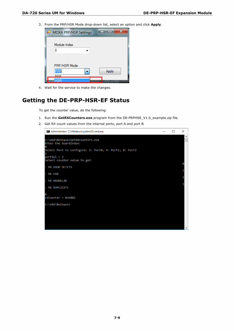
3. From the PRP/HSR Mode drop-down list, select an option and click Apply.
4. Wait for the service to make the changes.
Getting the DE-PRP-HSR-EF Status To get the counter value, do the following:
1. Run the GetRXCounters.exe program from the DE-PRPHSR_V1.0_example.zip file.
2. Get RX count values from the internal ports, port A and port B

DA-720 Series UM for Windows DE-PRP-HSR-EF Expansion Module
7-10
3. Get the TX count value.
Getting the FPGA Version 1. Execute the GetFPGAVersion.exe program
2. Check if the read status and the firmware version are correct.

DA-720 Series UM for Windows DE-PRP-HSR-EF Expansion Module
7-11
Getting the Status of the Supervision Frame Open Wireshark using the hsr_prp_supervision filter and check if the Supervision frame is sent correctly.
Configuring Alert Notifications
Setting Custom Actions
1. Connect the PRP/HSR card with a RedBox.
2. Stop the Moxa PRP/HSR service.
3. Check if the relay output is set to high.

DA-720 Series UM for Windows DE-PRP-HSR-EF Expansion Module
7-12
4. Add the relay output program to AlertNotification.cmd located in the AlertNotification folder.

DA-720 Series UM for Windows DE-PRP-HSR-EF Expansion Module
7-13

DA-720 Series UM for Windows DE-PRP-HSR-EF Expansion Module
7-14
5. Check the current status of the relay using the RelaySample.exe test program.
(The RelaySample.exe program is available in the DA-720-Win10_V1.0_Example.zip under the examples folder)
6. Start the Moxa PRP/HSR service.
7. Disconnect all connections on port A and port B
8. Check if the relay output is set to low

DA-720 Series UM for Windows DE-PRP-HSR-EF Expansion Module
7-15
API Reference
Overview The Moxa PRP/HSR API provides a set of C functions for communicating with hardware devices. The Moxa PRP/HSR API supports the following tasks:
• Setting the operating mode (PRP/HSR).
• Getting RX/TX counters
API Functions
Set Operating Mode
SetPrpMode Set the operating mode to PRP mode.
SetHHsrMode Set the operating mode to HSR mode.
SetPRPMode
int SetPrpMode(UINT8 slaveAddr);
Parameters
slaveAddr : The system management bus (smbus) slave address.
Return Value
Return value(ret) is zero on success, a negative error code on failure.
ret = 0 : Success
ret = -1: Error
Description
The SetPRPMode function is used to set the operating mode to PRP mode.
Example
#include "stdafx.h"
#include <windows.h>
#include "mxprp.h"
bool CheckMxPrpService();
#define LED_INDEX_PRP 0

DA-720 Series UM for Windows DE-PRP-HSR-EF Expansion Module
7-16
/*****************************************************************/
int _tmain(int argc, _TCHAR* argv[])
{
int boardIndex = 0;
int ledIndex = LED_INDEX_PRP;
UINT8 slaveAddr = 0x0;
bool isServiceExist = false;
isServiceExist = CheckMxPrpService();
if(isServiceExist==true)
{
printf("mxPrpService is running, to run this program, please stop the
mxPrpService\n");
printf("Exit the program\n");
return 0;
}
if(argc < 2)
{
/* Get user selection for smbus slave address */
printf("Enter the boardIndex:\n");
scanf("%d", &boardIndex);
}
else
{
boardIndex = _wtol(argv[1]);
}
slaveAddr = SMBUS_SLAVE_ADDRESS
slaveAddr += (UINT8)boardIndex;
/* Set the PRP mode */
SetPrpMode(slaveAddr);
/* Set the link mode */
SetLinkSpeedMode(slaveAddr);
/* Set the module led*/
ConfigureGpioMode(slaveAddr, ledIndex);
SetLedValue(slaveAddr, ledIndex);
return 0;
}
bool CheckMxPrpService()
{
bool isServiceExists = false;
HANDLE hMutex;
hMutex = CreateMutex(
NULL, // default security descriptor
FALSE, // mutex not owned
TEXT("Global\\MxPrpSvcMutex")); // object name
if (hMutex == NULL)

DA-720 Series UM for Windows DE-PRP-HSR-EF Expansion Module
7-17
{
printf("CreateMutex error: %d\n", GetLastError() );
}
else
{
if ( GetLastError() == ERROR_ALREADY_EXISTS )
{
isServiceExists = true;
}
else
{
isServiceExists = false;
/* No service is running, now we can close the mutex and run our program
*/
CloseHandle(hMutex);
}
}
return isServiceExists;
}
SetHSRMode
int SetHsrMode(UINT8 slaveAddr);
Parameters
slaveAddr : The smbus slave address.
Return Value
Return value (ret) is zero on success, a negative error code on failure.
ret = 0 : Success ret = -1: Error
Description
The SetHSRMode function is used to set the operating mode to HSR mode.
Example
#include "stdafx.h"
#include <windows.h>
#include "mxprp.h"
bool CheckMxPrpService();
#define LED_INDEX_HSR 1

DA-720 Series UM for Windows DE-PRP-HSR-EF Expansion Module
7-18
/*****************************************************************/
int _tmain(int argc, _TCHAR* argv[])
{
int boardIndex = 0;
int ledIndex = LED_INDEX_HSR;
UINT8 slaveAddr = 0x0;
bool isServiceExist = false;
isServiceExist = CheckMxPrpService();
if(isServiceExist==true)
{
printf("mxPrpService is running, to run this program, please stop the
mxPrpService\n");
printf("Exit the program\n");
return 0;
}
if(argc < 2)
{
/* Get user selection for smbus slave address */
printf("Enter the boardIndex:\n");
scanf("%d", &boardIndex);
}
else
{
boardIndex = _wtol(argv[1]);
}
slaveAddr = SMBUS_SLAVE_ADDRESS
slaveAddr += (UINT8)boardIndex;
/* Set the HSR mode */
SetHsrMode(slaveAddr);
/* Set the link mode */
SetLinkSpeedMode(slaveAddr);
/* Set the module led*/
ConfigureGpioMode(slaveAddr, ledIndex);
SetLedValue(slaveAddr, ledIndex);
return 0;
}
bool CheckMxPrpService()
{
bool isServiceExists = false;
HANDLE hMutex;
hMutex = CreateMutex(
NULL, // default security descriptor
FALSE, // mutex not owned
TEXT("Global\\MxPrpSvcMutex")); // object name

DA-720 Series UM for Windows DE-PRP-HSR-EF Expansion Module
7-19
if (hMutex == NULL)
{
printf("CreateMutex error: %d\n", GetLastError() );
}
else
{
if ( GetLastError() == ERROR_ALREADY_EXISTS )
{
isServiceExists = true;
}
else
{
isServiceExists = false;
/* No service is running, now we can close the mutex and run our program
*/
CloseHandle(hMutex);
}
}
return isServiceExists;
}
Get RX/TX Counters
GetRxCounter Get the RX counters from hardware device
GetTxCounter Get the TX counters from hardware device
GetRxCounter
int GetRxCounter(UINT8 slaveAddr, UINT8 portSel, unsigned short counterOffset, unsigned short *rxCounter);
Parameters
slaveAddr : The smbus slave address.
portSel: Port select, interlink, port A or port B.
counterOffset: Counter address offset.
rxCounter: The RX counter value.
Return Value
Return value(ret) is zero on success, a negative error code on failure.
ret = 0 : Success
Description
The GetRXCounter function is used to obtain the RX counter of the interlink ports, port A and port B.

DA-720 Series UM for Windows DE-PRP-HSR-EF Expansion Module
7-20
Example
#include "stdafx.h"
#include <windows.h>
#include "mxprp.h"
bool CheckMxPrpService();
unsigned short ReverseBytes(unsigned short value);
unsigned int GetRxGoodOctets(UINT8 slaveAddr, UINT8 portSel);
unsigned int GetRxErrOctets(UINT8 slaveAddr, UINT8 portSel);
unsigned int GetRxWrongLan(UINT8 slaveAddr, UINT8 portSel);
unsigned int GetRxDuplicate(UINT8 slaveAddr, UINT8 portSel);
/*****************************************************************/
int _tmain(int argc, _TCHAR* argv[])
{
UINT8 portSel = 0;
UINT8 funcSel = 0;
unsigned short counterOffset = 0;
unsigned int rxCounter = 0x0;
int boardIndex = 0;
UINT8 slaveAddr = 0x0;
bool isServiceExist = false;
isServiceExist = CheckMxPrpService();
if(isServiceExist==true)
{
printf("mxPrpService is running, to run this program, please stop the
mxPrpService\n");
printf("Exit the program\n");
return 0;
}
/* Get user selection for smbus slave address */
printf("Enter the boardIndex:\n");
scanf("%d", &boardIndex);
slaveAddr = SMBUS_SLAVE_ADDRESS;
slaveAddr += boardIndex;
/* Configure Counter Control bit to 1 to update the values in counter registers
*/
printf("Select Port to configure: 2: Port0, 4: Port1, 8: Port2\n");
scanf("%d", &portSel);
printf("portSel = %d\n", portSel);
/* Get the counter value */
printf("Select counter value to get:\n \
0: RX GOOD OCTETS\n \
1: RX ERR\n \
2: RX WRONGLAN\n \
3: RX DUPLICATE\n \
\n");
scanf("%d", &funcSel);
DA-720 Series UM for Windows DE-PRP-HSR-EF Expansion Module
7-21
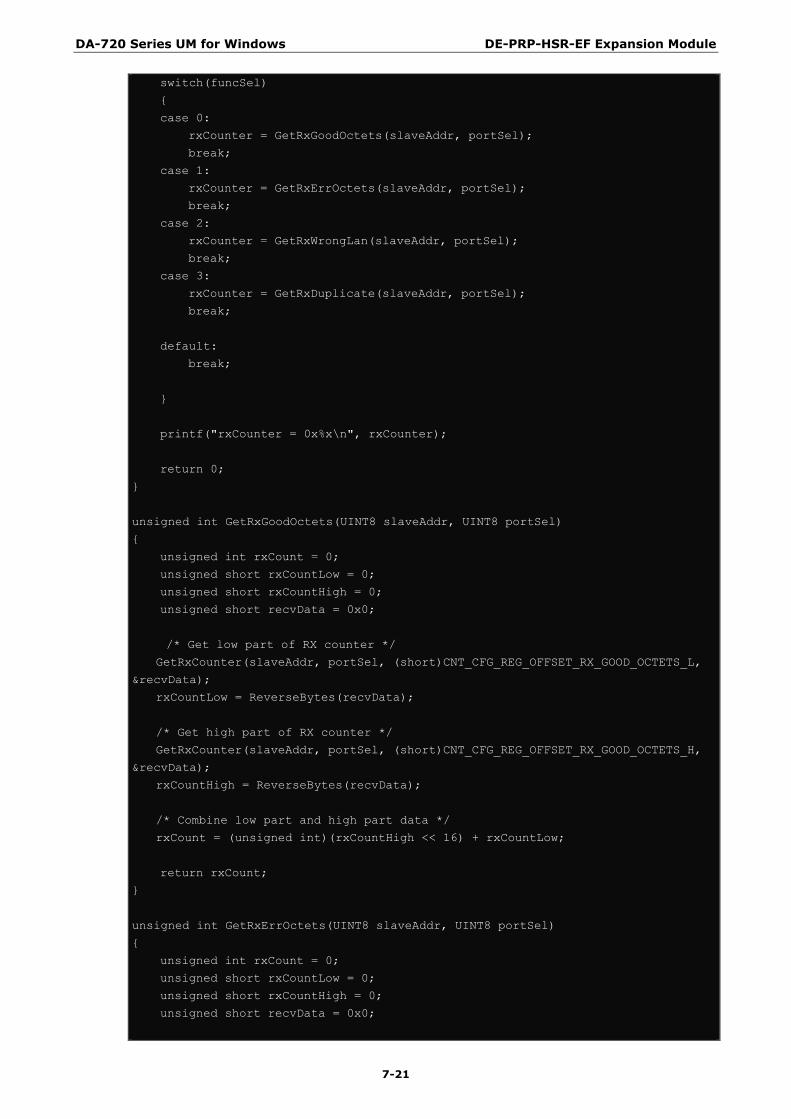
switch(funcSel)
{
case 0:
rxCounter = GetRxGoodOctets(slaveAddr, portSel);
break;
case 1:
rxCounter = GetRxErrOctets(slaveAddr, portSel);
break;
case 2:
rxCounter = GetRxWrongLan(slaveAddr, portSel);
break;
case 3:
rxCounter = GetRxDuplicate(slaveAddr, portSel);
break;
default:
break;
}
printf("rxCounter = 0x%x\n", rxCounter);
return 0;
}
unsigned int GetRxGoodOctets(UINT8 slaveAddr, UINT8 portSel)
{
unsigned int rxCount = 0;
unsigned short rxCountLow = 0;
unsigned short rxCountHigh = 0;
unsigned short recvData = 0x0;
/* Get low part of RX counter */
GetRxCounter(slaveAddr, portSel, (short)CNT_CFG_REG_OFFSET_RX_GOOD_OCTETS_L,
&recvData);
rxCountLow = ReverseBytes(recvData);
/* Get high part of RX counter */
GetRxCounter(slaveAddr, portSel, (short)CNT_CFG_REG_OFFSET_RX_GOOD_OCTETS_H,
&recvData);
rxCountHigh = ReverseBytes(recvData);
/* Combine low part and high part data */
rxCount = (unsigned int)(rxCountHigh << 16) + rxCountLow;
return rxCount;
}
unsigned int GetRxErrOctets(UINT8 slaveAddr, UINT8 portSel)
{
unsigned int rxCount = 0;
unsigned short rxCountLow = 0;
unsigned short rxCountHigh = 0;
unsigned short recvData = 0x0;

DA-720 Series UM for Windows DE-PRP-HSR-EF Expansion Module
7-22
/* Get low part of RX counter */
GetRxCounter(slaveAddr, portSel, (short)CNT_CFG_REG_OFFSET_RX_ERR_L,
&recvData);
rxCountLow = ReverseBytes(recvData);
/* Get high part of RX counter */
GetRxCounter(slaveAddr, portSel, (short)CNT_CFG_REG_OFFSET_RX_ERR_H,
&recvData);
rxCountHigh = ReverseBytes(recvData);
/* Combine low part and high part data */
rxCount = (unsigned int)(rxCountHigh << 16) + rxCountLow;
return rxCount;
}
unsigned int GetRxWrongLan(UINT8 slaveAddr, UINT8 portSel)
{
unsigned int rxCount = 0;
unsigned short rxCountLow = 0;
unsigned short rxCountHigh = 0;
unsigned short recvData = 0x0;
/* Get low part of RX counter */
GetRxCounter(slaveAddr, portSel, (short)CNT_CFG_REG_OFFSET_RX_WRONGLAN_L,
&recvData);
rxCountLow = ReverseBytes(recvData);
/* Get high part of RX counter */
GetRxCounter(slaveAddr, portSel, (short)CNT_CFG_REG_OFFSET_RX_WRONGLAN_H,
&recvData);
rxCountHigh = ReverseBytes(recvData);
/* Combine low part and high part data */
rxCount = (unsigned int)(rxCountHigh << 16) + rxCountLow;
return rxCount;
}
unsigned int GetRxDuplicate(UINT8 slaveAddr, UINT8 portSel)
{
unsigned int rxCount = 0;
unsigned short rxCountLow = 0;
unsigned short rxCountHigh = 0;
unsigned short recvData = 0x0;
/* Get low part of RX counter */
GetRxCounter(slaveAddr, portSel, (short)CNT_CFG_REG_OFFSET_RX_DUPLICATE_L,
&recvData);
rxCountLow = ReverseBytes(recvData);
/* Get high part of RX counter */
GetRxCounter(slaveAddr, portSel, (short)CNT_CFG_REG_OFFSET_RX_DUPLICATE_H,
&recvData);
rxCountHigh = ReverseBytes(recvData);

DA-720 Series UM for Windows DE-PRP-HSR-EF Expansion Module
7-23
/* Combine low part and high part data */
rxCount = (unsigned int)(rxCountHigh << 16) + rxCountLow;
return rxCount;
}
unsigned short ReverseBytes(unsigned short value)
{
return (unsigned short)((value & 0xFFU) << 8 | (value & 0xFF00U) >> 8);
}
bool CheckMxPrpService()
{
bool isServiceExists = false;
HANDLE hMutex;
hMutex = CreateMutex(
NULL, // default security descriptor
FALSE, // mutex not owned
TEXT("Global\\MxPrpSvcMutex")); // object name
if (hMutex == NULL)
{
printf("CreateMutex error: %d\n", GetLastError() );
}
else
{
if ( GetLastError() == ERROR_ALREADY_EXISTS )
{
isServiceExists = true;
}
else
{
isServiceExists = false;
/* No service is running, now we can close the mutex and run our program
*/
CloseHandle(hMutex);
}
}
return isServiceExists;
}

DA-720 Series UM for Windows DE-PRP-HSR-EF Expansion Module
7-24
GetTxCounter
int GetTxCounter(UINT8 slaveAddr, UINT8 portSel, unsigned short counterOffset, unsigned short *rxCounter);
Parameters
slaveAddr : The smbus slave address.
portSel: Port select, interlink, port A or port B.
counterOffset: Counter address offset.
rxCounter: The RX counter value.
Return Value
Return value(ret) is zero on success, a negative error code on failure.
ret = 0 : Success
Description
The GetTXCounter function is used to obtain the TX counter of the interlink port, port A and port B.
Example
Example#include "stdafx.h" #include <windows.h>
#include "mxprp.h"
bool CheckMxPrpService();
unsigned short ReverseBytes(unsigned short value);
unsigned int GetTxOctets(UINT8 slaveAddr, UINT8 portSel);
/*****************************************************************/
int _tmain(int argc, _TCHAR* argv[])
{
UINT8 portSel = 0;
UINT8 funcSel = 0;
unsigned short counterOffset = 0;
unsigned int txCount;
int boardIndex = 0;
UINT8 slaveAddr = 0x0;
bool isServiceExist = false;
isServiceExist = CheckMxPrpService();
if(isServiceExist==true)
{
printf("mxPrpService is running, to run this program, please stop the
mxPrpService\n");
printf("Exit the program\n");
return 0;
}

DA-720 Series UM for Windows DE-PRP-HSR-EF Expansion Module
7-25
/* Get user selection for smbus slave address */
printf("Enter the boardIndex:\n");
scanf("%d", &boardIndex);
slaveAddr = SMBUS_SLAVE_ADDRESS;
slaveAddr += boardIndex;
/* Configure Counter Control bit to 1 to update the values in counter registers
*/
printf("Select Port to configure: 2: Port0, 4: Port1, 8: Port2");
scanf("%d", &portSel);
/* Get TX count */
txCount =GetTxOctets(slaveAddr, portSel);
printf("txCount = %d\n", txCount);
return 0;
}
unsigned int GetTxOctets(UINT8 slaveAddr, UINT8 portSel)
{
unsigned int txCount = 0;
unsigned short txCountLow = 0;
unsigned short txCountHigh = 0;
unsigned short recvData = 0x0;
/* Get low part of TX counter */
GetTxCounter(slaveAddr, portSel, (short)CNT_CFG_REG_OFFSET_TX_OCTETS_L,
&recvData);
txCountLow = ReverseBytes(recvData);
/* Get high part of TX counter */
GetTxCounter(slaveAddr, portSel, (short)CNT_CFG_REG_OFFSET_TX_OCTETS_H,
&recvData);
txCountHigh = ReverseBytes(recvData);
/* Combine low part and high part data */
txCount = (unsigned int)(txCountHigh << 16) + txCountLow;
return txCount;
}
unsigned short ReverseBytes(unsigned short value)
{
return (unsigned short)((value & 0xFFU) << 8 | (value & 0xFF00U) >> 8);
}
bool CheckMxPrpService()
{
bool isServiceExists = false;
HANDLE hMutex;
hMutex = CreateMutex(
NULL, // default security descriptor
FALSE, // mutex not owned
TEXT("Global\\MxPrpSvcMutex")); // object name
DA-720 Series UM for Windows DE-PRP-HSR-EF Expansion Module
7-26
if (hMutex == NULL)
{
printf("CreateMutex error: %d\n", GetLastError() );
}
else
{
if ( GetLastError() == ERROR_ALREADY_EXISTS )
{
isServiceExists = true;
}
else
{
isServiceExists = false;
/* No service is running, now we can close the mutex and run our program
*/
CloseHandle(hMutex);
}
}
return isServiceExists;
}