d6.4 - phase 1 test site platforms and deployment report · phase 1 test site platforms and...
TRANSCRIPT

This project has received funding from the European Union’s Horizon 2020 research and innovation
programme under grant agreement No 731155.
D6.4 - Phase 1 Test Site Platforms and Deployment Report
Deliverable ID D6.4
Deliverable Title Phase 1 Test Site Platforms and Deployment Report
Work Package WP6 – Integration, Test Sites and Evaluation
Dissemination Level PUBLIC
Version 1.0
Date 2018-01-15
Status Final
Lead Editor EDYNA/ALPERIA/ASM
Main Contributors ISMB, UPB (Marta STURZEANU, Mihaela ALBU, Mihai
SANDULEAC), ENIIG, FIT
Published by the Storage4Grid Consortium

LCE-01-2016 - Next generation innovative technologies enabling smart grids, storage and energy system
integration with increasing share of renewables: distribution network
Deliverable nr.
Deliverable Title
Version
D6.4
Phase 1 Test site platforms and deployments report
1.0 – 15/01/2018
Page 2 of 23
Document History
Version Date Author(s) Description
0.1 2017-07-05 EDYNA TOC
0.1 2017-09-11 EDYNA First draft
0.2 2017-09-25 UPB Description of phase 1 test site
Test site components and pictures
Testing plans
Next steps towards phase 2
0.3 2017-09-28 EDYNA Contribution of Edyna/Alperia/ASM to phase 1 test sites in
Bolzano
0.4 2017-11-27 Eniig Contribution of Eniig to phase 1 test sites in Fur
0.5 2017-12-05 EDYNA Updating of descriptions and photos
0.6 2017-12-07 Eniig, UPB Final contributions to Eniig Test site + First review of UPB
0.7 2017-12-15 Alperia Editing by Alperia
0.8 2017-12-17 ISMB, Alperia Introduction by ISMB, minor changes by Alperia
1.0 2018-01-15 Alperia Finalization of the document
Internal Review History
Review Date Reviewer Summary of Comments
2017-12-07 UPB (Marta Sturzeanu) Minor comments
2017-12-18 Eniig (Gitte Wad Thybo) Approved
2017-12-19 UPB (Mihaela Albu) Minor edits - Approved

LCE-01-2016 - Next generation innovative technologies enabling smart grids, storage and energy system
integration with increasing share of renewables: distribution network
Deliverable nr.
Deliverable Title
Version
D6.4
Phase 1 Test site platforms and deployments report
1.0 – 15/01/2018
Page 3 of 23
Table of Contents
Document History ...................................................................................................................................................................................... 2
Internal Review History ............................................................................................................................................................................ 2
Table of Contents ....................................................................................................................................................................................... 3
1 Introduction ........................................................................................................................................................................................ 4
1.1 Scope .......................................................................................................................................................................................... 4
1.2 Related documents........................................................................................................................................................................ 4
2 Test site Bolzano: Cooperative EV charging .......................................................................................................................... 6
2.1 Description of Phase 1 test site ........................................................................................................................................ 6
2.2 Problems faced and lessons learnt ............................................................................................................................... 12
2.3 Testing plans .......................................................................................................................................................................... 12
2.4 Next steps towards Phase 2 ............................................................................................................................................. 12
3 Test site Fur: Storage coordination ......................................................................................................................................... 13
3.1 Description of Phase 1 test site ...................................................................................................................................... 13
3.2 Problems faced and lessons learnt ............................................................................................................................... 13
3.3 Testing plans .......................................................................................................................................................................... 14
3.4 Next steps towards Phase 2 ............................................................................................................................................. 14
4 Test site UPB: Cooperative Storage System Scenario ...................................................................................................... 15
4.1 Description of Phase 1 test site ...................................................................................................................................... 15
4.2 Problems faced and lessons learnt ............................................................................................................................... 20
4.3 Testing plans .......................................................................................................................................................................... 21
4.4 Next steps towards Phase 2 ............................................................................................................................................. 21
Acronyms ..................................................................................................................................................................................................... 22
List of figures .............................................................................................................................................................................................. 23

LCE-01-2016 - Next generation innovative technologies enabling smart grids, storage and energy system
integration with increasing share of renewables: distribution network
Deliverable nr.
Deliverable Title
Version
D6.4
Phase 1 Test site platforms and deployments report
1.0 – 15/01/2018
Page 4 of 23
1 Introduction
The initialization of hardware/software components defined in D6.1 “Phase 1 Test Site Plans” is being stacked
up and further summarized in this document. This deliverable reports the process/issues/solutions for
deployment of equipment and measurement devices installed in three major test sites. It also relates the way
the study case players such as private houses, academic library and public school (perspective) integrate into
the Storage4Grid intelligence framework.
The main contribution is gathered from the three physical sites, providing the essential information about
their subject matters including present photovoltaics, storages and converters as well as the entire process of
installation and settling down the facing issues for the first phase:
Bolzano test site: EDYNA, prepared two sites; in both residential and commercial case the presence
of Electric Vehicle (EV) is highlighted;
o Residential case, a house owned by a private customer with Storage, Photovoltaic (PV)
installation and electrical vehicle (EV)
o Commercial (public), a parking lot for EVs owned by EDYNA itself with several EV chargers
Fur test site: ENIIG prepared a residential test site, which was installed in the former project
GreenCom; this test site is equipped with PV-system and local storage; ;
o Residential case, a single private house in Fur is the subject for the first phase of
development
Bucharest test site: a hybrid home energy with an internal DC bus empowered residential feeder is
the characteristic feature by UPB;
o The tests are being developed at laboratory level
1.1 Scope
The present deliverable publishes the first and highly important challenges and solutions regarding the Test
Sites Deployment and Execution brought in the T6.4 of Storage4Grid Grant Agreement. Deployment,
preparation and implementation of test sites through taking theoretical platform to the reality of physical
systems.
As one of the results generated by work in WP6 “Integration, Test Sites and Evaluation”, in this first phase of
deployment in the field, the components defined in WP1 and WP2 are shaped and adapted to the situation
in the field.
EDYNA supervised and performed all preparation activities in Bolzano test sites, ENIIG did that for the Fur
test site and UPB has overseen monitoring the correctness and continuous operation and execution of test
sites during the period of this phase.
For each test site, a description about the components to be deployed is followed by a set of lessons learnt
during the deployment. To overcome the issues, a clear solution is given in order to fulfill the gap among the
reality and -laboratory. In practical, how to perform the testing is defined in an easy, realistic, stable way.
1.2 Related documents
ID Title Reference Version Date
D2.1 Phase 1 Test Sites Plan [S4G-D2.1] 1.01 2017-08-16
D3.1 Initial S4G Components, Intefaces and Architecture
Specification [S4G-D3.1] 1.0 2017-09-15
D4.1 Initial User-side ESS control system [S4G-D4.1] 1.0 2017-08-30
D4.8 Initial USM Extensions for Storage Systems [S4G-D4.8] 1.0 2017-08-31
D5.3 Initial DSF Connectors for external systems and [S4G-D5.3] 1.0 2017-09-04

LCE-01-2016 - Next generation innovative technologies enabling smart grids, storage and energy system
integration with increasing share of renewables: distribution network
Deliverable nr.
Deliverable Title
Version
D6.4
Phase 1 Test site platforms and deployments report
1.0 – 15/01/2018
Page 5 of 23
services
D6.1 Initial Storage Scenarios and Use Cases [S4G-D6.1] 1.1 2017-06-08

LCE-01-2016 - Next generation innovative technologies enabling smart grids, storage and energy system
integration with increasing share of renewables: distribution network
Deliverable nr.
Deliverable Title
Version
D6.4
Phase 1 Test site platforms and deployments report
1.0 – 15/01/2018
Page 6 of 23
2 Test site Bolzano: Cooperative EV charging
This test site features two scenarios: a residential case and a commercial case.
2.1 Description of Phase 1 test site
2.1.1 Residential Case
The Test Site is executed in a private house close to Bolzano. The house has already a PV plant on the roof
with the following technical features:
Rated (maximal) power: 9,6 kWp;
Average year production: approximately 11 MWh.
The PV structure in the residential case can be found in Figure 1.
Figure 1: Test site for the residential case (Bolzano test site)
The wiring diagram of the original PV plant is depicted in Figure 2.

LCE-01-2016 - Next generation innovative technologies enabling smart grids, storage and energy system
integration with increasing share of renewables: distribution network
Deliverable nr.
Deliverable Title
Version
D6.4
Phase 1 Test site platforms and deployments report
1.0 – 15/01/2018
Page 7 of 23
Figure 2: Wiring diagram of the PV roof plant (Bolzano test site)
The owner of the house has got an EV with the following technical features:
Citroen C-ZERO (02/2013);
Li Ion Battery – capacity 14,5 kWh;
Charger 15 A, 230 V;
Yearly EV use: approximately 10.000 km/year;
Range: 80/90 km (winter); 130/140 km (summer).
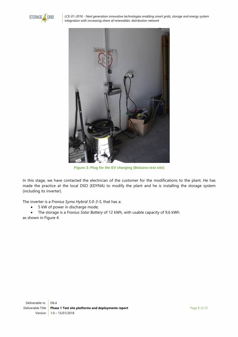
The EV is normally loaded at the electrical system of the house through a single-phase plug (in the house
garage) as shown in Figure 3.
LCE-01-2016 - Next generation innovative technologies enabling smart grids, storage and energy system
integration with increasing share of renewables: distribution network
Deliverable nr.
Deliverable Title
Version
D6.4
Phase 1 Test site platforms and deployments report
1.0 – 15/01/2018
Page 8 of 23
Figure 3: Plug for the EV charging (Bolzano test site)
In this stage, we have contacted the electrician of the customer for the modifications to the plant. He has
made the practice at the local DSO (EDYNA) to modify the plant and he is installing the storage system
(including its inverter).
The inverter is a Fronius Symo Hybrid 5.0-3-S, that has a:
5 kW of power in discharge mode;
The storage is a Fronius Solar Battery of 12 kWh, with usable capacity of 9,6 kWh
as shown in Figure 4.

LCE-01-2016 - Next generation innovative technologies enabling smart grids, storage and energy system
integration with increasing share of renewables: distribution network
Deliverable nr.
Deliverable Title
Version
D6.4
Phase 1 Test site platforms and deployments report
1.0 – 15/01/2018
Page 9 of 23
Figure 4: Inverter Fronius Symo Hybrid (Bolzano test site)
The electrician has completed the plant with a charging station of ASM, a Wall Box single phase 7.4 kW (see
Figure 5), and the first L&G smart meter. In the coming months 3 more L&G meters will be installed. The total
4 L&G meters will be installed in parallel with the 3 existing Edyna meters M1 (interconnection point), M2 (PV
plant), M3 (storage) and at the charging station (no preferential load). See Figure 6.
Figure 5: The new charging station

LCE-01-2016 - Next generation innovative technologies enabling smart grids, storage and energy system
integration with increasing share of renewables: distribution network
Deliverable nr.
Deliverable Title
Version
D6.4
Phase 1 Test site platforms and deployments report
1.0 – 15/01/2018
Page 10 of 23
Figure 6: Wiring diagram with Edyna meters (Bolzano test site)
For the communication of the meters, ALPERIA is going to install a dedicated internet connection, separate
from that of the owner of the house.
2.1.2 Commercial case
We are developing the commercial case in the garage of the South-Tyrol DSO EDYNA. Actually, EDYNA has a
fleet of 11 electric vehicles: 10 VW eUP and 1 Nissan van. Each of these has its own place in the garage with a
charging station. EDYNA is going to increase its electric auto park in the next years.
On the roof of the EDYNA building are installed 2 PV plants: one of 50 kW (peak power) and the other 99 kW
(peak power). The PV plants belong to Alperia Green Power, a subsidiary company of Alperia. The energy
produced by these plants goes directly into the distribution grid, and can therefore not be directly used to
recharge the fleet of BEV. Nevertheless, within the project Edyna will install 2/3 more USM in order to
measure the energy produced by the PV plants and simulate the case of the direct use of this energy.
A storage unit will be installed during phase 2 to optimize the energy supply to charging stations.
Main activities related to the installations during Phase 1 are:
1) Connection to the DSO grid with DSO Meter, as for usual grid connections.
This implies connection request for a new connection with 90 kW (for comprising other charging
stations, which is not included in the project) to the DSO, cable laying works and meter mounting
from DSO side. Without regulare grid connection with DSO meter we cannot start the service of
charging stations for Edyna e-cars.
2) Installation of cables, switchboxes and protections post meter (it’s a private electric installation after
DSO point of delivery).
This is done by an authorized electrician, who will emit Conformity Declaration. Following the new
IEC 61851-1:2017 norm, all the AC plugs have to be equipped with RCD type protection.

LCE-01-2016 - Next generation innovative technologies enabling smart grids, storage and energy system
integration with increasing share of renewables: distribution network
Deliverable nr.
Deliverable Title
Version
D6.4
Phase 1 Test site platforms and deployments report
1.0 – 15/01/2018
Page 11 of 23
3) Installation of Charging Stations.
Charging Stations of type Wall Box single phase 7.4 kW (3 pieces) and Wall Box Triphase 22 kW (2
pieces) are wall mounted. In the site, there are other 6 charging stations, so called dummies, out of
the range of the S4G project.
PHASE WEEK 1 WEEK 2 WEEK 3 WEEK 4 WEEK 5
Request of DSO
connection
DSO offer and
conditions
Installation circuitry
post meter
Installation of
charging stations
4) Installation of the storage: we will evaluate the power and the capacity of the storage on the basis of
the measures of the charging station
5) In this site, we will install 10 L&G smart meter: 5 for the 5 smart charging stations, 1 for all others
dummy charging station, 1 in interconnection point, 1 for the storage, 2 for the 2 PV plants on the
roof.
6) Predisposition of the internet connection in Edyna garage, to have the real time communication with
the smart meters installed.
Figure 7: Edyna garage, the test site with the charging stations installed

LCE-01-2016 - Next generation innovative technologies enabling smart grids, storage and energy system
integration with increasing share of renewables: distribution network
Deliverable nr.
Deliverable Title
Version
D6.4
Phase 1 Test site platforms and deployments report
1.0 – 15/01/2018
Page 12 of 23
2.2 Problems faced and lessons learnt
Problems in the smart meter supply: the Landys and Gyr meter, proposed by the University Politehnica of
Bucharest, because they already tested it with their software, is not easy to purchase in Italy. The other meter,
ISKRA, that is already available in EDYNA, does not communicate with the SMX software already developed
by the UPB partner. In EDYNA we use this meter ISKRA with the official software, and we have no problem;
however the SMX connectivity which is essential for the S4G project (as support for the Intelligent agents)
has to be ensured.
We have met a few problems with the electrician, who did not immediately understand what he should do.
So it was necessary to have more meetings with him.
It is difficult to understand the competence borders of each subject (DSO, Service Provider, Final Customer)
in order to correctly state the position and ownership of the elements (meter, storage system, charging
station and PV plant).
2.3 Testing plans
Use of electric cars, average trips, average kWh consumed, peak consumes, possibility to detect standby of
cars at charging stations, possibility of start/stop remotely operated.
Optimization of the storage to save energy supply from DSO grid. Optimization of the charge cycle for the e-
car to save energy supply from DSO grid.
Tests are finalized to establish if storage has been dimensioned properly, by means of analyzing usual
behavior of e-cars, in order to shave peaks.
2.4 Next steps towards Phase 2
We are going to complete the 2 test sites, residential and commercial, and to start the test.

LCE-01-2016 - Next generation innovative technologies enabling smart grids, storage and energy system
integration with increasing share of renewables: distribution network
Deliverable nr.
Deliverable Title
Version
D6.4
Phase 1 Test site platforms and deployments report
1.0 – 15/01/2018
Page 13 of 23
3 Test site Fur: Storage coordination
This test site features a residential test site, which in phase 1 includes one private house. When the hardware
and software are seen stabile (phase 2), more private houses will be included in this residential test site.
Phase 2 test site also contains a grid side battery at a school and test of the Energy Router (ER) at Eniig
premises in Skive.
3.1 Description of Phase 1 test site
The test site consists of a residential house, which has already been equipped with PV plants with Fronius
Hybrid inverter and Fronius battery energy storage system.
The system was originally equipped with a normal PV inverter but this was replaced with a Fronius hybrid
inverter and battery energy storage in august 2015.
The system has the following specifications:
PV: 16 modules of 195 Wp each, resulting in a total of 3,12 kWp – yearly production approx. 2,950
kWh
Fronius Symo Hybrid 5.0-3-S
Fronius Solar Battery 4.5 with usable energy capacity of 3.6 kWh
Fronius Smart Meter
Additionally to the existing installation, the USM is installed at the Point of Common Coupling (PCC).
The USM consist of a Landis+Gyr E550 smart meter that has been installed in parallel to the already existing
smart meter for billing and the Fronius Smart meter and the SMX. See Figure 8 for details.
The L+G meter has been installed to give accurate measurements of P, Q and I for both upstream and
downstream directions.
The SMX has been installed to pass information for the L+G meter to project database so the Fronius system
can be controlled according to the use cases.
The SMX was connected to the wireless network of the customers’ existing Wi-Fi router.
Figure 8: PV modules; Electrical switchboard with Fronius Smart Meter, Fronius inverter, Fronius battery (Test site Fur)
3.2 Problems faced and lessons learnt
Problems in the smart meter supplies: the Landis + Gyr, recommended by the UPB partner, because has been
already tested with the SMX connectivity, is not easy to purchase in Denmark. This is partly because the
meter E550 ZMG does not include a year counter. This means that it can’t be used for billing purposes in the
event of a failure in the meter and this is not allowed in Denmark.

LCE-01-2016 - Next generation innovative technologies enabling smart grids, storage and energy system
integration with increasing share of renewables: distribution network
Deliverable nr.
Deliverable Title
Version
D6.4
Phase 1 Test site platforms and deployments report
1.0 – 15/01/2018
Page 14 of 23
The problem may also be partly because we only need a small amount of meters and meter producers often
do not want to use a lot of time dealing with only a few number of meters.
However, we did get a quote for meters from the Danish Landis+ Gyr office, but could not order anything
because we were missing the correct ASN code, so that the meter could be configured correctly.
As UPB could not provide us with this, we tried asking Landis + Gyr for a ASN sheet so we could choose from
this. Landis & Gyr was not helpful in getting this.
We have also in coorporation with Partner Lithium Balance investigated using an alternative meter namely
Landis + Gyr E650, which is allowed in Denmark. But as UPB has not used this before, we had to investigate
further to be sure this can be used.
Because of the problems with sourcing a useable meter, UPB was kind to lend us a meter that could be used
for test phase 1.
Regarding the physical installation of the Landis + Gyr meter there was a small issue regarding available wall
space at the installation site. The PV inverter had to be moved a little to have enough wall space for the
meter installation. Fortunately, all cables to the inverter was long enough for the moving, so this was a small
issue at this site, but could potentially be a problem in other sites.
Also, we have concerns regarding the installation of the cable connection between the SMX and the Smart
Meter. The Smart Meter has a modular connector which gives access to the meters by using the RS232
interface. The SMX has a USB connector. To connect these, UPB send us the following:
1. Cable with USB connector in both ends
2. Ethernet cable with modular connector in one end and a RS232 female connector soldered to the
other end. Also the Modular connector was not crimped properly.
3. A RS232 to USB adapter (the most convenient solution)
This setup is not suited for installations at test sites in private homes, as it’s delicate and could break. Instead,
we would recommend using a modular connector to USB adapter in the future and then use a prefabricated
Ethernet path cable in the correct length.
There were also some lessons learnt from setting up the SMX and the connection to this. As the SMX had
already been used at UPB site, this was preconfigured, so this was not a big issue. However, when not having
worked with Raspberry Pie before, there was some learnings in getting used to the command prompt and
the commands in this. Also the guides and wikis seem to have been writing to people that are used to
programming.
Regarding the OpenVPN access to the PC, we had some problems as we have not used it before and did not
know the architecture of it. But when we got the right client files for the PC and understood the architecture
of all PC’s and SMX’s being clients everything worked fine.
The actual installation at the customer was relatively easy and only with minor problems.
3.3 Testing plans
In this stage of the test site we will collect active power (P), voltage (U) and currents (I) from the main USM
meter, but also will simulate acquisition of State of Charge (SoC) from the batteries and power (P) from the
PV-system. The sampling time is in the order of seconds.
This data will be used for local functionalities tested by LESSAg in the system, (GESSCON and any other
external component are simulated, until they will be available to communicate directly with them).
3.4 Next steps towards Phase 2
In the phase 2 in FUR test site the focus will be on the complete integration of the components and a stable
and reliable communication before installing more USM’s in the next test houses. In phase 2 we will also
prepare the grid side storage (to be place nearby a school) and test of the Energy Router at Eniig premises in
Skive.

LCE-01-2016 - Next generation innovative technologies enabling smart grids, storage and energy system
integration with increasing share of renewables: distribution network
Deliverable nr.
Deliverable Title
Version
D6.4
Phase 1 Test site platforms and deployments report
1.0 – 15/01/2018
Page 15 of 23
4 Test site UPB: Cooperative Storage System Scenario
The “Advanced Cooperative Storage Systems” scenario will be addressed in conjunction with the deployment
in the Bucharest test site and be led by partner UPB. A detailed description can be found in D2.1 Initial
Storage Scenarios and Use cases Description of Phase 1 test site.
4.1 Description of Phase 1 test site
This test site is executed in a laboratory setting and features a home hybrid energy system with DC bus,
which will support prosumer functionality, including resilience and service the DSO operation. The energy
exchange in point of common coupling (PCC) is monitored 24/7. The equipment to be deployed are USM
(SMX + meter), energy router, and telecommunication equipment which may allow also different
services to support the grids. To ensure that the local DC grid will be able to supply its critical (local) loads
also during small AC voltage interruptions or during black-outs (the inverter connection to the grid will be
kept un-operational during this period), it is needed to be implemented a local agent which can control the
local resources, including the storage.
In the phase 1 test site only a part of the entire components was installed or adapted for the use-cases of the
project, as following:
2 SMX which communicates in the both downstream and upstream directions, as follows:
Downstream to the Energy Router (ER), the SMX has the role of emulating communication of
set points to ER, allowing in this way to send and read information.
Downstream to a single phase meter - Landis+Gyr with the scope of acquiring the
measurement values (voltage - U, power – P, etc.) every 10 seconds from the system.
Upstream, a simulation of Message Queuing Telemetry Transport (MQTT) messages towards
cloud applications, e.g. GessCon.
Figure 9: SMX box and details of SMX (Test site UPB)

LCE-01-2016 - Next generation innovative technologies enabling smart grids, storage and energy system
integration with increasing share of renewables: distribution network
Deliverable nr.
Deliverable Title
Version
D6.4
Phase 1 Test site platforms and deployments report
1.0 – 15/01/2018
Page 16 of 23
Landis+Gyr ZMG310 meter installed, to measure parameters of the energy flow in the point of
common coupling (PCC). Additional meter and SMX is available in the laboratory to test the meter to
sub-meter communication (main USM to another USM).
a)
b)
Figure 10: Landys+Gyr meter (a) uninstalled and (b) installed and connected to a Raspberry PI (Test site UPB)
8 PV panels of 130 W peak power each – Kyocera, mounted 4 in series and the 2 sets in parallel. The
maximal power of this system is 1,040 W, i.e. approximately 1 kW
Figure 11: PV panels (UPB Electrical Engineering Faculty rooftop) (Test site UPB)

LCE-01-2016 - Next generation innovative technologies enabling smart grids, storage and energy system
integration with increasing share of renewables: distribution network
Deliverable nr.
Deliverable Title
Version
D6.4
Phase 1 Test site platforms and deployments report
1.0 – 15/01/2018
Page 17 of 23
4 valve-regulated lead-acid (VRLA) batteries Ultracell UCG with a nominal voltage of 12V and a
nominal capacity of 250Ah.
Figure 12: VRLA battery (Test site UPB)
1 Steca Tarom hybrid charge controller which represents a temporary setup before ER will be
delivered, in order to test basic functionalities.
Figure 13: Steca Tarom hybrid charge controller (Test site UPB)
LCE-01-2016 - Next generation innovative technologies enabling smart grids, storage and energy system
integration with increasing share of renewables: distribution network
Deliverable nr.
Deliverable Title
Version
D6.4
Phase 1 Test site platforms and deployments report
1.0 – 15/01/2018
Page 18 of 23
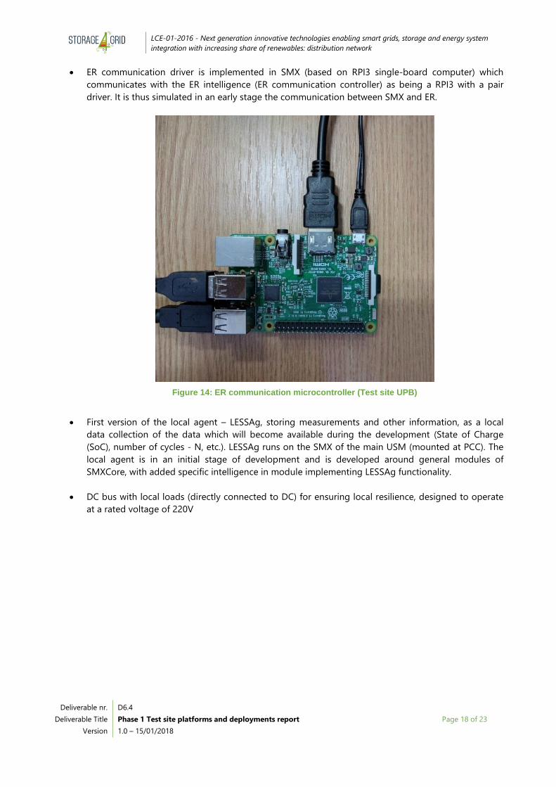
ER communication driver is implemented in SMX (based on RPI3 single-board computer) which
communicates with the ER intelligence (ER communication controller) as being a RPI3 with a pair
driver. It is thus simulated in an early stage the communication between SMX and ER.
Figure 14: ER communication microcontroller (Test site UPB)
First version of the local agent – LESSAg, storing measurements and other information, as a local
data collection of the data which will become available during the development (State of Charge
(SoC), number of cycles - N, etc.). LESSAg runs on the SMX of the main USM (mounted at PCC). The
local agent is in an initial stage of development and is developed around general modules of
SMXCore, with added specific intelligence in module implementing LESSAg functionality.
DC bus with local loads (directly connected to DC) for ensuring local resilience, designed to operate
at a rated voltage of 220V

LCE-01-2016 - Next generation innovative technologies enabling smart grids, storage and energy system
integration with increasing share of renewables: distribution network
Deliverable nr.
Deliverable Title
Version
D6.4
Phase 1 Test site platforms and deployments report
1.0 – 15/01/2018
Page 19 of 23
a)
b)
Figure 15: a) DC bus with local loads and b) DC plugs (Test site UPB)
Neighbor laboratory where an additional DC bus (rated voltage: 400 V) will supply loads appropriate
for being supplied in DC (approximately 300m from primary laboratory)
Figure 16: Neighbor laboratory to host the second DC bus (Test site UPB)

LCE-01-2016 - Next generation innovative technologies enabling smart grids, storage and energy system
integration with increasing share of renewables: distribution network
Deliverable nr.
Deliverable Title
Version
D6.4
Phase 1 Test site platforms and deployments report
1.0 – 15/01/2018
Page 20 of 23
Subcomponents to be used in modules for transmitting energy in DC between the main laboratory
and the neighbor laboratory
Figure 17: Subcomponents for DC-DC busses conversion (Test site UPB)
In the first phase, the UPB test site will focus on the scenario HLUC - 1 - PUC – 2, where the prosumer (ASRP)
is only operating as a load (consuming as much as possible from its locally produced RES-based electricity)
and will not back-generate surplus electricity. This will be accomplished based on the optimal management
of all components or actors implicated: ER, PV panels, batteries, DC loads, and AC loads. The energy
management will be implemented in such a way that the energy consumed (Pconsumed) from the DSO will
always be either null or higher than zero (≥0). The use case HLUC - 1 - PUC – 2 will be emulated in a
numerical program for a set of variables emulating 24 hours of operation (96 intervals of 15 minutes).
4.2 Problems faced and lessons learnt
As being in preparations for a first setup, a first problem has been related to the DC connection between the
two laboratories. The team is working to find appropriate pathways for the DC connection on a distance of
around 300 meters, such that it does not disturb communication cables and can be easier mounted. Lessons
learned will follow based on the solutions which will allow proper transmission of power while not disturbing
other activities. Approval has to be obtained from two different administrations, which has required an
additional effort.
A second problem that our team faced in the initial activities concerning the test site deployments consisted
in the grid event resulting in a overvoltage at the connectors of the existing PV installation, which destroyed
some protection components of the Steca charge controlle; therefore, after investigating the PV system, the
faulty components had to be changed. The team considers adding an overvoltage protection between the PV
panels and the subsequent elements (power electronics / router).
A third problem was related to the voltage of battery system, which is now 48 V (four 12 V batteries in series)
and need to be doubled, such that the DC-DC convertor voltage between the local DC bus and batteries are
in an adequate ratio for the intended operation, meaning less than 3 : 1. This requires additional four
batteries to be connected in series, in order to obtain the 96 V DC, which should allow a more efficient
connection to the DC bus.

LCE-01-2016 - Next generation innovative technologies enabling smart grids, storage and energy system
integration with increasing share of renewables: distribution network
Deliverable nr.
Deliverable Title
Version
D6.4
Phase 1 Test site platforms and deployments report
1.0 – 15/01/2018
Page 21 of 23
4.3 Testing plans
In this stage of the test site UPB will collect active (P), voltage (U) and currents (I) from the main USM meter,
but also will simulate acquisition of State of Charge (SoC) from the batteries and power (P) from the PV,
through the communication with a ER intelligence (RPI3 platform), similar with the one which will be used in
the ER.
This data will be used for local functionalities tested by LESSAg in the system, with simulated environment
(GESSCON and any other external component are simulated, until they will be available to communicate
directly with them)
4.4 Next steps towards Phase 2
In the phase 2 in Bucharest test site the focus will be on the complete integration of the components,
inclusive ER and the DC connection (400 V) between the 2 laboratories. Another 4 batteries will be also
integrated in the actual system, such that a more suitable voltage ratio is obtained between the DC bus of
the first laboratory and the battery pack.
LCE-01-2016 - Next generation innovative technologies enabling smart grids, storage and energy system
integration with increasing share of renewables: distribution network
Deliverable nr.
Deliverable Title
Version
D6.4
Phase 1 Test site platforms and deployments report
1.0 – 15/01/2018
Page 22 of 23
Acronyms
Acronym Explanation
AC Alternative Current
ASRP Advanced prosumer
DC Direct Current
ER Energy Router
LESSAg Local ESS control Agent
MQTT Message Queuing Telemetry Transport
PCC Point of Common Coupling
PV Photovoltaics
RPI3 Raspberry Pi 3
SMX Smart Meter eXtensions
SoC State of Charge
VRLA Valve-Regulated Lead-Acid
LCE-01-2016 - Next generation innovative technologies enabling smart grids, storage and energy system
integration with increasing share of renewables: distribution network
Deliverable nr.
Deliverable Title
Version
D6.4
Phase 1 Test site platforms and deployments report
1.0 – 15/01/2018
Page 23 of 23
List of figures
Figure 1: Test site for the residential case (Bolzano test site) ............................................................................................................................. 6
Figure 2: Wiring diagram of the PV roof plant (Bolzano test site) .................................................................................................................... 7
Figure 3: Plug for the EV charging (Bolzano test site) ............................................................................................................................................ 8
Figure 4: Inverter Fronius Symo Hybrid (Bolzano test site) .................................................................................................................................. 9
Figure 5: The new charging station ................................................................................................................................................................................ 9
Figure 6: Wiring diagram with Edyna meters (Bolzano test site) ..................................................................................................................... 10
Figure 7: Edyna garage, the test site with the charging stations installed .................................................................................................. 11
Figure 8: PV modules; Electrical switchboard with Fronius Smart Meter, Fronius inverter, Fronius battery (Test site Fur) .... 13
Figure 9: SMX box and details of SMX (Test site UPB) ......................................................................................................................................... 15
Figure 10: Landys+Gyr meter (a) uninstalled and (b) installed and connected to a Raspberry PI (Test site UPB) ..................... 16
Figure 11: PV panels (UPB Electrical Engineering Faculty rooftop) (Test site UPB) .................................................................................. 16
Figure 12: VRLA battery (Test site UPB) ...................................................................................................................................................................... 17
Figure 13: Steca Tarom hybrid charge controller (Test site UPB) .................................................................................................................... 17
Figure 14: ER communication microcontroller (Test site UPB) ......................................................................................................................... 18
Figure 15: a) DC bus with local loads and b) DC plugs (Test site UPB) ......................................................................................................... 19
Figure 16: Neighbor laboratory to host the second DC bus (Test site UPB) .............................................................................................. 19
Figure 17: Subcomponents for DC-DC busses conversion (Test site UPB) ................................................................................................. 20