d-303222 powermaster-10/30 g2 installer's guide · 1. introduction 4 d-303222...
TRANSCRIPT

www.visonic.com
PowerMaster-10 G2INSTALLER GUIDE
Fully supervised wireless alarm control system
D-303222 PowerMaster-10/30 G2 Installer's Guide 1
PowerMaster-10/30 G2
Version 16
Installer's Guide
Table of Contents
1. INTRODUCTION ................................................... 3 1.1 System Features ............................................ 3
2. CHOOSING THE INSTALLATION LOCATION ... 7
3. POWERMASTER-10 G2 INSTALLATION ........... 8 3.1 Opening the PowerMaster-10 G2 Control
Panel and Bracket Mounting .............................. 8 3.2 Connecting to the Telephone Line ............... 9 3.3 System Planning & Programming .............. 10 3.4 GSM Module Installation ............................. 10 3.5 PGM-5 Installation ....................................... 11 3.6 Adding Wired Zones or PGM Device ......... 12 3.7 Connecting Power to the Control Panel .... 13 3.8 Supplying Power to the Unit ....................... 16 3.9 Closing the PowerMaster-10 G2 Control
Panel ................................................................... 16
4. POWERMASTER-30 G2 INSTALLATION ......... 17 4.1 PowerMaster-30 G2 Wiring Diagram .......... 17 4.2 Opening the PowerMaster-30 G2 Control
Panel and Bracket Mounting ............................ 18 4.3 Connecting to the Telephone Line (detail
"M" in Figure 4.1) ............................................... 18 4.4 Connecting Wired Zone and Siren (detail "B" in Figure 4.1)................................................ 19 4.5 System Planning & Programming .............. 19 4.6 GSM Module Installation (detail "N" in Figure 4.1) ........................................................... 20 4.7 DUAL RS-232 Optional Module Mounting
(detail "F" in Figure 4.1) .................................... 20 4.8 PGM-5 Installation (located instead of detail
"F" in Figure 4.1) ................................................ 21 4.9 Optional Expander Module (detail "K" in Figure 4.1) ........................................................... 22 4.10 Connecting Power to the Control Panel .. 24 4.11 Battery Insertion ........................................ 25 4.12 Supplying Power to the Unit ..................... 25 4.13 Closing the PowerMaster-30 G2 Control
Panel ................................................................... 26
5. PROGRAMMING ................................................ 27 5.1 General Guidance ....................................... 27
5.1.1 Navigation ........................................... 27 5.1.2 Feedback Sounds ............................... 27
5.2 Entering the "Installer Mode" and Selecting
a Menu Option ................................................... 27 5.2.1 Entering the "Installer Mode" if "User
Permit" is enabled ........................................ 28 5.2.2 Selecting options ................................ 28 5.2.3 Exiting the Installer Mode ................... 28
5.3 Setting Installer Codes ............................... 29 5.3.1 Identical Installer and Master Installer
Codes ........................................................... 29 5.4 Zones / Devices ........................................... 30
5.4.1 General Guidance & Zones/Devices
Menu Options............................................... 30 5.4.2 Adding New Wireless Devices or Wired
Sensors ........................................................ 30 5.4.3 Deleting a Device ................................ 34 5.4.4 Modifying or Reviewing a Device ....... 34 5.4.5 Replacing a Device ............................. 34 5.4.6 Defining Configuration Defaults for
"Device Settings" ......................................... 35 5.4.7 Updating Devices after Exiting Installer
Mode ............................................................ 36 5.5 Control Panel ............................................... 36
5.5.1 General Guidance – "Control Panel"
Flow-Chart & Menu Options ........................ 36 5.5.2 Configuring Arming/Disarming and
Exit/Entry Procedures .................................. 37 5.5.3 Configuring Zones Functionality ......... 38 5.5.4 Configuring Alarms & Troubles ........... 39 5.5.5 Configuring Sirens Functionality ......... 40 5.5.6 Configuring Audible & Visual User
Interface ....................................................... 41 5.5.7 Configuring Jamming and Supervision
(Missing device) ........................................... 42 5.5.8 Configuring Miscellaneous Features .. 43
5.6 Communication ........................................... 43

2 D-303222 PowerMaster-10/30 G2 Installer's Guide
5.6.1 General Guidance – "Communication"
Flow-Chart & Menu Options ........................... 43 5.6.2 Configuring PSTN (landline phone)
Connection ................................................... 45 5.6.3 Configuring GSM-GPRS (IP) - SMS
Cellular Connection ...................................... 45 5.6.4 Configuring Events Reporting to
Monitoring Stations ....................................... 47 5.6.5 Configuring Events Reporting to Private
Users ............................................................ 51 5.6.6 Configuring Motion Cameras for Visual
Alarm Verification ......................................... 51 5.6.7 Configuring Upload / Download Remote
Programming Access Permission ................ 52 5.7 PGM Output .................................................. 53
5.7.1 General Guidance ............................... 53 5.7.2 Open Collector States ......................... 53 5.7.3 Configuring a PGM device .................. 53 5.7.4 Entering Daytime Limits ...................... 53 5.7.5 PGM Output Configuration .................. 54
5.8 Custom Names ............................................. 54 5.8.1 Custom Zone Names .......................... 54 5.8.2 Record Speech .................................... 55 5.8.3 Voice Box Mode
1 ................................. 56
5.9 Diagnostics .................................................. 56 5.9.1 General Guidance – "Diagnostics" Flow-
Chart & Menu Options .................................. 56 5.9.2 Testing Wireless Devices .................... 56 5.9.3 Testing the GSM module ..................... 57
5.10 User Settings .............................................. 58 5.11 Factory Default ........................................... 58 5.12 Serial Number ............................................ 58 5.13 Start UL/DL ................................................. 59 5.14 Partitioning ................................................. 59
5.14.1 General Guidance – "Partitioning"
Menu ............................................................. 59 5.14.2 Enabling / Disabling Partitions .......... 59
5.15 Operation Mode ......................................... 59 5.15.1 General Guidance – "Operation Mode"
Menu ............................................................. 59 5.15.2 Select between EN-50131, DD243 and
BS8243 ......................................................... 60 5.15.3 BS8243 Setup ................................... 60 5.15.4 DD243 Setup ..................................... 61
6. PERIODIC TEST ................................................. 62 6.1 General Guidance ........................................ 62 6.2 Conducting a Periodic Test ........................ 63
7. MAINTENANCE .................................................. 65 7.1 Handling System Troubles ......................... 65 7.2 Dismounting the Control Panel .................. 66
7.3 Replacing the Backup Battery ................... 66 7.4 Fuse Replacement ...................................... 66 7.5 Replacing/Relocating Detectors ................ 66 7.6 Annual System Check ................................ 67
8. READING THE EVENT LOG ............................. 67
APPENDIX A. Specifications ............................... 68 A1. Functional ................................................... 68 A2. Wireless ....................................................... 69 A3. Electrical...................................................... 69 A4. Communication .......................................... 70 A5. Physical Properties .................................... 70 A6. Peripherals and Accessory Devices ........ 71
APPENDIX B. Working with Partitions ............... 71 B1. User Interface and Operation .................... 71 B2. Common Areas ........................................... 72
APPENDIX C. Detector Deployment & Transmitter Assignments ......................................................... 72
C1. Detector Deployment Plan ........................ 72 C2. Keyfob Transmitter List ............................. 74 C3. Emergency Transmitter List ...................... 74 C4. Non-Alarm Transmitter List ....................... 74
APPENDIX D. Event Codes .................................. 74 D1. Contact ID Event Codes............................. 74 D2. SIA Event Codes ......................................... 75 D3. Understanding the Scancom Reporting Protocol Data Format ....................................... 76 D4. SIA over IP - Offset for Device User ......... 76
APPENDIX E. Sabbath Mode ............................... 76 E1. General Guidance ....................................... 76 E2. Connection .................................................. 76 E3. Arming the System by Sabbath Clock ..... 77
APPENDIX F. Glossary ......................................... 77
APPENDIX G. Compliance with Standards.......... 79
1. INTRODUCTION
D-303222 PowerMaster-10/30 G2 Installer's Guide 3
1. INTRODUCTION PowerMaster-10 G2 and PowerMaster-30 G2 are PowerG-enabled professional all-in-one wireless security, fire and
safety systems supporting advanced applications and Visonic's new revolutionary PowerG™ Two-Way, Time Division
Multiple Access (TDMA) and Frequency Hopping Spread Spectrum (FHSS) wireless technology. This offers unmatched
wireless robustness, superior range and long battery life; a perfect and user friendly solution for both monitoring service
providers and professional installers.
This manual refers to PowerMaster-10/30 G2 v16 and above. The most updated manuals can be downloaded from the
Visonic Web site http://www.visonic.com.
Note: For UL installations, please contact the manufacturer for the most recent version of UL approved documentation.
Note: "Pmaster" is used as an abbreviation for "PowerMaster".
The PowerMaster-10/30 G2 control panel is supplied with 2 instruction manuals:
Installer's Guide (this manual) – for use of system installer during system installation and configuration
User’s Guide -– also for use of system installer during system installation and configuration, but also for the master
user of the system, once installation is completed. Hand over this manual to the master user of the system.
1.1 System Features
The following table lists the PowerMaster features with a description of each feature and how to use it.
Feature Description How to configure and use
Visual Alarm
Verification
The PowerMaster when used with Next CAM
PG2 PIR-camera detector and GPRS
communication is able to provide the
Monitoring Station with clips captured in
alarm situations. The system sends the clips
to the Monitoring Station automatically for
burglary alarms and, depending on setup,
also for fire and personal emergency alarms.
Note: PowerMaster-10 G2 / PowerMaster-30
G2 are compatible with the following UL/ULC
listed receivers: SG-System I, SG-System III,
SG-System IV.
1. Setup GPRS communication: see GSM
Module Installation (section 3.4 for
PowerMaster-10 G2 or section 4.4 for
PowerMaster-30 G2)
2. Configure camera settings: refer to the
Next CAM PG2 Installation Instructions
3. Enable fire and personal alarm
verification: see section 5.6.6 Configuring
Motion Cameras for Video Alarm Verification
On demand clips from
cameras
The PowerMaster can provide images from
the Next CAM PG2 by demand from a
remote PowerManage server. Pictures are
taken based on a command from the
monitoring station. To protect customers'
privacy, the system can be customized to
enable the "On Demand View" only during
specific system modes (i.e. Disarm, Home &
Away) and also to a specific time window
following an alarm event.
1. Setup the On demand feature: see
section 5.6.6 Configuring Motion Cameras
for Video Alarm Verification
2. To request and view images: refer to the
PowerManage User's Guide, Chapter 5
Viewing and Handling Events
Easy Enrollment PowerG devices are enrolled from the control
panel. "Pre-enrollment" can also be
performed by entering the PowerG device ID
number and then activating the device in the
vicinity of the panel.
To enroll or pre-enroll devices: see section
5.4.2 Adding New Wireless Devices or Wired
Sensors
1. INTRODUCTION
4 D-303222 PowerMaster-10/30 G2 Installer's Guide
Device Configuration Device parameters and related system
behavior can be configured from the control
panel or from a remote location.
Each PowerG device has its own settings
which can be configured through the control
panel by entering the "DEVICE SETTINGS"
menu.
Note: The minimum configuration of the
system includes one detector.
To configure devices from the control
panel: see Chapter 5 Programming and also
the individual device's Installation
Instructions.
To configure devices from a remote
location: refer to the PowerManage User's
Guide Chapter 3 Working with Panels and to
the Remote Programmer PC software User's
Guide, Chapters 6 and 7.
Diagnostics of the
control panel and
peripherals
You can test the function of all wireless
sensors deployed throughout the protected
area, to collect information about the
received signal strength from each
transmitter and to review accumulated data
after the test.
To perform diagnostics and to obtain
signal strength indication: see section 5.9
Diagnostics
Conducting periodic
tests
The system should be tested at least once a
week and after an alarm. The periodic test
can be conducted locally or from a remote
location (with the assistance from a non-
technical person in the house).
To conduct a walk test locally: see
Chapter 6 Periodic Test
To conduct a walk test from remote
location: refer to the Remote Programmer
PC software User's Guide, Chapter 6 Data
Details Tables.
Partitions The partitioning feature, when enabled,
divides your alarm system into distinct areas
each of which operates as an individual
alarm system. Partitioning can be used in
installations where shared security systems
are more practical, such as a home office or
warehouse building.
1. Enable partitioning: see section 5.14
Partitioning
2. Setup partition association for each
device: see section 5.4.2 Adding New
Wireless Devices or Wired Sensors
To understand more about partitioning:
see APPENDIX B. Working with Partitions
and APPENDIX A. in the User's Guide.
Two-way voice
communication1
The PowerMaster system enables voice
communication with Monitoring Stations
To enable and configure two way voice:
see section 5.6.4 Configuring Events
Reporting to Monitoring Stations
Device configuration
templates
The default parameters with which a new
device is enrolled into the system can be set
before you enroll devices. This default
template saves time on device configuration.
1. Define enrollment defaults for devices:
see section 5.4.6 Defining Configuration
Defaults for "Device Settings"
2. Enroll or pre-enroll devices: see section
5.4.2 Adding New Wireless Devices or Wired
Sensors
SirenNet - distributed
siren using Smoke
detectors
All PowerG smoke detectors are able to
function as sirens, alerting on any of 4 types of
alarm in the system: fire, gas, burglary and
flood.
Enable and configure SirenNet for each
smoke detector: refer to the SMD-426 PG2
/ SMD-427 PG2 Installation Instructions
Integrated Siren built
into the panel
The control panel has a high-powered built-in
siren that sounds in case of alarm, enabled by
default.
To define whether or not the control
panel's siren will sound upon alarms: see
section 5.5.5 Configuring Sirens Functionality
Wired Siren outputs The control panel can operate a wired siren
and strobe devices
Install and connect wired siren: see
section 4.7 Optional Expander Module
Mounting
1 Refers to PowerMaster-30 G2 with voice option only
1. INTRODUCTION
D-303222 PowerMaster-10/30 G2 Installer's Guide 5
Wired zones and
programmable
outputs (PGM)
The control panel can support wired detectors
and control automation devices with
programmable wired outputs.
1. Connect a wired zone or PGM device:
see section 3.6 Adding a Wired Zone or
PGM.
2. Program the wired zone: see section
5.4.2 Adding New Wireless Devices or Wired
Sensors
3. Program PGM outputs behavior: see
section 5.7 PGM Output.
Reporting to Private
Users and/or
Monitoring Station by
telephone, SMS and
IP communication
The PowerMaster system can be
programmed to send notifications of alarm
and other events to 4 private telephone
subscribers by voice and also to 4 SMS
cellular phone numbers and to report these
events to the Monitoring Station by SMS,
PSTN or IP communication
(IP communication not enabled in UL Listed
product).
To configure notifications to Private
phones: refer to the PowerMaster-10/30 G2
User's Guide, Chapter 6, section C.11
Programming Private Phone and SMS
Reporting
To configure reporting to the Montioring
Station: see section 5.6.4 Configuring
Events Reporting to Monitoring Stations
Quick installation with
link quality indication
With PowerG devices, there is no need to
consult the control panel when mounting a
wireless device, because PowerG devices
include a built-in link quality indicator.
Choosing the mounting location is a quick
and easy process.
To choose the ideal location to mount a
wireless device, see Chapter 2 Choosing the
Installation Location.
Device Locator Helps you to easily identify the actual device
displayed on the LCD display.
To read more on the Device Locator: refer
to the PowerMaster-10/30 G2 User's Guide,
Chapter 2, Operating the PowerMaster
System
To use the device locator when bypassing
a zone or when clearing a bypassed zone:
refer to the PowerMaster-10/30 G2 User's
Guide, Chapter 6, section C.1 Setting the
Zone Bypass Scheme
To use the device locator when
conducting the periodic test: see Chapter
6 Periodic Test or refer to the PowerMaster-
10/30 G2 User's Guide, Chapter 9 Testing
the System
Guard key-safe PowerMaster is able to control a safe that
holds site keys that are accessible only to the
site's guard or Monitoring Station's guard in
the event of an alarm.
1. Connect the safe to the panel: see
section 3.6 Adding Wired Zones or PGM
Device, Figure 3.6b (PowerMaster-10 G2) /
section 4.7 Optional Expander Module
Mounting, Figure 4.8b (PowerMaster-30 G2)
2. Configure the safe's zone type to
"Guard Zone": see section 5.4.2 Adding
New Wireless Devices or Wired Sensors
3. Setup guard code: see section 5.3
Setting Installer Codes
Arming Key External system may control arming and
disarming of the PowerMaster system
1. Connect the external system output to
the panel: see section 3.6 Adding Wired
Zones or PGM Device, Figure 3.6b
(PowerMaster-10 G2) / section 4.7 Optional
Expander Module Mounting, Figure 4.8b
(PowerMaster-30 G2)
Note: Monitoring Station means not evaluated by UL.

1. INTRODUCTION
6 D-303222 PowerMaster-10/30 G2 Installer's Guide
System Architecture:
Security Detectors and Transmitters
Main Control Panels
Keyfobs, Keypad and Keyprox
Next CAM PG2 Motion
Detector with Camera
Next PG2 Motion
Detector
MC-302 PG2
Magnetic
Contact
TOWER-30AM
PG2
Mirror Detector
PowerMaster-10 G2
PowerMaster-30 G2
KF-234 PG2
KF-235 PG2
Two-way Keyfobs
KP-140 PG2
Two-way Keypad
Safety Detectors
KP-160 PG2 Keyprox
SMD-426 PG2
Smoke Detector
SMD-427 PG2
Smoke & Heat
Detector
TMD-560 PG2
Temperature
Detector
GSD-441 PG2
Gas (Methane) Detector
GSD-442 PG2
Carbon Monoxide (CO)
Detector
FLD-550 PG2
Flood
Detector
Sirens
SR-730 PG2
Outdoor
Siren
SR-720 PG2
Indoor Siren
2. CHOOSING THE INSTALLATION LOCATION
D-303222 PowerMaster-10/30 G2 Installer's Guide 7
2. CHOOSING THE INSTALLATION LOCATION To ensure the best possible mounting location of the PowerMaster control panel, the following points should be
observed:
The selected location should be approximately in the center of the installation site between all the transmitters, preferably in a hidden location.
In close proximity to an AC source
In close proximity to a telephone line connection (if PSTN is used)
Where there is good cellular coverage, if GSM-350 PG2 is used
Far from sources of wireless interference, such as:
o Computers or other electronic devices, power conductors, cordless phones, light dimmers, etc.
o Large metal objects (such as metal doors or refrigerators)
Note: A distance of at least 1 meter (3 ft) is recommended.
If using the panel's built-in siren and/or voice, select location where audio can be heard throughout the premises.
When mounting wireless devices:
Make sure that the signal reception level for each device is either "Strong" or "Good", but not "Poor".
Note: For UL/cUL installations, the test result must be "Strong" for all wireless devices.
Wireless magnetic contacts should be installed in a vertical position and as high up the door or window as possible.
Wireless PIR detectors should be installed upright at the height specified in their Installation Instructions
Repeaters should be located high on the wall in mid-distance between the transmitters and the control panel.
WARNING! To comply with FCC and IC RF exposure compliance requirements, the control panel should be located at a distance of at least 20 cm from all persons during normal operation. The antennas used for this product must not be co-located or operated in conjunction with any other antenna or transmitter.
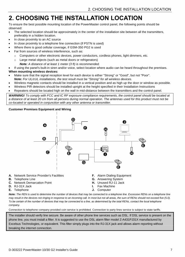
Customer Premises Equipment and Wiring
A
B
C
D
E
F
G
H
I
E
E
H
J
A. Network Service Provider's Facilities F. Alarm Dialing Equipment B. Telephone Line G. Answering System C. Network Demarcation Point H. Unused RJ-11 Jack D. RJ-31X Jack I. Fax Machine E. Telephone J. Computer
Note: The REN is used to determine the number of devices that may be connected to a telephone line. Excessive RENs on a telephone line
may result in the devices not ringing in response to an incoming call. In most but not all areas, the sum of RENs should not exceed five (5.0).
To be certain of the number of devices that may be connected to a line, as determined by the total RENs, contact the local telephone
company.
Connection to telephone company provided coin service is prohibited. Connection to party lines service is subject to state tariffs.
The installer should verify line seizure. Be aware of other phone line services such as DSL. If DSL service is present on the
phone line, you must install a filter. It is suggested to use the DSL alarm filter model Z-A431PJ31X manufactured by
Excelsus Technologies, or equivalent. This filter simply plugs into the RJ-31X jack and allows alarm reporting without
breaking the internet connection.
3. POWERMASTER-10 G2 INSTALLATION
8 D-303222 PowerMaster-10/30 G2 Installer's Guide
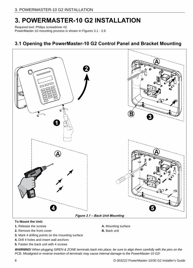
3. POWERMASTER-10 G2 INSTALLATION Required tool: Philips screwdriver #2. PowerMaster-10 mounting process is shown in Figures 3.1 - 3.9.
3.1 Opening the PowerMaster-10 G2 Control Panel and Bracket Mounting
Figure 3.1 – Back Unit Mounting
To Mount the Unit:
1. Release the screws A. Mounting surface
2. Remove the front cover B. Back unit
3. Mark 4 drilling points on the mounting surface
4. Drill 4 holes and insert wall anchors
5. Fasten the back unit with 4 screws
WARNING! When plugging SIREN & ZONE terminals back into place, be sure to align them carefully with the pins on the
PCB. Misaligned or reverse insertion of terminals may cause internal damage to the PowerMaster-10 G2!
3. POWERMASTER-10 G2 INSTALLATION
D-303222 PowerMaster-10/30 G2 Installer's Guide 9
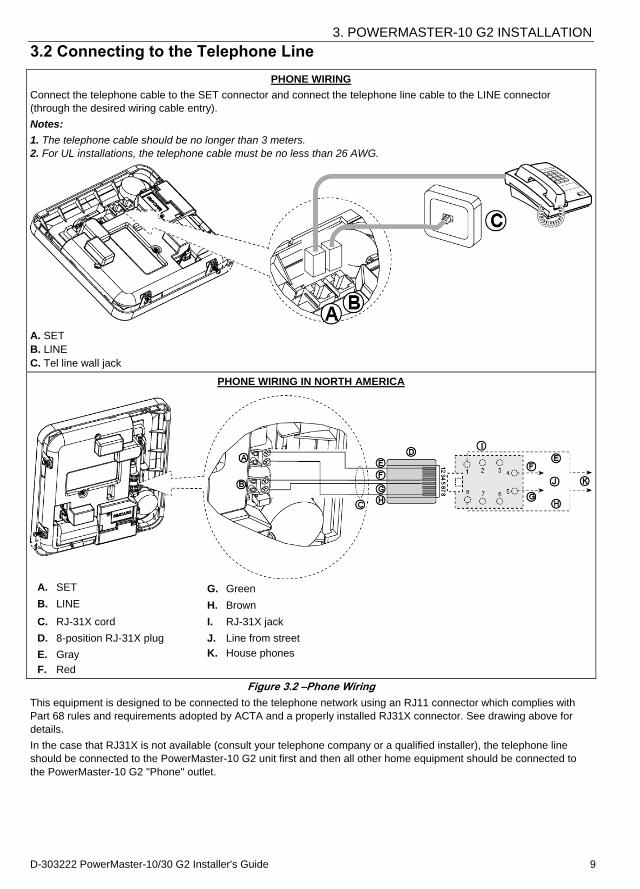
3.2 Connecting to the Telephone Line
PHONE WIRING
Connect the telephone cable to the SET connector and connect the telephone line cable to the LINE connector
(through the desired wiring cable entry).
Notes:
1. The telephone cable should be no longer than 3 meters.
2. For UL installations, the telephone cable must be no less than 26 AWG.
A. SET
B. LINE
C. Tel line wall jack
PHONE WIRING IN NORTH AMERICA
A. SET G. Green
B. LINE H. Brown
C. RJ-31X cord I. RJ-31X jack
D. 8-position RJ-31X plug J. Line from street
E. Gray K. House phones
F. Red
Figure 3.2 –Phone Wiring
This equipment is designed to be connected to the telephone network using an RJ11 connector which complies with
Part 68 rules and requirements adopted by ACTA and a properly installed RJ31X connector. See drawing above for
details.
In the case that RJ31X is not available (consult your telephone company or a qualified installer), the telephone line
should be connected to the PowerMaster-10 G2 unit first and then all other home equipment should be connected to
the PowerMaster-10 G2 "Phone" outlet.

3. POWERMASTER-10 G2 INSTALLATION
10 D-303222 PowerMaster-10/30 G2 Installer's Guide
3.3 System Planning & Programming
Program the system now as instructed in the programming section.
The tables in APPENDIX C will help you plan and record location of each detector, the holder and assignment of each
transmitter.
3.4 GSM Module Installation
The internal GSM 350 module enables the PowerMaster-10 G2 system to operate over a GSM/GPRS cellular network (for further details, see the GSM 350 PG2 Installation Instructions).
The GSM modem auto detection feature enables automatic enrollment of the GSM modem into the PowerMaster-10 G2 control panel memory. GSM modem auto detection is activated in one of two ways: after tamper restore and after reset (power-up or after exiting the installer menu). This causes the PowerMaster-10 G2 to automatically scan GSM COM ports for the presence of the GSM modem.
In the event that the GSM modem auto detection fails and the modem was previously enrolled in the PowerMaster-10
G2 control panel, the message "Cel Remvd Cnfrm" will be displayed. This message will disappear from the display only
after the user presses the button. The modem is then considered as not enrolled and no GSM trouble message will be displayed. Notes:
1) A message is displayed only when the PowerMaster-10 G2 alarm system is disarmed.
2) The GSM Alarm Transmission System compliance with EN 50131-1 ATS4 was proven by testing the signaling security requirements D2, M2, T3, S1, I2” detailed in EN 50136-1-1:1998/A2: 2008, EN 50136-2-1:1998/A1: 2001, EN50136-2-2: 1998.
Plug in the GSM module and fasten it as shown in the
above drawing.
A. GSM
B. Front unit
Caution! Disconnect both batteries and AC power before
installing or removing the GSM module or SIM card.
Insert the SIM card into the GSM module as shown in the
above drawing.
1. Slide top cover.
2. Open cover
3. Align SIM card in cover (note cover orientation)
4. Slide SIM card into cover
5. Rotate cover to close
6. Lock cover to close
IMPORTANT! Do not insert or remove SIM card when the
control panel is powered by AC power or battery.
Figure 3.4 – Optional GSM Module Mounting and SIM Card Insertion
3. POWERMASTER-10 G2 INSTALLATION
D-303222 PowerMaster-10/30 G2 Installer's Guide 11
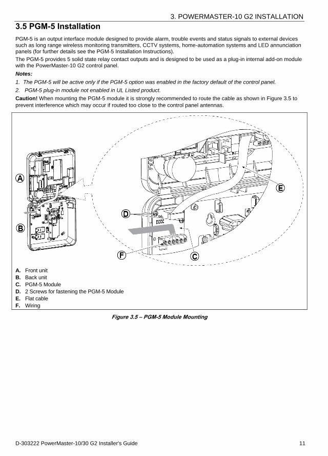
3.5 PGM-5 Installation
PGM-5 is an output interface module designed to provide alarm, trouble events and status signals to external devices such as long range wireless monitoring transmitters, CCTV systems, home-automation systems and LED annunciation panels (for further details see the PGM-5 Installation Instructions).
The PGM-5 provides 5 solid state relay contact outputs and is designed to be used as a plug-in internal add-on module with the PowerMaster-10 G2 control panel.
Notes:
1. The PGM-5 will be active only if the PGM-5 option was enabled in the factory default of the control panel.
2. PGM-5 plug-in module not enabled in UL Listed product.
Caution! When mounting the PGM-5 module it is strongly recommended to route the cable as shown in Figure 3.5 to
prevent interference which may occur if routed too close to the control panel antennas.
A. Front unit
B. Back unit
C. PGM-5 Module
D. 2 Screws for fastening the PGM-5 Module
E. Flat cable
F. Wiring
Figure 3.5 – PGM-5 Module Mounting
3. POWERMASTER-10 G2 INSTALLATION
12 D-303222 PowerMaster-10/30 G2 Installer's Guide
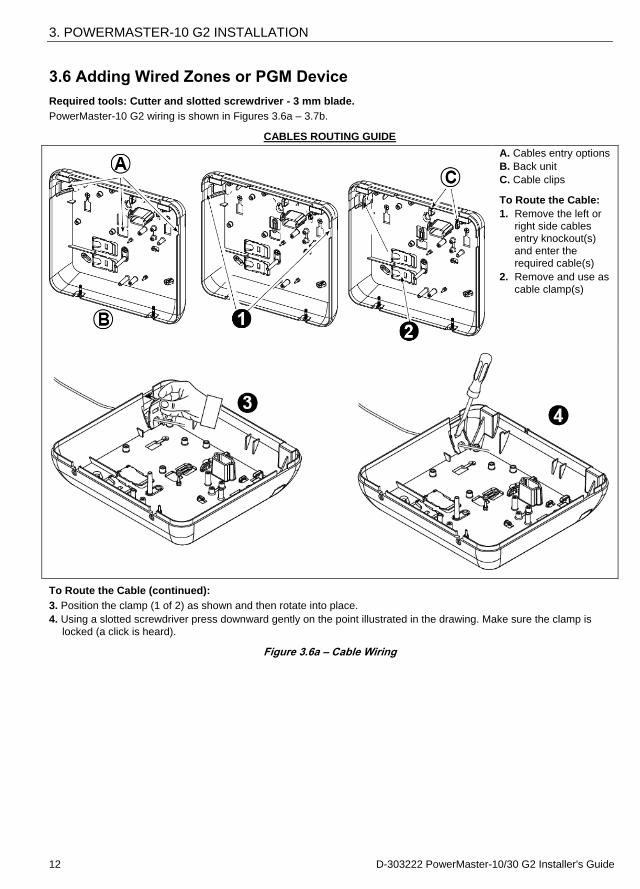
3.6 Adding Wired Zones or PGM Device
Required tools: Cutter and slotted screwdriver - 3 mm blade.
PowerMaster-10 G2 wiring is shown in Figures 3.6a – 3.7b.
CABLES ROUTING GUIDE
A. Cables entry options
B. Back unit
C. Cable clips
To Route the Cable:
1. Remove the left or right side cables entry knockout(s) and enter the required cable(s)
2. Remove and use as
cable clamp(s)
To Route the Cable (continued):
3. Position the clamp (1 of 2) as shown and then rotate into place.
4. Using a slotted screwdriver press downward gently on the point illustrated in the drawing. Make sure the clamp is
locked (a click is heard).
Figure 3.6a – Cable Wiring
3. POWERMASTER-10 G2 INSTALLATION
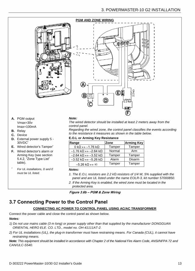
D-303222 PowerMaster-10/30 G2 Installer's Guide 13
PGM AND ZONE WIRING
A. PGM output
Vmax=30v
Imax=100mA
B. Relay
C. Device
D. External power supply 5 - 30VDC
E. Wired detector's Tamper
F. Wired detector's alarm or Arming Key (see section 5.4.2, “Zone Type List” table).
For UL installations, D and E
must be UL listed.
Note: The wired detector should be installed at least 2 meters away from the control panel. Regarding the wired zone, the control panel classifies the events according to the resistance it measures as shown in the table below.
E.O.L or Arming Key Resistance
Range Zone Arming Key
0 kΩ 1.76 kΩ Tamper Tamper
1.76 kΩ 2.64 kΩ Normal Arm
2.64 kΩ 3.52 kΩ Tamper Tamper
3.52 kΩ 5.26 kΩ Alarm Disarm
5.26 kΩ ∞ Tamper Tamper
Notes:
1. The E.O.L resistors are 2.2 kΩ resistors of 1/4 W, 5% supplied with the panel and are UL listed under the name EOLR-3, kit number 57000850.
2. If the Arming Key is enabled, the wired zone must be located in the protected area.
Figure 3.6b – PGM & Zone Wiring
3.7 Connecting Power to the Control Panel
CONNECTING AC POWER TO CONTROL PANEL USING AC/AC TRANSFORMER
Connect the power cable and close the control panel as shown below.
Notes:
1) Do not use mains cable (3 m long) or power supply other than that supplied by the manufacturer DONGGUAN
ORIENTAL HERO ELE. CO. LTD., model no. OH-41111AT-2.
2) For UL installations (UL), the plug-in transformer must have restraining means. For Canada (CUL), it cannot have
restraining means.
Note: This equipment should be installed in accordance with Chapter 2 of the National Fire Alarm Code, ANSI/NFPA 72 and
CAN/ULC-S540.
3. POWERMASTER-10 G2 INSTALLATION
14 D-303222 PowerMaster-10/30 G2 Installer's Guide
Notes for UL installations:
1. A device that is connected to PGM terminal should not be programmed to be activated during standby.
2. The system shall be installed in accordance with CSA C22.1 Canadian Electrical Code, Part 1.
3. A minimum spacing of 1/4 inch shall be maintained between the telephone wiring and the low voltage wiring (zones,
bell circuit, etc.). Do not route the LINE and SET wires in the same wiring channel with other wires.
4. Do not connect to a receptacle controlled by a switch.
5. Hard wired zones are for BURG use only.
6 Tamper (E) and external power supply (D) must be UL Listed.
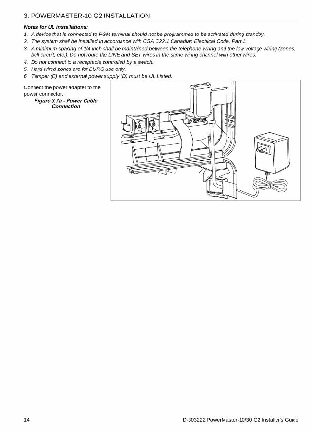
Connect the power adapter to the
power connector.
Figure 3.7a - Power Cable Connection
3. POWERMASTER-10 G2 INSTALLATION
D-303222 PowerMaster-10/30 G2 Installer's Guide 15
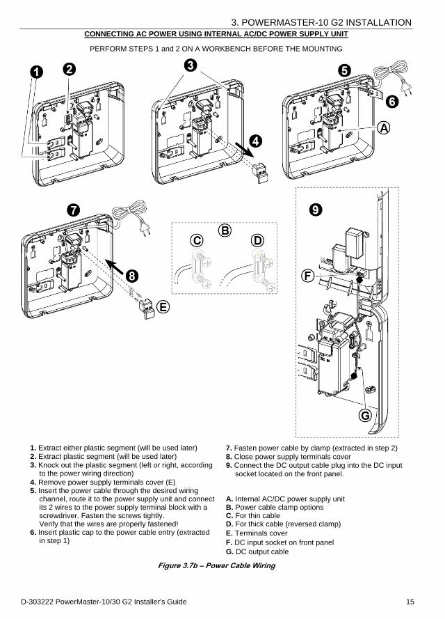
CONNECTING AC POWER USING INTERNAL AC/DC POWER SUPPLY UNIT
PERFORM STEPS 1 and 2 ON A WORKBENCH BEFORE THE MOUNTING
1. Extract either plastic segment (will be used later) 7. Fasten power cable by clamp (extracted in step 2) 2. Extract plastic segment (will be used later) 8. Close power supply terminals cover 3. Knock out the plastic segment (left or right, according
to the power wiring direction) 9. Connect the DC output cable plug into the DC input
socket located on the front panel. 4. Remove power supply terminals cover (E)
A. Internal AC/DC power supply unit B. Power cable clamp options C. For thin cable D. For thick cable (reversed clamp)
E. Terminals cover
F. DC input socket on front panel
G. DC output cable
5. Insert the power cable through the desired wiring channel, route it to the power supply unit and connect its 2 wires to the power supply terminal block with a screwdriver. Fasten the screws tightly. Verify that the wires are properly fastened!
6. Insert plastic cap to the power cable entry (extracted in step 1)
Figure 3.7b – Power Cable Wiring
3. POWERMASTER-10 G2 INSTALLATION
16 D-303222 PowerMaster-10/30 G2 Installer's Guide
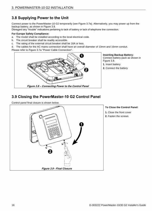
3.8 Supplying Power to the Unit
Connect power to the PowerMaster-10 G2 temporarily (see Figure 3.7a). Alternatively, you may power up from the backup battery, as shown in Figure 3.8. Disregard any “trouble” indications pertaining to lack of battery or lack of telephone line connection.
For Europe Safety Compliance:
a. The model shall be installed according to the local electrical code.
b. The circuit breaker shall be readily accessible.
c. The rating of the external circuit breaker shall be 16A or less.
d. The cables for the AC mains connection shall have an overall diameter of 13mm and 16mm conduit.
Please refer to Figure 3.7a "Power Cable Connection".
Figure 3.8 – Connecting Power to the Control Panel
Inserting Backup Battery: Connect battery pack as shown in Figure 3.8.
1. Insert battery
2. Connect the battery
3.9 Closing the PowerMaster-10 G2 Control Panel
Control panel final closure is shown below.
Figure 3.9 - Final Closure
To Close the Control Panel:
1. Close the front cover
2. Fasten the screws
4. POWERMASTER-30 G2 INSTALLATION
D-303222 PowerMaster-10/30 G2 Installer's Guide 17
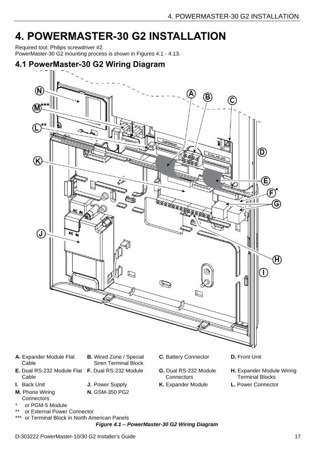
4. POWERMASTER-30 G2 INSTALLATION Required tool: Philips screwdriver #2. PowerMaster-30 G2 mounting process is shown in Figures 4.1 - 4.13.
4.1 PowerMaster-30 G2 Wiring Diagram
A. Expander Module Flat Cable
B. Wired Zone / Special Siren Terminal Block
C. Battery Connector D. Front Unit
E. Dual RS-232 Module Flat
Cable
F. Dual RS-232 Module G. Dual RS-232 Module
Connectors
H. Expander Module Wiring
Terminal Blocks
I. Back Unit J. Power Supply K. Expander Module L. Power Connector
M. Phone Wiring Connectors
N. GSM-350 PG2
* or PGM-5 Module
** or External Power Connector *** or Terminal Block in North American Panels
Figure 4.1 – PowerMaster-30 G2 Wiring Diagram
4. POWERMASTER-30 G2 INSTALLATION
18 D-303222 PowerMaster-10/30 G2 Installer's Guide
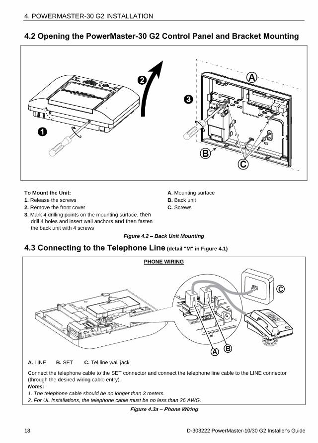
4.2 Opening the PowerMaster-30 G2 Control Panel and Bracket Mounting
To Mount the Unit:
1. Release the screws
2. Remove the front cover
3. Mark 4 drilling points on the mounting surface, then drill 4 holes and insert wall anchors and then fasten
the back unit with 4 screws
A. Mounting surface
B. Back unit
C. Screws
Figure 4.2 – Back Unit Mounting
4.3 Connecting to the Telephone Line (detail "M" in Figure 4.1)
PHONE WIRING
A. LINE B. SET C. Tel line wall jack
Connect the telephone cable to the SET connector and connect the telephone line cable to the LINE connector
(through the desired wiring cable entry).
Notes:
1. The telephone cable should be no longer than 3 meters.
2. For UL installations, the telephone cable must be no less than 26 AWG.
Figure 4.3a – Phone Wiring
4. POWERMASTER-30 G2 INSTALLATION
D-303222 PowerMaster-10/30 G2 Installer's Guide 19
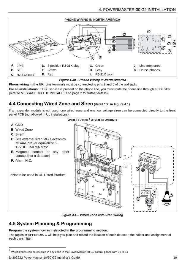
PHONE WIRING IN NORTH AMERICA
A. LINE
B. SET
C. RJ-31X cord
D. 8-position RJ-31X plug
E. Brown
F. Red
G. Green
H. Gray
I. RJ-31X jack
J. Line from street
K. House phones
Figure 4.3b – Phone Wiring in North America
Phone wiring in the UK: Line terminals must be connected to pins 2 and 5 of the wall jack.
For all installations: If DSL service is present on the phone line, you must route the phone line through a DSL filter
(refer to MESSAGE TO THE INSTALLER on page 2 for further details).
4.4 Connecting Wired Zone and Siren (detail "B" in Figure 4.1)
If an expander module is not used, one wired zone and one low voltage siren can be connected directly to the front
panel PCB (not allowed in UL installations).
WIRED ZONE1 &SIREN WIRING
A. GND
B. Wired Zone
C. Siren*
D. Site external siren MG electronics
MG441PDS or equivalent 6-
12VDC, 150 mA Max*
E. Magnetic contact or any other
contact (not a detector)
F. Alarm N.C.
*Not to be used in UL Listed Product
Figure 4.4 – Wired Zone and Siren Wiring
4.5 System Planning & Programming
Program the system now as instructed in the programming section.
The tables in APPENDIX C will help you plan and record the location of each detector, the holder and assignment of each transmitter.
1 Wired zones can be enrolled in any zone in the PowerMaster-30 G2 control panel from 01 to 64
4. POWERMASTER-30 G2 INSTALLATION
20 D-303222 PowerMaster-10/30 G2 Installer's Guide
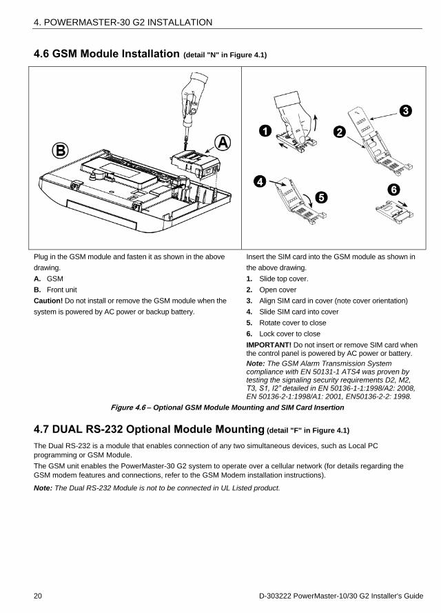
4.6 GSM Module Installation (detail "N" in Figure 4.1)
Plug in the GSM module and fasten it as shown in the above
drawing.
A. GSM
B. Front unit
Caution! Do not install or remove the GSM module when the
system is powered by AC power or backup battery.
Insert the SIM card into the GSM module as shown in
the above drawing.
1. Slide top cover.
2. Open cover
3. Align SIM card in cover (note cover orientation)
4. Slide SIM card into cover
5. Rotate cover to close
6. Lock cover to close
IMPORTANT! Do not insert or remove SIM card when the control panel is powered by AC power or battery.
Note: The GSM Alarm Transmission System compliance with EN 50131-1 ATS4 was proven by testing the signaling security requirements D2, M2, T3, S1, I2” detailed in EN 50136-1-1:1998/A2: 2008, EN 50136-2-1:1998/A1: 2001, EN50136-2-2: 1998.
Figure 4.6 – Optional GSM Module Mounting and SIM Card Insertion
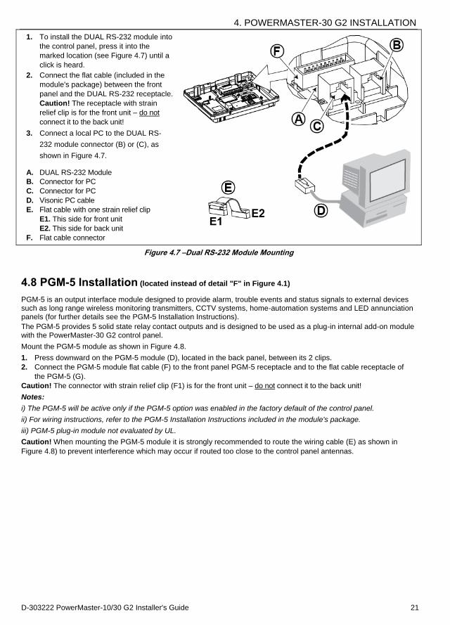
4.7 DUAL RS-232 Optional Module Mounting (detail "F" in Figure 4.1)
The Dual RS-232 is a module that enables connection of any two simultaneous devices, such as Local PC
programming or GSM Module.
The GSM unit enables the PowerMaster-30 G2 system to operate over a cellular network (for details regarding the
GSM modem features and connections, refer to the GSM Modem installation instructions).
Note: The Dual RS-232 Module is not to be connected in UL Listed product.
4. POWERMASTER-30 G2 INSTALLATION
D-303222 PowerMaster-10/30 G2 Installer's Guide 21
1. To install the DUAL RS-232 module into
the control panel, press it into the
marked location (see Figure 4.7) until a
click is heard.
2. Connect the flat cable (included in the
module's package) between the front
panel and the DUAL RS-232 receptacle.
Caution! The receptacle with strain
relief clip is for the front unit – do not
connect it to the back unit!
3. Connect a local PC to the DUAL RS-
232 module connector (B) or (C), as
shown in Figure 4.7.
A. DUAL RS-232 Module
B. Connector for PC
C. Connector for PC
D. Visonic PC cable
E. Flat cable with one strain relief clip
E1. This side for front unit
E2. This side for back unit
F. Flat cable connector
Figure 4.7 –Dual RS-232 Module Mounting
4.8 PGM-5 Installation (located instead of detail "F" in Figure 4.1)
PGM-5 is an output interface module designed to provide alarm, trouble events and status signals to external devices such as long range wireless monitoring transmitters, CCTV systems, home-automation systems and LED annunciation panels (for further details see the PGM-5 Installation Instructions).
The PGM-5 provides 5 solid state relay contact outputs and is designed to be used as a plug-in internal add-on module with the PowerMaster-30 G2 control panel.
Mount the PGM-5 module as shown in Figure 4.8.
1. Press downward on the PGM-5 module (D), located in the back panel, between its 2 clips.
2. Connect the PGM-5 module flat cable (F) to the front panel PGM-5 receptacle and to the flat cable receptacle of
the PGM-5 (G).
Caution! The connector with strain relief clip (F1) is for the front unit – do not connect it to the back unit!
Notes:
i) The PGM-5 will be active only if the PGM-5 option was enabled in the factory default of the control panel.
ii) For wiring instructions, refer to the PGM-5 Installation Instructions included in the module's package.
iii) PGM-5 plug-in module not evaluated by UL.
Caution! When mounting the PGM-5 module it is strongly recommended to route the wiring cable (E) as shown in
Figure 4.8) to prevent interference which may occur if routed too close to the control panel antennas.

4. POWERMASTER-30 G2 INSTALLATION
22 D-303222 PowerMaster-10/30 G2 Installer's Guide
A. PowerMaster-30 G2 connector
B. Front unit
C. PGM-5 Module
D. Back unit
E. Wiring Cable
F. Flat cable
F1. This side for front unit
F2. This side for back unit
G. PGM-5 flat cable receptacle
Figure 4.8 – PGM-5 Module Mounting
4.9 Optional Expander Module (detail "K" in Figure 4.1)
The Expander module is an optional module. If this optional module is used, the wired zone or special siren on the front panel should not be used.
Note: The optional Expander Module not to be connected in UL Listed product.
Mount the Expander module as shown in Figure 4.9a.
1. Press downward on the Expander module
(located in the back panel) between its 2
clips.
2. Connect the Expander module flat cable
to the front panel Expander receptacle.
Caution! The receptacle with strain relief
clip is for the front unit – do not connect it to
the back unit!
A. 2 clips
B. Flat cable with one strain relief clip
B1. This side for front unit
B2. This side for back unit
Figure 4.9a –Expander Module
4. POWERMASTER-30 G2 INSTALLATION
D-303222 PowerMaster-10/30 G2 Installer's Guide 23
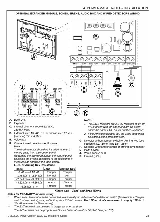
OPTIONAL EXPANDER MODULE, ZONES, SIRENS, AUDIO BOX AND WIRED DETECTORS WIRING
A. Back Unit
B. Expander
C. Internal siren or strobe 6-12 VDC,
150 mA Max.
D. External siren MG441PDS or similar siren 12 VDC (nominal) 350 mA Max.
E. Voice box
F. Connect wired detectors as illustrated. Note: The wired detector should be installed at least 2 meters away from the control panel. Regarding the two wired zones, the control panel classifies the events according to the resistance it measures as shown in the table below.
E.O.L or Arming Key Resistance
Range Zone Arming Key
0 kΩ 1.76 kΩ Tamper Tamper
1.76 kΩ 2.64 kΩ Normal Arm
2.64 kΩ 3.52 kΩ Tamper Tamper
3.52 kΩ 5.26 kΩ Alarm Disarm
5.26 kΩ ∞ Tamper Tamper
Notes:
1. The E.O.L resistors are 2.2 kΩ resistors of 1/4 W, 5% supplied with the panel and are UL listed under the name EOLR-3, kit number 57000850.
2. If the Arming enabled is set, the wired zone must
be located in the protected area.
G. Detector without tamper switch or Arming Key (see section 5.4.2, “Zone Type List” table).
H. Detector with tamper switch or arming key's tamper I. PGM device J. Wired zone A or B K. Ground (GND)
Figure 4.9b – Zone and Siren Wiring
Notes for EXPANDER module wiring: * Wired zone
terminals can be connected to a normally closed contact of a detector, switch (for example a Tamper
switch of any device), or a pushbutton, via a 2.2 K resistor. The 12V terminal can be used to supply 12V (up to 36mA) to a detector (if necessary).
** The EXT terminal can be used to trigger an external siren.
The INT terminal can be programmed for an "internal siren" or "strobe" (see par. 5.7).

4. POWERMASTER-30 G2 INSTALLATION
24 D-303222 PowerMaster-10/30 G2 Installer's Guide
The 12V and "GND" terminals can be connected to a siren (for constant DC power supply). *** The.12V supply to the PGM device is fused. Current is limited to 100 mA.
WARNING! When plugging terminals back into place, be sure to align them carefully with the pins on the PCB.
Misaligned or reverse insertion of terminals may damage internal PowerMaster-30 G2 circuits!
IMPORTANT! The terminals for internal and external sirens are DC outputs intended for 12V sirens. Connecting a loudspeaker to any of these outputs will cause a short circuit and will damage the unit.
4.10 Connecting Power to the Control Panel
Note: Do not use mains cable (3 m long) or power supply other than that supplied by the manufacturer LEADER ELECTRONICS, model no. MU24-11125-A10F. For UL installations (UL), the plug-in transformer must have restraining means. For Canada (CUL), it cannot have restraining means. Note: This equipment should be installed in accordance with Chapter 2 of the National Fire Alarm Code, ANSI/NFPA 72 and CAN/ULC-S540.
Notes for UL installations:
1. A device that is connected to PGM terminal should not be programmed to be activated during standby.
2. The system shall be installed in accordance with CSAC22.1 Canadian Electrical Code, Part 1.
3. A minimum spacing of 1/4 inch shall be maintained between the telephone wiring and the low voltage wiring (zones, bell circuit, etc.) Do not route the LINE and SET wires in the same wiring channel with other wires.
4. Do not connect to a receptacle controlled by a switch.
5. Hard wired zones are for BURG use only.
Connect the power cable and close the control panel as shown in Figures 4.10a – 4.10b.
POWER CONNECTION FOR INTERNAL POWER SUPPLY
Perform steps 1 & 2 on a workbench before mounting.
1. Thick cable entry: Pull out a desired wiring plastic cap (1 of 4).
2. Extract cable clamp (I) for use in the next step
3. Insert the power cable through the desired wiring channel (A). Route it to the power supply unit (E) and remove the safety cover (D). Connect the 2 wires of the power cable to the power supply terminal block (F) with a screwdriver. Fasten the screws tightly. Fasten the power cable by its clamp (B or C) and close the safety cover (D).
4. Connect the power supply output cable (G) to the power connector (H) in the front panel.
A. Optional wiring channels B. For thin cable C. For thick cable (reversed clamp) D. Safety cover E. Power supply unit F. Power supply terminal block G. Power supply output cable H. Power connector (*) Do not route wiring in this area, to enable proper
closure of the control panel. I. Cable clamp.
Figure 4.10a – Power Connection For Internal Power Supply
4. POWERMASTER-30 G2 INSTALLATION
D-303222 PowerMaster-10/30 G2 Installer's Guide 25
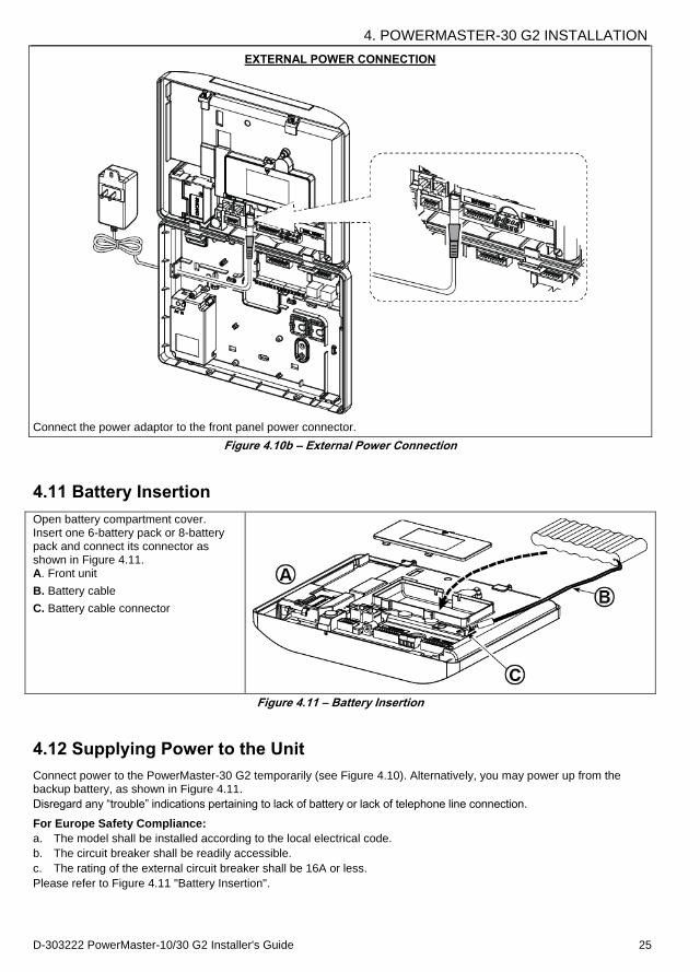
EXTERNAL POWER CONNECTION
Connect the power adaptor to the front panel power connector.
Figure 4.10b – External Power Connection
4.11 Battery Insertion
Open battery compartment cover. Insert one 6-battery pack or 8-battery pack and connect its connector as shown in Figure 4.11. A. Front unit
B. Battery cable
C. Battery cable connector
Figure 4.11 – Battery Insertion
4.12 Supplying Power to the Unit
Connect power to the PowerMaster-30 G2 temporarily (see Figure 4.10). Alternatively, you may power up from the backup battery, as shown in Figure 4.11.
Disregard any “trouble” indications pertaining to lack of battery or lack of telephone line connection.
For Europe Safety Compliance:
a. The model shall be installed according to the local electrical code.
b. The circuit breaker shall be readily accessible.
c. The rating of the external circuit breaker shall be 16A or less.
Please refer to Figure 4.11 "Battery Insertion".
4. POWERMASTER-30 G2 INSTALLATION
26 D-303222 PowerMaster-10/30 G2 Installer's Guide
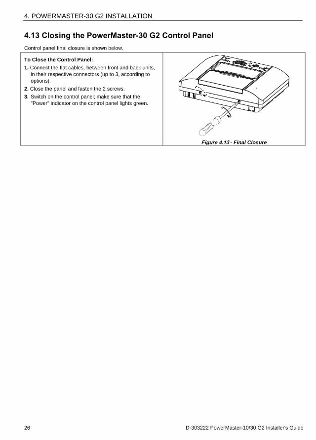
4.13 Closing the PowerMaster-30 G2 Control Panel
Control panel final closure is shown below.
To Close the Control Panel:
1. Connect the flat cables, between front and back units,
in their respective connectors (up to 3, according to
options).
2. Close the panel and fasten the 2 screws.
3. Switch on the control panel; make sure that the
"Power" indicator on the control panel lights green.
Figure 4.13 - Final Closure
5. PROGRAMMING
D-303222 PowerMaster-10/30 G2 Installer's Guide 27
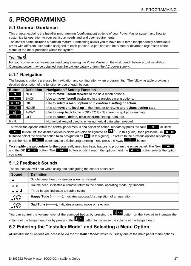
5. PROGRAMMING
5.1 General Guidance This chapter explains the Installer programming (configuration) options of your PowerMaster system and how to
customize its operation to your particular needs and end user requirements.
The control panel includes a partition feature. Partitioning allows you to have up to three independently controllable
areas with different user codes assigned to each partition. A partition can be armed or disarmed regardless of the
status of the other partitions within the system.
Tech Tip :
For your convenience, we recommend programming the PowerMaster on the work bench before actual installation.
Operating power may be obtained from the backup battery or from the AC power supply.
5.1.1 Navigation
The keypad's buttons are used for navigation and configuration when programming. The following table provides a
detailed description of the function or use of each button.
Button Definition Navigation / Setting Function NEXT Use to move / scroll forward to the next menu options.
BACK Use to move / scroll backward to the previous menu options.
OK Use to select a menu option or to confirm a setting or action.
HOME Use to move one level up in the menu or to return to previous setting step.
AWAY Use to jump back to the [<OK> TO EXIT] screen to quit programming.
OFF Use to cancel, delete, clear or erase setting, data, etc.
0 – 9 Numerical keypad used to enter numerical data when needed.
To review the options within the control panel menus and select an option, repeatedly press the Next or Back
button until the desired option is displayed (also designated as in this guide), then press the OK
button to select the desired option (also designated as in this guide). To return to the previous options repeatedly
press the Home button and to exit the programming menu press the Away button.
To simplify the procedure further, you really need two basic buttons to program the entire panel: The Next and the OK button. The button scrolls through the options, and the button selects the option
you want.
5.1.2 Feedback Sounds
The sounds you will hear while using and configuring the control panel are:
Sound Definition
Single beep, heard whenever a key is pressed
Double beep, indicates automatic return to the normal operating mode (by timeout).
Three beeps, indicates a trouble event
Happy Tune (- - - –––), indicates successful completion of an operation.
Sad Tune (–––––), indicates a wrong move or rejection
You can control the volume level of the sounded beeps by pressing the button on the keypad to increase the
volume of the beeps heard, or by pressing the button to decrease the volume of the beeps heard.
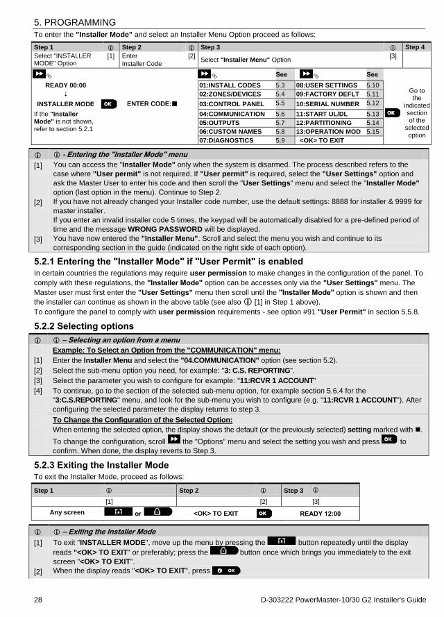
5.2 Entering the "Installer Mode" and Selecting a Menu Option
All installer menu options are accessed via the "Installer Mode" which is usually one of the main panel menu options.
5. PROGRAMMING
28 D-303222 PowerMaster-10/30 G2 Installer's Guide
To enter the "Installer Mode" and select an Installer Menu Option proceed as follows:
Step 1 Step 2 Step 3 Step 4
Select "INSTALLER MODE" Option
[1] Enter
Installer Code
[2] Select "Installer Menu" Option
[3]
See
See
READY 00:00 01:INSTALL CODES 5.3 08:USER SETTINGS 5.10
Go to the
indicated section of the
selected option
02:ZONES/DEVICES 5.4 09:FACTORY DEFLT 5.11
INSTALLER MODE ENTER CODE: 03:CONTROL PANEL 5.5 10:SERIAL NUMBER 5.12
If the "Installer Mode" is not shown, refer to section 5.2.1
04:COMMUNICATION 5.6 11:START UL/DL 5.13
05:OUTPUTS 5.7 12:PARTITIONING 5.14
06:CUSTOM NAMES 5.8 13:OPERATION MOD 5.15
07:DIAGNOSTICS 5.9 <OK> TO EXIT
- Entering the "Installer Mode" menu
[1] You can access the "Installer Mode" only when the system is disarmed. The process described refers to the
case where "User permit" is not required. If "User permit" is required, select the "User Settings" option and
ask the Master User to enter his code and then scroll the "User Settings" menu and select the "Installer Mode"
option (last option in the menu). Continue to Step 2.
[2] If you have not already changed your Installer code number, use the default settings: 8888 for installer & 9999 for
master installer.
If you enter an invalid installer code 5 times, the keypad will be automatically disabled for a pre-defined period of
time and the message WRONG PASSWORD will be displayed.
[3] You have now entered the "Installer Menu". Scroll and select the menu you wish and continue to its
corresponding section in the guide (indicated on the right side of each option).
5.2.1 Entering the "Installer Mode" if "User Permit" is enabled
In certain countries the regulations may require user permission to make changes in the configuration of the panel. To
comply with these regulations, the "Installer Mode" option can be accesses only via the "User Settings" menu. The
Master user must first enter the "User Settings" menu then scroll until the "Installer Mode" option is shown and then
the installer can continue as shown in the above table (see also [1] in Step 1 above).
To configure the panel to comply with user permission requirements - see option #91 "User Permit" in section 5.5.8.
5.2.2 Selecting options
– Selecting an option from a menu
Example: To Select an Option from the "COMMUNICATION" menu:
[1] Enter the Installer Menu and select the "04.COMMUNICATION" option (see section 5.2).
[2] Select the sub-menu option you need, for example: "3: C.S. REPORTING".
[3] Select the parameter you wish to configure for example: "11:RCVR 1 ACCOUNT"
[4] To continue, go to the section of the selected sub-menu option, for example section 5.6.4 for the
"3:C.S.REPORTING" menu, and look for the sub-menu you wish to configure (e.g. "11:RCVR 1 ACCOUNT"). After
configuring the selected parameter the display returns to step 3.
To Change the Configuration of the Selected Option:
When entering the selected option, the display shows the default (or the previously selected) setting marked with .
To change the configuration, scroll the "Options" menu and select the setting you wish and press to
confirm. When done, the display reverts to Step 3.
5.2.3 Exiting the Installer Mode
To exit the Installer Mode, proceed as follows:
Step 1 Step 2
Step 3
[1] [2] [3]
Any screen or <OK> TO EXIT READY 12:00
– Exiting the Installer Mode
[1] To exit "INSTALLER MODE", move up the menu by pressing the button repeatedly until the display
reads "<OK> TO EXIT" or preferably; press the button once which brings you immediately to the exit
screen "<OK> TO EXIT".
[2] When the display reads "<OK> TO EXIT", press .
5. PROGRAMMING
D-303222 PowerMaster-10/30 G2 Installer's Guide 29
[3] The system exits the “INSTALLER MODE" menu and returns to the normal disarm state while showing the
READY display.
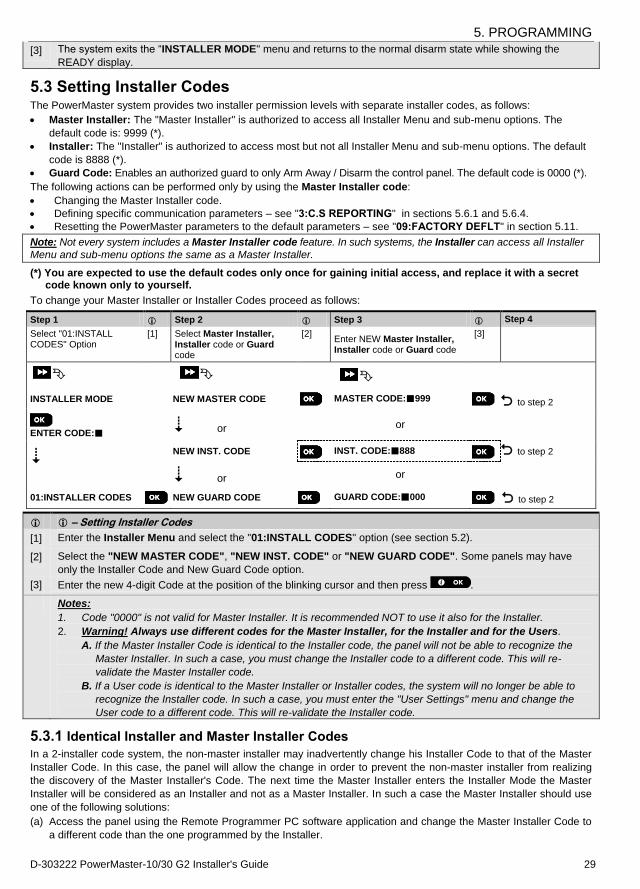
5.3 Setting Installer Codes The PowerMaster system provides two installer permission levels with separate installer codes, as follows:
Master Installer: The "Master Installer" is authorized to access all Installer Menu and sub-menu options. The
default code is: 9999 (*).
Installer: The "Installer" is authorized to access most but not all Installer Menu and sub-menu options. The default
code is 8888 (*).
Guard Code: Enables an authorized guard to only Arm Away / Disarm the control panel. The default code is 0000 (*).
The following actions can be performed only by using the Master Installer code:
Changing the Master Installer code.
Defining specific communication parameters – see "3:C.S REPORTING" in sections 5.6.1 and 5.6.4.
Resetting the PowerMaster parameters to the default parameters – see "09:FACTORY DEFLT" in section 5.11.
Note: Not every system includes a Master Installer code feature. In such systems, the Installer can access all Installer
Menu and sub-menu options the same as a Master Installer.
(*) You are expected to use the default codes only once for gaining initial access, and replace it with a secret code known only to yourself.
To change your Master Installer or Installer Codes proceed as follows:
Step 1 Step 2 Step 3 Step 4
Select "01:INSTALL CODES" Option
[1] Select Master Installer, Installer code or Guard code
[2] Enter NEW Master Installer, Installer code or Guard code
[3]
INSTALLER MODE NEW MASTER CODE MASTER CODE:999 to step 2
to step 2
ENTER CODE:
or
or
NEW INST. CODE INST. CODE:888
or or
01:INSTALLER CODES NEW GUARD CODE GUARD CODE:000 to step 2
– Setting Installer Codes
[1] Enter the Installer Menu and select the "01:INSTALL CODES" option (see section 5.2).
[2] Select the "NEW MASTER CODE", "NEW INST. CODE" or "NEW GUARD CODE". Some panels may have
only the Installer Code and New Guard Code option.
[3] Enter the new 4-digit Code at the position of the blinking cursor and then press .
Notes:
1. Code "0000" is not valid for Master Installer. It is recommended NOT to use it also for the Installer.
2. Warning! Always use different codes for the Master Installer, for the Installer and for the Users.
A. If the Master Installer Code is identical to the Installer code, the panel will not be able to recognize the
Master Installer. In such a case, you must change the Installer code to a different code. This will re-
validate the Master Installer code.
B. If a User code is identical to the Master Installer or Installer codes, the system will no longer be able to
recognize the Installer code. In such a case, you must enter the "User Settings" menu and change the
User code to a different code. This will re-validate the Installer code.
5.3.1 Identical Installer and Master Installer Codes In a 2-installer code system, the non-master installer may inadvertently change his Installer Code to that of the Master
Installer Code. In this case, the panel will allow the change in order to prevent the non-master installer from realizing
the discovery of the Master Installer's Code. The next time the Master Installer enters the Installer Mode the Master
Installer will be considered as an Installer and not as a Master Installer. In such a case the Master Installer should use
one of the following solutions:
(a) Access the panel using the Remote Programmer PC software application and change the Master Installer Code to
a different code than the one programmed by the Installer.
5. PROGRAMMING
30 D-303222 PowerMaster-10/30 G2 Installer's Guide
(b) i) Change the Installer Code to a temporary code, ii) exit the Installer Mode, iii) enter the Installer Mode again
using the Master Installer code (the Master Installer Code will now be accepted), iv) change the Master Installer
code to a different code, v) and change the NON-Master Installer Code back again (in other words, undo the
change to the temporary code) so that the NON-Master Installer can still enter the system.
It is also possible that a user inadvertently changes his User Code to the same code as that of the Installer Code or
Master Installer Code. In this case, the installer will not be able to enter the Installer Mode. The installer should perform
the same procedures as described above to solve this situation.
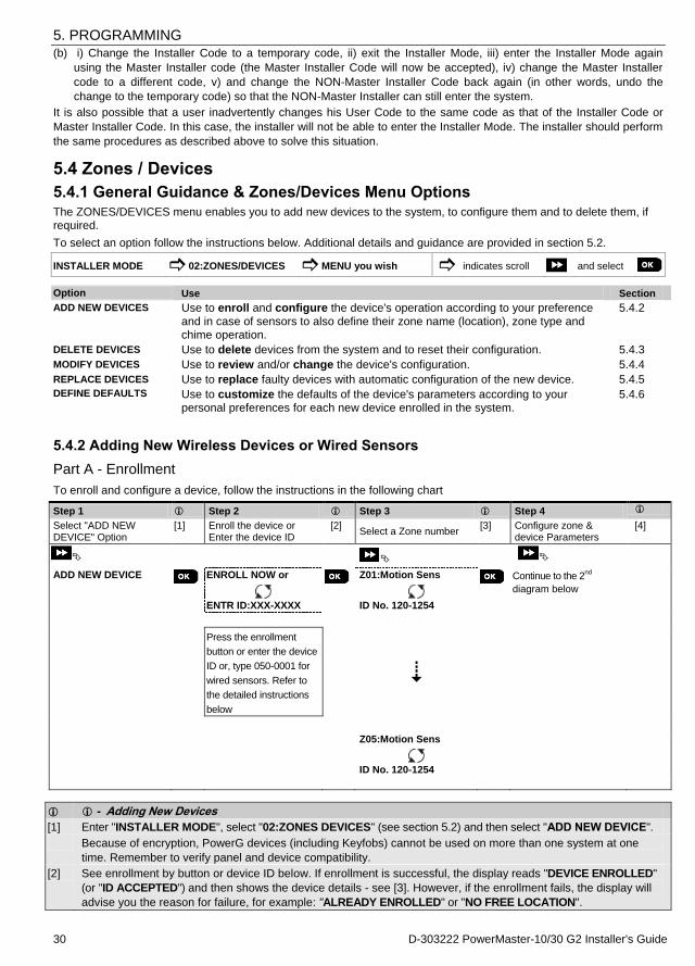
5.4 Zones / Devices
5.4.1 General Guidance & Zones/Devices Menu Options The ZONES/DEVICES menu enables you to add new devices to the system, to configure them and to delete them, if required.
To select an option follow the instructions below. Additional details and guidance are provided in section 5.2.
INSTALLER MODE 02:ZONES/DEVICES MENU you wish indicates scroll and select Option Use Section
ADD NEW DEVICES Use to enroll and configure the device's operation according to your preference
and in case of sensors to also define their zone name (location), zone type and chime operation.
5.4.2
DELETE DEVICES Use to delete devices from the system and to reset their configuration. 5.4.3
MODIFY DEVICES Use to review and/or change the device's configuration. 5.4.4
REPLACE DEVICES Use to replace faulty devices with automatic configuration of the new device. 5.4.5
DEFINE DEFAULTS Use to customize the defaults of the device's parameters according to your personal preferences for each new device enrolled in the system.
5.4.6
5.4.2 Adding New Wireless Devices or Wired Sensors
Part A - Enrollment
To enroll and configure a device, follow the instructions in the following chart
Step 1 Step 2
Step 3 Step 4
Select "ADD NEW DEVICE" Option
[1] Enroll the device or Enter the device ID
[2] Select a Zone number
[3] Configure zone & device Parameters
[4]
ADD NEW DEVICE
ENROLL NOW or
ENTR ID:XXX-XXXX
Z01:Motion Sens
ID No. 120-1254
Continue to the 2
nd
diagram below
Press the enrollment
button or enter the device
ID or, type 050-0001 for
wired sensors. Refer to
the detailed instructions
below
Z05:Motion Sens
ID No. 120-1254
- Adding New Devices
[1] Enter "INSTALLER MODE", select "02:ZONES DEVICES" (see section 5.2) and then select "ADD NEW DEVICE".
Because of encryption, PowerG devices (including Keyfobs) cannot be used on more than one system at one
time. Remember to verify panel and device compatibility.
[2] See enrollment by button or device ID below. If enrollment is successful, the display reads "DEVICE ENROLLED"
(or "ID ACCEPTED") and then shows the device details - see [3]. However, if the enrollment fails, the display will
advise you the reason for failure, for example: "ALREADY ENROLLED" or "NO FREE LOCATION".

5. PROGRAMMING
D-303222 PowerMaster-10/30 G2 Installer's Guide 31
[3] The display shows the device details and the first available free Zone number for example: "Z01:Motion
Sensor > ID No. 120-1254" (or "K01:Keyfob / S01:Siren etc. depending on the type of the enrolled device).
Both Wireless and wired detectors can be enrolled in any zone number. To change the zone number, click the
button or type in the zone number, and then press to confirm.
[4] Continue to Part B to configure the device – see diagram below
How to check Panel Device compatibility
Each PowerG device bears a 7-character Customer ID printed on the device sticker in the format: FFF-M:DDD, (for
example, 868-0:012) where FFF is the frequency band and M:DDD is the variant code. For PowerG system devices
compatibility, make sure the frequency (FFF) band of all devices are the same and that the variant code of the devices
match the variant code on the panel.
Enrollment by using Device ID
The 7-digit Device ID can be used to register a device into the panel locally or from a remote location using the Remote Programmer PC software. The enrollment by device ID is a 2 stage procedure.
In the 1st stage you register the devices' ID numbers into the panel and complete the device configuration. This can be
done from a remote location using the Remote Programmer PC software. Following the 1st stage, the PowerMaster
panel waits for the device to appear on the network in order to complete the enrollment.
In the 2nd
stage, the enrollment is completed when the panel is in full working mode by inserting the battery into the
device, or by pressing the tamper or enrollment button on the device. This procedure is very useful for adding devices
to existing systems without the need to provide technicians with the Installer Code, or to allow access to the
programming menus.
Remember! The system will indicate a "NOT NETWORKD" trouble until the 2nd
stage of all registered devices is completed.
Enrollment by using the Enrollment button
The panel is set to the Enrollment mode (step #2 above) and the device is enrolled using the Enroll button (refer to the
device information in the device Installation Instructions, then open the device and identify the Enroll button. For keyfobs and keypads, use the AUX '' button. For gas detectors, insert the battery.
Press the enroll button for 2-5 seconds until the LED turns ON and then release the button. The LED will extinguish or may blink for a few more seconds until the enrollment is completed. If enrollment is successfully completed, the PowerMaster sounds the "Happy Tune" and the LCD momentarily shows "DEVICE ENROLLED" and then reads the device details.
Enrollment of wired sensors
To enroll a wired sensor into the wired zone, enter ID: 050-0001 or 050-0002.
Part B - Configuration
Step 1 Step 2 Step 3 Step 4
Enter Location Menu [1] Select Location
(see list below) [2] Enter Zone Type [3] Select Zone Type
(see list below)
[4]
Z10:LOCATION
Front door
Kitchen
Z10:ZONE TYPE
1:Exit/Entry1
5. Interior
Step 5 Step 6 Step 7 Step 8
Enter Chime Menu [5] Select Chime option [6] Entr Partitions Menu [7] Select Partition options [8]
Z10:SET CHIME
Chime OFF
melody-chime
Z10:PARTITIONS
Z10:P1 P2 P3
Step 9 Step 10 Step 11
Enter Device Settings Menu
[9] Configure Device Parameters
[10] Continue or End
Z10:DEV SETTINGS Refer to device
datasheet in the device
Installation Instructions
for specific configuration
instructions.
To continue –
See [11]
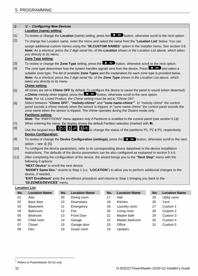
5. PROGRAMMING
32 D-303222 PowerMaster-10/30 G2 Installer's Guide
- Configuring New Devices
Location (name) setting:
[1] To review or change the Location (name) setting, press the button, otherwise scroll to the next option.
[2] To change the Location name, enter the menu and select the name from the "Location List" below. You can
assign additional custom names using the "06.CUSTOM NAMES" option in the Installer menu. See section 5.8.
Note: As a shortcut, press the 2 digit serial No. of the Location shown in the Location List above, which takes
you directly to its menu.
Zone Type setting:
[3] To review or change the Zone Type setting, press the button, otherwise scroll to the next option.
[4] The zone type determines how the system handles signals sent from the device. Press and select a
suitable zone type. The list of available Zone Types and the explanation for each zone type is provided below.
Note: As a shortcut, press the 2 digit serial No. of the Zone Type shown in the Location List above, which takes you directly to its menu.
Chime setting:
[5] All zones are set to Chime OFF by default. To configure the device to cause the panel to sound (when disarmed)
a Chime melody when tripped, press the button, otherwise scroll to the next option.
Note: For UL Listed Product, the Chime setting must be set to “Chime ON”.
[6] Select between "Chime OFF", "melody-chime" and "zone name-chime"1. In "melody chime" the control
panel sounds a chime melody when the sensor is tripped. In "zone name-chime" the control panel sounds the zone name when the sensor is tripped. The chime operates during the Disarm mode only.
Partitions setting:
Note: The "PARTITIONS" menu appears only if Partitions is enabled in the control panel (see section 5.14).
[7] When entering the menu, the display shows the default Partition selection (marked with ).
[8] Use the keypad keys , , to change the status of the partitions P1, P2 & P3, respectively.
Device Configuration:
[9] To review or change the Device Configuration (settings), press the button, otherwise scroll to the next
option – see [5].
[10] To configure the device parameters, refer to its corresponding device datasheet in the device Installation
Instructions. The defaults of the device parameters can be also configured as explained in section 5.4.6.
[11] After completing the configuration of the device, the wizard brings you to the "Next Step" menu with the
following 3 options:
"NEXT Device" to enroll the next device.
"MODIFY Same Dev." reverts to Step 1 (i.e. "LOCATION") to allow you to perform additional changes to the
device, if needed.
"EXIT Enrollment" exits the enrollment procedure and returns to Step 1 bringing you back to the
"02:ZONES/DEVICES" menu.
Location List
No. Location Name No. Location Name No. Location Name No. Location Name
01 Attic 09 Dining room 17 Hall 25 Utility room
02 Back door 10 Downstairs 18 Kitchen 26 Yard
03 Basement 11 Emergency 19 Laundry room 27 Custom 1
04 Bathroom 12 Fire 20 Living room 28 Custom 2
05 Bedroom 13 Front Door 21 Master bath 29 Custom 3
06 Child room 14 Garage 22 Master bedroom 30 Custom 4
07 Closet 15 Garage door 23 Office 31 Custom 5
08 Den 16 Guest room 24 Upstairs
1 Refers to PowerMaster-30 G2 only
5. PROGRAMMING
D-303222 PowerMaster-10/30 G2 Installer's Guide 33
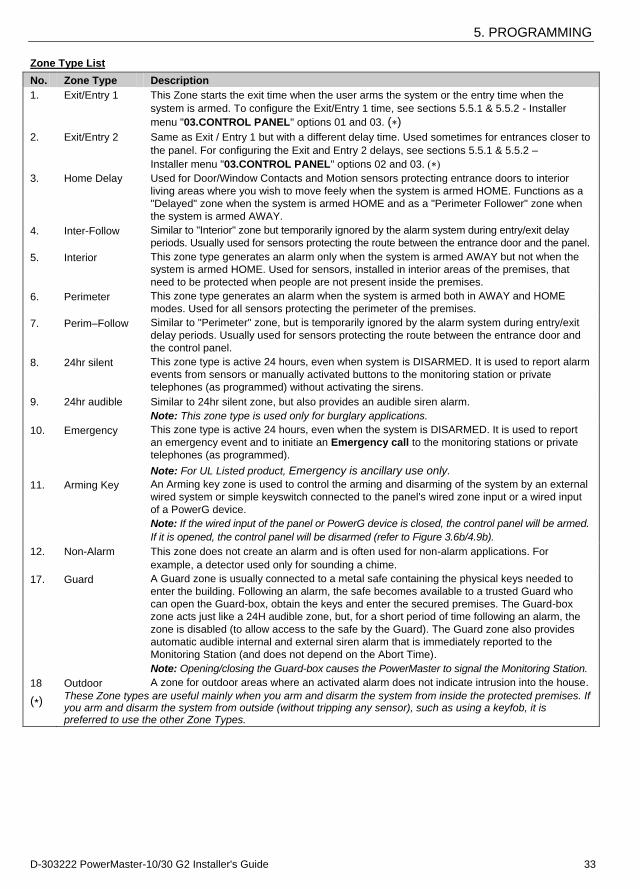
Zone Type List
No. Zone Type Description
1. Exit/Entry 1 This Zone starts the exit time when the user arms the system or the entry time when the
system is armed. To configure the Exit/Entry 1 time, see sections 5.5.1 & 5.5.2 - Installer
menu "03.CONTROL PANEL" options 01 and 03. (∗) 2. Exit/Entry 2 Same as Exit / Entry 1 but with a different delay time. Used sometimes for entrances closer to
the panel. For configuring the Exit and Entry 2 delays, see sections 5.5.1 & 5.5.2 –
Installer menu "03.CONTROL PANEL" options 02 and 03. (∗)
3. Home Delay Used for Door/Window Contacts and Motion sensors protecting entrance doors to interior
living areas where you wish to move feely when the system is armed HOME. Functions as a
"Delayed" zone when the system is armed HOME and as a "Perimeter Follower" zone when
the system is armed AWAY.
4. Inter-Follow Similar to "Interior" zone but temporarily ignored by the alarm system during entry/exit delay
periods. Usually used for sensors protecting the route between the entrance door and the panel.
5. Interior This zone type generates an alarm only when the system is armed AWAY but not when the
system is armed HOME. Used for sensors, installed in interior areas of the premises, that
need to be protected when people are not present inside the premises.
6. Perimeter This zone type generates an alarm when the system is armed both in AWAY and HOME
modes. Used for all sensors protecting the perimeter of the premises.
7. Perim–Follow Similar to "Perimeter" zone, but is temporarily ignored by the alarm system during entry/exit
delay periods. Usually used for sensors protecting the route between the entrance door and
the control panel.
8. 24hr silent This zone type is active 24 hours, even when system is DISARMED. It is used to report alarm
events from sensors or manually activated buttons to the monitoring station or private
telephones (as programmed) without activating the sirens.
9. 24hr audible Similar to 24hr silent zone, but also provides an audible siren alarm.
Note: This zone type is used only for burglary applications.
10. Emergency This zone type is active 24 hours, even when the system is DISARMED. It is used to report
an emergency event and to initiate an Emergency call to the monitoring stations or private
telephones (as programmed).
Note: For UL Listed product, Emergency is ancillary use only.
11. Arming Key An Arming key zone is used to control the arming and disarming of the system by an external
wired system or simple keyswitch connected to the panel's wired zone input or a wired input
of a PowerG device.
Note: If the wired input of the panel or PowerG device is closed, the control panel will be armed.
If it is opened, the control panel will be disarmed (refer to Figure 3.6b/4.9b).
12. Non-Alarm This zone does not create an alarm and is often used for non-alarm applications. For
example, a detector used only for sounding a chime.
17. Guard A Guard zone is usually connected to a metal safe containing the physical keys needed to
enter the building. Following an alarm, the safe becomes available to a trusted Guard who
can open the Guard-box, obtain the keys and enter the secured premises. The Guard-box
zone acts just like a 24H audible zone, but, for a short period of time following an alarm, the
zone is disabled (to allow access to the safe by the Guard). The Guard zone also provides
automatic audible internal and external siren alarm that is immediately reported to the
Monitoring Station (and does not depend on the Abort Time).
Note: Opening/closing the Guard-box causes the PowerMaster to signal the Monitoring Station.
18 Outdoor A zone for outdoor areas where an activated alarm does not indicate intrusion into the house.
(∗) These Zone types are useful mainly when you arm and disarm the system from inside the protected premises. If you arm and disarm the system from outside (without tripping any sensor), such as using a keyfob, it is preferred to use the other Zone Types.

5. PROGRAMMING
34 D-303222 PowerMaster-10/30 G2 Installer's Guide
5.4.3 Deleting a Device
Step 1 Step 2 Step 3 Step 4 Step 5
Select "DELETE DEVICES" Option
[1] Select the respective device Group
[2] Select exact device you wish to delete
[3] To delete the device:
press the key
[4]
02:ZONES DEVICES CONTACT SENSORS
DELETE DEVICES MOTION SENSORS
Z01:Motion Sens
ID No. 120-1254
<OFF> TO DELETE
to step 2
– Deleting a Device [1] Enter the Installer Menu, select the "02.ZONES/DEVICES" option (see section 5.2) and then select the
"DELETE DEVICES" option.
[2] Select the respective group of the device you wish to delete. For example, "MOTION SENSORS". [3] Scroll the Device Group, identify (by zone and/or ID number) the exact device you wish to replace, for example:
"Z01: Motion Sensor > ID No. 120-1254" and press the button.
[4] The display prompts you "<OFF> TO DELETE". To delete the device, press the (OFF) button.
5.4.4 Modifying or Reviewing a Device
To Modify or Review the device parameters proceed as follows:
Step 1 Step 2 Step 3 Step 4 Step 5
Select "MODIFY DEVICES" Option
[1] Select the respective device Group
[2] Select exact device
you wish to modify
[3] Select the Parameter you wish to modify
[4] Modify the Parameter
02:ZONES DEVICES CONTACT SENSORS
MODIFY SENSORS MOTION SENSORS
Z10:Motion Camra
ID No. 140-1737
Z10:LOCATION
Z10:ZONE TYPE
Z10:SET CHIME
Z10:PARTITIONS
Z10:DEV SETTINGS
See [4] When done to step 2
– Modifying or Reviewing a Device
[1] Enter the Installer Menu, select the "02:ZONES/DEVICES" option (see section 5.2) and then select the "MODIFY
DEVICES" option.
[2] Select the respective group of the device you wish to review or modify. For example, "MOTION SENSORS".
[3] Scroll the Device Group, identify (by zone and/or ID number) of the exact device you wish to modify or review, for
example: "Z10:Motion Camra > ID No. 140-1737".
[4] From here on the process is same as the configuration process that follows the enrollment of that device. To
continue, refer to Section 5.4.2 "Adding a New Wireless Device" Part B. When done, the display will show the
next device of the same type (i.e. "Motion camera").
5.4.5 Replacing a Device Use this option to replace a faulty device that is enrolled in the system with another device of the same type number (i.e. same first 3 digit of the ID number – see section 5.4.2.A) while keeping the same configuration of the original device. There is no need to delete the faulty device or to reconfigure the new device. Once enrolled, the new device will be configured automatically to the same configuration of the faulty (replaced) device.
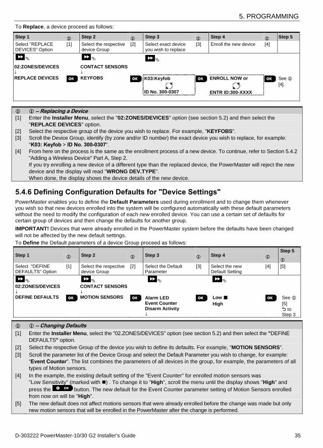
5. PROGRAMMING
D-303222 PowerMaster-10/30 G2 Installer's Guide 35
To Replace, a device proceed as follows:
Step 1 Step 2 Step 3 Step 4 Step 5
Select "REPLACE DEVICES" Option
[1] Select the respective device Group
[2] Select exact device you wish to replace
[3] Enroll the new device [4]
02:ZONES/DEVICES CONTACT SENSORS
REPLACE DEVICES KEYFOBS
K03:Keyfob
ID No. 300-0307
ENROLL NOW or
ENTR ID:300-XXXX
See
[4].
– Replacing a Device [1] Enter the Installer Menu, select the "02:ZONES/DEVICES" option (see section 5.2) and then select the
"REPLACE DEVICES" option.
[2] Select the respective group of the device you wish to replace. For example, "KEYFOBS". [3] Scroll the Device Group, identify (by zone and/or ID number) the exact device you wish to replace, for example:
"K03: Keyfob > ID No. 300-0307".
[4] From here on the process is the same as the enrollment process of a new device. To continue, refer to Section 5.4.2
"Adding a Wireless Device" Part A, Step 2.
If you try enrolling a new device of a different type than the replaced device, the PowerMaster will reject the new
device and the display will read "WRONG DEV.TYPE".
When done, the display shows the device details of the new device.
5.4.6 Defining Configuration Defaults for "Device Settings"
PowerMaster enables you to define the Default Parameters used during enrollment and to change them whenever you wish so that new devices enrolled into the system will be configured automatically with these default parameters without the need to modify the configuration of each new enrolled device. You can use a certain set of defaults for certain group of devices and then change the defaults for another group.
IMPORTANT! Devices that were already enrolled in the PowerMaster system before the defaults have been changed
will not be affected by the new default settings.
To Define the Default parameters of a device Group proceed as follows:
Step 1 Step 2 Step 3 Step 4 Step 5
Select "DEFINE DEFAULTS" Option
[1] Select the respective device Group
[2] Select the Default Parameter
[3] Select the new Default Setting
[4] [5]
02:ZONES/DEVICES CONTACT SENSORS DEFINE DEFAULTS
MOTION SENSORS
Alarm LED Event Counter Disarm Activity
Low
High
See
[5]
to Step 3
– Changing Defaults
[1] Enter the Installer Menu, select the "02.ZONES/DEVICES" option (see section 5.2) and then select the "DEFINE
DEFAULTS" option.
[2] Select the respective Group of the device you wish to define its defaults. For example, "MOTION SENSORS".
[3] Scroll the parameter list of the Device Group and select the Default Parameter you wish to change, for example:
"Event Counter". The list combines the parameters of all devices in the group, for example, the parameters of all
types of Motion sensors.
[4] In the example, the existing default setting of the "Event Counter" for enrolled motion sensors was
"Low Sensitivity" (marked with ) . To change it to "High", scroll the menu until the display shows "High" and
press the button. The new default for the Event Counter parameter setting of Motion Sensors enrolled
from now on will be "High".
[5] The new default does not affect motions sensors that were already enrolled before the change was made but only
new motion sensors that will be enrolled in the PowerMaster after the change is performed.
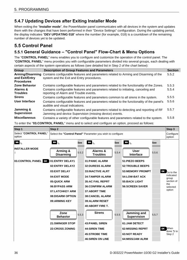
5. PROGRAMMING
36 D-303222 PowerMaster-10/30 G2 Installer's Guide
5.4.7 Updating Devices after Exiting Installer Mode
When exiting the "Installer mode", the PowerMaster panel communicates with all devices in the system and updates
them with the changes that have been performed in their "Device Settings" configuration. During the updating period,
the display indicates "DEV UPDATING 018" where the number (for example, 018) is a countdown of the remaining
number of devices yet to be updated.
5.5 Control Panel
5.5.1 General Guidance – "Control Panel" Flow-Chart & Menu Options
The "CONTROL PANEL" menu enables you to configure and customize the operation of the control panel. The
"CONTROL PANEL" menu provides you with configurable parameters divided into several groups, each dealing with
certain aspects of the system operations as follows (see detailed list in Step 2 of the chart below):
Group Description of Group Features and Parameters Section
Arming/Disarming and Exit/Entry Procedures
Contains configurable features and parameters related to Arming and Disarming of the
system and the Exit and Entry procedures.
5.5.2
Zone Behavior Contains configurable features and parameters related to the functionality of the Zones. 5.5.3
Alarms & Troubles
Contains configurable features and parameters related to initiating, canceling and reporting of Alarm and Trouble events.
5.5.4
Sirens Contains configurable features and parameters common to all sirens in the system. 5.5.5
User Interface Contains configurable features and parameters related to the functionality of the panel's
audible and visual indications.
5.5.6
Jamming & Supervision
Contains configurable features and parameters related to detecting and reporting of RF
Jamming and device Supervision (missing device) events.
5.5.7
Miscellaneous Contains a variety of other configurable features and parameters related to the system. 5.5.8
To enter the "03.CONTROL PANEL" menu and to select and configure an option, proceed as follows:
Step 1 Step 2 Step 3
Select "CONTROL PANEL" option
Select the "Control Panel" Parameter you wish to configure Configure option
See See See
INSTALLER MODE
5.5.2
5.5.4
5.5.6
03.CONTROL PANEL
01:ENTRY DELAY1 31:PANIC ALARM 51:PIEZO BEEPS
Go to the indicated group section of the selected option
02:ENTRY DELAY2 32:DURESS ALARM 52:TROUBLE BEEPS
03:EXIT DELAY 33:INACTIVE ALRT 53:MEMORY PROMPT
04:EXIT MODE 34:TAMPER ALARM 54:LOW-BAT ACK
05:QUICK ARM 35:AC FAIL REPRT 55:BACK LIGHT
06:BYPASS ARM 36:CONFIRM ALARM 56:SCREEN SAVER
07:LATCHKEY ARM 37:ABORT TIME
08:DISARM OPTION 38:CANCEL ALARM
09:ARMING KEY 39:ALARM RESET
40:ABORT FIRE T.
5.5.3
5.5.5
5.5.7
21:SWINGER STOP 43:PANEL SIREN 61:JAM DETECT
When done to Step 2
22:CROSS ZONING 44:SIREN TIME 62:MISSING REPRT
45:STROBE TIME 63:NOT READY
46:SIREN ON LINE 64:MISS/JAM ALRM
Sirens Jamming and Supervision
Zone Behavior
User Interface
Arming & Disarming
Alarms & Troubles
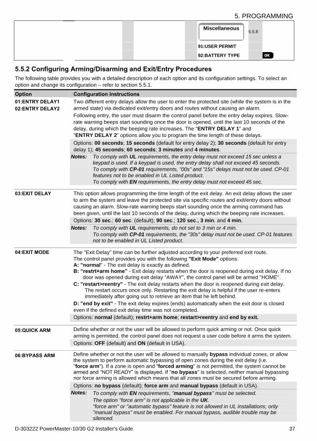
5. PROGRAMMING
D-303222 PowerMaster-10/30 G2 Installer's Guide 37
5.5.8
91:USER PERMIT
92:BATTERY TYPE
5.5.2 Configuring Arming/Disarming and Exit/Entry Procedures
The following table provides you with a detailed description of each option and its configuration settings. To select an
option and change its configuration – refer to section 5.5.1.
Option Configuration Instructions
01:ENTRY DELAY1
02:ENTRY DELAY2
Two different entry delays allow the user to enter the protected site (while the system is in the
armed state) via dedicated exit/entry doors and routes without causing an alarm.
Following entry, the user must disarm the control panel before the entry delay expires. Slow-
rate warning beeps start sounding once the door is opened, until the last 10 seconds of the
delay, during which the beeping rate increases. The "ENTRY DELAY 1" and
"ENTRY DELAY 2" options allow you to program the time length of these delays.
Options: 00 seconds; 15 seconds (default for entry delay 2); 30 seconds (default for entry
delay 1); 45 seconds; 60 seconds; 3 minutes and 4 minutes.
Notes:
To comply with UL requirements, the entry delay must not exceed 15 sec unless a keypad is used. If a keypad is used, the entry delay shall not exceed 45 seconds.
To comply with CP-01 requirements, "00s" and "15s" delays must not be used. CP-01 features not to be enabled in UL Listed product.
To comply with EN requirements, the entry delay must not exceed 45 sec.
03:EXIT DELAY This option allows programming the time length of the exit delay. An exit delay allows the user
to arm the system and leave the protected site via specific routes and exit/entry doors without
causing an alarm. Slow-rate warning beeps start sounding once the arming command has
been given, until the last 10 seconds of the delay, during which the beeping rate increases.
Options: 30 sec.; 60 sec. (default); 90 sec.; 120 sec., 3 min. and 4 min.
Notes:
To comply with UL requirements, do not set to 3 min or 4 min.
To comply with CP-01 requirements, the "30s" delay must not be used. CP-01 features not to be enabled in UL Listed product.
04:EXIT MODE The "Exit Delay" time can be further adjusted according to your preferred exit route.
The control panel provides you with the following "Exit Mode" options: A: "normal" - The exit delay is exactly as defined. B: “restrt+arm home” - Exit delay restarts when the door is reopened during exit delay. If no
door was opened during exit delay "AWAY", the control panel will be armed "HOME".
C: "restart>reentry" - The exit delay restarts when the door is reopened during exit delay. The restart occurs once only. Restarting the exit delay is helpful if the user re-enters immediately after going out to retrieve an item that he left behind.
D: "end by exit" - The exit delay expires (ends) automatically when the exit door is closed
even if the defined exit delay time was not completed.
Options: normal (default); restrt+arm home; restart>reentry and end by exit.
05:QUICK ARM Define whether or not the user will be allowed to perform quick arming or not. Once quick
arming is permitted, the control panel does not request a user code before it arms the system.
Options: OFF (default) and ON (default in USA).
06:BYPASS ARM Define whether or not the user will be allowed to manually bypass individual zones, or allow the system to perform automatic bypassing of open zones during the exit delay (i.e. "force arm"). If a zone is open and "forced arming" is not permitted, the system cannot be armed and “NOT READY” is displayed. If "no bypass" is selected, neither manual bypassing nor force arming is allowed which means that all zones must be secured before arming.
Options: no bypass (default); force arm and manual bypass (default in USA).
Notes:
To comply with EN requirements, "manual bypass" must be selected.
The option "force arm" is not applicable in the UK. "force arm" or "automatic bypass" feature is not allowed in UL installations; only "manual bypass" must be enabled. For manual bypass, audible trouble may be silenced.
Miscellaneous
5. PROGRAMMING
38 D-303222 PowerMaster-10/30 G2 Installer's Guide
Option Configuration Instructions
07:LATCHKEY ARM When "ON", a “latchkey” message will be reported by voice1 or SMS message to users (see
Note) upon disarming by a “latchkey user” (users 5-8 or keyfob transmitters 5-8 in PowerMaster-
10 G2 system / users 23-32 or keyfob transmitters 23-32 in PowerMaster-30 G2 system). This
mode is useful when parents at work want to be informed of a child’s return from school.
Options: OFF (default) and ON.
Notes:
To enable the reporting, you must configure the system to report "alrt" events to Private users
(Latchkey belongs to the "alerts" group of events). Refer to section 5.6.4 "REPORTED
EVENTS" option in both "VOICE REPORT" & "SMS REPORT" menus.
Latchkey Arming is supplemental in UL installations.
08:DISARM OPTION Certain regulations require that when the system is armed in AWAY mode, it may not be
disarmed from the outside of the house (such as by keyfobs) before entering the protected
premises and activating an "Entry Delay" zone. To answer this requirement, the PowerMaster
provides you with the following configurable options to disarm the system:
A: At "any time" (default), the system can be disarmed at all times from all devices.
B: During entry delay, the system can be disarmed only using keyfob or prox operated devices ("on entry wrless").
C: During entry delay by code, the system can be disarmed only using PowerMaster panel keypad ("entry + away kp.").
D: During entry delay, the system can be disarmed using keyfobs or by code using the PowerMaster panel keypad ("on entry all.").
09:ARMING KEY Determine that, when activated, the Arming Key will arm AWAY or HOME.
Options: arm AWAY (default) and arm HOME.
Note: Arming Key not to be enabled in UL Listed product.
5.5.3 Configuring Zones Functionality
The following table provides you with a detailed description of each option and its configuration settings. To select an
option and change its configuration – refer to section 5.5.1.
Option Configuration Instructions
21:SWINGER STOP Define the number of times a zone is allowed to initiate an alarm within a single arming/disarming period (including tamper & power failure events of detectors, etc.). If the number of alarms from a specific zone exceeds the programmed number, the control panel automatically bypasses the zone to prevent recurrent siren noise and excessive reporting to the Monitoring Station. The zone will be reactivated upon disarming, or 48 hours after having been bypassed (if the system remains armed).
Options: after 1 alarm (default); after 2 alarms (default in USA); after 3 alarms and no stop.
Notes: 1. CP-01 was tested and certified by ETL/Intertek.
2. CP-01 features not to be enabled in UL Listed product.
22:CROSS ZONING Define whether cross zoning will be active "ON" or inactive "OFF" (default). Cross zoning is a
method used to counteract false alarms - an alarm will be initiated only when two adjacent
zones (zone couples) are violated within a 30-second time window.
This feature is active only when the system is armed AWAY and only with respect to the
following zone couples: 18+19, 20+21, 22+23, 24+25, 26+27 in PowerMaster-10 G2 system / 40+41, 42+43, 44+45, 46+47, 48+49, 50+51, 52+53, 54+55, 56+57, 58+59, 60+61, 62+63 in PowerMaster-30 G2 system.
Notes:
1. If one of the two crossed zones is bypassed (see Section 5.5.2), the remaining
zone will function independently.
2. It is recommended that crossed zones will be only zones used for detection of
burglary i.e. "Zone Types": Entry/ Exit, Interior, Perimeter and Perimeter follower.
1 Refers to PowerMaster-30 G2 with voice option only
5. PROGRAMMING
D-303222 PowerMaster-10/30 G2 Installer's Guide 39
Option Configuration Instructions
3. CP-01 was tested and certified by ETL/Intertek.
4. CP-01 features not to be enabled in UL Listed product.
Important! Do not define "cross zoning" to any other zone types such as Fire,
Emergency, 24h audible, 24h silent etc.
5.5.4 Configuring Alarms & Troubles
The following table provides you with a detailed description of each option and its configuration settings. To select an
option and change its configuration – refer to section 5.5.1.
Option Configuration Instructions
31:PANIC ALARM Define whether or not the user will be allowed to initiate a Panic Alarm from keypads (by
simultaneous pressing the two "Panic Buttons") or keyfobs (by simultaneous pressing the
"Away" + "Home" buttons) and whether the alarm will be "silent" (i.e. only reporting of the
event) or also audible (i.e. the sirens will also sound).
Options: audible (default); silent and disabled.
32:DURESS ALARM
(not applicable in UK)
A duress (ambush) alarm message can be sent to the Monitoring Station if the user is forced
to disarm the system under violence or menace. To initiate a duress message, the user must disarm the system using a duress code (2580 by default).
To change the code, enter the new 4-digit of the new Duress code at the position of the
blinking cursor or enter 0000 to disable the duress function and then press .
Notes: The system does not allow programming a duress code identical to an existing user code.
33:INACTIVE ALRT
Previously known as "NOT ACTIVE"
If no sensor detects movement in interior zones at least once within the defined time window,
an “inactive alert" event is initiated.
Define the time window for monitoring the lack of motion.
Options: disabled (default); after: 3/6/12/24/48/72 hours
34:TAMPER ALARM Define whether the Tamper switch protection of all zones and other peripheral devices
(except the control panel) are "active" (default) or "not active".
Warning!: If you select "not active", be aware that no alarm or report will be initiated in case
of tampering with any of the system peripheral devices.
Note: Tamper alarm must be active in UL Listed product.
35:AC FAIL RPRT To avoid nuisance reporting in case of short interruptions in the house of AC power, the
system reports an AC Fail message only if the AC power does not resume within a pre-
determined time delay.
Options: after 5 minute (default), after 30 minute, after 60 minute or after 3 hours.
Notes:
To comply with EN requirements, the time delay must not exceed 60 min.
Not tested by UL, tested by Intertek.
36:CONFIRM ALARM
Previously known as "CONFIRM TIME"
If two successive alarm events occur within a specific time window, the system can be configured to report the second alarm event as a "confirmed alarm" (see section 5.6.4
option 61). You can activate this feature and set the respective time window.
Options: disable (default in USA); in 30/45/60 (default)/90 minutes
Notes:
1. CP-01 was tested and certified by ETL/Intertek.
2. CP-01 features not to be enabled in UL Listed product.
37:ABORT TIME The PowerMaster can be configured to provide a delay before reporting an alarm to the
monitoring station (not applicable to alarms from FIRE, 24H SILENT and EMERGENCY
zones). During this delay period, the siren sounds but the alarm is not reported. If the user
5. PROGRAMMING
40 D-303222 PowerMaster-10/30 G2 Installer's Guide
Option Configuration Instructions
disarms the system within the delay time, the alarm is aborted. You can activate the feature
and select the "Abort Time" interval.
Options: in 00 (default in USA)/15/30 (default)/45/60 seconds; in 2/3/4 minutes
Note:
To comply with UL or CP-01 requirements, the abort time must not exceed 45 sec. CP-01 features not to be enabled in UL Listed product.
38:CANCEL ALARM
Previously known as "ALARM CANCEL"
The PowerMaster can be configured to provide a ”Cancel Alarm” time window that starts upon reporting an alarm to the Monitoring Station. If the user disarms the system within that "cancel alarm" time, a “cancel alarm” message is sent to the Monitoring Station indicating that the alarm was canceled by the user.
Options: not active (default in USA); in 1/5 (default)/15/60 minute(s) and in 4 hours.
Notes:
1. To comply with CP-01 requirements, "1 minute" option must not be used. CP-01 features not to be enabled in UL Listed product.
.
39:ALARM RESET
Previously known as "RESET OPTIONS"
The PowerMaster provides you with the following configurable options for resetting the alarm
condition and rearming the system:
By the user as usual - by user (default). By the engineer (installer) by entering and exiting the "Installer Mode" or by accessing the system remotely via the telephone using the Installer Code (by engineer). For accessing the system via the telephone, see the User's Guide, Chapter 7 – "Remote Control by Telephone" and use the installer code instead of the user code.
Notes:
1. This feature is not applicable in the USA.
2. This feature is not to be not to be enabled in UL Listed product.
40:ABORT FIRE T.
The PowerMaster is able to provide an “abort interval” that starts upon detection of a Fire event.
During this interval, the buzzer sounds a warning but the siren remains inactive and the alarm is not reported. If the user disarms the system within the allowed abort interval, the alarm is aborted.
The menu allows configuration of the length of time allowed by the system to abort a Fire alarm.
Options: 00 (default)/30/60/90 seconds
5.5.5 Configuring Sirens Functionality
The following table provides you with a detailed description of each option and its configuration settings. To select an
option and change its configuration – refer to section 5.5.1.
Option Configuration Instructions
43:PANEL SIREN
Previously known as "PIEZO SIREN"
Determine whether the control panel's built-in siren will sound alarms – "ON" (default) or
remain silent – "OFF".
Notes:
1. Panel siren must be enabled unless an external sounder is connected to the product.
2. For UL installations, when set to “OFF” the SR-720 PG2 and SR-730 PG2 sirens must be
connected.
44:SIREN TIME
Previously known as "BELL TIME"
Define the period of time the sirens will sound upon alarm.
Options: 1/3/4 (default)/8/10/15/20 minute(s).
Notes:
1. To comply with EN requirements, the "Siren Time" must not exceed 15 minutes.
2. For Canada, the "Siren Time" must be set to 8 minutes
3. In UL installations, set siren time to 4 minutes min.
5. PROGRAMMING
D-303222 PowerMaster-10/30 G2 Installer's Guide 41
45:STROBE TIME Define the length of time the strobe light will flash upon alarm.
Options: 5/10/20 (default)/40/60 minutes.
46:SIREN ON LINE
Determine if the siren will be activated when the phone line fails and the system is armed.
Options: disable on fail (default) or enable on fail.
5.5.6 Configuring Audible & Visual User Interface
The following table provides you with a detailed description of each option and its configuration settings. To select an
option and change its configuration – refer to section 5.5.1.
Option Configuration Instructions
51:PIEZO BEEPS
With Partition disabled
Define whether the panel will sound the exit/entry warning beeps during exit and entry delays or
not. An additional option is to mute the warning beeps only when the system is armed “HOME”.
Options: ON (default), OFF when home (default in USA) and OFF, and OFF exit home.
Note: When exit beeps are OFF, the happy (success) melody will still sound toward the end of
an exit delay.
The volume level of the exit / entry beeps can be modified by pressing the button on
the keypad to increase the volume, or by pressing the button to decrease the volume.
51:PIEZO BEEPS
With Partition enabled
Define whether the panel will sound the exit/entry warning beeps during exit and entry delays or
not. An additional option is to mute the warning beeps only when the system is armed “HOME”.
The control panel’s display is: Def:P1 P2 P3
The pushbuttons , , and provide selection of the corresponding partitions.
Pressing each button repeatedly will toggle between each option.
Options: (enable beeps), H (OFF when home) h (OFF exit home) and (disable beeps).
Notes:
When exit beeps are OFF, the happy (success) melody will still sound toward the end of an
exit delay.
The volume level of the exit / entry beeps can be modified by pressing the button on
the keypad to increase the volume, or by pressing the button to decrease the volume.
52:TROUBLE BEEPS Under trouble conditions, the panel sounder emits a series of 3 short reminder beeps once per
minute. Define whether to enable or disable this reminder beeping or just disable it at night.
The “night” hours are defined in the factory but are usually from 8 PM (20:00) until 7:00 AM.
Options: ON (default in USA); OFF at night (default) and OFF.
Note: Audible trouble beeps to be enabled for UL Listed product.
53:MEMORY PROMPT Define whether or not the user will receive "Memory" LCD indication that an alarm has been
activated. By pressing the button in standby mode, you can view details of the alarm
memory.
Options: ON (default) and OFF.
Note: For UL installations, set to “ON”.
54:LOW-BAT ACK You can activate or deactivate the "Low Battery Acknowledge" requirement from the user whose
keyfob's battery is low. For further information, see PowerMaster User's Guide Chapter 5.
Options: OFF (default) – acknowledge not needed; ON – acknowledge required.
Note: For UL installations, Low Battery Acknowledge must be set to ”ON".
55:BACK LIGHT Define whether the panel's back lighting will remain on at all times or will turn on only when a
key is pressed and turn off within 10 seconds if no further keystrokes are sensed.
Options: always ON and OFF after 10 sec (default).
5. PROGRAMMING
42 D-303222 PowerMaster-10/30 G2 Installer's Guide
Option Configuration Instructions
56:SCREEN SAVER
With Partition disabled
The Screen Saver option (when activated) replaces the status display with “POWERMASTER-10” / “POWERMASTER-30” display if no key is pressed during more than 30 seconds.
You can activate the Screen Saver and determine whether the status display will resume
following any key press (refresh by Key) or by entering a code (refresh by Code). If refresh
by Key is selected, the first pressing of any key (except Fire and Emergency) will produce the
status display and the second press will perform the key function. For further information, see
the User's Guide, Chapter 1, "Screen Saver Mode".
Options: OFF (default); refresh by code and refresh by key.
Notes:
1. To comply with EN requirements, "refresh by code" must be selected.
2. For Fire and Emergency keys, the first key press will produce the status display and will also perform the Fire/Emergency function.
56:SCREEN SAVER
With Partition enabled
Certain regulations require that the system status display will not be exposed to unauthorized persons. The Screen Saver option (when activated) replaces the system status indication on the LCD with idle text if no key is pressed during more than 30 seconds.
You can activate the Screen Saver option and determine whether the status display will
resume following any key press (Text - by Key) or by entering a code (Text - by Code). If
Text by Key is selected, the first pressing of any key (except Fire and Emergency) will
produce the status display and the second press will perform the key function. Regarding the
Fire and Emergency keys, the first key press will produce the status display and will also
perform the Fire/Emergency function.
You can also determine that if no key is pressed during more than 30 seconds the date and time will appear on the display. You can determine that normal display will return after
pressing the button followed by entering user code (Clock - by Code) or after
pressing any key (Clock - by Key). For further information, see the User's Guide, Chapter 1, "Screen Saver Mode".
Options: OFF (default); Text - by code; Text - by Key; Clock - by Code; Clock - by Key.
Note: To comply with EN requirements, "refresh by code" must be selected.
5.5.7 Configuring Jamming and Supervision (Missing device)
The following table provides you with a detailed description of each option and its Options. To select an option and
change its setting (configuration) – refer to section 5.5.1.
Option Configuration Instructions
61:JAM DETECT Define whether jamming (continuous interfering transmissions on the radio network) will be
detected and reported or not. If any of the jam detection options is selected, the system will
not allow arming under jamming conditions. The PowerMaster provides several jam detect
and reporting options to comply with the following standards:
Note: Jamming is identified by the message "system jammed" displayed on the control panel.
Option Standard Detection and Reporting occurs when:
UL 20/20 USA There is continuous 20 seconds of jamming
EN 30/60 Europe There is an accumulated 30 seconds of jamming within 60 sec.
Class 6
(30/60)
British
Standard
Like EN (30/60) but the event will be reported only if the jamming
duration exceeds 5 minutes.
disabled (default) No jamming detection and reporting.
Notes: To comply with UL requirements, "UL 20/20" must be selected.
To comply with EN requirements, "EN 30/60" must be selected.
To comply with UK Class-6 requirements, "class 6 (30/60)" must be selected.
62:MISSING REPRT
Previously known as
Define the time window for reception of supervision (keep alive) signals from the various
wireless peripheral devices. If any device does not report at least once within the selected
time window, a “MISSING” alert is initiated.
5. PROGRAMMING
D-303222 PowerMaster-10/30 G2 Installer's Guide 43
"SUPERVISION" Options: after 1/2/4/8/12 (default) hour(s); and disabled.
Notes:
1. To comply with EN requirements, 1 hour or 2 hours must be selected.
2. For UL installations, set to “4 hours” or less.
3. For UL/ULC Residential Fire and Burglary Installations, the wireless supervision window
shall be enabled. It shall be set to 4 hours or less for Fire Installations and it shall be set to
24h for Burglary Installations only.
63:NOT READY Define that in case of a supervision problem (i.e. a device is "missing" - see "62: MISSING
REPRT") whether the system will continue to operate as normal or the system status will
become "Not Ready" (upon missing) for as long as the "Missing" trouble exists.
Options: normal (default) and if missing dev. 64:MISS/JAM ALRM
Previously known as
"BELL/REP.OPT"
"EN/UL standards" require that if a supervision (missing) or jamming trouble occurs during
AWAY arming, the siren will sound and the event will be reported as a tamper event.
Define whether the system will behave according to EN standards or as normal (default).
Note: To comply with EN requirements "EN standard" must be selected.
5.5.8 Configuring Miscellaneous Features The following table provides you with a detailed description of each option and its configuration settings. To select an
option and change its configuration – refer to section 5.5.1.
Option Configuration Instructions
91:USER PERMIT User Permission enables you to determine whether access to the INSTALLER MODE requires
the user's permission or not. If you select enabled, the installer will be able to access the system
only through the user menu after the user code has been entered (see section 5.2).
Options: disable (default) or enable (default in UK).
Note: To comply with EN requirements, "Enable" must be selected.
92:BATTERY TYPE1 Define which type of battery pack is used for the system to supply proper charge current.
Options: 7.2V NiMH (default) or 9.6V NiMH (default in UK).
5.6 Communication
5.6.1 General Guidance – "Communication" Flow-Chart & Menu Options The COMMUNICATION menu enables you to configure and customize the communication and reporting of alarm, troubles and other system events for monitoring companies or private users according to your local requirements and personal preferences. PowerMaster offers a variety of communication means including telephone PSTN landline, Cellular GSM, GPRS or SMS and IP via broadband internet connection.
Notes:
1. GPRS cannot be enabled in UL Listed product.
2. SMS is a supplementary feature.
The "04.COMMUNICATION" menu contains several sub-menu options, each covering a group of configurable features
and parameters related to the communication and reporting as follows (see detailed list in Step 3 of the chart below):
Option Description of Option Features and Parameters Section
1:PSTN TEL LINE Contains configurable features and parameters related to the PSTN telephone line
to which the PowerMaster is connected.
5.6.2
2:GSM/GPRS/SMS Contains configurable features and parameters related to the Cellular connection
of the PowerMaster system.
5.6.3
3:C.S.REPORTING Contains configurable features and parameters related to Reporting of event
messages to Monitoring Stations via telephone, cellular or IP broadband
communication.
5.6.4
4:PRIVATE REPORT Contains configurable features and parameters related to Reporting event
messages to Private Users via telephone or SMS.
5.6.5
1 Refers to PowerMaster-30 G2 only
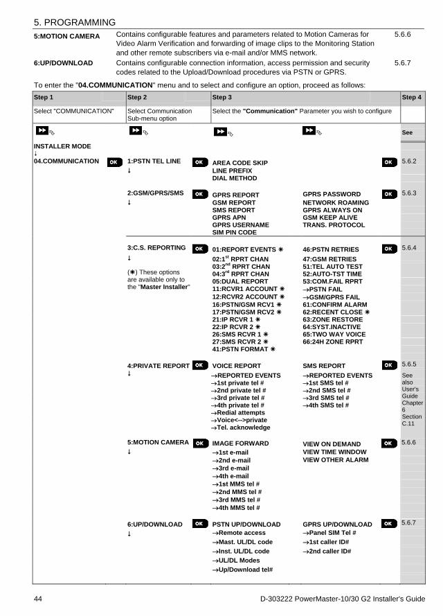
5. PROGRAMMING
44 D-303222 PowerMaster-10/30 G2 Installer's Guide
5:MOTION CAMERA Contains configurable features and parameters related to Motion Cameras for
Video Alarm Verification and forwarding of image clips to the Monitoring Station
and other remote subscribers via e-mail and/or MMS network.
5.6.6
6:UP/DOWNLOAD Contains configurable connection information, access permission and security
codes related to the Upload/Download procedures via PSTN or GPRS.
5.6.7
To enter the "04.COMMUNICATION" menu and to select and configure an option, proceed as follows:
Step 1 Step 2 Step 3 Step 4
Select "COMMUNICATION" Select Communication Sub-menu option
Select the "Communication" Parameter you wish to configure
See
INSTALLER MODE 04.COMMUNICATION
1:PSTN TEL LINE
AREA CODE SKIP 5.6.2
LINE PREFIX DIAL METHOD 2:GSM/GPRS/SMS
GPRS REPORT GPRS PASSWORD 5.6.3
GSM REPORT NETWORK ROAMING SMS REPORT GPRS ALWAYS ON GPRS APN GSM KEEP ALIVE GPRS USERNAME TRANS. PROTOCOL SIM PIN CODE
3:C.S. REPORTING
01:REPORT EVENTS 46:PSTN RETRIES 5.6.4
02:1st
RPRT CHAN 47:GSM RETRIES
() These options are available only to the "Master Installer"
03:2nd
RPRT CHAN 51:TEL AUTO TEST 04:3
rd RPRT CHAN 52:AUTO-TST TIME
05:DUAL REPORT 53:COM.FAIL RPRT 11:RCVR1 ACCOUNT PSTN FAIL
12:RCVR2 ACCOUNT GSM/GPRS FAIL
16:PSTN/GSM RCV1 61:CONFIRM ALARM 17:PSTN/GSM RCV2 62:RECENT CLOSE 21:IP RCVR 1 63:ZONE RESTORE 22:IP RCVR 2 64:SYST.INACTIVE 26:SMS RCVR 1 65:TWO WAY VOICE 27:SMS RCVR 2 66:24H ZONE RPRT 41:PSTN FORMAT
4:PRIVATE REPORT VOICE REPORT SMS REPORT 5.6.5
REPORTED EVENTS REPORTED EVENTS See also User's Guide Chapter 6 Section C.11
1st private tel # 1st SMS tel # 2nd private tel # 2nd SMS tel # 3rd private tel # 3rd SMS tel # 4th private tel # 4th SMS tel # Redial attempts Voice<-->private Tel. acknowledge 5:MOTION CAMERA
IMAGE FORWARD VIEW ON DEMAND 5.6.6
1st e-mail VIEW TIME WINDOW
2nd e-mail VIEW OTHER ALARM
3rd e-mail
4th e-mail
1st MMS tel #
2nd MMS tel #
3rd MMS tel #
4th MMS tel #
6:UP/DOWNLOAD PSTN UP/DOWNLOAD GPRS UP/DOWNLOAD 5.6.7
Remote access Panel SIM Tel #
Mast. UL/DL code 1st caller ID#
Inst. UL/DL code 2nd caller ID#
UL/DL Modes
Up/Download tel#

5. PROGRAMMING
D-303222 PowerMaster-10/30 G2 Installer's Guide 45
5.6.2 Configuring PSTN (landline phone) Connection The PowerMaster panels include a telephone dialer for reporting to Monitoring Stations using several optional Alarm
Formats (see section 5.6.4 option 41) and to Private Telephones (see section 5.6.5 "VOICE REPORT"). Here you
configure necessary parameters related to the PSTN telephone line to which the PowerMaster is connected.
04:COMMUNICATION 1:PSTN TEL LINE MENU you wish
Enter "1:PSTN TEL LINE", select the menu you wish to configure (see guidance above and in section 5.6.1), then refer
to the table below.
Option Configuration Instructions
AREA CODE SKIP In some older PSTN networks, it may not be possible to dial from the control panel to other
PSTN telephone numbers (such as monitoring stations or private phones), if the dialed
number contains an area code which is identical to the area code of the panel (i.e. both the
panel and the other numbers are in the same PSTN area code).
If you encounter the same problem with the PSTN network the panel is connected to, you
must enter here the area code of the PSTN telephone line to which the panel is connected (up
to 4 digits) so that when dialing to other PSTN phone numbers programmed with the same
area code, the PowerMaster will skip the area code from the dialed number.
LINE PREFIX Enter the prefix digit (if necessary) for the system to access an outside telephone line. DIAL METHOD Define the dialing method used by the PSTN dialer of the PowerMaster control panel.
Options: pulse and tone (dtmf) (default).
5.6.3 Configuring GSM-GPRS (IP) - SMS Cellular Connection The GSM/GPRS module is capable of communicating with the Monitoring station receiver by GPRS, GSM Voice
(analog) or SMS Channels.
Each of the channels can be separately enabled or disabled to allow or prohibit the module from using it for the event
reporting. If all channels are enabled, the GSM/GPRS module will always try GPRS first. If fails, it will try GSM voice. If
fails, it will try any other possible method (PSTN Broadband) and only then it will try SMS. Disabling any of the GSM
channels will cause the module to use a different sequence than the one described above.
04:COMMUNICATION 2:GSM/GPRS/SMS MENU you wish
Enter "2:GSM/GPRS/SMS", select the menu you wish to configure (see guidance above and in section 5.6.1), then
refer to the table below which provides you with detailed explanations and configuration instructions for each option.
Option Configuration Instructions
GPRS REPORT Define whether the system will report events to the Monitoring Stations' PowerManage
receivers via the GPRS (IP) Channel. For further information, see section 5.6.4 options 21 & 22.
Options: disable (default); enable.
Note: This feature cannot be enabled in UL Listed product. GSM REPORT Define whether the system will report events to the Monitoring Stations' Alarm Format
receivers via the GSM Voice (analog) Channel. For further information, see section 5.6.4
option 41.
Options: disable (default); enable. SMS REPORT Define whether the system will report events to the Monitoring Stations' SMS receivers via
the SMS Channel. For further information, see section 5.6.4 options 26 & 27.
Options: disable (default); enable. GPRS APN Enter the name of the APN Access Point used for the internet settings for the GPRS (up to
40 digits string).
Note: To enter the APN Access Point, use the "String Editor" at the end of this section.
GPRS USERNAME Enter the Username of the APN used for GPRS communications (up to 30 digits string).
Note: To enter the Username, use the "String Editor" at the end of this section.
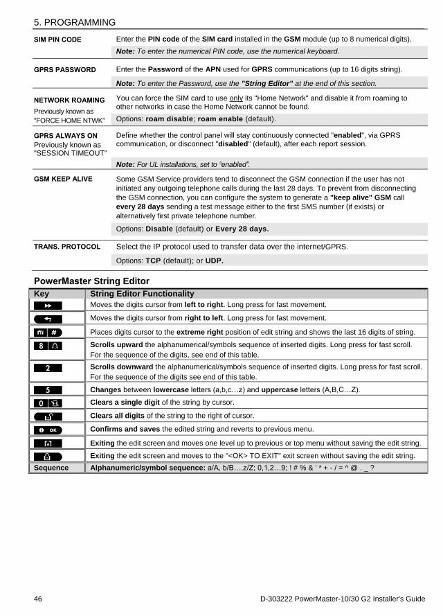
5. PROGRAMMING
46 D-303222 PowerMaster-10/30 G2 Installer's Guide
SIM PIN CODE Enter the PIN code of the SIM card installed in the GSM module (up to 8 numerical digits).
Note: To enter the numerical PIN code, use the numerical keyboard.
GPRS PASSWORD Enter the Password of the APN used for GPRS communications (up to 16 digits string).
Note: To enter the Password, use the "String Editor" at the end of this section.
NETWORK ROAMING
Previously known as
"FORCE HOME NTWK"
You can force the SIM card to use only its "Home Network" and disable it from roaming to other networks in case the Home Network cannot be found.
Options: roam disable; roam enable (default). GPRS ALWAYS ON
Previously known as "SESSION TIMEOUT"
Define whether the control panel will stay continuously connected "enabled", via GPRS
communication, or disconnect "disabled" (default), after each report session.
Note: For UL installations, set to “enabled”. GSM KEEP ALIVE Some GSM Service providers tend to disconnect the GSM connection if the user has not
initiated any outgoing telephone calls during the last 28 days. To prevent from disconnecting
the GSM connection, you can configure the system to generate a "keep alive" GSM call
every 28 days sending a test message either to the first SMS number (if exists) or
alternatively first private telephone number.
Options: Disable (default) or Every 28 days.
TRANS. PROTOCOL Select the IP protocol used to transfer data over the internet/GPRS.
Options: TCP (default); or UDP.
PowerMaster String Editor
Key String Editor Functionality
Moves the digits cursor from left to right. Long press for fast movement.
Moves the digits cursor from right to left. Long press for fast movement.
Places digits cursor to the extreme right position of edit string and shows the last 16 digits of string.
Scrolls upward the alphanumerical/symbols sequence of inserted digits. Long press for fast scroll.
For the sequence of the digits, see end of this table.
Scrolls downward the alphanumerical/symbols sequence of inserted digits. Long press for fast scroll.
For the sequence of the digits see end of this table.
Changes between lowercase letters (a,b,c…z) and uppercase letters (A,B,C…Z).
Clears a single digit of the string by cursor.
Clears all digits of the string to the right of cursor.
Confirms and saves the edited string and reverts to previous menu.
Exiting the edit screen and moves one level up to previous or top menu without saving the edit string.
Exiting the edit screen and moves to the "<OK> TO EXIT" exit screen without saving the edit string.
Sequence Alphanumeric/symbol sequence: a/A, b/B….z/Z; 0,1,2…9; ! # % & ' * + - / = ^ @ . _ ?
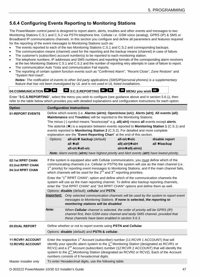
5. PROGRAMMING
D-303222 PowerMaster-10/30 G2 Installer's Guide 47
5.6.4 Configuring Events Reporting to Monitoring Stations
The PowerMaster control panel is designed to report alarm, alerts, troubles and other events and messages to two
Monitoring Stations C.S.1 and C.S.2 via PSTN telephone line, Cellular i.e. GSM voice (analog), GPRS (IP) & SMS or
Broadband IP communications channels. In this section you configure and define all parameters and features required
for the reporting of the event messages to Monitoring Stations such as:
The events reported to each of the two Monitoring Stations C.S.1 and C.S.2 and corresponding backups.
The communication means (channel) used for the reporting and the backup means (channel) in case of failure.
The customer's (subscriber) account number(s) to be reported to each monitoring station.
The telephone numbers, IP addresses and SMS numbers and reporting formats of the corresponding alarm receivers at the two Monitoring Stations C.S.1 and C.S.2 and the number of reporting retry attempts in case of failure to report.
The communication Auto Tests and communication Fail reports.
The reporting of certain system function events such as "Confirmed Alarm", "Recent Close", Zone Restore" and "System Not-Used".
Notes: The notification of events to other 3rd party applications (SMS/IP/personal phones) is a supplementary feature that has not been investigated by UL and is not used in UL listed installations.
04:COMMUNICATION 3:C.S.REPORTING MENU you wish
Enter "3:C.S.REPORTING", select the menu you wish to configure (see guidance above and in section 5.6.1), then
refer to the table below which provides you with detailed explanations and configuration instructions for each option.
Option Configuration Instructions
01:REPORT EVENTS Define which events (i.e. Alarms (alrm); Open/close (o/c); Alerts (alrt); All events (all);
Maintenance and Troubles) will be reported to the Monitoring Stations.
The minus (-) symbol means "less/except" e.g. all(-alrt) means all events except alerts.
The asterisk () is a separator between events reported to Monitoring Station 1 (C.S.1) and
events reported to Monitoring Station 2 (C.S.2). For detailed and more complete
explanation see the "Event Reporting Chart" at the end of this section.
Options: all-o/c backup (default) all-o/co/c disable report
all all all(-alrt)alrt all backup
all-o/call-o/c alrmall(-alrm)
Note: Alarm events (alrm) have highest priority and Alert events (alrt) have lowest priority.
02:1st RPRT CHAN
03:2nd RPRT CHAN
04:3rd RPRT CHAN
If the system is equipped also with Cellular communicators, you must define which of the
communicating channels (i.e. Cellular or PSTN) the system will use as the main channel (i.e.
1st priority) for reporting event messages to Monitoring Stations, and if the main channel fails,
which channels will be used for the 2nd
and 3rd
reporting priorities.
Enter the "1st RPRT CHAN"; option and define which of the communication channels the
system will use as the main reporting channel. To define also backup reporting channels,
enter the "2nd RPRT CHAN" and "3rd RPRT CHAN" options and define them as well.
Options: disable (default); cellular and PSTN.
Important: Only selected communication channels will be used by the system to report event
messages to Monitoring Stations. If none is selected, the reporting to
monitoring stations will be disabled.
Note:
When Cellular channel is selected, the order of priority will be GPRS (IP)
channel first, then GSM voice channel and lastly SMS channel, provided that
these channels have been enabled in section 5.6.3. 05:DUAL REPORT Define whether or not to report events using PSTN and Cellular.
Options: disable (default) and PSTN & cellular. 11:RCVR1 ACCOUNT
12:RCVR2 ACCOUNT
Enter the respective 1st Account (subscriber) number (11:RCVR 1 ACCOUNT) that will
identify your specific alarm system to the 1st Monitoring Station (designated as RCVR1 or
RCV1) and a 2nd
Account (subscriber) number (12:RCVR 2 ACCOUNT) that will identify the
system to the 2nd
Monitoring Station (designated as RCVR2 or RCV2). Each of the Account
numbers consists of 6 hexadecimal digits.
Master Installer only To enter Hexadecimal digits, use the following table:
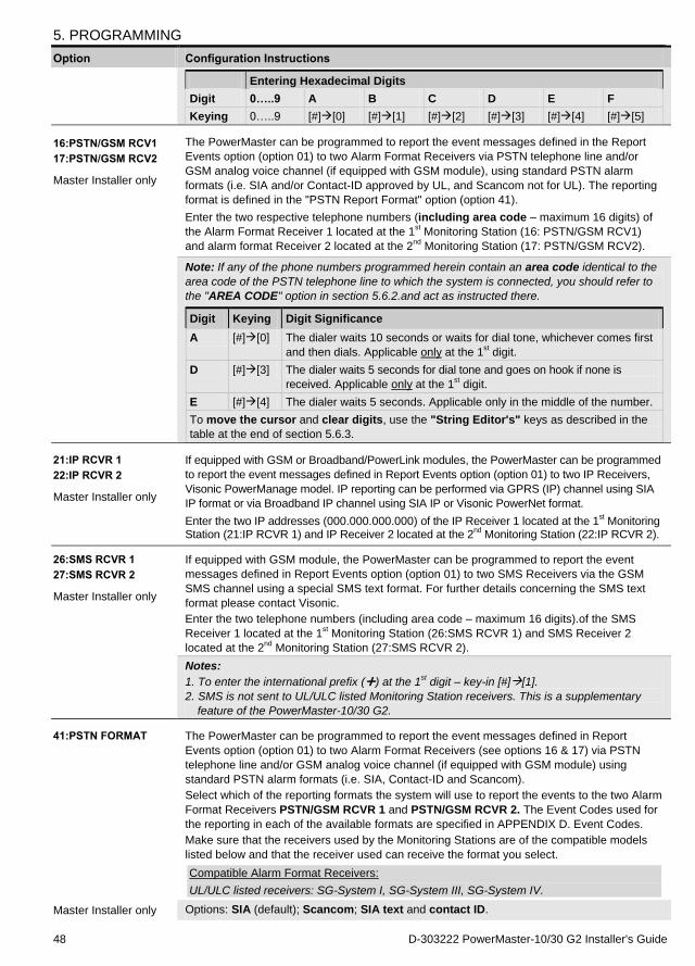
5. PROGRAMMING
48 D-303222 PowerMaster-10/30 G2 Installer's Guide
Option Configuration Instructions
Entering Hexadecimal Digits
Digit 0…..9 A B C D E F
Keying 0…..9 [#][0] [#][1] [#][2] [#][3] [#][4] [#][5]
16:PSTN/GSM RCV1
17:PSTN/GSM RCV2
Master Installer only
The PowerMaster can be programmed to report the event messages defined in the Report
Events option (option 01) to two Alarm Format Receivers via PSTN telephone line and/or
GSM analog voice channel (if equipped with GSM module), using standard PSTN alarm
formats (i.e. SIA and/or Contact-ID approved by UL, and Scancom not for UL). The reporting
format is defined in the "PSTN Report Format" option (option 41).
Enter the two respective telephone numbers (including area code – maximum 16 digits) of
the Alarm Format Receiver 1 located at the 1st Monitoring Station (16: PSTN/GSM RCV1)
and alarm format Receiver 2 located at the 2nd
Monitoring Station (17: PSTN/GSM RCV2).
Note: If any of the phone numbers programmed herein contain an area code identical to the
area code of the PSTN telephone line to which the system is connected, you should refer to
the "AREA CODE" option in section 5.6.2.and act as instructed there.
Digit Keying Digit Significance
A [#][0] The dialer waits 10 seconds or waits for dial tone, whichever comes first
and then dials. Applicable only at the 1st digit.
D [#][3] The dialer waits 5 seconds for dial tone and goes on hook if none is
received. Applicable only at the 1st digit.
E [#][4] The dialer waits 5 seconds. Applicable only in the middle of the number.
To move the cursor and clear digits, use the "String Editor's" keys as described in the
table at the end of section 5.6.3.
21:IP RCVR 1
22:IP RCVR 2
Master Installer only
If equipped with GSM or Broadband/PowerLink modules, the PowerMaster can be programmed
to report the event messages defined in Report Events option (option 01) to two IP Receivers,
Visonic PowerManage model. IP reporting can be performed via GPRS (IP) channel using SIA
IP format or via Broadband IP channel using SIA IP or Visonic PowerNet format.
Enter the two IP addresses (000.000.000.000) of the IP Receiver 1 located at the 1st Monitoring
Station (21:IP RCVR 1) and IP Receiver 2 located at the 2nd
Monitoring Station (22:IP RCVR 2). 26:SMS RCVR 1
27:SMS RCVR 2
Master Installer only
If equipped with GSM module, the PowerMaster can be programmed to report the event
messages defined in Report Events option (option 01) to two SMS Receivers via the GSM
SMS channel using a special SMS text format. For further details concerning the SMS text
format please contact Visonic.
Enter the two telephone numbers (including area code – maximum 16 digits).of the SMS
Receiver 1 located at the 1st Monitoring Station (26:SMS RCVR 1) and SMS Receiver 2
located at the 2nd
Monitoring Station (27:SMS RCVR 2).
Notes:
1. To enter the international prefix () at the 1st digit – key-in [#][1].
2. SMS is not sent to UL/ULC listed Monitoring Station receivers. This is a supplementary
feature of the PowerMaster-10/30 G2. 41:PSTN FORMAT The PowerMaster can be programmed to report the event messages defined in Report
Events option (option 01) to two Alarm Format Receivers (see options 16 & 17) via PSTN
telephone line and/or GSM analog voice channel (if equipped with GSM module) using
standard PSTN alarm formats (i.e. SIA, Contact-ID and Scancom).
Select which of the reporting formats the system will use to report the events to the two Alarm
Format Receivers PSTN/GSM RCVR 1 and PSTN/GSM RCVR 2. The Event Codes used for
the reporting in each of the available formats are specified in APPENDIX D. Event Codes.
Make sure that the receivers used by the Monitoring Stations are of the compatible models
listed below and that the receiver used can receive the format you select.
Compatible Alarm Format Receivers:
UL/ULC listed receivers: SG-System I, SG-System III, SG-System IV.
Master Installer only Options: SIA (default); Scancom; SIA text and contact ID.

5. PROGRAMMING
D-303222 PowerMaster-10/30 G2 Installer's Guide 49
Option Configuration Instructions
Note: For UL installations, the communication formats used are SIA and Contact ID and the
compatible receivers are the ones mentioned above. 46:PSTN RETRIES Define the number of times the system will retry to report to the Monitoring Station in case of
failure to report via the PSTN telephone line connection.
Options: 2 attempts; 4 attempts (default); 8 attempts; 12 attempts and 16 attempts.
Note: For UL Listed product, set to "8 attempts". 47:GSM RETRIES Define the number of times the system will retry to report to the Monitoring Station in case of
failure to report via the cellular connection - GPRS (IP), GSM and SMS.
Options: 2 attempts; 4 attempts (default); 8 attempts; 12 attempts and 16 attempts.
Note: For UL Listed product, set to "8 attempts". 51:TEL AUTO TEST To verify a proper communication channel, the PowerMaster can be configured to send a test
event to the Monitoring Station via PSTN periodically. You can set the interval between the
consecutive test events or disable the automatic sending of this event entirely. If the interval is
set for every one day or more then the exact hour of reporting can be selected with option 52.
Options: test OFF (default); every 1/2/5/7/14/30 day(s); and every 5 hours.
Note: For UL Listed product, set to “every 1 day”. 52:AUTO TST TIME Enter the exact time (auto test time) during the day at which the Auto Test message (if
enabled in option 51) will be sent to the Monitoring Station.
Note: If the AM/PM format is used, you can set the "AM" digit with the button and
the "PM" digit with the button.
53:COM.FAIL RPRT
PSTN FAIL
GSM/GPRS FAIL
(Return)
Determine whether a failure in any of the system communication channels i.e. PSTN or
GSM/GPRS will be reported or not and the time delay between detection of the failure and
reporting of the failure event to the Monitoring Station. A trouble event (i.e. "tel line fail" or
"GSM line fail") will be respectively stored in the event log.
Previously known as "LINE FAIL REPORT"
Options "PSTN FAIL": immediat report (default); after 5/30/60/180 min; and do not report.
Options "GSM/GPRS FAIL": after 2/5/15/30 min and do not report (default). 62:RECENT CLOSE
False alarms may occur if users do not exit the premises within the exit delay period,
resulting in a false alarm a short time later. In such cases, inform the Monitoring Station that
the alarm occurred shortly after the system was armed (this event is known as "Recent
Close"). The report enabled option sends a “recent closing” report to the Monitoring Station if
an alarm occurs within 2 minutes from the end of the exit delay.
Options: report disabled (default) and report enabled
Notes:
1. CP-01 was tested and certified by ETL/Intertek.
2. CP-01 features not to be enabled in UL Listed product. 63:ZONE RESTORE Some Monitoring Stations require that following an alarm event from a specific zone, the
system will also report when the alarming zone has restored to normal.
Options: report enabled (default) and report disabled 64:SYST.INACTIVE The PowerMaster can report a "System Inactive" event message (CID event 654) to the
Monitoring Station if the system is not used (i.e. armed) during a predefined time period.
Options: report disabled (default); after 7/14/30/90 days.
65:TWO WAY VOICE1
Send 2wv code
You can configure the two way voice channel settings of the control panel1, as follows:
Send 2 WV Code: Define whether the system will send two-way voice code to the Monitoring
1 Refers to PowerMaster-30 G2 with voice option only
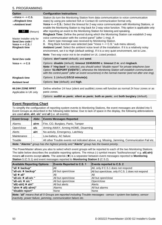
5. PROGRAMMING
50 D-303222 PowerMaster-10/30 G2 Installer's Guide
Option Configuration Instructions
Voice <- -> C.S.
Ringback time
Ambient level
(Return)
Master Installer only for Send 2wv code / Voice <--> C.S. / Ringback time
Station (to turn the Monitoring Station from data communication to voice communication
state) by using pre-selected SIA or Contact-ID communication format only.
Voice <--> C.S.: Select the timeout for 2-way voice communication with Monitoring Stations, or
enable the Monitoring Station to ring back for 2-way voice function. This option is applicable only
after reporting an event to the Monitoring Station for listening and speaking.
Ringback Time: Define the period during which the Monitoring Station can establish 2-way
voice communication with the control panel1 (after 1 ring), if:
A. Alarm type message was received by Monitoring Station. B. Ring Back function was selected (see “Voice <--> C.S.” sub menu above).
Ambient Level: Select the ambient noise level of the installation. If it is a relatively noisy
environment, set it to High (default setting). If it is a very quiet environment, set to Low.
Note: Two-way voice not to be enabled on UL Listed product.
Send 2wv code Options: don’t send (default); and send.
Voice <- -> C.S Options: disable (default); timeout 10/45/60/90 s; timeout 2 m; and ringback.
Note: If "ring back" is selected, you should select "disable report" for private telephone (see
Option "01:REPORT EVENTS"), otherwise the Monitoring Station will establish communication with the control panel
1 (after an event occurrence) in the normal manner (and not after one ring).
Ringback time Options: 1 (default)/3/5/10 minute(s).
Ambient level Options: low (default); and high.
66:24H ZONE RPRT
Applicable in UK only
Define whether 24 hour (silent and audible) zones will function as normal 24 hour zones or as
panic zones.
Options: audibl as panic; silent as panic; both as panic; and both burglary (default).
Event Reporting Chart To simplify the configuration of reporting system events to Monitoring Stations, the event messages are divided into 5 Event Groups as described in the following table below: Due to lack of space in the display, the following abbreviations are used alrm, alrt, o/c” and all (i.e. all events).
Event Group Abbr. Events Messages Reported
Alarms alrm Fire, CO, Burglary, Panic, Tamper
Open/close o/c Arming AWAY, Arming HOME, Disarming
Alerts alrt No-activity, Emergency, Latchkey
Maintenance - Low-battery, AC failure
Trouble - All other Trouble events not indicated above, e.g. Missing, Jamming, Communication Fail etc.
Note: "Alarms" group has the highest priority and "Alerts" group has the lowest priority.
The PowerMaster allows you also to select which event groups will be reported to each of the two Monitoring Stations.
The table below describes the available reporting options. The minus (-) symbol means "but/less/except" e.g. all(-alrt)
means all events except alerts. The asterisk () is a separator between event messages reported to Monitoring
Station 1 (C.S.1) and event messages reported to Monitoring Station 2 (C.S.2).
Available Reporting Options Events Reported to C.S. 1 Events reported to C.S. 2
"all backup" All All, only if C.S.1 does not respond "all-o/c backup" All but open/close All but open/close, only if C.S. 1 does not respond "all all" All All "all-o/c all-o/c " All but open/close All but open/close "all–o/c o/c " All but open/close Open/close "all(–alrt) alrt" All but alerts Alerts "alrm all(–alrm)" Alarms All but alarms "disable report" None None
Note: “all” means that all 5 Groups are reported including Trouble messages - sensor / system low battery, sensor
inactivity, power failure, jamming, communication failure etc.
5. PROGRAMMING
D-303222 PowerMaster-10/30 G2 Installer's Guide 51
5.6.5 Configuring Events Reporting to Private Users The PowerMaster system can be programmed to send various event notifications such as alarm, arming or trouble
events, to 4 Private telephone subscribers using audible signals and if a GSM option is installed, the system can send
the messages also to 4 SMS telephone numbers. These reports can be programmed either instead of or in addition to
the reports transmitted to the monitoring company. In this section you configure:
The specific events you wish the system to report.
The 1st, 2
nd, 3
rd, and 4
th Private telephone and SMS numbers of the private subscribers.
The number of redial attempts, two-way voice communication1 and your preferred acknowledge method i.e.
whether a single acknowledge signal will stop the reporting process or an acknowledge signal from each telephone will be required before the reported event is considered reported.
To select and configure an option follow the instructions below. Additional guidance is provided in section 5.6.1.
04:COMMUNICATION 4:PRIVATE REPORT MENU you wish
The "4:PRIVATE REPORT" menus and sub-menus configuration is shown in the table in section 5.6.1. For a detailed
description of the menus options, refer to the User's Guide Chapter 6, section C.11.
5.6.6 Configuring Motion Cameras for Visual Alarm Verification
If equipped with a GSM/GPRS module, the PowerMaster can communicate to Monitoring Stations (equipped with
Visonic PowerManage server) via the GPRS network, also with image clips captured by Motion Cameras (models Next
CAM PG2 & Next-K9 CAM PG2). The Monitoring Station can use the video clips for verification of Burglary alarms
detected by the Motion Cameras. The system can be configured to capture image clips also upon occurrence of Non-
Burglary alarms (i.e. Fire, Duress, Emergency and Panic). The server can then forward the images to the management
computer of the monitoring station or to 4 remote computers via e-mail and/or 4 mobile phones by MMS images.
In addition, the monitoring station can log into the PowerManage server and request the system to provide image clips
"On Demand" and to forward them as defined in the PowerManage application. To protect customers' privacy, the
PowerMaster can be customized to enable the "On Demand View" only during specific system modes (i.e. Disarm,
Home and Away) and also to a specific time window following an alarm event. In this section you can program the 4
e-mail addresses and mobile phone numbers to which the images will be forwarded and to configure the parameters of
the "On Demand View".
Note: Motion cameras are not to be enabled in UL Listed products.
04:COMMUNICATION 5:MOTION CAMERAS MENU you wish
Enter "5:MOTION CAMERAS", select the menu you wish to configure (see guidance above and in section 5.6.1), then
refer to the table below which provides you with detailed configuration instructions.
Option Configuration Instructions
IMAGE FORWARD 1st e-mail 2nd e-mail 3rd e-mail 4th e-mail 1st MMS tel # 2nd MMS tel # 3rd MMS tel # 4th MMS tel #
Enter the four e-mail addresses and/or 4 mobile phone numbers intended for the
PowerManage server to forward the image clips captured by the Motion Cameras.
To program:
Press to enter the "IMAGE FORWARD" sub menu and then select and program each of
the four e-mail numbers and then each of the four mobile phone numbers. When done, press to return.
Enter the 1st, 2
nd, 3
rd and 4
th e-mail addresses (see note below) then enter the 1
st, 2
nd, 3
rd and
4th mobile phone numbers ("1st MMS tel #" etc.)
Note: To enter the e-mail addresses, to move the cursor and clear digits, use the "String
Editor's" keys as described in the table at the end of section 5.6.3. VIEW ON DEMAND By enabling the "On Demand View", you can determine during which arming modes (system
states) the "On Demand View" will be permitted. In the next option "VIEW TIME WINDOW"
you can determine when, during the permitted arming modes, the "On Demand View" will be
enabled.
Options: disabled (default); in all modes; in AWAY only; in HOME only; in HOME &
AWAY; DISARM & AWAY; DISARM & HOME; and in DISARM only.
1 Refers to PowerMaster-30 G2 with voice option only
5. PROGRAMMING
52 D-303222 PowerMaster-10/30 G2 Installer's Guide
Option Configuration Instructions
VIEW TIME WINDOW
“VIEW TIME WINDOW” menu appears only if an option other than
"Disabled" is selected in “VIEW ON DEMAND”
If the "On Demand View" is enabled in the previous option, you can further determine whether
the "On Demand View" will be possible at any time during the selected arming modes (i.e.
"Always") or restricted only to a specific limited time window that follows an alarm event.
Options: Always (default); Alarm + 5 min.; Alarm + 15 min.; Alarm + 1 hour
VIEW OTHER ALARM Define whether the system will capture and forward image clips also upon occurrence of Non-
Burglary alarms (i.e. Fire, Duress, Emergency and panic).
Options: Enable (default); Disable.
5.6.7 Configuring Upload / Download Remote Programming Access Permission
Using a PC computer, the PowerMaster can be configured (by upload/download) either locally or from remote via
PSTN telephone line or GPRS cellular communication.
Note: For UL installations, do not enable Remote Programming via GPRS. Local programming can be performed by direct connecting the computer to the panel's serial port using the Remote Programmer PC Software.
Remote programming via PSTN can be performed by using a modem and the same software. The modem dials to
the control panel and establishes a connection via PSTN using an agreed process. When connection is established,
the installer or Master installer can access the panel using the UL/DL access codes programmed in the
"PSTN UP/DOWNLOAD" menu – see table below. For further information refer to the "PowerMaster Remote
Programmer Software User's Guide".
Remote programming via GPRS is performed using a Visonic PowerManage server and related Remote Programmer
PC software. The PowerManage server calls from a cellular modem to the Panel's SIM card number. The panel checks
the caller ID and if identical with any of the two callers ID 1 or 2 programmed in the "GPRS UP/DOWNLOAD" menu
(see table below), the panel initiates a GPRS connection with the respective IP Receiver 1 or 2 (as configured in
section 5.6.4 options 21 & 22). When connection is established, the monitoring company can perform the
upload/download procedure via the established secured GPRS connection. For further information refer to the
PowerManage User's Guide
In this section you can configure the access permissions (i.e. security codes and identification) and determine the
functionality of the upload/download procedures via PSTN and GPRS channels.
04:COMMUNICATION 6:UP/DOWNLOAD MENU you wish
Enter "6:UP/DOWNLOAD", select the menu to configure (see guidance above and in section 5.6.1), then refer to the
table below for configuration instructions.
Option Configuration Instructions
PSTN UP/DOWNLOAD Configure the Upload/Download functionality via PSTN. The functionality is determined
through a sub-menu of the "PSTN UP/DOWNLOAD" option as shown below.
To program:
Press to enter the "PSTN UP/DOWNLOAD" sub menu and then select and configure
each of the sub-menu options as shown below. When done, press to return.
Remote access Enable or disable the remote access to the system. If disabled, the system cannot be
accessed remotely thereby inhibiting the Upload/Download and the Remote Control via
PSTN or GSM analog communication channels (see Chapter 7 in the User's Guide).
Options: enabled (default); disabled.
Mast. UL/DL code Enter the 4-digit password (Master Installer download code) code that will allow the Master
Installer to access the system remotely and upload/download data to the PowerMaster panel.
Note: "0000" is not a valid code and must not be used.
Inst. UL/DL code Enter the 4-digit password (Installer download code) code that will allow the Installer to
access the system from remote and upload or download data into the PowerMaster panel.
Notes:
"0000" is not a valid code and must not be used.
The installer can configure via UL/DL only the options he is authorized to configure from the control panel.
5. PROGRAMMING
D-303222 PowerMaster-10/30 G2 Installer's Guide 53
Option Configuration Instructions
UL/DL modes
Define whether the downloading/uploading can be performed in Disarm mode (state) only or
in all modes (i.e. Away, Home & Disarm).
Options: in all modes (default) or in DISARM only.
Up/Download tel#
Enter the telephone number (up to 16 digits) of the UL/DL server.
Note: Only for use with control panels monitored by compatible monitoring stations. Leave
empty if not used.
(Return)
GPRS UP/DOWNLOAD Configure the Upload/Download functionality via GPRS. The functionality is determined
through a sub-menu of the "GPRS UP/DOWNLOAD" option as shown below.
To program:
Press to enter the "GPRS UP/DOWNLOAD" sub menu and then select and configure each of the sub-menu options as shown below. When done, press to return.
Panel SIM Tel.#
Previously known as "My SIM Tel.#"
Enter the PowerMaster SIM card telephone number. The PowerManage server at the
Monitoring Station sends an SMS message to this number for the panel to call back the
PowerManage server via GPRS for initiating the uploading / downloading process.
Enter the SIM card telephone number of the panel's GSM module.
1st caller ID#
2nd caller ID#
Enter the "Caller ID" (i.e. telephone number) from which Monitoring Station #1 (C.S.1) /
Monitoring Station #2 (C.S.2) calls the control panel for initiating the Up/Download process.
If the sender's Caller ID matches with the "1st caller ID#" / "2
nd caller ID#", the PowerMaster
will call back the PowerManage server using "IP RCVR 1" / "IP RCVR 2" address as
configured in Section 5.6.4, options 21 and 22.
Note: Caller ID#1/ID#2 must contain at least 6 digits otherwise the process will not work.
(Return)
5.7 PGM Output
5.7.1 General Guidance The "05:OUTPUTS" menu enables you to select events/conditions under which the PGM (programmable) output will function and to select the internal siren or STROBE light (that will be activated according to system programming).
1
05:OUTPUS PGM DEVICES PGM DEVICE 01 MENU you wish
Enter "PGM DEVICE 01", select the menu you wish to configure (see guidance above and in section 5.2), and then
refer to the table in section 5.7.5 for configuration instructions.
Note: PGM not to be enabled in UL Listed Product.
5.7.2 Open Collector States
The PowerMaster provides an open collector output (active low) for control:
ON state (pulled to ground) = 0
OFF state:
no pullup = float
with pullup to Vcc = 1
5.7.3 Configuring a PGM device Define which factors, including any combination of factors, will determine the PGM output.
5.7.4 Entering Daytime Limits
05:OUTPUS PGM DEVICES LOCKOUT TIME
Enter the "LOCKOUT TIME" menu and enter the daytime limits through which the PGM device will turn off, even when
the associated sensors are triggered.
1 In PowerMaster-10 G2, this is always available. In PowerMaster-30 G2, this is optional only when the expansion module is installed.
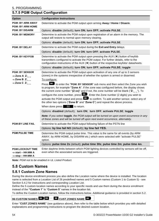
5. PROGRAMMING
54 D-303222 PowerMaster-10/30 G2 Installer's Guide
5.7.5 PGM Output Configuration
Option Configuration Instructions
PGM: BY ARM AWAY
PGM: BY ARM HOME
PGM: BY DISARM
Determine to activate the PGM output upon arming Away / Home / Disarm.
Options: disable (default); turn ON; turn OFF; activate PULSE.
PGM: BY MEMORY Determine to activate the PGM output upon registration of an alarm in the memory. The
output will restore to normal upon memory clearing.
Options: disable (default); turn ON; turn OFF; activate PULSE.
PGM: BY DELAY Determine to activate the PGM output during the Exit and Entry delays.
Options: disable (default); turn ON; turn OFF; activate PULSE.
PGM: BY KEYFOB Determine to activate the PGM output upon pressing the AUX () button of keyfob
transmitters configured to activate the PGM output. For further details, refer to the
configuration instructions of the AUX () button of the respective keyfobs' datasheets.
Options: disable (default); turn ON; turn OFF; activate PULSE; toggle
PGM: BY SENSOR
Zone A Z:_ _
Zone B Z:_ _
Zone C Z:_ _
Determine to activate the PGM output upon activation of any one of up to 3 sensors
(zones) in the systems irrespective of whether the system is armed or disarmed.
To configure:
Press to enter the "PGM: BY SENSOR" sub menu and then select the Zone you wish
to program, for example "Zone A". If the zone was configured before, the display shows
the current zone number "(Z:xx)" and if not, the zone number will be blank ("Z:_ _"). To
configure the zone number, press . Enter the Zone number (2 digits) you wish to
activate the PGM output and press to confirm. To add another sensor, select any of
the other two options ("Zone B" and "Zone C") and repeat the above process.
When done press to return.
Options: disabled (default); turn ON; turn OFF; activate PULSE; toggle
Note: If you select toggle, the PGM output will be turned on upon event occurrence in any
of these zones and will be turned off upon next event occurrence, alternately.
PGM:BY LINE FAIL Determine to activate the PGM output following failure of the PSTN line
Options: by line fail NO (default); by line fail YES.
PGM:PULSE TIME Determine the PGM output pulse time. This value is the same for all events (by ARM
AWAY, by ARM HOME, by DISARM etc.) which were selected with "activate PULSE"
option.
Options: pulse time 2s (default); pulse time 30s; pulse time 2m; pulse time 4m.
PGM:LOCKOUT TIME
start – HH:MM A
stop – HH:MM A
Enter daytime limits between which PGM lighting devices controlled by sensors will be off,
even when the associated sensors are triggered.
Note: PGM not to be enabled in UL Listed Product.
5.8 Custom Names
5.8.1 Custom Zone Names During the device enrollment process you also define the Location name where the device is installed. The location
name is selected from a Location List of 26 predefined names and 5 Custom names (Custom 1 to Custom 5) - see
Section 5.4.2 for instructions and corresponding Location List.
Define the 5 custom location names according to your specific needs and use them during the device enrollment
instead of the “Custom 1” to “Custom 5” names in the location list.
To define the Custom Location names, follow the instructions below. Additional guidance is provided in section 5.2.
06:CUSTOM NAMES CUST.ZONES NAME
Enter "CUST.ZONES NAME" (see guidance above), then refer to the table below which provides you with detailed
explanations and programming instructions to program the desired custom location.

5. PROGRAMMING
D-303222 PowerMaster-10/30 G2 Installer's Guide 55
Option Configuration Instructions
CUST. ZONES NAME
TEXT LOC. #05 1
TEXT LOC. #05 2
TEXT LOC. #05 3
TEXT LOC. #05 4
TEXT LOC. #05 5
Enter the five Custom Location names you wish to use instead of the "Custom 1" to
"Custom 5" names in the Location List in Section 5.4.2.
To program:
Press to enter the "CUST. ZONES NAME" sub menu and then press again to
select the Location # you wish to program, for example "TEXT LOC. #05 1". Press ; the
display shows the current Custom name, for example "Custom 1". To change the name, at
the blinking cursor, enter the Location name you wish and at the end, press to confirm.
When done, press to return.
Note: To enter the Location name use the "String Editor" at the end of section 5.6.3.
5.8.2 Record Speech1
You can record short-duration speech messages for the house identity, user names and custom zone names.
For the recording procedure follow the instructions below. Additional details and guidance are provided in section 5.2.
06:CUSTOM NAMES RECORD SPEECH
Enter "RECORD SPEECH", select the menu you wish to perform (see guidance above), then refer to the tables below
which provide you with detailed explanations for each option.
Option Instructions
HOUSE IDENTITY You can record a message to be announced automatically when events are reported to
private telephones.
While in "RECORD SPEECH", press ; the display now reads "HOUSE IDENTITY" and
alternates with "REC-<2> PLAY-<5>" (this means, press the button to record and the
button to play recording).
To initiate the recording procedure, press the button continuously to record your
message; "RECORD A MESSAGE" appears momentarily and then changes to "TALK NOW" (the square boxes slowly disappear, one by one, until the end of the
recording time).
At the end of the recording process, the panel will display the following:
"RECORDING ENDED". Release the button.
Note: To check the recorded message, press the button and listen to the playback.
To advance to the next stage in the recording procedure; from the "HOUSE IDENTITY" menu, click .
Option Instructions
USER #23 VOICE You can record ten user names and assign them to users 23-32. In case of event, the
relevant user name will be added to the message that will be reported via the telephone.
Record user names for 23-32; the procedure is identical to the "HOUSE IDENTITY" recording
procedure described above. Click to navigate between user name numbers.
VOICE LOC. #1 You can record user terms 1- 5 (for example, Living room, Library, etc.), and assign them to
specific zones. These names are useful if none of the 26 fixed zone names are found suitable for a certain zone. When done, press to return.
Record user terms 1-5; the procedure is identical to the "HOUSE IDENTITY" recording
procedure described above. Click to navigate between user term numbers.
1 Refers to PowerMaster-30 G2 with voice option only

5. PROGRAMMING
56 D-303222 PowerMaster-10/30 G2 Installer's Guide
5.8.3 Voice Box Mode1
This mode allows you to determine whether two-way voice communication is to be sounded either via an external
speakerphone, via the control panel, or via both.
For the two-way voice communication procedure, follow the instructions below. Additional details and guidance are
provided in section 5.2.
06:CUSTOM NAMES VOICE BOX MODE
Enter "VOICE BOX MODE", and then refer to the table below which provides you with the options.
VOICE BOX MODE Define whether two-way voice communication is to be sounded either via the external
speakerphone ("VOICE BOX ONLY"), via the control panel ("NO VOICE BOX"), or via both
("VOICE BOX MIXED").
Options: NO VOICE BOX; VOICE BOX ONLY and VOICE BOX MIXED (default)
5.9 Diagnostics
5.9.1 General Guidance – "Diagnostics" Flow-Chart & Menu Options The DIAGNOSTICS menu enables you to test your system and to verify proper operation of your PowerMaster panel, wireless devices attached to it and the communication (GSM/GPRS) modules.
IMPORTANT! Reliable reception must be assured during the initial testing and also throughout subsequent system maintenance. A device should not be installed in location where signal strength is "poor". If you get "poor" signal strength from a certain device, simply re-locate it and re-test until a "good" or "strong" signal strength is received. This principle should be followed throughout the diagnostic test procedure.
Note: For UL installations, "strong" signal strength for WL Devices is required.
The diagnostic test process is shown below.
The "07.DIAGNOSTICS" menu contains several sub-menu options, each covering a group of configurable features and parameters related to the communication and reporting as follows (see the list in Step 3 of the chart below):
Option Description of Option Features and Parameters Section
WL DEVICES Describes how to test the devices attached to the PowerMaster panel, review devices' status and RF signal status. You can test all devices, test single device, review devices status and review RF problems, in case of any.
5.9.2
GSM/GPRS Describes how to test the GSM/GPRS communication module. 5.9.3
To enter the "07.DIAGNOSTICS" menu and to select and configure an option, proceed as follows:
Step 1 Step 2 Step 3 Step 4
Select "07.DIAGNOSTICS" Select sub-menu option Select the diagnostics you want to perform
See
INSTALLER MODE
07.DIAGNOSTICS WL DEVICES TEST ALL DEVICES 5.9.2
SHOW ALL DEVICES
SHOW RF PROBLEMS
TEST ONE DEVICE Contact sensors Motion sensors
Repeaters
GSM/GPRS 5.9.3
5.9.2 Testing Wireless Devices
The PowerMaster enable to test the wireless devices attached to the panel. You can test all devices, one device at a
time, display devices' status and review RF problems, in case of any.
07:DIAGNOSTICS WL DEVICES MENU you wish
Enter the "WL DEVICES" menu, select the type of test you wish to perform (see guidance above and in section 5.9.1),
then refer to the table below which provides you with detailed explanations for each option.
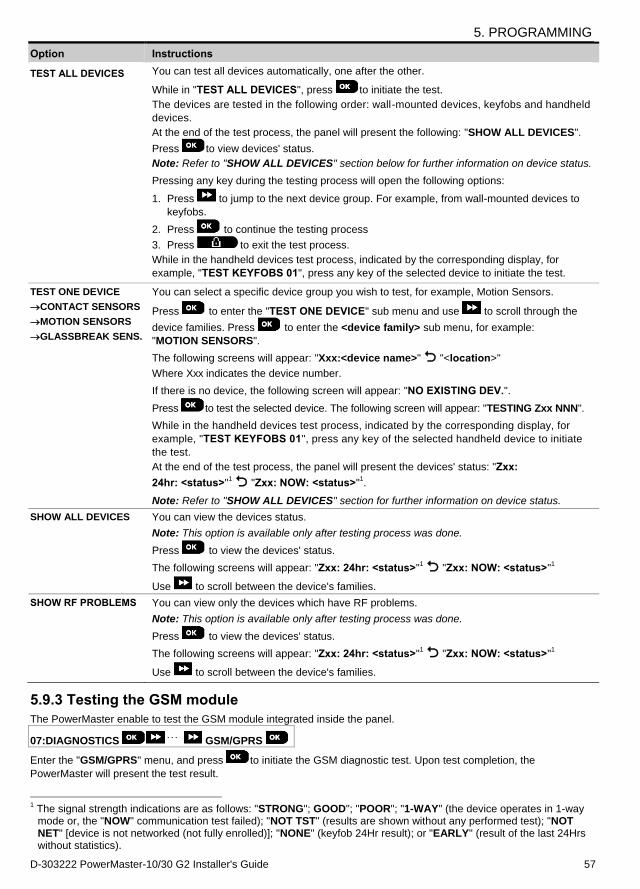
5. PROGRAMMING
D-303222 PowerMaster-10/30 G2 Installer's Guide 57
Option Instructions
TEST ALL DEVICES You can test all devices automatically, one after the other.
While in "TEST ALL DEVICES", press to initiate the test.
The devices are tested in the following order: wall-mounted devices, keyfobs and handheld
devices.
At the end of the test process, the panel will present the following: "SHOW ALL DEVICES".
Press to view devices' status.
Note: Refer to "SHOW ALL DEVICES" section below for further information on device status.
Pressing any key during the testing process will open the following options:
1. Press to jump to the next device group. For example, from wall-mounted devices to
keyfobs.
2. Press to continue the testing process
3. Press to exit the test process.
While in the handheld devices test process, indicated by the corresponding display, for
example, "TEST KEYFOBS 01", press any key of the selected device to initiate the test.
TEST ONE DEVICE
CONTACT SENSORS
MOTION SENSORS
GLASSBREAK SENS.
You can select a specific device group you wish to test, for example, Motion Sensors.
Press to enter the "TEST ONE DEVICE" sub menu and use to scroll through the
device families. Press to enter the <device family> sub menu, for example:
"MOTION SENSORS".
The following screens will appear: "Xxx:<device name>" "<location>"
Where Xxx indicates the device number.
If there is no device, the following screen will appear: "NO EXISTING DEV.".
Press to test the selected device. The following screen will appear: "TESTING Zxx NNN".
While in the handheld devices test process, indicated by the corresponding display, for
example, "TEST KEYFOBS 01", press any key of the selected handheld device to initiate
the test.
At the end of the test process, the panel will present the devices' status: "Zxx:
24hr: <status>"1 "Zxx: NOW: <status>"
1.
Note: Refer to "SHOW ALL DEVICES" section for further information on device status.
SHOW ALL DEVICES You can view the devices status.
Note: This option is available only after testing process was done.
Press to view the devices' status.
The following screens will appear: "Zxx: 24hr: <status>"1 "Zxx: NOW: <status>"
1
Use to scroll between the device's families.
SHOW RF PROBLEMS You can view only the devices which have RF problems.
Note: This option is available only after testing process was done.
Press to view the devices' status.
The following screens will appear: "Zxx: 24hr: <status>"1 "Zxx: NOW: <status>"
1
Use to scroll between the device's families.
5.9.3 Testing the GSM module
The PowerMaster enable to test the GSM module integrated inside the panel.
07:DIAGNOSTICS GSM/GPRS
Enter the "GSM/GPRS" menu, and press to initiate the GSM diagnostic test. Upon test completion, the
PowerMaster will present the test result.
1 The signal strength indications are as follows: "STRONG"; GOOD"; "POOR"; "1-WAY" (the device operates in 1-way mode or, the "NOW" communication test failed); "NOT TST" (results are shown without any performed test); "NOT NET" [device is not networked (not fully enrolled)]; "NONE" (keyfob 24Hr result); or "EARLY" (result of the last 24Hrs without statistics).
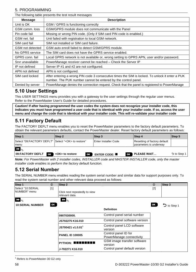
5. PROGRAMMING
58 D-303222 PowerMaster-10/30 G2 Installer's Guide
The following table presents the test result messages
Message Description
Unit is OK GSM / GPRS is functioning correctly
GSM comm. loss GSM/GPRS module does not communicate with the Panel
Pin code fail Missing or wrong PIN code. (Only if SIM card PIN code is enabled.)
GSM net. fail Unit failed with registration to local GSM network.
SIM card fail SIM not installed or SIM card failure.
GSM not detected GSM auto enroll failed to detect GSM/GPRS module.
No GPRS service The SIM card does not have the GPRS service enabled.
GPRS conn. fail Local GPRS network is not available or, wrong setting to GPRS APN, user and/or password.
Srvr unavailable PowerManage receiver cannot be reached – Check the Server IP
IP not defined Server IP #1 and #2 are not configured.
APN not defined APN is not configured.
SIM card locked After entering a wrong PIN code 3 consecutive times the SIM is locked. To unlock it enter a PUK
number. The PUK number cannot be entered by the control panel.
Denied by server PowerManage denies the connection request. Check that the panel is registered to PowerManage
5.10 User Settings This USER SETTINGS menu provides you with a gateway to the user settings through the regular user menus.
Refer to the PowerMaster User's Guide for detailed procedures.
Caution! If after having programmed the user codes the system does not recognize your installer code, this indicates you must have programmed a user code that is identical with your installer code. If so, access the user menu and change the code that is identical with your installer code. This will re-validate your installer code
5.11 Factory Default The FACTORY DEFLT menu enables you to reset the PowerMaster parameters to the factory default parameters. To obtain the relevant parameters defaults, contact the PowerMaster dealer. Reset factory default parameters as follows:
Step 1 Step 2 Step 3 Step 4 Step 5
Select "09:FACTORY DEFLT" menu
Select "<OK> to restore" Enter Installer Code Resetting of factory default parameters is underway
09:FACTORY DEFLT <OK> to restore
ENTER CODE: PLEASE WAIT… to Step 1
Note: For PowerMaster with 2 installer codes, INSTALLER code and MASTER INSTALLER code, only the master
installer code enables to perform the factory default function.
5.12 Serial Number The SERIAL NUMBER menu enables reading the system serial number and similar data for support purposes only. To
read the system serial number and other relevant data proceed as follows:
Step 1 Step 2
Step 3
Select "10:SERIAL NUMBER" menu
[1]
Click next repeatedly to view relevant data.
[2]
10:SERIAL NUMBER to Step 1
Definition 0907030000. Control panel serial number JS702275 K16.010 Control panel software version
JS700421 v1.0.011
Control panel LCD software version
PANEL ID 100005
Control panel ID for PowerManage connectivity
PYTHON:
GSM image transfer software version
J-702271 K16.010 Control panel default version
1 Refers to PowerMaster-30 G2 only
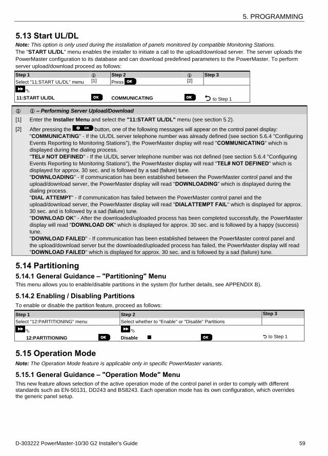
5. PROGRAMMING
D-303222 PowerMaster-10/30 G2 Installer's Guide 59
5.13 Start UL/DL Note: This option is only used during the installation of panels monitored by compatible Monitoring Stations.
The "START UL/DL" menu enables the installer to initiate a call to the upload/download server. The server uploads the
PowerMaster configuration to its database and can download predefined parameters to the PowerMaster. To perform
server upload/download proceed as follows:
Step 1 Step 2 Step 3
Select "11:START UL/DL" menu [1] Press [2]
11:START UL/DL COMMUNICATING to Step 1
– Performing Server Upload/Download
[1] Enter the Installer Menu and select the "11:START UL/DL" menu (see section 5.2).
[2] After pressing the button, one of the following messages will appear on the control panel display:
"COMMUNICATING" - If the UL/DL server telephone number was already defined (see section 5.6.4 "Configuring
Events Reporting to Monitoring Stations"), the PowerMaster display will read "COMMUNICATING" which is
displayed during the dialing process.
"TEL# NOT DEFINED" - If the UL/DL server telephone number was not defined (see section 5.6.4 "Configuring
Events Reporting to Monitoring Stations"), the PowerMaster display will read "TEL# NOT DEFINED" which is
displayed for approx. 30 sec. and is followed by a sad (failure) tune.
"DOWNLOADING" - If communication has been established between the PowerMaster control panel and the
upload/download server, the PowerMaster display will read "DOWNLOADING" which is displayed during the
dialing process.
"DIAL ATTEMPT" - If communication has failed between the PowerMaster control panel and the
upload/download server, the PowerMaster display will read "DIALATTEMPT FAIL" which is displayed for approx.
30 sec. and is followed by a sad (failure) tune.
"DOWNLOAD OK" - After the downloaded/uploaded process has been completed successfully, the PowerMaster
display will read "DOWNLOAD OK" which is displayed for approx. 30 sec. and is followed by a happy (success)
tune.
"DOWNLOAD FAILED" - If communication has been established between the PowerMaster control panel and
the upload/download server but the downloaded/uploaded process has failed, the PowerMaster display will read
"DOWNLOAD FAILED" which is displayed for approx. 30 sec. and is followed by a sad (failure) tune.
5.14 Partitioning
5.14.1 General Guidance – "Partitioning" Menu This menu allows you to enable/disable partitions in the system (for further details, see APPENDIX B).
5.14.2 Enabling / Disabling Partitions
To enable or disable the partition feature, proceed as follows:
Step 1 Step 2 Step 3
Select "12:PARTITIONING" menu Select whether to "Enable" or "Disable" Partitions
12:PARTITIONING Disable to Step 1
5.15 Operation Mode Note: The Operation Mode feature is applicable only in specific PowerMaster variants.
5.15.1 General Guidance – "Operation Mode" Menu
This new feature allows selection of the active operation mode of the control panel in order to comply with different standards such as EN-50131, DD243 and BS8243. Each operation mode has its own configuration, which overrides the generic panel setup.
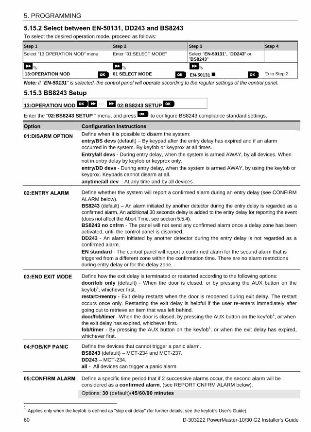
5. PROGRAMMING
60 D-303222 PowerMaster-10/30 G2 Installer's Guide
5.15.2 Select between EN-50131, DD243 and BS8243
To select the desired operation mode, proceed as follows:
Step 1 Step 2 Step 3 Step 4
Select "13:OPERATION MOD" menu Enter "01:SELECT MODE" Select "EN-50131", "DD243" or "BS8243"
13:OPERATION MOD
01 SELECT MODE EN-50131
to Step 2
Note: If "EN-50131" is selected, the control panel will operate according to the regular settings of the control panel.
5.15.3 BS8243 Setup
13:OPERATION MOD 02:BS8243 SETUP
Enter the "02:BS8243 SETUP " menu, and press to configure BS8243 compliance standard settings.
Option Configuration Instructions
01:DISARM OPTION Define when it is possible to disarm the system:
entry/BS devs (default) – By keypad after the entry delay has expired and if an alarm
occurred in the system. By keyfob or keyprox at all times.
Entry/all devs - During entry delay, when the system is armed AWAY, by all devices. When
not in entry delay by keyfob or keyprox only.
entry/DD devs - During entry delay, when the system is armed AWAY, by using the keyfob or
keyprox. Keypads cannot disarm at all.
anytime/all dev – At any time and by all devices.
02:ENTRY ALARM Define whether the system will report a confirmed alarm during an entry delay (see CONFIRM
ALARM below).
BS8243 (default) – An alarm initiated by another detector during the entry delay is regarded as a
confirmed alarm. An additional 30 seconds delay is added to the entry delay for reporting the event
(does not affect the Abort Time, see section 5.5.4).
BS8243 no cnfrm - The panel will not send any confirmed alarm once a delay zone has been
activated, until the control panel is disarmed.
DD243 - An alarm initiated by another detector during the entry delay is not regarded as a
confirmed alarm.
EN standard - The control panel will report a confirmed alarm for the second alarm that is
triggered from a different zone within the confirmation time. There are no alarm restrictions
during entry delay or for the delay zone.
03:END EXIT MODE Define how the exit delay is terminated or restarted according to the following options:
door/fob only (default) - When the door is closed, or by pressing the AUX button on the
keyfob1, whichever first.
restart>reentry - Exit delay restarts when the door is reopened during exit delay. The restart
occurs once only. Restarting the exit delay is helpful if the user re-enters immediately after
going out to retrieve an item that was left behind.
door/fob/timer - When the door is closed, by pressing the AUX button on the keyfob1, or when
the exit delay has expired, whichever first.
fob/timer - By pressing the AUX button on the keyfob1, or when the exit delay has expired,
whichever first.
04:FOB/KP PANIC Define the devices that cannot trigger a panic alarm.
BS8243 (default) – MCT-234 and MCT-237.
DD243 – MCT-234.
all - All devices can trigger a panic alarm
05:CONFIRM ALARM Define a specific time period that if 2 successive alarms occur, the second alarm will be
considered as a confirmed alarm, (see REPORT CNFRM ALARM below).
Options: 30 (default)/45/60/90 minutes
1 Applies only when the keyfob is defined as "skip exit delay" (for further details, see the keyfob's User's Guide)
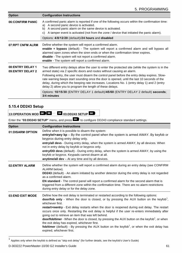
5. PROGRAMMING
D-303222 PowerMaster-10/30 G2 Installer's Guide 61
Option Configuration Instructions
06:CONFIRM PANIC A confirmed panic alarm is reported if one of the following occurs within the confirmation time: a) A second panic device is activated. b) A second panic alarm on the same device is activated.
c) A tamper event is activated (not from the zone / device that initiated the panic alarm).
Options: 4/8/12/20 (default)/24 hours and disabled
07:RPT CNFM ALRM Define whether the system will report a confirmed alarm.
enable + bypass (default) - The system will report a confirmed alarm and will bypass all
alarmed open zones when the siren ends or when the confirmation timer expires.
disable - The system will not report a confirmed alarm.
enable - The system will report a confirmed alarm.
08:ENTRY DELAY 1
09:ENTRY DELAY 2
Two different entry delays allow the user to enter the protected site (while the system is in the
armed state) via 2 specific doors and routes without causing an alarm.
Following entry, the user must disarm the control panel before the entry delay expires. Slow-
rate warning beeps start sounding once the door is opened, until the last 10 seconds of the
delay, during which the beeping rate increases. Locations No. 1 (entry delay 1) and 2 (entry
delay 2) allow you to program the length of these delays.
Options: 10/15/30 (ENTRY DELAY 1 default)/45/60 (ENTRY DELAY 2 default) seconds;
3/4 minutes
5.15.4 DD243 Setup
13:OPERATION MOD 03:DD243 SETUP
Enter the "03:DD243 SETUP" menu, and press to configure DD243 compliance standard settings.
Option Configuration Instructions
01:DISARM OPTION Define when it is possible to disarm the system:
entry/wl+awy kp – By the control panel when the system is armed AWAY. By keyfob or
keyprox during entry delay only.
entry/all devs - During entry delay, when the system is armed AWAY, by all devices. When
not in entry delay by keyfob or keyprox only.
entry/DD devs (default) - During entry delay, when the system is armed AWAY, by using the
keyfob or keyprox. Keypads cannot disarm at all.
anytime/all dev – At any time and by all devices.
02:ENTRY ALARM Define whether the system will report a confirmed alarm during an entry delay (see CONFIRM
ALARM below).
DD243 (default) - An alarm initiated by another detector during the entry delay is not regarded
as a confirmed alarm.
EN standard - The control panel will report a confirmed alarm for the second alarm that is
triggered from a different zone within the confirmation time. There are no alarm restrictions
during entry delay or for the delay zone.
03:END EXIT MODE Define how the exit delay is terminated or restarted according to the following options:
door/fob only - When the door is closed, or by pressing the AUX button on the keyfob1,
whichever first.
restart>reentry - Exit delay restarts when the door is reopened during exit delay. The restart
occurs once only. Restarting the exit delay is helpful if the user re-enters immediately after
going out to retrieve an item that was left behind.
door/fob/timer - When the door is closed, by pressing the AUX button on the keyfob1, or when
the exit delay has expired, whichever first.
fob/timer (default) - By pressing the AUX button on the keyfob1, or when the exit delay has
expired, whichever first.
1 Applies only when the keyfob is defined as "skip exit delay" (for further details, see the keyfob's User's Guide)

6. PERIODIC TEST
62 D-303222 PowerMaster-10/30 G2 Installer's Guide
Option Configuration Instructions
04:FOB/KP PANIC Define the devices that cannot trigger a panic alarm.
DD243 – MCT-234.
all - All devices can trigger a panic alarm
05:CONFIRM ALARM Define a specific time period that if 2 successive alarms occur, the second alarm will be
considered as a confirmed alarm, (see REPORT CNFRM ALARM below).
Options: 30/45/60 (default)/90 minutes
06:CONFIRM PANIC A confirmed panic alarm is reported if one of the following occurs within the confirmation time:
a) A second panic device is activated.
b) A second panic alarm on the same device is activated.
c) A tamper event is activated (not from the zone / device that initiated the panic alarm).
Options: 4/8/12/20 (default)/24 hours and disabled
07:RPT CNFM ALRM Define whether the system will report a confirmed alarm.
enable + bypass (default) - The system will report a confirmed alarm and will bypass all
alarmed open zones when the siren ends or when the confirmation timer expires.
disable - The system will not report a confirmed alarm.
enable - The system will report a confirmed alarm.
08:ENTRY DELAY 1
09:ENTRY DELAY 2
Two different entry delays allow the user to enter the protected site (while the system is in the
armed state) via 2 specific doors and routes without causing an alarm.
Following entry, the user must disarm the control panel before the entry delay expires. Slow-
rate warning beeps start sounding once the door is opened, until the last 10 seconds of the
delay, during which the beeping rate increases. Locations No. 1 (entry delay 1) and 2 (entry
delay 2) allow you to program the length of these delays.
Options: 10/15/30 (ENTRY DELAY 1 default)/45/60 (ENTRY DELAY 2 default) seconds;
3/4 minutes
6. PERIODIC TEST 6.1 General Guidance This mode provides you with the means to conduct a periodic test, via the "PERIODIC TEST" menu, at least once a
week and after an alarm event.
When you are instructed to perform a periodic test, walk throughout the site to check the detectors / sensors (except for
Sirens and Temperature Sensors). When a detector/sensor is triggered into alarm, its name, number and the alarm
reception level should be indicated (for example, "Bathroom", "Z19 strong") and the buzzer should sound according to
the alarm reception level (1 of 3). Each device should be tested according to the device Installation Instructions.
To enter the "PERIODIC TEST" menu and to conduct a periodic test, proceed as follows:
Step 1 Step 2
READY [1] Select the test to be performed [2]
PERIODIC TEST
(enter installer / master code)
SIRENS TEST
TEMPERATURE TEST
TEST ALL DEVICES
TEST ONE DEVICE
– Periodic Test
[1] Not including Siren and Temperature Sensors
[2] After reviewing all untested devices the control panel will read "<OK> TO LEAVE". You can now do one of the
following: press to abort the testing procedure; press to continue the testing procedure; or press
to exit the testing procedure.
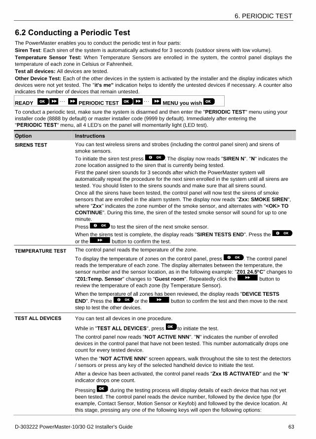
6. PERIODIC TEST
D-303222 PowerMaster-10/30 G2 Installer's Guide 63
6.2 Conducting a Periodic Test
The PowerMaster enables you to conduct the periodic test in four parts:
Siren Test: Each siren of the system is automatically activated for 3 seconds (outdoor sirens with low volume).
Temperature Sensor Test: When Temperature Sensors are enrolled in the system, the control panel displays the
temperature of each zone in Celsius or Fahrenheit.
Test all devices: All devices are tested.
Other Device Test: Each of the other devices in the system is activated by the installer and the display indicates which
devices were not yet tested. The "it's me" indication helps to identify the untested devices if necessary. A counter also
indicates the number of devices that remain untested.
READY PERIODIC TEST MENU you wish
To conduct a periodic test, make sure the system is disarmed and then enter the "PERIODIC TEST" menu using your
installer code (8888 by default) or master installer code (9999 by default). Immediately after entering the
"PERIODIC TEST" menu, all 4 LED's on the panel will momentarily light (LED test).
Option Instructions
SIRENS TEST You can test wireless sirens and strobes (including the control panel siren) and sirens of
smoke sensors.
To initiate the siren test press . The display now reads "SIREN N". "N" indicates the
zone location assigned to the siren that is currently being tested.
First the panel siren sounds for 3 seconds after which the PowerMaster system will
automatically repeat the procedure for the next siren enrolled in the system until all sirens are
tested. You should listen to the sirens sounds and make sure that all sirens sound.
Once all the sirens have been tested, the control panel will now test the sirens of smoke
sensors that are enrolled in the alarm system. The display now reads "Zxx: SMOKE SIREN",
where "Zxx" indicates the zone number of the smoke sensor, and alternates with "<OK> TO
CONTINUE". During this time, the siren of the tested smoke sensor will sound for up to one
minute.
Press to test the siren of the next smoke sensor.
When the sirens test is complete, the display reads "SIREN TESTS END". Press the
or the button to confirm the test.
TEMPERATURE TEST The control panel reads the temperature of the zone.
To display the temperature of zones on the control panel, press . The control panel
reads the temperature of each zone. The display alternates between the temperature, the
sensor number and the sensor location, as in the following example: "Z01 24.5C" changes to
"Z01:Temp. Sensor" changes to "Guest room". Repeatedly click the button to
review the temperature of each zone (by Temperature Sensor).
When the temperature of all zones has been reviewed, the display reads "DEVICE TESTS
END". Press the or the button to confirm the test and then move to the next
step to test the other devices.
TEST ALL DEVICES You can test all devices in one procedure.
While in "TEST ALL DEVICES", press to initiate the test.
The control panel now reads "NOT ACTIVE NNN". "N" indicates the number of enrolled
devices in the control panel that have not been tested. This number automatically drops one
count for every tested device.
When the "NOT ACTIVE NNN" screen appears, walk throughout the site to test the detectors
/ sensors or press any key of the selected handheld device to initiate the test.
After a device has been activated, the control panel reads "Zxx IS ACTIVATED" and the "N"
indicator drops one count.
Pressing during the testing process will display details of each device that has not yet
been tested. The control panel reads the device number, followed by the device type (for
example, Contact Sensor, Motion Sensor or Keyfob) and followed by the device location. At
this stage, pressing any one of the following keys will open the following options:
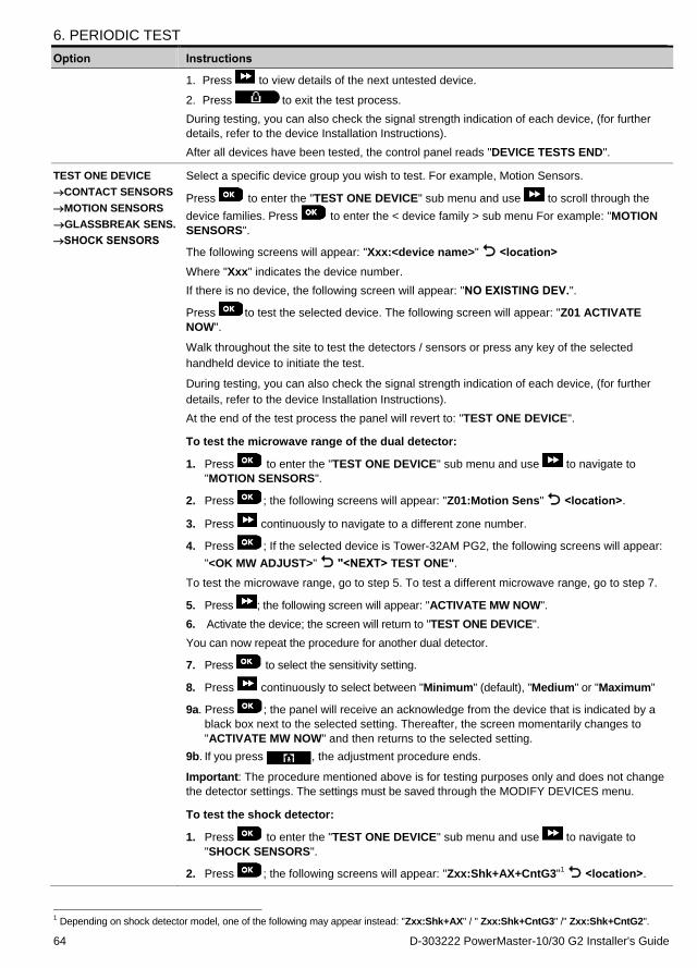
6. PERIODIC TEST
64 D-303222 PowerMaster-10/30 G2 Installer's Guide
Option Instructions
1. Press to view details of the next untested device.
2. Press to exit the test process.
During testing, you can also check the signal strength indication of each device, (for further
details, refer to the device Installation Instructions).
After all devices have been tested, the control panel reads "DEVICE TESTS END".
TEST ONE DEVICE
CONTACT SENSORS
MOTION SENSORS
GLASSBREAK SENS.
SHOCK SENSORS
Select a specific device group you wish to test. For example, Motion Sensors.
Press to enter the "TEST ONE DEVICE" sub menu and use to scroll through the
device families. Press to enter the < device family > sub menu For example: "MOTION
SENSORS".
The following screens will appear: "Xxx:<device name>" <location>
Where "Xxx" indicates the device number.
If there is no device, the following screen will appear: "NO EXISTING DEV.".
Press to test the selected device. The following screen will appear: "Z01 ACTIVATE
NOW".
Walk throughout the site to test the detectors / sensors or press any key of the selected
handheld device to initiate the test.
During testing, you can also check the signal strength indication of each device, (for further
details, refer to the device Installation Instructions).
At the end of the test process the panel will revert to: "TEST ONE DEVICE".
To test the microwave range of the dual detector:
1. Press to enter the "TEST ONE DEVICE" sub menu and use to navigate to
"MOTION SENSORS".
2. Press ; the following screens will appear: "Z01:Motion Sens" <location>.
3. Press continuously to navigate to a different zone number.
4. Press ; If the selected device is Tower-32AM PG2, the following screens will appear:
"<OK MW ADJUST>" "<NEXT> TEST ONE".
To test the microwave range, go to step 5. To test a different microwave range, go to step 7.
5. Press ; the following screen will appear: "ACTIVATE MW NOW".
6. Activate the device; the screen will return to "TEST ONE DEVICE".
You can now repeat the procedure for another dual detector.
7. Press to select the sensitivity setting.
8. Press continuously to select between "Minimum" (default), "Medium" or "Maximum"
9a. Press ; the panel will receive an acknowledge from the device that is indicated by a
black box next to the selected setting. Thereafter, the screen momentarily changes to
"ACTIVATE MW NOW" and then returns to the selected setting.
9b. If you press , the adjustment procedure ends.
Important: The procedure mentioned above is for testing purposes only and does not change
the detector settings. The settings must be saved through the MODIFY DEVICES menu.
To test the shock detector:
1. Press to enter the "TEST ONE DEVICE" sub menu and use to navigate to
"SHOCK SENSORS".
2. Press ; the following screens will appear: "Zxx:Shk+AX+CntG3"1 <location>.
1 Depending on shock detector model, one of the following may appear instead: "Zxx:Shk+AX" / " Zxx:Shk+CntG3" /" Zxx:Shk+CntG2".

7. MAINTENANCE
D-303222 PowerMaster-10/30 G2 Installer's Guide 65
Option Instructions
3. Press continuously to navigate to a different zone number.
4. Press ; the following screens will appear: "Zxx ACTIVATE NOW" "SHOCK NOT
ACTIV." "CNTACT NOT ACTIV" "AUXIL. NOT ACTIV".
Note: The above screens are the full range of screens that can appear and indicate the
inputs that have not yet been activated. However, since there are various models of the
shock detector, not all of these screens will appear on some models.
5. At this stage, activate each input of the shock detector in turn.
7. MAINTENANCE
7.1 Handling System Troubles
Fault What it means Solution
1-WAY The control panel cannot configure or control the device.
Battery consumption increases.
1. Make sure the device is physically present.
2. Check the display for device faults, for example, low battery.
3. Use RF diagnostics to check the current signal strength and during the last 24 hours.
4. Open the device cover and replace the battery or press the tamper switch.
5. Install the device in a different location.
6. Replace the device.
AC FAILURE There is no power to gas sensor Make sure that the AC power supply is connected properly
AC SUPPLY FAILURE
There is no power and the system is working on backup battery power
Make sure that the AC power supply is connected properly
CLEAN ME The fire detector must be cleaned Use a vacuum cleaner to clean the detector air vents occasionally to keep them free of dust.
COMM. FAILURE A message could not be sent to the monitoring station or to a private telephone (or a message was sent but was not acknowledged)
1. Check telephone cable connection
2. Check that correct telephone number has been dialed.
3. Dial Monitoring Station to check whether or not events are received.
CPU LOW BATTERY
The backup battery within the control panel is weak and must be replaced (see section 7.3, Replacing the Backup Battery).
1. Check for AC power is available in the Panel.
2. If trouble exists for more than 72 hours, replace the battery pack
CPU TAMPER OPEN
The control panel was physically tampered with or its cover was opened, or it was removed from wall.
The control panel is not closed properly. Open the control panel and then close it.
FUSE TROUBLE The PGM fuse is burnt out or overloaded. Make sure that the connection load conforms to that specified in the Specifications.
GAS TROUBLE Gas detector failure Gas detector: Disconnect and then put back the AC power supply connector
CO Gas detector: Replace the detector
GSM NET FAIL The GSM communicator is not able to connect to the cellular network.
1. Move the Panel and GSM unit to another location.
2. Enter and exit the installer menu
3. Disconnect GSM unit and install it again
4. Replace SIM card
5. Replace the GSM unit
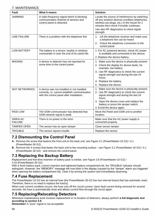
7. MAINTENANCE
66 D-303222 PowerMaster-10/30 G2 Installer's Guide
Fault What it means Solution
JAMMING A radio-frequency signal which is blocking communication channel of sensors and control panel is detected.
Locate the source of interference by switching off any wireless devices (cordless telephones, wireless ear plugs, etc.) in the house for 2 minutes then check if trouble continues.
Use also RF diagnostics to check signal strength.
LINE FAILURE There is a problem with the telephone line 1. Lift the telephone receiver and make sure a telephone line can be heard
2. Check the telephone connection to the control panel
LOW BATTERY The battery in a sensor, keyfob or wireless commander is near the end of its useful life.
1. For AC powered devices, check AC power is available and connected to the device.
2. Replace the device battery.
MISSING A device or detector has not reported for some time to the control panel.
1. Make sure the device is physically present.
2. Check the display for device faults, for example, low battery.
3. Use RF diagnostics to check the current signal strength and during the last 24 hours.
4. Replace the battery.
5. Replace the device.
NOT NETWORKED A device was not installed or not installed correctly, or, cannot establish communication with the control panel after installation.
1. Make sure the device is physically present.
2. Use RF diagnostics to check the current signal strength and during the last 24 hours.
3. Open the device cover and replace the battery or press the tamper switch.
4. Enroll the device again.
RSSI LOW The GSM communicator has detected that GSM network signal is weak
Move the Panel and GSM unit to another location.
SIREN AC FAILURE
There is no power to the siren Make sure that the AC power supply is connected properly
TAMPER OPEN The sensor has an open tamper Close sensor tamper
TROUBLE The sensor reports trouble Replace the sensor
7.2 Dismounting the Control Panel A. Remove the screw that fastens the front unit to the back unit, see Figure 3.1 (PowerMaster-10 G2) / 4.1
(PowerMaster-30 G2).
B. Remove the 4 screws that fasten the back unit to the mounting surface - see Figure 3.1 (PowerMaster-10 G2) / 4.1
(PowerMaster-30 G2) - and remove the control panel.
7.3 Replacing the Backup Battery Replacement and first-time insertion of battery pack is similar, see Figure 3.8 (PowerMaster-10 G2) / 4.10 (PowerMaster-30 G2). With a fresh battery pack, correct insertion and tightened battery compartment lid, the TROUBLE indicator should extinguish. However, the “MEMORY” message will now blink in the display (caused by the “tamper” alarm you triggered when opening the battery compartment lid). Clear it by arming the system and immediately disarming.
7.4 Fuse Replacement The PowerMaster-10 G2 has an internal fuse (the PowerMaster-30 G2 has two internal fuses) that has automatic reset. Therefore, there is no need to replace the fuse(s).
When over current condition occurs, the fuse cuts off the circuit current. Upon fault current being removed for several seconds, the fuse is automatically reset and allows current flow through the circuit again.
7.5 Replacing/Relocating Detectors Whenever maintenance work involves replacement or re-location of detectors, always perform a full diagnostic test according to section 5.9. Remember! A "poor" signal is not acceptable.
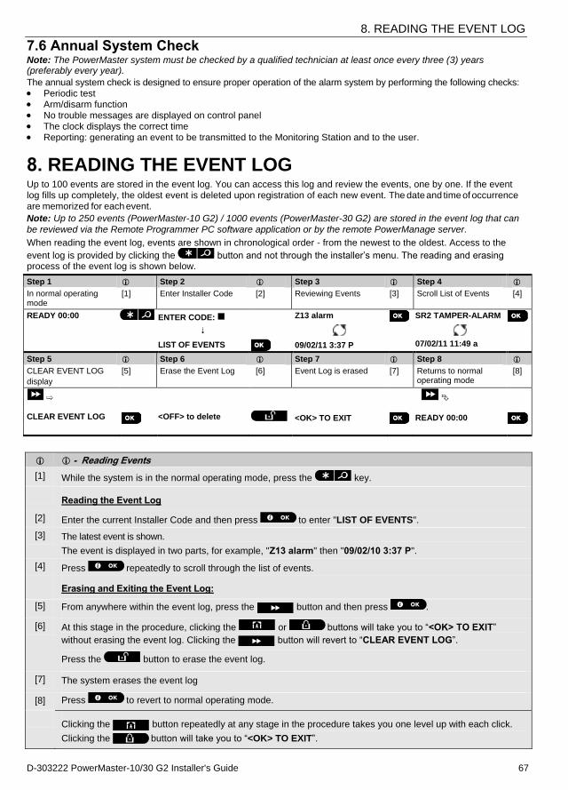
8. READING THE EVENT LOG
D-303222 PowerMaster-10/30 G2 Installer's Guide 67
7.6 Annual System Check Note: The PowerMaster system must be checked by a qualified technician at least once every three (3) years (preferably every year).
The annual system check is designed to ensure proper operation of the alarm system by performing the following checks: Periodic test Arm/disarm function No trouble messages are displayed on control panel The clock displays the correct time Reporting: generating an event to be transmitted to the Monitoring Station and to the user.
8. READING THE EVENT LOG Up to 100 events are stored in the event log. You can access this log and review the events, one by one. If the event log fills up completely, the oldest event is deleted upon registration of each new event. The date and time of occurrence
are memorized for each event.
Note: Up to 250 events (PowerMaster-10 G2) / 1000 events (PowerMaster-30 G2) are stored in the event log that can
be reviewed via the Remote Programmer PC software application or by the remote PowerManage server.
When reading the event log, events are shown in chronological order - from the newest to the oldest. Access to the
event log is provided by clicking the button and not through the installer’s menu. The reading and erasing process of the event log is shown below.
Step 1 Step 2 Step 3 Step 4
In normal operating mode
[1] Enter Installer Code [2] Reviewing Events [3] Scroll List of Events [4]
READY 00:00 ENTER CODE: Z13 alarm SR2 TAMPER-ALARM
LIST OF EVENTS 09/02/11 3:37 P 07/02/11 11:49 a
Step 5 Step 6 Step 7 Step 8
CLEAR EVENT LOG
display
[5] Erase the Event Log [6] Event Log is erased [7] Returns to normal operating mode
[8]
CLEAR EVENT LOG
<OFF> to delete <OK> TO EXIT READY 00:00
- Reading Events
[1] While the system is in the normal operating mode, press the key.
Reading the Event Log
[2] Enter the current Installer Code and then press to enter "LIST OF EVENTS".
[3] The latest event is shown.
The event is displayed in two parts, for example, "Z13 alarm" then "09/02/10 3:37 P".
[4] Press repeatedly to scroll through the list of events.
Erasing and Exiting the Event Log:
[5] From anywhere within the event log, press the button and then press .
[6] At this stage in the procedure, clicking the or buttons will take you to “<OK> TO EXIT”
without erasing the event log. Clicking the button will revert to “CLEAR EVENT LOG”.
Press the button to erase the event log.
[7] The system erases the event log
[8] Press to revert to normal operating mode.
Clicking the button repeatedly at any stage in the procedure takes you one level up with each click.
Clicking the button will take you to “<OK> TO EXIT”.
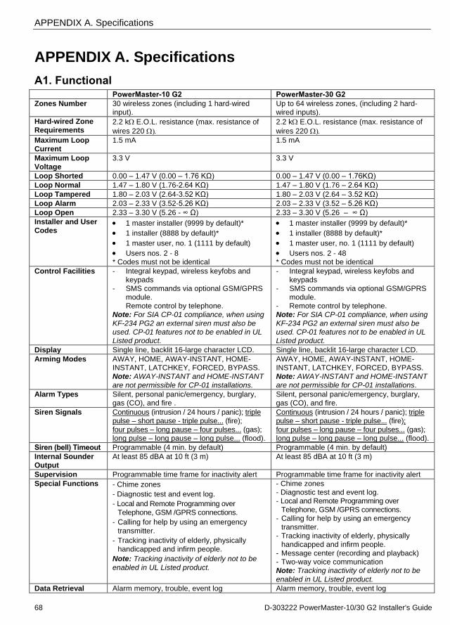
APPENDIX A. Specifications
68 D-303222 PowerMaster-10/30 G2 Installer's Guide
APPENDIX A. Specifications
A1. Functional PowerMaster-10 G2 PowerMaster-30 G2 Zones Number 30 wireless zones (including 1 hard-wired
input). Up to 64 wireless zones, (including 2 hard-wired inputs).
Hard-wired Zone Requirements
2.2 kE.O.L. resistance (max. resistance of
wires 220
2.2 kE.O.L. resistance (max. resistance of
wires 220
Maximum Loop Current
1.5 mA 1.5 mA
Maximum Loop Voltage
3.3 V 3.3 V
Loop Shorted 0.00 – 1.47 V (0.00 – 1.76 KΩ) 0.00 – 1.47 V (0.00 – 1.76KΩ)
Loop Normal 1.47 – 1.80 V (1.76-2.64 KΩ) 1.47 – 1.80 V (1.76 – 2.64 KΩ)
Loop Tampered 1.80 – 2.03 V (2.64-3.52 KΩ) 1.80 – 2.03 V (2.64 – 3.52 KΩ)
Loop Alarm 2.03 – 2.33 V (3.52-5.26 KΩ) 2.03 – 2.33 V (3.52 – 5.26 KΩ)
Loop Open 2.33 – 3.30 V (5.26 - ∞ Ω) 2.33 – 3.30 V (5.26 – ∞ Ω)
Installer and User Codes
1 master installer (9999 by default)*
1 installer (8888 by default)*
1 master user, no. 1 (1111 by default)
Users nos. 2 - 8 * Codes must not be identical
1 master installer (9999 by default)*
1 installer (8888 by default)*
1 master user, no. 1 (1111 by default)
Users nos. 2 - 48 * Codes must not be identical
Control Facilities - Integral keypad, wireless keyfobs and keypads
- SMS commands via optional GSM/GPRS module.
Remote control by telephone. Note: For SIA CP-01 compliance, when using
KF-234 PG2 an external siren must also be used. CP-01 features not to be enabled in UL Listed product.
- Integral keypad, wireless keyfobs and keypads
- SMS commands via optional GSM/GPRS module.
- Remote control by telephone. Note: For SIA CP-01 compliance, when using
KF-234 PG2 an external siren must also be used. CP-01 features not to be enabled in UL Listed product.
Display Single line, backlit 16-large character LCD. Single line, backlit 16-large character LCD.
Arming Modes AWAY, HOME, AWAY-INSTANT, HOME-INSTANT, LATCHKEY, FORCED, BYPASS. Note: AWAY-INSTANT and HOME-INSTANT
are not permissible for CP-01 installations.
AWAY, HOME, AWAY-INSTANT, HOME-INSTANT, LATCHKEY, FORCED, BYPASS. Note: AWAY-INSTANT and HOME-INSTANT are not permissible for CP-01 installations.
Alarm Types Silent, personal panic/emergency, burglary, gas (CO), and fire .
Silent, personal panic/emergency, burglary, gas (CO), and fire.
Siren Signals Continuous (intrusion / 24 hours / panic); triple pulse – short pause - triple pulse... (fire); four pulses – long pause – four pulses... (gas); long pulse – long pause – long pulse... (flood).
Continuous (intrusion / 24 hours / panic); triple pulse – short pause - triple pulse... (fire); four pulses – long pause – four pulses... (gas); long pulse – long pause – long pulse... (flood).
Siren (bell) Timeout Programmable (4 min. by default) Programmable (4 min. by default)
Internal Sounder Output
At least 85 dBA at 10 ft (3 m)
At least 85 dBA at 10 ft (3 m)
Supervision Programmable time frame for inactivity alert Programmable time frame for inactivity alert
Special Functions - Chime zones
- Diagnostic test and event log.
- Local and Remote Programming over
Telephone, GSM /GPRS connections.
- Calling for help by using an emergency
transmitter.
- Tracking inactivity of elderly, physically handicapped and infirm people.
Note: Tracking inactivity of elderly not to be
enabled in UL Listed product.
- Chime zones - Diagnostic test and event log. - Local and Remote Programming over
Telephone, GSM /GPRS connections. - Calling for help by using an emergency
transmitter. - Tracking inactivity of elderly, physically
handicapped and infirm people. - Message center (recording and playback) - Two-way voice communication Note: Tracking inactivity of elderly not to be
enabled in UL Listed product.
Data Retrieval Alarm memory, trouble, event log Alarm memory, trouble, event log
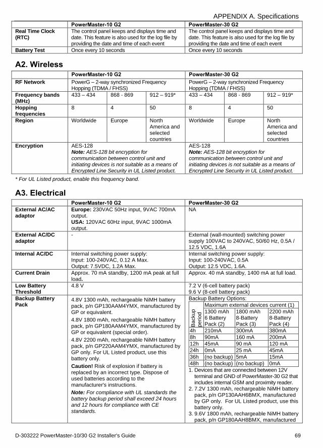
APPENDIX A. Specifications
D-303222 PowerMaster-10/30 G2 Installer's Guide 69
PowerMaster-10 G2 PowerMaster-30 G2 Real Time Clock (RTC)
The control panel keeps and displays time and date. This feature is also used for the log file by providing the date and time of each event
The control panel keeps and displays time and date. This feature is also used for the log file by providing the date and time of each event
Battery Test Once every 10 seconds Once every 10 seconds
A2. Wireless
PowerMaster-10 G2 PowerMaster-30 G2
RF Network PowerG – 2-way synchronized Frequency Hopping (TDMA / FHSS)
PowerG – 2-way synchronized Frequency Hopping (TDMA / FHSS)
Frequency bands (MHz)
433 – 434 868 - 869 912 – 919* 433 – 434 868 - 869 912 – 919*
Hopping frequencies
8 4 50 8 4 50
Region Worldwide Europe North America and selected countries
Worldwide Europe North America and selected countries
Encryption AES-128 Note: AES-128 bit encryption for
communication between control unit and initiating devices is not suitable as a means of Encrypted Line Security in UL Listed product.
AES-128 Note: AES-128 bit encryption for
communication between control unit and initiating devices is not suitable as a means of Encrypted Line Security in UL Listed product.
* For UL Listed product, enable this frequency band.
A3. Electrical PowerMaster-10 G2 PowerMaster-30 G2 External AC/AC adaptor
Europe: 230VAC 50Hz input, 9VAC 700mA output. USA: 120VAC 60Hz input, 9VAC 1000mA output.
NA
External AC/DC adaptor
- External (wall-mounted) switching power supply 100VAC to 240VAC, 50/60 Hz, 0.5A / 12.5 VDC, 1.6A
Internal AC/DC Internal switching power supply: Input: 100-240VAC, 0.12 A Max. Output: 7.5VDC, 1.2A Max.
Internal switching power supply: Input: 100-240VAC, 0.5A Output: 12.5 VDC, 1.6A.
Current Drain Approx. 70 mA standby, 1200 mA peak at full load.
Approx. 40 mA standby, 1400 mA at full load.
Low Battery Threshold
4.8 V 7.2 V (6-cell battery pack) 9.6 V (8-cell battery pack)
Backup Battery Pack
4.8V 1300 mAh, rechargeable NiMH battery
pack, p/n GP130AAM4YMX, manufactured by GP or equivalent.
4.8V 1800 mAh, rechargeable NiMH battery pack, p/n GP180AAM4YMX, manufactured by GP or equivalent (special order).
4.8V 2200 mAh, rechargeable NiMH battery pack, p/n GP220AAM4YMX, manufactured by GP only. For UL Listed product, use this battery only.
Caution! Risk of explosion if battery is replaced by an incorrect type. Dispose of used batteries according to the manufacturer's instructions.
Note: For compliance with UL standards the
battery backup period shall exceed 24 hours and 12 hours for compliance with CE standards.
Backup Battery Options:
Backup
period
Maximum external devices current (1) 1300 mAh 6 Battery Pack (2)
1800 mAh 8-Battery Pack (3)
2200 mAh 8-Battery Pack (4)
4h 210mA 300mA 380mA 8h 90mA 160 mA 200mA 12h 45mA 90 mA 120 mA 24h 0mA 25 mA 45mA 36h (no backup) 5mA 15mA 48h (no backup) (no backup) 0mA
1. Devices that are connected between 12V terminal and GND of PowerMaster-30 G2 that includes internal GSM and proximity reader.
2. 7.2V 1300 mAh, rechargeable NiMH battery pack, p/n GP130AAH6BMX, manufactured by GP only. For UL Listed product, use this battery only.
3. 9.6V 1800 mAh, rechargeable NiMH battery pack, p/n GP180AAH8BMX, manufactured
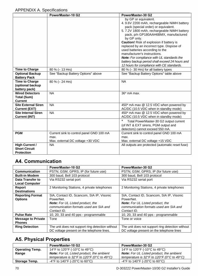
APPENDIX A. Specifications
70 D-303222 PowerMaster-10/30 G2 Installer's Guide
PowerMaster-10 G2 PowerMaster-30 G2 by GP or equivalent.
4. 9.6V 2200 mAh, rechargeable NiMH battery pack (special order) or equivalent.
5. 7.2V 1800 mAh, rechargeable NiMH battery pack, p/n GP180AAH6BMX, manufactured by GP only.
Caution! Risk of explosion if battery is replaced by an incorrect type. Dispose of used batteries according to the manufacturer's instructions. Note: For compliance with UL standards the
battery backup period shall exceed 24 hours and 12 hours for compliance with CE standards.
Time to Charge 80 % ( 13 Hrs) 80 % ( 30 Hrs) for all battery types
Optional Backup Battery Pack
See "Backup Battery Options" above See "Backup Battery Options" table above
Time to Charge (optional backup battery pack)
80 % ( 24 Hrs) NA
Wired Detectors Total (Sum) Current
NA 36* mA max.
Site External Siren Current (EXT)
NA 450* mA max @ 12.5 VDC when powered by AC/DC (10.5 VDC when in standby mode)
Site Internal Siren Current (INT)
NA 450* mA max @ 12.5 VDC when powered by AC/DC (10.5 VDC when in standby mode)
* Total PowerMaster-30 G2 output current
(of INT & EXT sirens, PGM output and detectors) cannot exceed 550 mA.
PGM Current sink to control panel GND 100 mA max. Max. external DC voltage +30 VDC
Current sink to control panel GND 100 mA max. Max. external DC voltage +15 VDC
High Current / Short Circuit Protection
NA All outputs are protected (automatic reset fuse)
A4. Communication PowerMaster-10 G2 PowerMaster-30 G2 Communication PSTN; GSM; GPRS; IP (for future use) PSTN; GSM; GPRS; IP (for future use) Built-in Modem 300 baud, Bell 103 protocol 300 baud, Bell 103 protocol Data Transfer to Local Computer
Via RS232 serial port Via RS232 serial port
Report Destinations
2 Monitoring Stations, 4 private telephones 2 Monitoring Stations, 4 private telephones
Reporting Format Options
SIA, Contact ID, Scancom, SIA IP, Visonic PowerNet. Note: For UL Listed product, the
communication formats used are SIA and Contact ID.
SIA, Contact ID, Scancom, SIA IP, Visonic PowerNet. Note: For UL Listed product, the
communication formats used are SIA and Contact ID.
Pulse Rate 10, 20, 33 and 40 pps - programmable 10, 20, 33 and 40 pps - programmable Message to Private Phones
Tone Tone or voice
Ring Detection The unit does not support ring detection without DC voltage present on the telephone lines.
The unit does not support ring detection without DC voltage present on the telephone lines
A5. Physical Properties PowerMaster-10 G2 PowerMaster-30 G2 Operating Temp. Range
14°F to 120°F (-10°C to 49°C) Note: For UL Listed product, the ambient
temperature is 32°F to 120°F (0°C to 49°C)
14°F to 120°F (-10°C to 49°C) Note: For UL Listed product, the ambient
temperature is 32°F to 120°F (0°C to 49°C) Storage Temp. -4°F to 140°F (-20°C to 60°C) -4°F to 140°F (-20°C to 60°C)
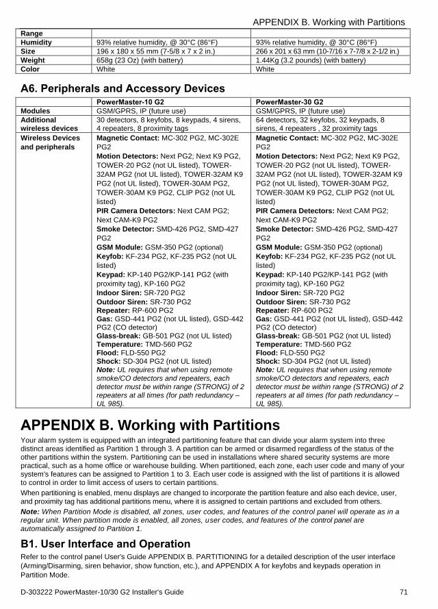
APPENDIX B. Working with Partitions
D-303222 PowerMaster-10/30 G2 Installer's Guide 71
Range
Humidity 93% relative humidity, @ 30°C (86°F) 93% relative humidity, @ 30°C (86°F) Size 196 x 180 x 55 mm (7-5/8 x 7 x 2 in.) 266 x 201 x 63 mm (10-7/16 x 7-7/8 x 2-1/2 in.) Weight 658g (23 Oz) (with battery) 1.44Kg (3.2 pounds) (with battery) Color White White
A6. Peripherals and Accessory Devices PowerMaster-10 G2 PowerMaster-30 G2 Modules GSM/GPRS, IP (future use) GSM/GPRS, IP (future use) Additional wireless devices
30 detectors, 8 keyfobs, 8 keypads, 4 sirens, 4 repeaters, 8 proximity tags
64 detectors, 32 keyfobs, 32 keypads, 8 sirens, 4 repeaters , 32 proximity tags
Wireless Devices
and peripherals
Magnetic Contact: MC-302 PG2, MC-302E
PG2
Motion Detectors: Next PG2; Next K9 PG2,
TOWER-20 PG2 (not UL listed), TOWER-
32AM PG2 (not UL listed), TOWER-32AM K9
PG2 (not UL listed), TOWER-30AM PG2,
TOWER-30AM K9 PG2, CLIP PG2 (not UL
listed)
PIR Camera Detectors: Next CAM PG2;
Next CAM-K9 PG2
Smoke Detector: SMD-426 PG2, SMD-427
PG2
GSM Module: GSM-350 PG2 (optional)
Keyfob: KF-234 PG2, KF-235 PG2 (not UL
listed)
Keypad: KP-140 PG2/KP-141 PG2 (with
proximity tag), KP-160 PG2
Indoor Siren: SR-720 PG2
Outdoor Siren: SR-730 PG2 Repeater: RP-600 PG2 Gas: GSD-441 PG2 (not UL listed), GSD-442 PG2 (CO detector) Glass-break: GB-501 PG2 (not UL listed) Temperature: TMD-560 PG2 Flood: FLD-550 PG2 Shock: SD-304 PG2 (not UL listed) Note: UL requires that when using remote
smoke/CO detectors and repeaters, each detector must be within range (STRONG) of 2 repeaters at all times (for path redundancy – UL 985).
APPENDIX B. Working with Partitions Your alarm system is equipped with an integrated partitioning feature that can divide your alarm system into three distinct areas identified as Partition 1 through 3. A partition can be armed or disarmed regardless of the status of the other partitions within the system. Partitioning can be used in installations where shared security systems are more practical, such as a home office or warehouse building. When partitioned, each zone, each user code and many of your system's features can be assigned to Partition 1 to 3. Each user code is assigned with the list of partitions it is allowed to control in order to limit access of users to certain partitions.
When partitioning is enabled, menu displays are changed to incorporate the partition feature and also each device, user,
and proximity tag has additional partitions menu, where it is assigned to certain partitions and excluded from others.
Note: When Partition Mode is disabled, all zones, user codes, and features of the control panel will operate as in a regular unit. When partition mode is enabled, all zones, user codes, and features of the control panel are automatically assigned to Partition 1.
B1. User Interface and Operation Refer to the control panel User's Guide APPENDIX B. PARTITIONING for a detailed description of the user interface
(Arming/Disarming, siren behavior, show function, etc.), and APPENDIX A for keyfobs and keypads operation in
Partition Mode.
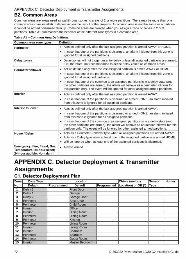
APPENDIX C. Detector Deployment & Transmitter Assignments
72 D-303222 PowerMaster-10/30 G2 Installer's Guide
B2. Common Areas Common areas are areas used as walkthrough zones to areas of 2 or more partitions. There may be more than one
common area in an installation depending on the layout of the property. A common area is not the same as a partition;
it cannot be armed / disarmed directly. Common areas are created when you assign a zone or zones to 2 or 3
partitions. Table A1 summarizes the behavior of the different zone types in a common area.
Table A1 – Common Area Definitions
Common area zone types Definition
Perimeter Acts as defined only after the last assigned partition is armed AWAY or HOME.
In case that one of the partitions is disarmed, an alarm initiated from this zone is ignored for all assigned partitions.
Delay zones Delay zones will not trigger an entry delay unless all assigned partitions are armed. It is, therefore, not recommended to define delay zones as common areas.
Perimeter follower Act as defined only after the last assigned partition is armed AWAY or HOME.
In case that one of the partitions is disarmed, an alarm initiated from this zone is ignored for all assigned partitions.
In case that one of the common area assigned partitions is in a delay state (and the other partitions are armed), the alarm will behave as a perimeter follower for this partition only. The event will be ignored for other assigned armed partitions.
Interior Acts as defined only after the last assigned partition is armed AWAY.
In case that one of the partitions is disarmed or armed HOME, an alarm initiated from this zone is ignored for all assigned partitions.
Interior follower Acts as defined only after the last assigned partition is armed AWAY.
In case that one of the partitions is disarmed or armed HOME, an alarm initiated from this zone is ignored for all assigned partitions.
In case that one of the common area assigned partitions is in a delay state (and the other partitions are armed), the alarm will behave as an interior follower for this partition only. The event will be ignored for other assigned armed partitions.
Home / Delay Acts as a Perimeter-Follower type when all assigned partitions are armed AWAY.
Acts as a Delay type when at least one of the assigned partitions is armed HOME.
Will be ignored when at least one of the assigned partitions is disarmed.
Emergency; Fire; Flood; Gas;
Temperature; 24-hour silent; 24-hour audible; Non-alarm
Always armed.
APPENDIX C. Detector Deployment & Transmitter Assignments C1. Detector Deployment Plan Zone Zone Type Location Chime (melody Sensor Holder
No. Default Programmed Default Programmed Location) or Off (*) Type
1 Delay 1 Front Door
2 Delay 1 Garage
3 Delay 2 Garage Door
4 Perimeter Back Door
5 Perimeter Child Room
6 Interior Office
7 Interior Dining Room
8 Perimeter Dining Room
9 Perimeter Kitchen
10 Perimeter Living Room
11 Interior Living Room
12 Interior Bedroom
13 Perimeter Bedroom
14 Perimeter Guest Room
15 Interior Master Bedroom
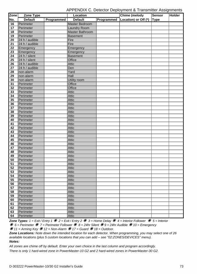
APPENDIX C. Detector Deployment & Transmitter Assignments
D-303222 PowerMaster-10/30 G2 Installer's Guide 73
Zone Zone Type Location Chime (melody Sensor Holder
No. Default Programmed Default Programmed Location) or Off (*) Type
16 Perimeter Master Bedroom
17 Perimeter Laundry Room
18 Perimeter Master Bathroom
19 Perimeter Basement
20 24 h / audible Fire
21 24 h / audible Fire
22 Emergency Emergency
23 Emergency Emergency
24 24 h / silent Basement
25 24 h / silent Office
26 24 h / audible Attic
27 24 h / audible Den
28 non-alarm Yard
29 non-alarm Hall
30 non-alarm Utility room
31 Perimeter Office
32 Perimeter Office
33 Perimeter Attic
34 Perimeter Attic
35 Perimeter Attic
36 Perimeter Attic
37 Perimeter Attic
38 Perimeter Attic
39 Perimeter Attic
40 Perimeter Attic
41 Perimeter Attic
42 Perimeter Attic
43 Perimeter Attic
44 Perimeter Attic
45 Perimeter Attic
46 Perimeter Attic
47 Perimeter Attic
48 Perimeter Attic
49 Perimeter Attic
50 Perimeter Attic
51 Perimeter Attic
52 Perimeter Attic
53 Perimeter Attic
54 Perimeter Attic
55 Perimeter Attic
56 Perimeter Attic
57 Perimeter Attic
58 Perimeter Attic
59 Perimeter Attic
60 Perimeter Attic
61 Perimeter Attic
62 Perimeter Attic
63 Perimeter Attic
64 Perimeter Attic
Zone Types: 1 = Exit / Entry 1 2 = Exit / Entry 2 3 = Home Delay 4 = Interior Follower 5 = Interior
6 = Perimeter 7 = Perimeter Follower 8 = 24hr Silent 9 = 24hr Audible 10 = Emergency 11 = Arming Key 12 = Non-Alarm 17 = Guard 18 = Outdoor.
Zone Locations: Note down the intended location for each detector. When programming, you may select one of 26
available locations (plus 5 custom locations that you can add – see "02:ZONES/DEVICES" menu).
Notes:
All zones are chime off by default. Enter your own choice in the last column and program accordingly.
There is only 1 hard-wired zone in PowerMaster-10 G2 and 2 hard-wired zones in PowerMaster-30 G2.
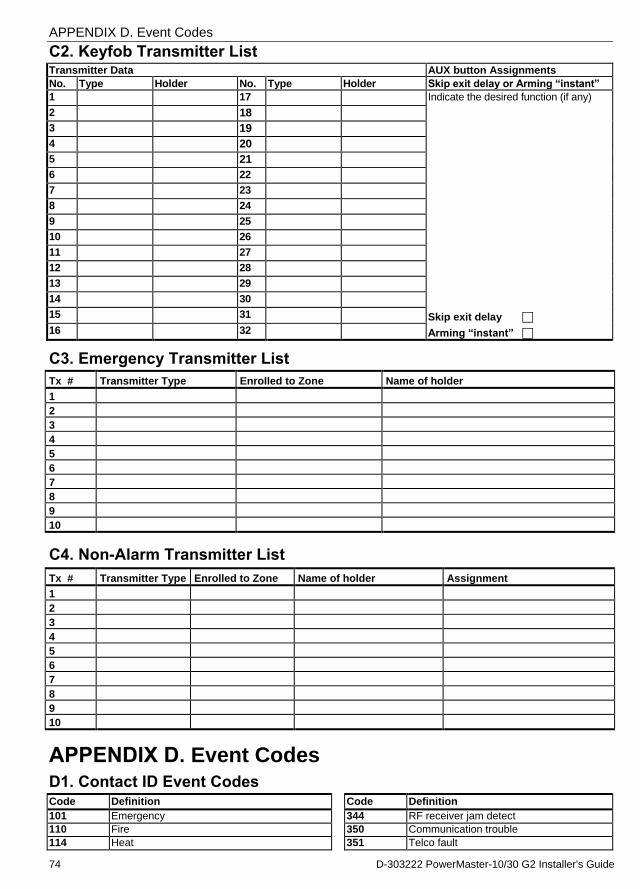
APPENDIX D. Event Codes
74 D-303222 PowerMaster-10/30 G2 Installer's Guide
C2. Keyfob Transmitter List Transmitter Data AUX button Assignments
No. Type Holder No. Type Holder Skip exit delay or Arming “instant”
1 17 Indicate the desired function (if any)
2 18
3 19
4 20
5 21
6 22
7 23
8 24
9 25
10 26
11 27
12 28
13 29
14 30
15 31 Skip exit delay
16 32 Arming “instant”
C3. Emergency Transmitter List
Tx # Transmitter Type Enrolled to Zone Name of holder
1
2
3
4
5
6
7
8
9
10
C4. Non-Alarm Transmitter List
Tx # Transmitter Type Enrolled to Zone Name of holder Assignment
1
2
3
4
5
6
7
8
9
10
APPENDIX D. Event Codes D1. Contact ID Event Codes Code Definition Code Definition
101 Emergency 344 RF receiver jam detect
110 Fire 350 Communication trouble
114 Heat 351 Telco fault
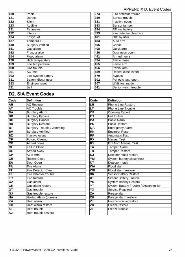
APPENDIX D. Event Codes
D-303222 PowerMaster-10/30 G2 Installer's Guide 75
120 Panic 373 Fire detector trouble
121 Duress 380 Sensor trouble
122 Silent 381 Inactive event
123 Audible 383 Sensor tamper
131 Perimeter 384 RF low battery
132 Interior 393 Fire detector clean me
134 Entry/Exit 401 O/C by user
137 Tamper/CP 403 Auto arm
139 Burglary verified 406 Cancel
151 Gas alarm 408 Quick arm
152 Freezer alert 426 Door open event
154 Flood alarm 441 Armed home
158 High temperature 454 Fail to close
159 Low temperature 455 Fail to arm
180 Gas trouble 456 Partial arm
301 AC loss 459 Recent close event
302 Low system battery 570 Bypass
311 Battery disconnect 602 Periodic test report
313 Engineer reset 607 Walk test mode
321 Bell 641 Senior watch trouble
D2. SIA Event Codes
Code Definition Code Definition
AR AC Restore LR Phone Line Restore
AT AC Trouble LT Phone Line Trouble
BA Burglary Alarm OP Opening Report
BB Burglary Bypass OT Fail to Arm
BC Burglary Cancel PA Panic Alarm
BR Burglary Restore PR Panic Restore
BT Burglary Trouble / Jamming QA Emergency Alarm
BV Burglary Verified RN Engineer Reset
BZ Inactive event RP Automatic Test
CF Forced Closing RX Manual Test
CG Armed home RY Exit from Manual Test
CI Fail to Close TA Tamper Alarm
CL Armed Away TR Tamper Restore
CP Auto Arm UJ Detector mask restore
CR Recent Close YM System battery disconnect
EA Door Open UT Detector mask
FA Fire Alarm WA Flood alarm
FT Fire Detector Clean WR Flood alarm restore
FJ Fire detector trouble XR Sensor Battery Restore
FR Fire Restore XT Sensor Battery Trouble
GA Gas alarm YR System Battery Restore
GR Gas alarm restore YT System Battery Trouble / Disconnection
GT Gas trouble YX Service Required
GJ Gas trouble restore ZA Freeze alarm
HA Holdup Alarm (duress) ZH Freeze alarm restore
KA Heat alarm ZJ Freeze trouble restore
KH Heat alarm restore ZR Freeze restore
KT Heat trouble ZT Freeze trouble
KJ Heat trouble restore
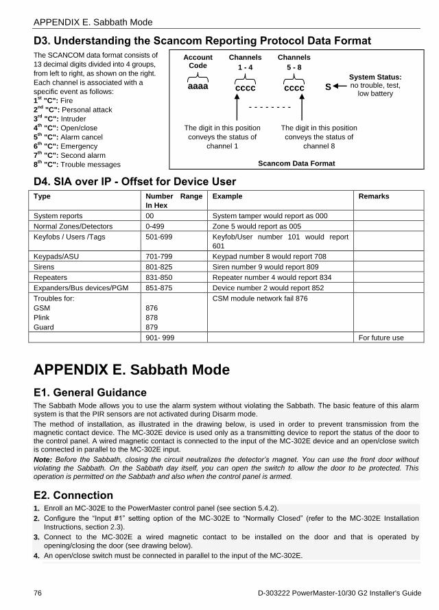
APPENDIX E. Sabbath Mode
76 D-303222 PowerMaster-10/30 G2 Installer's Guide
D3. Understanding the Scancom Reporting Protocol Data Format
The SCANCOM data format consists of
13 decimal digits divided into 4 groups,
from left to right, as shown on the right.
Each channel is associated with a
specific event as follows:
1st
"C": Fire
2nd
"C": Personal attack
3rd
"C": Intruder
4th
"C": Open/close
5th
"C": Alarm cancel
6th
"C": Emergency
7th
"C": Second alarm
8th
"C": Trouble messages
Account Code
aaaa
Channels
1 - 4
cccc
Channels
5 - 8
cccc
S System Status: no trouble, test,
low battery
- - - - - - - -
The digit in this position
conveys the status of
channel 1
The digit in this position
conveys the status of
channel 8
Scancom Data Format
D4. SIA over IP - Offset for Device User
Type Number Range
In Hex
Example Remarks
System reports 00 System tamper would report as 000
Normal Zones/Detectors 0-499 Zone 5 would report as 005
Keyfobs / Users /Tags 501-699 Keyfob/User number 101 would report
601
Keypads/ASU 701-799 Keypad number 8 would report 708
Sirens 801-825 Siren number 9 would report 809
Repeaters 831-850 Repeater number 4 would report 834
Expanders/Bus devices/PGM 851-875 Device number 2 would report 852
Troubles for:
GSM
Plink
Guard
876
878
879
CSM module network fail 876
901- 999 For future use
APPENDIX E. Sabbath Mode
E1. General Guidance The Sabbath Mode allows you to use the alarm system without violating the Sabbath. The basic feature of this alarm system is that the PIR sensors are not activated during Disarm mode.
The method of installation, as illustrated in the drawing below, is used in order to prevent transmission from the magnetic contact device. The MC-302E device is used only as a transmitting device to report the status of the door to the control panel. A wired magnetic contact is connected to the input of the MC-302E device and an open/close switch is connected in parallel to the MC-302E input.
Note: Before the Sabbath, closing the circuit neutralizes the detector’s magnet. You can use the front door without
violating the Sabbath. On the Sabbath day itself, you can open the switch to allow the door to be protected. This operation is permitted on the Sabbath and also when the control panel is armed.
E2. Connection 1. Enroll an MC-302E to the PowerMaster control panel (see section 5.4.2).
2. Configure the “Input #1” setting option of the MC-302E to “Normally Closed” (refer to the MC-302E Installation
Instructions, section 2.3).
3. Connect to the MC-302E a wired magnetic contact to be installed on the door and that is operated by
opening/closing the door (see drawing below).
4. An open/close switch must be connected in parallel to the input of the MC-302E.
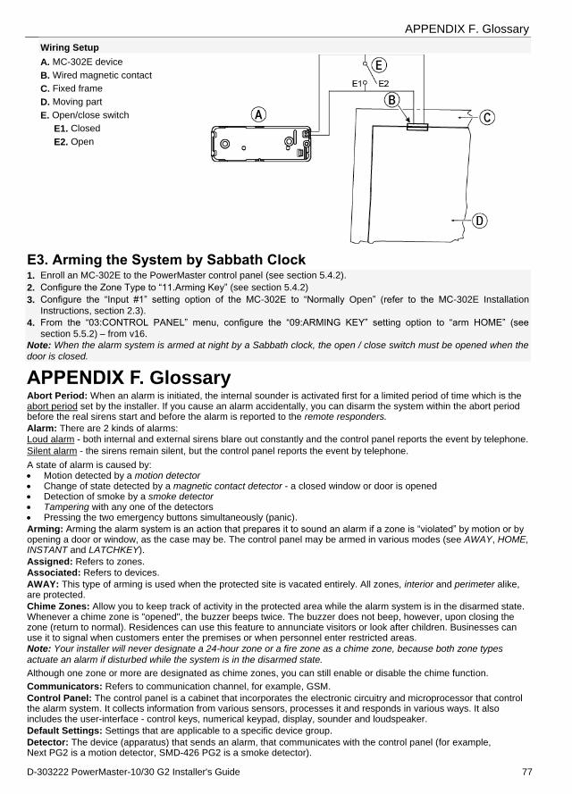
APPENDIX F. Glossary
D-303222 PowerMaster-10/30 G2 Installer's Guide 77
Wiring Setup
A. MC-302E device
B. Wired magnetic contact
C. Fixed frame
D. Moving part
E. Open/close switch
E1. Closed
E2. Open
E3. Arming the System by Sabbath Clock 1. Enroll an MC-302E to the PowerMaster control panel (see section 5.4.2).
2. Configure the Zone Type to “11.Arming Key” (see section 5.4.2)
3. Configure the “Input #1” setting option of the MC-302E to “Normally Open” (refer to the MC-302E Installation
Instructions, section 2.3).
4. From the “03:CONTROL PANEL” menu, configure the “09:ARMING KEY” setting option to “arm HOME” (see
section 5.5.2) – from v16.
Note: When the alarm system is armed at night by a Sabbath clock, the open / close switch must be opened when the
door is closed.
APPENDIX F. Glossary Abort Period: When an alarm is initiated, the internal sounder is activated first for a limited period of time which is the abort period set by the installer. If you cause an alarm accidentally, you can disarm the system within the abort period before the real sirens start and before the alarm is reported to the remote responders.
Alarm: There are 2 kinds of alarms: Loud alarm - both internal and external sirens blare out constantly and the control panel reports the event by telephone.
Silent alarm - the sirens remain silent, but the control panel reports the event by telephone.
A state of alarm is caused by: Motion detected by a motion detector Change of state detected by a magnetic contact detector - a closed window or door is opened Detection of smoke by a smoke detector Tampering with any one of the detectors Pressing the two emergency buttons simultaneously (panic).
Arming: Arming the alarm system is an action that prepares it to sound an alarm if a zone is “violated” by motion or by opening a door or window, as the case may be. The control panel may be armed in various modes (see AWAY, HOME, INSTANT and LATCHKEY).
Assigned: Refers to zones. Associated: Refers to devices.
AWAY: This type of arming is used when the protected site is vacated entirely. All zones, interior and perimeter alike, are protected.
Chime Zones: Allow you to keep track of activity in the protected area while the alarm system is in the disarmed state. Whenever a chime zone is "opened", the buzzer beeps twice. The buzzer does not beep, however, upon closing the zone (return to normal). Residences can use this feature to annunciate visitors or look after children. Businesses can use it to signal when customers enter the premises or when personnel enter restricted areas. Note: Your installer will never designate a 24-hour zone or a fire zone as a chime zone, because both zone types actuate an alarm if disturbed while the system is in the disarmed state.
Although one zone or more are designated as chime zones, you can still enable or disable the chime function.
Communicators: Refers to communication channel, for example, GSM.
Control Panel: The control panel is a cabinet that incorporates the electronic circuitry and microprocessor that control the alarm system. It collects information from various sensors, processes it and responds in various ways. It also includes the user-interface - control keys, numerical keypad, display, sounder and loudspeaker.
Default Settings: Settings that are applicable to a specific device group.
Detector: The device (apparatus) that sends an alarm, that communicates with the control panel (for example, Next PG2 is a motion detector, SMD-426 PG2 is a smoke detector).

APPENDIX F. Glossary
78 D-303222 PowerMaster-10/30 G2 Installer's Guide
Disarming: The opposite of arming - an action that restores the control panel to the normal standby state. In this state, only fire and 24-hour zones will sound an alarm if violated, but a “panic alarm” may also be initiated.
Disturbed Zone: A zone in a state of alarm (this may be caused by an open window or door or by motion in the field of view of a motion detector). A disturbed zone is considered “not secured”.
Forced Arming: When any one of the system zones is disturbed (open), the alarm system cannot be armed. One way to solve this problem is to find and eliminate the cause for zone disturbance (closing doors and windows). Another way to deal with this is to impose forced arming - automatic de-activation of zones that are still disturbed upon termination of the exit delay. Bypassed zones will not be protected throughout the arming period. Even if restored to normal (closed), bypassed zones will remain unprotected until the system is disarmed. Permission to “force arm” is given or denied by the installer while programming the system.
HOME: This type of arming is used when people are present within the protected site. A classic example is night-time at home, when the family is about to retire to bed. With HOME arming, perimeter zones are protected but interior zones are not. Consequently, motion within interior zones will be ignored by the control panel, but disturbance of a perimeter zone will cause an alarm.
Instant: You can arm the system AWAY-INSTANT or HOME-INSTANT, thereby canceling the entry delay for all delay zones for the duration of one arming period. For example, you may arm the control panel in the HOME-INSTANT mode and remain within the protected area. Only perimeter protection is active, and if you do not expect somebody to drop in while the system is armed, alarm upon entry via the main door is an advantage. To disarm the system without causing an alarm, use your control keypad (which is normally accessible without disturbing a perimeter zone) or use a keyfob transmitter.
Latchkey: The Latchkey mode is a special arming mode in which designated "latchkey users" will trigger a "latchkey message" to be sent to a telephone when they disarm the system.
For example, if a parent wants to be sure that their child has returned from school and disarmed the system. Latchkey arming is only possible when the system is armed in the AWAY mode.
Location: Assigning a named location to a device (for example, Garage, Front Door etc.)
Magnetic Contact Detector, Wireless: A Magnet- controlled switch and a wireless PowerG transmitter in a shared housing. The detector is mounted on doors and windows to detect changes in state (from closed to open and vice versa). Upon sensing that a door or window is open, the detector transmits its unique identification code accompanied by an “alarm” signal and various other status signals to the control panel. The control panel, if not armed at that time, will consider the alarm system as “not ready for arming” until it receives a “restored” signal from the same detector. Motion Detector, Wireless: A passive Infrared motion sensor and a wireless PowerG transmitter in a shared housing. Upon sensing motion, the detector transmits its unique identification code, accompanied by an alarm signal and various other status signals to the control panel. After transmission, it stands by to sense further motion.
Non-Alarm Zone: Your installer can designate a zone for roles other than alarm. For instance, a motion detector installed in a dark stairway may be used to switch on lights automatically when someone crosses the dark area. Another example is a wireless transmitter linked to a zone that controls a gate opening mechanism.
Quick Arming: Arming without a user code. The control panel does not request your user code when you press one of the arming buttons. Permission to use this arming method is given or denied by the installer while programming the system.
Remote Responder: A responder can be either a professional service provider to which the home or business owner subscribes (a Monitoring Station) or a family relation/friend who agrees to look after the protected site during absence of its occupants. The control panel reports events by telephone to both kinds of responders.
Restore: When a detector reverts from the state of alarm to the normal standby state, it is said to have been “restored”. A motion detector restores automatically after detection of movement, and becomes ready to detect again. This kind of “restore” is not reported to the remote responders. A magnetic contact detector restores only upon closure of the protected door or window. This kind of “restore” is reported to the remote responders.
Sensor: The sensing element: pyroelectric sensor, photo-diode, microphone, smoke optical sensor etc.
Signal Strength: The quality link communication between the system components and the control panel.
Smoke Detector, Wireless: A regular smoke detector and a wireless PowerG transmitter in a shared housing. Upon detection of smoke, the detector transmits its unique identification code accompanied by an alarm signal and various status signals to the control panel. Since the smoke detector is linked to a special fire zone, a fire alarm is initiated. State: AWAY, HOME, AWAY-INSTANT, HOME-INSTANT, LATCHKEY, FORCED, BYPASS. Status: AC fail, low battery, trouble, etc.
User Codes: The PowerMaster is designed to obey your commands, provided that they are preceded by a valid security access code. Unauthorized people do not know this code, so any attempt on their part to disarm or defeat the system is bound to fail. Some operations, however, can be carried out without a user code as they do not degrade the security level of the alarm system. Zone: A zone is an area within the protected site under supervision of a specific detector. During programming, the installer allows the control panel to learn the detector’s identity code and links it to the desired zone. Since the zone is distinguished by number and name, the control panel can report the zone status to the user and register in its memory all the events reported by the zone detector. Instant and delay zones are “on watch” only when the control panel is armed, and other (24-hour) zones are “on watch” regardless of whether the system is armed or not. Zone Type: The zone type determines how the system handles alarms and other signals sent from the device.
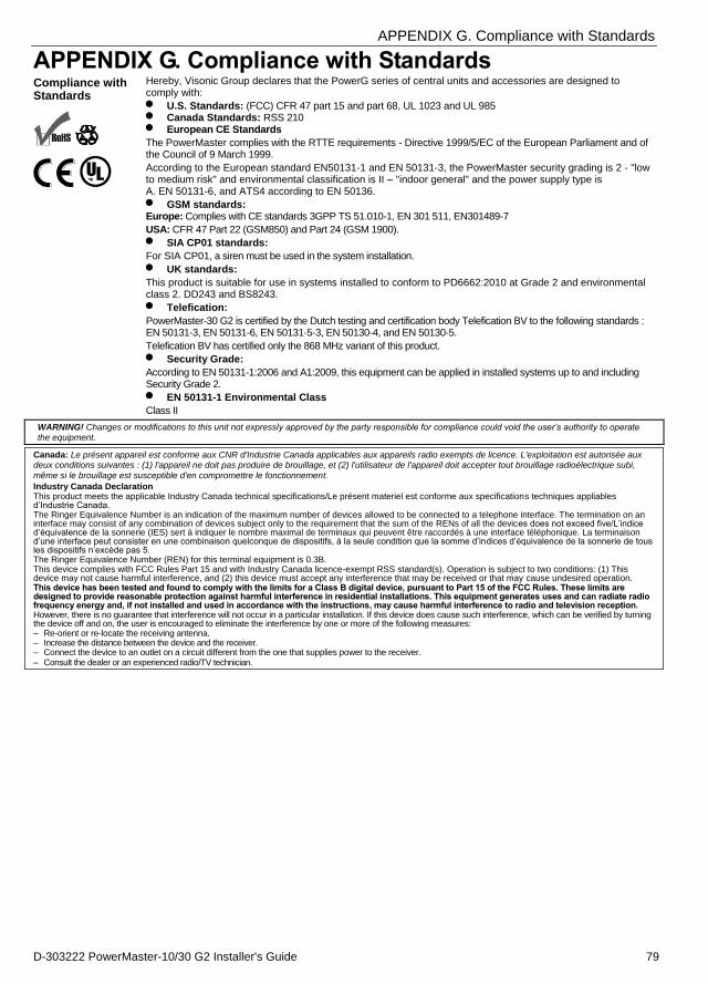
APPENDIX G. Compliance with Standards
D-303222 PowerMaster-10/30 G2 Installer's Guide 79
APPENDIX G. Compliance with Standards Compliance with Standards
R
Hereby, Visonic Group declares that the PowerG series of central units and accessories are designed to comply with:
U.S. Standards: (FCC) CFR 47 part 15 and part 68, UL 1023 and UL 985 Canada Standards: RSS 210 European CE Standards
The PowerMaster complies with the RTTE requirements - Directive 1999/5/EC of the European Parliament and of the Council of 9 March 1999.
According to the European standard EN50131-1 and EN 50131-3, the PowerMaster security grading is 2 - "low to medium risk" and environmental classification is II – "indoor general" and the power supply type is A. EN 50131-6, and ATS4 according to EN 50136.
GSM standards: Europe: Complies with CE standards 3GPP TS 51.010-1, EN 301 511, EN301489-7
USA: CFR 47 Part 22 (GSM850) and Part 24 (GSM 1900).
SIA CP01 standards:
For SIA CP01, a siren must be used in the system installation.
UK standards:
This product is suitable for use in systems installed to conform to PD6662:2010 at Grade 2 and environmental class 2. DD243 and BS8243.
Telefication:
PowerMaster-30 G2 is certified by the Dutch testing and certification body Telefication BV to the following standards : EN 50131-3, EN 50131-6, EN 50131-5-3, EN 50130-4, and EN 50130-5.
Telefication BV has certified only the 868 MHz variant of this product.
Security Grade:
According to EN 50131-1:2006 and A1:2009, this equipment can be applied in installed systems up to and including Security Grade 2.
EN 50131-1 Environmental Class
Class II WARNING! Changes or modifications to this unit not expressly approved by the party responsible for compliance could void the user’s authority to operate the equipment.
Canada: Le présent appareil est conforme aux CNR d'Industrie Canada applicables aux appareils radio exempts de licence. L'exploitation est autorisée aux deux conditions suivantes : (1) l'appareil ne doit pas produire de brouillage, et (2) l'utilisateur de l'appareil doit accepter tout brouillage radioélectrique subi,
même si le brouillage est susceptible d'en compromettre le fonctionnement.
Industry Canada Declaration This product meets the applicable Industry Canada technical specifications/Le présent materiel est conforme aux specifications techniques appliables d’Industrie Canada. The Ringer Equivalence Number is an indication of the maximum number of devices allowed to be connected to a telephone interface. The termination on an interface may consist of any combination of devices subject only to the requirement that the sum of the RENs of all the devices does not exceed five/L’indice d’équivalence de la sonnerie (IES) sert à indiquer le nombre maximal de terminaux qui peuvent être raccordés à une interface téléphonique. La terminaison d’une interface peut consister en une combinaison quelconque de dispositifs, à la seule condition que la somme d’indices d’équivalence de la sonnerie de tous les dispositifs n’excède pas 5. The Ringer Equivalence Number (REN) for this terminal equipment is 0.3B. This device complies with FCC Rules Part 15 and with Industry Canada licence-exempt RSS standard(s). Operation is subject to two conditions: (1) This device may not cause harmful interference, and (2) this device must accept any interference that may be received or that may cause undesired operation. This device has been tested and found to comply with the limits for a Class B digital device, pursuant to Part 15 of the FCC Rules. These limits are designed to provide reasonable protection against harmful interference in residential installations. This equipment generates uses and can radiate radio frequency energy and, if not installed and used in accordance with the instructions, may cause harmful interference to radio and television reception. However, there is no guarantee that interference will not occur in a particular installation. If this device does cause such interference, which can be verified by turning the device off and on, the user is encouraged to eliminate the interference by one or more of the following measures: – Re-orient or re-locate the receiving antenna. – Increase the distance between the device and the receiver. – Connect the device to an outlet on a circuit different from the one that supplies power to the receiver. – Consult the dealer or an experienced radio/TV technician.
APPENDIX G. Compliance with Standards
80 D-303222 PowerMaster-10/30 G2 Installer's Guide
WARRANTY Visonic Limited (the “Manufacturer") warrants this product only (the "Product") to the original
purchaser only (the “Purchaser”) against defective workmanship and materials under normal
use of the Product for a period of twelve (12) months from the date of shipment by the
Manufacturer.
This Warranty is absolutely conditional upon the Product having been properly installed,
maintained and operated under conditions of normal use in accordance with the
Manufacturers recommended installation and operation instructions. Products which have
become defective for any other reason, according to the Manufacturers discretion, such as
improper installation, failure to follow recommended installation and operational instructions,
neglect, willful damage, misuse or vandalism, accidental damage, alteration or tampering, or
repair by anyone other than the manufacturer, are not covered by this Warranty.
The Manufacturer does not represent that this Product may not be compromised and/or
circumvented or that the Product will prevent any death and/or personal injury and/or damage
to property resulting from burglary, robbery, fire or otherwise, or that the Product will in all
cases provide adequate warning or protection. The Product, properly installed and
maintained, only reduces the risk of such events without warning and it is not a guarantee or
insurance that such events will not occur.
THIS WARRANTY IS EXCLUSIVE AND EXPRESSLY IN LIEU OF ALL OTHER
WARRANTIES, OBLIGATIONS OR LIABILITIES, WHETHER WRITTEN, ORAL, EXPRESS
OR IMPLIED, INCLUDING ANY WARRANTY OF MERCHANTABILITY OR FITNESS FOR
A PARTICULAR PURPOSE, OR OTHERWISE. IN NO CASE SHALL THE
MANUFACTURER BE LIABLE TO ANYONE FOR ANY CONSEQUENTIAL OR
INCIDENTAL DAMAGES FOR BREACH OF THIS WARRANTY OR ANY OTHER
WARRANTIES WHATSOEVER, AS AFORESAID.
THE MANUFACTURER SHALL IN NO EVENT BE LIABLE FOR ANY SPECIAL,
INDIRECT, INCIDENTAL, CONSEQUENTIAL OR PUNITIVE DAMAGES OR FOR LOSS,
DAMAGE, OR EXPENSE, INCLUDING LOSS OF USE, PROFITS, REVENUE, OR
GOODWILL, DIRECTLY OR INDIRECTLY ARISING FROM PURCHASER’S USE OR
INABILITY TO USE THE PRODUCT, OR FOR LOSS OR DESTRUCTION OF OTHER
PROPERTY OR FROM ANY OTHER CAUSE, EVEN IF MANUFACTURER HAS BEEN
ADVISED OF THE POSSIBILITY OF SUCH DAMAGE.
THE MANUFACTURER SHALL HAVE NO LIABILITY FOR ANY DEATH, PERSONAL
AND/OR BODILY INJURY AND/OR DAMAGE TO PROPERTY OR OTHER LOSS
WHETHER DIRECT, INDIRECT, INCIDENTAL, CONSEQUENTIAL OR OTHERWISE,
BASED ON A CLAIM THAT THE PRODUCT FAILED TO FUNCTION.
However, if the Manufacturer is held liable, whether directly or indirectly, for any loss or
damage arising under this limited warranty, THE MANUFACTURER'S MAXIMUM LIABILITY
(IF ANY) SHALL NOT IN ANY CASE EXCEED THE PURCHASE PRICE OF THE
PRODUCT, which shall be fixed as liquidated damages and not as a penalty, and shall be the
complete and exclusive remedy against the Manufacturer.
When accepting the delivery of the Product, the Purchaser agrees to the said conditions of
sale and warranty and he recognizes having been informed of.
Some jurisdictions do not allow the exclusion or limitation of incidental or consequential
damages, so these limitations may not apply under certain circumstances.
The Manufacturer shall be under no liability whatsoever arising out of the corruption and/or
malfunctioning of any telecommunication or electronic equipment or any programs.
The Manufacturers obligations under this Warranty are limited solely to repair and/or replace
at the Manufacturer’s discretion any Product or part thereof that may prove defective. Any
repair and/or replacement shall not extend the original Warranty period. The Manufacturer
shall not be responsible for dismantling and/or reinstallation costs. To exercise this Warranty
the Product must be returned to the Manufacturer freight pre-paid and insured. All freight and
insurance costs are the responsibility of the Purchaser and are not included in this Warranty.
This warranty shall not be modified, varied or extended, and the Manufacturer does not
authorize any person to act on its behalf in the modification, variation or extension of this
warranty. This warranty shall apply to the Product only. All products, accessories or
attachments of others used in conjunction with the Product, including batteries, shall be
covered solely by their own warranty, if any. The Manufacturer shall not be liable for any
damage or loss whatsoever, whether directly, indirectly, incidentally, consequentially or
otherwise, caused by the malfunction of the Product due to products, accessories, or
attachments of others, including batteries, used in conjunction with the Products. This
Warranty is exclusive to the original Purchaser and is not assignable.
This Warranty is in addition to and does not affect your legal rights. Any provision in this
warranty which is contrary to the Law in the state or country were the Product is supplied
shall not apply.
Warning: The user must follow the Manufacturer’s installation and operational instructions
including testing the Product and its whole system at least once a week and to take all
necessary precautions for his/her safety and the protection of his/her property.
1/08
EMAIL: [email protected]
INTERNET: www.visonic.com VISONIC LTD. 2013 POWERMASTER-10/30 G2 Installer's Guide D-303222 Rev 3 (3/13)

© 2
013
Viso
nic
Ltd.
All
right
s re
serv
ed. P
ower
Mas
ter-
10 /
Pow
erM
aste
r-30
Eng
lish
Inst
alle
r Gui
de D
-303
222
www.visonic.com
Fully supervised wireless alarm control system
PowerMaster-30 G2INSTALLER GUIDE