cyclic redundancy codes
DESCRIPTION
Cyclic redundancy codes. Circuit elements in Digital computations Prof. Seok-Bum Ko Mehrnoosh Janbakhsh Jan29, 2010. Novel Table Lookup-Based Algorithms for High-Performance CRC Generation. - PowerPoint PPT PresentationTRANSCRIPT
Cyclic redundancy codes
Circuit elements in Digital computations
Prof. Seok-Bum Ko
Mehrnoosh Janbakhsh
Jan29, 2010
2
Novel Table Lookup-Based Algorithms for High-Performance
CRC Generation
VOL.57, NO.11, November 2008
Michael E. Kounavis, Member, IEEE
Frank L. Berry
3
Introduction
CRC are used for detecting the digital content corruption
CRC treats each bitstream as a binary polynomial All the binary words corresponing to remainder are
transmitted with the bitstream At the receiver side, CRC algorithms verify the
correct remainder has been received
4
Point of Interest
- New investigation on the CRC generation algorithms implementation in software
- Good for accelerating well known Codes
- Give more speed to many commercial host, network, and server chipsets
- A number of proposed Internet protocols like data center protocols require data integrity checks be performed above the transport layer by using very high speed CRCs(e.g., 10 Gbps)
5
Sarwate Algorithm
This algorithm is able to read 8 bits at a time from a stream and calculates the stream's CRC value by performing lookups on a table of 256 32-bit entries.
It was designed when most computer architectures allowed XOR operations between 8-bit quantities.
Now they can perform efficiently between 32- or 64-bit quantities and few clock cycles large on-chip cache memory access.
6
What is new here?
Novel slicing-by-4 algorithm
Based on Sarwate algorithm
Use a 4-Kbyte cache footprint
Double the existing CRC performance by reading 32 bits at a time
Novel slicing-by-8 algorithm
Based on Sarwate algorithm
Use a 8-Kbyte cache footprint
Triples the existing CRC performance by reading 64 bits at a time
7
Advantages
- Using the parallel lookup tables to generate the CRC values over long bitstreams.
- Compute the next remainder by performing parallel LUTs into smaller tables
8
Parallet LUTs concept
The concept of parallel table lookups appears in early CRC5 implementations and the work done by Braun and Waldvogel on performing incremental CRC updates for IP over ATM networks.
9
CRC Generation Process
CRCs are error detecting codes that are capable to detect the accidental alteration of data. Data in computer systems can be modified due to many reasons like hard drive malfunctions, Gaussian noise, and faulty physical connections.
10
How CRC algorithm works?
It treats each bitstream as a binary polynomial B(x) and the remainder R(x) from the division of B(x) with a standard ”generator” polynomial g(x).
The length of R(x) in bits is equal to the length of G(x) minus one.
At the reciever, CRC algorithms verify that R(x) is the correct remainder.
Additions and subtractions are carry-less so they are equal to the XOR logical operation.
11
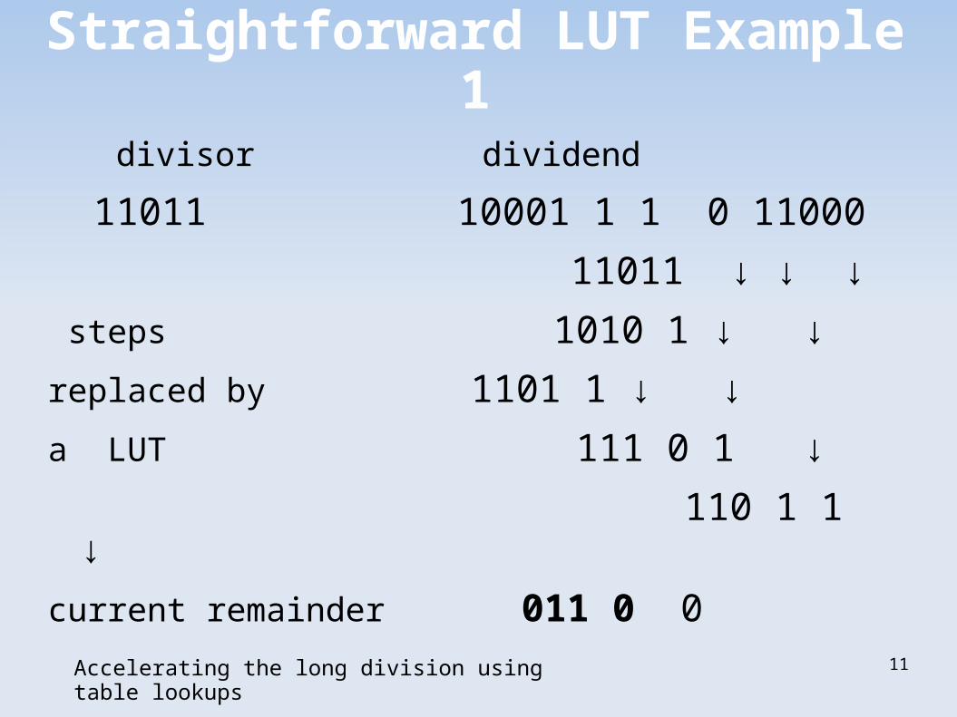
Straightforward LUT Example 1
divisor dividend
11011 10001 1 1 0 11000
11011 ↓ ↓ ↓
steps 1010 1 ↓ ↓
replaced by 1101 1 ↓ ↓
a LUT 111 0 1 ↓
110 1 1 ↓
current remainder 011 0 0
Accelerating the long division using table lookups
12
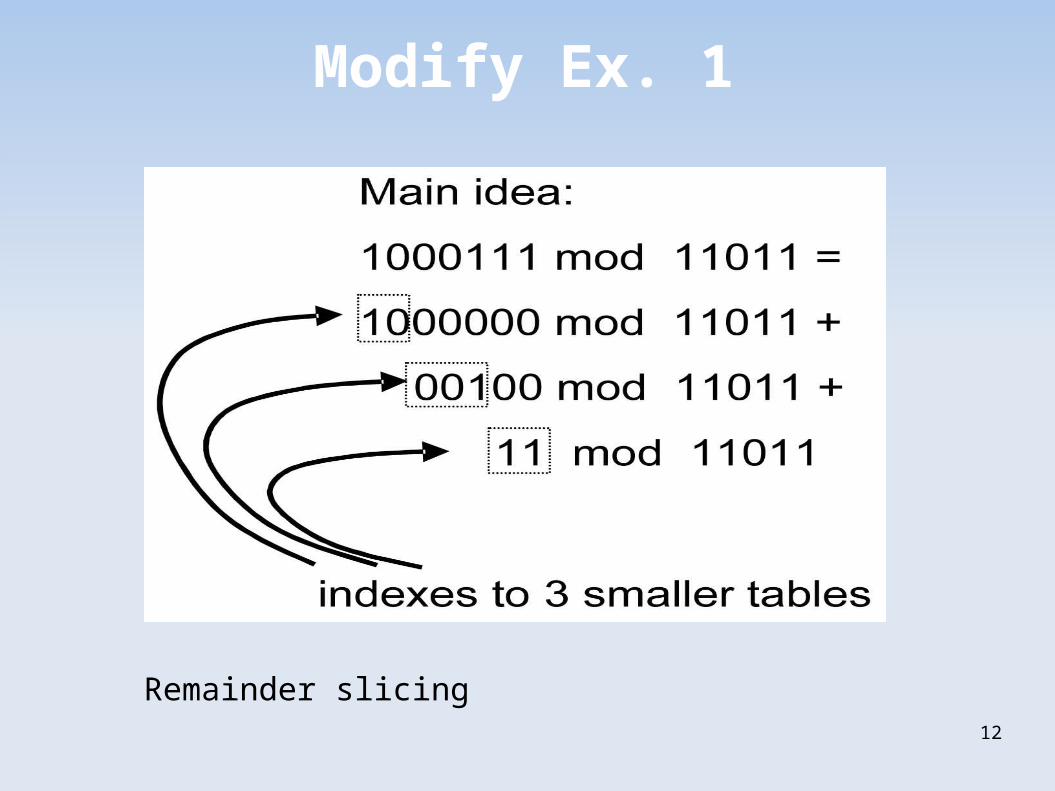
Modify Ex. 1
Remainder slicing
13
Sarwate Alg. disadvantage
The memory requirement is high when reading a large amount of bits at a time. For example, to achive acceleration by reading 32 bits at a time, table driven algorithm needs a table of 2 ³²= 4G entries.
14
First step
• p is the MSB of B (bit stream)
• l be the length of B, l>p
• g be the length of generator polynomial, g<l
• l-g+1 is B's MSB that got encoded
• g-1 is B's LSB that is equal to zero
15
Continue
• P= {b1,b2,.....bp} , B= {b1,b2,...,bl}
• P= {P1:P2:....:Pm}
• p is the length of P and p=Σpi
• P is sliced in order for our Alg. to be able to read potentially large amounts of data without having to access to LUT of 2 power p entries.
• Each Pi has its own LUT:Ti by the size of 2 power pi and contains the shifted remainders by an offset oi.
16
calculations
• oi = ∑pj , m< j < i+1
• Let's R1 (i) be the values from LUT during first step: Ri (1)= Pi . 2 power oi mod G
• Ri (1)= ө Ri (1) , m<i<1
• S(1)=[ R(1): Q(1)]=R(1).2 power q ө Q(1)
• Q(1) is the set of next q bits of the bit stream after p bits
Q(1)=[bp+1bp+2....bp+q]
17
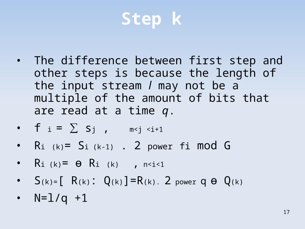
Step k
• The difference between first step and other steps is because the length of the input stream l may not be a multiple of the amount of bits that are read at a time q.
• f i = ∑ sj , m<j <i+1
• Ri (k)= Si (k-1) . 2 power fi mod G
• Ri (k)= ө Ri (k) , n<i<1
• S(k)=[ R(k): Q(k)]=R(k). 2 power q ө Q(k)
• N=l/q +1
18
Correctness
They prove the correctness of the algorithmic framework by showing the value of R(n) that is produced in the last step of framework is indeed the remainder from the division of the input stream B with the generator polynomial using modulo-2 arithmetic.
19
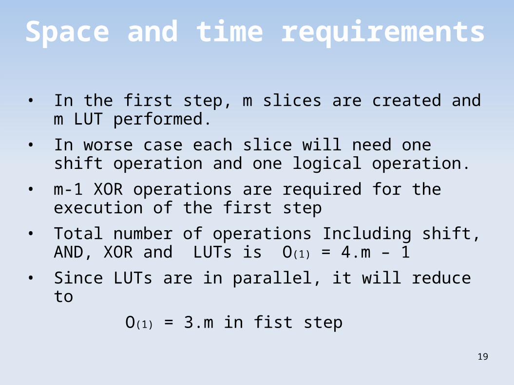
Space and time requirements
• In the first step, m slices are created and m LUT performed.
• In worse case each slice will need one shift operation and one logical operation.
• m-1 XOR operations are required for the execution of the first step
• Total number of operations Including shift, AND, XOR and LUTs is O(1) = 4.m – 1
• Since LUTs are in parallel, it will reduce to
O(1) = 3.m in fist step
20
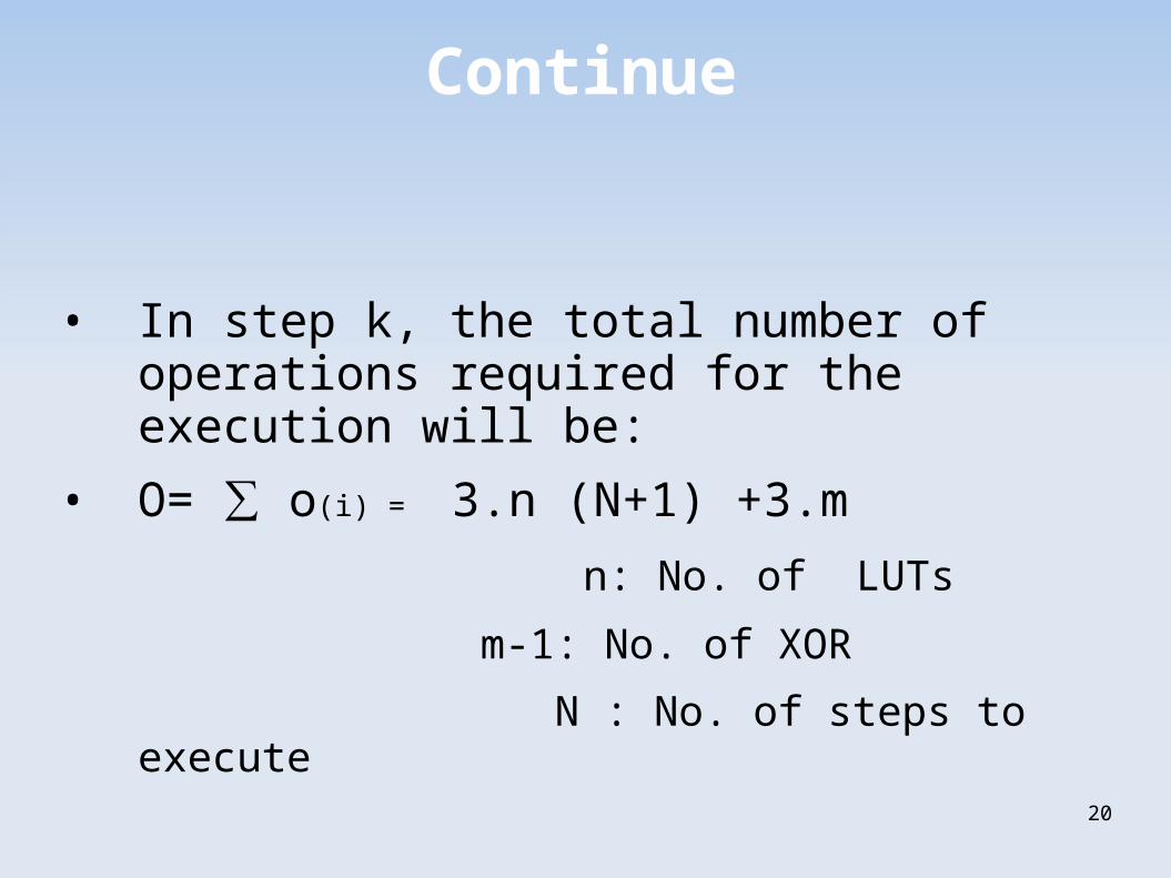
Continue
• In step k, the total number of operations required for the execution will be:
• O= ∑ o(i) = 3.n (N+1) +3.m
n: No. of LUTs
m-1: No. of XOR
N : No. of steps to execute
21
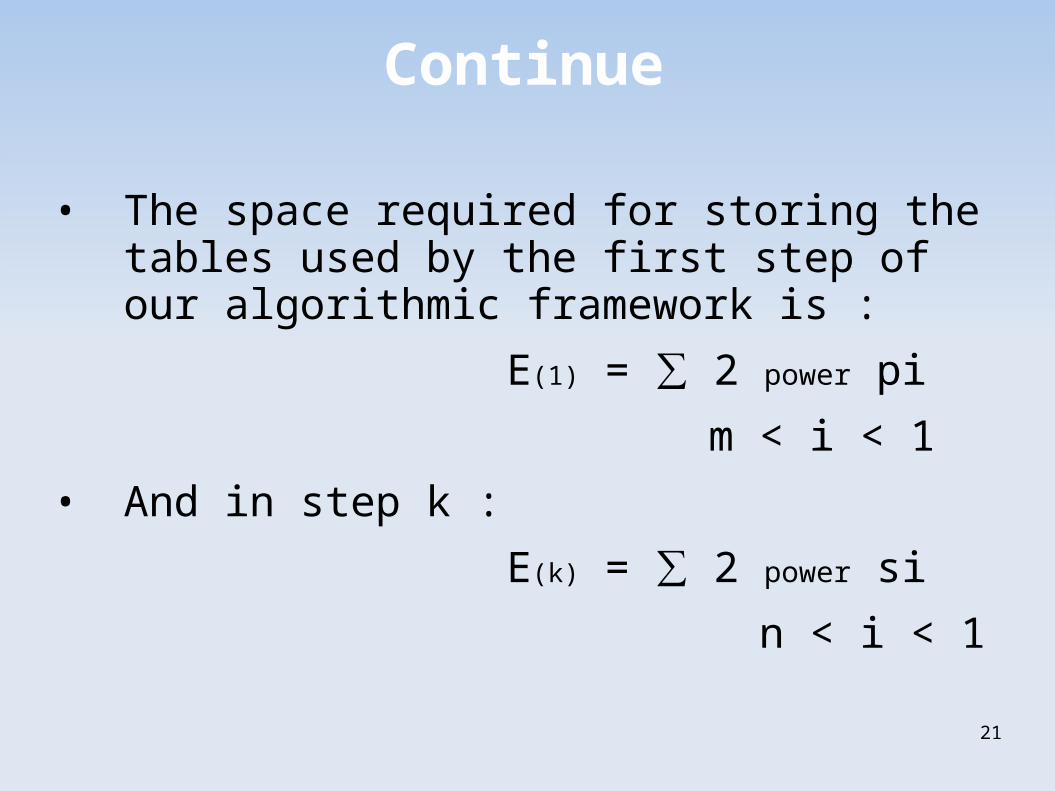
Continue
• The space required for storing the tables used by the first step of our algorithmic framework is :
E(1) = ∑ 2 power pi
m < i < 1
• And in step k :
E(k) = ∑ 2 power si
n < i < 1
22
Riminder
• The total space requirement of the slicing by 4 Alg. is 4 K bytes and it could read 32 bits at a time.
• The total space requirement of the slicing by 8 Alg. is 8 K bytes and it could read 64 bits at a time.
23
Evaluation
• It is a trade-off between the number of logical operations and the space requirement of the algorithm.
• If tables are stored in an external memory unit, the latency associated with accessing these tables may be significantly higher than they are stored in a cache unit.
• Slicing reduces the number of operations performed for each byte of an input stream.
24
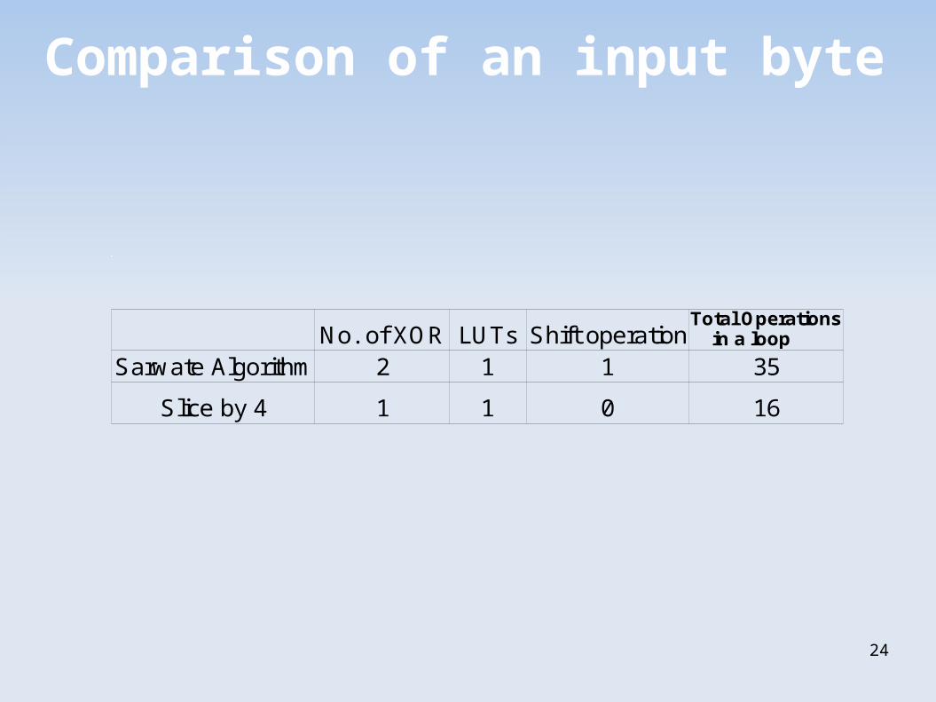
Comparison of an input byte
No. of XOR Shift operation2 1 1 35
Slice by 4 1 1 0 16
LUTsTotal Operations in a loop
Sarwate Algorithm
25
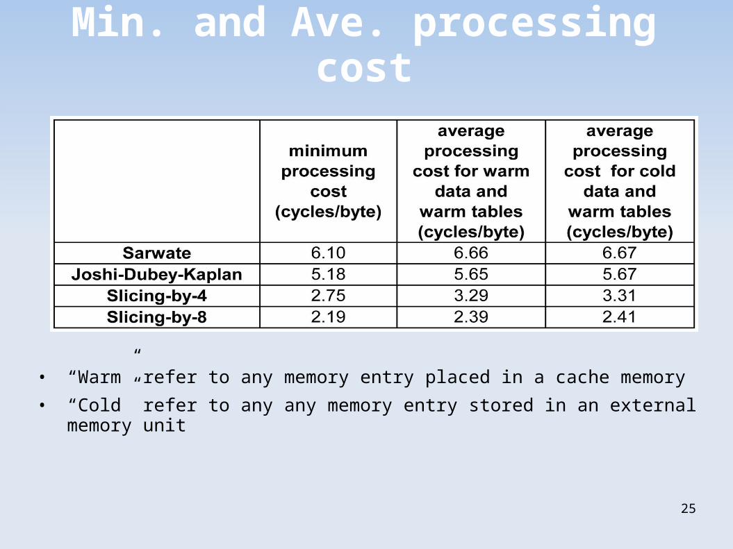
Min. and Ave. processing cost
• “Warm” refer to any memory entry placed in a cache memory
• “Cold” refer to any any memory entry stored in an external memory unit

26
Any Questions?