cur so aspen
TRANSCRIPT
©2000 AspenTech. All Rights Reserved.
Introduction to Flowsheet Simulation
Objective:Introduce general flowsheet simulation concepts
and Aspen Plus features
©2000 AspenTech. All Rights Reserved. Introduction to Aspen Plus
Flowsheet Simulation
• What is flowsheet simulation?
Use of a computer program to quantitatively model the characteristic equations of a chemical process
• Uses underlying physical relationships– Mass and energy balance– Equilibrium relationships– Rate correlations (reaction and mass/heat transfer)
• Predicts– Stream flowrates, compositions, and properties– Operating conditions– Equipment sizes
©2000 AspenTech. All Rights Reserved. Introduction to Aspen Plus
Advantages of Simulation
• Reduces plant design time– Allows designer to quickly test various plant configurations
• Helps improve current process– Answers “what if” questions– Determines optimal process conditions within given constraints– Assists in locating the constraining parts of a process
(debottlenecking)
©2000 AspenTech. All Rights Reserved. Introduction to Aspen Plus
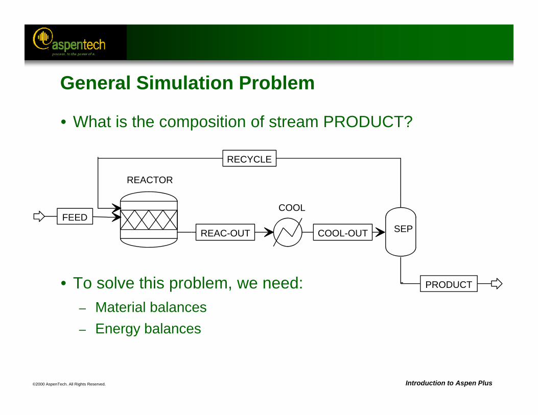
• What is the composition of stream PRODUCT?
• To solve this problem, we need:– Material balances– Energy balances
REACTOR
FEED
RECYCLE
REAC-OUT
COOL
COOL-OUT SEP
PRODUCT
General Simulation Problem
©2000 AspenTech. All Rights Reserved. Introduction to Aspen Plus
Approaches to Flowsheet Simulation
• Sequential Modular– Aspen Plus is a sequential modular simulation program.– Each unit operation block is solved in a certain sequence.
• Equation Oriented– Aspen Custom Modeler (formerly SPEEDUP) is an equation oriented
simulation program.– All equations are solved simultaneously.
• Combination– Aspen Dynamics (formerly DynaPLUS) uses the Aspen Plus
sequential modular approach to initialize the steady state simulation and the Aspen Custom Modeler (formerly SPEEDUP) equation oriented approach to solve the dynamic simulation.
©2000 AspenTech. All Rights Reserved. Introduction to Aspen Plus
Good Flowsheeting Practice
• Build large flowsheets a few blocks at a time.– This facilitates troubleshooting if errors occur.
• Ensure flowsheet inputs are reasonable.
• Check that results are consistent and realistic.
©2000 AspenTech. All Rights Reserved. Introduction to Aspen Plus
Important Features of Aspen Plus
• Rigorous Electrolyte Simulation
• Solids Handling
• Petroleum Handling
• Data Regression
• Data Fit
• Optimization
• User Routines
©2000 AspenTech. All Rights Reserved.
Aspen Plus References:User Guide, Chapter 1, The User InterfaceUser Guide, Chapter 2, Creating a Simulation ModelUser Guide, Chapter 4, Defining the Flowsheet
The User Interface
Objective:Become comfortable and familiar with the Aspen
Plus graphical user interface

©2000 AspenTech. All Rights Reserved. Introduction to Aspen Plus
Run ID
Tool Bar
Title Bar
Menu Bar
Select Modebutton Model
Library
Model MenuTabs Process
FlowsheetWindow
Next Button
Status Area
The User Interface
Reference: Aspen Plus User Guide, Chapter 1, The User Interface
©2000 AspenTech. All Rights Reserved. Introduction to Aspen Plus
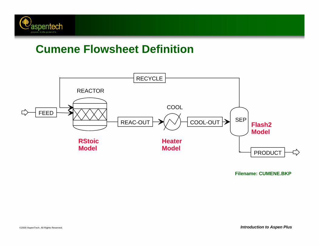
RStoicModel
HeaterModel
Flash2Model
Filename: CUMENE.BKP
REACTOR
FEED
RECYCLE
REAC-OUT
COOL
COOL-OUT SEP
PRODUCT
Cumene Flowsheet Definition
©2000 AspenTech. All Rights Reserved. Introduction to Aspen Plus
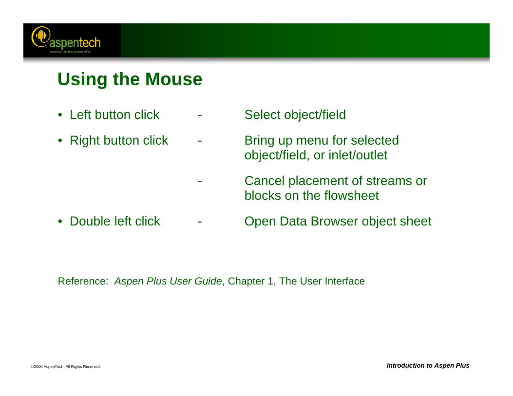
Using the Mouse
• Left button click - Select object/field
• Right button click - Bring up menu for selected object/field, or inlet/outlet
- Cancel placement of streams or blocks on the flowsheet
• Double left click - Open Data Browser object sheet
Reference: Aspen Plus User Guide, Chapter 1, The User Interface
©2000 AspenTech. All Rights Reserved. Introduction to Aspen Plus
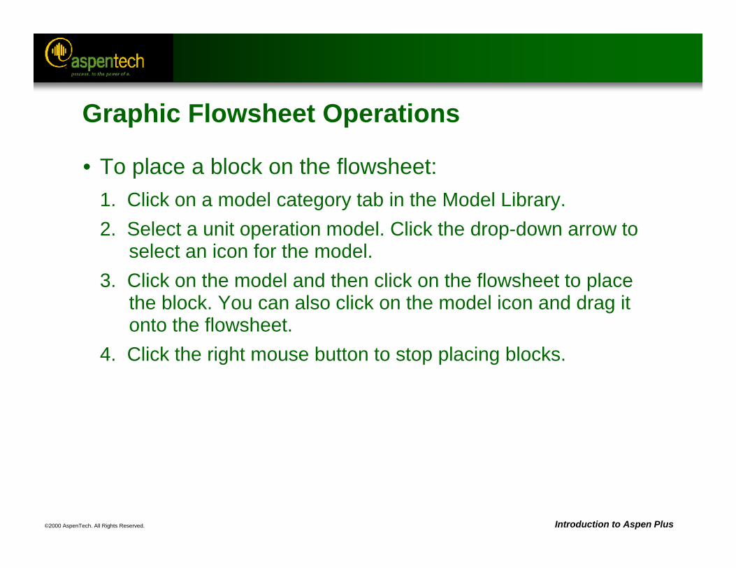
Graphic Flowsheet Operations
• To place a block on the flowsheet:1. Click on a model category tab in the Model Library.2. Select a unit operation model. Click the drop-down arrow to
select an icon for the model.3. Click on the model and then click on the flowsheet to place
the block. You can also click on the model icon and drag it onto the flowsheet.
4. Click the right mouse button to stop placing blocks.
©2000 AspenTech. All Rights Reserved. Introduction to Aspen Plus
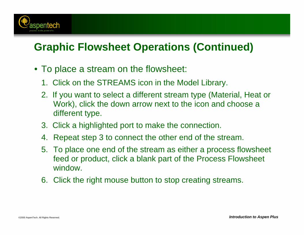
Graphic Flowsheet Operations (Continued)
• To place a stream on the flowsheet:1. Click on the STREAMS icon in the Model Library.2. If you want to select a different stream type (Material, Heat or
Work), click the down arrow next to the icon and choose a different type.
3. Click a highlighted port to make the connection.4. Repeat step 3 to connect the other end of the stream.5. To place one end of the stream as either a process flowsheet
feed or product, click a blank part of the Process Flowsheet window.
6. Click the right mouse button to stop creating streams.
©2000 AspenTech. All Rights Reserved. Introduction to Aspen Plus
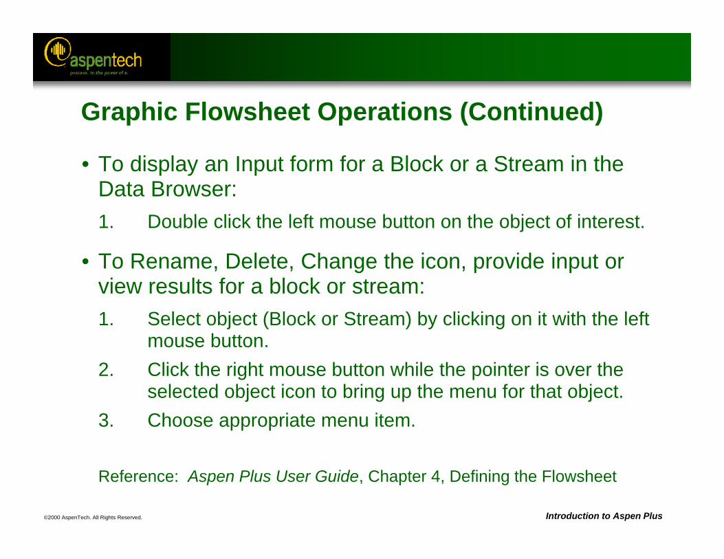
Graphic Flowsheet Operations (Continued)
• To display an Input form for a Block or a Stream in the Data Browser:1. Double click the left mouse button on the object of interest.
• To Rename, Delete, Change the icon, provide input or view results for a block or stream:1. Select object (Block or Stream) by clicking on it with the left
mouse button. 2. Click the right mouse button while the pointer is over the
selected object icon to bring up the menu for that object.3. Choose appropriate menu item.
Reference: Aspen Plus User Guide, Chapter 4, Defining the Flowsheet
©2000 AspenTech. All Rights Reserved. Introduction to Aspen Plus
Automatic Naming of Streams and Blocks
• Stream and block names can be automatically assigned by Aspen Plus or entered by the user when the object is created.
• Stream and block names can be displayed or hidden.
• To modify the naming options: – Select Options from the Tools menu.– Click the Flowsheet tab.– Check or uncheck the naming options desired.
©2000 AspenTech. All Rights Reserved. Introduction to Aspen Plus
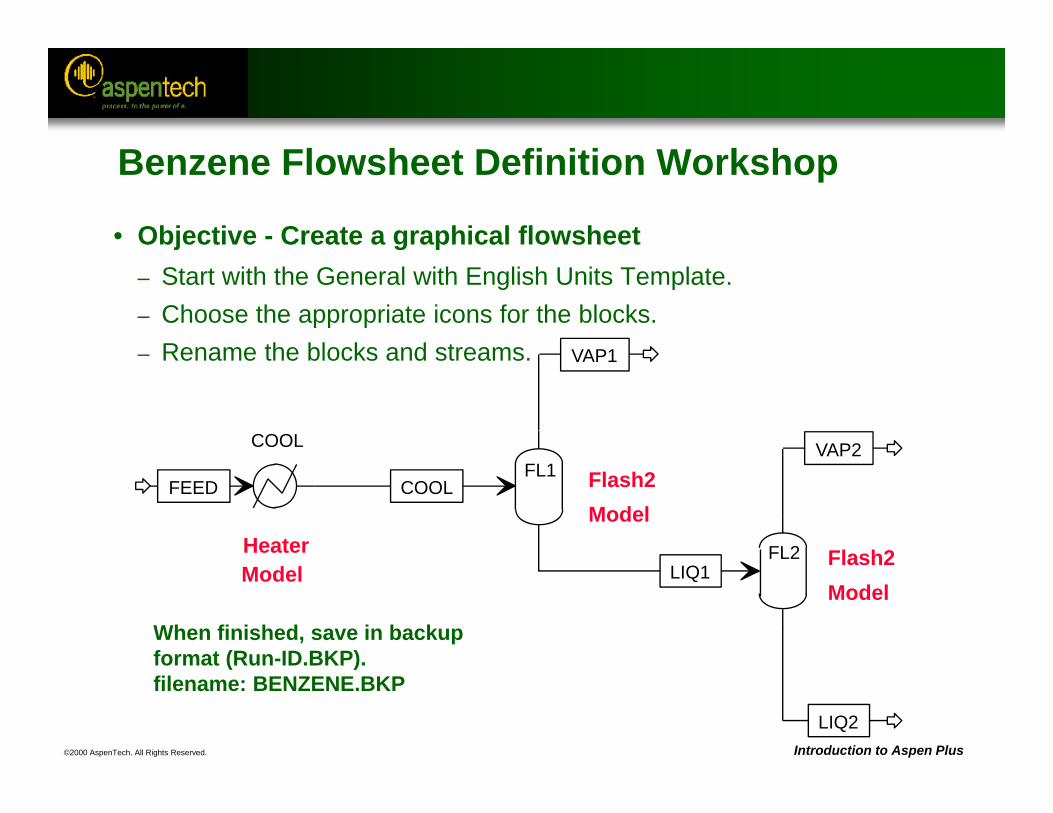
When finished, save in backup format (Run-ID.BKP).filename: BENZENE.BKP
FL1
HeaterModel
Flash2Model
Flash2Model
COOL
FEED COOL
VAP1
LIQ1FL2
VAP2
LIQ2
Benzene Flowsheet Definition Workshop
• Objective - Create a graphical flowsheet– Start with the General with English Units Template.– Choose the appropriate icons for the blocks.– Rename the blocks and streams.
©2000 AspenTech. All Rights Reserved.
Aspen Plus References:User Guide, Chapter 3, Using Aspen Plus HelpUser Guide, Chapter 5, Global Information for CalculationsUser Guide, Chapter 6, Specifying ComponentsUser Guide, Chapter 7, Physical Property MethodsUser Guide, Chapter 9, Specifying StreamsUser Guide, Chapter 10, Unit Operation ModelsUser Guide, Chapter 11, Running Your Simulation
Basic Input
Objective:Introduce the basic input required to run an Aspen
Plus simulation
©2000 AspenTech. All Rights Reserved. Introduction to Aspen Plus
The User Interface
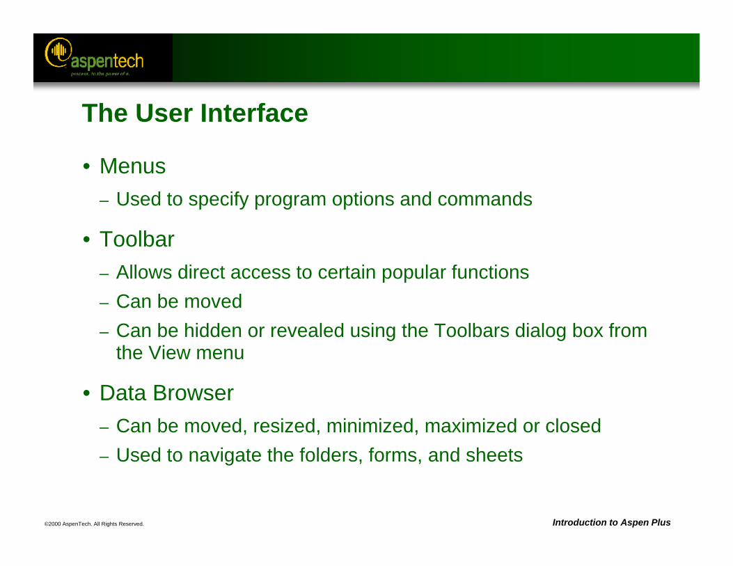
• Menus– Used to specify program options and commands
• Toolbar– Allows direct access to certain popular functions– Can be moved– Can be hidden or revealed using the Toolbars dialog box from
the View menu
• Data Browser– Can be moved, resized, minimized, maximized or closed – Used to navigate the folders, forms, and sheets
©2000 AspenTech. All Rights Reserved. Introduction to Aspen Plus
The User Interface (Continued)
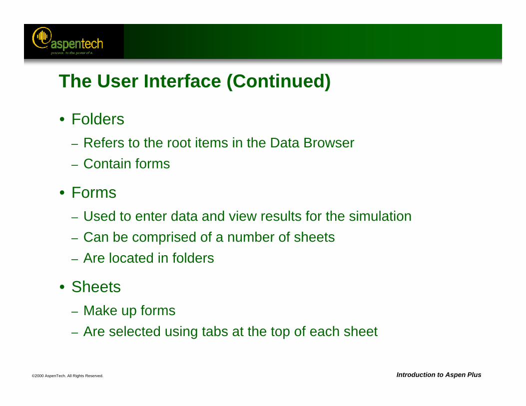
• Folders– Refers to the root items in the Data Browser– Contain forms
• Forms– Used to enter data and view results for the simulation– Can be comprised of a number of sheets – Are located in folders
• Sheets– Make up forms– Are selected using tabs at the top of each sheet
©2000 AspenTech. All Rights Reserved. Introduction to Aspen Plus
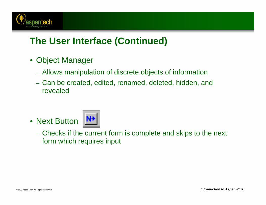
• Object Manager– Allows manipulation of discrete objects of information– Can be created, edited, renamed, deleted, hidden, and
revealed
• Next Button– Checks if the current form is complete and skips to the next
form which requires input
The User Interface (Continued)
©2000 AspenTech. All Rights Reserved. Introduction to Aspen Plus
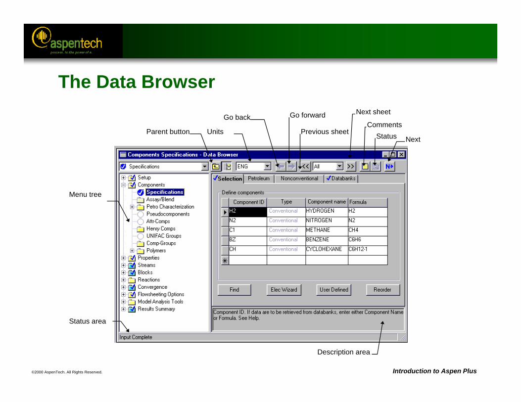
The Data Browser
Menu tree
Previous sheet
Next sheet
Status area
Parent button Units
Go back Go forwardComments
Next
Description area
Status
©2000 AspenTech. All Rights Reserved. Introduction to Aspen Plus
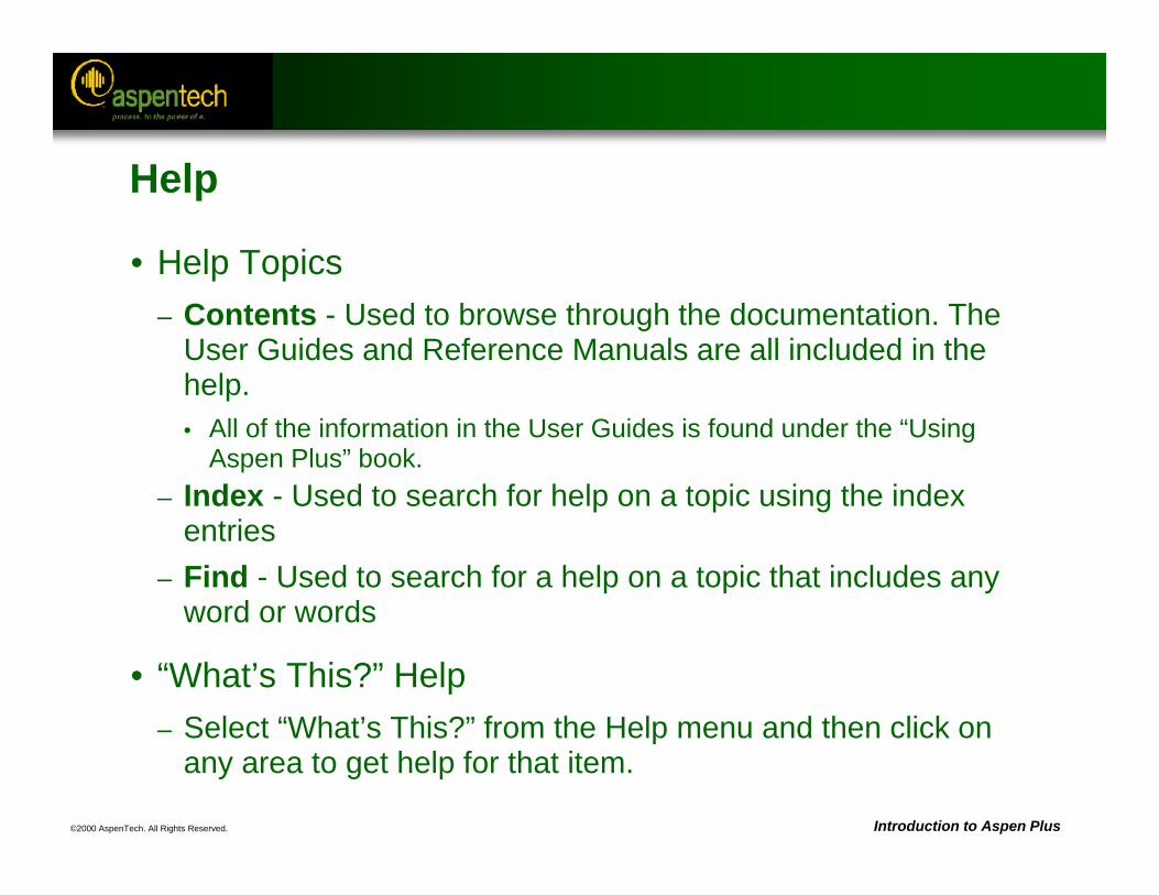
Help
• Help Topics– Contents - Used to browse through the documentation. The
User Guides and Reference Manuals are all included in the help.• All of the information in the User Guides is found under the “Using
Aspen Plus” book.– Index - Used to search for help on a topic using the index
entries– Find - Used to search for a help on a topic that includes any
word or words
• “What’s This?” Help– Select “What’s This?” from the Help menu and then click on
any area to get help for that item.
©2000 AspenTech. All Rights Reserved. Introduction to Aspen Plus
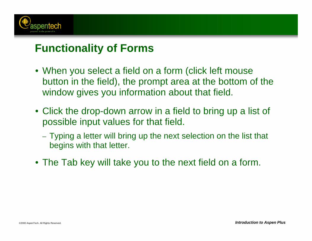
Functionality of Forms
• When you select a field on a form (click left mouse button in the field), the prompt area at the bottom of the window gives you information about that field.
• Click the drop-down arrow in a field to bring up a list of possible input values for that field.– Typing a letter will bring up the next selection on the list that
begins with that letter.
• The Tab key will take you to the next field on a form.
©2000 AspenTech. All Rights Reserved. Introduction to Aspen Plus
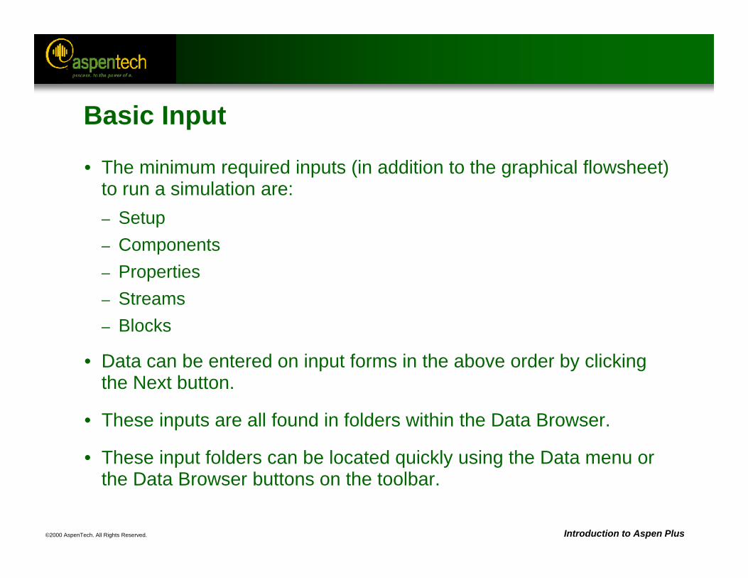
Basic Input
• The minimum required inputs (in addition to the graphical flowsheet) to run a simulation are:– Setup– Components– Properties– Streams– Blocks
• Data can be entered on input forms in the above order by clicking the Next button.
• These inputs are all found in folders within the Data Browser.
• These input folders can be located quickly using the Data menu or the Data Browser buttons on the toolbar.
©2000 AspenTech. All Rights Reserved. Introduction to Aspen Plus
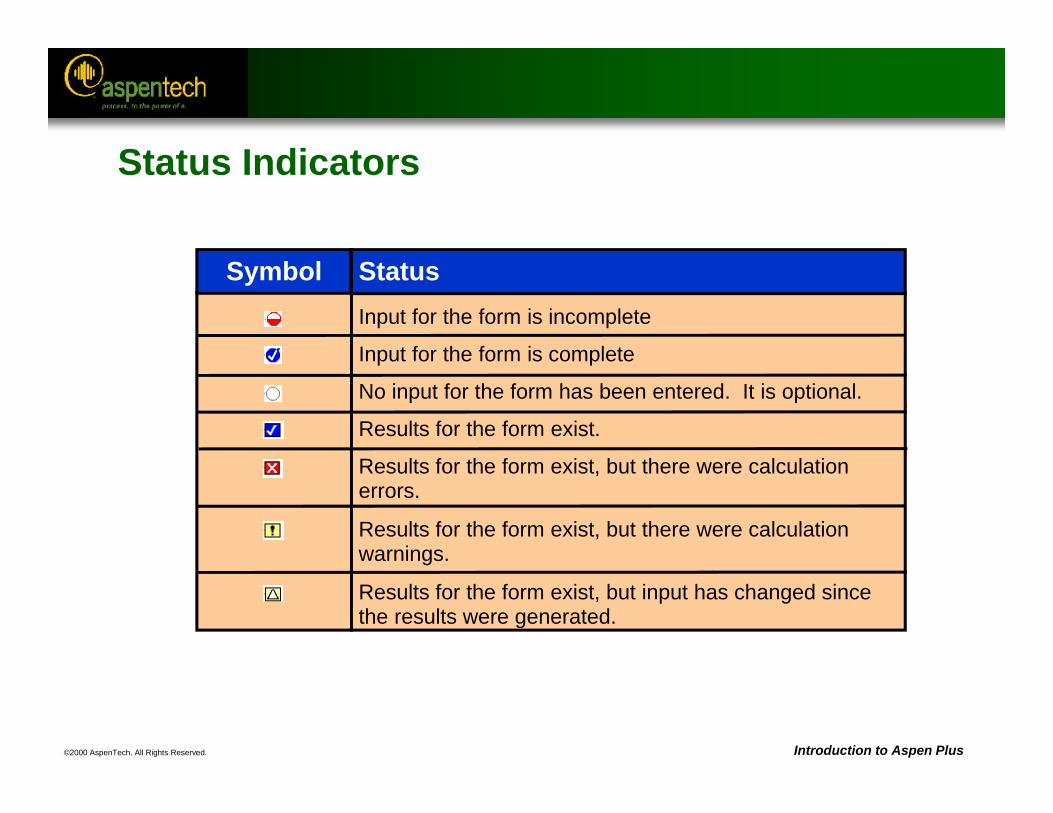
Status Indicators
Input for the form is incomplete
Input for the form is complete
No input for the form has been entered. It is optional.
Results for the form exist.
Results for the form exist, but there were calculationerrors.
Results for the form exist, but there were calculationwarnings.
Results for the form exist, but input has changed sincethe results were generated.
Symbol Status
©2000 AspenTech. All Rights Reserved. Introduction to Aspen Plus
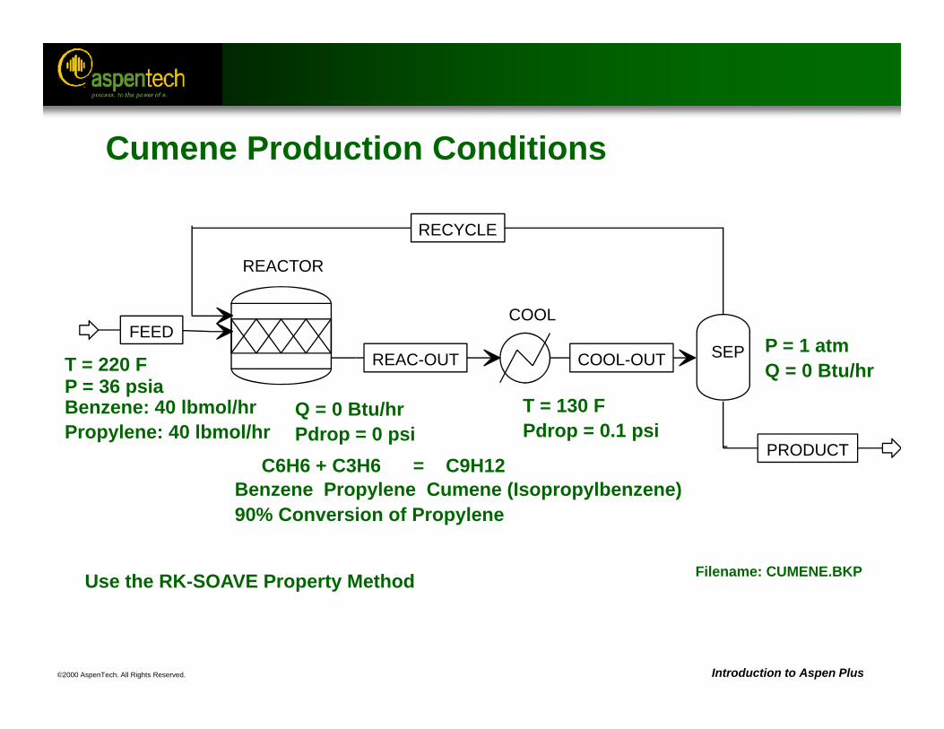
Cumene Production Conditions
Q = 0 Btu/hrPdrop = 0 psi
C6H6 + C3H6 = C9H12Benzene Propylene Cumene (Isopropylbenzene)90% Conversion of Propylene
T = 130 FPdrop = 0.1 psi
P = 1 atmQ = 0 Btu/hr
Benzene: 40 lbmol/hrPropylene: 40 lbmol/hr
T = 220 FP = 36 psia
Use the RK-SOAVE Property Method Filename: CUMENE.BKP
REACTOR
FEED
RECYCLE
REAC-OUT
COOL
COOL-OUT SEP
PRODUCT
©2000 AspenTech. All Rights Reserved. Introduction to Aspen Plus
Setup
• Most of the commonly used Setup information is entered on the Setup Specifications Global sheet:– Flowsheet title to be used on reports– Run type – Input and output units– Valid phases (e.g. vapor-liquid or vapor-liquid-liquid)– Ambient pressure
• Stream report options are located on the Setup Report Options Stream sheet.
©2000 AspenTech. All Rights Reserved. Introduction to Aspen Plus
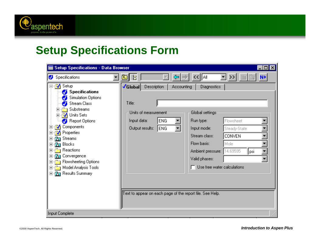
Setup Specifications Form
©2000 AspenTech. All Rights Reserved. Introduction to Aspen Plus
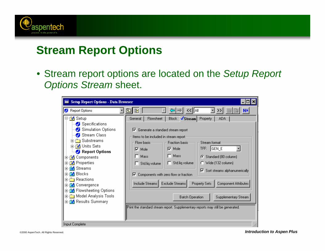
Stream Report Options
• Stream report options are located on the Setup Report Options Stream sheet.
©2000 AspenTech. All Rights Reserved. Introduction to Aspen Plus
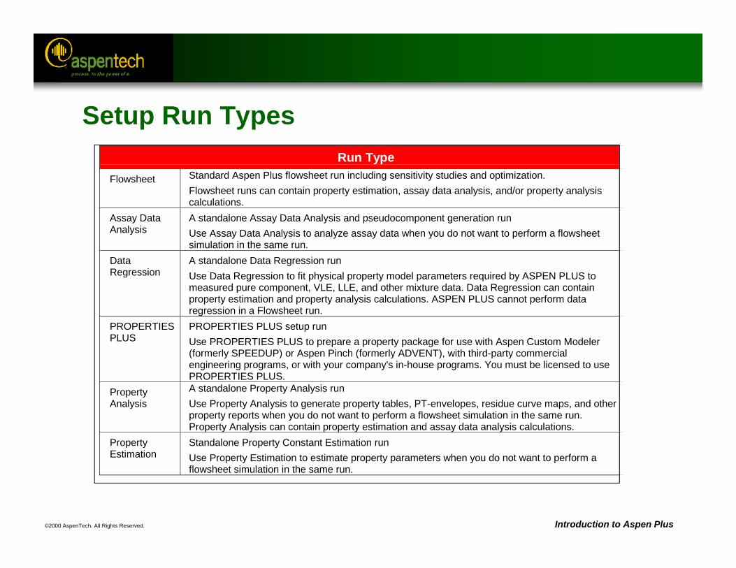
Setup Run TypesRun Type
Flowsheet Standard Aspen Plus flowsheet run including sensitivity studies and optimization.Flowsheet runs can contain property estimation, assay data analysis, and/or property analysiscalculations.
Assay DataAnalysis
A standalone Assay Data Analysis and pseudocomponent generation runUse Assay Data Analysis to analyze assay data when you do not want to perform a flowsheetsimulation in the same run.
DataRegression
A standalone Data Regression runUse Data Regression to fit physical property model parameters required by ASPEN PLUS tomeasured pure component, VLE, LLE, and other mixture data. Data Regression can containproperty estimation and property analysis calculations. ASPEN PLUS cannot perform dataregression in a Flowsheet run.
PROPERTIESPLUS
PROPERTIES PLUS setup runUse PROPERTIES PLUS to prepare a property package for use with Aspen Custom Modeler(formerly SPEEDUP) or Aspen Pinch (formerly ADVENT), with third-party commercialengineering programs, or with your company's in-house programs. You must be licensed to usePROPERTIES PLUS.
PropertyAnalysis
A standalone Property Analysis runUse Property Analysis to generate property tables, PT-envelopes, residue curve maps, and otherproperty reports when you do not want to perform a flowsheet simulation in the same run.Property Analysis can contain property estimation and assay data analysis calculations.
PropertyEstimation
Standalone Property Constant Estimation runUse Property Estimation to estimate property parameters when you do not want to perform aflowsheet simulation in the same run.
©2000 AspenTech. All Rights Reserved. Introduction to Aspen Plus
Setup Units
• Units in Aspen Plus can be defined at 3 different levels:1. Global Level (“Input Data” & “Output Results” fields on the
Setup Specifications Global sheet)2. Object level (“Units” field in the top of any input form of an
object such as a block or stream3. Field Level
• Users can create their own units sets using the Setup Units Sets Object Manager. Units can be copied from an existing set and then modified.
©2000 AspenTech. All Rights Reserved. Introduction to Aspen Plus
Components
• Use the Components Specifications form to specify all the components required for the simulation.
• If available, physical property parameters for each component are retrieved from databanks.
• Pure component databanks contain parameters such as molecular weight, critical properties, etc. The databank search order is specified on the Databanks sheet.
• The Find button can be used to search for components.
• The Electrolyte Wizard can be used to set up an electrolyte simulation.
©2000 AspenTech. All Rights Reserved. Introduction to Aspen Plus
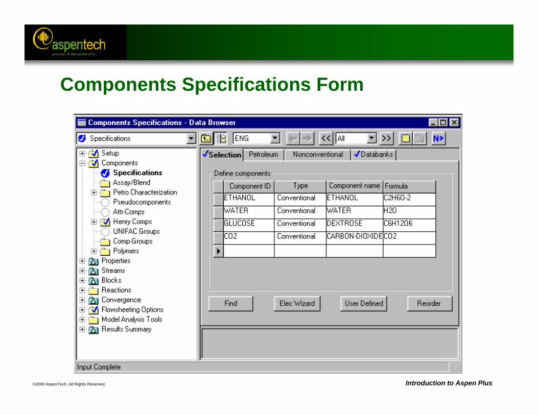
Components Specifications Form
©2000 AspenTech. All Rights Reserved. Introduction to Aspen Plus
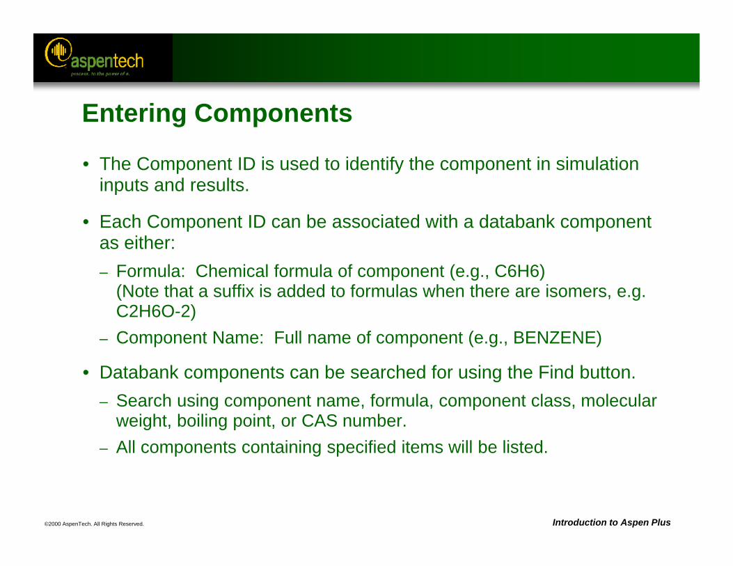
Entering Components
• The Component ID is used to identify the component in simulation inputs and results.
• Each Component ID can be associated with a databank component as either:– Formula: Chemical formula of component (e.g., C6H6)
(Note that a suffix is added to formulas when there are isomers, e.g. C2H6O-2)
– Component Name: Full name of component (e.g., BENZENE)
• Databank components can be searched for using the Find button.– Search using component name, formula, component class, molecular
weight, boiling point, or CAS number.– All components containing specified items will be listed.
©2000 AspenTech. All Rights Reserved. Introduction to Aspen Plus
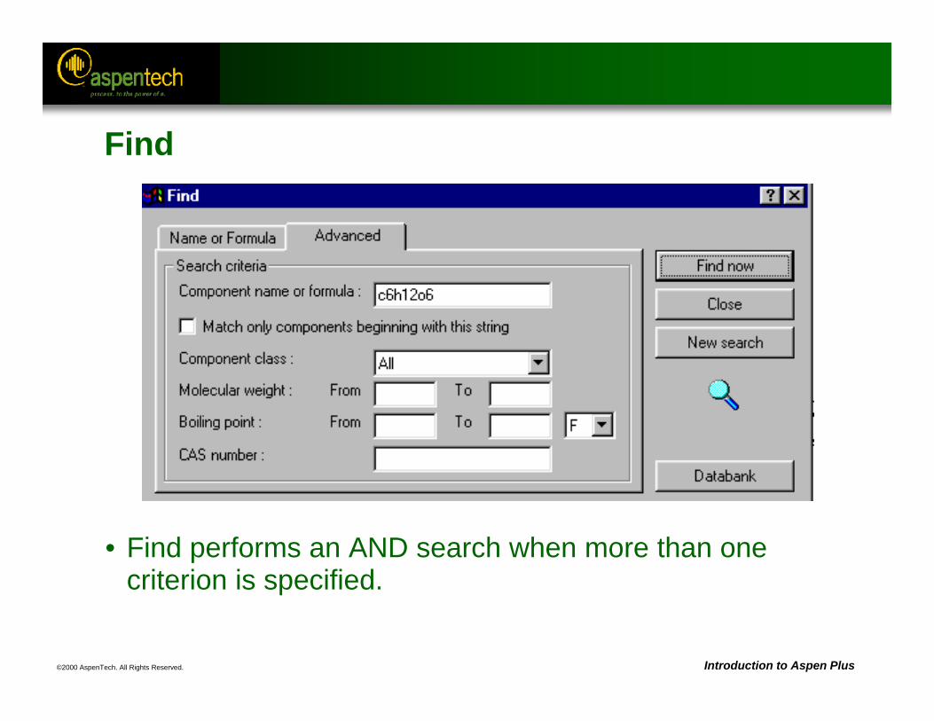
Find
• Find performs an AND search when more than one criterion is specified.
©2000 AspenTech. All Rights Reserved. Introduction to Aspen Plus
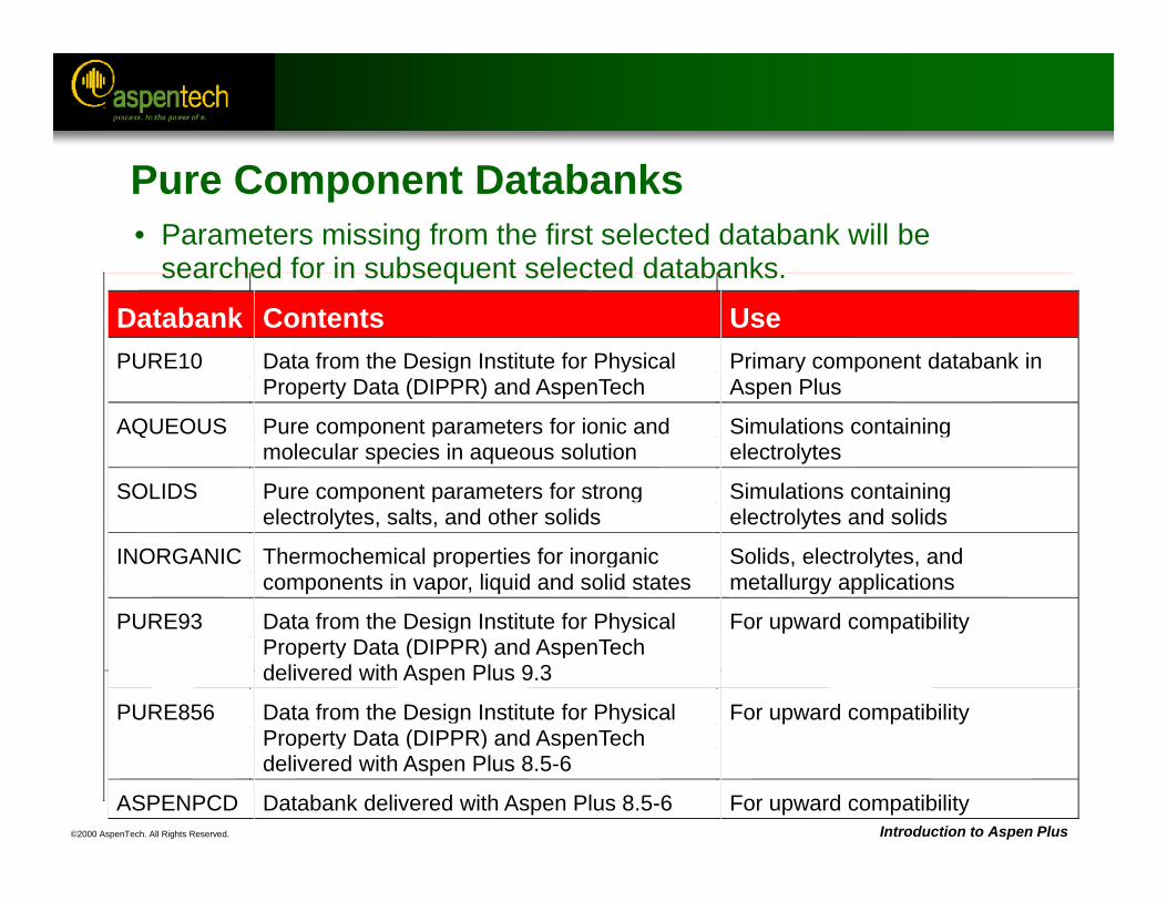
• Parameters missing from the first selected databank will be searched for in subsequent selected databanks.
Databank Contents UsePURE10 Data from the Design Institute for Physical
Property Data (DIPPR) and AspenTechPrimary component databank inAspen Plus
AQUEOUS Pure component parameters for ionic andmolecular species in aqueous solution
Simulations containingelectrolytes
SOLIDS Pure component parameters for strongelectrolytes, salts, and other solids
Simulations containingelectrolytes and solids
INORGANIC Thermochemical properties for inorganiccomponents in vapor, liquid and solid states
Solids, electrolytes, andmetallurgy applications
PURE93 Data from the Design Institute for PhysicalProperty Data (DIPPR) and AspenTechdelivered with Aspen Plus 9.3
For upward compatibility
PURE856 Data from the Design Institute for PhysicalProperty Data (DIPPR) and AspenTechdelivered with Aspen Plus 8.5-6
For upward compatibility
ASPENPCD Databank delivered with Aspen Plus 8.5-6 For upward compatibility
Pure Component Databanks
©2000 AspenTech. All Rights Reserved. Introduction to Aspen Plus
Properties
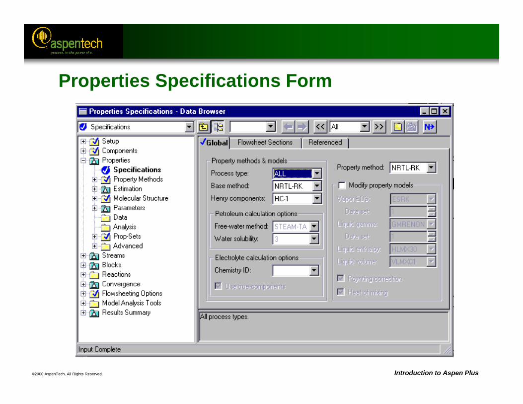
• Use the Properties Specifications form to specify the physical property methods to be used in the simulation.
• Property methods are a collection of models and methods used to describe pure component and mixture behavior.
• Choosing the right physical properties is critical for obtaining reliable simulation results.
• Selecting a Process Type will narrow the number of methods available.
©2000 AspenTech. All Rights Reserved. Introduction to Aspen Plus
Properties Specifications Form
©2000 AspenTech. All Rights Reserved. Introduction to Aspen Plus
Streams
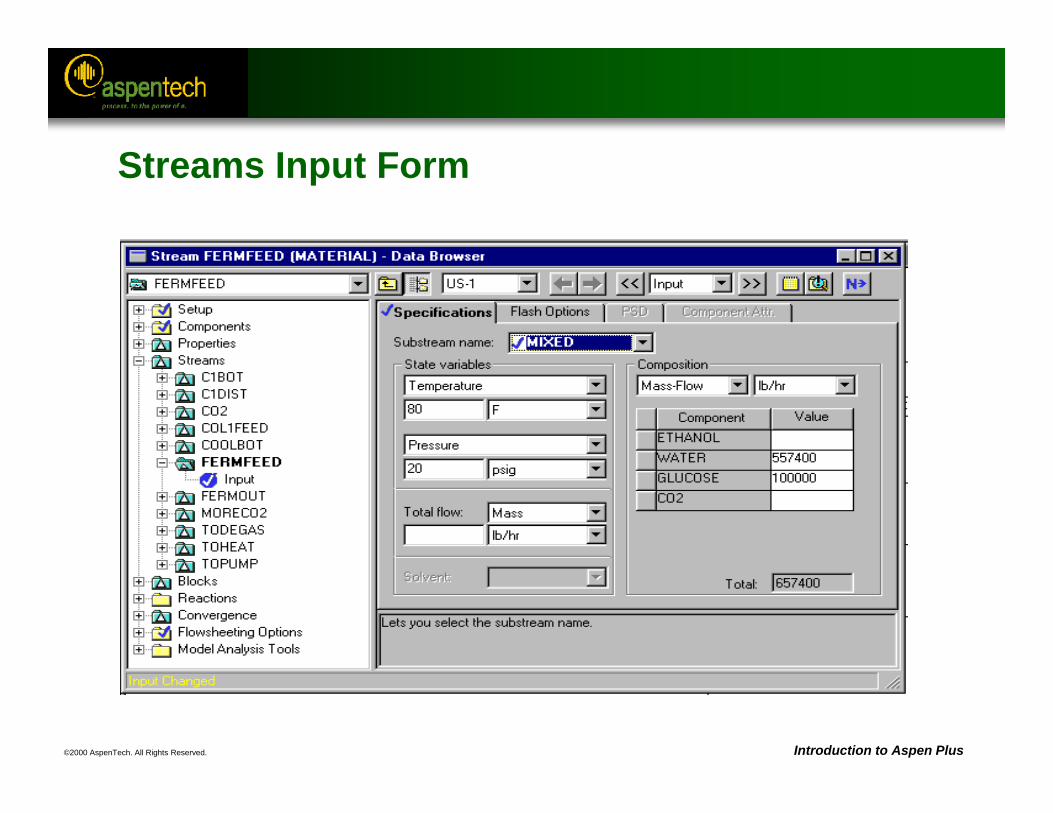
• Use Stream Input forms to specify the feed stream conditions and composition.
• To specify stream conditions enter two of the following:– Temperature– Pressure– Vapor Fraction
• To specify stream composition enter either:– Total stream flow and component fractions– Individual component flows
• Specifications for streams that are not feeds to the flowsheet are used as estimates.
©2000 AspenTech. All Rights Reserved. Introduction to Aspen Plus
Streams Input Form
©2000 AspenTech. All Rights Reserved. Introduction to Aspen Plus
Blocks
• Each Block Input or Block Setup form specifies operating conditions and equipment specifications for the unit operation model.
• Some unit operation models require additional specification forms
• All unit operation models have optional information forms (e.g. BlockOptions form).
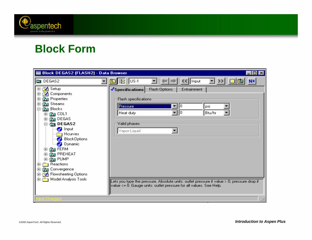
©2000 AspenTech. All Rights Reserved. Introduction to Aspen Plus
Block Form
©2000 AspenTech. All Rights Reserved. Introduction to Aspen Plus
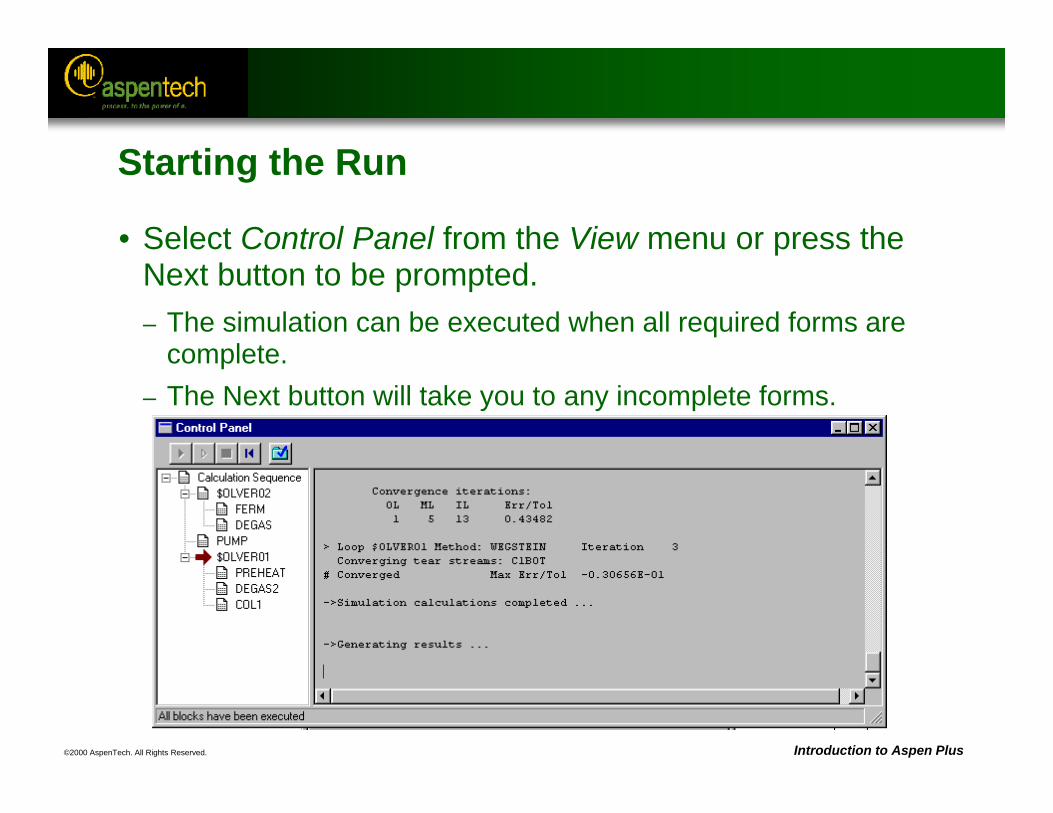
Starting the Run
• Select Control Panel from the View menu or press the Next button to be prompted.– The simulation can be executed when all required forms are
complete.– The Next button will take you to any incomplete forms.
©2000 AspenTech. All Rights Reserved. Introduction to Aspen Plus
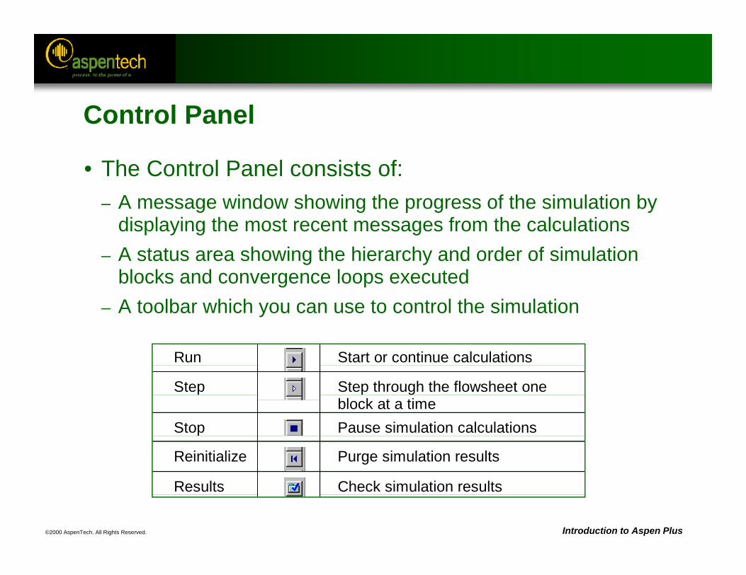
Run Start or continue calculations
Step Step through the flowsheet oneblock at a time
Stop Pause simulation calculations
Reinitialize Purge simulation results
Results Check simulation results
Control Panel
• The Control Panel consists of:– A message window showing the progress of the simulation by
displaying the most recent messages from the calculations– A status area showing the hierarchy and order of simulation
blocks and convergence loops executed– A toolbar which you can use to control the simulation
©2000 AspenTech. All Rights Reserved. Introduction to Aspen Plus
Reviewing Results
• History file or Control Panel Messages– Contains any generated errors or warnings– Select History or Control Panel on the View menu to display
the History file or the Control Panel
• Stream Results– Contains stream conditions and compositions
• For all streams (/Data/Results Summary/Streams)• For individual streams (bring up the stream folder in the Data Browser
and select the Results form)
• Block Results– Contains calculated block operating conditions (bring up the
block folder in the Data Browser and select the Results form)
©2000 AspenTech. All Rights Reserved. Introduction to Aspen Plus
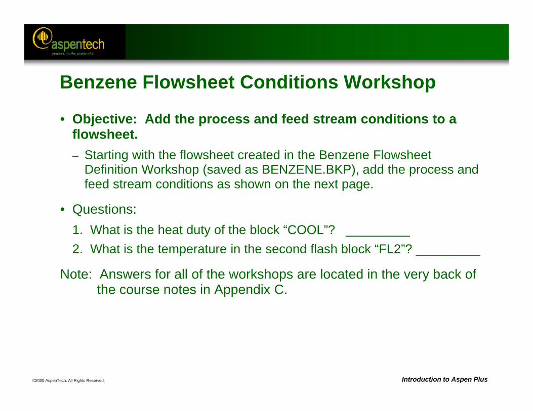
Benzene Flowsheet Conditions Workshop
• Objective: Add the process and feed stream conditions to a flowsheet.– Starting with the flowsheet created in the Benzene Flowsheet
Definition Workshop (saved as BENZENE.BKP), add the process and feed stream conditions as shown on the next page.
• Questions:1. What is the heat duty of the block “COOL”? _________2. What is the temperature in the second flash block “FL2”? _________
Note: Answers for all of the workshops are located in the very back of the course notes in Appendix C.
©2000 AspenTech. All Rights Reserved. Introduction to Aspen Plus
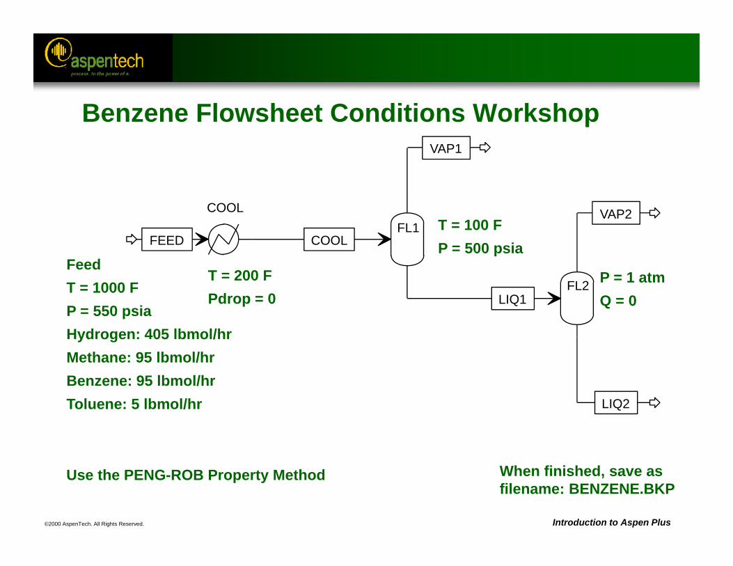
FeedT = 1000 FP = 550 psiaHydrogen: 405 lbmol/hrMethane: 95 lbmol/hrBenzene: 95 lbmol/hrToluene: 5 lbmol/hr
T = 200 FPdrop = 0
T = 100 FP = 500 psia
P = 1 atmQ = 0
Use the PENG-ROB Property Method When finished, save asfilename: BENZENE.BKP
FL1COOL
FEED COOL
VAP1
LIQ1FL2
VAP2
LIQ2
Benzene Flowsheet Conditions Workshop
©2000 AspenTech. All Rights Reserved.
Unit Operation Models
Objective:Review major types of unit operation models
Aspen Plus References:User Guide, Chapter 10, Unit Operation ModelsUnit Operation Models Reference Manual
©2000 AspenTech. All Rights Reserved. Introduction to Aspen Plus
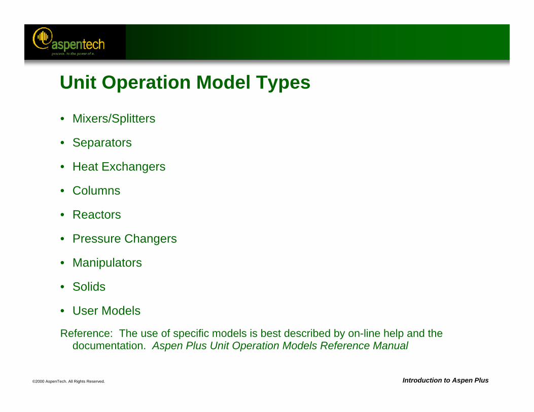
Unit Operation Model Types
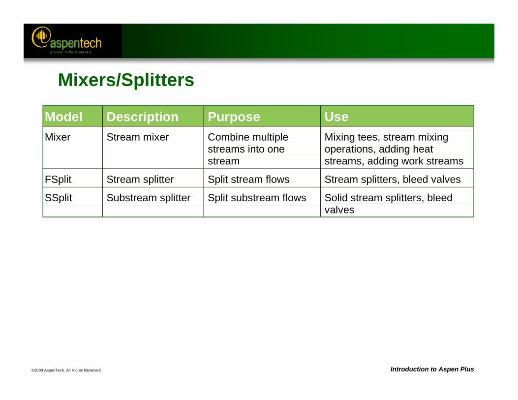
• Mixers/Splitters
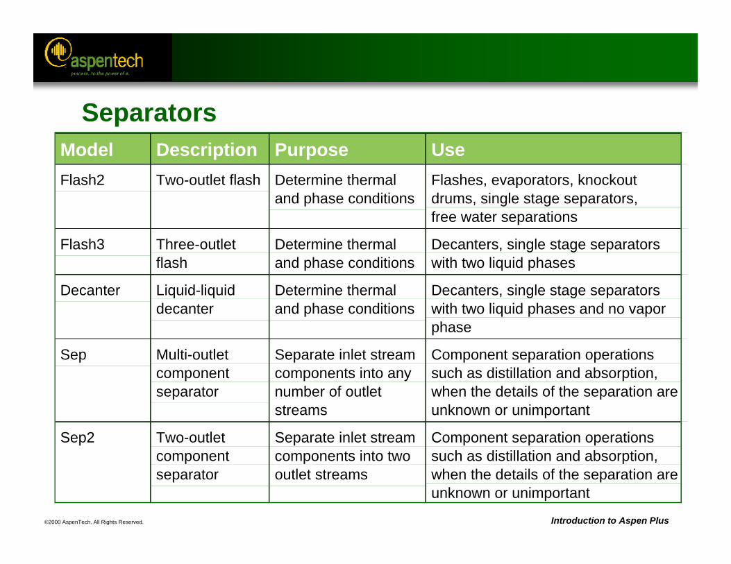
• Separators
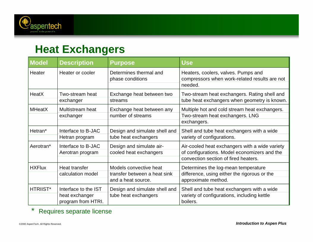
• Heat Exchangers
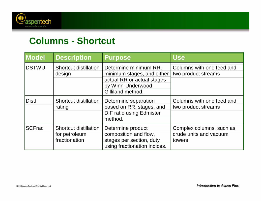
• Columns
• Reactors
• Pressure Changers
• Manipulators
• Solids
• User Models
Reference: The use of specific models is best described by on-line help and the documentation. Aspen Plus Unit Operation Models Reference Manual
©2000 AspenTech. All Rights Reserved. Introduction to Aspen Plus
Model Description Purpose UseMixer Stream mixer Combine multiple
streams into onestream
Mixing tees, stream mixingoperations, adding heatstreams, adding work streams
FSplit Stream splitter Split stream flows Stream splitters, bleed valves
SSplit Substream splitter Split substream flows Solid stream splitters, bleedvalves
Mixers/Splitters
©2000 AspenTech. All Rights Reserved. Introduction to Aspen Plus
Model Description Purpose UseFlash2 Two-outlet flash Determine thermal
and phase conditionsFlashes, evaporators, knockoutdrums, single stage separators,free water separations
Flash3 Three-outletflash
Determine thermaland phase conditions
Decanters, single stage separatorswith two liquid phases
Decanter Liquid-liquiddecanter
Determine thermaland phase conditions
Decanters, single stage separatorswith two liquid phases and no vaporphase
Sep Multi-outletcomponentseparator
Separate inlet streamcomponents into anynumber of outletstreams
Component separation operationssuch as distillation and absorption,when the details of the separation areunknown or unimportant
Sep2 Two-outletcomponentseparator
Separate inlet streamcomponents into twooutlet streams
Component separation operationssuch as distillation and absorption,when the details of the separation areunknown or unimportant
Separators
©2000 AspenTech. All Rights Reserved. Introduction to Aspen Plus
Heat Exchangers
* Requires separate license
Model Description Purpose UseHeater Heater or cooler Determines thermal and
phase conditionsHeaters, coolers, valves. Pumps andcompressors when work-related results are notneeded.
HeatX Two-stream heatexchanger
Exchange heat between twostreams
Two-stream heat exchangers. Rating shell andtube heat exchangers when geometry is known.
MHeatX Multistream heatexchanger
Exchange heat between anynumber of streams
Multiple hot and cold stream heat exchangers.Two-stream heat exchangers. LNGexchangers.
Hetran* Interface to B-JACHetran program
Design and simulate shell andtube heat exchangers
Shell and tube heat exchangers with a widevariety of configurations.
Aerotran* Interface to B-JACAerotran program
Design and simulate air-cooled heat exchangers
Air-cooled heat exchangers with a wide varietyof configurations. Model economizers and theconvection section of fired heaters.
HXFlux Heat transfercalculation model
Models convective heattransfer between a heat sinkand a heat source.
Determines the log-mean temperaturedifference, using either the rigorous or theapproximate method.
HTRIIST* Interface to the ISTheat exchangerprogram from HTRI.
Design and simulate shell andtube heat exchangers
Shell and tube heat exchangers with a widevariety of configurations, including kettleboilers.
©2000 AspenTech. All Rights Reserved. Introduction to Aspen Plus
Columns - ShortcutModel Description Purpose UseDSTWU Shortcut distillation
designDetermine minimum RR,minimum stages, and eitheractual RR or actual stagesby Winn-Underwood-Gilliland method.
Columns with one feed andtwo product streams
Distl Shortcut distillationrating
Determine separationbased on RR, stages, andD:F ratio using Edmistermethod.
Columns with one feed andtwo product streams
SCFrac Shortcut distillationfor petroleumfractionation
Determine productcomposition and flow,stages per section, dutyusing fractionation indices.
Complex columns, such ascrude units and vacuumtowers
©2000 AspenTech. All Rights Reserved. Introduction to Aspen Plus
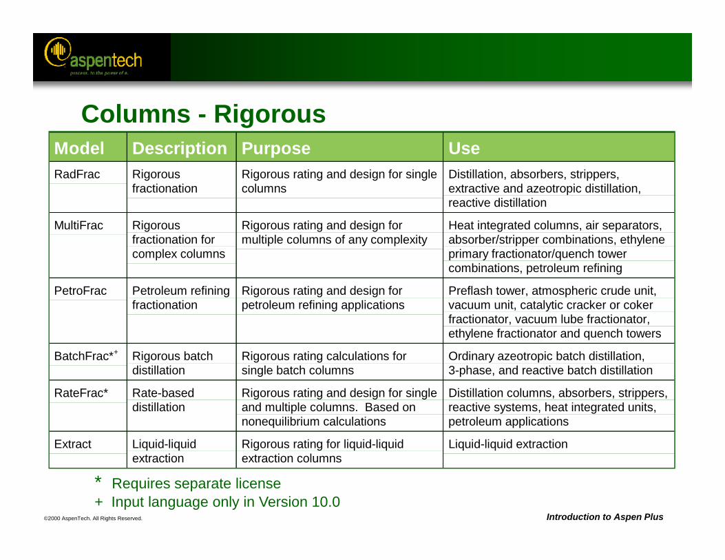
Columns - RigorousModel Description Purpose UseRadFrac Rigorous
fractionationRigorous rating and design for singlecolumns
Distillation, absorbers, strippers,extractive and azeotropic distillation,reactive distillation
MultiFrac Rigorousfractionation forcomplex columns
Rigorous rating and design formultiple columns of any complexity
Heat integrated columns, air separators,absorber/stripper combinations, ethyleneprimary fractionator/quench towercombinations, petroleum refining
PetroFrac Petroleum refiningfractionation
Rigorous rating and design forpetroleum refining applications
Preflash tower, atmospheric crude unit,vacuum unit, catalytic cracker or cokerfractionator, vacuum lube fractionator,ethylene fractionator and quench towers
BatchFrac*+ Rigorous batchdistillation
Rigorous rating calculations forsingle batch columns
Ordinary azeotropic batch distillation, 3-phase, and reactive batch distillation
RateFrac* Rate-baseddistillation
Rigorous rating and design for singleand multiple columns. Based onnonequilibrium calculations
Distillation columns, absorbers, strippers,reactive systems, heat integrated units,petroleum applications
Extract Liquid-liquidextraction
Rigorous rating for liquid-liquidextraction columns
Liquid-liquid extraction
* Requires separate license+ Input language only in Version 10.0
©2000 AspenTech. All Rights Reserved. Introduction to Aspen Plus
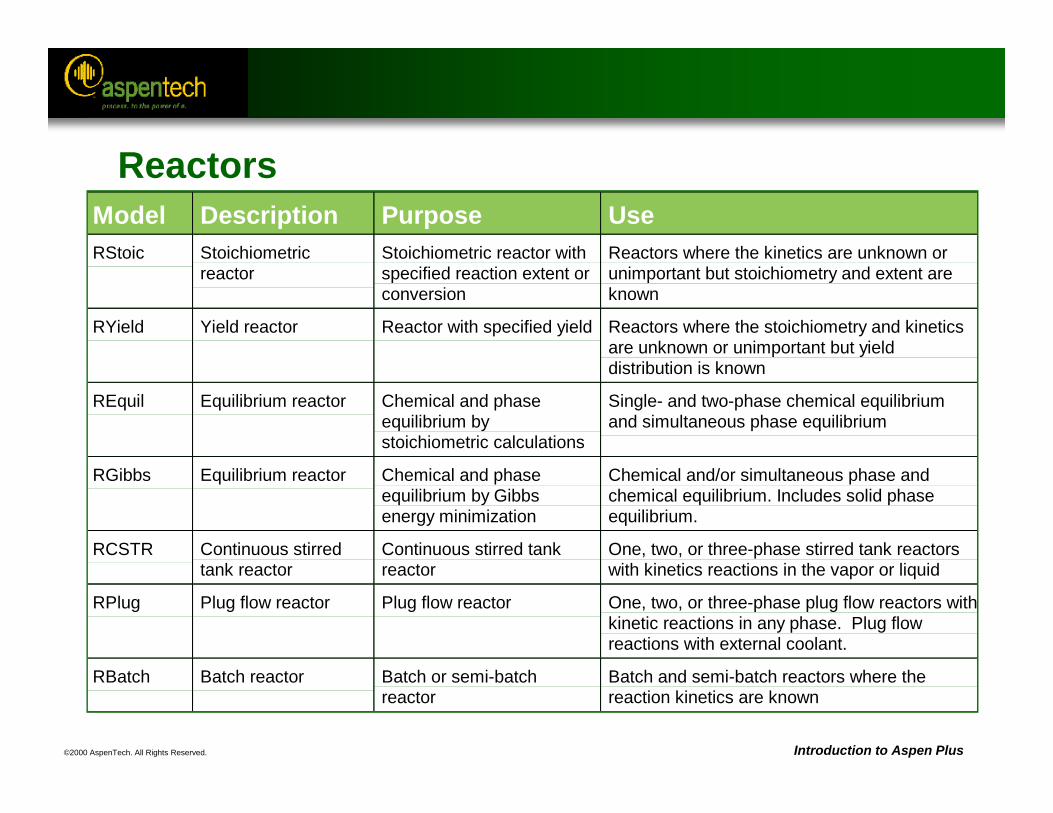
Model Description Purpose UseRStoic Stoichiometric
reactorStoichiometric reactor withspecified reaction extent orconversion
Reactors where the kinetics are unknown orunimportant but stoichiometry and extent areknown
RYield Yield reactor Reactor with specified yield Reactors where the stoichiometry and kineticsare unknown or unimportant but yielddistribution is known
REquil Equilibrium reactor Chemical and phaseequilibrium bystoichiometric calculations
Single- and two-phase chemical equilibriumand simultaneous phase equilibrium
RGibbs Equilibrium reactor Chemical and phaseequilibrium by Gibbsenergy minimization
Chemical and/or simultaneous phase andchemical equilibrium. Includes solid phaseequilibrium.
RCSTR Continuous stirredtank reactor
Continuous stirred tankreactor
One, two, or three-phase stirred tank reactorswith kinetics reactions in the vapor or liquid
RPlug Plug flow reactor Plug flow reactor One, two, or three-phase plug flow reactors withkinetic reactions in any phase. Plug flowreactions with external coolant.
RBatch Batch reactor Batch or semi-batchreactor
Batch and semi-batch reactors where thereaction kinetics are known
Reactors
©2000 AspenTech. All Rights Reserved. Introduction to Aspen Plus
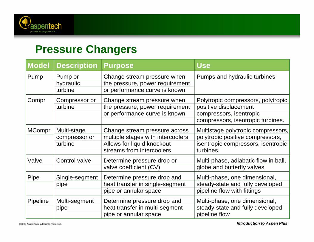
Pressure ChangersModel Description Purpose UsePump Pump or
hydraulicturbine
Change stream pressure whenthe pressure, power requirementor performance curve is known
Pumps and hydraulic turbines
Compr Compressor orturbine
Change stream pressure whenthe pressure, power requirementor performance curve is known
Polytropic compressors, polytropicpositive displacementcompressors, isentropiccompressors, isentropic turbines.
MCompr Multi-stagecompressor orturbine
Change stream pressure acrossmultiple stages with intercoolers.Allows for liquid knockoutstreams from intercoolers
Multistage polytropic compressors,polytropic positive compressors,isentropic compressors, isentropicturbines.
Valve Control valve Determine pressure drop orvalve coefficient (CV)
Multi-phase, adiabatic flow in ball,globe and butterfly valves
Pipe Single-segmentpipe
Determine pressure drop andheat transfer in single-segmentpipe or annular space
Multi-phase, one dimensional,steady-state and fully developedpipeline flow with fittings
Pipeline Multi-segmentpipe
Determine pressure drop andheat transfer in multi-segmentpipe or annular space
Multi-phase, one dimensional,steady-state and fully developedpipeline flow
©2000 AspenTech. All Rights Reserved. Introduction to Aspen Plus
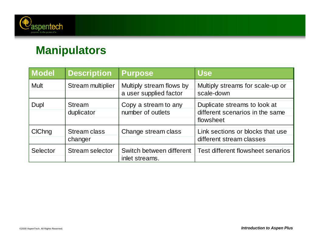
Manipulators
Model Description Purpose UseMult Stream multiplier Multiply stream flows by
a user supplied factorMultiply streams for scale-up orscale-down
Dupl Streamduplicator
Copy a stream to anynumber of outlets
Duplicate streams to look atdifferent scenarios in the sameflowsheet
ClChng Stream classchanger
Change stream class Link sections or blocks that usedifferent stream classes
Selector Stream selector Switch between differentinlet streams.
Test different flowsheet senarios
©2000 AspenTech. All Rights Reserved. Introduction to Aspen Plus
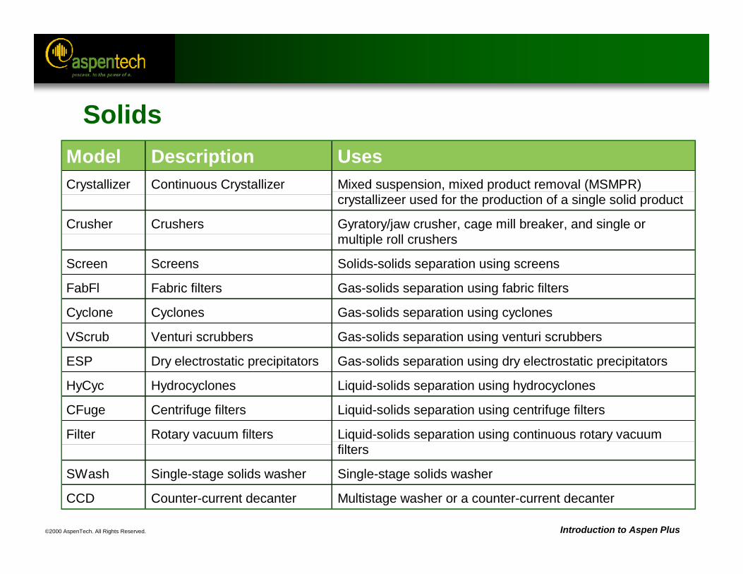
Model Description UsesCrystallizer Continuous Crystallizer Mixed suspension, mixed product removal (MSMPR)
crystallizeer used for the production of a single solid product
Crusher Crushers Gyratory/jaw crusher, cage mill breaker, and single ormultiple roll crushers
Screen Screens Solids-solids separation using screens
FabFl Fabric filters Gas-solids separation using fabric filters
Cyclone Cyclones Gas-solids separation using cyclones
VScrub Venturi scrubbers Gas-solids separation using venturi scrubbers
ESP Dry electrostatic precipitators Gas-solids separation using dry electrostatic precipitators
HyCyc Hydrocyclones Liquid-solids separation using hydrocyclones
CFuge Centrifuge filters Liquid-solids separation using centrifuge filters
Filter Rotary vacuum filters Liquid-solids separation using continuous rotary vacuumfilters
SWash Single-stage solids washer Single-stage solids washer
CCD Counter-current decanter Multistage washer or a counter-current decanter
Solids
©2000 AspenTech. All Rights Reserved. Introduction to Aspen Plus
User Models
• Proprietary models or 3-rd party software can be included in an Aspen Plus flowsheet using a User2 unit operation block.
• Excel Workbooks or Fortran code can be used to define the User2 unit operation model.
• User-defined names can be associated with variables.
• Variables can be dimensioned based on other input specifications (for example, number of components).
• Aspen Plus helper functions eliminate the need to know the internal data structure to retrieve variables.
©2000 AspenTech. All Rights Reserved.
Aspen Plus References:Unit Operation Models Reference Manual, Chapter 4, Columns
RadFrac
Objective:Discuss the minimum input required for the RadFrac fractionation model, and the use of design specifications and stage efficiencies
©2000 AspenTech. All Rights Reserved. Introduction to Aspen Plus
RadFrac: Rigorous Multistage Separation
• Vapor-Liquid or Vapor-Liquid-Liquid phase simulation of:– Ordinary distillation– Absorption, reboiled absorption– Stripping, reboiled stripping– Azeotropic distillation– Reactive distillation
• Configuration options:– Any number of feeds– Any number of side draws– Total liquid draw off and pumparounds– Any number of heaters– Any number of decanters
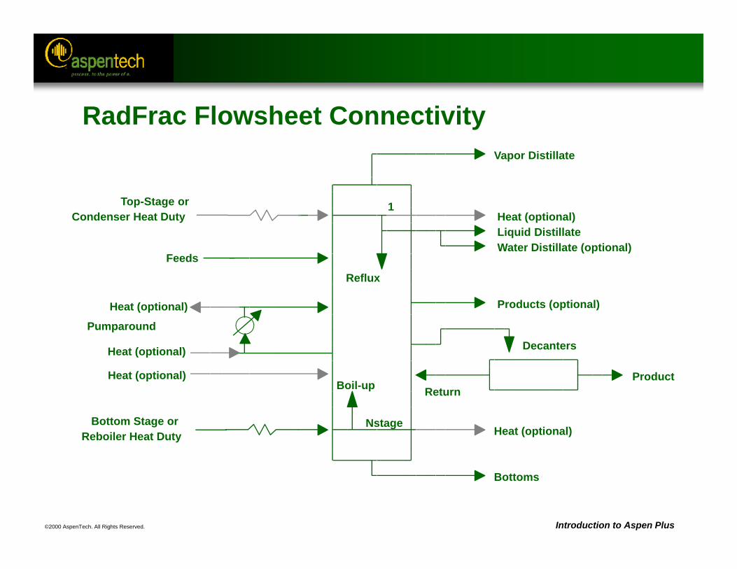
©2000 AspenTech. All Rights Reserved. Introduction to Aspen Plus
RadFrac Flowsheet ConnectivityVapor Distillate
Top-Stage or 1 Condenser Heat Duty Heat (optional)
Liquid DistillateWater Distillate (optional)
Feeds
Reflux
Products (optional)Heat (optional)
Pumparound DecantersHeat (optional)
ProductHeat (optional)ReturnBoil-up
Bottom Stage or NstageReboiler Heat Duty Heat (optional)
Bottoms
©2000 AspenTech. All Rights Reserved. Introduction to Aspen Plus
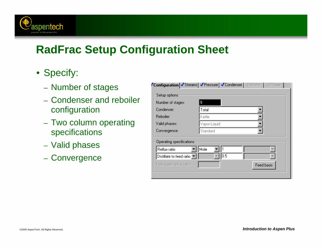
RadFrac Setup Configuration Sheet
• Specify:– Number of stages– Condenser and reboiler
configuration– Two column operating
specifications– Valid phases– Convergence
©2000 AspenTech. All Rights Reserved. Introduction to Aspen Plus
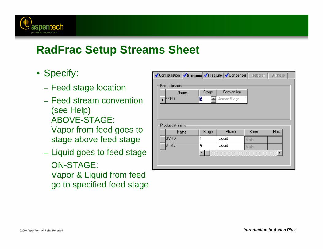
RadFrac Setup Streams Sheet
• Specify:– Feed stage location– Feed stream convention
(see Help)ABOVE-STAGE:Vapor from feed goes to stage above feed stage
– Liquid goes to feed stageON-STAGE:Vapor & Liquid from feed go to specified feed stage
©2000 AspenTech. All Rights Reserved. Introduction to Aspen Plus
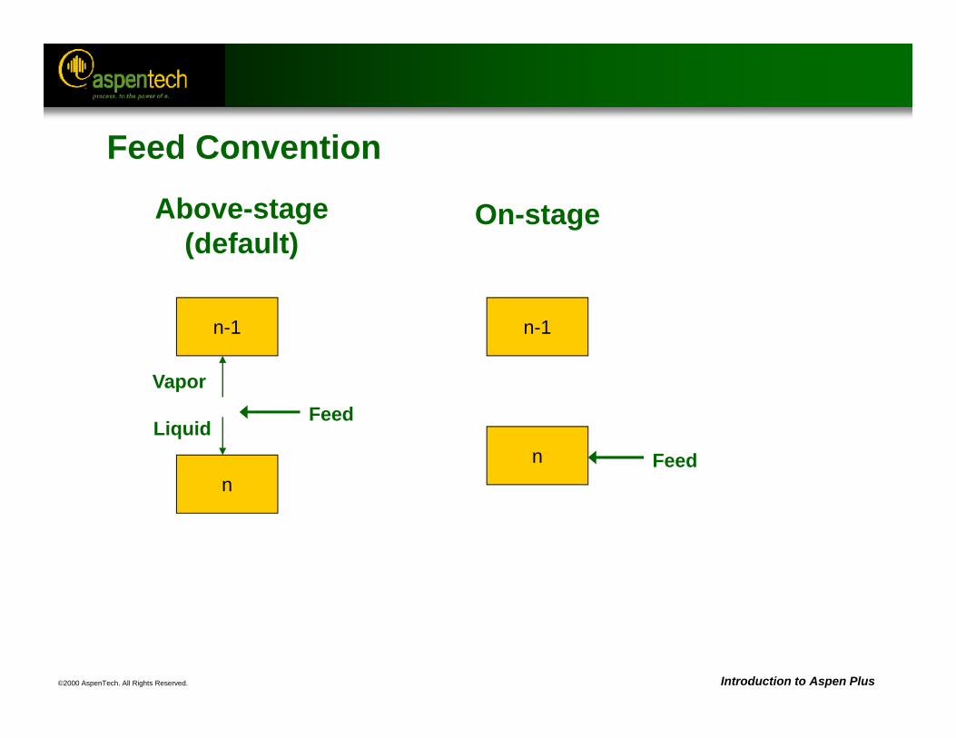
Feed Convention
On-stage
n
Above-stage (default)
n-1
n
VaporFeed
n-1
LiquidFeed
©2000 AspenTech. All Rights Reserved. Introduction to Aspen Plus
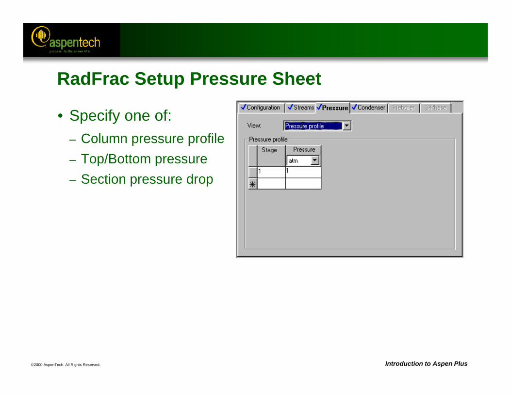
RadFrac Setup Pressure Sheet
• Specify one of:– Column pressure profile– Top/Bottom pressure– Section pressure drop
©2000 AspenTech. All Rights Reserved. Introduction to Aspen Plus
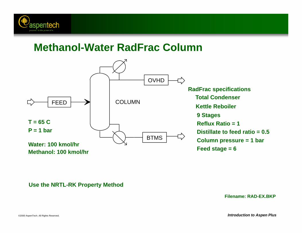
Kettle Reboiler
T = 65 CP = 1 bar
Water: 100 kmol/hrMethanol: 100 kmol/hr
9 StagesReflux Ratio = 1Distillate to feed ratio = 0.5Column pressure = 1 barFeed stage = 6
RadFrac specifications
Filename: RAD-EX.BKP
Methanol-Water RadFrac Column
Use the NRTL-RK Property Method
COLUMNFEED
OVHD
BTMS
Total Condenser
©2000 AspenTech. All Rights Reserved. Introduction to Aspen Plus
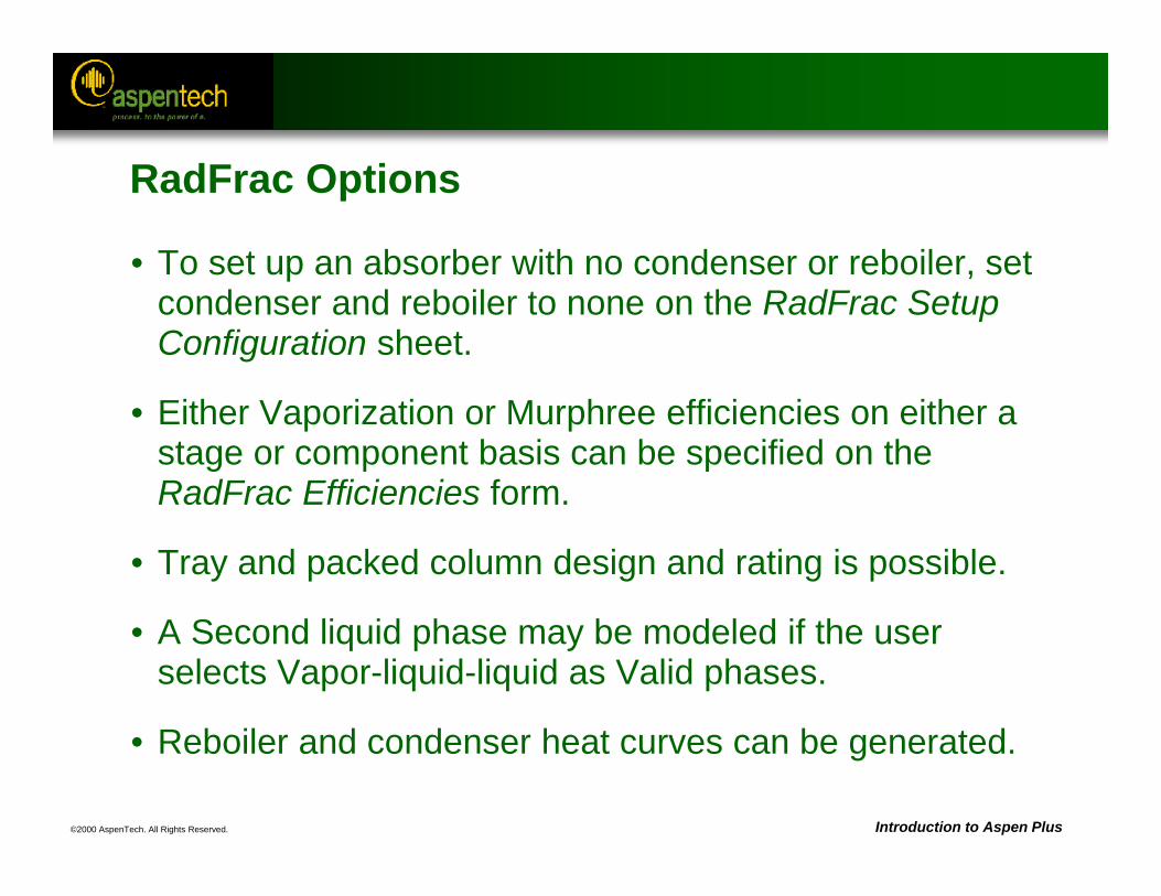
RadFrac Options
• To set up an absorber with no condenser or reboiler, set condenser and reboiler to none on the RadFrac Setup Configuration sheet.
• Either Vaporization or Murphree efficiencies on either a stage or component basis can be specified on the RadFrac Efficiencies form.
• Tray and packed column design and rating is possible.
• A Second liquid phase may be modeled if the user selects Vapor-liquid-liquid as Valid phases.
• Reboiler and condenser heat curves can be generated.
©2000 AspenTech. All Rights Reserved. Introduction to Aspen Plus
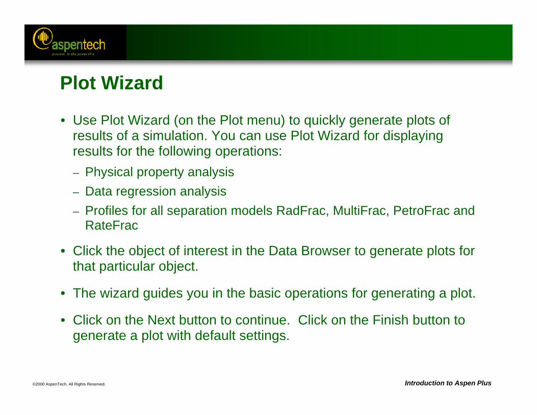
Plot Wizard
• Use Plot Wizard (on the Plot menu) to quickly generate plots of results of a simulation. You can use Plot Wizard for displaying results for the following operations:– Physical property analysis– Data regression analysis– Profiles for all separation models RadFrac, MultiFrac, PetroFrac and
RateFrac
• Click the object of interest in the Data Browser to generate plots for that particular object.
• The wizard guides you in the basic operations for generating a plot.
• Click on the Next button to continue. Click on the Finish button to generate a plot with default settings.
©2000 AspenTech. All Rights Reserved. Introduction to Aspen Plus
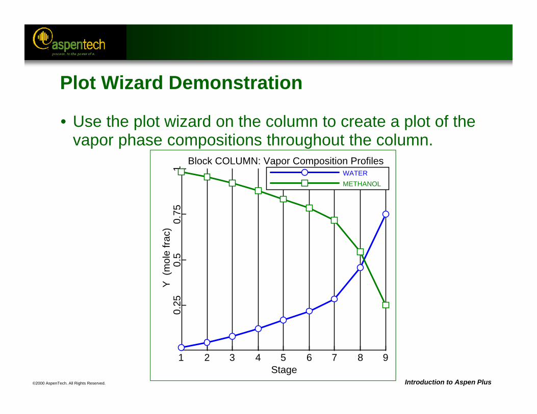
Block COLUMN: Vapor Composition Profiles
Stage1 2 3 4 5 6 7 8 9
Y (
mol
e fra
c)0.
250.
50.
751 WATER
METHANOL
Plot Wizard Demonstration
• Use the plot wizard on the column to create a plot of the vapor phase compositions throughout the column.
©2000 AspenTech. All Rights Reserved. Introduction to Aspen Plus
RadFrac DesignSpecs and Vary
• Design specifications can be specified and executed inside the RadFrac block using the DesignSpecs and Vary forms.
• One or more RadFrac inputs can be manipulated to achieve specifications on one or more RadFrac performance parameters.
• The number of specs should, in general, be equal to the number of varies.
• The DesignSpecs and Varys in a RadFrac are solved in a “Middle loop.” If you get an error message saying that the middle loop was not converged, check the DesignSpecs and Varys you have entered.
©2000 AspenTech. All Rights Reserved. Introduction to Aspen Plus
RadFrac Convergence Problems
• If a RadFrac column fails to converge, doing one or more of the following could help:
1. Check that physical property issues (choice of Property Method, parameter availability, etc.) are properly addressed.
2. Ensure that column operating conditions are feasible.
3. If the column err/tol is decreasing fairly consistently, increase the maximum iterations on the RadFrac Convergence Basicsheet.
©2000 AspenTech. All Rights Reserved. Introduction to Aspen Plus
RadFrac Convergence Problems (Continued)
4. Provide temperature estimates for some stages in the column using the RadFrac Estimates Temperaturesheet (useful for absorbers).
5. Provide composition estimates for some stages in the column using the RadFrac Estimates Liquid Composition and Vapor Composition sheet (useful for highly non-ideal systems).
6. Experiment with different convergence methods on the RadFrac Setup Configuration sheet.
Note: When a column does not converge, it is usually beneficial to Reinitialize after making changes.
©2000 AspenTech. All Rights Reserved. Introduction to Aspen Plus
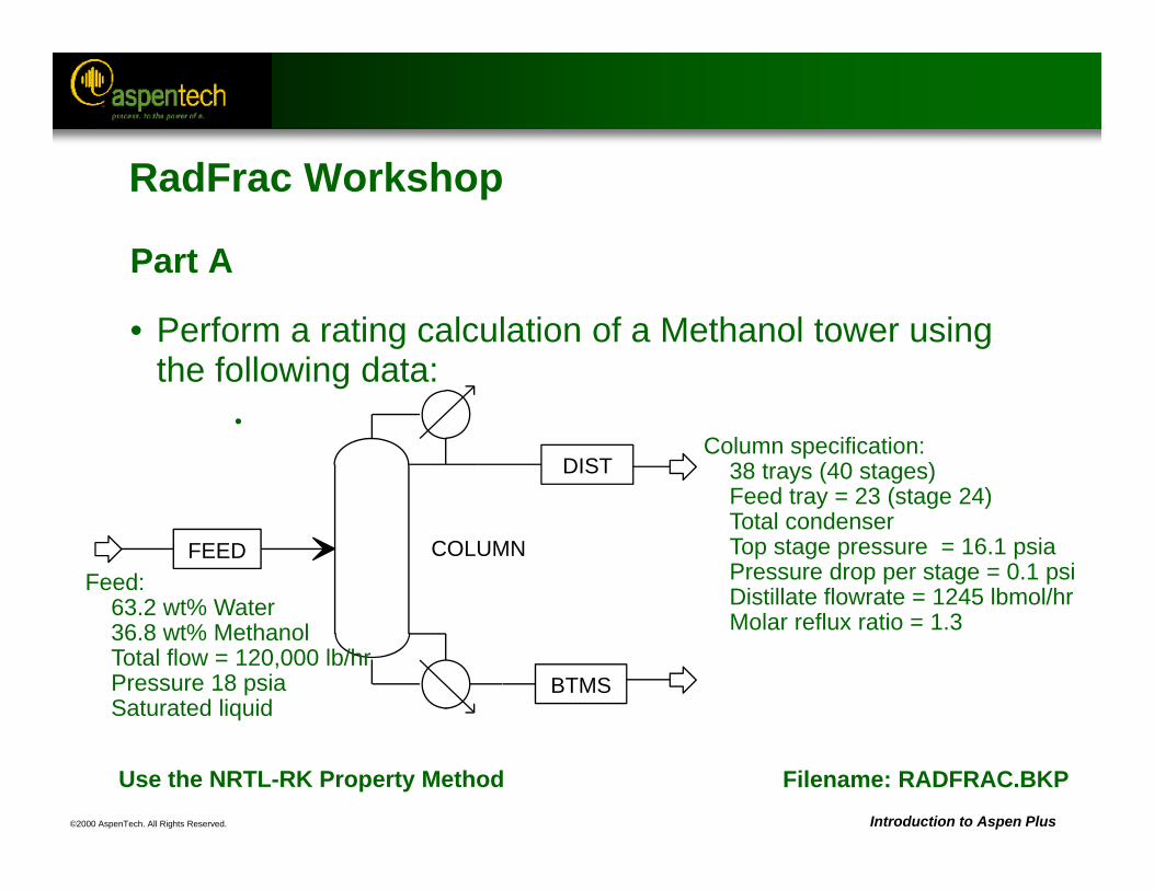
Filename: RADFRAC.BKPUse the NRTL-RK Property Method
COLUMNFEED
DIST
BTMS
Feed:63.2 wt% Water 36.8 wt% MethanolTotal flow = 120,000 lb/hrPressure 18 psia Saturated liquid
Column specification: 38 trays (40 stages)Feed tray = 23 (stage 24)Total condenserTop stage pressure = 16.1 psiaPressure drop per stage = 0.1 psiDistillate flowrate = 1245 lbmol/hrMolar reflux ratio = 1.3
RadFrac Workshop
Part A
• Perform a rating calculation of a Methanol tower using the following data:
•
©2000 AspenTech. All Rights Reserved. Introduction to Aspen Plus
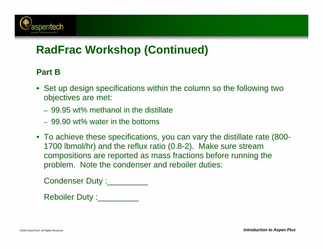
RadFrac Workshop (Continued)
Part B
• Set up design specifications within the column so the following two objectives are met:– 99.95 wt% methanol in the distillate– 99.90 wt% water in the bottoms
• To achieve these specifications, you can vary the distillate rate (800-1700 lbmol/hr) and the reflux ratio (0.8-2). Make sure stream compositions are reported as mass fractions before running the problem. Note the condenser and reboiler duties:
Condenser Duty :_________
Reboiler Duty :_________
©2000 AspenTech. All Rights Reserved. Introduction to Aspen Plus
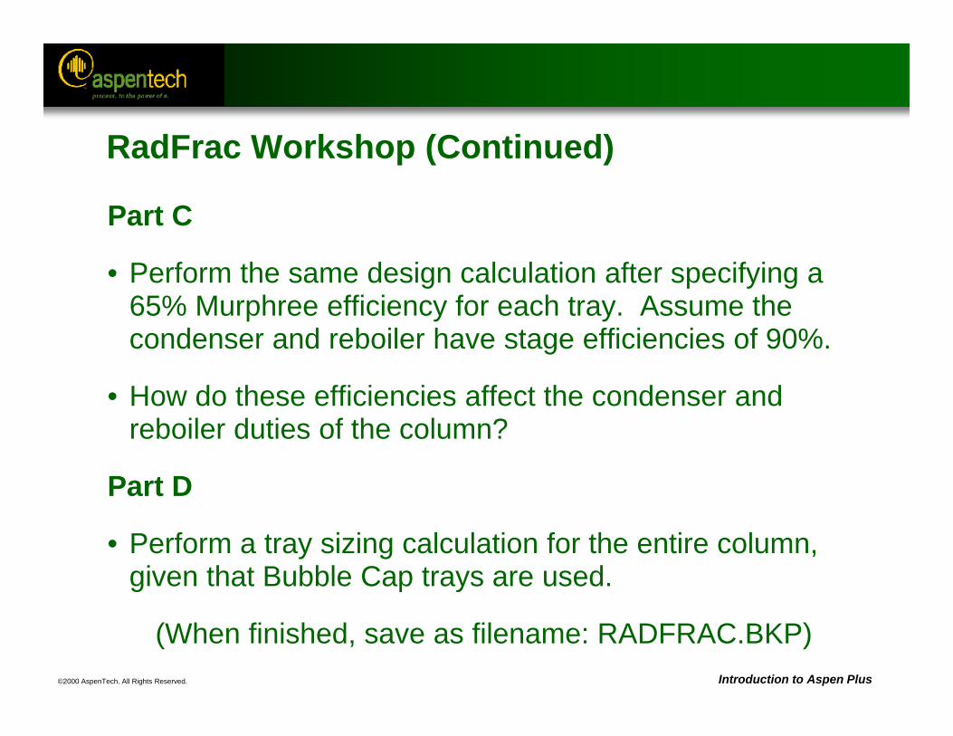
RadFrac Workshop (Continued)
Part C
• Perform the same design calculation after specifying a 65% Murphree efficiency for each tray. Assume the condenser and reboiler have stage efficiencies of 90%.
• How do these efficiencies affect the condenser and reboiler duties of the column?
Part D
• Perform a tray sizing calculation for the entire column, given that Bubble Cap trays are used.
(When finished, save as filename: RADFRAC.BKP)
©2000 AspenTech. All Rights Reserved.
Reactor Models
Objective:Introduce the various classes of reactor models
available, and examine in some detail at least one reactor from each class
Aspen Plus ReferencesUnit Operation Models Reference Manual, Chapter 5, Reactors
©2000 AspenTech. All Rights Reserved. Introduction to Aspen Plus
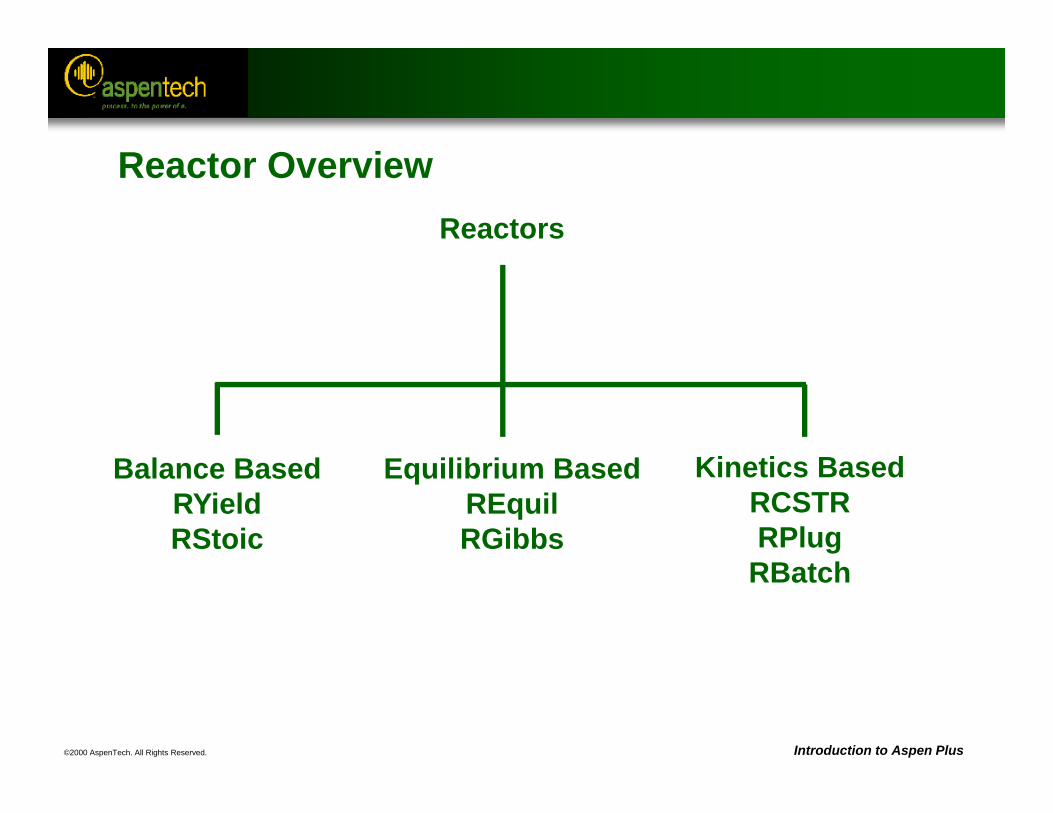
Reactor OverviewReactors
Balance BasedRYieldRStoic
Equilibrium BasedREquilRGibbs
Kinetics BasedRCSTRRPlug
RBatch
©2000 AspenTech. All Rights Reserved. Introduction to Aspen Plus
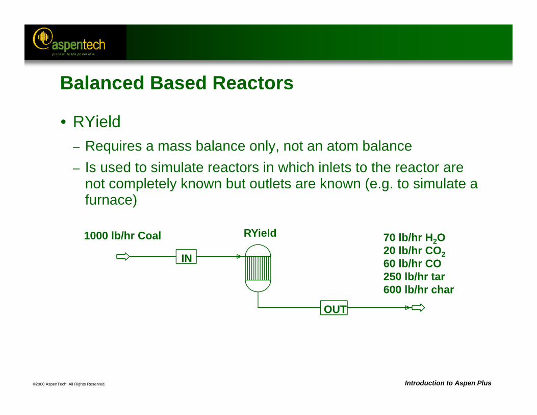
70 lb/hr H2O20 lb/hr CO260 lb/hr CO250 lb/hr tar600 lb/hr char
1000 lb/hr Coal
IN
OUT
RYield
Balanced Based Reactors
• RYield– Requires a mass balance only, not an atom balance– Is used to simulate reactors in which inlets to the reactor are
not completely known but outlets are known (e.g. to simulate a furnace)
©2000 AspenTech. All Rights Reserved. Introduction to Aspen Plus
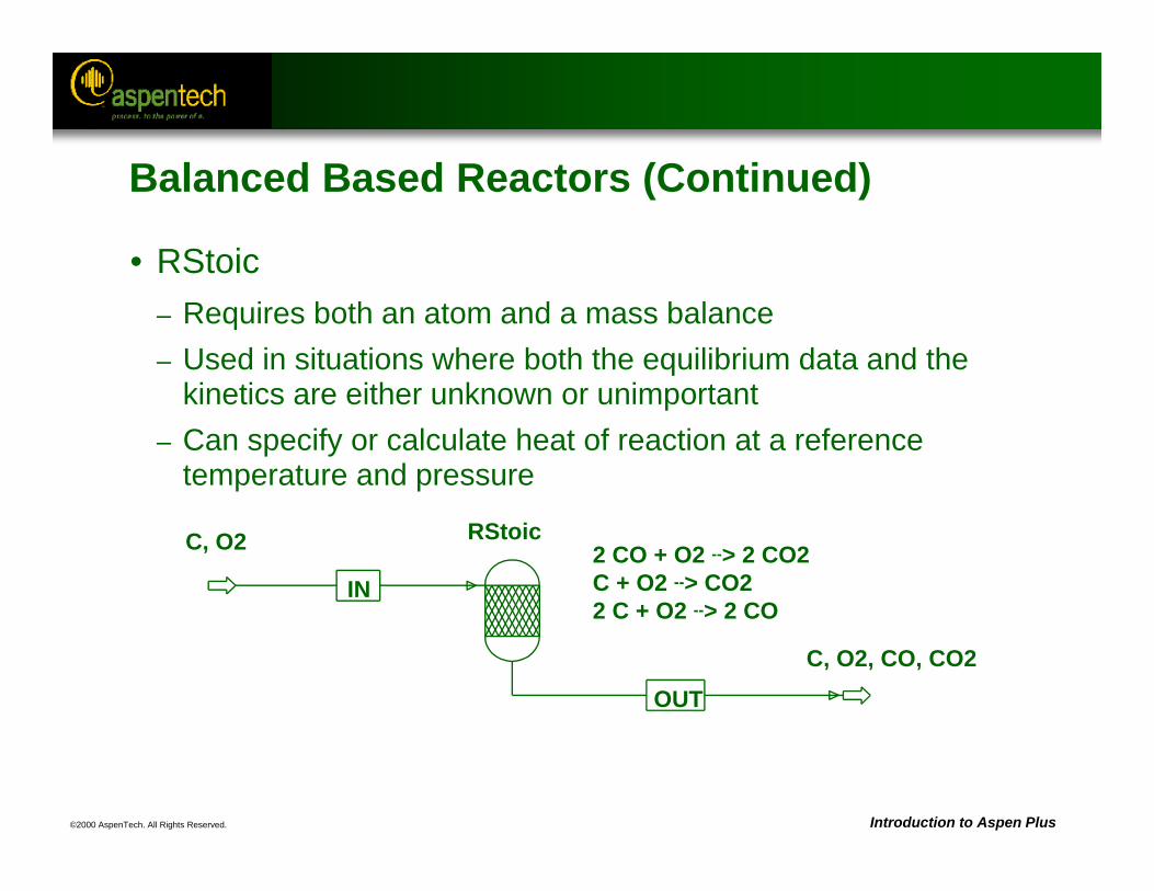
2 CO + O2 --> 2 CO2C + O2 --> CO22 C + O2 --> 2 CO
C, O2
IN
OUT
RStoic
C, O2, CO, CO2
Balanced Based Reactors (Continued)
• RStoic– Requires both an atom and a mass balance– Used in situations where both the equilibrium data and the
kinetics are either unknown or unimportant– Can specify or calculate heat of reaction at a reference
temperature and pressure
©2000 AspenTech. All Rights Reserved. Introduction to Aspen Plus
Equilibrium Based Reactors
• GENERAL– Do not take reaction kinetics into account– Solve similar problems, but problem specifications are different– Individual reactions can be at a restricted equilibrium
• REquil– Computes combined chemical and phase equilibrium by
solving reaction equilibrium equations– Cannot do a 3-phase flash– Useful when there are many components, a few known
reactions, and when relatively few components take part in the reactions
©2000 AspenTech. All Rights Reserved. Introduction to Aspen Plus
Equilibrium Based Reactors (Continued)
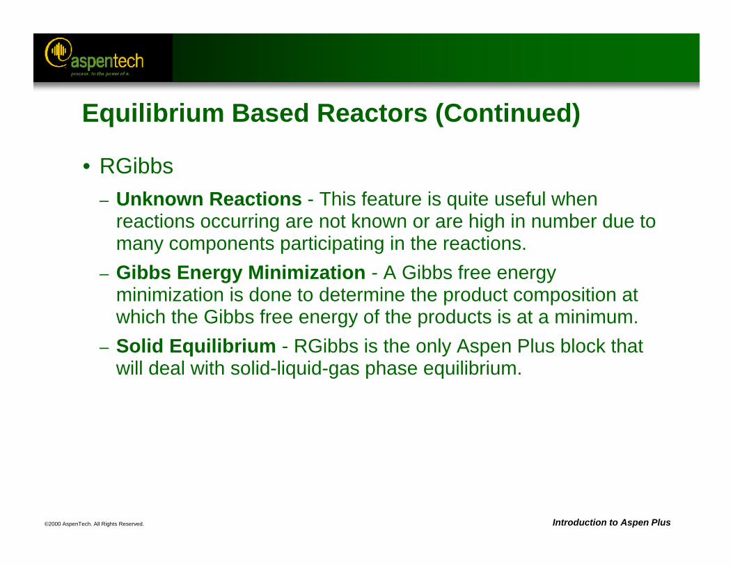
• RGibbs– Unknown Reactions - This feature is quite useful when
reactions occurring are not known or are high in number due to many components participating in the reactions.
– Gibbs Energy Minimization - A Gibbs free energy minimization is done to determine the product composition at which the Gibbs free energy of the products is at a minimum.
– Solid Equilibrium - RGibbs is the only Aspen Plus block that will deal with solid-liquid-gas phase equilibrium.
©2000 AspenTech. All Rights Reserved. Introduction to Aspen Plus
Kinetic Reactors
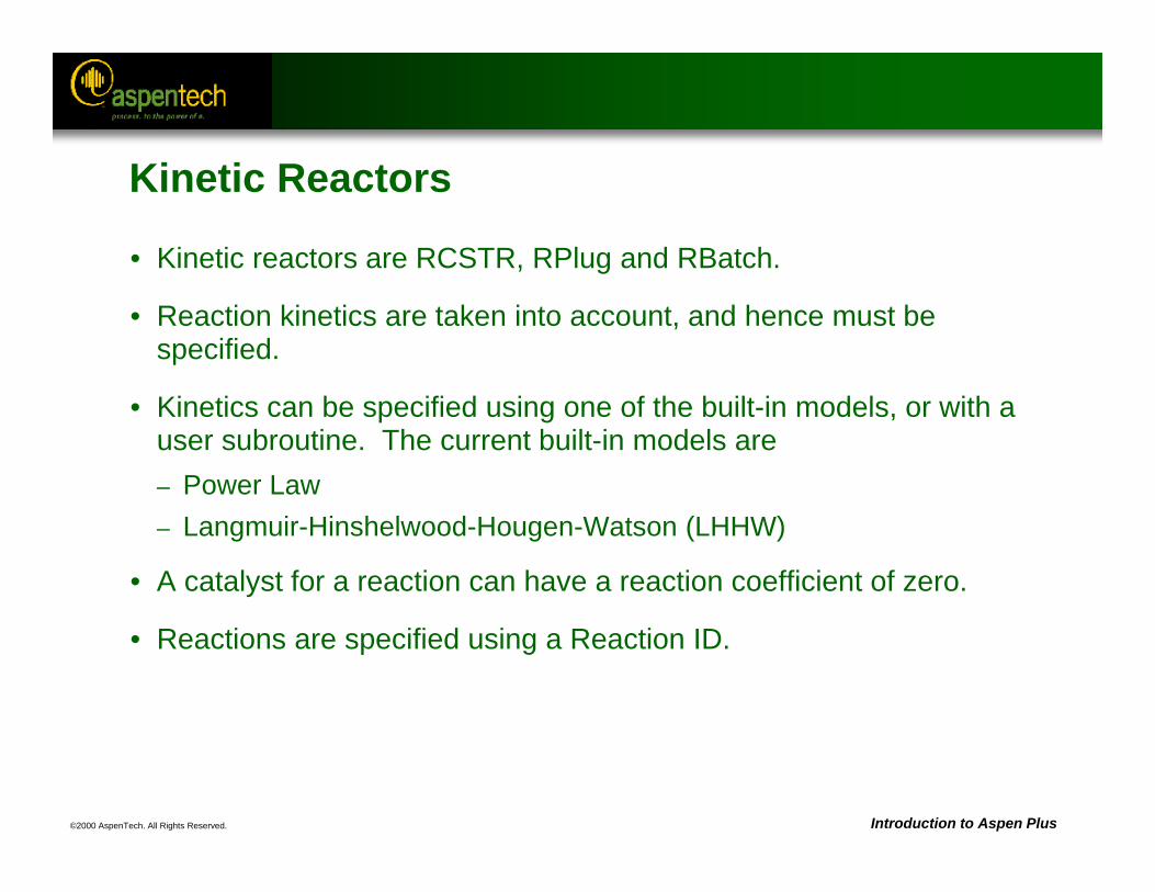
• Kinetic reactors are RCSTR, RPlug and RBatch.
• Reaction kinetics are taken into account, and hence must be specified.
• Kinetics can be specified using one of the built-in models, or with a user subroutine. The current built-in models are– Power Law– Langmuir-Hinshelwood-Hougen-Watson (LHHW)
• A catalyst for a reaction can have a reaction coefficient of zero.
• Reactions are specified using a Reaction ID.
©2000 AspenTech. All Rights Reserved. Introduction to Aspen Plus
Using a Reaction ID
• Reaction IDs are setup as objects, separate from the reactor, and then referenced within the reactor(s).
• A single Reaction ID can be referenced in any number of kinetic reactors (RCSTR, RPlug and RBatch.)
• To set up a Reaction ID, go to the Reactions ReactionsObject Manager
©2000 AspenTech. All Rights Reserved. Introduction to Aspen Plus
Power-law Rate Expression
0
n
0
11Energy Activationexp Factor) lexponentiaPre(TTRT
Tk
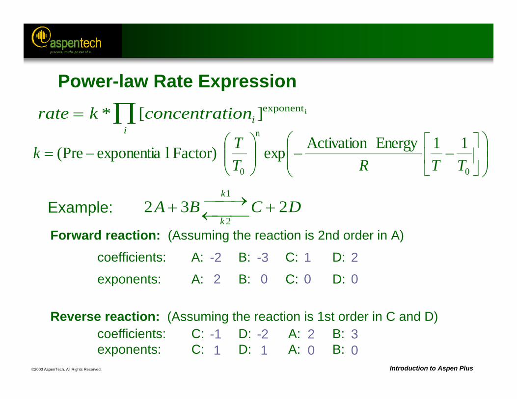
rate k concentrationii
* [ ]exponenti
Example: 2 3 21
2A B C D
k
k
Forward reaction: (Assuming the reaction is 2nd order in A)
coefficients: A: B: C: D:
exponents: A: B: C: D:
-2 -3 1 22 0 0 0
Reverse reaction: (Assuming the reaction is 1st order in C and D)coefficients: C: D: A: B: exponents: C: D: A: B:
-1 -2 2 31 1 0 0
©2000 AspenTech. All Rights Reserved. Introduction to Aspen Plus
Heats of Reaction
• Heats of reaction need not be provided for reactions.
• Heats of reaction are typically calculated as the difference between inlet and outlet enthalpies for the reactor (see Appendix A).
• If you have a heat of reaction value that does not match the value calculated by Aspen Plus, you can adjust the heats of formation (DHFORM) of one or more components to make the heats of reaction match.
• Heats of reaction can also be calculated or specified at a reference temperature and pressure in an RStoic reactor.
©2000 AspenTech. All Rights Reserved. Introduction to Aspen Plus
Reactor Workshop
• Objective - Compare the use of different reactor types to model one reaction.
• Reactor Conditions:Temperature = 70 CPressure = 1 atm
• Stoichiometry:Ethanol + Acetic Acid <--> Ethyl Acetate + Water
• Kinetic Parameters:– Forward Reaction: Pre-exp. Factor = 1.9 x 10⁸, Act. Energy = 5.95 x 10⁷ J/kmol– Reverse Reaction: Pre-exp. Factor = 5.0 x 10⁷, Act. Energy = 5.95 x 10⁷ J/kmol– Reactions are first order with respect to each of the reactants in the reaction (second
order overall).– Reactions occur in the liquid phase.– Composition basis is Molarity.
Hint: Check that each reactor is considering both Vapor and Liquid as Valid phases.
©2000 AspenTech. All Rights Reserved. Introduction to Aspen Plus
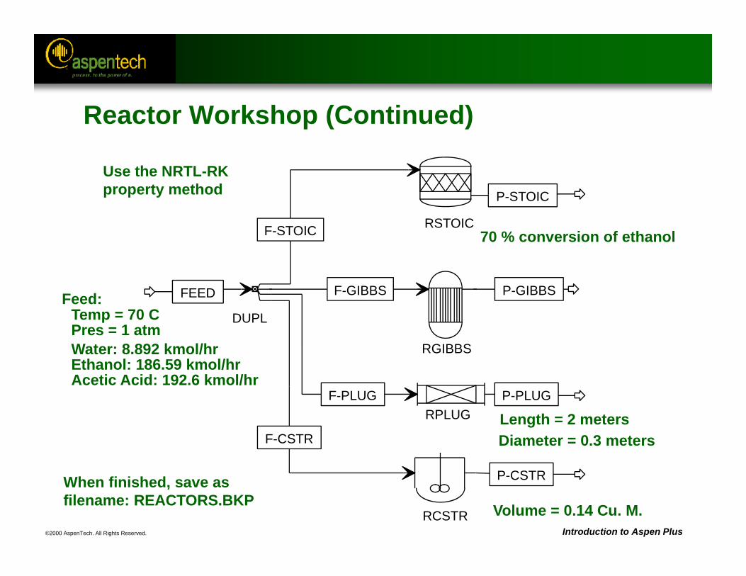
Temp = 70 CPres = 1 atm
Feed:
Water: 8.892 kmol/hrEthanol: 186.59 kmol/hrAcetic Acid: 192.6 kmol/hr
Length = 2 metersDiameter = 0.3 meters
Volume = 0.14 Cu. M.
70 % conversion of ethanol
When finished, save asfilename: REACTORS.BKP
Use the NRTL-RKproperty method
RSTOICF-STOIC
P-STOIC
RGIBBS
F-GIBBS P-GIBBS
RPLUGF-PLUG P-PLUG
DUPL
FEED
F-CSTR
RCSTR
P-CSTR
Reactor Workshop (Continued)
©2000 AspenTech. All Rights Reserved. Introduction to Aspen Plus
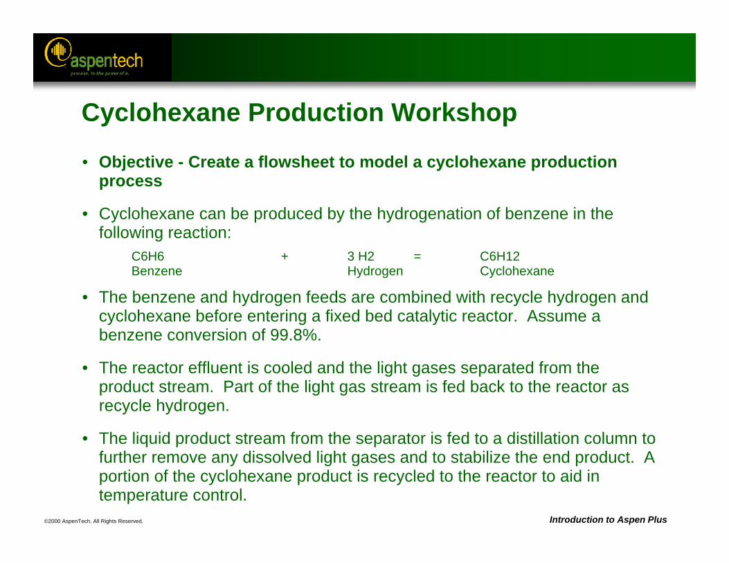
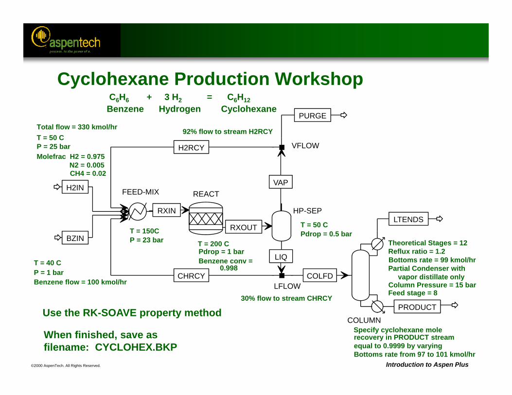
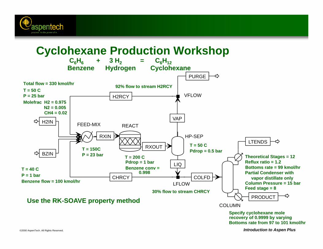
Cyclohexane Production Workshop
• Objective - Create a flowsheet to model a cyclohexane production process
• Cyclohexane can be produced by the hydrogenation of benzene in the following reaction:
C6H6 + 3 H2 = C6H12Benzene Hydrogen Cyclohexane
• The benzene and hydrogen feeds are combined with recycle hydrogen and cyclohexane before entering a fixed bed catalytic reactor. Assume a benzene conversion of 99.8%.
• The reactor effluent is cooled and the light gases separated from the product stream. Part of the light gas stream is fed back to the reactor as recycle hydrogen.
• The liquid product stream from the separator is fed to a distillation column to further remove any dissolved light gases and to stabilize the end product. A portion of the cyclohexane product is recycled to the reactor to aid in temperature control.
©2000 AspenTech. All Rights Reserved. Introduction to Aspen Plus
C6H6 + 3 H2 = C6H12Benzene Hydrogen Cyclohexane
Use the RK-SOAVE property method
When finished, save asfilename: CYCLOHEX.BKP
Bottoms rate = 99 kmol/hr
P = 25 barT = 50 C
Molefrac H2 = 0.975N2 = 0.005CH4 = 0.02
Total flow = 330 kmol/hr
T = 40 CP = 1 barBenzene flow = 100 kmol/hr
T = 150CP = 23 bar T = 200 C
Pdrop = 1 barBenzene conv =
0.998
T = 50 CPdrop = 0.5 bar
92% flow to stream H2RCY
30% flow to stream CHRCY
Specify cyclohexane molerecovery in PRODUCT streamequal to 0.9999 by varying Bottoms rate from 97 to 101 kmol/hr
Theoretical Stages = 12Reflux ratio = 1.2
Partial Condenser with vapor distillate only
Column Pressure = 15 barFeed stage = 8
REACTFEED-MIXH2IN
BZIN
H2RCY
CHRCY
RXIN
RXOUT
HP-SEP
VAP
COLUMN
COLFD
LTENDS
PRODUCT
VFLOW
PURGE
LFLOW
LIQ
Cyclohexane Production Workshop
©2000 AspenTech. All Rights Reserved.
Physical PropertiesObjectives:
Introduce the ideas of property methods and physical property parametersIdentify issues involved in the choice of a property method
Cover the use of Property Analysis for reporting physical properties
Aspen Plus References:User Guide, Chapter 7, Physical Property MethodsUser Guide, Chapter 8, Physical Property Parameters and DataUser Guide, Chapter 29, Analyzing Properties
©2000 AspenTech. All Rights Reserved. Introduction to Aspen Plus
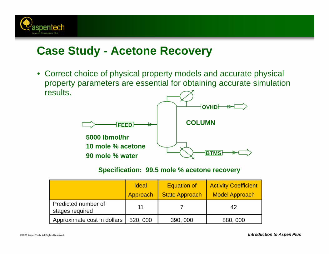
• Correct choice of physical property models and accurate physical property parameters are essential for obtaining accurate simulation results.
FEED
OVHD
BTMS
COLUMN
5000 lbmol/hr10 mole % acetone90 mole % water
Specification: 99.5 mole % acetone recovery
Case Study - Acetone Recovery
IdealApproach
Equation ofState Approach
Activity CoefficientModel Approach
Predicted number ofstages requiredApproximate cost in dollars
11
520, 000
7
390, 000
42
880, 000
©2000 AspenTech. All Rights Reserved. Introduction to Aspen Plus
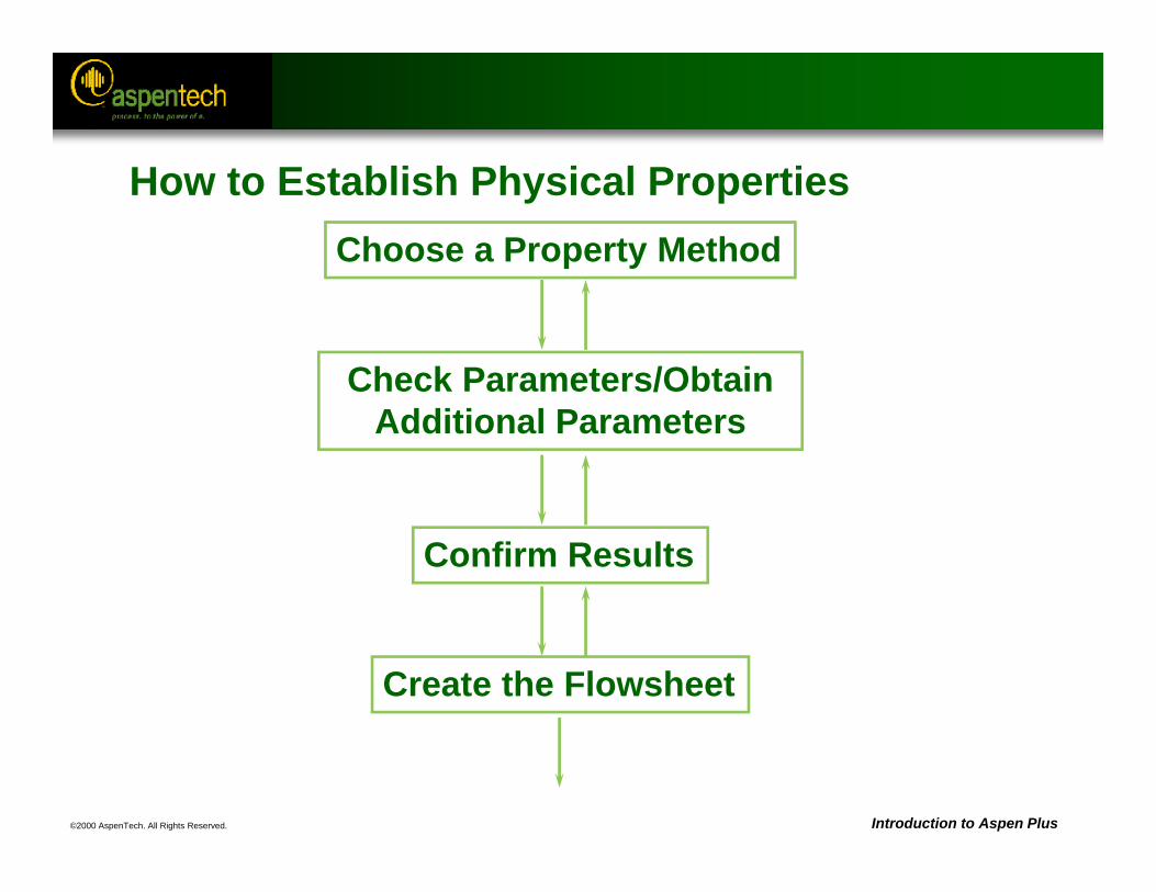
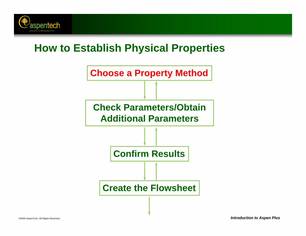
How to Establish Physical PropertiesChoose a Property Method
Check Parameters/Obtain Additional Parameters
Confirm Results
Create the Flowsheet
©2000 AspenTech. All Rights Reserved. Introduction to Aspen Plus
Property Methods
• A Property Method is a collection of models and methods used to calculate physical properties.
• Property Methods containing commonly used thermodynamic models are provided in Aspen Plus.
• Users can modify existing Property Methods or create new ones.
©2000 AspenTech. All Rights Reserved. Introduction to Aspen Plus
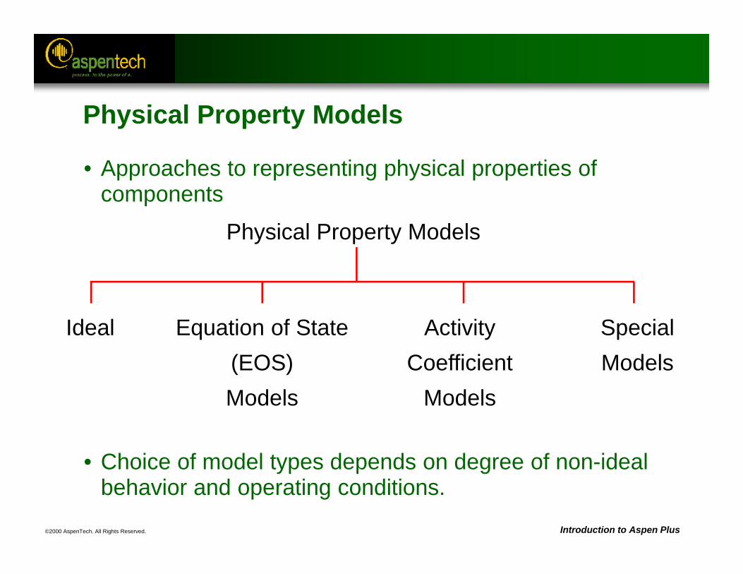
• Approaches to representing physical properties of components
• Choice of model types depends on degree of non-ideal behavior and operating conditions.
Physical Property Models
Ideal Equation of State(EOS)Models
ActivityCoefficient
Models
SpecialModels
Physical Property Models
©2000 AspenTech. All Rights Reserved. Introduction to Aspen Plus
x
y
x
y
x
y
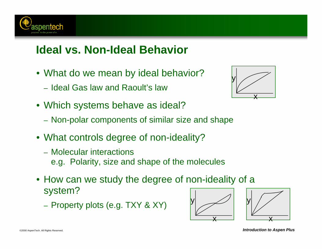
Ideal vs. Non-Ideal Behavior
• What do we mean by ideal behavior?– Ideal Gas law and Raoult’s law
• Which systems behave as ideal?– Non-polar components of similar size and shape
• What controls degree of non-ideality?– Molecular interactions
e.g. Polarity, size and shape of the molecules
• How can we study the degree of non-ideality of a system?– Property plots (e.g. TXY & XY)
©2000 AspenTech. All Rights Reserved. Introduction to Aspen Plus
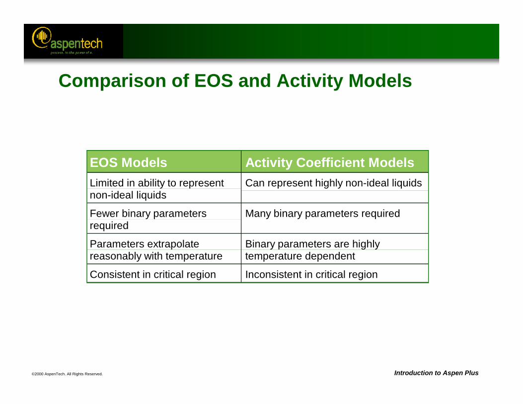
EOS Models Activity Coefficient ModelsLimited in ability to representnon-ideal liquids
Can represent highly non-ideal liquids
Fewer binary parametersrequired
Many binary parameters required
Parameters extrapolatereasonably with temperature
Binary parameters are highlytemperature dependent
Consistent in critical region Inconsistent in critical region
Comparison of EOS and Activity Models
©2000 AspenTech. All Rights Reserved. Introduction to Aspen Plus
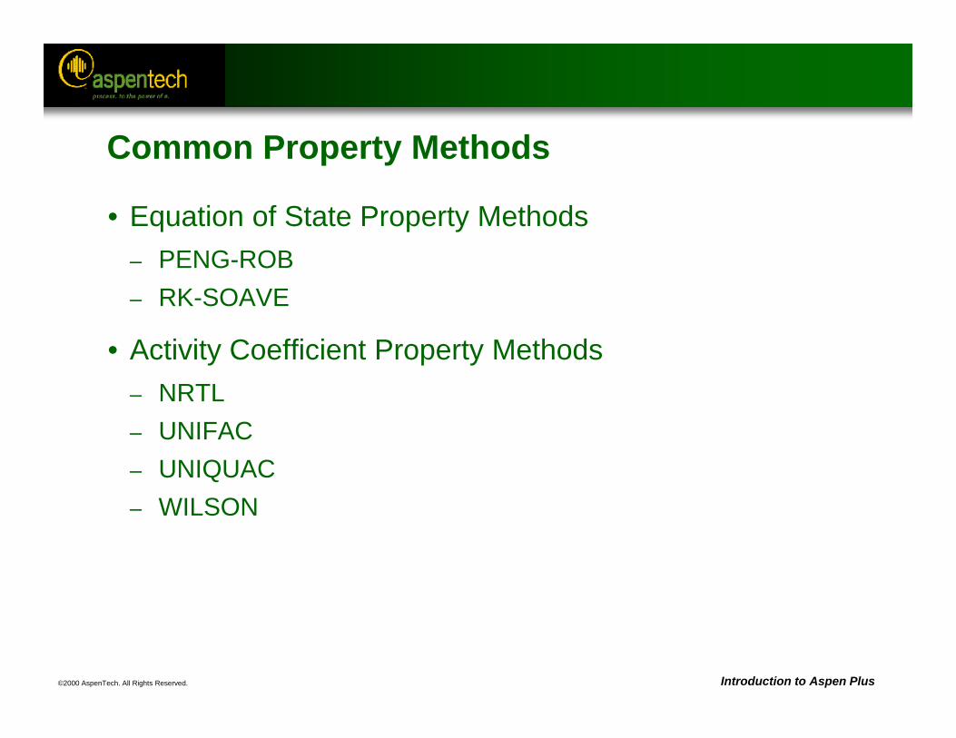
Common Property Methods
• Equation of State Property Methods– PENG-ROB– RK-SOAVE
• Activity Coefficient Property Methods– NRTL– UNIFAC– UNIQUAC– WILSON
©2000 AspenTech. All Rights Reserved. Introduction to Aspen Plus
Henry's Law
• Henry's Law is only used with ideal and activity coefficient models.
• It is used to determine the amount of a supercritical component or light gas in the liquid phase.
• Any supercritical components or light gases (CO2, N2, etc.) should be declared as Henry's components (Components Henry Comps Selection sheet).
• The Henry's components list ID should be entered on Properties Specifications Global sheet in the Henry Components field.
©2000 AspenTech. All Rights Reserved. Introduction to Aspen Plus
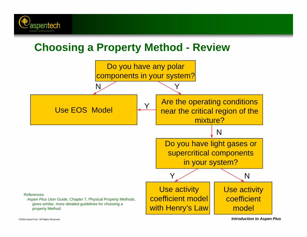
Do you have any polar components in your system?
Are the operating conditions near the critical region of the
mixture?
Use activitycoefficient model with Henry’s Law
Use activity coefficient
model
Use EOS Model
N
N
NY
Y
Y
References:Aspen Plus User Guide, Chapter 7, Physical Property Methods,
gives similar, more detailed guidelines for choosing a property Method.
Choosing a Property Method - Review
Do you have light gases orsupercritical components
in your system?
©2000 AspenTech. All Rights Reserved. Introduction to Aspen Plus
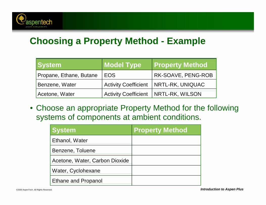
System Model Type Property MethodPropane, Ethane, Butane EOS RK-SOAVE, PENG-ROB
Benzene, Water Activity Coefficient NRTL-RK, UNIQUAC
Acetone, Water Activity Coefficient NRTL-RK, WILSON
System Property MethodEthanol, Water
Benzene, Toluene
Acetone, Water, Carbon Dioxide
Water, Cyclohexane
Ethane and Propanol
Choosing a Property Method - Example
• Choose an appropriate Property Method for the following systems of components at ambient conditions.
©2000 AspenTech. All Rights Reserved. Introduction to Aspen Plus
How to Establish Physical Properties
Choose a Property Method
Check Parameters/Obtain Additional Parameters
Confirm Results
Create the Flowsheet
©2000 AspenTech. All Rights Reserved. Introduction to Aspen Plus
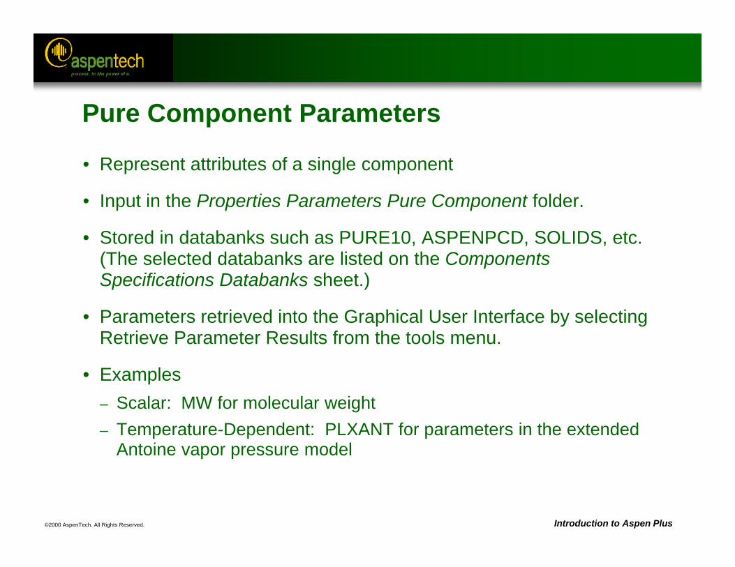
Pure Component Parameters
• Represent attributes of a single component
• Input in the Properties Parameters Pure Component folder.
• Stored in databanks such as PURE10, ASPENPCD, SOLIDS, etc. (The selected databanks are listed on the Components Specifications Databanks sheet.)
• Parameters retrieved into the Graphical User Interface by selecting Retrieve Parameter Results from the tools menu.
• Examples– Scalar: MW for molecular weight– Temperature-Dependent: PLXANT for parameters in the extended
Antoine vapor pressure model
©2000 AspenTech. All Rights Reserved. Introduction to Aspen Plus
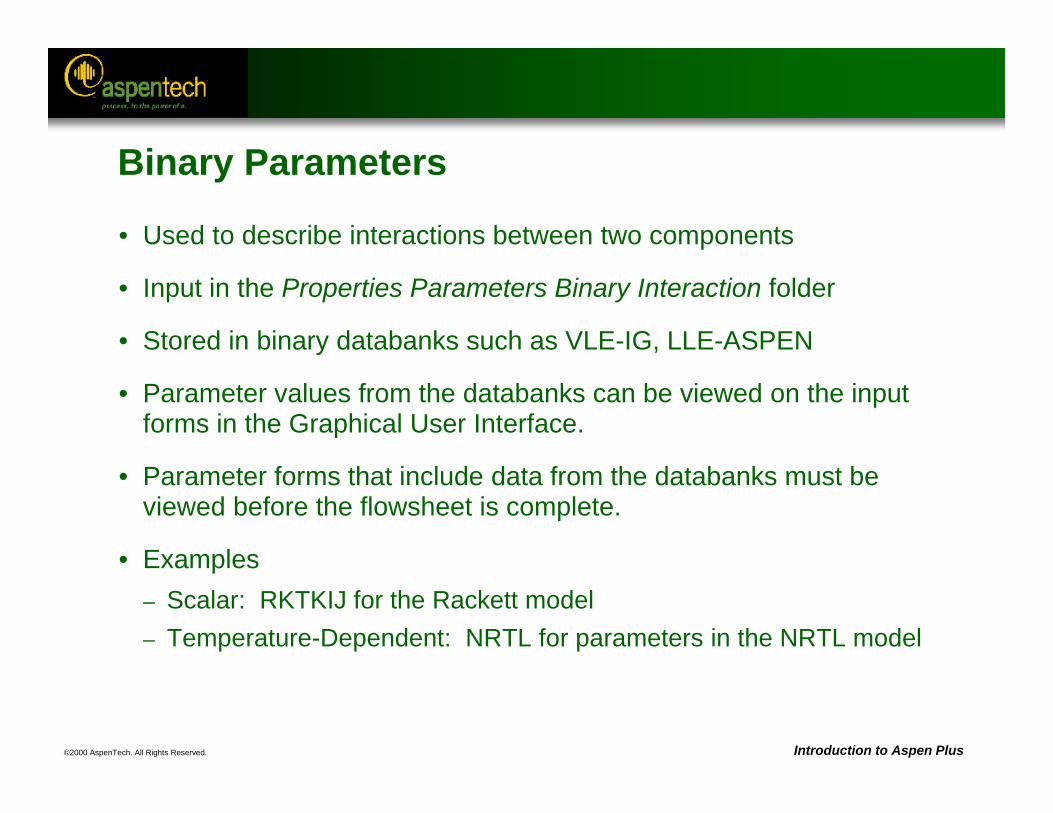
Binary Parameters
• Used to describe interactions between two components
• Input in the Properties Parameters Binary Interaction folder
• Stored in binary databanks such as VLE-IG, LLE-ASPEN
• Parameter values from the databanks can be viewed on the input forms in the Graphical User Interface.
• Parameter forms that include data from the databanks must be viewed before the flowsheet is complete.
• Examples– Scalar: RKTKIJ for the Rackett model – Temperature-Dependent: NRTL for parameters in the NRTL model
©2000 AspenTech. All Rights Reserved. Introduction to Aspen Plus
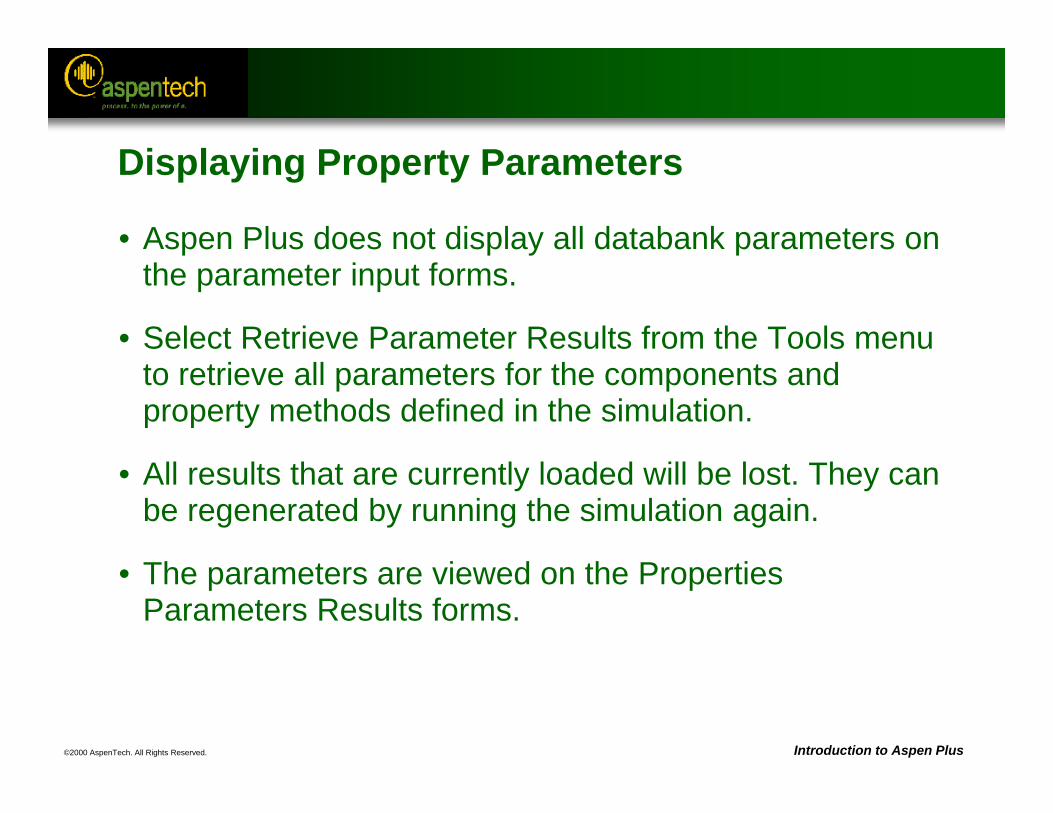
Displaying Property Parameters
• Aspen Plus does not display all databank parameters on the parameter input forms.
• Select Retrieve Parameter Results from the Tools menu to retrieve all parameters for the components and property methods defined in the simulation.
• All results that are currently loaded will be lost. They can be regenerated by running the simulation again.
• The parameters are viewed on the Properties Parameters Results forms.
©2000 AspenTech. All Rights Reserved. Introduction to Aspen Plus
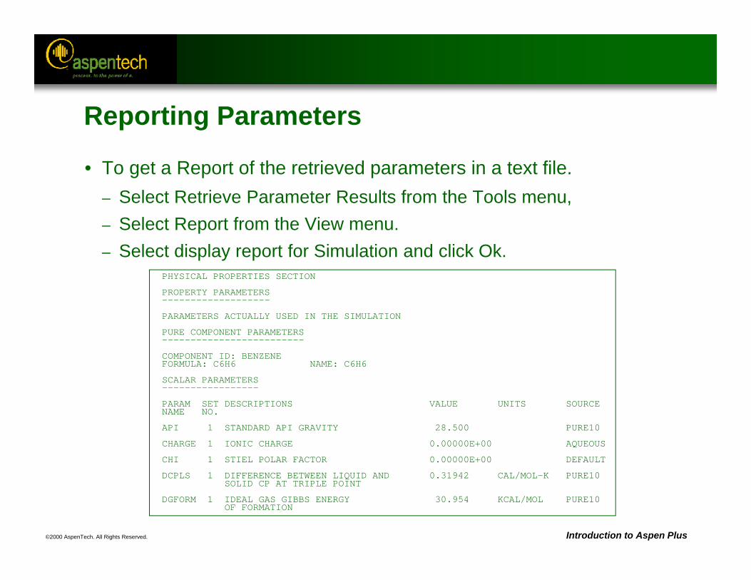
PHYSICAL PROPERTIES SECTION
PROPERTY PARAMETERS -------------------
PARAMETERS ACTUALLY USED IN THE SIMULATION
PURE COMPONENT PARAMETERS-------------------------
COMPONENT ID: BENZENE FORMULA: C6H6 NAME: C6H6
SCALAR PARAMETERS-----------------
PARAM SET DESCRIPTIONS VALUE UNITS SOURCENAME NO.
API 1 STANDARD API GRAVITY 28.500 PURE10
CHARGE 1 IONIC CHARGE 0.00000E+00 AQUEOUS
CHI 1 STIEL POLAR FACTOR 0.00000E+00 DEFAULT
DCPLS 1 DIFFERENCE BETWEEN LIQUID AND 0.31942 CAL/MOL-K PURE10 SOLID CP AT TRIPLE POINT
DGFORM 1 IDEAL GAS GIBBS ENERGY 30.954 KCAL/MOL PURE10 OF FORMATION
Reporting Parameters
• To get a Report of the retrieved parameters in a text file. – Select Retrieve Parameter Results from the Tools menu, – Select Report from the View menu.– Select display report for Simulation and click Ok.
©2000 AspenTech. All Rights Reserved. Introduction to Aspen Plus
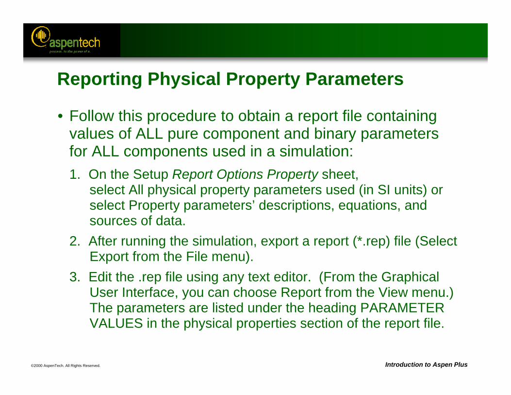
Reporting Physical Property Parameters
• Follow this procedure to obtain a report file containing values of ALL pure component and binary parameters for ALL components used in a simulation:1. On the Setup Report Options Property sheet,
select All physical property parameters used (in SI units) or select Property parameters’ descriptions, equations, and sources of data.
2. After running the simulation, export a report (*.rep) file (Select Export from the File menu).
3. Edit the .rep file using any text editor. (From the Graphical User Interface, you can choose Report from the View menu.) The parameters are listed under the heading PARAMETER VALUES in the physical properties section of the report file.
©2000 AspenTech. All Rights Reserved. Introduction to Aspen Plus
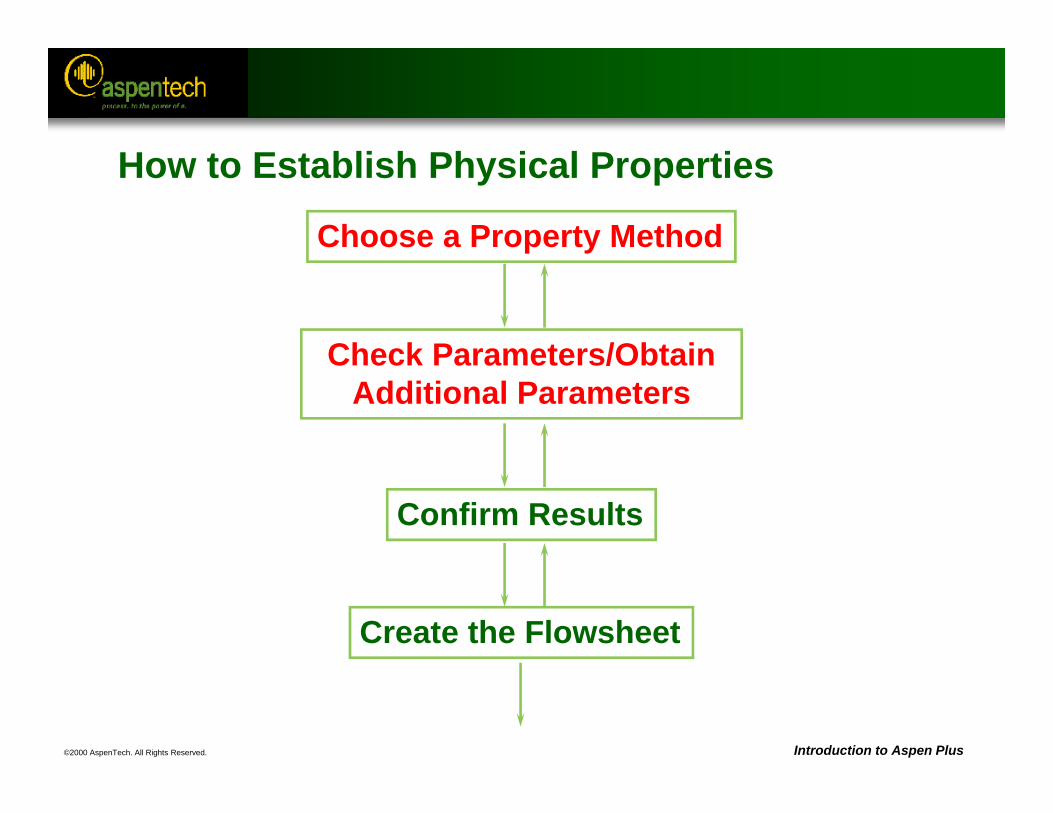
How to Establish Physical Properties
Choose a Property Method
Check Parameters/Obtain Additional Parameters
Confirm Results
Create the Flowsheet
©2000 AspenTech. All Rights Reserved. Introduction to Aspen Plus
Property Analysis
• Used to generate simple property diagrams to validate physical property models and data
• Diagram Types:– Pure component, e.g. Vapor pressure vs. temperature– Binary, e.g. TXY, PXY– Ternary residue maps
• Select Analysis from the Tools menu to start Analysis.
• Additional binary plots are available under the Plot Wizard button on result form containing raw data.
• When using a binary analysis to check for liquid-liquid phase separation, remember to choose Vapor-Liquid-Liquid as Valid phases.
• Property analysis input and results can be saved as a form for later reference and use.
©2000 AspenTech. All Rights Reserved. Introduction to Aspen Plus
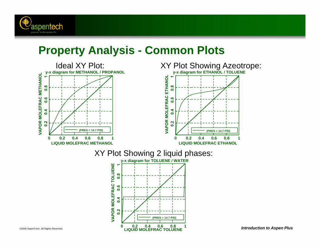
Property Analysis - Common Plotsy-x diagram for METHANOL / PROPANOL
LIQUID MOLEFRAC METHANOL0 0.2 0.4 0.6 0.8 1
(PRES = 14.7 PSI)
y-x diagram for ETHANOL / TOLUENE
LIQUID MOLEFRAC ETHANOL0 0.2 0.4 0.6 0.8 1
(PRES = 14.7 PSI)
y-x diagram for TOLUENE / WATER
LIQUID MOLEFRAC TOLUENE0 0.2 0.4 0.6 0.8 1
(PRES = 14.7 PSI)
XY Plot Showing 2 liquid phases:
Ideal XY Plot: XY Plot Showing Azeotrope:

©2000 AspenTech. All Rights Reserved. Introduction to Aspen Plus
How to Establish Physical Properties
Choose a Property Method
Check Parameters/Obtain Additional Parameters
Confirm Results
Create the Flowsheet
©2000 AspenTech. All Rights Reserved. Introduction to Aspen Plus
Establishing Physical Properties - Review
1. Choose Property Method - Select a Property Method based on– Components present in simulation– Operating conditions in simulation– Available data or parameters for the components
2. Check Parameters - Determine parameters available in Aspen Plus databanks
3. Obtain Additional Parameters (if necessary) - Parameters that are needed can be obtained from– Literature searches (DETHERM, etc.)– Regression of experimental data (Data Regression)– Property Constant Estimation (Property Estimation)
4. Confirm Results - Verify choice of Property Method and physical property data using– Physical Property Analysis
©2000 AspenTech. All Rights Reserved. Introduction to Aspen Plus
Property Sets
• A property set (Prop-Set) is a way of accessing a collection, or set, of properties as an object with a user-given name. Only the name of the property set is referenced when using the properties in an application.
• Use property sets to report thermodynamic, transport, and other property values.
• Current property set applications include:– Design specifications, Fortran blocks, sensitivity– Stream reports– Physical property tables (Property Analysis)– Tray properties (RadFrac, MultiFrac, etc.)– Heating/cooling curves (Flash2, MHeatX, etc.)
©2000 AspenTech. All Rights Reserved. Introduction to Aspen Plus
Properties included in Prop-Sets
• Properties commonly included in property sets include:– VFRAC - Molar vapor fraction of a stream– BETA - Fraction of liquid in a second liquid phase– CPMX - Constant pressure heat capacity for a mixture– MUMX - Viscosity for a mixture
• Available properties include:– Thermodynamic properties of components in a mixture– Pure component thermodynamic properties– Transport properties– Electrolyte properties– Petroleum-related properties
Reference: Aspen Plus Physical Property Data Reference Manual, Chapter 4, Property Sets, has a complete list of properties that can be included in a property set.
©2000 AspenTech. All Rights Reserved. Introduction to Aspen Plus
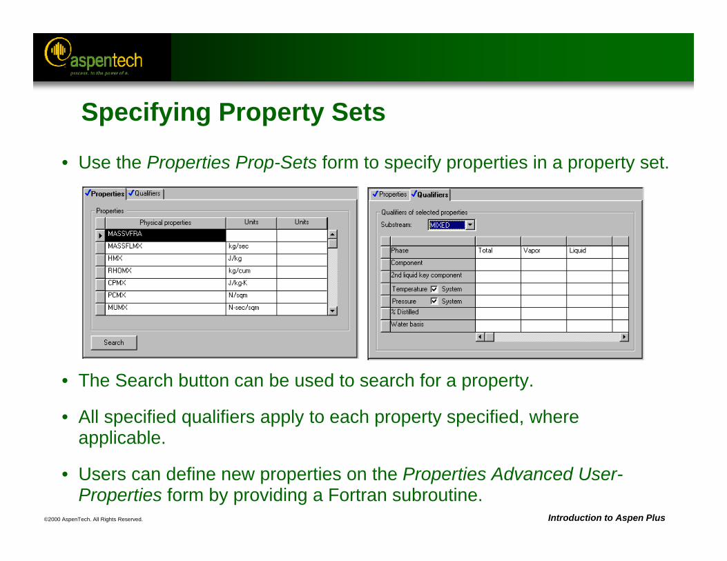
• Use the Properties Prop-Sets form to specify properties in a property set.
• The Search button can be used to search for a property.
• All specified qualifiers apply to each property specified, where applicable.
• Users can define new properties on the Properties Advanced User-Properties form by providing a Fortran subroutine.
Specifying Property Sets
©2000 AspenTech. All Rights Reserved. Introduction to Aspen Plus
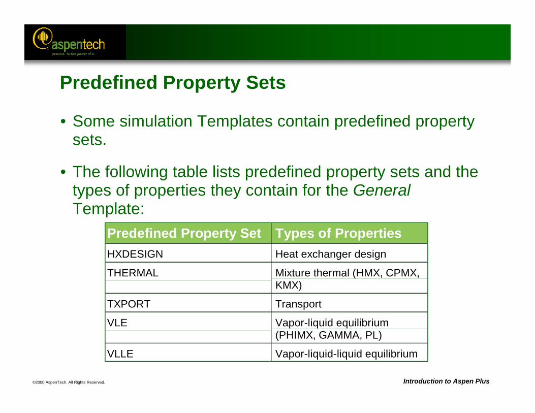
Predefined Property Set Types of PropertiesHXDESIGN Heat exchanger design
THERMAL Mixture thermal (HMX, CPMX,KMX)
TXPORT Transport
VLE Vapor-liquid equilibrium(PHIMX, GAMMA, PL)
VLLE Vapor-liquid-liquid equilibrium
Predefined Property Sets
• Some simulation Templates contain predefined property sets.
• The following table lists predefined property sets and the types of properties they contain for the GeneralTemplate:
©2000 AspenTech. All Rights Reserved. Introduction to Aspen Plus
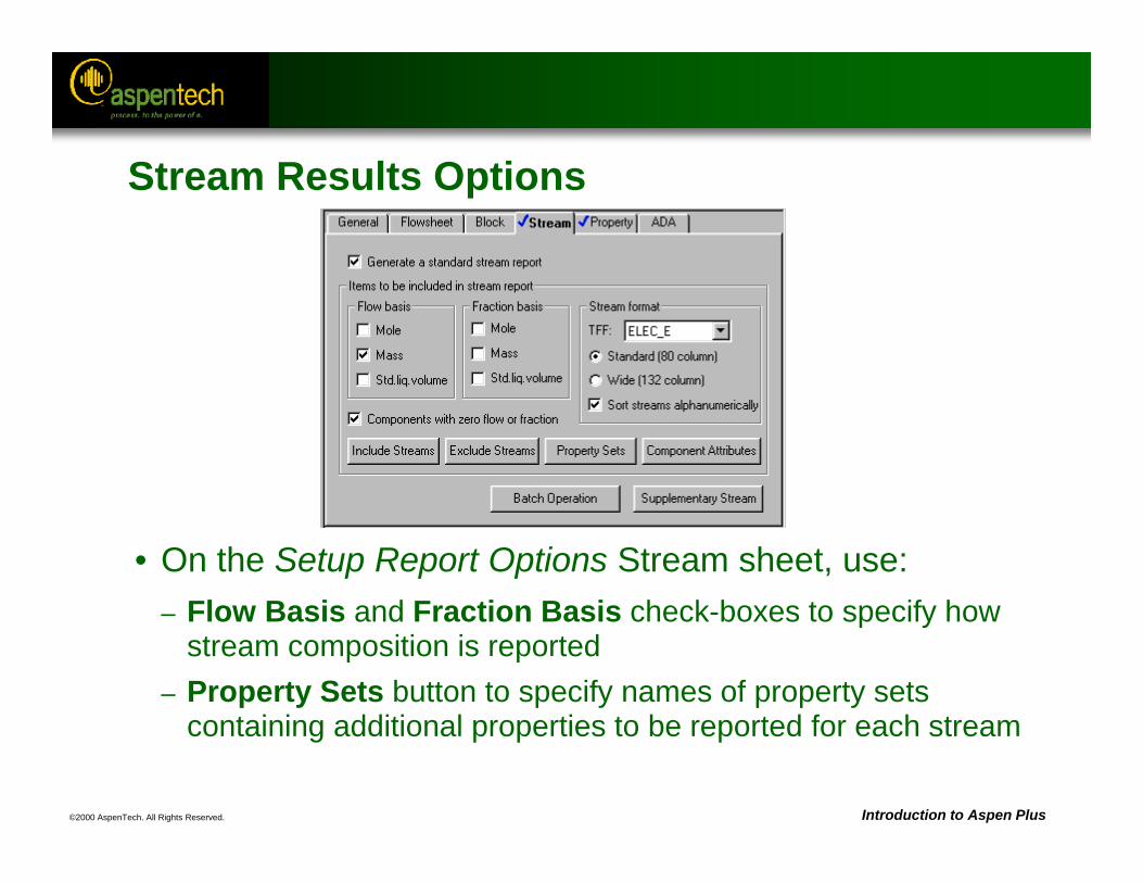
Stream Results Options
• On the Setup Report Options Stream sheet, use: – Flow Basis and Fraction Basis check-boxes to specify how
stream composition is reported– Property Sets button to specify names of property sets
containing additional properties to be reported for each stream
©2000 AspenTech. All Rights Reserved. Introduction to Aspen Plus
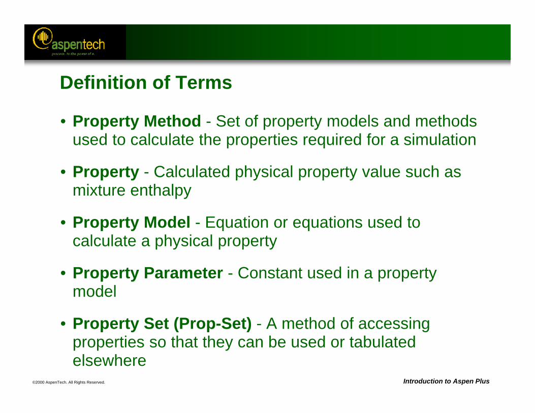
Definition of Terms
• Property Method - Set of property models and methods used to calculate the properties required for a simulation
• Property - Calculated physical property value such as mixture enthalpy
• Property Model - Equation or equations used to calculate a physical property
• Property Parameter - Constant used in a property model
• Property Set (Prop-Set) - A method of accessing properties so that they can be used or tabulated elsewhere
©2000 AspenTech. All Rights Reserved. Introduction to Aspen Plus
Aspen Properties
• Aspen Properties is now a stand-alone product.
• In addition to the standard property features available in Aspen Plus, Aspen Properties includes:– Excel Interface – Web Interface
• Excel Interface is an Excel Add-In that has Excel functions to do property calculations such as:– Flash at a given set of conditions– Calculate a property such as density or viscosity
• Web Interface is currently only available for pure components.
©2000 AspenTech. All Rights Reserved. Introduction to Aspen Plus
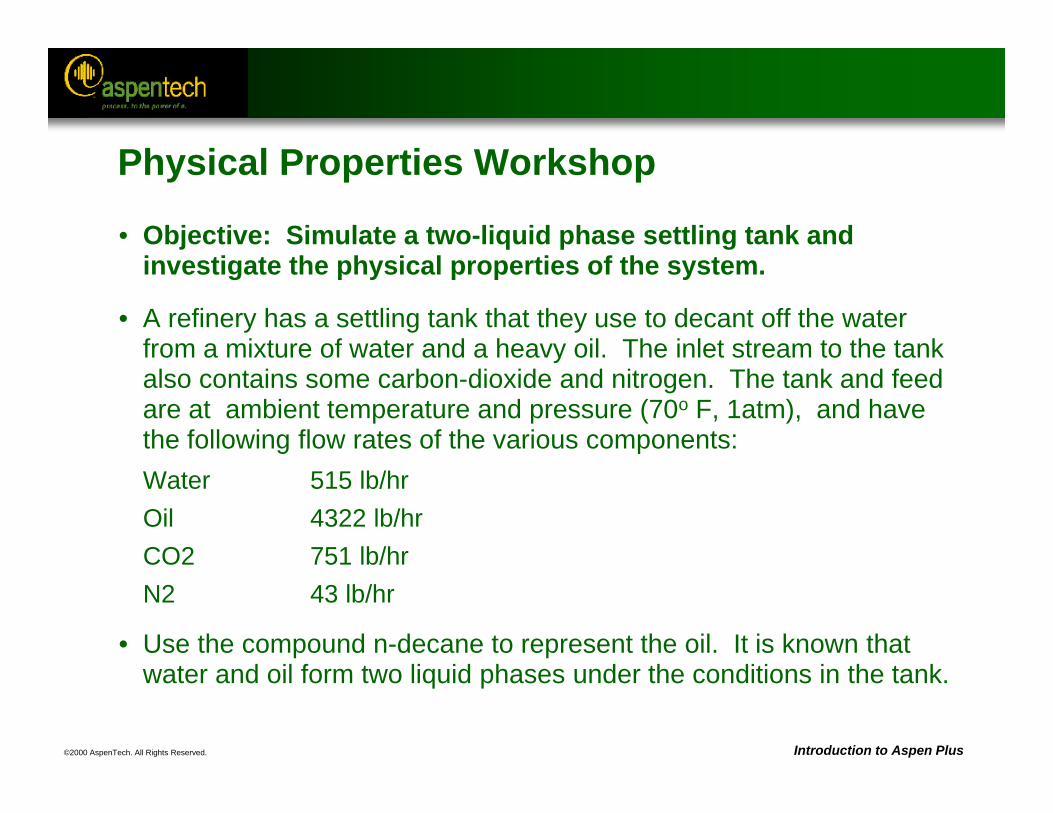
Physical Properties Workshop
• Objective: Simulate a two-liquid phase settling tank and investigate the physical properties of the system.
• A refinery has a settling tank that they use to decant off the water from a mixture of water and a heavy oil. The inlet stream to the tank also contains some carbon-dioxide and nitrogen. The tank and feed are at ambient temperature and pressure (70o F, 1atm), and have the following flow rates of the various components:Water 515 lb/hrOil 4322 lb/hrCO2 751 lb/hrN2 43 lb/hr
• Use the compound n-decane to represent the oil. It is known that water and oil form two liquid phases under the conditions in the tank.
©2000 AspenTech. All Rights Reserved. Introduction to Aspen Plus
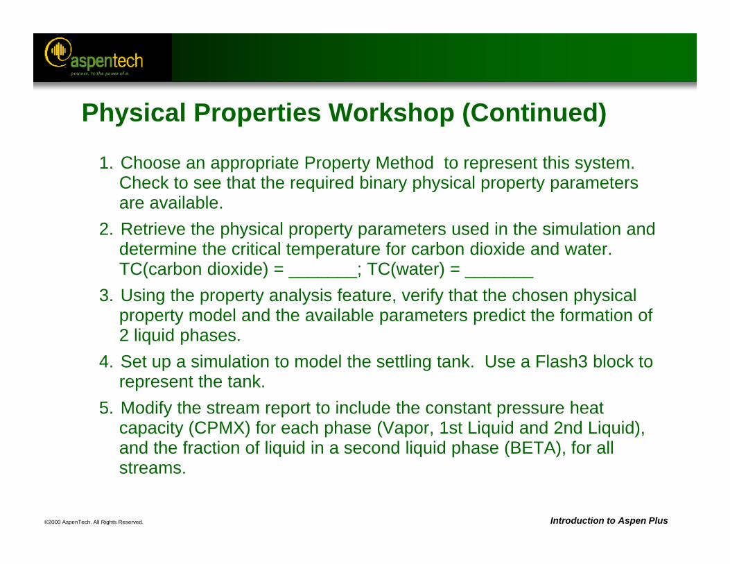
Physical Properties Workshop (Continued)
1. Choose an appropriate Property Method to represent this system. Check to see that the required binary physical property parameters are available.
2. Retrieve the physical property parameters used in the simulation and determine the critical temperature for carbon dioxide and water.TC(carbon dioxide) = _______; TC(water) = _______
3. Using the property analysis feature, verify that the chosen physical property model and the available parameters predict the formation of 2 liquid phases.
4. Set up a simulation to model the settling tank. Use a Flash3 block to represent the tank.
5. Modify the stream report to include the constant pressure heat capacity (CPMX) for each phase (Vapor, 1st Liquid and 2nd Liquid), and the fraction of liquid in a second liquid phase (BETA), for all streams.
©2000 AspenTech. All Rights Reserved. Introduction to Aspen Plus
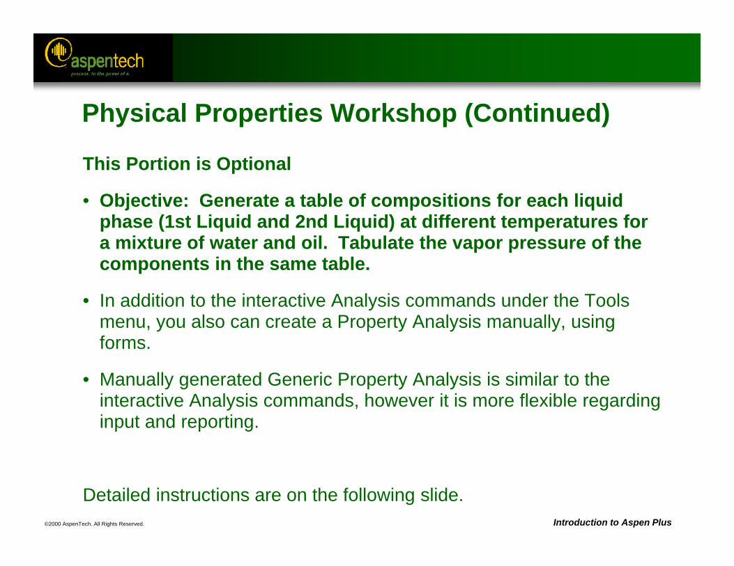
Physical Properties Workshop (Continued)
This Portion is Optional
• Objective: Generate a table of compositions for each liquid phase (1st Liquid and 2nd Liquid) at different temperatures for a mixture of water and oil. Tabulate the vapor pressure of the components in the same table.
• In addition to the interactive Analysis commands under the Tools menu, you also can create a Property Analysis manually, using forms.
• Manually generated Generic Property Analysis is similar to the interactive Analysis commands, however it is more flexible regarding input and reporting.
Detailed instructions are on the following slide.
©2000 AspenTech. All Rights Reserved. Introduction to Aspen Plus
Physical Properties Workshop (Continued)
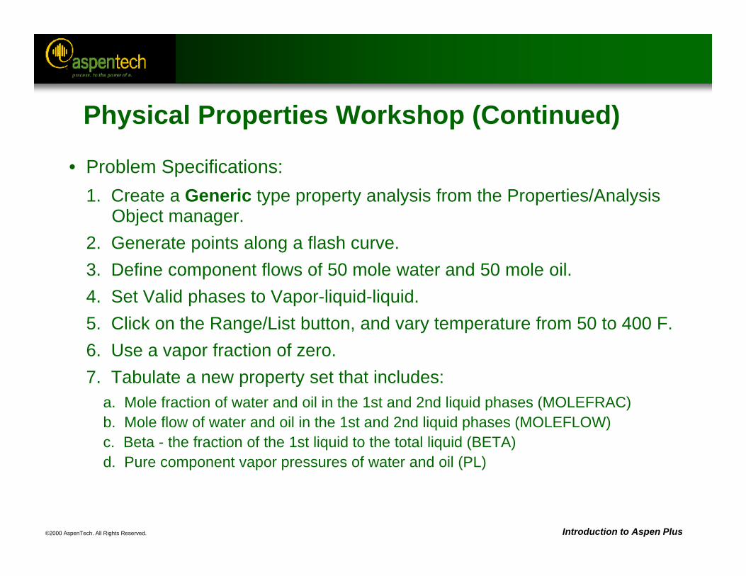
• Problem Specifications:1. Create a Generic type property analysis from the Properties/Analysis
Object manager.2. Generate points along a flash curve.3. Define component flows of 50 mole water and 50 mole oil.4. Set Valid phases to Vapor-liquid-liquid.5. Click on the Range/List button, and vary temperature from 50 to 400 F.6. Use a vapor fraction of zero.7. Tabulate a new property set that includes:
a. Mole fraction of water and oil in the 1st and 2nd liquid phases (MOLEFRAC)b. Mole flow of water and oil in the 1st and 2nd liquid phases (MOLEFLOW)c. Beta - the fraction of the 1st liquid to the total liquid (BETA)d. Pure component vapor pressures of water and oil (PL)
©2000 AspenTech. All Rights Reserved.
Accessing Variables
Objective:Become familiar with referencing flowsheet
variables
Aspen Plus References:User Guide, Chapter 18, Accessing Flowsheet Variables
Related Topics:User Guide, Chapter 20, SensitivityUser Guide, Chapter 21, Design SpecificationsUser Guide, Chapter 19, Calculator Blocks and In-Line FortranUser Guide, Chapter 22, Optimization User Guide, Chapter 23, Fitting a Simulation Model to Data
©2000 AspenTech. All Rights Reserved. Introduction to Aspen Plus
COLUMNFEED
OVHD
BTMS
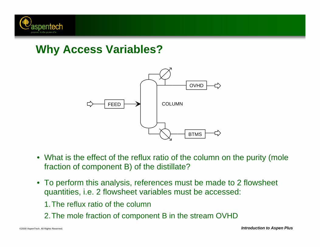
Why Access Variables?
• What is the effect of the reflux ratio of the column on the purity (mole fraction of component B) of the distillate?
• To perform this analysis, references must be made to 2 flowsheet quantities, i.e. 2 flowsheet variables must be accessed:1.The reflux ratio of the column2.The mole fraction of component B in the stream OVHD
©2000 AspenTech. All Rights Reserved. Introduction to Aspen Plus
Accessing Variables
• An accessed variable is a reference to a particular flowsheet quantity, e.g. temperature of a stream or duty of a block.
• Accessed variables can be input, results, or both.
• Flowsheet result variables (calculated quantities) should not be overwritten or varied.
• The concept of accessing variables is used in sensitivity analyses, design specifications, calculator blocks, optimization, etc.
©2000 AspenTech. All Rights Reserved. Introduction to Aspen Plus
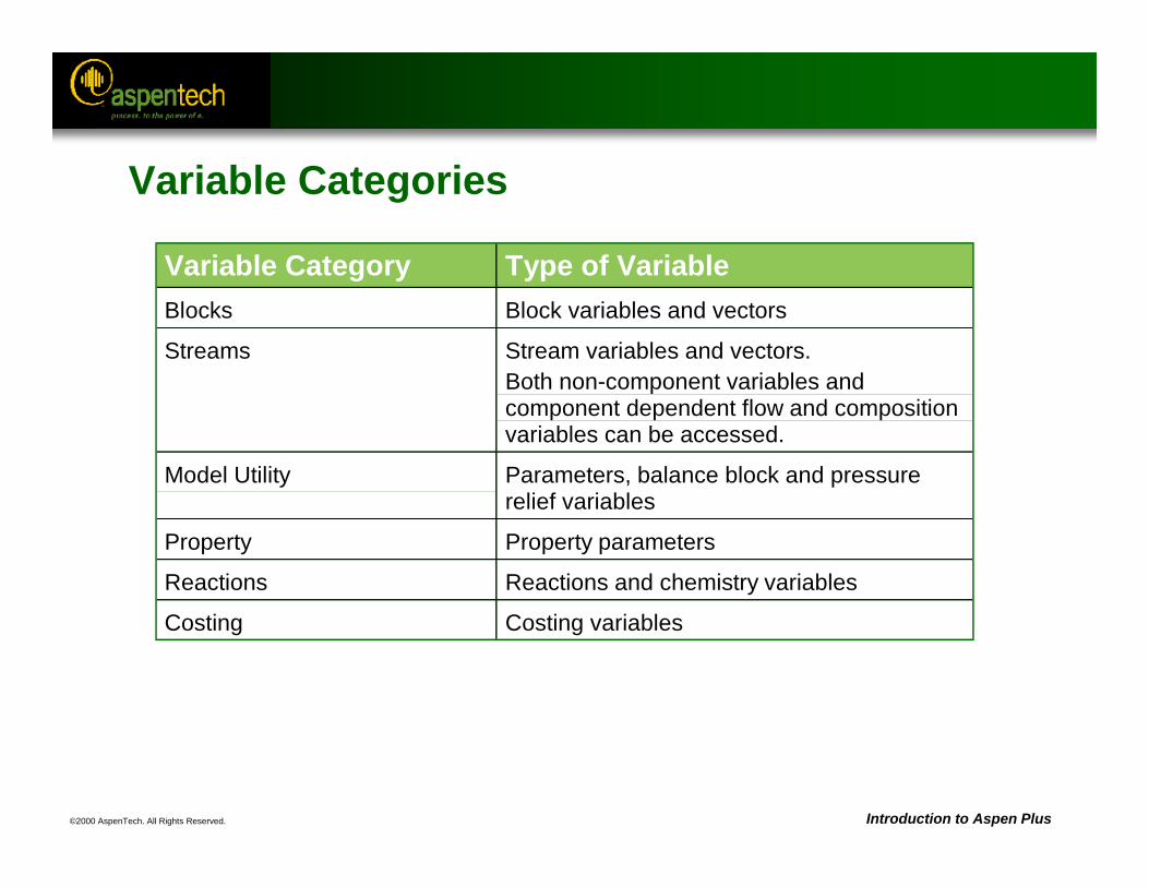
Variable Categories
Variable Category Type of Variable Blocks Block variables and vectors
Streams Stream variables and vectors.Both non-component variables andcomponent dependent flow and compositionvariables can be accessed.
Model Utility Parameters, balance block and pressurerelief variables
Property Property parameters
Reactions Reactions and chemistry variables
Costing Costing variables
©2000 AspenTech. All Rights Reserved. Introduction to Aspen Plus
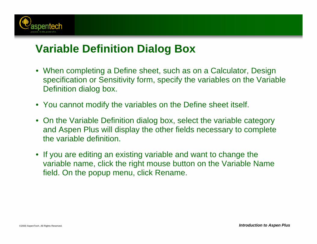
Variable Definition Dialog Box
• When completing a Define sheet, such as on a Calculator, Design specification or Sensitivity form, specify the variables on the Variable Definition dialog box.
• You cannot modify the variables on the Define sheet itself.
• On the Variable Definition dialog box, select the variable category and Aspen Plus will display the other fields necessary to complete the variable definition.
• If you are editing an existing variable and want to change the variable name, click the right mouse button on the Variable Name field. On the popup menu, click Rename.
©2000 AspenTech. All Rights Reserved. Introduction to Aspen Plus
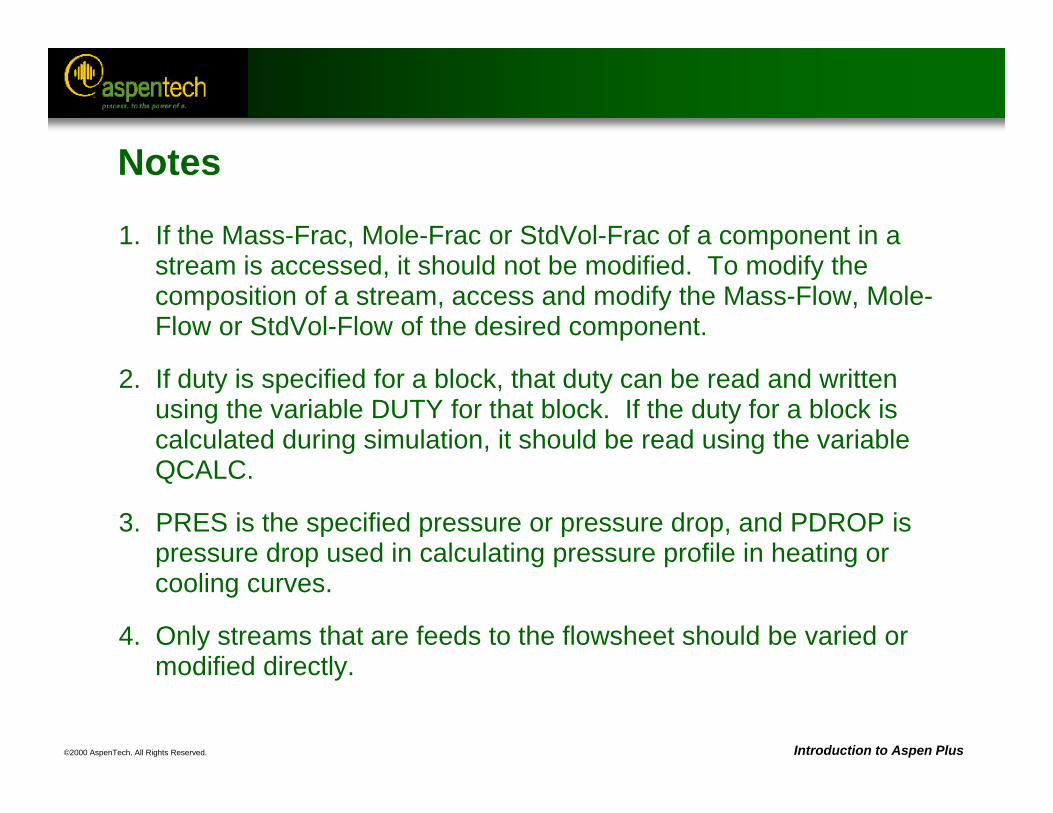
Notes
1. If the Mass-Frac, Mole-Frac or StdVol-Frac of a component in a stream is accessed, it should not be modified. To modify the composition of a stream, access and modify the Mass-Flow, Mole-Flow or StdVol-Flow of the desired component.
2. If duty is specified for a block, that duty can be read and written using the variable DUTY for that block. If the duty for a block is calculated during simulation, it should be read using the variable QCALC.
3. PRES is the specified pressure or pressure drop, and PDROP is pressure drop used in calculating pressure profile in heating or cooling curves.
4. Only streams that are feeds to the flowsheet should be varied or modified directly.
©2000 AspenTech. All Rights Reserved.
Sensitivity Analysis
Objective:Introduce the use of sensitivity analysis to study
relationships between process variables
Aspen Plus References:User Guide, Chapter 20, Sensitivity
Related Topics:User Guide, Chapter 18, Accessing Flowsheet VariablesUser Guide, Chapter 19, Calculator Blocks and In-Line Fortran
©2000 AspenTech. All Rights Reserved. Introduction to Aspen Plus
Sensitivity Analysis
• Allows user to study the effect of changes in input variables on process outputs.
• Results can be viewed by looking at the Results form in the folder for the Sensitivity block.
• Results may be graphed to easily visualize relationships between different variables.
• Changes made to a flowsheet input quantity in a sensitivity block do not affect the simulation. The sensitivity study is run independently of the base-case simulation.
• Located under /Data/Model Analysis Tools/Sensitivity
©2000 AspenTech. All Rights Reserved. Introduction to Aspen Plus
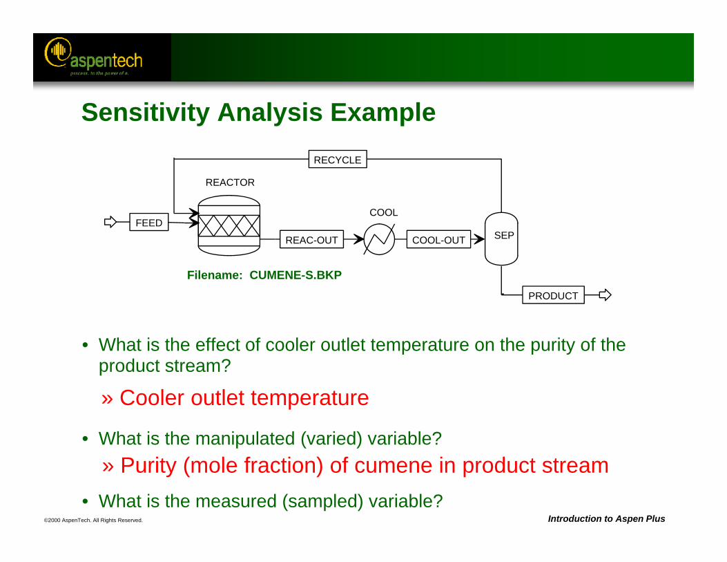
• What is the effect of cooler outlet temperature on the purity of the product stream?
• What is the manipulated (varied) variable?
• What is the measured (sampled) variable?
Filename: CUMENE-S.BKP
» Cooler outlet temperature
» Purity (mole fraction) of cumene in product stream
REACTOR
FEED
RECYCLE
REAC-OUT
COOL
COOL-OUT SEP
PRODUCT
Sensitivity Analysis Example
©2000 AspenTech. All Rights Reserved. Introduction to Aspen Plus
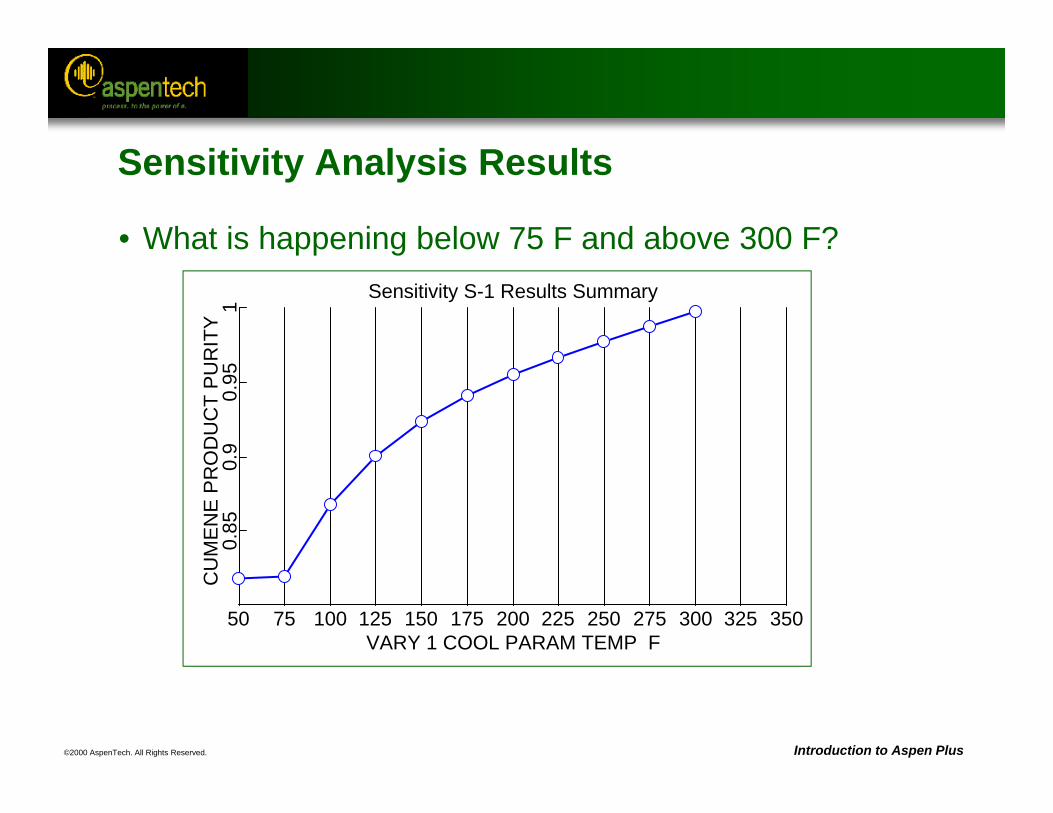
Sensitivity S-1 Results Summary
VARY 1 COOL PARAM TEMP F50 75 100 125 150 175 200 225 250 275 300 325 350
CU
ME
NE
PR
OD
UC
T P
UR
ITY
0.85
0.9
0.95
1
Sensitivity Analysis Results
• What is happening below 75 F and above 300 F?
©2000 AspenTech. All Rights Reserved. Introduction to Aspen Plus
Uses of Sensitivity Analysis
• Studying the effect of changes in input variables on process (model) outputs
• Graphically representing the effects of input variables
• Verifying that a solution to a design specification is feasible
• Rudimentary optimization
• Studying time varying variables using a quasi-steady-state approach
©2000 AspenTech. All Rights Reserved. Introduction to Aspen Plus
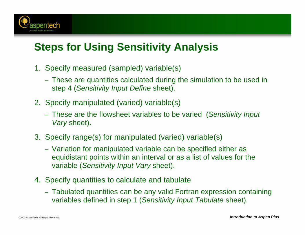
Steps for Using Sensitivity Analysis
1. Specify measured (sampled) variable(s)– These are quantities calculated during the simulation to be used in
step 4 (Sensitivity Input Define sheet).
2. Specify manipulated (varied) variable(s)– These are the flowsheet variables to be varied (Sensitivity Input
Vary sheet).
3. Specify range(s) for manipulated (varied) variable(s)– Variation for manipulated variable can be specified either as
equidistant points within an interval or as a list of values for the variable (Sensitivity Input Vary sheet).
4. Specify quantities to calculate and tabulate– Tabulated quantities can be any valid Fortran expression containing
variables defined in step 1 (Sensitivity Input Tabulate sheet).
©2000 AspenTech. All Rights Reserved. Introduction to Aspen Plus
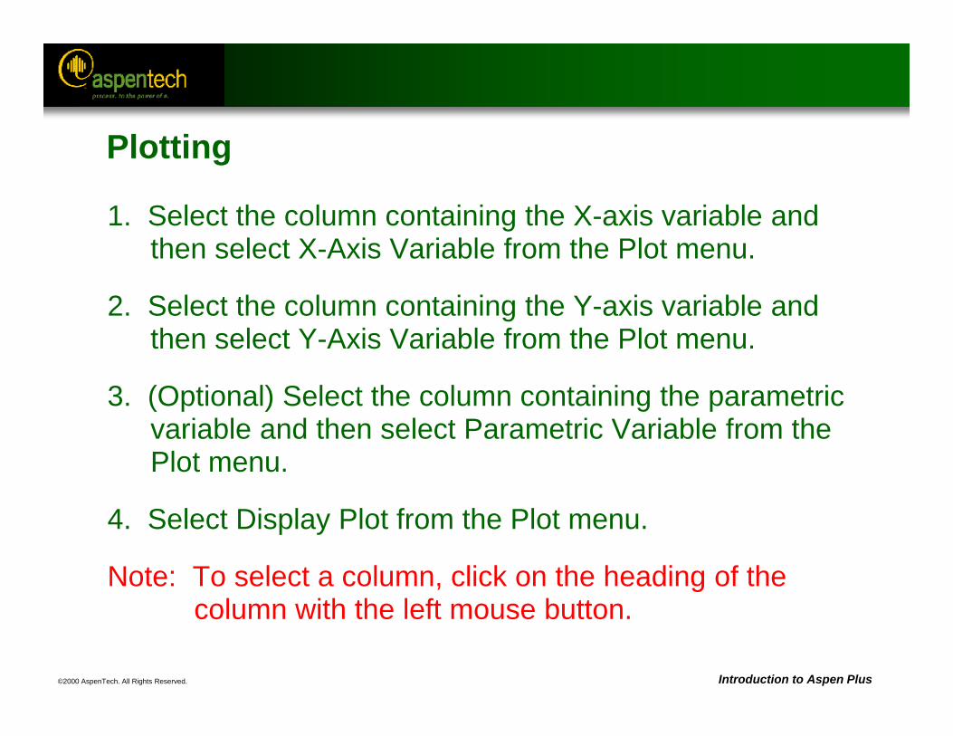
Plotting
1. Select the column containing the X-axis variable and then select X-Axis Variable from the Plot menu.
2. Select the column containing the Y-axis variable and then select Y-Axis Variable from the Plot menu.
3. (Optional) Select the column containing the parametric variable and then select Parametric Variable from the Plot menu.
4. Select Display Plot from the Plot menu.
Note: To select a column, click on the heading of the column with the left mouse button.
©2000 AspenTech. All Rights Reserved. Introduction to Aspen Plus
Notes
1. Only quantities that have been input to the flowsheet should be varied or manipulated.
2. Multiple inputs can be varied.
3. The simulation is run for every combination of manipulated (varied) variables.
©2000 AspenTech. All Rights Reserved. Introduction to Aspen Plus
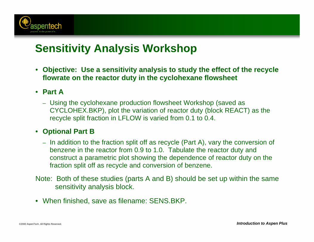
Sensitivity Analysis Workshop
• Objective: Use a sensitivity analysis to study the effect of the recycle flowrate on the reactor duty in the cyclohexane flowsheet
• Part A– Using the cyclohexane production flowsheet Workshop (saved as
CYCLOHEX.BKP), plot the variation of reactor duty (block REACT) as the recycle split fraction in LFLOW is varied from 0.1 to 0.4.
• Optional Part B– In addition to the fraction split off as recycle (Part A), vary the conversion of
benzene in the reactor from 0.9 to 1.0. Tabulate the reactor duty and construct a parametric plot showing the dependence of reactor duty on the fraction split off as recycle and conversion of benzene.
Note: Both of these studies (parts A and B) should be set up within the same sensitivity analysis block.
• When finished, save as filename: SENS.BKP.
©2000 AspenTech. All Rights Reserved. Introduction to Aspen Plus
Cyclohexane Production WorkshopC6H6 + 3 H2 = C6H12
Benzene Hydrogen Cyclohexane
Use the RK-SOAVE property method
Bottoms rate = 99 kmol/hr
P = 25 barT = 50 C
Molefrac H2 = 0.975N2 = 0.005CH4 = 0.02
Total flow = 330 kmol/hr
T = 40 CP = 1 barBenzene flow = 100 kmol/hr
T = 150CP = 23 bar T = 200 C
Pdrop = 1 barBenzene conv =
0.998
T = 50 CPdrop = 0.5 bar
92% flow to stream H2RCY
30% flow to stream CHRCY
Specify cyclohexane molerecovery of 0.9999 by varyingBottoms rate from 97 to 101 kmol/hr
Theoretical Stages = 12Reflux ratio = 1.2
Partial Condenser with vapor distillate only
Column Pressure = 15 barFeed stage = 8
REACTFEED-MIXH2IN
BZIN
H2RCY
CHRCY
RXIN
RXOUT
HP-SEP
VAP
COLUMN
COLFD
LTENDS
PRODUCT
VFLOW
PURGE
LFLOW
LIQ
©2000 AspenTech. All Rights Reserved.
Design Specifications
Objective:Introduce the use of design specifications to meet
process design requirements
Aspen Plus ReferencesUser Guide, Chapter 21, Design Specifications
Related TopicsUser Guide, Chapter 18, Accessing Flowsheet VariablesUser Guide, Chapter 19, Calculator Blocks and In-Line FortranUser Guide, Chapter 17, Convergence
©2000 AspenTech. All Rights Reserved. Introduction to Aspen Plus
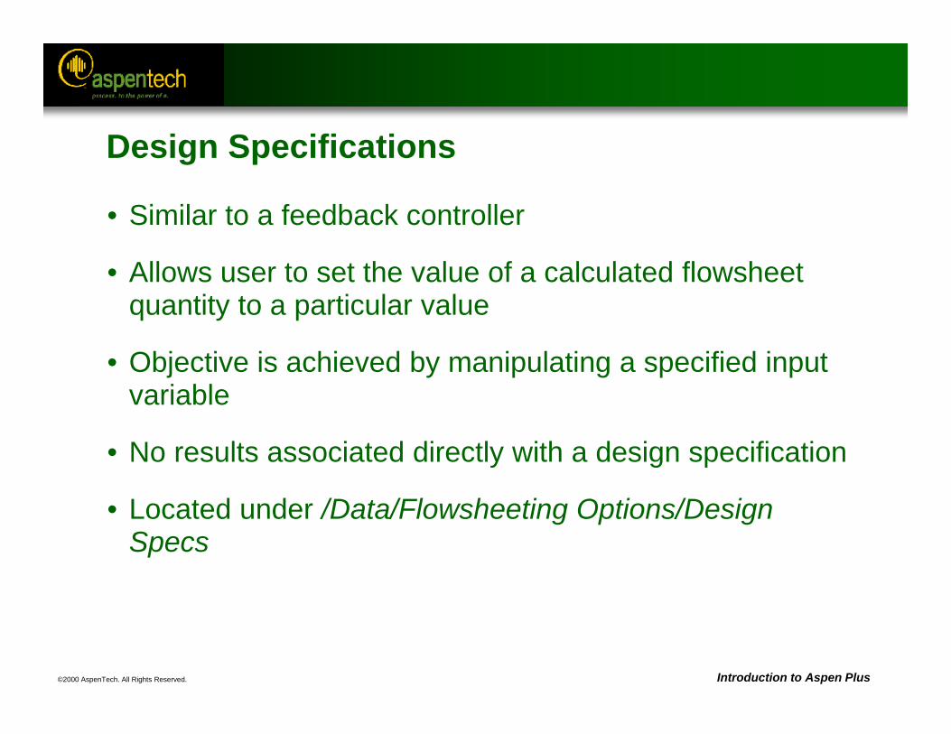
Design Specifications
• Similar to a feedback controller
• Allows user to set the value of a calculated flowsheet quantity to a particular value
• Objective is achieved by manipulating a specified input variable
• No results associated directly with a design specification
• Located under /Data/Flowsheeting Options/Design Specs
©2000 AspenTech. All Rights Reserved. Introduction to Aspen Plus
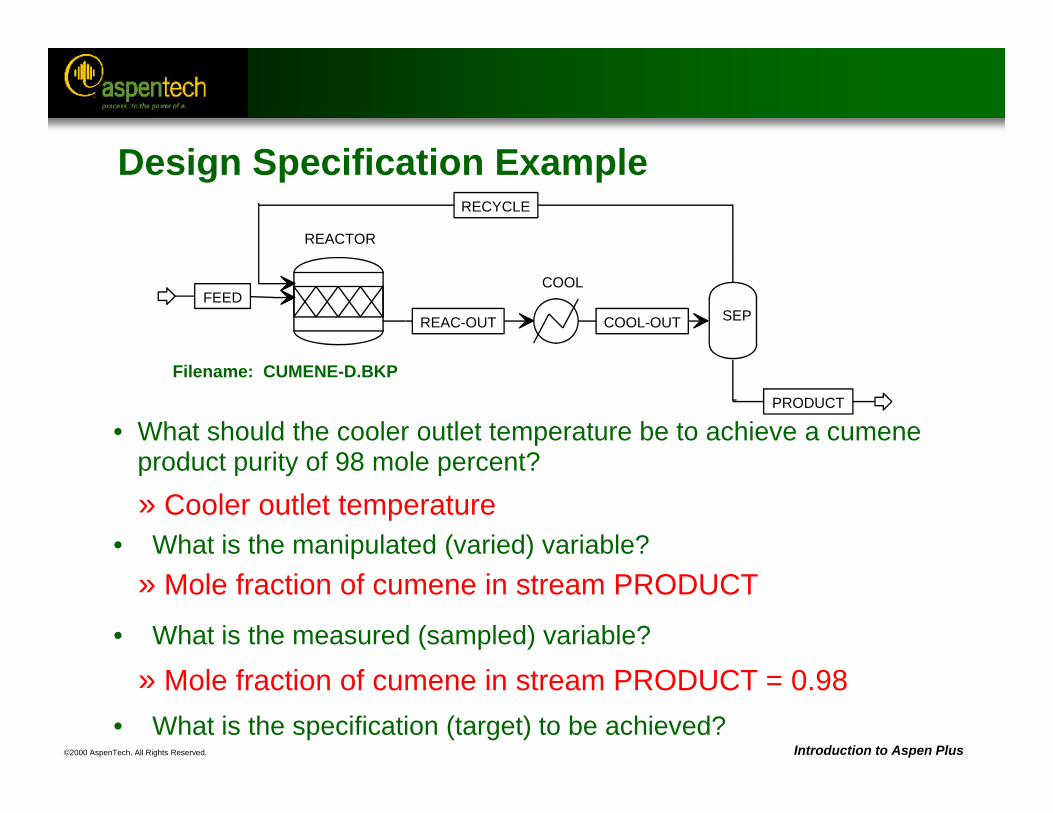
• What should the cooler outlet temperature be to achieve a cumene product purity of 98 mole percent?
• What is the manipulated (varied) variable?
• What is the measured (sampled) variable?
• What is the specification (target) to be achieved?
Filename: CUMENE-D.BKP
» Cooler outlet temperature
» Mole fraction of cumene in stream PRODUCT
» Mole fraction of cumene in stream PRODUCT = 0.98
REACTOR
FEED
RECYCLE
REAC-OUT
COOL
COOL-OUT SEP
PRODUCT
Design Specification Example
©2000 AspenTech. All Rights Reserved. Introduction to Aspen Plus
Steps for Using Design Specifications
1. Identify measured (sampled) variables– These are flowsheet quantities, usually calculated quantities, to be
included in the objective function (Design Spec Define sheet).
2. Specify objective function (Spec) and goal (Target)– This is the equation that the specification attempts to satisfy
(Design Spec Spec sheet). The units of the variable used in the objective function are the units for that type of variable as specified by the Units Set declared for the design specification.
3. Set tolerance for objective function– The specification is said to be converged if the objective function
equation is satisfied to within this tolerance (Design Spec Specsheet).
©2000 AspenTech. All Rights Reserved. Introduction to Aspen Plus
Steps for Using Design Specifications (Continued)
4. Specify manipulated (varied) variable– This is the variable whose value the specification changes in
order to satisfy the objective function equation (Design Spec Vary sheet).
5. Specify range of manipulated (varied) variable– These are the lower and upper bounds of the interval within
which Aspen Plus will vary the manipulated variable (Design Spec Vary sheet). The units of the limits for the varied variable are the units for that type of variable as specified by the Units Set declared for the design specification.
©2000 AspenTech. All Rights Reserved. Introduction to Aspen Plus
Notes
1. Only quantities that have been input to the flowsheet should be manipulated.
2. The calculations performed by a design specification are iterative. Providing a good estimate for the manipulated variable will help the design specification converge in fewer iterations. This is especially important for large flowsheets with several interrelated design specifications.
3. The results of a design specification can be found under Data/Convergence/Convergence, by opening the appropriate solver block, and choosing the Results form. Alternatively, the final values of the manipulated and/or sampled variables can be viewed directly on the appropriate Stream/Block results forms.
©2000 AspenTech. All Rights Reserved. Introduction to Aspen Plus
Notes (Continued)
4. If a design-spec does not converge:a. Check to see that the manipulated variable is not at its lower
or upper bound.b. Verify that a solution exists within the bounds specified for
the manipulated variable, perhaps by performing a sensitivity analysis.
c. Check to ensure that the manipulated variable does indeed affect the value of the sampled variables.
d. Try providing a better starting estimate for the value of the manipulated variable.
©2000 AspenTech. All Rights Reserved. Introduction to Aspen Plus
Notes (Continued)
e. Try narrowing the bounds of the manipulated variable or loosening the tolerance on the objective function to help convergence.
f. Make sure that the objective function does not have a flat region within the range of the manipulated variable.
g. Try changing the characteristics of the convergence block associated with the design-spec (step size, number of iterations, algorithm, etc.)
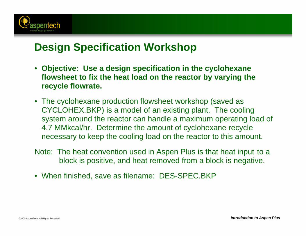
©2000 AspenTech. All Rights Reserved. Introduction to Aspen Plus
Design Specification Workshop
• Objective: Use a design specification in the cyclohexane flowsheet to fix the heat load on the reactor by varying the recycle flowrate.
• The cyclohexane production flowsheet workshop (saved as CYCLOHEX.BKP) is a model of an existing plant. The cooling system around the reactor can handle a maximum operating load of 4.7 MMkcal/hr. Determine the amount of cyclohexane recycle necessary to keep the cooling load on the reactor to this amount.
Note: The heat convention used in Aspen Plus is that heat input to a block is positive, and heat removed from a block is negative.
• When finished, save as filename: DES-SPEC.BKP
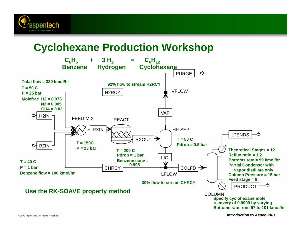
©2000 AspenTech. All Rights Reserved. Introduction to Aspen Plus
Cyclohexane Production WorkshopC6H6 + 3 H2 = C6H12
Benzene Hydrogen Cyclohexane
Use the RK-SOAVE property method
Bottoms rate = 99 kmol/hr
P = 25 barT = 50 C
Molefrac H2 = 0.975N2 = 0.005CH4 = 0.02
Total flow = 330 kmol/hr
T = 40 CP = 1 barBenzene flow = 100 kmol/hr
T = 150CP = 23 bar T = 200 C
Pdrop = 1 barBenzene conv =
0.998
T = 50 CPdrop = 0.5 bar
92% flow to stream H2RCY
30% flow to stream CHRCY
Specify cyclohexane molerecovery of 0.9999 by varyingBottoms rate from 97 to 101 kmol/hr
Theoretical Stages = 12Reflux ratio = 1.2
Partial Condenser with vapor distillate only
Column Pressure = 15 barFeed stage = 8
REACTFEED-MIXH2IN
BZIN
H2RCY
CHRCY
RXIN
RXOUT
HP-SEP
VAP
COLUMN
COLFD
LTENDS
PRODUCT
VFLOW
PURGE
LFLOW
LIQ
©2000 AspenTech. All Rights Reserved.
Calculator Blocks
Objective:Introduce usage of Excel and Fortran Calculator blocks
Aspen Plus References:User Guide, Chapter 19, Calculator Blocks and In-Line Fortran
Related Topics:User Guide, Chapter 20, SensitivityUser Guide, Chapter 21, Design SpecificationsUser Guide, Chapter 18, Accessing Flowsheet VariablesUser Guide, Chapter 22, Optimization
©2000 AspenTech. All Rights Reserved. Introduction to Aspen Plus
Calculator Blocks
• Allows user to write equations in an Excel spreadsheet or in Fortran to be executed by Aspen Plus
• Results of the execution of a Calculator block must be viewed by directly examining the values of the variables modified by the Calculator block.
• Increasing the diagnostics for the Calculator block will print the value of all input and result variables in the Control Panel.
• Located under /Data/Flowsheeting Options/Calculator
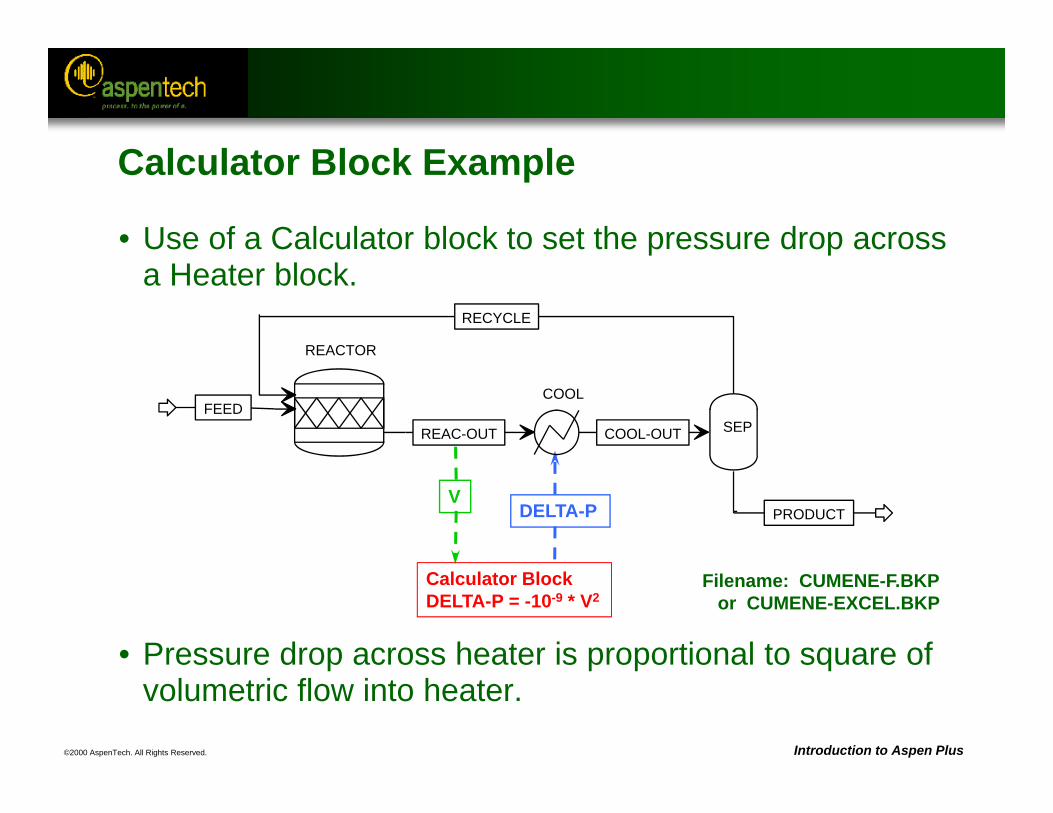
©2000 AspenTech. All Rights Reserved. Introduction to Aspen Plus
• Use of a Calculator block to set the pressure drop across a Heater block.
• Pressure drop across heater is proportional to square of volumetric flow into heater.
Calculator BlockDELTA-P = -10-9 * V2
V
Filename: CUMENE-F.BKPor CUMENE-EXCEL.BKP
DELTA-P
REACTOR
FEED
RECYCLE
REAC-OUT
COOL
COOL-OUT SEP
PRODUCT
Calculator Block Example
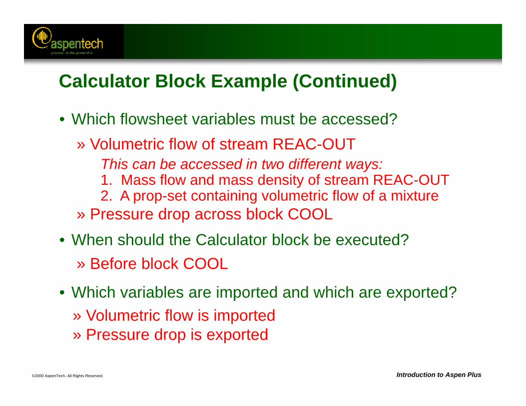
©2000 AspenTech. All Rights Reserved. Introduction to Aspen Plus
• Which flowsheet variables must be accessed?
• When should the Calculator block be executed?
• Which variables are imported and which are exported?
» Volumetric flow of stream REAC-OUTThis can be accessed in two different ways:1. Mass flow and mass density of stream REAC-OUT2. A prop-set containing volumetric flow of a mixture
» Pressure drop across block COOL
» Before block COOL
» Volumetric flow is imported» Pressure drop is exported
Calculator Block Example (Continued)
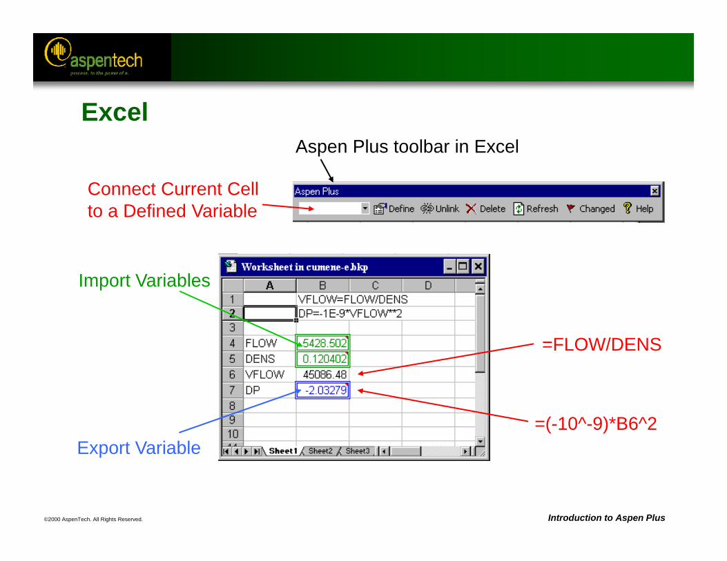
©2000 AspenTech. All Rights Reserved. Introduction to Aspen Plus
Import Variables
Export Variable=(-10^-9)*B6^2
=FLOW/DENS
Connect Current Cell to a Defined Variable
Aspen Plus toolbar in Excel
Excel
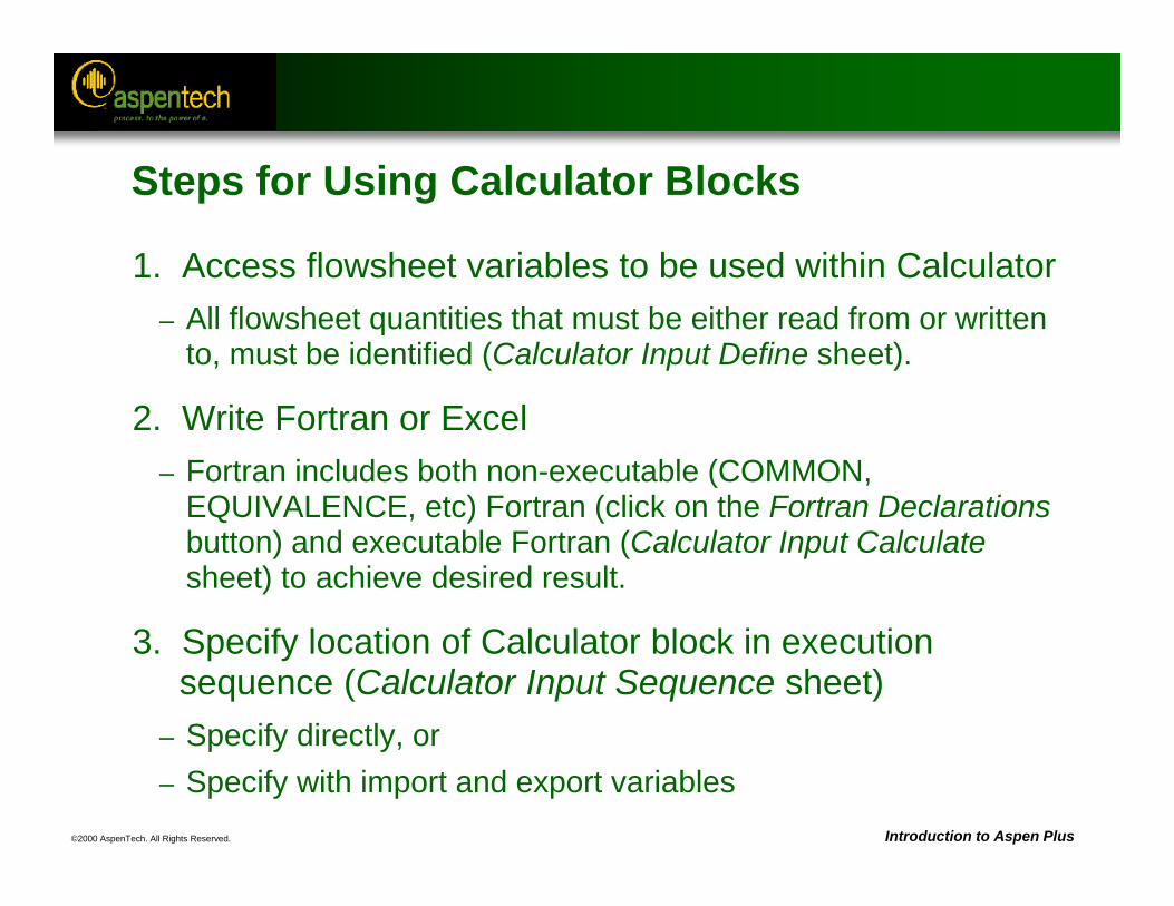
©2000 AspenTech. All Rights Reserved. Introduction to Aspen Plus
Steps for Using Calculator Blocks
1. Access flowsheet variables to be used within Calculator– All flowsheet quantities that must be either read from or written
to, must be identified (Calculator Input Define sheet).
2. Write Fortran or Excel– Fortran includes both non-executable (COMMON,
EQUIVALENCE, etc) Fortran (click on the Fortran Declarationsbutton) and executable Fortran (Calculator Input Calculatesheet) to achieve desired result.
3. Specify location of Calculator block in execution sequence (Calculator Input Sequence sheet)
– Specify directly, or– Specify with import and export variables
©2000 AspenTech. All Rights Reserved. Introduction to Aspen Plus
Uses of Calculator Blocks
• Feed-forward control (setting flowsheet inputs based on upstream calculated values)
• Calling external subroutines
• Input / output to and from external files
• Writing to an external file, or the Control Panel, History File, or Report File
• Custom reports
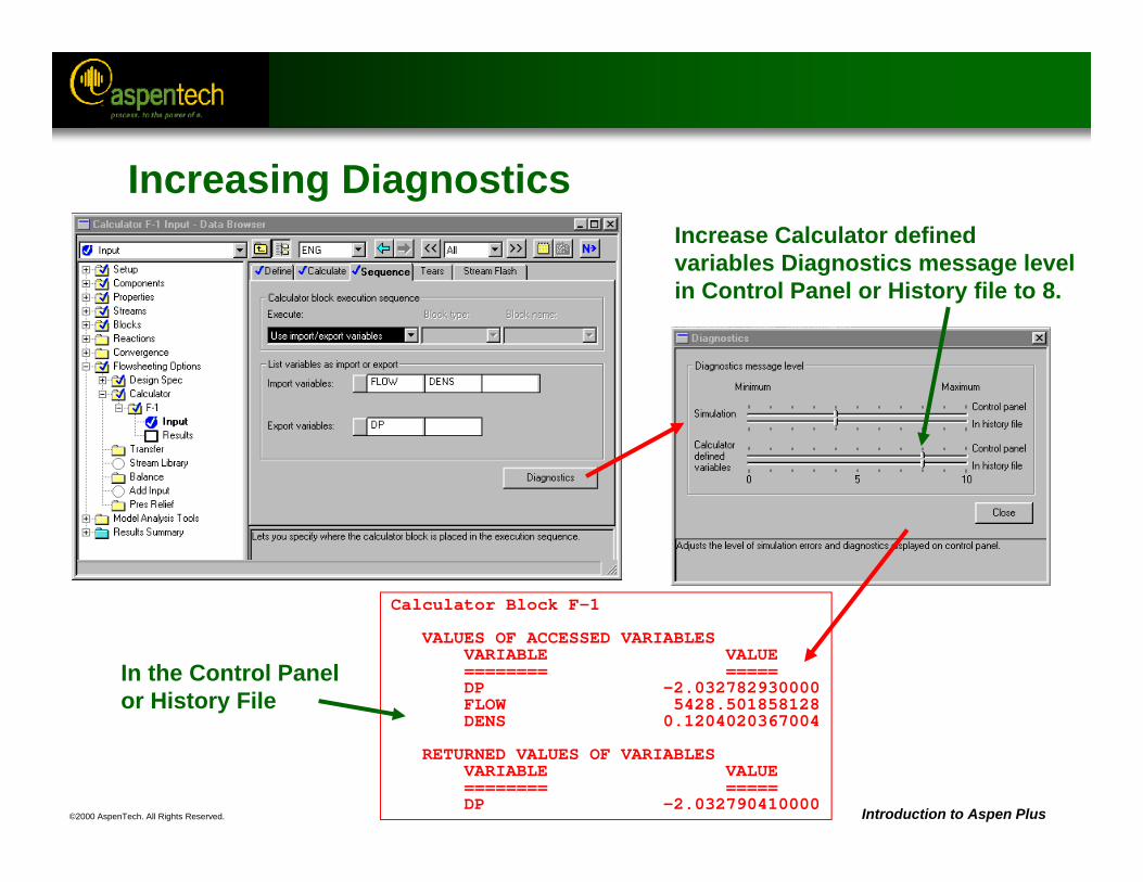
©2000 AspenTech. All Rights Reserved. Introduction to Aspen Plus
Increasing Diagnostics
Calculator Block F-1
VALUES OF ACCESSED VARIABLESVARIABLE VALUE======== =====DP -2.032782930000FLOW 5428.501858128DENS 0.1204020367004
RETURNED VALUES OF VARIABLESVARIABLE VALUE======== =====DP -2.032790410000
Increase Calculator defined variables Diagnostics message level in Control Panel or History file to 8.
In the Control Panel or History File
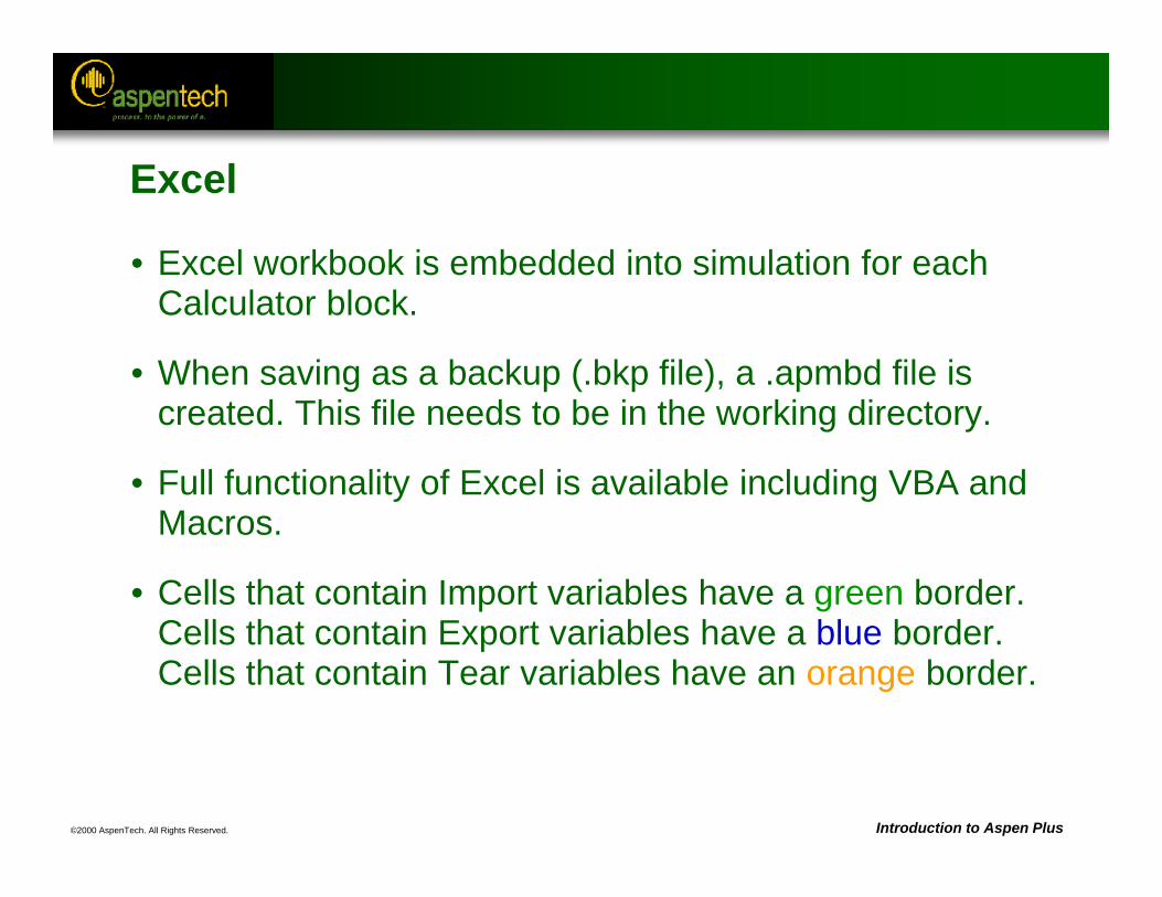
©2000 AspenTech. All Rights Reserved. Introduction to Aspen Plus
Excel
• Excel workbook is embedded into simulation for each Calculator block.
• When saving as a backup (.bkp file), a .apmbd file is created. This file needs to be in the working directory.
• Full functionality of Excel is available including VBA and Macros.
• Cells that contain Import variables have a green border. Cells that contain Export variables have a blue border.Cells that contain Tear variables have an orange border.
©2000 AspenTech. All Rights Reserved. Introduction to Aspen Plus
Excel (Continued)
• Variables can be defined in Aspen Plus on the Define sheet or in Excel using the Aspen Plus toolbar. (It is generally faster to add variables inside Aspen Plus.)
• No Fortran compiler is needed.
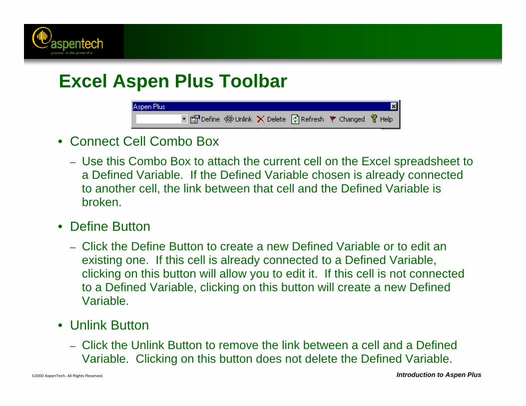
©2000 AspenTech. All Rights Reserved. Introduction to Aspen Plus
Excel Aspen Plus Toolbar
• Connect Cell Combo Box– Use this Combo Box to attach the current cell on the Excel spreadsheet to
a Defined Variable. If the Defined Variable chosen is already connected to another cell, the link between that cell and the Defined Variable is broken.
• Define Button– Click the Define Button to create a new Defined Variable or to edit an
existing one. If this cell is already connected to a Defined Variable, clicking on this button will allow you to edit it. If this cell is not connected to a Defined Variable, clicking on this button will create a new Defined Variable.
• Unlink Button– Click the Unlink Button to remove the link between a cell and a Defined
Variable. Clicking on this button does not delete the Defined Variable.
©2000 AspenTech. All Rights Reserved. Introduction to Aspen Plus
Excel Aspen Plus Toolbar (Continued)
• Delete Button– Click the Delete Button to remove the link between a cell and a
Defined variable and delete the Defined Variable.
• Refresh Button– Click the Refresh Button to refresh the list of Defined Variables in the
Connect Cell Combo Box. You should click this button if you have changed the list of Defined Variables by making changes on the Calculator Define sheet.
• Changed Button– Click the Changed Button to set the "Input Changed" flag of this
Calculator block. This will cause the Calculator to be re-executed the next time you run the simulation. You should click this button if, after the calculator block is executed, you make changes to the Excel spreadsheet without making any changes on the Calculator block forms.

©2000 AspenTech. All Rights Reserved.
Windows Interoperability
Objective:Introduce the use of windows interoperability to transfer
data easily to and from other Windows programs.
Aspen Plus ReferencesUser Guide, Chapter 37, Working with Other Windows ProgramsUser Guide, Chapter 38, Using the Aspen Plus ActiveX Automation Server
©2000 AspenTech. All Rights Reserved. Introduction to Aspen Plus
Windows Interoperability
• Copying and pasting simulation data into spreadsheets or reports
• Copying and pasting flowsheet graphics and plots into reports
• Creating active links between Aspen Plus and other Windows applications
• OLE - Object Linking and Embedding
• ActiveX automation
©2000 AspenTech. All Rights Reserved. Introduction to Aspen Plus
Windows Interoperability - Examples
• Copy simulation results such as column profiles and stream results into– Spreadsheet for further analysis– Word processor for reports and documentation– Design program– Database for case storage and management
• Copy flowsheet graphics and plots into– Word processor for reports – Slide making program for presentations
• Copy tabular data from spreadsheets into Aspen Plus for Data Regression, Data-Fit, etc.
• Copy plots or tables into the Process Flowsheet Window.
©2000 AspenTech. All Rights Reserved. Introduction to Aspen Plus
Benefits of Windows Interoperability
• Benefits of Copy/Paste/Paste Link– Live data links can be established that update these
applications as the process model is changed to automatically propagate results of engineering changes.
– The benefits to the engineer are quick and error-free data transfer and consistent engineering results throughout the engineering work process.
©2000 AspenTech. All Rights Reserved. Introduction to Aspen Plus
Steps for Using Copy and Paste
1. Select – Select the data fields or the graphical objects.
• Multiple fields of data or objects can be selected by holding down the CTRL key while clicking the mouse on the fields.
• Columns of data can be selected by clicking the column heading, or an entire grid can be selected by clicking on the top left cell.
2. Copy– Choose Copy from the Edit menu or type CTRL-C.
3. Paste– Click the mouse in the input field where you want the
information and choose Paste from the Edit menu or click CTRL-V.
©2000 AspenTech. All Rights Reserved. Introduction to Aspen Plus
OLE - Object Linking and Embedding
• What is OLE?– Applications can be used within applications.
• Uses of OLE– Aspen Plus as the OLE server: Aspen Plus flowsheet graphics
can be embedded into a report document, or stream data into a CAD drawing. The simulation model is actually contained in the document, and could be delivered directly with that document.
– Aspen Plus as the OLE container: Other windows applications can be embedded within the Aspen Plus simulation.
©2000 AspenTech. All Rights Reserved. Introduction to Aspen Plus
OLE (Continued)
• Examples of OLE– OLE server: If the recipient of an engineering report, for
example, wanted to review the model assumptions, he could access and run the embedded Aspen Plus model directly from the report document.
– OLE container: For example, Excel spreadsheets and plots could be used to enhance Aspen Plus flowsheet graphics.
©2000 AspenTech. All Rights Reserved. Introduction to Aspen Plus
Embedding Objects in the Flowsheet
• You can embed other applications as objects into the Process Flowsheet window.
• You can do this in two ways:– Using Copy and Paste– Using the Insert dialog box
• You can edit the object embedded in the flowsheet by double clicking on the object to edit it inside Aspen Plus.
• You can also move, resize or attach the object to a block or stream in the flowsheet.
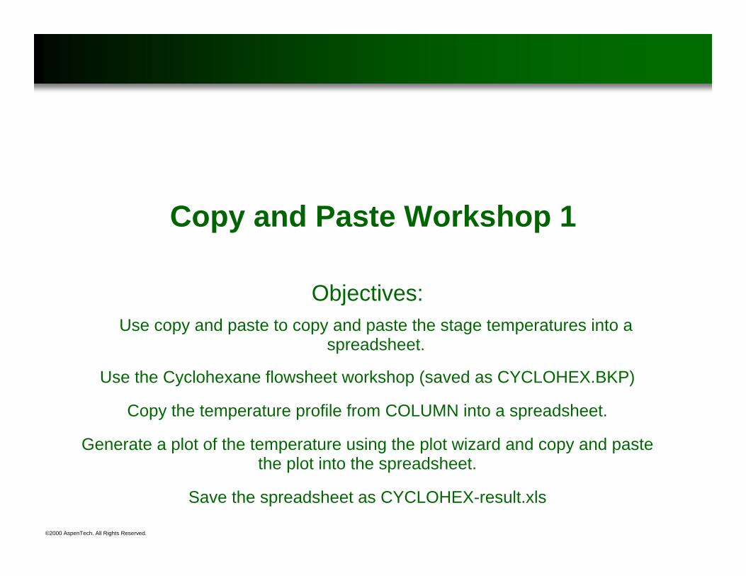
©2000 AspenTech. All Rights Reserved.
Copy and Paste Workshop 1
Objectives:Use copy and paste to copy and paste the stage temperatures into a
spreadsheet.
Use the Cyclohexane flowsheet workshop (saved as CYCLOHEX.BKP)
Copy the temperature profile from COLUMN into a spreadsheet.
Generate a plot of the temperature using the plot wizard and copy and paste the plot into the spreadsheet.
Save the spreadsheet as CYCLOHEX-result.xls
©2000 AspenTech. All Rights Reserved. Introduction to Aspen Plus
Copy and Paste Workshop 2
• Objective: Use copy and paste to copy the stream results to a stream input form.
• Use the Cyclohexane flowsheet workshop (saved as CYCLOHEX.BKP)
• Copy the stream results from stream RXIN into the input form.– Copy the compositions, the temperature and the pressure
separately.
Note: Reinitialize before running the simulation in order to see how many iterations are needed before and after the estimate is added.
©2000 AspenTech. All Rights Reserved. Introduction to Aspen Plus
Creating Active Links
• When copying and pasting information, you can create active links between input or results fields in Aspen Plus and other applications such as Word and Excel.
• The links update these applications as the process model is modified to automatically propagate results of engineering changes.
©2000 AspenTech. All Rights Reserved. Introduction to Aspen Plus
Steps for Creating Active Links
1. Open both applications.
2. Select the data (or object) that you want to paste and link.
3. Choose Copy from the Edit menu.
4. In the location where you want to paste the link, choose Paste Special from the Edit menu.
5. In the Paste Special dialog box, click the Paste Link radio button.
©2000 AspenTech. All Rights Reserved. Introduction to Aspen Plus
Paste Link Demonstration
• Objective: Create an active link from Aspen Plus Results into a spreadsheet.
• Start with the cumene flowsheet demonstration.
• Open a spreadsheet and create a cell with the temperature for the cooler in it.
• Copy and paste the link into the Aspen Plus flowsheet.
• Copy and paste a link with the flow and composition of cumene in the product stream into the spreadsheet.
• Change the temperature in the spreadsheet and then rerun the flowsheet. Notice the changes.
©2000 AspenTech. All Rights Reserved. Introduction to Aspen Plus
Paste Link Workshop
• Objective: Create an active link from Aspen Plus results into a spreadsheet
• Use the Cyclohexane flowsheet workshop (saved as CYCLOHEX.BKP)
• Copy the Condenser and Reboiler duty results from the RadFrac COLUMN Summary sheet. Use Copy with Format and copy the value, the label and the units.
• Paste the results into the CYCLOHEX-results.xls spreadsheet as a link. Use Paste Special and choose Link.
• Change the Reflux ratio in the column to 2 and rerun the flowsheet. Check the spreadsheet to see that the results have changed there also. Notice that the temperature profile results have not changed since they were not pasted as a link.
©2000 AspenTech. All Rights Reserved. Introduction to Aspen Plus
Saving Files with Active Links
• Be sure to save both the link source file and the link container file.
• If you save the link source with a different name, you must save the link container after saving the link source.
• If you have active links in both directions between the two applications and you change the name of both files, you must do three Save operations:– Save the first application with a new name.– Save the second application with a new name.– Save the first application again.
©2000 AspenTech. All Rights Reserved. Introduction to Aspen Plus
Running Files with Active Links
• When you open the link source file, there is nothing special that you need to do.
• When you open the link container file, you will usually see a dialog box asking you if you want to re-establish the links. You can select Yes or No.
• To make a link source application visible:– Select Links, from the Edit menu in Aspen Plus.– In the Links dialog box, select the source file and click Open
Source.
Note: The Process Flowsheet must be the active window. Links is not an option on the Edit menu if the Data Browser is active.
©2000 AspenTech. All Rights Reserved.
Heat Exchangers
Objective:Introduce the unit operation models used for heat
exchangers and heaters.
Aspen Plus References:Unit Operation Models Reference Manual, Chapter 3, Heat Exchangers
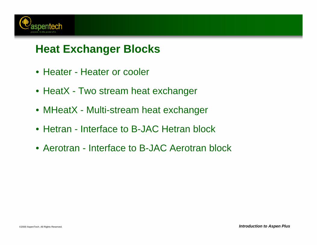
©2000 AspenTech. All Rights Reserved. Introduction to Aspen Plus
Heat Exchanger Blocks
• Heater - Heater or cooler
• HeatX - Two stream heat exchanger
• MHeatX - Multi-stream heat exchanger
• Hetran - Interface to B-JAC Hetran block
• Aerotran - Interface to B-JAC Aerotran block
©2000 AspenTech. All Rights Reserved. Introduction to Aspen Plus
Working with the Heater Model
• The Heater block mixes multiple inlet streams to produce a single outlet stream at a specified thermodynamic state.
• Heater can be used to represent:– Heaters– Coolers– Valves– Pumps (when work-related results are not needed)– Compressors (when work-related results are not needed)
• Heater can also be used to set the thermodynamic conditions of a stream.
©2000 AspenTech. All Rights Reserved. Introduction to Aspen Plus
Heater Input Specifications
• Allowed combinations:– Pressure (or Pressure drop) and one of:
• Outlet temperature• Heat duty or inlet heat stream• Vapor fraction• Temperature change• Degrees of subcooling or superheating
– Outlet Temperature or Temperature change and one of:• Pressure• Heat Duty• Vapor fraction
©2000 AspenTech. All Rights Reserved. Introduction to Aspen Plus
Heater Input Specifications (Continued)
• For single phase use Pressure (drop) and one of:– Outlet temperature– Heat duty or inlet heat stream– Temperature change
• Vapor fraction of 1 means dew point condition, 0 means bubble point
©2000 AspenTech. All Rights Reserved. Introduction to Aspen Plus
Heat Streams
• Any number of inlet heat streams can be specified for a Heater.
• One outlet heat stream can be specified for the net heat load from a Heater.
• The net heat load is the sum of the inlet heat streams minus the actual (calculated) heat duty.
• If you give only one specification (temperature or pressure), Heater uses the sum of the inlet heat streams as a duty specification.
• If you give two specifications, Heater uses the heat streams only to calculate the net heat duty.
©2000 AspenTech. All Rights Reserved. Introduction to Aspen Plus
Working with the HeatX Model
• HeatX can perform simplified or rigorous rating calculations.
• Simplified rating calculations (heat and material balance calculations) can be performed if exchanger geometry is unknown or unimportant.
• For rigorous heat transfer and pressure drop calculations, the heat exchanger geometry must be specified.
©2000 AspenTech. All Rights Reserved. Introduction to Aspen Plus
Working with the HeatX Model (Continued)
• HeatX can model shell-and-tube exchanger types:– Counter-current and co-current– Segmental baffle TEMA E, F, G, H, J and X shells– Rod baffle TEMA E and F shells– Bare and low-finned tubes
• HeatX performs:– Full zone analysis– Heat transfer and pressure drop calculations– Sensible heat, nucleate boiling, condensation
film coefficient calculations– Built-in or user specified correlations
©2000 AspenTech. All Rights Reserved. Introduction to Aspen Plus
Working with the HeatX Model (Continued)
• HeatX cannot:– Perform design calculations– Perform mechanical vibration analysis– Estimate fouling factors
©2000 AspenTech. All Rights Reserved. Introduction to Aspen Plus
HeatX Input Specifications
• Select one of the following specifications:– Heat transfer area or Geometry– Exchanger duty– For hot or cold outlet stream:
• Temperature• Temperature change • Temperature approach • Degrees of superheating / subcooling• Vapor fraction
©2000 AspenTech. All Rights Reserved. Introduction to Aspen Plus
Working with the MHeatX Model
• MHeatX can be used to represent heat transfer between multiple hot and cold streams.
• Detailed, rigorous internal zone analysis can be performed to determine pinch points.
• MHeatX uses multiple Heater blocks and heat streams to enhance flowsheet convergence.
• Two-stream heat exchangers can also be modeled using MHeatX.
©2000 AspenTech. All Rights Reserved. Introduction to Aspen Plus
HeatX versus Heater
• Consider the following:– Use HeatX when both sides are important.– Use Heater when one side (e.g. the utility) is not important.– Use two Heaters (coupled by heat stream, Calculator block or
design spec) or an MHeatX to avoid flowsheet complexity created by HeatX.
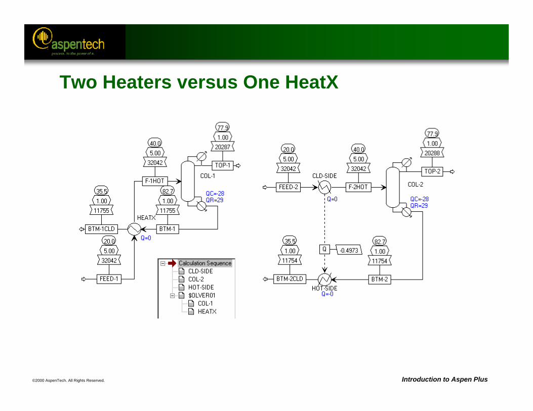
©2000 AspenTech. All Rights Reserved. Introduction to Aspen Plus
Two Heaters versus One HeatX
©2000 AspenTech. All Rights Reserved. Introduction to Aspen Plus
Working with Hetran and Aerotran
• The Hetran block is the interface to the B-JAC Hetran program for designing and simulating shell and tube heat exchangers.
• The Aerotran block is the interface to the B-JAC Aerotran program for designing and simulating air-cooled heat exchangers.
• Information related to the heat exchanger configuration and geometry is entered through the Hetran or Aerotran standalone program interface.
©2000 AspenTech. All Rights Reserved. Introduction to Aspen Plus
Working with HTRI-IST
• The HTRIIST block called HTRI IST as a subroutine for licensed IST users only.
• Aspen Plus properties are used.
• Users can create a new IST model or access an existing model.
• Key IST results are retrieved and reported inside Aspen Plus.
©2000 AspenTech. All Rights Reserved. Introduction to Aspen Plus
Heat Curves
• All of the heat exchanger models are able to calculate Heat Curves (Hcurves).
• Tables can be generated for various independent variables (typically duty or temperature) for any property that Aspen Plus can generate.
• These tables can be printed, plotted, or exported for use with other heat exchanger design software.
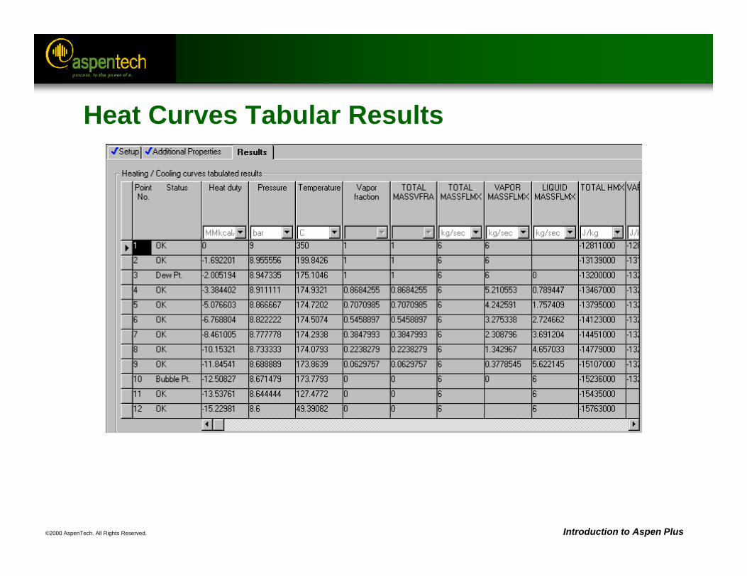
©2000 AspenTech. All Rights Reserved. Introduction to Aspen Plus
Heat Curves Tabular Results
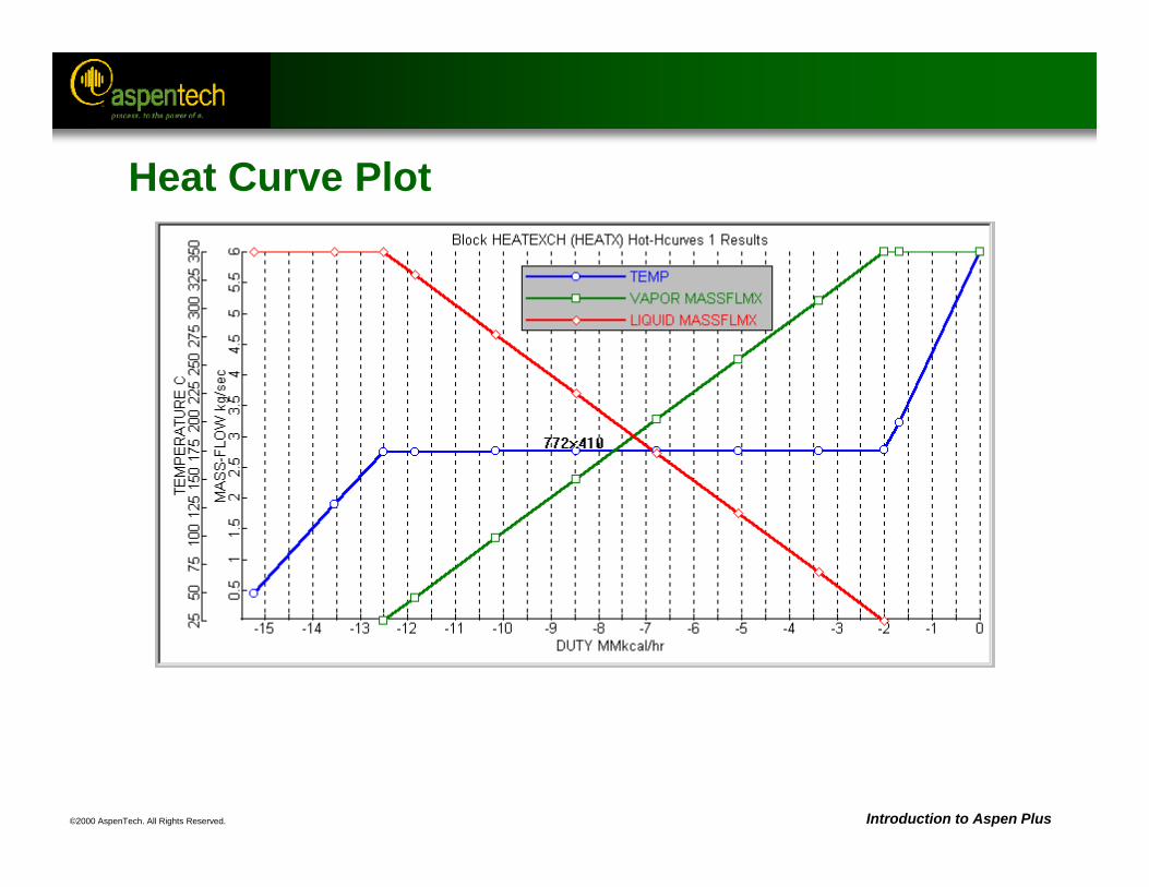
©2000 AspenTech. All Rights Reserved. Introduction to Aspen Plus
Heat Curve Plot
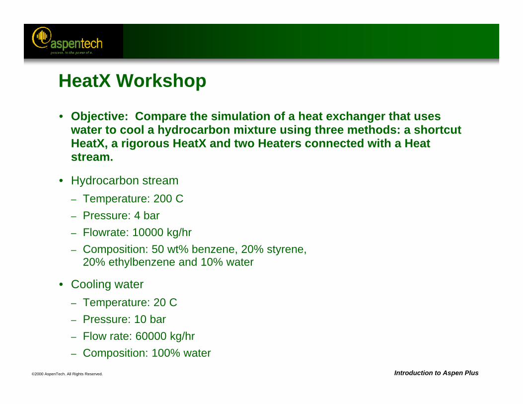
©2000 AspenTech. All Rights Reserved. Introduction to Aspen Plus
HeatX Workshop
• Objective: Compare the simulation of a heat exchanger that uses water to cool a hydrocarbon mixture using three methods: a shortcut HeatX, a rigorous HeatX and two Heaters connected with a Heat stream.
• Hydrocarbon stream– Temperature: 200 C– Pressure: 4 bar– Flowrate: 10000 kg/hr– Composition: 50 wt% benzene, 20% styrene,
20% ethylbenzene and 10% water
• Cooling water – Temperature: 20 C– Pressure: 10 bar– Flow rate: 60000 kg/hr– Composition: 100% water
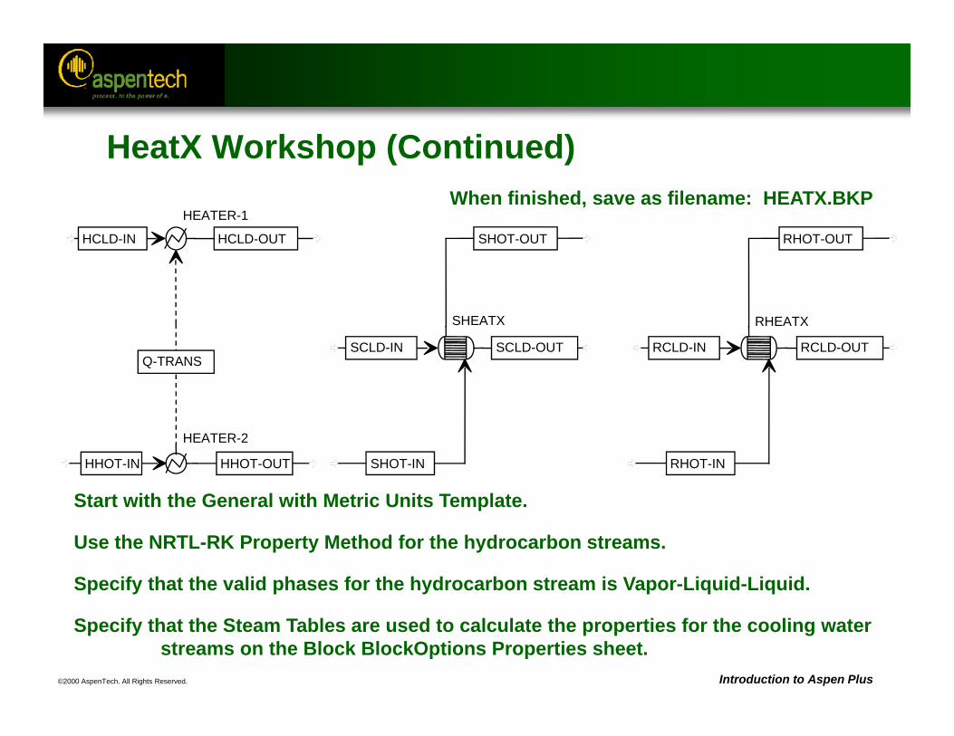
©2000 AspenTech. All Rights Reserved. Introduction to Aspen Plus
RHEATX
RHOT-IN
RCLD-IN RCLD-OUT
RHOT-OUT
SHEATX
SHOT-IN
SCLD-IN SCLD-OUT
SHOT-OUT
HEATER-1
HCLD-IN
Q-TRANS
HCLD-OUT
HEATER-2
HHOT-IN HHOT-OUT
Start with the General with Metric Units Template.
Use the NRTL-RK Property Method for the hydrocarbon streams.
Specify that the valid phases for the hydrocarbon stream is Vapor-Liquid-Liquid.
Specify that the Steam Tables are used to calculate the properties for the cooling water streams on the Block BlockOptions Properties sheet.
When finished, save as filename: HEATX.BKP
HeatX Workshop (Continued)
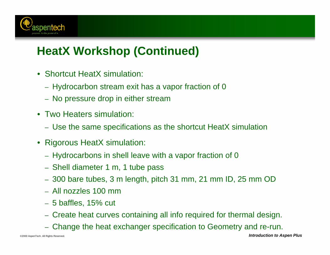
©2000 AspenTech. All Rights Reserved. Introduction to Aspen Plus
HeatX Workshop (Continued)
• Shortcut HeatX simulation:– Hydrocarbon stream exit has a vapor fraction of 0– No pressure drop in either stream
• Two Heaters simulation:– Use the same specifications as the shortcut HeatX simulation
• Rigorous HeatX simulation:– Hydrocarbons in shell leave with a vapor fraction of 0– Shell diameter 1 m, 1 tube pass– 300 bare tubes, 3 m length, pitch 31 mm, 21 mm ID, 25 mm OD– All nozzles 100 mm– 5 baffles, 15% cut– Create heat curves containing all info required for thermal design.– Change the heat exchanger specification to Geometry and re-run.
©2000 AspenTech. All Rights Reserved.
Pressure Changers
Objective:Introduce the unit operation models used to change pressure:
pumps, compressors, and models for calculating pressure change through pipes and valves.
Aspen Plus References:Unit Operation Models Reference Manual, Chapter 6, Pressure Changers
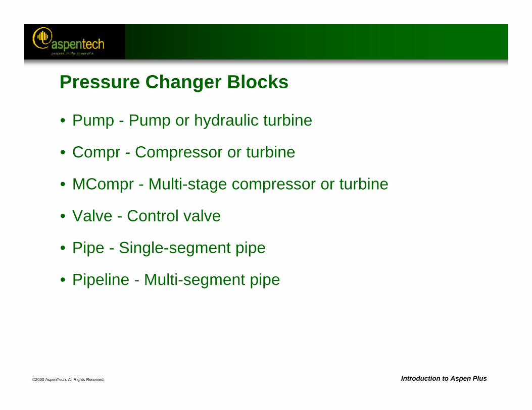
©2000 AspenTech. All Rights Reserved. Introduction to Aspen Plus
Pressure Changer Blocks
• Pump - Pump or hydraulic turbine
• Compr - Compressor or turbine
• MCompr - Multi-stage compressor or turbine
• Valve - Control valve
• Pipe - Single-segment pipe
• Pipeline - Multi-segment pipe
©2000 AspenTech. All Rights Reserved. Introduction to Aspen Plus
Working with the Pump Model
• The Pump block can be used to simulate: – Pumps– Hydraulic turbines
• Power requirement is calculated or input.
• A Heater model can be used for pressure change calculations only.
• Pump is designed to handle a single liquid phase.
• Vapor-liquid or vapor-liquid-liquid calculations can be specified to check outlet stream phases.

©2000 AspenTech. All Rights Reserved. Introduction to Aspen Plus
Pump Performance Curves
• Rating can be done by specifying scalar parameters or a pump performance curve.
• Specify:– Dimensional curves
• Head versus flow• Power versus flow
– Dimensionless curves:• Head coefficient versus flow coefficient
©2000 AspenTech. All Rights Reserved. Introduction to Aspen Plus
Working with the Compr Model
• The Compr block can be used to simulate:– Polytropic centrifugal compressor– Polytropic positive displacement compressor– Isentropic compressor– Isentropic turbine
• MCompr is used for multi-stage compressors.
• Power requirement is calculated or input.
• A Heater model can be used for pressure change calculations only.
• Compr is designed to handle both single and multiple phase calculations.
©2000 AspenTech. All Rights Reserved. Introduction to Aspen Plus
Working with the MCompr Model
• The MCompr block can be used to simulate:– Multi-stage polytropic centrifugal compressor– Multi-stage polytropic positive displacement compressor– Multi-stage isentropic compressor– Multi-stage isentropic turbine
• MCompr can have an intercooler between each stage, and an aftercooler after the last stage. – You can perform one-, two-, or three- phase flash calculations
in the intercoolers. – Each cooler can have a liquid knockout stream, except the
cooler after the last stage.– Intercooler specifications apply to all subsequent coolers.
©2000 AspenTech. All Rights Reserved. Introduction to Aspen Plus
Compressor Performance Curves
• Rating can be done by specifying a compressor performance curve.
• Specify:– Dimensional curves
• Head versus flow• Power versus flow
– Dimensionless curves:• Head coefficient versus flow coefficient
• Compr cannot handle performance curves for a turbine.
©2000 AspenTech. All Rights Reserved. Introduction to Aspen Plus
Work Streams
• Any number of inlet work streams can be specified for pumps and compressors.
• One outlet work stream can be specified for the net work load from pumps or compressors.
• The net work load is the sum of the inlet work streams minus the actual (calculated) work.
©2000 AspenTech. All Rights Reserved. Introduction to Aspen Plus
Working with the Valve Model
• The Valve block can be used to simulate:– Control valves– Pressure drop
• The pressure drop across a valve is related to the valve flow coefficient.
• Flow is assumed to be adiabatic.
• Valve can perform single or multiple phase calculations.
©2000 AspenTech. All Rights Reserved. Introduction to Aspen Plus
Working with the Valve Model (Continued)
• The effect of head loss from pipe fittings can be included.
• There are three types of calculations:– Adiabatic flash for specified outlet pressure (pressure changer)– Calculate valve flow coefficient for specified outlet pressure
(design)– Calculate outlet pressure for specified valve (rating)
• Valve can check for choked flow.
• Cavitation index can be calculated.

©2000 AspenTech. All Rights Reserved. Introduction to Aspen Plus
Working with the Pipe Model
• The Pipe block calculates the pressure drop and heat transfer in a single pipe segment.
• The Pipeline block can be used for a multiple-segment pipe.
• Pipe can perform single or multiple phase calculations.
• If the inlet pressure is known, Pipe calculates the outlet pressure.
• If the outlet pressure is known, Pipe calculates the inlet pressure and updates the state variables of the inlet stream.
• Entrance effects are not modeled.
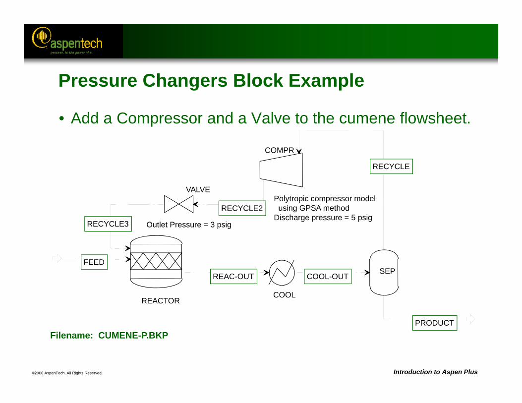
©2000 AspenTech. All Rights Reserved. Introduction to Aspen Plus
Filename: CUMENE-P.BKP
REACTOR
FEED
RECYCLE
REAC-OUT
COOL
COOL-OUTSEP
PRODUCT
COMPR
RECYCLE2
VALVE
RECYCLE3 Outlet Pressure = 3 psig
Polytropic compressor model using GPSA method
Discharge pressure = 5 psig
Pressure Changers Block Example
• Add a Compressor and a Valve to the cumene flowsheet.
©2000 AspenTech. All Rights Reserved. Introduction to Aspen Plus
Pressure Changers Workshop
• Objective: Add pressure changer unit operations to the Cyclohexane flowsheet.
• Start with the Cyclohexane Workshop flowsheet (CYCLOHEX.BKP)
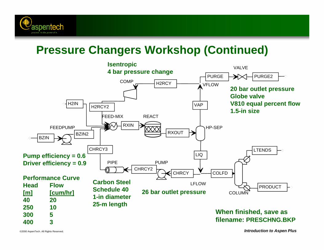
©2000 AspenTech. All Rights Reserved. Introduction to Aspen Plus
FEED-MIX
H2IN
CHRCY3
H2RCY2
BZIN2
RXIN
REACT
RXOUTHP-SEP
LIQ
VAP
COLUMN
COLFD
LTENDS
PRODUCT
VFLOWH2RCYPURGE
LFLOW
CHRCY
PUMPCHRCY2
PIPE
COMP
FEEDPUMP
BZIN
VALVE
PURGE2
When finished, save asfilename: PRESCHNG.BKP
Pump efficiency = 0.6Driver efficiency = 0.9
Performance CurveHead Flow[m] [cum/hr]40 20250 10300 5400 3
Carbon SteelSchedule 401-in diameter25-m length
26 bar outlet pressure
20 bar outlet pressureGlobe valveV810 equal percent flow1.5-in size
Isentropic4 bar pressure change
Pressure Changers Workshop (Continued)
©2000 AspenTech. All Rights Reserved.
Flowsheet Convergence
Objective:Introduce the idea of convergence blocks, tear
streams and flowsheet sequences
Aspen Plus ReferencesUser Guide, Chapter 17, Convergence
©2000 AspenTech. All Rights Reserved. Introduction to Aspen Plus
Convergence Blocks
• Every design specification and tear stream has an associated convergence block.
• Convergence blocks determine how guesses for a tear stream or design specification manipulated variable are updated from iteration to iteration.
• Aspen Plus-defined convergence block names begin with the character “$.”– User defined convergence block names must not begin with the
character “$.”
• To determine the convergence blocks defined by Aspen Plus, look under the “Flowsheet Analysis” section in the Control Panel messages.
• User convergence blocks can be specified under /Data/Convergence/Convergence...
©2000 AspenTech. All Rights Reserved. Introduction to Aspen Plus
Convergence Block Types
• Different types of convergence blocks are used for different purposes:– To converge tear streams:
• WEGSTEIN • DIRECT• BROYDEN• NEWTON
– To converge design specifications:• SECANT• BROYDEN• NEWTON
– To converge design specifications and tear streams:• BROYDEN• NEWTON
– For optimization:• SQP• COMPLEX
• Global convergence options can be specified on the Convergence ConvOptions Defaults form.
©2000 AspenTech. All Rights Reserved. Introduction to Aspen Plus
Flowsheet Sequence
• To determine the flowsheet sequence calculated by Aspen Plus, look under the “COMPUTATION ORDER FOR THE FLOWSHEET” section in the Control Panel, or on the left-hand pane of the Control Panel window.
• User-determined sequences can be specified on the Convergence Sequence form.
• User-specified sequences can be either full or partial.
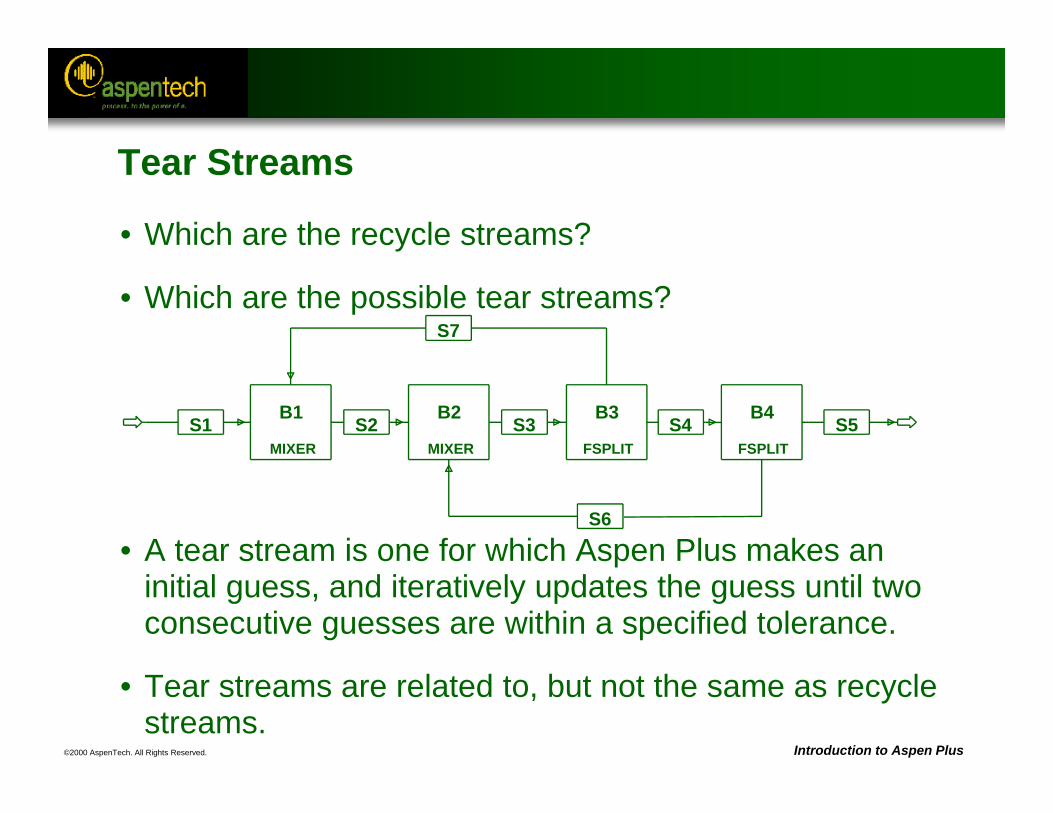
©2000 AspenTech. All Rights Reserved. Introduction to Aspen Plus
• Which are the recycle streams?
• Which are the possible tear streams?
• A tear stream is one for which Aspen Plus makes an initial guess, and iteratively updates the guess until two consecutive guesses are within a specified tolerance.
• Tear streams are related to, but not the same as recycle streams.
S1 S2 S3
S6
S4
S7
S5MIXER
B1
MIXER
B2
FSPLIT
B3
FSPLIT
B4
Tear Streams
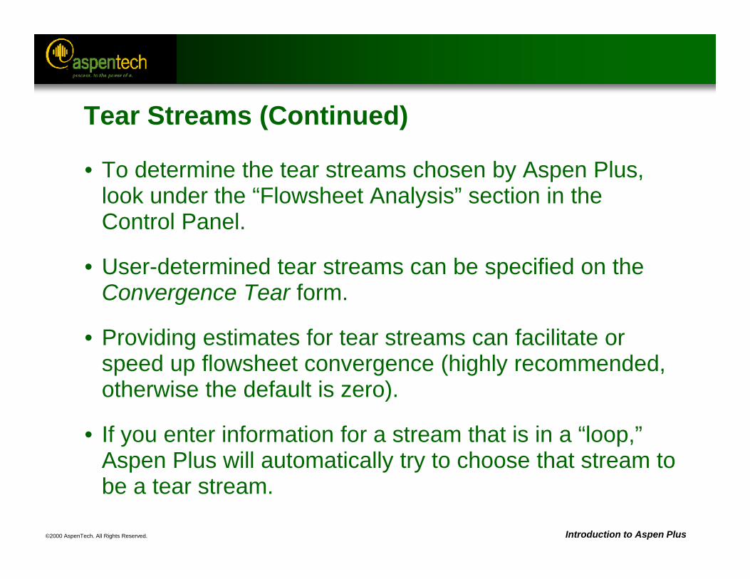
©2000 AspenTech. All Rights Reserved. Introduction to Aspen Plus
Tear Streams (Continued)
• To determine the tear streams chosen by Aspen Plus, look under the “Flowsheet Analysis” section in the Control Panel.
• User-determined tear streams can be specified on the Convergence Tear form.
• Providing estimates for tear streams can facilitate or speed up flowsheet convergence (highly recommended, otherwise the default is zero).
• If you enter information for a stream that is in a “loop,” Aspen Plus will automatically try to choose that stream to be a tear stream.
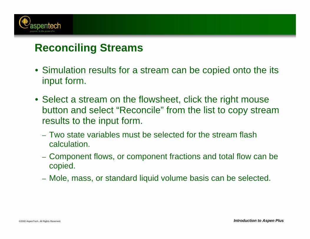
©2000 AspenTech. All Rights Reserved. Introduction to Aspen Plus
Reconciling Streams
• Simulation results for a stream can be copied onto the its input form.
• Select a stream on the flowsheet, click the right mouse button and select “Reconcile” from the list to copy stream results to the input form.– Two state variables must be selected for the stream flash
calculation.– Component flows, or component fractions and total flow can be
copied.– Mole, mass, or standard liquid volume basis can be selected.
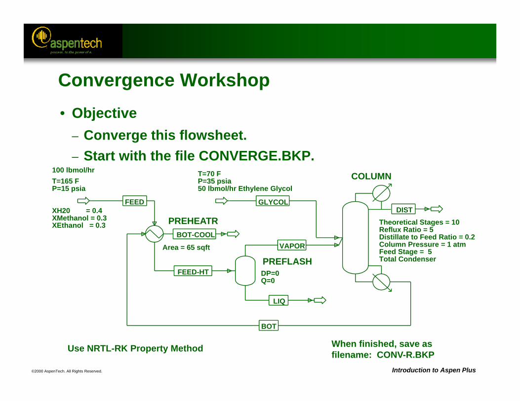
©2000 AspenTech. All Rights Reserved. Introduction to Aspen Plus
• Objective– Converge this flowsheet. – Start with the file CONVERGE.BKP.
LIQ
VAPOR
FEED-HT
FEED
BOT
DIST
BOT-COOL
GLYCOL
COLUMN
PREHEATR
PREFLASH
T=165 FP=15 psia
100 lbmol/hr
XH20 = 0.4XMethanol = 0.3XEthanol = 0.3
Area = 65 sqft
DP=0Q=0
Theoretical Stages = 10Reflux Ratio = 5Distillate to Feed Ratio = 0.2
Feed Stage = 5Column Pressure = 1 atm
Total Condenser
Use NRTL-RK Property Method
T=70 FP=35 psia50 lbmol/hr Ethylene Glycol
When finished, save asfilename: CONV-R.BKP
Convergence Workshop
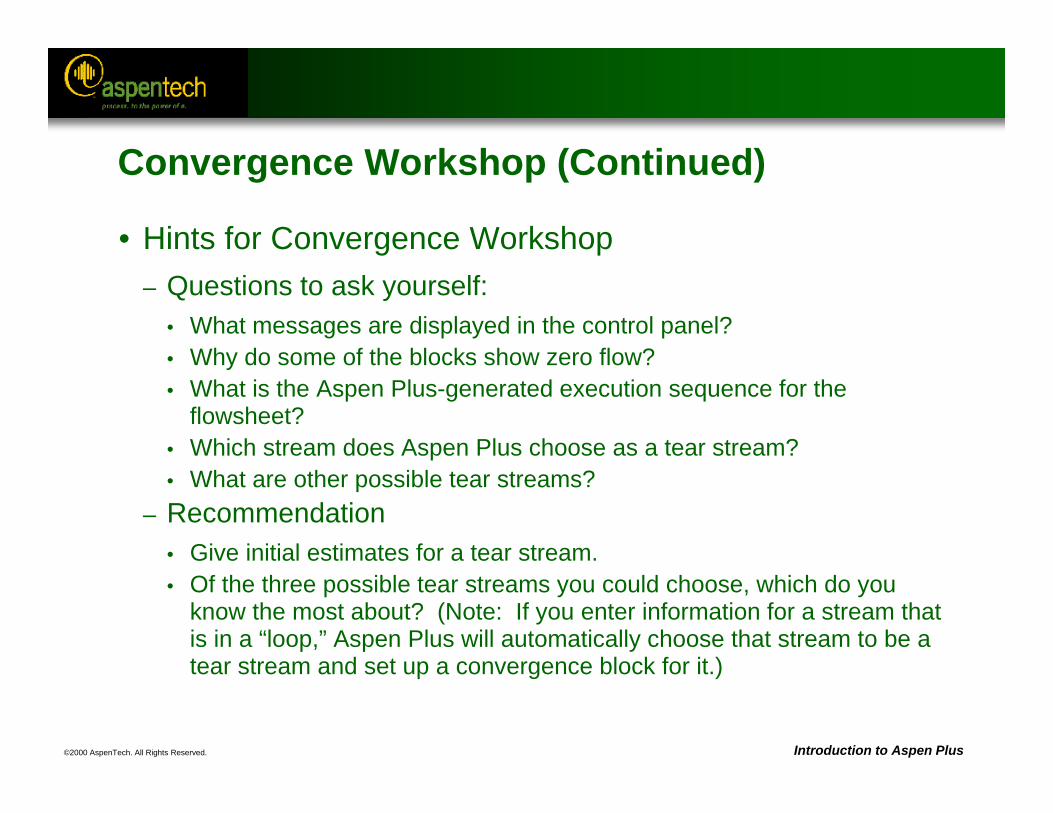
©2000 AspenTech. All Rights Reserved. Introduction to Aspen Plus
Convergence Workshop (Continued)
• Hints for Convergence Workshop– Questions to ask yourself:
• What messages are displayed in the control panel?• Why do some of the blocks show zero flow?• What is the Aspen Plus-generated execution sequence for the
flowsheet?• Which stream does Aspen Plus choose as a tear stream?• What are other possible tear streams?
– Recommendation• Give initial estimates for a tear stream.• Of the three possible tear streams you could choose, which do you
know the most about? (Note: If you enter information for a stream that is in a “loop,” Aspen Plus will automatically choose that stream to be a tear stream and set up a convergence block for it.)
©2000 AspenTech. All Rights Reserved. Introduction to Aspen Plus
Convergence Workshop (Continued)
• Questions to ask yourself:– Does the flowsheet converge after entering initial estimates for the tear
stream?– If not, why not? (see control panel)– How is the err/tol value behaving, and what is its value at the end of the run?– Does it appear that increasing the number of convergence iterations will help?– What else can be tried to improve this convergence?
• Recommendation– Try a different convergence algorithm (e.g. Direct, Broyden, or Newton).
Note: You can either manually create a convergence block to converge the tear stream of your choice, or you can change the default convergence method for all tear streams on the Convergence Conv Options Defaults Default Methods sheet.
©2000 AspenTech. All Rights Reserved. Introduction to Aspen Plus
Full-Scale Plant Modeling Workshop
• Objective: Practice and apply many of the techniques used in this course and learn how to best approach modeling projects
©2000 AspenTech. All Rights Reserved. Introduction to Aspen Plus
Full-Scale Plant Modeling Workshop
• Objective: Model a methanol plant.
• The process being modeled is a methanol plant. The basic feed streams to the plant are Natural Gas, Carbon Dioxide (assumed to be taken from a nearby Ammonia Plant) and Water. The aim is to achieve the methanol production rate of approximately 62,000 kg/hr, at a purity of at least 99.95 % wt.
• This is a large flowsheet that would take an experienced engineer more than an afternoon to complete. Start building the flowsheet and think about how you would work to complete the project.
©2000 AspenTech. All Rights Reserved. Introduction to Aspen Plus
General Guidelines
• Build the flowsheet one section at a time.
• Simplify whenever possible. Complexity can always be added later.
• Investigate the physical properties.– Use Analysis.– Check if binary parameters are available.– Check for two liquid phases.– Use an appropriate equation of state for the portions of the
flowsheet involving gases and use an activity coefficient model for the sections where non-ideal liquids may be present.
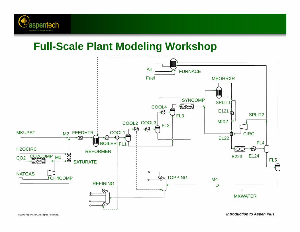
©2000 AspenTech. All Rights Reserved. Introduction to Aspen Plus
FURNACEFuel
Air
MEOHRXR
SPLIT1
MIX2
E121COOL4
FL3
SYNCOMP
FL1
FL2COOL1
COOL3COOL2
BOILERE122
CIRC
E124E223
FL4
SPLIT2
FL5
M4
MKWATER
TOPPINGREFINING
M2
SATURATE
FEEDHTR
REFORMER
NATGAS
H2OCIRC
MKUPST
CH4COMP
CO2 CO2COMP M1
Full-Scale Plant Modeling Workshop
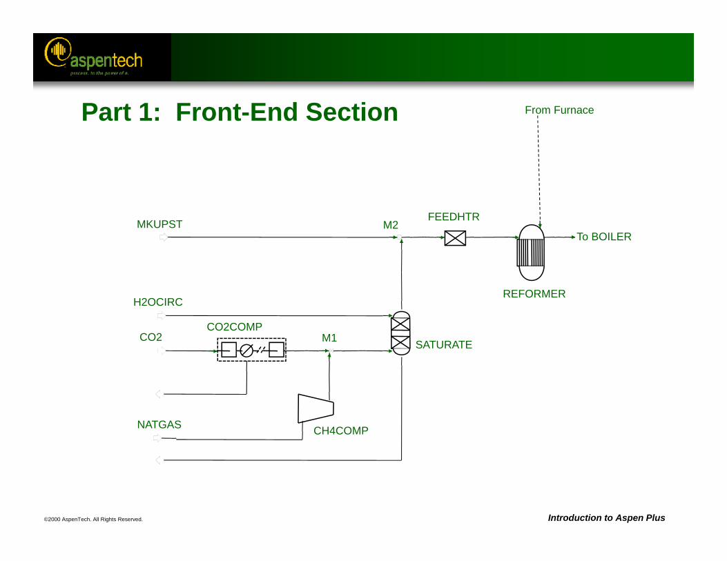
©2000 AspenTech. All Rights Reserved. Introduction to Aspen Plus
M2
SATURATE
FEEDHTR
REFORMER
NATGAS
H2OCIRC
MKUPST
CH4COMP
CO2CO2COMP
From Furnace
To BOILER
M1
Part 1: Front-End Section
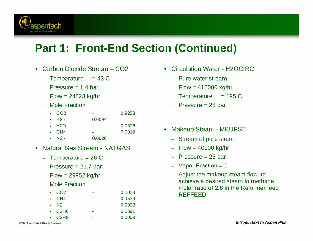
©2000 AspenTech. All Rights Reserved. Introduction to Aspen Plus
Part 1: Front-End Section (Continued)• Carbon Dioxide Stream – CO2
– Temperature = 43 C– Pressure = 1.4 bar– Flow = 24823 kg/hr– Mole Fraction
• CO2 - 0.9253• H2 - 0.0094• H2O - 0.0606• CH4 - 0.0019• N2 - 0.0028
• Natural Gas Stream - NATGAS– Temperature = 26 C– Pressure = 21.7 bar– Flow = 29952 kg/hr– Mole Fraction
• CO2 - 0.0059• CH4 - 0.9539• N2 - 0.0008• C2H6 - 0.0391• C3H8 - 0.0003
• Circulation Water - H2OCIRC– Pure water stream– Flow = 410000 kg/hr– Temperature = 195 C– Pressure = 26 bar
• Makeup Steam - MKUPST– Stream of pure steam– Flow = 40000 kg/hr– Pressure = 26 bar– Vapor Fraction = 1– Adjust the makeup steam flow to
achieve a desired steam to methane molar ratio of 2.8 in the Reformer feed REFFEED.
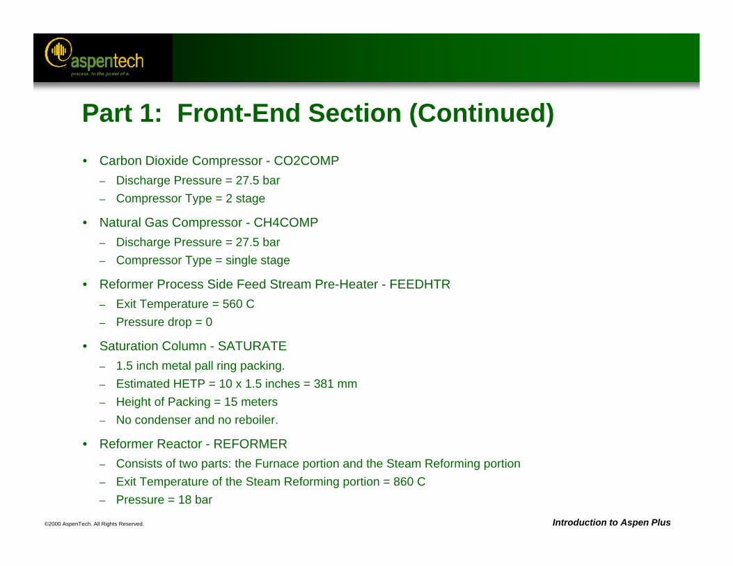
©2000 AspenTech. All Rights Reserved. Introduction to Aspen Plus
Part 1: Front-End Section (Continued)• Carbon Dioxide Compressor - CO2COMP
– Discharge Pressure = 27.5 bar– Compressor Type = 2 stage
• Natural Gas Compressor - CH4COMP– Discharge Pressure = 27.5 bar– Compressor Type = single stage
• Reformer Process Side Feed Stream Pre-Heater - FEEDHTR– Exit Temperature = 560 C– Pressure drop = 0
• Saturation Column - SATURATE– 1.5 inch metal pall ring packing.– Estimated HETP = 10 x 1.5 inches = 381 mm– Height of Packing = 15 meters– No condenser and no reboiler.
• Reformer Reactor - REFORMER– Consists of two parts: the Furnace portion and the Steam Reforming portion– Exit Temperature of the Steam Reforming portion = 860 C– Pressure = 18 bar
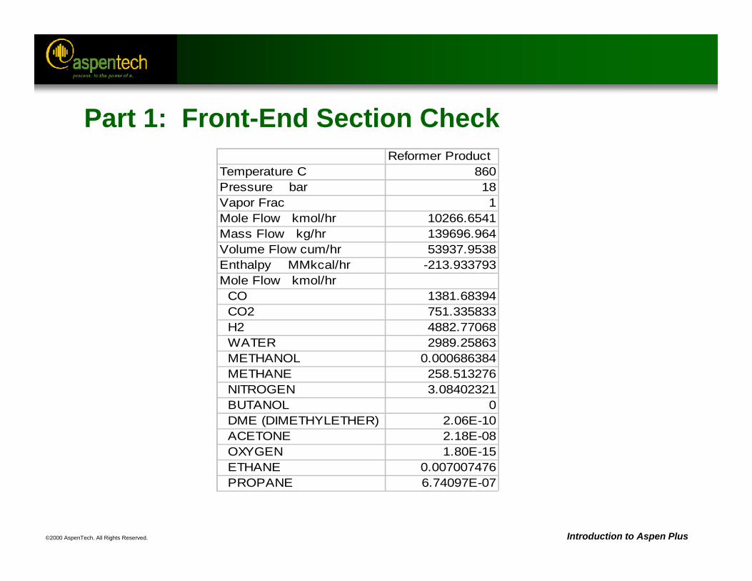
©2000 AspenTech. All Rights Reserved. Introduction to Aspen Plus
Part 1: Front-End Section Check Reformer ProductTemperature C 860Pressure bar 18Vapor Frac 1Mole Flow kmol/hr 10266.6541Mass Flow kg/hr 139696.964Volume Flow cum/hr 53937.9538Enthalpy MMkcal/hr -213.933793Mole Flow kmol/hr CO 1381.68394 CO2 751.335833 H2 4882.77068 WATER 2989.25863 METHANOL 0.000686384 METHANE 258.513276 NITROGEN 3.08402321 BUTANOL 0 DME (DIMETHYLETHER) 2.06E-10 ACETONE 2.18E-08 OXYGEN 1.80E-15 ETHANE 0.007007476 PROPANE 6.74097E-07
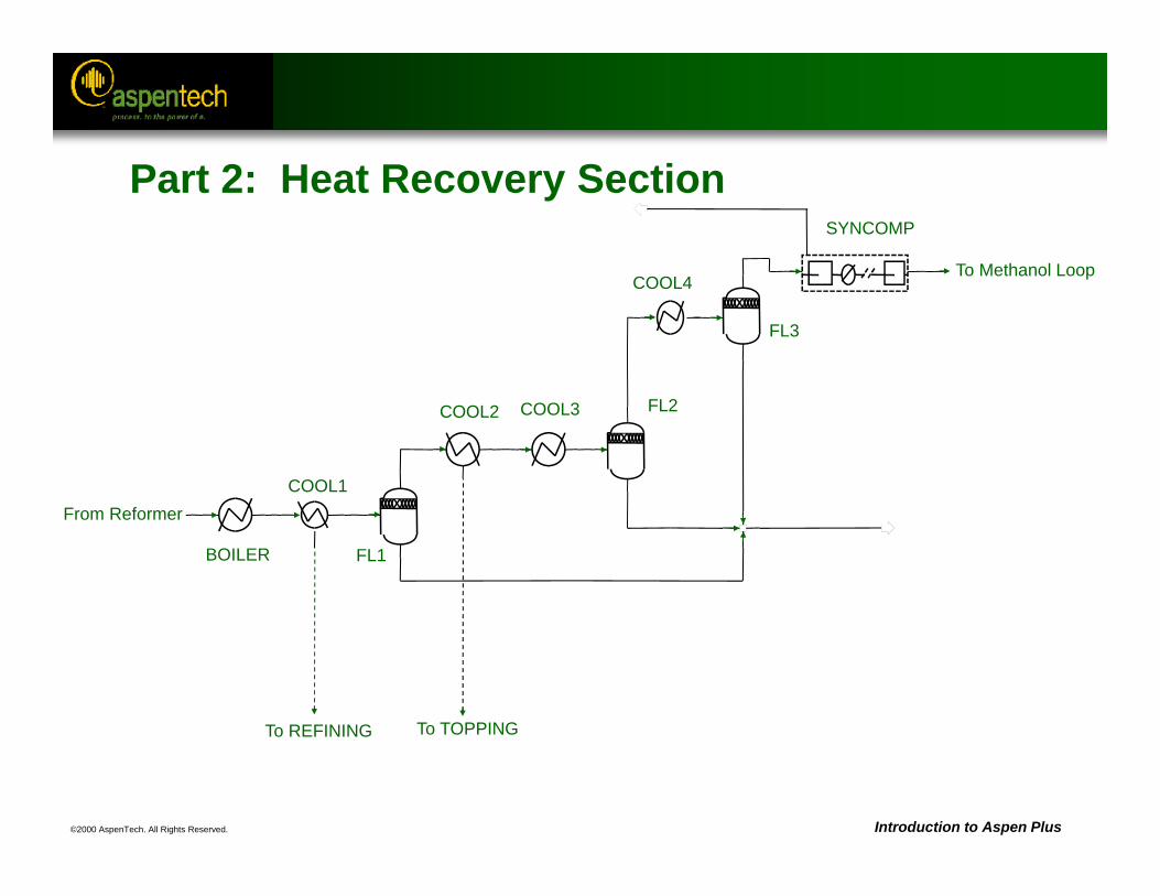
©2000 AspenTech. All Rights Reserved. Introduction to Aspen Plus
COOL4
FL3
SYNCOMP
FL1
FL2
COOL1
COOL3COOL2
BOILER
To TOPPINGTo REFINING
To Methanol Loop
From Reformer
Part 2: Heat Recovery Section
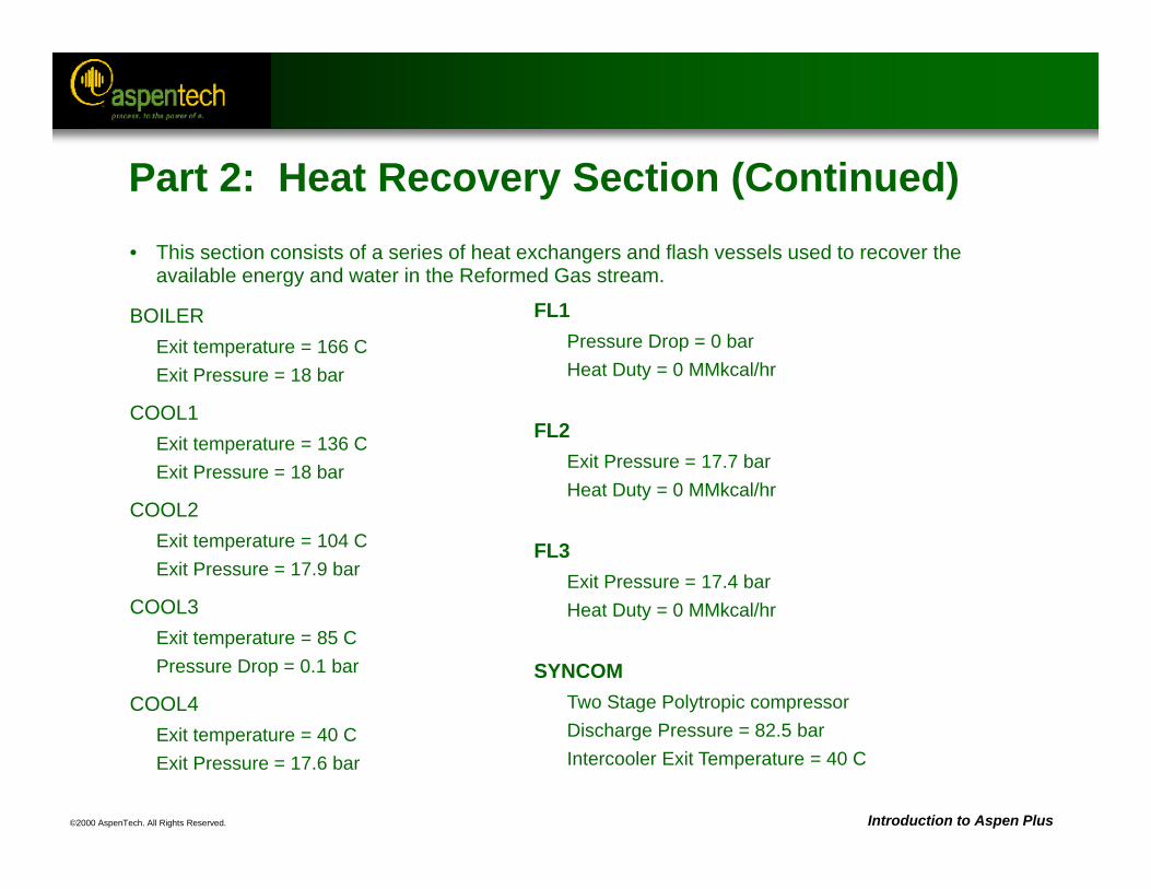
©2000 AspenTech. All Rights Reserved. Introduction to Aspen Plus
FL1Pressure Drop = 0 barHeat Duty = 0 MMkcal/hr
FL2Exit Pressure = 17.7 barHeat Duty = 0 MMkcal/hr
FL3Exit Pressure = 17.4 barHeat Duty = 0 MMkcal/hr
SYNCOMTwo Stage Polytropic compressorDischarge Pressure = 82.5 barIntercooler Exit Temperature = 40 C
Part 2: Heat Recovery Section (Continued)• This section consists of a series of heat exchangers and flash vessels used to recover the
available energy and water in the Reformed Gas stream.
BOILERExit temperature = 166 CExit Pressure = 18 bar
COOL1Exit temperature = 136 CExit Pressure = 18 bar
COOL2Exit temperature = 104 CExit Pressure = 17.9 bar
COOL3Exit temperature = 85 CPressure Drop = 0.1 bar
COOL4Exit temperature = 40 CExit Pressure = 17.6 bar
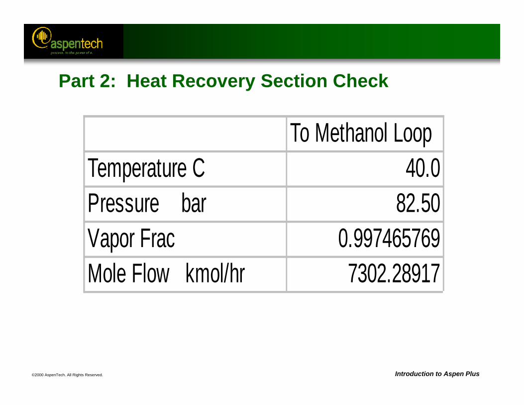
©2000 AspenTech. All Rights Reserved. Introduction to Aspen Plus
To Methanol LoopTemperature C 40.0Pressure bar 82.50Vapor Frac 0.997465769Mole Flow kmol/hr 7302.28917
Part 2: Heat Recovery Section Check
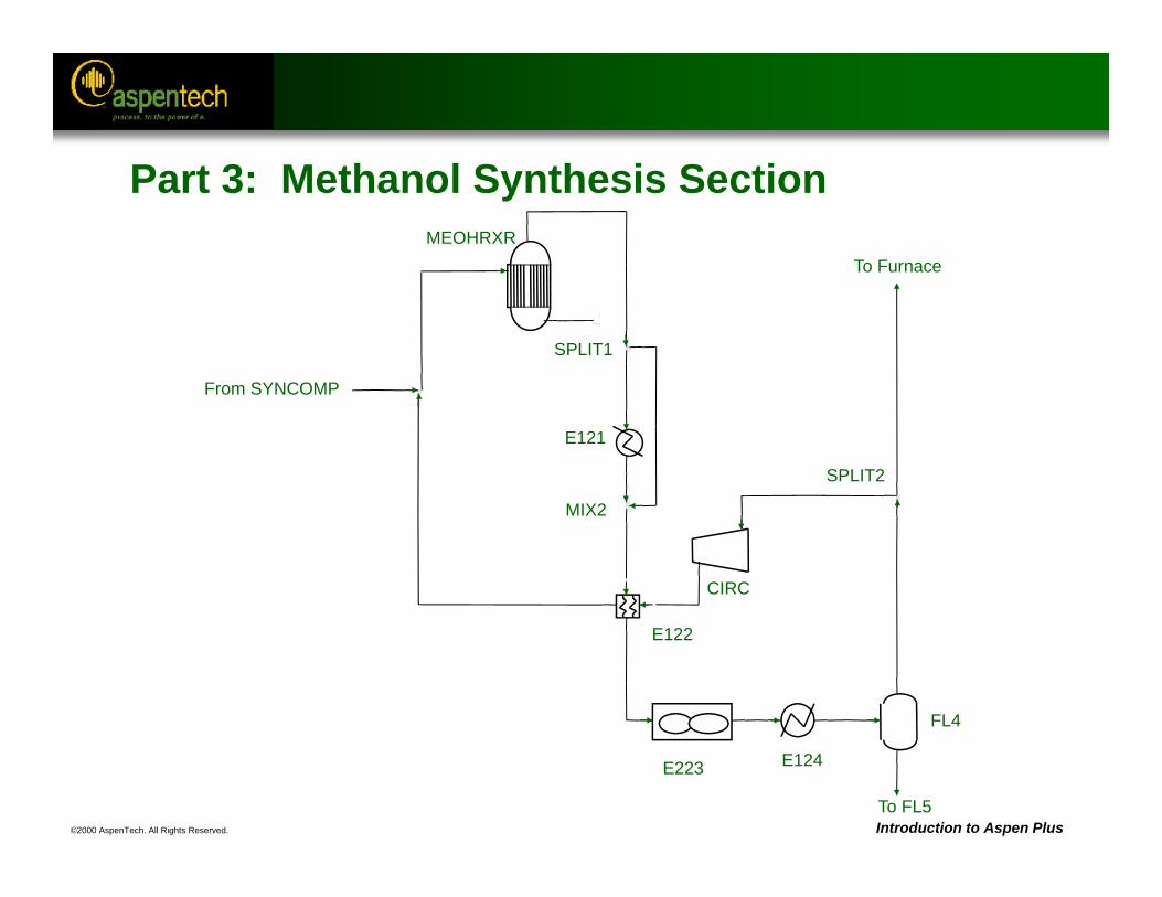
©2000 AspenTech. All Rights Reserved. Introduction to Aspen Plus
MEOHRXR
SPLIT1
MIX2
E121
From SYNCOMP
E122
CIRC
E124E223
FL4
SPLIT2
To Furnace
To FL5
Part 3: Methanol Synthesis Section
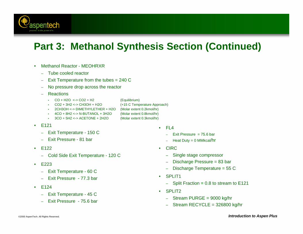
©2000 AspenTech. All Rights Reserved. Introduction to Aspen Plus
Part 3: Methanol Synthesis Section (Continued)
• Methanol Reactor - MEOHRXR– Tube cooled reactor– Exit Temperature from the tubes = 240 C– No pressure drop across the reactor– Reactions
• CO + H2O <-> CO2 + H2 (Equilibrium)• CO2 + 3H2 <-> CH3OH + H2O (+15 C Temperature Approach)• 2CH3OH <-> DIMETHYLETHER + H2O (Molar extent 0.2kmol/hr)• 4CO + 8H2 <-> N-BUTANOL + 3H2O (Molar extent 0.8kmol/hr)• 3CO + 5H2 <-> ACETONE + 2H2O (Molar extent 0.3kmol/hr)
• E121– Exit Temperature - 150 C– Exit Pressure - 81 bar
• E122– Cold Side Exit Temperature - 120 C
• E223– Exit Temperature - 60 C– Exit Pressure - 77.3 bar
• E124– Exit Temperature - 45 C– Exit Pressure - 75.6 bar
• FL4– Exit Pressure = 75.6 bar– Heat Duty = 0 MMkcal/hr
• CIRC – Single stage compressor– Discharge Pressure = 83 bar– Discharge Temperature = 55 C
• SPLIT1 – Split Fraction = 0.8 to stream to E121
• SPLIT2– Stream PURGE = 9000 kg/hr– Stream RECYCLE = 326800 kg/hr
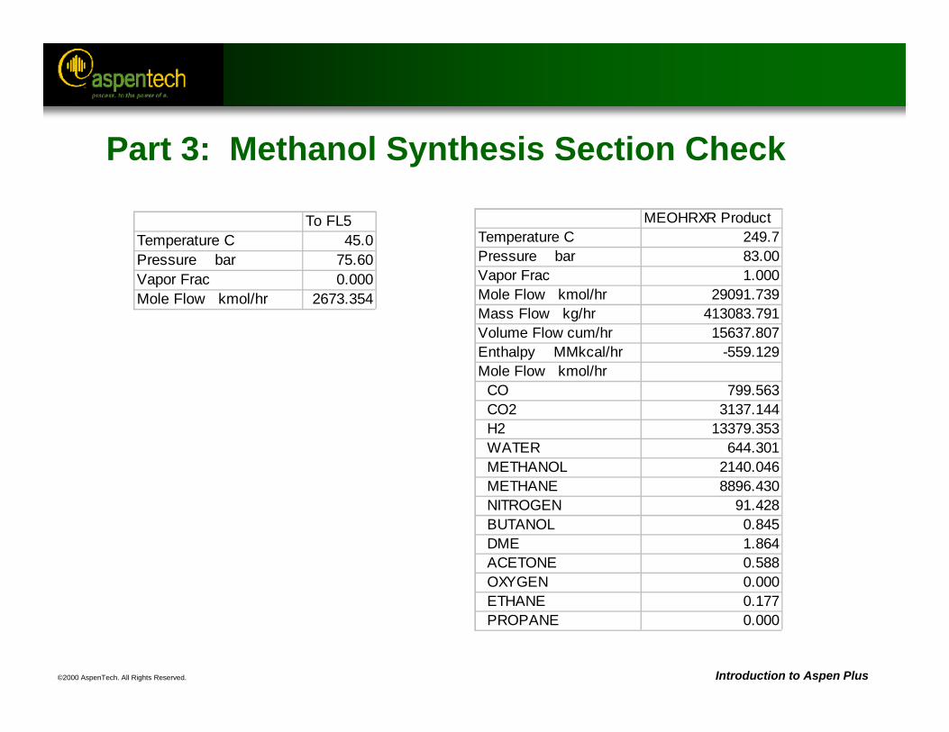
©2000 AspenTech. All Rights Reserved. Introduction to Aspen Plus
Part 3: Methanol Synthesis Section Check
To FL5Temperature C 45.0Pressure bar 75.60Vapor Frac 0.000Mole Flow kmol/hr 2673.354
MEOHRXR ProductTemperature C 249.7Pressure bar 83.00Vapor Frac 1.000Mole Flow kmol/hr 29091.739Mass Flow kg/hr 413083.791Volume Flow cum/hr 15637.807Enthalpy MMkcal/hr -559.129Mole Flow kmol/hr CO 799.563 CO2 3137.144 H2 13379.353 WATER 644.301 METHANOL 2140.046 METHANE 8896.430 NITROGEN 91.428 BUTANOL 0.845 DME 1.864 ACETONE 0.588 OXYGEN 0.000 ETHANE 0.177 PROPANE 0.000
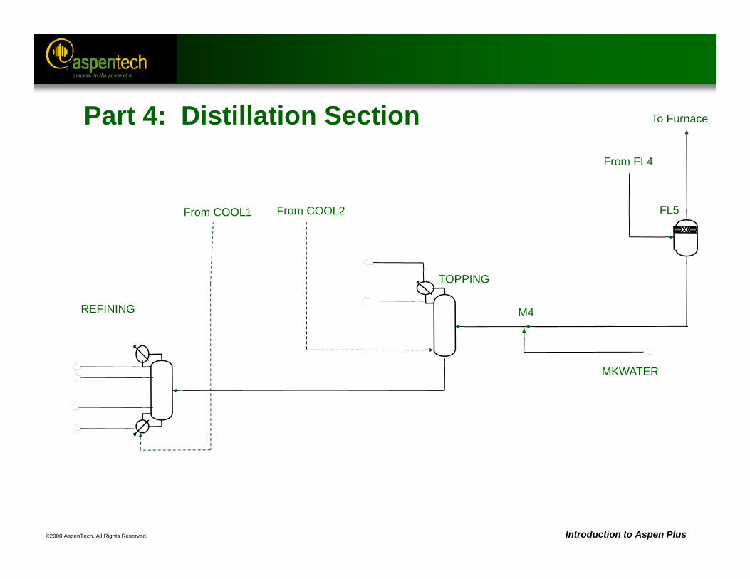
©2000 AspenTech. All Rights Reserved. Introduction to Aspen Plus
FL5
M4
MKWATER
TOPPING
REFINING
From COOL2
To Furnace
From COOL1
From FL4
Part 4: Distillation Section
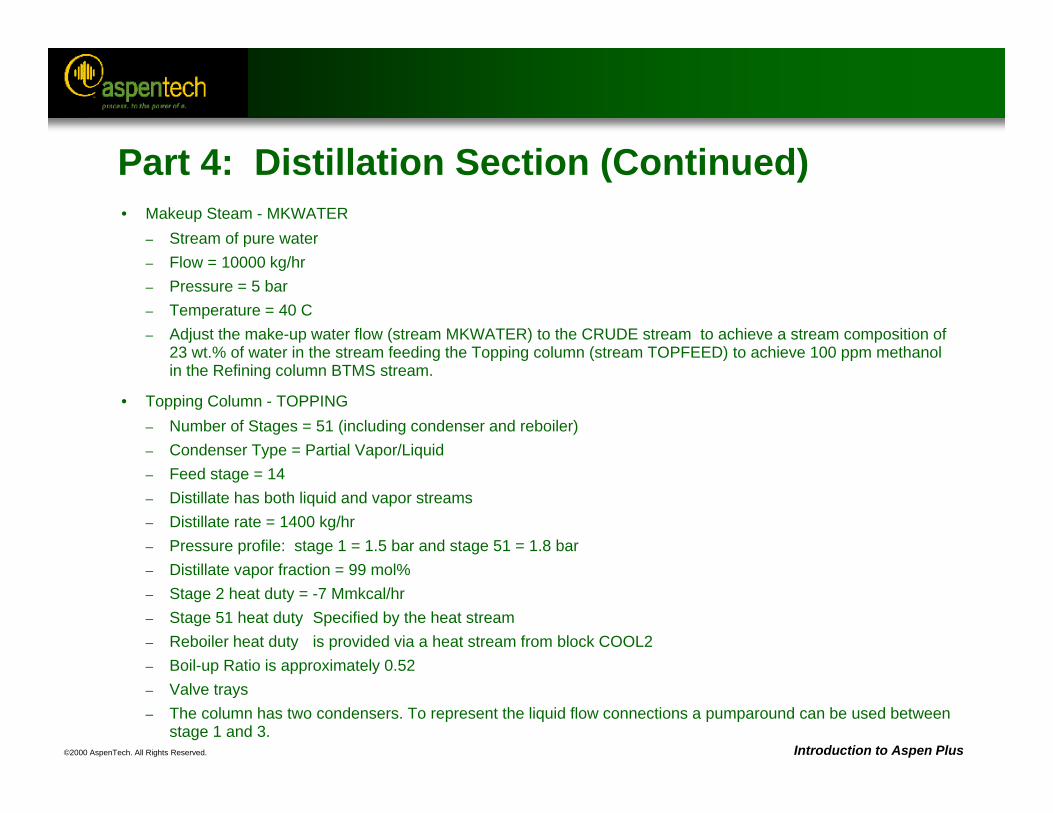
©2000 AspenTech. All Rights Reserved. Introduction to Aspen Plus
Part 4: Distillation Section (Continued)• Makeup Steam - MKWATER
– Stream of pure water– Flow = 10000 kg/hr– Pressure = 5 bar– Temperature = 40 C– Adjust the make-up water flow (stream MKWATER) to the CRUDE stream to achieve a stream composition of
23 wt.% of water in the stream feeding the Topping column (stream TOPFEED) to achieve 100 ppm methanol in the Refining column BTMS stream.
• Topping Column - TOPPING– Number of Stages = 51 (including condenser and reboiler)– Condenser Type = Partial Vapor/Liquid– Feed stage = 14– Distillate has both liquid and vapor streams– Distillate rate = 1400 kg/hr– Pressure profile: stage 1 = 1.5 bar and stage 51 = 1.8 bar– Distillate vapor fraction = 99 mol%– Stage 2 heat duty = -7 Mmkcal/hr– Stage 51 heat duty Specified by the heat stream– Reboiler heat duty is provided via a heat stream from block COOL2– Boil-up Ratio is approximately 0.52– Valve trays– The column has two condensers. To represent the liquid flow connections a pumparound can be used between
stage 1 and 3.
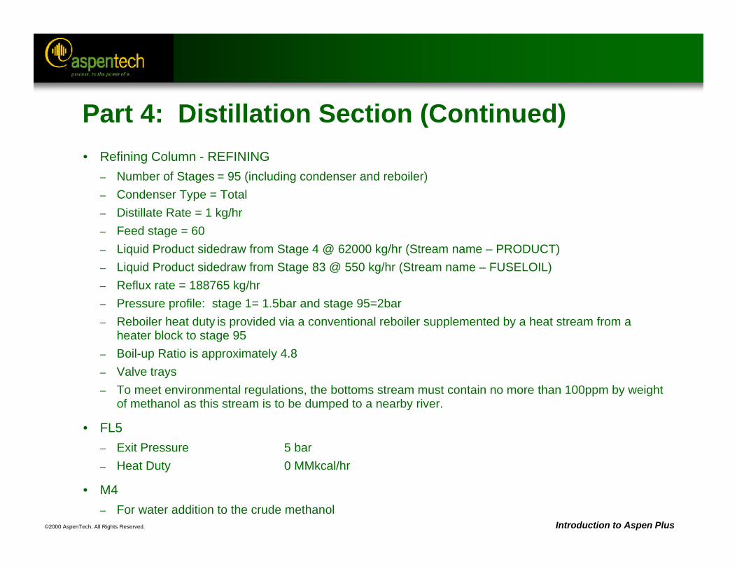
©2000 AspenTech. All Rights Reserved. Introduction to Aspen Plus
Part 4: Distillation Section (Continued)• Refining Column - REFINING
– Number of Stages = 95 (including condenser and reboiler)– Condenser Type = Total– Distillate Rate = 1 kg/hr– Feed stage = 60– Liquid Product sidedraw from Stage 4 @ 62000 kg/hr (Stream name – PRODUCT)– Liquid Product sidedraw from Stage 83 @ 550 kg/hr (Stream name – FUSELOIL)– Reflux rate = 188765 kg/hr– Pressure profile: stage 1= 1.5bar and stage 95=2bar– Reboiler heat duty is provided via a conventional reboiler supplemented by a heat stream from a
heater block to stage 95– Boil-up Ratio is approximately 4.8– Valve trays– To meet environmental regulations, the bottoms stream must contain no more than 100ppm by weight
of methanol as this stream is to be dumped to a nearby river.
• FL5– Exit Pressure 5 bar– Heat Duty 0 MMkcal/hr
• M4 – For water addition to the crude methanol
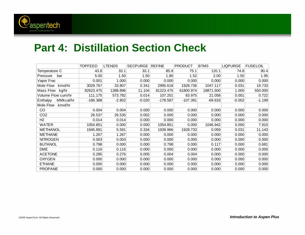
©2000 AspenTech. All Rights Reserved. Introduction to Aspen Plus
Part 4: Distillation Section Check TOPFEED LTENDS SECPURGE REFINE PRODUCT BTMS LIQPURGE FUSELOILTemperature C 43.8 33.1 33.1 85.8 75.1 120.1 74.8 90.4Pressure bar 5.00 1.50 1.50 1.80 1.52 2.00 1.50 1.95Vapor Frac 0.001 1.000 0.000 0.000 0.000 0.000 0.000 0.000Mole Flow kmol/hr 3029.767 33.807 0.341 2995.618 1928.736 1047.117 0.031 19.733Mass Flow kg/hr 82623.475 1388.896 11.104 81223.475 61800.974 18871.500 1.000 550.000Volume Flow cum/hr 111.175 573.782 0.014 107.201 83.975 21.058 0.001 0.722Enthalpy MMkcal/hr -186.388 -2.802 -0.020 -178.587 -107.391 -69.633 -0.002 -1.199Mole Flow kmol/hr CO 0.004 0.004 0.000 0.000 0.000 0.000 0.000 0.000 CO2 26.537 26.535 0.002 0.000 0.000 0.000 0.000 0.000 H2 0.014 0.014 0.000 0.000 0.000 0.000 0.000 0.000 WATER 1054.851 0.000 0.000 1054.851 0.000 1046.942 0.000 7.910 METHANOL 1945.891 5.591 0.334 1939.966 1928.733 0.059 0.031 11.143 METHANE 1.267 1.267 0.000 0.000 0.000 0.000 0.000 0.000 NITROGEN 0.003 0.003 0.000 0.000 0.000 0.000 0.000 0.000 BUTANOL 0.798 0.000 0.000 0.798 0.000 0.117 0.000 0.681 DME 0.116 0.116 0.000 0.000 0.000 0.000 0.000 0.000 ACETONE 0.285 0.276 0.005 0.004 0.004 0.000 0.000 0.000 OXYGEN 0.000 0.000 0.000 0.000 0.000 0.000 0.000 0.000 ETHANE 0.000 0.000 0.000 0.000 0.000 0.000 0.000 0.000 PROPANE 0.000 0.000 0.000 0.000 0.000 0.000 0.000 0.000
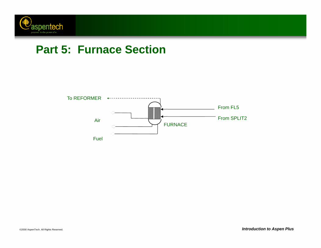
©2000 AspenTech. All Rights Reserved. Introduction to Aspen Plus
FURNACE
Fuel
Air
From FL5
From SPLIT2
To REFORMER
Part 5: Furnace Section
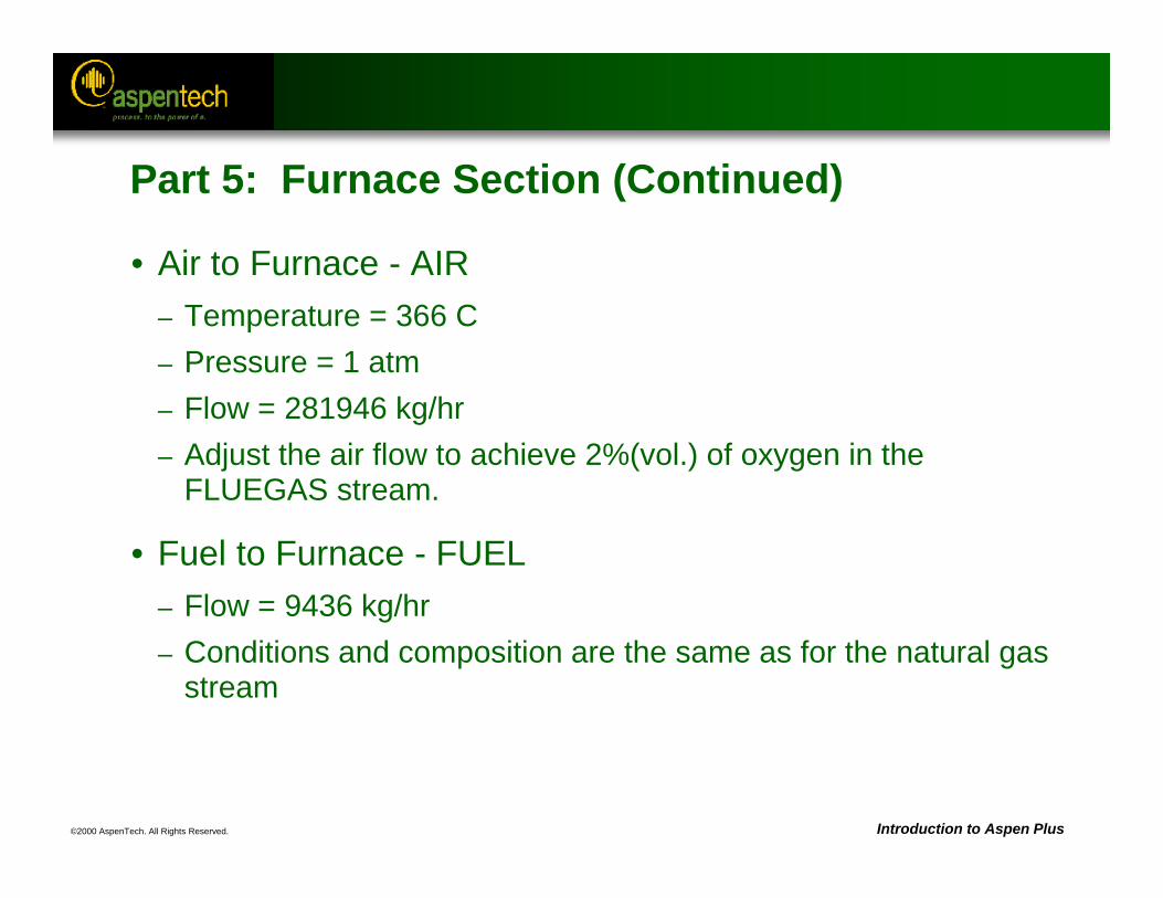
©2000 AspenTech. All Rights Reserved. Introduction to Aspen Plus
Part 5: Furnace Section (Continued)
• Air to Furnace - AIR– Temperature = 366 C– Pressure = 1 atm– Flow = 281946 kg/hr – Adjust the air flow to achieve 2%(vol.) of oxygen in the
FLUEGAS stream.
• Fuel to Furnace - FUEL– Flow = 9436 kg/hr– Conditions and composition are the same as for the natural gas
stream
©2000 AspenTech. All Rights Reserved.
Maintaining Aspen Plus Simulations
Objective:Introduce how to store simulations and retrieve
them from your computer environment
Aspen Plus References:User Guide, Chapter 15, Managing Your Files
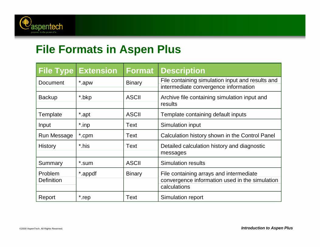
©2000 AspenTech. All Rights Reserved. Introduction to Aspen Plus
File Formats in Aspen Plus
File Type Extension Format DescriptionDocument *.apw Binary File containing simulation input and results and
intermediate convergence information
Backup *.bkp ASCII Archive file containing simulation input andresults
Template *.apt ASCII Template containing default inputs
Input *.inp Text Simulation input
Run Message *.cpm Text Calculation history shown in the Control Panel
History *.his Text Detailed calculation history and diagnosticmessages
Summary *.sum ASCII Simulation results
ProblemDefinition
*.appdf Binary File containing arrays and intermediateconvergence information used in the simulationcalculations
Report *.rep Text Simulation report
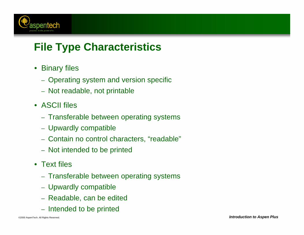
©2000 AspenTech. All Rights Reserved. Introduction to Aspen Plus
File Type Characteristics
• Binary files– Operating system and version specific– Not readable, not printable
• ASCII files– Transferable between operating systems– Upwardly compatible– Contain no control characters, “readable”– Not intended to be printed
• Text files– Transferable between operating systems– Upwardly compatible– Readable, can be edited– Intended to be printed
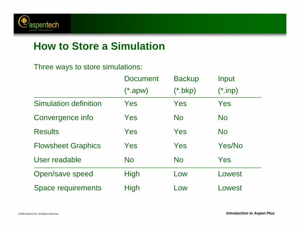
©2000 AspenTech. All Rights Reserved. Introduction to Aspen Plus
How to Store a Simulation
Three ways to store simulations:Document Backup Input(*.apw) (*.bkp) (*.inp)
Simulation definition Yes Yes Yes
Convergence info Yes No No
Results Yes Yes No
Flowsheet Graphics Yes Yes Yes/No
User readable No No Yes
Open/save speed High Low Lowest
Space requirements High Low Lowest
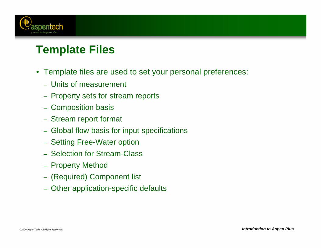
©2000 AspenTech. All Rights Reserved. Introduction to Aspen Plus
Template Files
• Template files are used to set your personal preferences:– Units of measurement– Property sets for stream reports– Composition basis– Stream report format– Global flow basis for input specifications– Setting Free-Water option– Selection for Stream-Class– Property Method– (Required) Component list– Other application-specific defaults
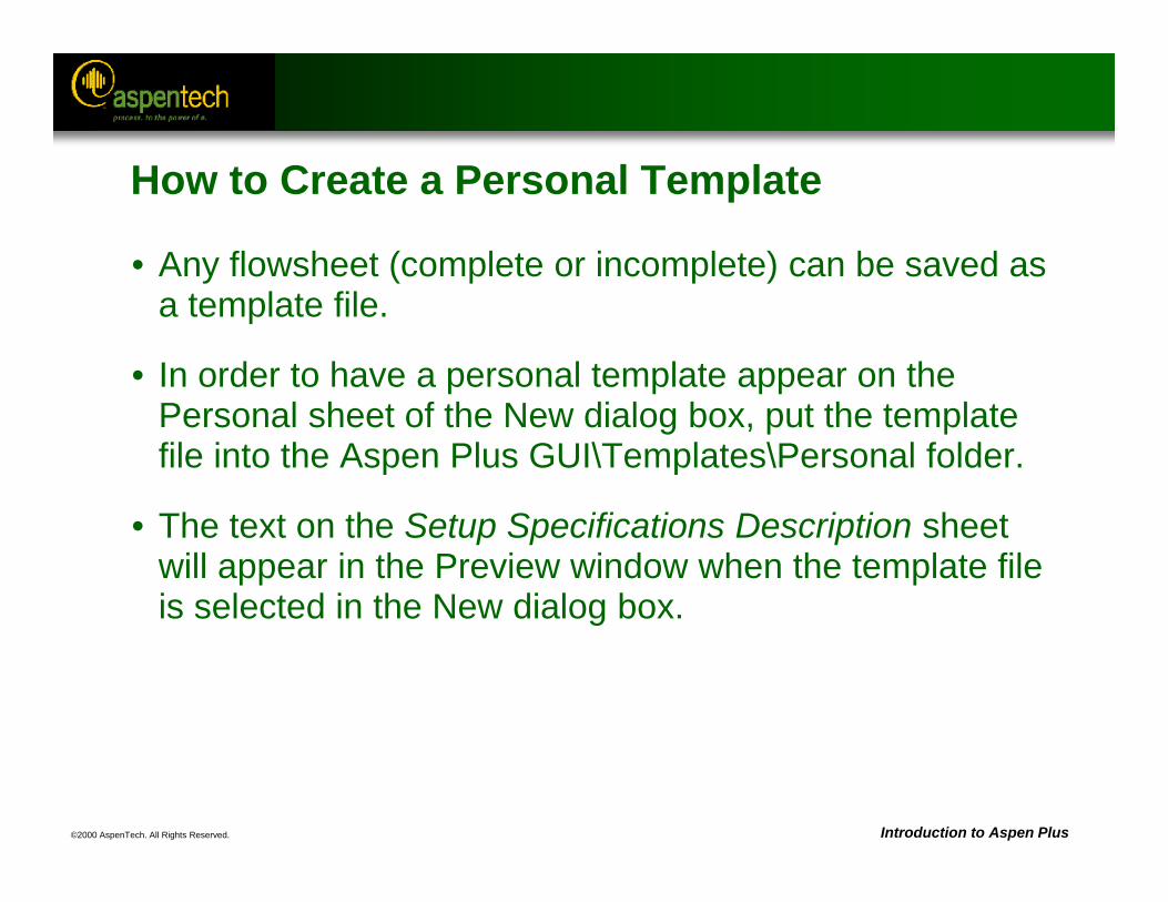
©2000 AspenTech. All Rights Reserved. Introduction to Aspen Plus
How to Create a Personal Template
• Any flowsheet (complete or incomplete) can be saved as a template file.
• In order to have a personal template appear on the Personal sheet of the New dialog box, put the template file into the Aspen Plus GUI\Templates\Personal folder.
• The text on the Setup Specifications Description sheet will appear in the Preview window when the template file is selected in the New dialog box.
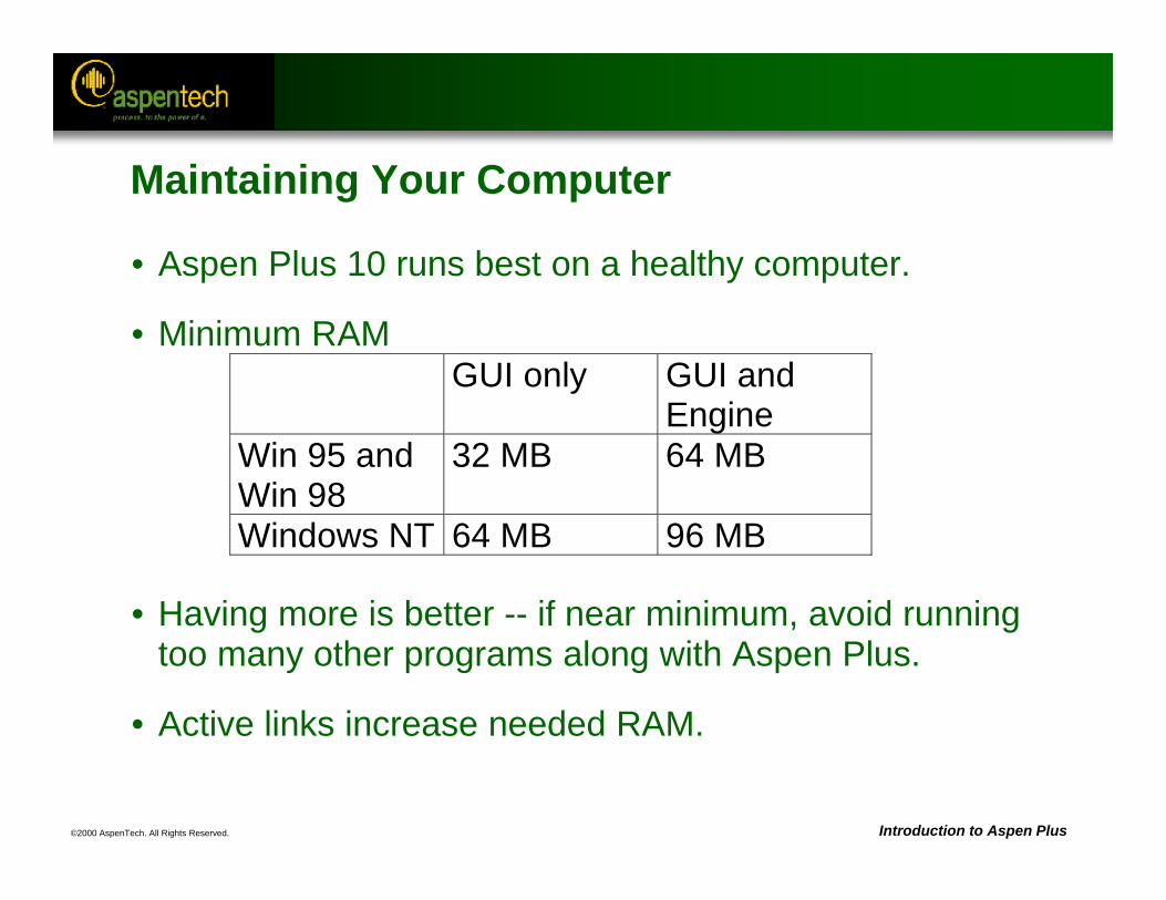
©2000 AspenTech. All Rights Reserved. Introduction to Aspen Plus
• Aspen Plus 10 runs best on a healthy computer.
• Minimum RAM
• Having more is better -- if near minimum, avoid running too many other programs along with Aspen Plus.
• Active links increase needed RAM.
GUI only GUI andEngine
Win 95 andWin 98
32 MB 64 MB
Windows NT 64 MB 96 MB
Maintaining Your Computer
©2000 AspenTech. All Rights Reserved. Introduction to Aspen Plus
Maintaining Your Hard Disk
• Keep plenty of free space on disk used for:– Your Aspen working directory– Windows swap files
• Delete unneeded files:– Old .appdf, .his, etc.– Aspen document files (*.apw) that aren’t active– Aspen temporary files (_4404ydj.appdf, for example)
• Defragment regularly (once a week), even if Windows says you don’t need to -- make the free space contiguous.
©2000 AspenTech. All Rights Reserved.
Customizing the Look of Your Flowsheet
Objective:
Introduce several ways of annotating your flowsheet to create informative Process Flow Diagrams
Aspen Plus References:User Guide, Chapter 14, Annotating Process Flowsheets
Related Topics:User Guide, Chapter 37, Working with Other Windows Programs
©2000 AspenTech. All Rights Reserved. Introduction to Aspen Plus
Customizing the Process Flow Diagram
• Add annotations– Text– Graphics– Tables
• Add OLE objects– Add a titlebox– Add plots or diagrams
• Display global data– Stream flowrate, pressure and
temperature– Heat stream duty– Work stream power– Block duty and power
• Use PFD mode– Change flowsheet connectivity
©2000 AspenTech. All Rights Reserved. Introduction to Aspen Plus
Viewing
• Use the View menu to select the elements that you wish to view:– PFD Mode – Global Data– Annotation– OLE Objects
• All of the elements can be turned on and off independently.
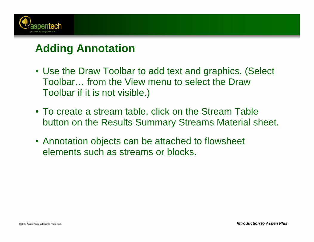
©2000 AspenTech. All Rights Reserved. Introduction to Aspen Plus
Adding Annotation
• Use the Draw Toolbar to add text and graphics. (Select Toolbar… from the View menu to select the Draw Toolbar if it is not visible.)
• To create a stream table, click on the Stream Table button on the Results Summary Streams Material sheet.
• Annotation objects can be attached to flowsheet elements such as streams or blocks.
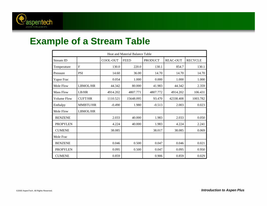
©2000 AspenTech. All Rights Reserved. Introduction to Aspen Plus
Heat and Material Balance Table
Stream ID COOL-OUT FEED PRODUCT REAC-OUT RECYCLE
Temperature F 130.0 220.0 130.1 854.7 130.1
Pressure PSI 14.60 36.00 14.70 14.70 14.70
Vapor Frac 0.054 1.000 0.000 1.000 1.000
Mole Flow LBMOL/HR 44.342 80.000 41.983 44.342 2.359
Mass Flow LB/HR 4914.202 4807.771 4807.772 4914.202 106.431
Volume Flow CUFT/HR 1110.521 15648.095 93.470 42338.408 1003.782
Enthalpy MMBTU/HR -0.490 1.980 -0.513 2.003 0.023
Mole Flow LBMOL/HR
BENZENE 2.033 40.000 1.983 2.033 0.050
PROPYLEN 4.224 40.000 1.983 4.224 2.241
CUMENE 38.085 38.017 38.085 0.069
Mole Frac
BENZENE 0.046 0.500 0.047 0.046 0.021
PROPYLEN 0.095 0.500 0.047 0.095 0.950
CUMENE 0.859 0.906 0.859 0.029
Example of a Stream Table
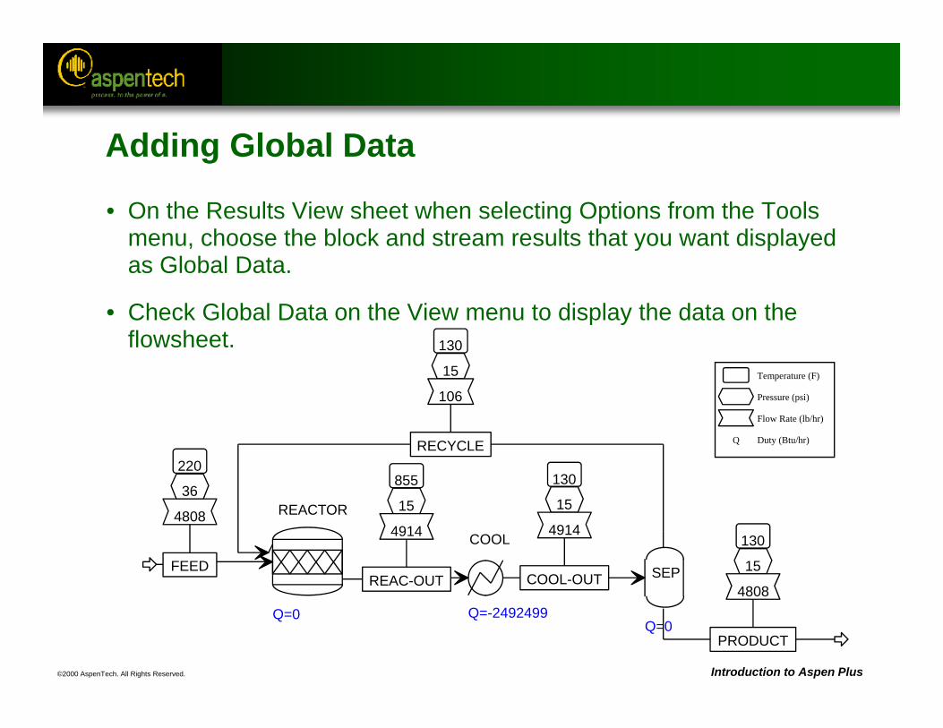
©2000 AspenTech. All Rights Reserved. Introduction to Aspen Plus
Temperature (F)
Pressure (psi)
Flow Rate (lb/hr)
Q Duty (Btu/hr)
REACTOR
Q=0
220
36
4808
FEED
130
15
106
RECYCLE
855
15
4914
REAC-OUT
COOL
Q=-2492499
130
15
4914
COOL-OUT SEP
Q=0
130
15
4808
PRODUCT
Adding Global Data
• On the Results View sheet when selecting Options from the Tools menu, choose the block and stream results that you want displayed as Global Data.
• Check Global Data on the View menu to display the data on the flowsheet.
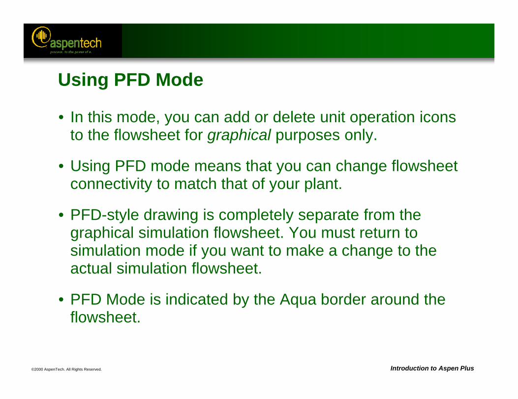
©2000 AspenTech. All Rights Reserved. Introduction to Aspen Plus
Using PFD Mode
• In this mode, you can add or delete unit operation icons to the flowsheet for graphical purposes only.
• Using PFD mode means that you can change flowsheet connectivity to match that of your plant.
• PFD-style drawing is completely separate from the graphical simulation flowsheet. You must return to simulation mode if you want to make a change to the actual simulation flowsheet.
• PFD Mode is indicated by the Aqua border around the flowsheet.
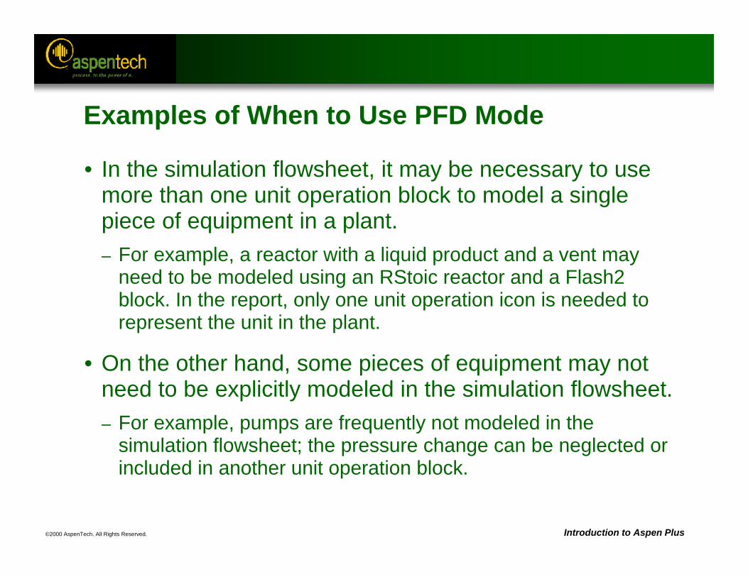
©2000 AspenTech. All Rights Reserved. Introduction to Aspen Plus
Examples of When to Use PFD Mode
• In the simulation flowsheet, it may be necessary to use more than one unit operation block to model a single piece of equipment in a plant. – For example, a reactor with a liquid product and a vent may
need to be modeled using an RStoic reactor and a Flash2 block. In the report, only one unit operation icon is needed to represent the unit in the plant.
• On the other hand, some pieces of equipment may not need to be explicitly modeled in the simulation flowsheet. – For example, pumps are frequently not modeled in the
simulation flowsheet; the pressure change can be neglected or included in another unit operation block.
©2000 AspenTech. All Rights Reserved. Introduction to Aspen Plus
Annotation Workshop
• Objective: Use annotation to create a process flow diagram for the cyclohexane flowsheet
• Part A– Using the cyclohexane production Workshop (saved as
CYCLOHEX.BKP), display all stream and block global data.
• Part B– Add a title to the flowsheet diagram.
• Part C– Add a stream table to the flowsheet diagram.
• Part D– Using PFD Mode, add a pump for the BZIN stream for graphical
purposes only.
©2000 AspenTech. All Rights Reserved.
Estimation of Physical Properties
Objective:
Provide an overview of estimating physical property parameters in Aspen Plus
Aspen Plus References: User Guide, Chapter 30, Estimating Property ParametersPhysical Property Methods and Models Reference Manual,
Chapter 8, Property Parameter Estimation
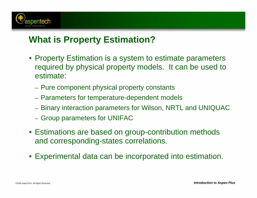
©2000 AspenTech. All Rights Reserved. Introduction to Aspen Plus
What is Property Estimation?
• Property Estimation is a system to estimate parameters required by physical property models. It can be used to estimate:– Pure component physical property constants– Parameters for temperature-dependent models– Binary interaction parameters for Wilson, NRTL and UNIQUAC– Group parameters for UNIFAC
• Estimations are based on group-contribution methods and corresponding-states correlations.
• Experimental data can be incorporated into estimation.
©2000 AspenTech. All Rights Reserved. Introduction to Aspen Plus
Using Property Estimation
• Property Estimation can be used in two ways:– On a stand-alone basis: Property Estimation Run Type– Within another Run Type: Flowsheet, Property Analysis, Data
Regression, PROPERTIES PLUS or Assay Data Analysis
• You can use Property Estimation to estimate properties for both databank and non-databank components.
• Property Estimation information is accessed in the Properties Estimation folder.
©2000 AspenTech. All Rights Reserved. Introduction to Aspen Plus
Estimation Methods and Requirements
• User Guide, Chapter 30, Estimating Property Parameters, has a complete list of properties that can be estimated, as well as the available estimation methods and their respective requirements.
• This same information is also available under the on-line help in the estimation forms.
©2000 AspenTech. All Rights Reserved. Introduction to Aspen Plus
Steps For Using Property Estimation
1. Define molecular structure on the Properties Molecular Structure form.
2. Enter any experimental data using Parameters or Data forms.– Experimental data such as normal boiling point (TB) is very
important for many estimation methods. It should be entered whenever possible.
3. Activate Property Estimation and choose property estimation options on the Properties Estimation Inputform.
©2000 AspenTech. All Rights Reserved. Introduction to Aspen Plus
Defining Molecular Structure
• Molecular structure is required for all group-contribution methods used in Property Estimation. You can:– Define molecular structure in the general format and allow
Aspen Plus to determine functional groups,or
– Define molecular structure in terms of functional groups for particular methods
• Reference: For a list of available group-contribution method functional groups, see Aspen Plus Physical Property Data Reference Manual, Chapter 3, Group Contribution Method Functional Groups.
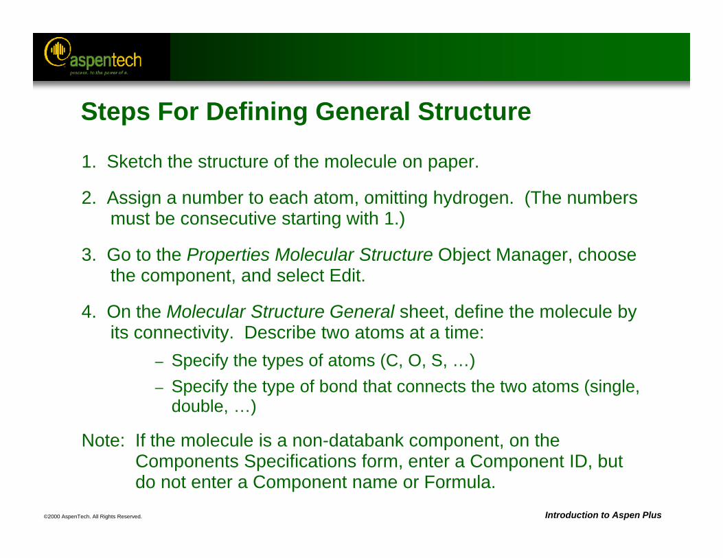
©2000 AspenTech. All Rights Reserved. Introduction to Aspen Plus
Steps For Defining General Structure
1. Sketch the structure of the molecule on paper.
2. Assign a number to each atom, omitting hydrogen. (The numbers must be consecutive starting with 1.)
3. Go to the Properties Molecular Structure Object Manager, choose the component, and select Edit.
4. On the Molecular Structure General sheet, define the molecule by its connectivity. Describe two atoms at a time:
– Specify the types of atoms (C, O, S, …) – Specify the type of bond that connects the two atoms (single,
double, …)
Note: If the molecule is a non-databank component, on the Components Specifications form, enter a Component ID, but do not enter a Component name or Formula.
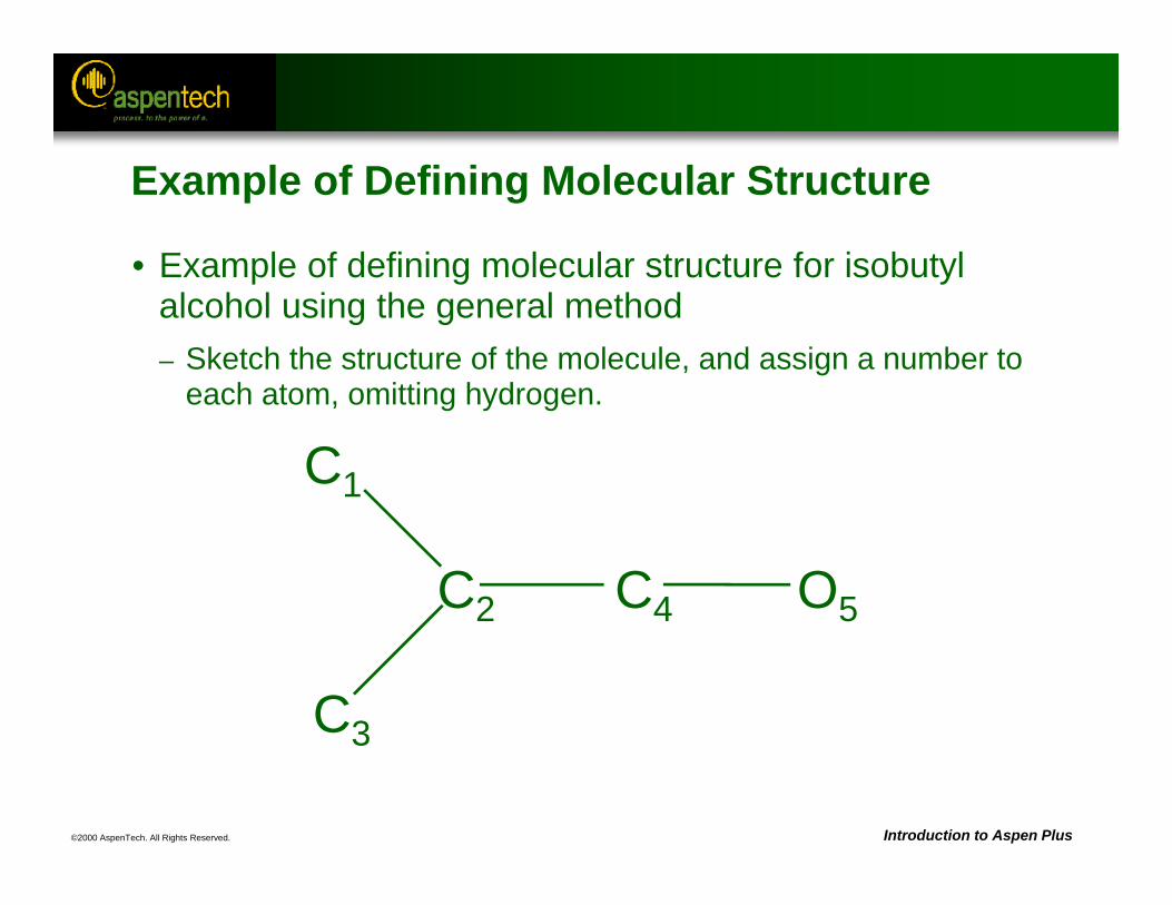
©2000 AspenTech. All Rights Reserved. Introduction to Aspen Plus
C2
C1
C4
C3
O5
Example of Defining Molecular Structure
• Example of defining molecular structure for isobutyl alcohol using the general method– Sketch the structure of the molecule, and assign a number to
each atom, omitting hydrogen.
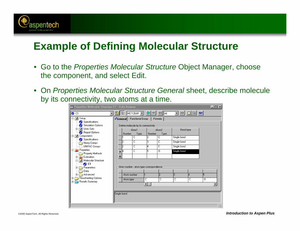
©2000 AspenTech. All Rights Reserved. Introduction to Aspen Plus
Example of Defining Molecular Structure
• Go to the Properties Molecular Structure Object Manager, choose the component, and select Edit.
• On Properties Molecular Structure General sheet, describe molecule by its connectivity, two atoms at a time.
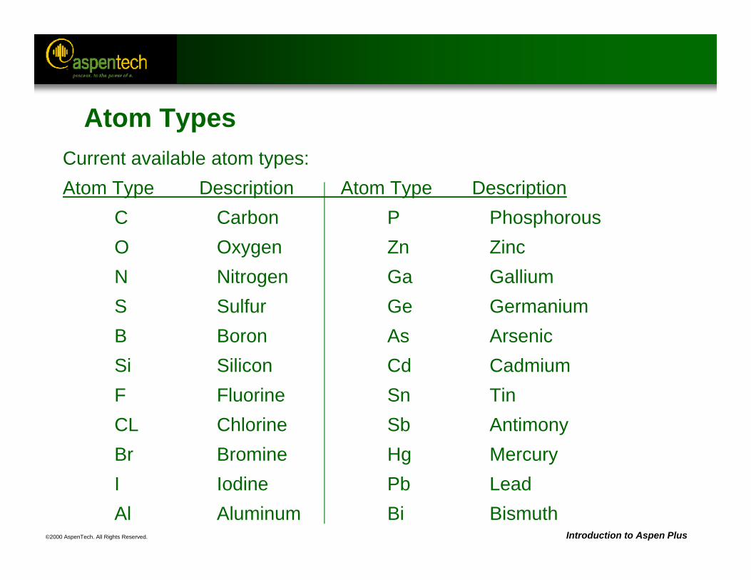
©2000 AspenTech. All Rights Reserved. Introduction to Aspen Plus
Atom TypesCurrent available atom types:Atom Type Description Atom Type Description
C Carbon P PhosphorousO Oxygen Zn ZincN Nitrogen Ga GalliumS Sulfur Ge GermaniumB Boron As ArsenicSi Silicon Cd CadmiumF Fluorine Sn TinCL Chlorine Sb AntimonyBr Bromine Hg MercuryI Iodine Pb LeadAl Aluminum Bi Bismuth
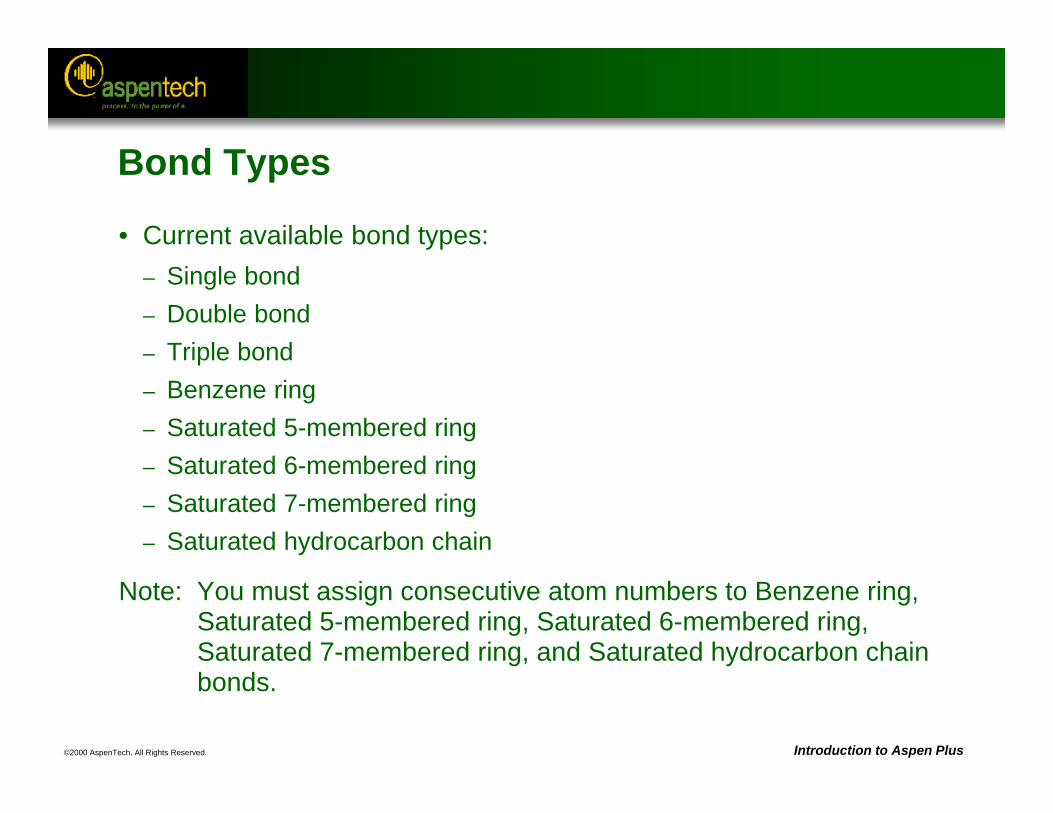
©2000 AspenTech. All Rights Reserved. Introduction to Aspen Plus
Bond Types
• Current available bond types:– Single bond– Double bond– Triple bond– Benzene ring– Saturated 5-membered ring– Saturated 6-membered ring– Saturated 7-membered ring– Saturated hydrocarbon chain
Note: You must assign consecutive atom numbers to Benzene ring, Saturated 5-membered ring, Saturated 6-membered ring, Saturated 7-membered ring, and Saturated hydrocarbon chain bonds.
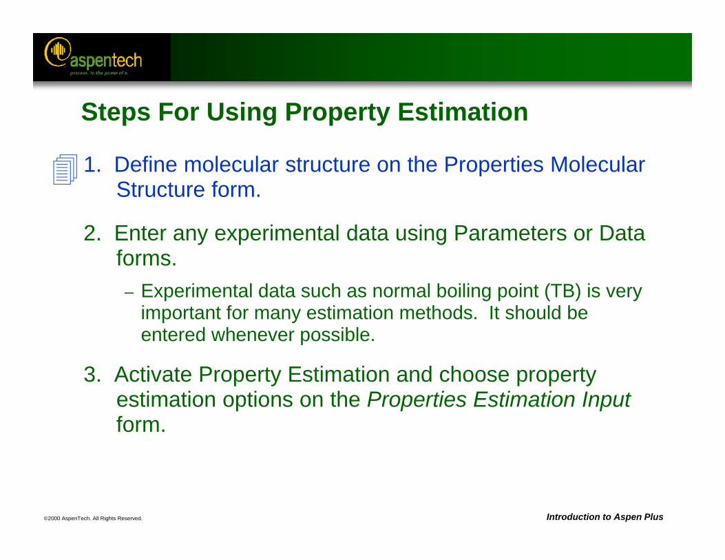
©2000 AspenTech. All Rights Reserved. Introduction to Aspen Plus
Steps For Using Property Estimation
1. Define molecular structure on the Properties Molecular Structure form.
2. Enter any experimental data using Parameters or Data forms.– Experimental data such as normal boiling point (TB) is very
important for many estimation methods. It should be entered whenever possible.
3. Activate Property Estimation and choose property estimation options on the Properties Estimation Inputform.
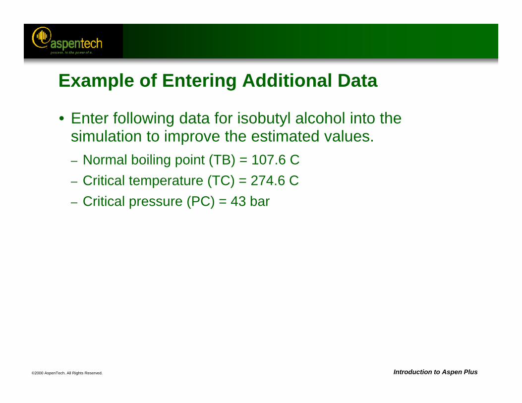
©2000 AspenTech. All Rights Reserved. Introduction to Aspen Plus
Example of Entering Additional Data
• Enter following data for isobutyl alcohol into the simulation to improve the estimated values. – Normal boiling point (TB) = 107.6 C– Critical temperature (TC) = 274.6 C– Critical pressure (PC) = 43 bar
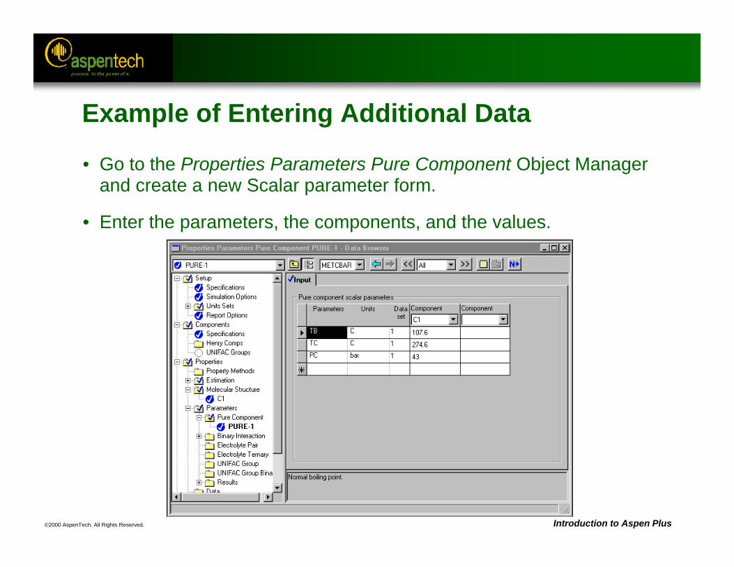
©2000 AspenTech. All Rights Reserved. Introduction to Aspen Plus
Example of Entering Additional Data
• Go to the Properties Parameters Pure Component Object Manager and create a new Scalar parameter form.
• Enter the parameters, the components, and the values.
©2000 AspenTech. All Rights Reserved. Introduction to Aspen Plus
Steps For Using Property Estimation
1. Define molecular structure on the Properties Molecular Structure form.
2. Enter any experimental data using Parameters or Data forms.– Experimental data such as normal boiling point (TB) is very
important for many estimation methods. It should be entered whenever possible.
3. Activate Property Estimation and choose property estimation options on the Properties Estimation
Input form.
©2000 AspenTech. All Rights Reserved. Introduction to Aspen Plus
Activating Property Estimation
• To turn on Property Estimation, go to the Properties Estimation Input Setup sheet, and select one of the following:– Estimate all missing parameters
• Estimates all missing required parameters and any parameters you may request in the optional Pure Component, T-Dependent, Binary, and UNIFAC-Group sheets
– Estimate only the selected parameters• Estimates on the parameter types you select on this sheet (and then
specify on the appropriate additional sheets)
©2000 AspenTech. All Rights Reserved. Introduction to Aspen Plus
Property Estimation Notes
• You can save your property data specifications, structures, and estimates as backup files, and import them into other simulations (Flowsheet, Data Regression, Property Analysis, or Assay Data Analysis Run-Types.)
• You can change the Run type on the Setup Specifications Global sheet to continue the simulation in the same file.
• If you want to change the Run type back to Property Estimation from another Run type, no flowsheet information is lost even though it may not be visible in the Property Estimation mode.
©2000 AspenTech. All Rights Reserved. Introduction to Aspen Plus
When finished, save asfilename: PCES.BKP
Property Estimation Workshop
• Objective: Estimate the properties of a dimer, ethycellosolve.
• Ethylcellosolve is not in any of the Aspen Plus databanks.
• Use a Run Type of Property Estimation, and estimate the properties for the new component.
• The formula for the component is shown below, along with the normal boiling point obtained from literature.Formula: CH3 - CH2 - O - CH2 - CH2 - O - CH2 - CH2 - OH TB = 195 C
©2000 AspenTech. All Rights Reserved. Introduction to Aspen Plus
Property Estimation Workshop (Continued)
1. Use a Run Type of Property Estimation and enter the structure and data for the Dimer.
2. Run the estimation, and examine the results.– Note that the results of the estimation are automatically
written to parameters forms, for use in other simulations.
3. Change the Run Type back to Flowsheet.
4. Go to the Properties Estimation Input Setup sheet, and choose Do not estimate any parameters.
5. Optionally, add a flowsheet and use this component.

©2000 AspenTech. All Rights Reserved.
Electrolytes
Objective:
Introduce the electrolyte capabilities in Aspen Plus
Aspen Plus References:User Guide, Chapter 6, Specifying ComponentsPhysical Property Methods and Models Reference Manual, Chapter 5, Electrolyte Simulation
©2000 AspenTech. All Rights Reserved. Introduction to Aspen Plus
Electrolytes Examples
• Solutions with acids, bases or salts
• Sour water solutions
• Aqueous amines or hot carbonate for gas sweetening
©2000 AspenTech. All Rights Reserved. Introduction to Aspen Plus
Characteristics of an Electrolyte System
• Some molecular species dissociate partially or completely into ions in a liquid solvent
• Liquid phase reactions are always at chemical equilibrium
• Presence of ions in the liquid phase requires non-ideal solution thermodynamics
• Possible salt precipitation
©2000 AspenTech. All Rights Reserved. Introduction to Aspen Plus
Types of Components
• Solvents - Standard molecular species– Water– Methanol– Acetic Acid
• Soluble Gases - Henry’s Law components– Nitrogen– Oxygen– Carbon Dioxide
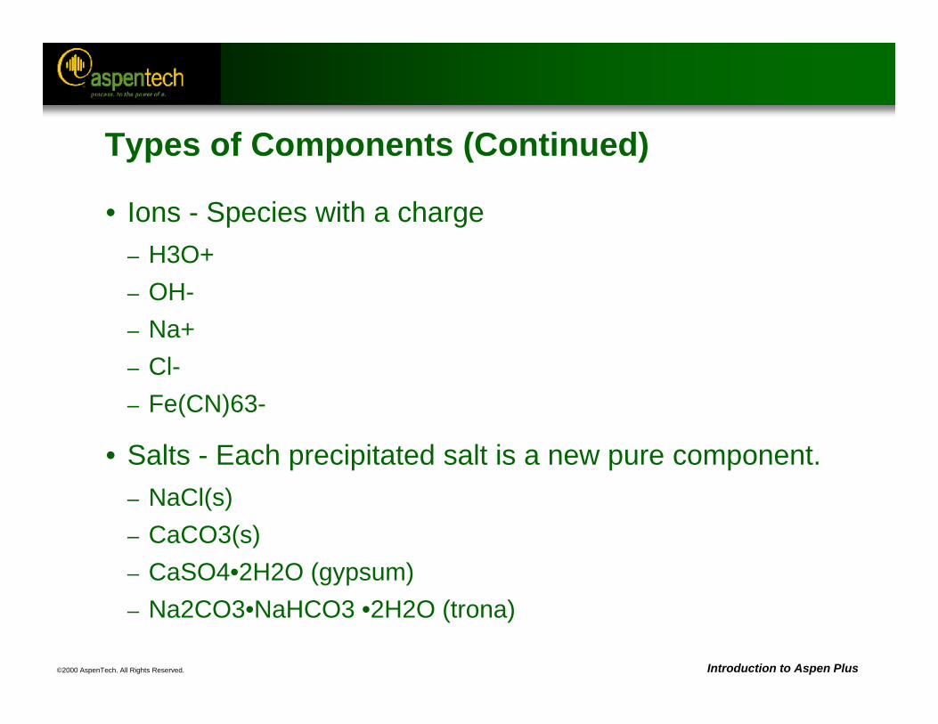
©2000 AspenTech. All Rights Reserved. Introduction to Aspen Plus
Types of Components (Continued)
• Ions - Species with a charge– H3O+– OH-– Na+– Cl-– Fe(CN)63-
• Salts - Each precipitated salt is a new pure component.– NaCl(s)– CaCO3(s)– CaSO4•2H2O (gypsum) – Na2CO3•NaHCO3 •2H2O (trona)
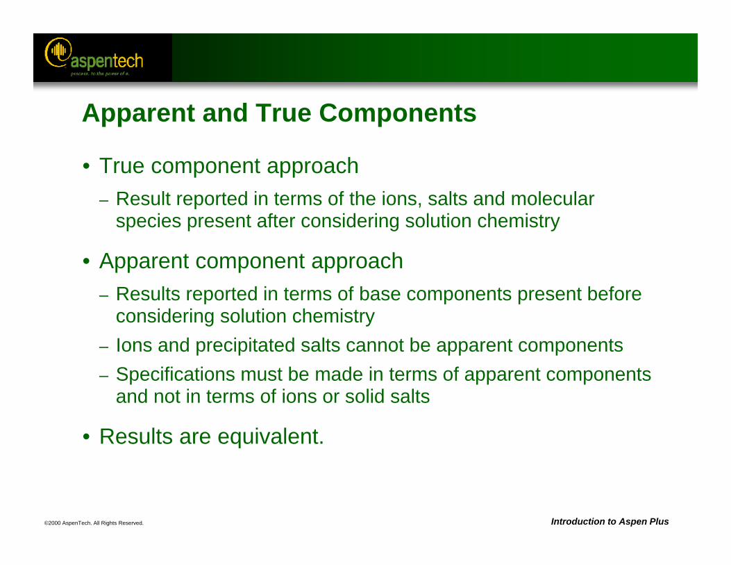
©2000 AspenTech. All Rights Reserved. Introduction to Aspen Plus
Apparent and True Components
• True component approach– Result reported in terms of the ions, salts and molecular
species present after considering solution chemistry
• Apparent component approach– Results reported in terms of base components present before
considering solution chemistry– Ions and precipitated salts cannot be apparent components– Specifications must be made in terms of apparent components
and not in terms of ions or solid salts
• Results are equivalent.
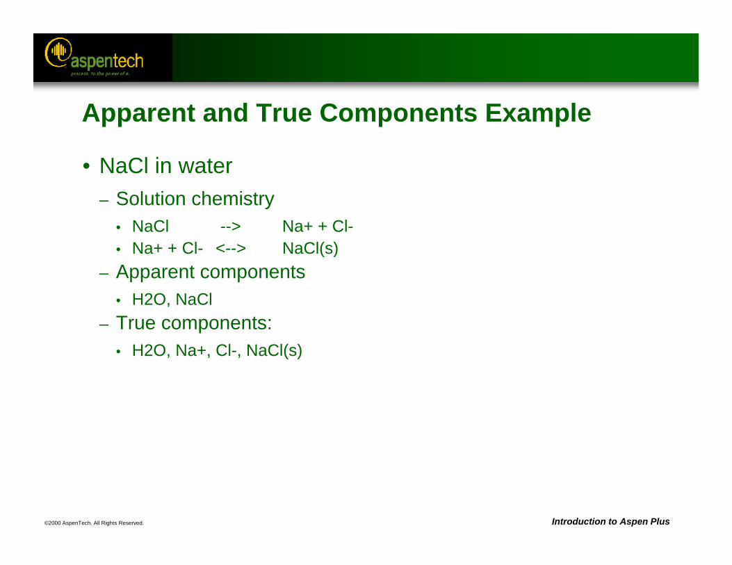
©2000 AspenTech. All Rights Reserved. Introduction to Aspen Plus
Apparent and True Components Example
• NaCl in water– Solution chemistry
• NaCl --> Na+ + Cl-• Na+ + Cl- <--> NaCl(s)
– Apparent components• H2O, NaCl
– True components:• H2O, Na+, Cl-, NaCl(s)
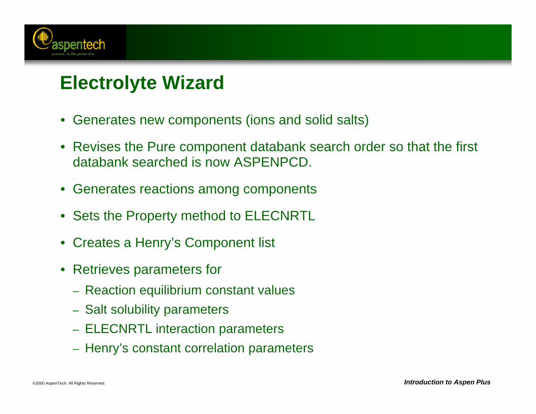
©2000 AspenTech. All Rights Reserved. Introduction to Aspen Plus
Electrolyte Wizard
• Generates new components (ions and solid salts)
• Revises the Pure component databank search order so that the first databank searched is now ASPENPCD.
• Generates reactions among components
• Sets the Property method to ELECNRTL
• Creates a Henry’s Component list
• Retrieves parameters for– Reaction equilibrium constant values– Salt solubility parameters– ELECNRTL interaction parameters– Henry’s constant correlation parameters
©2000 AspenTech. All Rights Reserved. Introduction to Aspen Plus
Electrolyte Wizard (Continued)
• Generated chemistry can be modified. Simplifying the Chemistry can make the simulation more robust and decrease execution time.
Note: It is the user’s responsibility to ensure that the Chemistry is representative of the actual chemical system.
©2000 AspenTech. All Rights Reserved. Introduction to Aspen Plus
Simplifying the Chemistry
• Typical modifications include:– Adding to the list of Henry’s components– Eliminating irrelevant salt precipitation reactions– Eliminating irrelevant species– Adding species and/or reactions that are not in the electrolytes
expert system database– Eliminating irrelevant equilibrium reactions
©2000 AspenTech. All Rights Reserved. Introduction to Aspen Plus
Limitations of Electrolytes
• Restrictions using the True component approach:– Liquid-liquid equilibrium cannot be calculated.– The following models may not be used:
• Equilibrium reactors: RGibbs and REquil• Kinetic reactors: RPlug, RCSTR, and RBatch• Shortcut distillation: Distl, DSTWU and SCFrac• Rigorous distillation: MultiFrac and PetroFrac
©2000 AspenTech. All Rights Reserved. Introduction to Aspen Plus
Limitations of Electrolytes (Continued)
• Restrictions using the Apparent component approach:– Chemistry may not contain any volatile species on the right
side of the reactions.– Chemistry for liquid-liquid equilibrium may not contain
dissociation reactions.– Input specification cannot be in terms of ions or solid salts.
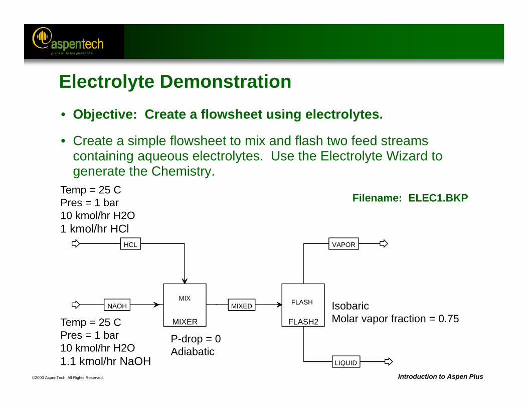
©2000 AspenTech. All Rights Reserved. Introduction to Aspen Plus
FLASH2
FLASHMIXED
VAPOR
LIQUID
MIXER
MIXNAOH
HCL
Temp = 25 CPres = 1 bar10 kmol/hr H2O1 kmol/hr HCl
P-drop = 0Adiabatic
IsobaricMolar vapor fraction = 0.75
Filename: ELEC1.BKP
Temp = 25 CPres = 1 bar10 kmol/hr H2O1.1 kmol/hr NaOH
Electrolyte Demonstration• Objective: Create a flowsheet using electrolytes.
• Create a simple flowsheet to mix and flash two feed streams containing aqueous electrolytes. Use the Electrolyte Wizard to generate the Chemistry.
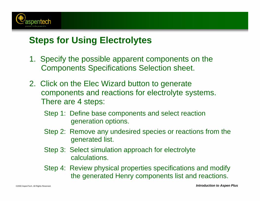
©2000 AspenTech. All Rights Reserved. Introduction to Aspen Plus
Steps for Using Electrolytes
1. Specify the possible apparent components on the Components Specifications Selection sheet.
2. Click on the Elec Wizard button to generate components and reactions for electrolyte systems. There are 4 steps:Step 1: Define base components and select reaction
generation options.Step 2: Remove any undesired species or reactions from the
generated list.Step 3: Select simulation approach for electrolyte
calculations.Step 4: Review physical properties specifications and modify
the generated Henry components list and reactions.
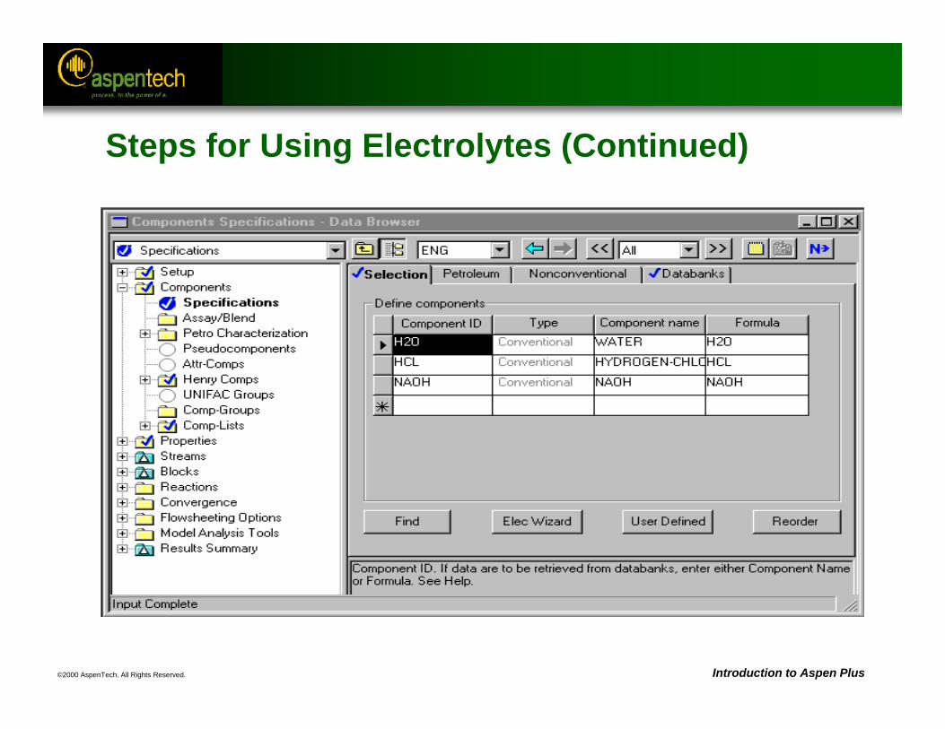
©2000 AspenTech. All Rights Reserved. Introduction to Aspen Plus
Steps for Using Electrolytes (Continued)
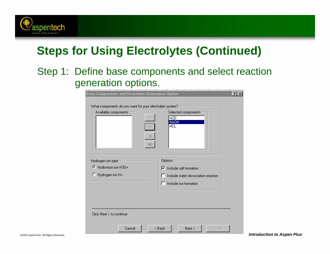
©2000 AspenTech. All Rights Reserved. Introduction to Aspen Plus
Steps for Using Electrolytes (Continued)Step 1: Define base components and select reaction
generation options.
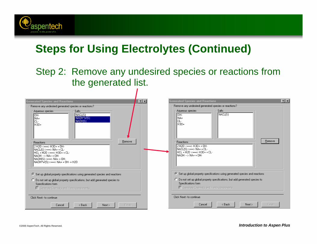
©2000 AspenTech. All Rights Reserved. Introduction to Aspen Plus
Steps for Using Electrolytes (Continued)
Step 2: Remove any undesired species or reactions from the generated list.
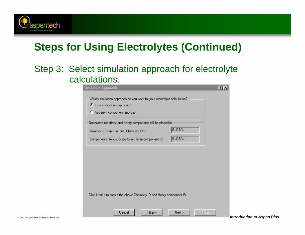
©2000 AspenTech. All Rights Reserved. Introduction to Aspen Plus
Steps for Using Electrolytes (Continued)
Step 3: Select simulation approach for electrolyte calculations.
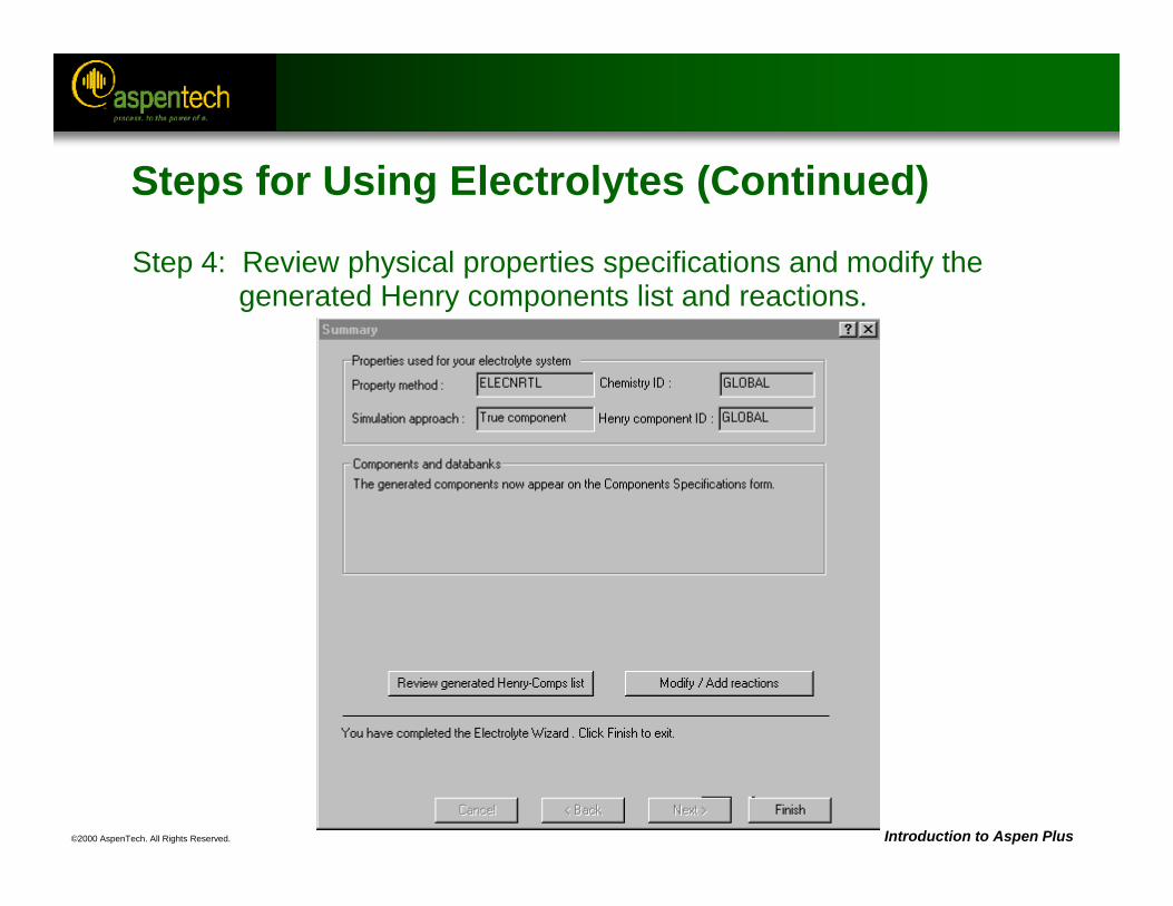
©2000 AspenTech. All Rights Reserved. Introduction to Aspen Plus
Steps for Using Electrolytes (Continued)
Step 4: Review physical properties specifications and modify the generated Henry components list and reactions.
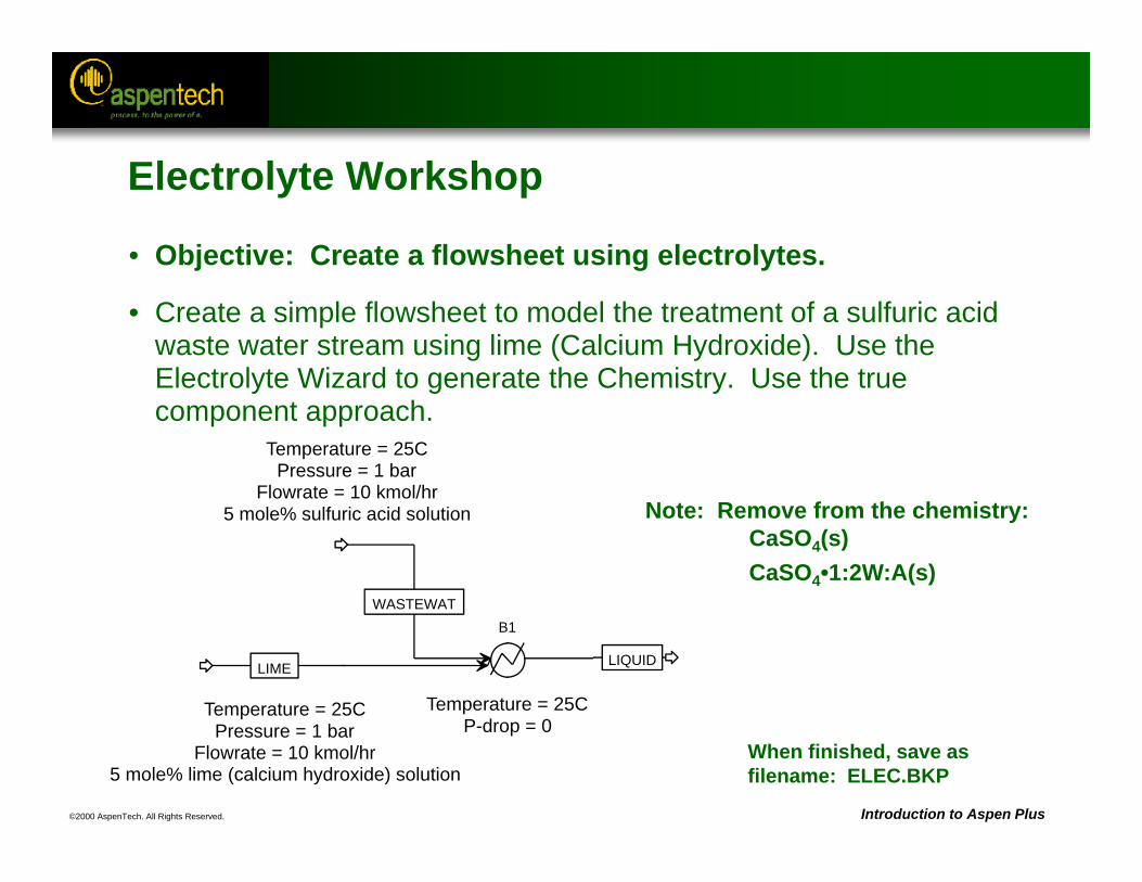
©2000 AspenTech. All Rights Reserved. Introduction to Aspen Plus
B1WASTEWAT
LIME LIQUID
Temperature = 25CPressure = 1 bar
Flowrate = 10 kmol/hr5 mole% lime (calcium hydroxide) solution
Temperature = 25CPressure = 1 bar
Flowrate = 10 kmol/hr5 mole% sulfuric acid solution
Temperature = 25CP-drop = 0
Note: Remove from the chemistry:CaSO4(s)CaSO4•1:2W:A(s)
When finished, save asfilename: ELEC.BKP
Electrolyte Workshop
• Objective: Create a flowsheet using electrolytes.
• Create a simple flowsheet to model the treatment of a sulfuric acid waste water stream using lime (Calcium Hydroxide). Use the Electrolyte Wizard to generate the Chemistry. Use the true component approach.
©2000 AspenTech. All Rights Reserved. Introduction to Aspen Plus
Electrolyte Workshop (Continued)
1. Open a new Electrolytes with Metric units flowsheet.
2. Draw the flowsheet.
3. Enter the necessary components and generate the electrolytes using the Electrolytes Wizard. Select the true approach and remove the solid salts not needed from the generated reactions.
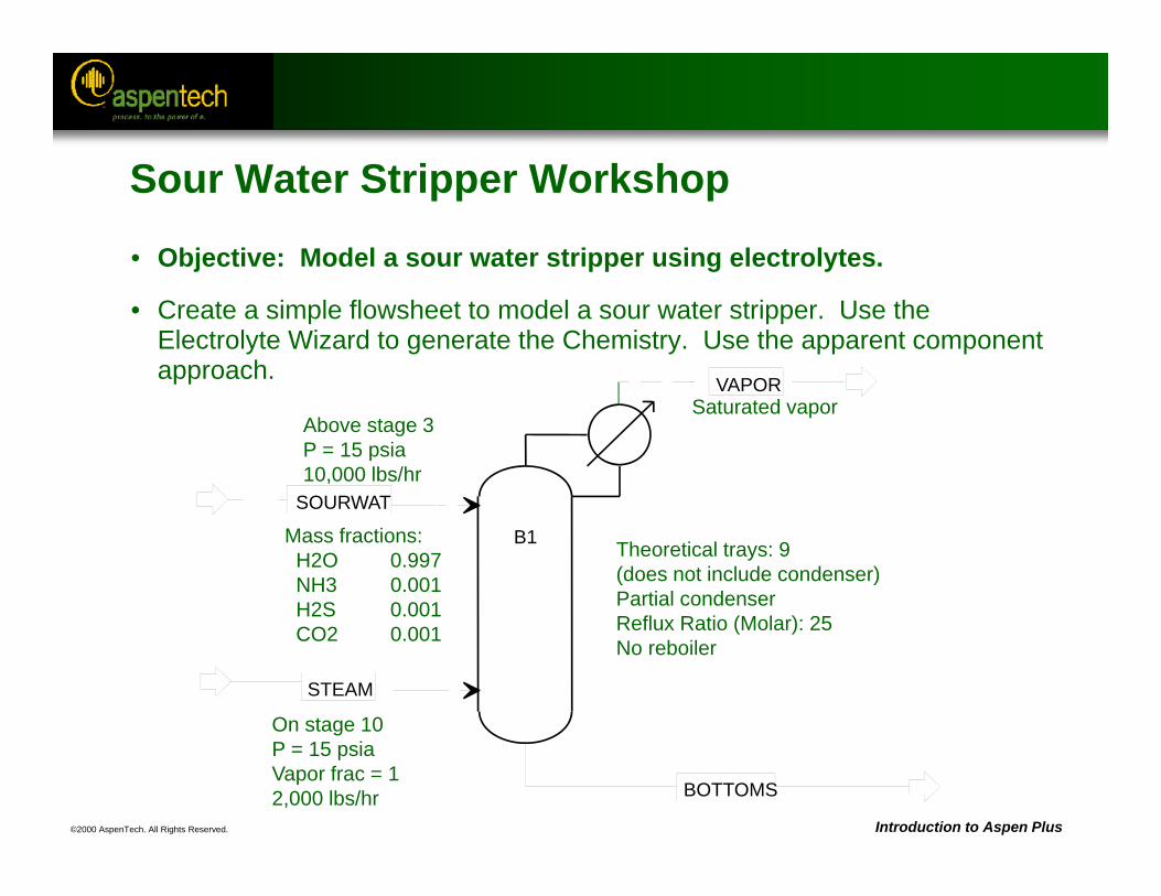
©2000 AspenTech. All Rights Reserved. Introduction to Aspen Plus
On stage 10P = 15 psiaVapor frac = 12,000 lbs/hr
Above stage 3P = 15 psia10,000 lbs/hr
Mass fractions:H2O 0.997NH3 0.001H2S 0.001CO2 0.001
Saturated vapor
Theoretical trays: 9 (does not include condenser)Partial condenserReflux Ratio (Molar): 25No reboiler
B1
SOURWAT
STEAM
BOTTOMS
VAPOR
Sour Water Stripper Workshop
• Objective: Model a sour water stripper using electrolytes.
• Create a simple flowsheet to model a sour water stripper. Use the Electrolyte Wizard to generate the Chemistry. Use the apparent component approach.
©2000 AspenTech. All Rights Reserved. Introduction to Aspen Plus
Sour Water Stripper Workshop (Continued)
1. Open a new Electrolytes with English units flowsheet.
2. Draw the flowsheet.
3. Enter the necessary components and generate the electrolytes using the Electrolytes Wizard. Select the apparent approach and remove all solid salts used in the generated reactions.
Questions: Why aren’t the ionic species’ compositions displayed on the results forms? How can they be added?
©2000 AspenTech. All Rights Reserved. Introduction to Aspen Plus
Save as: SOURWAT.BKP
Sour Water Stripper Workshop (Continued)
3. Add a sensitivity analysisa) Vary the steam flow rate from 1000-3000 lb/hr and tabulate
the ammonia concentration in the bottoms stream. The target is 50 ppm.
b) Vary the column reflux ratio from 10-50 and observe the condenser temperature. The target is 190 F.
4. Create design specificationsa) After hiding the sensitivity blocks, solve the column with two
design specifications. Use the targets and variables from part 3.
©2000 AspenTech. All Rights Reserved.
Solids Handling
Objective:
Provide an overview of the solid handling capabilities
Aspen Plus References: User Guide, Chapter 6, Specifying ComponentsPhysical Property Methods and Models Reference Manual, Chapter 3, Property Model Descriptions
©2000 AspenTech. All Rights Reserved. Introduction to Aspen Plus
Classes of Components
• Conventional Components– Vapor and liquid components– Solid salts in solution chemistry
• Conventional Inert Solids (CI Solids)– Solids that are inert to phase equilibrium and salt
precipitation/solubility
• Nonconventional Solids (NC Solids)– Heterogeneous substances inert to phase, salt, and chemical
equilibrium that cannot be represented with a molecular structure
©2000 AspenTech. All Rights Reserved. Introduction to Aspen Plus
Specifying Component Type
• When specifying components on the Components Specifications Selection sheet, choose the appropriate component type in the Type column.– Conventional - Conventional Components– Solid - Conventional Inert Solids– Nonconventional - Nonconventional Solids
©2000 AspenTech. All Rights Reserved. Introduction to Aspen Plus
Conventional Components
• Components participate in vapor and liquid equilibrium along with salt and chemical equilibrium.
• Components have a molecular weight.– e.g. water, nitrogen, oxygen, sodium chloride, sodium ions,
chloride ions– Located in the MIXED substream
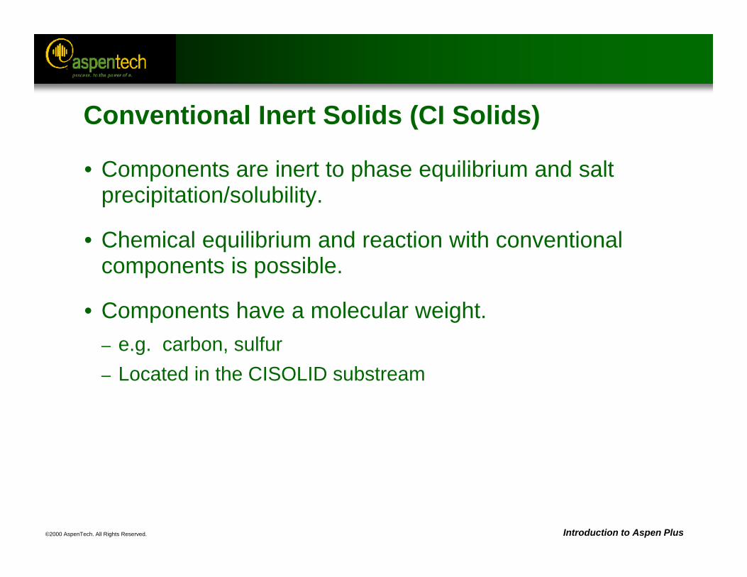
©2000 AspenTech. All Rights Reserved. Introduction to Aspen Plus
Conventional Inert Solids (CI Solids)
• Components are inert to phase equilibrium and salt precipitation/solubility.
• Chemical equilibrium and reaction with conventional components is possible.
• Components have a molecular weight. – e.g. carbon, sulfur– Located in the CISOLID substream

©2000 AspenTech. All Rights Reserved. Introduction to Aspen Plus
Nonconventional Solids (NC Solids)
• Components are inert to phase, salt or chemical equilibrium.
• Chemical reaction with conventional and CI Solid components is possible.
• Components are heterogeneous substances and do not have a molecular weight.– e.g. coal, char, ash, wood pulp– Located in the NC Solid substream
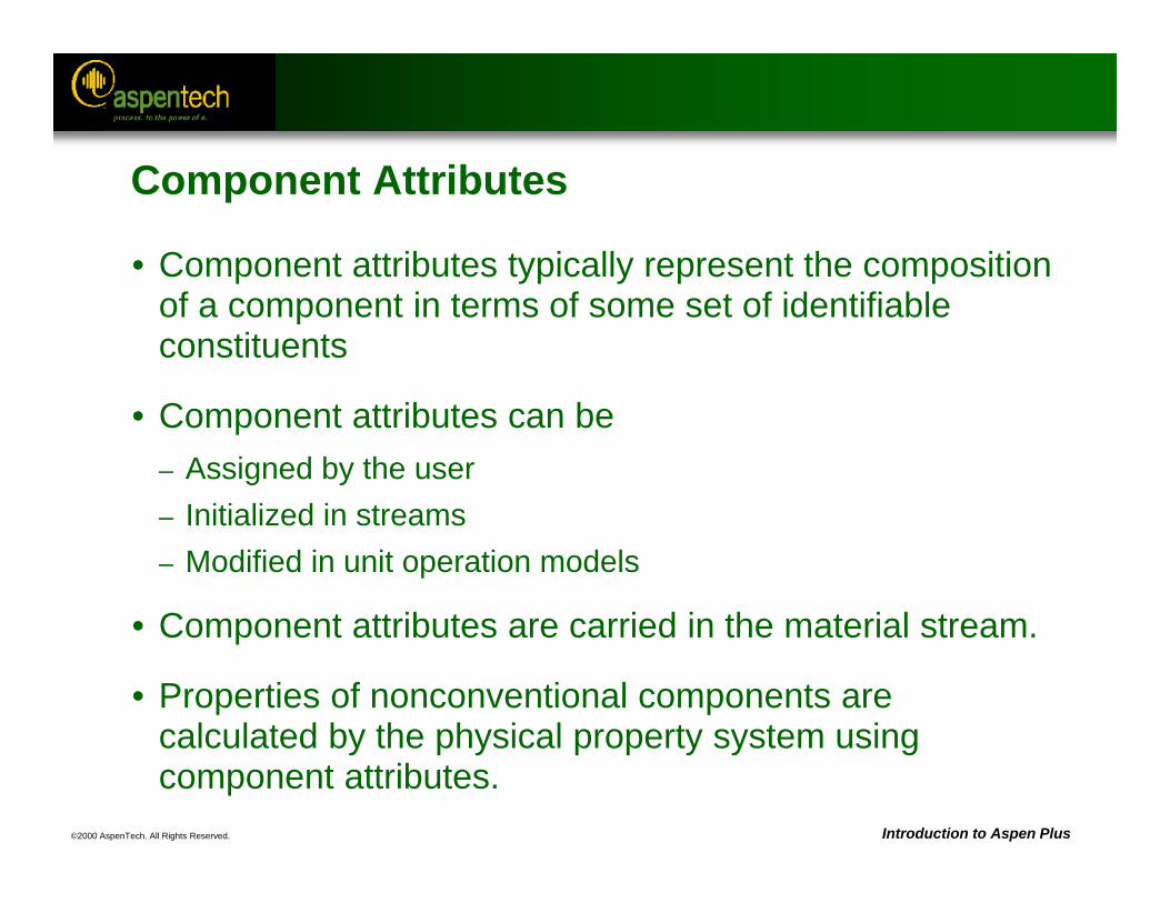
©2000 AspenTech. All Rights Reserved. Introduction to Aspen Plus
Component Attributes
• Component attributes typically represent the composition of a component in terms of some set of identifiable constituents
• Component attributes can be – Assigned by the user– Initialized in streams– Modified in unit operation models
• Component attributes are carried in the material stream.
• Properties of nonconventional components are calculated by the physical property system using component attributes.
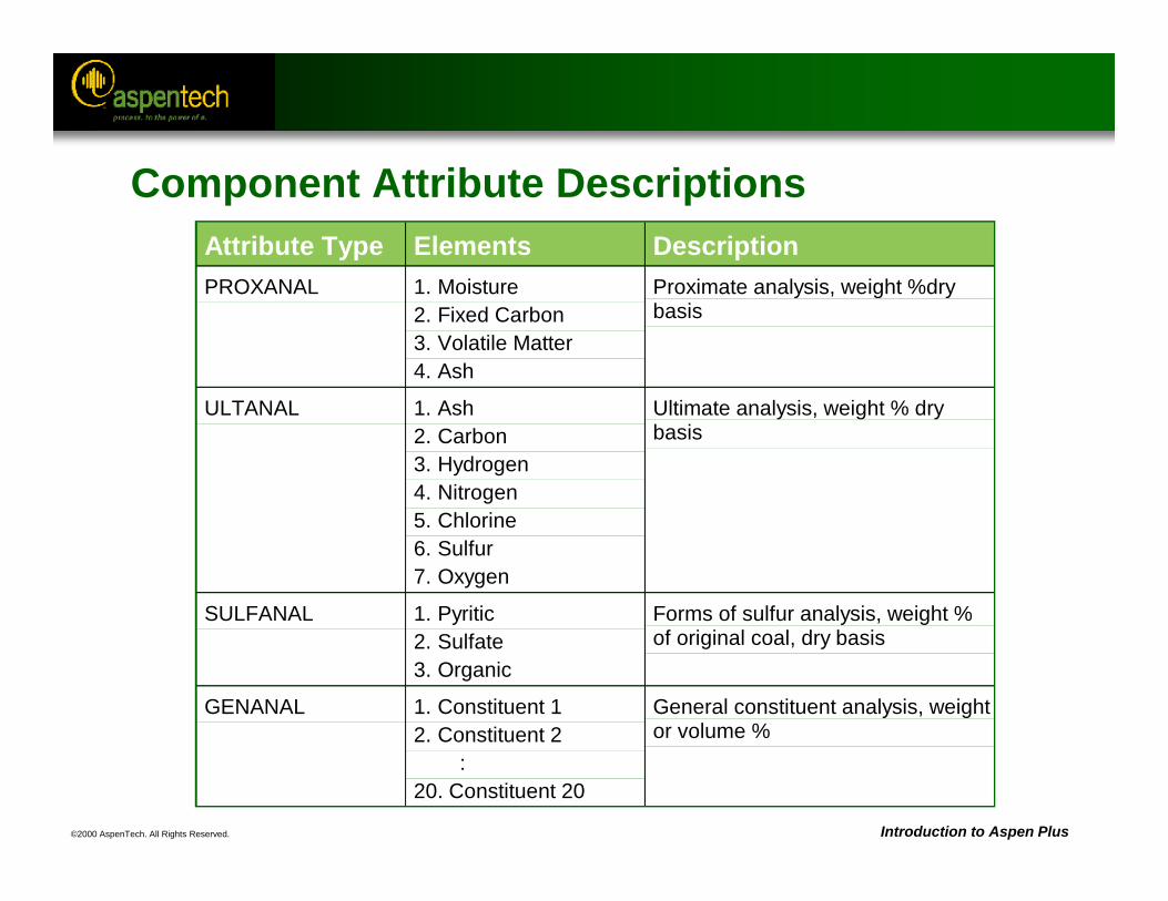
©2000 AspenTech. All Rights Reserved. Introduction to Aspen Plus
Component Attribute DescriptionsAttribute Type Elements DescriptionPROXANAL 1. Moisture
2. Fixed Carbon3. Volatile Matter4. Ash
Proximate analysis, weight %drybasis
ULTANAL 1. Ash2. Carbon3. Hydrogen4. Nitrogen5. Chlorine6. Sulfur7. Oxygen
Ultimate analysis, weight % drybasis
SULFANAL 1. Pyritic2. Sulfate3. Organic
Forms of sulfur analysis, weight %of original coal, dry basis
GENANAL 1. Constituent 12. Constituent 2 :20. Constituent 20
General constituent analysis, weightor volume %
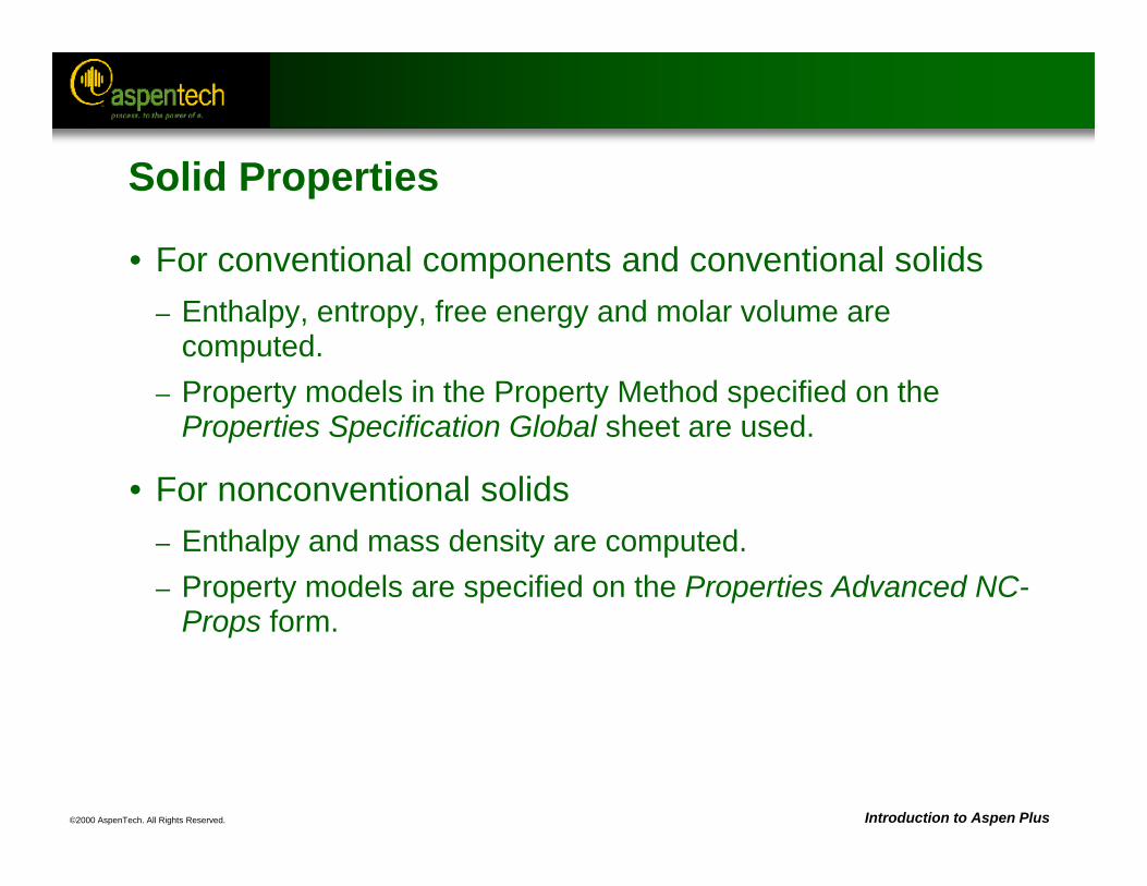
©2000 AspenTech. All Rights Reserved. Introduction to Aspen Plus
Solid Properties
• For conventional components and conventional solids– Enthalpy, entropy, free energy and molar volume are
computed. – Property models in the Property Method specified on the
Properties Specification Global sheet are used.
• For nonconventional solids– Enthalpy and mass density are computed.– Property models are specified on the Properties Advanced NC-
Props form.
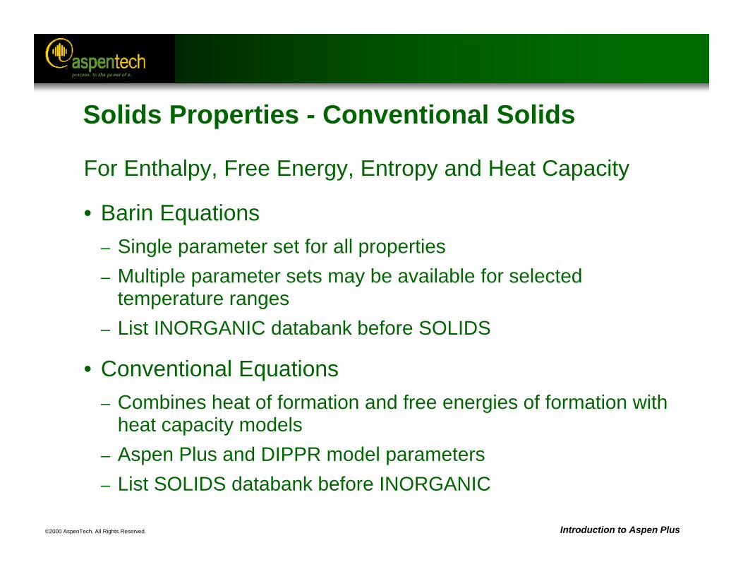
©2000 AspenTech. All Rights Reserved. Introduction to Aspen Plus
Solids Properties - Conventional Solids
For Enthalpy, Free Energy, Entropy and Heat Capacity
• Barin Equations– Single parameter set for all properties– Multiple parameter sets may be available for selected
temperature ranges– List INORGANIC databank before SOLIDS
• Conventional Equations– Combines heat of formation and free energies of formation with
heat capacity models– Aspen Plus and DIPPR model parameters– List SOLIDS databank before INORGANIC
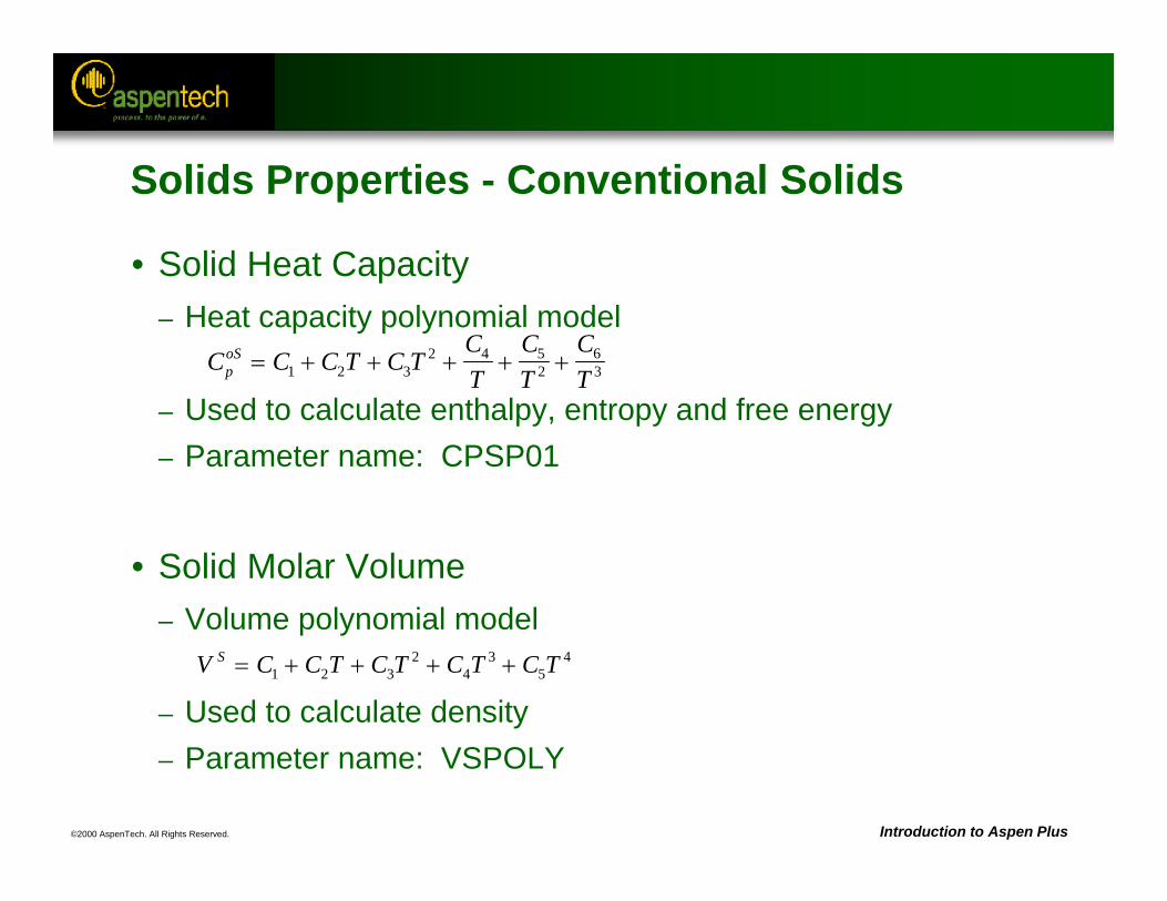
©2000 AspenTech. All Rights Reserved. Introduction to Aspen Plus
• Solid Heat Capacity– Heat capacity polynomial model
– Used to calculate enthalpy, entropy and free energy– Parameter name: CPSP01
• Solid Molar Volume– Volume polynomial model
– Used to calculate density– Parameter name: VSPOLY
C C C T C TCT
CT
CTp
oS 1 2 32 4 5
263
V C C T C T C T C TS 1 2 32
43
54
Solids Properties - Conventional Solids
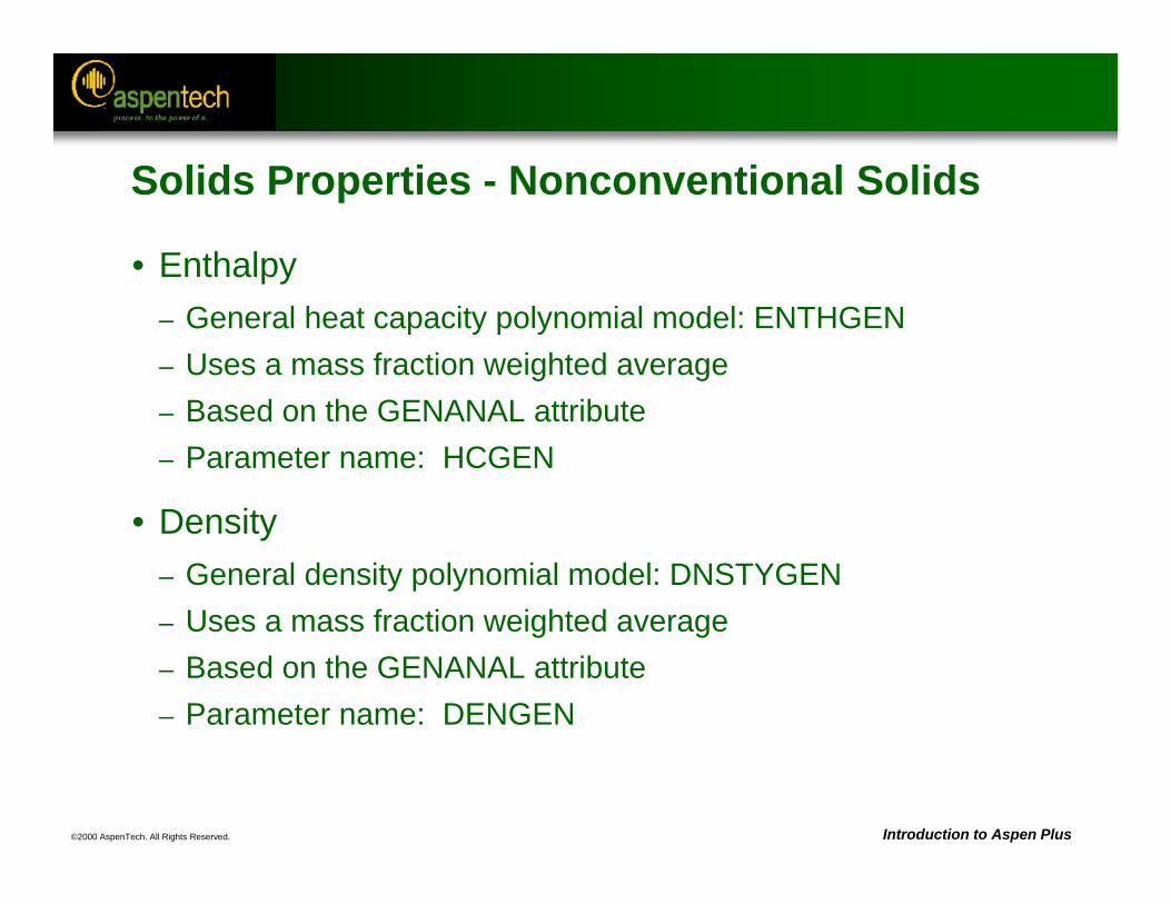
©2000 AspenTech. All Rights Reserved. Introduction to Aspen Plus
Solids Properties - Nonconventional Solids
• Enthalpy– General heat capacity polynomial model: ENTHGEN– Uses a mass fraction weighted average– Based on the GENANAL attribute– Parameter name: HCGEN
• Density– General density polynomial model: DNSTYGEN– Uses a mass fraction weighted average– Based on the GENANAL attribute– Parameter name: DENGEN
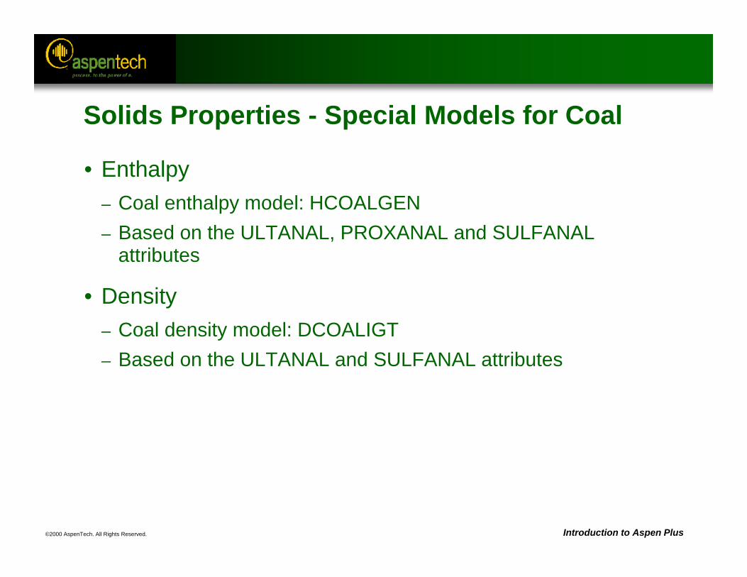
©2000 AspenTech. All Rights Reserved. Introduction to Aspen Plus
Solids Properties - Special Models for Coal
• Enthalpy– Coal enthalpy model: HCOALGEN– Based on the ULTANAL, PROXANAL and SULFANAL
attributes
• Density– Coal density model: DCOALIGT– Based on the ULTANAL and SULFANAL attributes

©2000 AspenTech. All Rights Reserved. Introduction to Aspen Plus
Built-in Material Stream Classes
Stream Class DescriptionCONVEN* Conventional components only
MIXNC Conventional and nonconventional solids
MIXCISLD Conventional components and inert solids
MIXNCPSD Conventional components and nonconventionalsolids with particle size distribution
MIXCIPSD Conventional components and inert solids withparticle size distribution
MIXCINC Conventional components and inert solids andnonconventional solids
MIXCINCPSD Conventional components and nonconventionalsolids with particle size distribution
* system default
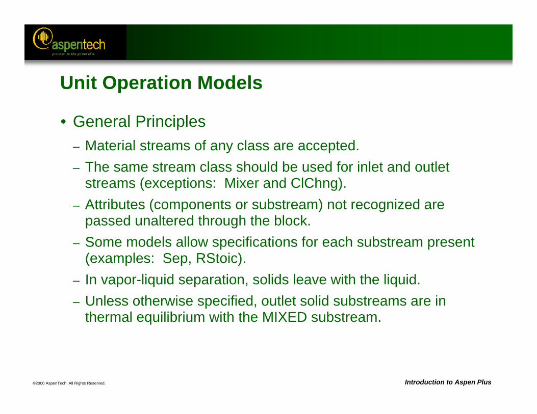
©2000 AspenTech. All Rights Reserved. Introduction to Aspen Plus
Unit Operation Models
• General Principles– Material streams of any class are accepted.– The same stream class should be used for inlet and outlet
streams (exceptions: Mixer and ClChng).– Attributes (components or substream) not recognized are
passed unaltered through the block.– Some models allow specifications for each substream present
(examples: Sep, RStoic).– In vapor-liquid separation, solids leave with the liquid.– Unless otherwise specified, outlet solid substreams are in
thermal equilibrium with the MIXED substream.
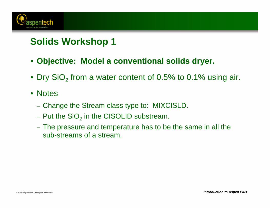
©2000 AspenTech. All Rights Reserved. Introduction to Aspen Plus
Solids Workshop 1
• Objective: Model a conventional solids dryer.
• Dry SiO2 from a water content of 0.5% to 0.1% using air.
• Notes– Change the Stream class type to: MIXCISLD.– Put the SiO2 in the CISOLID substream.– The pressure and temperature has to be the same in all the
sub-streams of a stream.
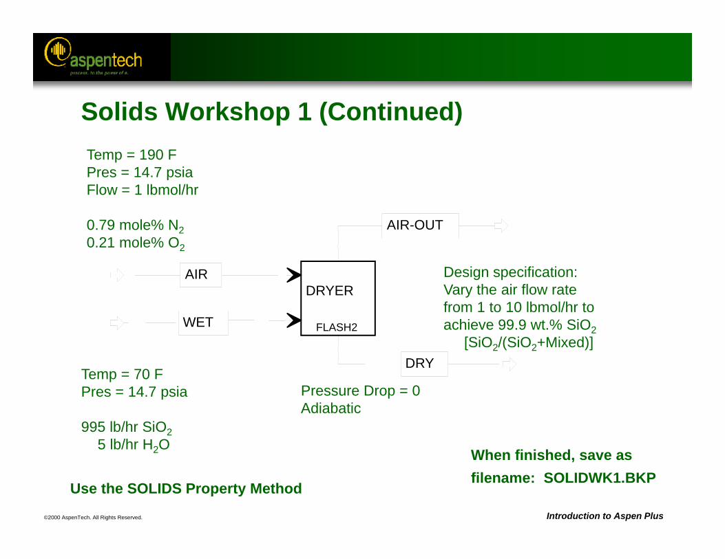
©2000 AspenTech. All Rights Reserved. Introduction to Aspen Plus
When finished, save asfilename: SOLIDWK1.BKP
Temp = 70 FPres = 14.7 psia
995 lb/hr SiO25 lb/hr H2O
FLASH2
DRYERAIR
WET
DRY
AIR-OUT
Pressure Drop = 0Adiabatic
Temp = 190 FPres = 14.7 psiaFlow = 1 lbmol/hr
0.79 mole% N20.21 mole% O2
Design specification:Vary the air flow ratefrom 1 to 10 lbmol/hr toachieve 99.9 wt.% SiO2
[SiO2/(SiO2+Mixed)]
Use the SOLIDS Property Method
Solids Workshop 1 (Continued)
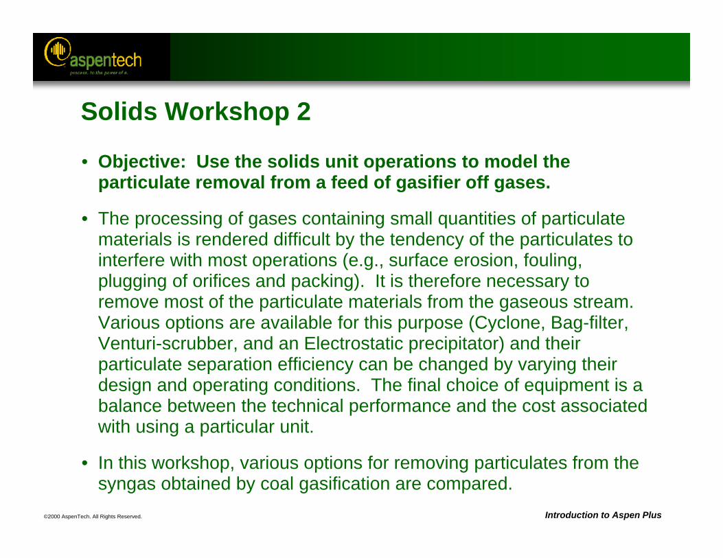
©2000 AspenTech. All Rights Reserved. Introduction to Aspen Plus
Solids Workshop 2
• Objective: Use the solids unit operations to model the particulate removal from a feed of gasifier off gases.
• The processing of gases containing small quantities of particulate materials is rendered difficult by the tendency of the particulates to interfere with most operations (e.g., surface erosion, fouling, plugging of orifices and packing). It is therefore necessary to remove most of the particulate materials from the gaseous stream. Various options are available for this purpose (Cyclone, Bag-filter, Venturi-scrubber, and an Electrostatic precipitator) and their particulate separation efficiency can be changed by varying their design and operating conditions. The final choice of equipment is a balance between the technical performance and the cost associated with using a particular unit.
• In this workshop, various options for removing particulates from the syngas obtained by coal gasification are compared.
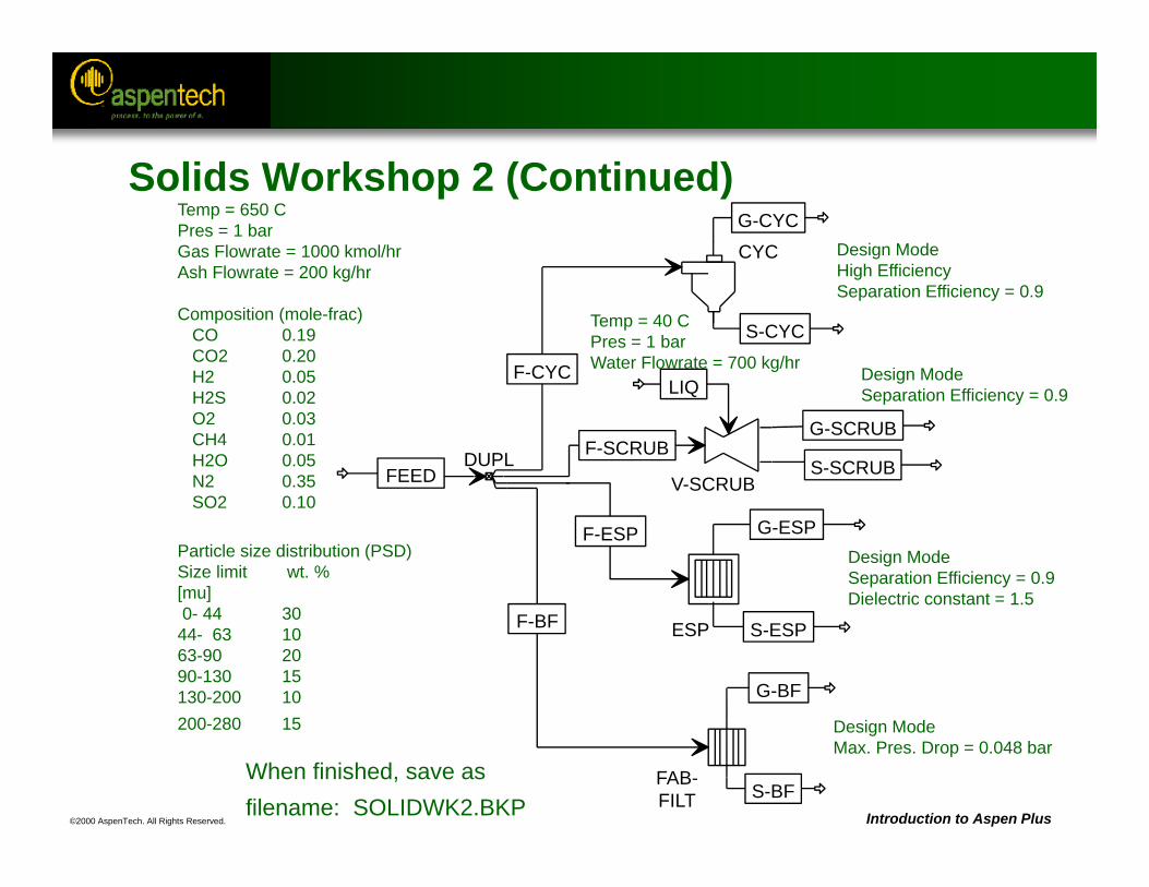
©2000 AspenTech. All Rights Reserved. Introduction to Aspen Plus
When finished, save asfilename: SOLIDWK2.BKP
Temp = 650 CPres = 1 barGas Flowrate = 1000 kmol/hr Ash Flowrate = 200 kg/hr
Composition (mole-frac)CO 0.19CO2 0.20H2 0.05H2S 0.02O2 0.03CH4 0.01H2O 0.05N2 0.35SO2 0.10
Particle size distribution (PSD)Size limit wt. %[mu]0- 44 30
44- 63 1063-90 2090-130 15130-200 10200-280 15
DUPL
CYC
FAB-FILT
ESP
V-SCRUBFEED
F-CYC
F-SCRUB
F-ESP
F-BF
S-BF
G-CYC
S-CYC
G-SCRUB
S-SCRUB
LIQ
G-ESP
S-ESP
G-BF
Temp = 40 CPres = 1 barWater Flowrate = 700 kg/hr
Design ModeMax. Pres. Drop = 0.048 bar
Design ModeHigh EfficiencySeparation Efficiency = 0.9
Design ModeSeparation Efficiency = 0.9Dielectric constant = 1.5
Design ModeSeparation Efficiency = 0.9
Solids Workshop 2 (Continued)
©2000 AspenTech. All Rights Reserved. Introduction to Aspen Plus
Solids Workshop 2 (Continued)
• Coal ash is mainly clay and heavy metal oxides and can be considered a non-conventional component.
• HCOALGEN and DCOALIGT can be used to calculate the enthalpy and material density of ash using the ultimate, proximate, and sulfur analyses (ULTANAL, PROXANAL, SULFANAL). These are specified on the Properties Advanced NC-Props form.
• Component attributes (ULTANAL, PROXANAL, SULFANAL) are specified on the Stream Input form. For ash, zero all non-ash attributes.
• The PSD limits can be changed on the Setup Substreams PSDform.
• Use the IDEAL Property Method.

©2000 AspenTech. All Rights Reserved.
Optimization
Objective:
Introduce the optimization capability in Aspen Plus
Aspen Plus References:User Guide, Chapter 22, Optimization
Related Topics:User Guide, Chapter 17, ConvergenceUser Guide, Chapter 18, Accessing Flowsheet Variables
©2000 AspenTech. All Rights Reserved. Introduction to Aspen Plus
Optimization
• Used to maximize/minimize an objective function
• Objective function is expressed in terms of flowsheet variables and In-Line Fortran.
• Optimization can have zero or more constraints.
• Constraints can be equalities or inequalities.
• Optimization is located under /Data/Model Analysis Tools/Optimization
• Constraint specification is under /Data/Model Analysis Tools/Constraint
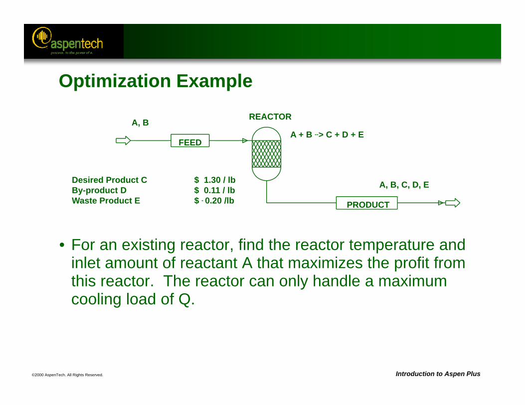
©2000 AspenTech. All Rights Reserved. Introduction to Aspen Plus
Desired Product C $ 1.30 / lbBy-product D $ 0.11 / lbWaste Product E $ - 0.20 /lb
FEED
PRODUCT
REACTORA, BA + B --> C + D + E
A, B, C, D, E
Optimization Example
• For an existing reactor, find the reactor temperature and inlet amount of reactant A that maximizes the profit from this reactor. The reactor can only handle a maximum cooling load of Q.
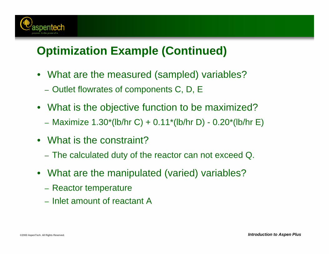
©2000 AspenTech. All Rights Reserved. Introduction to Aspen Plus
Optimization Example (Continued)
• What are the measured (sampled) variables? – Outlet flowrates of components C, D, E
• What is the objective function to be maximized?– Maximize 1.30*(lb/hr C) + 0.11*(lb/hr D) - 0.20*(lb/hr E)
• What is the constraint? – The calculated duty of the reactor can not exceed Q.
• What are the manipulated (varied) variables? – Reactor temperature– Inlet amount of reactant A
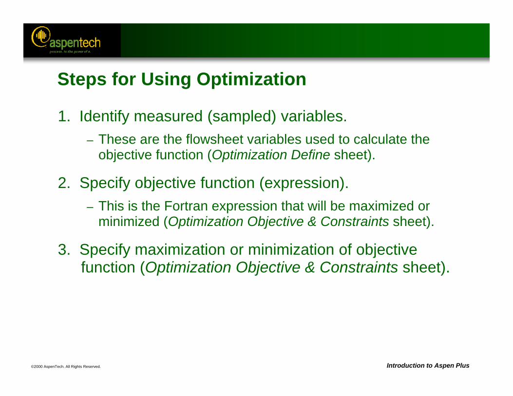
©2000 AspenTech. All Rights Reserved. Introduction to Aspen Plus
Steps for Using Optimization
1. Identify measured (sampled) variables.– These are the flowsheet variables used to calculate the
objective function (Optimization Define sheet).
2. Specify objective function (expression).– This is the Fortran expression that will be maximized or
minimized (Optimization Objective & Constraints sheet).
3. Specify maximization or minimization of objective function (Optimization Objective & Constraints sheet).
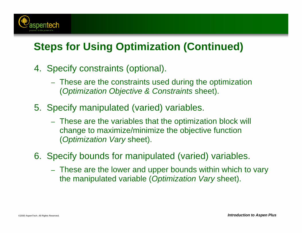
©2000 AspenTech. All Rights Reserved. Introduction to Aspen Plus
Steps for Using Optimization (Continued)
4. Specify constraints (optional).– These are the constraints used during the optimization
(Optimization Objective & Constraints sheet).
5. Specify manipulated (varied) variables.– These are the variables that the optimization block will
change to maximize/minimize the objective function (Optimization Vary sheet).
6. Specify bounds for manipulated (varied) variables.– These are the lower and upper bounds within which to vary
the manipulated variable (Optimization Vary sheet).
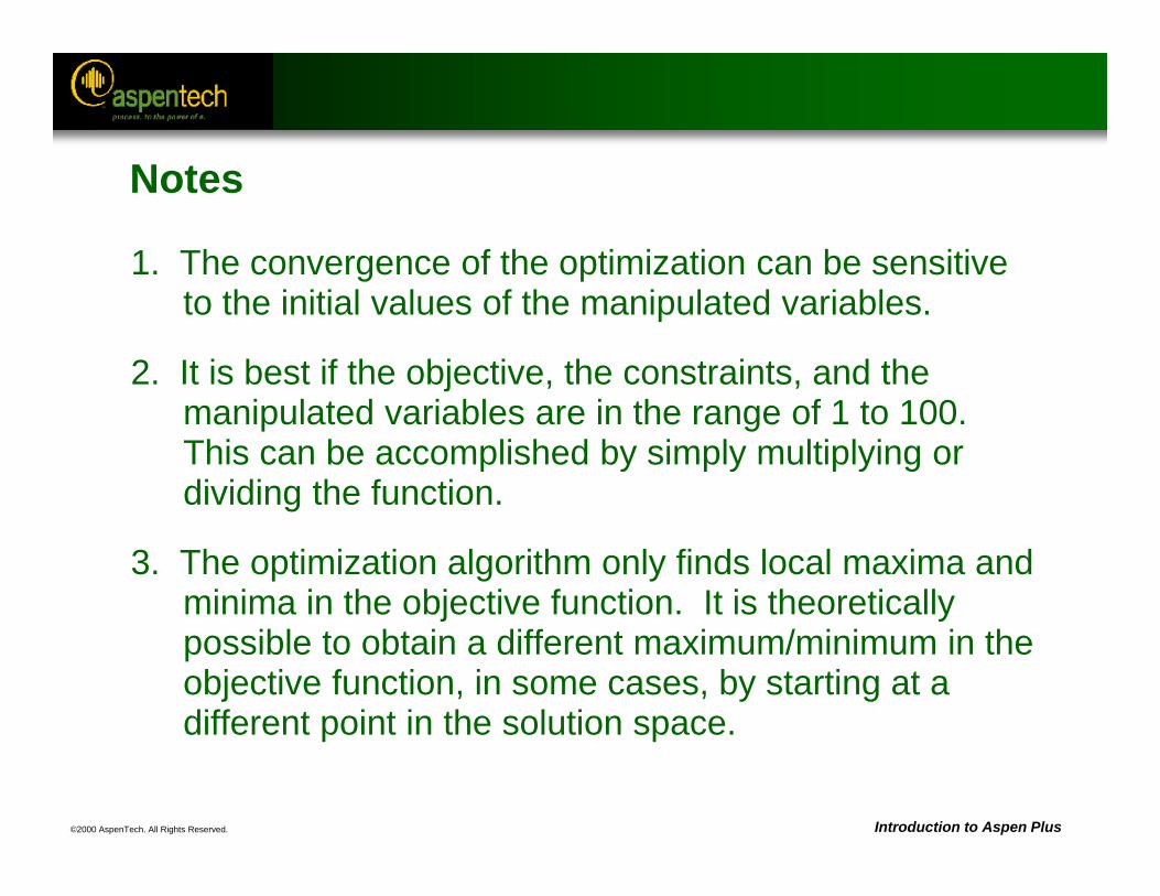
©2000 AspenTech. All Rights Reserved. Introduction to Aspen Plus
Notes
1. The convergence of the optimization can be sensitive to the initial values of the manipulated variables.
2. It is best if the objective, the constraints, and the manipulated variables are in the range of 1 to 100. This can be accomplished by simply multiplying or dividing the function.
3. The optimization algorithm only finds local maxima and minima in the objective function. It is theoretically possible to obtain a different maximum/minimum in the objective function, in some cases, by starting at a different point in the solution space.
©2000 AspenTech. All Rights Reserved. Introduction to Aspen Plus
Notes (Continued)
4. Equality constraints within an optimization are similar to design specifications.
5. If an optimization does not converge, run sensitivity studies with the same manipulated variables as the optimization, to ensure that the objective function is not discontinuous with respect to any of the manipulated variables.
6. Optimization blocks also have convergence blocks associated with them. Any general techniques used with convergence blocks can be used if the optimization does not converge.
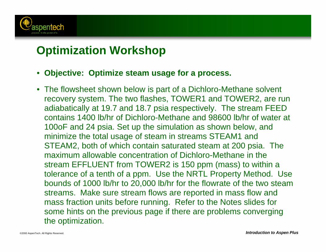
©2000 AspenTech. All Rights Reserved. Introduction to Aspen Plus
Optimization Workshop
• Objective: Optimize steam usage for a process.
• The flowsheet shown below is part of a Dichloro-Methane solvent recovery system. The two flashes, TOWER1 and TOWER2, are run adiabatically at 19.7 and 18.7 psia respectively. The stream FEED contains 1400 lb/hr of Dichloro-Methane and 98600 lb/hr of water at 100oF and 24 psia. Set up the simulation as shown below, and minimize the total usage of steam in streams STEAM1 and STEAM2, both of which contain saturated steam at 200 psia. The maximum allowable concentration of Dichloro-Methane in the stream EFFLUENT from TOWER2 is 150 ppm (mass) to within a tolerance of a tenth of a ppm. Use the NRTL Property Method. Use bounds of 1000 lb/hr to 20,000 lb/hr for the flowrate of the two steam streams. Make sure stream flows are reported in mass flow and mass fraction units before running. Refer to the Notes slides for some hints on the previous page if there are problems converging the optimization.
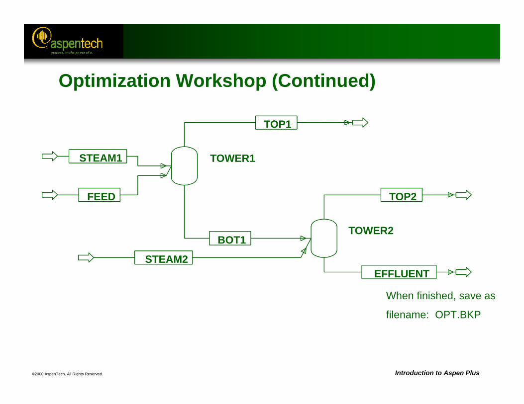
©2000 AspenTech. All Rights Reserved. Introduction to Aspen Plus
When finished, save as
filename: OPT.BKP
STEAM1
FEED
TOP1
BOT1
TOP2
EFFLUENTSTEAM2
TOWER1
TOWER2
Optimization Workshop (Continued)
©2000 AspenTech. All Rights Reserved.
RadFrac Convergence
Objective:
Introduce the convergence algorithms and initialization strategies available in RadFrac
Aspen Plus References:Unit Operation Models Reference Manual, Chapter 4, Columns
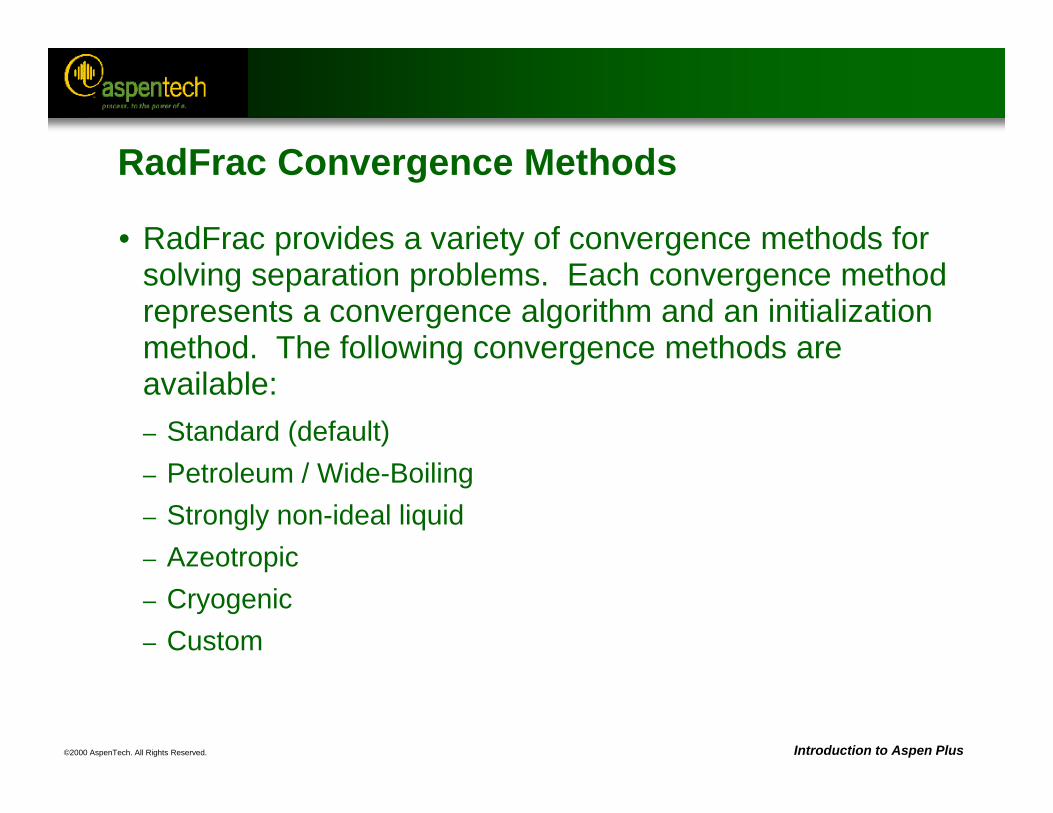
©2000 AspenTech. All Rights Reserved. Introduction to Aspen Plus
RadFrac Convergence Methods
• RadFrac provides a variety of convergence methods for solving separation problems. Each convergence method represents a convergence algorithm and an initialization method. The following convergence methods are available:– Standard (default)– Petroleum / Wide-Boiling– Strongly non-ideal liquid– Azeotropic– Cryogenic– Custom
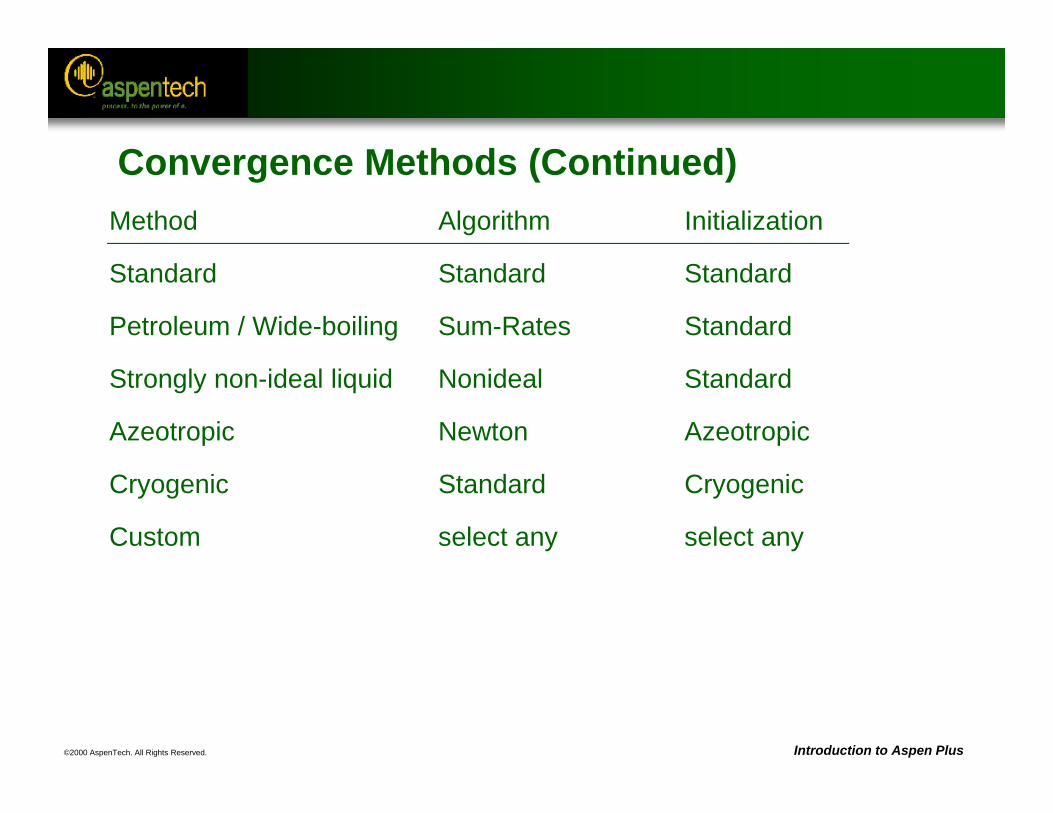
©2000 AspenTech. All Rights Reserved. Introduction to Aspen Plus
Method Algorithm Initialization
Standard Standard Standard
Petroleum / Wide-boiling Sum-Rates Standard
Strongly non-ideal liquid Nonideal Standard
Azeotropic Newton Azeotropic
Cryogenic Standard Cryogenic
Custom select any select any
Convergence Methods (Continued)
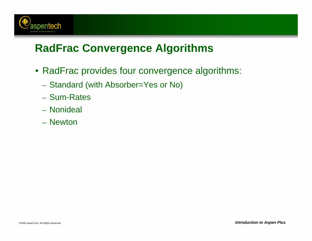
©2000 AspenTech. All Rights Reserved. Introduction to Aspen Plus
RadFrac Convergence Algorithms
• RadFrac provides four convergence algorithms:– Standard (with Absorber=Yes or No)– Sum-Rates– Nonideal– Newton
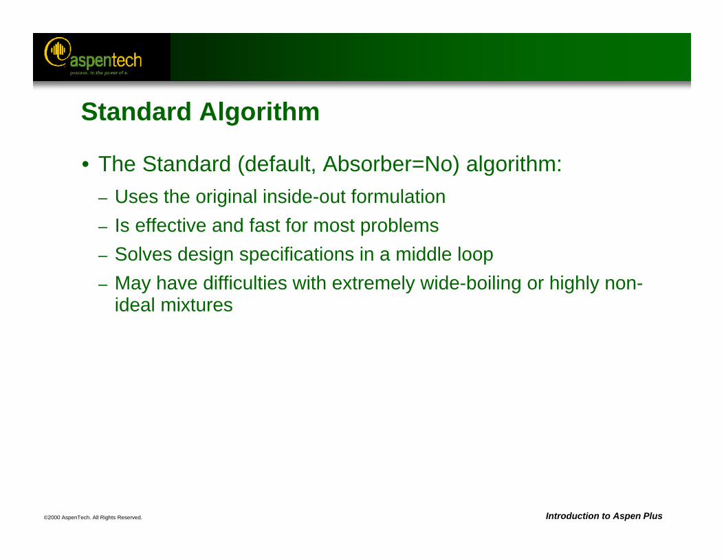
©2000 AspenTech. All Rights Reserved. Introduction to Aspen Plus
Standard Algorithm
• The Standard (default, Absorber=No) algorithm:– Uses the original inside-out formulation– Is effective and fast for most problems– Solves design specifications in a middle loop– May have difficulties with extremely wide-boiling or highly non-
ideal mixtures
©2000 AspenTech. All Rights Reserved. Introduction to Aspen Plus
Standard Algorithm (Continued)
• The Standard algorithm with Absorber=Yes:– Uses a modified formulation similar to the classical sum-rates
algorithm– Applies to absorbers and strippers only– Has fast convergence– Solves design specifications in a middle loop– May have difficulties with highly non-ideal mixtures
©2000 AspenTech. All Rights Reserved. Introduction to Aspen Plus
Sum-Rates Algorithm
• The Sum-Rates algorithm:– Uses a modified formulation similar to the classical sum-rates
algorithm– Solves design specifications simultaneously with the column-
describing equations– Is effective and fast for wide boiling mixtures and problems with
many design specifications– May have difficulties with highly non-ideal mixtures
©2000 AspenTech. All Rights Reserved. Introduction to Aspen Plus
Nonideal Algorithm
• The Nonideal algorithm:– Includes a composition dependency in the local physical
property models– Uses the continuation convergence method– Solves design specifications in a middle loop– Is effective for non-ideal problems
©2000 AspenTech. All Rights Reserved. Introduction to Aspen Plus
Newton Algorithm
• The Newton algorithm:– Is a classic implementation of the Newton method– Solves all column-describing equations simultaneously– Uses the dogleg strategy of Powell to stabilize convergence– Can solve design specifications simultaneously or in an outer
loop– Handles non-ideality well, with excellent convergence in the
vicinity of the solution– Is recommended for azeotropic distillation columns
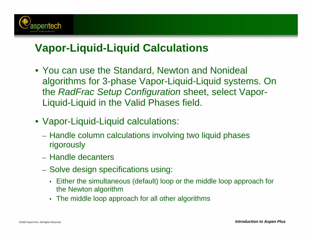
©2000 AspenTech. All Rights Reserved. Introduction to Aspen Plus
Vapor-Liquid-Liquid Calculations
• You can use the Standard, Newton and Nonideal algorithms for 3-phase Vapor-Liquid-Liquid systems. On the RadFrac Setup Configuration sheet, select Vapor-Liquid-Liquid in the Valid Phases field.
• Vapor-Liquid-Liquid calculations:– Handle column calculations involving two liquid phases
rigorously– Handle decanters– Solve design specifications using:
• Either the simultaneous (default) loop or the middle loop approach for the Newton algorithm
• The middle loop approach for all other algorithms
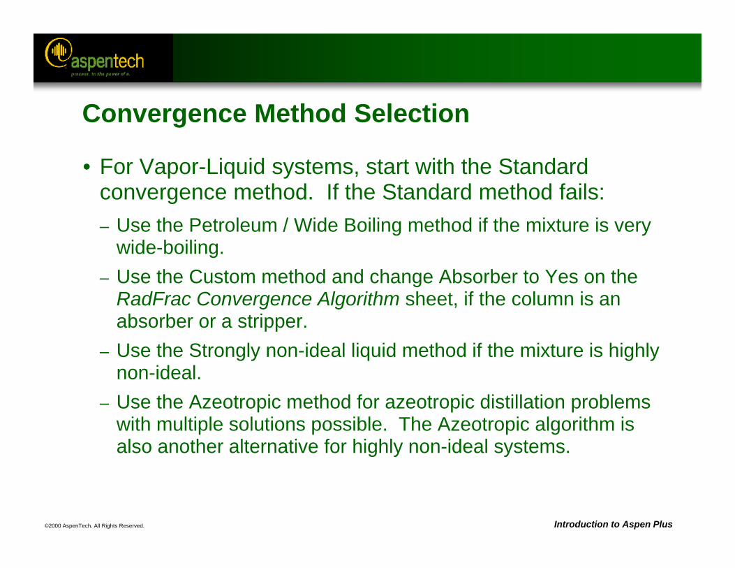
©2000 AspenTech. All Rights Reserved. Introduction to Aspen Plus
Convergence Method Selection
• For Vapor-Liquid systems, start with the Standard convergence method. If the Standard method fails:– Use the Petroleum / Wide Boiling method if the mixture is very
wide-boiling.– Use the Custom method and change Absorber to Yes on the
RadFrac Convergence Algorithm sheet, if the column is an absorber or a stripper.
– Use the Strongly non-ideal liquid method if the mixture is highly non-ideal.
– Use the Azeotropic method for azeotropic distillation problems with multiple solutions possible. The Azeotropic algorithm is also another alternative for highly non-ideal systems.
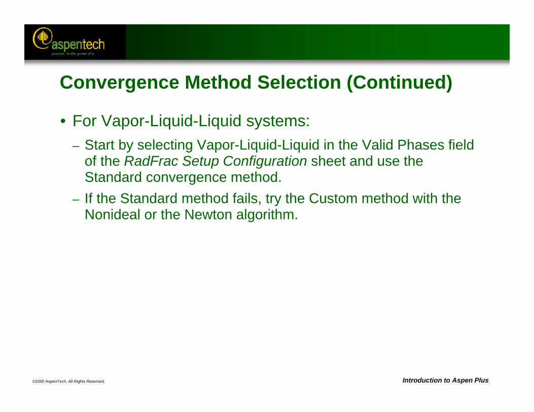
©2000 AspenTech. All Rights Reserved. Introduction to Aspen Plus
Convergence Method Selection (Continued)
• For Vapor-Liquid-Liquid systems:– Start by selecting Vapor-Liquid-Liquid in the Valid Phases field
of the RadFrac Setup Configuration sheet and use the Standard convergence method.
– If the Standard method fails, try the Custom method with the Nonideal or the Newton algorithm.
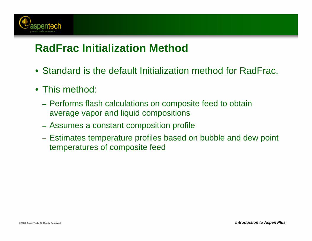
©2000 AspenTech. All Rights Reserved. Introduction to Aspen Plus
RadFrac Initialization Method
• Standard is the default Initialization method for RadFrac.
• This method: – Performs flash calculations on composite feed to obtain
average vapor and liquid compositions– Assumes a constant composition profile– Estimates temperature profiles based on bubble and dew point
temperatures of composite feed
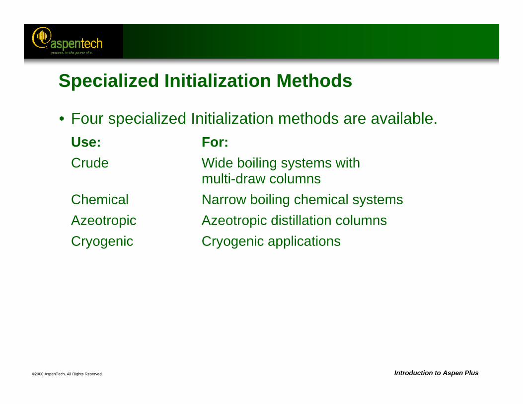
©2000 AspenTech. All Rights Reserved. Introduction to Aspen Plus
Specialized Initialization Methods
• Four specialized Initialization methods are available.Use: For:Crude Wide boiling systems with
multi-draw columnsChemical Narrow boiling chemical systemsAzeotropic Azeotropic distillation columnsCryogenic Cryogenic applications
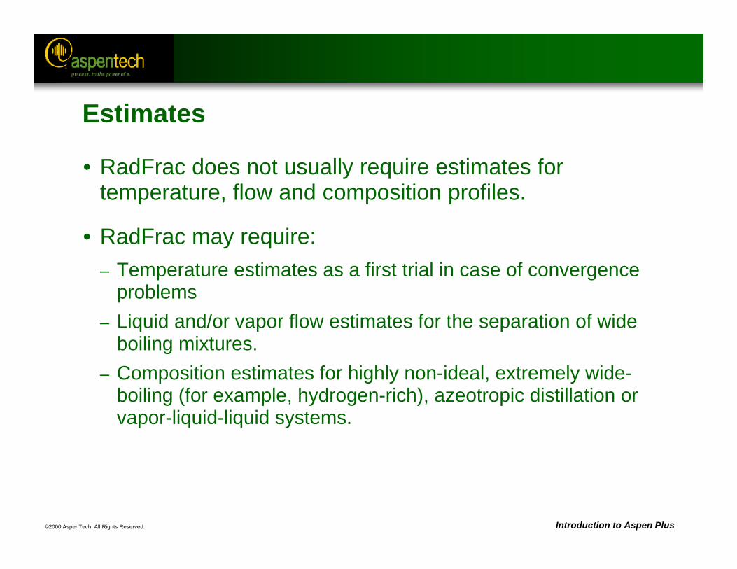
©2000 AspenTech. All Rights Reserved. Introduction to Aspen Plus
Estimates
• RadFrac does not usually require estimates for temperature, flow and composition profiles.
• RadFrac may require:– Temperature estimates as a first trial in case of convergence
problems– Liquid and/or vapor flow estimates for the separation of wide
boiling mixtures.– Composition estimates for highly non-ideal, extremely wide-
boiling (for example, hydrogen-rich), azeotropic distillation or vapor-liquid-liquid systems.
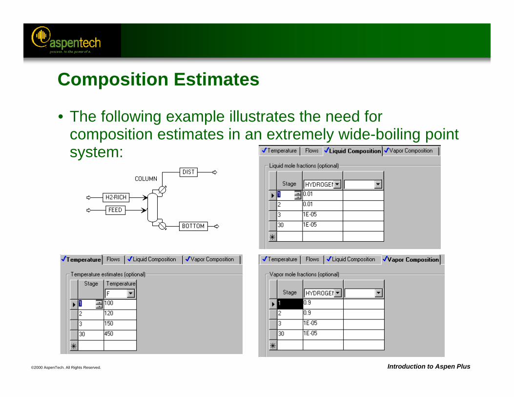
©2000 AspenTech. All Rights Reserved. Introduction to Aspen Plus
Composition Estimates
• The following example illustrates the need for composition estimates in an extremely wide-boiling point system:
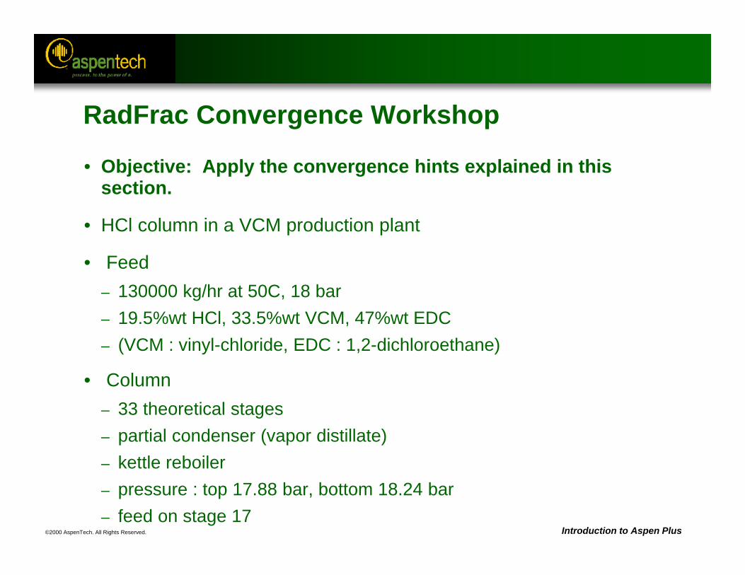
©2000 AspenTech. All Rights Reserved. Introduction to Aspen Plus
RadFrac Convergence Workshop
• Objective: Apply the convergence hints explained in this section.
• HCl column in a VCM production plant
• Feed– 130000 kg/hr at 50C, 18 bar– 19.5%wt HCl, 33.5%wt VCM, 47%wt EDC– (VCM : vinyl-chloride, EDC : 1,2-dichloroethane)
• Column– 33 theoretical stages– partial condenser (vapor distillate)– kettle reboiler– pressure : top 17.88 bar, bottom 18.24 bar– feed on stage 17
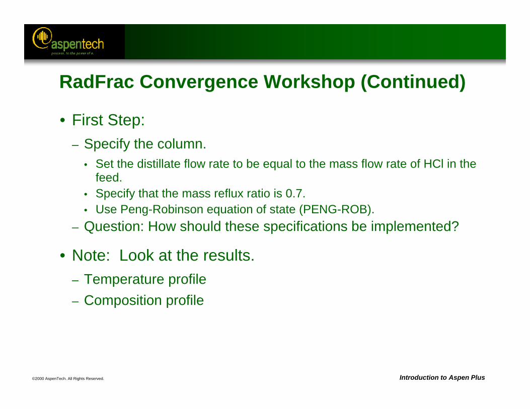
©2000 AspenTech. All Rights Reserved. Introduction to Aspen Plus
RadFrac Convergence Workshop (Continued)
• First Step: – Specify the column.
• Set the distillate flow rate to be equal to the mass flow rate of HCl in the feed.
• Specify that the mass reflux ratio is 0.7.• Use Peng-Robinson equation of state (PENG-ROB).
– Question: How should these specifications be implemented?
• Note: Look at the results.– Temperature profile– Composition profile
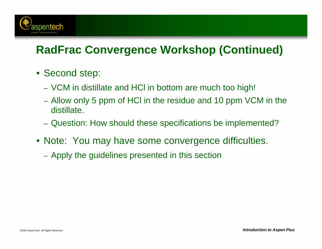
©2000 AspenTech. All Rights Reserved. Introduction to Aspen Plus
RadFrac Convergence Workshop (Continued)
• Second step: – VCM in distillate and HCl in bottom are much too high!– Allow only 5 ppm of HCl in the residue and 10 ppm VCM in the
distillate.– Question: How should these specifications be implemented?
• Note: You may have some convergence difficulties.– Apply the guidelines presented in this section
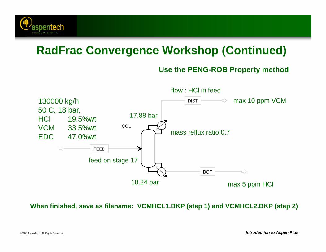
©2000 AspenTech. All Rights Reserved. Introduction to Aspen Plus
COL
FEED
DIST
BOT
feed on stage 17
130000 kg/h50 C, 18 bar,HCl 19.5%wtVCM 33.5%wtEDC 47.0%wt mass reflux ratio:0.7
flow : HCl in feedmax 10 ppm VCM
max 5 ppm HCl
17.88 bar
18.24 bar
When finished, save as filename: VCMHCL1.BKP (step 1) and VCMHCL2.BKP (step 2)
Use the PENG-ROB Property method
RadFrac Convergence Workshop (Continued)
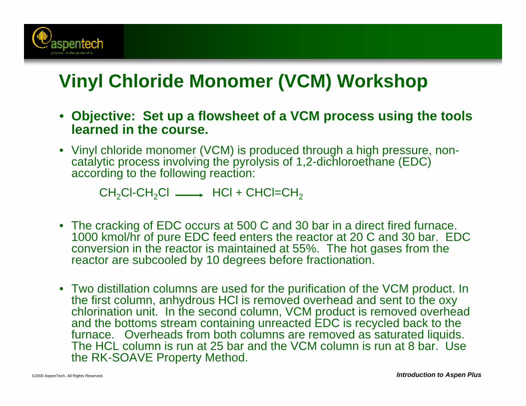
©2000 AspenTech. All Rights Reserved. Introduction to Aspen Plus
• Objective: Set up a flowsheet of a VCM process using the tools learned in the course.
• Vinyl chloride monomer (VCM) is produced through a high pressure, non-catalytic process involving the pyrolysis of 1,2-dichloroethane (EDC) according to the following reaction:
CH2Cl-CH2Cl HCl + CHCl=CH2
• The cracking of EDC occurs at 500 C and 30 bar in a direct fired furnace. 1000 kmol/hr of pure EDC feed enters the reactor at 20 C and 30 bar. EDC conversion in the reactor is maintained at 55%. The hot gases from the reactor are subcooled by 10 degrees before fractionation.
• Two distillation columns are used for the purification of the VCM product. In the first column, anhydrous HCl is removed overhead and sent to the oxy chlorination unit. In the second column, VCM product is removed overhead and the bottoms stream containing unreacted EDC is recycled back to the furnace. Overheads from both columns are removed as saturated liquids. The HCL column is run at 25 bar and the VCM column is run at 8 bar. Use the RK-SOAVE Property Method.
Vinyl Chloride Monomer (VCM) Workshop
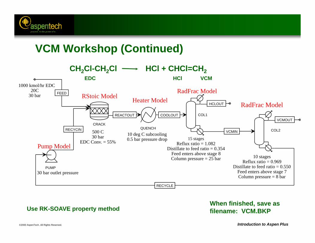
©2000 AspenTech. All Rights Reserved. Introduction to Aspen Plus
1000 kmol/hr EDC20C
30 bar
CRACK
FEED
RECYCIN
REACTOUT
PUMP
RECYCLE
QUENCH
COOLOUT COL1
HCLOUT
VCMIN COL2
VCMOUT
RStoic Model Heater Model
Pump Model
RadFrac Model
RadFrac Model
30 bar outlet pressure
500 C30 bar
EDC Conv. = 55%10 deg C subcooling0.5 bar pressure drop
10 stagesReflux ratio = 0.969
Distillate to feed ratio = 0.550Feed enters above stage 7Column pressure = 8 bar
15 stagesReflux ratio = 1.082
Distillate to feed ratio = 0.354Feed enters above stage 8Column pressure = 25 bar
When finished, save asfilename: VCM.BKPUse RK-SOAVE property method
CH2Cl-CH2Cl HCl + CHCl=CH2EDC HCl VCM
VCM Workshop (Continued)
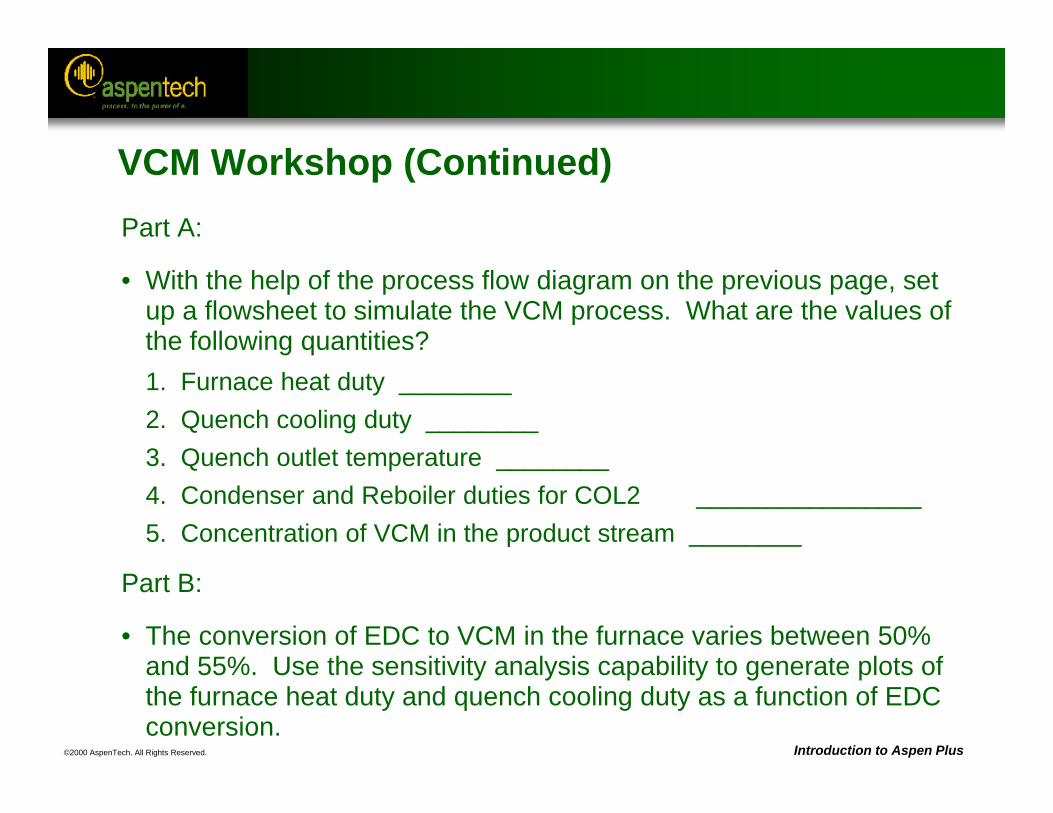
©2000 AspenTech. All Rights Reserved. Introduction to Aspen Plus
VCM Workshop (Continued)Part A:
• With the help of the process flow diagram on the previous page, set up a flowsheet to simulate the VCM process. What are the values of the following quantities? 1. Furnace heat duty ________2. Quench cooling duty ________3. Quench outlet temperature ________4. Condenser and Reboiler duties for COL2 ________________5. Concentration of VCM in the product stream ________
Part B:
• The conversion of EDC to VCM in the furnace varies between 50% and 55%. Use the sensitivity analysis capability to generate plots of the furnace heat duty and quench cooling duty as a function of EDC conversion.