cse 3442 windows ce embedded lab manual v1.3.1ranger.uta.edu/~walker/3442/web/labs/cse 3442 windows...
TRANSCRIPT
CSE 3442 Page 1 of 55
Windows CE Manual for embedded systems lab
CSE – 3442
Dr. Roger S. Walker
Computer Science Engineering The University of Texas at Arlington
Arlington, Texas

CSE 3442 Page 2 of 55
Contributions:
The following people have made contributions to this manual:
Rahul Rahul
Asbe Samar
Todor Boinovski
Tom Rethard
Jareer Abdel Qader

CSE 3442 Page 3 of 55
This manual describes the steps required to work on the embedded systems lab using
Windows CE. It covers
1. Building a Windows CE image
2. Downloading the image to the target platform.
3. Application development on Windows CE
4. Embedded labs using Windows CE
The version of Windows CE referred to is Windows CE .NET 4.1

CSE 3442 Page 4 of 55
Table of contents 1. Introduction................................................................................................................. 5 2. Application development using an embedded OS...................................................... 6 3. Labs based on Windows CE ....................................................................................... 7 4. Hardware support for Windows CE development ...................................................... 8 5. Customizing Windows CE platform for the target hardware: .................................... 9 6. Steps to create the Windows CE platform and download it to your target device ... 10
a. Platform development........................................................................................... 10 b. Application Development ..................................................................................... 26
i. Application Development using the SDK and Embedded VC++..................... 26 ii. Application development using Platform Builder ............................................ 37
c. Downloading the image ........................................................................................ 40 7. Lab reports ................................................................................................................ 44 8. Lab 1: Downloading the Windows CE image to the embedded PC. ........................ 46
a. Problem Statement:............................................................................................... 46 b. Expected time of completion: ............................................................................... 46 c. Problem Description: ............................................................................................ 46 d. Windows CE programming considerations for the lab......................................... 46
9. Lab 2: parallel I/O using 8255. ................................................................................. 47 a. Problem Statement:............................................................................................... 47 b. Expected time of completion: ............................................................................... 47 c. Problem Description: ............................................................................................ 47 d. Windows CE programming considerations for the lab......................................... 49
10. Lab 3: Analog to digital conversion...................................................................... 50 a. Problem Statement:............................................................................................... 50 b. Expected time of completion: ............................................................................... 50 c. Problem Description: ............................................................................................ 50 d. Windows CE programming considerations for the lab......................................... 50
11. Lab 4: Timers and Stepping motors...................................................................... 51 a. Problem Statement:............................................................................................... 51 b. Expected time of completion: ............................................................................... 51 c. Problem Description: ............................................................................................ 51 d. Windows CE programming considerations for the lab......................................... 52
12. Lab 5: Interrupts.................................................................................................... 53 a. Problem Statement:............................................................................................... 53 b. Expected time of completion: ............................................................................... 53 c. Problem Description: ............................................................................................ 53 d. Windows CE programming considerations for the lab......................................... 53
13. Lab 6: Serial I/O over COM port.......................................................................... 54 a. Problem Statement:............................................................................................... 54 b. Expected time of completion: ............................................................................... 54 c. Problem Description: ............................................................................................ 54 d. Windows CE programming considerations for the lab......................................... 54
14. Steps to Create CE Platform ................................................................................. 55

CSE 3442 Page 5 of 55
1. Introduction
Many consumer electronic devices now have embedded processors to control their
functions, making these devices embedded systems. Systems as complex as PDA's and
cell-phones, or even simpler systems such as a toaster oven can be an embedded system.
The demand for embedded systems grows even more as electronic devices become more
compact and more complex. As a result of this demand, the study of embedded operating
systems and development environments have become crucial. With every successive
generation of technology, everything from VCRs to industrial robots, have more and
more features added. The applications for these systems require development tools that
support embedded operating systems in order to keep the development time reasonable.
Among the more popular embedded operating systems are VxWorks, embedded Linux and
Windows CE.

CSE 3442 Page 6 of 55
2. Application development using an embedded OS
Developing applications for an embedded operating system has several differences from general
program development on a full computer system. Generally, a program is written on a computer
and then generated into an executable or library using a compiler. Then, the program can be
integrated with other programs and run on the main platform. Older embedded systems were
much the same way, using DOS, for example. The program would be written on a machine with a
compiler like Borland C, compiled, and then moved to an embedded system running the same
operating system.
Building applications on embedded systems has changed over time, especially with the growth of
smaller and more complex devices. In order to improve the speed of development time, tools and
environments have been created to assist in writing applications. These Integrated Development
Environments (IDE) differ from vendor to vendor, and consist of multiple tools to help the system
developer complete the project. An IDE, for example, allows a developer to add and remove the
conditions and components from an operating system in order to meet the memory requirements
of an embedded module. Also, the IDE can assist in the development of a program by generating
necessary files, or in some cases have programming ability as part of the IDE interface
An IDE interface creates an image. An image is the equivalent to an Operating System (OS) in
Desktop systems. The image is then transferred onto the target platform (embedded system) using
an Ethernet or other connection from the host machine. Once the transfer is complete, the
embedded system can then run independently of the host machine.
For the rest of this manual, the labs and discussions will be based on the Windows CE IDE.
Windows CE provides a Platform Builder, which allows a user to selectively add desired features
components to a Platform. For example, multimedia handlers can be easily excluded from the OS
to free up hardware resources. if a system is meant to be diskless, then the handling for disk
drives can be pulled from the OS in order to free up system resources.
Platform Builder supplies a compiler for developing applications as well as the tools for creating
an OS image, and is capable of transferring the application when the image is loaded onto the
embedded sys tem.

CSE 3442 Page 7 of 55
3. Labs based on Windows CE
There will be six labs based on Windows CE.
1. Lab 1 will involve creation of a Windows CE platform and downloading it into the target
(embedded PC) over an Ethernet connection.
2. Lab2 will involve Parallel I/O using the 8255 chip.
3. Lab 3 will involve analog to Digital conversion using ADC804
4. Lab 4 will involve interface and operation of stepper motor using the 8253-timer chip.
5. Lab 5 will involve understanding interrupts.
6. Lab 6 will involve serial communication over the COM port.

CSE 3442 Page 8 of 55
4. Hardware support for Windows CE development
For an embedded hardware (target) to run a Windows CE based embedded system, the hardware
should be able to support the Windows CE operating system. This support involves the Board
Support Package (BSP).
The BSP contains:
1. The OEM Adaptation Layer (OAL). The OEM Adaptation layer (also known as the
Hardware Abstraction Layer) is supplied by the OEM (Original Equipment
Manufacturer) to run the operating system on the specific hardware platform, which the
OEM provides. In the absence of an OAL, the operating system would need to be
different for each underlying architecture depending on such factors such as instruction
set etc.
2. The Device Drivers: The device drivers provide the necessary support to the operating
system by the device manufacturers for the device to interact with the existing system

CSE 3442 Page 9 of 55
5. Customizing Windows CE platform for the target hardware:
The entire software (binary file), which runs on the target hardware, is known as the image. The
integration of the image with the device drivers and OAL is known as platform. This image
contains the operating system executable, and can also contain the executables of a developer's
applications.
Microsoft provides an Integrate Development Environment (IDE), which helps the developer in
building, customizing and configuring the platform depending on the unique needs of the
developer. For example, a developer might decide to have the target platform, which has x86
architecture but does not need network support. The platform builder contains modules of binary
code, which support various hardware platforms and their various configurations. Depending on
the options selected by the user, the relevant modules are selected and linked together to form the
platform.
CSE 3442 Page 10 of 55
6. Steps to create the Windows CE platform and download it to your target device
Creation of the Windows CE platform is divided into:
i. Platform development
ii. Application development
iii. Image download
Start the Platform Builder application and follow the steps given below.
a. Platform development
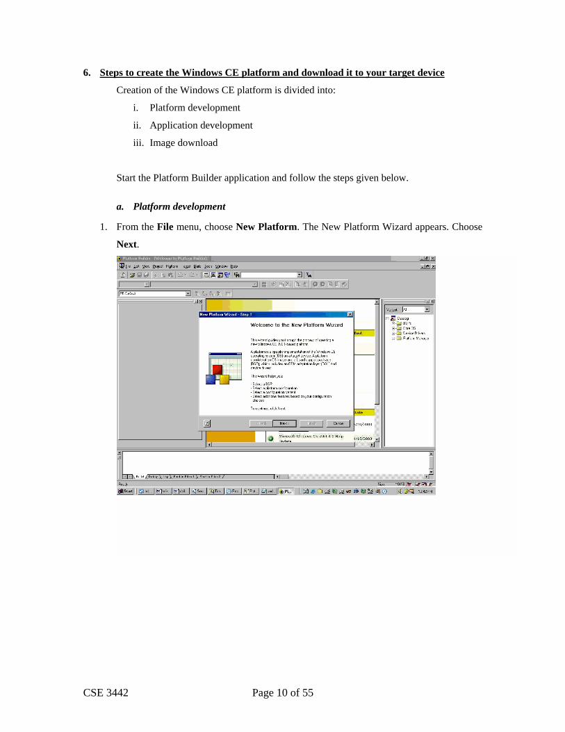
1. From the File menu, choose New Platform. The New Platform Wizard appears. Choose
Next.

CSE 3442 Page 11 of 55
2. New Platform Wizard – Step 2, Board Support Packages (BSPs) appears. Select the
CEPC X86 BSP. A CEPC is an x86-based desktop computer that runs Windows CE-
based applications and drivers. Choose Next.

CSE 3442 Page 12 of 55
3. New Platform Wizard – Step 3, Platform Configuration appears. Enter a name for your
platform in the Platform Name box. You can type a new path for the platform in the
Location box or use the Browse button to select a platform directory. The path cannot be
longer than 32 characters and cannot contain spaces. Select ‘Custom configuration’.
CSE 3442 Page 13 of 55
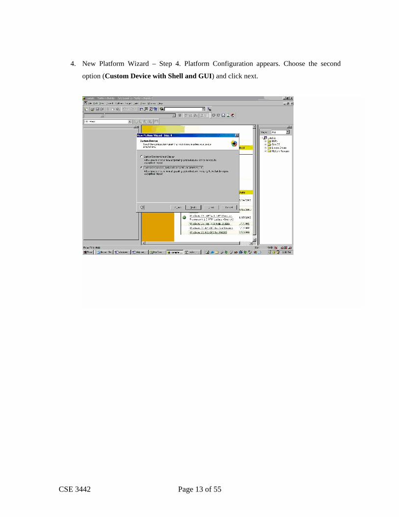
4. New Platform Wizard – Step 4. Platform Configuration appears. Choose the second
option (Custom Device with Shell and GUI) and click next.

CSE 3442 Page 14 of 55
5. New Platform Wizard – Step 5, Platform Configuration appears. Select ‘C Libraries &
Runtimes’ and click Next. If you observe this window carefully, you will notice the
change in the memory size of the platform as the features are added or dropped.

CSE 3442 Page 15 of 55
6. New Platform Wizard – Step 6, Platform Configuration appears. Click Next without
selecting anything.

CSE 3442 Page 16 of 55
7. New Platform Wizard – Step 7, Platform Configuration appears. Select Serial Port,
Parallel Port and Debugging Tools. Click Next.

CSE 3442 Page 17 of 55
8. New Platform Wizard – Step 8, Platform Configuration appears. Click Next without
selecting anything.

CSE 3442 Page 18 of 55
9. New Platform Wizard – Step 9, Platform Configuration appears. Click Next without
selecting anything.

CSE 3442 Page 19 of 55
10. New Platform Wizard – Step 10, Platform Configuration appears. Click Next without
selecting anything.

CSE 3442 Page 20 of 55
11. New Platform Wizard – Step 11, Platform Configuration appears. Click Next without
selecting anything.

CSE 3442 Page 21 of 55
12. New Platform Wizard – Step 12, Platform Configuration appears. Click Next without
selecting anything.
CSE 3442 Page 22 of 55
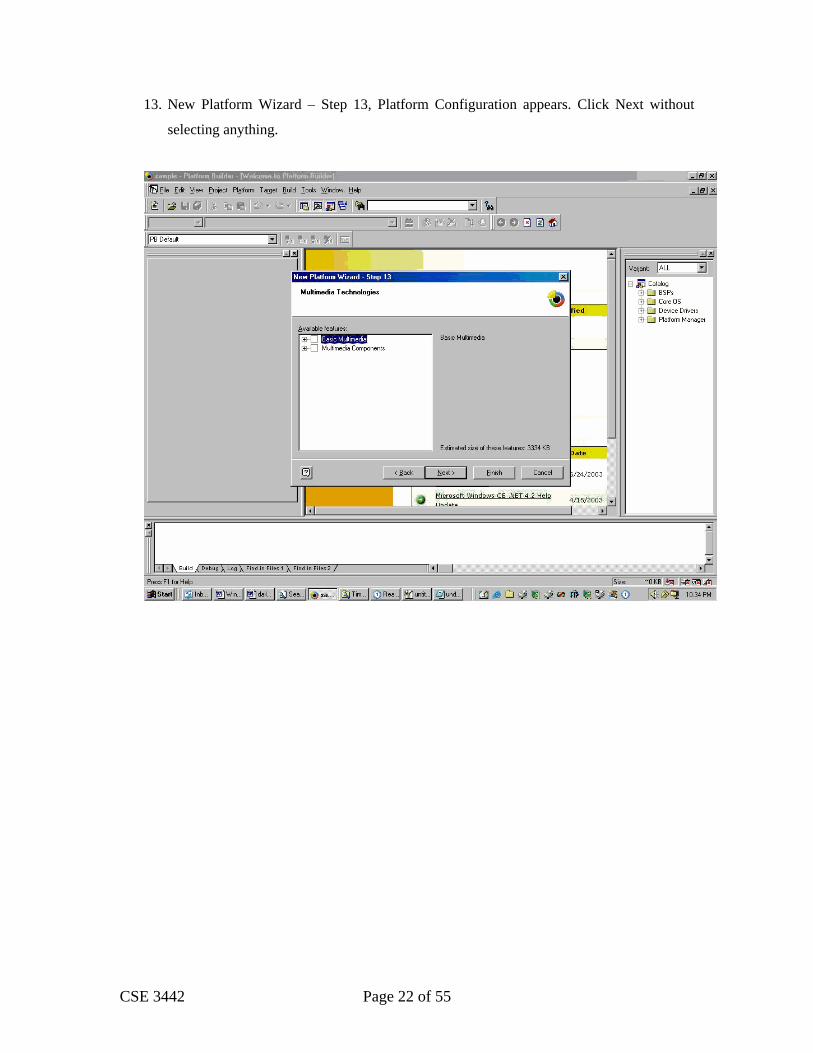
13. New Platform Wizard – Step 13, Platform Configuration appears. Click Next without
selecting anything.

CSE 3442 Page 23 of 55
14. New Platform Wizard – Step 14, Platform Configuration appears. Click Next without
selecting anything.

CSE 3442 Page 24 of 55
15. New Platform Wizard – Step 15, Platform Configuration appears. Select ‘Shell and User
Interface’ and Click Next.

CSE 3442 Page 25 of 55
16. The Special Feature Notifications page appears, listing the special notifications
associated with the features in your platform. A congratulations page appears, with
options for ending the wizard. Choose Finish to create the new platform, or select one of
the options to proceed.

CSE 3442 Page 26 of 55
b. Application Development
Now that the platform is prepared, we can begin to create a sample application. The application development on the Platform Builder IDE or Embedded VC++ closely follows the Visual Studio model. You can either develop your application in the Platform Builder or you can use the SDK and Embedded Visual C++. Note: If you use Platform Builder and compile your application in your platform you will have to recompile your project and then the platform every time you change your code in order for your changes to be included in the platform, which you will download to the target.
i. Application Development using the SDK and Embedded VC++.
1. Go to Platform menu and click on Configure SDK and then click on Next.

CSE 3442 Page 27 of 55
2. Fill in the fields as shown below and click on Next.

CSE 3442 Page 28 of 55
3. Click on Next without changing the default selections and then click on Finish.

CSE 3442 Page 29 of 55
4. Go to Platform Menu and click on Build SDK. The following screen will appear. Make note of the path specified on the Export SDK Wizard (eg. C:\plat\SDK\PLAT_SDK.msi). And then click on Done.

CSE 3442 Page 30 of 55
5. Go to the specified path and execute the .msi file to install the SDK. Click on
Next on the screen that appeared.

CSE 3442 Page 31 of 55
6. Continue clicking Next until the following screen appears. Click on the “Complete Setup” and Install the SDK.

CSE 3442 Page 32 of 55
7. Now you can start developing your application in a new Project. Open the Embedded VC++ IDE and click on New Menu option under File Menu and select the Projects Tab. Select the Project Name and make sure that Win32 (WinCE x86) platform is selected. Click on OK

CSE 3442 Page 33 of 55
8. Select the Empty Project and click on Finish.

CSE 3442 Page 34 of 55
9. Select the Configure Platform Manager option from Tools Menu.

CSE 3442 Page 35 of 55
10. Now select the device for your platform. Here the platform name is PLAT so the PLAT Device is selected. Now Click on Properties Button. Set the Transport to KITL and Startup server to CESH.
CSE 3442 Page 36 of 55
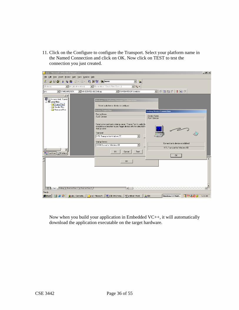
11. Click on the Configure to configure the Transport. Select your platform name in
the Named Connection and click on OK. Now click on TEST to test the connection you just created.
Now when you build your application in Embedded VC++, it will automatically download the application executable on the target hardware.

CSE 3442 Page 37 of 55
ii. Application development using Platform Builder
17. The application development involves creating a new Project. Select WCE Console
Application.

CSE 3442 Page 38 of 55
18. Select An empty project
CSE 3442 Page 39 of 55
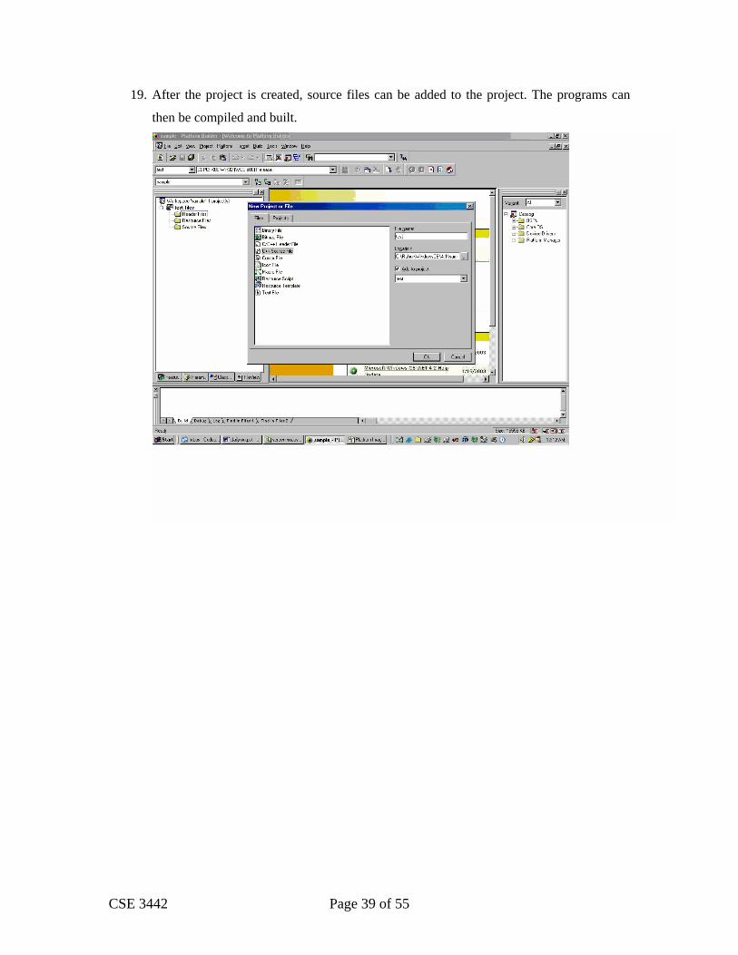
19. After the project is created, source files can be added to the project. The programs can
then be compiled and built.

CSE 3442 Page 40 of 55
c. Downloading the image
After the application has been built, we need to download the application to the target.
20. The target and the host are connected using Ethernet. Then the Remote connection is
configured. Set download and kernel transport to Ethernet. Click on configure.
CSE 3442 Page 41 of 55
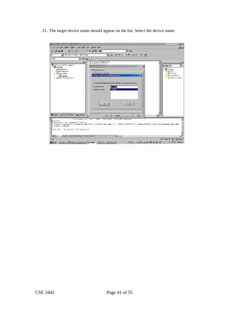
21. The target device name should appear on the list. Select the device name.
CSE 3442 Page 42 of 55
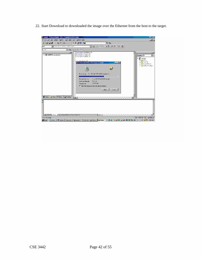
22. Start Download to downloaded the image over the Ethernet from the host to the target.

CSE 3442 Page 43 of 55
23. Run the application on the target.

CSE 3442 Page 44 of 55
7. Lab reports
After completion of each lab, the students would need to submit a lab report, which must contain:
a. A schematic diagram of the hardware
b. A brief description of the approach to the problem.
c. The source code.
The lab report would be due on the week after completing the lab.
CSE 3442 Page 45 of 55
Following is the description for the six labs that need to be implemented on Windows CE. Each
lab description follows the following format:
a. Problem statement
b. Expected time of completion.
c. Problem description.
d. Windows CE programming considerations for the lab.

CSE 3442 Page 46 of 55
8. Lab 1: Downloading the Windows CE image to the embedded PC.
a. Problem Statement:
The purpose of this lab is to understand the process of platform development on a host PC
and to download the image on the target hardware.
b. Expected time of completion:
Check your syllabus.
c. Problem Description:
Follow the steps in the section 6.
d. Windows CE programming considerations for the lab
N/A

CSE 3442 Page 47 of 55
9. Lab 2: parallel I/O using 8255.
a. Problem Statement:
The purpose of this lab is to familiarize the student with the concept of parallel I/O. The
program designs an alarm system with 4 sensor inputs (which are read from switches) and 4
LED outputs. The C program utilizes the 8255 I/O port. The alarm includes a burglar alarm,
fire alarm, and safe alarm. It also includes a 4-digit security code for arming of the alarm.
After successfully completing this lab, it will be evident how easily simple systems can be
designed and implemented.
b. Expected time of completion:
Check your syllabus.
c. Problem Description:
You are to design an alarm system that has four inputs from:
• Switch 1: the front door (FD)
• Switch 2: the back door (BD)
• Switch 3: the home safe (HS)
• Switch 4: the smoke sensor (SS)
Your alarm has four LED’s. The LED’s represent the following states:
• All LED’s off: active switch select state
• Only LED1 on: not ready state
• Only LED2 on: ready state
• Only LED 1 and LED2 on: armed state
• Only LED3 on: burglar alarm state
• Only LED4 on: safe alarm state
• Only LED3 and LED4 on: fire alarm state
Your alarm has a display, which is the terminal and LED. The terminal always displays
information regarding the active switch(s) (front door open/closed, back door open/closed,
home safe open/closed, smoke sensor on/off. The user selects which switch(s) to make
active. The alarm will ignore the inactive switch(s). The LED’s always represent the current
state of the alarm system. Every time an active switch changes the terminal must display the
status of ALL active switches, not just the active switch that changed. Inactive switches are
CSE 3442 Page 48 of 55
not displayed. The terminal will display the message only once and does not erase the
previous message.
Initially the system will be in the active switch select state (no LED on). The user is
prompted for at least one switch to be made active. If no switch is selected, the user stays in
the active switch select state. With at least one switch made active, the user moves into the
not ready state (only LED 1 is lit). If any active switch is on, the system stays in the not ready
state until all active switch(s) are off. The system moves from the not ready state to the ready
state (only LED 2 is lit) when all the active switch(s) are off. Once in the ready state, the
user is prompted for 4-digit code. If the user enters an incorrect code, the system stays in the
ready state. If the user enters the correct code, the system moves from the ready state to the
armed state (only LED 1 and 2 are lit).
This paragraph assumes that all four switches are active. If the system is in the armed state
and the front door or back door is opened, the system goes to the burglar state (only LED 3 is
lit). If the system is in the armed state and the home safe is opened, it would go to the safe
state (only LED 4 is lit). If the system is in the armed state and the smoke sensor goes on, it
would go to the fire state(only LED 3 and 4 are lit). If the system is in the fire state and the
front door, back door, home safe or smoke sensor is opened, the system stays in the fire state
until all active switches are closed. If the system is in the burglar state and the front door,
back door , home safe, or smoke sensor is opened, the system stays in the burglar state. If the
system is in the safe state and the front door, back door, home safe, or smoke sensor is
opened, the system stays in the safe state. This may seem a little confusing. For example, the
system is in the armed state with all active switches closed. The smoke sensor is opened.
The system goes to the fire state. Next the front door is opened. The smoke sensor is turned
off. Since at least one active switch is open, the system stays in the fire state. The system
goes back to the active switch select state when all active switches are closed. So when the
front door is closed the system goes back to the active switch select state. A state diagram
will be provided in the lab.
If a switch is not active, then the terminal does not display the status of that switch. That
switch has no effect on the state diagram. For example, if the smoke sensor switch is not
activated, the system can never go into the fire state. If the front door switch is not activated,
the system can go into the burglar state using the back door switch.
CSE 3442 Page 49 of 55
The user will only change switches in the not ready state, armed state, burglar state, safe
state, or fire state. Also, the inactive switch(s) may be changed in these states. The system
runs forever. You may want to add a temporary stop state to help in debugging before the
final demo.
Hardware:
The 8255 is located at I/O addresses 300 - 303, where PORT A =300, B = 301, C = 302, and
the control port = 303. Set up the PORTS on the 8255 for input from the switches on PORT
A and output to the LED’s from PORT B.
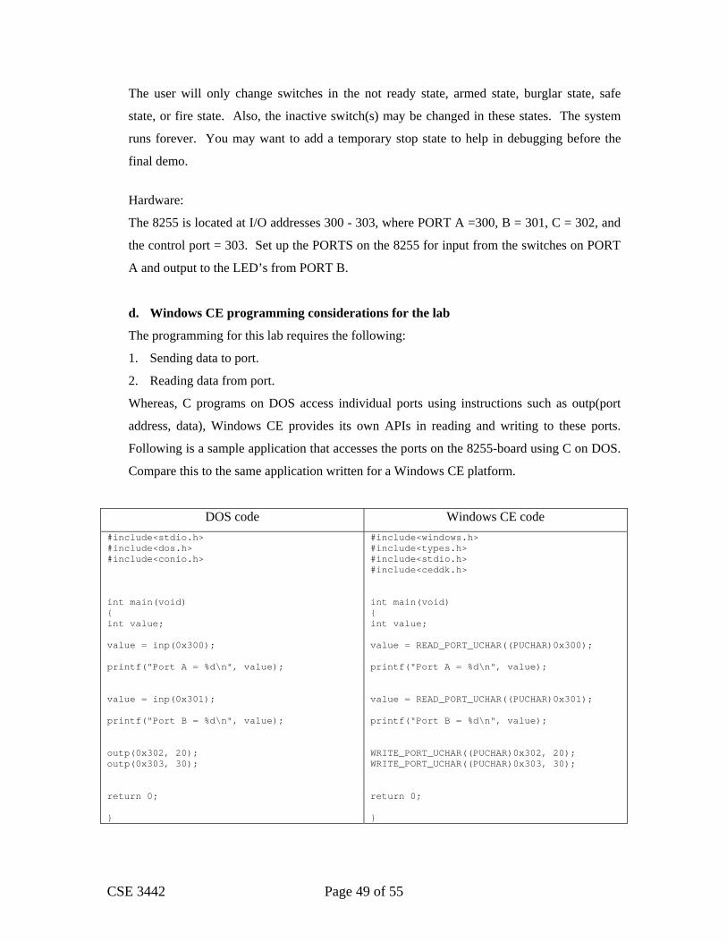
d. Windows CE programming considerations for the lab
The programming for this lab requires the following:
1. Sending data to port.
2. Reading data from port.
Whereas, C programs on DOS access individual ports using instructions such as outp(port
address, data), Windows CE provides its own APIs in reading and writing to these ports.
Following is a sample application that accesses the ports on the 8255-board using C on DOS.
Compare this to the same application written for a Windows CE platform.
DOS code Windows CE code #include<stdio.h> #include<dos.h> #include<conio.h> int main(void) { int value; value = inp(0x300); printf("Port A = %d\n", value); value = inp(0x301); printf("Port B = %d\n", value); outp(0x302, 20); outp(0x303, 30); return 0; }
#include<windows.h> #include<types.h> #include<stdio.h> #include<ceddk.h> int main(void) { int value; value = READ_PORT_UCHAR((PUCHAR)0x300); printf("Port A = %d\n", value); value = READ_PORT_UCHAR((PUCHAR)0x301); printf("Port B = %d\n", value); WRITE_PORT_UCHAR((PUCHAR)0x302, 20); WRITE_PORT_UCHAR((PUCHAR)0x303, 30); return 0; }

CSE 3442 Page 50 of 55
10. Lab 3: Analog to digital conversion
a. Problem Statement:
The purpose of this lab is work with an ADC chip and implement an ADC system.
b. Expected time of completion:
Check your syllabus.
c. Problem Description:
Part 1: Set up the ADC0804 in free running mode. Demonstrate to the GTA that the
ADC0804 works correctly before going to part 2.
Part 2: Connect the ADC0804 analog to digital (A/D) converter to the Mazidi training board.
Use port B for control, port A for data, and port C for INTR. For port B, RD = B0, WR=B1,
CS = B2. The output voltage needs to agree with a voltmeter to within two decimal places for
several different inputs. For input use a 10K pot with 5 volts across the potentiometer.
Continuously print the voltage on one line of the terminal similar to what is done with a
digital multimeter.
d. Windows CE programming considerations for the lab
The programming for this lab is similar to the last one.

CSE 3442 Page 51 of 55
11. Lab 4: Timers and Stepping motors
a. Problem Statement:
The purpose of this lab is to familiarize the student with the concepts of timers, parallel I/O,
and stepper motors. The PC will run a stepper motor with a timer chip generating the needed
times. The goal of the program is to make all the times completely dependent on the
oscillator of the training board. If the 1 MHz oscillator were replaced with a 2 MHz
oscillator, all the times should be reduced by half.
b. Expected time of completion:
Check your syllabus.
c. Problem Description:
Connect a stepper motor to the training board 8255 Port A using the driver chip. See the
schematic in the text for an example. More detail for the ULN2003A driver chip:
http://www.st.com/stonline/books/pdf/docs/5279.pdf
The 8253 timer chip on the training board has three counters. Connect the 1 MHz oscillator
on the training board to the clock input of counter 0 and the output of this counter is used as a
clock for counter 1. The output of counter 1 goes to the clock input of counter 2. The output
of counter 2 goes to Port C0 and is used to time the program.
Write a program in c that monitors the 8253 by reading Port C. This method of monitoring a
device is called polling. The stepper motor must always use a time delay created by the 8253
for all stepping operations and overall time duration. No dummy statements or operating
system calls can be used to create time delays. Also, do not print any information to the
screen that could be used as a delay.
The program works as follows. Prompt the user to enter either ‘CW’ or ‘CCW’ to turn the
motor clockwise or counter clockwise. Next, prompt the user for duration time in an even
number of seconds (2 to 60), and finally prompt the user for time between steps to be either
slow or fast. The programmer can select the fast speed, but make the time between steps
equal to 2 seconds for the slow speed. After the duration time elapses the program quits.
Use counter 0 and 1 in square wave mode and counter 2 in interrupt on terminal count mode
(mode 0).

CSE 3442 Page 52 of 55
The textbook has a sample assembly program on page 365 (3rd edition) that is useful to help
you get started.
d. Windows CE programming considerations for the lab
The programming for this lab is similar to the last one.

CSE 3442 Page 53 of 55
12. Lab 5: Interrupts
a. Problem Statement:
The purpose of this lab is to understand interrupts and to use the 8253 counter. Write a
program in c to create a 24 hour clock using the 8253 and 1 MHz oscillator on the training
board. Generate an interrupt every 0.1seconds, display the clock to a resolution of 0.1
second. Use the parallel printer port interrupt to create the clock. Use the counters of the
8253 in square wave mode to create the interrupt.
b. Expected time of completion:
Check your syllabus.
c. Problem Description:
The clock displays only hours, minutes, seconds, and tenth of a second. If the user enters ‘C’
on the keyboard, the clock changes, either from start or stop, or stop to start. If the user
enters ‘Z’ on the keyboard, the clock clears itself regardless of running or stopped. The time
on the monitor will also be cleared even if the clock is in the stop state. Finally, if a ‘Q’ is
entered, then the program quits. If the user enters ‘S’ on the keyboard, the user is prompted
for hours, minutes and seconds, and the clock continues either running or stopped depending
on how it was previously set. The clock begins not running and cleared.
After 23 hours, 59 minutes, 59 seconds, and 0.9 tenths the clock rolls over to zero. Do not
display any extra digits and do not scroll down when displaying a new clock value. Polling is
not to be used.
d. Windows CE programming considerations for the lab
The programming for this lab involves modifying the existing ISR for the parallel port
interrupt for the embedded PC.

CSE 3442 Page 54 of 55
13. Lab 6: Serial I/O over COM port
a. Problem Statement:
Write a program in C, that allows two PCs to communicate via the COM port. See example
9-4 on page 303(3nd edition) for an assembly language example.
b. Expected time of completion:
Check your syllabus.
c. Problem Description:
Step 1: Check for a key press and if a key has been pressed, get it and write it to the COM
port to be transferred. Also check for ESC to exit. Step 2: If there is no key pressed, go
check the status of the COM port. If a character was received, read it and display it on the
screen. Step 3: Go to step 1.
A line feed needs to be inserted upon detection of a carriage return. Transmitting four
carriage returns in a row causes the program to terminate. Receiving four carriage returns in a
row causes the program to terminate.
Echo the transmitted characters to the screen. Always print the receiving message on a new
line and start all received lines with the character ‘>’.
d. Windows CE programming considerations for the lab
The programming for this lab requires the following:
1. Opening a port.
2. Configuring the port.
3. Writing to the port.
4. Reading from the port.
The DOS way of achieving each of the steps above is to execute an INT structure after
populating the appropriate registers. Windows CE on the other hand uses standard APIs foe
these tasks. For example see the code below to compare the code for writing to COM port.
DOS code Windows CE code inregs.h.ah=01;
inregs.h.al=c;
inregs.x.dx=1;
int86(0x14,&inregs,&outregs);
WriteFile (hPort, &Byte, 1,
&dwNumBytesWritten, NULL);
Similarly, APIs are used for other tasks.

CSE 3442 Page 55 of 55
14. Steps to Create CE Platform
1. Create a platform (see pages 10- 25)
2. Build the platform (Choose Build Platform from the Build menu)
3. Configure SDK (see pages 26- 28)
4. Build SDK (see page 29)
5. Create a new project and add new C file to the project (see pages 37- 39)
6. Turn on the trainer kit then run the autoexec.bat file (Type autoexec in the
DOS prompt)
7. Configure Remote connection from the platform (see pages 40- 41)
8. Install the platform (see pages 30- 31)
9. Download the OS image (see pages 42- 43)
10. Restart the trainer kit then run the autoexec.bat
11. Create a new project in the embedded VC++ (see pages 32- 33)
12. Configure the platform manager for the VC++ project (see pages 34- 36)