csci 4974 / 6974 hardware reverse...
TRANSCRIPT
CSCI 4974 / 6974Hardware Reverse Engineering
Lecture 12: Non-invasive attacks

Quiz
● Memory technologies
Attack types
● Non-invasive– Any attack which does not damage the package
Non-invasive attacks
● Program/debug interfaces● Power analysis● Fault injection
Program/debug interfaces
● Several common ones in use– JTAG
– UART (serial port)
– Vendor proprietary
● May give you anything from a shell on the chip to full code execution and firmware access!
● Usually locked down, but often not too strongly
JTAG
● IEEE 1149.1 Joint Test Action Group● Standard interface for IC test ports● Standard only covers layer 2 and some of 3
– Different connectors and voltage levels in use
– A few basic registers defined in standard, others are up to the chip designer
● Can chain arbitrarily many devices end to end
JTAG
● Full duplex interface with four pins total– One control pin (TMS)
– Clock (TCK)
– Shift register data in/out (TDI, TDO)
● Optional reset line (TRST)● Nonstandard return clock (TRTCK)
JTAG
● Two registers– IR = operation to perform
– DR = data for that operation
● IR size is constant for any given chip● DR is basically a pointer, target is set by IR
– DR size varies with IR value
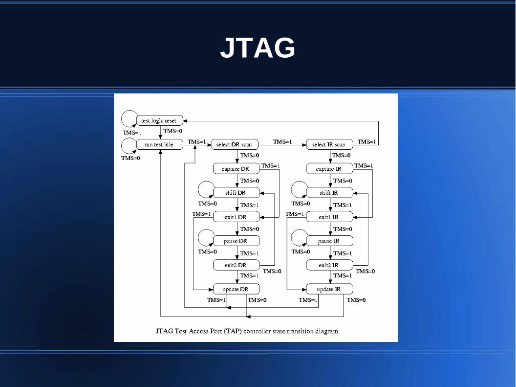
JTAG
● JTAG TAP runs a simple state machine● TMS controls state
– Idle: nothing going on
– Capture: store chip->host data in DR
– Shift: move data in/out of DR
– Update: process host->chip data
JTAG
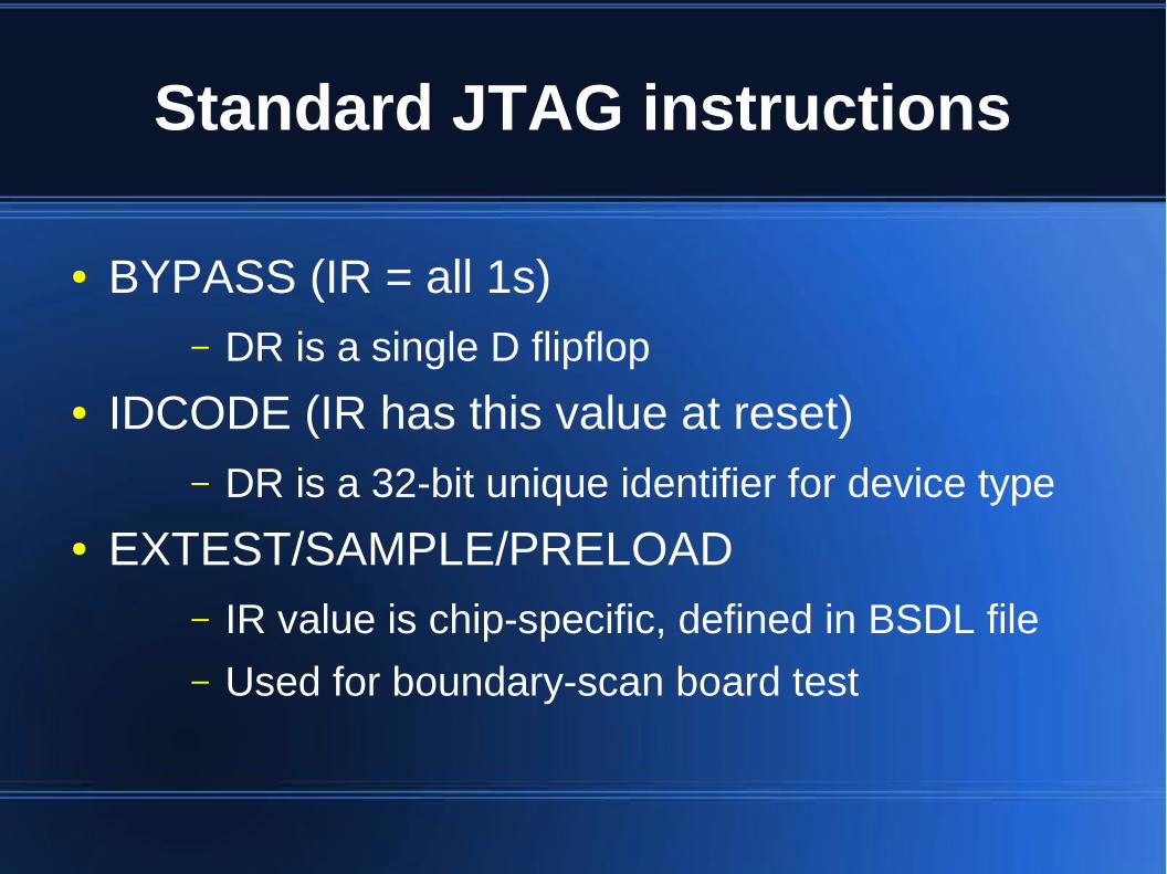
Standard JTAG instructions
● BYPASS (IR = all 1s)– DR is a single D flipflop
● IDCODE (IR has this value at reset)– DR is a 32-bit unique identifier for device type
● EXTEST/SAMPLE/PRELOAD– IR value is chip-specific, defined in BSDL file
– Used for boundary-scan board test
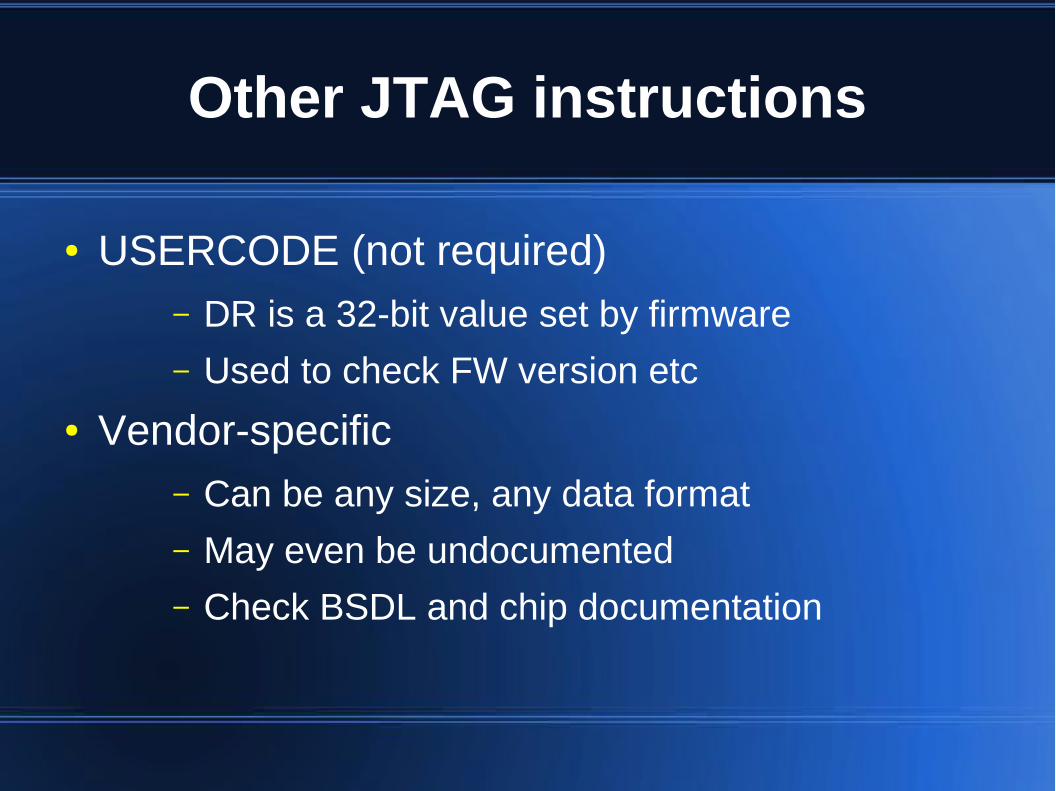
Other JTAG instructions
● USERCODE (not required)– DR is a 32-bit value set by firmware
– Used to check FW version etc
● Vendor-specific– Can be any size, any data format
– May even be undocumented
– Check BSDL and chip documentation
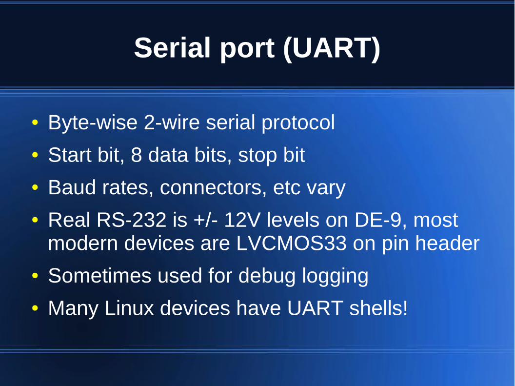
Serial port (UART)
● Byte-wise 2-wire serial protocol● Start bit, 8 data bits, stop bit● Baud rates, connectors, etc vary● Real RS-232 is +/- 12V levels on DE-9, most
modern devices are LVCMOS33 on pin header● Sometimes used for debug logging● Many Linux devices have UART shells!
Proprietary program/debug
● Read chip vendor datasheets for details● Often locked down with read-protect bit● When not disabled (or protection defeated),
typically allows– dumping of firmware flash/SRAM
– single-stepping CPU
– reading/writing CPU registers
– and more!

Power analysis
● Short-term IC power consumption is a highly complex function depending on clock speed and actual data being processed
● Very difficult to predict exactly w/o process info● But empirical data can be useful!
Simple power analysis
● Look at graphs of power usage vs time● Can typically distinguish
– Sleep vs active instruction execution
– Different types of CPU instruction (sometimes)
● Often enough for breaking sq+mult RSA

Differential power analysis
● Use more complex statistical analysis● Ex: cross-correlation between inst. with known
inputs● Look at high-frequency harmonics as signals
propagate through combinatorial logic● Can sometimes figure out actual data values in
use
Fault injection
● Cause circuit to malfunction in some way● May or may not be precisely controllable● Many different methods
– Voltage
– Temperature
– Clock/timing
– Radiation
– Semi-invasive methods (see lecture 14)
Fault injection
● Typically very low cost, minimal resources● May require detailed circuit knowledge● Common workflow:
– Decap device, analyze circuit
– Execute invasive attack
– Determine exactly where to glitch
– Non-invasive attack is more broadly usable
Goals of fault injection
● Erase lock bits but keep FW flash intact● Get CPU to skip an instruction● Compute wrong value for cryptanalysis
– See next lecture
Thermal glitching
● Heat or cool chip beyond operating limits● Hard to precisely control
– Max dT/dt is limited by package thermal mass
– Not used very often in practice for this reason
Voltage glitching
● Drop power supply below minimum● May corrupt SRAM contents● Increases RC propagation delays● Makes NVRAM erase/program unreliable● Can be precisely targeted
– One of the most common techniques
Clock/timing glitching
● Send a clock pulse that's too short– Latch intermediate value or go metastable
● Can be precisely controlled– May be hard to predict exactly when to send
glitch due to PTV variation
– One of the most common techniques
Radiation glitching
● Irradiate device with some kind of energy– X-rays
– Gamma rays
– Visible/UV/IR light (semi-invasive, needs decap)
– Neutrons, alpha particles, etc
● Particles induce photocurrents, leakage, etc● Aim beam to target portion of the die or even
single transistors. Wavelength/tech dependent.
Radiation glitching
● Some require minimal resources– Camera flash or laser pointer + microscope
– Place device near piece of high-grade uranium ore and hope for the best!
● Focused beams of esoteric particles require serious equipment (particle accelerator etc)
Data remanence
● Memory contents don't always disappear when “erased”!
SRAM data remanence
● Charge stays on poly gates briefly after power is removed
● If device doesn't clear mem on reset, may be possible to read data after loading new FW etc
DRAM data remanence
● Same phenomenon, increased capacitance means data can last longer
● Older DIMMs could even be pulled and moved to new mobo if chilled
● Modern processes leak more :(

Flash data remanence
● FTL COW means old data may stick around● Erase cycle moves most charge but not all
– Voltage glitching may enhance this!
● Partial prog/erase may allow measuring residual charge
Questions?
● TA: Andrew Zonenberg <[email protected]>
● Image credit: Some images CC-BY from:
– John McMaster <[email protected]>