cs 2511 fall 2014. uml diagram types 2 main types structure diagrams ○ class diagrams ○...
TRANSCRIPT

CS 2511
Fall 2014

UML Diagram Types
2 Main TypesStructure Diagrams
○ Class Diagrams○ Component Diagrams○ Object Diagrams
Behavior Diagrams○ Sequence Diagrams○ Use Case Diagrams

Class Diagrams
Type of static structure diagram Describes:
The structure of a system by showing the system’s classes
The class attributesThe relationships between classes

Class Node Layout
Class NameAttributes of Class(Data Members)
Operations of Class(Member Functions)

Example Class Diagram Revisitedpublic class Circle
{
private double radius;
private double area;
protected double getArea();
public void setCenter(Point);
public Point center;
}
Circleradius : doublearea : doublecenter : Point
getArea() : doublesetCenter(Point)

Visibility Specifiers
To specify the visibility of a class member (both attributes and methods) use the following before the member's name:public: +protected: #private: -package: ~

Example Class Diagram Revisitedpublic class Circle
{
private double radius;
private double area;
protected double getArea();
public void setCenter(Point);
public Point center;
}
Circle- radius: double- area: double+ center: Point
# getArea() : double+ setCenter(Point)
Class Relationships
A relationship is a general term covering the specific types of logical connections found on class and object diagrams.
We’ll look at the following:DependencyAggregationInheritance

Dependency
A very weak relationship A class depends on another class if it
manipulates objects of the other class

UML Dependency
Shape- var1 : Point
+ draw(Circle c)
Circle- radius: double- area: double+ center: Point
# getArea() : double+ setCenter(Point)

Dependency in Codepublic class Shape{
public void draw(Circle c);private Point var1;// Some other variables and methods …
}
public class Circle{
private double radius;private double area;
protected double getArea();
public void setCenter(Point);public Point center;
}
Notice that draw(Circle c) is the only reference to class Circle in Shape, so a weak relationship

Aggregation A class aggregates
another if its objects contain objects of the other class.
The aggregate class (the class with the white diamond touching it) is in some way the “whole,” and the other class in the relationship is somehow “part” of that whole.
Mailbox- messages :
ArrayList<Message>
Message*
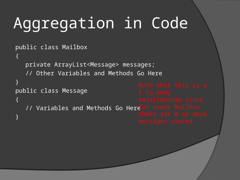
Aggregation in Codepublic class Mailbox
{
private ArrayList<Message> messages;
// Other Variables and Methods Go Here
}
public class Message
{
// Variables and Methods Go Here
}
Note that this is a 1 to many relationship since for every Mailbox there are 0 or more messages stored

Inheritance
A class inherits from another if it incorporates the behavior of the other class
Special Cases of objects of the parent class type
(Possibly) capable of exhibiting additional responsibilities

UML Inheritance
Child
+ method2()
Parent
+ method1()
Note only methods new to Child are listed in Child class (not methods inherited from Parent)

Inheritance in Code
public class Parent{
public void method1();}
public class Child extends Parent{
public void method2();}
CS 2511
Fall 2014

UML Diagram Types
2 Main Types
Structure Diagrams○ Class DiagramsClass Diagrams○ Component Diagrams○ Object Diagrams
Behavior Diagrams○ Sequence DiagramsSequence Diagrams○ Use Case Diagrams

Sequence Diagrams
A sequence diagramsequence diagram in Unified Modeling Language (UML) is a kind of interaction diagram that shows how processes operate with one another and in what order.
In Java most of the interaction between processes is done via objectsobjects, and thus a sequence diagram basically shows how objects interact with other objects.

Organization
Object Name:Class Name
:Class Name Object Name
Method Call
Method Call

Object
Each box represents an Object that is alive (i.e. it’s constructor has been called) at a particular time in the computation.
3 options to represent objects :
Object Name:Class Name
:Class Name Object Name

LifeLines
The time for which an object is “alive” i.e. still in scope (which means has not been garbage collected yet) is represented by a life line.
smallCircle:Circle

Activation Bars Activation bars are used to represent the time
when an object is calling a method.
The activation bars ends when the method that was called returns.
smallCircle:Circle
myMonitor:Display
methodCall( )
Returned from method
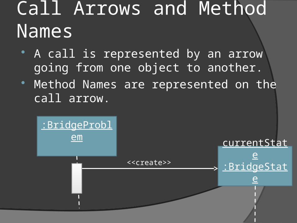
Call Arrows and Method Names A call is represented by an arrow going from
one object to another. Method Names are represented on the call
arrow.
:BridgeProblem
currentState:BridgeState<<create>>

Examples
Code :public static void main(String[] args)
{
BridgeState initialState = new BridgeState("west", "west", "west", "west", "west", 0);
BridgeState finalState = new BridgeState("east", "east", "east", "east", "east", 17);
initialState.display();
finalState.display();
}

Sequence Diagram
initialState:BridgeState
<<create>>finalState:
BridgeState
<<create>>
display()
display()
BridgeTest1.main