crosby/ip lifting clamps · crosby/ip lifting clamps a strong grip on performance, with...
TRANSCRIPT

Crosby/IPLifting ClampsA strong grip on performance, with uncompromising quality.

Copyright © 2013 The Crosby Group LLCAll Rights Reserved
ii
Table of Contents
VERTICAL LIFTING CLAMPSIPU10 - IPU10SUniversal - For lifting in any direction ...........................................................................................................................................1IP10Vertical Lifting - For Turning and Transfer ....................................................................................................................................2IPNM10 - IPNM10PNon Marring - For no damage to the material lifted .......................................................................................................................3
HORIZONTAL LIFTING CLAMPSIPHTONZ - IPHOZFor Horizontal Lifting and Transfer ................................................................................................................................................4IPHNM10 - IPH10 - IPBC - IPHGUZFor Horizontal Transfer - with Pretension System ..................................................................................................................... 5-6
BEAM CLAMPSIPTK - IPTKWFor the Transfer of Steel Beams and Attachment of Tackle Eye .......................................................................................................7IPBKZ - IPVUZFor the Transfer and Stacking of Steel Beams ..................................................................................................................................8IPBHZ - IPBSNZ - IPSTARTEC11For the Lifting and Transfer of Steel Beams............................................................................................................................... 9-10
DRUM CLAMPSIPDV - IPVKFor Moving and Transfer of 50-55 Gallon Drums ........................................................................................................................11
SHIP BUILDING CLAMPSIPBUZFor the Lifting, Transfer and Placing of Bulb Profiles onto Ship’s Hulls Perpendicularly ...........................................................................................................................12IPSU(U)ZFor Lifting, Transfer and Placement of Complete Shipsections ..............................................................................................................................................13IPBTO10For use as a Temporary Tackle Eye in Spaces Which Have Been Reinforced with HP(bulb) Profiles Such as Engine Rooms and Shipsections ..........................................................................................................................14
POSITIONING CLAMPSIPSCFor Positioning and Turning Steel Plates .....................................................................................................................................15
APPLICATION INFORMATION ............................................................................................................................... 16-17
“A Strong Grip on Performance with Uncompromising Quality.”

Copyright © 2013 The Crosby Group LLCAll Rights Reserved
1
Vertical Clamps
IPU10S: For use on Stainless Steel material.IPU10H: For use on materials with a surface hardness to 47Rc (450 HB).
Universal - For Lifting in any Direction• Available in capacities of .5 thru 30 metric tons (Higher Working Load Limits are
available upon request).• Wide variety of jaw openings available: 0” to 6.13”. • Welded alloy steel body for strength and smaller size. Forged alloy components,
where required.• Individually Proof Tested to 2 times the Working Load Limit with certification. • Company name (CrosbyIP), logo, Working Load Limit and jaw opening permanently
stamped on body.• Each product is individually serialized, with the serial number and Proof Load
test date stamped on body. Serial number is included on the test certificate with maintenance and warranty logbook.
• Available in a variety of styles:• IPU10 - Standard clamp for materials with a surface hardness to 37Rc (345HB)• IPU10J - Larger jaw opening.• IPU10S - For use with Stainless Steel material.• IPU10H - For use with materials with a surface hardness to 47Rc (450HB).
• Full 180° turning range for material transfer, turning or moving.• Lock open, lock closed ability with latch for pretension on material and then release
of material.• Optional IP-5000 Stinger assembly available (see page 17). Allows for easy connection
between the clamp and hoist hook.• Minimum WLL of 10% of Maximum WLL.• Maintenance replacement kits are available.• Manufactured by a ISO 9001 facility.• All sizes are RFID EQUIPPED.
The IPU10 vertical lifting clamp is used for the lifting, turning, moving or vertical transfer of sheet, plates, or fabrications from horizontal to vertical and down to horizontal (180°) as needed. The hinged hoisting eye allows for the clamp to place and lift the load from any direction, or with a multiple leg sling without side-loading the clamp.
IPU10SIPU10
Model IPU10
Model
WorkingLoad Limit
(t)*
IPU10StockNo.
WeightEach(lbs.)
Dimensions(in.)
Jaw A B C D E F G H J KIPU10 0.5 2701675 4.19 0 - .63 1.73 5.04 8.98 1.57 4.53 1.61 1.10 - .43IPU10 1 2701663 5.29 0 - .75 1.77 5.47 8.74 1.57 4.96 1.61 1.50 - .43IPU10 2 2701677 18.7 0 - 1.38 3.07 7.91 14.65 2.76 7.48 2.40 2.17 - .63IPU10 3 2701665 32.6 0 - 1.56 3.94 9.96 17.52 2.95 8.86 3.07 2.36 - .79IPU10 4.5 2701667 35.3 0 - 1.56 3.94 9.96 17.52 2.95 9.13 3.23 2.56 - .79IPU10 6 2701669 53.0 0 - 2.00 4.96 11.89 20.67 3.15 11.50 3.31 3.74 1.73 .79
IPU10/J 6 2702469 67.3 2.00 - 4.00 4.96 11.89 20.67 3.15 13.46 3.31 3.74 1.73 .79IPU10 9 2701671 65.0 0 - 2.00 4.96 12.80 21.93 3.15 12.20 3.62 4.13 1.73 .79
IPU10/J 9 2701673 67.2 2.00 - 4.00 4.96 12.80 22.13 3.15 14.17 3.62 4.13 1.73 .79IPU10 12 2701679 126 0 - 2.13 6.30 15.39 24.53 3.15 13.03 4.61 5.39 1.61 .98
IPU10/J 12 2701681 130 2.13 - 4.25 7.01 17.28 26.50 3.15 16.34 4.61 5.39 1.61 .98IPU10 16 2701683 159 .25 - 2.50 7.01 18.31 28.90 3.46 15.63 4.69 6.02 1.77 .98
IPU10/J 16 2701685 187 2.50 - 5.00 8.19 20.51 31.10 3.46 18.58 4.69 6.34 1.77 .98IPU10 22.5 2701687 280 .25 - 3.13 8.74 21.81 33.66 4.33 18.50 5.35 7.32 1.93 .98
IPU10/J 22.5 2701689 287 3.13 - 6.13 9.96 24.72 36.61 4.33 22.64 5.35 7.72 1.93 .98IPU10 30 2701691 337 .25 - 3.13 8.74 21.46 33.86 4.33 18.50 5.98 7.32 2.13 1.18
IPU10/J 30 2701693 364 3.13 - 6.13 9.84 24.41 36.81 4.33 22.24 5.98 7.72 2.13 1.18For stainless steel - with universal hoisting eye
IPU10/S 0.5 2702275 4.19 0 - .63 1.73 5.04 8.98 1.57 4.53 1.61 1.10 - .43IPU10/S 1 2702263 4.63 0 - .75 1.77 5.47 8.74 1.57 4.96 1.61 1.50 - .43IPU10/S 2 2702277 16.8 0 - 1.38 3.07 7.91 14.65 2.76 7.48 2.40 2.17 - .63IPU10/S 3 2702265 32.7 0 - 1.56 3.94 9.96 1.752 2.95 8.86 3.07 2.36 - .79IPU10/S 4.5 2702267 35.3 0 - 1.56 3.94 9.96 17.52 2.95 9.13 3.23 2.56 - .79IPU10/S 6 2702269 53.0 0 - 2.00 4.96 11.89 20.67 3.15 11.50 3.31 3.74 1.73 .79IPU10/S 9 2702271 65.1 0 - 2.00 4.96 12.80 21.93 3.15 12.20 3.62 4.13 1.73 .79IPU10/S 12 2702279 67.3 0 - 2.13 6.30 15.39 24.53 3.15 13.03 4.61 5.39 1.61 .98
For very hard materials - with universal hoisting eyeIPU10/H 0.5 2702175 4.19 0 - .63 1.73 5.04 8.98 1.57 4.53 1.61 1.10 - .43IPU10/H 1 2702177 16.8 0 - 1.38 3.07 7.91 14.65 2.76 7.48 2.40 2.17 - .63IPU10/H 2 2702165 32.7 0 - 1.56 3.94 9.96 17.52 2.95 8.86 3.07 2.36 - .79IPU10/H 3 2702167 35.3 0 - 1.56 3.94 9.96 17.52 2.95 9.13 3.23 2.56 - .79IPU10/H 4.5 2702169 53.0 0 - 2.00 4.96 11.89 20.67 3.15 11.50 3.31 3.74 1.73 .79IPU10/H 6 2702171 65.1 0 - 2.00 4.96 12.80 21.93 3.15 12.20 3.62 4.13 1.73 .79
K
J
G
* Design Factor based on EN 13155 and ASME B30.20.

Copyright © 2013 The Crosby Group LLCAll Rights Reserved
2
Vertical Clamps
For Vertical Lifting, Turning and Transfer• Available in capacities of .5 thru 30 metric tons (Higher Working Load Limits are available upon request).• Wide variety of jaw openings available: 0” to 6.10”.• Welded alloy steel body for strength and smaller size. Forged alloy components, where required.• Individually Proof Tested to 2 times the Working Load Limit with certification. • Company name (CrosbyIP), logo, Working Load Limit and jaw opening permanently stamped on body.• Each product is individually serialized, with the serial number and Proof Load test date stamped on
body. Serial number is included on the test certificate with maintenance and warranty logbook.• Available in a variety of styles:
• IP10 - Standard clamp for materials with a surface hardness to 37Rc (345 HB).• IP10J - Larger jaw opening.• IP10S - For use with Stainless Steel material.• IP10H - For use with materials with a surface hardness to 47Rc (450 HB).
• Full 180° turning range for material transfer, turning or moving.• Lock open, lock closed ability with latch for pretension on material and then release of material.• Optional IP-5000 Stinger assembly available (see page 17). Allows for easy connection between the clamp
and hoist hook.• Minimum WLL of 10% of Maximum WLL.• Maintenance replacement kits are available.• Manufactured by a ISO 9001 facility.• All sizes are RFID EQUIPPED.
The IP10 vertical lifting clamp is used for the lifting, turning, moving or vertical transfer of sheet, plates, or fabrications from horizontal to vertical and down to horizontal (180°) as needed. Usually used as a single point pick or when used with a spreader beam with multiple vertical drop lines.
IP10
Model IP10
Model
WorkingLoad Limit(t)*
IP10StockNo.
WeightEach(lbs.)
Dimensions(in.)
Jaw A B C D E F G H J KIP10 0.5 2701674 3.97 0 - .63 1.73 5.04 8.15 1.18 4.53 1.61 1.10 - .39IP10 1 2701662 4.85 0 - .75 1.77 5.47 8.46 1.18 4.96 1.61 1.50 - .39IP10 2 2701676 16.8 0 - 1.38 3.07 7.91 13.23 2.76 7.48 2.40 2.17 - .63IP10 3 2701664 30.4 0 - 1.56 3.94 9.96 17.17 2.95 8.86 3.07 2.36 - .79IP10 4.5 2701666 33.1 0 - 1.56 3.94 9.96 17.17 2.95 9.13 3.23 2.56 - .79IP10 6 2701668 51.9 0 - 2.00 4.96 11.89 20.28 3.15 11.50 3.31 3.74 1.57 .79
IP10/J 6 2701705 62.9 2.00 - 4.00 4.96 11.89 20.28 3.15 13.46 3.31 3.74 1.57 .79IP10 9 2701670 60.7 0 - 2.00 4.96 12.80 21.65 3.15 12.20 3.62 4.13 1.73 .79
IP10/J 9 2701672 62.9 2.00 - 4.00 4.96 12.80 21.85 3.15 14.17 3.62 4.13 1.73 .79IP10 12 2701678 108 0 - 2.13 6.30 15.39 22.83 3.16 13.03 4.61 5.39 1.61 .98
IP10/J 12 2701680 128 2.13 - 4.25 7.01 17.28 24.80 3.15 16.34 4.61 5.39 1.61 .98IP10 16 2701682 150 .25 - 2.50 7.01 18.31 27.17 3.46 15.63 4.69 6.02 1.93 .98
IP10/J 16 2701684 199 2.50 - 5.00 8.19 20.51 29.37 3.46 18.58 4.69 6.34 1.93 .98IP10 22.5 2701686 238 .25 - 3.13 8.74 21.81 31.50 4.33 18.50 5.35 7.32 1.93 .98
IP10/J 22.5 2701688 243 3.13 - 6.10 9.96 24.72 34.65 4.33 22.64 5.35 7.72 1.93 .98IP10 30 2701690 327 .25 - 3.13 8.74 21.46 31.50 4.33 18.50 5.98 7.32 2.13 1.18
IP10/J 30 2701692 335 3.13 - 6.10 9.84 24.41 34.65 4.33 22.24 5.98 7.72 2.13 1.18For stainless steel - with fixed hoisting eye
IP10/S 0.5 2702274 3.97 0 - .63 1.73 5.04 8.15 1.18 4.53 1.61 1.10 - .39IP10/S 1 2702262 4.41 0 - .75 1.77 5.47 8.46 1.18 4.96 1.61 1.50 - .39IP10/S 2 2702276 15.0 0 - 1.38 3.07 7.91 13.23 2.76 7.48 2.40 2.17 - .63IP10/S 3 2702264 30.5 0 - 1.56 3.94 9.96 17.17 2.95 8.86 3.07 2.36 - .79IP10/S 4.5 2702266 33.1 0 - 1.56 3.94 9.96 17.17 2.95 9.13 3.23 2.56 - .79IP10/S 6 2702268 51.9 0 - 2.00 4.96 11.89 20.67 3.15 11.50 3.31 3.74 1.57 .79IP10/S 9 2702270 60.7 0 - 2.00 4.96 12.80 21.93 3.15 12.20 3.62 4.13 1.73 .98IP10/S 12 2702278 108 0 - 2.13 6.30 15.39 24.53 3.15 13.03 4.61 5.39 1.61 .98
For very hard materials - with fixed hoisting eyeIP10/H 0.5 2702174 3.97 0 - .63 1.73 5.04 8.15 1.18 4.53 1.61 1.10 - .39IP10/H 1 2702176 15.0 0 - 1.38 3.07 7.91 13.23 2.76 7.48 2.40 2.17 - .39IP10/H 2 2702164 30.4 0 - 1.56 3.94 9.96 17.17 2.95 8.86 3.07 2.36 - .63IP10/H 3 2702166 33.1 0 - 1.56 3.94 9.96 17.17 2.95 9.13 3.23 2.56 - .79IP10/H 4.5 2702168 51.9 0 - 2.00 4.96 11.89 20.28 3.15 11.50 3.31 3.74 1.57 .79IP10/H 6 2702170 60.7 0 - 2.00 4.96 12.80 21.65 3.15 12.20 3.62 4.13 1.73 .98
* Design Factor based on EN 13155 and ASME B30.20.

Copyright © 2013 The Crosby Group LLCAll Rights Reserved
3
Vertical Clamps
For use in almost all sectors of industry where during the lift or transfer, no damage to the
material is permitted.• Available in capacities of .5 , 1 and 2 metric tons.• Wide variety of jaw openings available: 0” to 1.50” • Welded alloy steel body for strength and smaller size. Forged
alloy components, where required.• Individually Proof Tested to 2 times the Working Load Limit
with certification. • Company name (CrosbyIP), logo, Working Load Limit and jaw
opening permanently stamped on body.• Each product is individually serialized, with the serial number
and Proof Load test date stamped on body. Serial number is included on the test certificate with maintenance and warranty logbook.
• Full 180° turning range for material transfer, turning or moving.• Lock open, lock closed ability with latch for pretension on
material and then release of material.• Optional IP-5000 Stinger assembly available (see page 17). Allows
for easy connection between the clamp and hoist hook.• Material must be clean and dry.• Maintenance replacement kits are available.• Manufactured by a ISO 9001 facility.• All sizes are RFID EQUIPPED.
The IPNM10 vertical lifting clamp is used for the lifting, turning, moving or vertical transfer of sheet, plates, or fabrications from horizontal to vertical and down to horizontal (180°) as needed without marring the surface of the material. Materials such as aluminum, stainless steel, painted materials, aircraft skins, composite material, glass, plastic, etc., can be lifted without marring.Will NOT mar, or scratch the material surface.
The IPNM10P vertical lifting clamp is used for the lifting, turning, moving or vertical transfer of sheet, plates, or fabrications from horizontal to vertical and down to horizontal (180°) as needed without marring the surface of the material. Materials such as aluminum, stainless steel, painted materials, aircraft skins, composite material, glass, plastic, etc., can be lifted without marring. The protective cover reduces the risk of damage to surrounding plates. Will NOT mar, or scratch the material surface.
IPNM10 IPNM10P
Model
WorkingLoad Limit
(t)*
IPNM10StockNo.
WeightEach(lbs.)
Dimensions(in.)
Jaw A B C D E F G H KIPNM10 .5 2703276 5.51 0 - .38 2.91 5.87 8.07 1.57 5.04 2.36 1.50 .43
IPNM10N .5 2703811IPNM10N 1 2703738 9.70 0 - .79 4.33 8.23 10.63 1.18 7.24 3.15 2.20 .39IPNM10 2 2703442 32.0 0 - 1.50 6.02 10.16 15.59 2.76 7.72 3.94 6.34 .63
With protection capIPNM10/P .5 2703278 6.2 0 - .38 3.23 6.18 8.39 1.57 5.71 2.68 1.89 .43IPNM10/P 1 2703279 9.9 0 - .75 3.82 7.68 10.55 1.18 8.07 3.23 2.36 0.39
With larger jaw openingIPNM10/J 1 2703312 12.1 .81 - 1.44 3.39 7.72 10.43 1.18 6.97 3.15 2.01 .39
Model IPNM10
* Design Factor based on EN 13155 and ASME B30.20.

Copyright © 2013 The Crosby Group LLCAll Rights Reserved
4
Horizontal Clamps
For Horizontal Lift and Transfer - with Pretension System
• Available in capacities of .5 thru 12 metric tons.• Jaw openings available: 0” to 4.75”. • Welded alloy steel body for strength and smaller size. Forged alloy
components, where required.• Individually Proof Tested to 2 times the Working Load Limit
with certification. • Company name (CrosbyIP), logo, Working Load Limit and jaw
opening permanently stamped on body.• Each product is individually serialized, with the serial number and
Proof Load test date stamped on body. Serial number is included on the test certificate with maintenance and warranty logbook.
• Maintenance replacement parts are available.• Manufactured by a ISO 9001 facility.• All sizes are RFID EQUIPPED.
The IPHNM10 horizontal lifting clamps have a pretension feature that allows the user to attach the clamps to the material for horizontal lifting and transfer of non-sagging material. To be used where material surface must not be damaged. These clamps must be used in pairs or more.
The IPH10 horizontal lifting clamps with spring loaded tension have a pretension feature that allows the user to attach the clamps to the material for horizontal lifting and transfer of non-sagging material. These clamps must be used in pairs or more.
IPHNM10 IPH10
A
B
C
D
E
G
F
Model
WorkingLoad Limit
(Per Pair)(t)*
IPHNM10StockNo.
WeightEach(lbs.)
Dimensions(in.)
Jaw A B C D E F G H J KIPHNM10 .5 2703287 4.41 0 - .75 3.19 .87 3.23 .63 3.98 6.30 2.91 .47 2.36IPHNM10 1 2703288 7.70 0 - 1.38 3.66 1.18 3.62 .63 4.06 6.46 2.91 .47 2.36IPHNM10 2 2703290 16.5 0 - 1.19 5.47 1.18 5.16 .87 6.54 9.65 3.94 .79 2.91
IPHNM10/J 2 2703291 17.6 1.19 - 2.38 6.65 1.18 5.16 .87 6.54 9.65 3.94 .79 2.91
Model IPHNM10
* Design Factor based on EN 13155 and ASME B30.20.
Model
WorkingLoad Limit
(Per Pair)(t)*
IPH10StockNo.
WeightEach(lbs.)
Dimensions(in.)
Jaw A B C E F G H J KIPH10 .5+ 2703297 3.97 0 - .75 3.39 .47 .63 4.06 5.91 2.36 .47 1.06IPH10 1+ 2703298 5.50 0 - 1.38 3.94 .63 .63 4.06 5.91 2.36 .47 1.22IPH10 2 2703522 12.1 0 - 2.38 4.61 .63 .87 4.29 10.08 4.33 .79 1.57IPH10 3 2703523 16.5 0 - 2.38 4.61 .79 1.02 4.29 10.47 4.72 .79 1.89IPH10 4.5 2703524 23.1 0 - 2.38 5.20 .98 1.18 4.09 11.02 5.12 .79 1.89IPH10 6 2703525 28.6 0 - 2.38 5.63 .98 1.42 4.84 12.60 5.12 .79 1.89IPH10 9 2703526 40.8 0 - 2.38 6.18 1.18 1.69 5.24 12.99 5.51 .98 2.44IPH10 12 2703527 47.4 0 - 2.38 6.77 1.18 1.85 5.55 13.90 5.91 .98 2.44
With larger jaw openingIPH10/J 3 2703533 19.8 2.38 - 4.75 6.97 .79 1.02 4.29 10.47 4.72 .79 1.89IPH10/J 4.5 2703534 26.5 2.38 - 4.75 7.56 .98 1.18 4.09 11.02 5.12 .79 1.89IPH10/J 6 2703535 33.1 2.38 - 4.75 7.99 .98 1.42 4.84 12.60 5.12 .79 1.89IPH10/J 9 2703536 45.2 2.38 - 4.75 8.54 1.18 1.69 5.24 12.99 5.51 .98 2.44IPH10/J 12 2703537 52.9 2.38 - 4.75 9.13 1.18 1.85 5.55 13.90 5.91 .98 2.44
Model IPH10 and IPH10/J: With Spring Loaded Tension, Magnets and Handle
* Design Factor based on EN 13155 and ASME B30.20. + No handle or magnets.

Copyright © 2013 The Crosby Group LLCAll Rights Reserved
5
Horizontal Clamps
For Horizontal Lifting and Transfer• Available in capacities of .5 thru 25 metric tons.• Wide variety of jaw openings available: 0” to 4-3/4”. • Welded alloy steel body for strength and smaller size. Forged alloy
components, where required.• Individually Proof Tested to 2 times the Working Load Limit
with certification. • Company name (CrosbyIP), logo, Working Load Limit and jaw opening
permanently stamped on body.• Each product is individually serialized, with the serial number and Proof
Load test date stamped on body. Serial number is included on the test certificate with maintenance and warranty logbook.
• Maintenance replacement parts are available.• Manufactured by a ISO 9001 facility.• All sizes are RFID EQUIPPED.
The IPHOZ horizontal lifting clamp is to be used for lifting and transferring, in the horizontal position, of thin sheet and other materials that will sag or bend when lifted. These clamps must be used in pairs or more.
The IPH10E clamps are suitable for the lifting and transfer in horizontal position of non-sagging steel plates. The clamp is equipped with a handle for simple and easy placement onto the plate. These clamps must be used in pairs or more.
IPH10E IPHOZ
Model IPH10E: Jaw opening range 0 to 4-3/4”
Model
Working Load Limit
(Per Pair)(t)*
IPHOZStockNo.
WeightEach(lbs.)
Dimensions(in.)
Jaw A B C E F G H J KIPHOZ 0.75 2705401 6.60 0 - 1.19 3.70 .63 .63 2.76 4.65 3.19 .47 .47IPHOZ 1.5 2705402 12.1 0 - 1.75 5.24 .63 .87 4.92 7.56 3.94 .63 .47IPHOZ 3 2705403 17.6 0 - 1.75 5.39 .79 1.02 4.92 7.87 4.72 .79 .39IPHOZ 4.5 2705404 18.7 0 - 1.75 5.43 .98 1.18 4.96 8.66 4.72 .79 .39
With larger jaw openingIPHOZ 6 2705405 34.2 0 - 2.38 6.73 1.18 1.42 5.31 9.25 5.12 .79 .79IPHOZ 9 2705406 45.2 0 - 2.38 8.31 1.18 1.69 6.54 10.87 6.30 .98 .79IPHOZ 12 2705407 83.8 0 - 2.38 8.54 1.57 1.85 6.61 11.57 7.48 .98 .75IPHOZ 15 2705408 83.8 0 - 2.38 8.66 1.57 1.85 7.20 12.48 9.84 .98 .87
Model
Working Load Limit
(Per Pair)(t)*
IPHOZStockNo.
WeightEach(lbs.)
Dimensions(in.)
Jaw A B C E F G H J K LIPH10E 2 2703542 24.3 0-2.36 4.61 .63 .87 4.29 10.1 4.33 .79 1.57 .35IPH10E 3 2703543 33.1 0-2.36 4.61 .79 1.02 4.29 10.5 4.72 .79 1.89 .43IPH10E 4.5 2703544 46.3 0-2.36 5.20 .98 1.18 4.09 11.0 5.12 .79 1.89 .47IPH10E 6 2703545 57.3 0-2.36 5.62 .98 1.42 4.84 12.6 5.12 .79 1.89 .55IPH10E 9 2703546 81.6 0-2.36 6.18 1.18 1.69 5.24 13.0 5.51 .98 2.44 .63IPH10E 12 2703547 94.8 0-2.36 6.77 1.18 1.85 5.55 13.9 5.91 .98 2.44 .67
With larger jaw openingIPH10JE 3 2703553 39.7 2.36-4.72 6.97 .79 1.02 4.29 10.5 4.72 .79 1.89 .43IPH10JE 4.5 2703554 52.9 2.36-4.72 7.56 .98 1.18 4.09 11.0 5.12 .79 1.89 .47IPH10JE 6 2703555 66.1 2.36-4.72 7.99 .98 1.42 4.84 12.6 5.12 .79 1.89 .55IPH10JE 9 2703556 90.4 2.36-4.72 8.54 1.18 1.69 5.24 13.0 5.51 .98 2.44 .63IPH10JE 12 2703557 106 2.36-4.72 9.13 1.18 1.85 5.55 13.9 5.91 .98 2.44 .67
Model IPHOZ: Jaw opening range 0 to 2-3/8”
* Design Factor based on EN 13155 and ASME B30.20.
* Design Factor based on EN 13155 and ASME B30.20.
E
B
G
F
AC
K
100%
0°
75%
50%
600
1200
900100%
0°15°15°
100%
0°
75%
50%
600
1200
900100%
0°15°15°

Copyright © 2013 The Crosby Group LLCAll Rights Reserved
6
Horizontal Clamps
For Horizontal Transfer - with Pretension System• Available in capacities of 1 thru 4.5 metric tons.• Jaw openings available: 0” to 1.56”. • Welded alloy steel body for strength and smaller size. Forged alloy
components, where required.• Individually Proof Tested to 2 times the Working Load Limit
with certification. • Company name (CrosbyIP), logo, Working Load Limit and jaw opening
permanently stamped on body.• Each product is individually serialized, with the serial number and
Proof Load test date stamped on body. Serial number is included on the test certificate with maintenance and warranty logbook.
• Maintenance replacement parts are available.• Manufactured by a ISO 9001 facility.• All sizes are RFID EQUIPPED.
The IPBC horizontal lifting clamps have a pretension feature that allows the user to attach the clamps to the material for horizontal lifting and transfer of sagging and non-sagging material. These clamps may also be used to handle material that will be used in shears, bending and rolling machines or other fabrication equipment. May also be used for turning beams from the “H” into the “I” position.
The IPHGZ, IPHGUZ horizontal lifting clamps have a pretension locking feature that allows the user to attach the clamps to the material for horizontal lifting and transfer of sagging and non-sagging material. These clamps may also be used to handle material that will be used in shears, bending and rolling machines or other fabrication equipment. May also be used to move and lift structural shapes such as I-Beams, H-beams etc.
IPBC IPHGUZ
Model
WorkingLoad Limit(t)*
StockNo.
WeightEach(lbs.)
Dimensions(in.)
Jaw A B C D E F G J KIPHGUZ 1.5 2705455 19.8 0 - 1.00 4.33 9.13 11.30 2.76 5.47 3.54 .79 .63IPHGUZ 3.0 2705456 43.9 0 - 1.56 4.69 9.96 13.70 2.95 6.89 4.72 .98 .79IPHGUZ 4.5 2705457 66.1 0 - 1.56 4.69 11.85 14.57 3.15 6.89 6.10 1.18 1.73
Fixed Hoisting EyeIPHGZ .75 2705451 8.82 0 - 1.00 3.23 5.83 8.11 1.97 3.90 3.86 .47 .87IPHGZ 1.5 2705452 16.1 0 - 1.00 4.33 7.87 9.84 1.97 4.65 3.54 .79 1.10IPHGZ 3.0 2705453 27.1 0 - 1.56 4.72 8.94 12.01 2.76 5.83 4.72 .98 1.26IPHGZ 4.5 2705454 55.1 0 - 1.56 4.72 11.18 15.00 2.76 7.13 6.10 1.18 1.57
Model IPHGUZ: Universal Lifting EyeModel IPHGZ: Fixed Hoisting Eye
* Design Factor based on EN 13155 and ASME B30.20.
Model
Working Load Limit(t)*
IPBCStockNo.
WeightEach(lbs.)
Dimensions(in.)
Jaw A B C E F G H J KIPBC 1 2700410 7.72 0 - .75 5.20 2.05 1.02 2.95 7.28 1.42 .63 7.17IPBC 2 2700411 14.3 0 - 1.00 5.98 2.44 1.18 3.23 8.27 1.93 .79 8.58IPBC 3 2700412 18.8 0 - 1.00 6.18 2.60 1.18 3.23 8.27 2.24 .79 8.86
Model IPBC
* Design Factor based on EN 13155 and ASME B30.20.
J

Copyright © 2013 The Crosby Group LLCAll Rights Reserved
7
Horizontal Clamps
• Available in capacities of 3 thru 12 metric tons.• Wide variety of jaw openings available: 0 to 16.5”.• Welded alloy steel body for strength and smaller size. Forged alloy components,
where required.• Individually Proof Tested to 2 times the Working Load Limit with certification. • Company name (CrosbyIP), logo, Working Load Limit and jaw opening permanently
stamped on body.• Each product is individually serialized, with the serial number and Proof Load
test date stamped on body. Serial number is included on the test certificate with maintenance and warranty logbook.
• Manufactured by a ISO 9001 facility.• All sizes are RFID EQUIPPED.
For the Lifting and Transfer of Bundles of Plates
The IPPE is suitable for the lifting and transfer of bundles of non-sagging steel plates in horizontal position.The jaw opening can be easily adjusted. Raising the handle opens the clamp. This facilitates the easy and quick placing or removing of the clamp.
Model IPPE
IPPE
Model
IPPEStock No.
Working Load Limit (Per Pair)
(t)*
Weight Each (lbs.)
Dimensions(in.)
Jaw A B C D E F G H J K
3 IPPEB 2700501 3.0 23.1 0 – 7.13 7.64 10.08 .79 1.02 2.60 .79 5.51 2.99 .59
3 IPPED 2700502 3.0 28.7 0 – 11.75 7.64 14.80 .79 1.02 2.60 .79 5.51 2.99 .59
3 IPPEH 2700503 3.0 30.9 0 – 16.50 7.64 19.53 .79 1.02 2.60 .79 5.51 2.99 .59
6 IPPEH 2700506 6.0 50.7 0 – 16.50 8.94 20.31 .98 1.18 4.02 .79 6.30 2.99 .51
9 IPPEH 2700509 9.0 68.3 0 – 16.50 10.63 22.28 .98 1.34 4.80 .79 7.48 2.99 .8312 IPPEH 2700512 12.0 114.6 0 – 16.50 11.50 23.15 1.18 1.57 5.24 .98 7.87 3.82 .71
* Design Factor based on EN 13155 and ASME B30.20.

Copyright © 2013 The Crosby Group LLCAll Rights Reserved
8
Beam Clamps
For the Transfer and Stacking of Steel Beams• Available in capacities of .75 thru 3.75 metric tons.• Wide variety of jaw openings available: 0” to 1.13”. • Welded alloy steel body for strength and smaller size. Forged
alloy components, where required.• Individually Proof Tested to 2 times the Working Load Limit
with certification. • Company name (CrosbyIP), logo, Working Load Limit and jaw
opening permanently stamped on body.• Each product is individually serialized, with the serial number
and Proof Load test date stamped on body. Serial number is included on the test certificate with maintenance and warranty logbook.
• Optional IP-5000 Stinger assembly available (see page 402). Allows for easy connection between the clamp and hoist hook.
• Minimum WLL of 10% of Maximum WLL.• Maintenance replacement parts are available.• Manufactured by a ISO 9001 facility.• All sizes are RFID EQUIPPED.
The IPBKZ beam clamp is used for lifting, transfer and stacking of H-Beams. An over-center hoist eye allows for the beam flange to remain vertical. This series of clamps can be used in the vertical and horizontal moving, transfer and stacking of different types of structural designs, such as H-Beams, angles, etc, depending on the application desired.
The IPVZ / IPVUZ beam clamp is used for vertical lift and transfer of angle iron and other loads that have only a small gripping area for the clamp (“U” has universal hoisting eye).This series of clamps can be used in the vertical and horizontal moving, transfer and stacking of different types of structural designs, such as I-Beams, H-beams, angles, etc, depending on the application desired.
K
G
B
A
C
F
E
H
D
IPBKZ IPVUZ
Model
WorkingLoad Limit(t)*
StockNo.
WeightEach(lbs.)
Dimensions(in.)
Jaw A B C D E F G H KIPVUZ 0.75 2705146 5.07 0 - .63 1.77 5.43 9.37 1.18 5.04 1.61 1.46 .39IPVUZ 1.5 2705147 19.6 0 - .75 3.07 7.91 14.88 2.76 7.87 2.40 2.83 .63
Fixed Hoisting EyeIPVZ 0.75 2705096 4.63 0 - .63 1.02 5.04 8.15 1.18 4.53 1.61 1.18 .39IPVZ 1.5 2705097 13.7 0 - .75 2.36 7.87 13.35 2.76 7.09 2.05 1.97 .63
Model IPVUZ: Universal Hoisting EyeModel IPVZ: Fixed Hoisting Eye
* Design Factor based on EN 13155 and ASME B30.20.
Model
Working Load Limit(t)*
IPBKZStockNo.
WeightEach(lbs.)
Dimensions(in.)
Jaw A B C D E F G H JIPBKZ 0.75 2705780 7.72 .19 - .63 1.69 5.20 7.56 1.77 4.45 1.85 1.50 .39IPBKZ 1.5 2705781 15.4 .19 - 1.00 2.44 8.27 11.81 2.76 6.42 2.40 1.97 .63IPBKZ 3.75 2705782 34.2 .19 - 1.13 2.95 10.24 16.34 3.94 7.95 3.07 2.05 .79
Model IPBKZ
* Design Factor based on EN 13155 and ASME B30.20.J
G
B
H AF
E
C
D

Copyright © 2013 The Crosby Group LLCAll Rights Reserved
9
Beam Clamps
For the Lifting and Transfer of Steel Beams• Available in capacities of .75 thru 12 metric tons.• Wide variety of jaw openings available: 0” to 2”.• Welded alloy steel body for strength and smaller size. Forged alloy
components, where required.• Individually Proof Tested to 2 times the Working Load Limit with certification. • Company name (CrosbyIP), logo, Working Load Limit and jaw opening
permanently stamped on body.• Each product is individually serialized, with the serial number and Proof
Load test date stamped on body. Serial number is included on the test certificate with maintenance and warranty logbook.
• Maintenance replacement parts are available.• Manufactured by a ISO 9001 facility.• All sizes are RFID EQUIPPED.
The IPBHZ beam clamp is used for horizontal lifting and transfer of steel beams. The base is slotted to allow the clamps to be used from end of beams as well as from the flange. This series of clamps can be used in the vertical and horizontal moving, transfer and stacking of different types of structural designs, such as I-Beams, H-beams, angles, etc, depending on the application desired.
The IPBSNZ beam clamp is used for lifting, transfer and stacking. Offset hoisting eye allows for level lifts of I-Beams, also for lifting fabrications and ship sections. This series of clamps can be used in the vertical and horizontal moving, transfer and stacking of different types of structural designs, such as I-Beams, depending on the application desired.
IPBHZ IPBSNZ
Model
Working Load Limit(t)*
IPBHZStockNo.
WeightEach(lbs.)
Dimensions(in.)
Jaw A B C D E F G J KIPBHZ 0.75 2705461 6.61 0 - 1.00 1.57 5.83 8.66 1.97 5.12 2.72 1.30 .87IPBHZ 1.5 2705462 13.2 0 - 1.00 2.36 7.87 10.04 1.97 6.02 2.87 1.38 1.10IPBHZ 3 2705463 23.2 0 - 1.56 3.15 8.94 12.80 2.76 7.40 4.41 1.50 1.26IPBHZ 4.5 2705464 55.2 0 - 1.56 4.41 11.18 16.26 2.76 9.88 4.57 3.15 1.57IPBHZ 12 2705467 92.6 0 - 1.56 4.92 18.35 19.29 3.54 12.48 3.54 3.54 1.85
Model IPBHZ
* Design Factor based on EN 13155 and ASME B30.20.
Model
Working Load Limit(t)*
IPBSNZStockNo.
WeightEach(lbs.)
Dimensions(in.)
Jaw A B C D E F G H J KIBPSNZ 1.5 2705925 30.9 0 - 1.25 3.94-10.63 11.97 18.90 2.76 12.56 1.85 .63 6.50 5.83IPBSNZ 3 2705926 48.5 0 - 1.56 3.94-12.99 13.86 19.45 2.95 16.06 2.20 .79 8.15 7.17IPBSNZ 4.5 2705927 67.2 0 - 2.00 3.94-14.17 16.54 24.80 2.95 17.99 2.20 .79 9.84 7.40
Model IPBSNZ
* Design Factor based on EN 13155 and ASME B30.20.

Copyright © 2013 The Crosby Group LLCAll Rights Reserved
10
Beam Clamps
For the Transfer of Steel Beams and Attachment of Tackle Eye• Available in capacities of 2 thru 25 metric tons.• Wide variety of jaw openings available: 3” to 40”. • Welded alloy steel body for strength and smaller size. Forged alloy components, where required.• Individually Proof Tested to 2 times the Working Load Limit with certification. • Company name (CrosbyIP), logo, Working Load Limit and jaw opening permanently stamped on body.• Each product is individually serialized, with the serial number and Proof Load test date stamped
on body. Serial number is included on the test certificate with maintenance and warranty logbook.• Maintenance replacement parts are available.• Manufactured by a ISO 9001 facility.• All sizes are RFID EQUIPPED.
This IPTK series beam clamp is suitable for use as a temporary tackle eye for a beam.
IPTK
IPTK
IPTKWModel
WorkingLoad Limit(t)*
StockNo.
WeightEach(lbs.)
Dimensions(in.)
Jaw A C D E F H J KIPTK 2 2700996 13.2 3.00 - 7.50 A + 3.13 4.92 2.95 - .98 - .79IPTK 3 2700997 14.3 3.00 - 7.50 A + 3.13 4.92 2.95 - .98 - .79IPTK 4 2700998 18.7 5.88 - 11.25 A + 4.00 4.92 2.95 - 1.38 - .79IPTK 5 2700994 24.3 4.75 - 13.75 A + 7.67 4.92 2.95 - 1.57 - .79IPTK 10 2700970 68.3 11.75 - 19.70 A + 11.75 6.98 2.91 - 1.57 - 1.18IPTK 25 2702999 496 18.00 - 40.00 A + 8.66 19.69 4.92 - 2.99 - 1.77
Without Hoisting EyeIPTKW 2 2700966 8.82 3.00 - 7.50 A + 3.13 4.92 - 1.10 .98 - -IPTKW 3 2700967 9.92 3.00 - 7.50 A + 3.13 4.92 - 1.10 .98 - -IPTKW 4 2700968 13.9 5.88 - 11.25 A + 4.00 4.92 - 1.30 1.38 - -IPTKW 5 2700969 19.4 4.75 - 13.75 A + 7.67 4.92 - 1.30 1.57 - -
With Improved Hinged Hoisting EyeIPTKU 2 2707996 12.8 2.95 - 7.48 A + 3.94 4.76 2.99 - .87 3.90 .75IPTKU 3 2707997 14.3 2.95 - 7.48 A + 3.94 4.76 3.50 - .87 4.80 .87IPTKU 4 2707998 21.8 4.72 - 11.02 A + 5.91 5.51 3.50 - 1.57 4.80 .87IPTKU 5 2707994 26.4 4.72 - 13.78 A + 6.89 5.51 3.50 - 1.57 4.80 .87IPTKU 10 2707970 83.8 7.87 - 18.11 A + 11.81 7.87 4.13 - 2.36 5.98 1.02
With Optional Double Locking DeviceIPTKU/D 2 2709996 12.8 2.95 - 7.48 A + 3.94 6.50 3.50 - .87 3.90 .75IPTKU/D 3 2709993 14.3 2.95 - 7.48 A + 3.94 6.50 3.50 - .87 4.80 .87IPTKU/D 4 2709995 21.8 4.72 - 11.02 A + 5.91 7.28 3.50 - 1.57 4.80 .87IPTKU/D 5 2709994 26.4 4.72 - 13.78 A + 6.89 7.28 3.50 - 1.57 4.80 .87IPTKU/D 10 2709970 83.8 7.87 - 18.11 A + 11.81 9.84 4.13 - 2.36 5.98 1.02
Model IPTK: With Hoisting EyeModel IPTKW: Without Hoisting EyeModel IPTKU: With Hinged Hoisting Eye
* Design Factor based on EN 13155 and ASME B30.20.
IPTKW
IPTKU
IPTKU
IPTKU
This IPTKW series beam clamp is suitable for use as a temporary tackle eye for a beam.
This IPTKU series beam clamp has an improved hinged hoisting eye that increases the loading angles and an optional new “Double Locking Device”.
Copyright © 2013 The Crosby Group LLCAll Rights Reserved
11
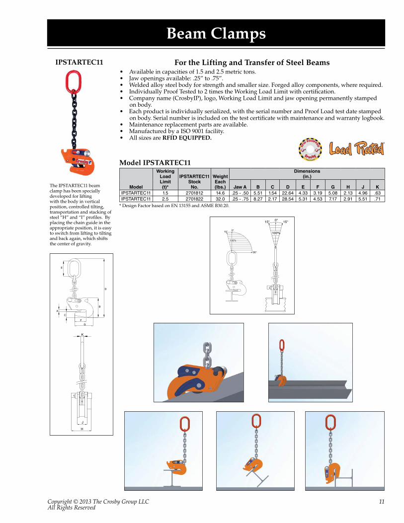
Beam Clamps
For the Lifting and Transfer of Steel Beams• Available in capacities of 1.5 and 2.5 metric tons.• Jaw openings available: .25” to .75”.• Welded alloy steel body for strength and smaller size. Forged alloy components, where required.• Individually Proof Tested to 2 times the Working Load Limit with certification. • Company name (CrosbyIP), logo, Working Load Limit and jaw opening permanently stamped
on body.• Each product is individually serialized, with the serial number and Proof Load test date stamped
on body. Serial number is included on the test certificate with maintenance and warranty logbook.• Maintenance replacement parts are available.• Manufactured by a ISO 9001 facility.• All sizes are RFID EQUIPPED.
The IPSTARTEC11 beam clamp has been specially developed for lifting with the body in vertical position, controlled tilting, transportation and stacking of steel “H” and “I” profiles. By placing the chain guide in the appropriate position, it is easy to switch from lifting to tilting and back again, which shifts the center of gravity.
Model
Working Load Limit(t)*
IPSTARTEC11StockNo.
WeightEach(lbs.)
Dimensions(in.)
Jaw A B C D E F G H J KIPSTARTEC11 1.5 2701812 14.6 .25 - .50 5.51 1.54 22.64 4.33 3.19 5.08 2.13 4.96 .63IPSTARTEC11 2.5 2701822 32.0 .25 - .75 8.27 2.17 28.54 5.31 4.53 7.17 2.91 5.51 .71
Model IPSTARTEC11
* Design Factor based on EN 13155 and ASME B30.20.
IPSTARTEC11
Copyright © 2013 The Crosby Group LLCAll Rights Reserved
12
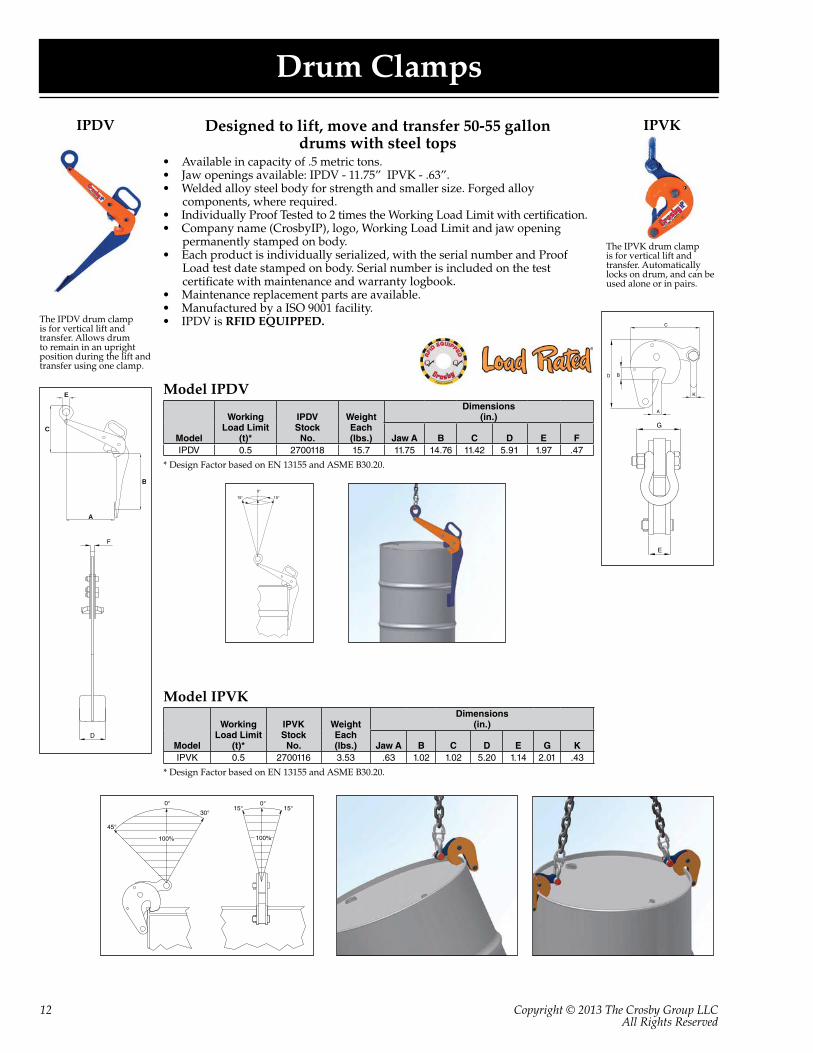
Drum Clamps
Designed to lift, move and transfer 50-55 gallon drums with steel tops
• Available in capacity of .5 metric tons.• Jaw openings available: IPDV - 11.75” IPVK - .63”.• Welded alloy steel body for strength and smaller size. Forged alloy
components, where required.• Individually Proof Tested to 2 times the Working Load Limit with certification. • Company name (CrosbyIP), logo, Working Load Limit and jaw opening
permanently stamped on body.• Each product is individually serialized, with the serial number and Proof
Load test date stamped on body. Serial number is included on the test certificate with maintenance and warranty logbook.
• Maintenance replacement parts are available.• Manufactured by a ISO 9001 facility.• IPDV is RFID EQUIPPED.The IPDV drum clamp
is for vertical lift and transfer. Allows drum to remain in an upright position during the lift and transfer using one clamp.
The IPVK drum clamp is for vertical lift and transfer. Automatically locks on drum, and can be used alone or in pairs.
E
C
B
A
IPDV IPVK
Model
Working Load Limit
(t)*
IPDVStockNo.
WeightEach(lbs.)
Dimensions(in.)
Jaw A B C D E FIPDV 0.5 2700118 15.7 11.75 14.76 11.42 5.91 1.97 .47
Model IPDV
* Design Factor based on EN 13155 and ASME B30.20.
Model
Working Load Limit
(t)*
IPVKStockNo.
WeightEach(lbs.)
Dimensions(in.)
Jaw A B C D E G KIPVK 0.5 2700116 3.53 .63 1.02 1.02 5.20 1.14 2.01 .43
Model IPVK
* Design Factor based on EN 13155 and ASME B30.20.

Copyright © 2013 The Crosby Group LLCAll Rights Reserved
13
Vertical Clamps
IPCCFor the Lifting and Transfer of
Concrete Pipe Sections and Wells
Model IPCC
• Available in capacity of 1 metric tons.• Jaw opening available: 1.56” - 5.50”.• Welded alloy steel body for strength and smaller size. Forged alloy components,
where required.• Individually Proof Tested to 2 times the Working Load Limit with certification. • Company name (CrosbyIP), logo, Working Load Limit and jaw opening
permanently stamped on body.• Each product is individually serialized, with the serial number and Proof Load
test date stamped on body. Serial number is included on the test certificate with maintenance and warranty logbook.
• Maintenance and replacement parts are available.• Manufactured by a ISO 9001 facility.• All sizes are RFID EQUIPPED.
ModelIPCC
Stock No.
WorkingLoad Limit
Per Pair (t.)*
Weight Each (lbs.)
Dimensions(in.)
JawA B C D E F G H J K
IPCC 2700037 1.0 20.3 1.56-5.50 8.86 3.15 5.75 - 14.65 1.46 - - -
* Design Factor based on EN 13155 and ASME B30.20.
AC
F
B
D
G
100%
0°15°15°
The IPCC is suitable for the vertical lift-ing and transfer of concrete pipe sections and wells. Very easy application and re-moval of the clamp thanks to the built-in carrying-grips. Normally used in combination with 7mm chain (not supplied). These clamps must be used in pairs or more.

Copyright © 2013 The Crosby Group LLCAll Rights Reserved
14
Shipbuilding Clamps: Bulb Profiles
For the lifting, transfer and placing of Bulb Profiles onto Ship’s Hulls Perpendicularly
• Available in capacities of .75 thru 3.75 metric tons.• Jaw openings available: HP 4.75” to HP 17.00”. • Welded alloy steel body for strength and smaller size. Forged alloy components, where required.• Individually Proof Tested to 2 times the Working Load Limit with certification. • Company name (CrosbyIP), logo, Working Load Limit and jaw opening permanently stamped
on body.• Each product is individually serialized, with the serial number and Proof Load test date
stamped on body. Serial number is included on the test certificate with maintenance and warranty logbook.
• Optional IP-5000 Stinger assembly available (see page 17). Allows for easy connection between the clamp and hoist hook.
• Maintenance replacement parts are available.• Manufactured by a ISO 9001 facility.• All sizes are RFID EQUIPPED.
The IPBUZ shipbuilding clamps are used for the lifting, transfer and placing of bulb profiles onto ship’s hulls perpendicularly. These clamps are fitted with a locking device for both open and closed positions, which ensures complete reliability. They are to be used exclusivly for bulb profiles (not for plates).
0° 15°15°
100%
IPBUZ
Model
WorkingLoad Limit(t)*
StockNo.
WeightEach(lbs.)
Dimensions(in.)
Jaw A B C D E F G H KIPBUUZ .75 2705601 18.7 HP 4.75-7.88 3.35 8.90 15.35 2.76 8.27 2.40 2.76 .63
With fixed hoisting eyeIPBUZ .75 2705600 15.4 HP 4.75-7.88 3.35 8.90 15.35 2.76 8.27 2.40 2.76 .63IPBUZ 1.5 2705701 33.1 HP 8.63-17.00 7.72 15.63 22.36 2.76 10.08 2.72 1.89 .63IPBUZ 3.75 2705702 62.9 HP 8.63-17.00 9.37 17.24 22.24 3.15 13.98 2.52 3.94 .79
Model IPBUUZ: with Universal Hoisting EyeModel IPBUZ: with Fixed Hoisting Eye
* Design Factor based on EN 13155 and ASME B30.20.

Copyright © 2013 The Crosby Group LLCAll Rights Reserved
15
Shipbuilding Clamps: Shipsections
For the lifting, transfer and placing of complete shipsections• Available in capacities of 4.5 thru 22.50 metric tons.• Wide variety of jaw openings available: HP 4.00” to HP 17.00”. • Welded alloy steel body for strength and smaller size. Forged alloy components, where required.• Individually Proof Tested to 2 times the Working Load Limit with certification. • Company name (CrosbyIP), logo, Working Load Limit and jaw opening permanently stamped
on body.• Each product is individually serialized, with the serial number and Proof Load test date stamped
on body. Serial number is included on the test certificate with maintenance and warranty logbook.
• Optional IP-5000 Stinger assembly available (see page 17). Allows for easy connection between the clamp and hoist hook.
• Maintenance replacement parts are available.• Manufactured by a ISO 9001 facility.• All sizes are RFID EQUIPPED.
The IPSBU(U)Z shipbuilding clamps are used for the lifting, transfer and placing of complete shipsections. These clamps are fitted with a locking device for both open and closed positions, which ensures complete reliability. They are to be used exclusively for bulb profiles (not for plates).
IPSBUUZ
Model
WorkingLoad Limit
(t)*StockNo.
WeightEach(lbs.)
Dimensions(in.)
Jaw A B C D E F G H J KIPSBUUZ 4.5 2705771 34.2 HP 4.00-6.25 4.21 9.92 17.72 2.95 8.11 3.78 3.23 1.42 .79
IPSBUSUZ 4.5 2705772 83.8 HP 7.13-17.00 8.94 16.85 25.00 2.95 14.84 3.74 5.04 - .79IPSBUUZ 9 2705773 94.8 HP 4.00-6.25 4.13 10.79 19.33 3.15 9.76 4.84 4.09 1.73 .79
IPSBUSUZ 9 2705774 130 HP 7.13-17.00 8.94 18.82 28.27 3.15 16.73 4.65 6.10 1.73 .98With fixed hoisting eye
IPSBUZ 4.5 2705721 29.8 HP 4.00-6.25 4.21 9.92 15.04 2.95 8.11 3.78 3.23 - .79IPSBUSZ 4.5 2705722 78.9 HP 7.13-17.00 8.94 16.85 23.31 2.95 14.84 3.74 5.04 - .79IPSBUZ 9 2705723 50.7 HP 4.00-6.25 4.13 10.79 18.15 3.15 9.76 4.84 4.09 - 1.18
IPSBUSZ 9 2705724 150 HP 7.13-17.00 8.94 18.82 26.46 3.15 16.73 4.65 6.10 1.77 .98IPSBUSZ 15 2705728 141 HP 7.13-17.00 8.90 19.09 27.17 3.46 15.79 3.94 5.31 1.93 .98IPSBUSZ 22.50 2705730 221 HP 7.13-17.00 8.82 21.38 29.13 3.54 18.50 4.57 7.28 - 1.18
Model IPSBUUZ and IPSBUSUZ: With Universal Hoisting EyeModel IPSBUZ and IPSBUSZ: With Fixed Hoisting Eye
* Design Factor based on EN 13155 and ASME B30.20.

Copyright © 2013 The Crosby Group LLCAll Rights Reserved
16
Shipbuilding Clamps: Bulbprofiles
For use as a temporary tackle eye in spaces which have been reinforced with HP (bulb) profiles such as engine rooms and shipsections.
• Available in capacities of 1.5 thru 6 metric tons.• Wide variety of jaw openings available: HP 6.25” to HP 17.00”. • Welded alloy steel body for strength and smaller size. Forged alloy components, where required.• Individually Proof Tested to 2 times the Working Load Limit with certification. • Company name (CrosbyIP), logo, Working Load Limit and jaw opening permanently stamped
on body.• Each product is individually serialized, with the serial number and Proof Load test date
stamped on body. Serial number is included on the test certificate with maintenance and warranty logbook.
• Maintenance replacement parts are available.• Manufactured by a ISO 9001 facility.
The IPBTO/10 shipbuilding clamp is used as a temporary tackle eye in spaces which have been reinforced with HP (bulb) profiles such as engine rooms and shipsections. This clamp is fitted with a screwed spindle for easy attachment of the clamp. The moment a load is applied, the clamp is automatically fixed.
IPBTO10
Model
WorkingLoad Limit(t)*
IPBTO10StockNo.
WeightEach(lbs.)
Dimensions(in.)
Jaw A B C D E FIPBTO10 1.5 2700980 9.48 HP 6.25-9.44 5.39 7.4-8.23 5.08-5.91 2.68 3.19IPBTO10 3 2700986 13.2 HP 9.44-12.56 5.39 7.4-8.54 5.71-6.85 2.68 3.07IPBTO10 6 2700991 28.7 HP 11.75-17.00 7.28 10.03-11.69 7.68-9.29 3.86 4.02
Model IPBTO10
* Design Factor based on EN 13155 and ASME B30.20.

Copyright © 2013 The Crosby Group LLCAll Rights Reserved
17
Crosby IP Clamps – Misc.
Suitable for use in positioning & turning of steel plates and sections.Not to be used as a lifting clamp.
• Available in capacities of 1.5 and 3 metric tons.• Jaw openings available: 0” to 2”.• Suitable for steel with a surface hardness up to 30 Rc. • Forged alloy steel body for strength and smaller size. Forged alloy components, where required.• Individually Proof Tested to 2 times the Working Load Limit with certification. • Company name (CrosbyIP), logo, Working Load Limit and jaw opening permanently stamped
on body.• Each product is individually serialized, with the serial number and Proof Load test date
stamped on body. Serial number is included on the test certificate with maintenance and warranty logbook.
• Maintenance replacement parts are available.• Manufactured by a ISO 9001 facility.The IPSC screw style clamp
is for positioning, pulling and turning of plate or fabrications.
Provides easy attachment of selected Crosby® IP clamp to hoist hook.
• Available in three sizes in the IP10 and IPU10 with capacities from .5 to 12 metric tons.• Assembly consists of welded alloy master link, Grade 80 chain and A-1337 Lok-A-Loy for
attachment to the clamp hoisting eye.• Individually Proof Tested to 2.5 times the Working Load Limit of Grade 80 chain
with certification.• Company name or logo and frame number permanently stamped on link.• Locking system provides for simple assembly - no special tools needed.• Finish - Red Paint.• Manufactured by a ISO 9001 facility.
The IP5000 Stinger Assembly is designed to be used as a connecting link between the clamp and the hoist hook.
IPSC
IP5000
Model
WorkingLoad Limit(t)*
IPSCStockNo.
WeightEach(lbs.)
Dimensions(in.)
Jaw A B C D E F G H J KIPSC 1.5 2701640 8.82 0 - 1.25 3.58 5.63 9.02 1.77 6.06 1.81 2.05 .63 2.05IPSC 3 2701641 13.2 0 - 2.00 4.13 6.50 10.43 1.97 7.48 2.13 2.32 .75 2.36
Model IPSC
* Design Factor based on EN 13155 and ASME B30.20.
FrameSize
Chain SizeCrosby®
IP10 and IPU10Clamp Sizes
(t)*
IP5000StockNo.
WeightEach(lbs.)
Dimensions(in.)
(in.) (mm) A B C D1 5/16 8 0.5 - 1 2701695 2.10 .51 2.36 3.94 12.412 1/2 13 2 - 4.5 2701704 7.50 .87 3.54 5.67 19.063 7/8 22 6 - 12 2701713 32.4 1.42 5.51 9.22 32.27
Model IP5000
* The working load of the assembly is based on working load limit of the selected clamp. Ultimate load is 5 times the Working Load Limit.
NOTE: Not intended to be used as a chain sling.

“A Strong Grip on Performance with Uncompromising Quality.”
Crosby Products Distributed By:
For more information, Contact:
USAP.O. Box 3128
Tulsa, OK 74101(918) 834-4611
Fax: (918)[email protected]
CANADA145 Heart Lake Road
Brampton, Ontario L6W 3K3(905) 451-9261
Fax: (877) [email protected]
EUROPEIndustriepark Zone B n°26
2220 Heist-op-den-bergBelgium
(+32) (0) 15 75 71 25Fax: (+32) (0) 15 75 37 [email protected]
9999495 PPG2.5M 3/13