crosby omni-trim direct spring pressure relief valves · 2019-09-05 · 3 crosby omni-trim® series...
TRANSCRIPT
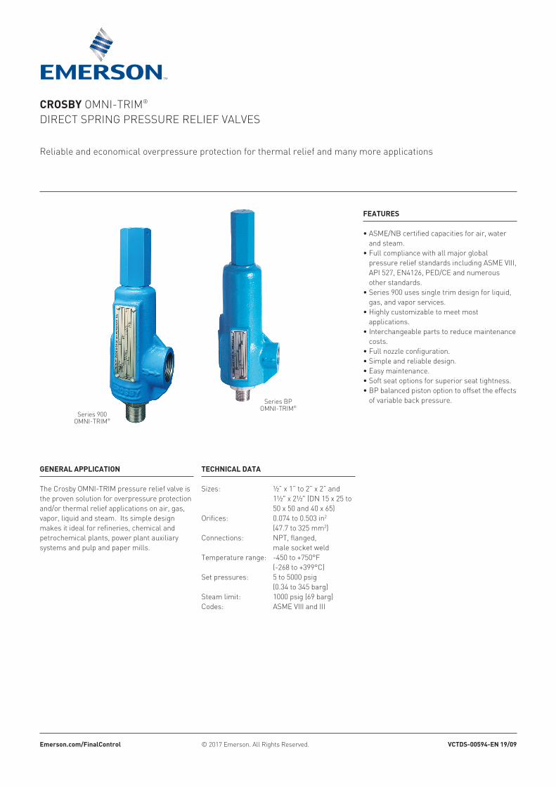
CROSBY OMNI-TRIM®
DIRECT SPRING PRESSURE RELIEF VALVES
Emerson.com/FinalControl
Reliable and economical overpressure protection for thermal relief and many more applications
FEATURES
• ASME/NB certified capacities for air, water and steam.
• Full compliance with all major global pressure relief standards including ASME VIII, API 527, EN4126, PED/CE and numerous other standards.
• Series 900 uses single trim design for liquid, gas, and vapor services.
• Highly customizable to meet most applications.
• Interchangeable parts to reduce maintenance costs.
• Full nozzle configuration.• Simple and reliable design.• Easy maintenance.• Soft seat options for superior seat tightness.• BP balanced piston option to offset the effects
of variable back pressure.
GENERAL APPLICATION
The Crosby OMNI-TRIM pressure relief valve is the proven solution for overpressure protection and/or thermal relief applications on air, gas, vapor, liquid and steam. Its simple design makes it ideal for refineries, chemical and petrochemical plants, power plant auxiliary systems and pulp and paper mills.
TECHNICAL DATA
Sizes: ½” x 1” to 2” x 2” and 1½" x 2½" (DN 15 x 25 to 50 x 50 and 40 x 65)
Orifices: 0.074 to 0.503 in2 (47.7 to 325 mm2)
Connections: NPT, flanged, male socket weld
Temperature range: -450 to +750°F (-268 to +399°C)
Set pressures: 5 to 5000 psig (0.34 to 345 barg)
Steam limit: 1000 psig (69 barg)Codes: ASME VIII and III
© 2017 Emerson. All Rights Reserved. VCTDS-00594-EN 19/09
Series 900 OMNI-TRIM®
Series BP OMNI-TRIM®
2
CROSBY OMNI-TRIM®
DIRECT SPRING PRESSURE RELIEF VALVES
MODELS OVERVIEW
CONTENTS
Product range information ...................................................................................................................3-8Caps and lifting levers ..............................................................................................................................9Series 900 valve configurations..............................................................................................................10
Dimensions/weights/pressure and temperature ratingsSeries 900 ..........................................................................................................................................15-22Series BP ...........................................................................................................................................23-24
CapacitiesSeries 900 ..........................................................................................................................................25-35Series BP ...........................................................................................................................................36-39Series BP back pressure flow correction factors .................................................................................40
Ordering informationSeries 900/BP ....................................................................................................................................41-42Parts ........................................................................................................................................................43Sizing and selection software ................................................................................................................44
Series 900 OMNI-TRIMSeries 900 OMNI-TRIM pressure relief valves provide overpressure protection on air, gas, vapor, liquid thermal relief and steam service. Maximum fixed blowdown is typically 20% or less. Standardization of components in the OMNI-TRIM provides easy assembly, durability, ease of maintenance and lower inventory costs. The design and wide array of options provide maximum versatility and premium performance.
Series BP OMNI-TRIM®
Series BP OMNI-TRIM® pressure relief valve is a piston, single trim designed valve for gas, vapor and liquid applications involving variable back pressure. Full nozzle design with O-ring seat as standard.
Sizes: ½” x 1" to 2" x 2" and 1½” x 2½” Orifices: 0.074 to 0.503 in2
(47.74 to 324.5 mm2) Connections: NPT, flanged, male socket weld Temperaturerange: -450 to +750°F (-268 to +399°C) Set pressures: 5 to 5000 psig
(0.34 to 344.83 barg) Steam limit: 1000 psig Code: ASME VIII and ASME III
(15 psig and above)
Sizes: ¾” x 1" and 1" x 1" Orifices: 0.074 and 0.110 in2
(47.74 and 71 mm2) Connections: NPT, flanged Temperaturerange: -20 to +400°F (-28 to +204°C)Set pressures: 50 to 1500 psig
(3.45 to 103.44 barg) Code: ASME VIII and ASME III
3
CROSBY OMNI-TRIM® SERIES 900 FIXED BLOWDOWN OMNI-TRIM PRESSURE RELIEF VALVE
PRODUCT OVERVIEW
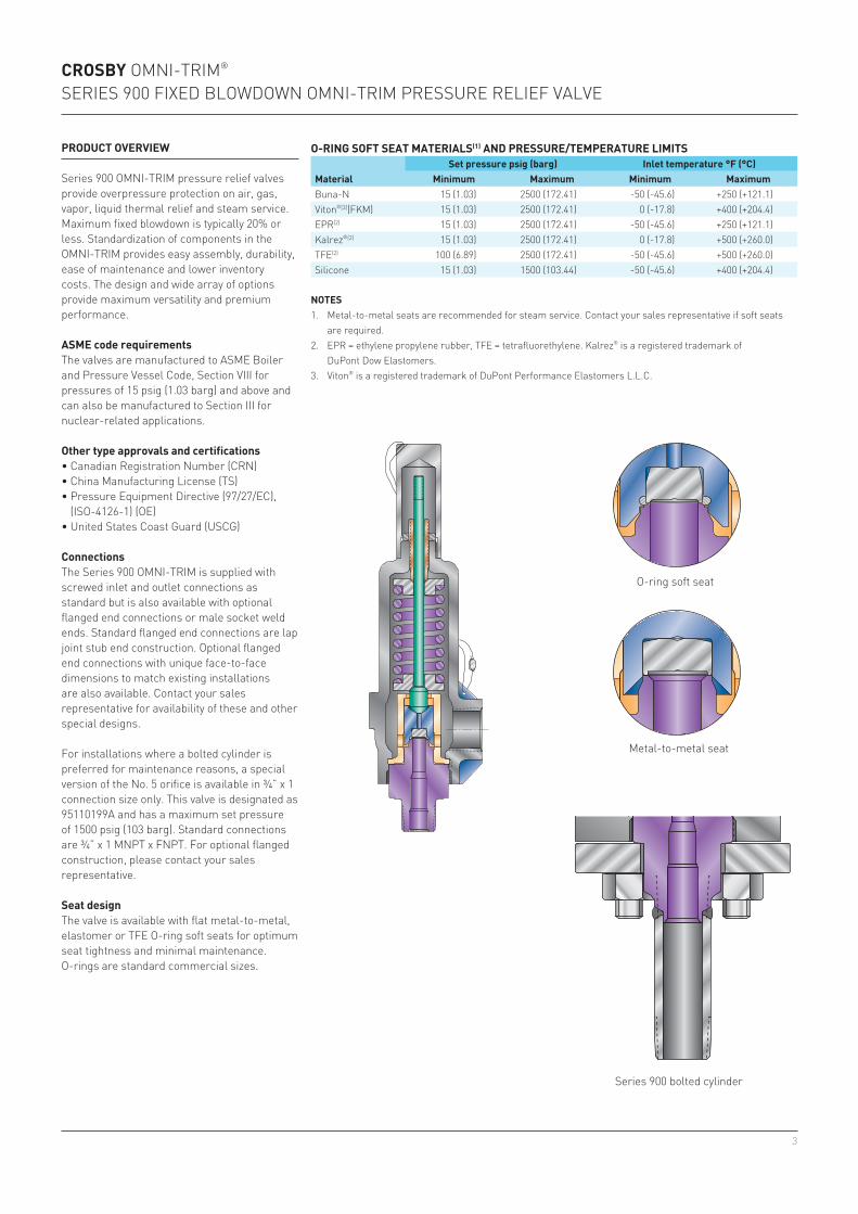
Series 900 OMNI-TRIM pressure relief valves provide overpressure protection on air, gas, vapor, liquid thermal relief and steam service. Maximum fixed blowdown is typically 20% or less. Standardization of components in the OMNI-TRIM provides easy assembly, durability, ease of maintenance and lower inventory costs. The design and wide array of options provide maximum versatility and premium performance.
ASME code requirementsThe valves are manufactured to ASME Boiler and Pressure Vessel Code, Section VIII for pressures of 15 psig (1.03 barg) and above and can also be manufactured to Section III for nuclear-related applications.
Other type approvals and certifications• Canadian Registration Number (CRN)• China Manufacturing License (TS)• Pressure Equipment Directive (97/27/EC),
(ISO-4126-1) (OE)• United States Coast Guard (USCG)
ConnectionsThe Series 900 OMNI-TRIM is supplied with screwed inlet and outlet connections as standard but is also available with optional flanged end connections or male socket weld ends. Standard flanged end connections are lap joint stub end construction. Optional flanged end connections with unique face-to-face dimensions to match existing installations are also available. Contact your sales representative for availability of these and other special designs.
For installations where a bolted cylinder is preferred for maintenance reasons, a special version of the No. 5 orifice is available in ¾” x 1 connection size only. This valve is designated as 95110199A and has a maximum set pressure of 1500 psig (103 barg). Standard connections are ¾” x 1 MNPT x FNPT. For optional flanged construction, please contact your sales representative.
Seat designThe valve is available with flat metal-to-metal, elastomer or TFE O-ring soft seats for optimum seat tightness and minimal maintenance. O-rings are standard commercial sizes.
O-RING SOFT SEAT MATERIALS(1) AND PRESSURE/TEMPERATURE LIMITSSet pressure psig (barg) Inlet temperature °F (°C)
Material Minimum Maximum Minimum MaximumBuna-N 15 (1.03) 2500 (172.41) -50 (-45.6) +250 (+121.1)Viton®[3](FKM) 15 (1.03) 2500 (172.41) 0 (-17.8) +400 (+204.4)EPR(2) 15 (1.03) 2500 (172.41) -50 (-45.6) +250 (+121.1)Kalrez®(2) 15 (1.03) 2500 (172.41) 0 (-17.8) +500 (+260.0)TFE(2) 100 (6.89) 2500 (172.41) -50 (-45.6) +500 (+260.0)Silicone 15 (1.03) 1500 (103.44) -50 (-45.6) +400 (+204.4)
NOTES1. Metal-to-metal seats are recommended for steam service. Contact your sales representative if soft seats
are required.2. EPR = ethylene propylene rubber, TFE = tetrafluorethylene. Kalrez® is a registered trademark of
DuPont Dow Elastomers.3. Viton® is a registered trademark of DuPont Performance Elastomers L.L.C.
O-ring soft seat
Metal-to-metal seat
Series 900 bolted cylinder
4
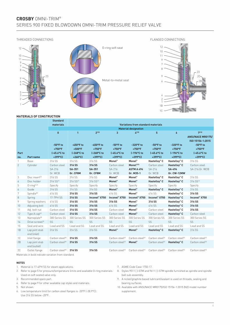
12
1011
978
964
532
1
23
12
1011
97
8
9
6
421
1B
1C
232C
2B
CROSBY OMNI-TRIM® SERIES 900 FIXED BLOWDOWN OMNI-TRIM PRESSURE RELIEF VALVE
Materials in bold indicate variation from standard.
NOTES1. Material is 17-4PH SS for steam applications.2. Refer to page 5 for pressure/temperature limits and available O-ring materials.
Used on soft seated valve only.3. Recommended spare part.4. Refer to page 9 for other available cap styles and materials.5. Not shown.6. Low temperature limit for carbon steel flanges is -20°F (-28.9°C).
Use 316 SS below -20°F.
MATERIALS OF CONSTRUCTION
Part no. Part name
Standard materials Variations from standard materials
Material designation0 1 2(10) 3 4(10) 5 6 7(10)
ANSI/NACE MR0175/ISO 15156-1:2015
-50°F to +750°F
-450°F to +500°F
-450°F to +750°F
-50°F to +750°F
-320°F to +750°F
-50°F to +750°F
-320°F to +750°F
-50°F to +750°F
(-45.6°C to +399°C)
(-268°C to +260°C)
(-268°C to +399°C)
(-45.6°C to +399°C)
(-196°C to +399°C)
(-45.6°C to +399°C)
(-196°C to +399°C)
(-45.6°C to +399°C)
1 Base 316 SS 316 SS 316 SS Monel® Monel® Hastelloy® C Hastelloy® C 316 SS2 Cylinder Carbon steel 316 SS 316 SS Carbon steel Monel®(7) Carbon steel Hastelloy® C Carbon steel
SA-216 Gr. WCB
SA-351 Gr. CF8M
SA-351 Gr. CF8M
SA-216 Gr. WCB
ASTM A 494 Gr. M35-1
SA-216 Gr. WCB
SA-494 Gr. CW-12MW
SA-216 Gr. WCB
3 Disc insert(3) 316 SS 316 SS 316 SS Monel® Monel® Hastelloy® C Hastelloy® C 316 SS4 Disc holder 316 SS(1) 316 SS(1) 316 SS(1) Monel® Monel® Hastelloy® C Hastelloy® C 316 SS(1)
5 O-ring(2,3) Specify Specify Specify Specify Specify Specify Specify Specify6 Guide 316 SS 316 SS 316 SS Monel® Monel® Hastelloy® C Hastelloy® C 316 SS7 Spindle(8) 416 SS 316 SS 316 SS 416 SS Monel® 416 SS Hastelloy® C 316 SS8 Spring 17-7PH SS 316 SS Inconel® X750 Inconel® X750 Inconel® X750 Inconel® X750 Hastelloy® C Inconel® X7509 Spring washers 416 SS 316 SS 316 SS 316 SS Monel® 316 SS Hastelloy® C 316 SS10 Adjusting bolt 416 SS 316 SS 316 SS 416 SS Monel® 416 SS Hastelloy® C 316 SS11 Adj. bolt nut Carbon steel 316 SS 316 SS Carbon steel Monel® Carbon steel Hastelloy® C 316 SS12 Type A cap(4) Carbon steel 316 SS 316 SS Carbon steel Monel® Carbon steel Hastelloy® C Carbon steel13 Nameplate(5) 300 Series SS 300 Series SS 300 Series SS 300 Series SS 300 Series SS 300 Series SS 300 Series SS 300 Series SS14 Drive screws(5) SS SS SS SS SS SS SS SS15 Seal and wire Lead and SS Lead and SS Lead and SS Lead and SS Lead and SS Lead and SS Lead and SS Lead and SS1B Lap joint stub
end (inlet)316 SS 316 SS 316 SS Monel® Monel® Hastelloy® C Hastelloy® C 316 SS
1C Inlet flange Carbon steel(6) 316 SS 316 SS Carbon steel(6) Carbon steel(6) Carbon steel(6) Carbon steel(6) Carbon steel(6)
2B Lap joint stub end (outlet)
Carbon steel(6) 316 SS 316 SS Carbon steel(6) Monel® Carbon steel(6) Hastelloy® C Carbon steel(6)
2C Outlet flange Carbon steel(6) 316 SS 316 SS Carbon steel(6) Carbon steel(6) Carbon steel(6) Carbon steel(6) Carbon steel(6)
Metal-to-metal seat
O-ring soft seat
THREADED CONNECTIONS FLANGED CONNECTIONS
7. ASME Code Case 1750-17.8. Styles 9511 ( )-STM and 9611 ( )-STM spindle furnished as spindle and spindle
ball sub-assembly.9. A nickel/graphite based lubricant/sealant is used on threads, sealing and
bearing surfaces.10. Available with ANSI/NACE MR0175/ISO 15156-1:2015 (N2) model number
supplement.
5
CROSBY OMNI-TRIM® SERIES BP BALANCED OMNI-TRIM PRESSURE RELIEF VALVE
PRODUCT OVERVIEW
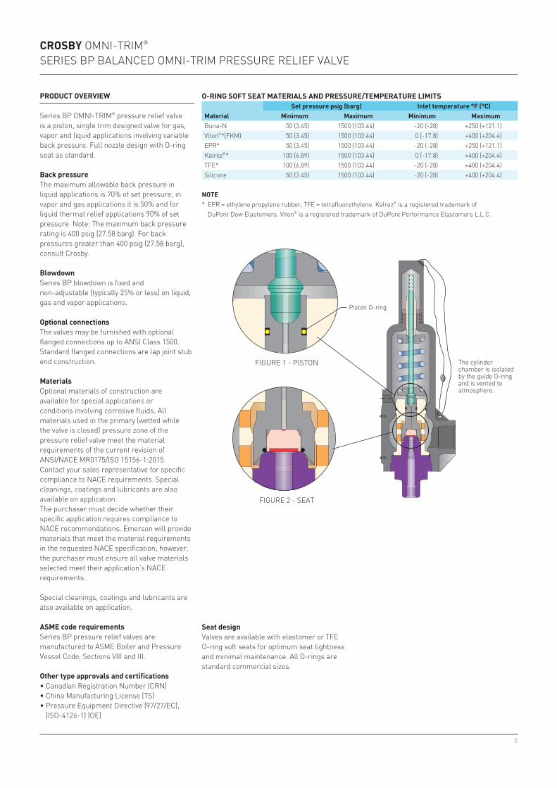
Series BP OMNI-TRIM® pressure relief valve is a piston, single trim designed valve for gas, vapor and liquid applications involving variable back pressure. Full nozzle design with O-ring seat as standard.
Back pressureThe maximum allowable back pressure in liquid applications is 70% of set pressure; in vapor and gas applications it is 50% and for liquid thermal relief applications 90% of set pressure. Note: The maximum back pressure rating is 400 psig (27.58 barg). For back pressures greater than 400 psig (27.58 barg), consult Crosby.
BlowdownSeries BP blowdown is fixed and non-adjustable (typically 25% or less) on liquid, gas and vapor applications.
Optional connectionsThe valves may be furnished with optional flanged connections up to ANSI Class 1500. Standard flanged connections are lap joint stub end construction.
MaterialsOptional materials of construction are available for special applications or conditions involving corrosive fluids. All materials used in the primary (wetted while the valve is closed) pressure zone of the pressure relief valve meet the material requirements of the current revision of ANSI/NACE MR0175/ISO 15156-1:2015. Contact your sales representative for specific compliance to NACE requirements. Special cleanings, coatings and lubricants are also available on application.The purchaser must decide whether their specific application requires compliance to NACE recommendations. Emerson will provide materials that meet the material requirements in the requested NACE specification; however, the purchaser must ensure all valve materials selected meet their application's NACE requirements.
Special cleanings, coatings and lubricants are also available on application.
ASME code requirementsSeries BP pressure relief valves are manufactured to ASME Boiler and Pressure Vessel Code, Sections VIII and III.
Other type approvals and certifications• Canadian Registration Number (CRN)• China Manufacturing License (TS)• Pressure Equipment Directive (97/27/EC),
(ISO-4126-1) (OE)
O-RING SOFT SEAT MATERIALS AND PRESSURE/TEMPERATURE LIMITSSet pressure psig (barg) Inlet temperature °F (°C)
Material Minimum Maximum Minimum MaximumBuna-N 50 (3.45) 1500 (103.44) -20 (-28) +250 (+121.1)Viton®*(FKM) 50 (3.45) 1500 (103.44) 0 (-17.8) +400 (+204.4)EPR* 50 (3.45) 1500 (103.44) -20 (-28) +250 (+121.1)Kalrez®* 100 (6.89) 1500 (103.44) 0 (-17.8) +400 (+204.4)TFE* 100 (6.89) 1500 (103.44) -20 (-28) +400 (+204.4)Silicone 50 (3.45) 1500 (103.44) -20 (-28) +400 (+204.4)
NOTE* EPR = ethylene propylene rubber, TFE = tetrafluorethylene. Kalrez® is a registered trademark of
DuPont Dow Elastomers. Viton® is a registered trademark of DuPont Performance Elastomers L.L.C.
FIGURE 1 - PISTON
FIGURE 2 - SEAT
Piston O-ring
The cylinder chamber is isolated by the guide O-ring and is vented to atmosphere.
Seat designValves are available with elastomer or TFE O-ring soft seats for optimum seat tightness and minimal maintenance. All O-rings are standard commercial sizes.
6
1210
11
9
8796
¼ NPT435
4039
21
1210
119
8796
¼ NPT435
40
39
21
3031
1537
38
15
3738
3332
CROSBY OMNI-TRIM® SERIES BP OMNI-TRIM PRESSURE RELIEF VALVE
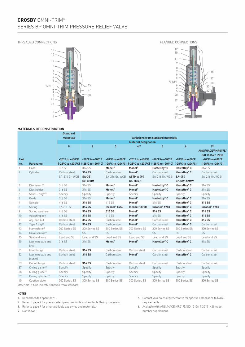
Materials in bold indicate variation from standard.
NOTES1. Recommended spare part.2. Refer to page 7 for pressure/temperature limits and available O-ring materials.3. Refer to page 9 for other available cap styles and materials.4. Not shown.
MATERIALS OF CONSTRUCTION
Part no. Part name
Standard materials Variations from standard materials
Material designation0 1 3 4(6) 5 6 7(6)
ANSI/NACE(5) MR0175/ISO 15156-1:2015
-20°F to +400°F -20°F to +400°F -20°F to +400°F -20°F to +400°F -20°F to +400°F -20°F to +400°F -20°F to +400°F (-28°C to +204°C) (-28°C to +204°C) (-28°C to +204°C) (-28°C to +204°C) (-28°C to +204°C) (-28°C to +204°C) (-28°C to +204°C)
1 Base 316 SS 316 SS Monel® Monel® Hastelloy® C Hastelloy® C 316 SS2 Cylinder Carbon steel 316 SS Carbon steel Monel® Carbon steel Hastelloy® C Carbon steel
SA-216 Gr. WCB SA-351 Gr. CF8M
SA-216 Gr. WCB ASTM A 494 Gr. M35-1
SA-216 Gr. WCB SA-494 Gr. CW-12MW
SA-216 Gr. WCB
3 Disc insert(1) 316 SS 316 SS Monel® Monel® Hastelloy® C Hastelloy® C 316 SS4 Disc holder 316 SS 316 SS Monel® Monel® Hastelloy® C Hastelloy® C 316 SS5 Seat O-ring(1,2) Specify Specify Specify Specify Specify Specify Specify6 Guide 316 SS 316 SS Monel® Monel® Hastelloy® C Hastelloy® C 316 SS7 Spindle 416 SS 316 SS 416 SS Monel® 416 SS Hastelloy® C 316 SS8 Spring 17-7PH SS 316 SS Inconel® X750 Inconel® X750 Inconel® X750 Hastelloy® C Inconel® X7509 Spring washers 416 SS 316 SS 316 SS Monel® 316 SS Hastelloy® C 316 SS10 Adjusting bolt 416 SS 316 SS 416 SS Monel® 416 SS Hastelloy® C 316 SS11 Adj. bolt nut Carbon steel 316 SS Carbon steel Monel® Carbon steel Hastelloy® C 316 SS12 Type A cap(3) Carbon steel 316 SS Carbon steel Monel® Carbon steel Hastelloy® C Carbon steel13 Nameplate(4) 300 Series SS 300 Series SS 300 Series SS 300 Series SS 300 Series SS 300 Series SS 300 Series SS14 Drive screws(4) SS SS SS SS SS SS SS15 Seal and wire Lead and SS Lead and SS Lead and SS Lead and SS Lead and SS Lead and SS Lead and SS30 Lap joint stub end
(inlet)316 SS 316 SS Monel® Monel® Hastelloy® C Hastelloy® C 316 SS
31 Inlet flange Carbon steel 316 SS Carbon steel Carbon steel Carbon steel Carbon steel Carbon steel32 Lap joint stub end
(outlet)Carbon steel 316 SS Carbon steel Monel® Carbon steel Hastelloy® C Carbon steel
33 Outlet flange Carbon steel 316 SS Carbon steel Carbon steel Carbon steel Carbon steel Carbon steel37 O-ring piston(1) Specify Specify Specify Specify Specify Specify Specify38 O-ring guide(1) Specify Specify Specify Specify Specify Specify Specify39 O-ring cylinder(1) Specify Specify Specify Specify Specify Specify Specify40 Caution plate 300 Series SS 300 Series SS 300 Series SS 300 Series SS 300 Series SS 300 Series SS 300 Series SS
THREADED CONNECTIONS FLANGED CONNECTIONS
5. Contact your sales representative for specific compliance to NACE requirements.
6. Available with ANSI/NACE MR0175/ISO 15156-1:2015 (N2) model number supplement.
7
12
27
28
16
26
25
19
1824
20
23
222129
27
26
25
19
1824
20
23
282221
CROSBY OMNI-TRIM® CAPS AND LIFTING LEVERS
MATERIALS OF CONSTRUCTION
Cap type Part no. Part nameMaterial designation
0, 3, 5 1, 2 4 6A 12 Cap Steel 316 SS Monel® Hastelloy® CB 16 Cap Steel 316 SS Monel® Hastelloy® C
27 Cap plug Steel 316 SS Monel® Hastelloy® C28 Cap plug O-ring FKM FKM FKM FKM29 Test rod Steel (plated) Steel (plated) Steel (plated) Steel (plated)
D 18 Cap Steel 316 SS Monel® Hastelloy® C19 Cam 416 SS 316 SS Monel® Hastelloy® C20 Cam O-ring FKM FKM FKM FKM21 Cam sleeve 416 SS 316 SS Monel® Hastelloy® C22 Cam sleeve O-ring FKM FKM FKM FKM23 Lever Steel Steel Steel Steel24 Lever pin 302 SS 302 SS 302 SS 302 SS25 Spindle nut Steel 316 SS Monel® Hastelloy® C26 Locknut Steel (plated) 300 Series SS Monel® Hastelloy® C
E 18 Cap Steel 316 SS Monel® Hastelloy® C19 Cam 416 SS 316 SS Monel® Hastelloy® C20 Cam O-ring FKM FKM FKM FKM21 Cam sleeve 416 SS 316 SS Monel® Hastelloy® C22 Cam sleeve O-ring FKM FKM FKM FKM23 Lever Steel Steel Steel Steel24 Lever pin 302 SS 302 SS 302 SS 302 SS25 Spindle nut Steel 316 SS Monel® Hastelloy® C26 Locknut Steel (plated) 300 Series SS Monel® Hastelloy® C27 Cap plug Steel 316 SS Monel® Hastelloy® C28 Cap plug O-ring FKM FKM FKM FKM29 Test rod Steel (plated) Steel (plated) Steel (plated) Steel (plated)
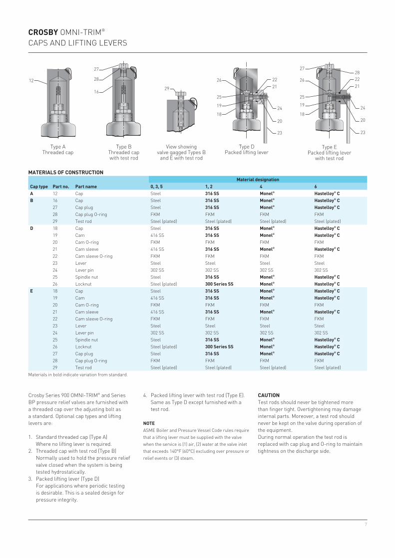
Crosby Series 900 OMNI-TRIM® and Series BP pressure relief valves are furnished with a threaded cap over the adjusting bolt as a standard. Optional cap types and lifting levers are:
1. Standard threaded cap (Type A) Where no lifting lever is required.2. Threaded cap with test rod (Type B) Normally used to hold the pressure relief
valve closed when the system is being tested hydrostatically.
3. Packed lifting lever (Type D) For applications where periodic testing
is desirable. This is a sealed design for pressure integrity.
Materials in bold indicate variation from standard.
Type AThreaded cap
Type BThreaded cap with test rod
View showing valve gagged Types B
and E with test rod
Type DPacked lifting lever
Type EPacked lifting lever
with test rod
4. Packed lifting lever with test rod (Type E). Same as Type D except furnished with a test rod.
NOTEASME Boiler and Pressure Vessel Code rules require that a lifting lever must be supplied with the valve when the service is (1) air, (2) water at the valve inlet that exceeds 140°F (60°C) excluding over pressure or relief events or (3) steam.
CAUTIONTest rods should never be tightened more than finger tight. Overtightening may damage internal parts. Moreover, a test rod should never be kept on the valve during operation of the equipment.During normal operation the test rod is replaced with cap plug and O-ring to maintain tightness on the discharge side.
8
CROSBY OMNI-TRIM® SERIES 900 VALVE CONFIGURATIONS
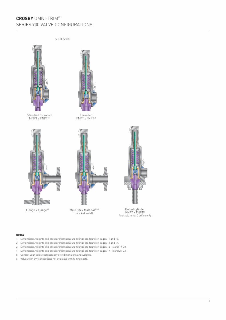
SERIES 900
Standard threadedMNPT x FNPT(3)
ThreadedFNPT x FNPT(3)
Flange x Flange(4) Male SW x Male SW(5,6)
(socket weld)Bolted cylinderMNPT x FNPT(3)
Available in no. 5 orifice only
NOTES1. Dimensions, weights and pressure/temperature ratings are found on pages 11 and 13.2. Dimensions, weights and pressure/temperature ratings are found on pages 12 and 14.3. Dimensions, weights and pressure/temperature ratings are found on pages 15-16 and 19-20.4. Dimensions, weights and pressure/temperature ratings are found on pages 17-18 and 21-22.5. Contact your sales representative for dimensions and weights.6. Valves with SW connections not available with O-ring seats.
9
A(±1/8”)
B(±1/8”)
B(±1/8”)
A(±1/8”)
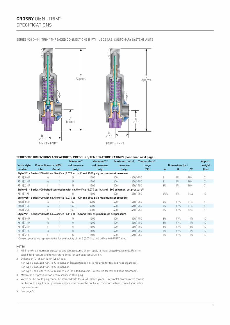
MNPT x FNPT FNPT x FNPT
9511( )0MF ½ 1 5 1500 400 -450/+750 3 1¾ 10⅜ 79511( )1MF ¾ 1 5 1500 400 -450/+750 3 1¾ 10⅜ 79511( )2MF 1 1 5 1500 400 -450/+750 3¼ 1¾ 10⅝ 7
9511( )199 ¾ 1 5 1500 400 -450/+750 6 13/16 1¾ 14¼ 12
9551( )0MF ½ 1 1501 5000 400 -450/+750 3⅛ 1 15/16 11⅞ 99551( )1MF ¾ 1 1501 5000 400 -450/+750 3⅛ 1 15/16 11⅞ 99551( )2MF 1 1 1501 5000 400 -450/+750 3⅜ 1 15/16 12⅛ 9
9611( )0MF ½ 1 5 1500 400 -450/+750 3⅛ 1 15/16 11⅞ 109611( )1MF ¾ 1 5 1500 400 -450/+750 3⅛ 1 15/16 11⅞ 109611( )2MF 1 1 5 1500 400 -450/+750 3⅜ 1 15/16 12⅛ 109611( )1FF ¾ 1 5 1500 400 -450/+750 2½ 1 15/16 11¼ 109611( )2FF 1 1 5 1500 400 -450/+750 2⅞ 1 15/16 11⅝ 10
SERIES 900 DIMENSIONS AND WEIGHTS, PRESSURE/TEMPERATURE RATINGS (continued next page)
Valve style number
Connection size (NPS)Minimum(4)
set pressureMaximum(1,3) set pressure
Maximum outlet pressure
Temperature(1) range Dimensions (in.)
Approx.weight
Inlet Outlet (psig) (psig) (psig) (°F) A B C(2) (lbs)Style 951 - Series 900 with no. 5 orifice (0.074 sq. in.)* and 1500 psig maximum set pressure
Style 951 - Series 900 bolted connection with no. 5 orifice (0.074 sq. in.) and 1500 psig max. set pressure(5)
Style 955 - Series 900 with no. 5 orifice (0.074 sq. in.)* and 5000 psig maximum set pressure
Style 961 - Series 900 with no. 6 orifice (0.110 sq. in.) and 1500 psig maximum set pressure
CROSBY OMNI-TRIM® SPECIFICATIONS
SERIES 900 OMNI-TRIM® THREADED CONNECTIONS (NPT) - USCS (U.S. CUSTOMARY SYSTEM) UNITS
CApprox. C
Approx.
* Consult your sales representative for availability of no. 5 (0.074 sq. in.) orifice with FNPT inlet.
NOTES1. Minimum/maximum set pressures and temperatures shown apply to metal seated valves only. Refer to
page 5 for pressure and temperature limits for soft seat construction.2. Dimension 'C' shown is for Type A cap. For Type B cap, add ¼ in. to 'C' dimension (an additional 2 in. is required for test rod head clearance). For Type D cap, add ⅝ in. to 'C' dimension. For Type E cap, add ⅞ in. to 'C' dimension (an additional 2 in. is required for test rod head clearance).3. Maximum set pressure for steam service is 1000 psig.4. Valves set below 15 psig cannot be stamped with the ASME Code Symbol. Only metal seated valves may be
set below 15 psig. For set pressure applications below the published minimum values, consult your sales representative.
5. See page 5.
10
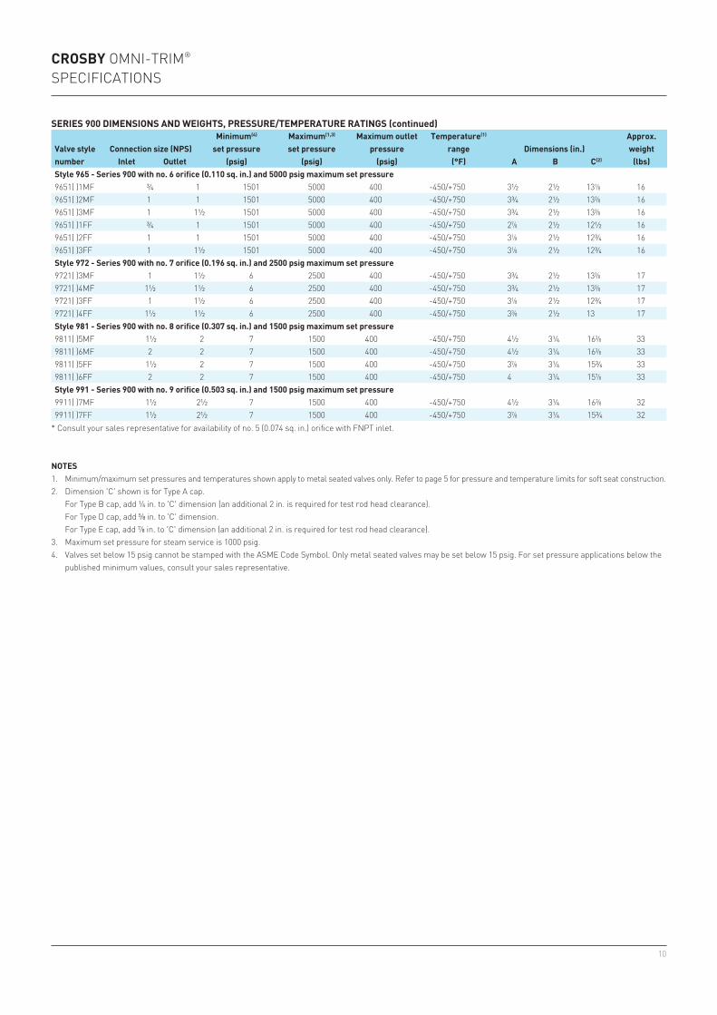
9721( )3MF 1 1½ 6 2500 400 -450/+750 3¾ 2½ 13⅜ 179721( )4MF 1½ 1½ 6 2500 400 -450/+750 3¾ 2½ 13⅜ 179721( )3FF 1 1½ 6 2500 400 -450/+750 3⅛ 2½ 12¾ 179721( )4FF 1½ 1½ 6 2500 400 -450/+750 3⅜ 2½ 13 17
9811( )5MF 1½ 2 7 1500 400 -450/+750 4½ 3¼ 16⅜ 339811( )6MF 2 2 7 1500 400 -450/+750 4½ 3¼ 16⅜ 339811( )5FF 1½ 2 7 1500 400 -450/+750 3⅞ 3¼ 15¾ 339811( )6FF 2 2 7 1500 400 -450/+750 4 3¼ 15⅞ 33
9911( )7MF 1½ 2½ 7 1500 400 -450/+750 4½ 3¼ 16⅜ 329911( )7FF 1½ 2½ 7 1500 400 -450/+750 3⅞ 3¼ 15¾ 32
9651( )1MF ¾ 1 1501 5000 400 -450/+750 3½ 2½ 13⅛ 169651( )2MF 1 1 1501 5000 400 -450/+750 3¾ 2½ 13⅜ 169651( )3MF 1 1½ 1501 5000 400 -450/+750 3¾ 2½ 13⅜ 169651( )1FF ¾ 1 1501 5000 400 -450/+750 2⅞ 2½ 12½ 169651( )2FF 1 1 1501 5000 400 -450/+750 3⅛ 2½ 12¾ 169651( )3FF 1 1½ 1501 5000 400 -450/+750 3⅛ 2½ 12¾ 16
CROSBY OMNI-TRIM® SPECIFICATIONS
* Consult your sales representative for availability of no. 5 (0.074 sq. in.) orifice with FNPT inlet.
NOTES1. Minimum/maximum set pressures and temperatures shown apply to metal seated valves only. Refer to page 5 for pressure and temperature limits for soft seat construction.2. Dimension 'C' shown is for Type A cap. For Type B cap, add ¼ in. to 'C' dimension (an additional 2 in. is required for test rod head clearance). For Type D cap, add ⅝ in. to 'C' dimension. For Type E cap, add ⅞ in. to 'C' dimension (an additional 2 in. is required for test rod head clearance).3. Maximum set pressure for steam service is 1000 psig.4. Valves set below 15 psig cannot be stamped with the ASME Code Symbol. Only metal seated valves may be set below 15 psig. For set pressure applications below the
published minimum values, consult your sales representative.
Style 981 - Series 900 with no. 8 orifice (0.307 sq. in.) and 1500 psig maximum set pressure
Style 972 - Series 900 with no. 7 orifice (0.196 sq. in.) and 2500 psig maximum set pressure
Style 991 - Series 900 with no. 9 orifice (0.503 sq. in.) and 1500 psig maximum set pressure
SERIES 900 DIMENSIONS AND WEIGHTS, PRESSURE/TEMPERATURE RATINGS (continued)
Valve style number
Connection size (NPS)Minimum(4)
set pressureMaximum(1,3) set pressure
Maximum outlet pressure
Temperature(1) range Dimensions (in.)
Approx.weight
Inlet Outlet (psig) (psig) (psig) (°F) A B C(2) (lbs)Style 965 - Series 900 with no. 6 orifice (0.110 sq. in.) and 5000 psig maximum set pressure
11
B(±⅛”)
A(±⅛”)
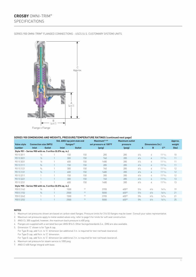
9511( )011 ½ 1 150 150 285 285 4¼ 4 11 11/16 109511( )021 ½ 1 300 150 740 285 4¼ 4 11 11/16 119511( )031 ½ 1 600 150 1480 285 4¼ 4 11 11/16 119511( )111 ¾ 1 150 150 285 285 4¼ 4 11 11/16 119511( )121 ¾ 1 300 150 740 285 4¼ 4 11 11/16 129511( )131 ¾ 1 600 150 1480 285 4¼ 4 11 11/16 129511( )211 1 1 150 150 285 285 4½ 4 11 15/16 129511( )221 1 1 300 150 740 285 4½ 4 11 15/16 139511( )231 1 1 600 150 1480 285 4½ 4 11 15/16 13
9551( )142 ¾ 1 1500 (3) 3705 400(3) 5½ 4½ 14 5/16 199551( )152 ¾ 1 2500 (3) 5000 400(3) 5½ 4½ 14 5/16 219551( )242 1 1 1500 (3) 3705 400(3) 5¾ 4½ 14 9/16 219551( )252 1 1 2500 (3) 5000 400(3) 5¾ 4½ 14 9/16 25
CROSBY OMNI-TRIM® SPECIFICATIONS
SERIES 900 OMNI-TRIM® FLANGED CONNECTIONS - USCS (U.S. CUSTOMARY SYSTEM) UNITS
Flange x Flange
CApprox.
SERIES 900 DIMENSIONS AND WEIGHTS, PRESSURE/TEMPERATURE RATINGS (continued next page)
Valve style number
Connection size (NPS)Std. ANSI lap joint stub end
flanges(4)
Maximum(1,2,6)
set pressure at 100°FMaximum outlet
pressure Dimensions (in.)Approx.weight
Inlet Outlet Inlet Outlet (psig) (psig) A B C(5) (lbs)Style 951 - Series 900 with no. 5 orifice (0.074 sq. in.)
Style 955 - Series 900 with no. 5 orifice (0.074 sq. in.)
NOTES1. Maximum set pressures shown are based on carbon steel flanges. Pressure limits for 316 SS flanges may be lower. Consult your sales representative.2. Maximum set pressures apply to metal seated valves only; refer to page 5 for limits for soft seat construction.3. ANSI CL 300 supplied; however, the maximum back pressure is 400 psig.4. Flanges are supplied with a serrated face per ANSI B16.5. Other facings/standards (i.e., DIN) are also available.5. Dimension 'C' shown is for Type A cap. For Type B cap, add ¼ in. to 'C' dimension (an additional 2 in. is required for test rod head clearance). For Type D cap, add ⅝ in. to 'C' dimension. For Type E cap, add ⅞ in. to 'C' dimension (an additional 2 in. is required for test rod head clearance).6. Maximum set pressure for steam service is 1000 psig.7. ANSI CI 600 flange integral with base.
12
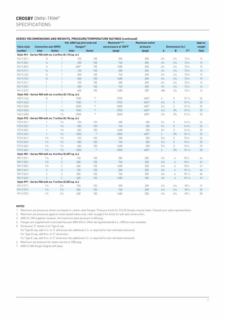
9651( )142 ¾ 1 1500 (3) 3705 400(3) 6 5 15 11/16 269651( )242 1 1 1500 (3) 3705 400(3) 6¼ 5 15 15/16 299651( )252 1 1 2500 (3) 5000 400(3) 6¼ 5 15 15/16 329651( )342 1 1½ 1500 (3) 3705 400(3) 6¼ 5¾ 15 15/16 299651( )352 1 1½ 2500 (3) 5000 400(3) 6¼ 5¾ 15 15/16 35
9721( )311 1 1½ 150 150 285 285 5⅛ 5 14 13/16 249721( )321 1 1½ 300 150 740 285 5⅛ 5 14 13/16 259721( )331 1 1½ 600 150 1480 285 5⅛ 5 14 13/16 259721( )341 1 1½ 1500 (3) 2500 400(3) 6 5¾ 15 11/16 329721( )411 1½ 1½ 150 150 285 285 5½ 5 15 3/16 269721( )421 1½ 1½ 300 150 740 285 5½ 5 15 3/16 299721( )431 1½ 1½ 600 150 1480 285 5½ 5 15 3/16 299721( )441 1½ 1½ 1500 (3) 2500 400(3) 6 5¾ 15 11/16 38
9811( )511 1½ 2 150 150 285 285 6½ 6 18 7/16 449811( )521 1½ 2 300 150 740 285 6½ 6 18 7/16 479811( )531 1½ 2 600 150 1480 285 6½ 6 18 7/16 479811( )611 2 2 150 150 285 285 6¾ 6 18 11/16 469811( )621 2 2 300 150 740 285 6¾ 6 18 11/16 489811( )631 2 2 600 150 1480 285 6¾ 6 18 11/16 49
9911( )711 1½ 2½ 150 150 285 285 6½ 6½ 18 7/16 479911( )721 1½ 2½ 300 150 740 285 6½ 6½ 18 7/16 509911( )731 1½ 2½ 600 150 1480 285 6½ 6½ 18 7/16 50
9611( )011 ½ 1 150 150 285 285 4⅜ 4¼ 13 3/16 149611( )021 ½ 1 300 150 740 285 4⅜ 4¼ 13 3/16 159611( )031 ½ 1 600(7) 150 1480 285 4⅜ 4¼ 13 3/16 159611( )111 ¾ 1 150 150 285 285 4⅜ 4¼ 13 3/16 149611( )121 ¾ 1 300 150 740 285 4⅜ 4¼ 13 3/16 159611( )131 ¾ 1 600 150 1480 285 4⅜ 4¼ 13 3/16 159611( )211 1 1 150 150 285 285 4⅝ 4¼ 13 7/16 149611( )221 1 1 300 150 740 285 4⅝ 4¼ 13 7/16 169611( )231 1 1 600 150 1480 285 4⅝ 4¼ 13 7/16 16
CROSBY OMNI-TRIM® SPECIFICATIONS
NOTES1. Maximum set pressures shown are based on carbon steel flanges. Pressure limits for 316 SS flanges may be lower. Consult your sales representative.2. Maximum set pressures apply to metal seated valves only; refer to page 5 for limits for soft seat construction.3. ANSI CL 300 supplied; however, the maximum back pressure is 400 psig.4. Flanges are supplied with a serrated face per ANSI B16.5. Other facings/standards (i.e., DIN) are also available.5. Dimension 'C' shown is for Type A cap. For Type B cap, add ¼ in. to 'C' dimension (an additional 2 in. is required for test rod head clearance). For Type D cap, add ⅝ in. to 'C' dimension. For Type E cap, add ⅞ in. to 'C' dimension (an additional 2 in. is required for test rod head clearance).6. Maximum set pressure for steam service is 1000 psig.7. ANSI CI 600 flange integral with base.
Style 972 - Series 900 with no. 7 orifice (0.196 sq. in.)
Style 981 - Series 900 with no. 8 orifice (0.307 sq. in.)
Style 991 - Series 900 with no. 9 orifice (0.503 sq. in.)
SERIES 900 DIMENSIONS AND WEIGHTS, PRESSURE/TEMPERATURE RATINGS (continued)
Valve style number
Connection size (NPS)Std. ANSI lap joint stub end
flanges(4)
Maximum(1,2,6)
set pressure at 100°FMaximum outlet
pressure Dimensions (in.)Approx.weight
Inlet Outlet Inlet Outlet (psig) (psig) A B C(5) (lbs)Style 961 - Series 900 with no. 6 orifice (0.110 sq. in.)
Style 965 - Series 900 with no. 6 orifice (0.110 sq. in.)
13
MNPT x FNPT FNPT x FNPT
A(±3 mm)
B(±3 mm)
A(±3 mm)
B(±3 mm)
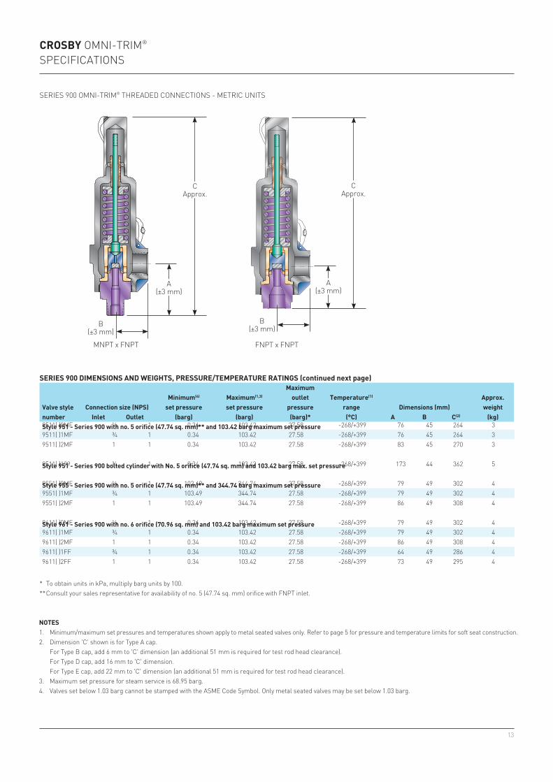
9511( )0MF ½ 1 0.34 103.42 27.58 -268/+399 76 45 264 39511( )1MF ¾ 1 0.34 103.42 27.58 -268/+399 76 45 264 39511( )2MF 1 1 0.34 103.42 27.58 -268/+399 83 45 270 3
9511( )199 ¾ 1 0.34 103.42 27.58 -268/+399 173 44 362 5
9551( )0MF ½ 1 103.49 344.74 27.58 -268/+399 79 49 302 49551( )1MF ¾ 1 103.49 344.74 27.58 -268/+399 79 49 302 49551( )2MF 1 1 103.49 344.74 27.58 -268/+399 86 49 308 4
9611( )0MF ½ 1 0.34 103.42 27.58 -268/+399 79 49 302 49611( )1MF ¾ 1 0.34 103.42 27.58 -268/+399 79 49 302 49611( )2MF 1 1 0.34 103.42 27.58 -268/+399 86 49 308 49611( )1FF ¾ 1 0.34 103.42 27.58 -268/+399 64 49 286 49611( )2FF 1 1 0.34 103.42 27.58 -268/+399 73 49 295 4
CROSBY OMNI-TRIM® SPECIFICATIONS
SERIES 900 OMNI-TRIM® THREADED CONNECTIONS - METRIC UNITS
SERIES 900 DIMENSIONS AND WEIGHTS, PRESSURE/TEMPERATURE RATINGS (continued next page)
Valve style number
Connection size (NPS)Minimum(4)
set pressureMaximum(1,3) set pressure
Maximum outlet
pressureTemperature(1)
range Dimensions (mm)Approx.weight
Inlet Outlet (barg) (barg) (barg)* (°C) A B C(2) (kg)Style 951 - Series 900 with no. 5 orifice (47.74 sq. mm)** and 103.42 barg maximum set pressure
Style 951 - Series 900 bolted cylinder with No. 5 orifice (47.74 sq. mm) and 103.42 barg max. set pressure
Style 955 - Series 900 with no. 5 orifice (47.74 sq. mm)** and 344.74 barg maximum set pressure
Style 961 - Series 900 with no. 6 orifice (70.96 sq. mm) and 103.42 barg maximum set pressure
CApprox.
CApprox.
NOTES1. Minimum/maximum set pressures and temperatures shown apply to metal seated valves only. Refer to page 5 for pressure and temperature limits for soft seat construction.2. Dimension 'C' shown is for Type A cap. For Type B cap, add 6 mm to 'C' dimension (an additional 51 mm is required for test rod head clearance). For Type D cap, add 16 mm to 'C' dimension. For Type E cap, add 22 mm to 'C' dimension (an additional 51 mm is required for test rod head clearance).3. Maximum set pressure for steam service is 68.95 barg.4. Valves set below 1.03 barg cannot be stamped with the ASME Code Symbol. Only metal seated valves may be set below 1.03 barg.
* To obtain units in kPa, multiply barg units by 100.** Consult your sales representative for availability of no. 5 (47.74 sq. mm) orifice with FNPT inlet.
14
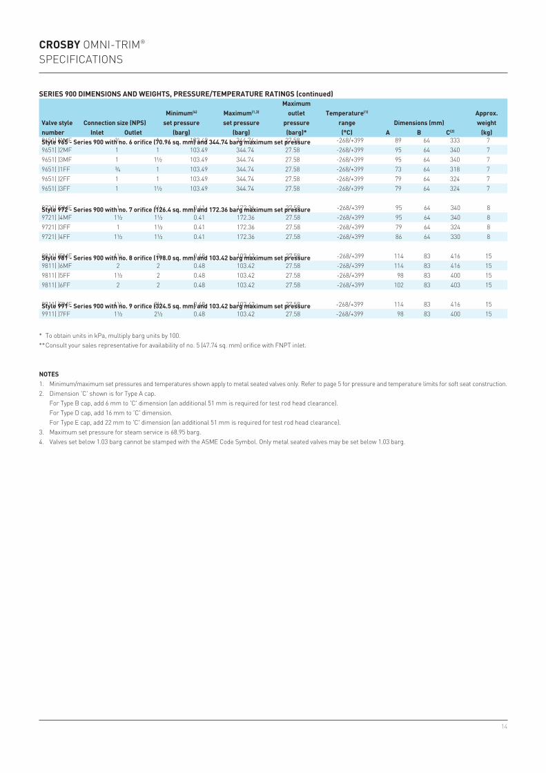
9721( )3MF 1 1½ 0.41 172.36 27.58 -268/+399 95 64 340 89721( )4MF 1½ 1½ 0.41 172.36 27.58 -268/+399 95 64 340 89721( )3FF 1 1½ 0.41 172.36 27.58 -268/+399 79 64 324 89721( )4FF 1½ 1½ 0.41 172.36 27.58 -268/+399 86 64 330 8
9811( )5MF 1½ 2 0.48 103.42 27.58 -268/+399 114 83 416 159811( )6MF 2 2 0.48 103.42 27.58 -268/+399 114 83 416 159811( )5FF 1½ 2 0.48 103.42 27.58 -268/+399 98 83 400 159811( )6FF 2 2 0.48 103.42 27.58 -268/+399 102 83 403 15
9911( )7MF 1½ 2½ 0.48 103.42 27.58 -268/+399 114 83 416 159911( )7FF 1½ 2½ 0.48 103.42 27.58 -268/+399 98 83 400 15
9651( )1MF ¾ 1 103.49 344.74 27.58 -268/+399 89 64 333 79651( )2MF 1 1 103.49 344.74 27.58 -268/+399 95 64 340 79651( )3MF 1 1½ 103.49 344.74 27.58 -268/+399 95 64 340 79651( )1FF ¾ 1 103.49 344.74 27.58 -268/+399 73 64 318 79651( )2FF 1 1 103.49 344.74 27.58 -268/+399 79 64 324 79651( )3FF 1 1½ 103.49 344.74 27.58 -268/+399 79 64 324 7
CROSBY OMNI-TRIM® SPECIFICATIONS
* To obtain units in kPa, multiply barg units by 100.** Consult your sales representative for availability of no. 5 (47.74 sq. mm) orifice with FNPT inlet.
NOTES1. Minimum/maximum set pressures and temperatures shown apply to metal seated valves only. Refer to page 5 for pressure and temperature limits for soft seat construction.2. Dimension 'C' shown is for Type A cap. For Type B cap, add 6 mm to 'C' dimension (an additional 51 mm is required for test rod head clearance). For Type D cap, add 16 mm to 'C' dimension. For Type E cap, add 22 mm to 'C' dimension (an additional 51 mm is required for test rod head clearance).3. Maximum set pressure for steam service is 68.95 barg.4. Valves set below 1.03 barg cannot be stamped with the ASME Code Symbol. Only metal seated valves may be set below 1.03 barg.
Style 981 - Series 900 with no. 8 orifice (198.0 sq. mm) and 103.42 barg maximum set pressure
Style 991 - Series 900 with no. 9 orifice (324.5 sq. mm) and 103.42 barg maximum set pressure
SERIES 900 DIMENSIONS AND WEIGHTS, PRESSURE/TEMPERATURE RATINGS (continued)
Valve style number
Connection size (NPS)Minimum(4)
set pressureMaximum(1,3) set pressure
Maximum outlet
pressureTemperature(1)
range Dimensions (mm)Approx.weight
Inlet Outlet (barg) (barg) (barg)* (°C) A B C(2) (kg)Style 965 - Series 900 with no. 6 orifice (70.96 sq. mm) and 344.74 barg maximum set pressure
Style 972 - Series 900 with no. 7 orifice (126.4 sq. mm) and 172.36 barg maximum set pressure
15
A(±3 mm)
B(±3 mm)
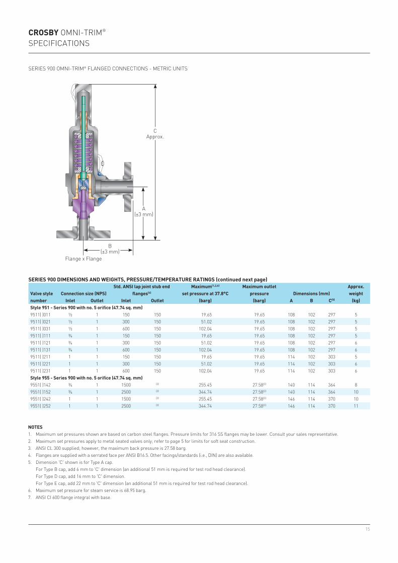
9511( )011 ½ 1 150 150 19.65 19.65 108 102 297 59511( )021 ½ 1 300 150 51.02 19.65 108 102 297 59511( )031 ½ 1 600 150 102.04 19.65 108 102 297 59511( )111 ¾ 1 150 150 19.65 19.65 108 102 297 59511( )121 ¾ 1 300 150 51.02 19.65 108 102 297 69511( )131 ¾ 1 600 150 102.04 19.65 108 102 297 69511( )211 1 1 150 150 19.65 19.65 114 102 303 59511( )221 1 1 300 150 51.02 19.65 114 102 303 69511( )231 1 1 600 150 102.04 19.65 114 102 303 6
9551( )142 ¾ 1 1500 (3) 255.45 27.58(3) 140 114 364 89551( )152 ¾ 1 2500 (3) 344.74 27.58(3) 140 114 364 109551( )242 1 1 1500 (3) 255.45 27.58(3) 146 114 370 109551( )252 1 1 2500 (3) 344.74 27.58(3) 146 114 370 11
CROSBY OMNI-TRIM® SPECIFICATIONS
SERIES 900 OMNI-TRIM® FLANGED CONNECTIONS - METRIC UNITS
SERIES 900 DIMENSIONS AND WEIGHTS, PRESSURE/TEMPERATURE RATINGS (continued next page)
Valve style number
Connection size (NPS)Std. ANSI lap joint stub end
flanges(4)
Maximum(1,2,6)
set pressure at 37.8°CMaximum outlet
pressure Dimensions (mm)Approx.weight
Inlet Outlet Inlet Outlet (barg) (barg) A B C(5) (kg)Style 951 - Series 900 with no. 5 orifice (47.74 sq. mm)
Style 955 - Series 900 with no. 5 orifice (47.74 sq. mm)
Flange x Flange
CApprox.
NOTES1. Maximum set pressures shown are based on carbon steel flanges. Pressure limits for 316 SS flanges may be lower. Consult your sales representative.2. Maximum set pressures apply to metal seated valves only; refer to page 5 for limits for soft seat construction.3. ANSI CL 300 supplied; however, the maximum back pressure is 27.58 barg.4. Flanges are supplied with a serrated face per ANSI B16.5. Other facings/standards (i.e., DIN) are also available.5. Dimension 'C' shown is for Type A cap. For Type B cap, add 6 mm to 'C' dimension (an additional 51 mm is required for test rod head clearance). For Type D cap, add 16 mm to 'C' dimension. For Type E cap, add 22 mm to 'C' dimension (an additional 51 mm is required for test rod head clearance).6. Maximum set pressure for steam service is 68.95 barg.7. ANSI CI 600 flange integral with base.
16
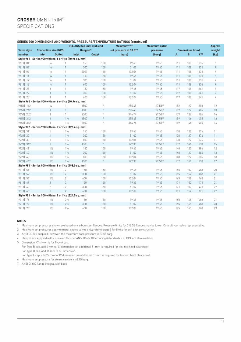
9651( )142 ¾ 1 1500 (3) 255.45 27.58(3) 152 127 398 129651( )242 1 1 1500 (3) 255.45 27.58(3) 159 127 405 139651( )252 1 1 2500 (3) 344.74 27.58(3) 159 127 405 149651( )342 1 1½ 1500 (3) 255.45 27.58(3) 159 146 405 139651( )352 1 1½ 2500 (3) 344.74 27.58(3) 159 146 405 16
9721( )311 1 1½ 150 150 19.65 19.65 130 127 376 119721( )321 1 1½ 300 150 51.02 19.65 130 127 376 119721( )331 1 1½ 600 150 102.04 19.65 130 127 376 119721( )342 1 1½ 1500 (3) 172.36 27.58(3) 152 146 398 159721( )411 1½ 1½ 150 150 19.65 19.65 140 127 386 129721( )421 1½ 1½ 300 150 51.02 19.65 140 127 386 139721( )431 1½ 1½ 600 150 102.04 19.65 140 127 386 139721( )442 1½ 1½ 1500 (3) 172.36 27.58(3) 152 146 398 17
9811( )511 1½ 2 150 150 19.65 19.65 165 152 468 209811( )521 1½ 2 300 150 51.02 19.65 165 152 468 219811( )531 1½ 2 600 150 102.04 19.65 165 152 468 219811( )611 2 2 150 150 19.65 19.65 171 152 475 219811( )621 2 2 300 150 51.02 19.65 171 152 475 229811( )631 2 2 600 150 102.04 19.65 171 152 475 22
9911( )711 1½ 2½ 150 150 19.65 19.65 165 165 468 219911( )721 1½ 2½ 300 150 51.02 19.65 165 165 468 239911( )731 1½ 2½ 600 150 102.04 19.65 165 165 468 23
9611( )011 ½ 1 150 150 19.65 19.65 111 108 335 69611( )021 ½ 1 300 150 51.02 19.65 111 108 335 79611( )031 ½ 1 6007 150 102.04 19.65 111 108 335 79611( )111 ¾ 1 150 150 19.65 19.65 111 108 335 69611( )121 ¾ 1 300 150 51.02 19.65 111 108 335 79611( )131 ¾ 1 600 150 102.04 19.65 111 108 335 79611( )211 1 1 150 150 19.65 19.65 117 108 341 79611( )221 1 1 300 150 51.02 19.65 117 108 341 79611( )231 1 1 600 150 102.04 19.65 117 108 341 7
CROSBY OMNI-TRIM® SPECIFICATIONS
NOTES1. Maximum set pressures shown are based on carbon steel flanges. Pressure limits for 316 SS flanges may be lower. Consult your sales representative.2. Maximum set pressures apply to metal seated valves only; refer to page 5 for limits for soft seat construction.3. ANSI CL 300 supplied; however, the maximum back pressure is 27.58 barg.4. Flanges are supplied with a serrated face per ANSI B16.5. Other facings/standards (i.e., DIN) are also available.5. Dimension 'C' shown is for Type A cap. For Type B cap, add 6 mm to 'C' dimension (an additional 51 mm is required for test rod head clearance). For Type D cap, add 16 mm to 'C' dimension. For Type E cap, add 22 mm to 'C' dimension (an additional 51 mm is required for test rod head clearance).6. Maximum set pressure for steam service is 68.95 barg.7. ANSI CI 600 flange integral with base.
Style 972 - Series 900 with no. 7 orifice (126.4 sq. mm)
Style 981 - Series 900 with no. 8 orifice (198.0 sq. mm)
Style 991 - Series 900 with no. 9 orifice (324.5 sq. mm)
SERIES 900 DIMENSIONS AND WEIGHTS, PRESSURE/TEMPERATURE RATINGS (continued)
Valve style number
Connection size (NPS)Std. ANSI lap joint stub end
flanges(4)
Maximum(1,2,6)
set pressure at 37.8°CMaximum outlet
pressure Dimensions (mm)Approx.weight
Inlet Outlet Inlet Outlet (barg) (barg) A B C(5) (kg)Style 961 - Series 900 with no. 6 orifice (70.96 sq. mm)
Style 965 - Series 900 with no. 6 orifice (70.96 sq. mm)
17
A±⅛"
(±3 mm)
A±⅛"
(±3 mm)
MNPT x FNPT FNPT x FNPT
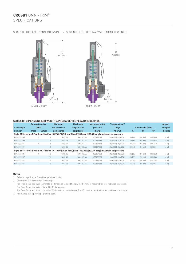
BP51( )( )1MF ¾ 1 50 (3.45) 1500 (103.44) 400 (27.58) -20/+400 (-28/+204) 3⅜ (86) 2½ (64) 13⅜ (340) 14 (6)BP51( )( )2MF 1 1 50 (3.45) 1500 (103.44) 400 (27.58) -20/+400 (-28/+204) 3⅝ (92) 2½ (64) 13⅝ (346) 14 (6)BP51( )( )1FF ¾ 1 50 (3.45) 1500 (103.44) 400 (27.58) -20/+400 (-28/+204) 2¾ (70) 2½ (64) 12¾ (324) 14 (6)
BP51( )( )2FF 1 1 50 (3.45) 1500 (103.44) 400 (27.58) -20/+400 (-28/+204) 3 (736) 2½ (64) 13 (330) 14 (6)
BP61( )( )1MF ¾ 1½ 50 (3.45) 1500 (103.44) 400 (27.58) -20/+400 (-28/+204) 3⅜ (86) 2½ (64) 13⅜ (340) 14 (6)
BP61( )( )2MF 1 1½ 50 (3.45) 1500 (103.44) 400 (27.58) -20/+400 (-28/+204) 3⅝ (92) 2½ (64) 13⅝ (346) 14 (6)
BP61( )( )1FF ¾ 1½ 50 (3.45) 1500 (103.44) 400 (27.58) -20/+400 (-28/+204) 2¾ (70) 2½ (64) 12¾ (324) 14 (6)BP61( )( )2FF 1 1½ 50 (3.45) 1500 (103.44) 400 (27.58) -20/+400 (-28/+204) 3 (736) 2½ (64) 13 (330) 14 (6)
CROSBY OMNI-TRIM® SPECIFICATIONS
NOTES1. Refer to page 7 for soft seat temperature limits.2. Dimension 'C' shown is for Type A cap. For Type B cap, add ¼ in. (6 mm) to 'C' dimension (an additional 2 in. (51 mm) is required for test rod head clearance). For Type D cap, add ⅝ in. (16 mm) to 'C' dimension. For Type E cap, add ⅞ in. (22 mm) to 'C' dimension (an additional 2 in. (51 mm) is required for test rod head clearance).3. Add 1.6 lbs (0.7 kg) for Type D and E caps.
SERIES BP THREADED CONNECTIONS (NPT) - USCS UNITS (U.S. CUSTOMARY SYSTEM) (METRIC UNITS)
CApprox.
CApprox.
Style BP6 - series BP with no. 6 orifice (0.110 in2 [70.96 mm2]) and 1500 psig (103.44 barg) maximum set pressure
SERIES BP DIMENSIONS AND WEIGHTS, PRESSURE/TEMPERATURE RATINGS
Valve style number
Connection size (NPS)
Minimum set pressure
Maximum set pressure
Maximum outlet pressure
Temperature(1) range Dimensions (mm)
Approx.weight(3)
Inlet Outlet psig (barg) psig (barg) (barg) °F (°C) A B C(2) lbs (kg)Style BP5 - series BP with no. 5 orifice (0.074 in2 [47.7 mm2]) and 1500 psig (103.44 barg) maximum set pressure
18
A±⅛"
(±3 mm)
B±⅛"
(±3 mm)
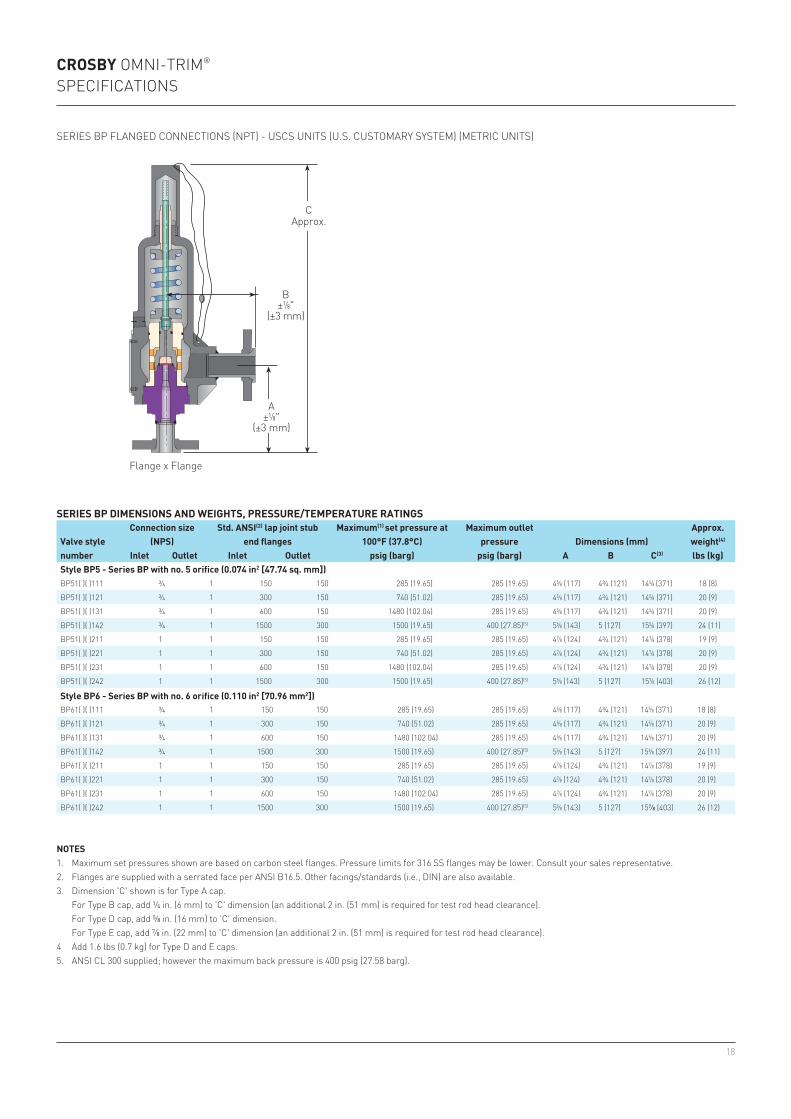
BP51( )( )111 ¾ 1 150 150 285 (19.65) 285 (19.65) 4⅝ (117) 4¾ (121) 14⅝ (371) 18 (8)
BP51( )( )121 ¾ 1 300 150 740 (51.02) 285 (19.65) 4⅝ (117) 4¾ (121) 14⅝ (371) 20 (9)
BP51( )( )131 ¾ 1 600 150 1480 (102.04) 285 (19.65) 4⅝ (117) 4¾ (121) 14⅝ (371) 20 (9)
BP51( )( )142 ¾ 1 1500 300 1500 (19.65) 400 (27.85)(5) 5⅝ (143) 5 (127) 15⅝ (397) 24 (11)
BP51( )( )211 1 1 150 150 285 (19.65) 285 (19.65) 4⅞ (124) 4¾ (121) 14⅞ (378) 19 (9)
BP51( )( )221 1 1 300 150 740 (51.02) 285 (19.65) 4⅞ (124) 4¾ (121) 14⅞ (378) 20 (9)
BP51( )( )231 1 1 600 150 1480 (102.04) 285 (19.65) 4⅞ (124) 4¾ (121) 14⅞ (378) 20 (9)
BP51( )( )242 1 1 1500 300 1500 (19.65) 400 (27.85)(5) 5⅝ (143) 5 (127) 15⅞ (403) 26 (12)
BP61( )( )111 ¾ 1 150 150 285 (19.65) 285 (19.65) 4⅝ (117) 4¾ (121) 14⅝ (371) 18 (8)
BP61( )( )121 ¾ 1 300 150 740 (51.02) 285 (19.65) 4⅝ (117) 4¾ (121) 14⅝ (371) 20 (9)
BP61( )( )131 ¾ 1 600 150 1480 (102.04) 285 (19.65) 4⅝ (117) 4¾ (121) 14⅝ (371) 20 (9)
BP61( )( )142 ¾ 1 1500 300 1500 (19.65) 400 (27.85)(5) 5⅝ (143) 5 (127) 15⅝ (397) 24 (11)
BP61( )( )211 1 1 150 150 285 (19.65) 285 (19.65) 4⅞ (124) 4¾ (121) 14⅞ (378) 19 (9)
BP61( )( )221 1 1 300 150 740 (51.02) 285 (19.65) 4⅞ (124) 4¾ (121) 14⅞ (378) 20 (9)
BP61( )( )231 1 1 600 150 1480 (102.04) 285 (19.65) 4⅞ (124) 4¾ (121) 14⅞ (378) 20 (9)
BP61( )( )242 1 1 1500 300 1500 (19.65) 400 (27.85)(5) 5⅝ (143) 5 (127) 15⅞ (403) 26 (12)
CROSBY OMNI-TRIM® SPECIFICATIONS
Flange x Flange
SERIES BP FLANGED CONNECTIONS (NPT) - USCS UNITS (U.S. CUSTOMARY SYSTEM) (METRIC UNITS)
CApprox.
SERIES BP DIMENSIONS AND WEIGHTS, PRESSURE/TEMPERATURE RATINGS
Valve style number
Connection size (NPS)
Std. ANSI(2) lap joint stub end flanges
Maximum(1) set pressure at 100°F (37.8°C)
Maximum outlet pressure Dimensions (mm)
Approx.weight(4)
Inlet Outlet Inlet Outlet psig (barg) psig (barg) A B C(3) lbs (kg)Style BP5 - Series BP with no. 5 orifice (0.074 in2 [47.74 sq. mm])
Style BP6 - Series BP with no. 6 orifice (0.110 in2 [70.96 mm2])
NOTES1. Maximum set pressures shown are based on carbon steel flanges. Pressure limits for 316 SS flanges may be lower. Consult your sales representative.2. Flanges are supplied with a serrated face per ANSI B16.5. Other facings/standards (i.e., DIN) are also available.3. Dimension 'C' shown is for Type A cap. For Type B cap, add ¼ in. (6 mm) to 'C' dimension (an additional 2 in. (51 mm) is required for test rod head clearance). For Type D cap, add ⅝ in. (16 mm) to 'C' dimension. For Type E cap, add ⅞ in. (22 mm) to 'C' dimension (an additional 2 in. (51 mm) is required for test rod head clearance).4 Add 1.6 lbs (0.7 kg) for Type D and E caps.5. ANSI CL 300 supplied; however the maximum back pressure is 400 psig (27.58 barg).
19
5 34.2 50.4 280 438 645 1140 1801 29436 35.7 52.6 93.0 300 468 689 1218 1924 31447 37.2 54.8 96.9 153 250 320 498 733 1295 2047 33448 38.7 57.1 100 159 260 340 528 777 1373 2170 35459 40.3 59.3 104 165 270 360 557 821 1451 2293 374610 41.8 61.5 108 171 280 380 587 865 1528 2415 394615 44.4 65.3 115 182 298 400 617 909 1606 2538 414720 51.2 75.3 133 210 343 420 647 953 1684 2661 434830 64.7 95.3 168 266 435 440 677 997 1762 2784 454840 79.7 117 207 327 535 460 707 1041 1839 2907 474950 94.6 139 246 389 635 480 737 1085 1917 3030 495060 109 161 285 450 736 500 767 1129 1995 3152 515170 124 183 324 511 836 520 797 1173 2073 3275 535180 139 205 362 573 936 540 826 1217 2150 3398 555290 154 227 401 634 1037 560 856 1261 2228 3521 5753100 169 249 440 696 1137 580 886 1305 2306 3644 5953120 199 293 518 819 1338 600 916 1349 2384 3767 6154140 229 337 596 941 1538 620 946 1393 2461 3889 6355160 259 381 673 1064 1739 640 976 1437 2539 4012 6555180 288 425 751 1187 1940 660 1006 1481 2617 4135 6756200 318 469 829 1310 2140 680 1036 1525 2695 4258 6957220 348 513 907 1433 2341 700 1065 1569 2772 4381 7157240 378 557 984 1556 2542 720 1095 1613 2850 4504 7358260 408 601 1062 1678 2742 740 1125 1657 2928 4626 7559
CROSBY OMNI-TRIM® AIR CAPACITIES
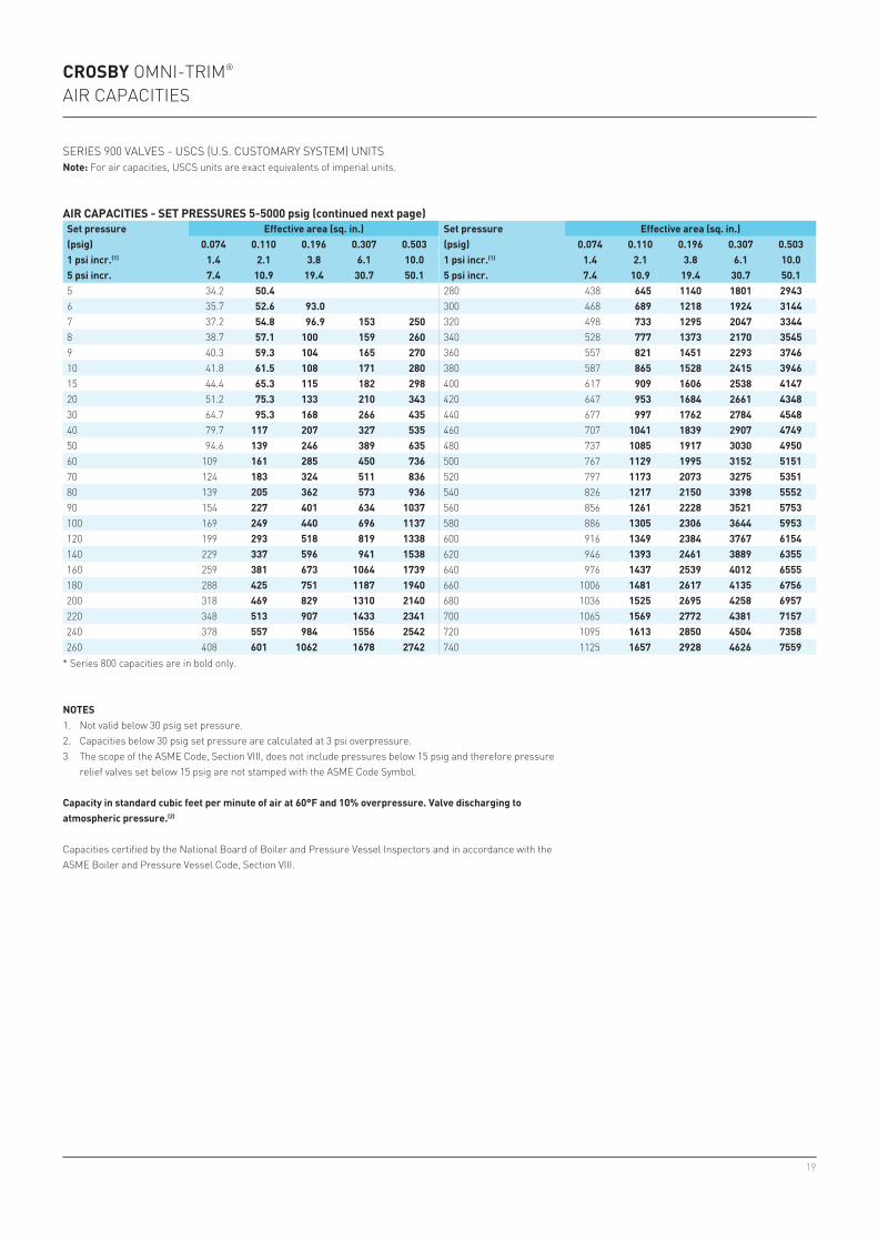
SERIES 900 VALVES - USCS (U.S. CUSTOMARY SYSTEM) UNITSNote: For air capacities, USCS units are exact equivalents of imperial units.
* Series 800 capacities are in bold only.
NOTES1. Not valid below 30 psig set pressure.2. Capacities below 30 psig set pressure are calculated at 3 psi overpressure.3 The scope of the ASME Code, Section VIII, does not include pressures below 15 psig and therefore pressure
relief valves set below 15 psig are not stamped with the ASME Code Symbol.
Capacity in standard cubic feet per minute of air at 60°F and 10% overpressure. Valve discharging to atmospheric pressure.(2)
Capacities certified by the National Board of Boiler and Pressure Vessel Inspectors and in accordance with the ASME Boiler and Pressure Vessel Code, Section VIII.
AIR CAPACITIES - SET PRESSURES 5-5000 psig (continued next page)Set pressure (psig)
Effective area (sq. in.) Set pressure (psig)
Effective area (sq. in.)0.074 0.110 0.196 0.307 0.503 0.074 0.110 0.196 0.307 0.503
1 psi incr.(1) 1.4 2.1 3.8 6.1 10.0 1 psi incr.(1) 1.4 2.1 3.8 6.1 10.05 psi incr. 7.4 10.9 19.4 30.7 50.1 5 psi incr. 7.4 10.9 19.4 30.7 50.1
20
760 1155 1701 3006 4749 7759 2200 3307 4869 8603780 1185 1745 3083 4872 7960 2300 3456 5089 8991800 1215 1789 3161 4995 8161 2400 3606 5309 9380820 1245 1833 3239 5118 8361 2500 3755 5529 9769840 1275 1877 3316 5241 8562 2600 3905 5749860 1305 1921 3394 5363 8763 2700 4054 5969880 1334 1965 3472 5486 8963 2800 4203 6189900 1364 2009 3550 5609 9164 2900 4353 6409920 1394 2053 3627 5732 9365 3000 4502 6629940 1424 2097 3705 5855 9565 3100 4652 6849960 1454 2141 3783 5978 9766 3200 4801 7069980 1484 2185 3861 6100 9967 3300 4951 72881000 1514 2229 3938 6223 10167 3400 5100 75081100 1663 2449 4327 6837 11171 3500 5249 77281200 1813 2669 4716 7452 12174 3600 5399 79481300 1962 2889 5104 8066 13178 3700 5548 81681400 2111 3109 5493 8680 14181 3800 5698 83881500 2261 3329 5882 9294 15184 3900 5847 86081600 2410 3549 6271 4000 5997 88281700 2560 3769 6659 4200 6295 92681800 2709 3989 7048 4400 6594 97081900 2859 4209 7437 4600 6893 101482000 3008 4429 7825 4800 7192 105882100 3157 4649 8214 5000 7491 11028
CROSBY OMNI-TRIM® AIR CAPACITIES
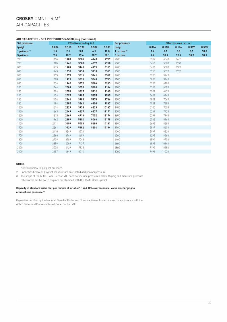
NOTES1. Not valid below 30 psig set pressure.2. Capacities below 30 psig set pressure are calculated at 3 psi overpressure.3 The scope of the ASME Code, Section VIII, does not include pressures below 15 psig and therefore pressure
relief valves set below 15 psig are not stamped with the ASME Code Symbol.
Capacity in standard cubic feet per minute of air at 60°F and 10% overpressure. Valve discharging to atmospheric pressure.(2)
Capacities certified by the National Board of Boiler and Pressure Vessel Inspectors and in accordance with the ASME Boiler and Pressure Vessel Code, Section VIII.
AIR CAPACITIES - SET PRESSURES 5-5000 psig (continued)Set pressure (psig)
Effective area (sq. in.) Set pressure (psig)
Effective area (sq. in.)0.074 0.110 0.196 0.307 0.503 0.074 0.110 0.196 0.307 0.503
1 psi incr.(1) 1.4 2.1 3.8 6.1 10.0 1 psi incr.(1) 1.4 2.1 3.8 6.1 10.05 psi incr. 7.4 10.9 19.4 30.7 50.1 5 psi incr. 7.4 10.9 19.4 30.7 50.1
21
5 96.2 141 160 727 1071 1893 2991 48876 100 147 261 170 769 1133 2002 3163 51687 104 154 272 180 811 1195 2111 3336 54508 108 160 283 447 731 190 853 1256 2220 3508 57329 113 166 294 465 760 200 895 1318 2329 3681 601410 117 172 305 482 788 210 937 1380 2439 3854 629615 124 183 324 512 837 220 979 1442 2548 4026 657820 143 211 374 591 966 230 1021 1504 2657 4199 686030 182 268 473 748 1222 240 1063 1565 2766 4371 714240 224 329 582 920 1504 250 1105 1627 2875 4544 742450 266 391 691 1093 1786 260 1147 1689 2985 4716 770660 307 453 801 1265 2068 270 1189 1751 3094 4889 798770 349 515 910 1438 2349 280 1231 1813 3203 5061 826980 391 577 1019 1610 2631 290 1273 1874 3312 5234 855190 433 638 1128 1783 2913 300 1315 1936 3421 5406 8833100 475 700 1237 1956 3195 310 1357 1998 3531 5579 9115110 517 762 1347 2128 3477 320 1399 2060 3640 5752 9397120 559 824 1456 2301 3759 330 1441 2122 3749 5924 9679130 601 886 1565 2473 4041 340 1483 2183 3858 6097 9961140 643 947 1674 2646 4323 350 1525 2245 3967 6269 10243150 685 1009 1783 2818 4605 360 1567 2307 4077 6442 10524
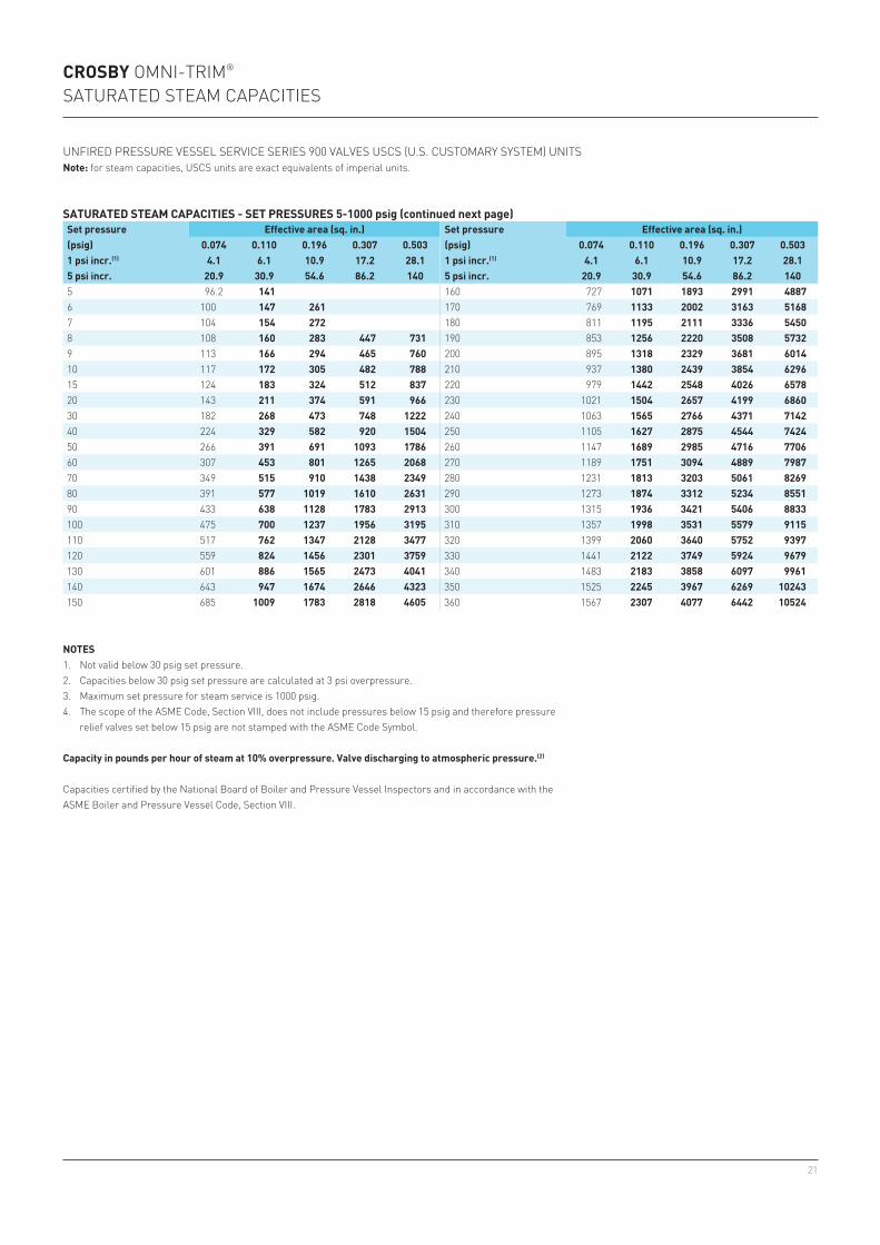
CROSBY OMNI-TRIM® SATURATED STEAM CAPACITIES
UNFIRED PRESSURE VESSEL SERVICE SERIES 900 VALVES USCS (U.S. CUSTOMARY SYSTEM) UNITSNote: for steam capacities, USCS units are exact equivalents of imperial units.
NOTES1. Not valid below 30 psig set pressure.2. Capacities below 30 psig set pressure are calculated at 3 psi overpressure.3. Maximum set pressure for steam service is 1000 psig.4. The scope of the ASME Code, Section VIII, does not include pressures below 15 psig and therefore pressure
relief valves set below 15 psig are not stamped with the ASME Code Symbol.
Capacity in pounds per hour of steam at 10% overpressure. Valve discharging to atmospheric pressure.(2)
Capacities certified by the National Board of Boiler and Pressure Vessel Inspectors and in accordance with the ASME Boiler and Pressure Vessel Code, Section VIII.
SATURATED STEAM CAPACITIES - SET PRESSURES 5-1000 psig (continued next page)Set pressure (psig)
Effective area (sq. in.) Set pressure (psig)
Effective area (sq. in.)0.074 0.110 0.196 0.307 0.503 0.074 0.110 0.196 0.307 0.503
1 psi incr.(1) 4.1 6.1 10.9 17.2 28.1 1 psi incr.(1) 4.1 6.1 10.9 17.2 28.15 psi incr. 20.9 30.9 54.6 86.2 140 5 psi incr. 20.9 30.9 54.6 86.2 140
22
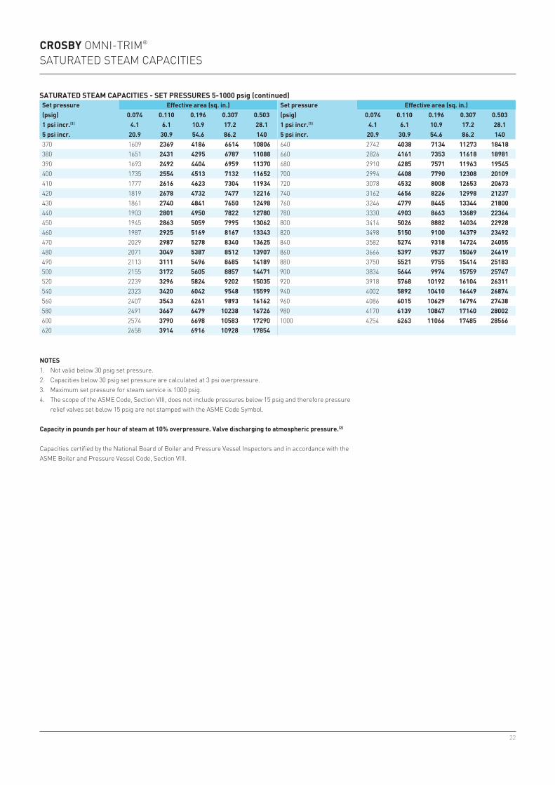
370 1609 2369 4186 6614 10806 640 2742 4038 7134 11273 18418380 1651 2431 4295 6787 11088 660 2826 4161 7353 11618 18981390 1693 2492 4404 6959 11370 680 2910 4285 7571 11963 19545400 1735 2554 4513 7132 11652 700 2994 4408 7790 12308 20109410 1777 2616 4623 7304 11934 720 3078 4532 8008 12653 20673420 1819 2678 4732 7477 12216 740 3162 4656 8226 12998 21237430 1861 2740 4841 7650 12498 760 3246 4779 8445 13344 21800440 1903 2801 4950 7822 12780 780 3330 4903 8663 13689 22364450 1945 2863 5059 7995 13062 800 3414 5026 8882 14034 22928460 1987 2925 5169 8167 13343 820 3498 5150 9100 14379 23492470 2029 2987 5278 8340 13625 840 3582 5274 9318 14724 24055480 2071 3049 5387 8512 13907 860 3666 5397 9537 15069 24619490 2113 3111 5496 8685 14189 880 3750 5521 9755 15414 25183500 2155 3172 5605 8857 14471 900 3834 5644 9974 15759 25747520 2239 3296 5824 9202 15035 920 3918 5768 10192 16104 26311540 2323 3420 6042 9548 15599 940 4002 5892 10410 16449 26874560 2407 3543 6261 9893 16162 960 4086 6015 10629 16794 27438580 2491 3667 6479 10238 16726 980 4170 6139 10847 17140 28002600 2574 3790 6698 10583 17290 1000 4254 6263 11066 17485 28566620 2658 3914 6916 10928 17854
NOTES1. Not valid below 30 psig set pressure.2. Capacities below 30 psig set pressure are calculated at 3 psi overpressure.3. Maximum set pressure for steam service is 1000 psig.4. The scope of the ASME Code, Section VIII, does not include pressures below 15 psig and therefore pressure
relief valves set below 15 psig are not stamped with the ASME Code Symbol.
Capacity in pounds per hour of steam at 10% overpressure. Valve discharging to atmospheric pressure.(2)
Capacities certified by the National Board of Boiler and Pressure Vessel Inspectors and in accordance with the ASME Boiler and Pressure Vessel Code, Section VIII.
CROSBY OMNI-TRIM® SATURATED STEAM CAPACITIES
SATURATED STEAM CAPACITIES - SET PRESSURES 5-1000 psig (continued)Set pressure(psig)
Effective area (sq. in.) Set pressure(psig)
Effective area (sq. in.)0.074 0.110 0.196 0.307 0.503 0.074 0.110 0.196 0.307 0.503
1 psi incr.(1) 4.1 6.1 10.9 17.2 28.1 1 psi incr.(1) 4.1 6.1 10.9 17.2 28.15 psi incr. 20.9 30.9 54.6 86.2 140 5 psi incr. 20.9 30.9 54.6 86.2 140
23
5 4.7 6.9 420 43.5 64.0 113 178 29210 6.7 9.8 17.4 440 44.5 65.5 115 183 29915 8.2 12.1 21.3 33.8 55.2 460 45.5 67.0 118 187 30520 9.4 13.9 24.7 39.0 63.7 480 46.5 68.5 121 191 31230 11.6 17.1 30.2 47.8 78.1 500 47.4 69.9 123 195 31840 13.4 19.7 34.9 55.2 90.2 520 48.4 71.3 125 199 32550 15.0 22.1 39.0 61.7 100 540 49.3 72.6 128 202 33160 16.4 24.2 42.7 67.6 110 560 50.2 73.9 130 206 33780 18.9 27.9 49.4 78.0 127 580 51.1 75.3 133 210 343100 21.2 31.2 55.2 87.2 142 600 52.0 76.5 135 213 349120 23.2 34.2 60.5 95.6 156 620 52.8 77.8 137 217 355140 25.1 36.9 65.3 103 168 640 53.7 79.1 139 220 360160 26.8 39.5 69.8 110 180 660 54.5 80.3 141 224 366180 28.4 41.9 74.1 117 191 680 55.3 81.5 144 227 371200 30.0 44.2 78.1 123 201 700 56.1 82.7 146 230 377220 31.5 46.3 81.9 129 211 720 56.9 83.9 148 234 382240 32.9 48.4 85.5 135 220 740 57.7 85.0 150 237 387260 34.2 50.4 89.0 140 229 760 58.5 86.2 152 240 393280 35.5 52.3 92.4 146 238 780 59.3 87.3 154 243 398300 36.7 54.1 95.6 151 247 800 60.0 88.4 156 246 403320 37.9 55.9 98.8 156 255 820 60.8 89.5 158 249 408340 39.1 57.6 101 160 262 840 61.5 90.6 160 253 413360 40.3 59.3 104 165 270 860 62.2 91.7 162 256 418380 41.4 60.9 107 170 278 880 63.0 92.7 163 258 423400 42.4 62.5 110 174 285 900 63.7 93.8 165 261 427
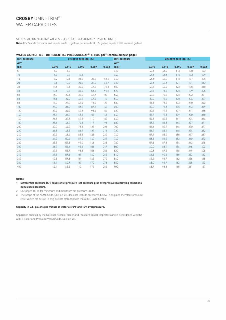
CROSBY OMNI-TRIM® WATER CAPACITIES
SERIES 900 OMNI-TRIM® VALVES - USCS (U.S. CUSTOMARY SYSTEM) UNITSNote: USCS units for water and liquids are U.S. gallons per minute (1 U.S. gallon equals 0.833 imperial gallon).
NOTES1. Differential pressure (ΔP) equals inlet pressure (set pressure plus overpressure) at flowing conditions
minus back pressure.2. See pages 15-18 for minimum and maximum set pressure limits.3. The scope of the ASME Code, Section VIII, does not include pressures below 15 psig and therefore pressure
relief valves set below 15 psig are not stamped with the ASME Code Symbol.
Capacity in U.S. gallons per minute of water at 70°F and 10% overpressure.
Capacities certified by the National Board of Boiler and Pressure Vessel Inspectors and in accordance with the ASME Boiler and Pressure Vessel Code, Section VIII.
WATER CAPACITIES - DIFFERENTIAL PRESSURES ΔP(1) 5-5000 psi(2) (continued next page)Diff. pressure Effective area (sq. in.) Diff. pressure Effective area (sq. in.)ΔP(1) ΔP(1)
(psi) 0.074 0.110 0.196 0.307 0.503 (psi) 0.074 0.110 0.196 0.307 0.503
24
920 64.4 94.8 167 264 432 3100 118 174940 65.1 95.8 169 267 437 3200 120 176960 65.8 96.8 171 270 441 3300 122 179980 66.4 97.8 172 273 446 3400 123 1821000 67.1 98.8 174 276 451 3500 125 1841100 70.4 103 183 289 473 3600 127 1871200 73.5 108 191 302 494 3700 129 1901300 76.5 112 199 314 514 3800 130 1921400 79.4 116 206 326 533 3900 132 1951500 82.2 121 213 338 552 4000 134 1971600 84.9 125 220 349 570 4100 136 2001700 87.5 128 227 4200 137 2021800 90.1 132 234 4300 139 2051900 92.5 136 240 4400 140 2072000 94.9 139 247 4500 142 2092100 97.3 143 253 4600 144 2122200 99.6 146 259 4700 145 2142300 101 149 264 4800 147 2162400 104 153 270 4900 148 2182500 106 156 276 5000 150 2212600 108 159 2812700 110 162 2872800 112 1652900 114 1683000 116 171
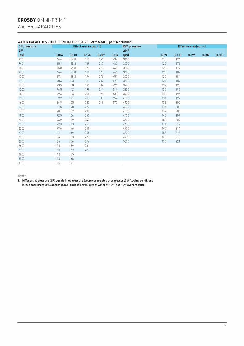
CROSBY OMNI-TRIM® WATER CAPACITIES
NOTES1. Differential pressure (ΔP) equals inlet pressure (set pressure plus overpressure) at flowing conditions
minus back pressure.Capacity in U.S. gallons per minute of water at 70°F and 10% overpressure.
WATER CAPACITIES - DIFFERENTIAL PRESSURES ΔP(1) 5-5000 psi(2) (continued)Diff. pressure Effective area (sq. in.) Diff. pressure Effective area (sq. in.)ΔP(1) ΔP(1)
(psi) 0.074 0.110 0.196 0.307 0.503 (psi) 0.074 0.110 0.196 0.307 0.503
25
0.35 0.98 1.45 2.57 35 22 14.2 21.0 37.1 58.7 95.9 2200
0.4 1.01 1.50 2.65 4.19 40 24 15.5 22.8 40.3 63.8 104 2400
0.45 1.05 1.54 2.73 4.32 45 26 16.7 24.6 43.6 68.9 112 2600
0.5 1.08 1.59 2.81 4.45 7.27 50 28 18.0 26.5 46.8 74.0 121 2800
0.55 1.11 1.64 2.89 4.58 7.48 55 30 19.2 28.3 50.1 79.1 129 3000
0.6 1.14 1.68 2.98 4.70 7.69 60 32 20.5 30.2 53.3 84.3 137 3200
0.65 1.17 1.73 3.06 4.83 7.90 65 34 21.7 32.0 56.6 89.4 146 3400
0.7 1.20 1.77 3.14 4.96 8.11 70 36 23.0 33.8 59.8 94.5 154 3600
0.75 1.24 1.82 3.22 5.09 8.32 75 38 24.2 35.7 63.0 99.6 162 3800
0.8 1.27 1.87 3.30 5.22 8.53 80 40 25.5 37.5 66.3 104 171 4000
0.85 1.30 1.91 3.38 5.35 8.75 85 42 26.7 39.3 69.5 109 179 4200
0.9 1.33 1.96 3.47 5.48 8.96 90 44 27.9 41.2 72.8 115 187 4400
0.95 1.36 2.01 3.55 5.61 9.17 95 46 29.2 43.0 76.0 120 196 4600
1 1.39 2.05 3.63 5.74 9.38 100 48 30.4 44.8 79.2 125 204 4800
2 1.80 2.60 4.70 7.40 12.2 200 50 31.7 46.7 82.5 130 213 5000
4 3.00 4.50 7.90 12.6 20.5 400 52 32.9 48.5 85.7 135 221 5200
6 4.30 6.30 11.2 17.7 28.9 600 54 34.2 50.3 89.0 140 229 5400
8 5.50 8.10 14.4 22.8 37.3 800 56 35.4 52.2 92.2 145 238 5600
10 6.80 10.0 17.7 27.9 45.6 1000 58 36.7 54.0 95.5 150 246 5800
12 8.00 11.8 20.9 33.0 54.0 1200 60 37.9 55.8 98.7 156 254 6000
14 9.20 13.6 24.1 38.2 62.4 1400 62 39.2 57.7 101 161 263 6200
16 10.5 15.5 27.4 43.3 70.8 1600 64 40.4 59.5 105 166 271 6400
18 11.7 17.3 30.6 48.4 79.1 1800 66 41.7 61.3 108 171 280 6600
20 13.0 19.1 33.9 53.5 87.5 2000 68 42.9 63.2 111 176 288 6800
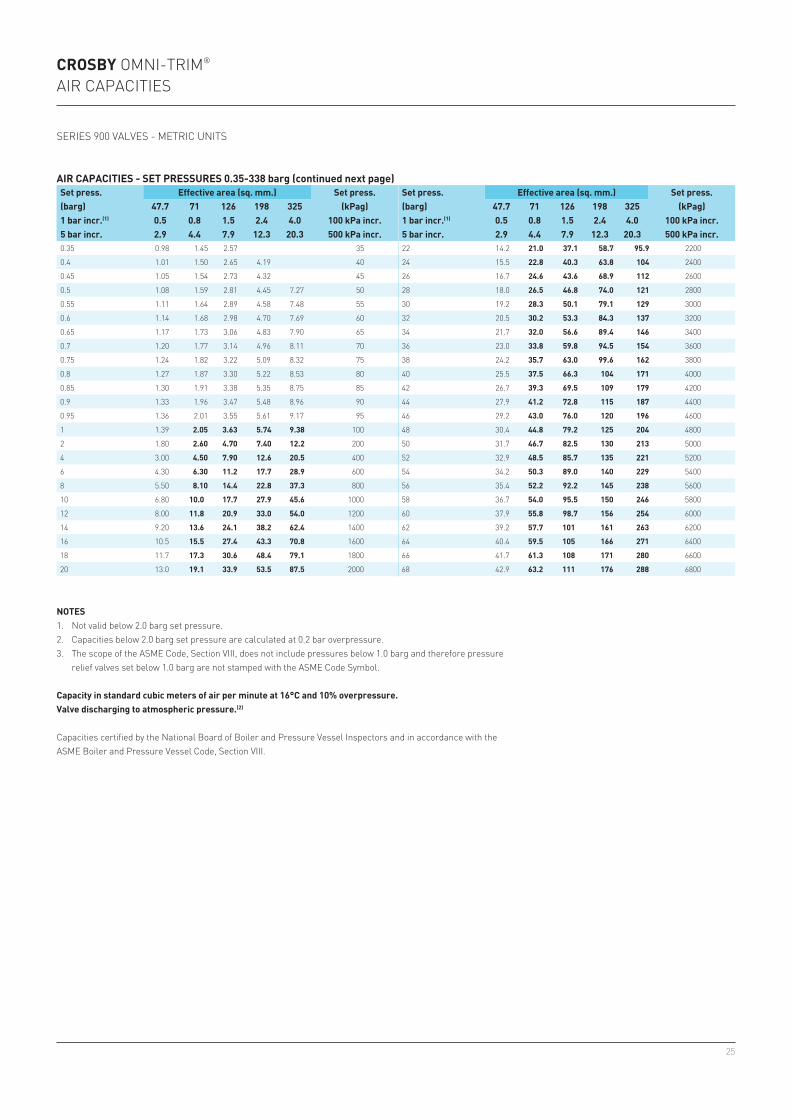
CROSBY OMNI-TRIM® AIR CAPACITIES
SERIES 900 VALVES - METRIC UNITS
NOTES1. Not valid below 2.0 barg set pressure.2. Capacities below 2.0 barg set pressure are calculated at 0.2 bar overpressure.3. The scope of the ASME Code, Section VIII, does not include pressures below 1.0 barg and therefore pressure
relief valves set below 1.0 barg are not stamped with the ASME Code Symbol.
Capacity in standard cubic meters of air per minute at 16°C and 10% overpressure. Valve discharging to atmospheric pressure.(2)
Capacities certified by the National Board of Boiler and Pressure Vessel Inspectors and in accordance with the ASME Boiler and Pressure Vessel Code, Section VIII.
AIR CAPACITIES - SET PRESSURES 0.35-338 barg (continued next page)Set press. Effective area (sq. mm.) Set press. Set press. Effective area (sq. mm.) Set press.(barg) 47.7 71 126 198 325 (kPag) (barg) 47.7 71 126 198 325 (kPag)1 bar incr.(1) 0.5 0.8 1.5 2.4 4.0 100 kPa incr. 1 bar incr.(1) 0.5 0.8 1.5 2.4 4.0 100 kPa incr.5 bar incr. 2.9 4.4 7.9 12.3 20.3 500 kPa incr. 5 bar incr. 2.9 4.4 7.9 12.3 20.3 500 kPa incr.
26
70 44.1 7000 208 130 191 20800
76 47.9 7600 214 133 197 21400
82 51.6 8200 220 137 202 22000
88 55.4 8800 226 141 208 22600
94 59.1 9400 232 145 213 23200
100 62.8 10000 238 148 219 23800
106 66.6 98.0 173 10600 244 152 224 24400
112 70.3 103 183 11200 250 156 230 25000
118 74.1 109 192 11800 256 160 235 25600
124 77.8 114 202 12400 262 163 241 26200
130 81.5 120 212 13000 268 167 246 26800
136 85.3 125 221 13600 274 171 252 27400
142 89.0 131 231 14200 280 175 257 28000
148 92.8 136 241 14800 286 178 263 28600
154 96.5 142 251 15400 292 182 268 29200
160 100 147 260 16000 298 186 274 29800
166 104 153 270 16600 304 190 279 30400
172 107 158 280 17200 310 193 285 31000
178 111 164 17800 316 197 290 31600
184 115 169 18400 322 201 296 32200
190 118 175 19000 328 204 301 32800
196 122 180 19600 334 208 307 33400
202 126 186 20200 338 211 310 33800
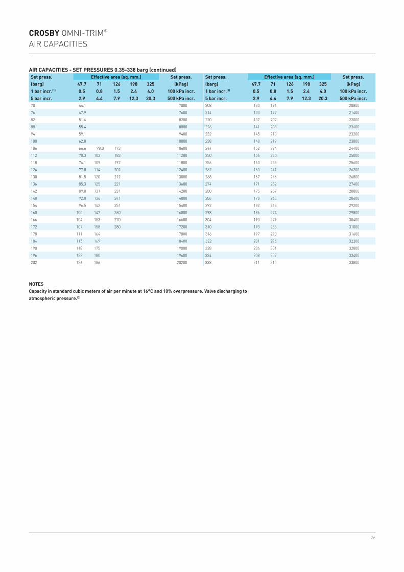
CROSBY OMNI-TRIM® AIR CAPACITIES
NOTESCapacity in standard cubic meters of air per minute at 16°C and 10% overpressure. Valve discharging to atmospheric pressure.(2)
AIR CAPACITIES - SET PRESSURES 0.35-338 barg (continued)Set press. Effective area (sq. mm.) Set press. Set press. Effective area (sq. mm.) Set press.(barg) 47.7 71 126 198 325 (kPag) (barg) 47.7 71 126 198 325 (kPag)1 bar incr.(1) 0.5 0.8 1.5 2.4 4.0 100 kPa incr. 1 bar incr.(1) 0.5 0.8 1.5 2.4 4.0 100 kPa incr.5 bar incr. 2.9 4.4 7.9 12.3 20.3 500 kPa incr. 5 bar incr. 2.9 4.4 7.9 12.3 20.3 500 kPa incr.
27
0.35 43.8 64.4 35 24 688 1013 1790 2828 4621 2400
0.4 45.2 66.5 117 40 25 715 1053 1862 2942 4807 2500
0.45 46.5 68.6 121 45 26 743 1094 1934 3055 4992 2600
0.5 47.9 70.6 124 197 322 50 27 771 1135 2005 3169 5178 2700
0.55 49.3 72.7 128 202 331 55 28 798 1175 2077 3282 5363 2800
0.6 50.7 74.7 132 208 341 60 29 826 1216 2149 3396 5549 2900
0.65 52.1 76.8 135 214 350 65 30 854 1257 2221 3510 5734 3000
0.7 53.5 78.8 139 220 359 70 31 881 1297 2293 3623 5919 3100
0.75 54.9 80.9 142 225 369 75 32 909 1338 2365 3737 6105 3200
0.8 56.3 82.9 146 231 378 80 33 936 1379 2436 3850 6290 3300
0.85 57.7 85.0 150 237 387 85 34 964 1419 2508 3964 6476 3400
0.9 59.1 87.0 153 243 397 90 35 992 1460 2580 4077 6661 3500
0.95 60.5 89.1 157 248 406 95 36 1019 1501 2652 4191 6847 3600
1 61.9 91.1 161 254 415 100 37 1047 1541 2724 4304 7032 3700
1.5 68.3 100 177 280 458 150 38 1074 1582 2796 4418 7218 3800
2 80.6 118 209 331 541 200 39 1102 1623 2868 4531 7403 3900
3 108 159 281 445 727 300 40 1130 1663 2939 4645 7589 4000
4 135 200 353 558 912 400 41 1157 1704 3011 4758 7774 4100
5 163 240 425 672 1098 500 42 1185 1745 3083 4872 7959 4200
6 191 281 497 785 1283 600 43 1213 1785 3155 4985 8145 4300
7 218 322 569 899 1469 700 44 1240 1826 3227 5099 8330 4400
8 246 362 640 1012 1654 800 45 1268 1867 3299 5212 8516 4500
9 274 403 712 1126 1839 900 46 1295 1907 3370 5326 8701 4600
10 301 444 784 1239 2025 1000 47 1323 1948 3442 5439 8887 4700
11 329 484 856 1353 2210 1100 48 1351 1989 3514 5553 9072 4800
12 356 525 928 1466 2396 1200 49 1378 2029 3586 5666 9258 4900
13 384 566 1000 1580 2581 1300 50 1406 2070 3658 5780 9443 5000
14 412 606 1071 1693 2767 1400 52 1461 2151 3801 6007 9814 5200
15 439 647 1143 1807 2952 1500 54 1516 2233 3945 6234 10185 5400
16 467 688 1215 1920 3138 1600 56 1572 2314 4089 6461 10556 5600
17 494 728 1287 2034 3323 1700 58 1627 2395 4232 6688 10927 5800
18 522 769 1359 2147 3509 1800 60 1682 2477 4376 6915 11298 6000
19 550 810 1431 2261 3694 1900 62 1737 2558 4520 7142 11669 6200
20 577 850 1503 2374 3879 2000 64 1793 2639 4664 7369 12039 6400
21 605 891 1574 2488 4065 2100 66 1848 2721 4807 7596 12410 6600
22 633 931 1646 2601 4250 2200 68 1903 2802 4951 7823 12781 6800
23 660 972 1718 2715 4436 2300
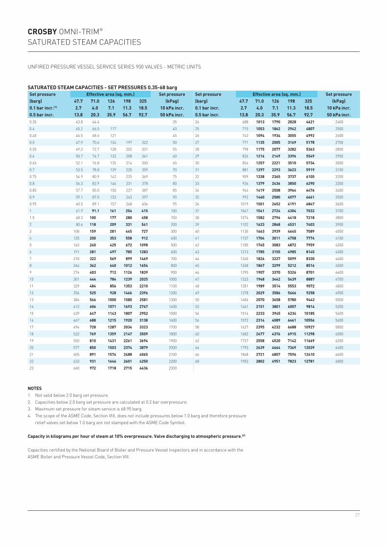
CROSBY OMNI-TRIM® SATURATED STEAM CAPACITIES
UNFIRED PRESSURE VESSEL SERVICE SERIES 900 VALVES - METRIC UNITS
SATURATED STEAM CAPACITIES - SET PRESSURES 0.35-68 bargSet pressure Effective area (sq. mm.) Set pressure Set pressure Effective area (sq. mm.) Set pressure(barg) 47.7 71.0 126 198 325 (kPag) (barg) 47.7 71.0 126 198 325 (kPag)0.1 bar incr.(1) 2.7 4.0 7.1 11.3 18.5 10 kPa incr. 0.1 bar incr. 2.7 4.0 7.1 11.3 18.5 10 kPa incr.0.5 bar incr. 13.8 20.3 35.9 56.7 92.7 50 kPa incr. 0.5 bar incr. 13.8 20.3 35.9 56.7 92.7 50 kPa incr.
NOTES1. Not valid below 2.0 barg set pressure.2. Capacities below 2.0 barg set pressure are calculated at 0.2 bar overpressure.3. Maximum set pressure for steam service is 68.95 barg.4. The scope of the ASME Code, Section VIII, does not include pressures below 1.0 barg and therefore pressure
relief valves set below 1.0 barg are not stamped with the ASME Code Symbol.
Capacity in kilograms per hour of steam at 10% overpressure. Valve discharging to atmospheric pressure.(2)
Capacities certified by the National Board of Boiler and Pressure Vessel Inspectors and in accordance with the ASME Boiler and Pressure Vessel Code, Section VIII.
28
0.4 19.3 28.5 50.3 40 40 193 285 503 795 1300 4000
0.6 23.7 34.9 61.6 97.4 159 60 42 198 292 516 815 1332 4200
0.8 27.3 40.3 71.2 112 183 80 44 203 299 528 834 1363 4400
1 30.6 45.0 79.6 125 205 100 46 207 305 540 853 1394 4600
2 43.3 63.7 112 177 290 200 48 212 312 551 871 1424 4800
4 61.2 90.1 159 251 411 400 50 216 318 563 889 1453 5000
6 75.0 110 195 308 503 600 52 220 325 574 907 1482 5200
8 86.6 127 225 355 581 800 54 225 331 585 924 1510 5400
10 96.8 142 251 397 650 1000 56 229 337 596 941 1538 5600
12 106 156 275 435 712 1200 58 233 343 606 958 1565 5800
14 114 168 298 470 769 1400 60 237 349 616 974 1592 6000
16 122 180 318 503 822 1600 62 241 354 627 990 1618 6200
18 129 191 337 533 872 1800 64 244 360 637 1006 1644 6400
20 136 201 356 562 919 2000 66 248 366 647 1022 1670 6600
22 143 211 373 590 964 2200 68 252 371 656 1037 1695 6800
24 150 220 390 616 1007 2400 70 256 377 666 1052 1720 7000
26 156 229 406 641 1048 2600 76 266 392 694 1097 1792 7600
28 162 238 421 665 1087 2800 82 277 408 721 1139 1861 8200
30 167 246 436 689 1126 3000 88 287 422 747 1180 1928 8800
32 173 255 450 711 1163 3200 94 296 437 772 1220 1993 9400
34 178 262 464 733 1198 3400 100 306 450 796 1258 2056 10000
36 183 270 477 755 1233 3600 106 315 464 820 1295 2116 10600
38 188 277 490 775 1267 3800 112 324 477 842 1331 2175 11200
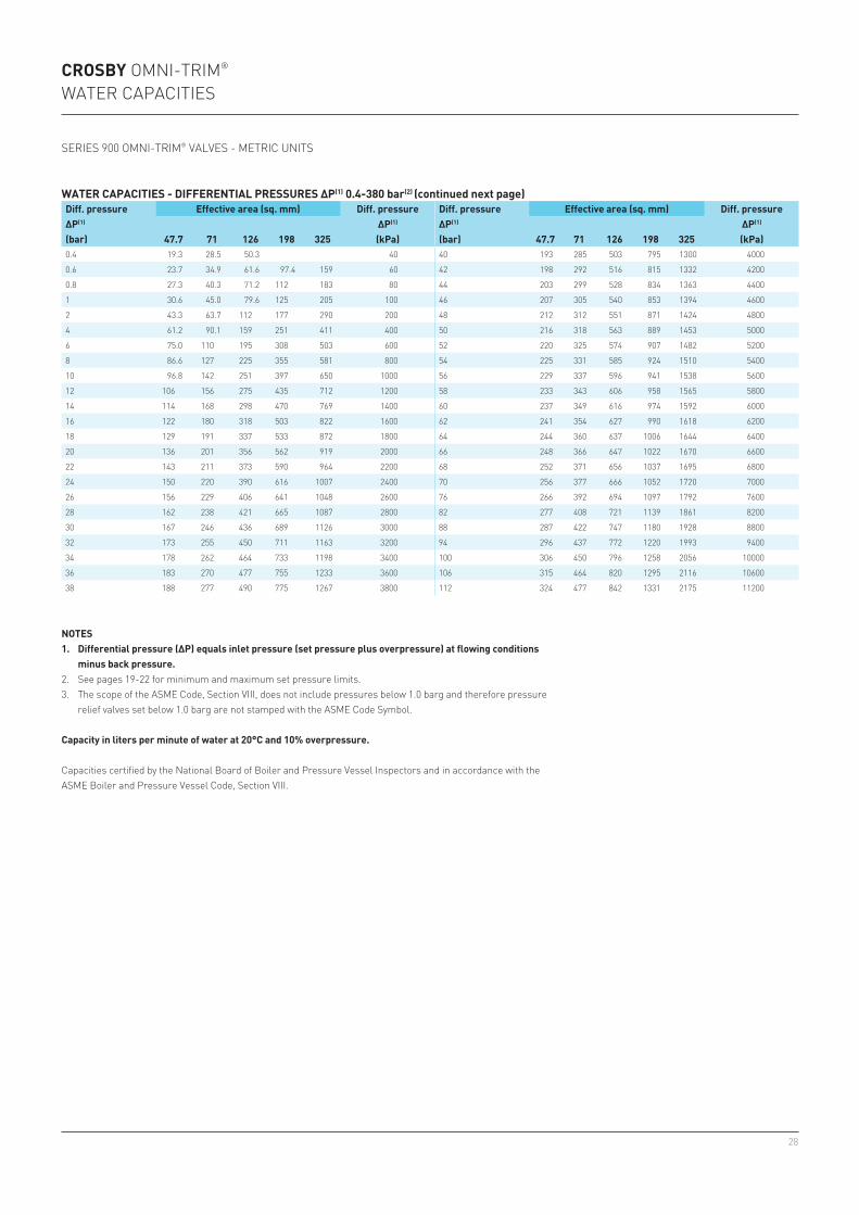
CROSBY OMNI-TRIM® WATER CAPACITIES
SERIES 900 OMNI-TRIM® VALVES - METRIC UNITS
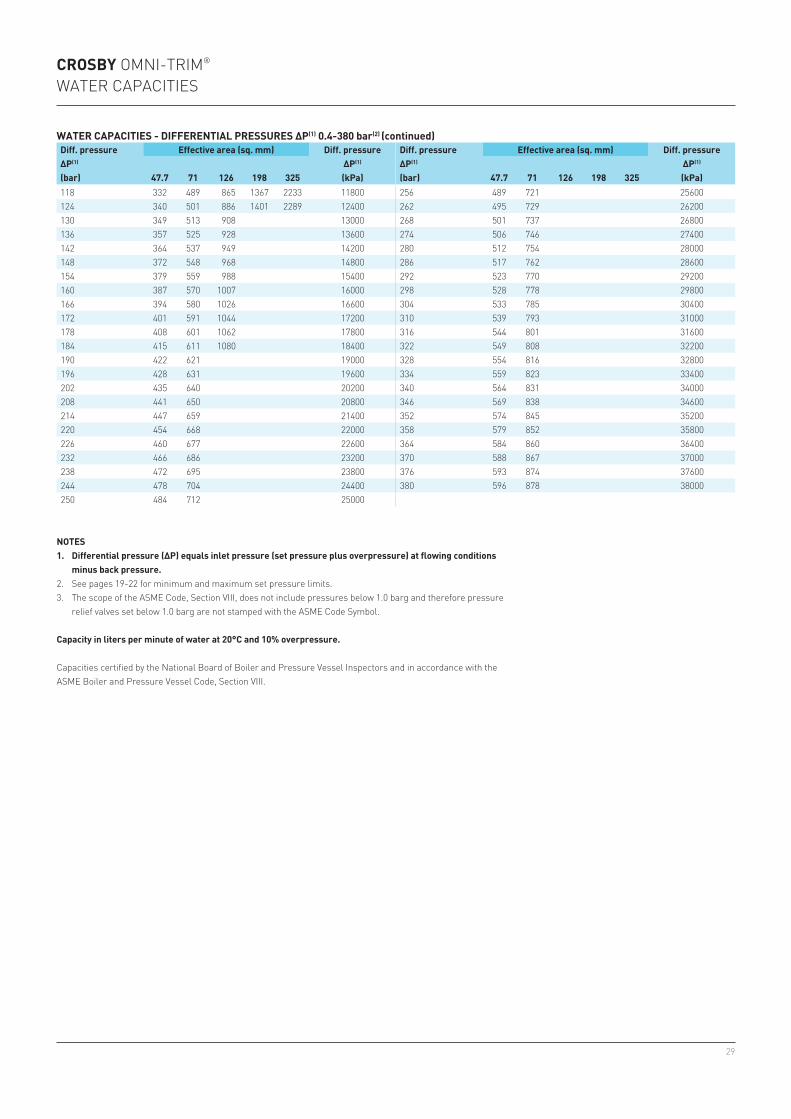
WATER CAPACITIES - DIFFERENTIAL PRESSURES ΔP(1) 0.4-380 bar(2) (continued next page)Diff. pressure Effective area (sq. mm) Diff. pressure Diff. pressure Effective area (sq. mm) Diff. pressureΔP(1) ΔP(1) ΔP(1) ΔP(1)
(bar) 47.7 71 126 198 325 (kPa) (bar) 47.7 71 126 198 325 (kPa)
NOTES1. Differential pressure (ΔP) equals inlet pressure (set pressure plus overpressure) at flowing conditions
minus back pressure.2. See pages 19-22 for minimum and maximum set pressure limits.3. The scope of the ASME Code, Section VIII, does not include pressures below 1.0 barg and therefore pressure
relief valves set below 1.0 barg are not stamped with the ASME Code Symbol.
Capacity in liters per minute of water at 20°C and 10% overpressure.
Capacities certified by the National Board of Boiler and Pressure Vessel Inspectors and in accordance with the ASME Boiler and Pressure Vessel Code, Section VIII.
29
118 332 489 865 1367 2233 11800 256 489 721 25600124 340 501 886 1401 2289 12400 262 495 729 26200130 349 513 908 13000 268 501 737 26800136 357 525 928 13600 274 506 746 27400142 364 537 949 14200 280 512 754 28000148 372 548 968 14800 286 517 762 28600154 379 559 988 15400 292 523 770 29200160 387 570 1007 16000 298 528 778 29800166 394 580 1026 16600 304 533 785 30400172 401 591 1044 17200 310 539 793 31000178 408 601 1062 17800 316 544 801 31600184 415 611 1080 18400 322 549 808 32200190 422 621 19000 328 554 816 32800196 428 631 19600 334 559 823 33400202 435 640 20200 340 564 831 34000208 441 650 20800 346 569 838 34600214 447 659 21400 352 574 845 35200220 454 668 22000 358 579 852 35800226 460 677 22600 364 584 860 36400232 466 686 23200 370 588 867 37000238 472 695 23800 376 593 874 37600244 478 704 24400 380 596 878 38000250 484 712 25000
CROSBY OMNI-TRIM® WATER CAPACITIES
WATER CAPACITIES - DIFFERENTIAL PRESSURES ΔP(1) 0.4-380 bar(2) (continued)Diff. pressure Effective area (sq. mm) Diff. pressure Diff. pressure Effective area (sq. mm) Diff. pressureΔP(1) ΔP(1) ΔP(1) ΔP(1)
(bar) 47.7 71 126 198 325 (kPa) (bar) 47.7 71 126 198 325 (kPa)
NOTES1. Differential pressure (ΔP) equals inlet pressure (set pressure plus overpressure) at flowing conditions
minus back pressure.2. See pages 19-22 for minimum and maximum set pressure limits.3. The scope of the ASME Code, Section VIII, does not include pressures below 1.0 barg and therefore pressure
relief valves set below 1.0 barg are not stamped with the ASME Code Symbol.
Capacity in liters per minute of water at 20°C and 10% overpressure.
Capacities certified by the National Board of Boiler and Pressure Vessel Inspectors and in accordance with the ASME Boiler and Pressure Vessel Code, Section VIII.
30
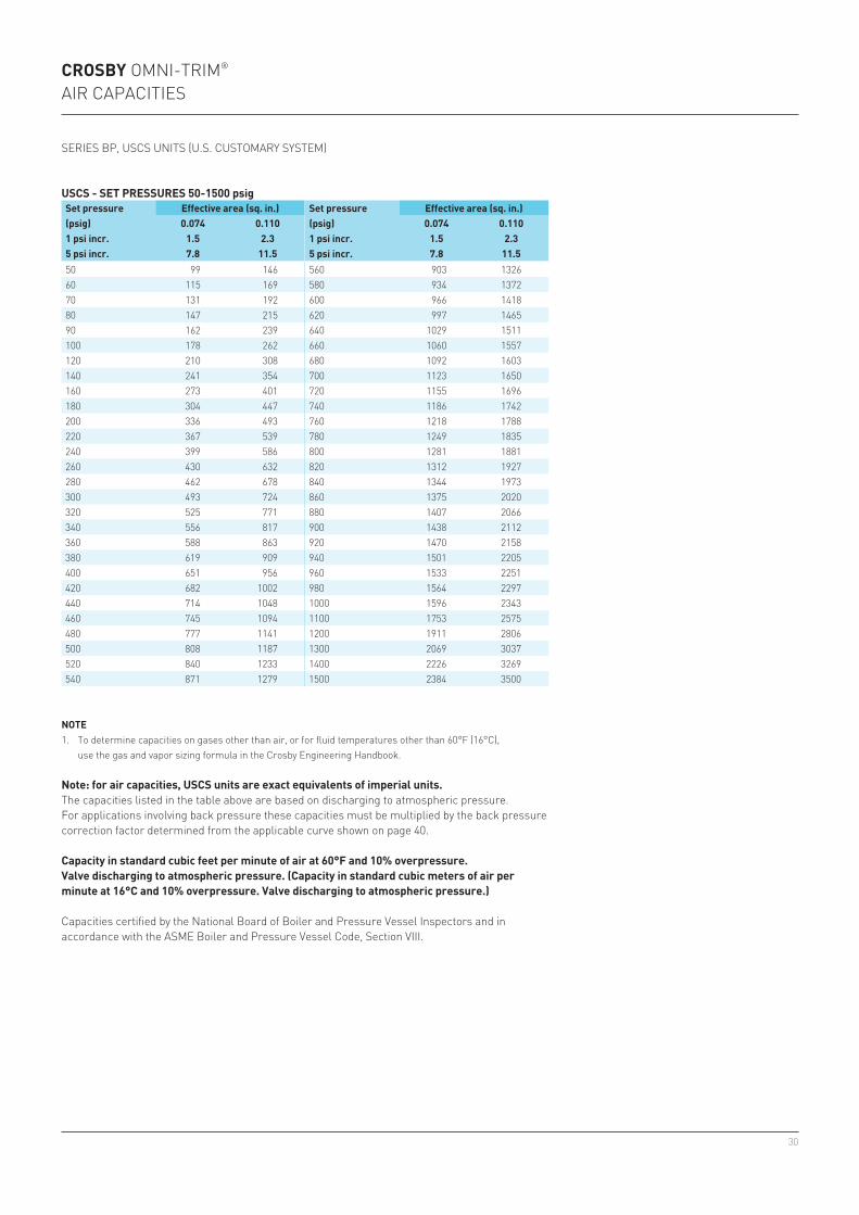
50 99 146 560 903 132660 115 169 580 934 137270 131 192 600 966 141880 147 215 620 997 146590 162 239 640 1029 1511100 178 262 660 1060 1557120 210 308 680 1092 1603140 241 354 700 1123 1650160 273 401 720 1155 1696180 304 447 740 1186 1742200 336 493 760 1218 1788220 367 539 780 1249 1835240 399 586 800 1281 1881260 430 632 820 1312 1927280 462 678 840 1344 1973300 493 724 860 1375 2020320 525 771 880 1407 2066340 556 817 900 1438 2112360 588 863 920 1470 2158380 619 909 940 1501 2205400 651 956 960 1533 2251420 682 1002 980 1564 2297440 714 1048 1000 1596 2343460 745 1094 1100 1753 2575480 777 1141 1200 1911 2806500 808 1187 1300 2069 3037520 840 1233 1400 2226 3269540 871 1279 1500 2384 3500
CROSBY OMNI-TRIM® AIR CAPACITIES
SERIES BP, USCS UNITS (U.S. CUSTOMARY SYSTEM)
Note: for air capacities, USCS units are exact equivalents of imperial units.The capacities listed in the table above are based on discharging to atmospheric pressure. For applications involving back pressure these capacities must be multiplied by the back pressure correction factor determined from the applicable curve shown on page 40.
Capacity in standard cubic feet per minute of air at 60°F and 10% overpressure. Valve discharging to atmospheric pressure. (Capacity in standard cubic meters of air per minute at 16°C and 10% overpressure. Valve discharging to atmospheric pressure.)
Capacities certified by the National Board of Boiler and Pressure Vessel Inspectors and in accordance with the ASME Boiler and Pressure Vessel Code, Section VIII.
NOTE1. To determine capacities on gases other than air, or for fluid temperatures other than 60°F (16°C),
use the gas and vapor sizing formula in the Crosby Engineering Handbook.
USCS - SET PRESSURES 50-1500 psigSet pressure Effective area (sq. in.) Set pressure Effective area (sq. in.)(psig) 0.074 0.110 (psig) 0.074 0.1101 psi incr. 1.5 2.3 1 psi incr. 1.5 2.35 psi incr. 7.8 11.5 5 psi incr. 7.8 11.5
31
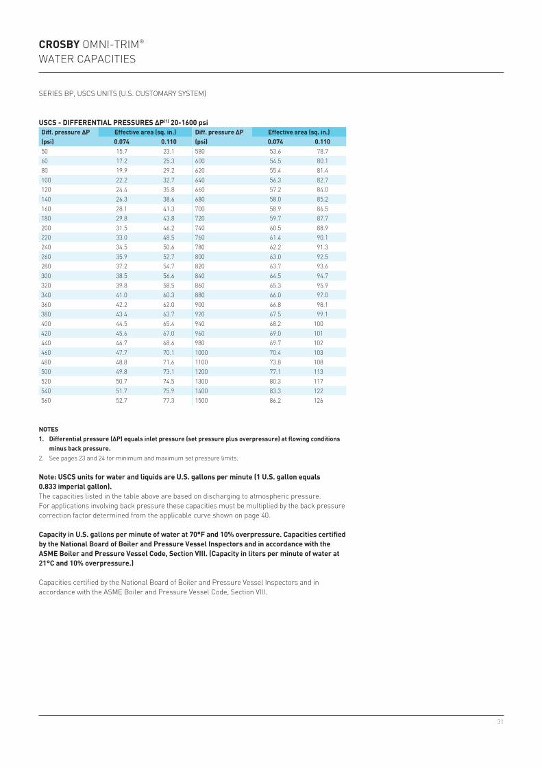
50 15.7 23.1 580 53.6 78.760 17.2 25.3 600 54.5 80.180 19.9 29.2 620 55.4 81.4100 22.2 32.7 640 56.3 82.7120 24.4 35.8 660 57.2 84.0140 26.3 38.6 680 58.0 85.2160 28.1 41.3 700 58.9 86.5180 29.8 43.8 720 59.7 87.7200 31.5 46.2 740 60.5 88.9220 33.0 48.5 760 61.4 90.1240 34.5 50.6 780 62.2 91.3260 35.9 52.7 800 63.0 92.5280 37.2 54.7 820 63.7 93.6300 38.5 56.6 840 64.5 94.7320 39.8 58.5 860 65.3 95.9340 41.0 60.3 880 66.0 97.0360 42.2 62.0 900 66.8 98.1380 43.4 63.7 920 67.5 99.1400 44.5 65.4 940 68.2 100420 45.6 67.0 960 69.0 101440 46.7 68.6 980 69.7 102460 47.7 70.1 1000 70.4 103480 48.8 71.6 1100 73.8 108500 49.8 73.1 1200 77.1 113520 50.7 74.5 1300 80.3 117540 51.7 75.9 1400 83.3 122560 52.7 77.3 1500 86.2 126
CROSBY OMNI-TRIM® WATER CAPACITIES
SERIES BP, USCS UNITS (U.S. CUSTOMARY SYSTEM)
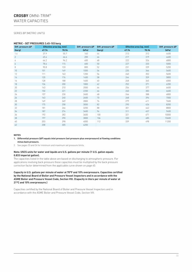
Note: USCS units for water and liquids are U.S. gallons per minute (1 U.S. gallon equals 0.833 imperial gallon).The capacities listed in the table above are based on discharging to atmospheric pressure. For applications involving back pressure these capacities must be multiplied by the back pressure correction factor determined from the applicable curve shown on page 40.
Capacity in U.S. gallons per minute of water at 70°F and 10% overpressure. Capacities certified by the National Board of Boiler and Pressure Vessel Inspectors and in accordance with the ASME Boiler and Pressure Vessel Code, Section VIII. (Capacity in liters per minute of water at 21°C and 10% overpressure.)
Capacities certified by the National Board of Boiler and Pressure Vessel Inspectors and in accordance with the ASME Boiler and Pressure Vessel Code, Section VIII.
NOTES1. Differential pressure (ΔP) equals inlet pressure (set pressure plus overpressure) at flowing conditions
minus back pressure.2. See pages 23 and 24 for minimum and maximum set pressure limits.
USCS - DIFFERENTIAL PRESSURES ΔP(1) 20-1600 psiDiff. pressure ΔP Effective area (sq. in.) Diff. pressure ΔP Effective area (sq. in.)(psi) 0.074 0.110 (psi) 0.074 0.110
32
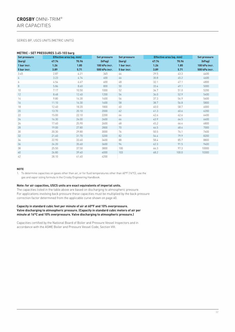
3.45 2.87 4.21 345 44 29.5 43.3 44004 3.23 4.74 400 46 30.8 45.2 46006 4.54 6.67 600 48 32.1 47.1 48008 5.86 8.60 800 50 33.4 49.1 500010 7.17 10.50 1000 52 34.7 51.0 520012 8.48 12.40 1200 54 36.0 52.9 540014 9.80 14.30 1400 56 37.3 54.9 560016 11.10 16.30 1600 58 38.7 56.8 580018 12.40 18.20 1800 60 40.0 58.7 600020 13.70 20.10 2000 62 41.3 60.6 620022 15.00 22.10 2200 64 42.6 62.6 640024 16.30 24.00 2400 66 43.9 64.5 660026 17.60 25.90 2600 68 45.2 66.4 680028 19.00 27.80 2800 70 46.5 68.4 700030 20.30 29.80 3000 76 50.5 74.1 760032 21.60 31.70 3200 82 54.4 79.9 820034 22.90 33.60 3400 88 58.4 85.7 880036 24.20 35.60 3600 94 62.3 91.5 940038 25.50 37.50 3800 100 66.3 97.3 1000040 26.80 39.40 4000 103 68.2 100.0 1030042 28.10 41.40 4200
CROSBY OMNI-TRIM® AIR CAPACITIES
SERIES BP, USCS UNITS (METRIC UNITS)
Note: for air capacities, USCS units are exact equivalents of imperial units.The capacities listed in the table above are based on discharging to atmospheric pressure. For applications involving back pressure these capacities must be multiplied by the back pressure correction factor determined from the applicable curve shown on page 40.
Capacity in standard cubic feet per minute of air at 60°F and 10% overpressure. Valve discharging to atmospheric pressure. (Capacity in standard cubic meters of air per minute at 16°C and 10% overpressure. Valve discharging to atmospheric pressure.)
Capacities certified by the National Board of Boiler and Pressure Vessel Inspectors and in accordance with the ASME Boiler and Pressure Vessel Code, Section VIII.
NOTE1. To determine capacities on gases other than air, or for fluid temperatures other than 60°F (16°C), use the
gas and vapor sizing formula in the Crosby Engineering Handbook.
METRIC - SET PRESSURES 3.45-103 bargSet pressure Effective area (sq. mm) Set pressure Set pressure Effective area (sq. mm) Set pressure(barg) 47.74 70.96 (kPag) (barg) 47.74 70.96 (kPag)1 bar incr. 1.26 1.85 100 kPa incr. 1 bar incr. 1.26 1.85 100 kPa incr.5 bar incr. 3.89 5.71 500 kPa incr. 5 bar incr. 3.89 5.71 500 kPa incr.
33
1.4 37.9 55.7 140 44 213 312 44002 45.4 66.6 200 46 217 319 46004 64.2 94.2 400 48 222 326 48006 78.6 115 600 50 227 333 50008 90.8 133 800 52 231 339 520010 101 149 1000 54 235 346 540012 111 163 1200 56 240 352 560014 120 176 1400 58 244 359 580016 128 188 1600 60 248 365 600018 136 200 1800 62 252 371 620020 143 210 2000 64 256 377 640022 150 221 2200 66 260 383 660024 157 230 2400 68 264 388 680026 163 240 2600 70 268 394 700028 169 249 2800 76 279 411 760030 175 258 3000 82 290 426 820032 181 266 3200 88 301 442 880034 187 274 3400 94 311 457 940036 192 282 3600 100 321 471 1000038 197 290 3800 106 330 485 1060040 203 298 4000 112 339 498 1120042 208 305 4200
CROSBY OMNI-TRIM® WATER CAPACITIES
SERIES BP (METRIC UNITS)
Note: USCS units for water and liquids are U.S. gallons per minute (1 U.S. gallon equals 0.833 imperial gallon).The capacities listed in the table above are based on discharging to atmospheric pressure. For applications involving back pressure these capacities must be multiplied by the back pressure correction factor determined from the applicable curve shown on page 40.
Capacity in U.S. gallons per minute of water at 70°F and 10% overpressure. Capacities certified by the National Board of Boiler and Pressure Vessel Inspectors and in accordance with the ASME Boiler and Pressure Vessel Code, Section VIII. (Capacity in liters per minute of water at 21°C and 10% overpressure.)
Capacities certified by the National Board of Boiler and Pressure Vessel Inspectors and in accordance with the ASME Boiler and Pressure Vessel Code, Section VIII.
NOTES1. Differential pressure (ΔP) equals inlet pressure (set pressure plus overpressure) at flowing conditions
minus back pressure.2. See pages 23 and 24 for minimum and maximum set pressure limits.
METRIC - SET PRESSURES 3.45-103 bargDiff. pressure ΔP Effective area (sq. mm) Diff. pressure ΔP Diff. pressure ΔP Effective area (sq. mm) Diff. pressure ΔP(barg) 47.74 70.96 (kPa) (barg) 47.74 70.96 (kPa)
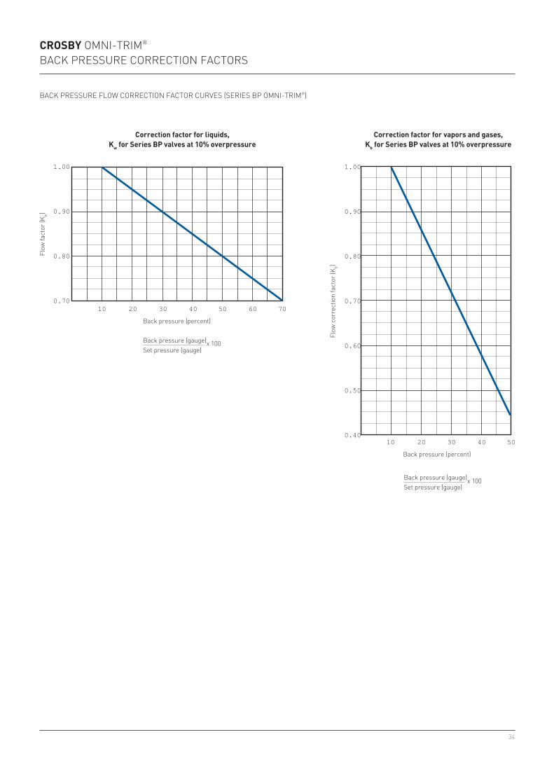
34
10 20 30 40 50
1.00
0.90
0.80
0.70
0.60
0.50
0.40
Back Pressure (gage)Set Pressure (gage)
x 100
Back Pressure - Percent
Flow Correction Factor, Kb
Flow Factor, Kw
1.00
0.90
0.80
0.7010 20 30 40 50 60 70
Back Pressure (gage)Set Pressure (gage)
x 100
Back Pressure - Percent
CROSBY OMNI-TRIM® BACK PRESSURE CORRECTION FACTORS
Correction factor for vapors and gases, Kb for Series BP valves at 10% overpressure
Correction factor for liquids, Kw for Series BP valves at 10% overpressure
BACK PRESSURE FLOW CORRECTION FACTOR CURVES (SERIES BP OMNI-TRIM®)
Flow
fact
or (K
w)
Back pressure (percent)
Back pressure (percent)
Flow
cor
rect
ion
fact
or (K
b)Back pressure (gauge)Set pressure (gauge)
x 100
Back pressure (gauge)Set pressure (gauge)
x 100
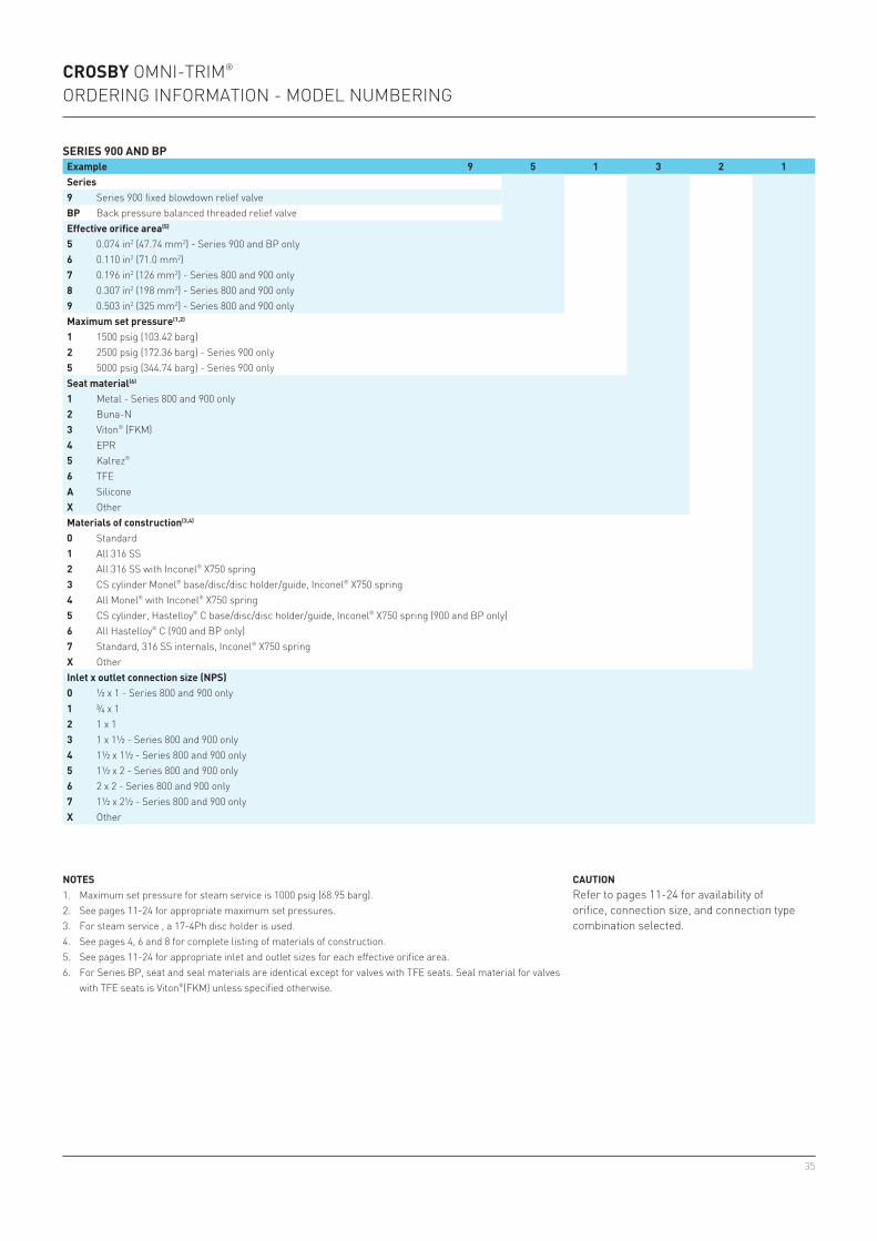
35
CROSBY OMNI-TRIM® ORDERING INFORMATION - MODEL NUMBERING
CAUTIONRefer to pages 11-24 for availability of orifice, connection size, and connection type combination selected.
SERIES 900 AND BPExample 9 5 1 3 2 1Series9 Series 900 fixed blowdown relief valveBP Back pressure balanced threaded relief valveEffective orifice area(5)
5 0.074 in2 (47.74 mm2) - Series 900 and BP only6 0.110 in2 (71.0 mm2)7 0.196 in2 (126 mm2) - Series 800 and 900 only8 0.307 in2 (198 mm2) - Series 800 and 900 only9 0.503 in2 (325 mm2) - Series 800 and 900 onlyMaximum set pressure(1,2)
1 1500 psig (103.42 barg)2 2500 psig (172.36 barg) - Series 900 only5 5000 psig (344.74 barg) - Series 900 onlySeat material(6)
1 Metal - Series 800 and 900 only2 Buna-N3 Viton® (FKM)4 EPR5 Kalrez®
6 TFEA SiliconeX OtherMaterials of construction(3,4)
0 Standard1 All 316 SS2 All 316 SS with Inconel® X750 spring3 CS cylinder Monel® base/disc/disc holder/guide, Inconel® X750 spring4 All Monel® with Inconel® X750 spring5 CS cylinder, Hastelloy® C base/disc/disc holder/guide, Inconel® X750 spring (900 and BP only)6 All Hastelloy® C (900 and BP only)7 Standard, 316 SS internals, Inconel® X750 springX OtherInlet x outlet connection size (NPS)0 ½ x 1 - Series 800 and 900 only1 ¾ x 12 1 x 13 1 x 1½ - Series 800 and 900 only4 1½ x 1½ - Series 800 and 900 only5 1½ x 2 - Series 800 and 900 only6 2 x 2 - Series 800 and 900 only7 1½ x 2½ - Series 800 and 900 onlyX Other
NOTES1. Maximum set pressure for steam service is 1000 psig (68.95 barg).2. See pages 11-24 for appropriate maximum set pressures.3. For steam service , a 17-4Ph disc holder is used.4. See pages 4, 6 and 8 for complete listing of materials of construction.5. See pages 11-24 for appropriate inlet and outlet sizes for each effective orifice area.6. For Series BP, seat and seal materials are identical except for valves with TFE seats. Seal material for valves
with TFE seats is Viton®(FKM) unless specified otherwise.
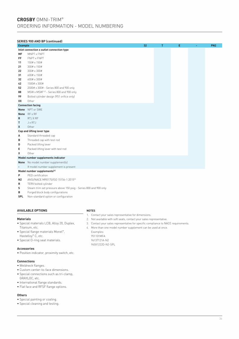
36
CROSBY OMNI-TRIM® ORDERING INFORMATION - MODEL NUMBERING
SERIES 900 AND BP (continued)Example 32 T E - PN2Inlet connection x outlet connection typeMF MNPT x FNPTFF FNPT x FNPT11 150# x 150#21 300# x 150#22 300# x 300#31 600# x 150#32 600# x 300#42 1500# x 300#52 2500# x 300# - Series 800 and 900 only88 MSW x MSW[1,2] - Series 800 and 900 only99 Bolted cylinder design (951 orifice only)XX OtherConnection facingNone NPT or SWENone RF x RFR RTJ X RFT J x RTJX OtherCap and lifting lever typeA Standard threaded capB Threaded cap with test rodD Packed lifting leverE Packed lifting lever with test rodX OtherModel number supplements indicatorNone No model number supplement(s)- If model number supplement is presentModel number supplements[4]
P PED certificationN2 ANSI/NACE MR0175/ISO 15156-1:2015[3]
R TERV bolted cylinderS Steam trim set pressure above 150 psig - Series 800 and 900 onlyB Forged block body configurationsSPL Non-standard option or configuration
AVAILABLE OPTIONS
Materials• Special materials LCB, Alloy 20, Duplex,
Titanium, etc.• Special flange materials Monel®,
Hastelloy® C, etc.• Special O-ring seat materials.
Accessories• Position indicator, proximity switch, etc.
Connections• Weldneck flanges.• Custom center-to-face dimensions.• Special connections such as tri-clamp,
GRAYLOC, etc.• International flange standards.• Flat face and RFSF flange options.
Others• Special painting or coating.• Special cleaning and testing.
NOTES1. Contact your sales representative for dimensions.2. Not available with soft seats, contact your sales representative.3. Contact your sales representative for specific compliance to NACE requirements.4. More than one model number supplement can be used at once. Examples: 951101MFA 96137121A-N2 965X1222D-N2-SPL
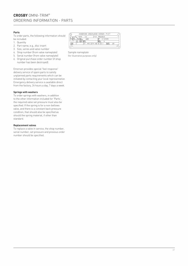
37
CROSBY OMNI-TRIM®
ORDERING INFORMATION - PARTS
PartsTo order parts, the following information should be included:1. Quantity2. Part name, e.g., disc insert3. Size, series and valve number4. Shop number (from valve nameplate)5. Serial number (from valve nameplate)6. Original purchase order number (if shop
number has been destroyed).
Emerson provides special 'fast response' delivery service of spare parts to satisfy unplanned parts requirements which can be initiated by contacting your local representative. Emergency delivery service is available direct from the factory, 24 hours a day, 7 days a week.
Springs with washersTo order springs with washers, in addition to the other information included for 'Parts', the required valve set pressure must also be specified. If the spring is for a non-bellows valve, and there is a constant back pressure condition, that should also be specified as should the spring material, if other than standard.
Replacement valvesTo replace a valve in service, the shop number, serial number, set pressure and previous order number should be specified.
Sample nameplate(for illustrative purposes only)
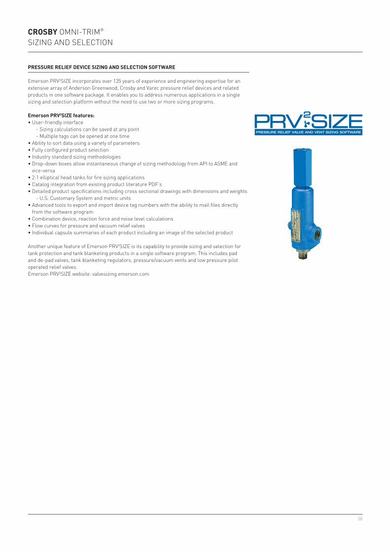
38
CROSBY OMNI-TRIM®
SIZING AND SELECTION
PRESSURE RELIEF DEVICE SIZING AND SELECTION SOFTWARE
Emerson PRV2SIZE incorporates over 135 years of experience and engineering expertise for an extensive array of Anderson Greenwood, Crosby and Varec pressure relief devices and related products in one software package. It enables you to address numerous applications in a single sizing and selection platform without the need to use two or more sizing programs.
Emerson PRV2SIZE features:• User-friendly interface - Sizing calculations can be saved at any point - Multiple tags can be opened at one time• Ability to sort data using a variety of parameters• Fully configured product selection• Industry standard sizing methodologies• Drop-down boxes allow instantaneous change of sizing methodology from API to ASME and
vice-versa• 2:1 elliptical head tanks for fire sizing applications• Catalog integration from existing product literature PDF’s• Detailed product specifications including cross sectional drawings with dimensions and weights - U.S. Customary System and metric units• Advanced tools to export and import device tag numbers with the ability to mail files directly
from the software program• Combination device, reaction force and noise level calculations• Flow curves for pressure and vacuum relief valves• Individual capsule summaries of each product including an image of the selected product
Another unique feature of Emerson PRV2SIZE is its capability to provide sizing and selection for tank protection and tank blanketing products in a single software program. This includes pad and de-pad valves, tank blanketing regulators, pressure/vacuum vents and low pressure pilot operated relief valves.Emerson PRV2SIZE website: valvesizing.emerson.com

39
CROSBY OMNI-TRIM®
DIRECT SPRING PRESSURE RELIEF VALVES

40
Neither Emerson, Emerson Automation Solutions, nor any of their affiliated entities assumes responsibility for the selection, use or maintenance of any product. Responsibility for proper selection, use, and maintenance of any product remains solely with the purchaser and end user.
Crosby is a mark owned by one of the companies in the Emerson Automation Solutions business unit of Emerson Electric Co. Emerson Automation Solutions, Emerson and the Emerson logo are trademarks and service marks of Emerson Electric Co. All other marks are the property of their respective owners.
The contents of this publication are presented for informational purposes only, and while every effort has been made to ensure their accuracy, they are not to be construed as warranties or guarantees, express or implied, regarding the products or services described herein or their use or applicability. All sales are governed by our terms and conditions, which are available upon request. We reserve the right to modify or improve the designs or specifications of such products at any time without notice.
Emerson.com/FinalControl