crosby lifting clamps - commercial group inc. · crosby ® lifting clamps copyright © 2016 the...
TRANSCRIPT

CROSBY®
LIFTING
CLAMPS
Crosby® Lifting Clamps
410
CR
OS
BY
® L
IFT
ING
CL
AM
PS
Copyright © 2016 The Crosby Group LLC All Rights Reserved
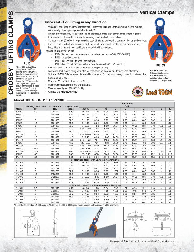
IPU10S: For use with Stainless Steel material.IPU10H: For use with materials with a surface hardness to 47Rc (450 HB).
Universal - For Lifting in any Direction
• Available in capacities of .5 thru 30 metric tons (Higher Working Load Limits are available upon request).
• Wide variety of jaw openings available: 0” to 6.13”.
• Welded alloy steel body for strength and smaller size. Forged alloy components, where required.
•
• Company name (CrosbyIP), logo, Working Load Limit and jaw opening permanently stamped on body.
• Each product is individually serialized, with the serial number and Proof Load test date stamped on
Available in a variety of styles:
• IP10 - Standard clamp for materials with a surface hardness to 363HV10 (345 HB).
• IP10J - Larger jaw opening.
• IP10S - For use with Stainless Steel material.
• IP10H - For use with materials with a surface hardness to 472HV10 (450 HB).
• Full 180° turning range for material transfer, turning or moving.
• Lock open, lock closed ability with latch for pretension on material and then release of material.
• Optional IP-5000 Stinger assembly available (see page 428). Allows for easy connection between the
clamp and hoist hook.
• Minimum WLL of 10% of Maximum WLL.
• Maintenance replacement kits are available.
• Manufactured by an ISO 9001 facility.
• All sizes are RFID EQUIPPED.
The IPU10 vertical lifting clamp is used for lifting, turning, moving or vertical transfer of sheet, plates, or fabrications from horizontal to vertical and down to horizontal (180°) as needed. The hinged hoisting eye allows for the clamp to place and lift the load from any direction, or with a multiple leg sling without side-loading the clamp.
IPU10SIPU10
ModelWorking Load Limit
(t)*IPU10 Stock
No.Weight Each
(lbs.)
Dimensions (in.)
Jaw A B C D E F G H J K
IPU10 0.5 2701675 4.19 0 - .63 1.73 5.04 8.98 1.57 4.53 1.61 1.10 - .43
IPU10 1 2701663 5.29 0 - .75 1.77 5.47 8.74 1.57 4.96 1.61 1.50 - .43
IPU10 2 2701677 18.7 0 - 1.38 3.07 7.91 14.65 2.76 7.48 2.40 2.17 - .63
IPU10 3 2701665 32.6 0 - 1.56 3.94 9.96 17.52 2.95 8.86 3.07 2.36 - .79
IPU10 4.5 2701667 35.3 0 - 1.56 3.94 9.96 17.52 2.95 9.13 3.23 2.56 - .79
IPU10 6 2701669 53.0 0 - 2.00 4.96 11.89 20.67 3.15 11.50 3.31 3.74 1.73 .79
IPU1J 6 2702469 67.3 2.00 - 4.00 4.96 11.89 20.67 3.15 13.46 3.31 3.74 1.73 .79
IPU10 9 2701671 65.0 0 - 2.00 4.96 12.80 21.93 3.15 12.20 3.62 4.13 1.73 .79
IPU10J 9 2701673 67.2 2.00 - 4.00 4.96 12.80 22.13 3.15 14.17 3.62 4.13 1.73 .79
IPU10 12 2701679 126 0 - 2.13 6.30 15.39 24.53 3.15 13.03 4.61 5.39 1.61 .98
IPU10J 12 2701681 130 2.13 - 4.25 7.01 17.28 26.50 3.15 16.34 4.61 5.39 1.61 .98
IPU10 16 2701683 159 .25 - 2.50 7.01 18.31 28.90 3.46 15.63 4.69 6.02 1.77 .98
IPU10J 16 2701685 187 2.50 - 5.00 8.19 20.51 31.10 3.46 18.58 4.69 6.34 1.77 .98
IPU10 22.5 2701687 280 .25 - 3.13 8.74 21.81 33.66 4.33 18.50 5.35 7.32 1.93 .98
IPU10J 22.5 2701689 287 3.13 - 6.13 9.96 24.72 36.61 4.33 22.64 5.35 7.72 1.93 .98
IPU10 30 2701691 337 .25 - 3.13 8.74 21.46 33.86 4.33 18.50 5.98 7.32 2.13 1.18
IPU10J 30 2701693 364 3.13 - 6.13 9.84 24.41 36.81 4.33 22.24 5.98 7.72 2.13 1.18
For stainless steel - with universal hoisting eye
IPU10S 0.5 2702275 4.19 0 - .63 1.73 5.04 8.98 1.57 4.53 1.61 1.10 - .43
IPU10S 1 2702263 4.63 0 - .75 1.77 5.47 8.74 1.57 4.96 1.61 1.50 - .43
IPU10S 2 2702277 16.8 0 - 1.38 3.07 7.91 14.65 2.76 7.48 2.40 2.17 - .63
IPU10S 3 2702265 32.7 0 - 1.56 3.94 9.96 1.752 2.95 8.86 3.07 2.36 - .79
IPU10S 4.5 2702267 35.3 0 - 1.56 3.94 9.96 17.52 2.95 9.13 3.23 2.56 - .79
IPU10S 6 2702269 53.0 0 - 2.00 4.96 11.89 20.67 3.15 11.50 3.31 3.74 1.73 .79
IPU10S 9 2702271 65.1 0 - 2.00 4.96 12.80 21.93 3.15 12.20 3.62 4.13 1.73 .79
IPU10S 12 2702279 67.3 0 - 2.13 6.30 15.39 24.53 3.15 13.03 4.61 5.39 1.61 .98
For very hard materials - with universal hoisting eye
IPU10H 0.5 2702175 4.19 0 - .63 1.73 5.04 8.98 1.57 4.53 1.61 1.10 - .43
IPU10H 1 2702177 16.8 0 - 1.38 3.07 7.91 14.65 2.76 7.48 2.40 2.17 - .63
IPU10H 2 2702165 32.7 0 - 1.56 3.94 9.96 17.52 2.95 8.86 3.07 2.36 - .79
IPU10H 3 2702167 35.3 0 - 1.56 3.94 9.96 17.52 2.95 9.13 3.23 2.56 - .79
IPU10H 4.5 2702169 53.0 0 - 2.00 4.96 11.89 20.67 3.15 11.50 3.31 3.74 1.73 .79
IPU10H 6 2702171 65.1 0 - 2.00 4.96 12.80 21.93 3.15 12.20 3.62 4.13 1.73 .79
K
J
G
* Design Factor based on EN 13155 and ASME B30.20. Model IPU10R (remote control opening and closing via a cable) on request.
Vertical Clamps
Model IPU10 / IPU10S / IPU10H
411
CR
OS
BY
® L
IFT
ING
CL
AM
PS
Copyright © 2016 The Crosby Group LLC All Rights Reserved
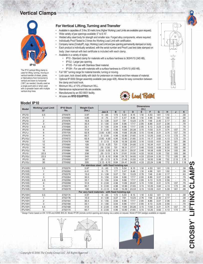
For Vertical Lifting, Turning and Transfer• Available in capacities of .5 thru 30 metric tons (Higher Working Load Limits are available upon request).
• Wide variety of jaw openings available: 0” to 6.10”.
• Welded alloy steel body for strength and smaller size. Forged alloy components, where required.
•
• Company name (CrosbyIP), logo, Working Load Limit and jaw opening permanently stamped on body.
• Each product is individually serialized, with the serial number and Proof Load test date stamped on
body.
• Available in a variety of styles:
• IP10 - Standard clamp for materials with a surface hardness to 363HV10 (345 HB).
• IP10J - Larger jaw opening.
• IP10S - For use with Stainless Steel material.
• IP10H - For use with materials with a surface hardness to 472HV10 (450 HB).
• Full 180° turning range for material transfer, turning or moving.
• Lock open, lock closed ability with latch for pretension on material and then release of material.
• Optional IP-5000 Stinger assembly available (see page 428). Allows for easy connection between
the clamp and hoist hook.
• Minimum WLL of 10% of Maximum WLL.
• Maintenance replacement kits are available.
• Manufactured by an ISO 9001 facility.
• All sizes are RFID EQUIPPED.
The IP10 vertical lifting clamp is used for lifting, turning, moving or vertical transfer of sheet, plates, or fabrications from horizontal to vertical and down to horizontal (180°) as needed. Usually used as a single point pick or when used with a spreader beam with multiple vertical drop lines.
IP10
Model IP10
ModelWorking Load Limit
(t)*IP10 Stock
No.Weight Each
(lbs.)
Dimensions (in.)
Jaw A B C D E F G H J K
IPU10 0.5 2701674 3.97 0 - .63 1.73 5.04 8.15 1.18 4.53 1.61 1.10 - .39
IPU10 1 2701662 4.85 0 - .75 1.77 5.47 8.46 1.18 4.96 1.61 1.50 - .39
IPU10 2 2701676 16.8 0 - 1.38 3.07 7.91 13.23 2.76 7.48 2.40 2.17 - .63
IPU10 3 2701664 30.4 0 - 1.56 3.94 9.96 17.17 2.95 8.86 3.07 2.36 - .79
IPU10 4.5 2701666 33.1 0 - 1.56 3.94 9.96 17.17 2.95 9.13 3.23 2.56 - .79
IPU10 6 2701668 51.9 0 - 2.00 4.96 11.89 20.28 3.15 11.50 3.31 3.74 1.57 .79
IPU1J 6 2701705 62.9 2.00 - 4.00 4.96 11.89 20.28 3.15 13.46 3.31 3.74 1.57 .79
IPU10 9 2701670 60.7 0 - 2.00 4.96 12.80 21.65 3.15 12.20 3.62 4.13 1.73 .79
IPU10J 9 2701672 62.9 2.00 - 4.00 4.96 12.80 21.85 3.15 14.17 3.62 4.13 1.73 .79
IPU10 12 2701678 108 0 - 2.13 6.30 15.39 22.83 3.16 13.03 4.61 5.39 1.61 .98
IPU10J 12 2701680 128 2.13 - 4.25 7.01 17.28 24.80 3.15 16.34 4.61 5.39 1.61 .98
IPU10 16 2701682 150 .25 - 2.50 7.01 18.31 27.17 3.46 15.63 4.69 6.02 1.93 .98
IPU10J 16 2701684 199 2.50 - 5.00 8.19 20.51 29.37 3.46 18.58 4.69 6.34 1.93 .98
IPU10 22.5 2701686 238 .25 - 3.13 8.74 21.81 31.50 4.33 18.50 5.35 7.32 1.93 .98
IPU10J 22.5 2701688 243 3.13 - 6.10 9.96 24.72 34.65 4.33 22.64 5.35 7.72 1.93 .98
IPU10 30 2701690 327 .25 - 3.13 8.74 21.46 31.50 4.33 18.50 5.98 7.32 2.13 1.18
IPU10J 30 2701692 335 3.13 - 6.10 9.84 24.41 34.65 4.33 22.24 5.98 7.72 2.13 1.18
For stainless steel - with fixed hoisting eye
IPU10S 0.5 2702274 3.97 0 - .63 1.73 5.04 8.15 1.18 4.53 1.61 1.10 - .39
IPU10S 1 2702262 4.41 0 - .75 1.77 5.47 8.46 1.18 4.96 1.61 1.50 - .39
IPU10S 2 2702276 15.0 0 - 1.38 3.07 7.91 13.23 2.76 7.48 2.40 2.17 - .63
IPU10S 3 2702264 30.5 0 - 1.56 3.94 9.96 17.17 2.95 8.86 3.07 2.36 - .79
IPU10S 4.5 2702266 33.1 0 - 1.56 3.94 9.96 17.17 2.95 9.13 3.23 2.56 - .79
IPU10S 6 2702268 51.9 0 - 2.00 4.96 11.89 20.67 3.15 11.50 3.31 3.74 1.57 .79
IPU10S 9 2702270 60.7 0 - 2.00 4.96 12.80 21.93 3.15 12.20 3.62 4.13 1.73 .98
IPU10S 12 2702278 108 0 - 2.13 6.30 15.39 24.53 3.15 13.03 4.61 5.39 1.61 .98
For very hard materials - with fixed hoisting eye
IPU10H 0.5 2702174 3.97 0 - .63 1.73 5.04 8.15 1.18 4.53 1.61 1.10 - .39
IPU10H 1 2702176 15.0 0 - 1.38 3.07 7.91 13.23 2.76 7.48 2.40 2.17 - .39
IPU10H 2 2702164 30.4 0 - 1.56 3.94 9.96 17.17 2.95 8.86 3.07 2.36 - .63
IPU10H 3 2702166 33.1 0 - 1.56 3.94 9.96 17.17 2.95 9.13 3.23 2.56 - .79
IPU10H 4.5 2702168 51.9 0 - 2.00 4.96 11.89 20.28 3.15 11.50 3.31 3.74 1.57 .79
IPU10H 6 2702170 60.7 0 - 2.00 4.96 12.80 21.65 3.15 12.20 3.62 4.13 1.73 .98
* Design Factor based on EN 13155 and ASME B30.20. Model IP10R (remote control opening and closing via a cable) on request. Model IP10W (wedge) available on request.
Vertical Clamps
412
CR
OS
BY
® L
IFT
ING
CL
AM
PS
Copyright © 2016 The Crosby Group LLC All Rights Reserved
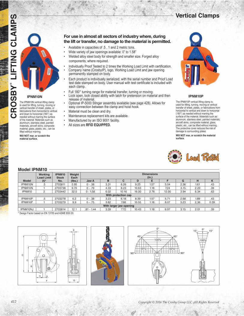
For use in almost all sectors of industry where, during the lift or transfer, no damage to the material is permitted.
• Available in capacities of .5 , 1 and 2 metric tons.
• Wide variety of jaw openings available: 0” to 1.58”
• Welded alloy steel body for strength and smaller size. Forged alloy
components, where required.
• Individually Proof Tested to 2 times the Work• Company name (CrosbyIP), logo, Working Load Limit and jaw opening permanently stamped on body.
• Each product is individually serialized, with the serial number and Proof Load tes each clamp.
• Full 180° turning range for material transfer, turning or moving.• Lock open, lock closed ability with latch for pretension on material and then release of material.• Optional IP-5000 Stinger assembly available (see page 428). Allows for easy connection between the clamp and hoist hook.
• Material must be clean and dry.
• Maintenance replacement kits are available.
• Manufactured by an ISO 9001 facility.
• All sizes are RFID EQUIPPED.
The IPNM10N vertical lifting clamp is used for lifting, turning, moving or vertical transfer of sheet, plates, or fabrications from horizontal to vertical and down to horizontal (180°) as needed without marring the surface of the material. Materials such as aluminum, stainless steel, painted materials, aircraft skins, composite material, glass, plastic, etc., can be lifted without marring.
Will NOT mar, or scratch the material surface.
The IPNM10P vertical lifting clamp is used for lifting, turning, moving or vertical transfer of sheet, plates, or fabrications from horizontal to vertical and down to horizontal (180°) as needed without marring the surface of the material. Materials such as aluminum, stainless steel, painted materials, aircraft skins, composite material, glass, plastic, etc., can be lifted without marring. The protective cover reduces the risk of damage to surrounding plates.
Will NOT mar, or scratch the material surface.
IPNM10N IPNM10P
Model
WorkingLoad Limit
(t)*
IPNM10Stock
No.
WeightEach(lbs.)
Dimensions(in.)
Jaw A B C D E F G H K
IPNM10N .5 2703811 5.95 0 - .38 3.31 6.26 9.25 1.57 5.04 2.36 1.61 .43
IPNM10N 1 2703738 9.70 0 - .79 4.33 8.23 10.63 1.18 7.24 3.15 2.20 .39
IPNM10 2 2703442 32.0 0 - 1.58 6.02 10.16 16.00 2.76 12.00 3.94 6.34 .63
With protection cap
IPNM10P .5 2703278 6.2 0 - .38 3.23 6.18 8.39 1.57 5.71 2.68 1.89 .43
IPNM10P 1 2703279 9.9 0 - .75 3.82 7.68 10.55 1.18 8.07 3.23 2.36 0.39
With larger jaw opening
IPNM10NJ 1 2703814 12.1 .81 - 1.44 3.39 7.72 10.43 1.18 6.97 3.15 2.01 .39
Model IPNM10
* Design Factor based on EN 13155 and ASME B30.20.
Vertical Clamps

413
CR
OS
BY
® L
IFT
ING
CL
AM
PS
Copyright © 2016 The Crosby Group LLC All Rights Reserved
For vertical transport of plates
• Available in capacities of 1 and 2 metric tons.
• Jaw openings available: 0 to 35mm; 0” to 1.97”.
• Welded alloy steel body for strength and smaller size. Forged alloy components
where required.
•
• Company name (CrosbyIP), logo, Working Load Limit and jaw opening
permanently stamped on body.
• Each product is individually serialized, with the serial number and Proof Load test
clamp.
• Available in a variety of styles:Full 180° turning range for material transfer, turning
or moving.
• Lock open, lock closed ability with latch for pretension on material and then
release of material.
• Optional IP-5000 Stinger assembly available (see page 428). Allows for easy
connection between the clamp and hoist hook.
• Minimum WLL of 10% of Maximum WLL.
• Maintenance replacement parts are available.
• Manufactured by an ISO 9001 facility.
• All sizes are RFID EQUIPPED.
The IPU10/A automatically clicks on to the material as soon as the clamp is placed on the plate. The fact that the safety lock remains in position as the clamp closes precludes hazardous situations.Fastening the IPU10/A clamp in places that are dif�cult to reach is no problem.
K
J
G
Model
WorkingLoad Limit
(t)*
IPU10/AStock No.
WeightEach(lbs.)
Dimensions (in.)
Jaw A B C D E F G H K
IPU10/A 1 2701628 5.07 0 - .79 1.77 5.43 9.37 1.57 5.04 1.61 1.46 0.43
IPU10/A 2 2701629 19.62 0 - 1.38 3.07 7.9 14.88 2.76 7.87 2.40 2.83 0.63
IPU10/A 6 2701638 52.91 0 - 1.97 4.96 11.89 20.67 3.14 11.50 3.31 3.74 0.79
Model IPU10/A
* Design Factor based on EN 13155 and ASME B30.20.
IPU10/A
Vertical Clamps
414
CR
OS
BY
® L
IFT
ING
CL
AM
PS
Copyright © 2016 The Crosby Group LLC All Rights Reserved
• Each product is individually serialized, with the serial number and Proof
Load test date stamped on body.
included with each clamp.• Maintenance replacement parts are available.
• Manufactured by a ISO 9001 facility.
• All sizes are RFID EQUIPPED.
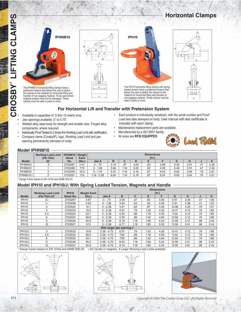
The IPHNM10 horizontal lifting clamps have a pretension feature that allows the user to attach the clamps to the material for horizontal lifting and transfer of non-sagging material. To be used where material surface must not be damaged. These clamps must be used in pairs or more.
The IPH10 horizontal lifting clamps with spring loaded tension have a pretension feature that allows the user to attach the clamps to the material for horizontal lifting and transfer of non-sagging material. These clamps must be used in pairs or more.
IPH10IPHNM10
A
B
C
D
E
G
F
Model
Working Load Limit(Per Pair)
(t)*
IPHNM10Stock
No.
WeightEach(lbs.)
Dimensions(in.)
Jaw A B C D E F G H J K
IPHNM10 .5 2703287 4.41 0 - .75 3.19 .87 3.23 .63 3.98 6.30 2.91 .47 2.36
IPHNM10 1 2703288 7.70 0 - 1.38 3.66 1.18 3.62 .63 4.06 6.46 2.91 .47 2.36
IPHNM10 2 2703290 16.5 0 - 1.19 5.47 1.18 5.16 .87 6.54 9.65 3.94 .79 2.91
IPHNM10/J 2 2703291 17.6 1.19 - 2.38 6.65 1.18 5.16 .87 6.54 9.65 3.94 .79 2.91
Model IPHNM10
* Design Factor based on EN 13155 and ASME B30.20.
ModelWorking Load Limit
(Per Pair) (t)*IPH10
Stock No.Weight Each
(lbs.)
Dimensions (in.)
Jaw A B C E F G H J K
IPH10 .5+ 2703297 3.97 0 - .75 3.39 .47 .63 4.06 5.91 2.36 .47 1.06
IPH10 1+ 2703298 5.50 0 - 1.38 3.94 .63 .63 4.06 5.91 2.36 .47 1.22
IPH10 2 2703522 12.1 0 - 2.38 4.61 .63 .87 4.29 10.08 4.33 .79 1.57
IPH10 3 2703523 16.5 0 - 2.38 4.61 .79 1.02 4.29 10.47 4.72 .79 1.89
IPH10 4.5 2703524 23.1 0 - 2.38 5.20 .98 1.18 4.09 11.02 5.12 .79 1.89
IPH10 6 2703525 28.6 0 - 2.38 5.63 .98 1.42 4.84 12.60 5.12 .79 1.89
IPH10 9 2703526 40.8 0 - 2.38 6.18 1.18 1.69 5.24 12.99 5.51 .98 2.44
IPH10 12 2703527 47.4 0 - 2.38 6.77 1.18 1.85 5.55 13.90 5.91 .98 2.44
With larger jaw opening #
IPH10/J 3 2703533 19.8 2.38 - 4.75 6.97 .79 1.02 4.29 10.47 4.72 .79 1.89
IPH10/J 4.5 2703534 26.5 2.38 - 4.75 7.56 .98 1.18 4.09 11.02 5.12 .79 1.89
IPH10/J 6 2703535 33.1 2.38 - 4.75 7.99 .98 1.42 4.84 12.60 5.12 .79 1.89
IPH10/J 9 2703536 45.2 2.38 - 4.75 8.54 1.18 1.69 5.24 12.99 5.51 .98 2.44
IPH10/J 12 2703537 52.9 2.38 - 4.75 9.13 1.18 1.85 5.55 13.90 5.91 .98 2.44
Model IPH10 and IPH10/J: With Spring Loaded Tension, Magnets and Handle
For Horizontal Lift and Transfer with Pretension System
* Design Factor based on EN 13155 and ASME B30.20. + No handle or magnets. # Larger Working Load Limits available.
• Available in capacities of .5 thru 12 metric tons.
• Jaw openings available: 0” to 4.75”.
• Welded alloy steel body for strength and smaller size. Forged alloy
components, where required.
•
• Company name (CrosbyIP), logo, Working Load Limit and jaw
opening permanently stamped on body.
Horizontal Clamps
415
CR
OS
BY
® L
IFT
ING
CL
AM
PS
Copyright © 2016 The Crosby Group LLC All Rights Reserved
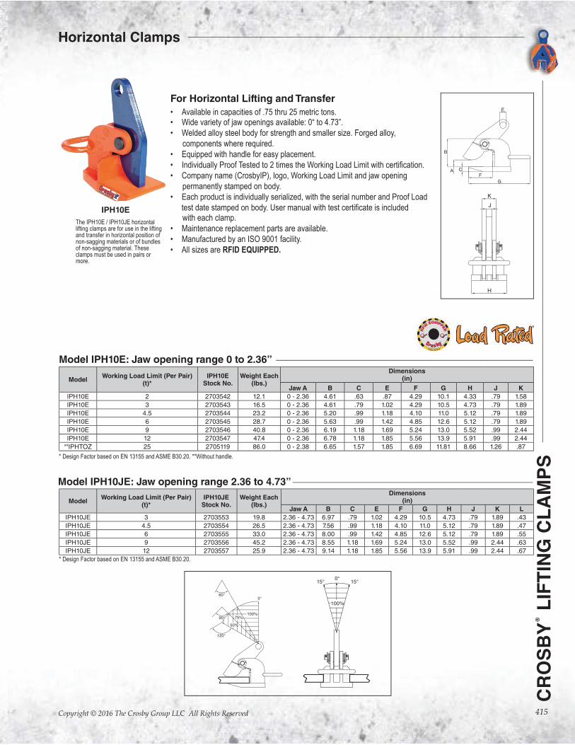
IPH10E
For Horizontal Lifting and Transfer
• Available in capacities of .75 thru 25 metric tons.• Wide variety of jaw openings available: 0“ to 4.73”.
• Welded alloy steel body for strength and smaller size. Forged alloy,
components where required.
• Equipped with handle for easy placement.
•
• Company name (CrosbyIP), logo, Working Load Limit and jaw opening
permanently stamped on body.
• Each product is individually serialized, with the serial number and Proof Load
test date stamped on body. with each clamp.
• Maintenance replacement parts are available.
• Manufactured by an ISO 9001 facility.
• All sizes are RFID EQUIPPED.
The IPH10E / IPH10JE horizontal lifting clamps are for use in the lifting and transfer in horizontal position of non-sagging materials or of bundles of non-sagging material. These clamps must be used in pairs or more.
ModelWorking Load Limit (Per Pair)
(t)*IPH10E
Stock No.Weight Each
(lbs.)
Dimensions (in)
Jaw A B C E F G H J K
IPH10E 2 2703542 12.1 0 - 2.36 4.61 .63 .87 4.29 10.1 4.33 .79 1.58
IPH10E 3 2703543 16.5 0 - 2.36 4.61 .79 1.02 4.29 10.5 4.73 .79 1.89
IPH10E 4.5 2703544 23.2 0 - 2.36 5.20 .99 1.18 4.10 11.0 5.12 .79 1.89
IPH10E 6 2703545 28.7 0 - 2.36 5.63 .99 1.42 4.85 12.6 5.12 .79 1.89
IPH10E 9 2703546 40.8 0 - 2.36 6.19 1.18 1.69 5.24 13.0 5.52 .99 2.44
IPH10E 12 2703547 47.4 0 - 2.36 6.78 1.18 1.85 5.56 13.9 5.91 .99 2.44
**IPHTOZ 25 2705119 86.0 0 - 2.38 6.65 1.57 1.85 6.69 11.81 8.66 1.26 .87
Model IPH10E: Jaw opening range 0 to 2.36”
ModelWorking Load Limit (Per Pair)
(t)*IPH10JE
Stock No.Weight Each
(lbs.)
Dimensions (in)
Jaw A B C E F G H J K L
IPH10JE 3 2703553 19.8 2.36 - 4.73 6.97 .79 1.02 4.29 10.5 4.73 .79 1.89 .43
IPH10JE 4.5 2703554 26.5 2.36 - 4.73 7.56 .99 1.18 4.10 11.0 5.12 .79 1.89 .47
IPH10JE 6 2703555 33.0 2.36 - 4.73 8.00 .99 1.42 4.85 12.6 5.12 .79 1.89 .55
IPH10JE 9 2703556 45.2 2.36 - 4.73 8.55 1.18 1.69 5.24 13.0 5.52 .99 2.44 .63
IPH10JE 12 2703557 25.9 2.36 - 4.73 9.14 1.18 1.85 5.56 13.9 5.91 .99 2.44 .67
Model IPH10JE: Jaw opening range 2.36 to 4.73”
* Design Factor based on EN 13155 and ASME B30.20.
Horizontal Clamps
* Design Factor based on EN 13155 and ASME B30.20. **Without handle.
416
CR
OS
BY
® L
IFT
ING
CL
AM
PS
Copyright © 2016 The Crosby Group LLC All Rights Reserved
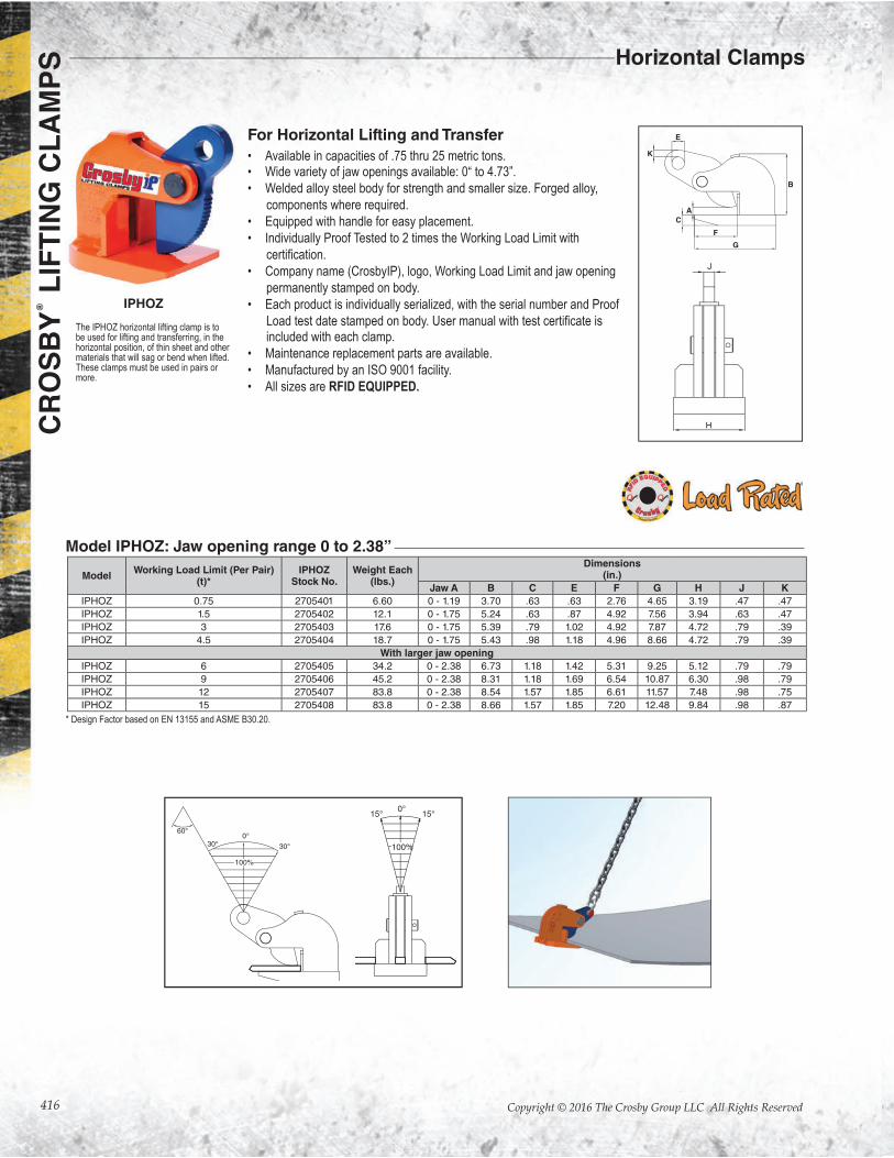
The IPHOZ horizontal lifting clamp is to be used for lifting and transferring, in the horizontal position, of thin sheet and other materials that will sag or bend when lifted. These clamps must be used in pairs or more.
IPHOZ
ModelWorking Load Limit (Per Pair)
(t)*IPHOZ
Stock No.Weight Each
(lbs.)
Dimensions (in.)
Jaw A B C E F G H J K
IPHOZ 0.75 2705401 6.60 0 - 1.19 3.70 .63 .63 2.76 4.65 3.19 .47 .47
IPHOZ 1.5 2705402 12.1 0 - 1.75 5.24 .63 .87 4.92 7.56 3.94 .63 .47
IPHOZ 3 2705403 17.6 0 - 1.75 5.39 .79 1.02 4.92 7.87 4.72 .79 .39
IPHOZ 4.5 2705404 18.7 0 - 1.75 5.43 .98 1.18 4.96 8.66 4.72 .79 .39
With larger jaw opening
IPHOZ 6 2705405 34.2 0 - 2.38 6.73 1.18 1.42 5.31 9.25 5.12 .79 .79
IPHOZ 9 2705406 45.2 0 - 2.38 8.31 1.18 1.69 6.54 10.87 6.30 .98 .79
IPHOZ 12 2705407 83.8 0 - 2.38 8.54 1.57 1.85 6.61 11.57 7.48 .98 .75
IPHOZ 15 2705408 83.8 0 - 2.38 8.66 1.57 1.85 7.20 12.48 9.84 .98 .87
Model IPHOZ: Jaw opening range 0 to 2.38”
E
B
G
F
A
C
K
For Horizontal Lifting and Transfer
• Available in capacities of .75 thru 25 metric tons.• Wide variety of jaw openings available: 0“ to 4.73”.
• Welded alloy steel body for strength and smaller size. Forged alloy,
components where required.
• Equipped with handle for easy placement.
• Individually Proof Tested to 2 times the Working Load Limit with
• Company name (CrosbyIP), logo, Working Load Limit and jaw opening
permanently stamped on body.
• Each product is individually serialized, with the serial number and Proof
Load test date stamped on body. included with each clamp.
• Maintenance replacement parts are available.
• Manufactured by an ISO 9001 facility.
• All sizes are RFID EQUIPPED.
* Design Factor based on EN 13155 and ASME B30.20.
Horizontal Clamps
417
CR
OS
BY
® L
IFT
ING
CL
AM
PS
Copyright © 2016 The Crosby Group LLC All Rights Reserved
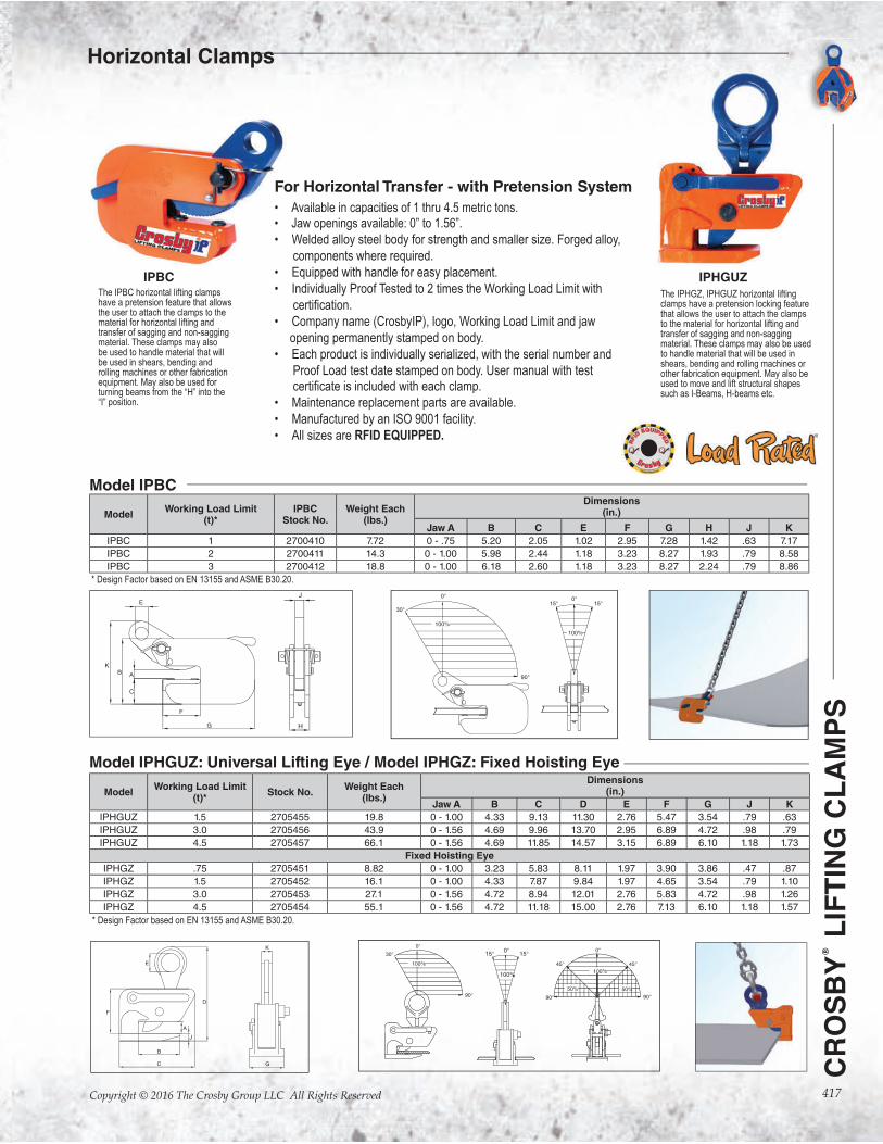
For Horizontal Transfer - with Pretension System
• Available in capacities of 1 thru 4.5 metric tons.
• Jaw openings available: 0” to 1.56”.
• Welded alloy steel body for strength and smaller size. Forged alloy,
components where required.
• Equipped with handle for easy placement.
• Individually Proof Tested to 2 times the Working Load Limit with
• Company name (CrosbyIP), logo, Working Load Limit and jaw
opening permanently stamped on body.
• Each product is individually serialized, with the serial number and
Proof Load test date stamped on body. User manual with test
• Maintenance replacement parts are available.
• Manufactured by an ISO 9001 facility.
• All sizes are RFID EQUIPPED.
The IPBC horizontal lifting clamps have a pretension feature that allows the user to attach the clamps to the material for horizontal lifting and transfer of sagging and non-sagging material. These clamps may also be used to handle material that will be used in shears, bending and rolling machines or other fabrication equipment. May also be used for turning beams from the “H” into the “I” position.
The IPHGZ, IPHGUZ horizontal lifting clamps have a pretension locking feature that allows the user to attach the clamps to the material for horizontal lifting and transfer of sagging and non-sagging material. These clamps may also be used to handle material that will be used in shears, bending and rolling machines or other fabrication equipment. May also be used to move and lift structural shapes such as I-Beams, H-beams etc.
IPBC IPHGUZ
ModelWorking Load Limit
(t)*Stock No.
Weight Each(lbs.)
Dimensions (in.)
Jaw A B C D E F G J K
IPHGUZ 1.5 2705455 19.8 0 - 1.00 4.33 9.13 11.30 2.76 5.47 3.54 .79 .63
IPHGUZ 3.0 2705456 43.9 0 - 1.56 4.69 9.96 13.70 2.95 6.89 4.72 .98 .79
IPHGUZ 4.5 2705457 66.1 0 - 1.56 4.69 11.85 14.57 3.15 6.89 6.10 1.18 1.73
Fixed Hoisting Eye
IPHGZ .75 2705451 8.82 0 - 1.00 3.23 5.83 8.11 1.97 3.90 3.86 .47 .87
IPHGZ 1.5 2705452 16.1 0 - 1.00 4.33 7.87 9.84 1.97 4.65 3.54 .79 1.10
IPHGZ 3.0 2705453 27.1 0 - 1.56 4.72 8.94 12.01 2.76 5.83 4.72 .98 1.26
IPHGZ 4.5 2705454 55.1 0 - 1.56 4.72 11.18 15.00 2.76 7.13 6.10 1.18 1.57
Model IPHGUZ: Universal Lifting Eye / Model IPHGZ: Fixed Hoisting Eye
* Design Factor based on EN 13155 and ASME B30.20.
ModelWorking Load Limit
(t)*IPBC
Stock No.Weight Each
(lbs.)
Dimensions (in.)
Jaw A B C E F G H J K
IPBC 1 2700410 7.72 0 - .75 5.20 2.05 1.02 2.95 7.28 1.42 .63 7.17
IPBC 2 2700411 14.3 0 - 1.00 5.98 2.44 1.18 3.23 8.27 1.93 .79 8.58
IPBC 3 2700412 18.8 0 - 1.00 6.18 2.60 1.18 3.23 8.27 2.24 .79 8.86
Model IPBC
* Design Factor based on EN 13155 and ASME B30.20.
J
Horizontal Clamps
418
CR
OS
BY
® L
IFT
ING
CL
AM
PS
Copyright © 2016 The Crosby Group LLC All Rights Reserved
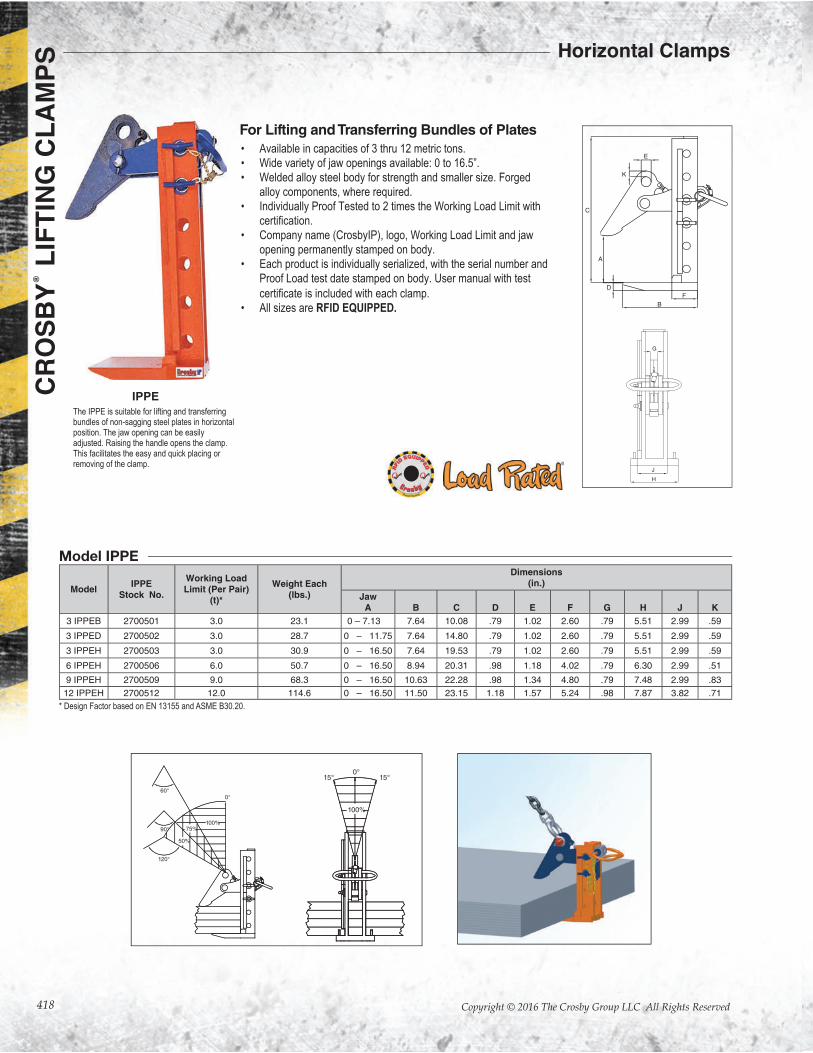
• Available in capacities of 3 thru 12 metric tons.
• Wide variety of jaw openings available: 0 to 16.5”.
• Welded alloy steel body for strength and smaller size. Forged
alloy components, where required.
• Individually Proof Tested to 2 times the Working Load Limit with
• Company name (CrosbyIP), logo, Working Load Limit and jaw
opening permanently stamped on body.
• Each product is individually serialized, with the serial number and
Proof Load test date stamped on body. User manual with test
• All sizes are RFID EQUIPPED.
For Lifting and Transferring Bundles of Plates
The IPPE is suitable for lifting and transferring bundles of non-sagging steel plates in horizontal position. The jaw opening can be easily adjusted. Raising the handle opens the clamp. This facilitates the easy and quick placing or removing of the clamp.
Model IPPE
IPPE
ModelIPPE
Stock No.
Working Load Limit (Per Pair)
(t)*
Weight Each (lbs.)
Dimensions (in.)
Jaw A B C D E F G H J K
3 IPPEB 2700501 3.0 23.1 0 – 7.13 7.64 10.08 .79 1.02 2.60 .79 5.51 2.99 .59
3 IPPED 2700502 3.0 28.7 0 – 11.75 7.64 14.80 .79 1.02 2.60 .79 5.51 2.99 .59
3 IPPEH 2700503 3.0 30.9 0 – 16.50 7.64 19.53 .79 1.02 2.60 .79 5.51 2.99 .59
6 IPPEH 2700506 6.0 50.7 0 – 16.50 8.94 20.31 .98 1.18 4.02 .79 6.30 2.99 .51
9 IPPEH 2700509 9.0 68.3 0 – 16.50 10.63 22.28 .98 1.34 4.80 .79 7.48 2.99 .83
12 IPPEH 2700512 12.0 114.6 0 – 16.50 11.50 23.15 1.18 1.57 5.24 .98 7.87 3.82 .71
* Design Factor based on EN 13155 and ASME B30.20.
Horizontal Clamps
419
CR
OS
BY
® L
IFT
ING
CL
AM
PS
Copyright © 2016 The Crosby Group LLC All Rights Reserved
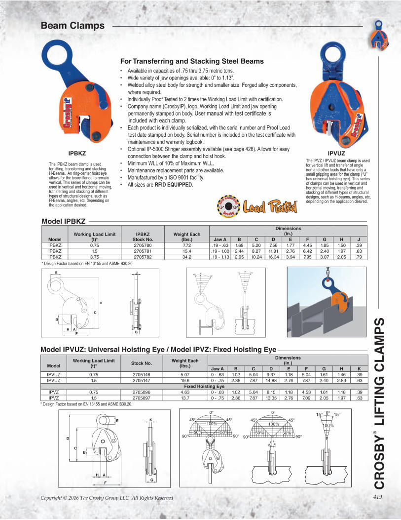
For Transferring and Stacking Steel Beams
• Available in capacities of .75 thru 3.75 metric tons.
• Wide variety of jaw openings available: 0” to 1.13”.
• Welded alloy steel body for strength and smaller size. Forged alloy components,
where required.
•
• Company name (CrosbyIP), logo, Working Load Limit and jaw opening
permanently stamped on body.
included with each clamp.• Each product is individually serialized, with the serial number and Proof Load
maintenance and warranty logbook.
• Optional IP-5000 Stinger assembly available (see page 428). Allows for easy
connection between the clamp and hoist hook.
• Minimum WLL of 10% of Maximum WLL.
• Maintenance replacement parts are available.
• Manufactured by a ISO 9001 facility.
• All sizes are RFID EQUIPPED.
The IPBKZ beam clamp is used for lifting, transferring and stacking H-Beams. An ring-center hoist eye
vertical. This series of clamps can be used in vertical and horizontal moving, transferring and stacking of different types of structural designs, such as H-Beams, angles, etc, depending on the application desired.
The IPVZ / IPVUZ beam clamp is used for vertical lift and transfer of angle iron and other loads that have only a small gripping area for the clamp (“U” has universal hoisting eye). This series of clamps can be used in vertical and horizontal moving, transferring and stacking of different types of structural designs, such as H-beams, angles, etc, depending on the application desired.
K
G
B
A
C
F
E
H
D
IPBKZ IPVUZ
ModelWorking Load Limit
(t)*Stock No.
Weight Each(lbs.)
Dimensions (in.)
Jaw A B C D E F G H K
IPVUZ 0.75 2705146 5.07 0 - .63 1.02 5.04 9.37 1.18 5.04 1.61 1.46 .39
IPVUZ 1.5 2705147 19.6 0 - .75 2.36 7.87 14.88 2.76 7.87 2.40 2.83 .63
Fixed Hoisting Eye
IPVZ 0.75 2705096 4.63 0 - .63 1.02 5.04 8.15 1.18 4.53 1.61 1.18 .39
IPVZ 1.5 2705097 13.7 0 - .75 2.36 7.87 13.35 2.76 7.09 2.05 1.97 .63
Model IPVUZ: Universal Hoisting Eye / Model IPVZ: Fixed Hoisting Eye
* Design Factor based on EN 13155 and ASME B30.20.
ModelWorking Load Limit
(t)*IPBKZ
Stock No.Weight Each
(lbs.)
Dimensions (in.)
Jaw A B C D E F G H J
IPBKZ 0.75 2705780 7.72 .19 - .63 1.69 5.20 7.56 1.77 4.45 1.85 1.50 .39
IPBKZ 1.5 2705781 15.4 .19 - 1.00 2.44 8.27 11.81 2.76 6.42 2.40 1.97 .63
IPBKZ 3.75 2705782 34.2 .19 - 1.13 2.95 10.24 16.34 3.94 7.95 3.07 2.05 .79
Model IPBKZ
* Design Factor based on EN 13155 and ASME B30.20.
J
G
B
H A
F
E
C
D
Beam Clamps
420
CR
OS
BY
® L
IFT
ING
CL
AM
PS
Copyright © 2016 The Crosby Group LLC All Rights Reserved
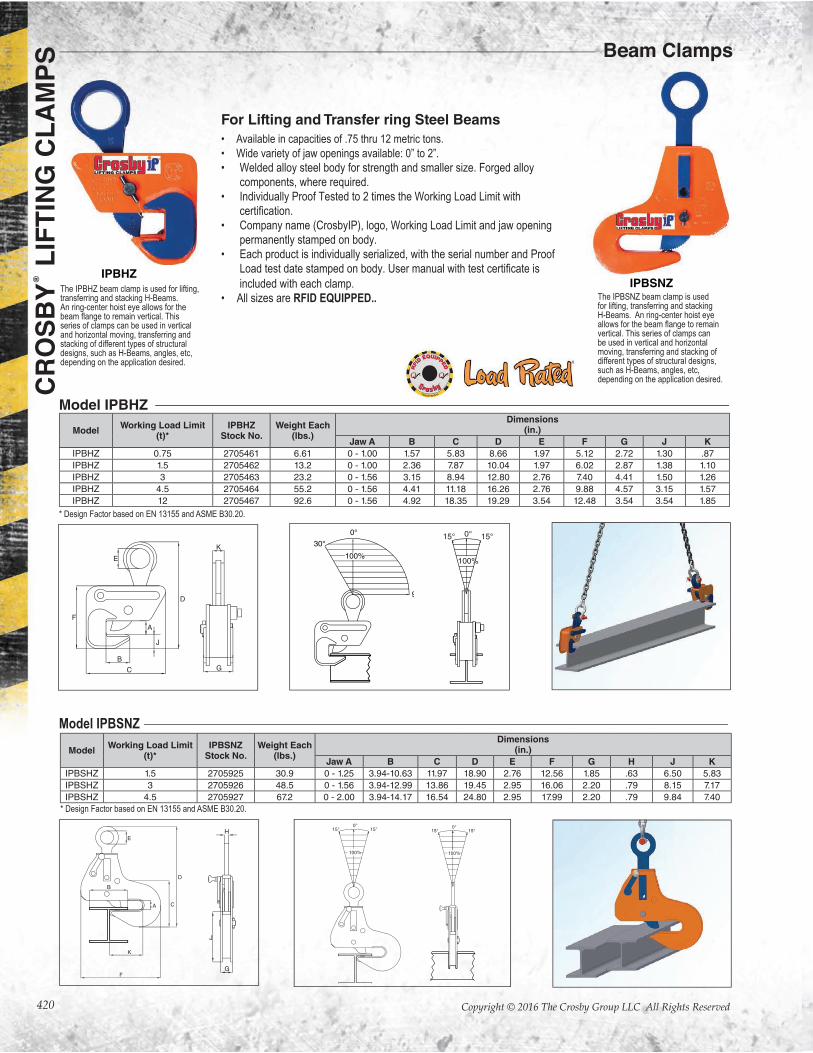
For Lifting and Transfer ring Steel Beams
• Available in capacities of .75 thru 12 metric tons.
• Wide variety of jaw openings available: 0” to 2”.
• Welded alloy steel body for strength and smaller size. Forged alloy
components, where required.
• Individually Proof Tested to 2 times the Working Load Limit with
• Company name (CrosbyIP), logo, Working Load Limit and jaw opening
permanently stamped on body.
• Each product is individually serialized, with the serial number and Proof
included with each clamp.
• All sizes are RFID EQUIPPED..The IPBHZ beam clamp is used for lifting, transferring and stacking H-Beams. An ring-center hoist eye allows for the
series of clamps can be used in vertical and horizontal moving, transferring and stacking of different types of structural designs, such as H-Beams, angles, etc, depending on the application desired.
The IPBSNZ beam clamp is used for lifting, transferring and stacking H-Beams. An ring-center hoist eye
vertical. This series of clamps can be used in vertical and horizontal moving, transferring and stacking of different types of structural designs, such as H-Beams, angles, etc, depending on the application desired.
IPBHZIPBSNZ
ModelWorking Load Limit
(t)*IPBHZ
Stock No.Weight Each
(lbs.)
Dimensions (in.)
Jaw A B C D E F G J K
IPBHZ 0.75 2705461 6.61 0 - 1.00 1.57 5.83 8.66 1.97 5.12 2.72 1.30 .87
IPBHZ 1.5 2705462 13.2 0 - 1.00 2.36 7.87 10.04 1.97 6.02 2.87 1.38 1.10
IPBHZ 3 2705463 23.2 0 - 1.56 3.15 8.94 12.80 2.76 7.40 4.41 1.50 1.26
IPBHZ 4.5 2705464 55.2 0 - 1.56 4.41 11.18 16.26 2.76 9.88 4.57 3.15 1.57
IPBHZ 12 2705467 92.6 0 - 1.56 4.92 18.35 19.29 3.54 12.48 3.54 3.54 1.85
ModelWorking Load Limit
(t)*IPBSNZ
Stock No.Weight Each
(lbs.)
Dimensions (in.)
Jaw A B C D E F G H J K
IPBSHZ 1.5 2705925 30.9 0 - 1.25 3.94-10.63 11.97 18.90 2.76 12.56 1.85 .63 6.50 5.83
IPBSHZ 3 2705926 48.5 0 - 1.56 3.94-12.99 13.86 19.45 2.95 16.06 2.20 .79 8.15 7.17
IPBSHZ 4.5 2705927 67.2 0 - 2.00 3.94-14.17 16.54 24.80 2.95 17.99 2.20 .79 9.84 7.40
Model IPBHZ
* Design Factor based on EN 13155 and ASME B30.20.
Model IPBSNZ
* Design Factor based on EN 13155 and ASME B30.20.
Beam Clamps
421
CR
OS
BY
® L
IFT
ING
CL
AM
PS
Copyright © 2016 The Crosby Group LLC All Rights Reserved
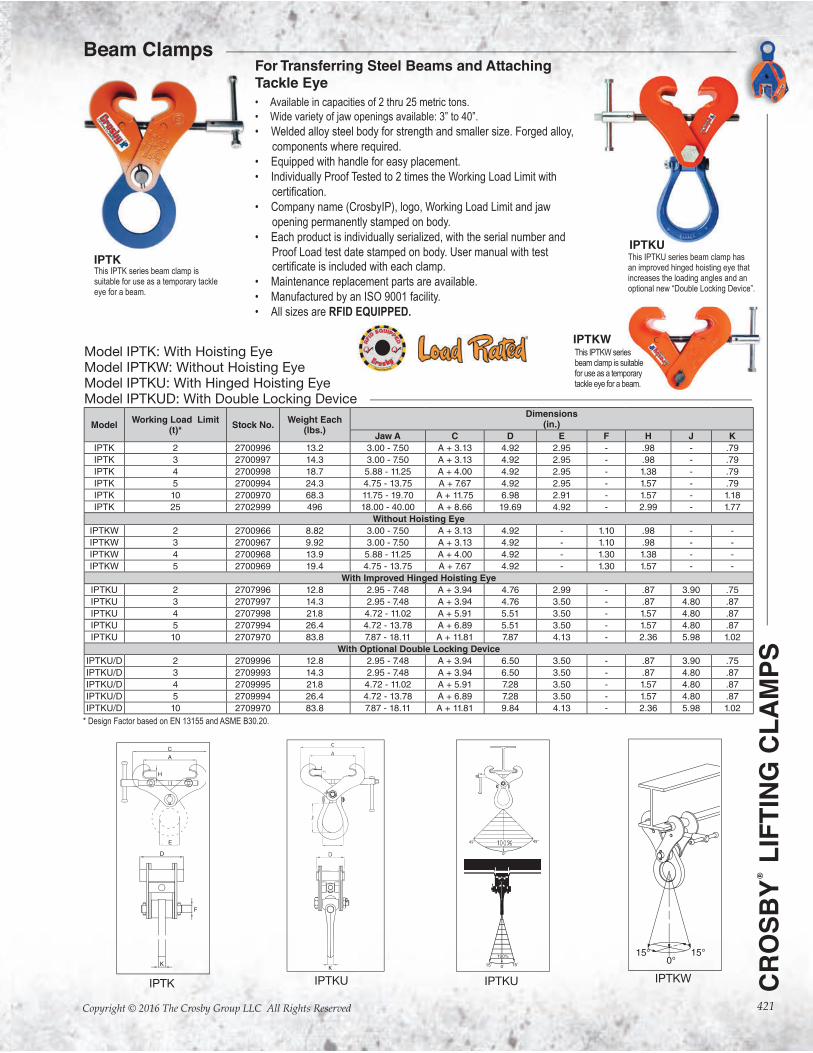
For Transferring Steel Beams and Attaching Tackle Eye
• Available in capacities of 2 thru 25 metric tons.
• Wide variety of jaw openings available: 3” to 40”.
• Welded alloy steel body for strength and smaller size. Forged alloy,
components where required.
• Equipped with handle for easy placement.
• Individually Proof Tested to 2 times the Working Load Limit with
• Company name (CrosbyIP), logo, Working Load Limit and jaw
opening permanently stamped on body.
• Each product is individually serialized, with the serial number and
Proof Load test date stamped on body. User manual with test
• Maintenance replacement parts are available.
• Manufactured by an ISO 9001 facility.
• All sizes are RFID EQUIPPED.
This IPTK series beam clamp is suitable for use as a temporary tackle eye for a beam.
IPTK
IPTKU
IPTK IPTKU IPTKU
ModelWorking Load Limit
(t)*Stock No.
Weight Each(lbs.)
Dimensions (in.)
Jaw A C D E F H J K
IPTK 2 2700996 13.2 3.00 - 7.50 A + 3.13 4.92 2.95 - .98 - .79
IPTK 3 2700997 14.3 3.00 - 7.50 A + 3.13 4.92 2.95 - .98 - .79
IPTK 4 2700998 18.7 5.88 - 11.25 A + 4.00 4.92 2.95 - 1.38 - .79
IPTK 5 2700994 24.3 4.75 - 13.75 A + 7.67 4.92 2.95 - 1.57 - .79
IPTK 10 2700970 68.3 11.75 - 19.70 A + 11.75 6.98 2.91 - 1.57 - 1.18
IPTK 25 2702999 496 18.00 - 40.00 A + 8.66 19.69 4.92 - 2.99 - 1.77
Without Hoisting Eye
IPTKW 2 2700966 8.82 3.00 - 7.50 A + 3.13 4.92 - 1.10 .98 - -
IPTKW 3 2700967 9.92 3.00 - 7.50 A + 3.13 4.92 - 1.10 .98 - -
IPTKW 4 2700968 13.9 5.88 - 11.25 A + 4.00 4.92 - 1.30 1.38 - -
IPTKW 5 2700969 19.4 4.75 - 13.75 A + 7.67 4.92 - 1.30 1.57 - -
With Improved Hinged Hoisting Eye
IPTKU 2 2707996 12.8 2.95 - 7.48 A + 3.94 4.76 2.99 - .87 3.90 .75
IPTKU 3 2707997 14.3 2.95 - 7.48 A + 3.94 4.76 3.50 - .87 4.80 .87
IPTKU 4 2707998 21.8 4.72 - 11.02 A + 5.91 5.51 3.50 - 1.57 4.80 .87
IPTKU 5 2707994 26.4 4.72 - 13.78 A + 6.89 5.51 3.50 - 1.57 4.80 .87
IPTKU 10 2707970 83.8 7.87 - 18.11 A + 11.81 7.87 4.13 - 2.36 5.98 1.02
With Optional Double Locking Device
IPTKU/D 2 2709996 12.8 2.95 - 7.48 A + 3.94 6.50 3.50 - .87 3.90 .75
IPTKU/D 3 2709993 14.3 2.95 - 7.48 A + 3.94 6.50 3.50 - .87 4.80 .87
IPTKU/D 4 2709995 21.8 4.72 - 11.02 A + 5.91 7.28 3.50 - 1.57 4.80 .87
IPTKU/D 5 2709994 26.4 4.72 - 13.78 A + 6.89 7.28 3.50 - 1.57 4.80 .87
IPTKU/D 10 2709970 83.8 7.87 - 18.11 A + 11.81 9.84 4.13 - 2.36 5.98 1.02
Model IPTK: With Hoisting EyeModel IPTKW: Without Hoisting EyeModel IPTKU: With Hinged Hoisting EyeModel IPTKUD: With Double Locking Device
* Design Factor based on EN 13155 and ASME B30.20.
IPTKW
45°45°
0°
This IPTKU series beam clamp has an improved hinged hoisting eye that increases the loading angles and an optional new “Double Locking Device”.
Beam Clamps
IPTKWThis IPTKW series beam clamp is suitable for use as a temporary tackle eye for a beam.
422
CR
OS
BY
® L
IFT
ING
CL
AM
PS
Copyright © 2016 The Crosby Group LLC All Rights Reserved
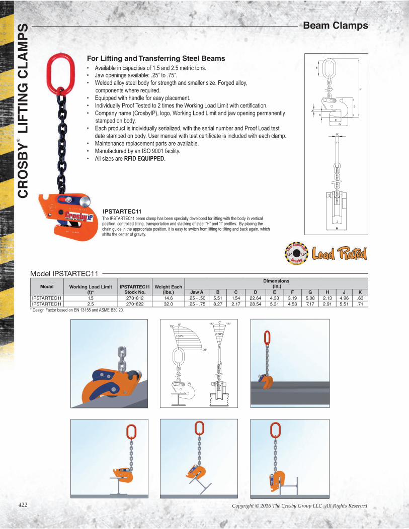
For Lifting and Transferring Steel Beams
• Available in capacities of 1.5 and 2.5 metric tons.• Jaw openings available: .25” to .75”.
• Welded alloy steel body for strength and smaller size. Forged alloy,
components where required.
• Equipped with handle for easy placement.
•
• Company name (CrosbyIP), logo, Working Load Limit and jaw opening permanently
stamped on body.
• Each product is individually serialized, with the serial number and Proof Load test
date stamped on body.
• Maintenance replacement parts are available.
• Manufactured by an ISO 9001 facility.
• All sizes are RFID EQUIPPED.
The IPSTARTEC11 beam clamp has been specially developed for lifting with the body in vertical
chain guide in the appropriate position, it is easy to switch from lifting to tilting and back again, which shifts the center of gravity.
Model Working Load Limit(t)*
IPSTARTEC11Stock No.
Weight Each(lbs.)
Dimensions (in.)
Jaw A B C D E F G H J K
IPSTARTEC11 1.5 2701812 14.6 .25 - .50 5.51 1.54 22.64 4.33 3.19 5.08 2.13 4.96 .63
IPSTARTEC11 2.5 2701822 32.0 .25 - .75 8.27 2.17 28.54 5.31 4.53 7.17 2.91 5.51 .71
Model IPSTARTEC11
* Design Factor based on EN 13155 and ASME B30.20.
IPSTARTEC11
Beam Clamps
423
CR
OS
BY
® L
IFT
ING
CL
AM
PS
Copyright © 2016 The Crosby Group LLC All Rights Reserved
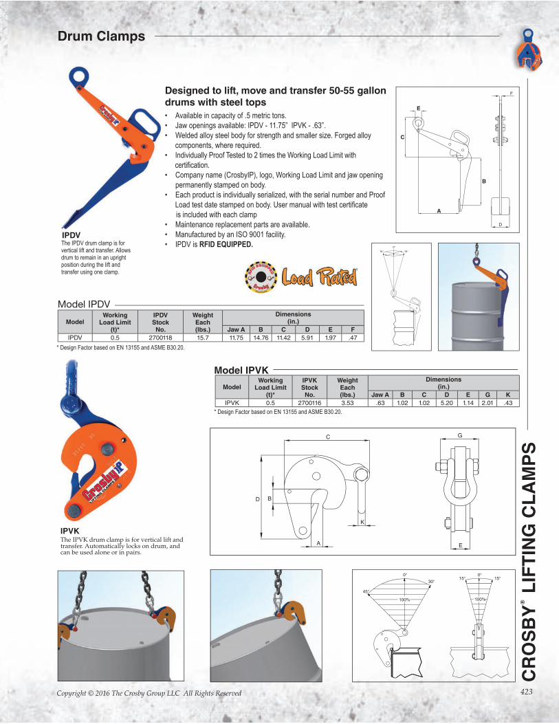
Designed to lift, move and transfer 50-55 gallon drums with steel tops
• Available in capacity of .5 metric tons.
• Jaw openings available: IPDV - 11.75” IPVK - .63”.
• Welded alloy steel body for strength and smaller size. Forged alloy
components, where required.
• Individually Proof Tested to 2 times the Working Load Limit with
• Company name (CrosbyIP), logo, Working Load Limit and jaw opening
permanently stamped on body.
• Each product is individually serialized, with the serial number and Proof
is included with each clamp
• Maintenance replacement parts are available.
• Manufactured by an ISO 9001 facility.
• IPDV is RFID EQUIPPED.The IPDV drum clamp is for vertical lift and transfer. Allows drum to remain in an upright position during the lift and transfer using one clamp.
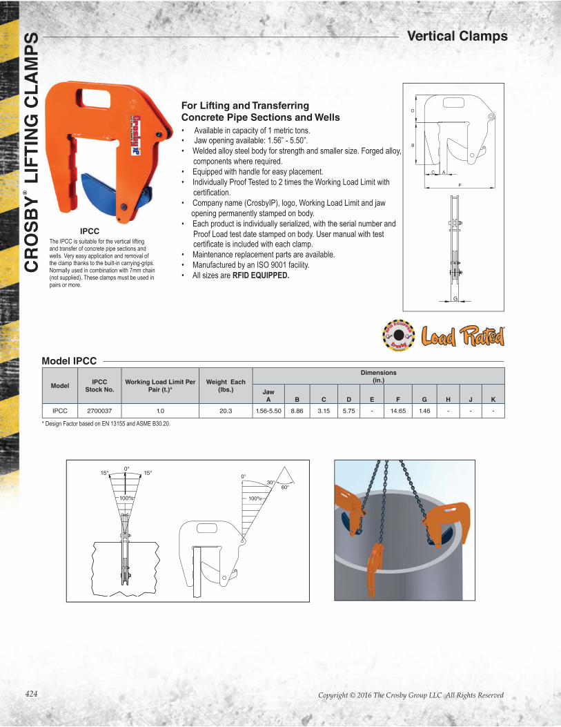
The IPVK drum clamp is for vertical lift and transfer. Automatically locks on drum, and can be used alone or in pairs.
E
C
B
A
IPDV
IPVK
ModelWorking
Load Limit(t)*
IPDVStock
No.
WeightEach(lbs.)
Dimensions(in.)
Jaw A B C D E F
IPDV 0.5 2700118 15.7 11.75 14.76 11.42 5.91 1.97 .47
Model IPDV
* Design Factor based on EN 13155 and ASME B30.20.
ModelWorking
Load Limit(t)*
IPVKStockNo.
WeightEach(lbs.)
Dimensions(in.)
Jaw A B C D E G K
IPVK 0.5 2700116 3.53 .63 1.02 1.02 5.20 1.14 2.01 .43
Model IPVK
* Design Factor based on EN 13155 and ASME B30.20.
Drum Clamps
424
CR
OS
BY
® L
IFT
ING
CL
AM
PS
Copyright © 2016 The Crosby Group LLC All Rights Reserved
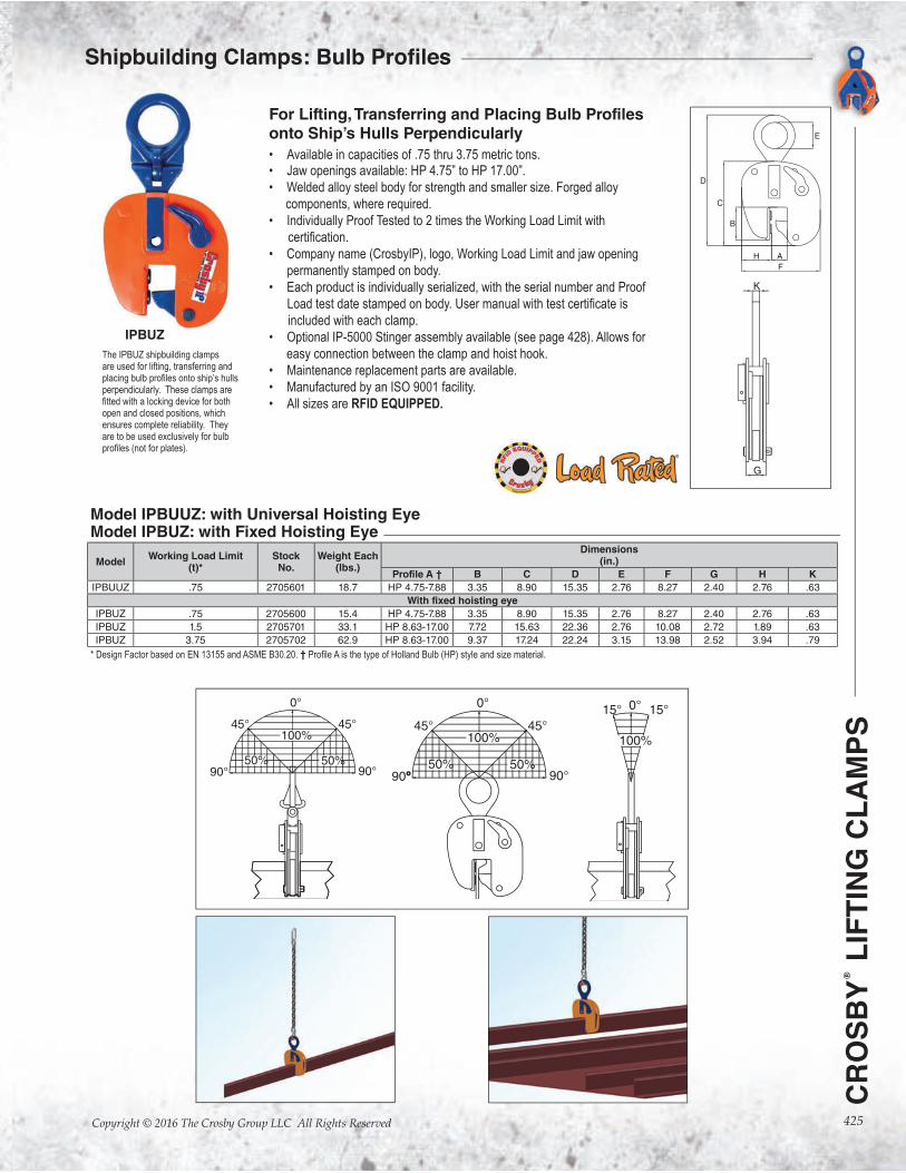
IPCC
For Lifting and Transferring Concrete Pipe Sections and Wells
Model IPCC
• Available in capacity of 1 metric tons.• Jaw opening available: 1.56” - 5.50”.
• Welded alloy steel body for strength and smaller size. Forged alloy,
components where required.
• Equipped with handle for easy placement.
• Individually Proof Tested to 2 times the Working Load Limit with
• Company name (CrosbyIP), logo, Working Load Limit and jaw
opening permanently stamped on body.
• Each product is individually serialized, with the serial number and
Proof Load test date stamped on body. User manual with test
• Maintenance replacement parts are available.
• Manufactured by an ISO 9001 facility.
• All sizes are RFID EQUIPPED.
ModelIPCC
Stock No.Working Load Limit Per
Pair (t.)*Weight Each
(lbs.)
Dimensions(in.)
JawA B C D E F G H J K
IPCC 2700037 1.0 20.3 1.56-5.50 8.86 3.15 5.75 - 14.65 1.46 - - -
* Design Factor based on EN 13155 and ASME B30.20.
AC
F
B
D
G
100%
0°15°15°
The IPCC is suitable for the vertical lifting and transfer of concrete pipe sections and wells. Very easy application and removal of the clamp thanks to the built-in carrying-grips. Normally used in combination with 7mm chain (not supplied). These clamps must be used in pairs or more.
Vertical Clamps
425
CR
OS
BY
® L
IFT
ING
CL
AM
PS
Copyright © 2016 The Crosby Group LLC All Rights Reserved
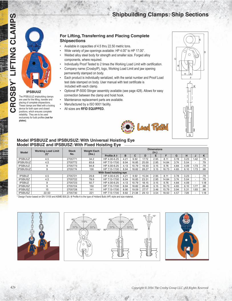
For Lifting, Transferring and Placing Bulb Profiles onto Ship’s Hulls Perpendicularly
• Available in capacities of .75 thru 3.75 metric tons.• Jaw openings available: HP 4.75” to HP 17.00”.
• Welded alloy steel body for strength and smaller size. Forged alloy
components, where required.
• Individually Proof Tested to 2 times the Working Load Limit with
• Company name (CrosbyIP), logo, Working Load Limit and jaw opening
permanently stamped on body.
• Each product is individually serialized, with the serial number and Proof
Load test date stamped on body.
included with each clamp.
• Optional IP-5000 Stinger assembly available (see page 428). Allows for
easy connection between the clamp and hoist hook.
• Maintenance replacement parts are available.
• Manufactured by an ISO 9001 facility.
• All sizes are RFID EQUIPPED.
The IPBUZ shipbuilding clamps are used for lifting, transferring and
perpendicularly. These clamps are
open and closed positions, which ensures complete reliability. They are to be used exclusively for bulb
0° 15°15°
100%
IPBUZ
ModelWorking Load Limit
(t)*StockNo.
Weight Each(lbs.)
Dimensions(in.)
Profile A † B C D E F G H K
IPBUUZ .75 2705601 18.7 HP 4.75-7.88 3.35 8.90 15.35 2.76 8.27 2.40 2.76 .63
With fixed hoisting eye
IPBUZ .75 2705600 15.4 HP 4.75-7.88 3.35 8.90 15.35 2.76 8.27 2.40 2.76 .63
IPBUZ 1.5 2705701 33.1 HP 8.63-17.00 7.72 15.63 22.36 2.76 10.08 2.72 1.89 .63
IPBUZ 3.75 2705702 62.9 HP 8.63-17.00 9.37 17.24 22.24 3.15 13.98 2.52 3.94 .79
Model IPBUUZ: with Universal Hoisting EyeModel IPBUZ: with Fixed Hoisting Eye
* Design Factor based on EN 13155 and ASME B30.20. †
426
CR
OS
BY
® L
IFT
ING
CL
AM
PS
Copyright © 2016 The Crosby Group LLC All Rights Reserved
For Lifting, Transferring and Placing Complete Shipsections
• Available in capacities of 4.5 thru 22.50 metric tons.
• Wide variety of jaw openings available: HP 4.00” to HP 17.00”.
• Welded alloy steel body for strength and smaller size. Forged alloy
components, where required.
•
• Company name (CrosbyIP), logo, Working Load Limit and jaw opening
permanently stamped on body.
• Each product is individually serialized, with the serial number and Proof Load
included with each clamp.
• Optional IP-5000 Stinger assembly available (see page 428). Allows for easy
connection between the clamp and hoist hook.
• Maintenance replacement parts are available.
• Manufactured by a ISO 9001 facility.
• All sizes are RFID EQUIPPED.
The IPSBU(U)Z shipbuilding clamps are used for the lifting, transfer and placing of complete shipsections.
device for both open and closed positions, which ensures complete reliability. They are to be used
(not for plates).
IPSBUUZ
ModelWorking Load Limit
(t)*Stock
No.Weight Each
(lbs.)
Dimensions(in.)
Profile A † B C D E F G H J K
IPSBUUZ 4.5 2705771 34.2 HP 4.00-6.25 4.21 9.92 17.72 2.95 8.11 3.78 3.23 1.42 .79
IPSBUSUZ 4.5 2705772 83.8 HP 7.13-17.00 8.94 16.85 25.00 2.95 14.84 3.74 5.04 - .79
IPSBUUZ 9 2705773 94.8 HP 4.00-6.25 4.13 10.79 19.33 3.15 9.76 4.84 4.09 1.73 .79
IPSBUSUZ 9 2705774 130 HP 7.13-17.00 8.94 18.82 28.27 3.15 16.73 4.65 6.10 1.73 .98
With fixed hoisting eye
IPSBUZ 4.5 2705721 29.8 HP 4.00-6.25 4.21 9.92 15.04 2.95 8.11 3.78 3.23 - .79
IPSBUSZ 4.5 2705722 78.9 HP 7.13-17.00 8.94 16.85 23.31 2.95 14.84 3.74 5.04 - .79
IPSBUZ 9 2705723 50.7 HP 4.00-6.25 4.13 10.79 18.15 3.15 9.76 4.84 4.09 - 1.18
IPSBUSZ 9 2705724 150 HP 7.13-17.00 8.94 18.82 26.46 3.15 16.73 4.65 6.10 1.77 .98
IPSBUSZ 15 2705728 141 HP 7.13-17.00 8.90 19.09 27.17 3.46 15.79 3.94 5.31 1.93 .98
IPSBUSZ 22.50 2705730 221 HP 7.13-17.00 8.82 21.38 29.13 3.54 18.50 4.57 7.28 - 1.18
Model IPSBUUZ and IPSBUSUZ: With Universal Hoisting EyeModel IPSBUZ and IPSBUSZ: With Fixed Hoisting Eye
* Design Factor based on EN 13155 and ASME B30.20. †
Shipbuilding Clamps: Ship Sections
427
CR
OS
BY
® L
IFT
ING
CL
AM
PS
Copyright © 2016 The Crosby Group LLC All Rights Reserved
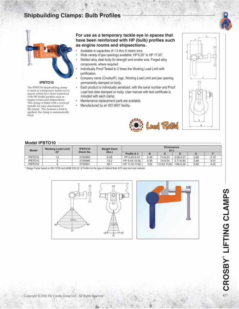
For use as a temporary tackle eye in spaces that have been reinforced with HP (bulb) profiles such as engine rooms and shipsections.
• Available in capacities of 1.5 thru 6 metric tons.• Wide variety of jaw openings available: HP 6.25” to HP 17.00”.
• Welded alloy steel body for strength and smaller size. Forged alloy
components, where required.
• Individually Proof Tested to 2 times the Working Load Limit with
• Company name (CrosbyIP), logo, Working Load Limit and jaw opening
permanently stamped on body.
• Each product is individually serialized, with the serial number and Proof
included with each clamp.
• Maintenance replacement parts are available.
• Manufactured by an ISO 9001 facility.
The IPBTO10 shipbuilding clamp is used as a temporary tackle eye in spaces which have been reinforced with HP (bulb) pro�les such as engine rooms and shipsections. This clamp is �tted with a screwed spindle for easy attachment of the clamp. The moment a load is applied, the clamp is automatically �xed.
IPBTO10
ModelWorking Load Limit
(t)*IPBTO10Stock No.
Weight Each(lbs.)
Dimensions(in.)
Profile A † B C D E F
IPBTO10 1.5 2700980 9.48 HP 6.25-9.44 5.39 7.4-8.23 5.08-5.91 2.68 3.19
IPBTO10 3 2700986 13.2 HP 9.44-12.56 5.39 7.4-8.54 5.71-6.85 2.68 3.07
IPBTO10 6 2700991 28.7 HP 11.75-17.00 7.28 10.03-11.69 7.68-9.29 3.86 4.02
Model IPBTO10
* Design Factor based on EN 13155 and ASME B30.20. †
Copyright © 2016 The Crosby Group LLC All Rights Reserved428
CR
OS
BY
®
LIF
TIN
G C
LA
MP
S
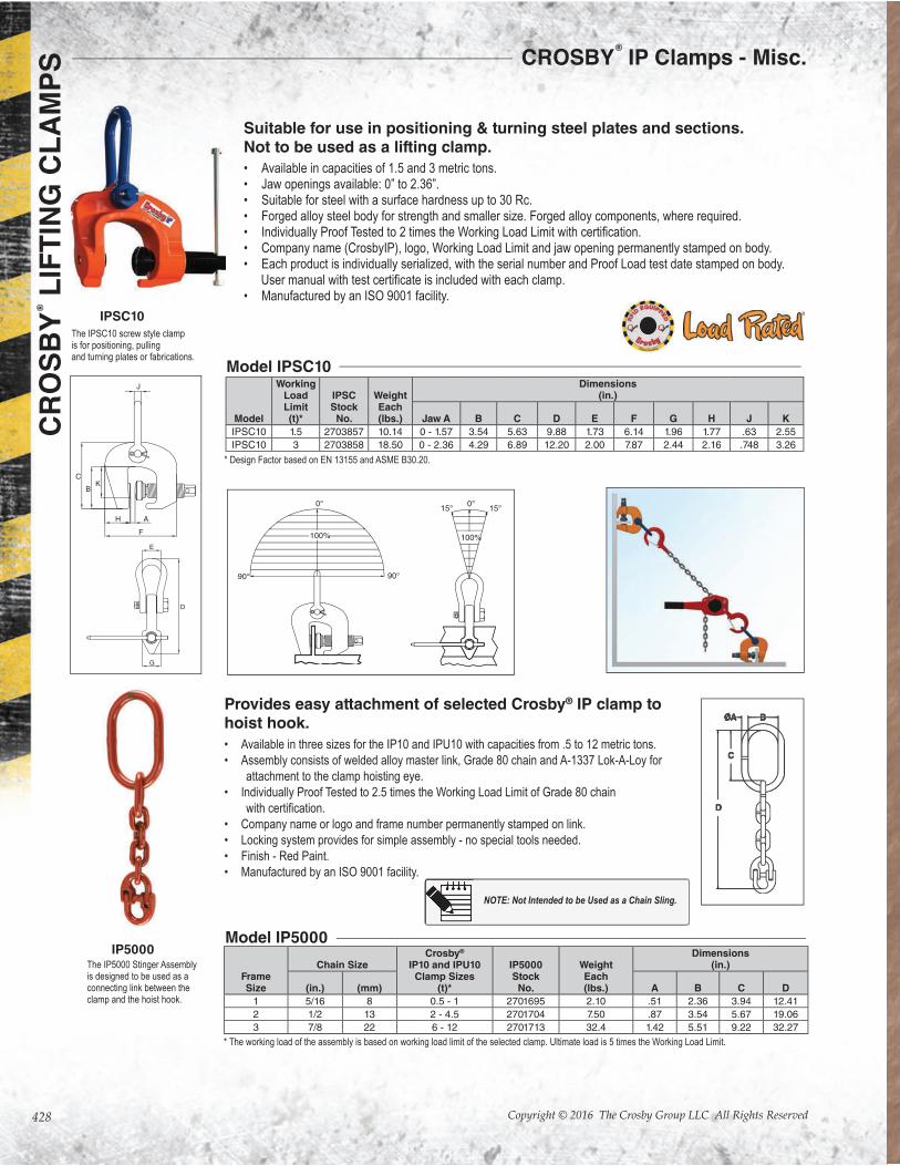
Suitable for use in positioning & turning steel plates and sections.Not to be used as a lifting clamp.
• Available in capacities of 1.5 and 3 metric tons.• Jaw openings available: 0” to 2.36”.• Suitable for steel with a surface hardness up to 30 Rc. • Forged alloy steel body for strength and smaller size. Forged alloy components, where required.• • Company name (CrosbyIP), logo, Working Load Limit and jaw opening permanently stamped on body.• Each product is individually serialized, with the serial number and Proof Load test date stamped on body.
• Manufactured by an ISO 9001 facility.
The IPSC10 screw style clamp is for positioning, pulling and turning plates or fabrications.
Provides easy attachment of selected Crosby® IP clamp to hoist hook.
• Available in three sizes for the IP10 and IPU10 with capacities from .5 to 12 metric tons.
• Assembly consists of welded alloy master link, Grade 80 chain and A-1337 Lok-A-Loy for
attachment to the clamp hoisting eye.
• Individually Proof Tested to 2.5 times the Working Load Limit of Grade 80 chain
• Company name or logo and frame number permanently stamped on link.
• Locking system provides for simple assembly - no special tools needed.
• Finish - Red Paint.
• Manufactured by an ISO 9001 facility.
The IP5000 Stinger Assembly is designed to be used as a connecting link between the clamp and the hoist hook.
IPSC10
IP5000
Model
WorkingLoad Limit(t)*
IPSCStock
No.
WeightEach(lbs.)
Dimensions(in.)
Jaw A B C D E F G H J K
IPSC10 1.5 2703857 10.14 0 - 1.57 3.54 5.63 9.88 1.73 6.14 1.96 1.77 .63 2.55
IPSC10 3 2703858 18.50 0 - 2.36 4.29 6.89 12.20 2.00 7.87 2.44 2.16 .748 3.26
Model IPSC10
* Design Factor based on EN 13155 and ASME B30.20.
FrameSize
Chain SizeCrosby®
IP10 and IPU10Clamp Sizes
(t)*
IP5000StockNo.
WeightEach(lbs.)
Dimensions(in.)
(in.) (mm) A B C D
1 5/16 8 0.5 - 1 2701695 2.10 .51 2.36 3.94 12.41
2 1/2 13 2 - 4.5 2701704 7.50 .87 3.54 5.67 19.06
3 7/8 22 6 - 12 2701713 32.4 1.42 5.51 9.22 32.27
Model IP5000
* The working load of the assembly is based on working load limit of the selected clamp. Ultimate load is 5 times the Working Load Limit.
CROSBY®
IP Clamps - Misc.
NOTE: Not Intended to be Used as a Chain Sling.
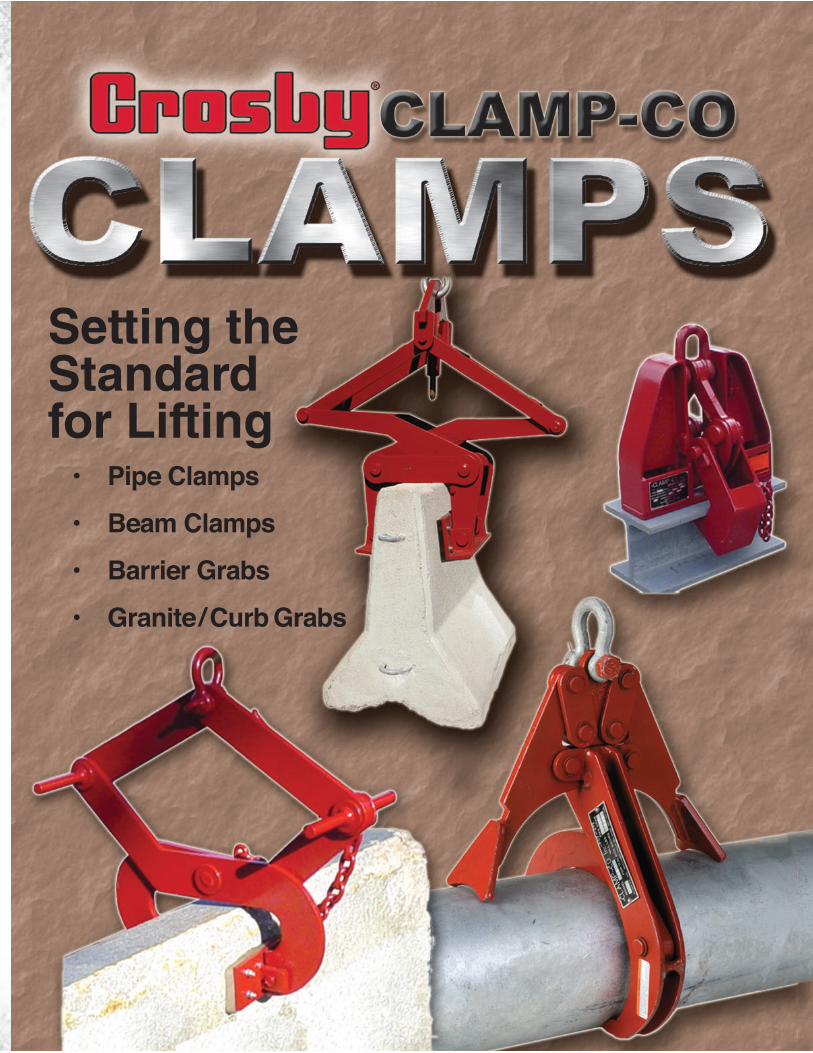
Setting the Standard for Lifting
Pipe Clamps
Beam Clamps
Barrier Grabs
Granite / Curb Grabs
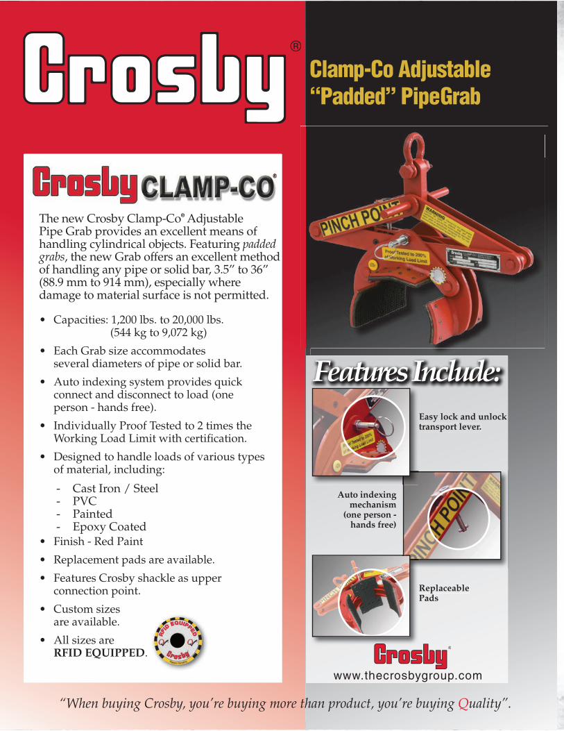
“When buying Crosby, you’re buying more than product, you’re buying Quality”.
Easy lock and unlock transport lever.
Auto indexing mechanism
(one person - hands free)
Replaceable Pads
Features Include:
www.thecrosbygroup.com
Clamp-Co Adjustable
“Padded” PipeGrab
The new Crosby Clamp-Co® Adjustable Pipe Grab provides an excellent means of handling cylindrical objects. Featuring padded grabs, the new Grab offers an excellent method of handling any pipe or solid bar, 3.5” to 36” (88.9 mm to 914 mm), especially where damage to material surface is not permitted.
• Capacities: 1,200 lbs. to 20,000 lbs. (544 kg to 9,072 kg)
• Each Grab size accommodates several diameters of pipe or solid bar.
• Auto indexing system provides quick connect and disconnect to load (one person - hands free).
• Individually Proof Tested to 2 times the Working Load Limit with certi�cation.
• Designed to handle loads of various types of material, including:
- Cast Iron / Steel - PVC - Painted - Epoxy Coated
• Finish - Red Paint
• Replacement pads are available.
• Features Crosby shackle as upper connection point.
• Custom sizes are available.
• All sizes are RFID EQUIPPED.

431
CR
OS
BY
® L
IFT
ING
CL
AM
PS
Copyright © 2016 The Crosby Group LLC All Rights Reserved
The new Crosby Clamp-Co® Adjustable Pipe Grab
provides an excellent means of handling cylindrical objects. Featuring padded grabs, the new Grab offers an excellent method of handling any pipe or solid bar, 3.5” to 36”, especially where damage to material surface is not permitted.
• Capacities: 1,200 lbs. to 20,000 lbs.• Each Grab size accommodates several diameters of pipe or solid bar.• Auto indexing system provides quick connect and disconnect to load
(one person - hands free).• Individually Proof Tested to 2 times the Working Load Limit with
• Designed to handle loads of various types of material, including:
- Cast Iron / Steel - PVC - Painted - Epoxy Coated
• Finish - Red Paint• Replacement pads are available.• Features Crosby shackle as upper connection point.• Custom sizes are available.• All sizes are RFID EQUIPPED.
* Maximum Proof Load is 2 times the Working Load Limit and design factor based on EN13155 and ASME B30.20.
CCPA
Padded Pipe Grab
Model No.
CCPAStock
No.
Working Load Limit*
(lbs.)
Weight Each (lbs.) Grip Width
Dimensions (in.)
A B C D E F
PA-5 2736000 1200 23
Locked Open
13.50 10.00 18.00
6.50 1.31 .50Min. Pipe
3.50”27.00 9.00 8.00
Max. Pipe 5.56”
23.00 9.00 14.75
PA-8 2736009 2000 75
Locked Open
23.50 15.50 27.75
10.00 1.69 .63Min. Pipe
5.56”40.50 14.50 14.00
Max. Pipe 8.81”
34.00 14.75 24.00
PA-14 2736018 4500 230
Locked Open
28.75 24.00 28.50
15.50 1.50 1.00Min. Pipe
8.81”46.00 22.50 13.50
Max. Pipe 14.00”
34.00 23.00 26.00
PA-22 2736027 10,000 496
Locked Open
42 36 42.5
20 2.5 1.5Min. Pipe14.00”
67.5 34 19
Max. Pipe 22.00”
52 36 40
PA-36 2736036 20,000 1250
LockedOpen
57.27 57.03 57.31
30.00 3.37 1.50Min. Pipe
24.00”92.02 52.38 26.98
Max. Pipe36.00”
66.36 55.03 53.24Locked Open
Min. Pipe Max. Pipe
Side View
CROSBY Clamp -Co® Padded Pipe Grab
432
CR
OS
BY
® L
IFT
ING
CL
AM
PS
Copyright © 2016 The Crosby Group LLC All Rights Reserved
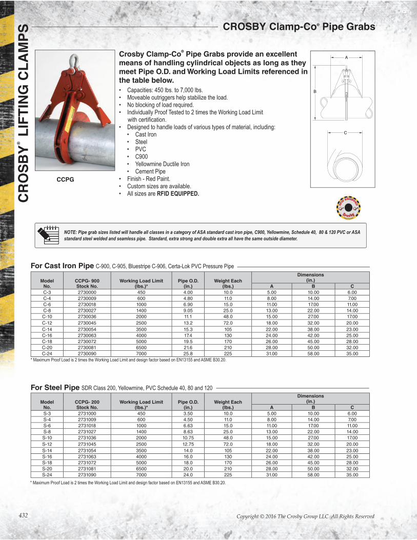
Crosby Clamp-Co® Pipe Grabs provide an excellent
means of handling cylindrical objects as long as they meet Pipe O.D. and Working Load Limits referenced in the table below.
• Capacities: 450 lbs. to 7,000 lbs.• Moveable outriggers help stabilize the load.• No blocking of load required.• Individually Proof Tested to 2 times the Working Load Limit
• Designed to handle loads of various types of material, including:• Cast Iron• Steel• PVC• C900• Yellowmine Ductile Iron• Cement Pipe
• Finish - Red Paint.• Custom sizes are available.• All sizes are RFID EQUIPPED.
CCPG
For Steel Pipe SDR Class 200, Yellowmine, PVC Schedule 40, 80 and 120
ModelNo.
CCPG- 900Stock No.
Working Load Limit(lbs.)*
Pipe O.D.(in.)
Weight Each(lbs.)
Dimensions(in.)
A B C
C-3 2730000 450 4.00 10.0 5.00 10.00 6.00
C-4 2730009 600 4.80 11.0 8.00 14.00 7.00
C-6 2730018 1000 6.90 15.0 11.00 17.00 11.00
C-8 2730027 1400 9.05 25.0 13.00 22.00 14.00
C-10 2730036 2000 11.1 48.0 15.00 27.00 17.00
C-12 2730045 2500 13.2 72.0 18.00 32.00 20.00
C-14 2730054 3500 15.3 105 22.00 38.00 23.00
C-16 2730063 4000 17.4 130 24.00 42.00 25.00
C-18 2730072 5000 19.5 170 26.00 45.00 28.00
C-20 2730081 6500 21.6 210 28.00 50.00 32.00
C-24 2730090 7000 25.8 225 31.00 58.00 35.00
ModelNo.
CCPG- 200Stock No.
Working Load Limit(lbs.)*
Pipe O.D.(in.)
Weight Each(lbs.)
Dimensions(in.)
A B C
S-3 2731000 450 3.50 10.0 5.00 10.00 6.00
S-4 2731009 600 4.50 11.0 8.00 14.00 7.00
S-6 2731018 1000 6.63 15.0 11.00 17.00 11.00
S-8 2731027 1400 8.63 25.0 13.00 22.00 14.00
S-10 2731036 2000 10.75 48.0 15.00 27.00 17.00
S-12 2731045 2500 12.75 72.0 18.00 32.00 20.00
S-14 2731054 3500 14.0 105 22.00 38.00 23.00
S-16 2731063 4000 16.0 130 24.00 42.00 25.00
S-18 2731072 5000 18.0 170 26.00 45.00 28.00
S-20 2731081 6500 20.0 210 28.00 50.00 32.00
S-24 2731090 7000 24.0 225 31.00 58.00 35.00
For Cast Iron Pipe C-900, C-905, Bluestripe C-906, Certa-Lok PVC Pressure Pipe
* Maximum Proof Load is 2 times the Working Load Limit and design factor based on EN13155 and ASME B30.20.
* Maximum Proof Load is 2 times the Working Load Limit and design factor based on EN13155 and ASME B30.20.
NOTE: Pipe grab sizes listed will handle all classes in a category of ASA standard cast iron pipe, C900, Yellowmine, Schedule 40, 80 & 120 PVC or ASA
standard steel welded and seamless pipe. Standard, extra strong and double extra all have the same outside diameter.
CROSBY Clamp-Co® Pipe Grabs
433
CR
OS
BY
® L
IFT
ING
CL
AM
PS
Copyright © 2016 The Crosby Group LLC All Rights Reserved
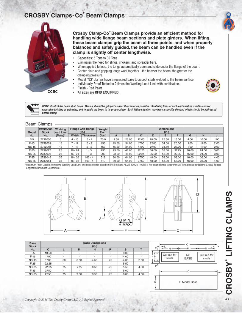
CCBC
Crosby Clamp-Co®Beam Clamps provide an efficient method for
handling wide flange beam sections and plate girders. When lifting, these beam clamps grip the beam at three points, and when properly balanced and safely guided, the beam can be handled even if the clamp is slightly off center lengthwise.
• Capacities: 5 Tons to 35 Tons• Eliminates the need for slings, chokers, and spreader bars.• • Center plate and gripping tongs work together - the heavier the beam, the greater the clamping pressure.• Model “NS” clamps have a recessed base to accept studs welded to the beam surface.• • Finish - Red Paint.• All sizes are RFID EQUIPPED.
BaseStock
No.
Base Dimensions(in.)
C L M N P S T
F-5 13.50 - - - - 3.00 -
F-15 17.00 - - - - 4.00 -
NS-15 17.00 .50 6.50 4.50 .75 4.00 2.50
F-25 22.25 - - - - 5.50 -
NS-25 22.25 .75 7.75 6.50 .75 5.50 4.00
F-35 27.50 - - - - 6.00 -
NS-35 27.50 .75 9.00 8.50 .75 6.00 4.50
ModelNo.
CCBC-500Stock
No.
WorkingLoad Limit
(Tons)*
Flange Grip Range(in.)
WeightEach(lbs.)
Dimensions(in.)
Width Thickness A B C D E F G H J
F-5 2732000 5 4 - 10 .5 - 1 70.0 9.50 26.00 12.00 20.00 25.50 16.00 4.00 10.00 1.00
F-15 2732009 15 7 - 17 .5 - 2 153 15.50 34.00 17.00 27.00 34.50 25.00 7.00 17.00 2.00
NS-15 2732018 15 7 - 17 .5 - 2 153 15.50 34.00 17.00 27.00 34.50 25.00 7.00 17.00 2.00
F-25 2732027 25 16 - 24 1 - 3 290 23.00 48.00 22.25 36.00 53.00 37.25 16.00 24.00 3.00
NS-25 2732036 25 16 - 24 1 - 3 290 23.00 48.00 22.25 36.00 53.00 37.25 16.00 24.00 3.00
F-35 2732045 35 16 - 36 1.63 - 4 519 30.00 64.00 27.50 48.00 58.00 53.00 16.00 36.00 4.00
NS-35 2732054 35 16 - 36 1.63 - 4 519 30.00 64.00 27.50 48.00 58.00 53.00 16.00 36.00 4.00
Beam Clamps
* Maximum Proof Load is 2 times the Working Load Limit and design factor based on EN13155 and ASME B30.20. NOTE: : For beam clamps larger than 35 Tons, please contact the Crosby Special Engineered Products Department.
NOTE: Control the beam at all times. Beams should be gripped as near the center as possible. Snubbing lines at each end must be used to control
before lifting.
CROSBY
Clamps-Co®
Beam Clamps
Copyright © 2016 The Crosby Group LLC All Rights Reserved434
CROSBY
®
LIFTING CLAMPS
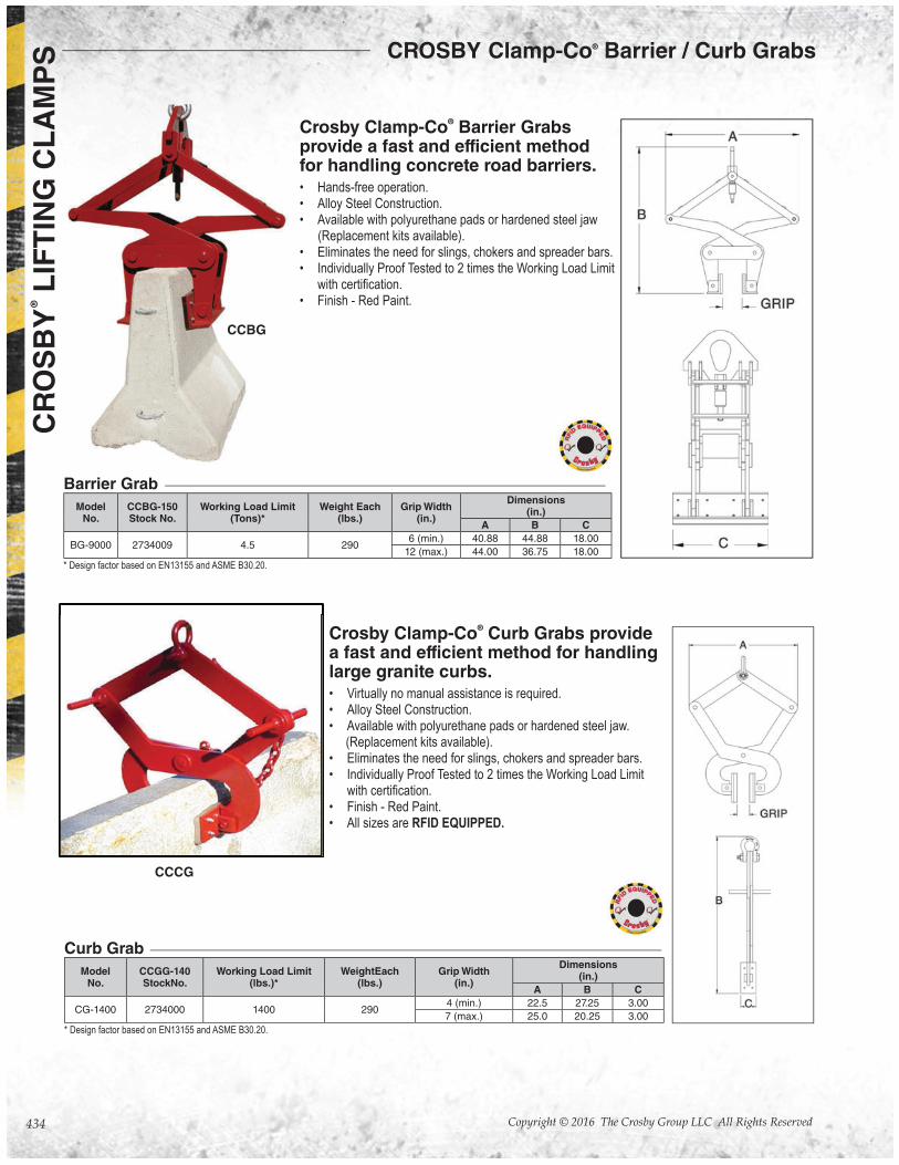
Crosby Clamp-Co® Barrier Grabs
provide a fast and efficient method for handling concrete road barriers.• Hands-free operation.• Alloy Steel Construction.• Available with polyurethane pads or hardened steel jaw (Replacement kits available).• Eliminates the need for slings, chokers and spreader bars.• Individually Proof Tested to 2 times the Working Load Limit
• Finish - Red Paint.
Crosby Clamp-Co® Curb Grabs provide
a fast and efficient method for handling large granite curbs.• Virtually no manual assistance is required.• Alloy Steel Construction.• Available with polyurethane pads or hardened steel jaw. (Replacement kits available).• Eliminates the need for slings, chokers and spreader bars.• Individually Proof Tested to 2 times the Working Load Limit
• Finish - Red Paint.• All sizes are RFID EQUIPPED.
CCBG
CCCG
ModelNo.
CCBG-150Stock No.
Working Load Limit(Tons)*
Weight Each(lbs.)
Grip Width(in.)
Dimensions(in.)
A B C
BG-9000 2734009 4.5 2906 (min.) 40.88 44.88 18.00
12 (max.) 44.00 36.75 18.00
ModelNo.
CCGG-140StockNo.
Working Load Limit(lbs.)*
WeightEach(lbs.)
Grip Width(in.)
Dimensions(in.)
A B C
CG-1400 2734000 1400 2904 (min.) 22.5 27.25 3.00
7 (max.) 25.0 20.25 3.00
Barrier Grab
Curb Grab
* Design factor based on EN13155 and ASME B30.20.
* Design factor based on EN13155 and ASME B30.20.
CROSBY Clamp-Co® Barrier / Curb Grabs
435
CR
OS
BY
® L
IFT
ING
CL
AM
PS
Copyright © 2016 The Crosby Group LLC All Rights Reserved
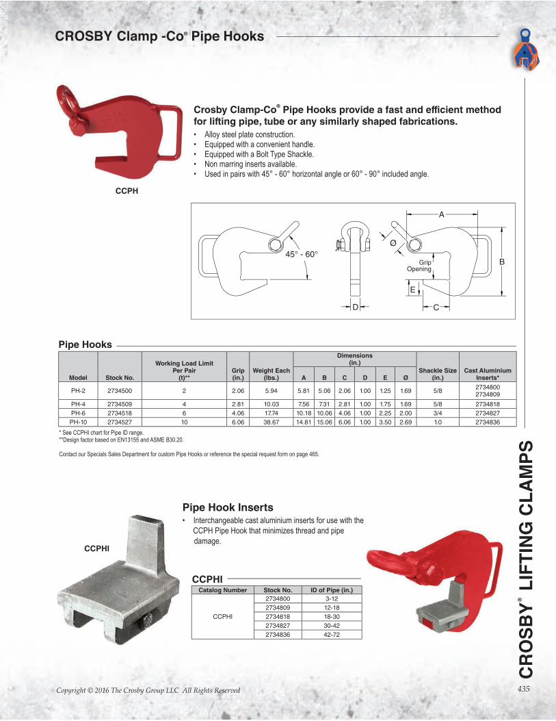
Crosby Clamp-Co® Pipe Hooks provide a fast and efficient method
for lifting pipe, tube or any similarly shaped fabrications.
• Alloy steel plate construction.• Equipped with a convenient handle.• Equipped with a Bolt Type Shackle.• Non marring inserts available.• Used in pairs with 45° - 60° horizontal angle or 60° - 90° included angle.
Pipe Hook Inserts• Interchangeable cast aluminium inserts for use with the
CCPH Pipe Hook that minimizes thread and pipe
damage.
CCPH
CCPHI
Model Stock No.
Working Load LimitPer Pair
(t)**Grip(in.)
Weight Each(lbs.)
Dimensions(in.)
Shackle Size(in.)
Cast Aluminium Inserts*A B C D E Ø
PH-2 2734500 2 2.06 5.94 5.81 5.06 2.06 1.00 1.25 1.69 5/82734800 2734809
PH-4 2734509 4 2.81 10.03 7.56 7.31 2.81 1.00 1.75 1.69 5/8 2734818
PH-6 2734518 6 4.06 17.74 10.18 10.06 4.06 1.00 2.25 2.00 3/4 2734827
PH-10 2734527 10 6.06 38.67 14.81 15.06 6.06 1.00 3.50 2.69 1.0 2734836
Pipe Hooks
* See CCPHI chart for Pipe ID range.**Design factor based on EN13155 and ASME B30.20.
Contact our Specials Sales Department for custom Pipe Hooks or reference the special request form on page 465.
Catalog Number Stock No. ID of Pipe (in.)
CCPHI
2734800 3-12
2734809 12-18
2734818 18-30
2734827 30-42
2734836 42-72
CCPHI
CROSBY Clamp -Co® Pipe Hooks

436
CR
OS
BY
®
LIF
TIN
G C
LA
MP
S NOTES