critical resolved shear stress for slip and twin...
TRANSCRIPT
Contents lists available at ScienceDirect
Materials Characterization
journal homepage: www.elsevier.com/locate/matchar
Critical resolved shear stress for slip and twin nucleation in single crystallineFeNiCoCrMn high entropy alloy
Wael Abuzaida,⁎, Huseyin Sehitoglub
a Department of Mechanical Engineering, American University of Sharjah, PO Box 26666, Sharjah, United Arab Emiratesb Department of Mechanical Science and Engineering, University of Illinois at Urbana-Champaign, 1206 W. Green St., Urbana, IL 61801, USA
A R T I C L E I N F O
Keywords:Slip activationTwin nucleationHigh entropy alloysHardeningDigital image correlationCritical resolved shear stress
A B S T R A C T
High entropy alloys is an emerging class of materials with superior mechanical properties down to cryogenictemperatures. At 77 K, and unlike traditional metallic alloys, an increase in strength, strain hardening rate, andductility has been reported. This enhancement in properties has been attributed to the activation of twinning asan additional deformation mechanism at low deformation temperatures. The tendency for the formation oftwinning and the hardening response dependence on crystal orientation has not been fully explored. This study isdedicated to explore the deformation evolution across several crystal orientations for the equiatomicFeNiCoCrMn high entropy alloy at room temperature (RT) and 77 K. The works aims to establish the criticalresolved shear stresses (CRSS) for slip and twinning and study the orientation and temperature dependence inthese magnitudes. The experimental results have revealed a strong temperature dependence in the CRSS for slip,increasing from 56 MPa at RT to 153 MPa at 77 K, with negligible orientation dependence. At 77 K, not allcrystal orientations developed twinning even at high levels of deformation. The lack of twinning has beenattributed to differences in the hardening response resulting in low stress levels below the twinning CRSS of153 MPa, as established in this work. No twinning was observed in any of the crystal orientations deformed atroom temperature, regardless of the level of hardening and the achieved stresses. Overall, the results discussed inthis work enhances our understanding of the local deformation response in single crystalline FeNiCoCrMn highentropy alloy, particularly the nucleation of slip, nucleation of twinning, and the effect of crystal orientation andloading temperature on these deformation mechanisms.
1. Introduction
Traditionally, strengthening of metallic alloys through solid solutionor precipitation hardening results in loss of ductility. High entropyalloys (HEA) is an emerging class of metallic alloys which deviates fromthe common trends by exhibiting high mechanical strength along withsignificant ductility [1–4]. The simultaneous enhancement in both ofthese properties extends to extreme cryogenic temperatures wheresuperior toughness measurements, relative to other metallic alloysunder similar condition, have been reported. The equiatomic FeNi-CoCrMn is one of the most commonly studied HEA due to itsremarkable properties at very low temperatures [2,5–12]. In general,the improvement in strength and ductility has been attributed to theactivation of twining, in addition to slip, at low temperatures and/orhigh strains. Most of the reported work, however, has been focused onpolycrystalline samples deformed to very high strains and postmortemSEM/TEM analysis [8,9]. The effect of different crystallographicorientations and the role played by grain boundaries can hinder our
ability to clearly understand the underlying deformation mechanisms.This work aims to experimentally investigate the deformation evolutionof FeNiCoCrMn single crystalline samples deformed at room (~298 K)and cryogenic temperatures (77 K). By collecting high resolution fullfield strain and orientation measurements, we pinpoint the criticalstresses for the activation of slip and twinning nucleation, highlight thedifferent deformation mechanisms at various loading levels, andinvestigate the hardening response in the presence of slip and/ortwinning. Overall, the work provides a deeper insight into the localdeformation mechanisms in FeNiCoCrMn HEA and enhances ourunderstanding of the role played by deformation twinning in improvingthe ductility at low temperatures.
The equiatomic FeNiCoCrMn HEA has a stable single phase withface-centered cubic (FCC) crystal structure. The deformation of thisalloy takes place primarily by slip on the {111}〈110〉 slip systems[5]. At low deformation temperatures (i.e., 77 K) and high strains(> 20%), several researchers have reported deformation twinning tooperate in addition to slip [2,7]. The strengthening effect of twinning is
http://dx.doi.org/10.1016/j.matchar.2017.05.014Received 17 March 2017; Received in revised form 9 May 2017; Accepted 10 May 2017
⁎ Corresponding author.E-mail address: [email protected] (W. Abuzaid).
Materials Characterization 129 (2017) 288–299
Available online 12 May 20171044-5803/ © 2017 Elsevier Inc. All rights reserved.
MARK
similar to what is typically observed in twinning induced plasticitysteels (TWIP steels) where twin-slip interaction results in strain hard-ening and consequently improved ductility by obstructing the forma-tion of necking [13–16]. The activation of slip/twinning is obviouslyorientation dependent and the initiation stresses will differ from crystalto crystal. The wealth of experimental work and the correspondinganalysis obtained from polycrystalline samples provide detailed analy-sis into the role played by twining in the deformation response ofFeNiCoCrMn. However, the effect of crystal orientation is smeared andit becomes very challenging to determine the critical stresses for slip/twinning nucleation [17]. For example, Laplanche has reported adiscrepancy between the critical resolved shear stress for twinning(CRSS) obtained from the critical twinning stress (obtained from apolycrystalline sample and using a Taylor factor of 3.06) and theore-tical values obtained from density functional theory [8]. With singlecrystalline samples and detailed electron backscattering diffraction(EBSD) orientation data and high resolution digital image correlation(DIC) strain measurements, the CRSS can be pinpointed withoutambiguity [18]. In addition, the tendency of different orientations toslip and/or twinning can be investigated at different stages of deforma-tion; thus providing means to assess the validity of Schmid law topredict slip and twinning for FeNiCoCrMn HEA.
The utilization of high resolution DIC and EBSD crystal orientationmeasurements, both covering the same region on the sample's surface,has proven to be very useful in determining the CRSS for the nucleationof slip or twinning in single crystalline metallic alloys. However, as thehigh resolution DIC measurements require reference and deformedimages to be captured in the optical microscope at high magnifications,the DIC measurements are limited to ~3% total plastic strain. Furtherdeformation will lead to significant surface distortions which wouldultimately hinder the ability to capture focused deformed images. As theemphasis in this work is on both, the critical nucleation stresses early inthe deformation, and the changes taking place at very high strains (e.g.,hardening and activation of twinning), there is a need to extend therange at which DIC measurements can be collected on the same sample.Through incremental loading steps followed by a sequence of polishingand re-establishing ex-situ DIC pattern, we were able to map out theentire response of each sample under consideration up to ~40% strain.The incremental full field data yields detailed information of deforma-tion between loading steps. By focusing on the same region of interest(sample edges utilized in this work for alignment), such analysis isadvantageous for capturing the factors influencing the hardeningresponse and the activation of twinning at potentially high strains aswill be shown in the current study.
In summary, this study is focused on studying the local deformationresponse of single crystalline FeNiCoCrMn HEA across a wide range ofcrystal orientations (〈111〉, 〈149〉, 〈122〉, and 〈123〉). Wepinpoint the activation of slip and twinning at different stages ofdeformation at room temperature (RT) and 77 K. We further asses thevalidity of the Schmid law to predict the activation of deformationtwinning based on the determined CRSS and the considered crystalorientations. Finally, and by capturing the underlying deformationmechanisms, we shed further insight into the interactions taking placeduring loading and their impact on the observed hardening responseand discuss the observations as they relate to the formation of localizedresponse (i.e., necking) and the formation of twinning.
2. Materials and Methods
Single crystal ingot of equiatomic FeNiCoCrMn was grown using theBridgman technique in He atmosphere. Homogenization of the crystalwas conducted at 1200 °C for 24 h followed by quenching in oil.Dogbone tension samples with 3 × 1.5 mm gauge section were electricdischarge machined from the ingot with the loading axis along the〈111〉, 〈149〉, 〈122〉, and 〈123〉 crystallographic directions.The crystal orientations were determined using EBSD as detailed in the
Appendix. Prior to loading, all samples were solution heat treated at1100 °C for 1 h, followed by oil quenching, and subsequent polishingusing SiC paper to prepare the surface for high resolution ex-situ DICmeasurements following the procedure detailed in [19]. Reference anddeformed images for full field strain measurements were collected usingoptical microscopy, ex-situ, at 5× magnification which corresponds toan imaging resolution of ~0.88 μm/pixel. A single image field of viewwas 1.41 × 1.05 mm. To cover the entire width of the sample with theselected high resolution setting, 3 images were captured across thewidth of the sample with ~30% overlap. Two rows of images werecollected to increase the size of the region monitored with highresolution DIC (region of interest ~3 × 2 mm). The DIC correlationswere conducted on the original images with results stitching followingthe procedure detailed in [20].
An Instron servo hydraulic load frame was used for tensile loading,in displacement control, with an average strain rate of 1.67−4 s−1.Sample alignment was achieved through a set of matching holes in theload frame grips and in both ends of the sample (see sample schematicin the Appendix). Prior to final clamping, alignment pins were insertedthrough the holes in the sample and grips. Each sample was incremen-tally loaded up to a total strain of ~40%. The specified loadingincrements varied from sample to sample and was adjusted dependingthe observed response and hardening behavior. At the end of eachloading increment, the samples were removed from the load frame tocollect deformation images in the optical microscope. To enablecontinued high resolution ex-situ DIC data collection, additional surfacepolishing was required to re-establish a good quality pattern after eachloading increment. Therefore, the reported DIC measurements repre-sent the incremental accumulation of strain between loading cycles andnot the total accumulated strains. Experiments were conducted at twodifferent temperatures, room temperature (RT ~ 298 K) and 77 Kwhere the specimen, grips, and extensometer (for data collection onlyand not for control) were all submersed in liquid nitrogen. For the RTexperiments, in-situ DIC measurements were collected during loadingfor the first increment only to help establish the critical stress for slipactivation. At 77 K, such measurements were not possible as thesamples were completely submersed in liquid nitrogen, thus leavingno access to image the surface in-situ.
3. Results and Analysis
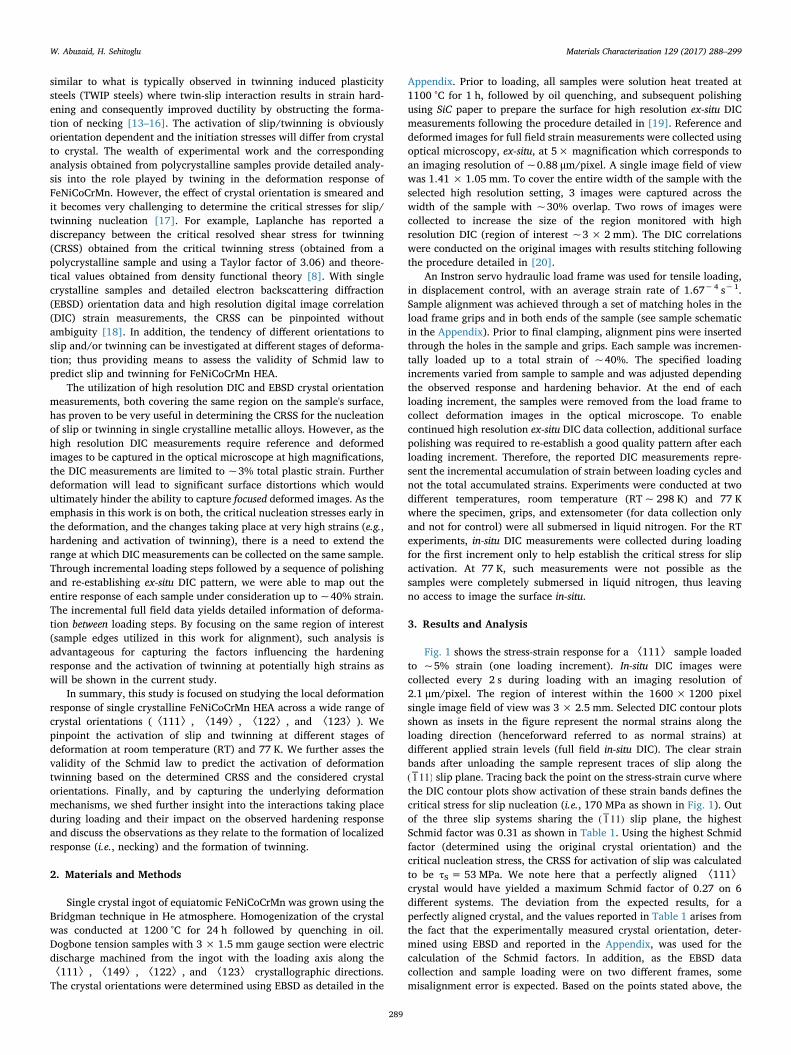
Fig. 1 shows the stress-strain response for a 〈111〉 sample loadedto ~5% strain (one loading increment). In-situ DIC images werecollected every 2 s during loading with an imaging resolution of2.1 μm/pixel. The region of interest within the 1600 × 1200 pixelsingle image field of view was 3 × 2.5 mm. Selected DIC contour plotsshown as insets in the figure represent the normal strains along theloading direction (henceforward referred to as normal strains) atdifferent applied strain levels (full field in-situ DIC). The clear strainbands after unloading the sample represent traces of slip along the( 1−11) slip plane. Tracing back the point on the stress-strain curve wherethe DIC contour plots show activation of these strain bands defines thecritical stress for slip nucleation (i.e., 170 MPa as shown in Fig. 1). Outof the three slip systems sharing the ( 1−11) slip plane, the highestSchmid factor was 0.31 as shown in Table 1. Using the highest Schmidfactor (determined using the original crystal orientation) and thecritical nucleation stress, the CRSS for activation of slip was calculatedto be τS = 53 MPa. We note here that a perfectly aligned 〈111〉crystal would have yielded a maximum Schmid factor of 0.27 on 6different systems. The deviation from the expected results, for aperfectly aligned crystal, and the values reported in Table 1 arises fromthe fact that the experimentally measured crystal orientation, deter-mined using EBSD and reported in the Appendix, was used for thecalculation of the Schmid factors. In addition, as the EBSD datacollection and sample loading were on two different frames, somemisalignment error is expected. Based on the points stated above, the
W. Abuzaid, H. Sehitoglu Materials Characterization 129 (2017) 288–299
289
observation of slip on the system with 0.31 Schmid factor and not onthe system with the maximum 0.32 Schmid factor is not of muchsignificance.
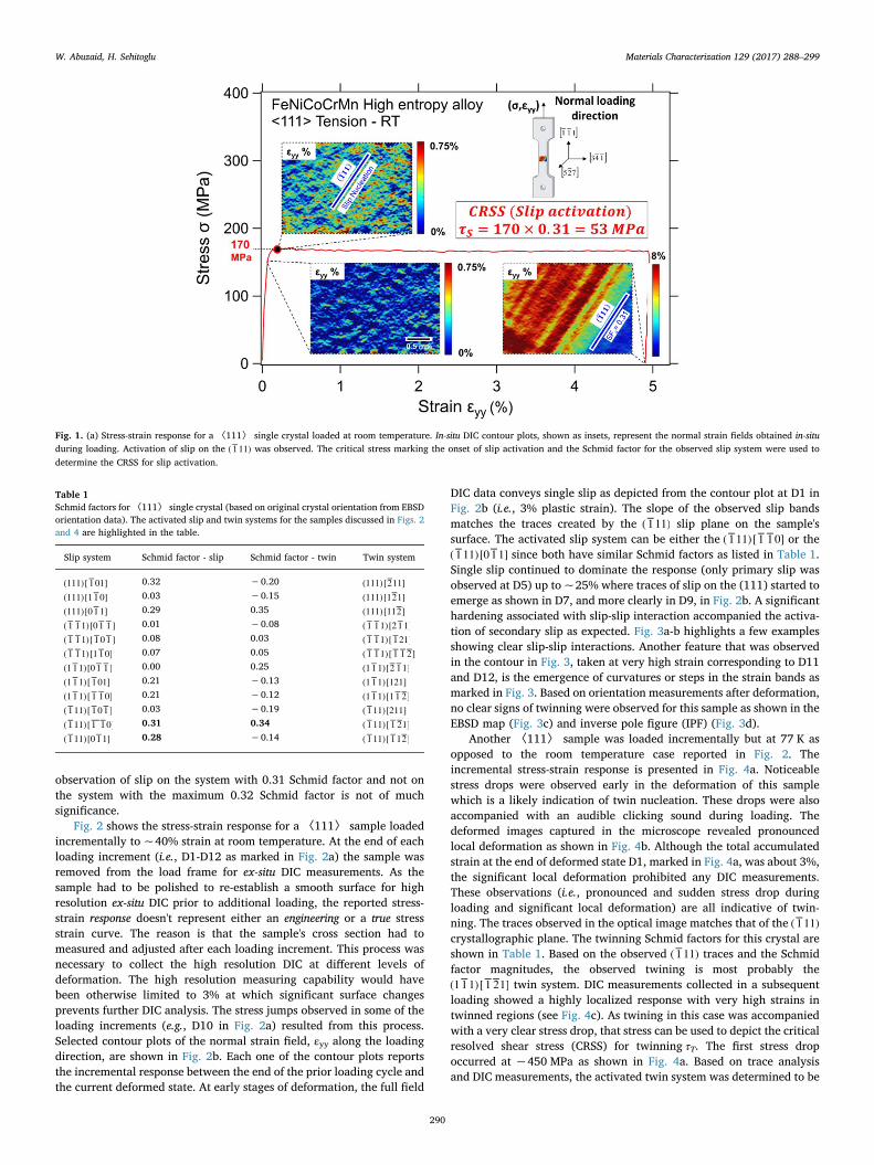
Fig. 2 shows the stress-strain response for a 〈111〉 sample loadedincrementally to ~40% strain at room temperature. At the end of eachloading increment (i.e., D1-D12 as marked in Fig. 2a) the sample wasremoved from the load frame for ex-situ DIC measurements. As thesample had to be polished to re-establish a smooth surface for highresolution ex-situ DIC prior to additional loading, the reported stress-strain response doesn't represent either an engineering or a true stressstrain curve. The reason is that the sample's cross section had tomeasured and adjusted after each loading increment. This process wasnecessary to collect the high resolution DIC at different levels ofdeformation. The high resolution measuring capability would havebeen otherwise limited to 3% at which significant surface changesprevents further DIC analysis. The stress jumps observed in some of theloading increments (e.g., D10 in Fig. 2a) resulted from this process.Selected contour plots of the normal strain field, εyy along the loadingdirection, are shown in Fig. 2b. Each one of the contour plots reportsthe incremental response between the end of the prior loading cycle andthe current deformed state. At early stages of deformation, the full field
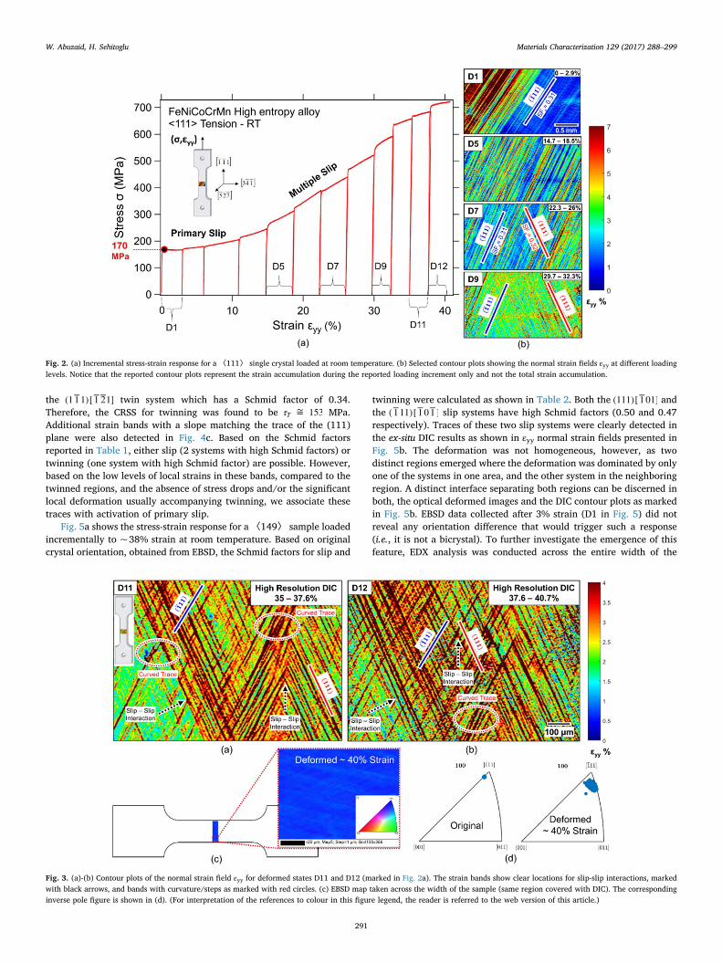
DIC data conveys single slip as depicted from the contour plot at D1 inFig. 2b (i.e., 3% plastic strain). The slope of the observed slip bandsmatches the traces created by the ( 1−11) slip plane on the sample'ssurface. The activated slip system can be either the ( 1−11)[ 1− 1−0] or the( 1−11)[0 1−1] since both have similar Schmid factors as listed in Table 1.Single slip continued to dominate the response (only primary slip wasobserved at D5) up to ~25% where traces of slip on the (111) started toemerge as shown in D7, and more clearly in D9, in Fig. 2b. A significanthardening associated with slip-slip interaction accompanied the activa-tion of secondary slip as expected. Fig. 3a-b highlights a few examplesshowing clear slip-slip interactions. Another feature that was observedin the contour in Fig. 3, taken at very high strain corresponding to D11and D12, is the emergence of curvatures or steps in the strain bands asmarked in Fig. 3. Based on orientation measurements after deformation,no clear signs of twinning were observed for this sample as shown in theEBSD map (Fig. 3c) and inverse pole figure (IPF) (Fig. 3d).
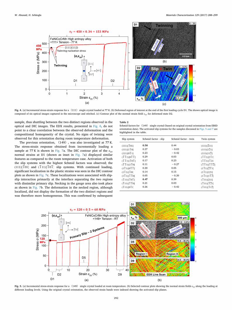
Another 〈111〉 sample was loaded incrementally but at 77 K asopposed to the room temperature case reported in Fig. 2. Theincremental stress-strain response is presented in Fig. 4a. Noticeablestress drops were observed early in the deformation of this samplewhich is a likely indication of twin nucleation. These drops were alsoaccompanied with an audible clicking sound during loading. Thedeformed images captured in the microscope revealed pronouncedlocal deformation as shown in Fig. 4b. Although the total accumulatedstrain at the end of deformed state D1, marked in Fig. 4a, was about 3%,the significant local deformation prohibited any DIC measurements.These observations (i.e., pronounced and sudden stress drop duringloading and significant local deformation) are all indicative of twin-ning. The traces observed in the optical image matches that of the ( 1−11)crystallographic plane. The twinning Schmid factors for this crystal areshown in Table 1. Based on the observed ( 1−11) traces and the Schmidfactor magnitudes, the observed twining is most probably the(1 1−1)[ 1−2−1] twin system. DIC measurements collected in a subsequentloading showed a highly localized response with very high strains intwinned regions (see Fig. 4c). As twining in this case was accompaniedwith a very clear stress drop, that stress can be used to depict the criticalresolved shear stress (CRSS) for twinning τT. The first stress dropoccurred at ~450 MPa as shown in Fig. 4a. Based on trace analysisand DIC measurements, the activated twin system was determined to be
Fig. 1. (a) Stress-strain response for a 〈111〉 single crystal loaded at room temperature. In-situ DIC contour plots, shown as insets, represent the normal strain fields obtained in-situduring loading. Activation of slip on the ( 1−11) was observed. The critical stress marking the onset of slip activation and the Schmid factor for the observed slip system were used todetermine the CRSS for slip activation.
Table 1Schmid factors for〈111〉 single crystal (based on original crystal orientation from EBSDorientation data). The activated slip and twin systems for the samples discussed in Figs. 2and 4 are highlighted in the table.
Slip system Schmid factor - slip Schmid factor - twin Twin system
(111)[ 1−01] 0.32 −0.20 (111)[2−11](111)[1 1−0] 0.03 −0.15 (111)[12−1](111)[0 1−1] 0.29 0.35 (111)[112−]( 1− 1−1)[0 1− 1−] 0.01 −0.08 ( 1− 1−1)[2 1−1]( 1− 1−1)[ 1−0 1−] 0.08 0.03 ( 1− 1−1)[ 1−21]( 1− 1−1)[1 1−0] 0.07 0.05 ( 1− 1−1)[ 1− 1−2−](1 1−1)[0 1− 1−] 0.00 0.25 (1 1−1)[2−1−1](1 1−1)[ 1−01] 0.21 −0.13 (1 1−1)[121](1 1−1)[ 1− 1−0] 0.21 −0.12 (1 1−1)[1 1−2−]( 1−11)[ 1−0 1−] 0.03 −0.19 ( 1−11)[211]
−( 1−11)[1 1−0] 0.31 0.34 ( 1−11)[ 1−2−1]( 1−11)[0 1−1] 0.28 −0.14 ( 1−11)[ 1−12−]
W. Abuzaid, H. Sehitoglu Materials Characterization 129 (2017) 288–299
290
the (1 1−1)[ 1−2−1] twin system which has a Schmid factor of 0.34.Therefore, the CRSS for twinning was found to be τ = 153∼
T MPa.Additional strain bands with a slope matching the trace of the (111)plane were also detected in Fig. 4c. Based on the Schmid factorsreported in Table 1, either slip (2 systems with high Schmid factors) ortwinning (one system with high Schmid factor) are possible. However,based on the low levels of local strains in these bands, compared to thetwinned regions, and the absence of stress drops and/or the significantlocal deformation usually accompanying twinning, we associate thesetraces with activation of primary slip.
Fig. 5a shows the stress-strain response for a〈149〉 sample loadedincrementally to ~38% strain at room temperature. Based on originalcrystal orientation, obtained from EBSD, the Schmid factors for slip and
twinning were calculated as shown in Table 2. Both the (111)[ 1−01] andthe ( 1−11)[ 1−0 1−] slip systems have high Schmid factors (0.50 and 0.47respectively). Traces of these two slip systems were clearly detected inthe ex-situ DIC results as shown in εyy normal strain fields presented inFig. 5b. The deformation was not homogeneous, however, as twodistinct regions emerged where the deformation was dominated by onlyone of the systems in one area, and the other system in the neighboringregion. A distinct interface separating both regions can be discerned inboth, the optical deformed images and the DIC contour plots as markedin Fig. 5b. EBSD data collected after 3% strain (D1 in Fig. 5) did notreveal any orientation difference that would trigger such a response(i.e., it is not a bicrystal). To further investigate the emergence of thisfeature, EDX analysis was conducted across the entire width of the
Fig. 2. (a) Incremental stress-strain response for a 〈111〉 single crystal loaded at room temperature. (b) Selected contour plots showing the normal strain fields εyy at different loadinglevels. Notice that the reported contour plots represent the strain accumulation during the reported loading increment only and not the total strain accumulation.
Fig. 3. (a)-(b) Contour plots of the normal strain field εyy for deformed states D11 and D12 (marked in Fig. 2a). The strain bands show clear locations for slip-slip interactions, markedwith black arrows, and bands with curvature/steps as marked with red circles. (c) EBSD map taken across the width of the sample (same region covered with DIC). The correspondinginverse pole figure is shown in (d). (For interpretation of the references to colour in this figure legend, the reader is referred to the web version of this article.)
W. Abuzaid, H. Sehitoglu Materials Characterization 129 (2017) 288–299
291
sample, thus shuttling between the two distinct regions observed in theoptical and DIC images. The EDX results, presented in Fig. 6, do notpoint to a clear correlation between the observed deformation and thecompositional homogeneity of the crystal. No signs of twining wereobserved for this orientation during room temperature deformation.
The previous orientation, 〈149〉, was also investigated at 77 K.The stress-strain response obtained from incrementally loading asample at 77 K is shown in Fig. 7a. The DIC contour plot of the εyynormal strains at D1 (shown as inset in Fig. 7a) displayed similarfeatures as compared to the room temperature case. Activation of boththe slip systems with the highest Schmid factors was observed; the(111)[ 1−01] and ( 1−11)[ 1−0 1−] slip systems. With continued loading,significant localization in the plastic strains was seen in the DIC contourplots as shown in Fig. 7c. These localizations were associated with slip-slip interaction primarily at the interface separating the two regionswith dissimilar primary slip. Necking in the gauge area also took placeas shown in Fig. 7b. The deformation in the necked region, althoughlocalized, did not display the formation of the two distinct regions andwas therefore more homogeneous. This was confirmed by subsequent
Fig. 4. (a) Incremental stress-strain response for a〈111〉 single crystal loaded at 77 K. (b) Deformed region of interest at the end of the first loading cycle D1. The shown optical image iscomposed of six optical images captured in the microscope and stitched. (c) Contour plot of the normal strain field εyy for deformed state D2.
Fig. 5. (a) Incremental stress-strain response for a 〈149〉 single crystal loaded at room temperature. (b) Selected contour plots showing the normal strain fields εyy along the loading atdifferent loading levels. Using the original crystal orientation, the observed strain bands were indexed showing the activated slip planes.
Table 2Schmid factors for〈149〉 single crystal (based on original crystal orientation from EBSDorientation data). The activated slip systems for the samples discussed in Figs. 5 and 7 arehighlighted in the table.
Slip system Schmid factor - slip Schmid factor - twin Twin system
(111)[ 1−01] 0.50 0.44 (111)[2−11](111)[1 1−0] 0.27 −0.03 (111)[12−1](111)[0 1−1] 0.23 −0.42 (111)[112−]( 1− 1−1)[0 1− 1−] 0.29 0.03 ( 1− 1−1)[2 1−1]( 1− 1−1)[ 1−0 1−] 0.17 0.23 ( 1− 1−1)[ 1−21]( 1− 1−1)[1 1−0] 0.11 −0.27 ( 1− 1−1)[ 1− 1−2−](1 1−1)[0 1− 1−] 0.20 0.05 (1 1−1)[2−1−1](1 1−1)[ 1−01] 0.14 0.15 (1 1−1)[121](1 1−1)[ 1− 1−0] 0.05 −0.20 (1 1−1)[1 1−2−]( 1−11)[ 1−0 1−] 0.47 0.39 ( 1−11)[211]( 1−11)[ 1− 1−0] 0.21 0.03 ( 1−11)[ 1−2−1]( 1−11)[0 1−1] 0.26 −0.42 ( 1−11)[ 1−12−]
W. Abuzaid, H. Sehitoglu Materials Characterization 129 (2017) 288–299
292
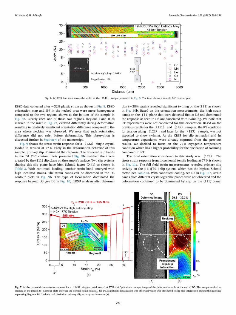
EBSD data collected after ~32% plastic strain as shown in Fig. 8. EBSDorientation map and IPF in the necked area were more homogenouscompared to the two regions shown at the bottom of the sample inFig. 8b. Clearly each one of these two regions, Regions I and II asmarked in the inset in Fig. 7a, evolved differently during deformationresulting in relatively significant orientation difference compared to thearea where necking was observed. We note that such orientationdifference did not exist before deformation. This observation isdiscussed further in Section 4 of the manuscript.
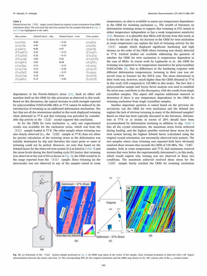
Fig. 9 shows the stress-strain response for a 〈122〉 single crystalloaded in tension at 77 K. Early in the deformation behavior of thissample, primary slip dominated the response. The observed slip bandsin the D1 DIC contour plots presented Fig. 9b matched the tracescreated by the (111) slip plane on the sample's surface. Two slip systemssharing this slip plane have high Schmid factor (0.41) as shown inTable 3. With continued loading, another strain band emerged withhigh localized strains. The strain bands can be discerned in the D3contour plots in Fig. 9b. This type of localization dominated theresponse beyond D3 (see D6 in Fig. 10). EBSD analysis after deforma-
tion (~38% strain) revealed significant twining on the (1 1−1) as shownin Fig. 10b. Based on the orientation measurements, the high strainbands on the (1 1−1) plane that were detected first at D3 and dominatedthe response as seen in D6 are associated with twinning. We note thatRT experiments were not conducted for this orientation. Based on theprevious results for the 〈111〉 and 〈149〉 samples, the RT conditionfor tension along 〈122〉, and later for the 〈123〉 sample, was notexpected to show twining. As the CRSS for slip activation and itstemperature dependence were already captured from the previousresults, we decided to focus on the 77 K cryogenic temperaturecondition which has a higher probability for the nucleation of twinningcompared to RT.
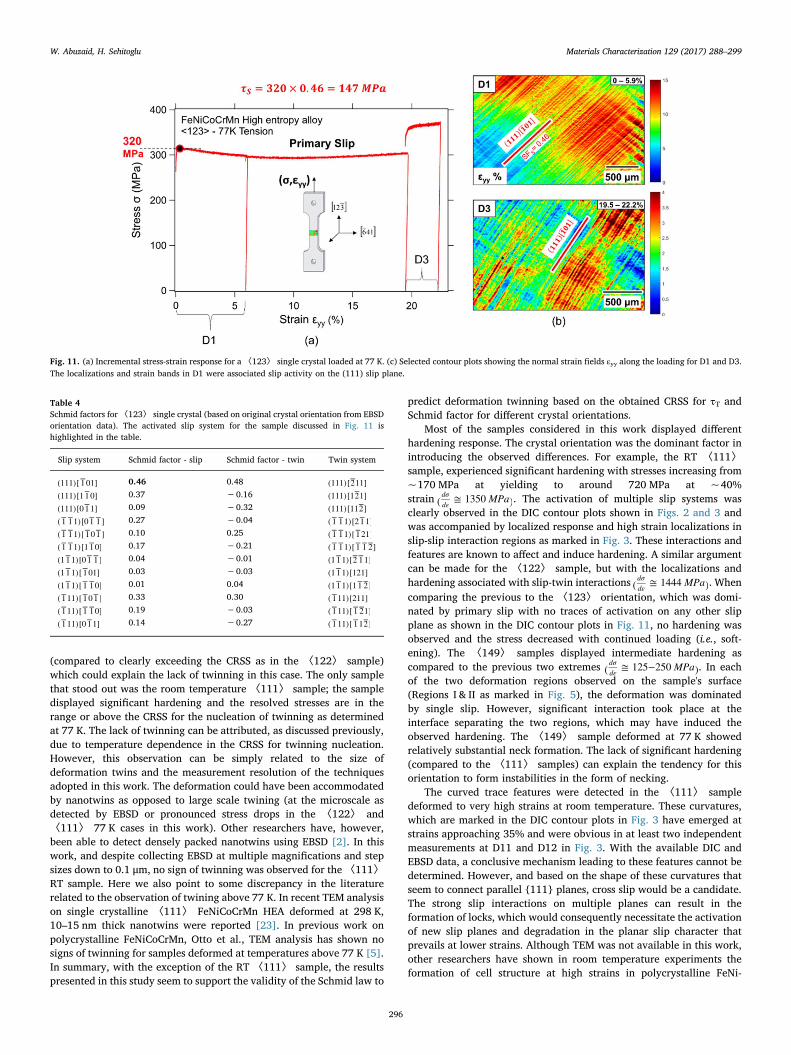
The final orientation considered in this study was 〈123〉. Thestress-strain response from incremental tensile loading at 77 K is shownin Fig. 11a. The full field strain measurements revealed primary slipactivity on the (111)[ 1−01] slip system, which has the highest Schmidfactor (see Table 4). With continued loading, see D3 in Fig. 11b, strainbands from different crystallographic planes were not observed and thedeformation continued to be dominated by slip on the (111) plane.
Fig. 6. (a) EDX line scan across the width of the 〈149〉 sample presented in Fig. 5. The inset shows a sample DIC contour plot.
Fig. 7. (a) Incremental stress-strain response for a 〈149〉 single crystal loaded at 77 K. (b) Optical microscope image of the deformed sample at the end of D5. The sample necked asmarked in the image. (c) Contour plots showing the normal strain fields εyy for D5. Significant localization was observed which was attributed to slip-slip interaction around the interfaceseparating Regions I & II which had dissimilar primary slip activity as shown in (a).
W. Abuzaid, H. Sehitoglu Materials Characterization 129 (2017) 288–299
293
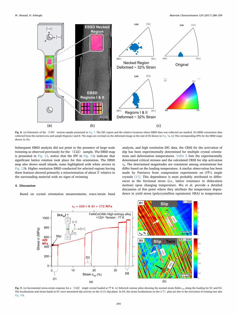
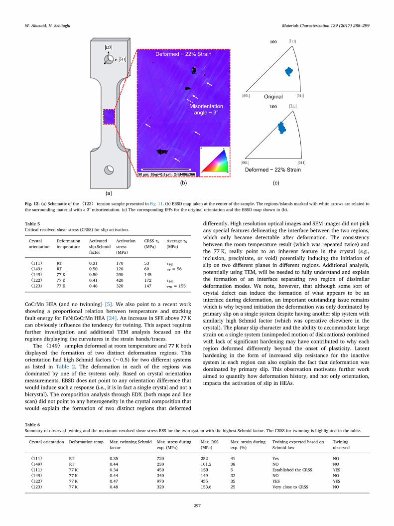
Subsequent EBSD analysis did not point to the presence of large scaletwinning as observed previously for the〈122〉 sample. The EBSD mapis presented in Fig. 12, notice that the IPF in Fig. 12c indicate thatsignificant lattice rotation took place for this orientation. The EBSDmap also shows small islands, some highlighted with white arrows inFig. 12b. Higher resolution EBSD conducted for selected regions havingthese features showed primarily a misorientation of about 3° relative tothe surrounding material with no signs of twinning
4. Discussion
Based on crystal orientation measurements, trace/strain band
analysis, and high resolution DIC data, the CRSS for the activation ofslip has been experimentally determined for multiple crystal orienta-tions and deformation temperatures. Table 5 lists the experimentallydetermined critical stresses and the calculated CRSS for slip activationτS. The determined magnitudes are consistent among orientations butdiffer based on the loading temperature. A similar observation has beenmade by Patriarca from compression experiments on [59−1] singlecrystals [17]. This dependence is most probably attributed to differ-ences in the frictional stress (i.e., lattice resistance to dislocationmotion) upon changing temperature. Wu et al. provide a detaileddiscussion of this point where they attribute the temperature depen-dence in yield stress (polycrystalline equiatomic HEA) to temperature
Fig. 8. (a) Schematic of the 〈149〉 tension sample presented in Fig. 7. The DIC region and the relative locations where EBSD data was collected are marked. (b) EBSD orientation datacollected from the necked area and sample Regions I and II. The maps are overlaid on the deformed image at the end of D5 shown in Fig. 7a. (c) The corresponding IPFs for the EBSD mapsshown in (b).
Fig. 9. (a) Incremental stress-strain response for a 〈122〉 single crystal loaded at 77 K. (c) Selected contour plots showing the normal strain fields εyy along the loading for D1 and D3.The localizations and strain bands in D1 were associated slip activity on the (111) slip plane. In D3, the strain localizations on the (1 1−1) plan are due to the activation of twining (see alsoFig. 10).
W. Abuzaid, H. Sehitoglu Materials Characterization 129 (2017) 288–299
294
dependence in the Peierls–Nabarro stress [21]. Such an effect willmanifest itself on the CRSS for slip activation as observed in this work.Based on this discussion, the typical increase in yield strength reportedfor polycrystalline FeNiCoCrMn HEA at 77 K cannot be induced by theintroduction of twinning as an additional deformation mechanism. Thefact that not all the orientations studied in this work displayed twinningwhen deformed at 77 K and that twinning was preceded by consider-able slip activity in the 〈122〉 crystal supports this conclusion.
As for the CRSS for twin nucleation τT, only one experimentalresults was available for the nucleation stress, which was from the〈111〉 sample loaded at 77 K. The other sample where twinning wasalso clearly observed (i.e., the 〈122〉 sample at 77 K) does not allowfor precise calculation of the twinning stress as the deformation wasinitially dominated by slip and therefore the exact point or onset oftwinning could not be picked. However, we note that based on theSchmid factor for the observed twin system (0.2 as listed in Table 3) andthe stress levels during the third loading cycle D3 (notice that twinningwas observed at the end of D3 as shown in Fig. 9), the CRSS would be inthe range reported from the 〈111〉 sample. Since twinning (at themicroscale) was not observed in any of the samples tested at room
temperature, no data is available to assess any temperature dependencein the CRSS for twinning nucleation τT. The wealth of literature ondeformation twinning seems to support that twinning in FCC metals iseither temperature independent or has a weak temperature sensitivity[22]. However, it is plausible that HEAs will deviate from this trend, asit does for the case of slip. An increase in the CRSS for twin nucleationat room temperature can explain the lack of twinning activity for the〈111〉 sample which displayed significant hardening and highstresses on the order of the CRSS where twinning was clearly detectedat 77 K. Limited studies are available addressing the question ofwhether the CRSS for twin nucleation is temperature dependent inthe case of HEAs. In recent work by Laplanche et al., the CRSS fortwinning was reported to be temperature insensitive for polycrystallineFeNiCoCrMn [8]. Due to differences in the hardening response withdifferent deformation temperatures, twinning in their case was ob-served close to fracture for the 293 K case. The stress determined intheir work was, however, much higher than the CRSS obtained at 77 Kin this work (235 compared to 155 MPa in this study). The fact that apolycrystalline sample and Taylor factor analysis was used to establishthe stress may contribute to the discrepancy with the results from singlecrystalline samples. This aspect still requires additional research todetermine if there is any temperature dependence in the CRSS fortwinning nucleation from single crystalline samples.
Another important question is raised based on the previous ob-servations; can the CRSS for twin nucleation and the Schmid lawexplain the lack of obvious twinning in many of the deformed samples?Based on what has been typically discussed in the literature, deforma-tion at 77 K or at strains in excess of 20% should have beenaccommodated by deformation twinning in addition to slip. Table 6lists all the crystal orientations, the maximum stress levels achievedduring loading, and the highest possible resolved shear stress for thetwin system having the highest Schmid factor (calculated using theoriginal crystal orientation, not necessarily observed twin system). Thetwo samples where clear twinning was reported both have obviouslyresolved shear stresses that exceeds the CRSS of 155 MPa. The 〈149〉samples, both at room temperature and 77 K, had maximum resolvedstresses that were below the experimentally determined τT in this study,which would explain why twining was not observed in these twoconditions. The maximum achieved resolved shear stress for the〈123〉 sample barely reached the CRSS for twinning nucleation
Table 3Schmid factors for〈122〉 single crystal (based on original crystal orientation from EBSDorientation data). The activated slip and twin systems for the samples discussed in Figs. 9and 10 are highlighted in the table.
Slip system Schmid factor - slip Schmid factor - twin Twin system
(111)[ 1−01] 0.41 −0.23 (111)[2−11](111)[1 1−0] 0.00 −0.24 (111)[12−1](111)[0 1−1] 0.41 0.47 (111)[112−]( 1− 1−1)[0 1− 1−] 0.23 −0.13 ( 1− 1−1)[2 1−1]( 1− 1−1)[ 1−0 1−] 0.22 −0.13 ( 1− 1−1)[ 1−21]( 1− 1−1)[1 1−0] 0.00 0.26 ( 1− 1−1)[ 1− 1−2−](1 1−1)[0 1− 1−] 0.05 0.19 (1 1−1)[2−1−1](1 1−1)[ 1−01] 0.14 −0.13 (1 1−1)[121](1 1−1)[ 1− 1−0] 0.19 −0.05 (1 1−1)[1 1−2−]( 1−11)[ 1−0 1−] 0.04 −0.13 ( 1−11)[211]( 1−11)[ 1− 1−0] 0.18 0.18 ( 1−11)[ 1−2−1]( 1−11)[0 1−1] 0.14 −0.05 ( 1−11)[ 1−12−]
Fig. 10. (a) Schematic of the 〈122〉 tension sample presented in Fig. 9. (b) EBSD map taken at the center of the sample. Clear twinning formation is observed with a 60° degreemisorientation between the matrix and twin. (c) The corresponding IPFs for the original orientation and the EBSD map shown in (b). DIC contour plot of the εyy normal strains.
W. Abuzaid, H. Sehitoglu Materials Characterization 129 (2017) 288–299
295
(compared to clearly exceeding the CRSS as in the 〈122〉 sample)which could explain the lack of twinning in this case. The only samplethat stood out was the room temperature 〈111〉 sample; the sampledisplayed significant hardening and the resolved stresses are in therange or above the CRSS for the nucleation of twinning as determinedat 77 K. The lack of twinning can be attributed, as discussed previously,due to temperature dependence in the CRSS for twinning nucleation.However, this observation can be simply related to the size ofdeformation twins and the measurement resolution of the techniquesadopted in this work. The deformation could have been accommodatedby nanotwins as opposed to large scale twining (at the microscale asdetected by EBSD or pronounced stress drops in the 〈122〉 and〈111〉 77 K cases in this work). Other researchers have, however,been able to detect densely packed nanotwins using EBSD [2]. In thiswork, and despite collecting EBSD at multiple magnifications and stepsizes down to 0.1 μm, no sign of twinning was observed for the 〈111〉RT sample. Here we also point to some discrepancy in the literaturerelated to the observation of twining above 77 K. In recent TEM analysison single crystalline 〈111〉 FeNiCoCrMn HEA deformed at 298 K,10–15 nm thick nanotwins were reported [23]. In previous work onpolycrystalline FeNiCoCrMn, Otto et al., TEM analysis has shown nosigns of twinning for samples deformed at temperatures above 77 K [5].In summary, with the exception of the RT 〈111〉 sample, the resultspresented in this study seem to support the validity of the Schmid law to
predict deformation twinning based on the obtained CRSS for τT andSchmid factor for different crystal orientations.
Most of the samples considered in this work displayed differenthardening response. The crystal orientation was the dominant factor inintroducing the observed differences. For example, the RT 〈111〉sample, experienced significant hardening with stresses increasing from~170 MPa at yielding to around 720 MPa at ~40%strain MPa( ≅ 1350 )
dσdε
. The activation of multiple slip systems wasclearly observed in the DIC contour plots shown in Figs. 2 and 3 andwas accompanied by localized response and high strain localizations inslip-slip interaction regions as marked in Fig. 3. These interactions andfeatures are known to affect and induce hardening. A similar argumentcan be made for the 〈122〉 sample, but with the localizations andhardening associated with slip-twin interactions MPa( ≅ 1444 )
dσdε
. Whencomparing the previous to the 〈123〉 orientation, which was domi-nated by primary slip with no traces of activation on any other slipplane as shown in the DIC contour plots in Fig. 11, no hardening wasobserved and the stress decreased with continued loading (i.e., soft-ening). The 〈149〉 samples displayed intermediate hardening ascompared to the previous two extremes MPa( ≅ 125−250 )
dσdε
. In eachof the two deformation regions observed on the sample's surface(Regions I & II as marked in Fig. 5), the deformation was dominatedby single slip. However, significant interaction took place at theinterface separating the two regions, which may have induced theobserved hardening. The 〈149〉 sample deformed at 77 K showedrelatively substantial neck formation. The lack of significant hardening(compared to the 〈111〉 samples) can explain the tendency for thisorientation to form instabilities in the form of necking.
The curved trace features were detected in the 〈111〉 sampledeformed to very high strains at room temperature. These curvatures,which are marked in the DIC contour plots in Fig. 3 have emerged atstrains approaching 35% and were obvious in at least two independentmeasurements at D11 and D12 in Fig. 3. With the available DIC andEBSD data, a conclusive mechanism leading to these features cannot bedetermined. However, and based on the shape of these curvatures thatseem to connect parallel {111} planes, cross slip would be a candidate.The strong slip interactions on multiple planes can result in theformation of locks, which would consequently necessitate the activationof new slip planes and degradation in the planar slip character thatprevails at lower strains. Although TEM was not available in this work,other researchers have shown in room temperature experiments theformation of cell structure at high strains in polycrystalline FeNi-
Fig. 11. (a) Incremental stress-strain response for a 〈123〉 single crystal loaded at 77 K. (c) Selected contour plots showing the normal strain fields εyy along the loading for D1 and D3.The localizations and strain bands in D1 were associated slip activity on the (111) slip plane.
Table 4Schmid factors for〈123〉 single crystal (based on original crystal orientation from EBSDorientation data). The activated slip system for the sample discussed in Fig. 11 ishighlighted in the table.
Slip system Schmid factor - slip Schmid factor - twin Twin system
(111)[ 1−01] 0.46 0.48 (111)[2−11](111)[1 1−0] 0.37 −0.16 (111)[12−1](111)[0 1−1] 0.09 −0.32 (111)[112−]( 1− 1−1)[0 1− 1−] 0.27 −0.04 ( 1− 1−1)[2 1−1]( 1− 1−1)[ 1−0 1−] 0.10 0.25 ( 1− 1−1)[ 1−21]( 1− 1−1)[1 1−0] 0.17 −0.21 ( 1− 1−1)[ 1− 1−2−](1 1−1)[0 1− 1−] 0.04 −0.01 (1 1−1)[2−1−1](1 1−1)[ 1−01] 0.03 −0.03 (1 1−1)[121](1 1−1)[ 1− 1−0] 0.01 0.04 (1 1−1)[1 1−2−]( 1−11)[ 1−0 1−] 0.33 0.30 ( 1−11)[211]( 1−11)[ 1− 1−0] 0.19 −0.03 ( 1−11)[ 1−2−1]( 1−11)[0 1−1] 0.14 −0.27 ( 1−11)[ 1−12−]
W. Abuzaid, H. Sehitoglu Materials Characterization 129 (2017) 288–299
296
CoCrMn HEA (and no twinning) [5]. We also point to a recent workshowing a proportional relation between temperature and stackingfault energy for FeNiCoCrMn HEA [24]. An increase in SFE above 77 Kcan obviously influence the tendency for twining. This aspect requiresfurther investigation and additional TEM analysis focused on theregions displaying the curvatures in the strain bands/traces.
The 〈149〉 samples deformed at room temperature and 77 K bothdisplayed the formation of two distinct deformation regions. Thisorientation had high Schmid factors (~0.5) for two different systemsas listed in Table 2. The deformation in each of the regions wasdominated by one of the systems only. Based on crystal orientationmeasurements, EBSD does not point to any orientation difference thatwould induce such a response (i.e., it is in fact a single crystal and not abicrystal). The composition analysis through EDX (both maps and linescan) did not point to any heterogeneity in the crystal composition thatwould explain the formation of two distinct regions that deformed
differently. High resolution optical images and SEM images did not pickany special features delineating the interface between the two regions,which only became detectable after deformation. The consistencybetween the room temperature result (which was repeated twice) andthe 77 K, really point to an inherent feature in the crystal (e.g.,inclusion, precipitate, or void) potentially inducing the initiation ofslip on two different planes in different regions. Additional analysis,potentially using TEM, will be needed to fully understand and explainthe formation of an interface separating two region of dissimilardeformation modes. We note, however, that although some sort ofcrystal defect can induce the formation of what appears to be aninterface during deformation, an important outstanding issue remainswhich is why beyond initiation the deformation was only dominated byprimary slip on a single system despite having another slip system withsimilarly high Schmid factor (which was operative elsewhere in thecrystal). The planar slip character and the ability to accommodate largestrain on a single system (unimpeded motion of dislocations) combinedwith lack of significant hardening may have contributed to why eachregion deformed differently beyond the onset of plasticity. Latenthardening in the form of increased slip resistance for the inactivesystem in each region can also explain the fact that deformation wasdominated by primary slip. This observation motivates further workaimed to quantify how deformation history, and not only orientation,impacts the activation of slip in HEAs.
Fig. 12. (a) Schematic of the 〈123〉 tension sample presented in Fig. 11. (b) EBSD map taken at the center of the sample. The regions/islands marked with white arrows are related tothe surrounding material with a 3° misorientation. (c) The corresponding IPFs for the original orientation and the EBSD map shown in (b).
Table 5Critical resolved shear stress (CRSS) for slip activation.
Crystalorientation
Deformationtemperature
Activatedslip Schmidfactor
Activationstress(MPa)
CRSS τS(MPa)
Average τS(MPa)
〈111〉 RT 0.31 170 53 τS@RT = 56〈149〉 RT 0.50 120 60
〈149〉 77 K 0.50 290 145τS@77K = 155
〈122〉 77 K 0.41 420 172〈123〉 77 K 0.46 320 147
Table 6Summary of observed twining and the maximum resolved shear stress RSS for the twin system with the highest Schmid factor. The CRSS for twinning is highlighted in the table.
Crystal orientation Deformation temp. Max. twinning Schmidfactor
Max. stress duringexp. (MPa)
Max. RSS(MPa)
Max. strain duringexp. (%)
Twining expected based onSchmid law
Twiningobserved
〈111〉 RT 0.35 720 252 41 Yes NO〈149〉 RT 0.44 230 101.2 38 NO NO〈111〉 77 K 0.34 450 153 5 Established the CRSS YES〈149〉 77 K 0.44 340 149 32 NO NO〈122〉 77 K 0.47 970 455 35 YES YES〈123〉 77 K 0.48 320 153.6 25 Very close to CRSS NO
W. Abuzaid, H. Sehitoglu Materials Characterization 129 (2017) 288–299
297
5. Conclusions
The work supports the following conclusions:
1– For FeNiCoCrMn HEA, the CRSS for slip activation has a very strongtemperature dependence increasing from ~55 MPa at room tem-perature to around 150 MPa at 77 K. Such temperature dependence,which is common in BCC alloys, is unusual for FCC alloys. Variationin the CRSS among single crystal orientations was insignificantcompared to the difference associated with decreasing the tempera-ture down to 77 K.
2– The activated slip at the onset of plasticity was limited to primaryslip on one of the slip systems with high Schmid factors. Primary slipdominated the response for orientations where low hardening wasobserved. Orientations with relatively higher hardening rates dis-played secondary slip as well.
3– Large scale deformation twinning was detected for some of theconsidered samples at 77 K. For the 〈111〉 orientations, the
nucleation of twinning was accompanied by a large stress drop withlimited prior slip. For the 〈122〉 sample, twinning was precededby considerable slip. Due to low hardening levels, some of thesamples deformed at 77 K did not show any signs of twinning. Noneof the crystals tested at RT displayed detectable twining.
4– Based on the determined CRSS for twin nucleation from the〈111〉sample and Schmid law, we attributed the lack of twining in some ofthe samples deformed at 77 K to low stress levels not reaching theexperimentally established CRSS for twin nucleation.
Acknowledgements
This research was supported by National Science Foundation grantNSF CMMI-1562288, which is gratefully acknowledged. The corre-sponding author would like to acknowledge the partial financialsupport from the American University of Sharjah through the Officeof Research and Graduate Studies (FRG16-T-16).
Appendix
The appendix provides the raw EBSD data for the samples studied in this work and how the crystal orientation was determined.
1– Using the Euler angles (φ1, Φ, φ2), the rotation matrix g is determined using the following equation (Bunge definition). This rotation matrix isused to transform between Sample and Crystal frames (see Fig. 13).
⎡
⎣⎢⎢⎢
⎤
⎦⎥⎥⎥
gcos φ cos φ sin φ sin φ cos Φ sin φ cos φ cos φ sin φ cos Φ sin φ sin Φcos φ sin φ sin φ cos φ cos Φ sin φ sin φ cos φ cos φ cos Φ cos φ sin Φ
sin φ sin Φ cos φ sin Φ cos Φ=
− +− − − +
−
1 2 1 2 1 2 1 2 2
1 2 1 2 1 2 1 2 2
1 2 (A1)
2– To transform from sample frame to crystal frame, the following equation are used
LD g LD where LD and LD are vectors=crystal sample crystal sample (A2)
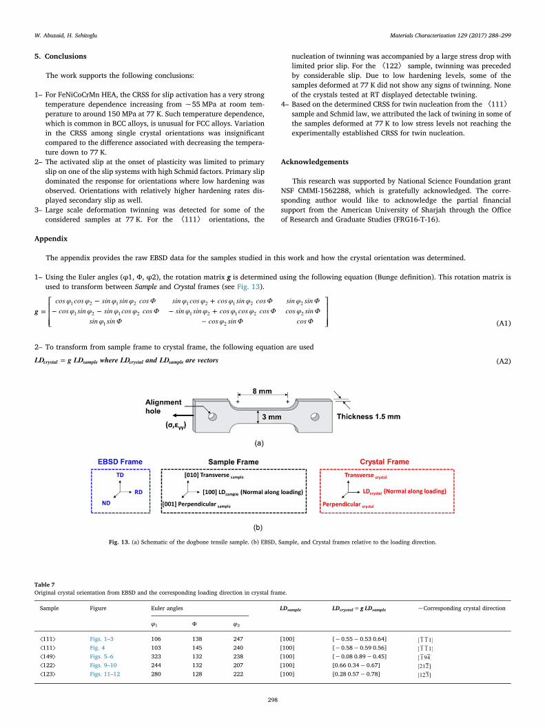
Fig. 13. (a) Schematic of the dogbone tensile sample. (b) EBSD, Sample, and Crystal frames relative to the loading direction.
Table 7Original crystal orientation from EBSD and the corresponding loading direction in crystal frame.
Sample Figure Euler angles LDsample LDcrystal=g LDsample ~Corresponding crystal direction
φ1 Φ φ2
⟨111⟩ Figs. 1–3 106 138 247 [100] [−0.55−0.53 0.64] [ 1− 1−1]⟨111⟩ Fig. 4 103 145 240 [100] [−0.58−0.59 0.56] [ 1− 1−1]⟨149⟩ Figs. 5–6 323 132 238 [100] [−0.08 0.89−0.45] [ 1−94−]⟨122⟩ Figs. 9–10 244 132 207 [100] [0.66 0.34−0.67] [212−]⟨123⟩ Figs. 11–12 280 128 222 [100] [0.28 0.57−0.78] [123−]
W. Abuzaid, H. Sehitoglu Materials Characterization 129 (2017) 288–299
298
3– The sample loading direction was the [100] for all cases. Using the EBSD data, the corresponding direction in crystal frame was calculated usingEqs. (A1) and (A2). The approximate crystal orientations (as used throughout the text) are shown in the last column of Table 7.
References
[1] J.W. Yeh, Recent progress in high-entropy alloys, Ann. Chim. Sci. Mater. (Paris) 31(2006) 633–648.
[2] B. Gludovatz, A. Hohenwarter, D. Catoor, E.H. Chang, E.P. George, R.O. Ritchie, Afracture-resistant high-entropy alloy for cryogenic applications, Science 345 (2014)1153–1158.
[3] D.B. Miracle, O.N. Senkov, A critical review of high entropy alloys and relatedconcepts, Acta Mater 122 (2017) 448–511.
[4] Z.P. Lu, H. Wang, M.W. Chen, I. Baker, J.W. Yeh, C.T. Liu, T.G. Nieh, An assessmenton the future development of high-entropy alloys: summary from a recent work-shop, Intermetallics 66 (2015) 67–76.
[5] F. Otto, A. Dlouhý, C. Somsen, H. Bei, G. Eggeler, E.P. George, The influences oftemperature and microstructure on the tensile properties of a CoCrFeMnNi high-entropy alloy, Acta Mater 61 (2013) 5743–5755.
[6] B. Gludovatz, E.P. George, R.O. Ritchie, Processing, microstructure and mechanicalproperties of the CrMnFeCoNi high-entropy alloy, JOM 67 (2015) 2262–2270.
[7] Z. Zhang, M.M. Mao, J. Wang, B. Gludovatz, Z. Zhang, S.X. Mao, E.P. George, Q. Yu,R.O. Ritchie, Nanoscale origins of the damage tolerance of the high-entropy alloyCrMnFeCoNi, Nat Commun 6 (2015) 10143.
[8] G. Laplanche, A. Kostka, O.M. Horst, G. Eggeler, E.P. George, Microstructureevolution and critical stress for twinning in the CrMnFeCoNi high-entropy alloy,Acta Mater 118 (2016) 152–163.
[9] R. Raghavan, C. Kirchlechner, B.N. Jaya, M. Feuerbacher, G. Dehm, Mechanical sizeeffects in a single crystalline equiatomic FeCrCoMnNi high entropy alloy, Scr Mater129 (2017) 52–55.
[10] C. Zhu, Z.P. Lu, T.G. Nieh, Incipient plasticity and dislocation nucleation ofFeCoCrNiMn high-entropy alloy, Acta Mater 61 (2013) 2993–3001.
[11] F. Otto, N.L. Hanold, E.P. George, Microstructural evolution after thermomecha-nical processing in an equiatomic, single-phase CoCrFeMnNi high-entropy alloywith special focus on twin boundaries, Intermetallics 54 (2014) 39–48.
[12] W. Woo, E.W. Huang, J.-W. Yeh, H. Choo, C. Lee, S.-Y. Tu, In-situ neutrondiffraction studies on high-temperature deformation behavior in a CoCrFeMnNi
high entropy alloy, Intermetallics 62 (2015) 1–6.[13] D. Barbier, N. Gey, S. Allain, N. Bozzolo, M. Humbert, Analysis of the tensile
behavior of a TWIP steel based on the texture and microstructure evolutions, MaterSci Eng A 500 (2009) 196–206.
[14] O. Bouaziz, S. Allain, C.P. Scott, P. Cugy, D. Barbier, High manganese austenitictwinning induced plasticity steels: a review of the microstructure propertiesrelationships, Curr. Opinion Solid State Mater. Sci. 15 (2011) 141–168.
[15] D.R. Steinmetz, T. Jäpel, B. Wietbrock, P. Eisenlohr, I. Gutierrez-Urrutia,A. Saeed–Akbari, T. Hickel, F. Roters, D. Raabe, Revealing the strain-hardeningbehavior of twinning-induced plasticity steels: Theory, simulations, experiments,Acta Mater. 61 (2013) 494–510.
[16] I. Karaman, H. Sehitoglu, K. Gall, Y.I. Chumlyakov, H.J. Maier, Deformation ofsingle crystal Hadfield steel by twinning and slip, Acta Mater 48 (2000) 1345–1359.
[17] L. Patriarca, A. Ojha, H. Sehitoglu, Y.I. Chumlyakov, Slip nucleation in single crystalFeNiCoCrMn high entropy alloy, Scr Mater 112 (2016) 54–57.
[18] L. Patriarca, W. Abuzaid, H. Sehitoglu, H.J. Maier, Y. Chumlyakov, Twin nucleationand migration in FeCr single crystals, Mater Charact 75 (2013) 165–175.
[19] W. Abuzaid, H. Sehitoglu, J. Lambros, Plastic strain localization and fatigue micro-crack formation in Hastelloy X, Mater Sci Eng A 561 (2013) 507–519.
[20] J. Carroll, W. Abuzaid, J. Lambros, H. Sehitoglu, An experimental methodology torelate local strain to microstructural texture, Rev. Sci. Instrum. 81 (2010) 083703.
[21] Z. Wu, H. Bei, G.M. Pharr, E.P. George, Temperature dependence of the mechanicalproperties of equiatomic solid solution alloys with face-centered cubic crystalstructures, Acta Mater 81 (2014) 428–441.
[22] M.A. Meyers, O. Vöhringer, V.A. Lubarda, The onset of twinning in metals: aconstitutive description, Acta Mater 49 (2001) 4025–4039.
[23] I. Kireeva, Y. Chumlyakov, Z. Pobedennaya, D. Kuksgauzen, I. Karaman,H. Sehitoglu, Mechanisms of plastic deformation in [1¯11]-oriented single crystalsof FeNiMnCrCo high entropy alloy, AIP Conf. Proc. 1783 (2016) 020090.
[24] S. Huang, W. Li, S. Lu, F. Tian, J. Shen, E. Holmström, L. Vitos, Temperaturedependent stacking fault energy of FeCrCoNiMn high entropy alloy, Scr Mater 108(2015) 44–47.
W. Abuzaid, H. Sehitoglu Materials Characterization 129 (2017) 288–299
299