creating places - planning service · creating places achieving quality in residential developments...
TRANSCRIPT

Creating Places
achieving quality in residential
developments
incorporating guidance on layout and access
Creating Places
achieving quality in residential
developments
incorporating guidance on layout and access
May 2000
The housing we build today will not only help to shape our environment in the immediate future, it will also be a legacy determining the environmental quality of many areas throughout the 21st century.
This guide describes the contributions to quality and sustainability that developers in Northern Ireland will be expected to make through the design of new residential developments. It seeks to ensure that what is designed and built today will be cherished by both present and future generations.
i

ii

The art of urban design has become better understood over the past few years. We now appreciate how good design can make a difference in shaping our built environment, and we know how the sustainability of development and our quality of life can be enhanced by more careful thought about the places we create.
The Quality Initiative launched a few years ago was a call for action - a call for developers and public officials to do better. The Government wants to build on this approach, and has prepared this guidance as a sound basis for lifting the quality of all new residential developments throughout Northern Ireland.
The design of a housing development, incorporating roads that are the responsibility of the road authority, has to be carefully regulated to a consistently applied safety standard. But the key to the creation of quality places is in the hand of the designer, not the regulator.
If we are to achieve quality in the places we create, the designers and those who regulate must work together. Both must acknowledge that the process requires early agreement on an overall design concept that is appropriate to the site.
This guidance demonstrates how quality places, whether created in rural surroundings or an urban setting, will respect their context and make the most of existing site characteristics. A well-designed layout protects and respects natural habitat and heritage, encourages walking and cycling and provides convenient access to public transport. Traffic is calmed and tree-lined avenues and open spaces are provided. The places created are distinctive, attractive and safe, and serve well the needs of residents of all ages, as well as those of visitors and service providers.
Developers will want to employ imaginative and skilful designers and give them enough time to do it right. In the spirit of this guidance planners and road engineers will, for their part, want to respond positively to housing layout proposals that are worked up comprehensively - and that are demonstrably well designed.
All new developments provide opportunities to create surroundings that future generations will cherish - the conservation areas of tomorrow.
Foreword
H.S. McKay Chief Executive, Planning Service Department of the Environment
C. James Chief Executive, Roads Service Department for Regional Development
iii

iv

Contents
page
Preamble ix
Introduction 1Quality and sustainability through design 2Scope and status of the guide 3Design skills 4Consultations 4Flexibility in application 5The structure of the guide - an integrated approach 6
Part 1: Context for overall design character 7
1 Respecting the local setting 8Main objectives 8Design context and visual character 9The local landscape and townscape 10Land uses 12Movement patterns 14Parking patterns 15Utilities 15
2 Responding to the site 16Main objectives 16History of the site 17Landform 20Flora and fauna 23Climate 24Noise and other nuisances 24
3 Creating attractive surroundings and places to live 26Main objectives 26An overall design concept 27Contexts for design concepts 30Creating spaces 32Landmark features 36Variety and distinctiveness 37The totality 38
Part 2: Main elements of design 41
4 Landscape design 42Main objectives 42Quality in landscape design 43Existing landscape features 43Soft landscape works 44Hard landscape works 46Landscape management and maintenance 47
v

page
5 Open space 48Main objectives 48Public open space 49Routes for movement 51Private open space 51
6 Local neighbourhood facilities 56Main objectives 56Types of facilities 57Location 57
7 Dwellings 60Main objectives 60Dwelling mix 61Building density and form 62Layout arrangements 62Dwelling planning 66
8 Pedestrian and cycle routes 68Main objectives 68Foootways 69Cycle tracks 70Verges 70Footpaths 71General considerations 72Detailed design 73
9 Bus routes 74Main objectives 74Consultations 75Bus route layout 75Carriageways 76Bus stops 77
10 Routes for cars and service vehicles 78Main objectives 78Creating permeable layouts 79Deterring non-access vehicular traffic 80Restraining vehicle speeds 81Types of restraints 83Spacing of restraints 86Direct access to dwellings 87Access to community buildings 90
11 Parking provision 92Main objectives 92Visual character 93Numbers of spaces required 93Security and convenience 94Layout arrangements 95
vi

page
12 Provision for services 98Main objectives 98Location of services underground 99Lighting 102Emergency services 102Refuse collection 103Post boxes 103Telephone call boxes 103Aerials and satellite dishes 103Street nameplates and dwelling numbering 103
Part 3: Detailed design requirements 104
13 Planting 105Specialist advice 106Retaining existing vegetation 106New planting 107Minimising maintenance 108Design to minimise damage to trees 108Potential hazards 108Showing trees on drawings 109Acceptable species of trees and shrubs 109
14 Footways, verges, footpaths and cycle tracks 112Footways 112Verges 113Footpaths 113Cycle tracks 114
15 Special facilities for buses 116Lay-bys 116Turning space 116Bus termini 117
16 Carriageways 118Main requirements 118Turning spaces 122Junction design 123Carriageway surfacing 126Carriageway edging 127
17 Visibility 128Main requirements 128Visibility at junctions 129Visibility on bends 130Visibility above the ground 131
18 Speed restraints 132Changes in horizontal alignment 132Vertical displacement measures 135Complementary measures 138
vii

page
19 Shared surfaces 140Visual character 140Entrances 140Configuration 141Visibility 142Services underground 142Surfacing and edge restraints 142
: numbers and dimensions 14420 Parking spacesUnderlying principles 144Numbers of spaces required 144Bicycle parking spaces 148In-curtilage carports and garages 148In-curtilage driveways and hardstandings 149Parking bays contiguous with carriageways 149Grouped parking areas 150Demarcation of communal parking spaces 151
21 Utilities’ services 152Electricity 152Gas 153Water 153Sewers 153Telecommunications 153Lighting 154
Appendices 157Appendix A: Definitions 158Appendix B: Information required 161Appendix C: Adoption and maintenance 163Appendix D: Planning and Roads Service Offices 165Appendix E: Public consultation 167Appendix F: Regional planning policy publications 168
Selected further reading 169
Acknowledgments 171
viii
PreambleThis guide has been produced jointly by the Planning Service, an Agency within the Department of the Environment, and the Roads Service, an Agency within the Department for Regional Development. It is intended to help developers achieve high quality and greater sustainability in the design of all new residential developments in Northern Ireland.
The guide was researched and prepared on behalf of both Departments by Professor Mike Jenks (Oxford Brookes University) and John Noble (consultant) with the assistance of Laurence Pattacini. The contributions of Mike Stanley, Graham Smith, Paul Murrain and Ian Davison are also acknowledged.
The guide is for use by all those involved in the design of new residential developments and the rejuvenation of existing housing areas – primarily house-builders, architects, landscape architects, urban designers, planners and road engineers. It is intentionally not slanted towards any one profession or group, in the belief that what is said here is relevant to all those who have an interest in the design of the places where we live.
The advice contained in the guide has been informed by publications from Great Britain, the Republic of Ireland and other parts of Europe, in particular the guidance presented in:
• Design Bulletin 32, Residential Roads and Footpaths – Layout Considerations (2nd edition), Department of the Environment / Department of Transport (1992), and
• Places Streets and Movement, A Companion Guide to Design Bulletin 32, Department of the Environment, Transport and the Regions (1998).
The process of producing the guide was undertaken jointly by a range of professional disciplines within a number of Government Departments. It involved public consultation and discussions with housing developers, design professionals, service providers, public transport undertakers and other interested parties. The aim for the guide has been to strike a balance between competing interests.
Thanks are due to all those organisations and individuals who provided comments on the public consultation draft of the guide entitled ‘New Residential Developments: Overall Design Character and Requirements for Access and Parking’, commonly referred to as the “Blue Book” (see Appendix E).
ix

The guide constitutes supplementary planning guidance and references in text to the ‘Department’ refer to the Department of the Environment which is responsible for planning control in Northern Ireland.
With the publication of this guide the following document is withdrawn:
• Layout of Housing Roads - Design Guide, DOE (1988).
Requirements for the construction and specification of roads are not covered in the guide. These are set out in the Private Streets (Construction) Regulations (Northern Ireland) 1994.
Nothing in the guide should be read as a commitment that public resources will be provided for any specific project. All proposals for expenditure by Government are subject to economic appraisal and will also have to be considered having regard to the overall availability of resources.
All diagrams within the guide are for illustration purposes only and should not be scaled.
Page x
1
Creating Places
Introduction
Introduction
Quality and sustainability through design
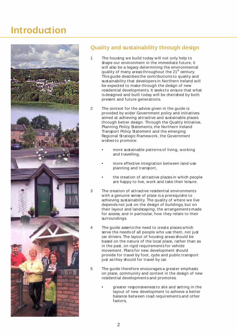
1 The housing we build today will not only help to shape our environment in the immediate future, it will also be a legacy determining the environmental quality of many areas throughout the 21st century. This guide describes the contributions to quality and sustainability that developers in Northern Ireland will be expected to make through the design of new residential developments. It seeks to ensure that what is designed and built today will be cherished by both present and future generations.
2 The context for the advice given in the guide is provided by wider Government policy and initiatives aimed at achieving attractive and sustainable places through better design. Through the Quality Initiative, Planning Policy Statements, the Northern Ireland Transport Policy Statement and the emerging Regional Strategic Framework, the Government wishes to promote:
• more sustainable patterns of living, working and travelling,
• more effective integration between land-use planning and transport,
• the creation of attractive places in which people are happy to live, work and take their leisure.
3 The creation of attractive residential environments with a genuine sense of place is a prerequisite to achieving sustainability. The quality of where we live depends not just on the design of buildings, but on their layout and landscaping, the arrangements made for access, and in particular, how they relate to their surroundings.
4 The guide asserts the need to create places which serve the needs of all people who use them, not just car drivers. The layout of housing areas should be based on the nature of the local place, rather than as in the past, on rigid requirements for vehicle movement. Plans for new development should provide for travel by foot, cycle and public transport just as they should for travel by car.
5 The guide therefore encourages a greater emphasis on place, community and context in the design of new residential developments and promotes:
• greater responsiveness to site and setting in the layout of new development to achieve a better balance between road requirements and other factors,
2
Introduction• developments designed to emphasise a sense of
place and community, with movement networks to enhance those qualities,
• the reduction of car use through the provision of local neighbourhood facilities and public transport within walking distance of housing,
• the detailed design of roads, footpaths and cycle routes to avoid dominance by the car,
• a move away from overly prescriptive standards to a more integrated approach to achieving high quality and sustainable designs.
6 This will require good design that balances all the factors influencing quality and sustainability and which responds to a local context by making the best of a site and its surroundings.
Scope and status of the guide
7 This guide is intended for use in the design of all proposals for residential development throughout Northern Ireland, from small-scale infill housing schemes to major projects on large sites incorporating a mix of uses. It therefore contains more information than is needed for any one site - nevertheless, the principles and standards in the guide will be used by the Department as a basis for assessing any proposal. Accordingly, the guide should be read and understood as a whole.
8 The guide constitutes supplementary planning guidance. It does not take precedence over the provisions of local development plans or regional policy publications such as Planning Policy Statements (see appendix F), but should be read in conjunction with the relevant contents of these publications and any applicable non-statutory local design guides, development briefs or master-plans. Such documents may be especially relevant in respects such as:
• the design character of the development,
• the protection of existing trees and other important natural or topographical features,
• the protection of archaeological remains and historic sites or buildings,
• access routes for pedestrians, cyclists, public transport and other vehicles,
• requirements for open space provision,
• requirements for the provision of local neighbourhood facilities,
3

• building density, or the mixture of dwelling types and tenures to be provided,
• the amount of provision to be made for parking.
9 When in doubt about which aspects of planning policies and which parts of this guide will be most applicable to their project, developers should consult the Department’s Divisional Planning Offices (see Appendix D).
Design skills
10 To achieve the quality of design expected, developers will need to employ experienced design teams which may include architects, landscape architects and highway engineers and, for larger developments, planners or urban designers. Conservation specialists will be needed where protected flora and fauna, archaeological sites and monuments, listed buildings or conservation areas are involved, and arboriculturists where existing trees and major shrubs need to be retained and maintenance plans for planted areas have to be prepared.
11 Developers should give their design teams enough time to appraise the site and its setting and identify the visual and other characteristics of the context needed for design. This guide gives examples of the information and analyses needed to provide a basis for design. Adequate time will also be needed to create an appropriate design concept and produce enough information for the Department to assess the proposal.
12 Appendix B sets out requirements for information to be submitted with planning applications. This information is greater than in the past but does not exceed that which any developer who pursues quality in design will normally need to produce. These and other design costs will need to be taken into account in the price paid for the development land.
Consultations
13 It is in the interests of developers to undertake consultation with a range of agencies prior to drawing up detailed schemes.
14 The Department should be consulted about its overall planning requirements, such as policies for the protection of site features or the provision of open space. Advice regarding the adoption and maintenance of roads, footpaths, cycle tracks and parking areas should be sought from the Roads Service (see also Appendix C).
4

Introduction
15 Developers should also consider consulting a range of bodies with statutory and other duties, including:
• public utilities and telecommunications operators,
• bus operators,
• education authorities,
• the emergency services.
16 When the development is large, or in an especially sensitive location, developers may also wish to consult with local district councils, representatives of local organisations and community groups and others with an interest in the development. Presentations and discussions at this early stage will highlight local issues of concern, and help to ensure that design proposals are better understood by local people and public representatives.
Flexibility in application
17 To achieve the high quality of design that the Department expects, it will not always be practicable for developers to give equal weight to each aspect of the guidance given here - a balance will have to be struck between competing objectives. It is in this sense that the Department will be flexible when assessing proposals against the requirements set out in this guide. For example, a more flexible approach to layout requirements may be appropriate where it is necessary to protect important heritage or landscape features.
18 Prescriptive requirements in the guide have been kept to a minimum to give developers as much scope as possible to produce high quality designs. Scope for flexibility is implicit in those requirements cited as being ‘around’ a specified numerical value.
19 The Department will consider requests from developers to relax these and other more precisely specified requirements when this would provide clear benefits in terms of quality. When making such requests developers must demonstrate that the proposal will meet the design principles underlying the requirement and that the design quality being proposed could not be achieved without such flexibility.
20 Developers, when considering the requirements for road design, should be aware that the Department has given a high priority to the aim of creating safe surroundings. This priority will apply equally when requests for relaxation are being considered.
5

21 The Department will consider each development on its individual merits and developers should not therefore assume that a relaxation given for one development will be applied to another.
The structure of the guide - an integrated approach
22 This guide is structured around the process of design so that all the elements of layout and design are considered as a whole. It is intended to encourage the interconnection of design considerations of the setting, landscape design, circulation patterns and buildings to form a coherent design structure. The guide is in three parts:
• Part 1 – considers the wider context of the local setting, the characteristics of the site for development, and strategies for the overall design character of a proposal.
• Part 2 – gives guidance on the main elements needed to achieve high quality design, from the overall landscape and urban design considerations to the layout of dwellings, means of access and patterns of movement.
• Part 3 – provides detailed design information and standards.
6

Creating Places
Part 1
Context for overall design
character

1 Respecting the local setting
To be attractive and function well, the design should take into account the characteristics of the local setting. This section describes aspects relevant to the setting that will need to be analysed as a basis for design, and includes guidance on assessments of design context, landscape and townscape form, land uses and movement patterns.
Main objectives
1.01 The design should pay particular attention to the characteristics of the local setting. The context of the site should be analysed to ensure that the development will:
• respect the qualities of the best of the surrounding landscapes and townscapes,
• provide spatial characteristics and building forms that are sympathetic to the surroundings,
• respond to existing land uses and provide an appropriate mix of dwellings and uses,
• integrate with existing patterns of movement.
8
1: Respecting the local setting
Design context and visual character
The Northern Ireland context
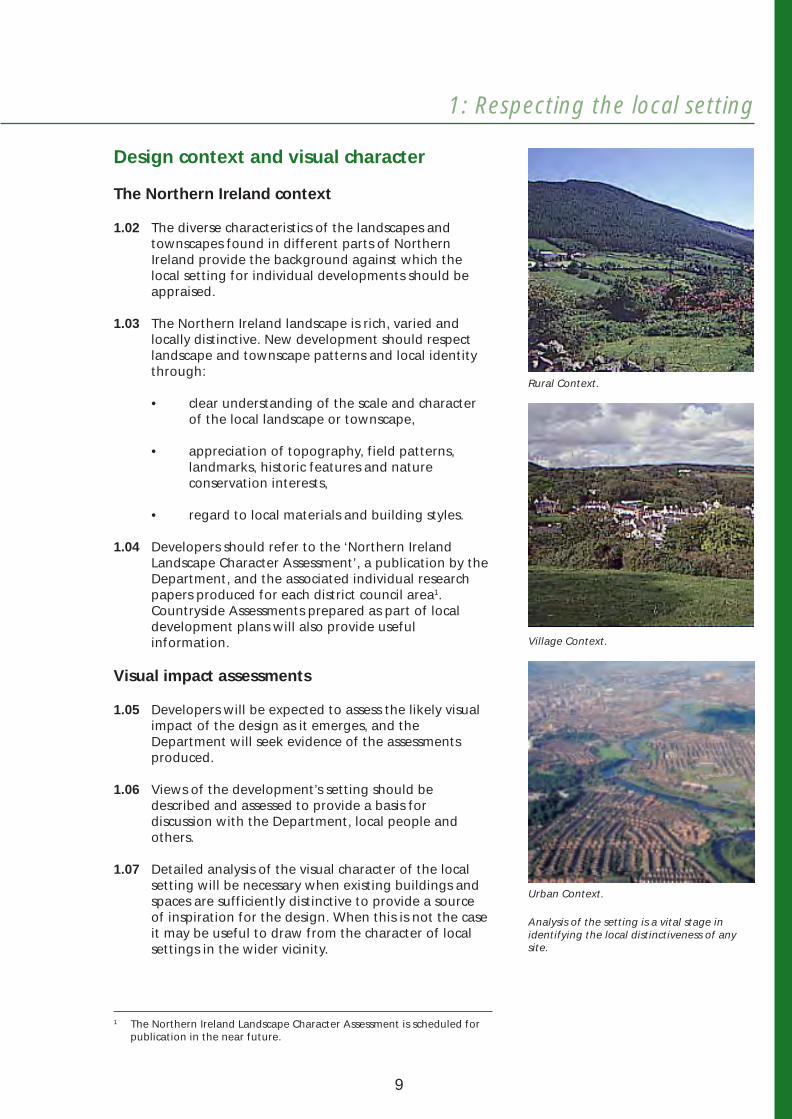
1.02 The diverse characteristics of the landscapes and townscapes found in different parts of Northern Ireland provide the background against which the local setting for individual developments should be appraised.
1.03 The Northern Ireland landscape is rich, varied and locally distinctive. New development should respect landscape and townscape patterns and local identity through:
• clear understanding of the scale and character of the local landscape or townscape,
• appreciation of topography, field patterns, landmarks, historic features and nature conservation interests,
• regard to local materials and building styles.
1.04 Developers should refer to the ‘Northern Ireland Landscape Character Assessment’, a publication by the Department, and the associated individual research papers produced for each district council area1. Countryside Assessments prepared as part of local development plans will also provide useful information.
Visual impact assessments
1.05 Developers will be expected to assess the likely visual impact of the design as it emerges, and the Department will seek evidence of the assessments produced.
1.06 Views of the development’s setting should be described and assessed to provide a basis for discussion with the Department, local people and others.
1.07 Detailed analysis of the visual character of the local setting will be necessary when existing buildings and spaces are sufficiently distinctive to provide a source of inspiration for the design. When this is not the case it may be useful to draw from the character of local settings in the wider vicinity.
Rural Context.
Village Context.
Urban Context.
Analysis of the setting is a vital stage in identifying the local distinctiveness of any site.
The Northern Ireland Landscape Character Assessment is scheduled for publication in the near future.
9
1
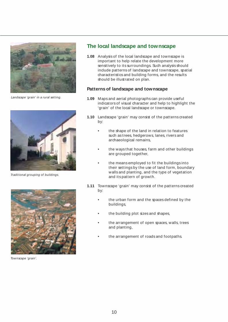
Landscape ‘grain’ in a rural setting.
Traditional grouping of buildings.
Townscape ‘grain’.
The local landscape and townscape
1.08 Analysis of the local landscape and townscape is important to help relate the development more sensitively to its surroundings. Such analysis should include patterns of landscape and townscape, spatial characteristics and building forms, and the results should be illustrated on plan.
Patterns of landscape and townscape
1.09 Maps and aerial photographs can provide useful indicators of visual character and help to highlight the ‘grain’ of the local landscape or townscape.
1.10 Landscape ‘grain’ may consist of the patterns created by:
• the shape of the land in relation to features such as trees, hedgerows, lanes, rivers and archaeological remains,
• the ways that houses, farm and other buildings are grouped together,
• the means employed to fit the buildings into their settings by the use of land form, boundary walls and planting, and the type of vegetation and its pattern of growth.
1.11 Townscape ‘grain’ may consist of the patterns created by:
• the urban form and the spaces defined by the buildings,
• the building plot sizes and shapes,
• the arrangement of open spaces, walls, trees and planting,
• the arrangement of roads and footpaths.
10

1: Respecting the local setting
Spatial characteristics
1.12 The visual characteristics of the three-dimensional spaces created by buildings, walls, trees and hedges should be analysed. This may include: how spaces relate to each other; the way planting affects the spaces; the grouping of buildings and the visual character of the overall scene, whether formal or informal.
Building forms and elements related to buildings
1.13 The analysis should include the visual characteristics of building forms and related elements, such as: aspect and orientation; proportion; the balance of solid to void; the shapes and details of roofs, chimneys, windows and doors and the materials used. Details of walls, gates, street furniture, planting and paving should also be noted.
Cues for design can be drawn from a careful analysis of the best traditions and details in local design.
Interesting building forms, materials and street furniture in an attractive townscape setting.
11

Land uses
1.14 The land uses surrounding the site should be analysed and the results illustrated on plan. This will normally include the following aspects.
Open spaces
1.15 Plans will need to show the locations and uses of open spaces both on and in the vicinity of the site together with any that will result from previously approved planning applications. Open spaces likely to be used by residents living in the development should be noted as these will affect the demand for, and location of, on-site provision for formal and informal open spaces.
Local neighbourhood facilities
1.16 The locations and uses of existing local facilities and community buildings (schools, health centres, shops etc.) both on and in the vicinity of the site - together with any anticipated developments that will result from previously approved planning applications should be shown. Buildings and facilities likely to be used by residents living in the development should be noted as these may affect the demand for, the location of, and access to any additional provision required.
Dwellings
1.17 Plans should show the locations and types of existing dwellings both on and in the vicinity of the site together with any anticipated developments that will result from previously approved planning applications. This may affect the dwelling mix required in the development.
12

1: Respecting the local setting
offices & small industry
secondary school
sports facilities
sports facilities
secondary school
primary school
primary school
church
church
the site
woodland
countryside
countryside
local shops
pub
settlement limit settlement limit
settl
emen
t lim
it
Schematic land use analysis of a greenfield site at the edge of an existing town.
views existing trees
existing historical buildings
existing connections
to site
Local Distributor
Distributor with Bus Route
Access Road Lighter traffic
Pedestrian Movement
Cycle Route
Access Road
Access Road Heavy traffic
SITE
Industry
ExistingCar Park
Church
Park
Community Centre
Shops
Industry
Industry
Schematic analysis of an inner urban site, highlighting existing routes, views and places of interest.
For new developments scaled maps and plans will be required for the analyses of the site and its surroundings.
13

Movement patterns
1.18 Existing routes for the movement of pedestrians, bicycles and vehicles surrounding the site and any features that may influence the provision and layout of footpaths, cycle tracks and roads in the development should be identified and shown on plan. The Department and the Roads Service should be consulted to find out whether a Transport Assessment should be undertaken.
Pedestrians and cyclists
1.19 The existing pedestrian and cycle route network should be identified on plan. The location of proposed cycle routes or other special provision for cyclists will also need to be recorded - to help ensure that adequate connections are provided such as cycle track links between the development, local attractions and schools.
1.20 The plan should indicate existing and potential points of access to the site for pedestrians and cyclists (including any links that ought to be provided to adjacent developments or future sites). It should also indicate which of these access points would be used to reach destinations such as off-site public open spaces, community buildings and bus stops.
1.21 Any existing rights of way for pedestrians and cyclists should be identified and integrated into the development - making sure they will not be in out of the way places open to abuse in the form of illegal dumping or other anti-social activities.
Buses
1.22 Existing bus routes and the location of bus stops should be indicated on plan. The plan should also highlight existing and potential points of access for buses to the site (including any links that ought to be provided to adjacent developments or future sites) and which of these access points would be used by buses that need to cross the site.
It is important to identify existing routes for movement so that the development can provide appropriate linkages.
14

1: Respecting the local setting
Cars and service vehicles
1.23 The existing road network should be identified on plan, together with any future road proposals in the vicinity of the site. The plan will also need to indicate existing and potential points of vehicular access to the site (including any links that ought to be provided to adjacent developments or future sites) and which of these access points would be used by:
• non-access vehicular traffic taking short cuts across the site,
• residents going to and from the site for activities associated with work or leisure,
• vehicles servicing the site.
1.24 Any existing rights of way for vehicles should be identified and integrated into the development.
1.25 Existing or proposed speed limits along roads serving the site should be noted as these may need to be taken into account when setting target maximum speeds for roads within the site.
Parking patterns
1.26 Patterns of on-street parking on the perimeter roads and elsewhere nearby will need to be recorded, together with existing or proposed parking controls and waiting restrictions. These could affect requirements for on-site parking provision.
Utilities
1.27 A plan will be needed to show the locations of existing statutory and other utility services. These will normally follow the routes provided by the existing roads, but there may be major service routes in other locations that would influence the overall form of the layout.
15
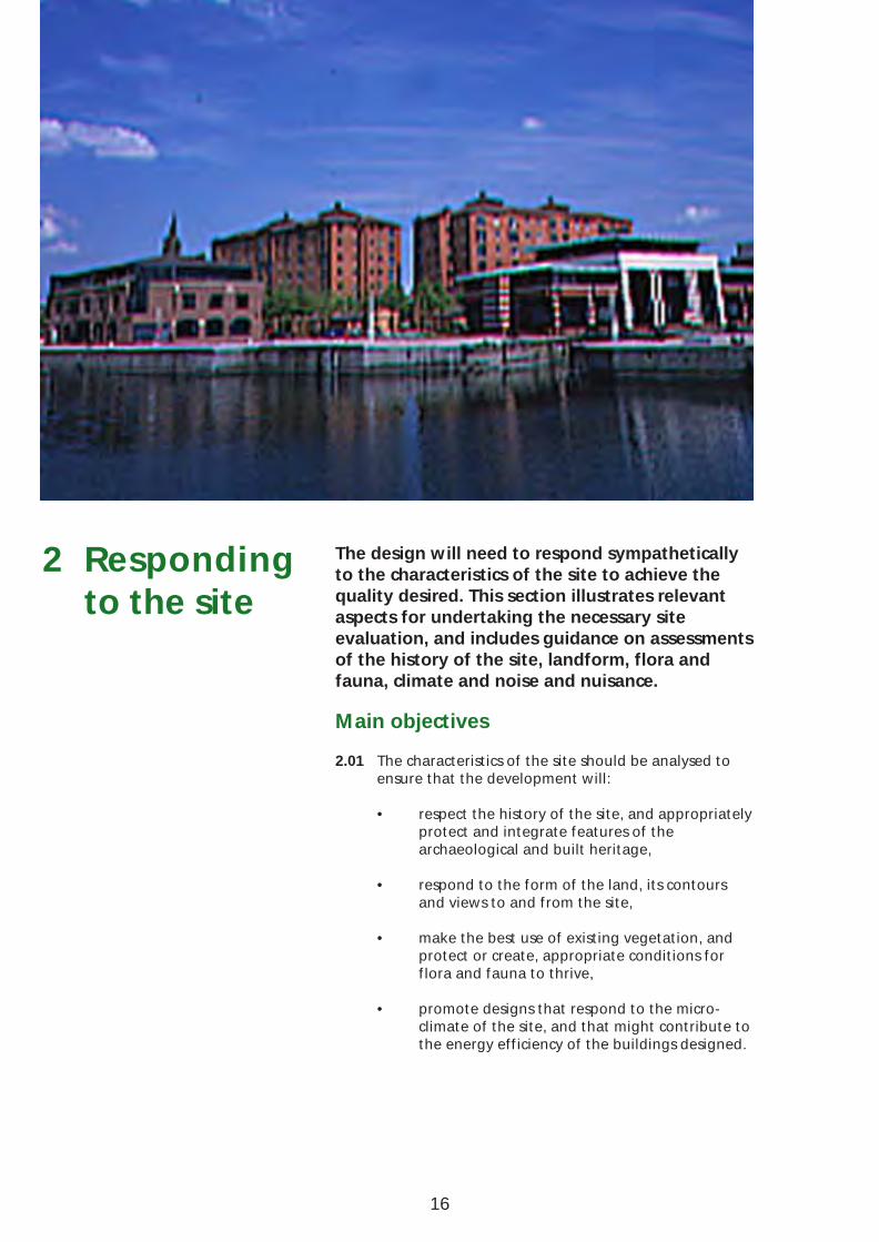
2 Respondingto the site
The design will need to respond sympathetically to the characteristics of the site to achieve the quality desired. This section illustrates relevant aspects for undertaking the necessary site evaluation, and includes guidance on assessments of the history of the site, landform, flora and fauna, climate and noise and nuisance.
Main objectives
2.01 The characteristics of the site should be analysed to ensure that the development will:
• respect the history of the site, and appropriately protect and integrate features of the archaeological and built heritage,
• respond to the form of the land, its contours and views to and from the site,
• make the best use of existing vegetation, and protect or create, appropriate conditions for flora and fauna to thrive,
• promote designs that respond to the microclimate of the site, and that might contribute to the energy efficiency of the buildings designed.
16

2: Responding to the site
History of the site
Local sources
2.02 Each site has a unique history that may be drawn upon to help give the design a distinctive local character. Design references may be gleaned from sources such as the Northern Ireland Monuments and Buildings Record, the Public Record Office of Northern Ireland and local libraries. These can help provide material such as old maps, townland names, photographs and illustrations and other records, such as histories of local events, customs and people.
2.03 The material gathered should be presented in ways that identify any physical features of historic relevance that should be retained, protected and integrated into the development. There may also be routes, buildings or other features that no longer exist but which, if reinstated, would enhance the landscape or townscape or add value to the development by highlighting its past. The visual and written material gathered may also be a useful source of names for the development and for individual buildings, streets and other spaces.
Local sources of historic information should be used to ensure that the development will respect the history of the site, and inform the overall design concept.
(PRONI ref: OS8/34/1/2)
17

Archaeological sites and monuments
2.04 The presence of archaeological remains within or adjacent to a site will influence the design and layout and can contribute to the overall character of the development. Archaeological remains may be visible, as a monument, or survive only below ground. Developers will need to identify such remains and integrate these appropriately into the development.
2.05 A monument should form an integral part of the design and layout of the development. It can be a landmark or a minor focal point and may be used as a location for informal recreation, or form part of a larger open space. It should not be fenced-off to prevent access, or left as unmanaged backlands, as ‘land-locking’ can lead to neglect and attract dumping and vandalism. Building should respect the immediate surroundings of the monument and face onto the space created to provide casual supervision. In some circumstances, it may be appropriate to integrate a monument into private garden space – through single ownership for a small feature, such as a standing stone, or shared ownership for a larger feature.
2.06 The use of a monument as a roundabout or traffic island should generally be avoided, since this prevents access and tends to isolate rather than integrate the monument into the development. However, using a monument to introduce a curving road-line or assist in traffic calming can add interest to the development. Pedestrian and cycle routes should also respect monuments.
2.07 Proposals for the presentation and landscaping of a monument should be addressed, and must be archaeologically sensitive and based on professional advice. Masonry monuments, in particular, are likely to require specialist assessment and treatment. Earthwork monuments, with rough or eroded surfaces, may need to be conserved by adding appropriate materials, but never by levelling the existing uneven surface. Tree planting should normally be kept away from monuments, because roots can penetrate and damage buried remains. All works to monuments should be completed before residents move in, so that they appear as managed spaces.
Monuments can create attractive and 2.08 Existing field drainage around monuments will be interesting breaks in developments. They altered by development. New drainage measuresshould be integrated appropriately into the should therefore be provided by developers todesign and layout as major or minor focal points with sufficient space around them - prevent local problems with run-off from the monuments are never enhanced by houses or monument, maintain its ground conditions and ensure roads being built too close to them. the continuing survival of the archaeological remains.
18

2: Responding to the site
2.09 Where buried archaeological remains exist within a site, these may be protected by adding protective overburden and thus sealing them for long-term preservation. It may be possible to use the space created in this way provided it is certain that any such use will not damage the remains, for example, through compression or other changes to the buried environment. Such areas may be suitable for use as open space or private gardens, or alternatively sealed beneath a hard surface, such as a road, pathway or car-parking. In some cases it may be possible to design a building to secure the preservation of buried remains.
2.10 There may also be occasions where development will be permitted which will damage or destroy archaeological remains of lesser importance. This will be conditional on the completion, by the developer, of licenced excavation and recording of the remains before the development commences.
Listed buildings
2.11 Certain housing sites may contain listed buildings. These should be identified and retained as part of the development. Care must be taken to ensure that they are integrated appropriately into the layout of the scheme and that their immediate setting is respected. The distinctive design of such buildings may be used to inform the appearance and character of buildings in their vicinity and they can act as a focal point or landmark feature within the development.
Redevelopment sites
2.12 On redevelopment sites, existing buildings, walls, paving or other features of sufficient visual quality to be retained, should be identified. On former industrial or other brown-field sites, interesting features, such as machinery that could be retained, should be noted. The condition of buildings and other features will need to be assessed and any necessary remedial works described.
2.13 Redevelopment sites may have land shapes that were created to allow for industrial and other processes. These features, if retained, can give individuality to a design and a sense of continuity with the past.
2.14 Historic street patterns should also be noted and retained wherever possible.
Licenced excavation of archaeological remains may be necessary before development commences.
A listed building well integrated with new housing.
Mixed-use development respecting the industrial heritage.
19

Landform
Contours
2.15 The contours of the land should be indicated on plans and relevant sections produced. The shape and composition of the land should be respected by the development and, where practicable, retained.
Analysis of contours.
2.16 Flat sites require the least disturbance to the land, are economic to build on and conducive to walking and cycling. Designers will have more options than on sloping sites to create different kinds of layout forms although ways other than the shape of the land will have to be found to create a sense of distinctiveness. Existing buildings, street layouts and patterns of trees and hedgerows will help in this respect and should be recognised in the design concept.
20
2: Responding to the site
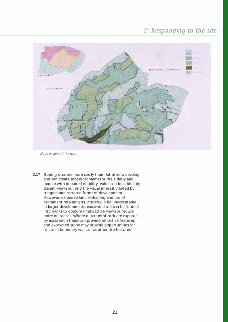
Slope analysis of the site.
2.17 Sloping sites are more costly than flat sites to develop and can create access problems for the elderly and people with impaired mobility. Value can be added by distant views out and the visual interest created by stepped and terraced forms of development. However, extensive land reshaping and use of prominent retaining structures will be unacceptable. In larger developments, excavated soil can be formed into banks to obscure unattractive views or reduce noise nuisances. Where outcrops of rock are exposed by excavation these can provide attractive features, and excavated stone may provide opportunities for re-use in boundary walls or as other site features.
21

Analysis of views into and from the site.
Views
2.18 An analysis of views into and from the site should be undertaken to identify distant features, attractive views and those that are unsightly. Views will be affected by site contours, existing buildings and landscape features. These should be noted in order to influence layout strategies and provide vistas that will maximise attractive and important views, and also to mask the unsightly.
Ground conditions
2.19 The composition of the ground, including the geology and soil types, may affect the location of buildings or planting to be used and, where appropriate, should be analysed. For instance, buildings will generally need to be located well away from trees on clay soils a significant layout constraint. Landfill and contamination is also likely to be especially relevant to the redevelopment of many older industrial sites.
22

2: Responding to the site
2.20 Streams, rivers and ponds within or bounding sites should be identified. Sympathetic planting and other works may be needed to make these safe and attractive features. Any susceptibility to flooding will need to be identified and taken into account in the design and layout. Bridges, culverts and balancing ponds may also need to be constructed. The water table level may be an important consideration, and the absorption of surface water into the ground may need to be arranged specifically to help maintain the water table level and keep balancing ponds topped up.
Flora and fauna
Existing vegetation
2.21 The appropriate retention of existing vegetation and its enhancement with new planting will help to integrate development into its setting. This can give an impression of maturity from the outset and will be a major determinant of the layout.
2.22 All existing vegetation and other landscape features should be surveyed and recorded. Existing trees, hedgerows and shrubs likely to continue to grow for long periods of time should be candidates for retention and protection. The condition of existing vegetation will also help provide useful information for new planting. New buildings and roads will need to be located to allow for the survival of vegetation to be retained and to minimise amenity problems. In addition paving will need to be porous over a large enough area to provide trees with sufficient rainwater - a space-consuming requirement that may stronglyinfluence the layout (see also Section 4).
Wildlife
2.23 Designated sites of nature conservation importance and existing wildlife corridors likely to be affected by the development should be identified with a view to their preservation or re-creation.
2.24 The presence of species protected under the provisions of the Wildlife (Northern Ireland) Order 1985 should also be identified and the likely effects of the development assessed. Developers may be required to take special measures to protect such species and their activities. For example, the presence of badgers’ setts may require areas to be left undisturbed.
Flora and fauna should be protected.
An existing pond integrated with the landscaping of a new housing scheme.
23
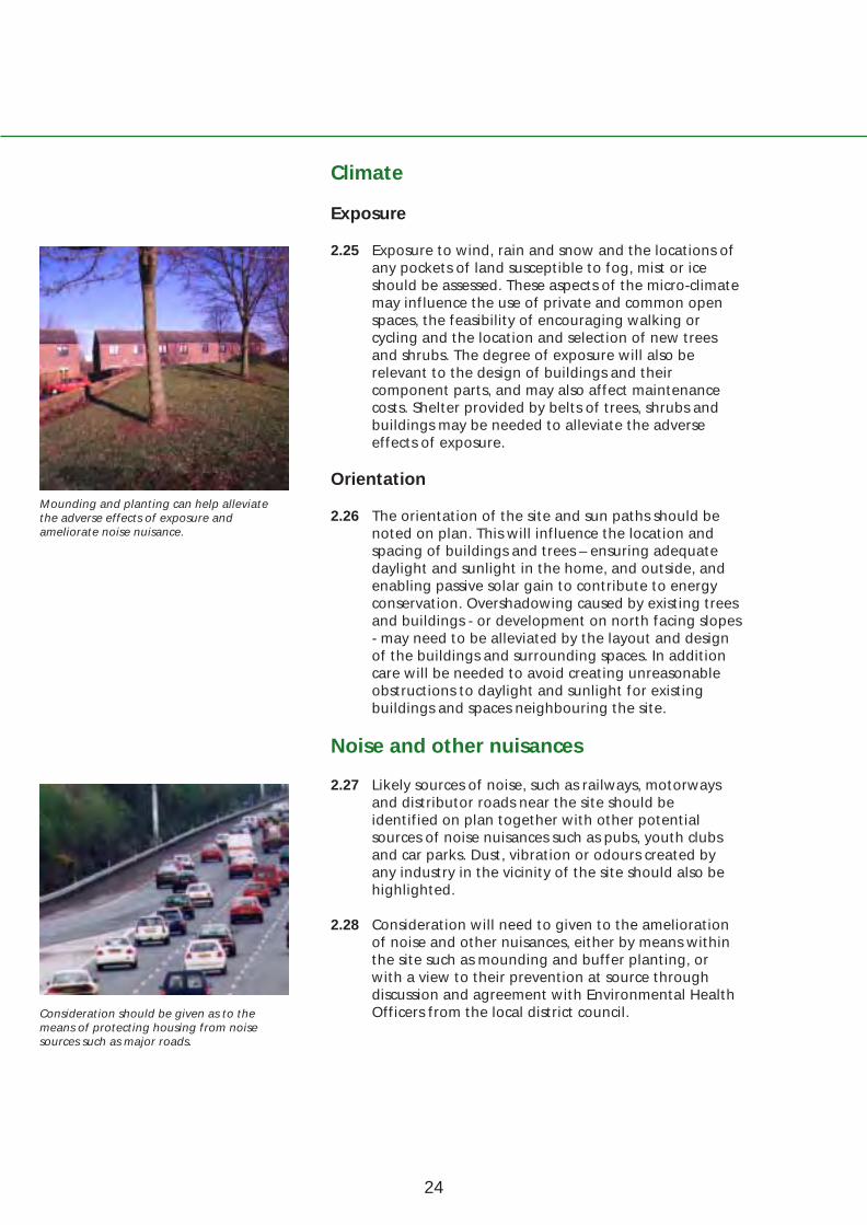
Mounding and planting can help alleviate the adverse effects of exposure and ameliorate noise nuisance.
Consideration should be given as to the means of protecting housing from noise sources such as major roads.
Climate
Exposure
2.25 Exposure to wind, rain and snow and the locations of any pockets of land susceptible to fog, mist or ice should be assessed. These aspects of the micro-climate may influence the use of private and common open spaces, the feasibility of encouraging walking or cycling and the location and selection of new trees and shrubs. The degree of exposure will also be relevant to the design of buildings and their component parts, and may also affect maintenance costs. Shelter provided by belts of trees, shrubs and buildings may be needed to alleviate the adverse effects of exposure.
Orientation
2.26 The orientation of the site and sun paths should be noted on plan. This will influence the location and spacing of buildings and trees – ensuring adequate daylight and sunlight in the home, and outside, and enabling passive solar gain to contribute to energy conservation. Overshadowing caused by existing trees and buildings - or development on north facing slopes - may need to be alleviated by the layout and design of the buildings and surrounding spaces. In addition care will be needed to avoid creating unreasonable obstructions to daylight and sunlight for existing buildings and spaces neighbouring the site.
Noise and other nuisances
2.27 Likely sources of noise, such as railways, motorways and distributor roads near the site should be identified on plan together with other potential sources of noise nuisances such as pubs, youth clubs and car parks. Dust, vibration or odours created by any industry in the vicinity of the site should also be highlighted.
2.28 Consideration will need to given to the amelioration of noise and other nuisances, either by means within the site such as mounding and buffer planting, or with a view to their prevention at source through discussion and agreement with Environmental Health Officers from the local district council.
24

2: Responding to the site
25

3 Creating Respect for the local setting and responsiveness to the site alone will not create attractive
attractive surroundings and places to live. This section describes other matters that will need to be
surroundings addressed to achieve quality in the design of new residential environments. These include the
and places preparation of an overall design concept, the creation of a hierarchy of spaces, landmark
to live features, variety and distinctiveness.
Main objectives
3.01 The Department will wish to see designs that have:
• a distinctive overall sense of place that takes into account the characteristics of the site and its setting,
• quality and sustainability in the overall layout, in the form and detailed design of the buildings, and the spaces around,
• a visually attractive human scale in each of the places created within the development,
• an appropriate use of trees and other plants,
• a feeling of security and a sense of vitality in all parts of the layout,
• a movement pattern that supports walking and cycling, incorporates traffic calming and that provides convenient access to public transport.
26
3: Creating attractive surroundings and places to live
An overall design concept
3.02 The quality of any development resides not only in the design of its parts, but also in the totality of what is created – its overall character. A clear design concept for the development as a whole will be needed to ensure that the surroundings to be created are attractive, and that the various parts of the development are visually compatible with each other. For large areas, an imaginative master-plan will be needed, and where a number of different developers are involved this will help to ensure that together they will be able to create an acceptable whole.
3.03 Establishing an appropriate design concept is a critical element in the design process. Typically, it will take the form of a diagrammatic illustration outlining the potential to make the most of the site and its setting, and should be supported by sketch plans and a written statement setting out the overall design concept and objectives for the development.
3.04 Based on the appraisals of the site and its setting, the concept will suggest an overall form for the layout, and should include elements that will provide a clear spatial structure leading to a strong identity and legibility in the new development. In essence, the design concept is an analysis of the opportunities to bring special elements of quality into the design and the layout of the surroundings to be created. The Department will therefore encourage designers to be imaginative, ambitious and positive.
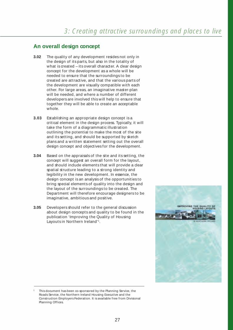
3.05 Developers should refer to the general discussion about design concepts and quality to be found in the publication ‘Improving the Quality of Housing Layouts in Northern Ireland’1.
This document has been co-sponsored by the Planning Service, the Roads Service, the Northern Ireland Housing Executive and the Construction Employers Federation. It is available free from Divisional Planning Offices.
27
1
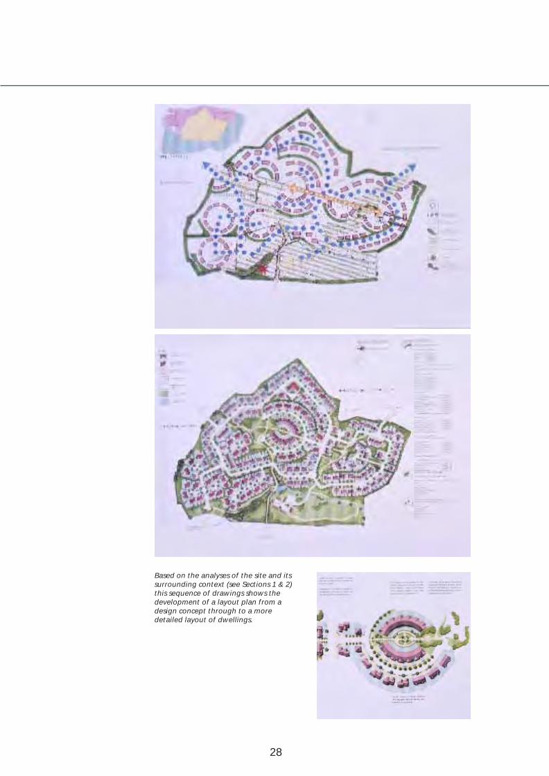
Based on the analyses of the site and its surrounding context (see Sections 1 & 2) this sequence of drawings shows the development of a layout plan from a design concept through to a more detailed layout of dwellings.
28

3: Creating attractive surroundings and places to live
3.06 The presentation of the design concept should include three-dimensional representations. Techniques such as axonometrics, perspectives or photomontage may be used. In addition computer-aided methods can illustrate more fully the three-dimensional character of individual spaces and sequences of spaces.
3.07 Sources of inspiration for design concepts should preferably come from the best designs found in Northern Ireland. Inspiration may also be drawn from high quality designs produced in Great Britain, the Republic of Ireland and the rest of Europe - for many prestigious historic settings did just that. Such design concepts will be welcomed by the Department provided care is taken to reflect the objectives of this guide, and where the end result is justified both by the characteristics of the site and the likely visual impact of the development on the local setting.
Three dimensional representations of design proposals are an important factor in assessing the quality of the development.
29

Contexts for design concepts
Larger developments on green-field sites
3.08 The development of green-field sites located at the edges of settlements in rural settings, particularly the development of larger sites, may allow a wide range of design options and provide opportunities to introduce design innovations that meet the Department’s objectives for sustainability and quality.
3.09 The criteria to be addressed in the design concept will include:
• respect for landform, landscape and history of the site,
• the creation of a distinctive sense of place,
• relationship to existing urban form,
• the provision of open space, tree-lined avenues and local neighbourhood facilities,
• the provision made for walking, cycling and access to public transport,
• the overall permeability and legibility of the layout.
3.10 The Department wishes to encourage developers to take full advantage of such sites - for without the design innovations of the past we would not have today many of the historic settings we now most value.
Low-density areas
3.11 Development in low-density areas, particularly on smaller and infill sites, should aim to provide or reinforce local character and identity and avoid the monotony of suburban sprawl. The design concept should place buildings in a landscape setting and include careful consideration of tree and hedgerow species. Detailed consideration of the spaces to be created, house design and layout will also be necessary. In particular, designs should seek to protect the amenities enjoyed by residents of any
High quality low-density development is existing neighbouring properties.achieved through good house design, andthe retention of existing trees withgenerous levels of new planting.
30
3: Creating attractive surroundings and places to live
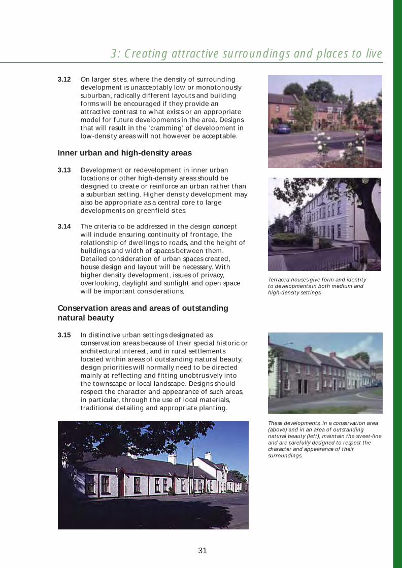
3.12 On larger sites, where the density of surrounding development is unacceptably low or monotonously suburban, radically different layouts and building forms will be encouraged if they provide an attractive contrast to what exists or an appropriate model for future developments in the area. Designs that will result in the ‘cramming’ of development in low-density areas will not however be acceptable.
Inner urban and high-density areas
3.13 Development or redevelopment in inner urban locations or other high-density areas should be designed to create or reinforce an urban rather than a suburban setting. Higher density development may also be appropriate as a central core to large developments on greenfield sites.
3.14 The criteria to be addressed in the design concept will include ensuring continuity of frontage, the relationship of dwellings to roads, and the height of buildings and width of spaces between them. Detailed consideration of urban spaces created, house design and layout will be necessary. With higher density development, issues of privacy, overlooking, daylight and sunlight and open space will be important considerations.
Conservation areas and areas of outstanding natural beauty
3.15 In distinctive urban settings designated as conservation areas because of their special historic or architectural interest, and in rural settlements located within areas of outstanding natural beauty, design priorities will normally need to be directed mainly at reflecting and fitting unobtrusively into the townscape or local landscape. Designs should respect the character and appearance of such areas, in particular, through the use of local materials, traditional detailing and appropriate planting.
Terraced houses give form and identity to developments in both medium and high-density settings.
These developments, in a conservation area (above) and in an area of outstanding natural beauty (left), maintain the street-line and are carefully designed to respect the character and appearance of their surroundings.
31

Housing in a village designed to respect rural character with the buildings enclosing and defining a shared surface space.
Spaces created by buildings and trees in a traditional environment.
3.16 In other areas of attractive village or townscape character, additional design options may be acceptable including the use of contrasting layout arrangements, building forms, components and materials - especially if these would enhance the townscape or landscape by highlighting the existing character.
Villages and small settlements
3.17 The design priorities for development in villages and smaller settlements in rural areas should respect and complement their landscape setting and reflect their essentially rural character in the form, layout and detailing of buildings.
Creating spaces
3.18 The first consideration when producing the design should be the overall quality and character of the spaces being created.
3.19 Although decisions about the layout and location of access routes and parking areas will strongly influence the visual character of the spaces within the development, these should not be the primary determining factors. Designs which incorporate general principles for landscaping and planting, urban design and spatial hierarchy can enhance the quality of the built environment. Developers will be encouraged to employ imaginative design professionals in order to meet the Department’s quality standards.
New high-density terraced housing providing a sense of enclosure.
32

3: Creating attractive surroundings and places to live
Community Facilities
Community Facilities
Schematic diagram showing an interconnected network of streets and avenues where different spaces can be created.
A hierarchy of spaces
3.20 Spaces in inner urban or high-density areas will be determined more by the buildings and layout form than in lower density areas where planting, open spaces and access routes are more influential. The layout of roads and streets will link the spaces created by the buildings and landscape into a legible spatial hierarchy.
A tree lined avenue with verges that might also be a bus route.
Build-outs protect the on-street parking and give the opportunity to plant trees. Traffic calming can be used to create a cycle and pedestrian friendly place.
Direct access to dwellings with well planted front gardens and footways on either side of the road provides a safe and pleasant place for residents.
An enclosed shared surface space where the needs of pedestrians and cyclists take priority over vehicles.
Spaces can be used creatively to help give visual identity to each part of the development, and this potential is indicated in this sequence of sketches. In each, the spaces have a significantly different scale.
33
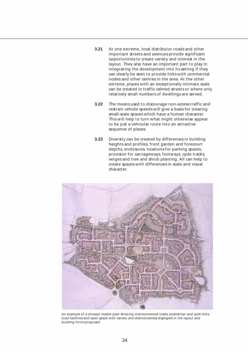
3.21 At one extreme, local distributor roads and other important streets and avenues provide significant opportunities to create variety and interest in the layout. They also have an important part to play in integrating the development into its setting if they can clearly be seen to provide links with commercial nodes and other centres in the area. At the other extreme, places with an exceptionally intimate scale can be created in traffic calmed streets or where only relatively small numbers of dwellings are served.
3.22 The means used to discourage non-access traffic and restrain vehicle speeds will give a basis for creating small-scale spaces which have a human character. This will help to turn what might otherwise appear to be just a vehicular route into an attractive sequence of places.
3.23 Diversity can be created by differences in building heights and profiles, front garden and forecourt depths, enclosures, locations for parking spaces, provision for carriageways, footways, cycle tracks, verges and tree and shrub planting. All can help to create spaces with differences in scale and visual character.
An example of a concept master-plan showing interconnected roads, pedestrian and cycle links, local facilities and open space with variety and distinctiveness displayed in the layout and building forms proposed.
34

3: Creating attractive surroundings and places to live
3.24 The concept master-plan illustrated on the previous page shows sequences of spaces created by the layout design focusing on major visual elements such as existing trees and hedgerows, community buildings and areas of public open space. It illustrates the variety that can be created by sequences of spaces - even in a predominantly low-density development.
Visual contrasts and frontage development
3.25 Clear visual contrasts will be needed to distinguish the spaces created along local distributor roads from those along other kinds of roads. This will help make drivers more aware when they are in surroundings where vehicle speeds have been restrained to promote the safety of pedestrians and cyclists.
3.26 Sterile and unattractive spaces have been created in some recent developments where dwellings have been orientated with their backs onto existing roads. Layouts should be designed to ensure that buildings are located and orientated to present an attractive outlook facing onto all roads, existing and proposed. Specific designs will also be required for buildings occupying internal and external corner sites and this may provide an opportunity to design landmark buildings.
Common and public open spaces
3.27 Too many recent developments have provided little or no public open spaces and those which have been provided are generally in out of the way places without any attempt to make them attractive and useable. Developers should always consider ways of integrating pleasant, attractive and landscaped public open spaces as an intrinsic element of the design to promote quality and meet local needs. A variety of forms of open space should be used to create a recognisable landscape structure for the development located in places where they will be used and valued (see Section 5).
Visual contrasts along different kinds of roads will be necessary.
A semi-detached house design that fronts onto the main road, and also onto the access serving the development.
Well designed terraced houses fronting directly onto the street.
An unattractive visual ‘canyon’ often results where houses back onto rather than front towards roads.
35

New development at the edge of a settlement fitting well into the local landscape setting.
The terraces are well placed fronting onto the road, but the form of development behind fails to respect the local setting and spoils the skyline.
Landmark features
External image of the development
3.28 The overall character of the development may only be apparent when it can be seen from a distance over either buildings or the countryside - and may in itself be a landmark. Considerations will include:
• building heights, skyline shapes, roofline and colour,
• treatment of perimeter edges, whether hard or soft edged,
• ways to exploit attractive views and obscure the unsightly,
• the treatment of open spaces and other site features,
• the treatment of main entrances to the development.
Distinctive public art can be used as a landmark feature.
36
3: Creating attractive surroundings and places to live
Cores and nodal points
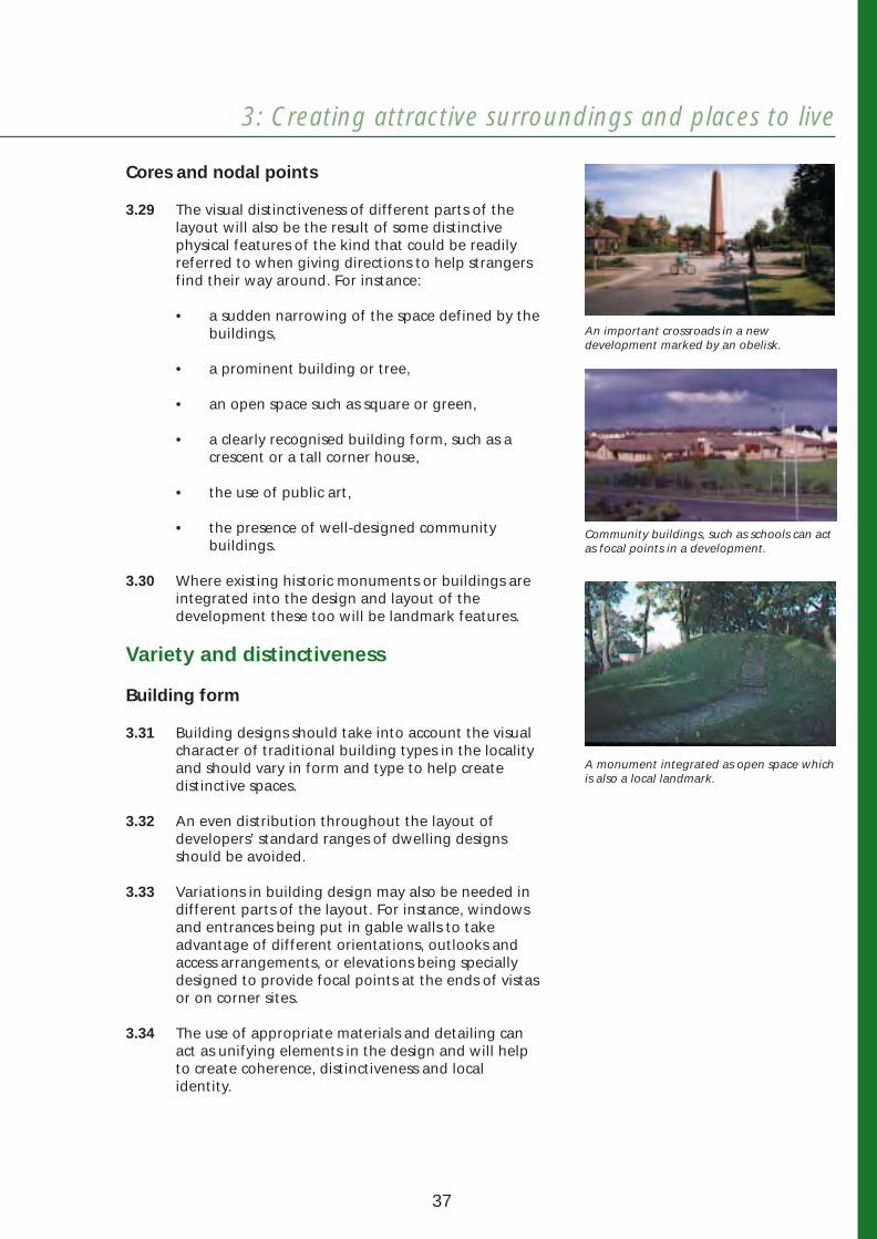
3.29 The visual distinctiveness of different parts of the layout will also be the result of some distinctive physical features of the kind that could be readily referred to when giving directions to help strangers find their way around. For instance:
• a sudden narrowing of the space defined by the buildings,
• a prominent building or tree,
• an open space such as square or green,
• a clearly recognised building form, such as a crescent or a tall corner house,
• the use of public art,
• the presence of well-designed community buildings.
3.30 Where existing historic monuments or buildings are integrated into the design and layout of the development these too will be landmark features.
Variety and distinctiveness
Building form
3.31 Building designs should take into account the visual character of traditional building types in the locality and should vary in form and type to help create distinctive spaces.
3.32 An even distribution throughout the layout of developers’ standard ranges of dwelling designs should be avoided.
3.33 Variations in building design may also be needed in different parts of the layout. For instance, windows and entrances being put in gable walls to take advantage of different orientations, outlooks and access arrangements, or elevations being specially designed to provide focal points at the ends of vistas or on corner sites.
3.34 The use of appropriate materials and detailing can act as unifying elements in the design and will help to create coherence, distinctiveness and local identity.
An important crossroads in a new development marked by an obelisk.
Community buildings, such as schools can act as focal points in a development.
A monument integrated as open space which is also a local landmark.
37
Distinctive details
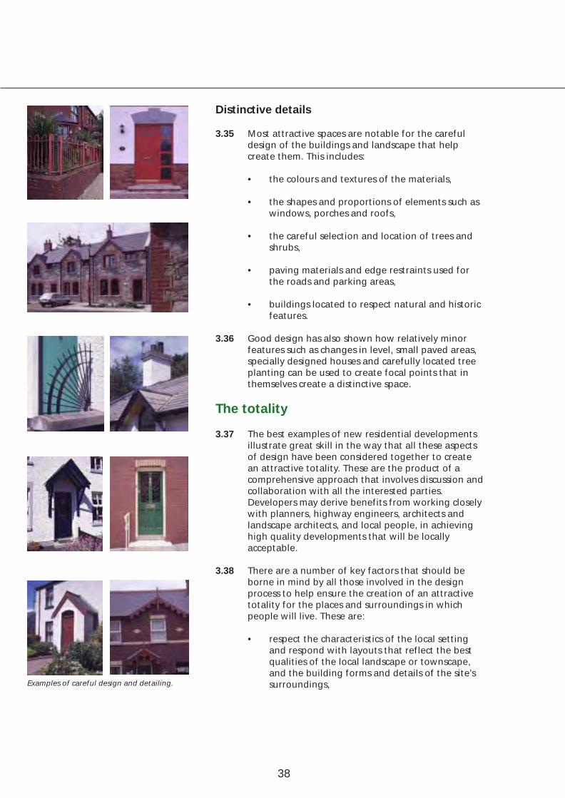
3.35 Most attractive spaces are notable for the careful design of the buildings and landscape that help create them. This includes:
• the colours and textures of the materials,
• the shapes and proportions of elements such as windows, porches and roofs,
• the careful selection and location of trees and shrubs,
• paving materials and edge restraints used for the roads and parking areas,
• buildings located to respect natural and historic features.
3.36 Good design has also shown how relatively minor features such as changes in level, small paved areas, specially designed houses and carefully located tree planting can be used to create focal points that in themselves create a distinctive space.
The totality
3.37 The best examples of new residential developments illustrate great skill in the way that all these aspects of design have been considered together to create an attractive totality. These are the product of a comprehensive approach that involves discussion and collaboration with all the interested parties. Developers may derive benefits from working closely with planners, highway engineers, architects and landscape architects, and local people, in achieving high quality developments that will be locally acceptable.
3.38 There are a number of key factors that should be borne in mind by all those involved in the design process to help ensure the creation of an attractive totality for the places and surroundings in which people will live. These are:
• respect the characteristics of the local setting and respond with layouts that reflect the best qualities of the local landscape or townscape, and the building forms and details of the site’s
Examples of careful design and detailing. surroundings,
38
3: Creating attractive surroundings and places to live
• respect the history of the site and the existing landform,
• aim to create a distinctive sense of place that responds to the local character of the site and it’s setting,
• provide a visually attractive human scale through the layout and density of buildings and the public spaces within,
• retain important vegetation and other natural features, and provide appropriate planting of trees and other plants to encourage biodiversity,
• integrate with existing movement patterns and support walking, cycling and public transport use, rather than just movement by private cars,
• aspire to the highest quality in building form and detail, landscaping and materials used,
• wherever possible, provide a mix of dwelling types and other uses and always strive to create places that will be sustainable, safe and well cared for.
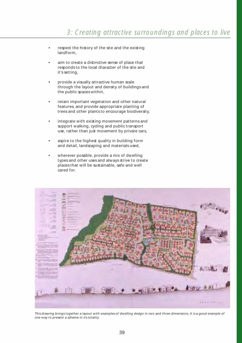
This drawing brings together a layout with examples of dwelling design in two and three dimensions. It is a good example of one way to present a scheme in its totality.
39

40
Creating Places
Part 2
Main elements of design

4 Landscapedesign
The quality of the residential environment will be enhanced by well-considered landscape design. The retention of existing vegetation and new planting can contribute to people’s health, wellbeing and quality of life. It will also increase biodiversity and help raise awareness of, and appreciation for, the environment. This section describes the integration of soft and hard landscape works in the design process.
Main objectives
4.01 Landscape design should be considered as an integral part of the design process, in order to:
• enhance the visual character of the development and encourage the creation of a distinctive sense of place,
• create visual diversity in the layout,
• provide an appropriate setting for developments in a variety of locations,
• integrate public and private open spaces into the design of the development,
• link the development into its wider landscape context,
• improve air quality, reduce pollution and provide a habitat for wildlife.
42

4: Landscape design
Quality in landscape design
4.02 A good, well-considered landscape design is fundamental to the creation of high quality and attractive surroundings that will be satisfying places in which to live. To this end, developers should seek specialist advice from a landscape architect and/or an arboriculturist.
4.03 The Department will expect to see a landscape design that covers the whole site, and that draws from the analyses of the site and its surroundings. This should be based on a landscape report to include:
• principles and aims,
• a survey of the landscape features of the site,
• an analysis of the survey,
• a landscape design based on the findings of the analysis,
• proposals for future management and maintenance.
Existing landscape features
4.04 Mature trees, within or on the boundary of a site, can be a local landmark, support a wide variety of wildlife and have a high landscape value. Younger trees are also important as they will be the visually significant trees of the future. Hedgerows and other natural features, such as streams and ponds, all contribute to the overall character of the site and are important for biodiversity.
4.05 By carefully integrating existing natural features into the development the effect will be a mature landscape framework which, together with new planting proposals, will bring positive benefits to the quality of the environment to be created.
4.06 All existing trees, copses, hedgerows, ponds and other landscape features should be surveyed and recorded. The survey should include:
• accurate dimensional identification on plan (for trees, the girth 1m above ground should be noted together with the tree height and accurate crown spread),
• a health and condition survey together with recommendations,
• identification of the space required for successful retention,
• measures to be taken for protection during development (see Section 13).
A rich mixture of new planting combined with existing mature trees will create a high quality environment.
A stream and associated vegetation well integrated within open space.
43

This layout was carefully designed to enable the retention of mature trees.
Building too close to existing trees can create significant amenity problems. These trees have now been removed.
High quality soft landscape works in an open space area.
4.07 In certain cases, the estimated mature heights and spreads of existing trees, in relation to proposed buildings, may be required to be shown accurately on plans and sections.
4.08 Developers should demonstrate that their design proposals have taken proper account of the need to safeguard existing landscape features. Where trees are to be retained they will require sufficient space if they are to thrive. The design should also consider the impact of changes of level within the site on existing natural features.
4.09 In order to avoid damage to the root systems and drainage of existing trees, development should be kept outside the crown spread or half the height of the trees, whichever is the greater. This is a minimum standard and in many instances it will be necessary to maintain a greater separation distance between existing trees and buildings. This will help ensure their long-term retention, and can also help prevent potential amenity problems that may arise for residents of properties, such as loss of light or leaf fall due to proximity to trees. In some cases, it may be appropriate to keep development outside the falling distance of mature trees.
4.10 Existing landscape features may be subject to statutory protection and developers must obtain the necessary consent before work is begun. Even where consent is obtained, damage caused through inappropriate working practices could result in prosecution. Developers are therefore advised to seek professional advice from a landscape architect and/or an arboriculturist.
Soft landscape works
4.11 Tree planting and other soft landscape works will be an important aspect of development in all locations, and especially for public and private open spaces. They will be a dominant feature in the design of green-field sites and development in low-density areas, and can complement hard landscape works in high-density developments and on inner urban sites. In particular, tree planting and soft landscape works may be needed to help:
• reinforce and enhance existing natural features, and integrate the development into the surrounding landscape,
• denote the urban/rural fringe,
• create variety through seasonal changes in foliage,
44

4: Landscape design
• soften the visual impact of parked cars, garden walls and fences and large areas of paving,
• provide a visual contrast to buildings, and shield unsightliness,
• emphasise main access routes,
• provide privacy,
• enhance open spaces,
• create a focal point at a change in direction, and add interest to a vehicular, pedestrian or cycle route.
4.12 The provision of tree-lined avenues along local distributor roads and other important streets will be particularly important in promoting a quality environment and helping to create distinctiveness within the development.
4.13 Landscape schemes should provide a hierarchy of different types of planting throughout the development encompassing:
• structure/boundary planting,
• amenity planting,
• street trees,
• garden trees and hedgerow planting,
• specimen trees.
4.14 Aspects of planting such as potential height, shape, leaf form and colouring may all play a part in contributing to the overall distinctiveness and character of the place being created. Care will be needed to select appropriate species (see Section 13).
4.15 The species selected must take into account the characteristics of the site and should normally be native to Northern Ireland and the locality of the development. Within the development there may be scope for some non-native specimen trees, for example, in the choice of street tree or as specimens grown in a garden. However, inappropriate choice can severely detract from the landscape and visual character of an area. For instance, the extensive use of ornamental conifers as boundary features are neither ecologically nor visually acceptable.
Well considered planting adds quality, whatever the density of the development.
45
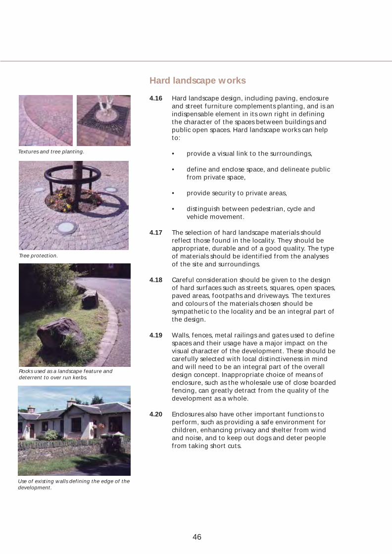
Textures and tree planting.
Tree protection.
Rocks used as a landscape feature and deterrent to over run kerbs.
Use of existing walls defining the edge of the development.
Hard landscape works
4.16 Hard landscape design, including paving, enclosure and street furniture complements planting, and is an indispensable element in its own right in defining the character of the spaces between buildings and public open spaces. Hard landscape works can help to:
• provide a visual link to the surroundings,
• define and enclose space, and delineate public from private space,
• provide security to private areas,
• distinguish between pedestrian, cycle and vehicle movement.
4.17 The selection of hard landscape materials should reflect those found in the locality. They should be appropriate, durable and of a good quality. The type of materials should be identified from the analyses of the site and surroundings.
4.18 Careful consideration should be given to the design of hard surfaces such as streets, squares, open spaces, paved areas, footpaths and driveways. The textures and colours of the materials chosen should be sympathetic to the locality and be an integral part of the design.
4.19 Walls, fences, metal railings and gates used to define spaces and their usage have a major impact on the visual character of the development. These should be carefully selected with local distinctiveness in mind and will need to be an integral part of the overall design concept. Inappropriate choice of means of enclosure, such as the wholesale use of close boarded fencing, can greatly detract from the quality of the development as a whole.
4.20 Enclosures also have other important functions to perform, such as providing a safe environment for children, enhancing privacy and shelter from wind and noise, and to keep out dogs and deter people from taking short cuts.
46

4: Landscape design
Landscape management and maintenance
4.21 The continuing management and maintenance of a landscape scheme is important to ensure the successful establishment of new planting and the long-term care and protection of the whole scheme.
4.22 Developers should therefore draw up schedules of work, at an early stage in the design, for the protection of existing vegetation to be retained and the establishment of new planting, together with a long-term plan for the management of the overall landscape scheme. This should normally cover a period of 20 years and include performance indicators at critical stages in the growth of the new and existing planting.
4.23 Developers will be responsible for the implementation of all landscape works and the provision of on-going management and maintenance, unless this responsibility is transferred to another appropriate body to be agreed with the Department.
Thought needs to be given to the continuing maintenance of landscape provision.
Successful landscape design often combines a good use of both soft and hard landscape works.
47
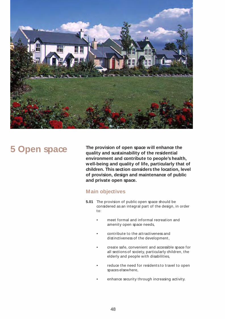
5 Open space The provision of open space will enhance the quality and sustainability of the residential environment and contribute to people’s health, well-being and quality of life, particularly that of children. This section considers the location, level of provision, design and maintenance of public and private open space.
Main objectives
5.01 The provision of public open space should be considered as an integral part of the design, in order to:
• meet formal and informal recreation and amenity open space needs,
• contribute to the attractiveness and distinctiveness of the development,
• create safe, convenient and accessible space for all sections of society, particularly children, the elderly and people with disabilities,
• reduce the need for residents to travel to open spaces elsewhere,
• enhance security through increasing activity.
48

5: Open space
5.02 The provision of adequate private open space should also be considered as an integral part of the design in order to:
• provide for residents’ amenity,
• enhance visual attractiveness,
• enhance safety, especially for young children.
Public open space
5.03 Public open space can be provided in a variety of forms including: equipped play areas for young children; informal kickabout areas; formal playing fields; village greens and small parks; natural surroundings and amenity planting. Where practicable spaces should be designed to be multi-functional.
Level of provision
5.04 The amount of public open space required in any development will be negotiated with developers according to the specific characteristics of the development, the site and its context, having regard to the Department’s policy requirements. A normal expectation for new green-field development may be around 10% of the site area or greater.
Green-field sites and low-density areas
5.05 Public open spaces should not be located out of sight at the ends of rear gardens. They should be well-distributed in a comprehensive way, linked together, and designed as an integral part of the overall layout.
5.06 Larger open spaces can be major focal points along local distributor roads and other important streets and avenues and can create settings for key community buildings. They also provide opportunities to integrate archaeological remains, existing mature trees and other natural features such as streams and rivers.
5.07 Smaller open spaces can provide minor focal points and should normally be separated from houses by roads designed to restrain vehicle speeds.
5.08 To reduce the risk of crime, open spaces should be directly overlooked by the fronts of dwellings and can also have informal surveillance provided by drivers and cyclists using carriageways and cycle tracks. However, it is also important that open spaces should be located and designed to minimise the risks of nuisances to those living nearby.
Children’s play space.
A good example of housing overlooking an informal green space.
New green-field developments should include open space that is useable - here the open space creates a focal point and is large enough to be used as a kickabout.
Notional layout showing open space used as focal points.
49

A quiet space close to sheltered housing.
An urban square set in a mixed-use development of shops and flats.
A well landscaped open space with walls used as a resting place.
5.09 Dwellings specifically designed for elderly people should be located away from equipped children’s play spaces and other places in the layout where young people are likely to congregate. Such households may however benefit from the provision of appropriately designed informal spaces that can act as meeting places.
Inner urban and high-density areas
5.10 In inner urban locations and other high-density areas, potential open space provision is likely to be more limited. Small squares or formal spaces should be considered, but it is likely in many cases that streets and parking areas may become the focus of design. These should not only accommodate circulation patterns, but also outdoor activities including resting places and small play areas for children. To achieve quality, design considerations should include:
• street width, alignment, quality of space,
• traffic calming design,
• street planting,
• lighting, signage, street furniture (such as bus stops, benches and litter bins),
• paving and surface textures.
Maintenance
5.11 Individual areas of public open space should be of a sufficient size and designed in detail to allow for economical maintenance. Footpaths and cycle tracks crossing open spaces should be more direct and convenient to use than planted areas.
5.12 The Department will not adopt areas of public open space. Responsibility for the provision, landscaping and subsequent maintenance of these spaces after completion, will rest with the developer. This matter should therefore be discussed at an early stage in the design process with the Department.
5.13 Developers may wish to consider transferring the land to the local district council or a charitable trust, or setting up a management company to administer and maintain such areas.
50

5: Open space
Routes for movement
Roads and footways
5.14 Residents meet each other and children play informally in streets and along roads. These routes can provide circuits for adults to go jogging, parents to take young children for walks and for children on bicycles. To make such routes attractive and safer for people to use:
• trees should be planted,
• carriageways should be designed to restrain vehicle speeds,
• tree-lined verges should be used to separate footways and cycle tracks from local distributor roads,
• footways should, on occasion, be made to vary in width to provide more space than the minimum that would be required simply for access.
Footpaths and cycle tracks
5.15 Where footpath and cycle track links are provided there should be sufficient additional space alongside these to accommodate planting and to provide for activities other than access.
Shared surfaces
5.16 Footways may be omitted where it is desirable to create a shared surface with an intimate human scale suitable for use by pedestrians, cyclists and vehicles. The overall design and surface treatment of such areas should however make clear to drivers that they are in an area where the needs of pedestrians and cyclists will take priority.
Private open space
5.17 Well-designed space around buildings can add greatly to the attractiveness of the development, particularly where the principles of defensible space are applied. The design should therefore make adequate provision for private open space in the form of gardens, patios, balconies or terraces for all dwellings.
A large tree planted in the middle of a housing square in the Netherlands.
Well landscaped footpath and cycle track in the Netherlands providing an informal link between housing areas.
A shared surface housing square providing a safe place for children at play.
51

A good sized back garden gives space for children to play safely.
5.18 At lower densities a variety of garden sizes and other useable private open spaces can promote diversity and create choice for potential residents. At higher densities private open space for apartments, maisonettes or small groups of houses may be provided in the form of privately maintained communal gardens. These can create focal points in the layout and provide effective space to contrast with the high-density buildings.
Level of private open space provision
5.19 On green-field sites and in lower density developments all houses should have an area of private open space behind the building line. The overall design concept for the development will determine the setting for houses, including the level of private back garden provision. To promote choice for residents a variety of different garden sizes should be provided and back garden provision should therefore be calculated as an average space standard for the development as a whole, and should be around 70 sq m per house or greater. Garden sizes larger than the average will generally suit dwellings designed for use by families, while smaller areas will be more appropriate for houses with 1 or 2 bedrooms or houses located opposite or adjacent to public or communal open space. For any individual house however an area less than around 40 sq m will generally be unacceptable.
5.20 In the case of apartment or flat developments, or 1 and 2 bedroomed houses on small urban infill sites, private communal open space will be acceptable in the form of landscaped areas, courtyards or roof gardens. These should range from a minimum of 10 sq m per unit to around 30 sq m per unit. The appropriate level of provision should be determined by having regard to the particular context of the development and the overall design concept. Generally developments in inner urban locations and other high-density areas will tend towards the lower figure. Apartment developments on green-field sites and within lower density areas should normally seek to provide the higher figure, although this may be reduced where some private open space is provided in the form of patios or balconies.
52
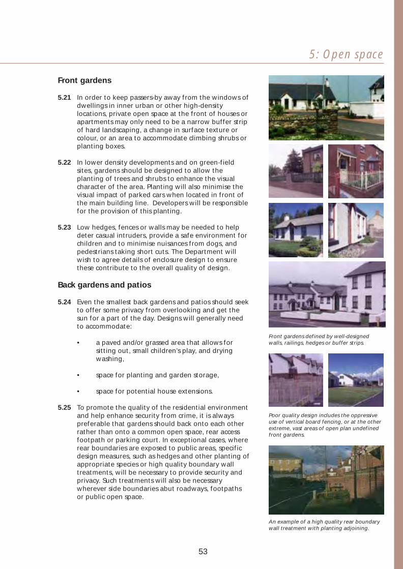
5: Open space
Front gardens
5.21 In order to keep passers-by away from the windows of dwellings in inner urban or other high-density locations, private open space at the front of houses or apartments may only need to be a narrow buffer strip of hard landscaping, a change in surface texture or colour, or an area to accommodate climbing shrubs or planting boxes.
5.22 In lower density developments and on green-field sites, gardens should be designed to allow the planting of trees and shrubs to enhance the visual character of the area. Planting will also minimise the visual impact of parked cars when located in front of the main building line. Developers will be responsible for the provision of this planting.
5.23 Low hedges, fences or walls may be needed to help deter casual intruders, provide a safe environment for children and to minimise nuisances from dogs, and pedestrians taking short cuts. The Department will wish to agree details of enclosure design to ensure these contribute to the overall quality of design.
Back gardens and patios
5.24 Even the smallest back gardens and patios should seek to offer some privacy from overlooking and get the sun for a part of the day. Designs will generally need to accommodate:
• a paved and/or grassed area that allows for sitting out, small children’s play, and drying washing,
• space for planting and garden storage,
• space for potential house extensions.
5.25 To promote the quality of the residential environment and help enhance security from crime, it is always preferable that gardens should back onto each other rather than onto a common open space, rear access footpath or parking court. In exceptional cases, where rear boundaries are exposed to public areas, specific design measures, such as hedges and other planting of appropriate species or high quality boundary wall treatments, will be necessary to provide security and privacy. Such treatments will also be necessary wherever side boundaries abut roadways, footpaths or public open space.
53
Front gardens defined by well-designed walls, railings, hedges or buffer strips.
Poor quality design includes the oppressive use of vertical board fencing, or at the other extreme, vast areas of open plan undefined front gardens.
An example of a high quality rear boundary wall treatment with planting adjoining.

Private communal gardens
5.26 Apart from the provision of sitting out areas, the design of communal gardens may need to include space for activities such as children’s play and formal and informal recreation. Such areas should be enclosed in an appropriate manner to deter intruders and make their private character clear.
Maintenance
5.27 Responsibility for the provision, landscaping and subsequent maintenance of private communal spaces, after completion, will rest with the developer. This matter should therefore be discussed at an early stage in the design process with the Department. Developers may wish to consider the setting up of a management company to administer and maintain
Attractive private communal gardens such areas. providing an effective contrast with the adjacent high-density apartments.
54

5: Open space
55
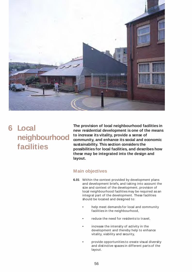
6 Local neighbourhood facilities
The provision of local neighbourhood facilities in new residential development is one of the means to increase its vitality, provide a sense of community, and enhance its social and economic sustainability. This section considers the possibilities for local facilities, and describes how these may be integrated into the design and layout.
Main objectives
6.01 Within the context provided by development plans and development briefs, and taking into account the size and context of the development, provision of local neighbourhood facilities may be required as an integral part of the development. These facilities should be located and designed to:
• help meet demands for local and community facilities in the neighbourhood,
• reduce the need for residents to travel,
• increase the intensity of activity in the development and thereby help to enhance vitality, viability and security,
• provide opportunities to create visual diversity and distinctive spaces in different parts of the layout.
56
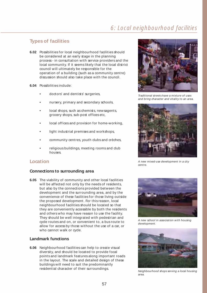
6: Local neighbourhood facilities
Types of facilities
6.02 Possibilities for local neighbourhood facilities should be considered at an early stage in the planning process - in consultation with service providers and the local community. If it seems likely that the local district council will ultimately be responsible for the operation of a building (such as a community centre) discussion should also take place with the council.
6.04 Possibilities include:
• doctors’ and dentists’ surgeries,
• nursery, primary and secondary schools,
• local shops, such as chemists, newsagents, grocery shops, sub-post offices etc,
• local offices and provision for home-working,
• light industrial premises and workshops,
• community centres, youth clubs and crèches,
• religious buildings, meeting rooms and club houses.
Location
Connections to surrounding area
6.05 The viability of community and other local facilities will be affected not only by the needs of residents, but also by the connections provided between the development and the surrounding area, and by the convenience of these facilities for those living outside the proposed development. For this reason, local neighbourhood facilities should be located so that they are conveniently accessible by both the residents and others who may have reason to use the facility. They should be well integrated with pedestrian and cycle routes and on, or convenient to, a bus route to allow for access by those without the use of a car, or who cannot walk or cycle.
Landmark functions
6.06 Neighbourhood facilities can help to create visual diversity, and should be located to provide focal points and landmark features along important roads in the layout. The scale and detailed design of these buildings will need to suit the predominantly residential character of their surroundings.
57
Traditional streets have a mixture of uses and bring character and vitality to an area.
A new mixed-use development in a city centre.
A new school in association with housing development.
Neighbourhood shops serving a local housing area.

Nuisances
6.07 Certain local facilities or community buildings may cause nuisance to residents living nearby. Also, parking provision for these places and facilities such as doctors’ surgeries can generate noise and other disturbance. Consequently, the entrances and parking areas of all community buildings should be conveniently accessible but located well away from dwellings. Buildings that are likely to generate the greatest noise nuisance should be designed to provide insulation as a part of the building structure and parking areas should be well separated from dwellings by an area of planting or common open space.
Community buildings will add value to a development, but care must be taken in design to minimise any noise or nuisance that might be caused.
58

6: Local neighbourhood facilities
59
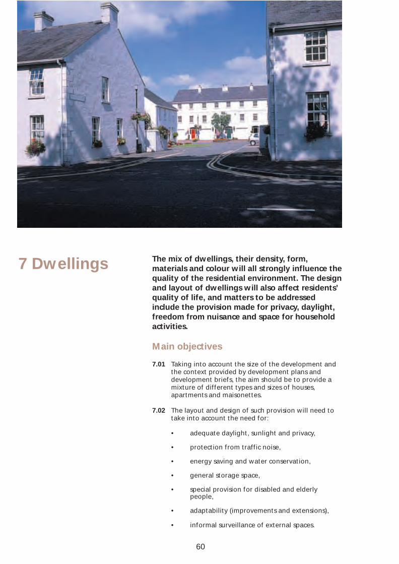
7 Dwellings The mix of dwellings, their density, form, materials and colour will all strongly influence the quality of the residential environment. The design and layout of dwellings will also affect residents’ quality of life, and matters to be addressed include the provision made for privacy, daylight, freedom from nuisance and space for household activities.
Main objectives
7.01 Taking into account the size of the development and the context provided by development plans and development briefs, the aim should be to provide a mixture of different types and sizes of houses, apartments and maisonettes.
7.02 The layout and design of such provision will need to take into account the need for:
• adequate daylight, sunlight and privacy,
• protection from traffic noise,
• energy saving and water conservation,
• general storage space,
• special provision for disabled and elderly people,
• adaptability (improvements and extensions),
• informal surveillance of external spaces.
60

7: Dwellings
Dwelling mix
7.03 A mixture of different types and sizes of houses, apartments and maisonettes may be needed to:
• create a balanced community in the local area,
• provide choice within the development,
• allow building densities to be increased,
• make use of awkwardly shaped parts of the site,
• create visual variety and interest.
7.04 Developers should examine the need to include an element of affordable housing in their plans where a social need is identified.
7.05 Any need to provide special accommodation for elderly or disabled people should also be examined with the relevant local authorities at the early planning stage.
7.06 Proposals for dwellings designed specifically to provide for home working will be considered sympathetically by the Department provided they are an integral part of the design and will not be detrimental to the amenity of others.
A variety of dwelling forms and types detached, semi-detached or terraced; two storey, three storey or more - and a mix of private and public is desirable.
61
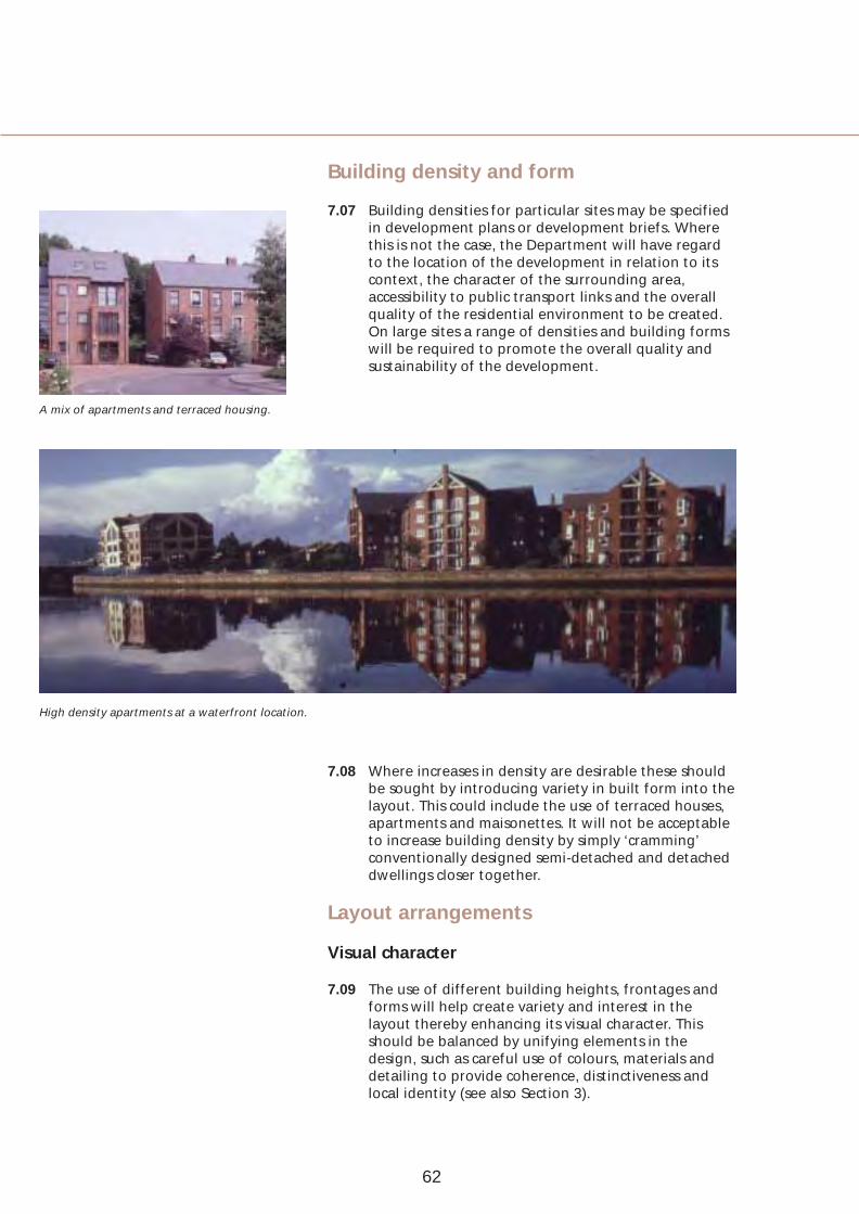
A mix of apartments and terraced housing.
Building density and form
7.07 Building densities for particular sites may be specified in development plans or development briefs. Where this is not the case, the Department will have regard to the location of the development in relation to its context, the character of the surrounding area, accessibility to public transport links and the overall quality of the residential environment to be created. On large sites a range of densities and building forms will be required to promote the overall quality and sustainability of the development.
High density apartments at a waterfront location.
7.08 Where increases in density are desirable these should be sought by introducing variety in built form into the layout. This could include the use of terraced houses, apartments and maisonettes. It will not be acceptable to increase building density by simply ‘cramming’ conventionally designed semi-detached and detached dwellings closer together.
Layout arrangements
Visual character
7.09 The use of different building heights, frontages and forms will help create variety and interest in the layout thereby enhancing its visual character. This should be balanced by unifying elements in the design, such as careful use of colours, materials and detailing to provide coherence, distinctiveness and local identity (see also Section 3).
62
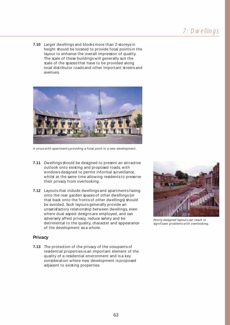
7: Dwellings
7.10 Larger dwellings and blocks more than 2-storeys in height should be located to provide focal points in the layout to enhance the overall impression of quality. The scale of these buildings will generally suit the scale of the spaces that have to be provided along local distributor roads and other important streets and avenues.
A circus with apartments providing a focal point in a new development.
7.11 Dwellings should be designed to present an attractive outlook onto existing and proposed roads, with windows designed to permit informal surveillance, whilst at the same time allowing residents to preserve their privacy from overlooking.
7.12 Layouts that include dwellings and apartments facing onto the rear garden spaces of other dwellings (or that back onto the fronts of other dwellings) should be avoided. Such layouts generally provide an unsatisfactory relationship between dwellings, even where dual aspect designs are employed, and can adversely affect privacy, reduce safety and be detrimental to the quality, character and appearance of the development as a whole.
Privacy
7.13 The protection of the privacy of the occupants of residential properties is an important element of the quality of a residential environment and is a key consideration where new development is proposed adjacent to existing properties.
Poorly designed layouts can result in significant problems with overlooking.
63

7.14 Well-designed layouts should, wherever possible, seek to minimise overlooking between dwellings and provide adequate space for privacy. The amount of space considered appropriate will vary according to the location, context and characteristics of the site, and will generally be set by the overall design concept for the development.
7.15 On green-field sites and in low-density developments, good practice indicates that a separation distance of around 20m or greater between the opposing rear first floor windows of new houses is generally acceptable. Consideration may, however, be given to a smaller separation distance in order to meet the overall quality objectives set out in the design concept for the development, or in cases where it is important to reflect traditional building forms in the locality. Where smaller separation distances are employed, the design should include mitigating measures to help promote privacy - for example, through the location of bathrooms and the use of high level windows on upper floors to minimise the overlooking of living room windows and gardens of buildings opposite. A smaller separation distance will generally also be acceptable for single-storey development.
7.16 Where the development abuts the private garden areas of existing properties, a separation distance greater than 20m will generally be appropriate to minimise overlooking, with a minimum of around 10m between the rear of new houses and the common boundary. An enhanced separation distance may also be necessary for development on sloping sites.
7.17 Great care will be needed in designs where new residential schemes, such as apartments, include living rooms or balconies on upper floors as this can cause a significant loss of amenity to adjoining dwellings, particularly where they are close to the boundaries of existing properties. Where such development is proposed on green-field sites or in lower density areas, good practice indicates that a separation distance of around 30m should be observed or, alternatively, consideration given to a modified design. Where such development abuts the private garden areas of existing properties, a minimum distance of around 15m should be provided between the rear of the apartments and the common boundary.
64

7: Dwellings
7.18 Greater flexibility will generally be appropriate in assessing the separation distance for apartments and infill housing schemes in inner urban locations or other higher density areas. This matter should be appropriately addressed in the overall design concept for the development, but schemes likely to result in a significant loss of privacy or overlooking, particularly of existing properties, will not be acceptable.
7.19 To give privacy to adjacent dwellings and gardens, an appropriately designed boundary treatment, such as a hedge, or wall, that is above eye level in height (or a set-back in the building line) should be provided for a distance of around 3m from the back of the house. It will also be desirable for the design to indicate an appropriate boundary treatment, generally above eye level in height, at the ends of abutting back gardens.
7.20 There should always be a strong definition between private open spaces and public areas, for example, where the side garden of a dwelling abuts a road, footpath or common open space. High quality boundary treatments, such as hedges or well-designed walls will be necessary in such cases to promote the quality of the residential environment (see also Section 4).
Daylight and sunlight
7.21 Layouts and dwellings should be planned to provide acceptable levels of daylight into interiors. The building spacing required for privacy will normally ensure a satisfactory level of daylight and an acceptable minimum amount of sunlight.
7.22 The layout should ensure that sufficent space is provided between dwellings and existing trees to be retained to prevent problems with overshadowing, while new planting close to buildings should be deciduous to allow access for sunlight and daylight during the winter.
7.23 To promote energy efficiency, consideration should be given to the orientation of dwellings in order that living rooms can benefit from passive solar gain.
65
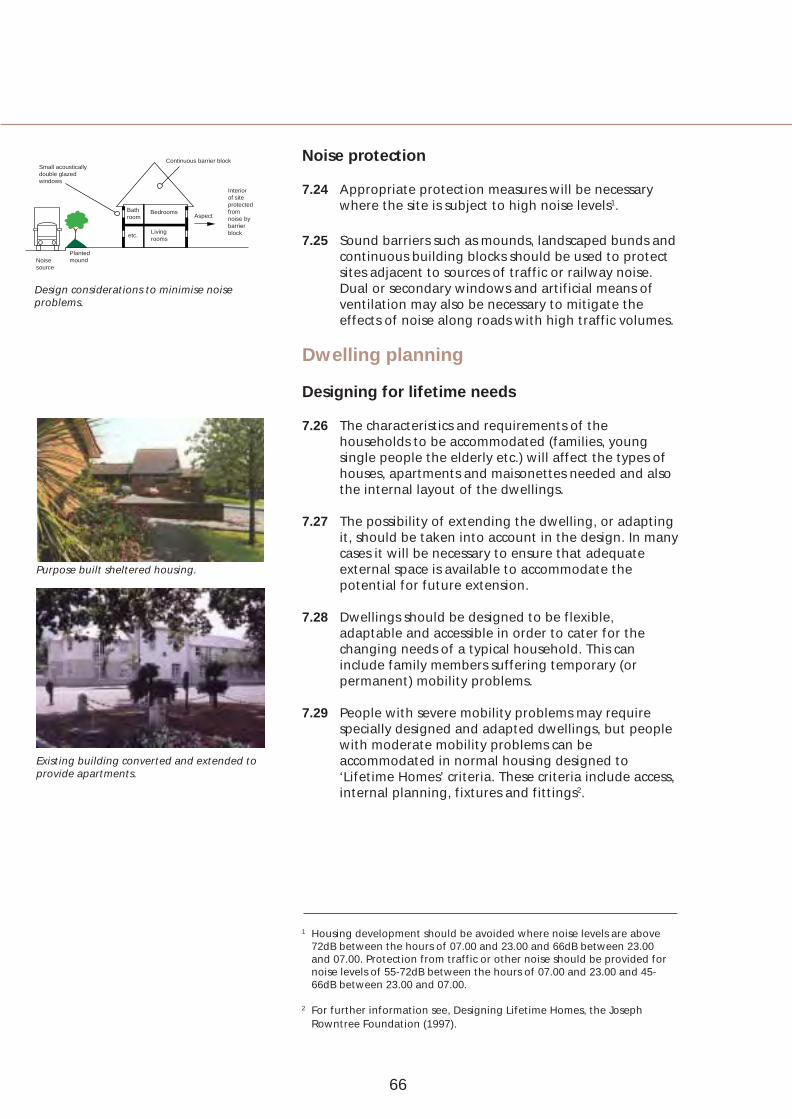
Small acoustically double glazed windows
Bath room
Bedrooms
etc. Living rooms
Aspect
Interior of site protected from noise by barrier block
Noise Planted mound
Noise protection Continuous barrier block
7.24 Appropriate protection measures will be necessary where the site is subject to high noise levels1.
7.25 Sound barriers such as mounds, landscaped bunds and continuous building blocks should be used to protect
source sites adjacent to sources of traffic or railway noise. Design considerations to minimise noise Dual or secondary windows and artificial means of problems. ventilation may also be necessary to mitigate the
effects of noise along roads with high traffic volumes.
Dwelling planning
Designing for lifetime needs
7.26 The characteristics and requirements of the households to be accommodated (families, young single people the elderly etc.) will affect the types of houses, apartments and maisonettes needed and also the internal layout of the dwellings.
7.27 The possibility of extending the dwelling, or adapting it, should be taken into account in the design. In many cases it will be necessary to ensure that adequate external space is available to accommodate the potential for future extension.
7.28 Dwellings should be designed to be flexible, adaptable and accessible in order to cater for the changing needs of a typical household. This can include family members suffering temporary (or permanent) mobility problems.
7.29 People with severe mobility problems may require specially designed and adapted dwellings, but people with moderate mobility problems can be accommodated in normal housing designed to ‘Lifetime Homes’ criteria. These criteria include access, internal planning, fixtures and fittings2.
Purpose built sheltered housing.
Existing building converted and extended to provide apartments.
1 Housing development should be avoided where noise levels are above 72dB between the hours of 07.00 and 23.00 and 66dB between 23.00 and 07.00. Protection from traffic or other noise should be provided for noise levels of 55-72dB between the hours of 07.00 and 23.00 and 4566dB between 23.00 and 07.00.
2 For further information see, Designing Lifetime Homes, the Joseph Rowntree Foundation (1997).
66
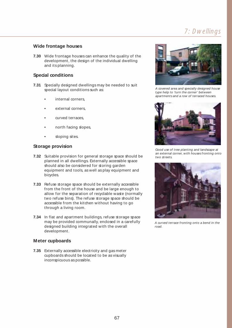
7: Dwellings
Wide frontage houses
7.30 Wide frontage houses can enhance the quality of the development, the design of the individual dwelling and its planning.
Special conditions
7.31 Specially designed dwellings may be needed to suit special layout conditions such as:
• internal corners,
• external corners,
• curved terraces,
• north facing slopes,
• sloping sites.
Storage provision
7.32 Suitable provision for general storage space should be planned in all dwellings. Externally accessible space should also be considered for storing garden equipment and tools, as well as play equipment and bicycles.
7.33 Refuse storage space should be externally accessible from the front of the house and be large enough to allow for the separation of recyclable waste (normally two refuse bins). The refuse storage space should be accessible from the kitchen without having to go through a living room.
7.34 In flat and apartment buildings, refuse storage space may be provided communally, enclosed in a carefully designed building integrated with the overall development.
Meter cupboards
7.35 Externally accessible electricity and gas meter cupboards should be located to be as visually inconspicuous as possible.
A covered area and specially designed house type help to ‘turn the corner’ between apartments and a row of terraced houses.
Good use of tree planting and landscape at an external corner, with houses fronting onto two streets.
A curved terrace fronting onto a bend in the road.
67

8 Pedestrian and cycle routes
Increasing emphasis in government policy is placed on promoting walking and cycling for short journeys, rather than reliance on the car. This section describes provision for pedestrians and cyclists designed to encourage more sustainable modes of travel.
Main objectives
8.01 To help reduce the use of cars and encourage walking and cycling, and provide links to public transport, the routes provided for pedestrians and cyclists should be laid out and designed to:
• be as direct as practicable in relation to local facilities, bus stops and railway halts,
• provide attractive routes and accommodate conveniently and safely the numbers of pedestrians and cyclists likely to use the routes,
• help minimise the hazards associated with vehicular traffic,
• help enhance the visual character of the development by providing space for planting,
• have the easiest practicable gradients (taking into account the special needs of people whose mobility is impaired).
68

8: Pedestrian and cycle routes
8.02 Footpaths and cycle tracks should be provided where this would create safer and more convenient routes than footways and carriageways.
8.03 Where only a limited number of vehicular access points to the site are available, the possibility of providing additional accesses for the sole use of pedestrians and cyclists should be considered.
Footways
8.04 Where carriageways provide an interconnected network of vehicular routes, footways alongside carriageways will generally create a sufficiently convenient and safe environment to cater for pedestrian movement.
8.05 Footways should normally be provided along both sides of the carriageway. One footway may be omitted for single-sided development. In such cases a crossing point may, however, be needed to ensure continuity where a major pedestrian desire line crosses the carriageway.
8.06 Footways may also be omitted in order to create a shared surface, provided the carriageway serves no more than around 25 dwellings - or 50 dwellings for looped or through roads where junctions with roads with footways are located at each end of the shared surface. Requirements for the detailed design of shared surfaces are set out in Section 19.
8.07 To promote the provision of tree-lined avenues, consideration should always be given to the potential for planting of appropriate street trees in footways. This will help to enhance the surroundings and provide visual diversity in the spaces created along carriageways (see also Paragraph 8.15).
Footways on both sides of the road with trees forming an avenue.
One footway omitted with single sided development fronting towards an attractive planted verge.
No footways - a shared surface housing square.
69

Safe and attractive routes will help to promote cycling.
A tree-lined street, cycle track and footway in an existing area.
Use of verges can enhance the development and the safety of pedestrians and cyclists.
Cycle tracks
8.08 The layout should be designed to provide clear, coherent and attractive routes for cyclists in order to encourage cycling, including cycling by unaccompanied children of 12 years and upward.
8.09 Cycle tracks segregated from footways should be provided alongside local distributor roads. Cycle tracks should also be provided:
• in association with any footpath routes in the development in order to enhance convenience for cyclists,
• to connect with, or be a part, of any wider cycle route provision, existing or proposed,
• to serve places generating significant numbers of cyclists (such as schools or other local facilities).
8.10 In the interests of safety, special care will be necessary in the design of the layout where cycle tracks cross carriageways and it will normally be necessary to provide priority for cyclists at junctions. At all cycle crossing points the relevant priority will need to be clearly marked.
8.11 Elsewhere within the development, provision for cycling will, to a large extent, be accommodated by traffic calmed streets which have been designed to take account of the needs, safety, comfort and convenience of cyclists.
Verges
8.12 Verges will enhance the safety of pedestrians and cyclists within the development, and they should normally be planted with street trees in order to promote quality and help create distinctive spaces.
8.13 Footways and cycle tracks should be separated from carriageways by verges along local distributor roads and outside schools and similar places where young children congregate. Verges should also be provided where:
• footways alone would not provide the sight lines necessary at bends and junctions,
• footways are not provided and sight lines must be safeguarded,
• footways or carriageways cannot accommodate services underground and associated surface equipment.
70
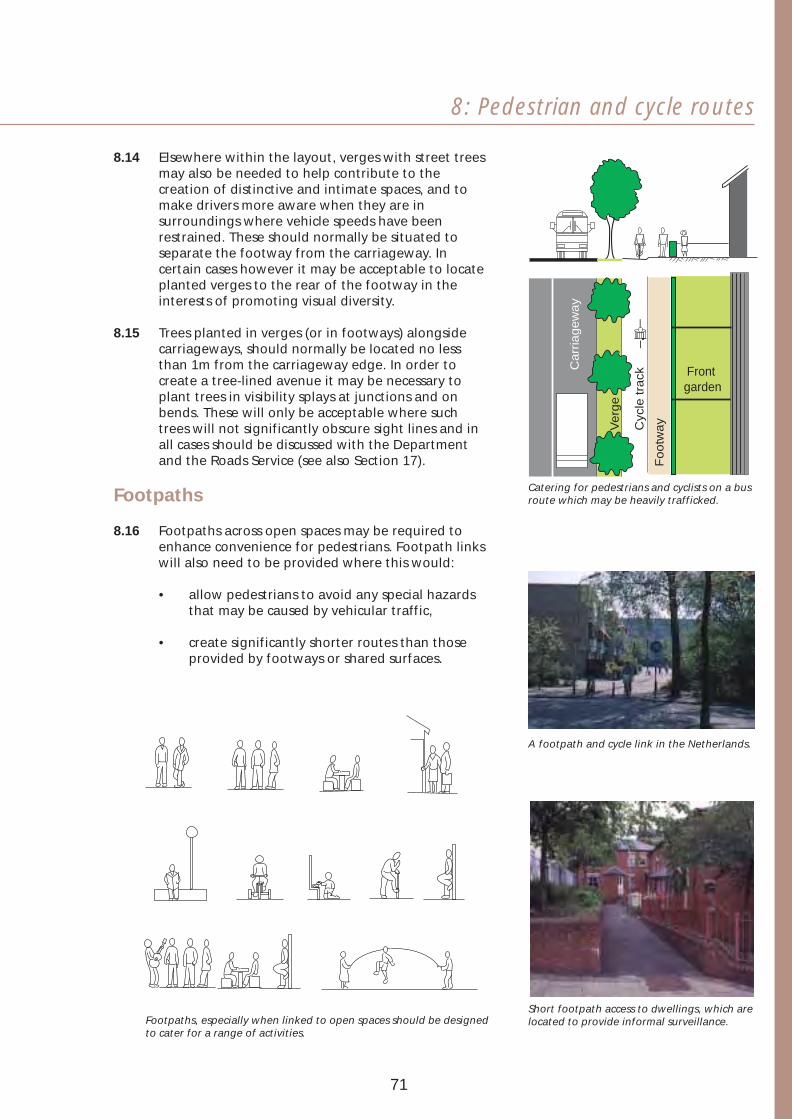
8: Pedestrian and cycle routes
8.14 Elsewhere within the layout, verges with street trees may also be needed to help contribute to the creation of distinctive and intimate spaces, and to make drivers more aware when they are in surroundings where vehicle speeds have been restrained. These should normally be situated to separate the footway from the carriageway. In certain cases however it may be acceptable to locate planted verges to the rear of the footway in the interests of promoting visual diversity.
8.15 Trees planted in verges (or in footways) alongside carriageways, should normally be located no less than 1m from the carriageway edge. In order to create a tree-lined avenue it may be necessary to plant trees in visibility splays at junctions and on bends. These will only be acceptable where such trees will not significantly obscure sight lines and in all cases should be discussed with the Department and the Roads Service (see also Section 17).
Front garden
Cyc
le t
rack
Ve
rge
Fo
otw
ay
Ca
rria
ge
wa
y
Catering for pedestrians and cyclists on a busFootpaths route which may be heavily trafficked.
8.16 Footpaths across open spaces may be required to enhance convenience for pedestrians. Footpath links will also need to be provided where this would:
• allow pedestrians to avoid any special hazardsthat may be caused by vehicular traffic,
• create significantly shorter routes than thoseprovided by footways or shared surfaces.
Footpaths, especially when linked to open spaces should be designedto cater for a range of activities.
A footpath and cycle link in the Netherlands.
Short footpath access to dwellings, which are located to provide informal surveillance.
71
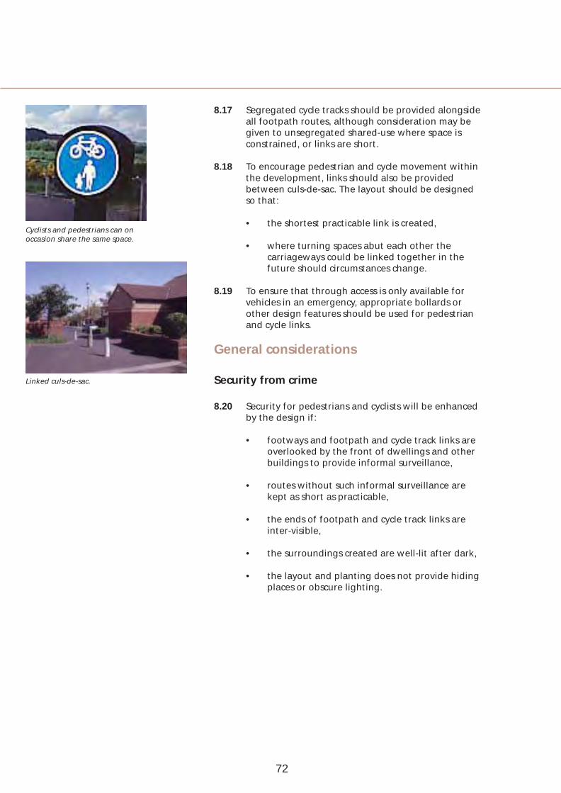
Cyclists and pedestrians can on occasion share the same space.
Linked culs-de-sac.
8.17 Segregated cycle tracks should be provided alongside all footpath routes, although consideration may be given to unsegregated shared-use where space is constrained, or links are short.
8.18 To encourage pedestrian and cycle movement within the development, links should also be provided between culs-de-sac. The layout should be designed so that:
• the shortest practicable link is created,
• where turning spaces abut each other the carriageways could be linked together in the future should circumstances change.
8.19 To ensure that through access is only available for vehicles in an emergency, appropriate bollards or other design features should be used for pedestrian and cycle links.
General considerations
Security from crime
8.20 Security for pedestrians and cyclists will be enhanced by the design if:
• footways and footpath and cycle track links are overlooked by the front of dwellings and other buildings to provide informal surveillance,
• routes without such informal surveillance are kept as short as practicable,
• the ends of footpath and cycle track links are inter-visible,
• the surroundings created are well-lit after dark,
• the layout and planting does not provide hiding places or obscure lighting.
72
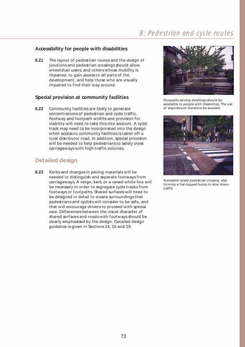
8: Pedestrian and cycle routes
Accessibility for people with disabilities
8.21 The layout of pedestrian routes and the design of junctions and pedestrian crossings should allow wheelchair users, and others whose mobility is impaired, to gain access to all parts of the development, and help those who are visually impaired to find their way around.
Special provision at community facilities
8.22 Community facilities are likely to generate concentrations of pedestrian and cycle traffic. Footway and footpath widths and provision for visibility will need to take this into account. A cycle track may need to be incorporated into the design when access to community facilities is taken off a local distributor road. In addition, special provision will be needed to help pedestrians to safely cross carriageways with high traffic volumes.
Detailed design
8.23 Kerbs and changes in paving materials will be needed to distinguish and separate footways from carriageways. A verge, kerb or a raised white line will be necessary in order to segregate cycle tracks from footways or footpaths. Shared surfaces will need to be designed in detail to create surroundings that pedestrians and cyclists will consider to be safe, and that will encourage drivers to proceed with special care. Differences between the visual character of shared surfaces and roads with footways should be clearly emphasised by the design. Detailed design guidance is given in Sections 14, 16 and 19.
Footpaths serving dwellings should be accessible to people with disabilities. The use of steps should therefore be avoided.
Accessible raised pedestrian crossing, also forming a flat-topped hump to slow down traffic.
73

9 Bus routes To achieve more sustainable travel patterns, a shift from the use of private cars to a greater use of public transport is desirable. This section sets out how developers can contribute to this objective through provision for access by buses.
Main objectives
9.01 To help reduce dependence on the car and promote greater use of buses, the design will need to ensure that:
• the layout contributes to the efficient movement of buses around the local area,
• convenient bus routes are created to serve the development,
• bus stops are within easy reach of all dwellings and serve any community buildings and common open spaces,
• where appropriate, priority for access is given to buses over other vehicular traffic.
74

9: Bus routes
Consultations
9.02 Developers should consult the bus operator, in conjunction with the Department and the Roads Service, at an early stage in the design process to find out whether a bus service is provided in, or planned for, the local area and to determine what facilities will be needed within the development site.
Bus route layout
9.03 Design requirements for bus routes are generally more space-consuming and demanding in other respects than for other kinds of roads. For this reason, bus routes can be a major determinant of the road layout and will need to be given a high priority in the design. Special care will, however, be needed to make sure that the visual character and safety of the development is not adversely affected by any special provision that has to be made for buses.
9.04 Greater flexibility will be possible in the requirements necessary for bus route provision where it is intended to use small buses, and the Department and the Roads Service will therefore wish to liaise with developers and the bus operator on this matter.
9.05 The design of the layout will need to provide a convenient route for use by buses and ensure that the catchment area for each bus stop is optimised.
9.06 When relevant, the road layout should be designed to take into account the possibility of extending the bus route into adjacent future developments.
9.07 Access roads incorporating speed restraint measures may, on occasion, have to accommodate buses when such provision is needed within the site. The lengths of any such roads that must serve as bus routes should therefore be kept to a minimum.
9.08 Appropriate measures may be required in the layout to provide priority for buses over other kinds of vehicles. The need for, and type of, such measures should be discussed with the Department and the Roads Service together with the bus operator.
Discussions with the bus operator will be necessary at an early stage in the design.
Special measures for buses may be needed in the layout.
75

Standard size bus.
Speed cushions are the prefered method of vertical displacement on bus routes.
Carriageways
9.09 The design requirements for bus routes will depend on the size and type of buses that are to be used on the route. The following requirements refer specifically to bus routes which will be served by standard size buses. Where it is intended to use small buses these requirements will generally be unnecessary. In such cases the advice of the Department and the Roads Service should be sought.
Carriageway widths
9.10 The minimum carriageway width of a local distributor road that will serve as a bus route is 6.7m where bus lay-bys are provided, and 7.3m wide when lay-bys are not provided. A minimum carriageway width of 6m will be required where access roads carry buses.
Speed restraints
9.11 On those occasions where buses need to be routed along access roads incorporating speed restraint, design measures involving changes in the horizontal alignment of carriageways are generally preferable to vertical displacements. Also, for operational efficiency and safety, it will be necessary to avoid creating too many closely spaced T-junctions or tight bends along such routes. For these reasons, it may be necessary to use vertical displacements in at least some places, and preference should be given to the use of speed cushions. Raised junctions and flat-topped humps will also be acceptable, but should be designed so that the raised table created can accommodate the full extent of the bus wheelbase.
9.12 Design requirements for speed restraints and other aspects of carriageway design are set out in Sections 16 and 18.
Lay-bys and turning facilities
9.13 Bus stop lay-bys should only be considered on local distributor roads and at bus termini. Where a lay-by is needed, the options of a parallel bay or shallow saw tooth bay are available. In larger developments special facilities for buses to turn, or a bus terminus, may need to be provided. Design details for lay-bys and termini are illustrated in Section 15.
9.14 On access roads, bus lay-bys should not be provided and bus stops should be at straight stretches of kerb.
76

9: Bus routes
Bus stops
9.15 Bus stops should be located where they are convenient to use and the safety of disembarking passengers, and road users, has been taken into account. Where bus stops on existing roads in the surrounding area are not conveniently located, developers should examine with the bus operator the scope for re-location of stops or the provision of additional facilities within the site.
9.16 Bus stops should be within easy reach of all dwellings. Around 100m should be the maximum walking distance for dwellings designed for the elderly or those whose mobility is impaired. The majority of other dwellings should be within around 200m. The maximum walking distance should be around 400m. Where sites are hilly these distances may need to be reduced.
9.17 Bus stops should be spaced between around 250m - 350m apart along the bus route. Bus stops should be well designed,
convenient and informative.
9.18 Bus stops will need to be located so that they are:
• close to junctions with side roads or footpaths,
• grouped with amenities such as a telephonekiosk or post box,
• adjacent to, or at least within around 50m of,community buildings and large common openspaces such as playing fields,
• free of obstructive parking and designed so thatbus drivers will find them convenient to use.
9.19 Bus stops should be provided with timetable and service information, shelter from wind and rain, seating and good street lighting or alternatively illumination in the shelter itself.
9.20 Trees should not obscure lines of sight for bus drivers toward intending passengers at bus stops or shelters.
9.21 Responsibility for the provision of necessary facilities on bus routes will rest with the developer. This matter should therefore be discussed at an early stage in the design process with the Department. Close liasion will also be necessary with the bus operator as it will ultimately be responsible for the maintenance of such facilities.
Well-designed bus shelters will add to the quality of the surroundings.
77

10 Routes for cars and service vehicles
Care will be required in the design of the layout and provision made for vehicular access to avoid the dominance of roads and traffic, and to provide high quality environments in which to live. This section sets out ways in which the design of the routes provided for cars and service vehicles can contribute to quality and sustainability.
Main objectives
10.01 The layout and detailed design of carriageways will need to ensure that:
• vehicle flows on access roads are minimised,
• non-access vehicular traffic finds local distributor roads more convenient to use than access roads,
• design measures restrain vehicle speeds on access roads,
• the access provided is safe to use,
• fire, ambulance and other emergency services are able to gain ready access.
78
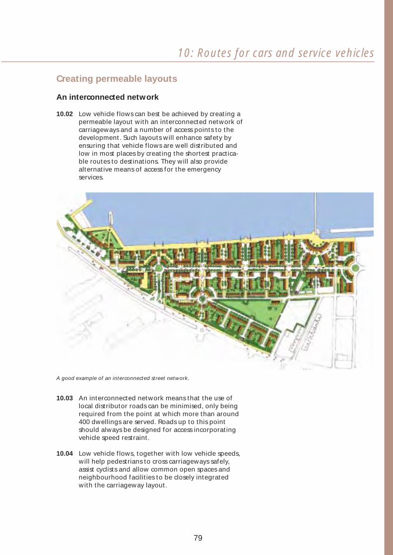
10: Routes for cars and service vehicles
Creating permeable layouts
An interconnected network
10.02 Low vehicle flows can best be achieved by creating a permeable layout with an interconnected network of carriageways and a number of access points to the development. Such layouts will enhance safety by ensuring that vehicle flows are well distributed and low in most places by creating the shortest practicable routes to destinations. They will also provide alternative means of access for the emergency services.
A good example of an interconnected street network.
10.03 An interconnected network means that the use of local distributor roads can be minimised, only being required from the point at which more than around 400 dwellings are served. Roads up to this point should always be designed for access incorporating vehicle speed restraint.
10.04 Low vehicle flows, together with low vehicle speeds, will help pedestrians to cross carriageways safely, assist cyclists and allow common open spaces and neighbourhood facilities to be closely integrated with the carriageway layout.
79

Deterring non-access vehicular traffic
A broken network
10.05 Though an unbroken network of roads with a number of points of access is preferable, it may be necessary to take special steps to deter or prevent non-access traffic from taking short cuts. This can often be done by making short cuts significantly more tortuous and time-consuming.
10.06 The two diagrams adjacent illustrate layouts with a different degree of deterrence to vehicles taking short cuts, while allowing residents and those providing delivery and collection services to go in a variety of directions and thereby help to keep travel distances to a minimum. Footpath and cycle links should be provided in these circumstances and special arrangements may be necessary to facilitate buses.
10.07 The design measures needed to restrain vehicle speeds may also be effective in discouraging non-access vehicular traffic from taking short cuts.
Small developments
10.08 Every effort should be made to create a permeable
Schematic layouts showing carriageway layout in designing small developments permeable streets, but with some or discrete parts of large developments. Whenever restrictions for vehicle access. practicable, short through routes or compact loops
should be used instead of culs-de-sac. Such loops and through routes would put to better use the land that would otherwise be occupied by the large turning spaces required at the heads of culs-de-sac. They will also facilitate the movement of larger vehicles and reduce the hazards that may be caused - especially for children - by vehicles having to reverse.
Culs-de-sac
10.09 The Department accepts that, in individual cases, there may be site constraints or other important reasons why the use of short culs-de-sac would be an acceptable design solution. They may be needed to discourage non-access vehicular traffic from taking short cuts across the site and also to help restrain vehicle speeds. Footpath and cycle links should be integrated into the design of culs-de-sac to facilitate pedestrian and cycle movement within the development.
. 10.10 Turning spaces, circles or loops should be provided at
the heads of culs-de-sac to avoid service vehicles having to reverse out of such roads. Turning circles and loops have the additional advantage of providing space to plant large trees.
80

10: Routes for cars and service vehicles
Restraining vehicle speeds
10.11 Restraining vehicle speeds through the introduction of traffic calming has proved to be effective in improving road safety. Research has also indicated that in accidents involving vehicles travelling at 20mph or lower, the risk of death or serious injury is greatly reduced. This is of particular importance in a residential environment. Accordingly the Department will generally wish to see all access roads within new development designed to a 20mph target maximum speed or lower. In such cases it may be possible to designate the area as a 20mph speed limit zone.
Compliance with regulations
10.12 General requirements for speed restraints are controlled by regulations made within the legislative framework. These, together with other published guidance such as Traffic Advisory Leaflets produced by the Department of the Environment, Transport and the Regions, provide helpful advice on the type and dimensions of a number of speed restraint measures, as well as information regarding signage and markings, illumination and materials used. The following paragraphs provide guidance on those measures acceptable for inclusion in new developments. The Department and the Roads Service should be consulted together at an early stage in the design process to discuss the application of speed restraint measures, in particular, the balance of measures proposed, their spacing, and any special signing requirements.
Restraint design
10.13 Wherever possible, vehicle speeds should be restrained and managed by the arrangement of buildings and spaces within the layout. Physical traffic calming measures, such as chicanes and road humps, should be regarded as backup measures where the layout alone does not produce low speeds.
20mph is the desirable target maximum speed in residential areas.
Speed restraint measures integrated with the design of a main street in Germany.
Use of a flat-topped hump as an integral part of housing design in the Netherlands.
Gate pillars at the entrance to this development, a narrow road and landscaping, all signal that speed should be slow.
81
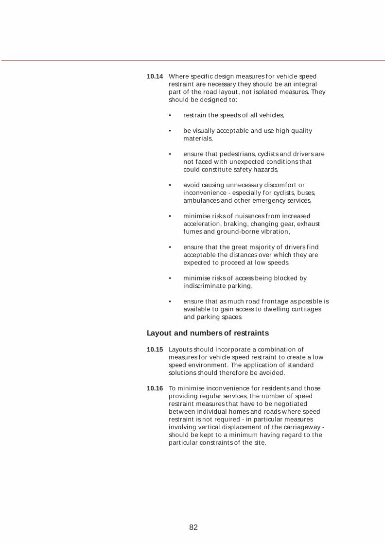
10.14 Where specific design measures for vehicle speed restraint are necessary they should be an integral part of the road layout, not isolated measures. They should be designed to:
• restrain the speeds of all vehicles,
• be visually acceptable and use high quality materials,
• ensure that pedestrians, cyclists and drivers are not faced with unexpected conditions that could constitute safety hazards,
• avoid causing unnecessary discomfort or inconvenience - especially for cyclists, buses, ambulances and other emergency services,
• minimise risks of nuisances from increased acceleration, braking, changing gear, exhaust fumes and ground-borne vibration,
• ensure that the great majority of drivers find acceptable the distances over which they are expected to proceed at low speeds,
• minimise risks of access being blocked by indiscriminate parking,
• ensure that as much road frontage as possible is available to gain access to dwelling curtilages and parking spaces.
Layout and numbers of restraints
10.15 Layouts should incorporate a combination of measures for vehicle speed restraint to create a low speed environment. The application of standard solutions should therefore be avoided.
10.16 To minimise inconvenience for residents and those providing regular services, the number of speed restraint measures that have to be negotiated between individual homes and roads where speed restraint is not required - in particular measures involving vertical displacement of the carriageway should be kept to a minimum having regard to the particular constraints of the site.
82
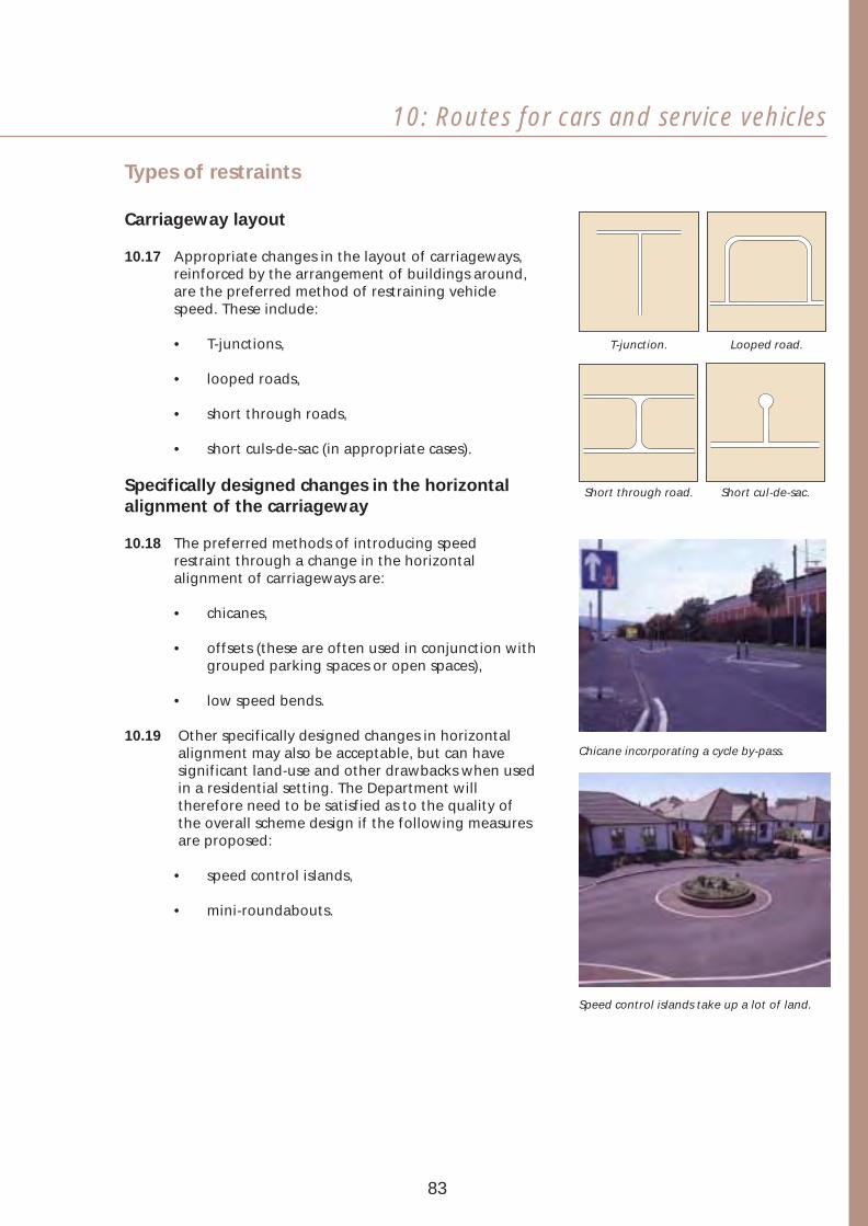
10: Routes for cars and service vehicles
Types of restraints
Carriageway layout
10.17 Appropriate changes in the layout of carriageways, reinforced by the arrangement of buildings around, are the preferred method of restraining vehicle speed. These include:
• T-junctions, T-junction. Looped road.
• looped roads,
• short through roads,
• short culs-de-sac (in appropriate cases).
Specifically designed changes in the horizontal Short through road. Short cul-de-sac. alignment of the carriageway
10.18 The preferred methods of introducing speed restraint through a change in the horizontal alignment of carriageways are:
• chicanes,
• offsets (these are often used in conjunction withgrouped parking spaces or open spaces),
• low speed bends.
10.19 Other specifically designed changes in horizontal alignment may also be acceptable, but can have significant land-use and other drawbacks when used in a residential setting. The Department will therefore need to be satisfied as to the quality of the overall scheme design if the following measures are proposed:
• speed control islands,
• mini-roundabouts.
Chicane incorporating a cycle by-pass.
Speed control islands take up a lot of land.
83

Footways
Raised junction
Carriageway
Ramp
Raised junctions.
Carriageway Footway
Footway
Raised to footway level
Parking on street
Vertical displacements of the carriageway
10.20 The Department recognises that it may be unreasonable or impractical to restrain vehicle speeds by using only changes in the layout of carriageways or specific changes in horizontal alignment. In these circumstances, it will be acceptable to use vertical displacements of the carriageway in the form of raised junctions, flat-topped road humps and speed cushions. Round-topped road humps will not, however, be acceptable in new developments.
Raised junctions
10.21 Raised junctions in the form of a speed table will need to extend across the entire junction including all the approaches. These measures may be used at T-junctions to restrain speeds along the priority road and at crossroads to restrain speeds in both directions. The use of raised junctions will not be acceptable at the entrances to the development.
10.22 The raised level should extend sufficiently to allow pedestrians to cross at, or near, uniform level, adjusting the footway where necessary. The level through the junction should also be maintained to such an extent so as not to interfere with the turning movements of cyclists and tall vehicles, including buses.
10.23 Connections to private driveways1 may be provided within the length of the raised junction but not from the ramps or the radii.
Flat-topped road humps
10.24 Flat-topped road humps may be used selectively along access roads in order to:
• interrupt what would otherwise be an excessively long stretch of carriageway,
• create a pedestrian crossing place where this is part of the overall planned pattern of pedestrian movement,
• emphasise a pedestrian crossing place where parking bays are located and footways are extended.
10.25 Connections to private driveways1 may be provided within the length of the flat top but not from the ramps.Flat-topped road humps.
1 In the interests of safety, connections to driveways will not be acceptable where a pedestrian crossing point is incorporated into the design.
84
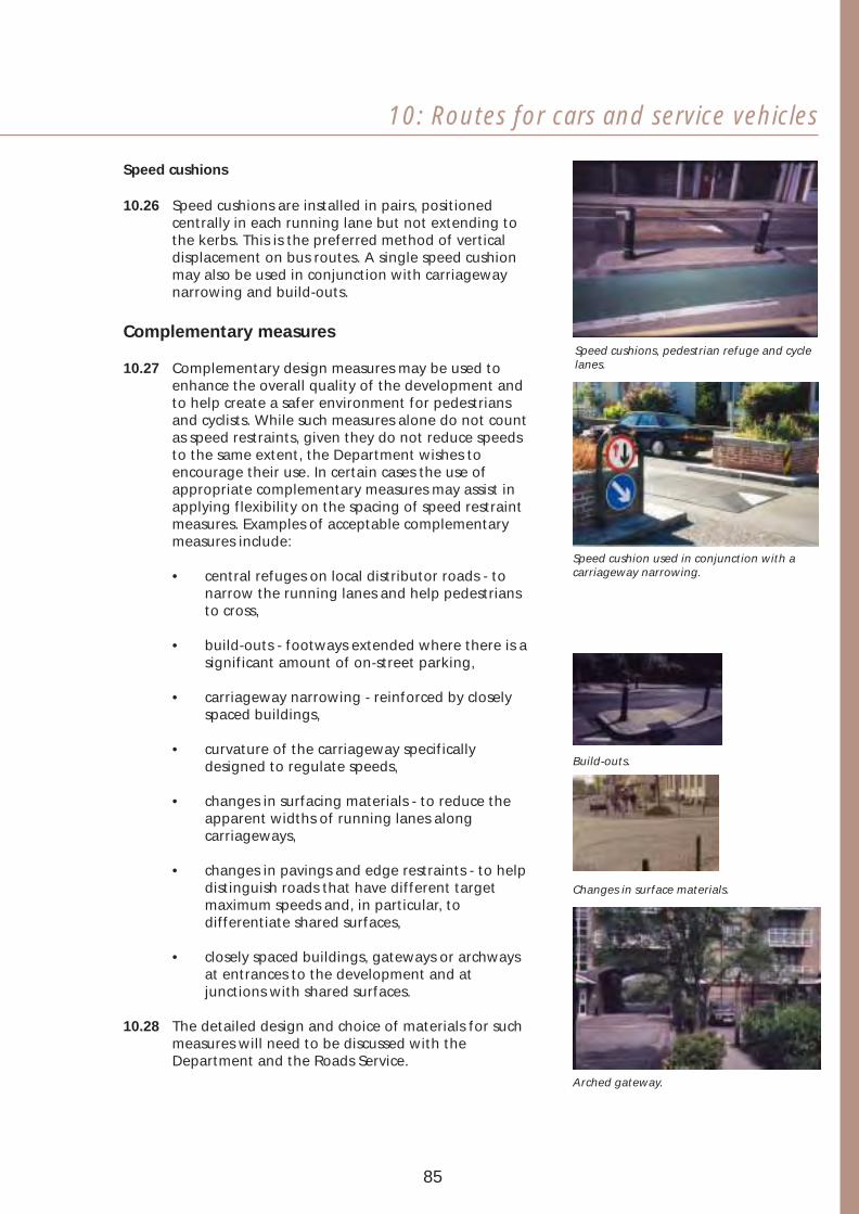
10: Routes for cars and service vehicles
Speed cushions
10.26 Speed cushions are installed in pairs, positioned centrally in each running lane but not extending to the kerbs. This is the preferred method of vertical displacement on bus routes. A single speed cushion may also be used in conjunction with carriageway narrowing and build-outs.
Complementary measures
10.27 Complementary design measures may be used to enhance the overall quality of the development and to help create a safer environment for pedestrians and cyclists. While such measures alone do not count as speed restraints, given they do not reduce speeds to the same extent, the Department wishes to encourage their use. In certain cases the use of appropriate complementary measures may assist in applying flexibility on the spacing of speed restraint measures. Examples of acceptable complementary measures include:
Speed cushions, pedestrian refuge and cycle lanes.
• central refuges on local distributor roads - tonarrow the running lanes and help pedestriansto cross,
Speed cushion used in conjunction with a carriageway narrowing.
• build-outs - footways extended where there is asignificant amount of on-street parking,
• carriageway narrowing - reinforced by closelyspaced buildings,
• curvature of the carriageway specifically designed to regulate speeds, Build-outs.
• changes in surfacing materials - to reduce theapparent widths of running lanes alongcarriageways,
• changes in pavings and edge restraints - to helpdistinguish roads that have different targetmaximum speeds and, in particular, todifferentiate shared surfaces,
Changes in surface materials.
• closely spaced buildings, gateways or archwaysat entrances to the development and atjunctions with shared surfaces.
10.28 The detailed design and choice of materials for such measures will need to be discussed with the Department and the Roads Service.
Arched gateway.
85

V
Other speed restraint measures
10.29 In addition to the measures outlined above, the Department may be prepared to consider the use of other design measures that will restrain vehicle speeds, where it can be demonstrated that they satisfy the overall objectives of quality development and road safety. These may involve either changes in the horizontal alignment of carriageways or vertical displacement measures or a combination of both.
10.30 Further information on speed restraint and complementary measures is set out in Section 18.
Spacing of restraints
10.31 Normal requirements for target maximum speeds and the spacing of restraint measures are summarised in Table 1 and should be read in conjunction with the paragraphs following.
Table 1 Target maximum speeds and spacing of restraints
Number of dwellings served by the stretch of road being considered
(around)
0-200 200-400 (Local distributor
road)
400
Target maximum speed (mph) 20(1) 20-30(2) 30
Restraints required (Yes/No) Y Y N
Maximum distance between restraints in metres (around)
60 60-100(3) none
(1) The target maximum speed should be well below 20mph along shared surfaces and outside schools, or elsewhere in the layout where children may be especially at risk. The maximum distance between restraints in such cases should therefore be around 40m.
(2) The Department wishes to promote road safety and this would be better achieved with a 20mph target maximum speed.
(3) The actual distance to be used is dependent on the target maximum speed.
86
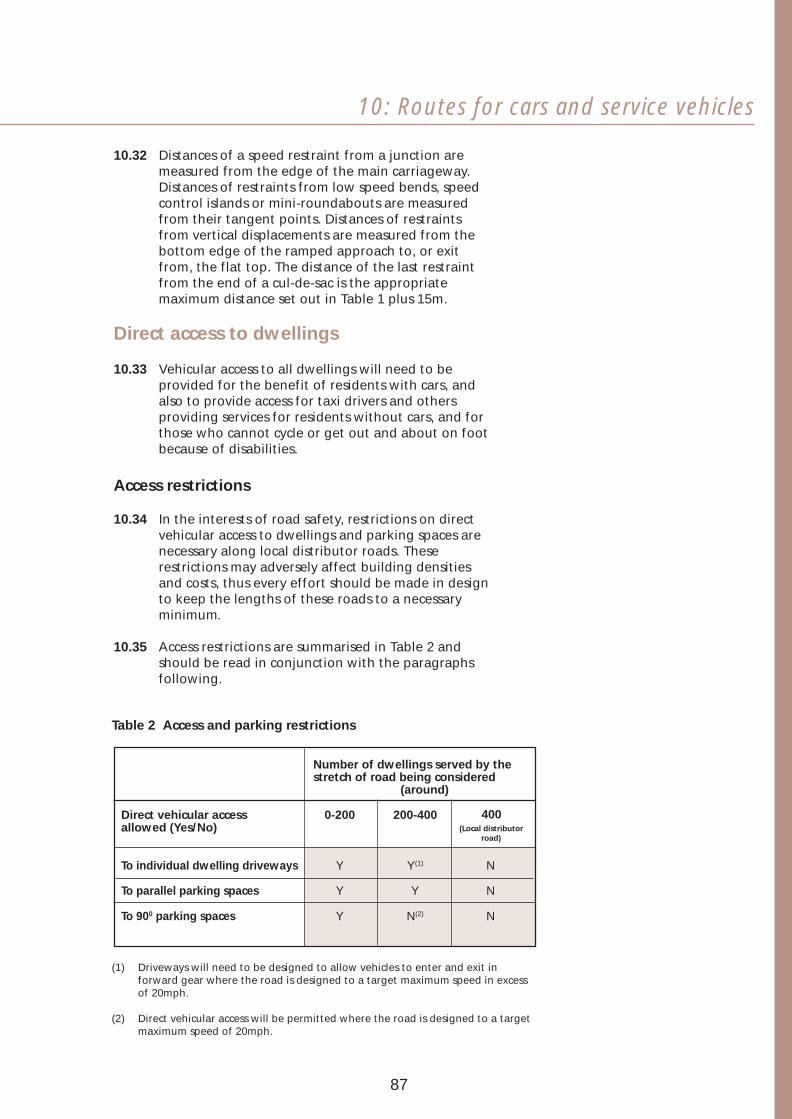
V
10: Routes for cars and service vehicles
10.32 Distances of a speed restraint from a junction are measured from the edge of the main carriageway. Distances of restraints from low speed bends, speed control islands or mini-roundabouts are measured from their tangent points. Distances of restraints from vertical displacements are measured from the bottom edge of the ramped approach to, or exit from, the flat top. The distance of the last restraint from the end of a cul-de-sac is the appropriate maximum distance set out in Table 1 plus 15m.
Direct access to dwellings
10.33 Vehicular access to all dwellings will need to be provided for the benefit of residents with cars, and also to provide access for taxi drivers and others providing services for residents without cars, and for those who cannot cycle or get out and about on foot because of disabilities.
Access restrictions
10.34 In the interests of road safety, restrictions on direct vehicular access to dwellings and parking spaces are necessary along local distributor roads. These restrictions may adversely affect building densities and costs, thus every effort should be made in design to keep the lengths of these roads to a necessary minimum.
10.35 Access restrictions are summarised in Table 2 and should be read in conjunction with the paragraphs following.
Table 2 Access and parking restrictions
Number of dwellings served by the stretch of road being considered
(around)
Direct vehicular access allowed (Yes/No)
0-200 200-400 (Local distributor
road)
400
To individual dwelling driveways Y Y(1) N
To parallel parking spaces Y Y N
To 900 parking spaces Y N(2) N
(1) Driveways will need to be designed to allow vehicles to enter and exit in forward gear where the road is designed to a target maximum speed in excess of 20mph.
(2) Direct vehicular access will be permitted where the road is designed to a target maximum speed of 20mph.
87

Access along distributor roads
10.36 While direct vehicular access to individual dwellings or parking spaces will not be allowed from local distributor roads, dwellings should always front onto these roads in order to help make the route visually attractive and provide informal surveillance. The following paragraphs describe four examples of acceptable access arrangements.
Looped access road
Houses
10.37 A looped access road taken off, and running parallel to, the distributor road to serve single-sided development of no more than around 20 dwellings in total. The junctions should be spaced not less than around 45m apart from adjacent junctions and 25m for opposite. The distance between the junctions of the looped access road itself should also not be less than around 45m.
Shared driveway
10.38 A shared driveway taken off the distributor road to Looped access road. serve single-sided development of between 2 and 5
dwellings fronting onto the distributor road. Access to a shared driveway, similar to the looped access road arrangement described above, should be spaced not less than around 45m from an adjacent junction and 25m for opposite. Turning arrangements should be such that vehicles would not have to reverse out onto the distributor road.
Houses
Shared driveway.
10.39 To prevent a proliferation of such accesses onto the distributor road, the use and number of shared driveways should be kept to a minimum. Accordingly, this access arrangement is generally only considered suitable to accommodate frontage development where there is only a short length of distributor road between junctions. In circumstances where frontage development in excess of 10 dwellings has to be accommodated, a looped access road or other appropriate access arrangements should be used.
HousesHouses
HousesHouses
Parallel access road
10.40 An access road within the development extended to run in parallel with the distributor road to serve single-sided development with dwellings fronting onto the distribution road.
10.41 For all three of the above arrangements there should be sufficient provision for parking within house curtilages and on the carriageway of the access road or shared driveway to make it unnecessary for drivers to park on the distributor road.
Parallel access road.
88
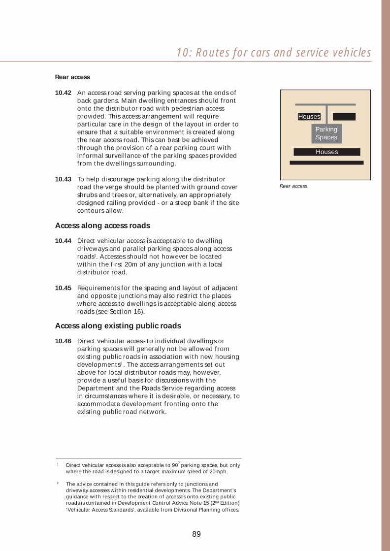
10: Routes for cars and service vehicles
Rear access
10.42 An access road serving parking spaces at the ends of back gardens. Main dwelling entrances should front onto the distributor road with pedestrian access provided. This access arrangement will require particular care in the design of the layout in order to ensure that a suitable environment is created along the rear access road. This can best be achieved through the provision of a rear parking court with informal surveillance of the parking spaces provided from the dwellings surrounding.
10.43 To help discourage parking along the distributor road the verge should be planted with ground cover Rear access.
shrubs and trees or, alternatively, an appropriately designed railing provided - or a steep bank if the site contours allow.
Houses Houses
Parking Spaces
Houses
Access along access roads
10.44 Direct vehicular access is acceptable to dwelling driveways and parallel parking spaces along access roads1. Accesses should not however be located within the first 20m of any junction with a local distributor road.
10.45 Requirements for the spacing and layout of adjacent and opposite junctions may also restrict the places where access to dwellings is acceptable along access roads (see Section 16).
Access along existing public roads
10.46 Direct vehicular access to individual dwellings or parking spaces will generally not be allowed from existing public roads in association with new housing developments2 . The access arrangements set out above for local distributor roads may, however, provide a useful basis for discussions with the Department and the Roads Service regarding access in circumstances where it is desirable, or necessary, to accommodate development fronting onto the existing public road network.
01 Direct vehicular access is also acceptable to 90 parking spaces, but only where the road is designed to a target maximum speed of 20mph.
2 The advice contained in this guide refers only to junctions and driveway accesses within residential developments. The Department’s guidance with respect to the creation of accesses onto existing public roads is contained in Development Control Advice Note 15 (2nd Edition) ‘Vehicular Access Standards’, available from Divisional Planning offices.
89

Access to community buildings
10.47 Most community buildings will require provision for regular access by large service vehicles. In addition, such buildings can generate considerable demands for parking spaces. For these reasons, special steps will need to be taken to minimise hazards and nuisances. The provision normally required will include:
• approach roads served from either a local distributor road or an access road designed to take large service vehicles,
• separate access via a service road defined for this purpose to the rear of premises such as shops,
• picking-up and setting-down spaces close to the main entrances of the buildings.
10.48 Buses will normally need to be able to park within the grounds of schools and provision for turning should be made to enable them to exit in forward gear. Bus movements and parking should be segregated from those of parents’ cars.
10.49 In the interests of safety, verges should be provided to separate footways from carriageways where the main entrances to community buildings are located.
Picking-up and setting-down spaces in the grounds of a school.
90

10: Routes for cars and service vehicles
91

11 Parking provision
Parking can have a considerable impact on the quality of the residential environment, and needs careful planning and design in order to save land, preserve visual character and avoid excessive provision. This section describes the contributions to quality and sustainability that can be made by appropriate provision for parking.
Main objectives
11.01 The main objectives in making provision for parking are to:
• enhance the visual character of the development, by ensuring that cars and bicycles are an unobtrusive part of the scene through the appropriate location, layout and detailed design of the parking spaces,
• reduce the use of cars and conserve land by providing no more than the minimum number of vehicle parking spaces required to meet future demands,
• encourage cycling, by providing sufficient numbers of bicycle parking spaces to meet future demands,
• reduce risks of theft and vandalism, by providing informal surveillance of parking spaces,
• reduce the hazards that can be caused by indiscriminate parking, by providing accessible, safe and convenient off-street parking spaces.
92

11: Parking provision
Visual character
11.02 To help make parking provision visually unobtrusive the layout of the development as a whole should be designed to:
• make building plots wide enough and deep enough to plant trees and shrubs to soften the visual impact of in-curtilage parking provision located in front of the building line,
• plant trees and shrubs to break up and soften the visual impact of on-street parking and cars parked in grouped parking areas,
• use design features such as changes of ground level and low walls to reduce the extent to which large groups of parked cars and bicycles can be seen from a distance,
• use a mixture of paving materials to break up the visual impact of hard surfaces in grouped parking areas.
Numbers of spaces required
For dwellings
Bicycle spaces
11.03 Sufficient space should be provided for bicycle parking within dwellings, garages or outside. Communal bicycle stands should normally be provided in association with apartment developments.
Vehicle spaces
11.04 Developments will normally need to provide the levels of parking provision set out in Section 20. Lesser provision may be acceptable in inner urban locations and other high-density areas. In special circumstances, in some inner urban locations, ‘car-free’ developments may be considered appropriate - where it can be demonstrated that households will not own a car or will keep it elsewhere.
For local neighbourhood facilities
11.05 The Department’s Divisional Planning Offices should be consulted about requirements for bicycle and vehicle-parking spaces to serve local neighbourhood facilities.
Good planting and well laid out parking in low-density housing.
Carport designed to integrate with house types.
In-curtilage parking partly screened by fences and landscaping.
Front gardens with railings designed to incorporate parking.
Provision for cycle parking.
93
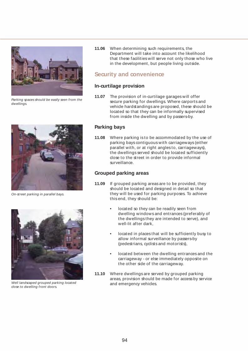
Parking spaces should be easily seen from the dwellings.
On-street parking in parallel bays.
Well landscaped grouped parking located close to dwelling front doors.
11.06 When determining such requirements, the Department will take into account the likelihood that these facilities will serve not only those who live in the development, but people living outside.
Security and convenience
In-curtilage provision
11.07 The provision of in-curtilage garages will offer secure parking for dwellings. Where carports and vehicle hardstandings are proposed, these should be located so that they can be informally supervised from inside the dwelling and by passers-by.
Parking bays
11.08 Where parking is to be accommodated by the use of parking bays contiguous with carriageways (either parallel with, or at right angles to, carriageways), the dwellings served should be located sufficiently close to the street in order to provide informal surveillance.
Grouped parking areas
11.09 If grouped parking areas are to be provided, they should be located and designed in detail so that they will be used for parking purposes. To achieve this end, they should be:
• located so they can be readily seen from dwelling windows and entrances (preferably of the dwellings they are intended to serve), and well-lit after dark,
• located in places that will be sufficiently busy to allow informal surveillance by passers-by (pedestrians, cyclists and motorists),
• located between the dwelling entrances and the carriageway - or else immediately opposite on the other side of the carriageway.
11.10 Where dwellings are served by grouped parking areas, provision should be made for access by service and emergency vehicles.
94
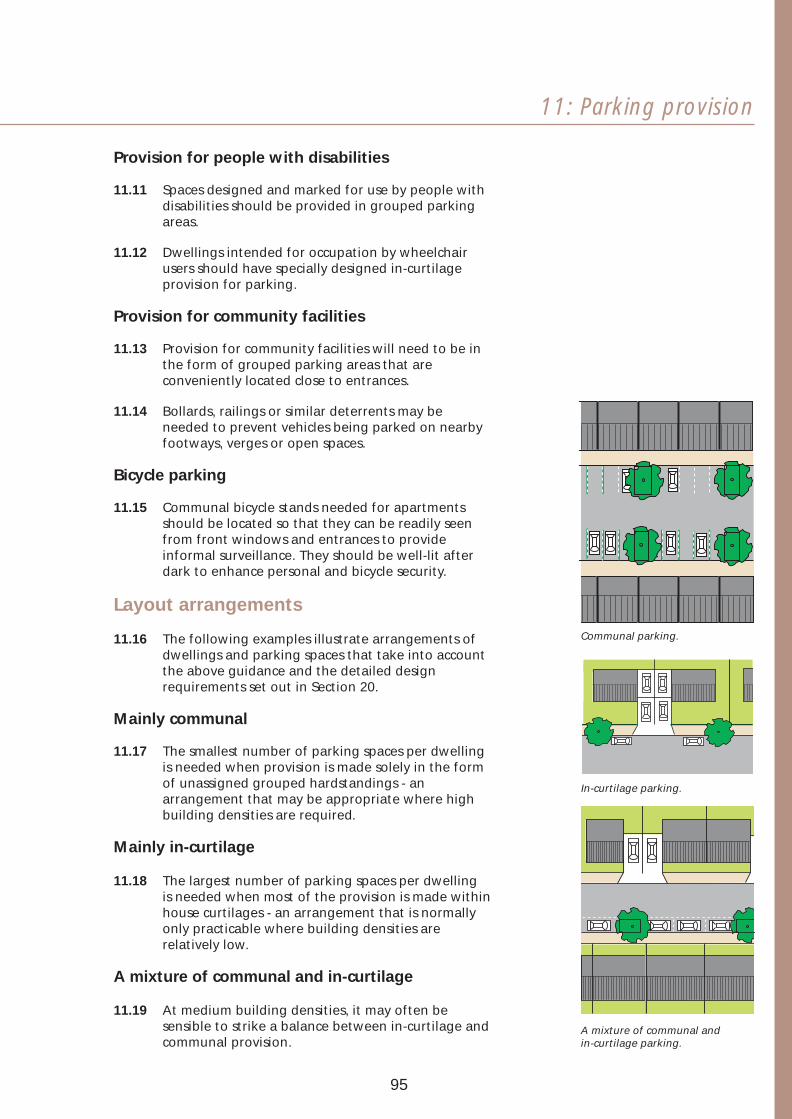
11: Parking provision
Provision for people with disabilities
11.11 Spaces designed and marked for use by people with disabilities should be provided in grouped parking areas.
11.12 Dwellings intended for occupation by wheelchair users should have specially designed in-curtilage provision for parking.
Provision for community facilities
11.13 Provision for community facilities will need to be in the form of grouped parking areas that are conveniently located close to entrances.
11.14 Bollards, railings or similar deterrents may be needed to prevent vehicles being parked on nearby footways, verges or open spaces.
Bicycle parking
11.15 Communal bicycle stands needed for apartments should be located so that they can be readily seen from front windows and entrances to provide informal surveillance. They should be well-lit after dark to enhance personal and bicycle security.
Layout arrangements
11.16 The following examples illustrate arrangements of dwellings and parking spaces that take into account the above guidance and the detailed design requirements set out in Section 20.
Mainly communal
11.17 The smallest number of parking spaces per dwelling is needed when provision is made solely in the form of unassigned grouped hardstandings - an arrangement that may be appropriate where high building densities are required.
Mainly in-curtilage
11.18 The largest number of parking spaces per dwelling is needed when most of the provision is made within house curtilages - an arrangement that is normally only practicable where building densities are relatively low.
A mixture of communal and in-curtilage
11.19 At medium building densities, it may often be sensible to strike a balance between in-curtilage and communal provision.
Communal parking.
In-curtilage parking.
A mixture of communal and in-curtilage parking.
95

Rear access
11.20 Garages and hardstandings located at the end of back gardens are often unpopular and underused because of fears about security. However, such arrangements may be inescapable when the aim is to create high quality traditional street scenes at the fronts of the houses (i.e. no provision is made for parking either in-curtilage or along the street). The security drawbacks of these arrangements can be mitigated if other dwellings are located at the rear and through routes are created to provide informal surveillance by passers-by. Particular care will be required in the design of such layouts in order to ensure that a high quality environment is created.
Rear access parking designed to be overlooked by some houses. The use of these parking courts means that traditional streets fronting directly onto footways can be designed.
96

11: Parking provision
97

12 Provision for services
The provision of services needs careful consideration in the design. The overall quality of a development can be affected by the provisions made for underground services, for lighting and the design and selection of street furniture.
Main objectives
12.01 The design of footways, verges, footpaths, cycle tracks and carriageways will need to ensure that the requirements of statutory undertakers and other service providers can be met - in particular to provide:
• suitable routes for water, electricity, gas, telecommunications and sewers,
• street lighting that will be economical to install and maintain,
• adequate space for above-ground equipment such as street lighting columns, mini pillars, telephone kiosks, sub-stations and salt boxes (taking into account the need to avoid any inconvenience or obstruction for cyclists and pedestrians - especially wheelchair users),
• adequate access for operational and maintenance purposes.
98

12: Provisions for services
Location of services underground
12.02 Routes for statutory and other services will need to be located in places that will be adopted as part of the public road network for future maintenance by the Roads Service.
12.03 Statutory undertakers have specific rights to lay apparatus in public roads, and developers should cater for the space requirements of these services in roads or verges in a manner acceptable to the Department and the Roads Service.
12.04 It is preferable for services to be laid in footways or verges rather than carriageways in order to minimise installation and repair costs, and disruption. Manhole covers should, where possible, also be located off the carriageway. If no other route is possible, then services and manhole covers may be sited in the carriageway, for example, routes for sewers or services to be provided in association with the development of housing squares and mews courts.
12.05 Where a public road or verge does not offer sufficient space for a statutory undertaker’s needs, then the developer must provide service routes with secure easements. The developer will be responsible for agreeing such easements with the statutory undertakers concerned.
12.06 Where routes for services only follow one side of a road developers will be reponsible for providing cross carriageway ducts in positions required by the statutory undertakers, and to mark temporarily the location of ducts for ease of access during construction.
Protection
12.07 Services will need to be ducted when located beneath the carriageway.
12.08 Where routes for services underground are to be provided in close proximity to verges where tree planting is proposed, the services underground will need to be protected by ducting or other means, and care taken in the selection of trees or shrubs.
99

Adopted but privately maintained verges
12.09 In the past along shared surface roads, where services have been located in adopted, but privately maintained, verges within front gardens (commonly referred to as ‘service strips’), it has often been impossible to protect the services from residents’ planting and built features such as walls and rockeries. In addition, residents have often inadequately maintained the verges, while the means used to demarcate them have been visually confusing and unpleasant.
12.10 In future, the Department will only accept shared surface developments that include services located beneath verges in front gardens, where the building density is no more than around 13 houses per hectare and no more than around 25 dwellings are proposed. In these circumstances, the verges will be adopted if:
• their location is indicated by markers such as setts at private driveways or at footpath or cycle track crossings,
• the status of the verges is made clear to purchasers in the conveyancing of the dwelling to make them aware that:
- the verges form part of the public road and that they should not build walls or fences or plant trees or shrubs thereon,
- service providers may need to excavate their services,
- where an electricity cable is installed, it could be a potential hazard to occupants who dig indiscriminately over the verges.
Co-ordination
12.11 The design of the layout must reconcile the requirements of the Department, the Roads Service and service providers, always bearing in mind that the overall objective of this guide is to create attractive residential environments.
12.12 The layout of services should be co-ordinated wherever possible. The joint trench principle is the ideal, but may often not be practicable. Care should always be taken, however to ensure that services do not conflict.
100

12: Provisions for services
Telecomms
Water
Gas
Cable TV
Elec hv
Elec lv
Elec lv All pos'nOutside stop valve
Lamp standard
Boundary
‘Typical’ disposition of services underground - the actual positions may vary according to local conditions. Also, there may be more than one LV or HV cable located under the footway.
12.13 Developers must provide the service providers with their proposals at the earliest possible stage, and designers must consider services as a basic design element.
12.14 Each statutory undertaker will need copies of plans, sections, drainage and sewerage details, including particulars of any underground structures or apparatus. These plans should indicate proposed start and finish dates of construction phases.
12.15 Agreement between the developer and service providers should be reached on essential aspects of servicing, including:
• programming the cut-off of services from anyexisting premises to be demolished,
• protection and diversion of existing services,
• access to, siting and connection of sub-stations,governors, etc.,
• wayleaves and easements,
• service layouts, particularly the construction andsiting of carriageway crossings and ducts,
• provision of services when routes from supplypoints cross undeveloped land,
• termination points in dwellings, entry detailsand meter reading facilities.
101

Quality lighting columns and wall mounted fittings can enhance the residential environment.
Lighting
12.16 A good quality lighting scheme should be planned as an integral part of the road, cycle track and footpath layout. The scheme should be designed to:
• provide adequate space for above-ground equipment such as street lighting columns and mini-pillars,
• ensure safe movement after dark - especially to minimise the risk of accidents by allowing pedestrians, cyclists and drivers to see each other and to identify potential hazards in the layout,
• reduce opportunities for crime - the careful location of lighting can help avoid creating shadows in places where pedestrians would otherwise be vulnerable,
• make it easier for strangers to find their way around.
12.17 Lighting columns and fittings make a major impact on the appearance of the development - both during the daytime and after dark - and should be carefully selected with this in mind.
12.18 Lighting columns and wall-mounted and other fittings should be acceptable to the Roads Service as it will ultimately assume responsibility for the lighting. In particular, the fittings should be:
• durable,
• resistant to damage from vandalism,
• easy to maintain,
• located to minimise inconvenience for residents,
• located to minimise risks of damage to equipment by vehicles.
Emergency services
12.19 The fire service and ambulance service should be consulted about their access requirements.
102

12: Provisions for services
Refuse collection
12.20 Consideration should be given to access requirements for refuse collection. Permeable layouts will facilitate ease of movement by refuse vehicles and direct vehicular access to the fronts of houses will allow refuse to be collected from bin stores. Refuse stores for apartments and maisonettes should be located to allow bins to be wheeled out to the kerb. The maximum carry distance will normally be around 25m.
Post boxes
12.21 The Post Office should be consulted about its requirements. Where practicable, post boxes should be built into walls rather than being free standing.
Telephone call boxes
12.22 A large development will justify the provision of one or more telephone call boxes. These should be located at nodal points in the layout where they will be readily visible.
Aerials and satellite dishes
12.23 Provision should be made for cable TV to serve all the dwellings in those areas where such a service is available. Otherwise covenants should normally require residents to locate aerials in lofts and satellite dishes away from the fronts of houses and roofs. Apartments should have a communal aerial and satellite dish wired to each dwelling if cable TV is not available.
Street nameplates and dwelling numbering
12.24 The local district council should be consulted about their requirements for street naming and dwelling numbering. Street names should preferably be fixed to walls and buildings. Dwelling numbers should be clearly visible from carriageways (both during the day and after dark). On culs-de-sac the appropriate sign should be incorporated into the street nameplate to indicate this.
An old post box built into a wall - good modern design should be chosen to be similarly sympathetic to the surroundings.
An attractive and well-lit house number.
103

104

Creating Places
Part 3
Detailed design requirements

13 Planting Specialist advice
13.01 Developers should seek specialist advice from a landscape architect and an arboriculturist regarding the management of the site at building stage – matters such as: the erection of protective fencing; preparing the ground for new planting; installing new trees and shrubs and repairing any damage to existing or new planting that occurs during building.
Retaining existing vegetation
13.02 The continued health of the vegetation to be retained will depend on good working practices during the construction works and on the continued long-term management after works have been completed. Top-soil should be removed and retained.
13.03 Prior to any building works commencing, developers will need to provide appropriate protective fencing for all trees to be retained. The area to be fenced will need to be of sufficient size to ensure that no damage is likely to the root system or drainage of the trees to be retained. In all cases protective fencing should encompass at least the area equivalent to the crown spread, or half the height of the trees, whichever is the greater. Care should be taken to ensure that within the area fenced:
• there is no stockpiling of building materials or surplus soil,
• there is no trafficking over or parking,
• no works of excavation, or raising or lowering of soil levels occurs,
• no fires are lit.
13.04 Branches should not be carelessly lopped off, roots amputated, nor trees used as an anchor for winching purposes. The possibility that damage to tree roots could render existing trees unstable should be taken into account when determining the location of buildings and external works, such as retaining walls and carriageways.
106

13: Planting
New planting
13.05 All new trees, shrubs and other plant material should be from a reputable source and of a high specification.
13.06 New trees should have a well-developed head with a clear strong leader, where applicable, and a well developed and properly prepared fibrous root system. Specimen trees should generally be at least heavy standard in size and extra heavy standard in size along a street or road. Semi-mature trees may also be required in appropriate locations and feathered trees and whips used in structure / boundary planting.
13.07 Good working practices should be followed at all times including:
• digging a tree pit large enough to allow the roots to be comfortably spread out,
• thoroughly loosening the soil at the bottom of the planting pit,
• using good quality top soils, additives and mulches,
• firming the roots and staking the tree using adequately sized stakes and ties.
13.08 All new planting operations should be carried out in accordance with British standard 4428:1989 ‘Code of Practice for General Landscape Operations’. Where trees are to be planted along streets or roads, care must be taken to ensure that there is adequate space for drainage and that the tree can be fed and watered as necessary.
13.09 Planting intended to provide shelter from noise or wind - or to integrate the development into the surrounding landscape - should, whenever practicable, be installed well in advance of the development taking place. Elsewhere within the layout planting may be phased as the development progresses.
107
Minimising maintenance
13.10 Care should be taken to select trees and shrubs that retain their natural character with only moderate maintenance - especially when planted alongside carriageways - particularly bus routes. The ideal is no pruning, but it may become necessary to control shape to suit the environment, to prevent defective growth or to improve a tree shape when it has been damaged. Pruning can also prevent trees from obscuring light, mask some feature or allow clear routes for traffic. Qualified arboriculturists should do the pruning in order to avoid ill treatment and ugly mutilation.
Design to minimise damage to trees
13.11 Special care in design is needed to minimise risks of damage to young trees and paving from vandalism and vehicles, and to ensure that wear, which is inevitable, is an unobtrusive and acceptable part of the overall scene. Tree guards will normally be required to protect trees when they are becoming established and, later, to prevent damage from vehicles and mowers.
13.12 Risks of damage by over-running vehicles will mainly be reduced by making adequate provision for off-street and on-street parking, and by ensuring that carriageways are wide enough to allow vehicles to pass each other. The appropriate use of bollards and high kerbs can also help prevent damage to trees by vehicles over-running.
Potential hazards
13.13 The choice of tree species should be carefully considered to prevent future problems arising. In particular:
• trees alongside carriageways should be selected and located to ensure that they will not need to be mutilated in order to allow for the passage of buses and other tall vehicles,
• trees in parking areas and along footways must be able to tolerate hostile growing conditions, and should be selected to ensure that droppings do not cause damage to paint on cars parked beneath or cause pavements to be slippery. Special allowance must also be made for the trees to get enough water and trunks should be protected from accidental damage,
108
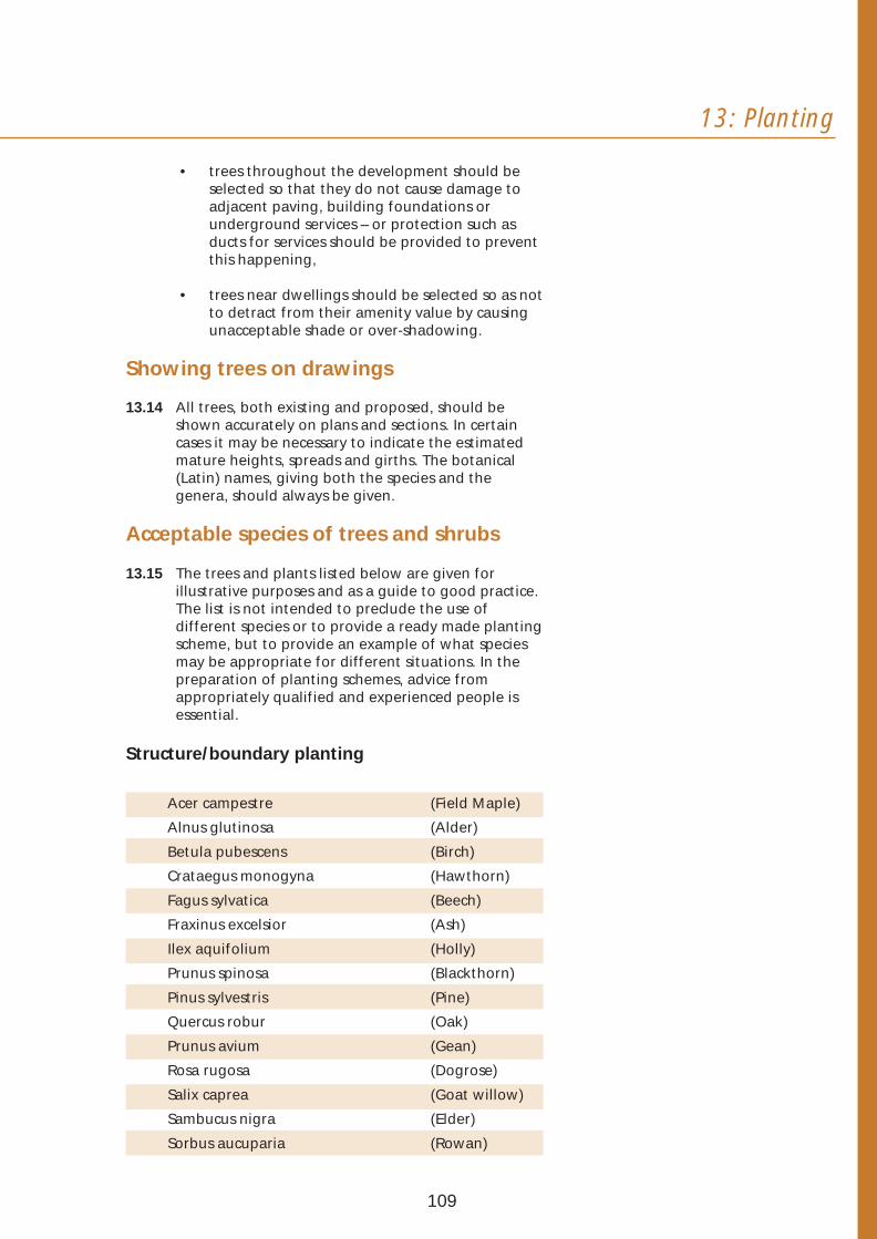
13: Planting
• trees throughout the development should be selected so that they do not cause damage to adjacent paving, building foundations or underground services – or protection such as ducts for services should be provided to prevent this happening,
• trees near dwellings should be selected so as not to detract from their amenity value by causing unacceptable shade or over-shadowing.
Showing trees on drawings
13.14 All trees, both existing and proposed, should be shown accurately on plans and sections. In certain cases it may be necessary to indicate the estimated mature heights, spreads and girths. The botanical (Latin) names, giving both the species and the genera, should always be given.
Acceptable species of trees and shrubs
13.15 The trees and plants listed below are given for illustrative purposes and as a guide to good practice. The list is not intended to preclude the use of different species or to provide a ready made planting scheme, but to provide an example of what species may be appropriate for different situations. In the preparation of planting schemes, advice from appropriately qualified and experienced people is essential.
Structure/boundary planting
Acer campestre (Field Maple)
Alnus glutinosa (Alder)
Betula pubescens (Birch)
Crataegus monogyna (Hawthorn)
Fagus sylvatica (Beech)
Fraxinus excelsior (Ash)
Ilex aquifolium (Holly)
Prunus spinosa (Blackthorn)
Pinus sylvestris (Pine)
Quercus robur (Oak)
Prunus avium (Gean)
Rosa rugosa (Dogrose)
Salix caprea (Goat willow)
Sambucus nigra (Elder)
Sorbus aucuparia (Rowan)
109
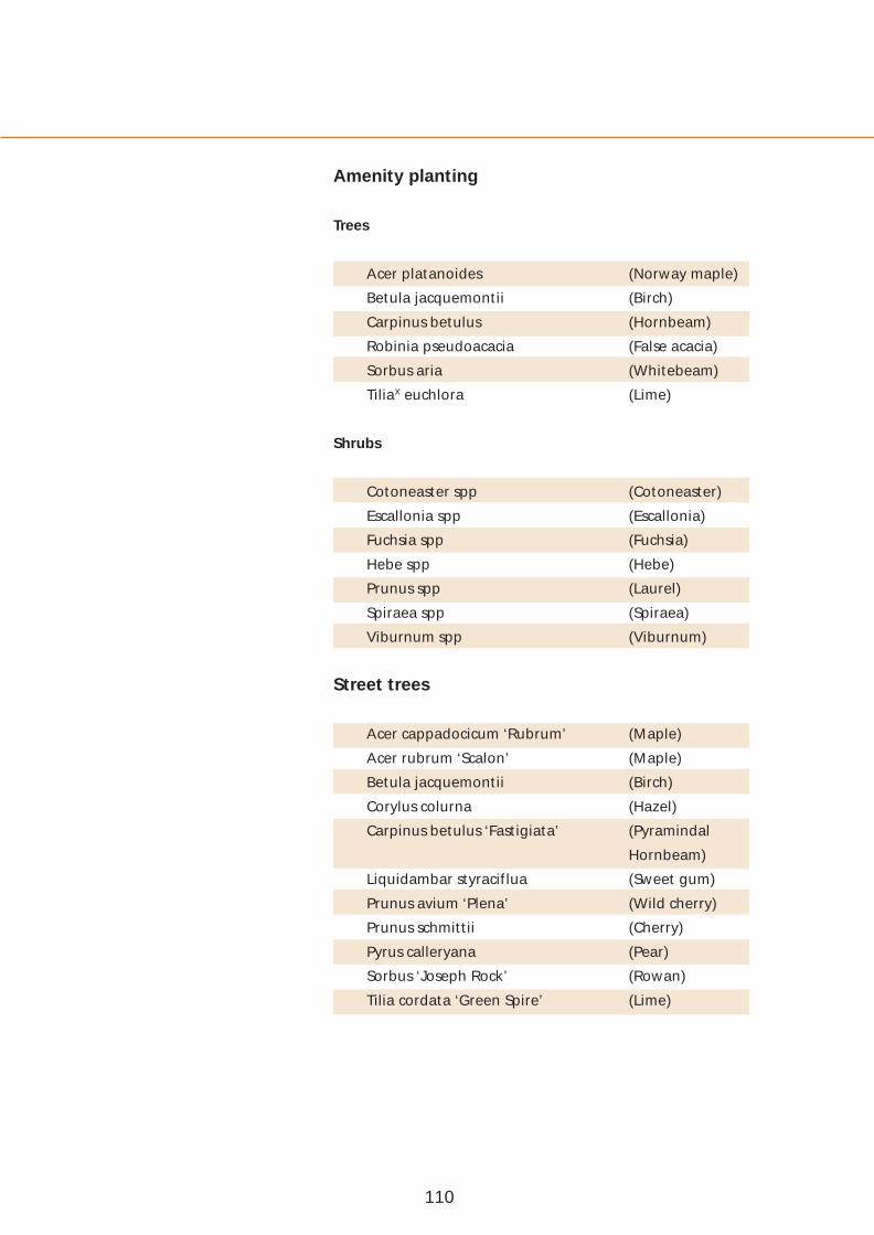
Amenity planting
Trees
Acer platanoides (Norway maple)
Betula jacquemontii (Birch)
Carpinus betulus (Hornbeam)
Robinia pseudoacacia (False acacia)
Sorbus aria (Whitebeam)
TiliaX euchlora (Lime)
Shrubs
Cotoneaster spp (Cotoneaster)
Escallonia spp (Escallonia)
Fuchsia spp (Fuchsia)
Hebe spp (Hebe)
Prunus spp (Laurel)
Spiraea spp (Spiraea)
Viburnum spp (Viburnum)
Street trees
Acer cappadocicum ‘Rubrum’ (Maple)
Acer rubrum ‘Scalon’ (Maple)
Betula jacquemontii (Birch)
Corylus colurna (Hazel)
Carpinus betulus ‘Fastigiata’ (Pyramindal
Hornbeam)
Liquidambar styraciflua (Sweet gum)
Prunus avium ‘Plena’ (Wild cherry)
Prunus schmittii (Cherry)
Pyrus calleryana (Pear)
Sorbus ‘Joseph Rock’ (Rowan)
Tilia cordata ‘Green Spire’ (Lime)
110

13: Planting
Garden trees and hedgerow planting
Trees
Acer plananoides ‘Drummondii’ (Maple)
Alnus glutinosa (Alder)
Betula pendula (Silver birch)
Crataegus oxyacantha ‘Pauls Scarlet’ (Hawthorn)
Malus ‘John Downie’ (Apple)
Prunus ‘Amanogawa’ (Cherry)
Sorbus aucuparia (Rowan)
Hedges
Carpinus betulus (Common
Hornbeam)
Escallonia macrantha (Escallonia)
Fagus sylvatica (Beech)
Griselinia littoralis (Griselinia)
Ligustrum ovalifolium (Privet)
Crataegus monogyna (Common
Howthorn)
Liex aquisolium (Common Holly)
Specimen trees
A number of trees, both coniferous and deciduous may be suitable. Consideration should be given to the location and conditions in making the final choice.
111

14 Footways, verges, footpaths and cycle tracks
750mm
1350mm
1250mm
1000mm
900mm
1800mm
Unobstructed widths for various types of pedestrian movement.
Footways
14.01 Widths: At least 2m. This will generally accommodate visibility splays, most services underground and allow wheelchair users to pass others using the footway. A greater footway width will, however, be required in the following circumstances:
• an additional 800mm (preferably in a different paving material) where vehicles park at right angles to the footway,
• at least 3m where pedestrians congregate, for example, outside shops, schools and community buildings and at bus stops,
• at least an additional 600mm to accommodate the planting of trees within the paved footway surface (with adequate protection being given to services underground),
• footway extensions to allow pedestrians to see beyond parked cars before stepping out onto the carriageway,
• to prevent vehicles parking on the carriageways and obstructing visibility at junctions.
14.02 A reduction in the minimum footway width may, on occasion, be acceptable in association with the provision of a cycle track. In the interests of the overall quality of the development, footway narrowing over short distances (around 20m) may also be acceptable.
14.03 Street furniture: Post boxes and statutory undertakers’ surface equipment should be located to allow wheelchair users to pass along footways and to minimise hazards for people whose vision is impaired. Where possible, street furniture should be located to the rear of footways.
14.04 Driveway crossings: At entrances to driveways, a minimum width of 800mm will need to be carried through at footway level.
14.05 Dropped kerbs: Kerbs at road junctions, and the main locations where pedestrians will be crossing carriageways, should be dropped to assist wheelchair users and others whose mobility is impaired. The Roads Service should be consulted on the detailed design of such kerbs and the use of tactile surfaces to assist people whose vision is impaired.
14.06 Headroom: At least 2.3m, but the Roads Service should be consulted in all cases. Restricted headroom may extend no closer than 450mm from the carriageway edge.
112

14: Footways,verges,footpaths and cycle tracks
Verges
14.07 Verge widths: At least 2m in order to help accommodate visibility splays and services underground. Greater widths may be needed to accommodate avenue planting with trees and shrubs.
14.08 Hard margins: Verges in the form of 500mm hard margins will be required where there are no footways or service strips and provision must be made for vehicles to overhang. A hard margin of 800mm will be required for parking bays at right angles and contiguous with carriageways. In addition, an enhanced provision may be required in association with the provision of turning bays at mews courts and housing squares and the advice of the Roads Service should be sought.
Footpaths
14.09 Widths: At least 2m, but a minimum of:
• 3m where the footpath will be used by maintenance vehicles,
• 3m outside entrances to shops, schools and similar community buildings,
• 3.3m for subways and routes under buildings (or 3m for a length no greater than around 23m).
14.10 A reduction in the minimum footpath width may on occasion be acceptable in association with the provision of a cycle track.
14.11 Headroom: At least 2.3m, but the Roads Service should be consulted in all cases.
14.12 Ramp gradients: 5% or no steeper than 8%. Exceptionally, where gradients exceed 8%, a stepped approach may be considered having regard to the needs of those with mobility difficulties. Handrails will be needed for steps and steep ramps.
14.13 Dropped kerbs: Kerbs will need to be dropped at junctions between footpaths and carriageways and at locations where access by maintenance vehicles is necessary.
14.14 Visibility splays: These will be required at junctions with carriageways - with an ‘X’ dimension of 2m and a ‘Y’ dimension to suit the target maximum speed (see Section 17 Table 5).
Arrangement of the footway at a driveway crossing.
113

Optimum Dimensions 5.0m
Cycle Track 3.0m
Pedestrian 2.0m
50mm raised kerb or raised white line delineator. A verge may also be used.
Minimum Dimensions 3.75m (3.5m)
PedestrianCycle Track 1.75m (1.5m)2.0m
The dimensions given in bracketsrefer to minimum widths where a footpath or
footway is bounded by open space or a verge
Widths of segregated cycle/pedestrian routes.
Cycle tracks
14.15 Segregation: In the interests of safety, cycle tracks should be segregated from footways and footpaths. This is best achieved by means of a physical separation, such as a verge or a raised kerb (with pedestrians stepping down to the cycle track). Segregation using a raised white line delineator has also been shown to be effective. For the latter, the needs of people whose vision is impaired must be considered, and tactile paving should be provided at the start, end and possibly at intermediate locations along routes, so that they can be made aware of the area.
14.16 Widths for segregated use: The optimum overall width for segregated use is 5m (3m for the cycle track and 2m for the footway/footpath). The minimum acceptable width for a cycle track is 2m which will allow 2 cyclists to pass each other. The minimum acceptable width for a footpath or footway is 1.75m, but may be reduced to 1.5m where bounded by public open space or a grass verge.
14.17 Unsegregated use: Consideration may be given to the unsegregated shared-use of footpath routes by pedestrians and cyclists, but only where space is constrained or links are short. The unsegregated shared-use of footways will be unacceptable in new development.
14.18 Widths for unsegregated use: At least 3m wide, but may be reduced to 2m when the combined pedestrian and cyclist flows will be low and links are short.
14.19 Signs: Appropriate signs should be provided and the advice of the Roads Service should be sought.
14.20 Headroom: At least 2.7m - with a minimum of 2.4m for a distance no greater than around 23m.
14.21 Gradients: Whenever practicable, maximum gradients should be no more than 3%, or 5% for a distance up to 100m, or 7% for up to 30m.
14.22 Barriers: Where these are required the minimum spacing between staggered barriers should normally be 1.5m.
14.23 Dropped kerbs: Kerbs should either be dropped at junctions between cycle tracks and carriageways to facilitate a smooth transition for cyclists, or alternatively, carriageways raised by means of a flat-topped hump.
114
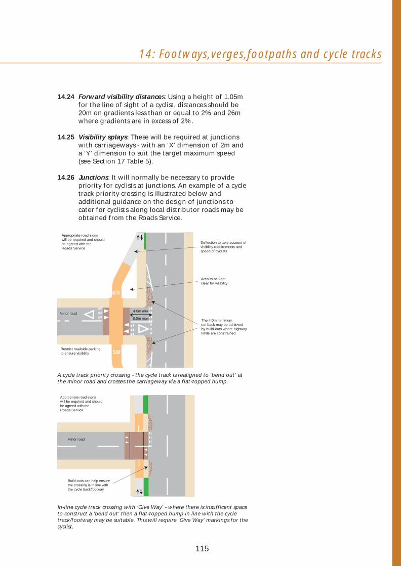
14: Footways,verges,footpaths and cycle tracks
14.24 Forward visibility distances: Using a height of 1.05m for the line of sight of a cyclist, distances should be 20m on gradients less than or equal to 2% and 26m where gradients are in excess of 2%.
14.25 Visibility splays: These will be required at junctions with carriageways - with an ‘X’ dimension of 2m and a ‘Y’ dimension to suit the target maximum speed (see Section 17 Table 5).
14.26 Junctions: It will normally be necessary to provide priority for cyclists at junctions. An example of a cycle track priority crossing is illustrated below and additional guidance on the design of junctions to cater for cyclists along local distributor roads may be obtained from the Roads Service.
Appropriate road signswill be required and should be agreed with the Deflection to take account of
Roads Service visibility requirements and speed of cyclists
Area to be kept clear for visibility
The 4.0m minimum set back may be achieved by build-outs where highway limits are constrained
Restrict roadside parkingto ensure visibility SLOW
SLOW
4.0m min
8.0m max Minor road
A cycle track priority crossing - the cycle track is realigned to ‘bend out’ at the minor road and crosses the carriageway via a flat-topped hump.
Minor road
Build-outs can help ensure the crossing is in line with the cycle track/footway
Appropriate road signs will be required and should be agreed with the Roads Service
In-line cycle track crossing with ‘Give Way’ - where there is insufficent space to construct a ‘bend out’ then a flat-topped hump in line with the cycle track/footway may be suitable. This will require ‘Give Way’ markings for the cyclist.
115

5.0m
15 Special Lay-bys
facilities for 15.01 Bus stop lay-bys should only be considered on local distributor roads and at bus termini. Where a lay-by is needed, the options of a parallel bay or shallowbuses saw tooth bay are available.
15.02 On access roads, bus stops should be at straight stretches of kerb, and lay-bys should not be provided.
BUS STOP BUS STOP
15m 18m 20m
3m
Parallel Single-Bus Layby
32.0m
R 6.4m 110
160 closing to 1300 0
5m R 25m
Shallow Saw Tooth Bus Layby
Types of bus lay-by.
Turning space
15.03 Special facilities for buses to turn may need to be provided. Typical design requirements are illustrated below.
Bus Recommended Turning Bus Turning
Capability Allowances
8m
14m6m
6.7m
12m5.3m
Bus turning allowances.
116
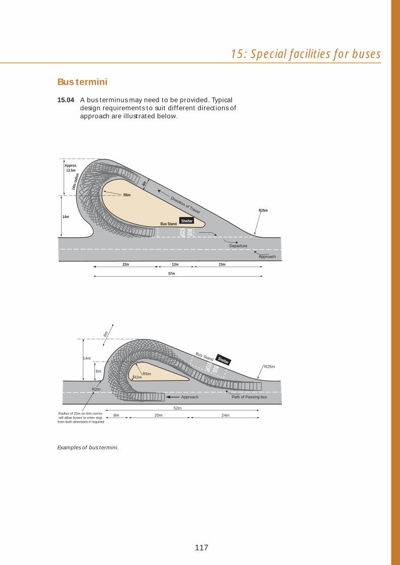
15: Special facilities for buses
Bus termini
15.04 A bus terminus may need to be provided. Typical design requirements to suit different directions of approach are illustrated below.
22m 12m 23m
57m
Approx. 13.5m
14m
R6m
R25m
4m
14m
radi
us
Approach Path of Passing bus
Bus Stand
52m
8m 20m 24m
R5m R2m
R2m
6m
14m
R25m
8m
Radius of 25m on this corner
from both directions if required
Examples of bus termini.
will allow buses to enter stop
117

16 Carriageways Main requirements
16.01 Carriageways should be designed to take into account:
• expected volumes and speeds of vehicular traffic,
• the frequency with which various types of vehicles need to pass each other,
• the design requirements for bus routes,
• the provision made for off-street and on-street parking,
• the needs of pedestrians and cyclists,
• the need to allow for unobstructed access to in-curtilage parking spaces.
16.02 The comfort and safety of cyclists and pedestrians (especially young children, the elderly and people with disabilities) should be taken into account when making decisions about carriageway gradients, vertical curves at summits and valleys, visibility at summits and design details such as drainage gratings.
16.03 The main requirements for carriageway widths and alignments are summarised in Table 3 and should be read in conjunction with the paragraphs following.
118

V
16: Carriageways
Table 3 Carriageway widths and alignments
Numbers of dwellings served by the stretch of road being considered (around)
0-200 200-400 (Local Distributor
Road)
400
Minimum width in metres 5.5(1&2) 5.5 6.7
Minimum width for bus routes in metres 6.0 6.0 6.7-7.3(3)
Carriageway narrowing - minimum width in metres
4.8 - -
Widening on bends required (Yes/No) Y(4) Y Y
Minimum curve radii in metres 30(5) 40(6) 127
Minimum vertical clearance for archways in metres
5.3(7) 5.3 5.3
Maximum gradient for roads with footways (%)
10 10 6
Maximum superelevation (%) 3 4 5
Minimum length of SAG curve per 1% change in gradient
5 10 13
(1) For a private shared driveway the minimum carriageway width is 4.1m for the first 10m, and adequate provision should be made for vehicles to turn, in order that they will not have to reverse onto the priority road.
(2) The minimum width for a shared surface is 6m.
(3) Minimum carriageway width of 6.7m where bus lay-bys are provided and 7.3m where they are not.
(4) No widening is required where no more than around 25 dwellings are served.
(5) A minimum curve radius of 25m will be acceptable where no more than around 50 dwellings are served, and a minimum of 10m where no more than around 25 dwellings are served.
(6) A minimum curve radius of 30m will be acceptable where no more than around 300 dwellings are served.
(7) Maximum vertical clearance may be reduced to 4m where no more than around 25 dwellings are served.
119

Minimum widths
16.04 The normal minimum width of a local distributor road carriageway of 6.7m will satisfactorily accommodate a bus route where bus lay-bys are provided. A minimum carriageway width of 7.3m will, however, be required if lay-bys are not provided.
16.05 A 5.5m minimum width on access roads will allow for one service vehicle to pass another and for parking on the carriageway. A minimum carriageway width of 6.0m will, however, be required on access roads that serve as bus routes.
16.06 For a shared surface, the minimum width is 6.0m, but its entrance should always be 4.8m wide.
16.07 A minimum carriageway width of 6.0m will also be required for accesses to shops and other community buildings that will be served by large delivery lorries.
16.08 Where on-carriageway cycle lanes are to be provided, these should be at least 1.5m wide in addition to the minimum widths set out above. Where possible, the width of the cycle lane should be increased to 2m.
Carriageway narrowing
16.09 Carriageway narrowing to a 4.8m minimum width allows for a car and a service vehicle to pass. This will be allowed on access roads serving up to around 200 dwellings, but only for short lengths (around 20m) and where there is no direct vehicular access - for instance, where common open space abuts the road. Carriageway narrowing to 4.8m is also acceptable on shared surfaces, but again only for short lengths. Direct vehicular access is, however, acceptable in association with narrowing on shared surfaces.
120

16: Carriageways
16.10 Carriageway narrowing will not be permitted on a bus route, on a bend or within 20m of a junction except on a shared surface road.
16.11 Carriageway narrowing less than 4.8m wide may also be acceptable in association with the design of speed restraint measures as set out in Sections 10 and 18.
Widening on bends
16.12 Widening on bends will be required where the bend curves through more than around 10 degrees. The widening may be either on both sides of the curve or on the inside - as indicated below:
Centre line radius (m) 20 or less
30 40 50 60 80
Minimum widening (m) 0.50 0.40 0.35 0.25 0.20 0.15
Gradients
16.13 For comfort, vertical curves will be required at summits and valleys.
Vertical Curve
16.14 In addition to the maximum gradients set out in Table 3:
• on the minor road at junctions, for a distance of at least twice the kerb radius, the gradient should be no more than 4%,
• for accesses to private driveways, the gradient of the access should not exceed 8% for the first 5m outside the public road boundary. The remainder of the driveway should have a gradient no greater than 10%.
16.15 For local distributor roads serving no more than around 600 dwellings, the maximum gradient may be increased to 7%.
121
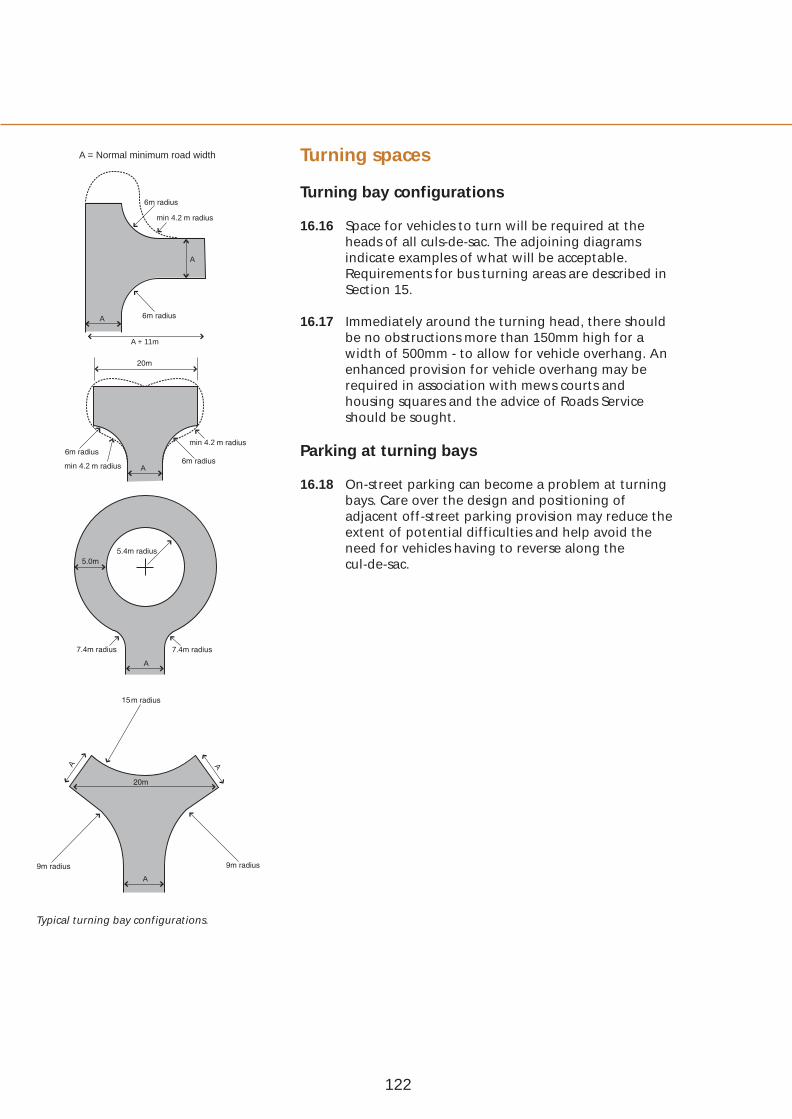
A = Normal minimum road width Turning spaces
Turning bay configurations min 4.2
16.16 Space for vehicles to turn will be required at the heads of all culs-de-sac. The adjoining diagrams
A indicate examples of what will be acceptable. Requirements for bus turning areas are described in Section 15.
A 16.17 Immediately around the turning head, there should A + 11m be no obstructions more than 150mm high for a
width of 500mm - to allow for vehicle overhang. An enhanced provision for vehicle overhang may be required in association with mews courts and housing squares and the advice of Roads Service should be sought.
min 4.2 Parking at turning bays
min 4.2 A
16.18 On-street parking can become a problem at turning bays. Care over the design and positioning of adjacent off-street parking provision may reduce the extent of potential difficulties and help avoid the need for vehicles having to reverse along the cul-de-sac.
A
A
A A
Typical turning bay configurations.
122
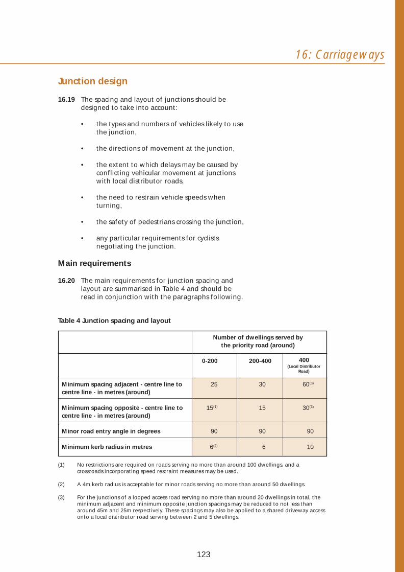
V
16: Carriageways
Junction design
16.19 The spacing and layout of junctions should be designed to take into account:
• the types and numbers of vehicles likely to use the junction,
• the directions of movement at the junction,
• the extent to which delays may be caused by conflicting vehicular movement at junctions with local distributor roads,
• the need to restrain vehicle speeds when turning,
• the safety of pedestrians crossing the junction,
• any particular requirements for cyclists negotiating the junction.
Main requirements
16.20 The main requirements for junction spacing and layout are summarised in Table 4 and should be read in conjunction with the paragraphs following.
Table 4 Junction spacing and layout
Number of dwellings served by the priority road (around)
0-200 200-400 (Local Distributor
Road)
400
Minimum spacing adjacent - centre line to centre line - in metres (around)
25 30 60(3)
Minimum spacing opposite - centre line to centre line - in metres (around)
15(1) 15 30(3)
Minor road entry angle in degrees 90 90 90
Minimum kerb radius in metres 6(2) 6 10
(1) No restrictions are required on roads serving no more than around 100 dwellings, and a crossroads incorporating speed restraint measures may be used.
(2) A 4m kerb radius is acceptable for minor roads serving no more than around 50 dwellings.
(3) For the junctions of a looped access road serving no more than around 20 dwellings in total, the minimum adjacent and minimum opposite junction spacings may be reduced to not less than around 45m and 25m respectively. These spacings may also be applied to a shared driveway access onto a local distributor road serving between 2 and 5 dwellings.
123

Right/left staggers are preferred for opposite junctions.
Crossroads are generally regarded as the most dangerous form of junction. They will only be acceptable where small numbers of dwellings are served, and provided speed restraint measures, such as a raised junction, are used.
Spacing
16.21 Right/left staggers will be preferred for opposite junctions- not left/right.
16.22 Where it is necessary or desirable to have the minor arms directly opposite each other, it will be acceptable to use a simple crossroads, provided the priority road serves no more than around 100 dwellings. In such cases, the junction should be raised or other suitable speed control measures used. Elsewhere, crossroads should be avoided and a roundabout or mini-roundabout (minimum ICD 15m) may be used.
16.23 Where it is necessary or desirable to provide a looped access road or shared driveway onto a local distributor road in the interests of promoting frontage development, reduced junction spacing requirements will be acceptable as set out in Table 4 above (see also Section 10).
Location of first access road from a junction
16.24 The first access road leading off a minor road should not be closer than 20m to the minor road junction with the priority road.
Location of driveway accesses
16.25 No driveways should enter at the bellmouth of a junction, and on minor arms of a junction should not be within twice the kerb radius.
Entry angle
16.26 A straight stretch of carriageway should be provided on the minor road for a length of at least around twice the kerb radius. Entry angles other than 90 degrees will be considered in exceptional circumstances.
Kerb radii
16.27 The diagrams on the adjacent page show different kinds of vehicles manoeuvring around junctions with different kerb radii: 10m radii for junctions with local distributor roads; 6m radii for junctions between most access roads and 4m radii for use at junctions between access roads where the minor road serves no more than around 50 dwellings.
16.28 A 4m kerb radius may also be used at the junctions between shared surface carriageways where mountable shoulders are provided.
124
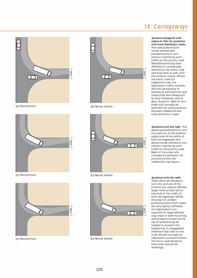
16: Carriageways
Junctions designed with radius of 10m for junctions with local distributor roads. This radius allows both refuse vehicles and pantechnicons to turn without interfering with traffic on the priority road. Pantechnicons may have difficulty in turning past vehicles on the minor road and may have to wait until the junction is clear. Where the minor road is a residential road, the lightness of traffic volumes and the infrequency of vehicles of pantechnicon size means that such delays will be very infrequent and of short duration. Radii of this order will normally be sufficient for most junctions between residential and local distributor roads.
Junctions with 6m radii. This allows pantechnicons to turn into and out of the junction using most of the width of both carriageways, and allows refuse vehicles to turn without interfering with traffic on the priority road. Radii of this order will normally be sufficient, for junctions within the residential road layout.
5.50
0 5.
500
5.50
0
5.50
0 5.
500
5.50
0
(a) Pantechnicon (b) Refuse Vehicle
(a) Pantechnicon (b) Refuse Vehicle Junctions with 4m radii. These allow all vehicles to turn into and out of the junction but require vehicles larger than private cars to use most of the width of both carriageways. Whilst this may not present problems where both roads are very lightly trafficked, the tightness of turn required for large vehicles may result in kerb mounting and precautions such as the use of bollards may be needed to prevent this happening. It is suggested therefore that radii of this order should normally be restricted to junctions where(a) Pantechnicon (b) Refuse Vehicle
125
the minor road serves no more than around 50 dwellings.
Pedestrian crossing points at junctions
16.29 Dropped kerbs should be located at the tangent point of the kerb on the minor road - or, when not practicable, on the radii.
Carriageway surfacing
16.30 Differences in surfacing, kerbs and other kinds of edge restraints should be an integral part of the design concept for the development as a whole and for the various places within it. Different surfacing materials should therefore be used to help:
• indicate the differing functions of different types of roads,
• indicate the locations of speed restraint measures,
• delineate footways, hard verges, footpaths and cycle tracks.
16.31 The aim, in most circumstances, should be to create a predominantly plain visual effect. This may be achieved with conventional materials such as asphalt and surface dressings of an appropriate colour. However, block paving should normally be used in parking areas.
16.32 Changes in materials will be needed as part of the design of most speed restraint measures and other complementary measures. For mountable shoulders, flat-topped humps, raised junctions and speed cushions, granite setts or block paving of appropriate colours will normally need to be used. These materials may also be used to reduce the apparent widths of running lanes. In addition, the carriageway surface may be overlaid with a coloured aggregate, a coloured bituminous macadam or a distinctive block surface.
16.33 Changes of surface colour and/or texture will be required for shared surfaces - to make clear to drivers that they are in surroundings where the needs of pedestrians and cyclists will take priority. Block paving is the preferred surfacing material for shared surfaces.
16.34 When using special surface treatments, care should be taken not to reduce the skid resistance of the carriageway, cause difficulties for two wheeled motor vehicles or create problems of noise for nearby households.
126

16: Carriageways
16.35 The choice of surfacing materials should also have regard to the comfort and safety of cyclists.
Carriageway edging
16.36 The following edge treatments should be used to delineate the edge of carriageways.
Standard kerb treatment on Detail to inhibit over-riding residential access roads
Granite sett kerbs on shared Bullnose kerb on shared Specialist kerb treatment surface roads surface roads on shared surface roads
Standard kerbs laid flat will not be acceptable in shared surfaces
Kerb details for use in carriageway edge treatments.
127
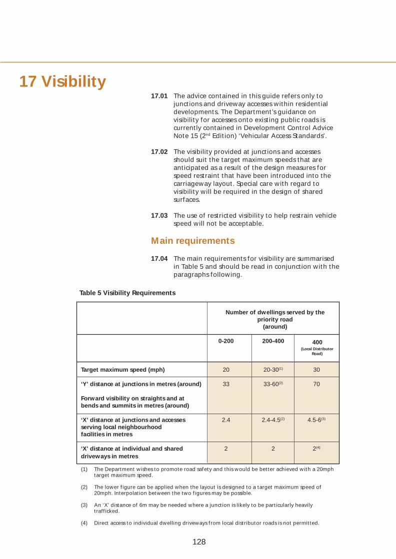
V
17 Visibility 17.01 The advice contained in this guide refers only to
junctions and driveway accesses within residential developments. The Department’s guidance on visibility for accesses onto existing public roads is currently contained in Development Control Advice Note 15 (2nd Edition) ‘Vehicular Access Standards’.
17.02 The visibility provided at junctions and accesses should suit the target maximum speeds that are anticipated as a result of the design measures for speed restraint that have been introduced into the carriageway layout. Special care with regard to visibility will be required in the design of shared surfaces.
17.03 The use of restricted visibility to help restrain vehicle speed will not be acceptable.
Main requirements
17.04 The main requirements for visibility are summarised in Table 5 and should be read in conjunction with the paragraphs following.
Table 5 Visibility Requirements
Number of dwellings served by the priority road
(around)
0-200 200-400 (Local Distributor
Road)
400
Target maximum speed (mph) 20 20-30(1) 30
‘Y’ distance at junctions in metres (around)
Forward visibility on straights and at bends and summits in metres (around)
33 33-60(2) 70
‘X’ distance at junctions and accesses serving local neighbourhood facilities in metres
2.4 2.4-4.5(2) 4.5-6(3)
‘X’ distance at individual and shared driveways in metres
2 2 2(4)
(1) The Department wishes to promote road safety and this would be better achieved with a 20mph target maximum speed.
(2) The lower figure can be applied when the layout is designed to a target maximum speed of 20mph. Interpolation between the two figures may be possible.
(3) An ‘X’ distance of 6m may be needed where a junction is likely to be particularly heavily trafficked.
(4) Direct access to individual dwelling driveways from local distributor roads is not permitted.
128
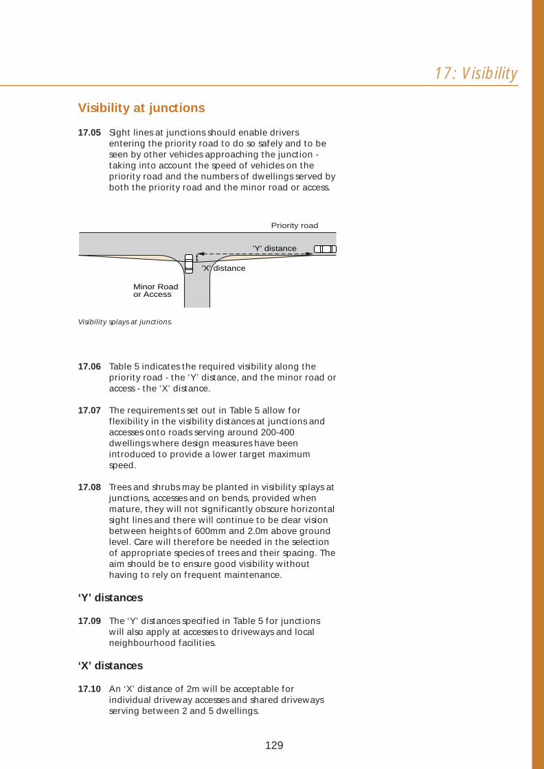
17: Visibility
Visibility at junctions
17.05 Sight lines at junctions should enable drivers entering the priority road to do so safely and to be seen by other vehicles approaching the junction taking into account the speed of vehicles on the priority road and the numbers of dwellings served by both the priority road and the minor road or access.
Priority road
'Y' distance
'X' distance
Minor Road or Access
Visibility splays at junctions.
17.06 Table 5 indicates the required visibility along the priority road - the ‘Y’ distance, and the minor road or access - the ‘X’ distance.
17.07 The requirements set out in Table 5 allow for flexibility in the visibility distances at junctions and accesses onto roads serving around 200-400 dwellings where design measures have been introduced to provide a lower target maximum speed.
17.08 Trees and shrubs may be planted in visibility splays at junctions, accesses and on bends, provided when mature, they will not significantly obscure horizontal sight lines and there will continue to be clear vision between heights of 600mm and 2.0m above ground level. Care will therefore be needed in the selection of appropriate species of trees and their spacing. The aim should be to ensure good visibility without having to rely on frequent maintenance.
‘Y’ distances
17.09 The ‘Y’ distances specified in Table 5 for junctions will also apply at accesses to driveways and local neighbourhood facilities.
‘X’ distances
17.10 An ‘X’ distance of 2m will be acceptable for individual driveway accesses and shared driveways serving between 2 and 5 dwellings.
129

Visibility turning left
17.11 A visibility radius should be provided tangential to the kerb (i.e. inside the kerb radius) where vehicles turn left into a minor road (see Table 6).
Priority road
VisibilityVisibility ZoneZone
Visibility turning left.
Table 6 Visibility Radii
Junction Deflection (Degrees)
Kerb radius 4m
Kerb radius 6m
Kerb radius 10m
80 10m 11m 19m
90 9m 10m 19m
100 8m 9m 19m
Stopping
dist
ance
Forward visibility.
Visibility on bends
17.12 Forward visibility on bends should be sufficient to enable drivers to stop if necessary to avoid collision taking into account the anticipated speeds of vehicles.
17.13 Forward visibility curves on bends should be constructed using the following procedure:
• a line should be drawn parallel to the inside kerb, 1.5m into the carriageway to represent the path of the vehicle,
• the required stopping distance commensurate with the expected speed of the vehicle should be the ‘Y’ distance given in Table 5 above and measured back along the vehicle path from tangent point A,
• the stopping distance should then be divided into equal increments of approximately 3m, and the increment points numbered in sequence,
• the same stopping distance with the same number of increments should then be repeated around the curve, finishing at a full stopping distance beyond the tangent point B,
130

17: Visibility
• the area which has to be kept clear of obstruction (with the exception of agreed planting measures) should then be constructed by joining increments of the same number together, i.e 1 to 1, 2 to 2 etc.
A
B
9 8 7 6 5 4 3 2 1
9 8
7 6
5 4
3 2
11
9 8
7
6
5
4 3
2 1
Stopping distance
Sto
ppin
g di
stan
ce
1 500
Constructing visibility curves.
Visibility above the ground
17.14 Forward visibility should be provided over the length of the stopping distance (the ‘Y’ distance in Table 5) to take account of a driver’s eye height of between 1.05m and 2m to an object height of 0.26m above the road surface. On bends, it should be checked in both the horizontal and vertical planes, between any two points in the centre of the lane on the inside of the curve.
2000
600 1050
260 Unobstructed visibility.
17.15 In addition, at junction visibility splays or verges no obstructions (with the exception of agreed planting measures) will be acceptable greater than 600mm in height which may obscure a child pedestrian.
Forward visibility at summits and valleys
17.16 At summits, clear visibility will be required for 600
600mm above the carriageway over the length of the Stopping distance stopping distance (the ‘Y’ distance in Table 5).
Visibility at summits.
131

18 Speed 18.01 Wherever possible, vehicle speeds should be restrained by appropriate changes in the layout of carriageways, reinforced by the arangement of
restraints buildings around. These include: T-junctions; looped roads; short through road and in exceptional cases, short culs-de-sac.
18.02 Speed restraint can also be achieved through the use of specifically designed measures, such as changes in the horizontal alignment of carriageways, or the use of appropriately designed vertical displacement measures. Details of a number of these measures are set out below.
18.03 In addition, the Department may be prepared to consider the use of other design measures that will restrain vehicle speeds, where it can be demonstrated that they satisfy the overall objectives of quality development and road safety. These may involve either changes in the horizontal alignment of carriageways, vertical displacement measures or a combination of both.
Changes in horizontal alignment Road sign/bollard to be agreed with Chicanes and offsets the Roads Service
18.04 Chicanes and offsets that are designed to reduce speeds sufficiently will be acceptable. To be effective, the lateral displacement of the running lane in a chicane must be severe, and the length of the displacement should be short.
Road sign/bollard to be agreed with the Roads Service
Tactile paving Parking
Dropped Kerb Crossing Footway Carriageway
Tree Tree
Parking
Footway (where appropriate)
Road sign/bollard to be agreed withDecorative bollard the Roads Servicewith reflective band
Decorative bollardChange of with reflective bandsurface material or flat-topped hump
Road sign/bollard to be agreed with the Roads Service
Typical layout of a chicane. In some cases a Typical layout of an offset. cycle by-pass will be needed.
Block Paving
Footway Tree
3.05m(min)
3.05m(min)
3.05m(min)
2.0m (min)
Footway
Tree
9.3m
132
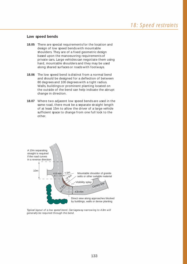
18: Speed restraints
Low speed bends
18.05 There are special requirements for the location and design of low speed bends with mountable shoulders. They are of a fixed geometric design based upon the manoeuvring requirements of private cars. Large vehicles can negotiate them using hard, mountable shoulders and they may be used along shared surfaces or roads with footways.
18.06 The low speed bend is distinct from a normal bend and should be designed for a deflection of between 80 degrees and 100 degrees with a tight radius. Walls, buildings or prominent planting located on the outside of the bend can help indicate the abrupt change in direction.
18.07 Where two adjacent low speed bends are used in the same road, there must be a separate straight length of at least 15m to allow the driver of a large vehicle sufficient space to change from one full lock to the other.
10m
Visibility splay
7.5m
4.5m Mountable shoulder of granite setts or other suitable material
4.8 min
Centre line
Direct view along approaches blocked by buildings, walls or dense planting
A 10m separating straight is required if the road curves in a reverse direction
7.5m
4.8 min
Typical layout of a low speed bend. Carriageway narrowing to 4.8m will generally be required through the bend.
133
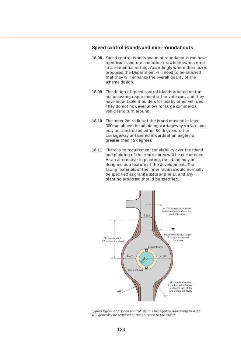
Speed control islands and mini-roundabouts
18.08 Speed control islands and mini-roundabouts can have significant land-use and other drawbacks when used in a residential setting. Accordingly where their use is proposed the Department will need to be satisfied that they will enhance the overall quality of the scheme design.
18.09 The design of speed control islands is based on the manoeuvring requirements of private cars, and they have mountable shoulders for use by other vehicles. They do not however allow for large commercial vehicles to turn around.
18.10 The inner 2m radius of the island must be at least 300mm above the adjoining carriageway surface and may be constructed either 90 degrees to the carriageway or tapered inwards at an angle no greater than 45 degrees.
18.11 There is no requirement for visibility over the island and planting of the central area will be encouraged. As an alternative to planting, the island may be designed as a feature of the development. The facing materials of the inner radius should normally be specified as granite setts or similar, and any planting proposed should be specified.
Keep left sign
Keep left sign
7.1m4.1m
4.8m
20m
3m
2.0m
Maximum effective length of straight measured
from here
A 10m straight is required between the island and the
start of a curve
Mountable shoulder to be formed with inner
and outer radii of 3m and 20m respectively
No access within 12m of centre island
Typical layout of a speed control island. Carriageway narrowing to 4.8m will generally be required at the entrance to the island.
134
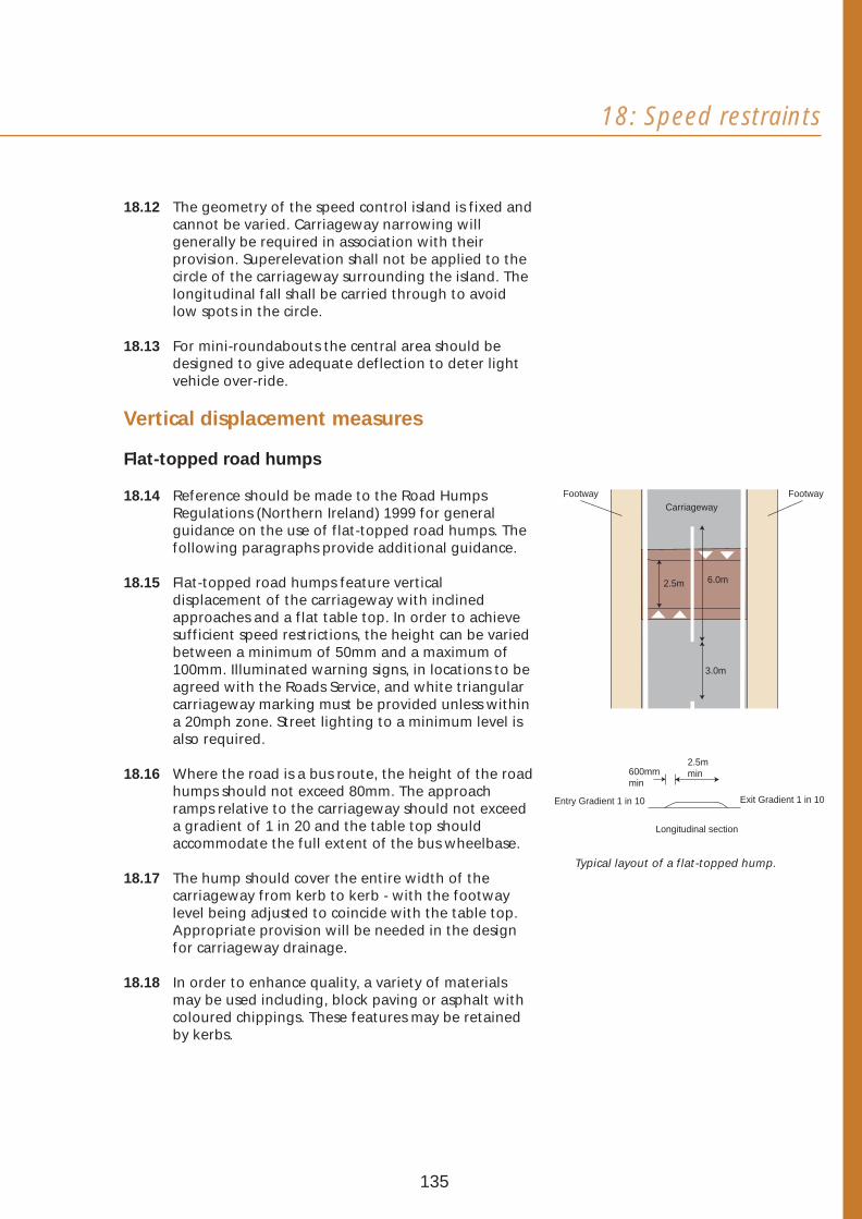
18: Speed restraints
18.12 The geometry of the speed control island is fixed and cannot be varied. Carriageway narrowing will generally be required in association with their provision. Superelevation shall not be applied to the circle of the carriageway surrounding the island. The longitudinal fall shall be carried through to avoid low spots in the circle.
18.13 For mini-roundabouts the central area should be designed to give adequate deflection to deter light vehicle over-ride.
Vertical displacement measures
Flat-topped road humps
18.14 Reference should be made to the Road Humps Regulations (Northern Ireland) 1999 for general guidance on the use of flat-topped road humps. The following paragraphs provide additional guidance.
18.15 Flat-topped road humps feature vertical displacement of the carriageway with inclined approaches and a flat table top. In order to achieve sufficient speed restrictions, the height can be varied between a minimum of 50mm and a maximum of 100mm. Illuminated warning signs, in locations to be agreed with the Roads Service, and white triangular carriageway marking must be provided unless within a 20mph zone. Street lighting to a minimum level is also required.
18.16 Where the road is a bus route, the height of the road humps should not exceed 80mm. The approach ramps relative to the carriageway should not exceed a gradient of 1 in 20 and the table top should accommodate the full extent of the bus wheelbase.
18.17 The hump should cover the entire width of the carriageway from kerb to kerb - with the footway level being adjusted to coincide with the table top. Appropriate provision will be needed in the design for carriageway drainage.
18.18 In order to enhance quality, a variety of materials may be used including, block paving or asphalt with coloured chippings. These features may be retained by kerbs.
Footway
3.0m
6.0m2.5m
Footway Carriageway
2.5m 600mm min min
Entry Gradient 1 in 10 Exit Gradient 1 in 10
Longitudinal section
Typical layout of a flat-topped hump.
135

Raised junctions
18.19 Raised junctions are a form of flat-topped hump and the design dimensions outlined above therefore apply.
18.20 Where a raised junction is on a bus route it should be designed so that a bus giving way at the minor arm will have all its wheels on the flat topped area.
18.21 Where pedestrian crossing places are needed, tactile paving should be provided on the footway.
18.22 Generally block paving is the preferred material, but asphalt can be used provided the ramped raised effect is achieved, and there is a colour or texture change through the junction. This will alert drivers and can assist pedestrians whose vision is impaired.
Footway
Pedestrian crossover within the junction table
Tactile paving
Carriageway
TP = Tangent Point TP
TP
TP
TP
Block paving
bollards
bollards
Tactile paving
Typical layout of a raised junction.
Speed cushions
18.23 Generally in the order of 1.7m to 1.9m wide, speed cushions allow the front and rear wheels of HGVs, buses and larger emergency vehicles to straddle the raised area. Cars cross the cushions with at least one wheel of each axle on the cushion. Cyclists can pass unhindered.
18.24 Some high-sided vehicles may be caused to tilt, so street furniture, including lighting, must be set to the rear of the footway. Connections to private driveways must be avoided within the area occupied by a speed cushion.
136
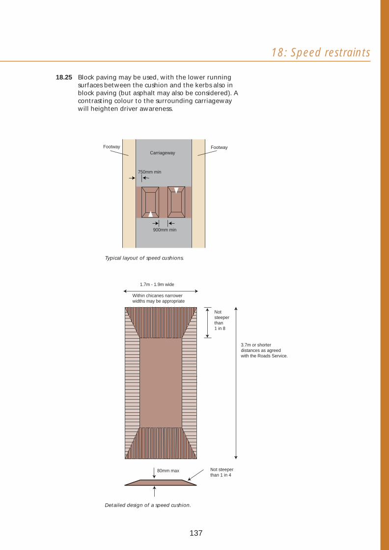
18: Speed restraints
18.25 Block paving may be used, with the lower running surfaces between the cushion and the kerbs also in block paving (but asphalt may also be considered). A contrasting colour to the surrounding carriageway will heighten driver awareness.
750mm min
900mm min
FootwayFootway Carriageway
Typical layout of speed cushions.
1.7m - 1.9m wide
3.7m or shorter distances as agreed with the Roads Service.
Within chicanes narrower widths may be appropriate
Not steeper than 1 in 8
Not steeper than 1 in 4
80mm max
Detailed design of a speed cushion.
137

Complementary measures
18.26 Central refuges with bollards and beacons may be used
along local distributor roads to narrow the running lanes
and help pedestrians to cross.
Dimensions in millimetres
kerb (0-5mm face)
Base-lit bollard with standard shear base sign dia. 610 (left handed)
450mm Transitional Dropped kerbs
450mm
2000 (1200min)
6000 (4200 min) Illuminated refuge beacon
Tactile paving
2000 (1500min)
Dropped kerbs (0-55mm face) 3050
Footway
Bituminous macadam
infill
Dimensions in millimetres Local widening (1 in 20 taper)
Illuminated refuge beacon
Tactile paving
Base-lit bollard with standard shear base sign dia. 610 (left handed)
6000 (4200min)
Typical layout and design of central refuges.
138

18: Speed restraints
18.27 Within traffic calmed areas, footways may be extended as build-outs on one or both sides, to narrow the overall carriageway width. These build-outs can be used: to help rationalise parking; as landscape features; or as safe pedestrian crossing points - often in conjunction with other speed restraint measures such as flat-topped humps.
Footway
Footway
Flat-topped hump
Footway
Carriageway
Decorative Decorative bollard bollard with with reflective reflective band band
Minimum width 2.4m
Cyc
le b
ypass
3m
to
5m
0.7
5m
Carriageway 7
.88
m
4m
0.5W
Footway
Road sign/bollard to be agreed with the Roads Service
Build-outs to narrow the carriageway, Typical layout of a build-out also providing a pedestrian crossing with a cycle by-pass. point and space for tree planting.
139

19 Shared 19.01 Footways alongside carriageways may be omitted where it is desirable to create a shared surface with an intimate human scale suitable for use by
surfaces pedestrians, cyclists and vehicles. All shared surfaces should be carefully designed to make it clear to drivers that they are in an area where the needs of pedestrians and cyclists will take priority.
19.02 Shared surfaces may be provided in the form of a mews court or a housing square. At lower densities, shared surfaces that make appropriate provision for services underground in verges in front gardens (commonly referred to as ‘service strips’) will also be acceptable, but only where the building density will be no more than around 13 houses per hectare (see Section 12).
19.03 The carriageway of a shared surface should serve no more than around 25 dwellings - or 50 dwellings for looped or through roads where junctions with roads with footways are located at each end of the shared surface.
Visual character
19.04 Differences between the visual character of shared surfaces and roads with footways should be clearly emphasised by the design - for instance, by using design features such as closely spaced buildings or gateways at entrances to shared surfaces - and by the use of different surface colour, textures and materials.
Entrances
19.05 Possible designs for junctions at the entrance to a shared surface include:
• extending the footways along the main road for a short distance into the shared surface - with a ramped entrance or other appropriate entry treatment to be agreed with the Roads Service1
- and a change in carriageway surfacing and kerb detailing,
• carrying the footway along the main road across the entrance to the shared surface - in the form of a ramp or other appropriate entry treatment to be agreed with the Roads Service1 - and a change in carriageway surfacing and kerb detailing,
• at the junction between two shared surfaces, using tight kerb radii with mountable shoulders.
Examples of shared surfaces.
1 For further information on appropriate entry treatments for shared surfaces, see DOT Traffic Advisory Leaflet 2/94: Entry Treatments.
140

19: Shared surfaces
Transitional footway
Examples of acceptable junction designs at the entrance to a shared surface.
Configuration
19.06 Shared surfaces should be wide enough to allow pedestrians, cyclists and vehicles to pass each other comfortably and for vehicles to manoeuvre. The normal minimum width for a shared surface is 6.0m, but it should always be 4.8m wide at its entrance. Carriageway narrowing to 4.8m is also acceptable, but only for short lengths (around 20m).
19.07 A 500mm paved margin will be required wherever no verges are provided alongside the shared surface such as in mews courts and housing squares. An enhanced provision may also be required for vehicle overhang at turning bays and the advice of the Roads Service should be sought.
19.08 The target maximum speed for a shared surface should be well below 20mph. Appropriate measures for speed restraint should be used and spaced no more than around 40m apart.
19.09 Mountable shoulders may be used to help reduce speeds at junctions between shared surfaces.
19.10 Spaces free from vehicular traffic may be provided for instance by using the layout configuration, Mountable shoulders at the junction of two
bollards, benches or bicycle parking posts to keep shared surfaces - these should be used in
vehicles away from dwelling entrances. association with tight kerb radii.
Block paving
Priority road carriageway
Transitional kerb
Bollard
Ramped Entrance
Shared surface with a surface treatment different from priority road carriageway
Footway Ramped entrance
Priority road carriageway
Shared surface with a surface treatment different from priority road carriageway
141

Visibility
19.11 Visibility splays should be provided at dwelling entrances adjacent to the shared surface where accesses to garages and hardstandings occur, and where footpaths or cycle tracks cross the shared surface. The splays should normally provide:
• an ‘X’ distance of at least 2m,
• a ‘Y’ distance of at least 33m.
Services underground
19.12 Routes for services underground may be located in verges alongside the shared surface carriageway subject to the conditions set out in Paragraphs 12.10 and 12.11.
19.13 Where verges are not provided, such as in mews courts and housing squares, services underground may be located beneath the shared surface carriageway.
Surfacing and edge restraints
19.14 The shared surface should always be distinguished from the carriageways along other roads by changes in colour and texture.
19.15 The surfacing materials and edge restraints should not give the impression of the road being divided into a carriageway and footways. However, the different functions of different parts of the shared surface - for instance, the running lanes and communal parking spaces - may be demarcated by contrasting paving materials and other elements such as trees, bollards, cycle tracks, ground cover shrubs and drainage channels.
19.16 The edge treatment around the shared surface should normally be in contrasting materials and significantly lower in height than those used along access roads with footways.
142

19: Shared surfaces
143
20 Parking spaces: numbers and dimensions
20.01 This section sets out the Department’s requirements for the total numbers of parking spaces to be provided for residents, visitors and other callers.
Underlying principles
20.02 To help avoid the danger, nuisance, inconvenience and hazards caused by indiscriminate on-street parking, there will be a need to provide:
• sufficient numbers of in-curtilage and/or off-street communal parking spaces for residents’ and visitors’ cars,
• spaces for short-term parking by service vehicles and casual callers on, or alongside, carriageways giving direct access to dwellings,
• routes from parking spaces to dwelling entrances, or other destinations, that are more convenient to use than parking on carriageways,
• parking spaces close to and within sight of the dwellings they are intended to serve,
• off-street spaces for cars and provision for bicycles at community buildings.
20.03 Sufficient space should be provided for bicycle parking within dwellings, garages or outside. Communal bicycle stands should normally be provided in association with apartment developments.
Numbers of spaces required
20.04 Tables 7 and 8 set out the normal car parking provision required for residents and callers in developments on green-field sites or in low-density areas. Lesser provision may be acceptable in inner urban locations and other high-density areas. In special circumstances, in some inner urban locations, ‘car-free’ developments may be considered appropriate - where it can be demonstrated that households will not own a car or will keep it elsewhere.
20.05 Tables 7 and 8 take account of the sizes and types of dwelling to be provided, and the proportions of spaces to be provided within house curtilages and/or in communal grouped parking spaces.
20.06 The provision required beyond house curtilages should be located in off-street communal parking areas or parking bays contiguous with carriageways.
144

20: Parking spaces: numbers and dimensions
20.07 A carriageway width of 5.5m is intended to allow for parking by casual callers, and these spaces may be counted towards the total provision required provided:
• they are clearly indicated on the submitted layout plan,
• they do not obstruct entrances to driveways or block access along the carriageway.
20.08 Where in-curtilage parking is provided and driveways, by virtue of their length, can accommodate 2 or more cars parking end to end, no more than 2 of these spaces will be counted towards the in-curtilage provision.
20.09 Garages will only be counted towards the in-curtilage provision, where they are large enough to both accommodate cars and make provision for general storage, or alternatively, provision for general storage can be made elsewhere within the curtilage.
20.10 Each part of the layout should be self-sufficient with regard to its parking provision. For larger developments it will therefore be necessary to consider each part of the development separately to arrive at an appropriate total requirement.
20.11 Table 7 sets out the parking requirements for apartments and terraced houses that only have communal provision. Table 8 sets out the requirements for houses having one or more parking spaces within the curtilage. The total requirements given include spaces for residents, visitors and other callers. Worked examples are given for each table.
145

Table 7 Total number of parking spaces per dwelling required for apartments and houses that have only communal parking provision.
Dwelling size (bedrooms)
Total no. of parking spaces required per
dwelling (unassigned spaces)
Total no. of parking spaces required per
dwelling (assigned spaces)(1)
Apartments Bed sit and 1 bed 1.25 1.5
2 bed 1.5 1.75
3 bed 1.75 2.0
Terraced houses 1 and 2 bed 1.5 1.75
3 bed 1.75 2.0
(1) Communal parking areas with assigned spaces will not be adopted for future maintenance by the Roads Service.
Worked examples for Table 7
20.12 Two examples of how to use Table 7 are given below. The first is for a group of 30 apartments, 15 of which are 2-bed and 15 are 3-bed. All have only unassigned communal parking provision. The total requirement derived from Table 7 is for 49 spaces - made up as follows:
2-bed apartments (15 x 1.5 spaces) 22.5 spaces
3-bed apartments (15 x 1.75 spaces) 26.25 spaces
Total requirement 48.75 spaces
(rounded up) 49.00 spaces
20.13 The second, using the above example, is where one parking space is assigned to each apartment. The total number of parking spaces required would be 56 made up as follows:
2-bed apartments (15 x 1.75 spaces) 26.25 spaces
3-bed apartments (15 x 2 spaces) 30.00 spaces
Total requirement 56.25 spaces
(rounded down) 56.00 spaces
146

20: Parking spaces: numbers and dimensions
Table 8 Total number of parking spaces per dwelling required for houses that have in-curtilage parking provision.
Dwelling size (bedrooms)
Total no. of parking spaces required per dwelling
No. of in-curtilage spaces provided 1 2 3 4
Terraced houses 1 bed 1.75 2.25
2 and 3 bed 2 2.5
Semi-detached houses 3 bed 2.25 2.5 3.25 4.25
4 bed 2.5 2.75 3.5 4.25
Detached houses 3 bed 2.5 2.75 3.5 4.25
4 bed 2.75 3 3.75 4.5
5 bed 3 3.25 3.75 4.5
Worked examples for Table 8
20.14 Two examples of how to use Table 8 are given below. The first is for a group of eighteen 3-bed semidetached houses, each with one in-curtilage parking space. The total requirement derived from Table 8 is for 40.5 spaces (18 x 2.25 spaces per dwelling) – rounded up to 41, and made up as follows:
In-curtilage spaces (18 x 1.0 spaces) 18 spaces
Unassigned communal
(18 x 1.25 spaces) 22.5 spaces
Total requirement 40.5 spaces
(rounded up) 41.00 spaces
20.15 Second, if two in-curtilage spaces per dwelling had been provided, the total required would be 45 spaces (18 x 2.5) – made up as follows:
In-curtilage spaces (18 x 2 spaces) 36.00 spaces
Unassigned communal
(18 x 0.5 spaces) 9.00 spaces
Total requirement 45.00 spaces
147

700mm 75
0mm
200 R.max
250
min
50mm diamild steel
Option 1:Stand bolted to Option 2:the ground Stand embedded
into ground
Sheffield Stand.
1000mm
Stands welded to steel runners
‘Toast Rack’ of Sheffield Stands.
Bicycle parking spaces
20.16 Supports: Provision should normally be made for bicycles to be supported independently of each other. To promote security, the parking facility should make it possible for the frame of the bicycle and, if possible, both wheels to be locked to the fixture.
20.17 A recommended bicycle parking facility is the ‘Sheffield Stand’. Other facilities may also be acceptable and the advice of the Roads Service should be sought.
In-curtilage carports and garages
20.18 Minimum internal length: 5m for carports and garages.
20.19 Minimum internal width: 3m for single, and 5.5m for double carports and garages.
20.20 Storage provision: If storage provision (especially for bicycles and garden equipment such as lawn mowers) is not made elsewhere, the garage or carport will need to make such provision:
20.21 For garages, the preferred location for the storage space will be down one side of the garage (to make it accessible without the car having to be moved) and, in this case:
• the minimum internal width will need to be 4m for single garages, and 6.2m for double garages.
20.22 For carports, the store should be located either to one side or at the end of the carport, and be accessible without having to move the car, and in such cases:
• a 1.75m wide access space should be available in front of the store door (this space may be part of the path required to gain access to the front door), and
• a path at least 900mm wide (in addition to the width of the carport) should be provided to allow access to the front door of the house.
148
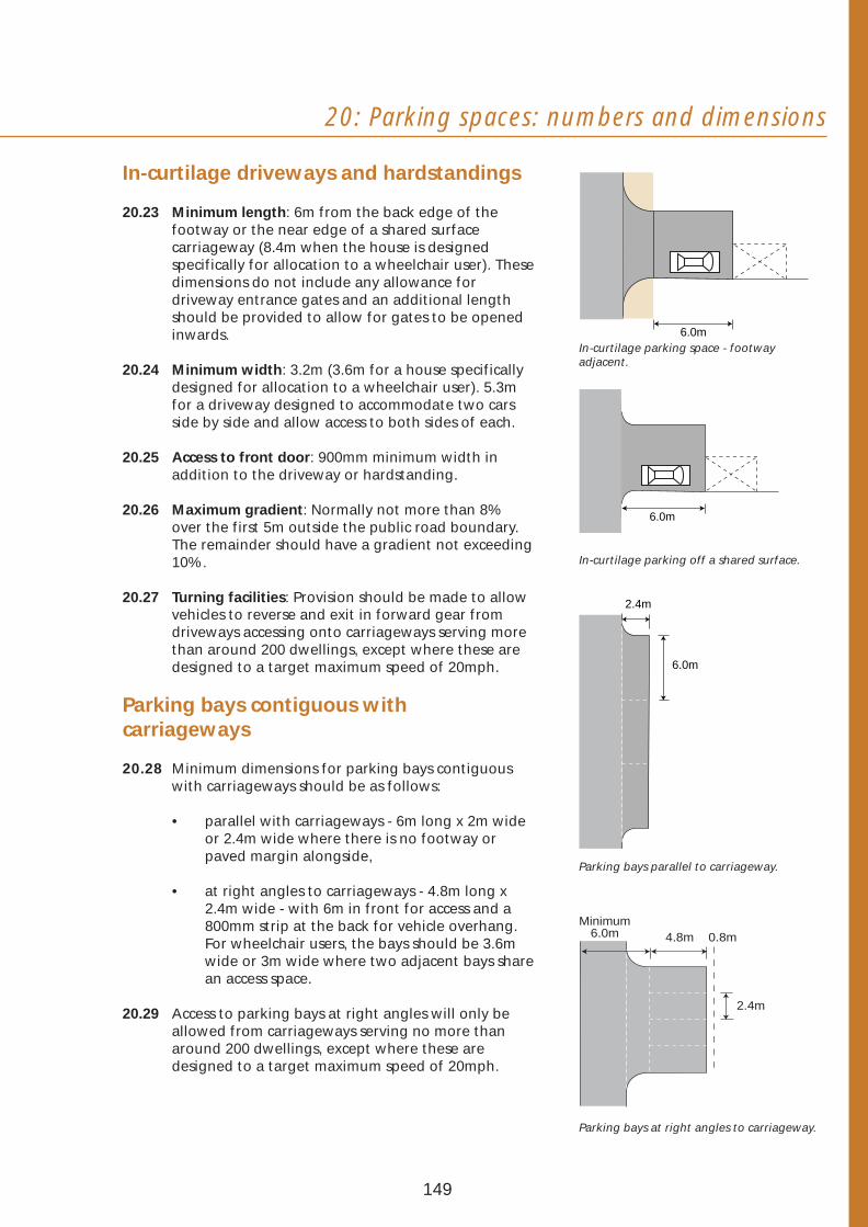
20: Parking spaces: numbers and dimensions
In-curtilage driveways and hardstandings
20.23 Minimum length: 6m from the back edge of the footway or the near edge of a shared surface carriageway (8.4m when the house is designed specifically for allocation to a wheelchair user). These dimensions do not include any allowance for driveway entrance gates and an additional length should be provided to allow for gates to be opened
6.0minwards. In-curtilage parking space - footway
20.24 Minimum width: 3.2m (3.6m for a house specifically adjacent.
designed for allocation to a wheelchair user). 5.3m for a driveway designed to accommodate two cars side by side and allow access to both sides of each.
20.25 Access to front door: 900mm minimum width in addition to the driveway or hardstanding.
20.26 Maximum gradient: Normally not more than 8% over the first 5m outside the public road boundary. The remainder should have a gradient not exceeding 10%.
6.0m
In-curtilage parking off a shared surface.
20.27 Turning facilities: Provision should be made to allow 2.4m vehicles to reverse and exit in forward gear from driveways accessing onto carriageways serving more than around 200 dwellings, except where these are designed to a target maximum speed of 20mph.
Parking bays contiguous with carriageways
20.28 Minimum dimensions for parking bays contiguous with carriageways should be as follows:
• parallel with carriageways - 6m long x 2m wideor 2.4m wide where there is no footway orpaved margin alongside,
Parking bays parallel to carriageway.
• at right angles to carriageways - 4.8m long x2.4m wide - with 6m in front for access and a
Minimum 800mm strip at the back for vehicle overhang. 6.0m 4.8m 0.8mFor wheelchair users, the bays should be 3.6mwide or 3m wide where two adjacent bays sharean access space.
20.29 Access to parking bays at right angles will only be allowed from carriageways serving no more than around 200 dwellings, except where these are designed to a target maximum speed of 20mph.
6.0m
2.4m
Parking bays at right angles to carriageway.
149
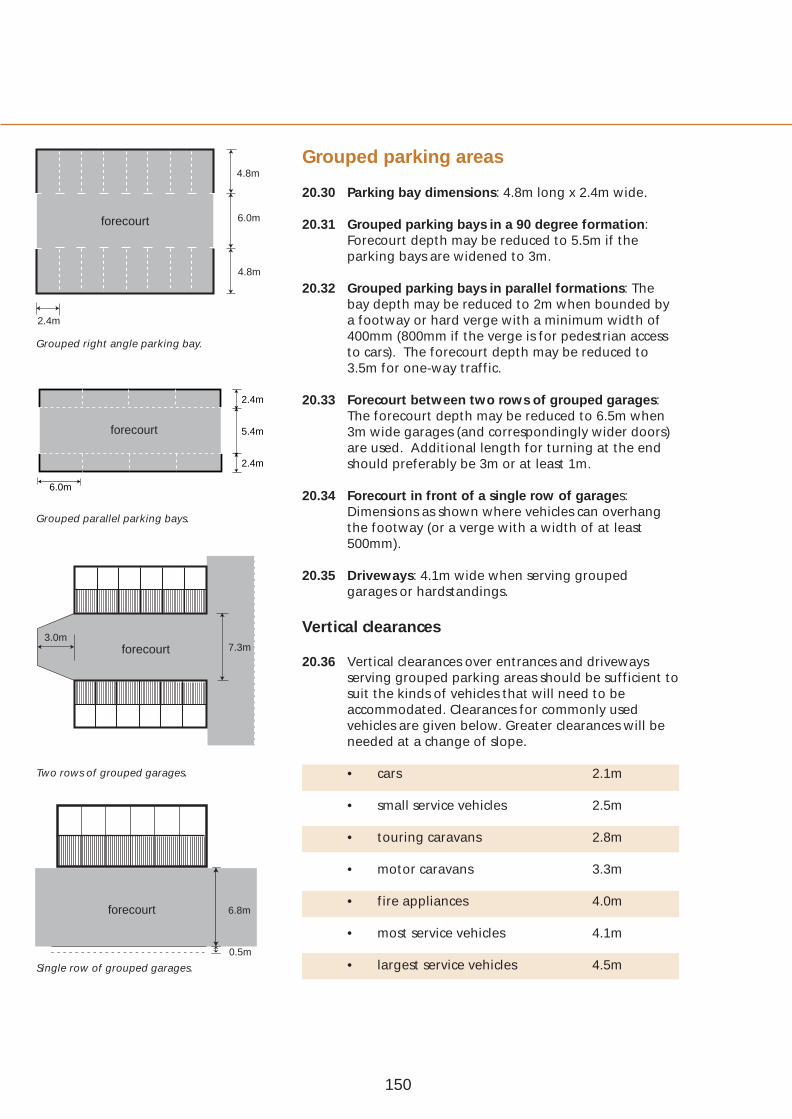
forecourt
2.4m
Grouped right angle parking bay.
6.0m
forecourt
Grouped parallel parking bays.
3.0m 7.3mforecourt
Two rows of grouped garages.
Grouped parking areas4.8m
20.30
6.0m 20.31
4.8m
20.32
2.4m 20.33
5.4m
2.4m
20.34
20.35
Parking bay dimensions: 4.8m long x 2.4m wide.
Grouped parking bays in a 90 degree formation: Forecourt depth may be reduced to 5.5m if the parking bays are widened to 3m.
Grouped parking bays in parallel formations: The bay depth may be reduced to 2m when bounded by a footway or hard verge with a minimum width of 400mm (800mm if the verge is for pedestrian access to cars). The forecourt depth may be reduced to 3.5m for one-way traffic.
Forecourt between two rows of grouped garages: The forecourt depth may be reduced to 6.5m when 3m wide garages (and correspondingly wider doors) are used. Additional length for turning at the end should preferably be 3m or at least 1m.
Forecourt in front of a single row of garages: Dimensions as shown where vehicles can overhang the footway (or a verge with a width of at least 500mm).
Driveways: 4.1m wide when serving grouped garages or hardstandings.
Vertical clearances
20.36 Vertical clearances over entrances and driveways serving grouped parking areas should be sufficient to suit the kinds of vehicles that will need to be accommodated. Clearances for commonly used vehicles are given below. Greater clearances will be needed at a change of slope.
• cars 2.1m
• small service vehicles 2.5m
• touring caravans 2.8m
• motor caravans 3.3m
• fire appliances 4.0m
• most service vehicles 4.1m
• largest service vehicles 4.5m
forecourt
0.5m
6.8m
Single row of grouped garages.
150

20: Parking spaces: numbers and dimensions
Demarcation of communal parking spaces
20.37 Communal parking spaces should be demarcated to help avoid the waste of space and obstructions that can be caused by indiscriminate parking. Demarcation can be achieved by the use of changes in surfacing materials or rows of setts. Where communal parking spaces are to be provided on shared surfaces, these will need to be clearly distinguished from the space required for pedestrians, cyclists and vehicles.
20.38 A variety of materials should also be used to demarcate the forecourts, drainage channels and running lanes in the access aisles. A change of surface material or a row of setts or paviors will be required to identify boundaries with adopted areas.
20.39 Paving materials in the parking bays should be selected to minimise the visual impact and damage that can be caused by oil spillage.
151

21 Utilities’ Electricity
21.01 Work in the vicinity of electrical cables or equipment, services whether underground or overhead, can involve those concerned in considerable danger. The greatest care must be exercised not to come too close, or to bring materials, appliances or tools too close, as workmen, and indeed other persons not directly concerned, may be at risk of a serious or even fatal accident. Before any works commence on site, developers should therefore consult with the electricity supply company.
21.02 Where it is necessary to provide an electricity substation in the development, the location should be agreed at an early stage with the Department and the electricity supply company1. Particular care will be necessary in the design to minimise the visual impact of new substations and to ensure that appropriate provision is made for future servicing and maintenance. Special arrangements may also be needed for the security of the equipment and to ensure public safety. Where fencing is required, screen planting of appropriate species will be necessary.
21.03 Cables should generally be laid and jointed in areas that will be adopted for future maintenance by the Roads Service.
Lamp standard Dimensions in mm
2000
1720
280 170 295 295 270 260 430
1550
1255
960
690
430
350
900
600
250
60045
0
Bou
ndar
y
Out
side
sto
p va
lve
Cab
le T
V
Gas
Tele
com
ms
Wat
er
Ele
c hv
E
lec
lv
Ele
c lv
All
pos'
n
Carriageway
Location of underground services.
1 Developers may find it useful to refer to the document entitled ‘Provision of Substations by Northern Ireland Electricity in New Developments’, available from Northern ireland Electricity.
152
21: Utilities’ services
Gas
21.04 Work in the vicinity of gas pipes can involve considerable danger, as damage can cause leaks resulting in fire, explosion or loss of supply. Developers should therefore consult with the gas utility provider well in advance of any works commencing on site. The location of gas pipes should be determined before any building operations are commenced and trial holes dug by hand to determine the exact position before any works of excavation start. The greatest care must be exercised to ensure mechanical excavation is not carried out within 3m of gas mains. Hand held tools should not be used within 1.5m of a gas pipe.
21.05 Where it is intended to provide a gas supply in the development, developers should liaise with the gas utility provider.
Water
21.06 Large diameter pvc water pipes will normally only accommodate a laying radius of 280m, and ductile iron pipes a minimum of 70m radius. Although small diameter pipes have some flexibility, bends will normally be needed for tighter radii. At turning heads, it may be necessary for water mains to pass under the carriageway.
21.07 Stop-cock boxes should be provided for each dwelling at or near the boundary, and are best sited at the edge of the private drive.
21.08 The siting of fire hydrants must be carried out in consultation with the Water Service and the Fire Service.
Sewers
21.09 Sewers must be laid in straight lines between manholes and should be sited in adopted or paved areas.
Telecommunications
21.10 Telecommunications services should normally be underground. Developers may reduce the costs of undergrounding by providing suitable pipe ducts from the main cable run to the lead-in point at each dwelling. In large developments, sites for call boxes may be required.
153
Lighting
The lighting plan
21.11 Detailed advice on street lighting is currently contained in British Standard 5489, which is published in ten parts. The most recent edition of each part should be consulted.
21.12 The proposed standard of lighting, light source, general lighting layout and electricity supply arrangements should be discussed at an early stage in the design process with the Roads Service. Details of the luminaire performance, illuminance or luminance calculations, and electrical design will also need to be agreed.
Siting of equipment
21.13 All equipment must be sited in or under areas to be adopted. Columns should normally be set at the rear of footways and within footpaths. Particular care should be exercised when columns are to be located near to overhead or underground electricity equipment, and the electricity supply company should be consulted for advice on clearances and procedures.
Electricity supply
21.14 The usual arrangement is for the lighting to have a separate cable system that derives its supply from the electricity mains, via a suitably sited cubicle (commonly referred to as a mini-pillar), which contains isolation and photo-electric switching equipment.
154

21: Utilities’ services
155

Page 156

Page 157
Creating Places
Appendices

Appendix A: Definitions
The urban road network
Primary distributors Form the primary network for the town as a whole and all longer-distance traffic movements to, from and within the town are channellised onto such roads.
District distributors Distribute traffic between the residential, industrial and principal business districts of the town and form the link between the primary network and the roads within residential areas
Local distributors Distribute traffic within districts. In residential areas, they generally form the link between district distributors and residential access roads.
Residential access roads Link dwellings and their associated parking areas and common open spaces to distributors. Such roads are referred to as ‘access’ roads in this guide. They may serve up to around 400 dwellings and provide direct access to dwellings. These roads may serve as bus routes - subject to an appropriately enhanced specification where necessary.
Shared surfaces Access roads without footways that may serve no more than around 25 dwellings - or 50 dwellings for looped or through roads where junctions with roads with footways are located at each end of the shared surface (see also below).
Shared driveways An access road or an unadopted road serving the driveways of between 2 and 5 houses.
Driveways Unadopted areas providing access to garages or other parking spaces within the curtilage of an individual house.
158
Other definitions
Carriageways Those parts of roads intended primarily for use by vehicles.
Shared surfaces Carriageways designed for shared use by pedestrians, cyclists and vehicles (see also above).
Footways Those parts of roads for use by pedestrians and which generally are parallel with the carriageways, and separated by a kerb, or a verge and a kerb.
Footpaths Those pedestrian routes located away from carriageways and not associated with routes for motor vehicles.
Cycle lanes Those parts of carriageways allocated for use by pedal cyclists
Cycle tracks Routes for use by pedal cyclists, with or without rights of way for pedestrians.
Segregated cycle tracks Routes for use by pedal cyclists adjacent to footways or footpaths, and separated from them by a feature such as a verge, kerb or a continuous raised white line.
Technical terms
Bellmouth The area formed by the widening of a road at its junction with another road. This widening is normally achieved through the use of a specified kerb radii.
Deflection The angle through which a road changes direction at curves, bends or roundabouts.
Direct access Vehicular access from private property onto the public road.
Horizontal alignment The direction and course of the centre line of a road on plan.
159
Appendix A: Definitions
Lay-by That part of a road set aside for vehicles to draw out of the traffic lanes and wait for short periods.
Mountable shoulder An area abutting the carriageway on the inside of a bend constructed to carry wheel loads and accommodate the turning manoeuvres of large vehicles.
Sight line A line either on plan or in profile that delineates the area within which an object becomes visible to an observer.
Tangent point The point where straight alignment ceases and curvature begins. Also a point of change of hand or type of curvature.
Target maximum speed The maximum speed of vehicles considered appropriate to the number of dwellings served by a road, from which the guidance on acceptable distance between speed restraint measures is derived.
Turning bay That part of a road normally sited at the head of a cul-de-sac intended for the turning of vehicles.
Verge That part of a road normally adjacent to the carriageway in the form of a grassed area which may include planting, or a hard margin.
Visibility Uninterrupted sight between vehicles or between vehicles and pedestrians.
Visibility splay The area of land at a junction or access over which it is necessary to provide visibility.
160

Appendix B: Information required
General
1 The information to be submitted to the Department when planning permission is being sought will not exceed what any developer who pursues quality in design will normally need to produce, namely:
• plans, sections and photographs produced during the appraisal of the site and its setting to illustrate clearly the existing landscape and visual character of the site (material along the lines set out in Sections 1 and 2),
• a concept plan illustrating the scheme layout in diagrammatic form, supported by sketch plans and a written statement outlining out the overall design concept and objectives for the development. For larger schemes a comprehensive master-plan will be necessary,
• axonometrics, perspectives or other visual media such as photomontages to give an accurate impression of the three-dimensional character of what is being proposed,
• a 1/500 layout plan and sections and elevations at key places - to indicate clearly the intended functions and form of the different parts of the layout.
Planting
2 A separate planting plan will normally need to be produced. This should include a detailed schedule of works for all trees, shrubs and other plant material, and indicate the botanical (Latin) names - including both the genera and the species - together with the size and height at the time of planting, the presentation, the location, the spacings and the numbers. In the case of trees, the girth measured 1m above ground and the height of the clear stem should also be included in the schedule. The estimated mature heights and spreads of existing trees to be retained and new tree planting may also need to be indicated on plan.
161
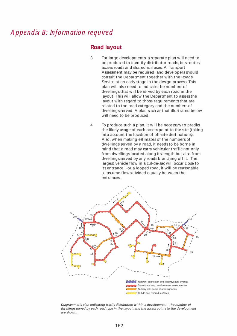
Appendix B: Information required
Road layout
3 For large developments, a separate plan will need to be produced to identify distributor roads, bus routes, access roads and shared surfaces. A Transport Assessment may be required, and developers should consult the Department together with the Roads Service at an early stage in the design process. This plan will also need to indicate the numbers of dwellings that will be served by each road in the layout. This will allow the Department to assess the layout with regard to those requirements that are related to the road category and the numbers of dwellings served. A plan such as that illustrated below will need to be produced.
4 To produce such a plan, it will be necessary to predict the likely usage of each access point to the site (taking into account the location of off-site destinations). Also, when making estimates of the numbers of dwellings served by a road, it needs to be borne in mind that a road may carry vehicular traffic not only from dwellings located along its length but also from dwellings served by any roads branching off it. The largest vehicle flow in a cul-de-sac will occur close to its entrance. For a looped road, it will be reasonable to assume flows divided equally between the entrances.
207 35
105
102
47
18
67
42
10 20
26
12
8 8
14
49
29
27
12 32
104
38
21
62 15
15
213
Network connector, two footways and avenue Secondary loop, two footways some avenue
Tertiary link, some shared surfaces
Cul de sac, shared surfaces
Diagrammatic plan indicating traffic distribution within a development - the number of dwellings served by each road type in the layout, and the access points to the development are shown.
162
Appendix C: Adoption and maintenance
1 Following agreement with the Department and the Roads Service, developers should indicate on the plans submitted for approval:
• those areas that are to be adopted for future maintenance by the Roads Service,
• those open space areas that are to be managed through an agreed transfer to the local authority or a charitable trust, or by other arrangements to be put in place by the developer and agreed with the Department, such as a residents association or management company.
2 The Private Streets (Northern Ireland) Order 1980 and the Private Streets (Amendment) (Northern Ireland) Order 1992 provide the statutory basis for the adoption of roads constructed by developers for future maintenance by the Roads Service. House-builders will normally need to enter into such agreements so that, on completion, the roads become highways maintainable at the public expense.
3 Only those roads, cycle tracks and footpaths that the Roads Service considers necessary for public access and passage will be adopted. This will include carriageways, footways, verges, visibility splays etc., laid out in accordance with the requirements of this guide and constructed to the standards set out in the Private Streets (Construction) Regulations (Northern Ireland) 1994.
4 It should be noted that all access roads serving new residential developments in excess of 5 dwellings will normally need to be designed and constructed to adoptable standards. This will also be necessary where developers want shared driveways serving between 2 and 5 dwellings to be adopted for future maintenance by the Roads Service.
5 In summary the following will normally be adopted:
• distributor roads, access roads, footpaths and cycle tracks (for a footpath or cycle track to be considered for adoption it should be for general public use and comprise an essential part of a continuous footpath or cycle network),
• land within visibility splays at junctions and on bends,
• verges (including those planted with trees) where these do not generally exceed 2m in width,
163

Appendix C: Adoption and maintenance
• parking bays contiguous with carriageways where the parking spaces are not assigned to individual dwellings. Off-street parking areas will not normally be adopted,
• Lay-bys contiguous with carriageways adjacent to shops or other local neighbourhood facilities.
5 Further advice on the adoption of roads for future maintenance by the Roads Service can be obtained from Divisional offices of the Roads Service. These are listed in Appendix D.
164

Appendix D: Planning and Roads Service Offices
Planning Service Headquarters
Clarence Court 10-18 Adelaide Street BELFAST, BT2 8GB Tel No: (028) 9054 0540 Fax No: (028) 9054 0665 E-mail: [email protected]
Roads Service Headquarters
Clarence Court 10-18 Adelaide Street BELFAST, BT2 8GB Tel No: (028) 9054 0540 Fax No: (028) 9054 0024
Divisional Planning Offices
District Council Area Divisional Planning Office
Antrim Ballymena Divisional Planning Office Ballymena County Hall Carrickfergus 182 Galgorm Road Larne BALLYMENA, BT42 1QF Magherafelt Tel No: (028) 2565 3333
Fax No: (028) 2566 2127 E-mail: [email protected]
Armagh Craigavon Divisional Planning Office Banbridge Marlborough House Craigavon Central Way Newry & Mourne CRAIGAVON, BT64 1AD
Tel No: (028) 3834 1144 Fax No: (028) 3834 0165 E-mail: [email protected]
Derry Londonderry Divisional Planning Office Limavady Orchard House
40 Foyle Street LONDONDERRY, BT46 6AT Tel No: (028) 7131 9900 Fax No: (028) 7131 9777 E-mail: [email protected]
Belfast Belfast Divisional Planning Office Castlereagh Bedford House Newtownabbey 16 – 22 Bedford Street
BELFAST BT2 7FD Tel No: (028) 9025 2800 Fax No: (028) 9025 2828 E-mail: [email protected]
Ards Downpatrick Divisional Planning Office Down Rathkeltair House Lisburn Market Street North Down DOWNPATRICK, BT30 6EJ
Tel No: (028) 4461 2211 Fax No: (028) 4461 8196 E-mail: [email protected]
165

Appendix D: Planning and Roads Service Offices
District Council Area Divisional Planning Office
Cookstown Omagh Divisional Planning Office Dungannon County Hall Omagh Drumragh Avenue Strabane OMAGH, BT79 7AE
Tel No: (028) 8225 4000 Fax No: (028) 8225 4010 E-mail: [email protected]
District Council Area Sub-Divisional Planning Office
Ballymoney Coleraine Sub-Divisional Planning Office Coleraine County Hall Moyle Castlerock Road
COLERAINE, BT51 3HS Tel No: (028) 7034 1300 Fax No: (028) 7034 1434 E-mail: [email protected]
Fermanagh Enniskillen Sub-Divisional Planning Office County Buildings 15 East Bridge Street ENNISKILLEN, BT74 7BW Tel No: (028) 6634 6555 Fax No: (028) 6634 6550 E-mail: [email protected]
Divisional Roads Offices
District Council Area Divisional Roads Office
Antrim Northern Divisional Roads Office Ballymena County Hall Ballymoney Castlerock Larne COLERAINE, BT51 3HS
Tel No: (028) 7034 1300 Fax No: (028) 7034 1442
Coleraine Northern Sub-Division Roads Office Derry 1 Crescent Road Limavady LONDONDERRY, BT47 2NQ Moyle Tel No: (028) 7132 1600
ax No. (028) 7132 1622
Ards Southern Divison Roads Office Armagh Marlborough House Banbridge Central Way Craigavon CRAIGAVON, BT64 1AD Down Tel No: (028) 3834 1144 Newry & Mourne fax No: (028) 3834 1867
Belfast Eastern Divisional Roads Office Castlereagh Hydebank Carrickfergus 4 Hospital Road Lisburn BELFAST, BT8 8JL Newtownabbey Tel No: (028) 9025 3000 North Down Fax No: (028) 9025 3220
Cookstown Western Divisional Roads Office Dungannon County Hall Fermanagh Drumragh Avenue Magherafelt OMAGH, BT79 7AE Omagh Tel No: (028) 8225 4111 Strabane Fax No: (028) 8225 4010
166

Appendix E: Public consultation
The preparation of this guide involved extensive public consultation and discussions with housing developers, design professionals, service providers, public transport undertakers and other interested parties. Thanks are due to all those organisations and individuals who contributed to the process, in particular, those who provided comments on the consultation draft of the guide entitled ‘New Residential Developments: Overall Design Character and Requirements for Access and Parking’, and commonly referred to as the “Blue Book”.
In addition to internal consultation within Government, formal submissions were received from the following:
Association of Consulting Engineers Association of Local Authorities of Northern Ireland Ballymena Borough Council Ballymoney Borough Council Banbridge District Council Belfast City Council Brennan Associates Cairnshill Residents Association Carrickfergus Borough Council Castlereagh Borough Council Construction Employers Federation Craigavon Borough Council Crilly, Michael Department of Civil Engineering, The Queens University of Belfast Derry City Council Down District Council Dundonald Greenbelt Association F.T. Ferguson & Co. General Consumer Council Greenisland Heritage & Environment Group Institution of Highways & Transportation Newry & Mourne District Council Northern Ireland Ambulance Service Northern Ireland Electricity Northern Ireland Environment Link Northern Ireland Housing Executive Northern Ireland Tourist Board Phoenix Natural Gas Planning Appeals Commission Robinson Patterson Partnership Royal Society for the Protection of Birds RUC Traffic Policy Branch Sustrans Taylor, M Ulster Architectural Heritage Society Ulster Society for the Preservation of the Countryside Ulsterbus / Citybus
167

Appendix: F Regional planning policy publications
Planning Policy Statements
PPS 1 - General Principles (March 1998).PPS 2 - Planning and Nature Conservation (June 1997).PPS 3 - Development Control: Roads Considerations (May 1996).PPS 4 - Industrial Development (March 1997).PPS 5 - Retailing and Town Centres (June 1996).PPS 6 - Planning, Archaeology and the Built Heritage (March 1999).PPS 9 - The Enforcement of Planning Control (March 2000).
Public Consultation Draft PPS 7 - Quality Residential Environments (March 2000).Public Consultation Draft PPS 8 - Open Space, Sport and Recreation (March 1999).
Other regional planning policy publications
Shaping Our Future: Towards a Strategy for the Development of the Region – Draft Regional Strategic Framework for Northern Ireland (December 1998).
A Planning Strategy for Rural Northern Ireland (September 1993).
The published Ministerial Statement on the Quality initiative (January 1996) by Malcolm Moss MP also constitutes regional planning policy.
168

Selected further reading
1 The Historical Development of Towns
Arthur M. Edwards, The Design of Suburbia (1981)
Peter Hall, Cities of Tomorrow (1988)
Spiro Kostof, The City Shaped (1991)
Spiro Kostof, The City Assembled (1992)
Lewis Mumford, The City in History: Its Origins, its Transformations, and its Prospects (1961)
Raymond Unwin, Town Planning in Practice (1909)
2 Housing Layout and Urban Design
Tony Aldous, Urban Villages (Urban Villages Group, 1992)
Ian Bentley et al, Responsive Environments (1985)
Peter Calthorpe, The Next American Metropolis (1993)
lan Colquhoun and Peter G. Fauset, Housing Design in Practice (1991)
Construction Employers Federation et al, Improving the Quality of Housing Layouts in NorthernIreland (2000)
Countryside Commission, Village Design. Making Local Character Count: New Development (1996)
DOE, Quality in Town and Country - A Discussion Document (1994)
Department of the Environment and Local Government (RoI), Residential Density: Consultation Draft of Guidelines for Planning Authorities (1999)
DETR, Planning and Development Briefs: A Guide to Better Practice (1998)
DETR, Planning Policy Guidance Note 3: Housing (2000)
House Builders Federation et al, Housing Layouts - Lifting the Quality (1998)
Jane Jacobs, The Death and Life of Great American Cities (1965, reprinted 1999)
Allan B. Jacobs, Great Streets (1993)
Mike Jenks, Elizabeth Burton and Katie Williams, The Compact City: A Sustainable Urban Form?(1996)
Kevin Lynch, Good City Form (1984)
Fergal McCabe et al, Planning Issues Relating to Residential Density in Urban and SuburbanLocations: Study submitted to the Minister for the Environment and Local Government (RoI)(1999)
Northern Ireland Housing Executive, Housing Layout and Design (1999)
The Scottish Office Environment Department, PAN 44: Fitting New Development into theLandscape (1994)
Francis Tibbalds, Making People-friendly Towns (1992)
University of the West of England and Local Government Management Board, Guide toSustainable Settlements (1995)
Urban Task Force, Towards an Urban Renaissance (1999)
Urban Villages Forum / English Partnerships, Making Places: A Guide to Good Practice inUndertaking Mixed Development Schemes (1998)
Katie Williams, Elizabeth Burton and Mike Jenks, Achieving Sustainable Urban Form (2000)
3 Transport and Road Design
County Surveyors’ Society, Traffic Calming in Practice (1994)
DOE(NI), Development Control Advice Note 15: Vehicular Access Standards (2nd Edition 1999)
DOE(NI), Moving Forward: the Northern Ireland Transport Policy Statement (1999)
169

Selected further reading
DOE / DOT, Planning Policy Guidance Note 13: Transport (1994)
DOE / DOT, Planning Policy Guidance Note 13: A Guide to Better Practice (1996)
DOE / DOT, Design Bulletin 32, Residential Roads and Footpaths - Layout Considerations
(2nd Edition 1992)
DETR, Places Streets and Movement: A Companion Guide to Design Bulletin 32 (1998)
DETR, A New Deal for Transport: Better for Everyone (1998)
DETR, Revision of Planning Policy Guidance Note 13: Transport (1999)
DOT, Developing a Strategy for Walking (1996)
DOT, The National Cycling Strategy (1996)
DOT/DETR, Traffic Advisory Leaflets, especially:
3/96: Cycling Bibliography
4/96: Traffic Calming Bibliography
Hampshire County Council, Movement and Access in Residential Areas, (1995)
Carmen Hass-Klau et al, Civilised Streets: A Guide to Traffic Calming (1992)
Mayer Hillman, Children, Transport and the Quality of Life (Policy Studies Institute, 1993)
Institution of Highways and Transportation et al, Cycle-friendly infrastructure - Guidelines for Planning and Design (1996)
Institution of Highways and Transportation, Transport in the Urban Environment (1997)
National Joint Utilities Group:
Publication 7: Recommended Positioning of Utilities Apparatus for New Works on NewDevelopments and in Existing Streets (1997)
Publication 10: Guidelines for the Planning, Installation and Maintenance of Utility Servicesin Proximity to Trees (1995)
Royal Commission on Environmental Pollution:
Eighteenth report: Transport and the Environment (1994)
Twentieth report: Transport and Environment, Developments since 1994 (1997)
Sustrans, The National Cycle Network: Guidelines and Practical Details, Issue 2 (1997).
4 Landscape Design
Brian Clouston, Landscape Design with Plants (1990)
Joanna Gibbons and Bernard Oberholzer, Urban Streetscapes: a Workbook for Designers (1991)
Clifford Tandy, Handbook of Urban Landscape (1970)
5 Crime and Security
Association of Chief Police Officers Project and Design Group, Secured by Design (1994)
DOE, Circular 5/94: Planning Out Crime (1994)
Oscar Newman, Defensible Space: People and Design in the Violent City (1972)
Barry Poyner and Barry Webb, Crime Free Housing (1991)
The Scottish Office Environment Department, PAN 46: Planning for Crime Prevention (1994)
6 Disabled Access
DOE(NI), Development Control Advice Note 11: Access for People with Disabilities (1991)
Centre on the Environment for the Handicapped, Access for Disabled People: Design GuidanceNotes for Developers (1985)
Tessa Palfreyman, Designing for Accessibility - An Introductory Guide (1994)
170
Acknowledgements
Design and layout:
Photographs, diagramsand illustrations:
Graphic Design Unit (DRD).
Laurence Kirk Photography Chris Hill Photography Edgar Brown Photography Laganside Translink Mike Jenks John Noble Ian Davison Iain Stewart Northern Ireland Housing Executive (DSD) Environment and Heritage Service (DOE) Graphic Design Unit (DRD) Planning Service (DOE) Roads Service (DRD) Craigavon Borough Council Sustrans Public Record Office of Northern Ireland HEARTH Housing Association Mouncey Westbury Associates Robinson Patterson Partnership Hampshire County Council Essex County Council Lincolnshire County Council Aerofilms Nexus – the Tyne and Wear Passenger Transport Executive Tibbalds Monro Architects
171

172
