crate hemi® engine kit instruction sheet · 5.7l crate hemi® engine part number: 68303088aa 6.4l...
TRANSCRIPT
Crate HEMI® Engine Kit Instruction Sheet www.mopar.com
Rev Level 5.0 – K6862625 1
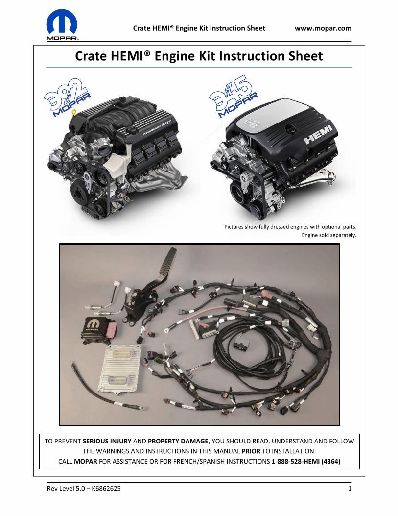
Crate HEMI® Engine Kit Instruction Sheet
Pictures show fully dressed engines with optional parts.
Engine sold separately.
TO PREVENT SERIOUS INJURY AND PROPERTY DAMAGE, YOU SHOULD READ, UNDERSTAND AND FOLLOW
THE WARNINGS AND INSTRUCTIONS IN THIS MANUAL PRIOR TO INSTALLATION.
CALL MOPAR FOR ASSISTANCE OR FOR FRENCH/SPANISH INSTRUCTIONS 1-888-528-HEMI (4364)
Crate HEMI® Engine Kit Instruction Sheet www.mopar.com
Rev Level 5.0 – K6862625 2
Contents Included Parts List ......................................................................................................................................... 2
Drivetrain Requirements ............................................................................................................................... 3
Additional Parts ............................................................................................................................................. 3
Important Safety & Emissions Information ................................................................................................... 4
Component Instructions & Guidelines ........................................................................................................... 6
Engine Connections ..................................................................................................................................... 10
Break-In/Maintenance ................................................................................................................................ 25
Troubleshooting .......................................................................................................................................... 29
Included Parts List
Part Description 5.7L Part Number 6.4L Part Number Service Parts
Quantity
PACKAGE 77072455AB 77072454AB
Accelerator Pedal 04861714AF 04861714AF Y 1
Engine Wiring Harness Kit 77072460 77072457 Y 1
Ground jumper 68060322AE 68060322AE Y 1
O2 Sensor 05149180AA 05149180AA Y 1
O2 Sensor 05149171AA 05149171AA Y 1
PCM P5160105 P5160104 Y 1
Charge Air Temp. Sensor 05149279AC 05149279AC Y 1
NOTE: Revision level (suffix) of part numbers are subject to change.
Engine sold separately:
5.7L Crate HEMI® engine part number: 68303088AA
6.4L Crate HEMI® engine part number: 68303090AA
This kit and instruction sheet is designed for 2015 model year engines part numbers listed above.
Not compatible with 5.7L & 6.4L engines from 2012 and older.
Not compatible with 5.7L & 6.4L engines from RAM truck.
Crankshaft target ring must be part number 04893290AA, a valley width of 6.306 mm measured at the
outer diameter (OD). The crankshaft position sensor part number is 68140678AB.
Crate HEMI® Engine Kit Instruction Sheet www.mopar.com
Rev Level 5.0 – K6862625 3
Drivetrain Requirements Axle Drive Ratio
The recommended axle drive ratio should be 2.61:1 to 3.90:1 to obtain optimal vehicle performance and
fuel economy. A Limited Slip Differential (LSD) or Open differential is recommended for best drivability.
Tire Size
The recommended rear tire size is 28 to 29.5 inches in overall diameter.
Fuel
The fuel grade required for both 5.7L and 6.4L engines is premium (91 octane or greater). The fuel
pressure is a constant 58.5 PSI with the engine running. Fuel pump flow requirements: Minimum 222
Lbs/Hr @ 58.5 PSI (+/- 5 PSI).
Additional Parts Some additional parts may be needed that are not supplied in this kit to complete the powertrain. Each
application is unique and all possibilities and configurations may not be covered in this instruction sheet.
These parts can to be ordered separately through your local Chrysler Dealer or an aftermarket supplier.
Front End Accessory Drive (FEAD) Kit
There is multiple options available for the crate engine FEAD kits. Both crate engines kits come
assembled with a car front engine covers. A FEAD kit is necessary to operate engine, the basic FEAD kit
is part number 77072445.
Engine Mounts
Engine mounts to be fabricated or purchased from an aftermarket source to fit the specific application.
The engine side aluminum mounting brackets that are included on the engine are from a 2016 Dodge
Challenger. It is recommended that the engine mounts incorporate production style engine dampers to
allow for engine vibrations. Engine is installed at a 2° angle (rear down) on a 2016 Dodge Challenger.
Oil Pan
The oil pan supplied with the crate engine is a front sump oil pan design from a 2016 Dodge Challenger.
Some applications may require a rear sump oil pan. The kit part number for a rear sump oil pan is
77072450AB.
Transmission
The flywheel and clutch or flex plate and torque converter combinations needed may be unique to the
application. A flywheel and clutch assembly from a 2016 Dodge Challenger will be included with all crate
engines, please utilize the correct combination of parts for the desired drivetrain selected.
Starter
Ensure the correct starter is selected for your transmission and flex plate or flywheel combination. A
starter nose spacer may be required for the starter motor to properly engage and spin the engine.
Crate HEMI® Engine Kit Instruction Sheet www.mopar.com
Rev Level 5.0 – K6862625 4
Important Safety & Emissions Information
To prevent SERIOUS INJURY or DEATH:
ALWAYS wear eye protection and appropriate protective clothing. You may be exposed to flammable, corrosive and hazardous liquids and materials when installing an engine.
ALWAYS secure the vehicle with the parking break or wheel chock before working on a vehicle.
If you jack the vehicle, securely support the vehicle using jack stands before working under the vehicle.
Make sure you or the installer has the appropriate skills and the tool required to safely install the engine.
If you do not understand the instructions, call MOPAR for assistance at 1-888-528-HEMI (4364).
NEVER modify wiring in the accelerator pedal system.
DO NOT connect battery until all connections are made.
DO NOT start or run an engine in a closed garage or in confined area. Exhaust gases contain Carbon
Monoxide (CO), which is odorless and colorless. Carbon Monoxide is poisonous and can cause serious
injury or death when inhaled.
Follow the precautions below to prevent Carbon Monoxide poisoning:
DO NOT inhale exhaust gases.
NEVER run the engine in a closed area, such as a garage, and never sit in a parked vehicle with
the engine running for an extended period.
EMISSIONS STATEMENT
Intended Use:
CRATE HEMI ENGINES ARE DESIGNED FOR INSTALLATION IN
1. ANY MOTOR VEHICLE MANUFACTURED PRIOR TO MODEL YEAR 1976, AND
2. IN ANY VEHICLE THAT LACKS FEATURES CUSTOMARILY ASSOCIATED WITH SAFE AND PRACTICAL
HIGHWAY USE THAT IS OPERATED NOT ON A STREET OR HIGHWAY.
IT MAY BE A VIOLATION OF FEDERAL LAW SUBJECT TO CIVIL PENALTY TO INSTALL A CRATE HEMI ENGINE
IN ANY MOTOR VEHICLE DESIGNED FOR TRANSPORT ON A STREET OR HIGHWAY THAT WAS
MANUFACTURED IN MODEL YEAR 1976 AND LATER.

Crate HEMI® Engine Kit Instruction Sheet www.mopar.com
Rev Level 5.0 – K6862625 5
Operation and Use Limitations:
Federal and California law prohibit tampering with emissions control equipment or components
required to be equipped on Motor Vehicles. This means that persons may not remove or render
inoperative any device or element of design that impairs the emissions of such Motor Vehicles.
Violators of this prohibition may be subject to civil penalty.
Crate HEMI kits may not be used in place of a regulated or certified nonroad engine (such as in
marine applications).
Installation of a Crate Hemi engine in violation of these Instructions will void any applicable
MOPAR warranty.
5.7L & 6.4L engines from 2013-2016 Challenger/Charger/300 may be comparable to a Crate
Hemi Engine when installed in appropriate vehicles as referenced above along with the
appropriate Crate Hemi Kit.
Mopar Performance customers are responsible for complying with applicable federal state and local
environmental laws and regulations. Many Mopar Performance parts and components are designed to
be equipped in vehicles that are operated not on streets or highways (such as vehicles intended for
competition or off-road use). Motor Vehicles designed for transport on streets or highways and
equipped with such parts may cause such Motor Vehicles to be out of compliance with applicable
emissions standards. It may be a violation of federal and state law to operate such Motor Vehicles
equipped with such parts, except where vehicles equipped with such parts are operated not on streets
or highways and where such vehicles lack features customarily associated with safe and practical
highway use.
If you install such parts on a Motor Vehicle, and your Motor Vehicle fails a required state or local
inspection and maintenance (I/M) emissions test, including any test required to maintain or renew your
Motor Vehicle’s registration, or if your Motor Vehicle is subject to an emissions recall, in either case FCA
US LLC may not be required to repair your Motor Vehicle under the emissions warranty, and you may be
required to remove those parts and replace them with other parts at your own expense in order to
obtain repairs necessary to pass the I/M emissions test or to ensure your Motor Vehicle is compliant
with applicable emissions standards after the recall repair.
Those parts marked in this catalogue with a superscript 1 before the part number and appropriately
marked on their packaging may legally be used on a vehicle that is not operated on streets or highways
and that lacks features customarily associated with safe and practical highway use.
Limited Warranty:
Federal law requires emissions parts on new Motor Vehicles and engines to be warranted for at least
two years or 24,000 miles, whichever comes first.
Crate HEMI® Engine Kit Instruction Sheet www.mopar.com
Rev Level 5.0 – K6862625 6
Component Instructions & Guidelines
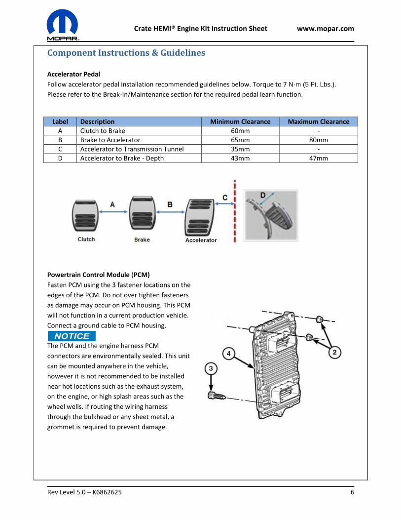
Accelerator Pedal
Follow accelerator pedal installation recommended guidelines below. Torque to 7 N·m (5 Ft. Lbs.).
Please refer to the Break-In/Maintenance section for the required pedal learn function.
Label Description Minimum Clearance Maximum Clearance
A Clutch to Brake 60mm -
B Brake to Accelerator 65mm 80mm
C Accelerator to Transmission Tunnel 35mm -
D Accelerator to Brake - Depth 43mm 47mm
Powertrain Control Module (PCM)
Fasten PCM using the 3 fastener locations on the
edges of the PCM. Do not over tighten fasteners
as damage may occur on PCM housing. This PCM
will not function in a current production vehicle.
Connect a ground cable to PCM housing.
The PCM and the engine harness PCM
connectors are environmentally sealed. This unit
can be mounted anywhere in the vehicle,
however it is not recommended to be installed
near hot locations such as the exhaust system,
on the engine, or high splash areas such as the
wheel wells. If routing the wiring harness
through the bulkhead or any sheet metal, a
grommet is required to prevent damage.
Crate HEMI® Engine Kit Instruction Sheet www.mopar.com
Rev Level 5.0 – K6862625 7
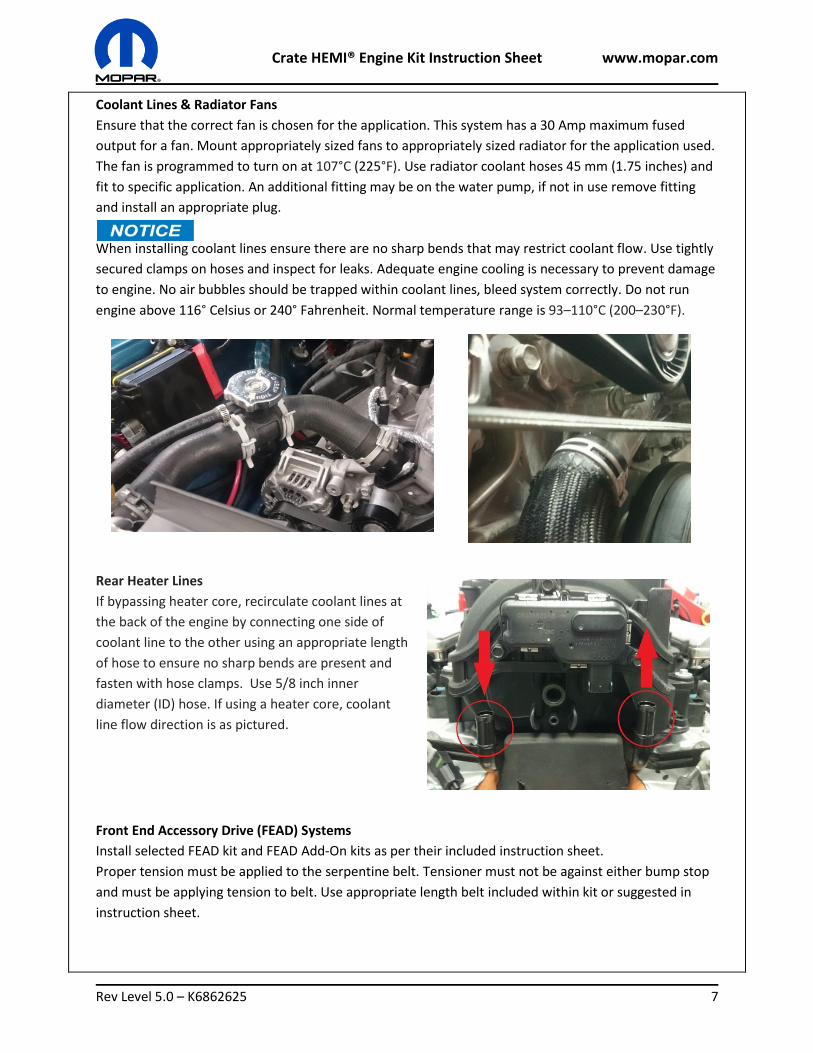
Coolant Lines & Radiator Fans
Ensure that the correct fan is chosen for the application. This system has a 30 Amp maximum fused
output for a fan. Mount appropriately sized fans to appropriately sized radiator for the application used.
The fan is programmed to turn on at 107°C (225°F). Use radiator coolant hoses 45 mm (1.75 inches) and
fit to specific application. An additional fitting may be on the water pump, if not in use remove fitting
and install an appropriate plug.
When installing coolant lines ensure there are no sharp bends that may restrict coolant flow. Use tightly
secured clamps on hoses and inspect for leaks. Adequate engine cooling is necessary to prevent damage
to engine. No air bubbles should be trapped within coolant lines, bleed system correctly. Do not run
engine above 116° Celsius or 240° Fahrenheit. Normal temperature range is 93–110°C (200–230°F).
Rear Heater Lines
If bypassing heater core, recirculate coolant lines at
the back of the engine by connecting one side of
coolant line to the other using an appropriate length
of hose to ensure no sharp bends are present and
fasten with hose clamps. Use 5/8 inch inner
diameter (ID) hose. If using a heater core, coolant
line flow direction is as pictured.
Front End Accessory Drive (FEAD) Systems
Install selected FEAD kit and FEAD Add-On kits as per their included instruction sheet.
Proper tension must be applied to the serpentine belt. Tensioner must not be against either bump stop
and must be applying tension to belt. Use appropriate length belt included within kit or suggested in
instruction sheet.
Crate HEMI® Engine Kit Instruction Sheet www.mopar.com
Rev Level 5.0 – K6862625 8
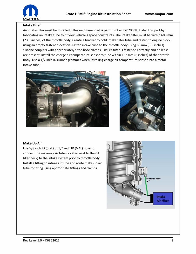
Intake Filter
An intake filter must be installed, filter recommended is part number 77070038. Install this part by
fabricating an intake tube to fit your vehicle’s space constraints. The intake filter must be within 600 mm
(23.6 inches) of the throttle body. Create a bracket to hold intake filter tube and fasten to engine block
using an empty fastener location. Fasten intake tube to the throttle body using 89 mm (3.5 inches)
silicone couplers with appropriately sized hose clamps. Ensure filter is fastened correctly and no leaks
are present. Install the charge air temperature sensor to tube within 152 mm (6 inches) of the throttle
body. Use a 1/2 inch ID rubber grommet when installing charge air temperature sensor into a metal
intake tube.
Make-Up Air
Use 5/8 inch ID (5.7L) or 3/4 inch ID (6.4L) hose to
connect the make-up air tube (located next to the oil
filler neck) to the intake system prior to throttle body.
Install a fitting to intake air tube and route make-up air
tube to fitting using appropriate fittings and clamps.
Crate HEMI® Engine Kit Instruction Sheet www.mopar.com
Rev Level 5.0 – K6862625 9
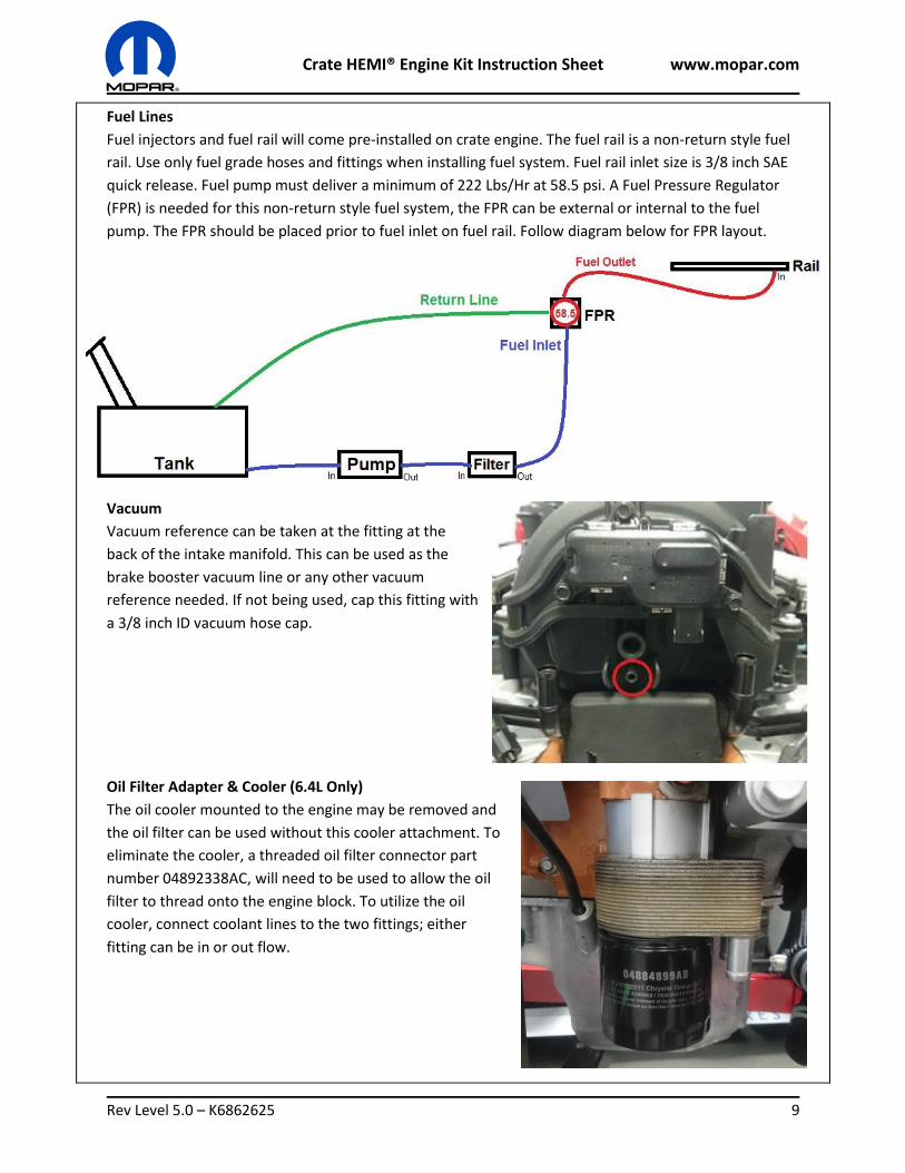
Fuel Lines
Fuel injectors and fuel rail will come pre-installed on crate engine. The fuel rail is a non-return style fuel
rail. Use only fuel grade hoses and fittings when installing fuel system. Fuel rail inlet size is 3/8 inch SAE
quick release. Fuel pump must deliver a minimum of 222 Lbs/Hr at 58.5 psi. A Fuel Pressure Regulator
(FPR) is needed for this non-return style fuel system, the FPR can be external or internal to the fuel
pump. The FPR should be placed prior to fuel inlet on fuel rail. Follow diagram below for FPR layout.
Vacuum
Vacuum reference can be taken at the fitting at the
back of the intake manifold. This can be used as the
brake booster vacuum line or any other vacuum
reference needed. If not being used, cap this fitting with
a 3/8 inch ID vacuum hose cap.
Oil Filter Adapter & Cooler (6.4L Only)
The oil cooler mounted to the engine may be removed and
the oil filter can be used without this cooler attachment. To
eliminate the cooler, a threaded oil filter connector part
number 04892338AC, will need to be used to allow the oil
filter to thread onto the engine block. To utilize the oil
cooler, connect coolant lines to the two fittings; either
fitting can be in or out flow.
Crate HEMI® Engine Kit Instruction Sheet www.mopar.com
Rev Level 5.0 – K6862625 10
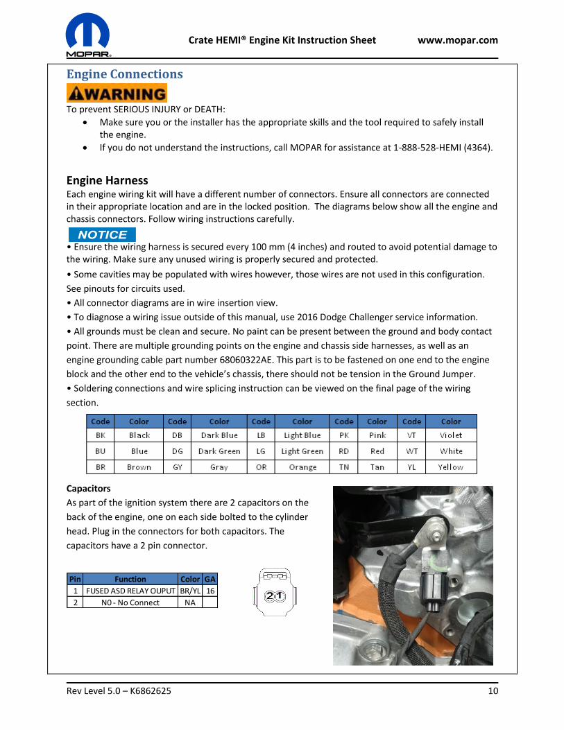
Pin Function Color GA
1 FUSED ASD RELAY OUPUT BR/YL 16
2 N0 - No Connect NA
Engine Connections
To prevent SERIOUS INJURY or DEATH:
Make sure you or the installer has the appropriate skills and the tool required to safely install the engine.
If you do not understand the instructions, call MOPAR for assistance at 1-888-528-HEMI (4364).
Engine Harness
Each engine wiring kit will have a different number of connectors. Ensure all connectors are connected in their appropriate location and are in the locked position. The diagrams below show all the engine and chassis connectors. Follow wiring instructions carefully.
• Ensure the wiring harness is secured every 100 mm (4 inches) and routed to avoid potential damage to the wiring. Make sure any unused wiring is properly secured and protected.
• Some cavities may be populated with wires however, those wires are not used in this configuration.
See pinouts for circuits used.
• All connector diagrams are in wire insertion view.
• To diagnose a wiring issue outside of this manual, use 2016 Dodge Challenger service information.
• All grounds must be clean and secure. No paint can be present between the ground and body contact
point. There are multiple grounding points on the engine and chassis side harnesses, as well as an
engine grounding cable part number 68060322AE. This part is to be fastened on one end to the engine
block and the other end to the vehicle’s chassis, there should not be tension in the Ground Jumper.
• Soldering connections and wire splicing instruction can be viewed on the final page of the wiring
section.
Capacitors
As part of the ignition system there are 2 capacitors on the
back of the engine, one on each side bolted to the cylinder
head. Plug in the connectors for both capacitors. The
capacitors have a 2 pin connector.
Crate HEMI® Engine Kit Instruction Sheet www.mopar.com
Rev Level 5.0 – K6862625 11
Pin Function Color GA
1 COIL CONTROL 1 DB/DG 16
2 FUSED ASD RELAY OUTPUT BR/YL 16
3 NO CONNECT NA
1 COIL CONTROL 2 DB/TN 16
2 FUSED ASD RELAY OUTPUT BR/YL 16
3 NO CONNECT NA
1 COIL CONTROL 3 DB/OR 16
2 FUSED ASD RELAY OUTPUT BR/YL 16
3 NO CONNECT NA
1 COIL CONTROL 4 DB/GY 16
2 FUSED ASD RELAY OUTPUT BR/YL 16
3 NO CONNECT NA
1 COIL CONTROL 5 DB/YL 16
2 FUSED ASD RELAY OUTPUT BR/YL 16
3 NO CONNECT NA
1 COIL CONTROL 6 DB/OR 16
2 FUSED ASD RELAY OUTPUT BR/YL 16
3 NO CONNECT NA
1 COIL CONTROL 7 BR 16
2 FUSED ASD RELAY OUTPUT BR/YL 16
3 NO CONNECT NA
1 COIL CONTROL 8 DB/YL 16
2 FUSED ASD RELAY OUTPUT BR/YL 16
3 NO CONNECT NA
Coilpack 7
Coilpack 8
Coilpack 4
Coilpack 3
Coilpack 2
Coilpack 1
Coilpack 5
Coilpack 6
Pin Function Color GA
1 INJECTOR CONTROL 1 BR/YE 20
2 ASD CONTROL OUTPUT BR/WT 16
1 INJECTOR CONTROL 2 BR/DB 20
2 ASD CONTROL OUTPUT BR/WT 16
1 INJECTOR CONTROL 3 BR/BU 20
2 ASD CONTROL OUTPUT BR/WT 16
1 INJECTOR CONTROL 4 BR/BG 20
2 ASD CONTROL OUTPUT BR/WT 16
1 INJECTOR CONTROL 5 BR/OR 20
2 ASD CONTROL OUTPUT BR/WT 16
1 INJECTOR CONTROL 6 BR/VT 20
2 ASD CONTROL OUTPUT BR/WT 16
1 INJECTOR CONTROL 7 BR/YL 20
2 ASD CONTROL OUTPUT BR/WT 16
1 INJECTOR CONTROL 8 BR/BU 20
2 ASD CONTROL OUTPUT BR/WT 16
Fuel Injector 2
Fuel Injector 1
Fuel Injector 8
Fuel Injector 7
Fuel Injector 6
Fuel Injector 5
Fuel Injector 4
Fuel Injector 3
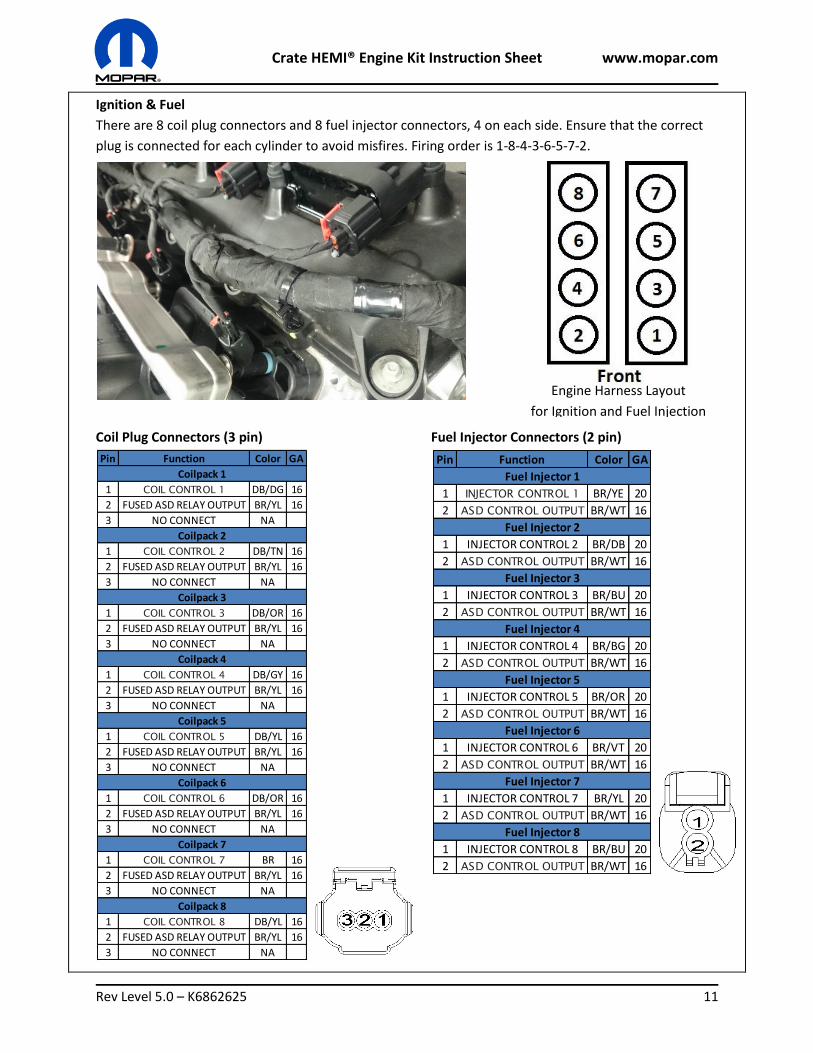
Ignition & Fuel
There are 8 coil plug connectors and 8 fuel injector connectors, 4 on each side. Ensure that the correct
plug is connected for each cylinder to avoid misfires. Firing order is 1-8-4-3-6-5-7-2.
Coil Plug Connectors (3 pin) Fuel Injector Connectors (2 pin)
Engine Harness Layout
for Ignition and Fuel Injection
Crate HEMI® Engine Kit Instruction Sheet www.mopar.com
Rev Level 5.0 – K6862625 12
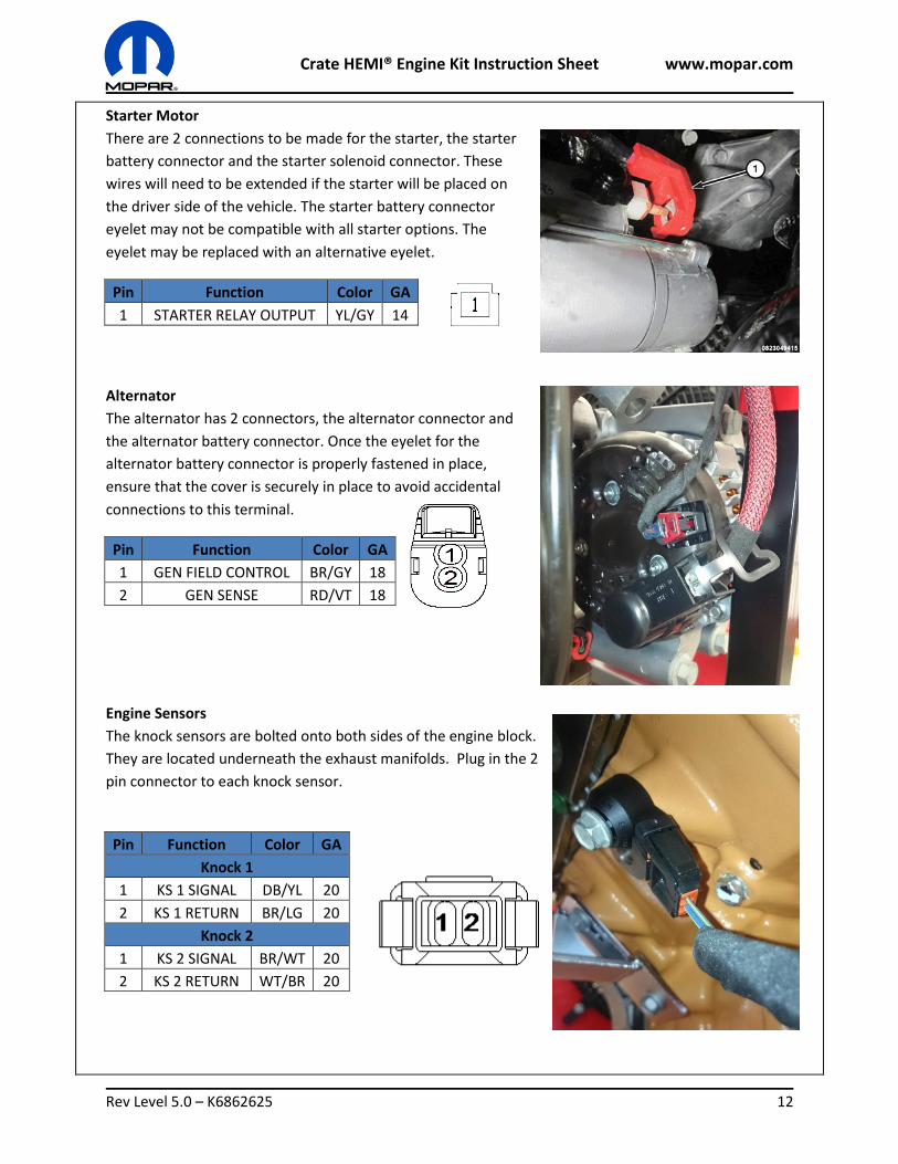
Starter Motor
There are 2 connections to be made for the starter, the starter
battery connector and the starter solenoid connector. These
wires will need to be extended if the starter will be placed on
the driver side of the vehicle. The starter battery connector
eyelet may not be compatible with all starter options. The
eyelet may be replaced with an alternative eyelet.
Pin Function Color GA
1 STARTER RELAY OUTPUT YL/GY 14
Alternator
The alternator has 2 connectors, the alternator connector and
the alternator battery connector. Once the eyelet for the
alternator battery connector is properly fastened in place,
ensure that the cover is securely in place to avoid accidental
connections to this terminal.
Pin Function Color GA
1 GEN FIELD CONTROL BR/GY 18
2 GEN SENSE RD/VT 18
Engine Sensors
The knock sensors are bolted onto both sides of the engine block.
They are located underneath the exhaust manifolds. Plug in the 2
pin connector to each knock sensor.
Pin Function Color GA
Knock 1
1 KS 1 SIGNAL DB/YL 20
2 KS 1 RETURN BR/LG 20
Knock 2
1 KS 2 SIGNAL BR/WT 20
2 KS 2 RETURN WT/BR 20
Crate HEMI® Engine Kit Instruction Sheet www.mopar.com
Rev Level 5.0 – K6862625 13
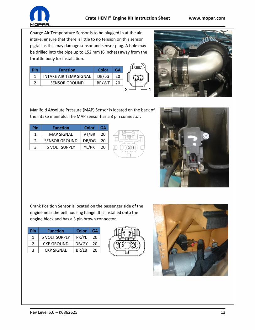
Charge Air Temperature Sensor is to be plugged in at the air
intake, ensure that there is little to no tension on this sensor
pigtail as this may damage sensor and sensor plug. A hole may
be drilled into the pipe up to 152 mm (6 inches) away from the
throttle body for installation.
Pin Function Color GA
1 INTAKE AIR TEMP SIGNAL DB/LG 20
2 SENSOR GROUND BR/WT 20
Manifold Absolute Pressure (MAP) Sensor is located on the back of
the intake manifold. The MAP sensor has a 3 pin connector.
Pin Function Color GA
1 MAP SIGNAL VT/BR 20
2 SENSOR GROUND DB/DG 20
3 5 VOLT SUPPLY YL/PK 20
Crank Position Sensor is located on the passenger side of the
engine near the bell housing flange. It is installed onto the
engine block and has a 3 pin brown connector.
Pin Function Color GA
1 5 VOLT SUPPLY PK/YL 20
2 CKP GROUND DB/GY 20
3 CKP SIGNAL BR/LB 20
Crate HEMI® Engine Kit Instruction Sheet www.mopar.com
Rev Level 5.0 – K6862625 14
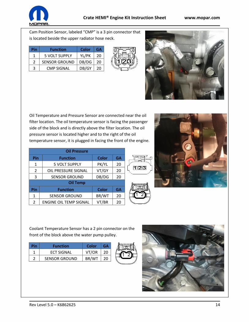
Cam Position Sensor, labeled “CMP” is a 3 pin connector that
is located beside the upper radiator hose neck.
Pin Function Color GA
1 5 VOLT SUPPLY YL/PK 20
2 SENSOR GROUND DB/DG 20
3 CMP SIGNAL DB/GY 20
Oil Temperature and Pressure Sensor are connected near the oil
filter location. The oil temperature sensor is facing the passenger
side of the block and is directly above the filter location. The oil
pressure sensor is located higher and to the right of the oil
temperature sensor, it is plugged in facing the front of the engine.
Oil Pressure
Pin Function Color GA
1 5 VOLT SUPPLY PK/YL 20
2 OIL PRESSURE SIGNAL VT/GY 20
3 SENSOR GROUND DB/DG 20
Oil Temp
Pin Function Color GA
1 SENSOR GROUND BR/WT 20
2 ENGINE OIL TEMP SIGNAL VT/BR 20
Coolant Temperature Sensor has a 2 pin connector on the
front of the block above the water pump pulley.
Pin Function Color GA
1 ECT SIGNAL VT/OR 20
2 SENSOR GROUND BR/WT 20
Crate HEMI® Engine Kit Instruction Sheet www.mopar.com
Rev Level 5.0 – K6862625 15
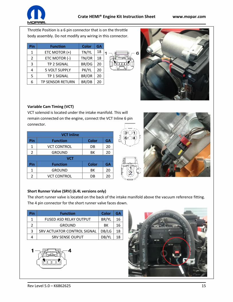
Throttle Position is a 6 pin connector that is on the throttle
body assembly. Do not modify any wiring in this connector.
Pin Function Color GA
1 ETC MOTOR (+) TN/YL 18
2 ETC MOTOR (-) TN/OR 18
3 TP 2 SIGNAL BR/DG 20
4 5 VOLT SUPPLY PK/YL 20
5 TP 1 SIGNAL BR/OR 20
6 TP SENSOR RETURN BR/DB 20
Variable Cam Timing (VCT)
VCT solenoid is located under the intake manifold. This will
remain connected on the engine, connect the VCT Inline 6 pin
connector.
VCT Inline
Pin Function Color GA
1 VCT CONTROL DB 20
2 GROUND BK 20
VCT
Pin Function Color GA
1 GROUND BK 20
2 VCT CONTROL DB 20
Short Runner Valve (SRV) (6.4L versions only)
The short runner valve is located on the back of the intake manifold above the vacuum reference fitting.
The 4 pin connector for the short runner valve faces down.
Pin Function Color GA
1 FUSED ASD RELAY OUTPUT BR/YL 16
2 GROUND BK 16
3 SRV ACTUATOR CONTROL SIGNAL DB/LG 18
4 SRV SENSE OUPUT DB/YL 18
Crate HEMI® Engine Kit Instruction Sheet www.mopar.com
Rev Level 5.0 – K6862625 16
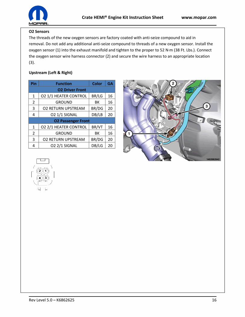
O2 Sensors
The threads of the new oxygen sensors are factory coated with anti-seize compound to aid in
removal. Do not add any additional anti-seize compound to threads of a new oxygen sensor. Install the
oxygen sensor (1) into the exhaust manifold and tighten to the proper to 52 N∙m (38 Ft. Lbs.). Connect
the oxygen sensor wire harness connector (2) and secure the wire harness to an appropriate location
(3).
Upstream (Left & Right)
Pin Function Color GA
O2 Driver Front
1 O2 1/1 HEATER CONTROL BR/LG 16
2 GROUND BK 16
3 O2 RETURN UPSTREAM BR/DG 20
4 O2 1/1 SIGNAL DB/LB 20
O2 Passenger Front
1 O2 2/1 HEATER CONTROL BR/VT 16
2 GROUND BK 16
3 O2 RETURN UPSTREAM BR/DG 20
4 O2 2/1 SIGNAL DB/LG 20
Crate HEMI® Engine Kit Instruction Sheet www.mopar.com
Rev Level 5.0 – K6862625 17
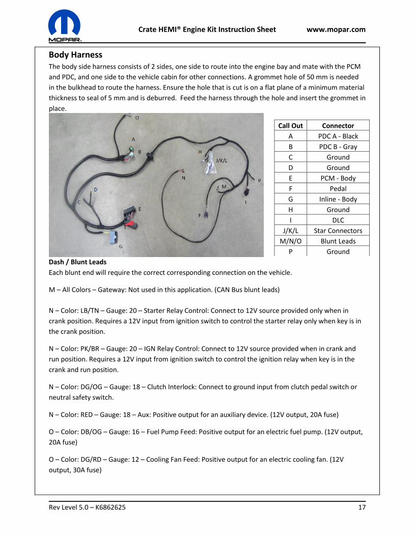
Body Harness
The body side harness consists of 2 sides, one side to route into the engine bay and mate with the PCM
and PDC, and one side to the vehicle cabin for other connections. A grommet hole of 50 mm is needed
in the bulkhead to route the harness. Ensure the hole that is cut is on a flat plane of a minimum material
thickness to seal of 5 mm and is deburred. Feed the harness through the hole and insert the grommet in
place.
Dash / Blunt Leads
Each blunt end will require the correct corresponding connection on the vehicle.
M – All Colors – Gateway: Not used in this application. (CAN Bus blunt leads)
N – Color: LB/TN – Gauge: 20 – Starter Relay Control: Connect to 12V source provided only when in
crank position. Requires a 12V input from ignition switch to control the starter relay only when key is in
the crank position.
N – Color: PK/BR – Gauge: 20 – IGN Relay Control: Connect to 12V source provided when in crank and
run position. Requires a 12V input from ignition switch to control the ignition relay when key is in the
crank and run position.
N – Color: DG/OG – Gauge: 18 – Clutch Interlock: Connect to ground input from clutch pedal switch or
neutral safety switch.
N – Color: RED – Gauge: 18 – Aux: Positive output for an auxiliary device. (12V output, 20A fuse)
O – Color: DB/OG – Gauge: 16 – Fuel Pump Feed: Positive output for an electric fuel pump. (12V output,
20A fuse)
O – Color: DG/RD – Gauge: 12 – Cooling Fan Feed: Positive output for an electric cooling fan. (12V
output, 30A fuse)
Call Out Connector
A PDC A - Black
B PDC B - Gray
C Ground
D Ground
E PCM - Body
F Pedal
G Inline - Body
H Ground
I DLC
J/K/L Star Connectors
M/N/O Blunt Leads
P Ground
Crate HEMI® Engine Kit Instruction Sheet www.mopar.com
Rev Level 5.0 – K6862625 18
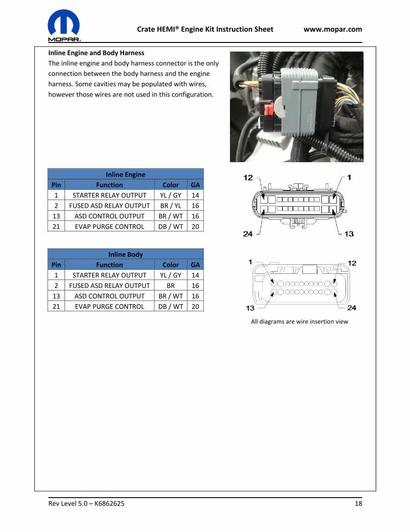
Inline Engine and Body Harness
The inline engine and body harness connector is the only
connection between the body harness and the engine
harness. Some cavities may be populated with wires,
however those wires are not used in this configuration.
Inline Engine
Pin Function Color GA
1 STARTER RELAY OUTPUT YL / GY 14
2 FUSED ASD RELAY OUTPUT BR / YL 16
13 ASD CONTROL OUTPUT BR / WT 16
21 EVAP PURGE CONTROL DB / WT 20
Inline Body
Pin Function Color GA
1 STARTER RELAY OUTPUT YL / GY 14
2 FUSED ASD RELAY OUTPUT BR 16
13 ASD CONTROL OUTPUT BR / WT 16
21 EVAP PURGE CONTROL DB / WT 20
All diagrams are wire insertion view
Crate HEMI® Engine Kit Instruction Sheet www.mopar.com
Rev Level 5.0 – K6862625 19
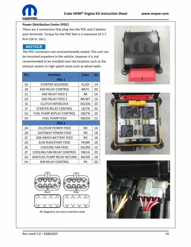
Power Distribution Center (PDC)
There are 2 connectors that plug into the PDC and 2 battery
post terminals. Torque for the PDC feet is a maximum of 2.7
N·m (24 In. Lbs.).
The PDC connectors are environmentally sealed. This unit can
be mounted anywhere in the vehicle, however it is not
recommended to be installed near hot locations such as the
exhaust system or high splash areas such as wheel wells.
Pin Function Color GA
PDC 1
1A STARTER SOLENOID YL/GY 14
1B ASD RELAY CONTROL BR/YL 20
1C ASD RELAY FEED 1 BR 16
1D ASD RELAY FEED 2 BR/WT 16
1E CLUTCH INTERLOCK DG/OG 20
1F STARTER RELAY CONTROL LB/TN 20
1G FUEL PUMP REPLAY CONTROL DB/TN 20
1H FUEL PUMP FEED DB/OG 12
PDC 2
2A DLC/ECM POWER FEED RD 16
2B GATEWAY POWER FEED RD 18
2C IGN SWICH BATTERY FEED RD 18
2D ECM RUN/START FEED PK/BR 18
2E COOLING FAN FEED DG/RD 12
2F COOLING FAN RELAY CONTROL DB/LG 20
2G IGN/FUEL PUMP RELAY RETURN BK/GR 18
2H IGN RELAY CONTROL PK 20
All diagrams are wire insertion view
Crate HEMI® Engine Kit Instruction Sheet www.mopar.com
Rev Level 5.0 – K6862625 20
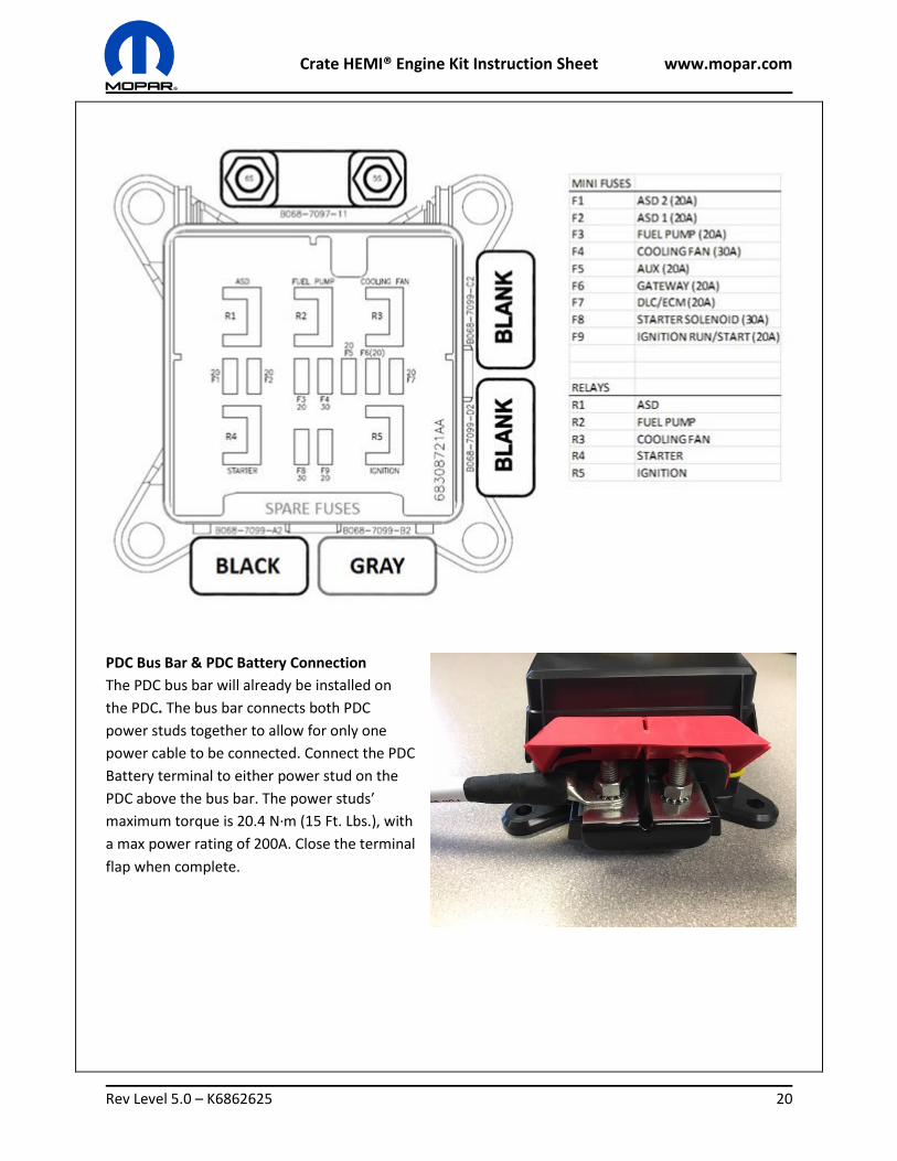
PDC Bus Bar & PDC Battery Connection
The PDC bus bar will already be installed on
the PDC. The bus bar connects both PDC
power studs together to allow for only one
power cable to be connected. Connect the PDC
Battery terminal to either power stud on the
PDC above the bus bar. The power studs’
maximum torque is 20.4 N·m (15 Ft. Lbs.), with
a max power rating of 200A. Close the terminal
flap when complete.
Crate HEMI® Engine Kit Instruction Sheet www.mopar.com
Rev Level 5.0 – K6862625 21
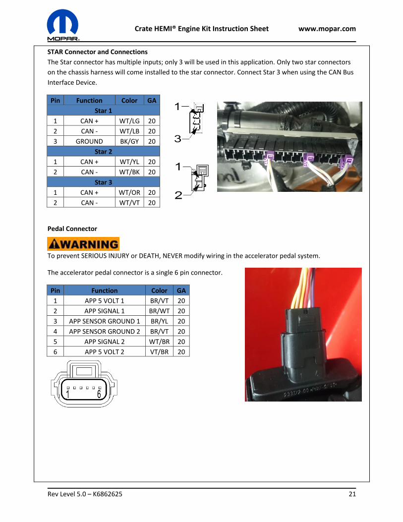
STAR Connector and Connections
The Star connector has multiple inputs; only 3 will be used in this application. Only two star connectors
on the chassis harness will come installed to the star connector. Connect Star 3 when using the CAN Bus
Interface Device.
Pin Function Color GA
Star 1
1 CAN + WT/LG 20
2 CAN - WT/LB 20
3 GROUND BK/GY 20
Star 2
1 CAN + WT/YL 20
2 CAN - WT/BK 20
Star 3
1 CAN + WT/OR 20
2 CAN - WT/VT 20
Pedal Connector
To prevent SERIOUS INJURY or DEATH, NEVER modify wiring in the accelerator pedal system.
The accelerator pedal connector is a single 6 pin connector.
Pin Function Color GA
1 APP 5 VOLT 1 BR/VT 20
2 APP SIGNAL 1 BR/WT 20
3 APP SENSOR GROUND 1 BR/YL 20
4 APP SENSOR GROUND 2 BR/VT 20
5 APP SIGNAL 2 WT/BR 20
6 APP 5 VOLT 2 VT/BR 20
Crate HEMI® Engine Kit Instruction Sheet www.mopar.com
Rev Level 5.0 – K6862625 22
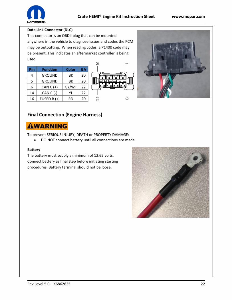
Data Link Connector (DLC)
This connector is an OBDII plug that can be mounted
anywhere in the vehicle to diagnose issues and codes the PCM
may be outputting. When reading codes, a P1400 code may
be present. This indicates an aftermarket controller is being
used.
Pin Function Color GA
4 GROUND BK 20
5 GROUND BK 20
6 CAN C (+) GY/WT 22
14 CAN C (-) YL 22
16 FUSED B (+) RD 20
Final Connection (Engine Harness)
To prevent SERIOUS INJURY, DEATH or PROPERTY DAMAGE:
DO NOT connect battery until all connections are made.
Battery
The battery must supply a minimum of 12.65 volts.
Connect battery as final step before initiating starting
procedures. Battery terminal should not be loose.
Crate HEMI® Engine Kit Instruction Sheet www.mopar.com
Rev Level 5.0 – K6862625 23
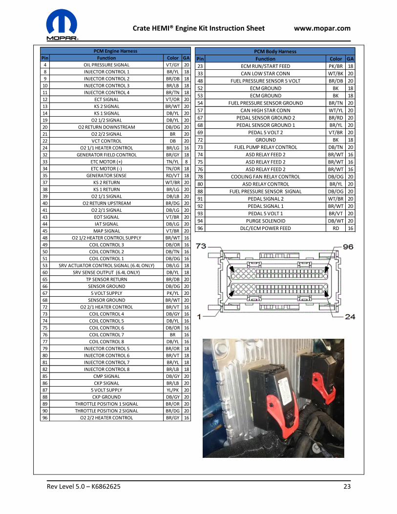
Pin Function Color GA
23 ECM RUN/START FEED PK/BR 18
33 CAN LOW STAR CONN WT/BK 20
48 FUEL PRESSURE SENSOR 5 VOLT BR/DB 20
52 ECM GROUND BK 18
53 ECM GROUND BK 18
54 FUEL PRESSURE SENSOR GROUND BR/TN 20
57 CAN HIGH STAR CONN WT/YL 20
67 PEDAL SENSOR GROUND 2 BR/RD 20
68 PEDAL SENSOR GROUND 1 BR/YL 20
69 PEDAL 5 VOLT 2 VT/BR 20
72 GROUND BK 18
73 FUEL PUMP RELAY CONTROL DB/TN 20
74 ASD RELAY FEED 2 BR/WT 16
75 ASD RELAY FEED 2 BR/WT 16
76 ASD RELAY FEED 2 BR/WT 16
78 COOLING FAN RELAY CONTROL DB/OG 20
80 ASD RELAY CONTROL BR/YL 20
88 FUEL PRESSURE SENSOR SIGNAL DB/OG 20
91 PEDAL SIGNAL 2 WT/BR 20
92 PEDAL SIGNAL 1 BR/WT 20
93 PEDAL 5 VOLT 1 BR/VT 20
94 PURGE SOLENOID DB/WT 20
96 DLC/ECM POWER FEED RD 16
PCM Body HarnessPin Function Color GA
4 OIL PRESSURE SIGNAL VT/GY 20
8 INJECTOR CONTROL 1 BR/YL 18
9 INJECTOR CONTROL 2 BR/DB 18
10 INJECTOR CONTROL 3 BR/LB 18
11 INJECTOR CONTROL 4 BR/TN 18
12 ECT SIGNAL VT/OR 20
13 KS 2 SIGNAL BR/WT 20
14 KS 1 SIGNAL DB/YL 20
19 O2 1/2 SIGNAL DB/YL 20
20 O2 RETURN DOWNSTREAM DB/DG 20
21 O2 2/2 SIGNAL BR 20
22 VCT CONTROL DB 20
24 O2 1/1 HEATER CONTROL BR/LG 16
32 GENERATOR FIELD CONTROL BR/GY 18
33 ETC MOTOR (+) TN/YL 8
34 ETC MOTOR (-) TN/OR 18
35 GENERATOR SENSE RD/VT 18
37 KS 2 RETURN WT/BR 20
38 KS 1 RETURN BR/LG 20
39 O2 1/1 SIGNAL DB/LB 20
40 O2 RETURN UPSTREAM BR/DG 20
41 O2 2/1 SIGNAL DB/LG 20
43 EOT SIGNAL VT/BR 20
44 IAT SIGNAL DB/LG 20
45 MAP SIGNAL VT/BR 20
48 O2 1/2 HEATER CONTROL SUPPLY BR/WT 16
49 COIL CONTROL 3 DB/OR 16
50 COIL CONTROL 2 DB/TN 16
51 COIL CONTROL 1 DB/DG 16
53 SRV ACTUATOR CONTROL SIGNAL (6.4L ONLY) DB/LG 18
60 SRV SENSE OUTPUT (6.4L ONLY) DB/YL 18
65 TP SENSOR RETURN BR/DB 20
66 SENSOR GROUND DB/DG 20
67 5 VOLT SUPPLY PK/YL 20
68 SENSOR GROUND BR/WT 20
72 O2 2/1 HEATER CONTROL BR/VT 16
73 COIL CONTROL 4 DB/GY 16
74 COIL CONTROL 5 DB/YL 16
75 COIL CONTROL 6 DB/OR 16
76 COIL CONTROL 7 BR 16
77 COIL CONTROL 8 DB/YL 16
79 INJECTOR CONTROL 5 BR/OR 18
80 INJECTOR CONTROL 6 BR/VT 18
81 INJECTOR CONTROL 7 BR/YL 18
82 INJECTOR CONTROL 8 BR/LB 18
85 CMP SIGNAL DB/GY 20
86 CKP SIGNAL BR/LB 20
87 5 VOLT SUPPLY YL/PK 20
88 CKP GROUND DB/GY 20
89 THROTTLE POSITION 1 SIGNAL BR/OR 20
90 THROTTLE POSITION 2 SIGNAL BR/DG 20
96 O2 2/2 HEATER CONTROL BR/GY 16
PCM Engine Harness
Crate HEMI® Engine Kit Instruction Sheet www.mopar.com
Rev Level 5.0 – K6862625 24
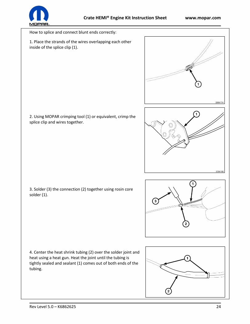
How to splice and connect blunt ends correctly:
1. Place the strands of the wires overlapping each other inside of the splice clip (1).
2. Using MOPAR crimping tool (1) or equivalent, crimp the splice clip and wires together.
3. Solder (3) the connection (2) together using rosin core solder (1).
4. Center the heat shrink tubing (2) over the solder joint and heat using a heat gun. Heat the joint until the tubing is tightly sealed and sealant (1) comes out of both ends of the tubing.
Crate HEMI® Engine Kit Instruction Sheet www.mopar.com
Rev Level 5.0 – K6862625 25
Break-In/Maintenance Follow this procedure below in the correct order and read all content prior to starting your new crate
engine.
Engine Oil
For best performance and maximum protection under all types of operating conditions, the
manufacturer only recommends full synthetic engine oils that meet the American Petroleum Institute
(API) categories of SN.
The engine oil filler cap also shows the recommended engine oil viscosity for the engine. Use synthetic engine oils provided the recommended oil quality requirements are met, and the recommended maintenance intervals for oil and filter changes are followed. Synthetic engine oils which do not have both the engine oil certification mark and the correct SAE viscosity grade number should not be used. The manufacturer strongly recommends against the addition of any additives (other than leak detection dyes) to the engine oil. Engine oil is an engineered product and its performance may be impaired by supplemental additives.
To assure proper engine lubrication, the engine oil must be maintained at the correct level. Check the oil level at regular intervals, such as once a month. The best time to check the engine oil level is about five minutes after a fully warmed engine is shut off. Checking the oil while the vehicle is on level ground will improve the accuracy of the oil level readings. Maintain the oil level in the “SAFE” range. Adding 1.0 quart (.95 liters) of oil when the reading is at the bottom of the “SAFE” range will result in an oil level at the top of the “SAFE” range on these engines.
Overfilling or underfilling will cause oil aeration or loss of oil pressure. This could damage your engine.
Under no circumstances should oil change intervals exceed 6,000 miles (10,000 km) or six months, whichever occurs first.
Do not use chemical flushes in your engine oil as the chemicals can damage your engine
Coolant
Use only MOPAR Antifreeze/Engine Coolant (OAT coolant conforming to MS.90032) 10 Year/150,000
Mile Formula or equivalent in the engine’s cooling system.
Mixing of engine coolant (antifreeze) other than specified Organic Additive Technology (OAT) engine coolant (antifreeze) may result in engine damage and may decrease corrosion protection. OAT engine coolant is different and should not be mixed with Hybrid Organic Additive Technology (HOAT) engine coolant (antifreeze) or any “globally compatible” coolant (antifreeze). If a non-OAT engine coolant (antifreeze) is introduced into the cooling system in an emergency, the cooling system will need to be drained, flushed, and refilled with fresh OAT coolant (conforming to MS.90032) by an authorized dealer as soon as possible.
5.7L SAE 5W-20, Synthetic API Certified FCA Material Standard MS-6395 6.6 Liters 7 Quarts
6.4L SAE 0W-40, Synthetic API Certified FCA Material Standard MS-12633 6.6 Liters 7 Quarts
Crate HEMI® Engine Kit Instruction Sheet www.mopar.com
Rev Level 5.0 – K6862625 26
Do not use water alone or alcohol-based engine coolant (antifreeze) products. Do not use additional rust inhibitors or antirust products, as they may not be compatible with the engine coolant.
This engine has not been designed for use with propylene glycol-based engine coolant (antifreeze). Use of propylene glycol-based engine coolant (antifreeze) is not recommended.
Pedal Learn Visit a MOPAR dealer to perform the pedal learn function below:
1. Connect a battery charger to the vehicle. 2. Cycle ignition to RUN. 3. Connect the scan tool (wiTECH 2.0). 4. Enter VIN as “11111111111111111”. 5. Select “2015” and “LA” (Challenger) as vehicle from drop down menus. 6. Select “PCM.” 7. Select “Misc Functions.” 8. Select “Learn ETC.” 9. Follow on-screen instructions. 10. Cycle ignition key after the successful routine completion.
Oil Prime
Ensure proper lubrication within the head of the engine and throughout the valve train. This can be
done by removing the head covers. Prior to starting the engine, prime the oil system using a pre-lube
engine oiler tank. Fill oil filter with oil and install, then remove oil pressure switch and fit the correct
adapter for your pre-lube engine oiler. Ensure there is oil pressure prior to turning engine over. Check oil
level and for oil leaks from filter, oil coolers, oil filter adapters and fittings.
Fuel Prime
Turn ignition key to “on” position and leave it on the on position for 3-5 seconds, listen for fuel pump
priming. Turn ignition key to “off” position and wait approximately 3 seconds. Repeat this process 5
times. The fuel system should be pressurized now.
To prevent SERIOUS INJURY, DEATH or PROPERTY DAMAGE:
Before starting the engine:
Ensure transmission is in the neural position
Secure vehicle with the parking brake or wheel chuck
Start & Check
Once all other procedures above are complete turn engine over using the ignition key. Turn ignition key
to “on” position, listen for fuel pump priming, turn ignition key to “start” position and hold until motor
start or for 5 seconds maximum. Return key to “on” position and repeat a maximum of 5 times to start
engine. Once engine has started, listen for unusual noises such as engine knock or engine misfires. FEAD
drive belts may be noisy at first if tension is not correct or engine is very cold.
Crate HEMI® Engine Kit Instruction Sheet www.mopar.com
Rev Level 5.0 – K6862625 27
Warm Up
Once started the engine will be cold and will idle at a high RPM. Do not depress the accelerator during
warm-up stage. The RPM should decrease gradually as temperature increases. The idle RPM will level
out and the engine should be running at approximately 200–230°F (93–110°C). Once the engine has
reached operating temperature, follow Break-In procedure below.
Break-In
The following tips will be helpful in obtaining optimum performance and maximum durability for your
new crate engine.
Despite modern technology and World Class manufacturing methods, the moving parts of the engine must still wear in with each other. This wearing in occurs mainly during the first 500 miles (805 km) and continues through the first oil change interval. It is recommended for the operator to observe the following driving behaviors during the new engine break-in period:
0 to 100 miles (0 to 161 km):
Do not allow the engine to operate at idle for an extended period of time. Depress the accelerator pedal slowly and not more than halfway to avoid rapid acceleration. Drive with the engine speed less than 3,500 RPM.
100 to 300 miles (161 to 483 km):
Depress the accelerator pedal slowly and not more than halfway to avoid rapid acceleration in lower gears (1st to 3rd gears).
Drive with the engine speed less than 5,000 RPM.
300 to 500 miles (483 to 805 km):
Exercise the full engine rpm range, shifting manually (paddles or gear shift) at higher rpms when possible.
Do not perform sustained operation with the accelerator pedal at wide open throttle.
500 to 1000 miles (805 to 1610 km):
Exercise the full engine rpm range, shifting manually at higher rpms when possible. Do not perform sustained operation with the accelerator pedal at wide open throttle.
For the first 1500 miles (2414 km):
Do not participate in track events, sport driving schools, or similar activities during the first 1500 mi (2414 km).
NOTE: Check engine oil with every refueling and add if necessary. Oil and fuel consumption may be higher through the first oil change interval. Running the engine with an oil level below the add mark can cause severe engine damage.
Crate HEMI® Engine Kit Instruction Sheet www.mopar.com
Rev Level 5.0 – K6862625 28
Oil Change
The engine oil filter should be replaced with a new filter at every engine oil change. This manufacturer's
engines have a full-flow type oil filter. Use a filter of this type for replacement. The quality of
replacement filters varies considerably. Only high quality filters should be used to assure most efficient
service. MOPAR engine oil filters are a high quality oil filter and are recommended.
Care should be taken in disposing of used engine oil and oil filters from your vehicle. Used oil and oil
filters, indiscriminately discarded, can present a problem to the environment. Contact your authorized
dealer, service station or governmental agency for advice on how and where used oil and oil filters can
be safely discarded in your area.
Maintenance/Service Schedule
To ensure proper operation of your crate engine, follow the maintenance interval schedule below.
Follow maintenance instructions at the mileage intervals below or time intervals in months, whichever
comes first.
Maintenance Intervals Miles Or Kilometers Or Months
Change the engine oil and engine oil filter. 6,000 10,000 6
If using your vehicle for any of the following: dusty or off-road conditions. Clean if necessary.
12,000 20,000 12
Inspect the exhaust system. 12,000 20,000 12
Clean the engine air cleaner filter. 30,000 50,000 30
Inspect and replace the PCV Valve if necessary. 90,000 150,000 90
Replace the spark plugs – 5.7L Engine 90,000 150,000 N/A
Replace the spark plugs – 6.4L Engine 96,000 160,000 N/A
Flush and replace the engine coolant. 150,000 240,000 120
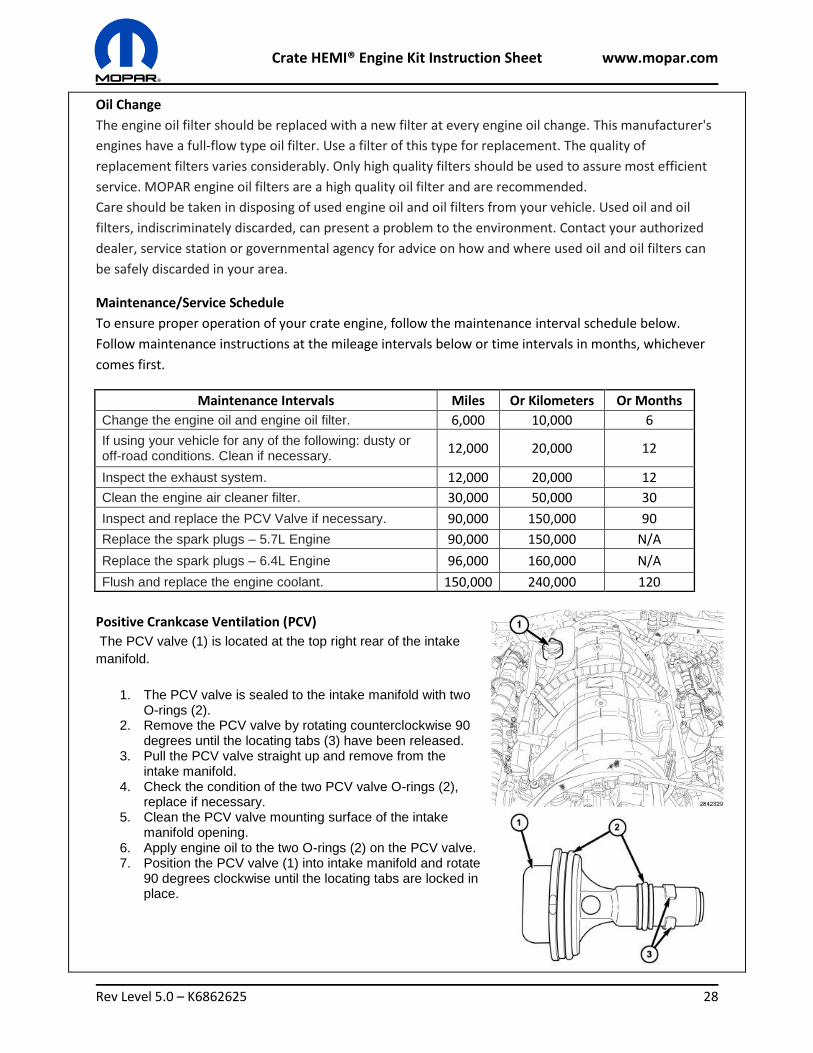
Positive Crankcase Ventilation (PCV)
The PCV valve (1) is located at the top right rear of the intake
manifold.
1. The PCV valve is sealed to the intake manifold with two O-rings (2).
2. Remove the PCV valve by rotating counterclockwise 90 degrees until the locating tabs (3) have been released.
3. Pull the PCV valve straight up and remove from the intake manifold.
4. Check the condition of the two PCV valve O-rings (2), replace if necessary.
5. Clean the PCV valve mounting surface of the intake manifold opening.
6. Apply engine oil to the two O-rings (2) on the PCV valve. 7. Position the PCV valve (1) into intake manifold and rotate
90 degrees clockwise until the locating tabs are locked in place.
Crate HEMI® Engine Kit Instruction Sheet www.mopar.com
Rev Level 5.0 – K6862625 29
Troubleshooting Engine does not crank
1. Battery is dead.
2. Clutch interlock switch not properly connected/faulty.
3. Starter not properly connected.
4. Ignition wiring not properly connected.
5. Blown fuse in PDC.
6. Starter does not engage flywheel correctly.
7. Starter is faulty.
Engine Cranks but does Not Start
1. Powertrain fuses open, inspect all fuses, if an open fuse(s) is found, check the related circuit(s)
for a short to ground or high resistance, repair issue and replace fuse.
2. Fuel pump delivery; verify that the fuel tank is not empty before continuing. Check fuel delivery
system.
3. Check ignition spark.
4. Possible mechanical Issue, engine exhaust system must be free of any restrictions or leaks,
engine valve timing must be within specifications, and check for broken timing components,
engine compression must be within specifications.
Engine Cranks but runs poorly
1. Disconnected sensor or solenoid.
2. Wrong fuel injector location.
3. Wrong ignition coil location.
4. Inadequate fuel flow.
5. Check the CBID for a MIL, if the MIL is ON: connect to the DLC port and diagnose issue.
Other
Please reference the 2016 Dodge Challenger service manuals to diagnose other issues.
Call MOPAR for assistance if you have any questions regarding the instructions. 1-888-528-HEMI (4364)
French and Spanish Instructions available, please call MOPAR.
SHARE YOUR EXPERIENCE WITH MOPAR!
MOPAR would love to hear your thoughts and experiences! Send us a message on our
Facebook page or email us at [email protected] with the subject “Crate Engine”.