cpvc cts fittings & valves - spears mfg co inc part 2 technical... · cpvc cts fittings &...
TRANSCRIPT
1242
Visit our web sitewww.spearsmfg.com
TECHNICAL INFORMATION
CPVCCTS FITTINGS
& VALVESCOPPER-TUBE SIZE
DESIGN & INSTALLATION GUIDE
1243 Spears® Manufacturing Company
CPVC CTS FITTINGS & VALVES
NOT FOR DISTRIBUTION OF COMPRESSED AIR OR GASProgressive Products from Spears® Innovation and Technology
Certifi ed Safe Alternative to Metal Plumbing Systems
Full Line of CTS CPVC Fittings, Pipe, Supply Stops & Ball Valves 1/2" Through 2" Plus Supplemental IPS CPVC in 2-1/2" & Up EverTUFF® CPVC pipe and fi ttings are available for most any size project using Copper Tube Size (CTS) in sizes 1/2" through 2". EverTUFF® Schedule 40 and Schedule 80 CPVC Iron Pipe Size (IPS) are available for sizes 2-1/2" and larger for commercial applications such as multi-story installations when adequate design and installation practices have been utilized .Exceptional Corrosion ResistanceUnlike metal systems, CPVC products never rust, scale, or pit, and will provide many years of maintenance-free service and extended system life.Energy SavingsLow heat conductivity minimizes heat loss in hot water systems.Higher Flow CapacitySmooth interior walls result in lower pressure loss and higher volume than conventional metal systems.Lower System CostsLower material costs than metallic systems, combined with lighter weight and ease of installation, can substantially reduce overall system cost.Suitable for Commercial Hot WaterCTS CPVC products can handle fl uids at service temperatures up to 180°F (82°C). IPS CPVC service temperatures and pressures vary according to pipe size.
All conventional metal plumbing systems corrode leaving their corrosive wastes for deposit into the water system. CPVC thermoplastic system components never corrode. Spears® EverTUFF® CTS CPVC systems of fi ttings, pipe, supply stops & valves are Certifi ed lead-free by NSF International (NSF®) for compliance with California and Vermont low-lead plumbing requirements for safe use in drinking water systems. Approved by national, state and municipal building codes*, Spears® CTS CPVC products are ideally suited for hot and cold water distribution systems in residential and commercial structures, as well as recreational vehicles, modular homes and mobile homes.
*Check state and local codes.
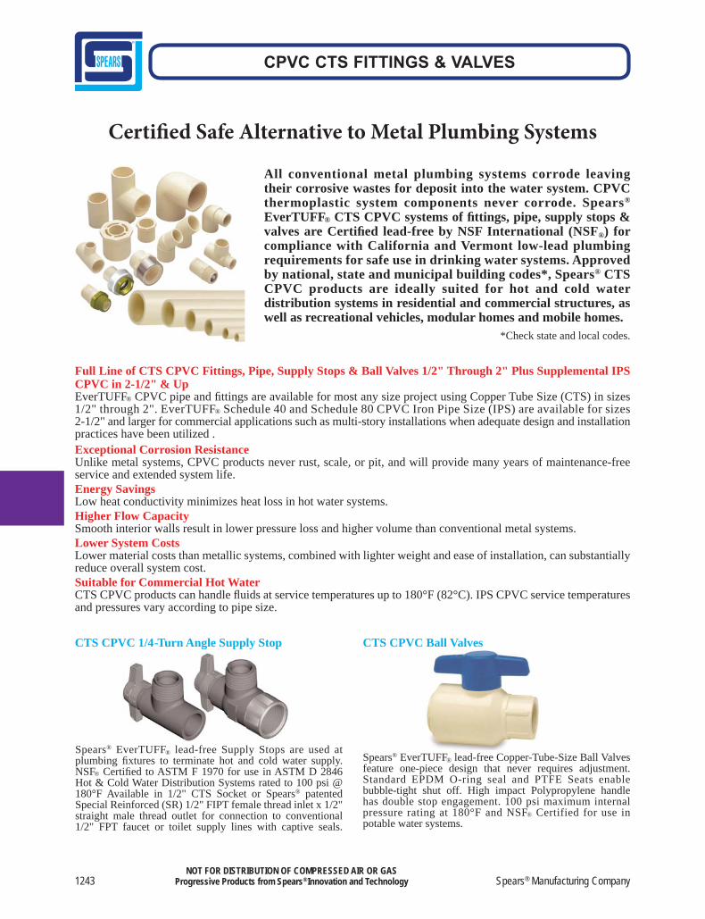
Spears® EverTUFF® lead-free Copper-Tube-Size Ball Valves feature one-piece design that never requires adjustment. Standard EPDM O-ring seal and PTFE Seats enable bubble-tight shut off. High impact Polypropylene handle has double stop engagement. 100 psi maximum internal pressure rating at 180°F and NSF® Certified for use in potable water systems.
Spears® EverTUFF® lead-free Supply Stops are used at plumbing fi xtures to terminate hot and cold water supply. NSF® Certifi ed to ASTM F 1970 for use in ASTM D 2846 Hot & Cold Water Distribution Systems rated to 100 psi @ 180°F Available in 1/2" CTS Socket or Spears® patented Special Reinforced (SR) 1/2" FIPT female thread inlet x 1/2" straight male thread outlet for connection to conventional 1/2" FPT faucet or toilet supply lines with captive seals.
CTS CPVC 1/4-Turn Angle Supply Stop CTS CPVC Ball Valves
Made in the U.S.A. 1244
CPVC CTS FITTINGS & VALVES
NOT FOR DISTRIBUTION OF COMPRESSED AIR OR GASProgressive Products from Spears® Innovation and Technology
Sample Engineering Specifi cationsAll fi ttings, supply stops and valves shall be Copper-Tube-Size (CTS) constructed from CPVC Type IV Cell Classifi cation 23447. All CTS CPVC products shall be produced to applicable requirements of ASTM D 2846 and rated to 100 psi at 180°F, unless specifi cally designated for cold water service only. All supply stops shall be 1/4 turn angle pattern CTS CPVC with male thread outlets. All ball valves shall be CTS CPVC sealed unit type with EPDM O-ring and double stop Polypropylene handle. All CTS CPVC products shall be certifi ed lead-free for potable water use by NSF International in accordance with NSF®-61 Annex G, as manufactured by Spears® Manufacturing Company.
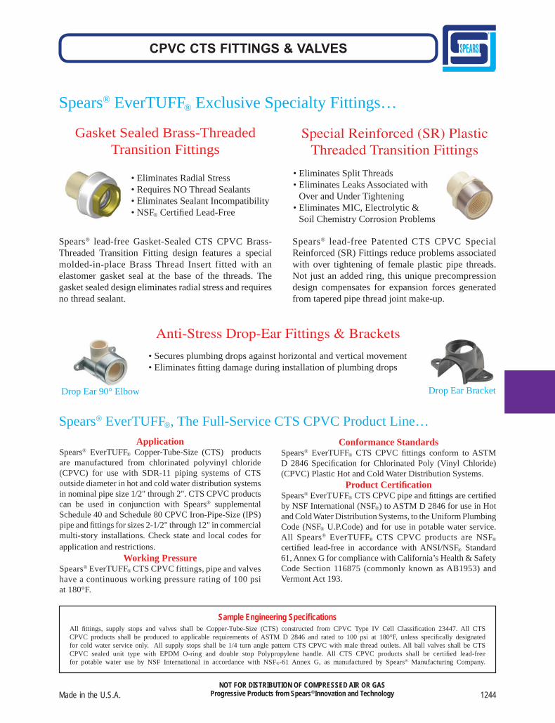
Spears® EverTUFF® Exclusive Specialty Fittings…
Drop Ear 90° Elbow Drop Ear Bracket
Anti-Stress Drop-Ear Fittings & Brackets
• Secures plumbing drops against horizontal and vertical movement• Eliminates fi tting damage during installation of plumbing drops
ApplicationSpears® EverTUFF® Copper-Tube-Size (CTS) products are manufactured from chlorinated polyvinyl chloride (CPVC) for use with SDR-11 piping systems of CTS outside diameter in hot and cold water distribution systems in nominal pipe size 1/2" through 2". CTS CPVC products can be used in conjunction with Spears® supplemental Schedule 40 and Schedule 80 CPVC Iron-Pipe-Size (IPS) pipe and fi ttings for sizes 2-1/2" through 12" in commercial multi-story installations. Check state and local codes for application and restrictions.
Working PressureSpears® EverTUFF® CTS CPVC fittings, pipe and valves have a continuous working pressure rating of 100 psi at 180°F.
Conformance StandardsSpears® EverTUFF® CTS CPVC fi ttings conform to ASTM D 2846 Specifi cation for Chlorinated Poly (Vinyl Chloride) (CPVC) Plastic Hot and Cold Water Distribution Systems.
Product Certifi cationSpears® EverTUFF® CTS CPVC pipe and fi ttings are certifi ed by NSF International (NSF®) to ASTM D 2846 for use in Hot and Cold Water Distribution Systems, to the Uniform Plumbing Code (NSF® U.P.Code) and for use in potable water service. All Spears® EverTUFF® CTS CPVC products are NSF®
certifi ed lead-free in accordance with ANSI/NSF® Standard 61, Annex G for compliance with California’s Health & Safety Code Section 116875 (commonly known as AB1953) and Vermont Act 193.
Spears® EverTUFF®, The Full-Service CTS CPVC Product Line…
Gasket Sealed Brass-Threaded Transition Fittings
• Eliminates Radial Stress• Requires NO Thread Sealants• Eliminates Sealant Incompatibility• NSF® Certifi ed Lead-Free
Spears® lead-free Gasket-Sealed CTS CPVC Brass-Threaded Transition Fitting design features a special molded-in-place Brass Thread Insert fitted with an elastomer gasket seal at the base of the threads. The gasket sealed design eliminates radial stress and requires no thread sealant.
Special Reinforced (SR) Plastic Threaded Transition Fittings
• Eliminates Split Threads • Eliminates Leaks Associated with
Over and Under Tightening• Eliminates MIC, Electrolytic &
Soil Chemistry Corrosion Problems
Spears® lead-free Patented CTS CPVC Special Reinforced (SR) Fittings reduce problems associated with over tightening of female plastic pipe threads. Not just an added ring, this unique precompression design compensates for expansion forces generated from tapered pipe thread joint make-up.
1245 Spears® Manufacturing Company
CPVC CTS FITTINGS & VALVES
NOT FOR DISTRIBUTION OF COMPRESSED AIR OR GASProgressive Products from Spears® Innovation and Technology
ApplicationSpears® Copper Tube Size (CTS) Pipe and Fittings are manufactured from chlorinated polyvinyl chloride (CPVC) for use with SDR 11 piping systems of CTS outside diameter in hot and cold water distribution systems. Check state and local codes for application and restrictions.
Conformance StandardsSpears® CPVC CTS Pipe and Fittings conform to ASTM D 2846 Specification for Chlorinated Poly (Vinyl Chloride) (CPVC) Plastic Hot and Cold Water Distribution Systems.
Working PressureSpears® CPVC CTS Pipe and Fittings have a continuous working pressure rating of 100 psi at 180°F (400 psi at 73°F).
Product CertificationSpears® CPVC CTS Pipe, Fittings and Special Reinforced (SR) Threaded transition adapters are tested and certified by the National Sanitation Foundation (NSF®) to ASTM D 2846 for use in Hot and Cold Water Distribution Systems, and for safe use in potable water systems under NSF® Standard 14/61.All Spears® CPVC CTS Pipe and Fittings for CPVC Plastic Hot and Cold Water Distribution Systems in this manual are certified Lead-Free by NSF International under NSF® Standard 61, Annex G. The annex certifies compliance to California California’s Health & Safety Code Section 116875 (commonly known as AB1953) and Vermont Act 193. Lead free is defined by these requirements as containing no more than a weighted average lead content of <=0.25%.
TestingOnce the system has been installed and allowed to cure properly, the system shall be tested in accordance with applicable code requirements. When testing with water (hydrostatic testing), the system must be slowly filled with water and the air bled from the highest and furthest points in the system before test pressure is applied. Failure to do so can cause damage to the piping system and could be harmful to the job site personnel should a failure occur. If a leak is found, the affected product must be cut and discarded. A new section can be installed using couplings or other approved means.
PURPOSE OF THIS MANUAL
HAZARD IDENTIFICATION
This manual is intended for use by specifiers, installers, and users in the selection, design, installation, and inspection of CPVC systems installed using Spears® CPVC products. All information contained within this manual is considered vital to obtain proper system performance and must be read and fully understood before attempting to install these products. If you have any questions about the safe and proper installation of these products, contact Spears® Manufacturing Company 15853 Olden Street, Sylmar CA 91342 USA, Telephone (818) 364-1611 • (800) 862-1499.
Defi nitions for identifying the various hazard levels are provided below.
This safety alert symbol indicates important safety messages. When you see this symbol, be alert to the possibility of personal injury. Carefully read and fully understand the message that follows.
DANGERThe use of the word “DANGER” identifi es an immediate hazard with a likelihood of severe personal injury or death if instructions, including recommended precautions, are not followed.
WARNINGThe use of the word “WARNING” identifi es the presence of hazards or unsafe practices that could result in severe personal injury if instructions, including recommended precautions, are not followed.
CAUTIONThe use of the word “CAUTION” identifi es possible hazards or unsafe prac-tices that could result in personal injury, product damage, and/or property damage if instructions, including recommended precautions, are not followed.
NOTICEThe use of the word “NOTICE” identifi es special instructions that are important but not related to hazards.
The information contained in this publication is based on current information and Product design at the time of publication and is subject to change without notification. Our ongoing commitment to product improvement may result in some variation. No representations, guarantees or warranties of any kind are made as to its accuracy, suitability for particular applications or results to be obtained therefrom. For verification of technical data or additional information not contained herein, please contact Spears® Technical Services Department [West Coast: (818) 364-1611 — East Coast: (678) 985-1263].
Made in the U.S.A. 1246
CPVC CTS FITTINGS & VALVES
NOT FOR DISTRIBUTION OF COMPRESSED AIR OR GASProgressive Products from Spears® Innovation and Technology
Code OrganizationBOCA National Plumbing Code Building Offi cials and Code Administrators International, Inc.
CABO 1- and 2-Family Dwelling Code Council of American Building Offi cials
Canadian Plumbing Code National Research Council, Canada
International Plumbing Code BOCA, ICBO, SBCCI
National Standard Plumbing Code National Association of Plumbing-Heating-Cooling Contractors
Standard Plumbing Code Southern Building Code Congress International Inc.
Uniform Plumbing Code International Association of Plumbing and Mechanical Offi cials
LISTING AGENCIESStandard Organization
Standards 14 and 61 NSF International (ANSI/NSF®)
Read and understand this manual before proceeding with the installation and testing of the Spears® CPVC system. Education and a complete understanding of the instructions provided are requirements for the installer of the Spears® CPVC system. These instructions contain important information. If you need additional copies of this manual, or if you have any questions about the safe installation and use of this system, contact Spears® Manufacturing Company 15853 Olden Street, Sylmar CA 91342 USA, Telephone (818) 364-1611 • (800) 862-1499.
INSTALLER SAFETY INSTRUCTIONS
MODEL CODESSpears® CPVC products meet ASTM D 2846 requirements, as referenced in the current version of the following model codes.
1.
2.
3.
4.
5.
6.
7.
8.
9.
10.
11.
12.
Inspect the product. Make sure all parts are included with the shipment and that all necessary tools are available for proper installation.
Wear safety glasses, hard hat, and foot protection.
Avoid dangerous environments. If using electrically powered tools for installation, make sure the area is free from moisture or wetness that could create unsafe working conditions. Keep work areas well lit. Allow suffi cient space for measuring and dry-fi tting the system.
Prevent back injury. Always practice safe lifting and installation techniques.
Use only tools specifi cally designed for plastic pipe and fi ttings.
Work in a well-ventilated area. Ensure that there is proper ventilation when applying primers and cements and/or soldering materials.
Wear protective gloves. PVA-coated protective gloves are recommended when applying solvent cement. If hands contact solvent cement, use a waterless, abrasive soap to remove all residue.
When solvent cementing, avoid sources of heat or open fl ame. DO NOT smoke while handling solvent cement.
Keep work areas clean. Cluttered areas and slippery fl oors can create hazardous working conditions.
Wear hearing protection. Protect your hearing if you are exposed to long periods of very noisy job-site operations.
Keep visitors away. All visitors should be kept a safe distance away from the work area.
Follow all manufacturers’ recommended precautions when cutting or sawing pipes, or when using any heat, fl ame, or power tools.
1247 Spears® Manufacturing Company
CPVC CTS FITTINGS & VALVES
NOT FOR DISTRIBUTION OF COMPRESSED AIR OR GASProgressive Products from Spears® Innovation and Technology
HANDLING AND STORAGE
SYSTEM LISTINGS, USAGE,AND STANDARDS
Spears® CPVC products resist attack from a large group of chemi-cals that are corrosive to metallic piping. However, care must be taken to avoid contact with chemicals that are harmful to CPVC. Specific chemicals, or chemical vapors, that contact CPVC can weaken or damage the system. Consult with Spears® before using these CPVC products with any questionable materials.
Spears® recommends that CPVC products be stored indoors. If storing outdoors, these products must be covered with a non-transparent material to prevent extended sunlight exposure. Brief exposure to direct sunlight on the job site may result in color fade, but it will not affect the material’s physical properties. Spears® CPVC fi ttings should be stored in their original containers to keep them free from dirt and to help reduce the possibility of damage.
Reasonable care must be exercised in handling Spears® CPVC products. Do not drop these products or allow anything to drop on them. If improper handling results in scratches, splits, or gouges, the damaged fi tting or section of piping must be discarded.
Spears® CPVC products can be used within fi re-rated buildings, provided all penetrations of fi re barriers are constructed so that the fi re rating of the barrier is not compromised. Most codes ac-cept penetration sealing systems or devices that are UL Listed or have passed the appropriate ASTM E 119 or E 814 tests. The PPFA manual, “Plastic Pipe in Fire Restrictive Construction” (NER370), provides more information and lists the applicable test reports. In addition, reference can be made to the current issue of the “Underwriters Laboratories Inc. Directories of Fire Resistance – Vol. II” or the “WHI Certifi cation Listings.” Before starting an instal-lation, always consult the building codes and local authority having jurisdiction.
Penetrating Fire-Rated Walls andPartitions
WARNING• DO NOT expose Spears® CPVC products to edible oils, esters, ketones, or petro-
leum-based products, such as: cutting oils; packing oils; traditional pipe thread paste or dopes; and certain lubricants. Consult with Spears® before using certain chemicals with these CPVC products.
Failure to follow this instruction could cause product/system damage, resulting in serious personal injury and/or property damage.
WARNING• Spears® CPVC products must not be subjected to prolonged sunlight exposure. • For outdoor storage, products must be stored in their original shipping containers,
or they must be covered with a non-transparent material. Failure to follow this instruction could cause product/system damage, resulting in serious personal injury and/or property damage.
WARNING• Some fi re-stopping systems contain chemicals that can damage CPVC products.
Always consult with Spears® and the fi re-stop manufacturer concerning compatibility with CPVC products.
Failure to follow this instruction could cause product/system damage, resulting inserious personal injury and/or property damage.
Underslab InstallationsSpears® CPVC products are approved for underslab installations (with joints) in all model-plumbing codes. When performing underslab installations, it is important to support the pipe evenly on a smooth surface. The bedding and backfi ll should be sand or clean soil that is free from sharp rocks and other debris that could damage the pipe. Underslab installations that contain joints must be pressure tested before pouring the slab. NOTE: IAPMO IS 2098, “Installation Standard for CPVC Solvent Cemented Hot and Cold Water Distri-bution Systems,” requires a test at 150 psi for 2 hours. The pipe should be sleeved where it penetrates the slab, along with construc-tion joints within the slab. Spears® CPVC products can be used with pipe manufactured in accordance with ASTM D 2846, which is available in coils for under-slab installations. When turning coiled piping up through a slab, into walls, etc., make sure the piping does not kink. Sections of pipe that contain kinks must be cut out and replaced.
Made in the U.S.A. 1248
CPVC CTS FITTINGS & VALVES
NOT FOR DISTRIBUTION OF COMPRESSED AIR OR GASProgressive Products from Spears® Innovation and Technology
Freeze Protection/Sunlight ExposureCPVC piping must be protected from freezing in all installation locations. Attention shall be paid to local insulating techniques and codes that require a particular method. Use only methods and materials suitable for use with CPVC piping. Where freezing is not an issue, CPVC shall not be installed so as to be subject to direct sunlight after installation and not installed on the surface of a build-ing, unless protected by a covering or a chemically compatible paint, such as water based Latex.
Hose Bibb InstallationHose bibbs are to be connected only to metal system components which are adequately anchored to the building structure. CPVC plastic systems must terminate in the wall.
Water Heater ConnectionsBefore attempting to use Spears® CPVC products in water heater connections, determine if local plumbing codes contain detailed requirements for connections to gas or electric storage-type heat-ers. DO NOT use Spears® CPVC products with commercial-type, non-storage water heaters.For areas where local plumbing codes do not have require-ments, the following information can be used as a guide for water heater connections: • On electric water heaters, CPVC can be joined directly to the
heater, using metal-to-CPVC transition fi ttings. • On high-effi ciency gas water heaters that use plastic vent piping,
CPVC can be joined directly to the heater in the same way as an electric water-heater connection.
• On all other gas water heaters, there should be at least 6" of clear-ance between the exhaust fl ue and any CPVC piping. A minimum of 6" metallic pipe should connect directly to the heater so that the CPVC piping cannot be damaged by the buildup of excessive, radiant heat from the fl ue.
• A temperature/pressure relief valve should be installed so that the sensing element contacts the water at the top of the heater.
• Spears® CPVC products are approved by all model codes for use as relief-valve drain lines. A metal-to-CPVC transition fi tting should be used to connect the piping to the relief valve. Then, the piping should be continued to the outlet. Both horizontal and vertical pressure relief drain should be supported every 3 feet.
• For horizontal runs, slope the piping toward the outlet. Sup-port the piping at 3-foot centers or closer. The piping must discharge to the atmosphere at an approved location.
• Instantaneous water heaters (i.e., under sink units) require at least 6" of metallic pipe connected to heater inlet and no CVPC installed down stream.
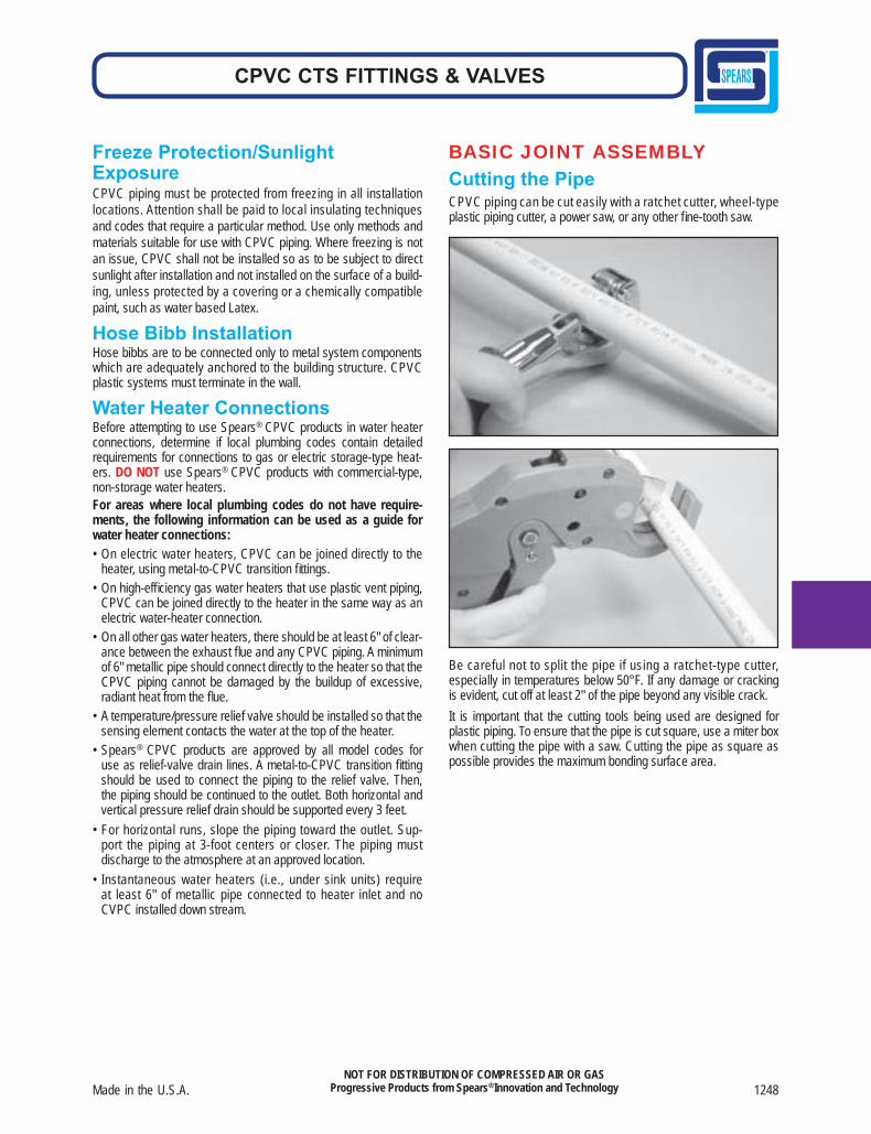
BASIC JOINT ASSEMBLYCutting the PipeCPVC piping can be cut easily with a ratchet cutter, wheel-type plastic piping cutter, a power saw, or any other fi ne-tooth saw.
Be careful not to split the pipe if using a ratchet-type cutter, especially in temperatures below 50°F. If any damage or cracking is evident, cut off at least 2" of the pipe beyond any visible crack. It is important that the cutting tools being used are designed for plastic piping. To ensure that the pipe is cut square, use a miter box when cutting the pipe with a saw. Cutting the pipe as square as possible provides the maximum bonding surface area.
1249 Spears® Manufacturing Company
CPVC CTS FITTINGS & VALVES
NOT FOR DISTRIBUTION OF COMPRESSED AIR OR GASProgressive Products from Spears® Innovation and Technology
Burrs Being Removedfrom Outside
Burrs Being Removedfrom Inside
Bevel
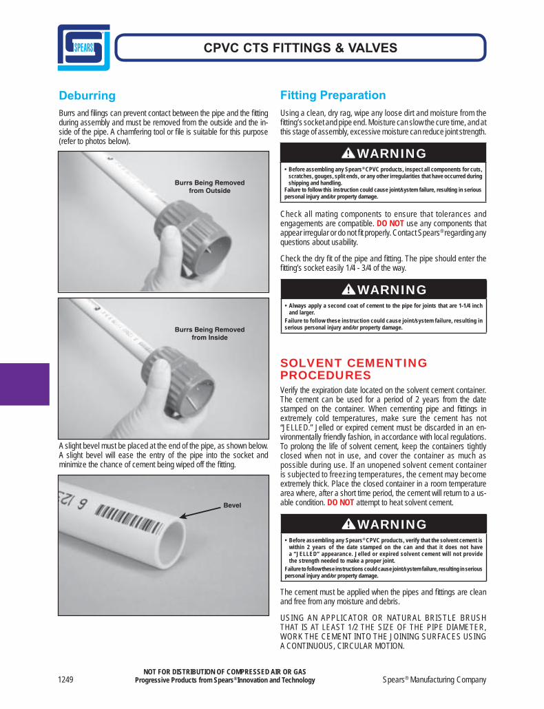
DeburringBurrs and fi lings can prevent contact between the pipe and the fi tting during assembly and must be removed from the outside and the in-side of the pipe. A chamfering tool or fi le is suitable for this purpose (refer to photos below).
A slight bevel must be placed at the end of the pipe, as shown below. A slight bevel will ease the entry of the pipe into the socket and minimize the chance of cement being wiped off the fi tting.
Fitting PreparationUsing a clean, dry rag, wipe any loose dirt and moisture from the fi tting’s socket and pipe end. Moisture can slow the cure time, and at this stage of assembly, excessive moisture can reduce joint strength.
Check all mating components to ensure that tolerances and engagements are compatible. DO NOT use any components that appear irregular or do not fi t properly. Contact Spears® regarding any questions about usability.
Check the dry fi t of the pipe and fi tting. The pipe should enter the fi tting’s socket easily 1/4 - 3/4 of the way.
SOLVENT CEMENTINGPROCEDURESVerify the expiration date located on the solvent cement container. The cement can be used for a period of 2 years from the date stamped on the container. When cementing pipe and fi ttings in extremely cold temperatures, make sure the cement has not “JELLED.” Jelled or expired cement must be discarded in an en-vironmentally friendly fashion, in accordance with local regulations. To prolong the life of solvent cement, keep the containers tightly closed when not in use, and cover the container as much as possible during use. If an unopened solvent cement container is subjected to freezing temperatures, the cement may become extremely thick. Place the closed container in a room temperature area where, after a short time period, the cement will return to a us-able condition. DO NOT attempt to heat solvent cement.
The cement must be applied when the pipes and fi ttings are clean and free from any moisture and debris.
USING AN APPLICATOR OR NATURAL BRISTLE BRUSH THAT IS AT LEAST 1/2 THE SIZE OF THE PIPE DIAMETER, WORK THE CEMENT INTO THE JOINING SURFACES USING A CONTINUOUS, CIRCULAR MOTION.
WARNING• Before assembling any Spears® CPVC products, inspect all components for cuts,
scratches, gouges, split ends, or any other irregularities that have occurred during shipping and handling.
Failure to follow this instruction could cause joint/system failure, resulting in serious personal injury and/or property damage.
WARNING• Always apply a second coat of cement to the pipe for joints that are 1-1/4 inch
and larger.Failure to follow these instruction could cause joint/system failure, resulting in serious personal injury and/or property damage.
WARNING• Before assembling any Spears® CPVC products, verify that the solvent cement is
within 2 years of the date stamped on the can and that it does not have a “JELLED” appearance. Jelled or expired solvent cement will not provide the strength needed to make a proper joint.
Failure to follow these instructions could cause joint/system failure, resulting in serious personal injury and/or property damage.
Made in the U.S.A. 1250
CPVC CTS FITTINGS & VALVES
NOT FOR DISTRIBUTION OF COMPRESSED AIR OR GASProgressive Products from Spears® Innovation and Technology
ContinuousBead
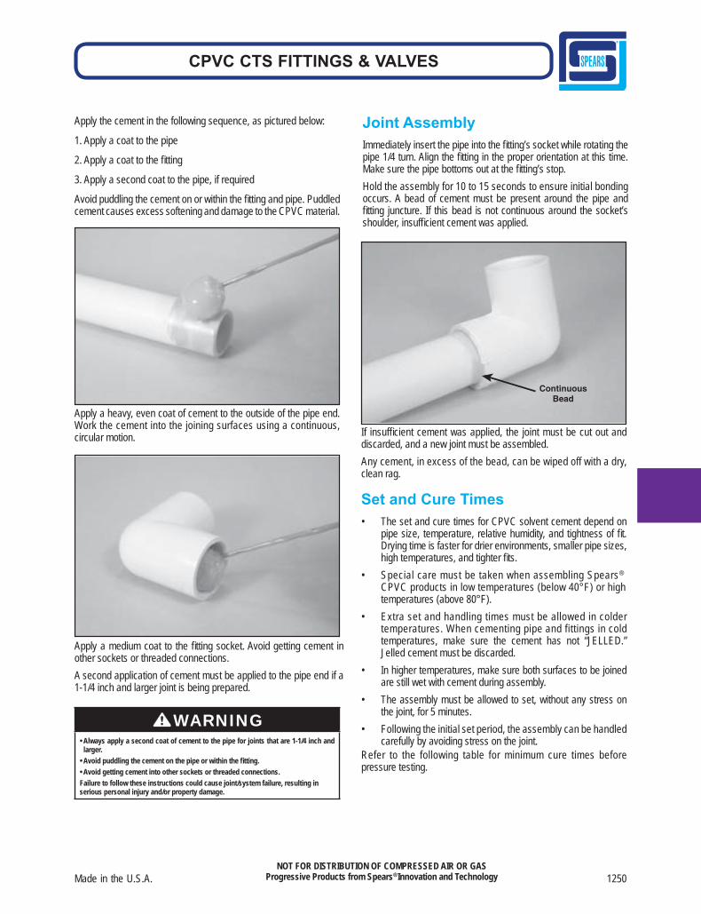
Apply the cement in the following sequence, as pictured below:
1. Apply a coat to the pipe
2. Apply a coat to the fi tting
3. Apply a second coat to the pipe, if required
Avoid puddling the cement on or within the fi tting and pipe. Puddled cement causes excess softening and damage to the CPVC material.
Apply a heavy, even coat of cement to the outside of the pipe end. Work the cement into the joining surfaces using a continuous, circular motion.
Apply a medium coat to the fi tting socket. Avoid getting cement in other sockets or threaded connections. A second application of cement must be applied to the pipe end if a 1-1/4 inch and larger joint is being prepared.
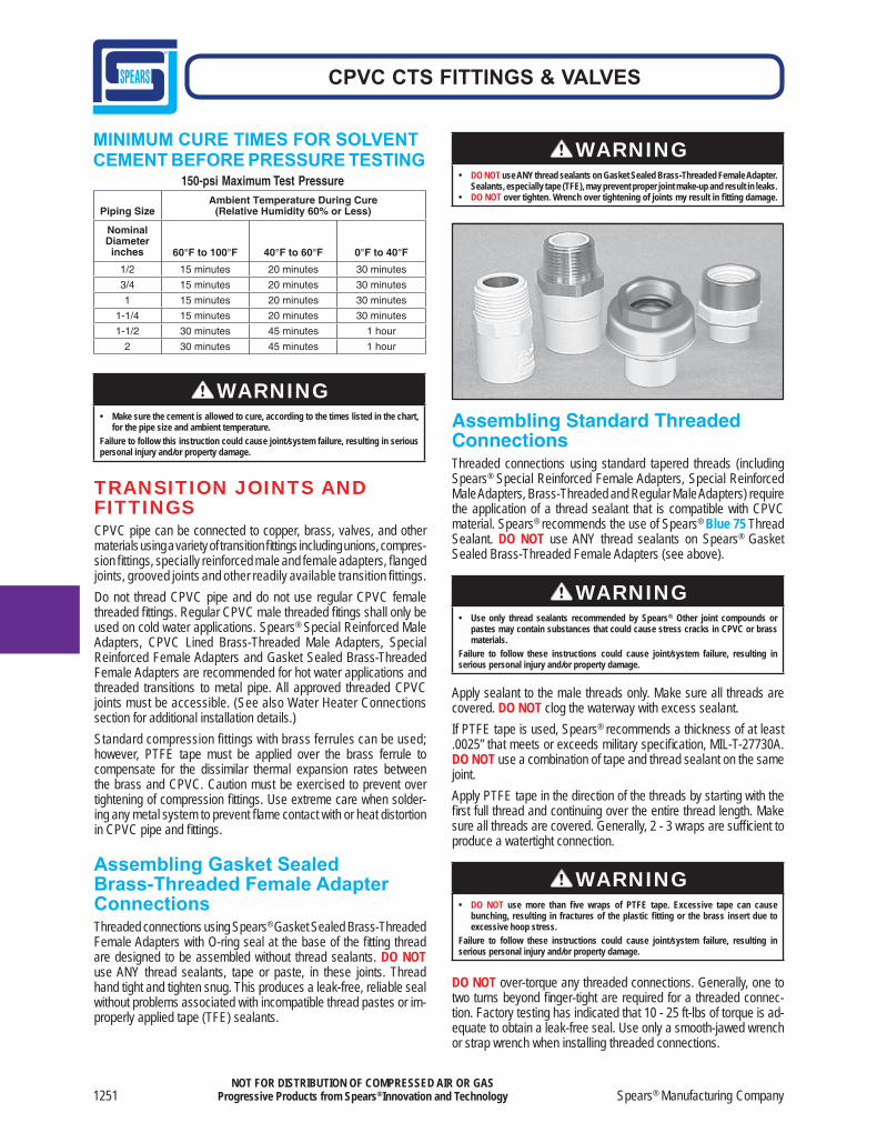
Joint AssemblyImmediately insert the pipe into the fi tting’s socket while rotating the pipe 1/4 turn. Align the fi tting in the proper orientation at this time. Make sure the pipe bottoms out at the fi tting’s stop. Hold the assembly for 10 to 15 seconds to ensure initial bonding occurs. A bead of cement must be present around the pipe and fi tting juncture. If this bead is not continuous around the socket’s shoulder, insuffi cient cement was applied.
If insuffi cient cement was applied, the joint must be cut out and discarded, and a new joint must be assembled. Any cement, in excess of the bead, can be wiped off with a dry, clean rag.
Set and Cure Times• The set and cure times for CPVC solvent cement depend on
pipe size, temperature, relative humidity, and tightness of fi t. Drying time is faster for drier environments, smaller pipe sizes, high temperatures, and tighter fi ts.
• Special care must be taken when assembling Spears®
CPVC products in low temperatures (below 40°F) or high temperatures (above 80°F).
• Extra set and handling times must be allowed in colder temperatures. When cementing pipe and fittings in cold temperatures, make sure the cement has not “JELLED.” Jelled cement must be discarded.
• In higher temperatures, make sure both surfaces to be joined are still wet with cement during assembly.
• The assembly must be allowed to set, without any stress on the joint, for 5 minutes.
• Following the initial set period, the assembly can be handled carefully by avoiding stress on the joint.
Refer to the following table for minimum cure times before pressure testing.
WARNING• Always apply a second coat of cement to the pipe for joints that are 1-1/4 inch and
larger. • Avoid puddling the cement on the pipe or within the fi tting. • Avoid getting cement into other sockets or threaded connections. Failure to follow these instructions could cause joint/system failure, resulting in serious personal injury and/or property damage.
1251 Spears® Manufacturing Company
CPVC CTS FITTINGS & VALVES
NOT FOR DISTRIBUTION OF COMPRESSED AIR OR GASProgressive Products from Spears® Innovation and Technology
Piping SizeAmbient Temperature During Cure
(Relative Humidity 60% or Less)
NominalDiameterinches 60°F to 100°F 40°F to 60°F 0°F to 40°F
1/2 15 minutes 20 minutes 30 minutes
3/4 15 minutes 20 minutes 30 minutes
1 15 minutes 20 minutes 30 minutes
1-1/4 15 minutes 20 minutes 30 minutes
1-1/2 30 minutes 45 minutes 1 hour
2 30 minutes 45 minutes 1 hour
150-psi Maximum Test Pressure
MINIMUM CURE TIMES FOR SOLVENT CEMENT BEFORE PRESSURE TESTING
TRANSITION JOINTS ANDFITTINGSCPVC pipe can be connected to copper, brass, valves, and other materials using a variety of transition fi ttings including unions, compres-sion fi ttings, specially reinforced male and female adapters, fl anged joints, grooved joints and other readily available transition fittings.Do not thread CPVC pipe and do not use regular CPVC female threaded fi ttings. Regular CPVC male threaded fi tings shall only be used on cold water applications. Spears® Special Reinforced Male Adapters, CPVC Lined Brass-Threaded Male Adapters, Special Reinforced Female Adapters and Gasket Sealed Brass-Threaded Female Adapters are recommended for hot water applications and threaded transitions to metal pipe. All approved threaded CPVC joints must be accessible. (See also Water Heater Connections section for additional installation details.)Standard compression fittings with brass ferrules can be used; however, PTFE tape must be applied over the brass ferrule to compensate for the dissimilar thermal expansion rates between the brass and CPVC. Caution must be exercised to prevent over tightening of compression fi ttings. Use extreme care when solder-ing any metal system to prevent fl ame contact with or heat distortion in CPVC pipe and fi ttings.
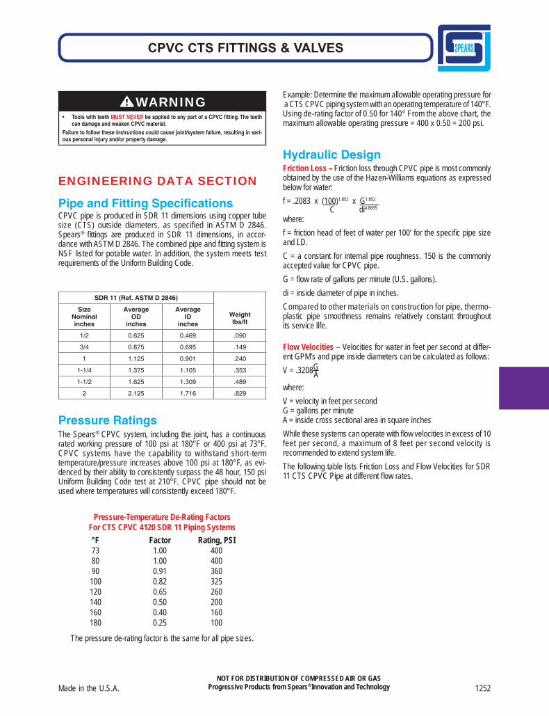
Assembling Standard Threaded ConnectionsThreaded connections using standard tapered threads (including Spears® Special Reinforced Female Adapters, Special Reinforced Male Adapters, Brass-Threaded and Regular Male Adapters) require the application of a thread sealant that is compatible with CPVC material. Spears® recommends the use of Spears® Blue 75 Thread Sealant. DO NOT use ANY thread sealants on Spears® Gasket Sealed Brass-Threaded Female Adapters (see above).
Apply sealant to the male threads only. Make sure all threads are covered. DO NOT clog the waterway with excess sealant. If PTFE tape is used, Spears® recommends a thickness of at least .0025” that meets or exceeds military specifi cation, MIL-T-27730A. DO NOT use a combination of tape and thread sealant on the same joint. Apply PTFE tape in the direction of the threads by starting with the fi rst full thread and continuing over the entire thread length. Make sure all threads are covered. Generally, 2 - 3 wraps are suffi cient to produce a watertight connection.
DO NOT over-torque any threaded connections. Generally, one to two turns beyond fi nger-tight are required for a threaded connec-tion. Factory testing has indicated that 10 - 25 ft-lbs of torque is ad-equate to obtain a leak-free seal. Use only a smooth-jawed wrench or strap wrench when installing threaded connections.
Assembling Gasket Sealed Brass-Threaded Female Adapter ConnectionsThreaded connections using Spears® Gasket Sealed Brass-Threaded Female Adapters with O-ring seal at the base of the fi tting thread are designed to be assembled without thread sealants. DO NOT use ANY thread sealants, tape or paste, in these joints. Thread hand tight and tighten snug. This produces a leak-free, reliable seal without problems associated with incompatible thread pastes or im-properly applied tape (TFE) sealants.
WARNING• Make sure the cement is allowed to cure, according to the times listed in the chart,
for the pipe size and ambient temperature. Failure to follow this instruction could cause joint/system failure, resulting in serious personal injury and/or property damage.
WARNING• DO NOT use ANY thread sealants on Gasket Sealed Brass-Threaded Female Adapter.
Sealants, especially tape (TFE), may prevent proper joint make-up and result in leaks. • DO NOT over tighten. Wrench over tightening of joints my result in fi tting damage.
WARNING• Use only thread sealants recommended by Spears®. Other joint compounds or
pastes may contain substances that could cause stress cracks in CPVC or brass materials.
Failure to follow these instructions could cause joint/system failure, resulting in serious personal injury and/or property damage.
WARNING• DO NOT use more than fi ve wraps of PTFE tape. Excessive tape can cause
bunching, resulting in fractures of the plastic fi tting or the brass insert due to excessive hoop stress.
Failure to follow these instructions could cause joint/system failure, resulting in serious personal injury and/or property damage.
Made in the U.S.A. 1252
CPVC CTS FITTINGS & VALVES
NOT FOR DISTRIBUTION OF COMPRESSED AIR OR GASProgressive Products from Spears® Innovation and Technology
ENGINEERING DATA SECTION
Pipe and Fitting Specifi cationsCPVC pipe is produced in SDR 11 dimensions using copper tube size (CTS) outside diameters, as specified in ASTM D 2846. Spears® fi ttings are produced in SDR 11 dimensions, in accor-dance with ASTM D 2846. The combined pipe and fi tting system is NSF listed for potable water. In addition, the system meets test requirements of the Uniform Building Code.
Pressure RatingsThe Spears® CPVC system, including the joint, has a continuous rated working pressure of 100 psi at 180°F or 400 psi at 73°F. CPVC systems have the capability to withstand short-term temperature/pressure increases above 100 psi at 180°F, as evi-denced by their ability to consistently surpass the 48 hour, 150 psi Uniform Building Code test at 210°F. CPVC pipe should not be used where temperatures will consistently exceed 180°F.
Pressure-Temperature De-Rating Factors For CTS CPVC 4120 SDR 11 Piping Systems
°F Factor Rating, PSI 73 1.00 400 80 1.00 400 90 0.91 360 100 0.82 325 120 0.65 260 140 0.50 200 160 0.40 160 180 0.25 100
The pressure de-rating factor is the same for all pipe sizes.
Example: Determine the maximum allowable operating pressure for a CTS CPVC piping system with an operating temperature of 140°F. Using de-rating factor of 0.50 for 140° From the above chart, the maximum allowable operating pressure = 400 x 0.50 = 200 psi.
Hydraulic DesignFriction Loss – Friction loss through CPVC pipe is most commonly obtained by the use of the Hazen-Williams equations as expressed below for water: 1.852f = .2083 x (100)1.852 x G C di4.8655
where:f = friction head of feet of water per 100’ for the specifi c pipe size and I.D.C = a constant for internal pipe roughness. 150 is the commonly accepted value for CPVC pipe.G = fl ow rate of gallons per minute (U.S. gallons).di = inside diameter of pipe in inches.Compared to other materials on construction for pipe, thermo-plastic pipe smoothness remains relatively constant throughout its service life.
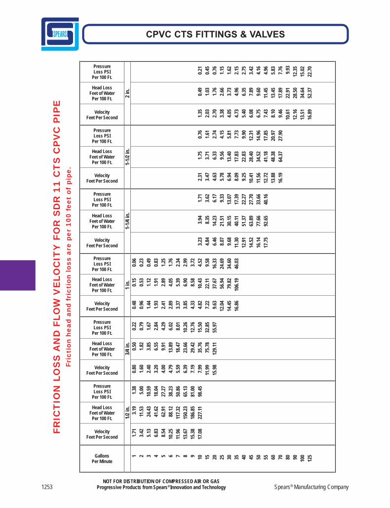
Flow Velocities – Velocities for water in feet per second at differ-ent GPM’s and pipe inside diameters can be calculated as follows:V = .3208G Awhere:V = velocity in feet per secondG = gallons per minuteA = inside cross sectional area in square inchesWhile these systems can operate with fl ow velocities in excess of 10 feet per second, a maximum of 8 feet per second velocity is recommended to extend system life.The following table lists Friction Loss and Flow Velocities for SDR 11 CTS CPVC Pipe at different fl ow rates.
SDR 11 (Ref. ASTM D 2846)
Weightlbs/ft
SizeNominalinches
AverageOD
inches
AverageID
inches
1/2 0.625 0.469 .090
3/4 0.875 0.695 .149
1 1.125 0.901 .240
1-1/4 1.375 1.105 .353
1-1/2 1.625 1.309 .489
2 2.125 1.716 .829
WARNING• Tools with teeth MUST NEVER be applied to any part of a CPVC fitting. The teeth
can damage and weaken CPVC material. Failure to follow these instructions could cause joint/system failure, resulting in seri-ous personal injury and/or property damage.
1253 Spears® Manufacturing Company
CPVC CTS FITTINGS & VALVES
NOT FOR DISTRIBUTION OF COMPRESSED AIR OR GASProgressive Products from Spears® Innovation and Technology
GallonsPer Minute
VelocityFeet Per Second
Head LossFeet of Water
Per 100 Ft.
PressureLoss PSI
Per 100 Ft.
VelocityFeet Per Second
Head LossFeet of Water
Per 100 Ft.
PressureLoss PSI
Per 100 Ft.
VelocityFeet Per Second
Head LossFeet of Water
Per 100 Ft.
PressureLoss PSI
Per 100 Ft.
VelocityFeet Per Second
Head LossFeet of Water
Per 100 Ft.
PressureLoss PSI
Per 100 Ft.
VelocityFeet Per Second
Head LossFeet of Water
Per 100 Ft.
PressureLoss PSI
Per 100 Ft.
VelocityFeet Per Second
Head LossFeet of Water
Per 100 Ft.
PressureLoss PSI
Per 100 Ft.
1/2 in
.3/4
in.
1 in.
1-1/4
in.
1-1/2
in.
2 in.
1
2
3
4
5
6
7
8
9
10
15
20
25
30
35
40
45
50
55
60
70
80
90
100
125
1.71
3.42
5.13
6.83
8.54
10.25
11.96
13.67
15.38
17.08
3.1
9 1
1.53
24.4
3 4
1.62
62.9
1 8
8.12
117.3
215
0.23
186.8
522
7.11
1.38
5.00
10.59
18.04
27.27
38.23
50.86
65.13
81.00
98.45
0.80
1.60
2.40
3.20
4.00
4.79
5.59
6.39
7.19
7.99
11.99
15.98
0.5
0
1.82
3.8
5
6.55
9.9
1 1
3.89
18.4
7 2
3.66
29.4
2 3
5.76
75.7
812
9.11
0.22
0.79
1.67
2.84
4.29
6.02
8.01
10.26
12.76
15.50
32.85
55.97
0.48
0.96
1.44
1.93
2.41
2.89
3.37
3.85
4.33
4.82
7.22
9.63
12.04
14.45
16.86
0.1
5
0.53
1.1
2
1.91
2.8
9
4.05
5.3
9
6.90
8.5
8 1
0.43
22.1
1 3
7.67
56.9
4 7
9.82
106.1
9
0.06
0.23
0.49
0.83
1.25
1.76
2.34
2.99
3.72
4.52
9.58
16.33
24.69
34.60
46.03
3.23
4.84
6.46
8.07
9.68
11.30
12.91
14.52
16.14
17.75
3.94
8.35
14.23
21.51
30.15
40.11
51.37
63.89
77.66
92.65
1.71
3.62
6.17
9.33
13.07
17.39
22.27
27.70
33.66
40.16
2.31
3.47
4.63
5.78
6.94
8.09
9.25
10.41
11.56
12.72
13.88
16.19
1.75
3.71
6.33
9.56
13.40
17.83
22.83
28.40
34.52
41.18
48.38
64.37
0.76
1.61
2.74
4.15
5.81
7.73
9.90
12.31
14.96
17.85
20.97
27.90
1.35
2.03
2.70
3.38
4.05
4.73
5.40
6.08
6.75
7.43
8.10
9.46
10.61
12.16
13.51
16.89
0.49
1.03
1.76
2.66
3.73
4.96
6.35
7.89
9.60
11.45
13.45
17.89
22.91
28.50
34.64
52.37
0.21
0.45
0.76
1.15
1.62
2.15
2.75
3.42
4.16
4.96
5.83
7.76
9.93
12.35
15.02
22.70
FRIC
TIO
N L
OS
S A
ND
FLO
W V
ELO
CIT
Y F
OR
SD
R 1
1 C
TS
CP
VC
PIP
EFr
icti
on h
ead
and
fric
tion
loss
are
per
100
fee
t of
pip
e.
Made in the U.S.A. 1254
CPVC CTS FITTINGS & VALVES
NOT FOR DISTRIBUTION OF COMPRESSED AIR OR GASProgressive Products from Spears® Innovation and Technology
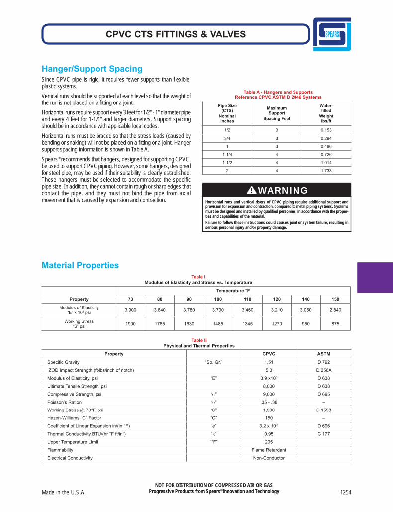
Hanger/Support SpacingSince CPVC pipe is rigid, it requires fewer supports than fl exible, plastic systems. Vertical runs should be supported at each level so that the weight of the run is not placed on a fi tting or a joint. Horizontal runs require support every 3 feet for 1/2" - 1" diameter pipe and every 4 feet for 1-1/4" and larger diameters. Support spacing should be in accordance with applicable local codes.Horizontal runs must be braced so that the stress loads (caused by bending or snaking) will not be placed on a fi tting or a joint. Hanger support spacing information is shown in Table A. Spears® recommends that hangers, designed for supporting CPVC, be used to support CPVC piping. However, some hangers, designed for steel pipe, may be used if their suitability is clearly established. These hangers must be selected to accommodate the specific pipe size. In addition, they cannot contain rough or sharp edges that contact the pipe, and they must not bind the pipe from axial movement that is caused by expansion and contraction.
Pipe Size(CTS)
Nominalinches
MaximumSupport
Spacing Feet
Water-fi lled
Weightlbs/ft
1/2 3 0.153
3/4 3 0.294
1 3 0.486
1-1/4 4 0.726
1-1/2 4 1.014
2 4 1.733
Property
Temperature °F
73 80 90 100 110 120 140 150
Modulus of Elasticity“E” x 105 psi 3.900 3.840 3.780 3.700 3.460 3.210 3.050 2.840
Working Stress“S” psi 1900 1785 1630 1485 1345 1270 950 875
Property CPVC ASTM
Specifi c Gravity “Sp. Gr.” 1.51 D 792
IZOD Impact Strength (ft-lbs/inch of notch) 5.0 D 256A
Modulus of Elasticity, psi “E” 3.9 x10⁵ D 638
Ultimate Tensile Strength, psi 8,000 D 638
Compressive Strength, psi “σ” 9,000 D 695
Poisson’s Ration “υ” .35 - .38 –
Working Stress @ 73°F, psi “S” 1,900 D 1598
Hazen-Williams “C” Factor “C” 150 –
Coeffi cient of Linear Expansion in/(in °F) “e” 3.2 x 10⁻⁵ D 696
Thermal Conductivity BTU/(hr °F ft/in2) “k” 0.95 C 177
Upper Temperature Limit “°F” 205
Flammability Flame Retardant
Electrical Conductivity Non-Conductor
Table A - Hangers and SupportsReference CPVC ASTM D 2846 Systems
Material PropertiesTable I
Modulus of Elasticity and Stress vs. Temperature
Table IIPhysical and Thermal Properties
WARNINGHorizontal runs and vertical risers of CPVC piping require additional support and provision for expansion and contraction, compared to metal piping systems. Systems must be designed and installed by qualifi ed personnel, in accordance with the proper-ties and capabilities of the material.Failure to follow these instructions could causes joint or system failure, resulting in serious personal injury and/or property damage.
1255 Spears® Manufacturing Company
CPVC CTS FITTINGS & VALVES
NOT FOR DISTRIBUTION OF COMPRESSED AIR OR GASProgressive Products from Spears® Innovation and Technology
Offset
A1/2 l
1/4 l
l
1/4 lChange of Direction
lLong Run of Tube
6"MIN
6"MIN
1/5 l
l
Loop
= Hanger or Guide = Restraint
2/5 l
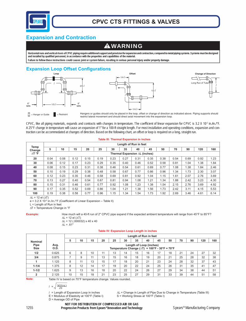
Expansion and Contraction
Expansion Loop Offset Confi gurations
Hangers or guides should only be placed in the loop, offset or change of direction as indicated above. Piping supports should restrict lateral movement and should direct axial movement into the expansion loop.
CPVC, like all piping materials, expands and contracts with changes in temperature. The coeffi cient of linear expansion for CPVC is 3.2 X 10⁻⁵ in./in./°F. A 25°F change in temperature will cause an expansion of 1” for a 100-ft straight length. For most installation and operating conditions, expansion and con-traction can be accommodated at changes of direction. Based on the following chart, an offset or loop is required on a long, straight run.
TempChange∆T °F
Length of Run in feet 5 10 15 20 25 30 35 40 45 50 70 90 120 160
Thermal Expansion ∆L (inches)20 0.04 0.08 0.12 0.15 0.19 0.23 0.27 0.31 0.35 0.38 0.54 0.69 0.92 1.2330 0.06 0.12 0.17 0.23 0.29 0.35 0.40 0.46 0.52 0.58 0.81 1.04 1.38 1.8440 0.08 0.15 0.23 0.31 0.38 0.46 0.54 0.61 0.69 0.77 1.08 1.38 1.84 2.4650 0.10 0.19 0.29 0.38 0.48 0.58 0.67 0.77 0.86 0.96 1.34 1.73 2.30 3.0760 0.12 0.23 0.35 0.46 0.58 0.69 0.81 0.92 1.04 1.15 1.61 2.07 2.76 3.6970 0.13 0.27 0.40 0.54 0.67 0.81 0.94 1.08 1.21 1.34 1.88 2.42 3.23 4.3080 0.15 0.31 0.46 0.61 0.77 0.92 1.08 1.23 1.38 1.54 2.15 2.76 3.69 4.9290 0.17 0.35 0.52 0.69 0.86 1.04 1.21 1.38 1.56 1.73 2.42 3.11 4.15 5.53
100 0.19 0.38 0.58 0.77 0.96 1.15 1.34 1.54 1.73 1.92 2.69 3.46 4.61 6.14
Table III: Thermal Expansion in inches
NominalPipeSize
Avg.O.D.
Length of Run in feet5 10 15 20 25 30 35 40 45 50 70 90 120 160
Length of Loop (inches)Temperature Change (∆T) = 100°F - 30°F = 70°F
1/2 0.625 6 8 10 11 13 14 15 16 17 18 21 24 27 323/4 0.875 7 9 11 13 15 16 18 19 20 21 25 28 32 381 1.125 8 11 13 15 17 18 20 21 23 24 28 32 37 43
1-1/4 1.375 8 12 14 17 19 20 22 24 25 26 31 35 41 471-1/2 1.625 9 13 16 18 20 22 24 26 27 29 34 38 44 51
2 2.125 10 15 18 21 23 25 27 29 31 33 39 44 51 58
Table IV: Expansion Loop Length in inches
∆L = 12 el (∆T)e = 3.2 X 10⁻⁵ in./in./°F (Coeffi cient of Linear Expansion – Table II)L = Length of Run in feet∆T = Temperature Change in °F
Example: How much will a 40-ft run of 2" CPVC pipe expand if the expected ambient temperature will range from 45°F to 85°F?∆L = 12 el (∆T)∆L = 12 (.000032) x 40 x 40∆L = .61"
Note: Table IV is based on 70°F temperature change. Values rounded.
l = 3ED(∆L) 2S
l = Length of Expansion Loop in inches ∆L = Change in Length of Pipe Due to Change in Temperature (Table III)E = Modulus of Elasticity at 100°F (Table I) S = Working Stress at 100°F (Table I)D = Average OD of Pipe
WARNINGHorizontal runs and vertical risers of CPVC piping require additional support and provision for expansion and contraction, compared to metal piping systems. Systems must be designed and installed by qualifi ed personnel, in accordance with the properties and capabilities of the material.Failure to follow these instructions could causes joint or system failure, resulting in serious personal injury and/or property damage.
Made in the U.S.A. 1256
CPVC CTS FITTINGS & VALVES
NOT FOR DISTRIBUTION OF COMPRESSED AIR OR GASProgressive Products from Spears® Innovation and Technology
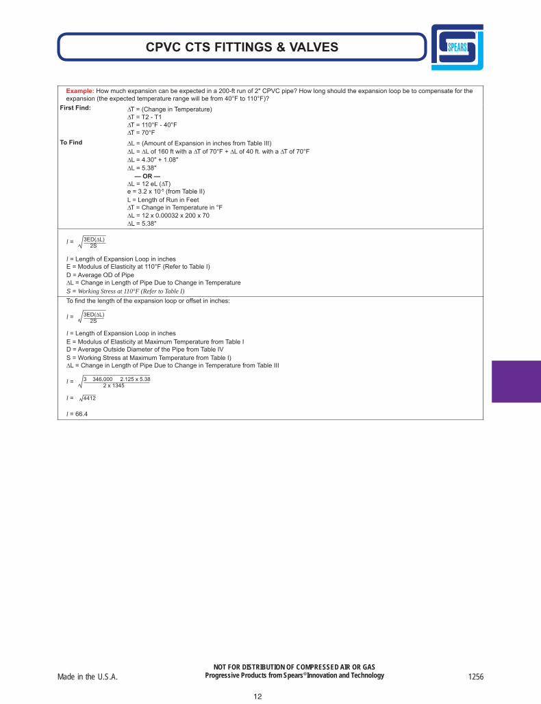
Example: How much expansion can be expected in a 200-ft run of 2" CPVC pipe? How long should the expansion loop be to compensate for the expansion (the expected temperature range will be from 40°F to 110°F)?
First Find:
To Find
∆T = (Change in Temperature)∆T = T2 - T1∆T = 110°F - 40°F∆T = 70°F
∆L = (Amount of Expansion in inches from Table III)∆L = ∆L of 160 ft with a ∆T of 70°F + ∆L of 40 ft. with a ∆T of 70°F∆L = 4.30" + 1.08"∆L = 5.38" — OR —∆L = 12 eL (∆T)e = 3.2 x 10⁻⁵ (from Table II)L = Length of Run in Feet∆T = Change in Temperature in °F∆L = 12 x 0.00032 x 200 x 70∆L = 5.38"
l = 3ED(∆L) 2S
l = Length of Expansion Loop in inchesE = Modulus of Elasticity at 110°F (Refer to Table I)D = Average OD of Pipe∆L = Change in Length of Pipe Due to Change in TemperatureS = Working Stress at 110°F (Refer to Table I)
To find the length of the expansion loop or offset in inches:
l = 3ED(∆L) 2S
l = Length of Expansion Loop in inchesE = Modulus of Elasticity at Maximum Temperature from Table ID = Average Outside Diameter of the Pipe from Table IVS = Working Stress at Maximum Temperature from Table I)∆L = Change in Length of Pipe Due to Change in Temperature from Table III
l = 3 346,000 2.125 x 5.38 2 x 1345
l = 4412
l = 66.4
12
1257 Spears® Manufacturing Company
CPVC CTS FITTINGS & VALVES
NOT FOR DISTRIBUTION OF COMPRESSED AIR OR GASProgressive Products from Spears® Innovation and Technology
CPVC Piping System Guidelinesfor Commercial Hot & Cold Water Distribution Applications
EverTUFF® CPVC Systems provide highly sustainable, cost effective alternatives to metal piping in commercial multi-story applications for hot and cold water distribution. EverTUFF® CPVC pipe and fi ttings are available for most any size project using Copper Tube Size (CTS) CPVC in sizes 1/2" through 2" and in supplemental Schedule 40 and Schedule 80 CPVC Iron Pipe Size (IPS) for sizes 2-1/2" through 12". EverTUFF® CPVC Systems meet applicable code requirements and are fully suitable for use in multi-story installations where adequate design and installation practices have been utilized. The following overview includes, but is not limited to, general considerations that must be addressed in all CPVC system designs and installations.WARNING: Failure to follow proper industry established design and installation practices and requirements for CPVC systems may result in system failure, severe personal injury and/or property damage. The following are general guidelines for issues that must be addressed with use of CPVC in commercial water distribution systems. All design criteria applicable to thermoplastics should be reviewed and approved by a licensed engineering professional.
Product Capability & RatingsEverTUFF® CPVC CTS piping is produced in Standard Dimensional Ratio (SDR) of 11, where the ratio of wall thickness to outside diameter of the pipe is a constant of 11. This produces the same pressure rating for all sizes.Available Sizes: 1/2", 3/4", 1", 1-1/4", 1-1/2", 2"Pressure Rating: 100 psi @ 180°FApplicable Standard: ASTM D 2846 for CPVC Copper Tube Size (CTS) Hot & Cold Water Distribution SystemsPotable Water Certifi cation: ANSI/NSF® Standard 61EverTUFF® Industrial CPVC IPS piping produced in Schedule 40 or Schedule 80 dimensions can be used for larger pipe sizes. Pressure ratings will vary according to diameter and water temperature. The appropriate Schedule piping (40 or 80) must be selected according to application and system requirements.Supplemental Available Sizes: 2-1/2", 3", 4", 6", 8", 10", 12"Pressure Ratings: According to pipe size and temperature; specifi ed in ASTM F 441Applicable Standard: Pipe - ASTM F 441 for CPVC Schedule 40 & Schedule 80 Pipe Fittings – ASTM F 439 for CPVC Schedule 80 FittingsPotable Water Certifi cation: ANSI/NSF® Standard 61Piping Support & SpacingHanger and support spacing for horizontal runs of Spears® EverTUFF® CPVC piping varies according to pipe diameter and water temperature. Local code requirements generally affect minimum spacing for CPVC piping and must be verifi ed. Additional support should be provided for valves, fl anges, expansion joints or other sources of load concentration. Hangers and straps designed for CPVC should be used, but some hangers designed for steel pipe can be used if suitable. Use only smooth straps or hangers that do not place rough or sharp edges against the pipe. Do not anchor CPVC piping too tight to supports in order to allow movement caused by expansion and contraction, bind or restrict movement. Vertical runs (risers) must be properly supported to prevent excessive loading on the lower fi tting or other stress concentration areas. Maintain vertical piping in straight alignment with supports at each floor level, or at 10 feet (3.05 m) intervals, whichever is less. Hangers and clamps suitable for this purpose include riser clamps or double bolt type clamps that provide a fl oating system which allows pipe movement due to thermal expansion and contraction when installed. Clamps and hangers must not compress, distort, cut, abrade or exert compressive stresses on the pipe; the use of riser clamps that utilize compression to support the pipe weight are not recommended.Wall PenetrationWhere Spears® EverTUFF® CPVC pipe passes through metal studs, protection must be used to prevent abrasion and reduce noise. Plastic insulators, rubber grommets, pipe insulation or similar devices may be used for this purpose.Where penetrations of fi re barriers are required, Spears® EverTUFF® CPVC piping can be used with Fire–Stop penetration sealing systems approved for use with CPVC. Most codes accept penetration sealing systems or devices that are UL Listed or have passed the appropriate ASTM E 119 or E 84 tests. Before starting an installation, always consult the building codes and local authority having jurisdiction.Thermal Expansion & ContractionExpansion and contraction in CPVC thermoplastic systems differs signifi cantly from that of metal systems and can result in major problems if not adequately considered. Spears® EverTUFF® CPVC piping will expand or contract about 1 inch per 50 feet of length with a 50-degree temperature change. This movement must be accommodated in system design or else a system can literally push or pull itself apart. Thermal expansion is a primary concern in hot water lines. Expansion and contraction expectations must be calculated according to standard industry practices. For most installation and operating conditions, movement accommodation can be made at system changes of direction, through use of use of telescoping expansion joints, an offset or loop on a long straight runs. Telescoping expansion joint needs must be properly calculated and the telescoping units properly aligned and installed. While only one properly sized expansion loop is required in any straight run, two or more properly sized smaller expan-sion loops can be used to conserve space as required.
Made in the U.S.A. 1258
CPVC CTS FITTINGS & VALVES
NOT FOR DISTRIBUTION OF COMPRESSED AIR OR GASProgressive Products from Spears® Innovation and Technology
Hydraulic Design Spears® EverTUFF® CPVC piping systems must be sized based on industry standard hydraulic calculations for factors such a friction loss and fl ow velocity. Surge protection must also be considered.Friction loss through CPVC pipe is typically determined by the use of the Hazen-Williams equations with a C Factor (internal roughness) of 150. Friction loss and fl ow velocity tables are also available for both CTS CPVC and Schedule 40 or Schedule 80 IPS CPVC piping.While hot and cold water CTS CPVC systems can operate with fl ow velocities of 8 feet per second. A maximum velocity of 5 feet per second is recommended for Schedule 40 or Schedule 80 IPS CPVC systems. System flow velocity should always be maintained close to 5 feet per second in mixed CTS/IPS CPVC systems. Hydraulic designs, and value engineered changes should always be reviewed by a li-censed engineering professional.System ConnectionsProper system connections are critical to maintaining system integrity and reliability. It is essential that all installation personnel be thoroughly trained in joining methods.Solvent Cement Joints are the primary method of making connections between CPVC components. Solvent cements specifi cally approved to ASTM F 493 for CPVC and for use with ASTM D 2846 systems should be used on CTS CPVC installations. ASTM Standards permit the use of “One-step” (primerless) cements; however, local codes must be checked since some require use of both a primer and cement in CPVC joints. Larger Schedule 40 or Schedule 80 IPS joints should be made using an ASTM F 493 approved CPVC cement and primer. Manufac-turer’s instructions for cement/primer application, initial set times and applicable cure time in accordance with pipe size and temperature must be followed. Proper sized cement applicators should always be utilized (i.e., no less than 1/2 the pipe diameter). On 6” and larger IPS pipe come-alongs or other mechanical helpers are recommended to assist in joint assembly.Threaded Transitions to metal systems must be made with appropriate fi ttings designed for plastic-to-metal connections. Spears® offers a variety of transition fi ttings including metal threaded adapter and the superior Special Reinforced (SR) Female Plastic Thread fi ttings for the best transition joints.The chemical compatibility of any thread sealant, pastes, or lubricants with CPVC must be verifi ed. Spears® recommends the use of Spears® Blue 75™ Thread Sealant that has been tested for compatibility. If TFE sealant tape is used, it must be selected and applied correctly, ac-cording to manufacturer’s instructions.Flanged Connection can be used when properly assembled; a full-faced 1/8” thick elastomer gasket must be used. Flange alignment and system support is critical to prevent adverse stress loads. Flange bolts must NEVER be used to draw a fl anged system connection together. Flange bolts, nuts, and washers must be properly selected and incrementally tightened in sequence to torque according to fl ange manufac-turer’s specifi cations. Thermoplastic fl anges are typically rated at 150 psi for water at 73°F and must be de-rated for systems operating at elevated temperatures (i.e., hot water lines).Hot Water Heater & Boiler ConnectionsConnection of CPVC CTS systems to hot water heaters must be made in accordance with code requirements. Typically, 6” metal nipples are required for direct connection to tanks, but approved CPVC CTS piping can be used for connection to temperature/pressure relief valves. Schedule 80 IPS CPVC Boiler Connections generally should not be made directly to the boiler. Most boilers do not have suitable temperature variation control. Connections must assure that the temperature-pressure does not exceed the capability of the CPVC material.System Pressure TestingHydrostatic pressure testing should commence only after all set and cure times for solvent cemented joints have been satisfi ed. The system should be pressure tested in accordance with local code requirements following industry accepted practices for thermoplastic systems.Under slab installations that contain joints must be pressure tested before pouring the slab. NOTE: IAPMO IS 2098, “Installation Standard for CPVC Solvent Cemented Hot and Cold Water Distribution Systems,” requires a test at 150 psi for 2 hours.In freezing temperatures the system should be adequately purged of water after testing to avoid damage from freezing.
1259 Spears® Manufacturing Company
CPVC CTS FITTINGS & VALVES
NOT FOR DISTRIBUTION OF COMPRESSED AIR OR GASProgressive Products from Spears® Innovation and Technology
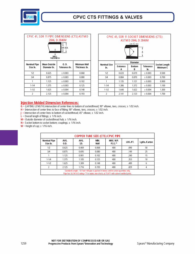
CPVC 41, SDR 11 SOCKET DIMENSIONS (CTS) ASTM D 2846, D 2846M
A
C
B
Nominal SizeIn.
DiameterSocket Length
Minimum CEntranceA
BottomB
ToleranceIn.
1/2 0.633 0.619 ± 0.003 0.5003/4 0.884 0.870 ± 0.003 0.7001 1.135 1.121 ± 0.003 0.900
1-1/4 1.386 1.372 ± 0.003 1.1001-1/2 1.640 1.622 ± 0.004 1.300
2 2.141 2.123 ± 0.004 1.700
CPVC 41, SDR 11 PIPE DIMENSIONS (CTS) ASTM D 2846, D 2846M
WALLTHICKNESS
I.D. O.D.
Nominal Pipe Size In.
Mean Outside Diameter In.
O. D. Tolerance In.
Minimum WallThickness In.
1/2 0.625 ± 0.003 0.0683/4 0.875 ± 0.003 0.0801 1.125 ± 0.003 0.102
1-1/4 1.375 ± 0.003 0.1251-1/2 1.625 ± 0.004 0.148
2 2.125 ± 0.004 0.193
COPPER TUBE SIZE (CTS) CPVC PIPE Nominal Pipe
Size In. AVG. O.D.
AVG.I.D.
MIN.Wall
MAX. W.P.P.S.I. * LBS./FT. Lgths./Carton
1/2 0.625 0.469 0.068 400 .090 503/4 0.875 0.695 0.080 400 .149 251 1.125 0.901 0.102 400 .240 15
1-1/4 1.375 1.105 0.125 400 .353 101-1/2 1.625 1.309 0.148 400 .489 6
2 2.125 1.716 0.193 400 .829 4Standard Length - 10 Feet • All pipe is packed in boxes sold in carton quantities only.
Pipe has UL 94 V-O rating • * For water, non shock, at 73.4°F with solvent welded joints.
Injection Molded Dimension References:G = (LAYING LENGTH) intersection of center lines to bottom of socket/thread; 90° elbows, tees, crosses; ± 1/32 inch. H = Intersection of center lines to face of fitting; 90° elbows, tees, crosses; ± 1/32 inch.J = Intersection of center lines to bottom of socket/thread; 45° elbows; ± 1/32 inch.L = Overall length of fittings; ± 1/16 inch.M = Outside diameter of socket/thread hub; ± 1/16 inch.N = Socket bottom to socket bottom; couplings; ± 1/16 inch.W = Height of cap; ± 1/16 inch.
Made in the U.S.A. 1260
CPVC CTS FITTINGS & VALVES
NOT FOR DISTRIBUTION OF COMPRESSED AIR OR GASProgressive Products from Spears® Innovation and Technology
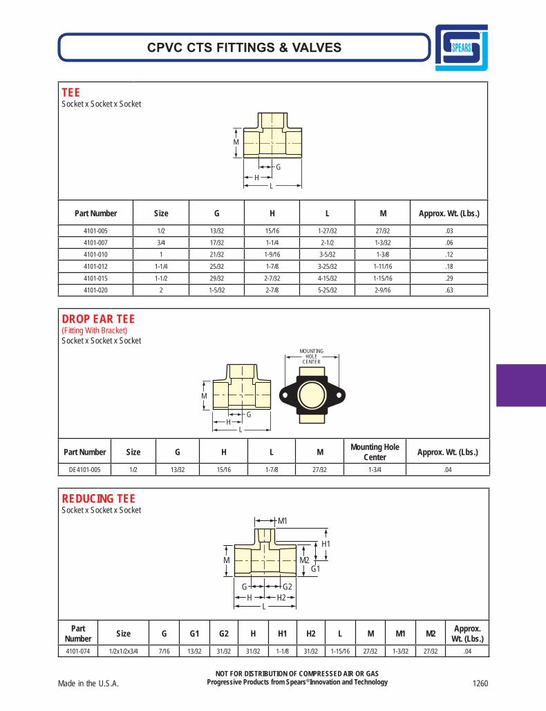
TEE Socket x Socket x Socket
M
HG
L
Part Number Size G H L M Approx. Wt. (Lbs.)
4101-005 1/2 13/32 15/16 1-27/32 27/32 .034101-007 3/4 17/32 1-1/4 2-1/2 1-3/32 .064101-010 1 21/32 1-9/16 3-5/32 1-3/8 .12
4101-012 1-1/4 25/32 1-7/8 3-25/32 1-11/16 .18
4101-015 1-1/2 29/32 2-7/32 4-15/32 1-15/16 .294101-020 2 1-5/32 2-7/8 5-25/32 2-9/16 .63
DROP EAR TEE(Fitting With Bracket)Socket x Socket x Socket
MOUNTING HOLE
CENTER
M
L H
G
Part Number Size G H L M Mounting Hole Center Approx. Wt. (Lbs.)
DE4101-005 1/2 13/32 15/16 1-7/8 27/32 1-3/4 .04
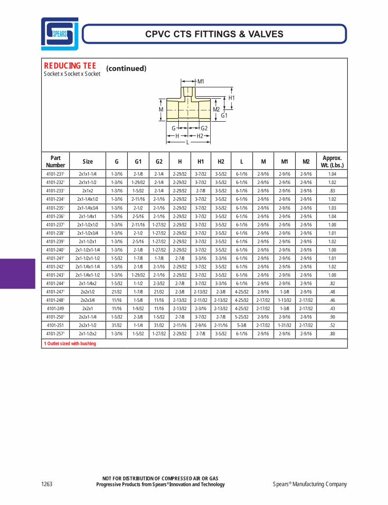
REDUCING TEESocket x Socket x Socket
M
H1
H H2 G G2
L
G1 M2
M1
Part Number Size G G1 G2 H H1 H2 L M M1 M2 Approx.
Wt. (Lbs.)4101-074 1/2x1/2x3/4 7/16 13/32 31/32 31/32 1-1/8 31/32 1-15/16 27/32 1-3/32 27/32 .04

1261 Spears® Manufacturing Company
CPVC CTS FITTINGS & VALVES
NOT FOR DISTRIBUTION OF COMPRESSED AIR OR GASProgressive Products from Spears® Innovation and Technology
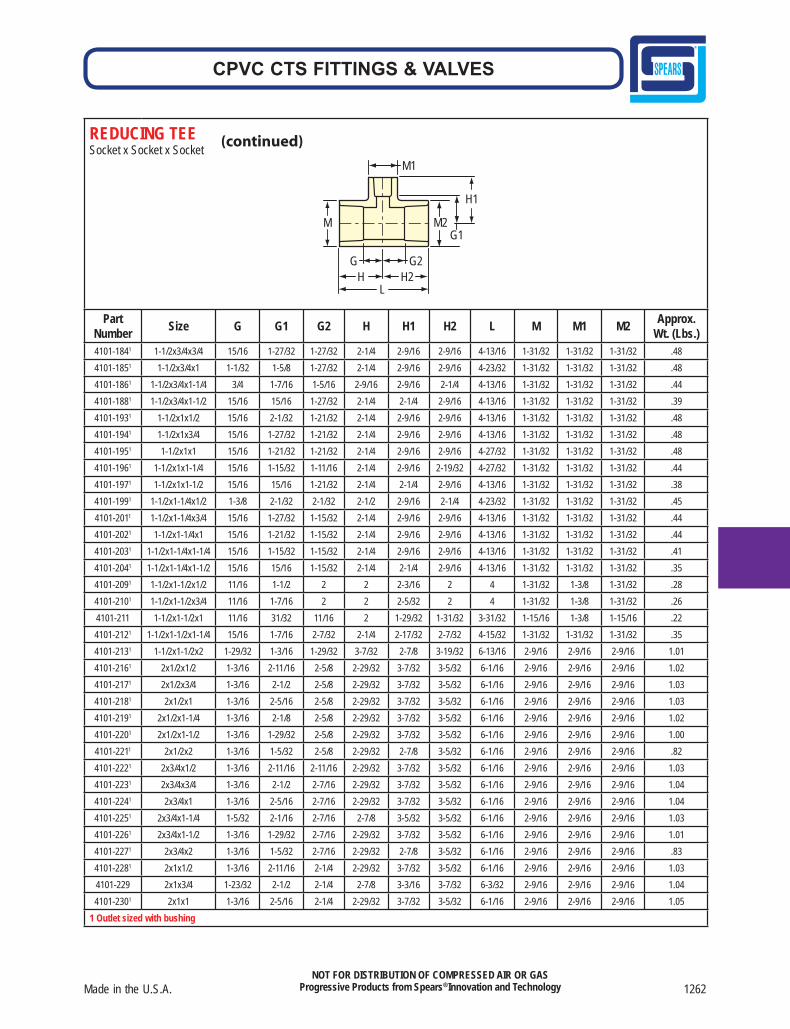
REDUCING TEESocket x Socket x Socket
M
H1
H H2 G G2
L
G1 M2
M1
Part Number Size G G1 G2 H H1 H2 L M M1 M2 Approx.
Wt. (Lbs.)4101-094 3/4x1/2x1/2 7/16 17/32 7/16 1-5/32 1-1/32 31/32 2-1/8 1-3/32 27/32 27/32 .054101-095 3/4x1/2x3/4 1/2 17/32 19/32 1-7/32 1-1/4 1-1/8 2-11/32 1-3/32 1-3/32 27/32 .06
4101-101 3/4x3/4x1/2 13/32 17/32 13/32 1-1/8 1-1/32 1-1/8 2-1/4 1-3/32 7/8 1-3/32 .05
4101-1021 3/4x3/4x1 1-1/8 11/16 1-13/16 1-27/32 1-19/32 1-13/16 3-21/32 1-11/32 1-11/32 1-11/32 .164101-1201 1x1/2x1/2 11/16 1-5/16 1-1/4 1-19/32 1-27/32 1-25/32 3-3/8 1-11/32 1-11/32 1-11/32 .204101-1211 1x1/2x3/4 11/16 1-1/8 1-1/4 1-19/32 1-27/32 1-25/32 3-3/8 1-11/32 1-11/32 1-11/32 .184101-1221 1x1/2x1 11/16 11/16 1-1/4 1-19/32 1-19/32 1-25/32 3-3/8 1-11/32 1-11/32 1-11/32 .154101-1241 1x3/4x1/2 11/16 1-5/16 1-1/16 1-19/32 1-27/32 1-25/32 3-3/8 1-11/32 1-11/32 1-11/32 .184101-125 1x3/4x3/4 17/32 11/16 17/32 1-15/32 1-13/32 1-1/4 2-23/32 1-11/32 1-3/32 1-3/32 .084101-1261 1x3/4x1 11/16 15/16 1-1/16 1-19/32 1-27/32 1-25/32 3-3/8 1-11/32 1-11/32 1-11/32 .134101-130 1x1x1/2 13/32 11/16 13/32 1-11/32 1-7/32 1-11/32 2-21/32 1-3/8 7/8 1-3/8 .074101-131 1x1x3/4 9/16 11/16 9/16 1-15/32 1-13/32 1-15/32 2-15/16 1-3/8 1-3/32 1-3/8 .094101-1381 1-1/4x1/2x1/2 13/16 1-11/16 1-21/32 1-29/32 2-7/32 2-3/16 4-3/32 1-21/32 1-21/32 1-21/32 .304101-1391 1-1/4x1/2x3/4 13/16 1-1/2 1-21/32 1-29/32 2-7/32 2-3/16 4-3/32 1-21/32 1-21/32 1-21/32 .304101-1421 1-1/4x1/2x1-1/4 13/16 27/32 1-21/32 1-29/32 1-15/16 2-3/16 4-3/32 1-21/32 1-21/32 1-21/32 .244101-1461 1-1/4x3/4x1/2 13/16 1-11/16 1-15/32 1-29/32 2-7/32 2-3/16 4-3/32 1-21/32 1-21/32 1-21/32 .304101-1471 1-1/4x3/4x3/4 13/16 1-1/2 1-15/32 1-29/32 2-7/32 2-3/16 4-3/32 1-21/32 1-21/32 1-21/32 .314101-1481 1-1/4x3/4x1 13/16 1-5/16 1-15/32 1-29/32 2-7/32 2-3/16 4-3/32 1-21/32 1-21/32 1-21/32 .294101-1491 1-1/4x3/4x1-1/4 25/32 25/32 1-7/16 1-29/32 1-29/32 2-3/16 4-3/32 1-21/32 1-21/32 1-21/32 .264101-1561 1-1/4x1x1/2 13/16 1-21/32 1-1/4 1-29/32 2-3/16 2-5/32 4-1/16 1-21/32 1-21/32 1-21/32 .304101-1571 1-1/4x1x3/4 13/16 1-1/2 1-9/32 1-29/32 2-7/32 2-3/16 4-3/32 1-21/32 1-21/32 1-21/32 .294101-1581 1-1/4x1x1 13/16 1-5/16 1-9/32 1-29/32 2-7/32 2-3/16 4-3/32 1-21/32 1-21/32 1-21/32 .274101-1591 1-1/4x1x1-1/4 13/16 27/32 1-9/32 1-29/32 1-15/16 2-3/16 4-3/32 1-21/32 1-21/32 1-21/32 .224101-166 1-1/4x1-1/4x1/2 11/32 27/32 13/32 1-17/32 1-11/32 1-17/32 3-9/16 1-21/32 7/8 1-21/32 .124101-167 1-1/4x1-1/4x3/4 17/32 13/16 17/32 1-21/32 1-17/32 1-21/32 3-5/16 1-21/32 1-1/8 1-21/32 .134101-168 1-1/4x1-1/4x1 11/16 13/16 11/16 1-25/32 1-3/4 1-25/32 3-19/32 1-21/32 1-3/8 1-21/32 .154101-1691 1-1/4x1-1/4x1-1/2 1-7/16 15/16 2-1/32 2-17/32 2-1/4 2-17/32 5-1/16 1-31/32 1-31/32 1-31/32 .414101-1731 1-1/2x1/2x1/2 15/16 2-1/32 2-1/32 2-1/4 2-9/16 2-9/16 4-13/16 1-31/32 1-31/32 1-31/32 .494101-1741 1-1/2x1/2x3/4 15/16 1-27/32 2-1/32 2-1/4 2-9/16 2-9/16 4-13/16 1-31/32 1-31/32 1-31/32 .494101-1751 1-1/2x1/2x1 11/16 1 1-13/16 2 1-29/32 2-11/32 4-11/32 1-31/32 1-3/8 1-31/32 .484101-1761 1-1/2x1/2x1-1/4 15/16 1-15/32 2-1/32 2-1/4 2-9/16 2-9/16 4-13/16 1-31/32 1-31/32 1-31/32 .454101-1771 1-1/2x1/2x1-1/2 15/16 15/16 2-1/32 2-1/4 2-1/4 2-9/16 4-13/16 1-31/32 1-31/32 1-31/32 .394101-1821 1-1/2x3/4x1/2 15/16 2-1/32 1-27/32 2-1/4 2-9/16 2-9/16 4-13/16 1-31/32 1-31/32 1-31/32 .49
1 Outlet sized with bushing
Made in the U.S.A. 1262
CPVC CTS FITTINGS & VALVES
NOT FOR DISTRIBUTION OF COMPRESSED AIR OR GASProgressive Products from Spears® Innovation and Technology
REDUCING TEESocket x Socket x Socket
M
H1
H H2 G G2
L
G1 M2
M1
Part Number Size G G1 G2 H H1 H2 L M M1 M2 Approx.
Wt. (Lbs.)4101-1841 1-1/2x3/4x3/4 15/16 1-27/32 1-27/32 2-1/4 2-9/16 2-9/16 4-13/16 1-31/32 1-31/32 1-31/32 .484101-1851 1-1/2x3/4x1 1-1/32 1-5/8 1-27/32 2-1/4 2-9/16 2-9/16 4-23/32 1-31/32 1-31/32 1-31/32 .484101-1861 1-1/2x3/4x1-1/4 3/4 1-7/16 1-5/16 2-9/16 2-9/16 2-1/4 4-13/16 1-31/32 1-31/32 1-31/32 .444101-1881 1-1/2x3/4x1-1/2 15/16 15/16 1-27/32 2-1/4 2-1/4 2-9/16 4-13/16 1-31/32 1-31/32 1-31/32 .394101-1931 1-1/2x1x1/2 15/16 2-1/32 1-21/32 2-1/4 2-9/16 2-9/16 4-13/16 1-31/32 1-31/32 1-31/32 .484101-1941 1-1/2x1x3/4 15/16 1-27/32 1-21/32 2-1/4 2-9/16 2-9/16 4-13/16 1-31/32 1-31/32 1-31/32 .484101-1951 1-1/2x1x1 15/16 1-21/32 1-21/32 2-1/4 2-9/16 2-9/16 4-27/32 1-31/32 1-31/32 1-31/32 .484101-1961 1-1/2x1x1-1/4 15/16 1-15/32 1-11/16 2-1/4 2-9/16 2-19/32 4-27/32 1-31/32 1-31/32 1-31/32 .444101-1971 1-1/2x1x1-1/2 15/16 15/16 1-21/32 2-1/4 2-1/4 2-9/16 4-13/16 1-31/32 1-31/32 1-31/32 .384101-1991 1-1/2x1-1/4x1/2 1-3/8 2-1/32 2-1/32 2-1/2 2-9/16 2-1/4 4-23/32 1-31/32 1-31/32 1-31/32 .454101-2011 1-1/2x1-1/4x3/4 15/16 1-27/32 1-15/32 2-1/4 2-9/16 2-9/16 4-13/16 1-31/32 1-31/32 1-31/32 .444101-2021 1-1/2x1-1/4x1 15/16 1-21/32 1-15/32 2-1/4 2-9/16 2-9/16 4-13/16 1-31/32 1-31/32 1-31/32 .444101-2031 1-1/2x1-1/4x1-1/4 15/16 1-15/32 1-15/32 2-1/4 2-9/16 2-9/16 4-13/16 1-31/32 1-31/32 1-31/32 .414101-2041 1-1/2x1-1/4x1-1/2 15/16 15/16 1-15/32 2-1/4 2-1/4 2-9/16 4-13/16 1-31/32 1-31/32 1-31/32 .354101-2091 1-1/2x1-1/2x1/2 11/16 1-1/2 2 2 2-3/16 2 4 1-31/32 1-3/8 1-31/32 .284101-2101 1-1/2x1-1/2x3/4 11/16 1-7/16 2 2 2-5/32 2 4 1-31/32 1-3/8 1-31/32 .264101-211 1-1/2x1-1/2x1 11/16 31/32 11/16 2 1-29/32 1-31/32 3-31/32 1-15/16 1-3/8 1-15/16 .224101-2121 1-1/2x1-1/2x1-1/4 15/16 1-7/16 2-7/32 2-1/4 2-17/32 2-7/32 4-15/32 1-31/32 1-31/32 1-31/32 .354101-2131 1-1/2x1-1/2x2 1-29/32 1-3/16 1-29/32 3-7/32 2-7/8 3-19/32 6-13/16 2-9/16 2-9/16 2-9/16 1.014101-2161 2x1/2x1/2 1-3/16 2-11/16 2-5/8 2-29/32 3-7/32 3-5/32 6-1/16 2-9/16 2-9/16 2-9/16 1.024101-2171 2x1/2x3/4 1-3/16 2-1/2 2-5/8 2-29/32 3-7/32 3-5/32 6-1/16 2-9/16 2-9/16 2-9/16 1.034101-2181 2x1/2x1 1-3/16 2-5/16 2-5/8 2-29/32 3-7/32 3-5/32 6-1/16 2-9/16 2-9/16 2-9/16 1.034101-2191 2x1/2x1-1/4 1-3/16 2-1/8 2-5/8 2-29/32 3-7/32 3-5/32 6-1/16 2-9/16 2-9/16 2-9/16 1.024101-2201 2x1/2x1-1/2 1-3/16 1-29/32 2-5/8 2-29/32 3-7/32 3-5/32 6-1/16 2-9/16 2-9/16 2-9/16 1.004101-2211 2x1/2x2 1-3/16 1-5/32 2-5/8 2-29/32 2-7/8 3-5/32 6-1/16 2-9/16 2-9/16 2-9/16 .824101-2221 2x3/4x1/2 1-3/16 2-11/16 2-11/16 2-29/32 3-7/32 3-5/32 6-1/16 2-9/16 2-9/16 2-9/16 1.034101-2231 2x3/4x3/4 1-3/16 2-1/2 2-7/16 2-29/32 3-7/32 3-5/32 6-1/16 2-9/16 2-9/16 2-9/16 1.044101-2241 2x3/4x1 1-3/16 2-5/16 2-7/16 2-29/32 3-7/32 3-5/32 6-1/16 2-9/16 2-9/16 2-9/16 1.044101-2251 2x3/4x1-1/4 1-5/32 2-1/16 2-7/16 2-7/8 3-5/32 3-5/32 6-1/16 2-9/16 2-9/16 2-9/16 1.034101-2261 2x3/4x1-1/2 1-3/16 1-29/32 2-7/16 2-29/32 3-7/32 3-5/32 6-1/16 2-9/16 2-9/16 2-9/16 1.014101-2271 2x3/4x2 1-3/16 1-5/32 2-7/16 2-29/32 2-7/8 3-5/32 6-1/16 2-9/16 2-9/16 2-9/16 .834101-2281 2x1x1/2 1-3/16 2-11/16 2-1/4 2-29/32 3-7/32 3-5/32 6-1/16 2-9/16 2-9/16 2-9/16 1.034101-229 2x1x3/4 1-23/32 2-1/2 2-1/4 2-7/8 3-3/16 3-7/32 6-3/32 2-9/16 2-9/16 2-9/16 1.044101-2301 2x1x1 1-3/16 2-5/16 2-1/4 2-29/32 3-7/32 3-5/32 6-1/16 2-9/16 2-9/16 2-9/16 1.05
1 Outlet sized with bushing
1263 Spears® Manufacturing Company
CPVC CTS FITTINGS & VALVES
NOT FOR DISTRIBUTION OF COMPRESSED AIR OR GASProgressive Products from Spears® Innovation and Technology
REDUCING TEESocket x Socket x Socket
M
H1
H H2 G G2
L
G1 M2
M1
Part Number Size G G1 G2 H H1 H2 L M M1 M2 Approx.
Wt. (Lbs.)4101-2311 2x1x1-1/4 1-3/16 2-1/8 2-1/4 2-29/32 3-7/32 3-5/32 6-1/16 2-9/16 2-9/16 2-9/16 1.044101-2321 2x1x1-1/2 1-3/16 1-29/32 2-1/4 2-29/32 3-7/32 3-5/32 6-1/16 2-9/16 2-9/16 2-9/16 1.024101-2331 2x1x2 1-3/16 1-5/32 2-1/4 2-29/32 2-7/8 3-5/32 6-1/16 2-9/16 2-9/16 2-9/16 .834101-2341 2x1-1/4x1/2 1-3/16 2-11/16 2-1/16 2-29/32 3-7/32 3-5/32 6-1/16 2-9/16 2-9/16 2-9/16 1.02
4101-2351 2x1-1/4x3/4 1-3/16 2-1/2 2-1/16 2-29/32 3-7/32 3-5/32 6-1/16 2-9/16 2-9/16 2-9/16 1.034101-2361 2x1-1/4x1 1-3/16 2-5/16 2-1/16 2-29/32 3-7/32 3-5/32 6-1/16 2-9/16 2-9/16 2-9/16 1.044101-2371 2x1-1/2x1/2 1-3/16 2-11/16 1-27/32 2-29/32 3-7/32 3-5/32 6-1/16 2-9/16 2-9/16 2-9/16 1.004101-2381 2x1-1/2x3/4 1-3/16 2-1/2 1-27/32 2-29/32 3-7/32 3-5/32 6-1/16 2-9/16 2-9/16 2-9/16 1.014101-2391 2x1-1/2x1 1-3/16 2-5/16 1-27/32 2-29/32 3-7/32 3-5/32 6-1/16 2-9/16 2-9/16 2-9/16 1.024101-2401 2x1-1/2x1-1/4 1-3/16 2-1/8 1-27/32 2-29/32 3-7/32 3-5/32 6-1/16 2-9/16 2-9/16 2-9/16 1.004101-2411 2x1-1/2x1-1/2 1-5/32 1-7/8 1-7/8 2-7/8 3-3/16 3-3/16 6-1/16 2-9/16 2-9/16 2-9/16 1.014101-2421 2x1-1/4x1-1/4 1-3/16 2-1/8 2-1/16 2-29/32 3-7/32 3-5/32 6-1/16 2-9/16 2-9/16 2-9/16 1.024101-2431 2x1-1/4x1-1/2 1-3/16 1-29/32 2-1/16 2-29/32 3-7/32 3-5/32 6-1/16 2-9/16 2-9/16 2-9/16 1.004101-2441 2x1-1/4x2 1-5/32 1-1/2 2-3/32 2-7/8 3-7/32 3-3/16 6-1/16 2-9/16 2-9/16 2-9/16 .824101-2471 2x2x1/2 21/32 1-7/8 21/32 2-3/8 2-13/32 2-3/8 4-25/32 2-9/16 1-3/8 2-9/16 .484101-2481 2x2x3/4 11/16 1-5/8 11/16 2-13/32 2-11/32 2-13/32 4-25/32 2-17/32 1-13/32 2-17/32 .464101-249 2x2x1 11/16 1-9/32 11/16 2-13/32 2-3/16 2-13/32 4-25/32 2-17/32 1-3/8 2-17/32 .434101-2501 2x2x1-1/4 1-5/32 2-3/8 1-5/32 2-7/8 3-7/32 2-7/8 5-25/32 2-9/16 2-9/16 2-9/16 .904101-251 2x2x1-1/2 31/32 1-1/4 31/32 2-11/16 2-9/16 2-11/16 5-3/8 2-17/32 1-31/32 2-17/32 .524101-2571 2x1-1/2x2 1-3/16 1-5/32 1-27/32 2-29/32 2-7/8 3-5/32 6-1/16 2-9/16 2-9/16 2-9/16 .80
1 Outlet sized with bushing
Made in the U.S.A. 1264
CPVC CTS FITTINGS & VALVES
NOT FOR DISTRIBUTION OF COMPRESSED AIR OR GASProgressive Products from Spears® Innovation and Technology
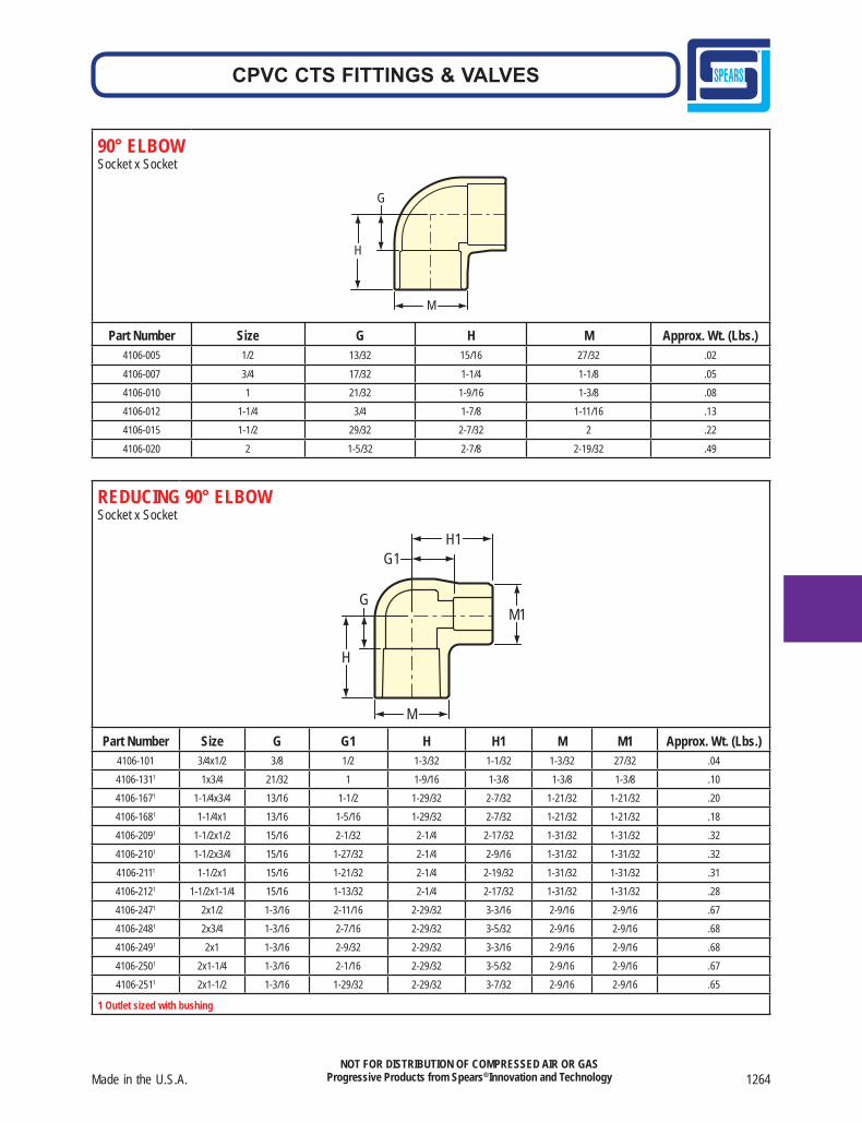
90° ELBOWSocket x Socket
H
M
G
Part Number Size G H M Approx. Wt. (Lbs.)4106-005 1/2 13/32 15/16 27/32 .02
4106-007 3/4 17/32 1-1/4 1-1/8 .054106-010 1 21/32 1-9/16 1-3/8 .084106-012 1-1/4 3/4 1-7/8 1-11/16 .134106-015 1-1/2 29/32 2-7/32 2 .22
4106-020 2 1-5/32 2-7/8 2-19/32 .49
REDUCING 90° ELBOWSocket x Socket
H1 G1
M1
H
G
M
Part Number Size G G1 H H1 M M1 Approx. Wt. (Lbs.)4106-101 3/4x1/2 3/8 1/2 1-3/32 1-1/32 1-3/32 27/32 .044106-1311 1x3/4 21/32 1 1-9/16 1-3/8 1-3/8 1-3/8 .104106-1671 1-1/4x3/4 13/16 1-1/2 1-29/32 2-7/32 1-21/32 1-21/32 .204106-1681 1-1/4x1 13/16 1-5/16 1-29/32 2-7/32 1-21/32 1-21/32 .184106-2091 1-1/2x1/2 15/16 2-1/32 2-1/4 2-17/32 1-31/32 1-31/32 .324106-2101 1-1/2x3/4 15/16 1-27/32 2-1/4 2-9/16 1-31/32 1-31/32 .324106-2111 1-1/2x1 15/16 1-21/32 2-1/4 2-19/32 1-31/32 1-31/32 .314106-2121 1-1/2x1-1/4 15/16 1-13/32 2-1/4 2-17/32 1-31/32 1-31/32 .284106-2471 2x1/2 1-3/16 2-11/16 2-29/32 3-3/16 2-9/16 2-9/16 .674106-2481 2x3/4 1-3/16 2-7/16 2-29/32 3-5/32 2-9/16 2-9/16 .684106-2491 2x1 1-3/16 2-9/32 2-29/32 3-3/16 2-9/16 2-9/16 .684106-2501 2x1-1/4 1-3/16 2-1/16 2-29/32 3-5/32 2-9/16 2-9/16 .674106-2511 2x1-1/2 1-3/16 1-29/32 2-29/32 3-7/32 2-9/16 2-9/16 .65
1 Outlet sized with bushing
1265 Spears® Manufacturing Company
CPVC CTS FITTINGS & VALVES
NOT FOR DISTRIBUTION OF COMPRESSED AIR OR GASProgressive Products from Spears® Innovation and Technology
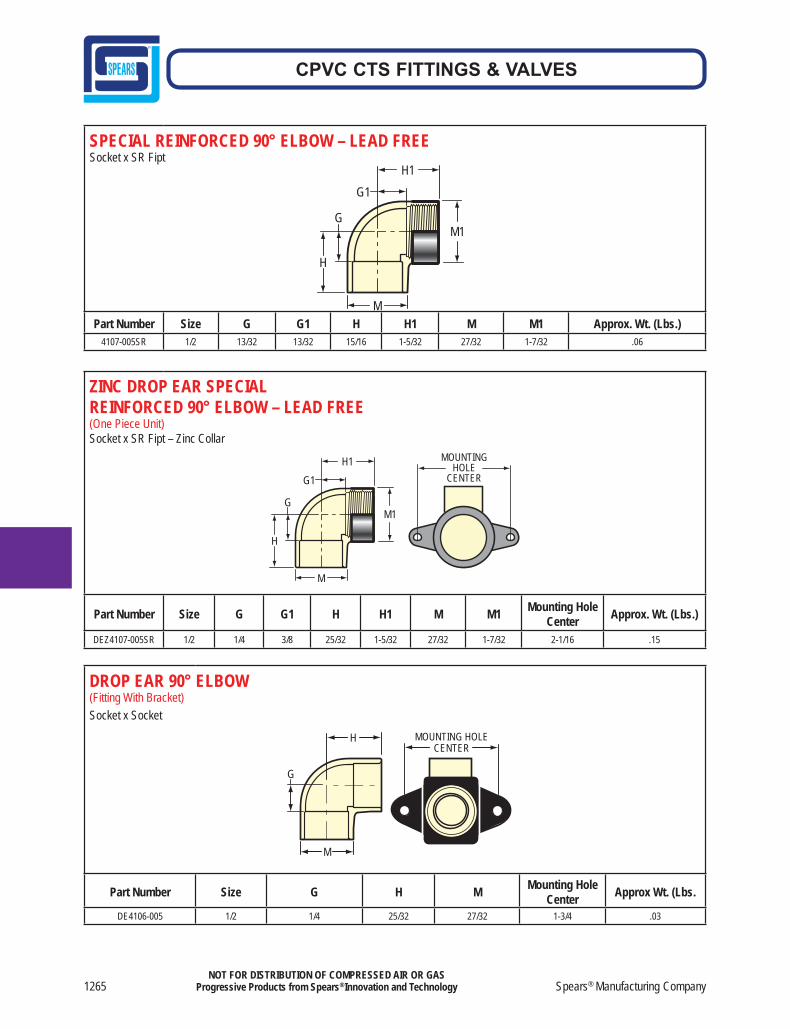
SPECIAL REINFORCED 90° ELBOW – LEAD FREESocket x SR Fipt
H
M
G
H1 G1
M1
Part Number Size G G1 H H1 M M1 Approx. Wt. (Lbs.)4107-005SR 1/2 13/32 13/32 15/16 1-5/32 27/32 1-7/32 .06
ZINC DROP EAR SPECIALREINFORCED 90° ELBOW – LEAD FREE(One Piece Unit) Socket x SR Fipt – Zinc Collar
H
MOUNTING HOLE
CENTER
M
G
H1 G1
M1
Part Number Size G G1 H H1 M M1 Mounting Hole Center Approx. Wt. (Lbs.)
DEZ4107-005SR 1/2 1/4 3/8 25/32 1-5/32 27/32 1-7/32 2-1/16 .15
DROP EAR 90° ELBOW(Fitting With Bracket)Socket x Socket
MOUNTING HOLECENTER
M
G
H
Part Number Size G H M Mounting Hole Center Approx Wt. (Lbs.
DE4106-005 1/2 1/4 25/32 27/32 1-3/4 .03
Made in the U.S.A. 1266
CPVC CTS FITTINGS & VALVES
NOT FOR DISTRIBUTION OF COMPRESSED AIR OR GASProgressive Products from Spears® Innovation and Technology
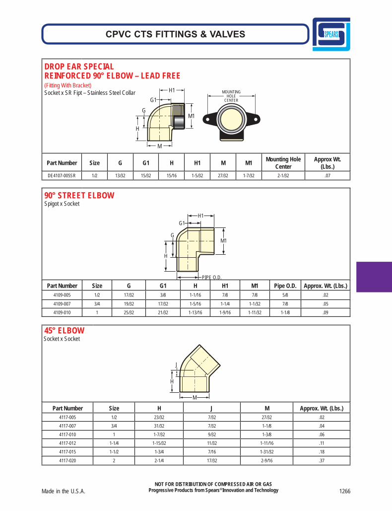
DROP EAR SPECIAL REINFORCED 90° ELBOW – LEAD FREE(Fitting With Bracket)Socket x SR Fipt – Stainless Steel Collar
Part Number Size G G1 H H1 M M1 Mounting Hole Center
Approx Wt. (Lbs.)
DE4107-005SR 1/2 13/32 15/32 15/16 1-5/32 27/32 1-7/32 2-1/32 .07
90° STREET ELBOWSpigot x Socket
PIPE O.D.
H1 G1
G
H
M1
Part Number Size G G1 H H1 M1 Pipe O.D. Approx. Wt. (Lbs.)4109-005 1/2 17/32 3/8 1-1/16 7/8 7/8 5/8 .02
4109-007 3/4 19/32 17/32 1-5/16 1-1/4 1-1/32 7/8 .05
4109-010 1 25/32 21/32 1-13/16 1-9/16 1-11/32 1-1/8 .09
45° ELBOW Socket x Socket
M
H
J
Part Number Size H J M Approx. Wt. (Lbs.)4117-005 1/2 23/32 7/32 27/32 .02
4117-007 3/4 31/32 7/32 1-1/8 .04
4117-010 1 1-7/32 9/32 1-3/8 .06
4117-012 1-1/4 1-15/32 11/32 1-11/16 .11
4117-015 1-1/2 1-3/4 7/16 1-31/32 .18
4117-020 2 2-1/4 17/32 2-9/16 .37
MOUNTINGHOLE
CENTER
H
M
G
H1 G1
M1
1267 Spears® Manufacturing Company
CPVC CTS FITTINGS & VALVES
NOT FOR DISTRIBUTION OF COMPRESSED AIR OR GASProgressive Products from Spears® Innovation and Technology
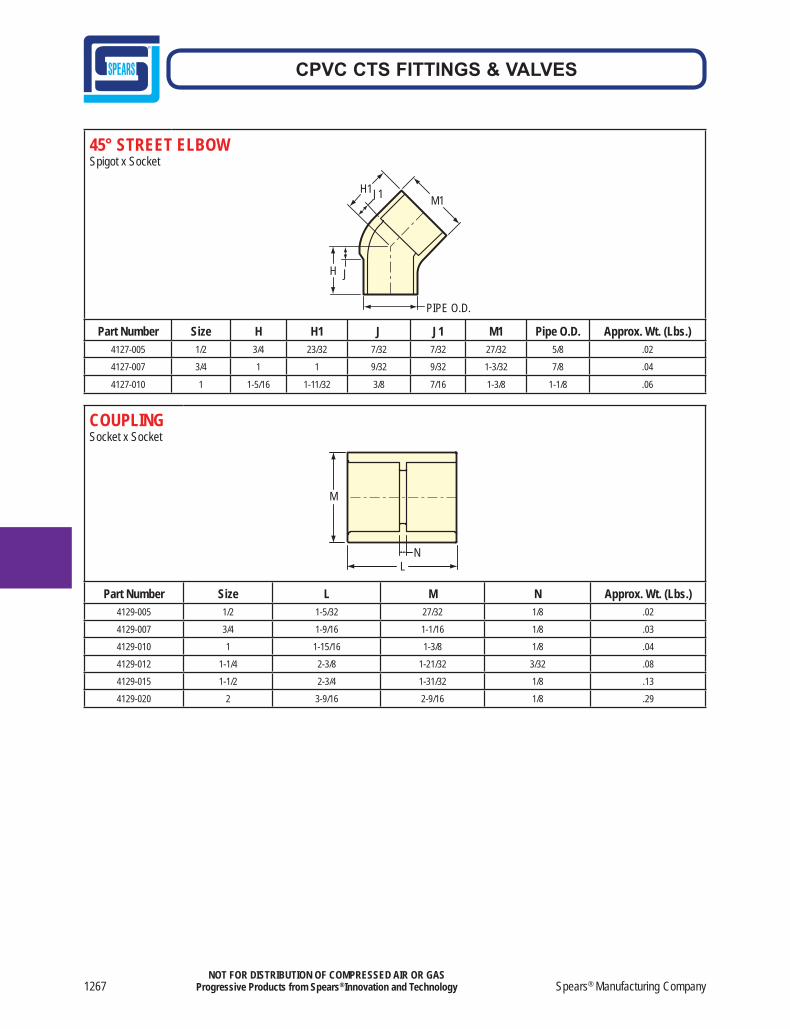
45° STREET ELBOWSpigot x Socket
J1 H1 M1
JH
PIPE O.D.
Part Number Size H H1 J J1 M1 Pipe O.D. Approx. Wt. (Lbs.)4127-005 1/2 3/4 23/32 7/32 7/32 27/32 5/8 .02
4127-007 3/4 1 1 9/32 9/32 1-3/32 7/8 .04
4127-010 1 1-5/16 1-11/32 3/8 7/16 1-3/8 1-1/8 .06
COUPLINGSocket x Socket
M
L N
Part Number Size L M N Approx. Wt. (Lbs.)4129-005 1/2 1-5/32 27/32 1/8 .02
4129-007 3/4 1-9/16 1-1/16 1/8 .03
4129-010 1 1-15/16 1-3/8 1/8 .04
4129-012 1-1/4 2-3/8 1-21/32 3/32 .08
4129-015 1-1/2 2-3/4 1-31/32 1/8 .13
4129-020 2 3-9/16 2-9/16 1/8 .29
Made in the U.S.A. 1268
CPVC CTS FITTINGS & VALVES
NOT FOR DISTRIBUTION OF COMPRESSED AIR OR GASProgressive Products from Spears® Innovation and Technology
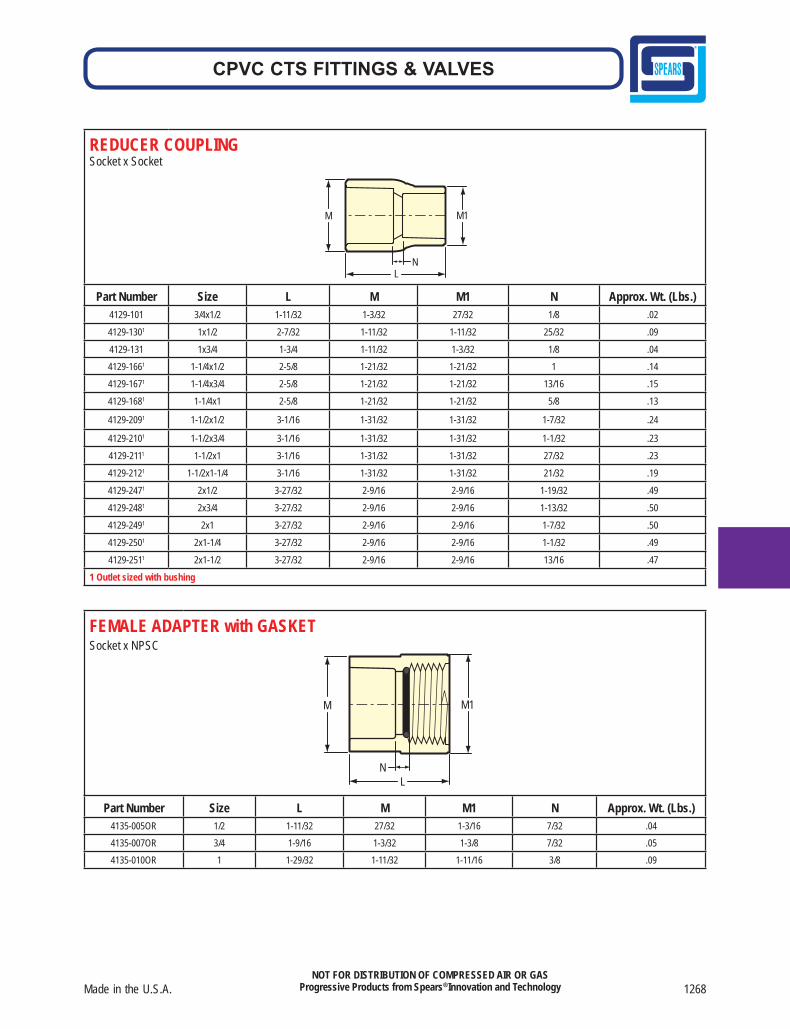
REDUCER COUPLING Socket x Socket
M M1
N L
Part Number Size L M M1 N Approx. Wt. (Lbs.)4129-101 3/4x1/2 1-11/32 1-3/32 27/32 1/8 .02
4129-1301 1x1/2 2-7/32 1-11/32 1-11/32 25/32 .09
4129-131 1x3/4 1-3/4 1-11/32 1-3/32 1/8 .04
4129-1661 1-1/4x1/2 2-5/8 1-21/32 1-21/32 1 .14
4129-1671 1-1/4x3/4 2-5/8 1-21/32 1-21/32 13/16 .15
4129-1681 1-1/4x1 2-5/8 1-21/32 1-21/32 5/8 .13
4129-2091 1-1/2x1/2 3-1/16 1-31/32 1-31/32 1-7/32 .24
4129-2101 1-1/2x3/4 3-1/16 1-31/32 1-31/32 1-1/32 .23
4129-2111 1-1/2x1 3-1/16 1-31/32 1-31/32 27/32 .23
4129-2121 1-1/2x1-1/4 3-1/16 1-31/32 1-31/32 21/32 .19
4129-2471 2x1/2 3-27/32 2-9/16 2-9/16 1-19/32 .49
4129-2481 2x3/4 3-27/32 2-9/16 2-9/16 1-13/32 .50
4129-2491 2x1 3-27/32 2-9/16 2-9/16 1-7/32 .50
4129-2501 2x1-1/4 3-27/32 2-9/16 2-9/16 1-1/32 .49
4129-2511 2x1-1/2 3-27/32 2-9/16 2-9/16 13/16 .47
1 Outlet sized with bushing
FEMALE ADAPTER with GASKETSocket x NPSC
M1 M
L N
Part Number Size L M M1 N Approx. Wt. (Lbs.)4135-005OR 1/2 1-11/32 27/32 1-3/16 7/32 .044135-007OR 3/4 1-9/16 1-3/32 1-3/8 7/32 .054135-010OR 1 1-29/32 1-11/32 1-11/16 3/8 .09
1269 Spears® Manufacturing Company
CPVC CTS FITTINGS & VALVES
NOT FOR DISTRIBUTION OF COMPRESSED AIR OR GASProgressive Products from Spears® Innovation and Technology
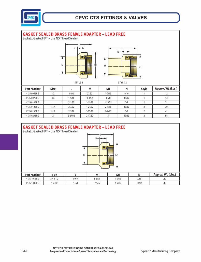
GASKET SEALED BRASS FEMALE ADAPTER – LEAD FREESocket x Gasket FIPT – Use NO Thread Sealant
Part Number Size L M M1 N Style Approx. Wt. (Lbs.)4135-005BRG 1/2 1-1/2 27/32 1-7/16 9/16 1 .12
4135-007BRG 3/4 1-9/16 1-3/32 1-5/8 15/32 1 .13
4135-010BRG 1 2-1/32 1-11/32 1-23/32 5/8 2 .21
4135-012BRG 1-1/4 2-7/32 1-21/32 2-1/16 19/32 2 .30
4135-015BRG 1-1/2 2-7/16 1-15/16 2-7/16 5/8 2 .41
4135-020BRG 2 2-27/32 2-17/32 3 19/32 2 .54
STYLE 1
NL
M1M
STYLE 2
NL
M1M
GASKET SEALED BRASS FEMALE ADAPTER – LEAD FREESocket x Gasket FIPT – Use NO Thread Sealant
Part Number Size L M M1 N Approx. Wt. (Lbs.)4135-101BRG 3/4 x 1/2 1-9/16 1-3/32 1-7/16 7/16 .124135-130BRG 1 x 1/2 1-3/4 1-11/32 1-7/16 13/32 .13
NL
M1M
Made in the U.S.A. 1270
CPVC CTS FITTINGS & VALVES
NOT FOR DISTRIBUTION OF COMPRESSED AIR OR GASProgressive Products from Spears® Innovation and Technology
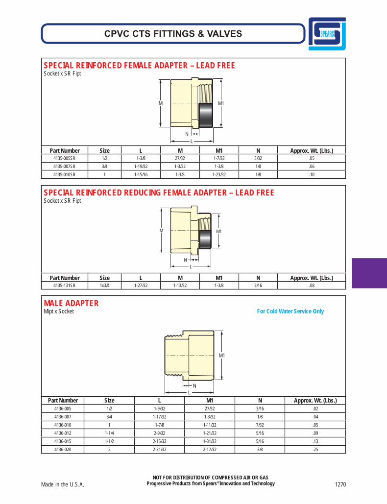
SPECIAL REINFORCED FEMALE ADAPTER – LEAD FREESocket x SR Fipt
M1 M
L N
Part Number Size L M M1 N Approx. Wt. (Lbs.)4135-005SR 1/2 1-3/8 27/32 1-7/32 3/32 .054135-007SR 3/4 1-19/32 1-3/32 1-3/8 1/8 .064135-010SR 1 1-15/16 1-3/8 1-23/32 1/8 .10
SPECIAL REINFORCED REDUCING FEMALE ADAPTER – LEAD FREESocket x SR Fipt
L
M1 M
N
Part Number Size L M M1 N Approx. Wt. (Lbs.)4135-131SR 1x3/4 1-27/32 1-13/32 1-3/8 3/16 .08
MALE ADAPTER Mipt x Socket For Cold Water Service Only
M1
L N
Part Number Size L M1 N Approx. Wt. (Lbs.)4136-005 1/2 1-9/32 27/32 3/16 .024136-007 3/4 1-17/32 1-3/32 1/8 .044136-010 1 1-7/8 1-11/32 7/32 .054136-012 1-1/4 2-9/32 1-21/32 5/16 .094136-015 1-1/2 2-15/32 1-31/32 5/16 .134136-020 2 2-31/32 2-17/32 3/8 .25
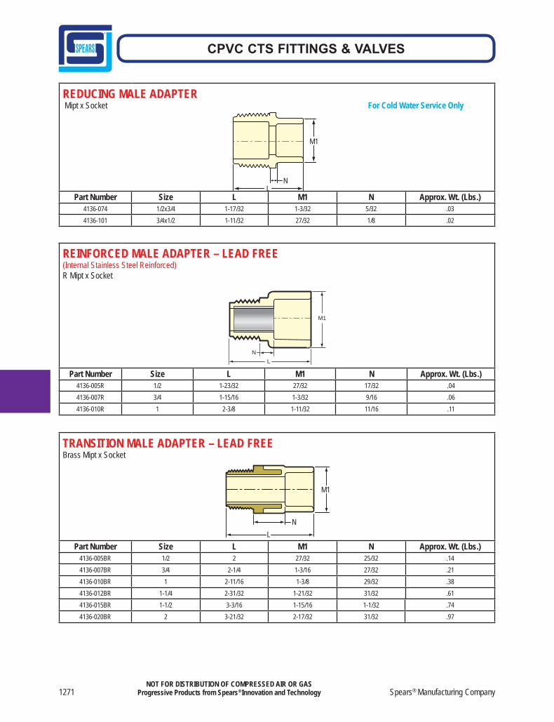
1271 Spears® Manufacturing Company
CPVC CTS FITTINGS & VALVES
NOT FOR DISTRIBUTION OF COMPRESSED AIR OR GASProgressive Products from Spears® Innovation and Technology
REDUCING MALE ADAPTER Mipt x Socket For Cold Water Service Only
M1
LN
Part Number Size L M1 N Approx. Wt. (Lbs.)4136-074 1/2x3/4 1-17/32 1-3/32 5/32 .034136-101 3/4x1/2 1-11/32 27/32 1/8 .02
TRANSITION MALE ADAPTER – LEAD FREEBrass Mipt x Socket
NL
M1
Part Number Size L M1 N Approx. Wt. (Lbs.)4136-005BR 1/2 2 27/32 25/32 .144136-007BR 3/4 2-1/4 1-3/16 27/32 .214136-010BR 1 2-11/16 1-3/8 29/32 .384136-012BR 1-1/4 2-31/32 1-21/32 31/32 .614136-015BR 1-1/2 3-3/16 1-15/16 1-1/32 .744136-020BR 2 3-21/32 2-17/32 31/32 .97
REINFORCED MALE ADAPTER – LEAD FREE(Internal Stainless Steel Reinforced)R Mipt x Socket
N
M1
L
Part Number Size L M1 N Approx. Wt. (Lbs.)4136-005R 1/2 1-23/32 27/32 17/32 .044136-007R 3/4 1-15/16 1-3/32 9/16 .064136-010R 1 2-3/8 1-11/32 11/16 .11

Made in the U.S.A. 1272
CPVC CTS FITTINGS & VALVES
NOT FOR DISTRIBUTION OF COMPRESSED AIR OR GASProgressive Products from Spears® Innovation and Technology
MALE ADAPTER Mipt x Spigot For Cold Water Service Only
PIPE O.D.
N L
Part Number Size L N Pipe O.D. Approx. Wt. (Lbs.)4161-005 1/2 1-5/16 3/16 5/8 .02
REDUCER BUSHING Spigot x Socket
PIPE O.D.
L N
Part Number Size L N Pipe O.D. Approx. Wt. (Lbs.)4137-101 3/4x1/2 27/32 1/8 7/8 .02
4137-130 1x1/2 1-1/8 5/8 1-1/8 .05
4137-131 1x3/4 1-1/16 7/16 1-1/8 .02
4137-166 1-1/4x1/2 1-13/32 7/8 1-3/8 .06
4137-167 1-1/4x3/4 1-3/8 21/32 1-3/8 .06
4137-168 1-1/4x1 1-5/16 3/8 1-3/8 .04
4137-209 1-1/2x1/2 1-21/32 1-1/8 1-5/8 .10
4137-210 1-1/2x3/4 1-5/8 29/32 1-5/8 .10
4137-211 1-1/2x1 1-19/32 21/32 1-5/8 .09
4137-212 1-1/2x1-1/4 1-19/32 7/16 1-5/8 .06
4137-247 2x1/2 2 1-15/32 2-1/8 .20
4137-248 2x3/4 2 1-9/32 2-1/8 .21
4137-249 2x1 2 1-3/32 2-1/8 .21
4137-250 2x1-1/4 1-31/32 7/8 2-1/8 .21
4137-251 2x1-1/2 2-1/32 23/32 2-1/8 .19
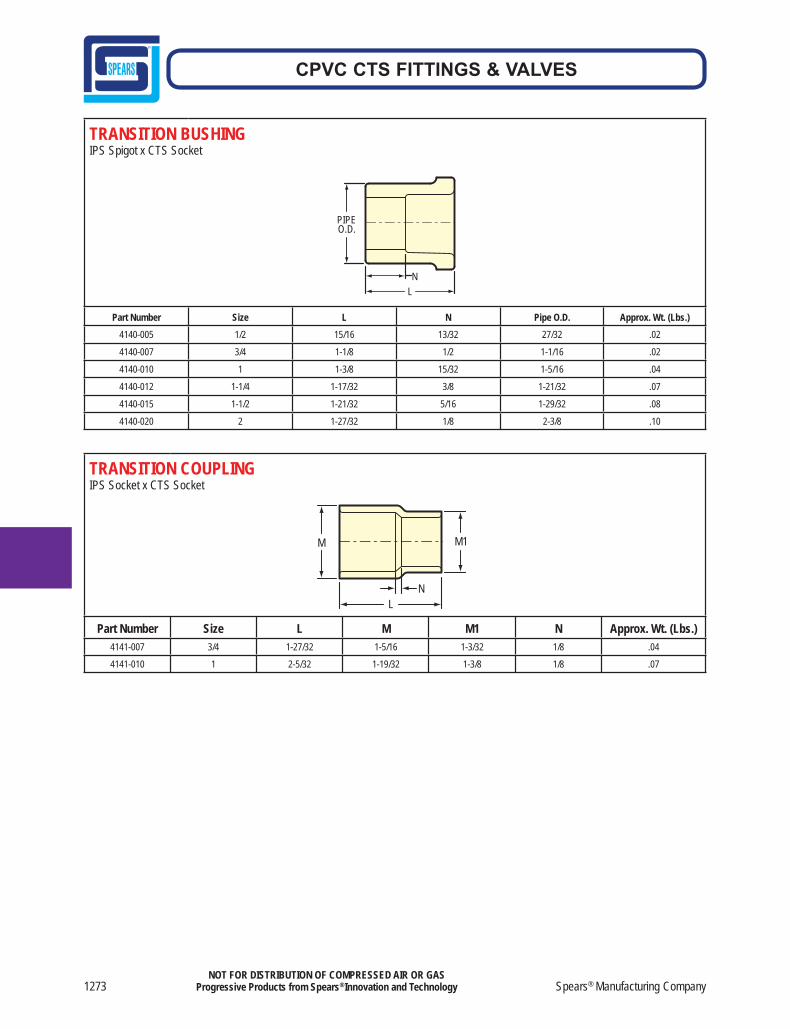
1273 Spears® Manufacturing Company
CPVC CTS FITTINGS & VALVES
NOT FOR DISTRIBUTION OF COMPRESSED AIR OR GASProgressive Products from Spears® Innovation and Technology
TRANSITION BUSHINGIPS Spigot x CTS Socket
PIPE O.D.
L N
Part Number Size L N Pipe O.D. Approx. Wt. (Lbs.)4140-005 1/2 15/16 13/32 27/32 .02
4140-007 3/4 1-1/8 1/2 1-1/16 .02
4140-010 1 1-3/8 15/32 1-5/16 .04
4140-012 1-1/4 1-17/32 3/8 1-21/32 .07
4140-015 1-1/2 1-21/32 5/16 1-29/32 .08
4140-020 2 1-27/32 1/8 2-3/8 .10
TRANSITION COUPLINGIPS Socket x CTS Socket
L
M1
N
M
Part Number Size L M M1 N Approx. Wt. (Lbs.)4141-007 3/4 1-27/32 1-5/16 1-3/32 1/8 .04
4141-010 1 2-5/32 1-19/32 1-3/8 1/8 .07
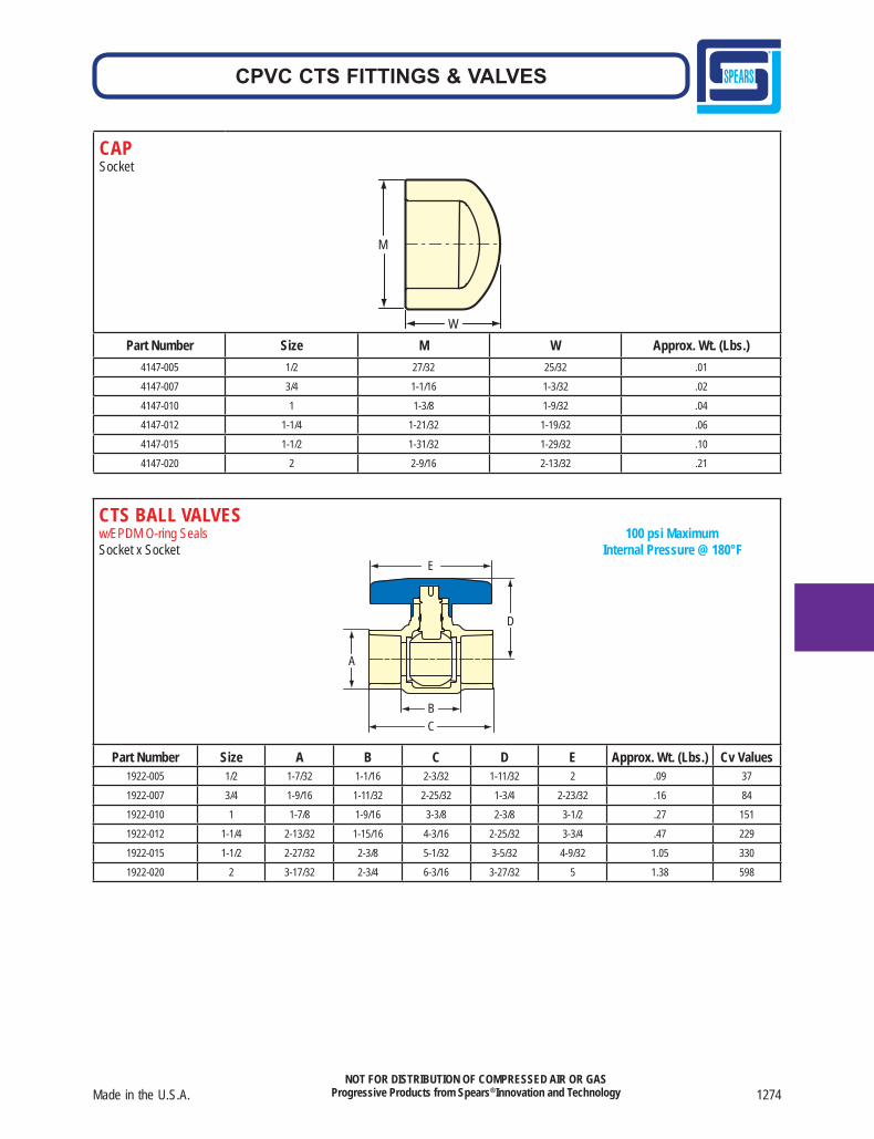
Made in the U.S.A. 1274
CPVC CTS FITTINGS & VALVES
NOT FOR DISTRIBUTION OF COMPRESSED AIR OR GASProgressive Products from Spears® Innovation and Technology
CAPSocket
W
M
Part Number Size M W Approx. Wt. (Lbs.)4147-005 1/2 27/32 25/32 .01
4147-007 3/4 1-1/16 1-3/32 .02
4147-010 1 1-3/8 1-9/32 .04
4147-012 1-1/4 1-21/32 1-19/32 .06
4147-015 1-1/2 1-31/32 1-29/32 .10
4147-020 2 2-9/16 2-13/32 .21
CTS BALL VALVESw/EPDM O-ring Seals 100 psi MaximumSocket x Socket Internal Pressure @ 180°F
A
E
D
B C
Part Number Size A B C D E Approx. Wt. (Lbs.) Cv Values1922-005 1/2 1-7/32 1-1/16 2-3/32 1-11/32 2 .09 37
1922-007 3/4 1-9/16 1-11/32 2-25/32 1-3/4 2-23/32 .16 84
1922-010 1 1-7/8 1-9/16 3-3/8 2-3/8 3-1/2 .27 151
1922-012 1-1/4 2-13/32 1-15/16 4-3/16 2-25/32 3-3/4 .47 229
1922-015 1-1/2 2-27/32 2-3/8 5-1/32 3-5/32 4-9/32 1.05 330
1922-020 2 3-17/32 2-3/4 6-3/16 3-27/32 5 1.38 598
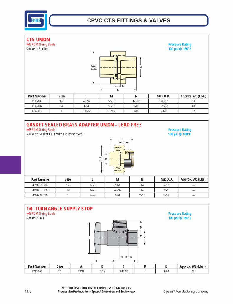
1275 Spears® Manufacturing Company
CPVC CTS FITTINGS & VALVES
NOT FOR DISTRIBUTION OF COMPRESSED AIR OR GASProgressive Products from Spears® Innovation and Technology
CTS UNION w/EPDM O-ring Seals Pressure RatingSocket x Socket 100 psi @ 180°F
Part Number Size L M N NUT O.D. Approx. Wt. (Lbs.)4197-005 1/2 2-3/16 1-1/32 1-5/32 1-25/32 .134197-007 3/4 1-3/4 1-3/32 5/16 1-23/32 .084197-010 1 2-13/32 1-17/32 9/16 2-1/2 .27
NUT O.D.
M
LN
1/4 - TURN ANGLE SUPPLY STOP w/EPDM O-ring Seals Pressure RatingSocket x NPT 100 psi @ 180°F
Part Number Size A B C D E Approx. Wt. (Lbs.)7722-005 1/2 27/32 7/16 2-13/32 1 1-3/4 .06
BC
E A
D
GASKET SEALED BRASS ADAPTER UNION – LEAD FREEw/EPDM O-ring Seals Pressure RatingSocket x Gasket FIPT With Elastomer Seal 100 psi @ 180°F
LN
MNUTO.D.
Part Number Size L M N Nut O.D. Approx. Wt. (Lbs.)4199-005BRG 1/2 1-5/8 2-1/8 3/4 2-1/8 ---
4199-007BRG 3/4 1-7/8 2-5/16 3/4 2-5/16 ---
4199-010BRG 1 2-3/8 2-5/8 15/16 2-5/8 ---
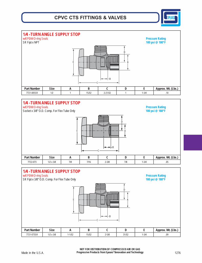
Made in the U.S.A. 1276
CPVC CTS FITTINGS & VALVES
NOT FOR DISTRIBUTION OF COMPRESSED AIR OR GASProgressive Products from Spears® Innovation and Technology
1/4 - TURN ANGLE SUPPLY STOP w/EPDM O-ring Seals Pressure RatingSR Fipt x 3/8" O.D. Comp. For Flex Tube Only 100 psi @ 180°F
B
E
C
A
D
Part Number Size A B C D E Approx. Wt. (Lbs.)7721-073SR 1/2 x 3/8 1-1/32 15/32 2-5/8 31/32 1-3/4 .09
1/4 - TURN ANGLE SUPPLY STOP w/EPDM O-ring Seals Pressure RatingSocket x 3/8" O.D. Comp. For Flex Tube Only 100 psi @ 180°F
BC
E A
D
Part Number Size A B C D E Approx. Wt. (Lbs.)7722-073 1/2 x 3/8 7/8 7/16 2-3/8 7/8 1-3/4 .05
1/4 - TURN ANGLE SUPPLY STOP w/EPDM O-ring Seals Pressure RatingSR Fipt x NPT 100 psi @ 180°F
B
E
C
A
D
Part Number Size A B C D E Approx. Wt. (Lbs.)7721-005SR 1/2 1 15/32 2-21/32 1 1-3/4 .10