cover page deficiencies summary - custom eng · cover page deficiencies summary ... ucs-66...
TRANSCRIPT

Southern Technologies
Index
Cover Page
Deficiencies SummaryNozzle ScheduleNozzle SummaryPressure SummaryRevision HistorySettings SummaryThickness SummaryWeight SummaryHydrostatic TestVacuum Summary
Cylinder #1
Ellipsoidal Head #2Straight Flange on Ellipsoidal Head #2Straight Flange on Ellipsoidal Head #1Ellipsoidal Head #1
Nozzle #1 (N1)Nozzle #2 (N2)Nozzle #3 (N3)Nozzle #4 (N4)Nozzle #5 (N5)Nozzle #6 (N6)Nozzle #7 (N7)Nozzle #8 (N8)Nozzle #9 (N9)
Legs #1
Seismic Code
Liquid Level bounded by Ellipsoidal Head #1
file:///C|/Codeware/COMPRESS/Temp/CWIndex46099080.html [9/6/2005 2:13:21 PM]

Cover Page
Cover Page
Custom Engineering2800 McClelland Ave
Erie, PA 16510
COMPRESS Pressure Vessel Design Calculations
Item: Potable Water Storage Tank
Vessel No: G-6764
Customer: Customer #2
Contract: WO# 7328
file:///C|/Codeware/COMPRESS/Temp/Southern TechnologiesCoverPage.html (1 of 2) [9/6/2005 2:13:22 PM]
Cover Page
Designer: George Clark
Date: 3/31/04
You can edit this page by selecting Cover Page settings... in the report menu.
file:///C|/Codeware/COMPRESS/Temp/Southern TechnologiesCoverPage.html (2 of 2) [9/6/2005 2:13:22 PM]

Deficiencies Summary
Deficiencies Summary
Deficiencies for Nozzle #4 (N4)Nozzle MAWP (121.2158 psi) is less than the design pressure (125.0000 psi).
Warnings Summary
Warnings for Legs #1The Skirt/Legs/Saddles Stress Increase factor is 1.30 (Set Mode Options dialog on the Calculation tab). AISC ASD supplement No. 1 (Dec. 17, 2001) paragraph A5 removed the stress increase factor of 1/3. For the specified building code the recommended stress increase factor is 1.00. (warning)
ASME B16.5 / B16.47 Flange Warnings Summary
ASME B16.5 / 16.47 Flanges with Warnings
Flange Applicable Warnings
Nozzle #3 (N3) 1
Nozzle #1 (N1) 1
Nozzle #4 (N4) 1
ASME B16.5 / 16.47 Flange Warnings
No. Warning
1 For Class 150 flanges, ASME B16.5 para. 5.4.2 recommends gaskets to be in accordance with Fig. E1, Group No. I.
file:///C|/Codeware/COMPRESS/Temp/DeficSum3CA757E9.html [9/6/2005 2:13:22 PM]

Nozzle Schedule
Nozzle Schedule
Nozzlemark Service Size
Materials
Nozzle Impact Norm Fine Grain Pad Impact Norm
Fine Grain Flange
N1 Nozzle #1
2.500" Sch 40 (Std)
SA-106 B Smls pipe
No No No N/A N/A N/A N/AWN A105 150#
N2 Nozzle #2
18" Sch 60
SA-106 C Smls pipe
No No No N/A N/A N/A N/A N/A
N3 Nozzle #3
4" Sch 80 (XS)
SA-106 B Smls pipe
No No No N/A N/A N/A N/AWN A105 150#
N4 Nozzle #4
4" Sch 80 (XS)
SA-106 B Smls pipe
No No No N/A N/A N/A N/AWN A105 150#
N5 Nozzle #5
1" 3000# - threaded
SA-105 No No No N/A N/A N/A N/A N/A
N6 Nozzle #6
1" 3000# - threaded
SA-105 No No No N/A N/A N/A N/A N/A
N7 Nozzle #7
1.500" 3000# - threaded
SA-105 No No No N/A N/A N/A N/A N/A
N8 Nozzle #8
1.500" 3000# - threaded
SA-105 No No No N/A N/A N/A N/A N/A
N9 Nozzle #9
1" 3000# - threaded
SA-105 No No No N/A N/A N/A N/A N/A
file:///C|/Codeware/COMPRESS/Temp/NozSch2B81A943.html [9/6/2005 2:13:22 PM]

Nozzle Summary
Nozzle Summary
Nozzlemark
OD(in)
tn
(in) Req tn
(in) A1? A2?
Shell ReinforcementPad Corr
(in) Aa/Ar(%)Nom t
(in) Design t(in)
User t(in)
Width(in)
tpad(in)
N1 2.88 0.2030 0.2030 Yes Yes 0.5000* 0.3862 N/A N/A 0.0000 100.0
N2 18.00 0.7500 0.0714 Yes Yes 0.5000 0.4391 N/A N/A 0.0000 100.0
N3 4.50 0.3370 0.2370 Yes Yes 0.5000* 0.3982 N/A N/A 0.0000 100.0
N4 4.50 0.3370 0.2370 Yes Yes 0.5000* 0.3982 N/A N/A 0.0000 100.0
N5 1.75 0.2175 0.1042 Yes Yes 0.5000 N/A N/A N/A 0.0000 Exempt
N6 1.75 0.2175 0.1042 Yes Yes 0.5000 N/A N/A N/A 0.0000 Exempt
N7 2.50 0.3000 0.1041 Yes Yes 0.5000* N/A N/A N/A 0.0000 Exempt
N8 2.50 0.3000 0.1041 Yes Yes 0.5000* N/A N/A N/A 0.0000 Exempt
N9 1.75 0.2175 0.1042 Yes Yes 0.5000 N/A N/A N/A 0.0000 Exempt
tn: Nozzle thickness
Req tn: Nozzle thickness required per UG-45/UG-16
Nom t: Vessel wall thickness
Design t: Required vessel wall thickness due to pressure + corrosion allowance per UG-37
User t: Local vessel wall thickness (near opening)
Aa: Area available per UG-37, governing condition
Ar: Area required per UG-37, governing condition
Corr: Corrosion allowance on nozzle wall
* Head minimum thickness after forming
file:///C|/Codeware/COMPRESS/Temp/NozSum05BB0084.html [9/6/2005 2:13:22 PM]

Pressure Summary
Pressure Summary
Pressure Summary for Chamber bounded by Ellipsoidal Head #1 and Ellipsoidal Head #2
Identifier P
Design( psi)
TDesign
(°F)
MAWP( psi)
MAP( psi)
MAEP( psi)
Teexternal
(°F)
MDMT Rating Total CorrosionAllowance
(in)
ImpactTestMDMT
(°F) Exemption
Ellipsoidal Head #2
125.0 300.0 147.00 147.21 61.66 300.0 -40.9 Note 1 0.000 No
Straight Flange on Ellipsoidal Head #2
125.0 300.0 146.15 146.44 43.45 300.0 -40.6 Note 2 0.000 No
Cylinder #1 125.0 300.0 142.83 146.44 43.45 300.0 -38.8 Note 3 0.000 No
Straight Flange on Ellipsoidal Head #1
125.0 300.0 142.76 146.44 43.45 300.0 -38.7 Note 5 0.000 No
Ellipsoidal Head #1
125.0 300.0 142.67 147.21 61.66 300.0 -38.6 Note 4 0.000 No
Legs #1 125.0 300.0 125.00 N/A N/A N/A N/A N/A N/A N/A
Nozzle #1 (N1)
125.0 300.0 169.45 174.20 36.74 300.0 -55.0 Note 6 0.000 No
Nozzle #2 (N2)
125.0 300.0 133.89 137.05 31.34 300.0 -47.6 Note 7 0.000 No
Nozzle #3 (N3)
125.0 300.0 125.38 125.38 39.06 300.0 -55.0 Note 6 0.000 No
Nozzle #4 (N4)
125.0 300.0 121.22 125.38 39.07 300.0 -55.0 Note 6 0.000 No
Nozzle #5 (N5)
125.0 300.0 208.70 209.16 43.45 300.0 -155.0 Note 8 0.000 No
Nozzle #6 (N6)
125.0 300.0 205.69 209.16 43.45 300.0 -155.0 Note 9 0.000 No
Nozzle #7 (N7)
125.0 300.0 232.51 232.51 43.45 300.0 -155.0 Note 10 0.000 No
file:///C|/Codeware/COMPRESS/Temp/PresSum07D6422D.html (1 of 3) [9/6/2005 2:13:23 PM]

Pressure Summary
Nozzle #8 (N8)
125.0 300.0 232.51 232.51 43.45 300.0 -155.0 Note 10 0.000 No
Nozzle #9 (N9)
125.0 300.0 208.48 209.16 43.45 300.0 -155.0 Note 11 0.000 No
Chamber design MDMT is -20.00°FChamber rated MDMT is -38.60°F @ 121.22 psi
Chamber MAWP hot & corroded is 121.22 psi @ 300.0°F
Chamber MAP cold & new is 125.38 psi @ 70.0°F
Chamber MAEP is 31.34 psi @ 300.0°FVacuum rings did not govern the external pressure rating.
Notes for MDMT Rating:
Note # Exemption Details
1.
Material impact test exemption temperature from Fig UCS-66 Curve B = -7 °FFig UCS-66.1 MDMT reduction = 33.9 °F, (coincident ratio = 0.6609836)
UCS-66 governing thickness = 0.5 in
2.
Material impact test exemption temperature from Fig UCS-66 Curve B = -7 °FFig UCS-66.1 MDMT reduction = 33.6 °F, (coincident ratio = 0.6642336)
UCS-66 governing thickness = 0.5 in
3.
Material impact test exemption temperature from Fig UCS-66 Curve B = -7 °FFig UCS-66.1 MDMT reduction = 31.8 °F, (coincident ratio = 0.6823238)
UCS-66 governing thickness = 0.5 in
4.
Material impact test exemption temperature from Fig UCS-66 Curve B = -7 °FFig UCS-66.1 MDMT reduction = 31.6 °F, (coincident ratio = 0.684324)
UCS-66 governing thickness = 0.5 in
5.
Material impact test exemption temperature from Fig UCS-66 Curve B = -7 °FFig UCS-66.1 MDMT reduction = 31.7 °F, (coincident ratio = 0.682717)
UCS-66 governing thickness = 0.5 in
6. Flange rating governs: UCS-66(b)(1)(b)
file:///C|/Codeware/COMPRESS/Temp/PresSum07D6422D.html (2 of 3) [9/6/2005 2:13:23 PM]

Pressure Summary
7.Nozzle impact test exemption temperature from Fig UCS-66 Curve B = -7 °FFig UCS-66.1 MDMT reduction = 40.6 °F, (coincident ratio = 0.5953)
UCS-66 governing thickness = 0.5 in.
8.Nozzle is impact test exempt to -155 °F per UCS-66(b)(3) (coincident ratio = 0.01846).
9.Nozzle is impact test exempt to -155 °F per UCS-66(b)(3) (coincident ratio = 0.01892).
10.Nozzle is impact test exempt to -155 °F per UCS-66(b)(3) (coincident ratio = 0.01926).
11.Nozzle is impact test exempt to -155 °F per UCS-66(b)(3) (coincident ratio = 0.01849).
Design notes are available on the Settings Summary page.
file:///C|/Codeware/COMPRESS/Temp/PresSum07D6422D.html (3 of 3) [9/6/2005 2:13:23 PM]

file:///C|/Codeware/COMPRESS/Temp/RevHist39480EAE.html
Revision History
No. Date Operator Notes
0 3/ 5/2004 george New vessel created ASME Division 1 [Build 6225]
1 3/11/2004 george
Converted from ASME Section VIII Division 1, 2001 Edition, A03 Addenda to ASME Section VIII Division 1, 2001 Edition, A03 Addenda. During the conversion, changes may have been made to your vessel (some may be listed above). Please check your vessel carefully.
file:///C|/Codeware/COMPRESS/Temp/RevHist39480EAE.html [9/6/2005 2:13:23 PM]

Settings Summary
Settings Summary
COMPRESS Build 6242
Units: English
Datum Line Location: 0.00" from bottom seam
Design
ASME Section VIII Division 1, 2001 Edition, A03 Addenda
Design or Rating: Get Thickness from Pressure
Minimum thickness: 1/16" per UG-16(b)
Design for cold shut down only: No
Design for lethal service (full radiography required): No
Design nozzles for: Design P, find nozzle MAWP and MAP
Corrosion weight loss: 100% of theoretical loss
UG-23 Stress Increase: 1.20
Skirt/legs stress increase: 1.3
Minimum nozzle projection: 3.0000"
Juncture calculations for α > 30 only: Yes
Preheat P-No 1 Materials > 1.25" and <= 1.50" thick: No
Butt welds are tapered per Figure UCS-66.3(a).
Hydro/Pneumatic Test
Shop Hydrotest Pressure: 1.3 times vessel MAWP
Test liquid specific gravity: 1.00
Maximum stress during test: 90% of yield
Code Interpretations
Apply interpretation VIII-1-83-66: Yes
Apply interpretation VIII-1-86-175: Yes
Apply interpretation VIII-1-83-115: Yes
file:///C|/Codeware/COMPRESS/Temp/SettingsSum6A084F93.html (1 of 2) [9/6/2005 2:13:23 PM]
Settings Summary
Apply interpretation VIII-1-01-37: Yes
Disallow UG-20(f) exemptions: No
UG-22 Loadings
UG-22 (a) Internal or External Design Pressure : Yes
UG-22 (b) Weight of the vessel and normal contents under operating or test conditions: Yes
UG-22 (c) Superimposed static reactions from weight of attached equipment (external loads): No
UG-22 (d)(2) Vessel supports such as lugs, rings, skirts, saddles and legs: Yes
UG-22 (f) Wind reactions: No
UG-22 (f) Seismic reactions: Yes
Note: UG-22 (b),(c) and (f) loads only considered when supports are present.
file:///C|/Codeware/COMPRESS/Temp/SettingsSum6A084F93.html (2 of 2) [9/6/2005 2:13:23 PM]

Thickness Summary
Thickness Summary
ComponentIdentifier Material
Diameter(in)
Length(in)
Nominal t(in)
Design t(in)
JointE Load
Ellipsoidal Head #2 SA-516 70 96.00 OD 24.25 0.5000* 0.4259 0.7000 Internal
Straight Flange on Ellipsoidal Head #2 SA-516 70 96.00 OD 2.00 0.5000 0.4281 0.7000 Internal
Cylinder #1 SA-516 70 96.00 OD 92.00 0.5000 0.4394 0.7000 Internal
Straight Flange on Ellipsoidal Head #1 SA-516 70 96.00 OD 2.00 0.5000 0.4396 0.7000 Internal
Ellipsoidal Head #1 SA-516 70 96.00 OD 24.25 0.5000* 0.4405 0.7000 Internal
Nominal t: Vessel wall nominal thickness
Design t: Required vessel thickness due to governing loading + corrosion
Joint E: Longitudinal seam joint efficiency
* Head minimum thickness after forming
Load
internal: Circumferential stress due to internal pressure governs
external: External pressure governs
Wind: Combined longitudinal stress of pressure + weight + wind governs
Seismic: Combined longitudinal stress of pressure + weight + seismic governs
file:///C|/Codeware/COMPRESS/Temp/ThkHist5515034F.html [9/6/2005 2:13:23 PM]

Weight Summary
Weight Summary
Component
Weight ( lb) Contributed by Vessel Elements
MetalNew*
MetalCorroded*
Insulation &Supports
Lining Piping
+ Liquid Operating
Liquid Test
Liquid
Ellipsoidal Head #2 1,571.75 1,571.75 0.00 0.00 0.00 2,014.25 4,566.73
Cylinder #1 3,868.66 3,868.66 0.00 0.00 0.00 23,564.21 23,564.21
Ellipsoidal Head #1 1,572.22 1,572.22 0.00 0.00 0.00 4,566.44 4,566.44
Legs #1 355.38 355.38 0.00 0.00 0.00 0.00 0.00
TOTAL: 7,368.00 7,368.00 0.00 0.00 0.00 30,144.90 32,697.37
* Shells with attached nozzles have weight reduced by material cut out for opening.
Component
Weight ( lb) Contributed by Attachments
Body Flanges Nozzles &
Flanges PackedBeds
Ladders &Platforms
Trays &Supports
Rings &
Clips
VerticalLoads
New Corroded New Corroded
Ellipsoidal Head #2
0.00 0.00 33.49 33.49 0.00 0.00 0.00 0.00 0.00
Cylinder #1 0.00 0.00 59.81 59.81 0.00 0.00 0.00 0.00 0.00
Ellipsoidal Head #1
0.00 0.00 37.48 37.48 0.00 0.00 0.00 0.00 0.00
Legs #1 0.00 0.00 0.00 0.00 0.00 0.00 0.00 0.00 0.00
TOTAL: 0.00 0.00 130.78 130.78 0.00 0.00 0.00 0.00 0.00
Vessel operating weight, Corroded: 37,644 lbVessel operating weight, New: 37,644 lbVessel empty weight, Corroded: 7,499 lbVessel empty weight, New: 7,499 lbVessel test weight, New: 40,196 lb
Vessel center of gravity location (from datum)
Vessel Lift Weight, New: 7,499 lb
file:///C|/Codeware/COMPRESS/Temp/WtSum752B5A76.html (1 of 2) [9/6/2005 2:13:23 PM]
Weight Summary
Center of Gravity: 42.94"
Vessel Capacity
Vessel Capacity** (New): 3,917 US galVessel Capacity** (Corroded): 3,917 US gal**The vessel capacity does not include volume of nozzle, piping or other attachments.
file:///C|/Codeware/COMPRESS/Temp/WtSum752B5A76.html (2 of 2) [9/6/2005 2:13:23 PM]

Hydrostatic Test
Hydrostatic Test
Shop test pressure determination for Chamber bounded by Ellipsoidal Head #1 and Ellipsoidal Head #2 based on MAWP per UG-99(b)
Shop hydrostatic test gauge pressure is 157.581 psi at 70.00 °F (the chamber MAWP = 121.216 psi)
The shop test is performed with the vessel in the horizontal position.
IdentifierLocal testpressure
psi
Test liquidstatic head
psi
UG-99stressratio
UG-99pressure
factor
Stressduring test
psi
Allowabletest stress
psi
Stressexcessive?
Ellipsoidal Head #2 (1)
161.208 3.628 1.0000 1.30 13,783 34,200 No
Straight Flange on Ellipsoidal Head #2
161.208 3.628 1.0000 1.30 15,395 34,200 No
Cylinder #1 161.208 3.628 1.0000 1.30 15,395 34,200 No
Straight Flange on Ellipsoidal Head #1
161.208 3.628 1.0000 1.30 15,395 34,200 No
Ellipsoidal Head #1 161.208 3.628 1.0000 1.30 13,783 34,200 No
Nozzle #1 (N1) 159.538 1.958 1.0000 1.30 17,465 47,250 No
Nozzle #2 (N2) 161.339 3.759 1.0000 1.30 31,323 51,300 No
Nozzle #3 (N3) 157.943 0.362 1.0000 1.30 20,922 47,250 No
Nozzle #4 (N4) 157.943 0.362 1.0000 1.30 20,920 47,250 No
Nozzle #5 (N5) 159.517 1.937 1.0000 1.30 17,994 48,600 No
Nozzle #6 (N6) 159.517 1.937 1.0000 1.30 17,994 48,600 No
Nozzle #7 (N7) 159.528 1.947 1.0000 1.30 15,287 48,600 No
Nozzle #8 (N8) 160.394 2.814 1.0000 1.30 15,502 48,600 No
Nozzle #9 (N9) 161.371 3.790 1.0000 1.30 18,203 48,600 No
Notes:(1) Ellipsoidal Head #2 limits the UG-99 stress ratio.(2) PL stresses at nozzle openings have been estimated using the method described in PVP-Vol. 399,
pages 77-82.(3) VIII-2, AD-151.1(b) used as the basis for nozzle allowable test stress.
file:///C|/Codeware/COMPRESS/Temp/CW4693648E.html (1 of 2) [9/6/2005 2:13:24 PM]

Hydrostatic Test
(4) The zero degree angular position is assumed to be up, and the test liquid height is assumed to the top-most flange.
The field test condition has not been investigated for the Chamber bounded by Ellipsoidal Head #1 and Ellipsoidal Head #2.
The test temperature of 70.00 °F is warmer than the minimum recommended temperature of -8.60 °F so the brittle fracture provision of UG-99(h) has been met.
file:///C|/Codeware/COMPRESS/Temp/CW4693648E.html (2 of 2) [9/6/2005 2:13:24 PM]

Vacuum Summary
Vacuum Summary
Component Line of Support Elevationabove Datum(in)
Length Le(in)
Ellipsoidal Head #2 - 118.25 N/A
- 1/3 depth of Ellipsoidal Head #2 101.92 N/A
Straight Flange on Ellipsoidal Head #2 Top - 94.00 111.83
Straight Flange on Ellipsoidal Head #2 Bottom - 92.00 111.83
Cylinder #1 Top - 92.00 111.83
Cylinder #1 Bottom - 0.00 111.83
Straight Flange on Ellipsoidal Head #1 Top - 0.00 111.83
Straight Flange on Ellipsoidal Head #1 Bottom - -2.00 111.83
- 1/3 depth of Ellipsoidal Head #1 -9.92 N/A
Ellipsoidal Head #1 - -26.25 N/A
Note
For main components, the listed value of 'Le' is the largest unsupported length for the component.
file:///C|/Codeware/COMPRESS/Temp/VacSum49A6DC84.html [9/6/2005 2:13:24 PM]

file:///C|/Codeware/COMPRESS/Temp/CW7C0F6A78.html
Cylinder #1
ASME Section VIII Division 1, 2001 Edition, A03 Addenda
Component: CylinderMaterial specification: SA-516 70 (ASME II-D p. 14, ln. 31)Material impact test exemption temperature from Fig UCS-66 Curve B = -7 °FFig UCS-66.1 MDMT reduction = 31.8 °F, (coincident ratio = 0.6823238)UCS-66 governing thickness = 0.5 in
Internal design pressure: P = 125 psi @ 300°FExternal design pressure: Pe = 15 psi @ 300°F
Static liquid head:
Ps =3.6097 psi(SG=1.0000, Hs=100.0000" Operating head)
Pth=3.6278 psi(SG=1.0000, Hs=100.5000", Horizontal test head)
Corrosion allowance: Inner C = 0.0000" Outer C = 0.0000"
Design MDMT = -20.00°F No impact test performedRated MDMT = -38.80°F Material is not normalized
Material is not produced to Fine Grain PracticePWHT is not performed
Radiography: Longitudinal joint - None UW-11(c) Type 1Top circumferential joint - None UW-11(c) Type 1Bottom circumferential joint - None UW-11(c) Type 1
Estimated weight: New = 3905.6875 lb corr = 3905.6875 lbCapacity: New = 2823.0135 gal corr = 2823.0135 gal
OD = 96.0000"Length Lc = 92.0000"
t = 0.5000"
Design thickness, (at 300.00°F) Appendix 1-1
t = P*Ro/(S*E + 0.40*P) + Corrosion
= 128.6097*48.0000/(20000.0000*0.70 + 0.40*128.6097) + 0.0000
file:///C|/Codeware/COMPRESS/Temp/CW7C0F6A78.html (1 of 17) [9/6/2005 2:13:26 PM]

file:///C|/Codeware/COMPRESS/Temp/CW7C0F6A78.html
= 0.4394"
Maximum allowable working pressure, (at 300.00°F) Appendix 1-1
P = S*E*t/(Ro - 0.40*t) - Ps
= 20000.0000*0.70*0.5000 / (48.0000 - 0.40*0.5000) - 3.6097= 142.8338 psi
Maximum allowable pressure, (at 70.00°F) Appendix 1-1
P = S*E*t/(Ro - 0.40*t)
= 20000.0000*0.70*0.5000 / (48.0000 - 0.40*0.5000)= 146.4435 psi
External Pressure, (Corroded & at 300.00°F) UG-28(c)
L/Do = 111.8333/96.0000 = 1.1649
Do/t = 96.0000/0.329221 = 291.5970
From table G: A = 0.000228
From table CS-2: B = 3280.4565
Pa = 4*B/(3*(Do/t))
= 4*3280.4565/(3*(96.0000/0.329221))
= 15.0000 psi
Design thickness for external pressure Pa = 15.0000 psi
= t + Corrosion = 0.329221 + 0.0000 = 0.3292"
Maximum Allowable External Pressure, (Corroded & at 300.00°F) UG-28(c)
L/Do = 111.8333/96.0000 = 1.1649
Do/t = 96.0000/0.5000 = 192.0000
From table G: A = 0.000435
From table CS-2: B = 6256.9512
Pa = 4*B/(3*(Do/t))
= 4*6256.9512/(3*(96.0000/0.5000))
file:///C|/Codeware/COMPRESS/Temp/CW7C0F6A78.html (2 of 17) [9/6/2005 2:13:26 PM]

file:///C|/Codeware/COMPRESS/Temp/CW7C0F6A78.html
= 43.4510 psi
% Extreme fiber elongation - UCS-79(d)
= (50 * t / Rf) * (1 - Rf / Ro)
= (50 * 0.5000 / 47.7500) * (1 - 47.7500 / ∞)= 0.5236 %
External Pressure + Weight + Seismic Loading Check (Bergman, ASME paper 54-A-104)
Pv = VAccel*W / (2*π*Rm) + M / (π*Rm2)
= 1.2000*5531.92 / (2*π*47.7500) + 134724.69 / (π*47.75002)
= 40.9344 lb/in
α = Pv / (Pe*Do)
= 40.934406 / (15.0000*96.0000)
= 0.0284
n = 6
m = 1.23 / (L/Do)2
= 1.23 / (111.833328/96.0000)2
= 0.9064
Ratio Pe = (n2 - 1 + m + m*α) / (n2 - 1 + m)
= (62 - 1 + 0.906369 + 0.906369*0.028427) / (62 - 1 + 0.906369)
= 1.0007
Ratio Pe * Pe ≤ MAEP design cylinder thickness is satisfactory.
External Pressure + Weight + Seismic Loading Check at Bottom Seam(Bergman, ASME paper 54-A-104)
Pv = VAccel*W / (2*π*Rm) + M / (π*Rm2)
= 1.2000*5531.92 / (2*π*47.7500) + 4669.13 / (π*47.75002)
= 22.7779 lb/in
α = Pv / (Pe*Do)
= 22.777905 / (15.0000*96.0000)
= 0.0158
n = 6
file:///C|/Codeware/COMPRESS/Temp/CW7C0F6A78.html (3 of 17) [9/6/2005 2:13:26 PM]

file:///C|/Codeware/COMPRESS/Temp/CW7C0F6A78.html
m = 1.23 / (L/Do)2
= 1.23 / (111.833328/96.0000)2
= 0.9064
Ratio Pe = (n2 - 1 + m + m*α) / (n2 - 1 + m)
= (62 - 1 + 0.906369 + 0.906369*0.015818) / (62 - 1 + 0.906369)
= 1.0004
Ratio Pe * Pe ≤ MAEP design cylinder thickness is satisfactory.
Design thickness = 0.4394"
The governing condition is due to internal pressure.
The cylinder thickness of 0.5000" is adequate.
Thickness Required Due to Pressure + External Loads
ConditionPressure P ( psi)
Allowable Stress Before UG-23 Stress Increase
( psi)Temperature
(°F)Corrosion
C (in)Location Load
Req'd Thk
Due to Tension
(in)
Req'd Thk Due to
Compression (in)
St Sc
Operating, Hot & Corroded
125.00 20000.00 13265.59 300.00 0.0000top Seismic 0.1236 0.1219
Bottom Seismic 0.1228 0.1226
Operating, Hot & New
125.00 20000.00 13265.59 300.00 0.0000top Seismic 0.1236 0.1219
Bottom Seismic 0.1228 0.1226
Hot Shut Down, Corroded
0.00 20000.00 13265.59 300.00 0.0000top Seismic 0.0000 0.0026
Bottom Seismic 0.0011 0.0014
Hot Shut Down, New
0.00 20000.00 13265.59 300.00 0.0000top Seismic 0.0000 0.0026
Bottom Seismic 0.0011 0.0014
Empty, Corroded
0.00 20000.00 13265.59 0.00 0.0000top Seismic 0.0009 0.0017
Bottom Seismic 0.0011 0.0014
Empty, top Seismic 0.0009 0.0017
file:///C|/Codeware/COMPRESS/Temp/CW7C0F6A78.html (4 of 17) [9/6/2005 2:13:26 PM]

file:///C|/Codeware/COMPRESS/Temp/CW7C0F6A78.html
New 0.00 20000.00 13265.59 0.00 0.0000Bottom Seismic 0.0011 0.0014
Vacuum -15.00 20000.00 13265.59 300.00 0.0000top Seismic 0.0224 0.0249
Bottom Seismic 0.0235 0.0238
Hot Shut Down, Corroded, Weight & Eccentric Moments Only
0.00 20000.00 13265.59 300.00 0.0000
top Weight 0.0014 0.0017
Bottom Weight 0.0014 0.0017
Allowable Compressive Stress, Hot and Corroded- ScHC, (table CS-2)
A = 0.125 / (Ro / t)
= 0.125 / (48.0000 / 0.5000)
= 0.001302
B = 13265.5928 psi
S = 20000.0000 / 1.0000
= 20000.0000 psi
ScHC = 13265.5928 psi
Allowable Compressive Stress, Hot and New- ScHN
ScHN = ScHC
= 13265.5928 psi
Allowable Compressive Stress, Cold and New- ScCN, (table CS-2)
A = 0.125 / (Ro / t)
= 0.125 / (48.0000 / 0.5000)
= 0.001302
B = 13265.5928 psi
S = 20000.0000 / 1.0000
= 20000.0000 psi
file:///C|/Codeware/COMPRESS/Temp/CW7C0F6A78.html (5 of 17) [9/6/2005 2:13:26 PM]

file:///C|/Codeware/COMPRESS/Temp/CW7C0F6A78.html
ScCN = 13265.5928 psi
Allowable Compressive Stress, Cold and Corroded- ScCC
ScCC = ScCN
= 13265.5928 psi
Allowable Compressive Stress, Vacuum and Corroded- ScVC, (table CS-2)
A = 0.125 / (Ro / t)
= 0.125 / (48.0000 / 0.5000)
= 0.001302
B = 13265.5928 psi
S = 20000.0000 / 1.0000
= 20000.0000 psi
ScVC = 13265.5928 psi
Operating, Hot & Corroded, Seismic, Above Support Point
tp = P*R/(2*St*Ks*Ec + 0.40*|P|) (Pressure)
= 125.0000*47.5000/(2*20000.0000*1.2000*1.00 + 0.40*|125.0000|)
= 0.1236"
tm = M/(π*Rm2*St*Ks*Ec) (bending)
= 134724.69/(π*47.75002*20000.0000*1.2000*1.00)
= 0.0008"
tw = W/(2*π*Rm*St*Ks*Ec) (Weight)
= 5531.92/(2*π*47.7500*20000.0000*1.2000*1.00)
= 0.0008"
tt = tp + tm - tw (total required, tensile)
= 0.123569 + 0.000784 - (0.000768)
= 0.1236"
twc = VAccel * W/(2*π*Rm*St*Ks*Ec) (Weight)
= 1.2000 * 5531.92/(2*π*47.7500*20000.0000*1.2000*1.00)
file:///C|/Codeware/COMPRESS/Temp/CW7C0F6A78.html (6 of 17) [9/6/2005 2:13:26 PM]

file:///C|/Codeware/COMPRESS/Temp/CW7C0F6A78.html
= 0.0009"
tc = |tmc + twc - tpc| (total, net tensile)
= |0.000784 + (0.000922) - (0.123569)|
= 0.1219"
Maximum allowable working pressure, Longitudinal Stress
P = 2*St*Ks*Ec*(t-tm+tw) / (R - 0.40*(t-tm+tw))
=2*20000.0000*1.2000*1.00*(0.5000-0.000784+(0.000768)) / (47.5000 - 0.40*(0.5000-0.000784+(0.000768)))
= 507.3839 psi
Operating, Hot & New, Seismic, Above Support Point
tp = P*R/(2*St*Ks*Ec + 0.40*|P|) (Pressure)
= 125.0000*47.5000/(2*20000.0000*1.2000*1.00 + 0.40*|125.0000|)
= 0.1236"
tm = M/(π*Rm2*St*Ks*Ec) (bending)
= 134724.69/(π*47.75002*20000.0000*1.2000*1.00)
= 0.0008"
tw = W/(2*π*Rm*St*Ks*Ec) (Weight)
= 5531.92/(2*π*47.7500*20000.0000*1.2000*1.00)
= 0.0008"
tt = tp + tm - tw (total required, tensile)
= 0.123569 + 0.000784 - (0.000768)
= 0.1236"
twc = VAccel * W/(2*π*Rm*St*Ks*Ec) (Weight)
= 1.2000 * 5531.92/(2*π*47.7500*20000.0000*1.2000*1.00)
= 0.0009"
tc = |tmc + twc - tpc| (total, net tensile)
= |0.000784 + (0.000922) - (0.123569)|
= 0.1219"
Maximum allowable working pressure, Longitudinal Stress
file:///C|/Codeware/COMPRESS/Temp/CW7C0F6A78.html (7 of 17) [9/6/2005 2:13:26 PM]

file:///C|/Codeware/COMPRESS/Temp/CW7C0F6A78.html
P = 2*St*Ks*Ec*(t-tm+tw) / (R - 0.40*(t-tm+tw))
=2*20000.0000*1.2000*1.00*(0.5000-0.000784+(0.000768)) / (47.5000 - 0.40*(0.5000-0.000784+(0.000768)))
= 507.3839 psi
Hot Shut Down, Corroded, Seismic, Above Support Point
tp = 0.0000" (Pressure)
tm = M/(π*Rm2*St*Ks*Ec) (bending)
= 134724.69/(π*47.75002*20000.0000*1.2000*1.00)
= 0.0008"
tw = W/(2*π*Rm*St*Ks*Ec) (Weight)
= 5531.92/(2*π*47.7500*20000.0000*1.2000*1.00)
= 0.0008"
tt = tp + tm - tw (total required, tensile)
= 0.000000 + 0.000784 - (0.000768)
= 0.0000"
tmc = M/(π*Rm2*Sc*Ks) (bending)
= 134724.69/(π*47.75002*13265.5928*1.2000)
= 0.0012"
twc = VAccel * W/(2*π*Rm*Sc*Ks) (Weight)
= 1.2000 * 5531.92/(2*π*47.7500*13265.5928*1.2000)
= 0.0014"
tc = tmc + twc - tpc (total required, compressive)
= 0.001182 + (0.001390) - (0.000000)
= 0.0026"
Hot Shut Down, New, Seismic, Above Support Point
tp = 0.0000" (Pressure)
tm = M/(π*Rm2*St*Ks*Ec) (bending)
= 134724.69/(π*47.75002*20000.0000*1.2000*1.00)
file:///C|/Codeware/COMPRESS/Temp/CW7C0F6A78.html (8 of 17) [9/6/2005 2:13:26 PM]

file:///C|/Codeware/COMPRESS/Temp/CW7C0F6A78.html
= 0.0008"
tw = W/(2*π*Rm*St*Ks*Ec) (Weight)
= 5531.92/(2*π*47.7500*20000.0000*1.2000*1.00)
= 0.0008"
tt = tp + tm - tw (total required, tensile)
= 0.000000 + 0.000784 - (0.000768)
= 0.0000"
tmc = M/(π*Rm2*Sc*Ks) (bending)
= 134724.69/(π*47.75002*13265.5928*1.2000)
= 0.0012"
twc = VAccel * W/(2*π*Rm*Sc*Ks) (Weight)
= 1.2000 * 5531.92/(2*π*47.7500*13265.5928*1.2000)
= 0.0014"
tc = tmc + twc - tpc (total required, compressive)
= 0.001182 + (0.001390) - (0.000000)
= 0.0026"
Empty, Corroded, Seismic, Above Support Point
tp = 0.0000" (Pressure)
tm = M/(π*Rm2*Sc*Ks) (bending)
= 32162.91/(π*47.75002*13265.5928*1.2000)
= 0.0003"
tw = W/(2*π*Rm*Sc*Ks) (Weight)
= 5531.92/(2*π*47.7500*13265.5928*1.2000)
= 0.0012"
tt = |tp + tm - tw| (total, net compressive)
= |0.000000 + 0.000282 - (0.001158)|
= 0.0009"
twc = VAccel * W/(2*π*Rm*Sc*Ks) (Weight)
= 1.2000 * 5531.92/(2*π*47.7500*13265.5928*1.2000)
= 0.0014"
file:///C|/Codeware/COMPRESS/Temp/CW7C0F6A78.html (9 of 17) [9/6/2005 2:13:26 PM]

file:///C|/Codeware/COMPRESS/Temp/CW7C0F6A78.html
tc = tmc + twc - tpc (total required, compressive)
= 0.000282 + (0.001390) - (0.000000)
= 0.0017"
Empty, New, Seismic, Above Support Point
tp = 0.0000" (Pressure)
tm = M/(π*Rm2*Sc*Ks) (bending)
= 32162.91/(π*47.75002*13265.5928*1.2000)
= 0.0003"
tw = W/(2*π*Rm*Sc*Ks) (Weight)
= 5531.92/(2*π*47.7500*13265.5928*1.2000)
= 0.0012"
tt = |tp + tm - tw| (total, net compressive)
= |0.000000 + 0.000282 - (0.001158)|
= 0.0009"
twc = VAccel * W/(2*π*Rm*Sc*Ks) (Weight)
= 1.2000 * 5531.92/(2*π*47.7500*13265.5928*1.2000)
= 0.0014"
tc = tmc + twc - tpc (total required, compressive)
= 0.000282 + (0.001390) - (0.000000)
= 0.0017"
Vacuum, Seismic, Above Support Point
tp = P*R/(2*Sc*Ks + 0.40*|P|) (Pressure)
= -15.0000*47.5000/(2*13265.5928*1.2000 + 0.40*|15.0000|)
= -0.0224"
tm = M/(π*Rm2*Sc*Ks) (bending)
= 134724.69/(π*47.75002*13265.5928*1.2000)
= 0.0012"
tw = W/(2*π*Rm*Sc*Ks) (Weight)
file:///C|/Codeware/COMPRESS/Temp/CW7C0F6A78.html (10 of 17) [9/6/2005 2:13:26 PM]

file:///C|/Codeware/COMPRESS/Temp/CW7C0F6A78.html
= 5531.92/(2*π*47.7500*13265.5928*1.2000)
= 0.0012"
tt = |tp + tm - tw| (total, net compressive)
= |-0.022375 + 0.001182 - (0.001158)|
= 0.0224"
twc = VAccel * W/(2*π*Rm*Sc*Ks) (Weight)
= 1.2000 * 5531.92/(2*π*47.7500*13265.5928*1.2000)
= 0.0014"
tc = tmc + twc - tpc (total required, compressive)
= 0.001182 + (0.001390) - (-0.022375)
= 0.0249"
Hot Shut Down, Corroded, Weight & Eccentric Moments Only, Seismic, Above Support Point
tp = 0.0000" (Pressure)
tm = M/(π*Rm2*Sc*Ks) (bending)
= 1544.32/(π*47.75002*13265.5928*1.0000)
= 0.0000"
tw = W/(2*π*Rm*Sc*Ks) (Weight)
= 5531.92/(2*π*47.7500*13265.5928*1.0000)
= 0.0014"
tt = |tp + tm - tw| (total, net compressive)
= |0.000000 + 0.000016 - (0.001390)|
= 0.0014"
twc = VAccel * W/(2*π*Rm*Sc*Ks) (Weight)
= 1.2000 * 5531.92/(2*π*47.7500*13265.5928*1.0000)
= 0.0017"
tc = tmc + twc - tpc (total required, compressive)
= 0.000016 + (0.001668) - (0.000000)
= 0.0017"
Operating, Hot & Corroded, Seismic, Below Support Point
file:///C|/Codeware/COMPRESS/Temp/CW7C0F6A78.html (11 of 17) [9/6/2005 2:13:26 PM]

file:///C|/Codeware/COMPRESS/Temp/CW7C0F6A78.html
tp = P*R/(2*St*Ks*Ec + 0.40*|P|) (Pressure)
= 125.0000*47.5000/(2*20000.0000*1.2000*1.00 + 0.40*|125.0000|)
= 0.1236"
tm = M/(π*Rm2*St*Ks*Ec) (bending)
= 4669.13/(π*47.75002*20000.0000*1.2000*1.00)
= 0.0000"
tw = W/(2*π*Rm*St*Ks*Ec) (Weight)
= 5531.92/(2*π*47.7500*20000.0000*1.2000*1.00)
= 0.0008"
tt = tp + tm - tw (total required, tensile)
= 0.123569 + 0.000027 - (0.000768)
= 0.1228"
twc = VAccel * W/(2*π*Rm*St*Ks*Ec) (Weight)
= 1.2000 * 5531.92/(2*π*47.7500*20000.0000*1.2000*1.00)
= 0.0009"
tc = |tmc + twc - tpc| (total, net tensile)
= |0.000027 + (0.000922) - (0.123569)|
= 0.1226"
Maximum allowable working pressure, Longitudinal Stress
P = 2*St*Ks*Ec*(t-tm+tw) / (R - 0.40*(t-tm+tw))
=2*20000.0000*1.2000*1.00*(0.5000-0.000027+(0.000768)) / (47.5000 - 0.40*(0.5000-0.000027+(0.000768)))
= 508.1549 psi
Operating, Hot & New, Seismic, Below Support Point
tp = P*R/(2*St*Ks*Ec + 0.40*|P|) (Pressure)
= 125.0000*47.5000/(2*20000.0000*1.2000*1.00 + 0.40*|125.0000|)
= 0.1236"
tm = M/(π*Rm2*St*Ks*Ec) (bending)
file:///C|/Codeware/COMPRESS/Temp/CW7C0F6A78.html (12 of 17) [9/6/2005 2:13:26 PM]

file:///C|/Codeware/COMPRESS/Temp/CW7C0F6A78.html
= 4669.13/(π*47.75002*20000.0000*1.2000*1.00)
= 0.0000"
tw = W/(2*π*Rm*St*Ks*Ec) (Weight)
= 5531.92/(2*π*47.7500*20000.0000*1.2000*1.00)
= 0.0008"
tt = tp + tm - tw (total required, tensile)
= 0.123569 + 0.000027 - (0.000768)
= 0.1228"
twc = VAccel * W/(2*π*Rm*St*Ks*Ec) (Weight)
= 1.2000 * 5531.92/(2*π*47.7500*20000.0000*1.2000*1.00)
= 0.0009"
tc = |tmc + twc - tpc| (total, net tensile)
= |0.000027 + (0.000922) - (0.123569)|
= 0.1226"
Maximum allowable working pressure, Longitudinal Stress
P = 2*St*Ks*Ec*(t-tm+tw) / (R - 0.40*(t-tm+tw))
=2*20000.0000*1.2000*1.00*(0.5000-0.000027+(0.000768)) / (47.5000 - 0.40*(0.5000-0.000027+(0.000768)))
= 508.1549 psi
Hot Shut Down, Corroded, Seismic, Below Support Point
tp = 0.0000" (Pressure)
tm = M/(π*Rm2*Sc*Ks) (bending)
= 4669.13/(π*47.75002*13265.5928*1.2000)
= 0.0000"
tw = W/(2*π*Rm*Sc*Ks) (Weight)
= 5531.92/(2*π*47.7500*13265.5928*1.2000)
= 0.0012"
tt = |tp + tm - tw| (total, net compressive)
= |0.000000 + 0.000041 - (0.001158)|
file:///C|/Codeware/COMPRESS/Temp/CW7C0F6A78.html (13 of 17) [9/6/2005 2:13:26 PM]

file:///C|/Codeware/COMPRESS/Temp/CW7C0F6A78.html
= 0.0011"
twc = VAccel * W/(2*π*Rm*Sc*Ks) (Weight)
= 1.2000 * 5531.92/(2*π*47.7500*13265.5928*1.2000)
= 0.0014"
tc = tmc + twc - tpc (total required, compressive)
= 0.000041 + (0.001390) - (0.000000)
= 0.0014"
Hot Shut Down, New, Seismic, Below Support Point
tp = 0.0000" (Pressure)
tm = M/(π*Rm2*Sc*Ks) (bending)
= 4669.13/(π*47.75002*13265.5928*1.2000)
= 0.0000"
tw = W/(2*π*Rm*Sc*Ks) (Weight)
= 5531.92/(2*π*47.7500*13265.5928*1.2000)
= 0.0012"
tt = |tp + tm - tw| (total, net compressive)
= |0.000000 + 0.000041 - (0.001158)|
= 0.0011"
twc = VAccel * W/(2*π*Rm*Sc*Ks) (Weight)
= 1.2000 * 5531.92/(2*π*47.7500*13265.5928*1.2000)
= 0.0014"
tc = tmc + twc - tpc (total required, compressive)
= 0.000041 + (0.001390) - (0.000000)
= 0.0014"
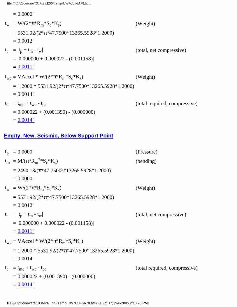
Empty, Corroded, Seismic, Below Support Point
tp = 0.0000" (Pressure)
tm = M/(π*Rm2*Sc*Ks) (bending)
= 2490.13/(π*47.75002*13265.5928*1.2000)
file:///C|/Codeware/COMPRESS/Temp/CW7C0F6A78.html (14 of 17) [9/6/2005 2:13:26 PM]
file:///C|/Codeware/COMPRESS/Temp/CW7C0F6A78.html
= 0.0000"
tw = W/(2*π*Rm*Sc*Ks) (Weight)
= 5531.92/(2*π*47.7500*13265.5928*1.2000)
= 0.0012"
tt = |tp + tm - tw| (total, net compressive)
= |0.000000 + 0.000022 - (0.001158)|
= 0.0011"
twc = VAccel * W/(2*π*Rm*Sc*Ks) (Weight)
= 1.2000 * 5531.92/(2*π*47.7500*13265.5928*1.2000)
= 0.0014"
tc = tmc + twc - tpc (total required, compressive)
= 0.000022 + (0.001390) - (0.000000)
= 0.0014"
Empty, New, Seismic, Below Support Point
tp = 0.0000" (Pressure)
tm = M/(π*Rm2*Sc*Ks) (bending)
= 2490.13/(π*47.75002*13265.5928*1.2000)
= 0.0000"
tw = W/(2*π*Rm*Sc*Ks) (Weight)
= 5531.92/(2*π*47.7500*13265.5928*1.2000)
= 0.0012"
tt = |tp + tm - tw| (total, net compressive)
= |0.000000 + 0.000022 - (0.001158)|
= 0.0011"
twc = VAccel * W/(2*π*Rm*Sc*Ks) (Weight)
= 1.2000 * 5531.92/(2*π*47.7500*13265.5928*1.2000)
= 0.0014"
tc = tmc + twc - tpc (total required, compressive)
= 0.000022 + (0.001390) - (0.000000)
= 0.0014"
file:///C|/Codeware/COMPRESS/Temp/CW7C0F6A78.html (15 of 17) [9/6/2005 2:13:26 PM]
file:///C|/Codeware/COMPRESS/Temp/CW7C0F6A78.html
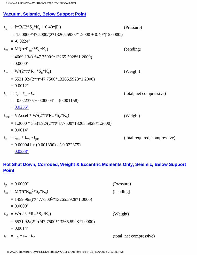
Vacuum, Seismic, Below Support Point
tp = P*R/(2*Sc*Ks + 0.40*|P|) (Pressure)
= -15.0000*47.5000/(2*13265.5928*1.2000 + 0.40*|15.0000|)
= -0.0224"
tm = M/(π*Rm2*Sc*Ks) (bending)
= 4669.13/(π*47.75002*13265.5928*1.2000)
= 0.0000"
tw = W/(2*π*Rm*Sc*Ks) (Weight)
= 5531.92/(2*π*47.7500*13265.5928*1.2000)
= 0.0012"
tt = |tp + tm - tw| (total, net compressive)
= |-0.022375 + 0.000041 - (0.001158)|
= 0.0235"
twc = VAccel * W/(2*π*Rm*Sc*Ks) (Weight)
= 1.2000 * 5531.92/(2*π*47.7500*13265.5928*1.2000)
= 0.0014"
tc = tmc + twc - tpc (total required, compressive)
= 0.000041 + (0.001390) - (-0.022375)
= 0.0238"
Hot Shut Down, Corroded, Weight & Eccentric Moments Only, Seismic, Below Support Point
tp = 0.0000" (Pressure)
tm = M/(π*Rm2*Sc*Ks) (bending)
= 1459.96/(π*47.75002*13265.5928*1.0000)
= 0.0000"
tw = W/(2*π*Rm*Sc*Ks) (Weight)
= 5531.92/(2*π*47.7500*13265.5928*1.0000)
= 0.0014"
tt = |tp + tm - tw| (total, net compressive)
file:///C|/Codeware/COMPRESS/Temp/CW7C0F6A78.html (16 of 17) [9/6/2005 2:13:26 PM]

file:///C|/Codeware/COMPRESS/Temp/CW7C0F6A78.html
= |0.000000 + 0.000015 - (0.001390)|
= 0.0014"
twc = VAccel * W/(2*π*Rm*Sc*Ks) (Weight)
= 1.2000 * 5531.92/(2*π*47.7500*13265.5928*1.0000)
= 0.0017"
tc = tmc + twc - tpc (total required, compressive)
= 0.000015 + (0.001668) - (0.000000)
= 0.0017"
file:///C|/Codeware/COMPRESS/Temp/CW7C0F6A78.html (17 of 17) [9/6/2005 2:13:26 PM]

Ellipsoidal Head #2
Ellipsoidal Head #2
ASME Section VIII, Division 1, 2001 Edition, A03 Addenda
Component: Ellipsoidal Head Material Specification: SA-516 70 (ASME II-D p.14, ln. 31)Material impact test exemption temperature from Fig UCS-66 Curve B = -7 °FFig UCS-66.1 MDMT reduction = 33.9 °F, (coincident ratio = 0.6609836)UCS-66 governing thickness = 0.5 in
Internal design pressure: P = 125 psi @ 300 °FExternal design pressure: Pe = 15 psi @ 300 °F
Static liquid head:
Ps= 0.2166 psi (SG=1, Hs=8" Operating head)
Pth= 3.6278 psi (SG=1, Hs=100.5" Horizontal test head)
Corrosion allowance: Inner C = 0" Outer C = 0"
Design MDMT = -20°F No impact test performed Rated MDMT = -40.9°F Material is not normalized
Material is not produced to fine grain practice PWHT is not performed Do not Optimize MDMT / Find MAWP
Radiography: Category A joints - None UW-11(c) Type 1 Head to shell seam - None UW-11(c) Type 1
Estimated weight*: new = 1,571.70 lb corr = 1,571.70 lb Capacity*: new = 547.2 US gal corr = 547.2 US gal* includes straight flange
Outer diameter = 96"Minimum head thickness = 0.5"Head ratio D/2h = 2 (new)Head ratio D/2h = 2 (corroded)Straight flange length Lsf = 2"Nominal straight flange thickness tsf = 0.5"
file:///C|/Codeware/COMPRESS/Temp/CW1ECD4FC9.html (1 of 4) [9/6/2005 2:13:26 PM]

Ellipsoidal Head #2
Insulation thk*: 0" density: 0 lb/ft3 weight: 0 lb Insulation support ring spacing:
0" individual weight: 0 lb total weight: 0 lb
Lining/ref thk*: 0" density: 0 lb/ft3 weight: 0 lb* includes straight flange if applicable
Results Summary
The governing condition is internal pressure.Minimum thickness per UG-16 = 0.0625" + 0" = 0.0625"Design thickness due to internal pressure (t) = 0.4259"Design thickness due to external pressure (te) = 0.247"
Maximum allowable working pressure (MAWP) = 146.9969 psi
Maximum allowable pressure (MAP) = 147.2135 psi
Maximum allowable external pressure (MAEP) = 61.6617 psi
K (Corroded)
K = (1/6)*[2 + (D / (2*h))2]= (1/6)*[2 + (95 / (2*23.75))2]= 1
K (New)
K = (1/6)*[2 + (D / (2*h))2]= (1/6)*[2 + (95 / (2*23.75))2]= 1
Design thickness for internal pressure, (Corroded at 300 °F) Appendix 1-4(c)
t = P*Do*K / (2*S*E + 2*P*(K - 0.1)) + Corrosion
= 125.2166*96*1 / (2*20000*0.7 + 2*125.2166*(1 - 0.1)) + 0= 0.4259"
The head internal pressure design thickness is 0.4259".
Maximum allowable working pressure, (Corroded at 300 °F) Appendix 1-4(c)
P = 2*S*E*t / (K*Do - 2*t*(K - 0.1)) - Ps
file:///C|/Codeware/COMPRESS/Temp/CW1ECD4FC9.html (2 of 4) [9/6/2005 2:13:26 PM]
Ellipsoidal Head #2
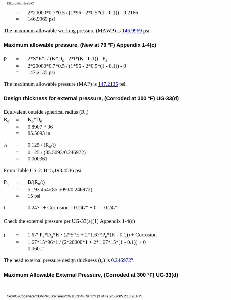
= 2*20000*0.7*0.5 / (1*96 - 2*0.5*(1 - 0.1)) - 0.2166= 146.9969 psi
The maximum allowable working pressure (MAWP) is 146.9969 psi.
Maximum allowable pressure, (New at 70 °F) Appendix 1-4(c)
P = 2*S*E*t / (K*Do - 2*t*(K - 0.1)) - Ps
= 2*20000*0.7*0.5 / (1*96 - 2*0.5*(1 - 0.1)) - 0= 147.2135 psi
The maximum allowable pressure (MAP) is 147.2135 psi.
Design thickness for external pressure, (Corroded at 300 °F) UG-33(d)
Equivalent outside spherical radius (Ro)
Ro = Ko*Do
= 0.8907 * 96 = 85.5093 in
A = 0.125 / (Ro/t)
= 0.125 / (85.5093/0.246972) = 0.000361
From Table CS-2: B=5,193.4536 psi
Pa = B/(Ro/t)
= 5,193.454/(85.5093/0.246972) = 15 psi
t = 0.247" + Corrosion = 0.247" + 0" = 0.247"
Check the external pressure per UG-33(a)(1) Appendix 1-4(c)
t = 1.67*Pe*Do*K / (2*S*E + 2*1.67*Pe*(K - 0.1)) + Corrosion
= 1.67*15*96*1 / (2*20000*1 + 2*1.67*15*(1 - 0.1)) + 0= 0.0601"
The head external pressure design thickness (te) is 0.246972".
Maximum Allowable External Pressure, (Corroded at 300 °F) UG-33(d)
file:///C|/Codeware/COMPRESS/Temp/CW1ECD4FC9.html (3 of 4) [9/6/2005 2:13:26 PM]

Ellipsoidal Head #2
Equivalent outside spherical radius (Ro)
Ro = Ko*Do
= 0.8907 * 96 = 85.5093 in
A = 0.125 / (Ro/t)
= 0.125 / (85.5093/0.5) = 0.000731
From Table CS-2: B=10,545.2891 psi
Pa = B/(Ro/t)
= 10,545.29/(85.5093/0.5) = 61.6617 psi
Check the Maximum External Pressure, UG-33(a)(1) Appendix 1-4(c)
P = 2*S*E*t / ((K*Do - 2*t*(K - 0.1))*1.67) - Ps2
= 2*20000*1*0.5 / ((1*96 - 2*0.5*(1 - 0.1))*1.67) - 0= 125.9311 psi
The maximum allowable external pressure (MAEP) is 61.6617 psi.
% Extreme fiber elongation - UCS-79(d)
= (75*t / Rf)*(1 - Rf / Ro)
= (75*0.5 / 16.4)*(1 - 16.4 / ∞)
= 2.2866%
The extreme fiber elongation does not exceed 5%.
file:///C|/Codeware/COMPRESS/Temp/CW1ECD4FC9.html (4 of 4) [9/6/2005 2:13:26 PM]

Straight Flange on Ellipsoidal Head #2
Straight Flange on Ellipsoidal Head #2
ASME Section VIII Division 1, 2001 Edition, A03 Addenda
Component: Straight FlangeMaterial specification: SA-516 70 (ASME II-D p. 14, ln. 31)Material impact test exemption temperature from Fig UCS-66 Curve B = -7 °FFig UCS-66.1 MDMT reduction = 33.6 °F, (coincident ratio = 0.6642336)UCS-66 governing thickness = 0.5 in
Internal design pressure: P = 125 psi @ 300°FExternal design pressure: Pe = 15 psi @ 300°F
Static liquid head:
Ps =0.2888 psi(SG=1.0000, Hs=8.0000" Operating head)
Pth=3.6278 psi(SG=1.0000, Hs=100.5000", Horizontal test head)
Corrosion allowance: Inner C = 0.0000" Outer C = 0.0000"
Design MDMT = -20.00°F No impact test performedRated MDMT = -40.60°F Material is not normalized
Material is not produced to Fine Grain PracticePWHT is not performed
Radiography: Longitudinal joint - None UW-11(c) Type 1Circumferential joint - None UW-11(c) Type 1
Estimated weight: New = 84.9063 lb corr = 84.9063 lbCapacity: New = 61.3699 gal corr = 61.3699 gal
OD = 96.0000"Length Lc = 2.0000"
t = 0.5000"
Design thickness, (at 300.00°F) Appendix 1-1
t = P*Ro/(S*E + 0.40*P) + Corrosion
= 125.2888*48.0000/(20000.0000*0.70 + 0.40*125.2888) + 0.0000= 0.4281"
file:///C|/Codeware/COMPRESS/Temp/CW0AF00553.html (1 of 10) [9/6/2005 2:13:27 PM]

Straight Flange on Ellipsoidal Head #2
Maximum allowable working pressure, (at 300.00°F) Appendix 1-1
P = S*E*t/(Ro - 0.40*t) - Ps
= 20000.0000*0.70*0.5000 / (48.0000 - 0.40*0.5000) - 0.2888= 146.1547 psi
Maximum allowable pressure, (at 70.00°F) Appendix 1-1
P = S*E*t/(Ro - 0.40*t)
= 20000.0000*0.70*0.5000 / (48.0000 - 0.40*0.5000)= 146.4435 psi
External Pressure, (Corroded & at 300.00°F) UG-28(c)
L/Do = 111.8333/96.0000 = 1.1649
Do/t = 96.0000/0.329221 = 291.5970
From table G: A = 0.000228
From table CS-2: B = 3280.4565
Pa = 4*B/(3*(Do/t))
= 4*3280.4565/(3*(96.0000/0.329221))
= 15.0000 psi
Design thickness for external pressure Pa = 15.0000 psi
= t + Corrosion = 0.329221 + 0.0000 = 0.3292"
Maximum Allowable External Pressure, (Corroded & at 300.00°F) UG-28(c)
L/Do = 111.8333/96.0000 = 1.1649
Do/t = 96.0000/0.5000 = 192.0000
From table G: A = 0.000435
From table CS-2: B = 6256.9512
Pa = 4*B/(3*(Do/t))
= 4*6256.9512/(3*(96.0000/0.5000))
file:///C|/Codeware/COMPRESS/Temp/CW0AF00553.html (2 of 10) [9/6/2005 2:13:27 PM]
Straight Flange on Ellipsoidal Head #2
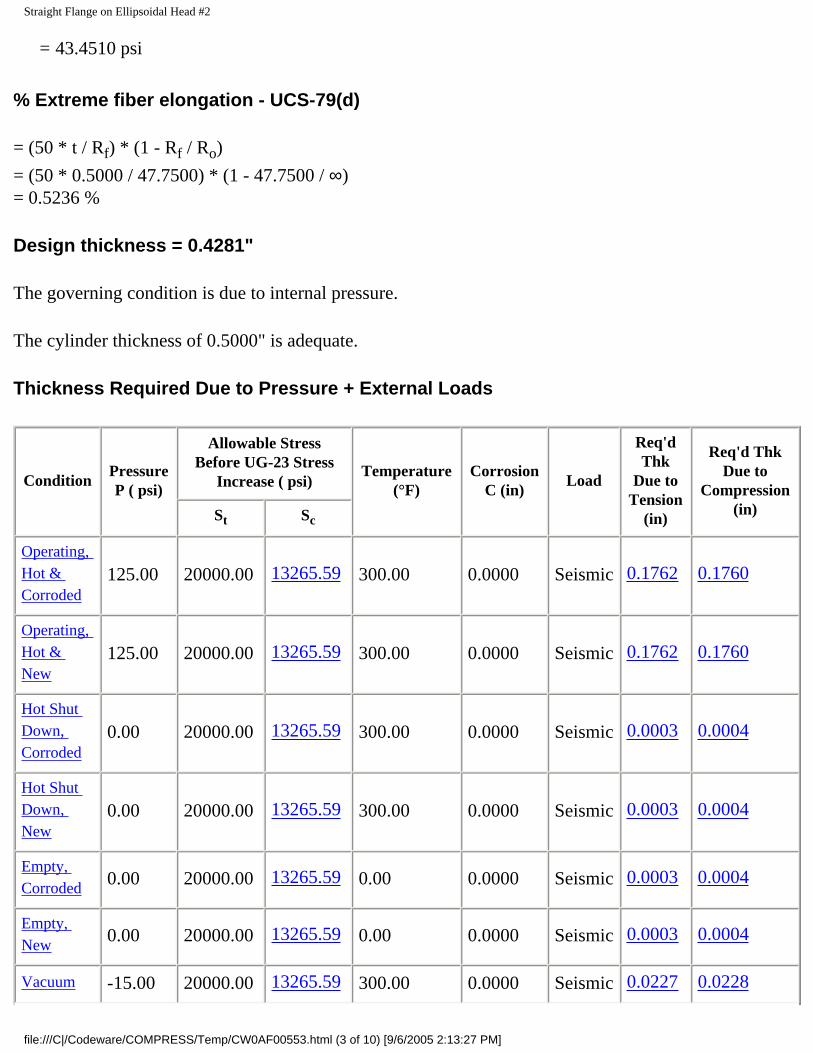
= 43.4510 psi
% Extreme fiber elongation - UCS-79(d)
= (50 * t / Rf) * (1 - Rf / Ro)
= (50 * 0.5000 / 47.7500) * (1 - 47.7500 / ∞)= 0.5236 %
Design thickness = 0.4281"
The governing condition is due to internal pressure.
The cylinder thickness of 0.5000" is adequate.
Thickness Required Due to Pressure + External Loads
ConditionPressure P ( psi)
Allowable Stress Before UG-23 Stress
Increase ( psi)Temperature
(°F)Corrosion
C (in)Load
Req'd Thk
Due to Tension
(in)
Req'd Thk Due to
Compression (in)St Sc
Operating, Hot & Corroded
125.00 20000.00 13265.59 300.00 0.0000 Seismic 0.1762 0.1760
Operating, Hot & New
125.00 20000.00 13265.59 300.00 0.0000 Seismic 0.1762 0.1760
Hot Shut Down, Corroded
0.00 20000.00 13265.59 300.00 0.0000 Seismic 0.0003 0.0004
Hot Shut Down, New
0.00 20000.00 13265.59 300.00 0.0000 Seismic 0.0003 0.0004
Empty, Corroded 0.00 20000.00 13265.59 0.00 0.0000 Seismic 0.0003 0.0004
Empty, New 0.00 20000.00 13265.59 0.00 0.0000 Seismic 0.0003 0.0004
Vacuum -15.00 20000.00 13265.59 300.00 0.0000 Seismic 0.0227 0.0228
file:///C|/Codeware/COMPRESS/Temp/CW0AF00553.html (3 of 10) [9/6/2005 2:13:27 PM]

Straight Flange on Ellipsoidal Head #2
Hot Shut Down, Corroded, Weight & Eccentric Moments Only
0.00 20000.00 13265.59 300.00 0.0000 Weight 0.0004 0.0005
Allowable Compressive Stress, Hot and Corroded- ScHC, (table CS-2)
A = 0.125 / (Ro / t)
= 0.125 / (48.0000 / 0.5000)
= 0.001302
B = 13265.5928 psi
S = 20000.0000 / 1.0000
= 20000.0000 psi
ScHC = 13265.5928 psi
Allowable Compressive Stress, Hot and New- ScHN
ScHN = ScHC
= 13265.5928 psi
Allowable Compressive Stress, Cold and New- ScCN, (table CS-2)
A = 0.125 / (Ro / t)
= 0.125 / (48.0000 / 0.5000)
= 0.001302
B = 13265.5928 psi
S = 20000.0000 / 1.0000
= 20000.0000 psi
ScCN = 13265.5928 psi
file:///C|/Codeware/COMPRESS/Temp/CW0AF00553.html (4 of 10) [9/6/2005 2:13:27 PM]

Straight Flange on Ellipsoidal Head #2
Allowable Compressive Stress, Cold and Corroded- ScCC
ScCC = ScCN
= 13265.5928 psi
Allowable Compressive Stress, Vacuum and Corroded- ScVC, (table CS-2)
A = 0.125 / (Ro / t)
= 0.125 / (48.0000 / 0.5000)
= 0.001302
B = 13265.5928 psi
S = 20000.0000 / 1.0000
= 20000.0000 psi
ScVC = 13265.5928 psi
Operating, Hot & Corroded, Seismic, Bottom Seam
tp = P*R/(2*St*Ks*Ec + 0.40*|P|) (Pressure)
= 125.0000*47.5000/(2*20000.0000*1.2000*0.70 + 0.40*|125.0000|)
= 0.1764"
tm = M/(π*Rm2*St*Ks*Ec) (bending)
= 4623.04/(π*47.75002*20000.0000*1.2000*0.70)
= 0.0000"
tw = W/(2*π*Rm*St*Ks*Ec) (Weight)
= 1608.88/(2*π*47.7500*20000.0000*1.2000*0.70)
= 0.0003"
tt = tp + tm - tw (total required, tensile)
= 0.176449 + 0.000038 - (0.000319)
= 0.1762"
twc = VAccel * W/(2*π*Rm*St*Ks*Ec) (Weight)
= 1.2000 * 1608.88/(2*π*47.7500*20000.0000*1.2000*0.70)
= 0.0004"
file:///C|/Codeware/COMPRESS/Temp/CW0AF00553.html (5 of 10) [9/6/2005 2:13:27 PM]

Straight Flange on Ellipsoidal Head #2
tc = |tmc + twc - tpc| (total, net tensile)
= |0.000038 + (0.000383) - (0.176449)|
= 0.1760"
Maximum allowable working pressure, Longitudinal Stress
P = 2*St*Ks*Ec*(t-tm+tw) / (R - 0.40*(t-tm+tw))
=2*20000.0000*1.2000*0.70*(0.5000-0.000038+(0.000319)) / (47.5000 - 0.40*(0.5000-0.000038+(0.000319)))
= 355.3800 psi
Operating, Hot & New, Seismic, Bottom Seam
tp = P*R/(2*St*Ks*Ec + 0.40*|P|) (Pressure)
= 125.0000*47.5000/(2*20000.0000*1.2000*0.70 + 0.40*|125.0000|)
= 0.1764"
tm = M/(π*Rm2*St*Ks*Ec) (bending)
= 4623.04/(π*47.75002*20000.0000*1.2000*0.70)
= 0.0000"
tw = W/(2*π*Rm*St*Ks*Ec) (Weight)
= 1608.88/(2*π*47.7500*20000.0000*1.2000*0.70)
= 0.0003"
tt = tp + tm - tw (total required, tensile)
= 0.176449 + 0.000038 - (0.000319)
= 0.1762"
twc = VAccel * W/(2*π*Rm*St*Ks*Ec) (Weight)
= 1.2000 * 1608.88/(2*π*47.7500*20000.0000*1.2000*0.70)
= 0.0004"
tc = |tmc + twc - tpc| (total, net tensile)
= |0.000038 + (0.000383) - (0.176449)|
= 0.1760"
Maximum allowable working pressure, Longitudinal Stress
file:///C|/Codeware/COMPRESS/Temp/CW0AF00553.html (6 of 10) [9/6/2005 2:13:27 PM]

Straight Flange on Ellipsoidal Head #2
P = 2*St*Ks*Ec*(t-tm+tw) / (R - 0.40*(t-tm+tw))
=2*20000.0000*1.2000*0.70*(0.5000-0.000038+(0.000319)) / (47.5000 - 0.40*(0.5000-0.000038+(0.000319)))
= 355.3800 psi
Hot Shut Down, Corroded, Seismic, Bottom Seam
tp = 0.0000" (Pressure)
tm = M/(π*Rm2*Sc*Ks) (bending)
= 4623.04/(π*47.75002*13265.5928*1.2000)
= 0.0000"
tw = W/(2*π*Rm*Sc*Ks) (Weight)
= 1608.88/(2*π*47.7500*13265.5928*1.2000)
= 0.0003"
tt = |tp + tm - tw| (total, net compressive)
= |0.000000 + 0.000041 - (0.000337)|
= 0.0003"
twc = VAccel * W/(2*π*Rm*Sc*Ks) (Weight)
= 1.2000 * 1608.88/(2*π*47.7500*13265.5928*1.2000)
= 0.0004"
tc = tmc + twc - tpc (total required, compressive)
= 0.000041 + (0.000404) - (0.000000)
= 0.0004"
Hot Shut Down, New, Seismic, Bottom Seam
tp = 0.0000" (Pressure)
tm = M/(π*Rm2*Sc*Ks) (bending)
= 4623.04/(π*47.75002*13265.5928*1.2000)
= 0.0000"
tw = W/(2*π*Rm*Sc*Ks) (Weight)
= 1608.88/(2*π*47.7500*13265.5928*1.2000)
file:///C|/Codeware/COMPRESS/Temp/CW0AF00553.html (7 of 10) [9/6/2005 2:13:27 PM]
Straight Flange on Ellipsoidal Head #2
= 0.0003"
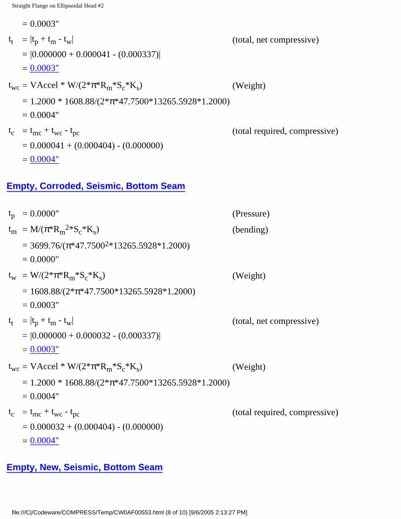
tt = |tp + tm - tw| (total, net compressive)
= |0.000000 + 0.000041 - (0.000337)|
= 0.0003"
twc = VAccel * W/(2*π*Rm*Sc*Ks) (Weight)
= 1.2000 * 1608.88/(2*π*47.7500*13265.5928*1.2000)
= 0.0004"
tc = tmc + twc - tpc (total required, compressive)
= 0.000041 + (0.000404) - (0.000000)
= 0.0004"
Empty, Corroded, Seismic, Bottom Seam
tp = 0.0000" (Pressure)
tm = M/(π*Rm2*Sc*Ks) (bending)
= 3699.76/(π*47.75002*13265.5928*1.2000)
= 0.0000"
tw = W/(2*π*Rm*Sc*Ks) (Weight)
= 1608.88/(2*π*47.7500*13265.5928*1.2000)
= 0.0003"
tt = |tp + tm - tw| (total, net compressive)
= |0.000000 + 0.000032 - (0.000337)|
= 0.0003"
twc = VAccel * W/(2*π*Rm*Sc*Ks) (Weight)
= 1.2000 * 1608.88/(2*π*47.7500*13265.5928*1.2000)
= 0.0004"
tc = tmc + twc - tpc (total required, compressive)
= 0.000032 + (0.000404) - (0.000000)
= 0.0004"
Empty, New, Seismic, Bottom Seam
file:///C|/Codeware/COMPRESS/Temp/CW0AF00553.html (8 of 10) [9/6/2005 2:13:27 PM]

Straight Flange on Ellipsoidal Head #2
tp = 0.0000" (Pressure)
tm = M/(π*Rm2*Sc*Ks) (bending)
= 3699.76/(π*47.75002*13265.5928*1.2000)
= 0.0000"
tw = W/(2*π*Rm*Sc*Ks) (Weight)
= 1608.88/(2*π*47.7500*13265.5928*1.2000)
= 0.0003"
tt = |tp + tm - tw| (total, net compressive)
= |0.000000 + 0.000032 - (0.000337)|
= 0.0003"
twc = VAccel * W/(2*π*Rm*Sc*Ks) (Weight)
= 1.2000 * 1608.88/(2*π*47.7500*13265.5928*1.2000)
= 0.0004"
tc = tmc + twc - tpc (total required, compressive)
= 0.000032 + (0.000404) - (0.000000)
= 0.0004"
Vacuum, Seismic, Bottom Seam
tp = P*R/(2*Sc*Ks + 0.40*|P|) (Pressure)
= -15.0000*47.5000/(2*13265.5928*1.2000 + 0.40*|15.0000|)
= -0.0224"
tm = M/(π*Rm2*Sc*Ks) (bending)
= 4623.04/(π*47.75002*13265.5928*1.2000)
= 0.0000"
tw = W/(2*π*Rm*Sc*Ks) (Weight)
= 1608.88/(2*π*47.7500*13265.5928*1.2000)
= 0.0003"
tt = |tp + tm - tw| (total, net compressive)
= |-0.022375 + 0.000041 - (0.000337)|
= 0.0227"
file:///C|/Codeware/COMPRESS/Temp/CW0AF00553.html (9 of 10) [9/6/2005 2:13:27 PM]

Straight Flange on Ellipsoidal Head #2
twc = VAccel * W/(2*π*Rm*Sc*Ks) (Weight)
= 1.2000 * 1608.88/(2*π*47.7500*13265.5928*1.2000)
= 0.0004"
tc = tmc + twc - tpc (total required, compressive)
= 0.000041 + (0.000404) - (-0.022375)
= 0.0228"
Hot Shut Down, Corroded, Weight & Eccentric Moments Only, Seismic, Bottom Seam
tp = 0.0000" (Pressure)
tm = M/(π*Rm2*Sc*Ks) (bending)
= 1384.25/(π*47.75002*13265.5928*1.0000)
= 0.0000"
tw = W/(2*π*Rm*Sc*Ks) (Weight)
= 1608.88/(2*π*47.7500*13265.5928*1.0000)
= 0.0004"
tt = |tp + tm - tw| (total, net compressive)
= |0.000000 + 0.000015 - (0.000404)|
= 0.0004"
twc = VAccel * W/(2*π*Rm*Sc*Ks) (Weight)
= 1.2000 * 1608.88/(2*π*47.7500*13265.5928*1.0000)
= 0.0005"
tc = tmc + twc - tpc (total required, compressive)
= 0.000015 + (0.000485) - (0.000000)
= 0.0005"
file:///C|/Codeware/COMPRESS/Temp/CW0AF00553.html (10 of 10) [9/6/2005 2:13:27 PM]

Straight Flange on Ellipsoidal Head #1
Straight Flange on Ellipsoidal Head #1
ASME Section VIII Division 1, 2001 Edition, A03 Addenda
Component: Straight FlangeMaterial specification: SA-516 70 (ASME II-D p. 14, ln. 31)Material impact test exemption temperature from Fig UCS-66 Curve B = -7 °FFig UCS-66.1 MDMT reduction = 31.7 °F, (coincident ratio = 0.682717)UCS-66 governing thickness = 0.5 in
Internal design pressure: P = 125 psi @ 300°FExternal design pressure: Pe = 15 psi @ 300°F
Static liquid head:
Ps =3.6819 psi(SG=1.0000, Hs=102.0000" Operating head)
Pth=3.6278 psi(SG=1.0000, Hs=100.5000", Horizontal test head)
Corrosion allowance: Inner C = 0.0000" Outer C = 0.0000"
Design MDMT = -20.00°F No impact test performedRated MDMT = -38.70°F Material is not normalized
Material is not produced to Fine Grain PracticePWHT is not performed
Radiography: Longitudinal joint - None UW-11(c) Type 1Circumferential joint - None UW-11(c) Type 1
Estimated weight: New = 84.9063 lb corr = 84.9063 lbCapacity: New = 61.3699 gal corr = 61.3699 gal
OD = 96.0000"Length Lc = 2.0000"
t = 0.5000"
Design thickness, (at 300.00°F) Appendix 1-1
t = P*Ro/(S*E + 0.40*P) + Corrosion
= 128.6819*48.0000/(20000.0000*0.70 + 0.40*128.6819) + 0.0000= 0.4396"
file:///C|/Codeware/COMPRESS/Temp/CW5FFBFD79.html (1 of 10) [9/6/2005 2:13:28 PM]

Straight Flange on Ellipsoidal Head #1
Maximum allowable working pressure, (at 300.00°F) Appendix 1-1
P = S*E*t/(Ro - 0.40*t) - Ps
= 20000.0000*0.70*0.5000 / (48.0000 - 0.40*0.5000) - 3.6819= 142.7616 psi
Maximum allowable pressure, (at 70.00°F) Appendix 1-1
P = S*E*t/(Ro - 0.40*t)
= 20000.0000*0.70*0.5000 / (48.0000 - 0.40*0.5000)= 146.4435 psi
External Pressure, (Corroded & at 300.00°F) UG-28(c)
L/Do = 111.8333/96.0000 = 1.1649
Do/t = 96.0000/0.329221 = 291.5970
From table G: A = 0.000228
From table CS-2: B = 3280.4565
Pa = 4*B/(3*(Do/t))
= 4*3280.4565/(3*(96.0000/0.329221))
= 15.0000 psi
Design thickness for external pressure Pa = 15.0000 psi
= t + Corrosion = 0.329221 + 0.0000 = 0.3292"
Maximum Allowable External Pressure, (Corroded & at 300.00°F) UG-28(c)
L/Do = 111.8333/96.0000 = 1.1649
Do/t = 96.0000/0.5000 = 192.0000
From table G: A = 0.000435
From table CS-2: B = 6256.9512
Pa = 4*B/(3*(Do/t))
= 4*6256.9512/(3*(96.0000/0.5000))
file:///C|/Codeware/COMPRESS/Temp/CW5FFBFD79.html (2 of 10) [9/6/2005 2:13:28 PM]

Straight Flange on Ellipsoidal Head #1
= 43.4510 psi
% Extreme fiber elongation - UCS-79(d)
= (50 * t / Rf) * (1 - Rf / Ro)
= (50 * 0.5000 / 47.7500) * (1 - 47.7500 / ∞)= 0.5236 %
Design thickness = 0.4396"
The governing condition is due to internal pressure.
The cylinder thickness of 0.5000" is adequate.
Thickness Required Due to Pressure + External Loads
ConditionPressure P ( psi)
Allowable Stress Before UG-23 Stress
Increase ( psi)Temperature
(°F)Corrosion
C (in)Load
Req'd Thk
Due to Tension
(in)
Req'd Thk Due to
Compression (in)St Sc
Operating, Hot & Corroded
125.00 20000.00 13265.59 300.00 0.0000 Seismic 0.1840 0.1827
Operating, Hot & New
125.00 20000.00 13265.59 300.00 0.0000 Seismic 0.1840 0.1827
Hot Shut Down, Corroded
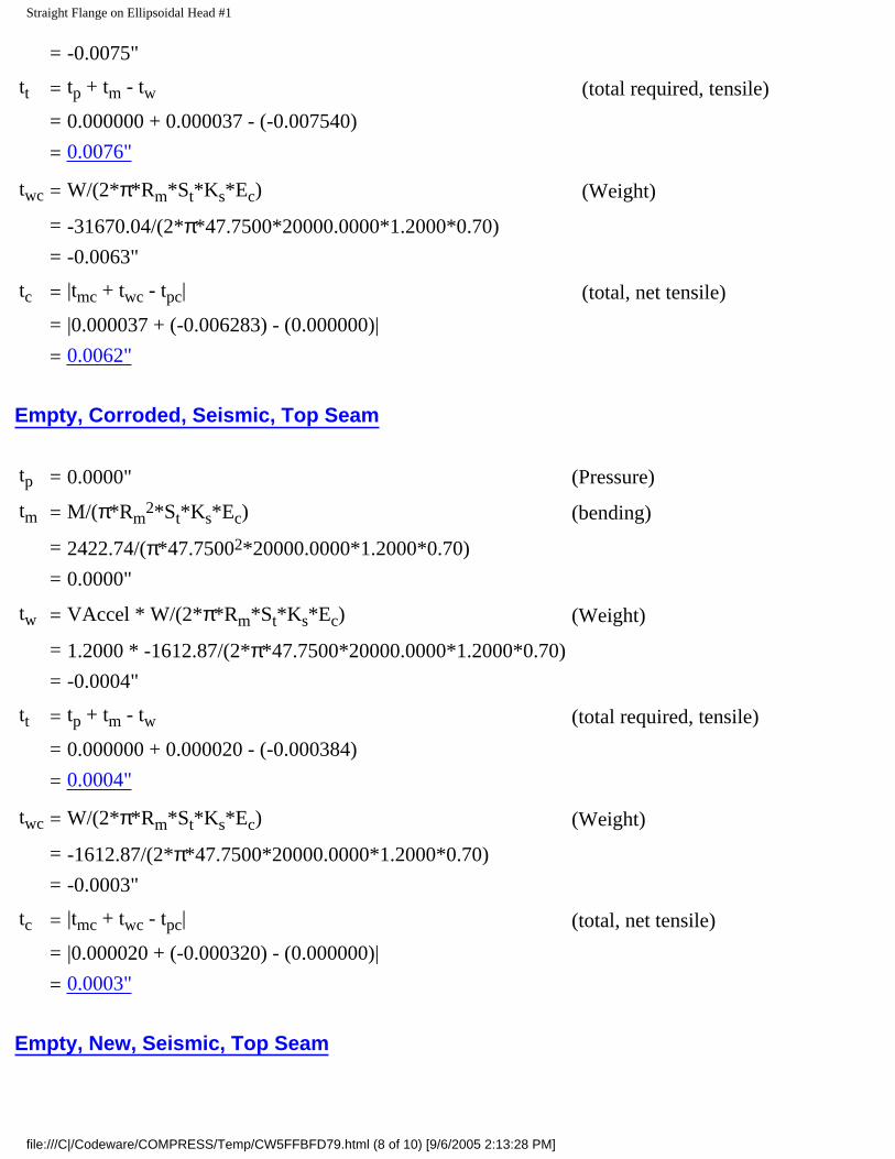
0.00 20000.00 13265.59 300.00 0.0000 Seismic 0.0076 0.0062
Hot Shut Down, New
0.00 20000.00 13265.59 300.00 0.0000 Seismic 0.0076 0.0062
Empty, Corroded 0.00 20000.00 13265.59 0.00 0.0000 Seismic 0.0004 0.0003
Empty, New 0.00 20000.00 13265.59 0.00 0.0000 Seismic 0.0004 0.0003
Vacuum -15.00 20000.00 13265.59 300.00 0.0000 Seismic 0.0144 0.0158
file:///C|/Codeware/COMPRESS/Temp/CW5FFBFD79.html (3 of 10) [9/6/2005 2:13:28 PM]

Straight Flange on Ellipsoidal Head #1
Hot Shut Down, Corroded, Weight & Eccentric Moments Only
0.00 20000.00 13265.59 300.00 0.0000 Weight 0.0091 0.0075
Allowable Compressive Stress, Hot and Corroded- ScHC, (table CS-2)
A = 0.125 / (Ro / t)
= 0.125 / (48.0000 / 0.5000)
= 0.001302
B = 13265.5928 psi
S = 20000.0000 / 1.0000
= 20000.0000 psi
ScHC = 13265.5928 psi
Allowable Compressive Stress, Hot and New- ScHN
ScHN = ScHC
= 13265.5928 psi
Allowable Compressive Stress, Cold and New- ScCN, (table CS-2)
A = 0.125 / (Ro / t)
= 0.125 / (48.0000 / 0.5000)
= 0.001302
B = 13265.5928 psi
S = 20000.0000 / 1.0000
= 20000.0000 psi
ScCN = 13265.5928 psi
file:///C|/Codeware/COMPRESS/Temp/CW5FFBFD79.html (4 of 10) [9/6/2005 2:13:28 PM]

Straight Flange on Ellipsoidal Head #1
Allowable Compressive Stress, Cold and Corroded- ScCC
ScCC = ScCN
= 13265.5928 psi
Allowable Compressive Stress, Vacuum and Corroded- ScVC, (table CS-2)
A = 0.125 / (Ro / t)
= 0.125 / (48.0000 / 0.5000)
= 0.001302
B = 13265.5928 psi
S = 20000.0000 / 1.0000
= 20000.0000 psi
ScVC = 13265.5928 psi
Operating, Hot & Corroded, Seismic, Top Seam
tp = P*R/(2*St*Ks*Ec + 0.40*|P|) (Pressure)
= 125.0000*47.5000/(2*20000.0000*1.2000*0.70 + 0.40*|125.0000|)
= 0.1764"
tm = M/(π*Rm2*St*Ks*Ec) (bending)
= 4409.57/(π*47.75002*20000.0000*1.2000*0.70)
= 0.0000"
tw = VAccel * W/(2*π*Rm*St*Ks*Ec) (Weight)
= 1.2000 * -31670.04/(2*π*47.7500*20000.0000*1.2000*0.70)
= -0.0075"
tt = tp + tm - tw (total required, tensile)
= 0.176449 + 0.000037 - (-0.007540)
= 0.1840"
twc = W/(2*π*Rm*St*Ks*Ec) (Weight)
= -31670.04/(2*π*47.7500*20000.0000*1.2000*0.70)
= -0.0063"
file:///C|/Codeware/COMPRESS/Temp/CW5FFBFD79.html (5 of 10) [9/6/2005 2:13:28 PM]

Straight Flange on Ellipsoidal Head #1
tc = |tmc + twc - tpc| (total, net tensile)
= |0.000037 + (-0.006283) - (0.176449)|
= 0.1827"
Maximum allowable working pressure, Longitudinal Stress
P = 2*St*Ks*Ec*(t-tm+tw) / (R - 0.40*(t-tm+tw))
=2*20000.0000*1.2000*0.70*(0.5000-0.000037+(-0.006283)) / (47.5000 - 0.40*(0.5000-0.000037+(-0.006283)))
= 350.6716 psi
Operating, Hot & New, Seismic, Top Seam
tp = P*R/(2*St*Ks*Ec + 0.40*|P|) (Pressure)
= 125.0000*47.5000/(2*20000.0000*1.2000*0.70 + 0.40*|125.0000|)
= 0.1764"
tm = M/(π*Rm2*St*Ks*Ec) (bending)
= 4409.57/(π*47.75002*20000.0000*1.2000*0.70)
= 0.0000"
tw = VAccel * W/(2*π*Rm*St*Ks*Ec) (Weight)
= 1.2000 * -31670.04/(2*π*47.7500*20000.0000*1.2000*0.70)
= -0.0075"
tt = tp + tm - tw (total required, tensile)
= 0.176449 + 0.000037 - (-0.007540)
= 0.1840"
twc = W/(2*π*Rm*St*Ks*Ec) (Weight)
= -31670.04/(2*π*47.7500*20000.0000*1.2000*0.70)
= -0.0063"
tc = |tmc + twc - tpc| (total, net tensile)
= |0.000037 + (-0.006283) - (0.176449)|
= 0.1827"
Maximum allowable working pressure, Longitudinal Stress
file:///C|/Codeware/COMPRESS/Temp/CW5FFBFD79.html (6 of 10) [9/6/2005 2:13:28 PM]

Straight Flange on Ellipsoidal Head #1
P = 2*St*Ks*Ec*(t-tm+tw) / (R - 0.40*(t-tm+tw))
=2*20000.0000*1.2000*0.70*(0.5000-0.000037+(-0.006283)) / (47.5000 - 0.40*(0.5000-0.000037+(-0.006283)))
= 350.6716 psi
Hot Shut Down, Corroded, Seismic, Top Seam
tp = 0.0000" (Pressure)
tm = M/(π*Rm2*St*Ks*Ec) (bending)
= 4409.57/(π*47.75002*20000.0000*1.2000*0.70)
= 0.0000"
tw = VAccel * W/(2*π*Rm*St*Ks*Ec) (Weight)
= 1.2000 * -31670.04/(2*π*47.7500*20000.0000*1.2000*0.70)
= -0.0075"
tt = tp + tm - tw (total required, tensile)
= 0.000000 + 0.000037 - (-0.007540)
= 0.0076"
twc = W/(2*π*Rm*St*Ks*Ec) (Weight)
= -31670.04/(2*π*47.7500*20000.0000*1.2000*0.70)
= -0.0063"
tc = |tmc + twc - tpc| (total, net tensile)
= |0.000037 + (-0.006283) - (0.000000)|
= 0.0062"
Hot Shut Down, New, Seismic, Top Seam
tp = 0.0000" (Pressure)
tm = M/(π*Rm2*St*Ks*Ec) (bending)
= 4409.57/(π*47.75002*20000.0000*1.2000*0.70)
= 0.0000"
tw = VAccel * W/(2*π*Rm*St*Ks*Ec) (Weight)
= 1.2000 * -31670.04/(2*π*47.7500*20000.0000*1.2000*0.70)
file:///C|/Codeware/COMPRESS/Temp/CW5FFBFD79.html (7 of 10) [9/6/2005 2:13:28 PM]
Straight Flange on Ellipsoidal Head #1
= -0.0075"
tt = tp + tm - tw (total required, tensile)
= 0.000000 + 0.000037 - (-0.007540)
= 0.0076"
twc = W/(2*π*Rm*St*Ks*Ec) (Weight)
= -31670.04/(2*π*47.7500*20000.0000*1.2000*0.70)
= -0.0063"
tc = |tmc + twc - tpc| (total, net tensile)
= |0.000037 + (-0.006283) - (0.000000)|
= 0.0062"
Empty, Corroded, Seismic, Top Seam
tp = 0.0000" (Pressure)
tm = M/(π*Rm2*St*Ks*Ec) (bending)
= 2422.74/(π*47.75002*20000.0000*1.2000*0.70)
= 0.0000"
tw = VAccel * W/(2*π*Rm*St*Ks*Ec) (Weight)
= 1.2000 * -1612.87/(2*π*47.7500*20000.0000*1.2000*0.70)
= -0.0004"
tt = tp + tm - tw (total required, tensile)
= 0.000000 + 0.000020 - (-0.000384)
= 0.0004"
twc = W/(2*π*Rm*St*Ks*Ec) (Weight)
= -1612.87/(2*π*47.7500*20000.0000*1.2000*0.70)
= -0.0003"
tc = |tmc + twc - tpc| (total, net tensile)
= |0.000020 + (-0.000320) - (0.000000)|
= 0.0003"
Empty, New, Seismic, Top Seam
file:///C|/Codeware/COMPRESS/Temp/CW5FFBFD79.html (8 of 10) [9/6/2005 2:13:28 PM]

Straight Flange on Ellipsoidal Head #1
tp = 0.0000" (Pressure)
tm = M/(π*Rm2*St*Ks*Ec) (bending)
= 2422.74/(π*47.75002*20000.0000*1.2000*0.70)
= 0.0000"
tw = VAccel * W/(2*π*Rm*St*Ks*Ec) (Weight)
= 1.2000 * -1612.87/(2*π*47.7500*20000.0000*1.2000*0.70)
= -0.0004"
tt = tp + tm - tw (total required, tensile)
= 0.000000 + 0.000020 - (-0.000384)
= 0.0004"
twc = W/(2*π*Rm*St*Ks*Ec) (Weight)
= -1612.87/(2*π*47.7500*20000.0000*1.2000*0.70)
= -0.0003"
tc = |tmc + twc - tpc| (total, net tensile)
= |0.000020 + (-0.000320) - (0.000000)|
= 0.0003"
Vacuum, Seismic, Top Seam
tp = P*R/(2*Sc*Ks + 0.40*|P|) (Pressure)
= -15.0000*47.5000/(2*13265.5928*1.2000 + 0.40*|15.0000|)
= -0.0224"
tm = M/(π*Rm2*Sc*Ks) (bending)
= 4409.57/(π*47.75002*13265.5928*1.2000)
= 0.0000"
tw = VAccel * W/(2*π*Rm*Sc*Ks) (Weight)
= 1.2000 * -31670.04/(2*π*47.7500*13265.5928*1.2000)
= -0.0080"
tt = |tp + tm - tw| (total, net compressive)
= |-0.022375 + 0.000039 - (-0.007957)|
= 0.0144"
file:///C|/Codeware/COMPRESS/Temp/CW5FFBFD79.html (9 of 10) [9/6/2005 2:13:28 PM]

Straight Flange on Ellipsoidal Head #1
twc = W/(2*π*Rm*Sc*Ks) (Weight)
= -31670.04/(2*π*47.7500*13265.5928*1.2000)
= -0.0066"
tc = tmc + twc - tpc (total required, compressive)
= 0.000039 + (-0.006631) - (-0.022375)
= 0.0158"
Hot Shut Down, Corroded, Weight & Eccentric Moments Only, Seismic, Top Seam
tp = 0.0000" (Pressure)
tm = M/(π*Rm2*St*Ks*Ec) (bending)
= 1459.96/(π*47.75002*20000.0000*1.0000*0.70)
= 0.0000"
tw = VAccel * W/(2*π*Rm*St*Ks*Ec) (Weight)
= 1.2000 * -31670.04/(2*π*47.7500*20000.0000*1.0000*0.70)
= -0.0090"
tt = tp + tm - tw (total required, tensile)
= 0.000000 + 0.000015 - (-0.009048)
= 0.0091"
twc = W/(2*π*Rm*St*Ks*Ec) (Weight)
= -31670.04/(2*π*47.7500*20000.0000*1.0000*0.70)
= -0.0075"
tc = |tmc + twc - tpc| (total, net tensile)
= |0.000015 + (-0.007540) - (0.000000)|
= 0.0075"
file:///C|/Codeware/COMPRESS/Temp/CW5FFBFD79.html (10 of 10) [9/6/2005 2:13:28 PM]

Ellipsoidal Head #1
Ellipsoidal Head #1
ASME Section VIII, Division 1, 2001 Edition, A03 Addenda
Component: Ellipsoidal Head Material Specification: SA-516 70 (ASME II-D p.14, ln. 31)Material impact test exemption temperature from Fig UCS-66 Curve B = -7 °FFig UCS-66.1 MDMT reduction = 31.6 °F, (coincident ratio = 0.684324)UCS-66 governing thickness = 0.5 in
Internal design pressure: P = 125 psi @ 300 °FExternal design pressure: Pe = 15 psi @ 300 °F
Static liquid head:
Ps= 4.5392 psi (SG=1, Hs=126.25" Operating head)
Pth= 3.6278 psi (SG=1, Hs=100.5" Horizontal test head)
Corrosion allowance: Inner C = 0" Outer C = 0"
Design MDMT = -20°F No impact test performed Rated MDMT = -38.6°F Material is not normalized
Material is not produced to fine grain practice PWHT is not performed Do not Optimize MDMT / Find MAWP
Radiography: Category A joints - None UW-11(c) Type 1 Head to shell seam - None UW-11(c) Type 1
Estimated weight*: new = 1,572.20 lb corr = 1,572.20 lb Capacity*: new = 547.2 US gal corr = 547.2 US gal* includes straight flange
Outer diameter = 96"Minimum head thickness = 0.5"Head ratio D/2h = 2 (new)Head ratio D/2h = 2 (corroded)Straight flange length Lsf = 2"Nominal straight flange thickness tsf = 0.5"
file:///C|/Codeware/COMPRESS/Temp/CW7B475AA6.html (1 of 4) [9/6/2005 2:13:28 PM]

Ellipsoidal Head #1
Insulation thk*: 0" density: 0 lb/ft3 weight: 0 lb Insulation support ring spacing:
0" individual weight: 0 lb total weight: 0 lb
Lining/ref thk*: 0" density: 0 lb/ft3 weight: 0 lb* includes straight flange if applicable
Results Summary
The governing condition is internal pressure.Minimum thickness per UG-16 = 0.0625" + 0" = 0.0625"Design thickness due to internal pressure (t) = 0.4405"Design thickness due to external pressure (te) = 0.247"
Maximum allowable working pressure (MAWP) = 142.6742 psi
Maximum allowable pressure (MAP) = 147.2135 psi
Maximum allowable external pressure (MAEP) = 61.6617 psi
K (Corroded)
K = (1/6)*[2 + (D / (2*h))2]= (1/6)*[2 + (95 / (2*23.75))2]= 1
K (New)
K = (1/6)*[2 + (D / (2*h))2]= (1/6)*[2 + (95 / (2*23.75))2]= 1
Design thickness for internal pressure, (Corroded at 300 °F) Appendix 1-4(c)
t = P*Do*K / (2*S*E + 2*P*(K - 0.1)) + Corrosion
= 129.5392*96*1 / (2*20000*0.7 + 2*129.5392*(1 - 0.1)) + 0= 0.4405"
The head internal pressure design thickness is 0.4405".
Maximum allowable working pressure, (Corroded at 300 °F) Appendix 1-4(c)
P = 2*S*E*t / (K*Do - 2*t*(K - 0.1)) - Ps
file:///C|/Codeware/COMPRESS/Temp/CW7B475AA6.html (2 of 4) [9/6/2005 2:13:28 PM]

Ellipsoidal Head #1
= 2*20000*0.7*0.5 / (1*96 - 2*0.5*(1 - 0.1)) - 4.5392= 142.6742 psi
The maximum allowable working pressure (MAWP) is 142.6742 psi.
Maximum allowable pressure, (New at 70 °F) Appendix 1-4(c)
P = 2*S*E*t / (K*Do - 2*t*(K - 0.1)) - Ps
= 2*20000*0.7*0.5 / (1*96 - 2*0.5*(1 - 0.1)) - 0= 147.2135 psi
The maximum allowable pressure (MAP) is 147.2135 psi.
Design thickness for external pressure, (Corroded at 300 °F) UG-33(d)
Equivalent outside spherical radius (Ro)
Ro = Ko*Do
= 0.8907 * 96 = 85.5093 in
A = 0.125 / (Ro/t)
= 0.125 / (85.5093/0.246972) = 0.000361
From Table CS-2: B=5,193.4536 psi
Pa = B/(Ro/t)
= 5,193.454/(85.5093/0.246972) = 15 psi
t = 0.247" + Corrosion = 0.247" + 0" = 0.247"
Check the external pressure per UG-33(a)(1) Appendix 1-4(c)
t = 1.67*Pe*Do*K / (2*S*E + 2*1.67*Pe*(K - 0.1)) + Corrosion
= 1.67*15*96*1 / (2*20000*1 + 2*1.67*15*(1 - 0.1)) + 0= 0.0601"
The head external pressure design thickness (te) is 0.246972".
Maximum Allowable External Pressure, (Corroded at 300 °F) UG-33(d)
file:///C|/Codeware/COMPRESS/Temp/CW7B475AA6.html (3 of 4) [9/6/2005 2:13:28 PM]

Ellipsoidal Head #1
Equivalent outside spherical radius (Ro)
Ro = Ko*Do
= 0.8907 * 96 = 85.5093 in
A = 0.125 / (Ro/t)
= 0.125 / (85.5093/0.5) = 0.000731
From Table CS-2: B=10,545.2891 psi
Pa = B/(Ro/t)
= 10,545.29/(85.5093/0.5) = 61.6617 psi
Check the Maximum External Pressure, UG-33(a)(1) Appendix 1-4(c)
P = 2*S*E*t / ((K*Do - 2*t*(K - 0.1))*1.67) - Ps2
= 2*20000*1*0.5 / ((1*96 - 2*0.5*(1 - 0.1))*1.67) - 0= 125.9311 psi
The maximum allowable external pressure (MAEP) is 61.6617 psi.
% Extreme fiber elongation - UCS-79(d)
= (75*t / Rf)*(1 - Rf / Ro)
= (75*0.5 / 16.4)*(1 - 16.4 / ∞)
= 2.2866%
The extreme fiber elongation does not exceed 5%.
file:///C|/Codeware/COMPRESS/Temp/CW7B475AA6.html (4 of 4) [9/6/2005 2:13:28 PM]

Nozzle #1 (N1)
Nozzle #1 (N1)
ASME Section VIII Division 1, 2001 Edition, A03 Addenda
tw(lower) = 0.1870 in
Leg41 = 0.2500 in
Note: round inside edges per UG-76(c)
Located on: Ellipsoidal Head #1Liquid static head included: 4.7648 psiNozzle material specification: SA-106 B Smls pipe (ASME II-D p. 10, ln. 15)Nozzle longitudinal joint efficiency: 1.00Nozzle description: 2.500" Sch 40 (Std)Flange description: 2.5 inch 150# WN A105Bolt Material: SA-193 B7 Bolt <= 2 1/2Flange rated MDMT: -55.00 °F(UCS-66(b)(1)(b))Liquid static head on flange: 4.7829 psiASME B16.5 flange rating MAWP: 230.00 psi @ 300.00°FASME B16.5 flange rating MAP: 285.00 psi @ 70.00°FASME B16.5 flange hydro test: 450.00 psi @ 70.00°FNozzle orientation: 0 °Calculated as hillside: noLocal vessel minimum thickness: 0.5000 inEnd of nozzle to datum line: -32.5000 inNozzle inside diameter, new: 2.4690 inNozzle nominal wall thickness: 0.2030 inNozzle corrosion allowance: 0.0000 inProjection available outside vessel, Lpr: 6.2609 inDistance to head center, R: 0.0000 in
file:///C|/Codeware/COMPRESS/Temp/CW342106F3.html (1 of 10) [9/6/2005 2:13:29 PM]

Nozzle #1 (N1)
Reinforcement Calculations for Internal Pressure
Available reinforcement per UG-37 governs the MAWP of this nozzle.
UG-37 Area Calculation Summary (in2)For P = 174.22 psi @ 300.00 °F
UG-45 Nozzle WallThickness Summary (in)The nozzle passes UG-45
Arequired
Aavailable
A1 A2 A3 A5Awelds
treq tmin
This nozzle is exempt from area calculations per UG-36(c)(3)(a) 0.1776 0.1776
Weld Failure Path Analysis Summary
The nozzle is exempt from weld strength calculations per UW-15(b)(2)
UW-16 Weld Sizing Summary
Weld descriptionRequired weldthroat size (in)
Actual weldthroat size (in)
Status
Nozzle to shell fillet (Leg41) 0.1421 0.1750 weld size is adequate
Nozzle to shell groove (Lower) 0.1421 0.1870 weld size is adequate
Calculations for internal pressure 174.22 psi @ 300.00 °F
Fig UCS-66.2 general note (1) applies.
Nozzle is impact test exempt per UCS-66(d)(NPS 4 or smaller pipe).
Nozzle UCS-66 governing thk: 0.1776 inNozzle rated MDMT: -155.00 °F
Limits of reinforcement per UG-40
Parallel to the vessel wall: d = 2.4690 in
Normal to the vessel wall outside: 2.5*(tn - Cn) + te = 0.5075 in
Nozzle required thickness per UG-27(c)(1)
file:///C|/Codeware/COMPRESS/Temp/CW342106F3.html (2 of 10) [9/6/2005 2:13:29 PM]

Nozzle #1 (N1)
trn = P*Rn/(Sn*E - 0.6*P)
= 174.2156*1.2345/(17,100.00*1 - 0.6*174.2156)= 0.0127 in
Required thickness tr from UG-37(a)(3)
tr = P*K1*Do/(2*S*E + 0.8*P)
= 174.2156*0.9*96/(2*20,000.00*1 + 0.8*174.2156)= 0.3750 in
This opening does not require reinforcement per UG-36(c)(3)(a)
Area calculations for weld failure path analysis
Allowable stresses: Sn = 17,100.00, Sv = 20,000.00 psi
fr1 = lesser of 1 or Sn/Sv = 0.855
fr2 = lesser of 1 or Sn/Sv = 0.855
A = d*tr*F + 2*tn*tr*F*(1 - fr1)
= 2.469*0.375*1 + 2*0.203*0.375*1*(1 - 0.855)= 0.9480 in2
A1 = larger of the following= 0.3013 in2
= d*(E1*t - F*tr) - 2*tn*(E1*t - F*tr)*(1 - fr1)
= 2.469*(1*0.5 - 1*0.375) - 2*0.203*(1*0.5 - 1*0.375)*(1 - 0.855)= 0.3013 in2
= 2*(t + tn)*(E1*t - F*tr) - 2*tn*(E1*t - F*tr)*(1 - fr1)
= 2*(0.5 + 0.203)*(1*0.5 - 1*0.375) - 2*0.203*(1*0.5 - 1*0.375)*(1 - 0.855)= 0.1684 in2
A2 = smaller of the following= 0.1651 in2
= 5*(tn - trn)*fr2*t
= 5*(0.203 - 0.0127)*0.855*0.5= 0.4068 in2
= 5*(tn - trn)*fr2*tn= 5*(0.203 - 0.0127)*0.855*0.203
file:///C|/Codeware/COMPRESS/Temp/CW342106F3.html (3 of 10) [9/6/2005 2:13:29 PM]

Nozzle #1 (N1)
= 0.1651 in2
A41 = Leg2*fr2
= 0.252*0.855 =0.0534 in2
UW-16(d) Weld Check
tmin = lesser of 0.75 or tn or t = 0.2030 in
t1(min) or t2(min) = lesser of 0.25 or 0.7*tmin = 0.1421 in
t1(actual) = 0.7*Leg = 0.7*0.25 = 0.175 in
The weld size t1 is satisfactory.
t2(actual) = 0.187 in
The weld size t2 is satisfactory.
t1 + t2 = 0.362 >= 1.25*tmin
The combined weld sizes for t1 and t2 are satisfactory.
UG-45 Nozzle Neck Thickness Check
Interpretation VIII-1-83-66 has been applied.
Wall thickness per UG-45(a): tr1 = 0.0127 in (E =1)
Wall thickness per UG-45(b)(1): tr2 = 0.4149 in
Wall thickness per UG-16(b): tr3 = 0.0625 in
Standard wall pipe per UG-45(b)(4): tr4 = 0.1776 in
The greater of tr2 or tr3: tr5 = 0.4149 in
The lesser of tr4 or tr5: tr6 = 0.1776 in
Required per UG-45 is the larger of tr1 or tr6 = 0.1776 in
Available nozzle wall thickness new, tn = 0.8750*0.2030 = 0.1776 in
The nozzle neck thickness is adequate.
Reinforcement Calculations for MAP
Available reinforcement per UG-37 governs the MAP of this nozzle.
file:///C|/Codeware/COMPRESS/Temp/CW342106F3.html (4 of 10) [9/6/2005 2:13:29 PM]

Nozzle #1 (N1)
UG-37 Area Calculation Summary (in2)For P = 174.20 psi @ 70.00 °F
UG-45 Nozzle WallThickness Summary (in)The nozzle passes UG-45
Arequired
Aavailable
A1 A2 A3 A5Awelds
treq tmin
This nozzle is exempt from area calculations per UG-36(c)(3)(a) 0.1776 0.1776
Weld Failure Path Analysis Summary
The nozzle is exempt from weld strength calculations per UW-15(b)(2)
UW-16 Weld Sizing Summary
Weld descriptionRequired weldthroat size (in)
Actual weldthroat size (in)
Status
Nozzle to shell fillet (Leg41) 0.1421 0.1750 weld size is adequate
Nozzle to shell groove (Lower) 0.1421 0.1870 weld size is adequate
Calculations for internal pressure 174.20 psi @ 70.00 °F
Limits of reinforcement per UG-40
Parallel to the vessel wall: d = 2.4690 in
Normal to the vessel wall outside: 2.5*(tn - Cn) + te = 0.5075 in
Nozzle required thickness per UG-27(c)(1)
trn = P*Rn/(Sn*E - 0.6*P)
= 174.1972*1.2345/(17,100.00*1 - 0.6*174.1972)= 0.0127 in
Required thickness tr from UG-37(a)(3)
tr = P*K1*Do/(2*S*E + 0.8*P)
= 174.1972*0.9*96/(2*20,000.00*1 + 0.8*174.1972)= 0.3750 in
This opening does not require reinforcement per UG-36(c)(3)(a)
file:///C|/Codeware/COMPRESS/Temp/CW342106F3.html (5 of 10) [9/6/2005 2:13:29 PM]

Nozzle #1 (N1)
Area calculations for weld failure path analysis
Allowable stresses: Sn = 17,100.00, Sv = 20,000.00 psi
fr1 = lesser of 1 or Sn/Sv = 0.855
fr2 = lesser of 1 or Sn/Sv = 0.855
A = d*tr*F + 2*tn*tr*F*(1 - fr1)
= 2.469*0.37496*1 + 2*0.203*0.37496*1*(1 - 0.855)= 0.9479 in2
A1 = larger of the following= 0.3014 in2
= d*(E1*t - F*tr) - 2*tn*(E1*t - F*tr)*(1 - fr1)
= 2.469*(1*0.5 - 1*0.37496) - 2*0.203*(1*0.5 - 1*0.37496)*(1 - 0.855)= 0.3014 in2
= 2*(t + tn)*(E1*t - F*tr) - 2*tn*(E1*t - F*tr)*(1 - fr1)
= 2*(0.5 + 0.203)*(1*0.5 - 1*0.37496) - 2*0.203*(1*0.5 - 1*0.37496)*(1 - 0.855)= 0.1684 in2
A2 = smaller of the following= 0.1651 in2
= 5*(tn - trn)*fr2*t
= 5*(0.203 - 0.0127)*0.855*0.5= 0.4068 in2
= 5*(tn - trn)*fr2*tn= 5*(0.203 - 0.0127)*0.855*0.203= 0.1651 in2
A41 = Leg2*fr2
= 0.252*0.855 =0.0534 in2
UW-16(d) Weld Check
tmin = lesser of 0.75 or tn or t = 0.2030 in
t1(min) or t2(min) = lesser of 0.25 or 0.7*tmin = 0.1421 in
t1(actual) = 0.7*Leg = 0.7*0.25 = 0.175 in
file:///C|/Codeware/COMPRESS/Temp/CW342106F3.html (6 of 10) [9/6/2005 2:13:29 PM]
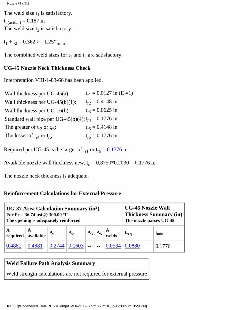
Nozzle #1 (N1)
The weld size t1 is satisfactory.
t2(actual) = 0.187 in
The weld size t2 is satisfactory.
t1 + t2 = 0.362 >= 1.25*tmin
The combined weld sizes for t1 and t2 are satisfactory.
UG-45 Nozzle Neck Thickness Check
Interpretation VIII-1-83-66 has been applied.
Wall thickness per UG-45(a): tr1 = 0.0127 in (E =1)
Wall thickness per UG-45(b)(1): tr2 = 0.4148 in
Wall thickness per UG-16(b): tr3 = 0.0625 in
Standard wall pipe per UG-45(b)(4): tr4 = 0.1776 in
The greater of tr2 or tr3: tr5 = 0.4148 in
The lesser of tr4 or tr5: tr6 = 0.1776 in
Required per UG-45 is the larger of tr1 or tr6 = 0.1776 in
Available nozzle wall thickness new, tn = 0.8750*0.2030 = 0.1776 in
The nozzle neck thickness is adequate.
Reinforcement Calculations for External Pressure
UG-37 Area Calculation Summary (in2)For Pe = 36.74 psi @ 300.00 °FThe opening is adequately reinforced
UG-45 Nozzle WallThickness Summary (in)The nozzle passes UG-45
Arequired
Aavailable
A1 A2 A3 A5Awelds
treq tmin
0.4881 0.4881 0.2744 0.1603 -- -- 0.0534 0.0880 0.1776
Weld Failure Path Analysis Summary
Weld strength calculations are not required for external pressure
file:///C|/Codeware/COMPRESS/Temp/CW342106F3.html (7 of 10) [9/6/2005 2:13:29 PM]

Nozzle #1 (N1)
UW-16 Weld Sizing Summary
Weld descriptionRequired weldthroat size (in)
Actual weldthroat size (in)
Status
Nozzle to shell fillet (Leg41) 0.1421 0.1750 weld size is adequate
Nozzle to shell groove (Lower) 0.1421 0.1870 weld size is adequate
Calculations for external pressure 36.74 psi @ 300.00 °F
Limits of reinforcement per UG-40
Parallel to the vessel wall: d = 2.4690 in
Normal to the vessel wall outside: 2.5*(tn - Cn) + te = 0.5075 in
Nozzle required thickness per UG-28 trn = 0.0182 in
From UG-37(d)(1) required thickness tr = 0.3862 in
Area required per UG-37(d)(1)
Allowable stresses: Sn = 17,100.00, Sv = 20,000.00 psi
fr1 = lesser of 1 or Sn/Sv = 0.855
fr2 = lesser of 1 or Sn/Sv = 0.855
A = 0.5*(d*tr*F + 2*tn*tr*F*(1 - fr1))
= 0.5*(2.469*0.38616*1 + 2*0.203*0.38616*1*(1 - 0.855))= 0.4881 in2
Area available from FIG. UG-37.1
A1 = larger of the following= 0.2744 in2
= d*(E1*t - F*tr) - 2*tn*(E1*t - F*tr)*(1 - fr1)
= 2.469*(1*0.5 - 1*0.38616) - 2*0.203*(1*0.5 - 1*0.38616)*(1 - 0.855)= 0.2744 in2
= 2*(t + tn)*(E1*t - F*tr) - 2*tn*(E1*t - F*tr)*(1 - fr1)
file:///C|/Codeware/COMPRESS/Temp/CW342106F3.html (8 of 10) [9/6/2005 2:13:29 PM]

Nozzle #1 (N1)
= 2*(0.5 + 0.203)*(1*0.5 - 1*0.38616) - 2*0.203*(1*0.5 - 1*0.38616)*(1 - 0.855)= 0.1534 in2
A2 = smaller of the following= 0.1603 in2
= 5*(tn - trn)*fr2*t
= 5*(0.203 - 1.824298E-02)*0.855*0.5= 0.3949 in2
= 5*(tn - trn)*fr2*tn= 5*(0.203 - 1.824298E-02)*0.855*0.203= 0.1603 in2
A41 = Leg2*fr2
= 0.252*0.855 =0.0534 in2
Area = A1 + A2 + A41
= 0.2744 + 0.1603 + 0.0534= 0.4881 in2
As Area >= A the reinforcement is adequate.
UW-16(d) Weld Check
tmin = lesser of 0.75 or tn or t = 0.2030 in
t1(min) or t2(min) = lesser of 0.25 or 0.7*tmin = 0.1421 in
t1(actual) = 0.7*Leg = 0.7*0.25 = 0.175 in
The weld size t1 is satisfactory.
t2(actual) = 0.187 in
The weld size t2 is satisfactory.
t1 + t2 = 0.362 >= 1.25*tmin
The combined weld sizes for t1 and t2 are satisfactory.
UG-45 Nozzle Neck Thickness Check
Interpretation VIII-1-83-66 has been applied.
Wall thickness per UG-45(a): tr1 = 0.0182 in
Wall thickness per UG-45(b)(2): tr2 = 0.0880 in
file:///C|/Codeware/COMPRESS/Temp/CW342106F3.html (9 of 10) [9/6/2005 2:13:29 PM]

Nozzle #1 (N1)
Wall thickness per UG-16(b): tr3 = 0.0625 in
Standard wall pipe per UG-45(b)(4): tr4 = 0.1776 in
The greater of tr2 or tr3: tr5 = 0.0880 in
The lesser of tr4 or tr5: tr6 = 0.0880 in
Required per UG-45 is the larger of tr1 or tr6 = 0.0880 in
Available nozzle wall thickness new, tn = 0.8750*0.2030 = 0.1776 in
The nozzle neck thickness is adequate.
External Pressure, (Corroded & at 300.00°F) UG-28(c)
L/Do = 6.2609/2.8750 = 2.1777
Do/t = 2.8750/0.018243 = 157.5949
From table G: A = 0.000302
From table CS-2: B = 4342.7334
Pa = 4*B/(3*(Do/t))
= 4*4342.7334/(3*(2.8750/0.018243))
= 36.7417 psi
Design thickness for external pressure Pa = 36.7417 psi
= t + Corrosion = 0.018243 + 0.0000 = 0.0182"
file:///C|/Codeware/COMPRESS/Temp/CW342106F3.html (10 of 10) [9/6/2005 2:13:29 PM]

Nozzle #2 (N2)
Nozzle #2 (N2)
ASME Section VIII Division 1, 2001 Edition, A03 Addenda
tw(lower) = 0.3750 in
Leg41 = 0.3750 in
Leg43 = 0.3750 in
hnew = 0.3750 in
Note: round inside edges per UG-76(c)
Located on: Cylinder #1Liquid static head included: 3.1134 psiNozzle material specification: SA-106 C Smls pipe (ASME II-D p. 18, ln. 1)Nozzle longitudinal joint efficiency: 1.00Nozzle description: 18" Sch 60Nozzle orientation: 180 °Local vessel minimum thickness: 0.5000 inNozzle center line offset to datum line: 22.0000 inEnd of nozzle to shell center: 51.1250 inNozzle inside diameter, new: 16.5000 inNozzle nominal wall thickness: 0.7500 inNozzle corrosion allowance: 0.0000 inProjection available outside vessel, Lpr: 3.1250 in
Reinforcement Calculations for Internal Pressure
Available reinforcement per UG-37 governs the MAWP of this nozzle.
UG-37 Area Calculation Summary (in2)For P = 137.00 psi @ 300.00 °FThe opening is adequately reinforced
UG-45 Nozzle WallThickness Summary (in)The nozzle passes UG-45
file:///C|/Codeware/COMPRESS/Temp/CW7430761C.html (1 of 13) [9/6/2005 2:13:30 PM]

Nozzle #2 (N2)
Arequired
Aavailable
A1 A2 A3 A5Awelds
treq tmin
5.4105 5.4165 2.8395 1.7333 0.5625 -- 0.2812 0.0625 0.6563
Weld Failure Path Analysis Summary (lbf)All failure paths are stronger than the applicable weld loads
Weld loadW
Weld loadW1-1
Path 1-1strength
Weld loadW2-2
Path 2-2strength
56,583.01 37,478.00 388,418.69 66,540.00 364,738.91
UW-16 Weld Sizing Summary
Weld descriptionRequired weldthroat size (in)
Actual weldthroat size (in)
Status
Nozzle to shell fillet (Leg41) 0.2500 0.2625 weld size is adequate
Nozzle to inside shell fillet (Leg43) 0.2500 0.2625(corroded)
weld size is adequate
Nozzle to shell groove (Lower) 0.3625 0.3750 weld size is adequate
Calculations for internal pressure 137.00 psi @ 300.00 °F
Fig UCS-66.2 general note (1) applies.
Nozzle impact test exemption temperature from Fig UCS-66 Curve B = -7 °FFig UCS-66.1 MDMT reduction = 40.6 °F, (coincident ratio = 0.5953).
Nozzle UCS-66 governing thk: 0.5000 inNozzle rated MDMT: -47.60 °F
Limits of reinforcement per UG-40
Parallel to the vessel wall: d = 16.5000 inNormal to the vessel wall outside: 2.5*(t - C) = 1.2500 inNormal to the vessel wall inside: 2.5*(t - C) = 1.2500 in
Nozzle required thickness per UG-27(c)(1)
file:///C|/Codeware/COMPRESS/Temp/CW7430761C.html (2 of 13) [9/6/2005 2:13:30 PM]

Nozzle #2 (N2)
trn = P*Rn/(Sn*E - 0.6*P)
= 137.0036*8.25/(20,000.00*1 - 0.6*137.0036)= 0.0567 in
Required thickness tr from UG-37(a)
tr = P*Ro/(S*E + 0.4*P)
= 137.0036*48/(20,000.00*1 + 0.4*137.0036)= 0.3279 in
Area required per UG-37(c)
Allowable stresses: Sn = 20,000.00, Sv = 20,000.00 psi
fr1 = lesser of 1 or Sn/Sv = 1
fr2 = lesser of 1 or Sn/Sv = 1
A = d*tr*F + 2*tn*tr*F*(1 - fr1)
= 16.5*0.32791*1 + 2*0.75*0.32791*1*(1 - 1)= 5.4105 in2
Area available from FIG. UG-37.1
A1 = larger of the following= 2.8395 in2
= d*(E1*t - F*tr) - 2*tn*(E1*t - F*tr)*(1 - fr1)
= 16.5*(1*0.5 - 1*0.32791) - 2*0.75*(1*0.5 - 1*0.32791)*(1 - 1)= 2.8395 in2
= 2*(t + tn)*(E1*t - F*tr) - 2*tn*(E1*t - F*tr)*(1 - fr1)
= 2*(0.5 + 0.75)*(1*0.5 - 1*0.32791) - 2*0.75*(1*0.5 - 1*0.32791)*(1 - 1)= 0.4302 in2
A2 = smaller of the following= 1.7333 in2
= 5*(tn - trn)*fr2*t
= 5*(0.75 - 0.0567)*1*0.5= 1.7333 in2
= 5*(tn - trn)*fr2*tn= 5*(0.75 - 0.0567)*1*0.75= 2.5999 in2
file:///C|/Codeware/COMPRESS/Temp/CW7430761C.html (3 of 13) [9/6/2005 2:13:30 PM]

Nozzle #2 (N2)
A3 = smaller of the following= 0.5625 in2
= 5*t*ti*fr2
= 5*0.5*0.75*1= 1.8750 in2
= 5*ti*ti*fr2
= 5*0.75*0.75*1= 2.8125 in2
= 2*h*ti*fr2
= 2*0.375*0.75*1= 0.5625 in2
A41 = Leg2*fr2
= 0.3752*1 =0.1406 in2
A43 = Leg2*fr2
= 0.3752*1 = 0.1406 in2
Area = A1 + A2 + A3 + A41 + A43
= 2.8395 + 1.7333 + 0.5625 + 0.1406 + 0.1406= 5.4165 in2
As Area >= A the reinforcement is adequate.
UW-16(d) Weld Check
tmin = lesser of 0.75 or tn or t = 0.5000 in
t1(min) or t2(min) = lesser of 0.25 or 0.7*tmin = 0.2500 in
t1(actual) = 0.7*Leg = 0.7*0.375 = 0.2625 in
The weld size t1 is satisfactory.
t2(actual) = 0.375 in
The weld size t2 is satisfactory.
t1 + t2 = 0.6375 >= 1.25*tmin
The combined weld sizes for t1 and t2 are satisfactory.
UG-45 Nozzle Neck Thickness Check (Access Opening)
file:///C|/Codeware/COMPRESS/Temp/CW7430761C.html (4 of 13) [9/6/2005 2:13:30 PM]
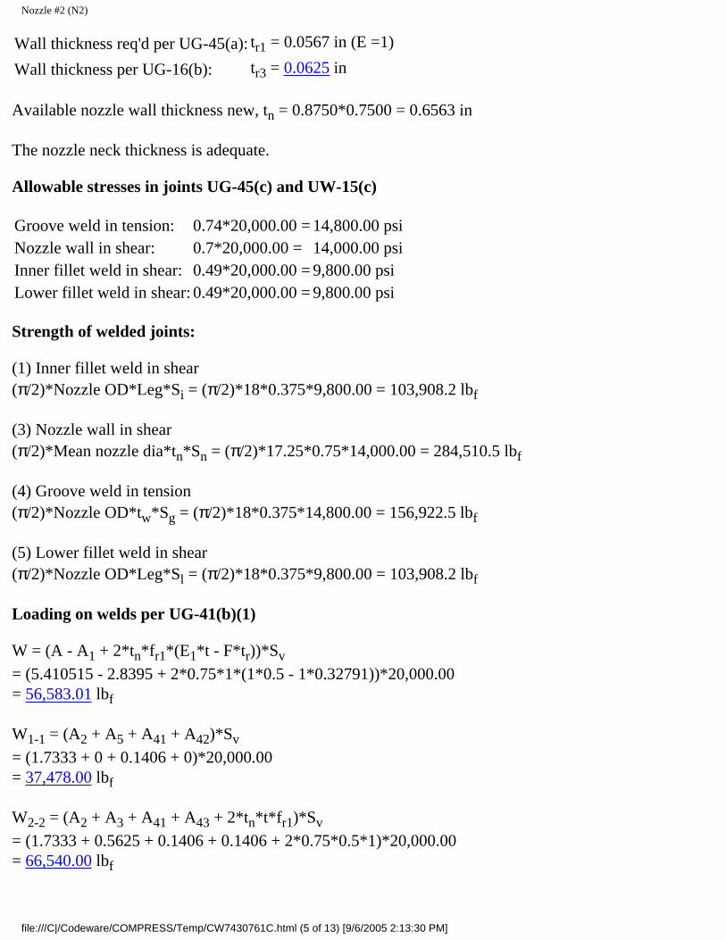
Nozzle #2 (N2)
Wall thickness req'd per UG-45(a): tr1 = 0.0567 in (E =1)
Wall thickness per UG-16(b): tr3 = 0.0625 in
Available nozzle wall thickness new, tn = 0.8750*0.7500 = 0.6563 in
The nozzle neck thickness is adequate.
Allowable stresses in joints UG-45(c) and UW-15(c)
Groove weld in tension: 0.74*20,000.00 = 14,800.00 psiNozzle wall in shear: 0.7*20,000.00 = 14,000.00 psiInner fillet weld in shear: 0.49*20,000.00 = 9,800.00 psiLower fillet weld in shear: 0.49*20,000.00 = 9,800.00 psi
Strength of welded joints:
(1) Inner fillet weld in shear(π/2)*Nozzle OD*Leg*Si = (π/2)*18*0.375*9,800.00 = 103,908.2 lbf
(3) Nozzle wall in shear(π/2)*Mean nozzle dia*tn*Sn = (π/2)*17.25*0.75*14,000.00 = 284,510.5 lbf
(4) Groove weld in tension(π/2)*Nozzle OD*tw*Sg = (π/2)*18*0.375*14,800.00 = 156,922.5 lbf
(5) Lower fillet weld in shear(π/2)*Nozzle OD*Leg*Sl = (π/2)*18*0.375*9,800.00 = 103,908.2 lbf
Loading on welds per UG-41(b)(1)
W = (A - A1 + 2*tn*fr1*(E1*t - F*tr))*Sv
= (5.410515 - 2.8395 + 2*0.75*1*(1*0.5 - 1*0.32791))*20,000.00= 56,583.01 lbf
W1-1 = (A2 + A5 + A41 + A42)*Sv
= (1.7333 + 0 + 0.1406 + 0)*20,000.00= 37,478.00 lbf
W2-2 = (A2 + A3 + A41 + A43 + 2*tn*t*fr1)*Sv
= (1.7333 + 0.5625 + 0.1406 + 0.1406 + 2*0.75*0.5*1)*20,000.00= 66,540.00 lbf
file:///C|/Codeware/COMPRESS/Temp/CW7430761C.html (5 of 13) [9/6/2005 2:13:30 PM]

Nozzle #2 (N2)
Load for path 1-1 lesser of W or W1-1 = 37,478.00 lbf
Path 1-1 through (1) & (3) = 103,908.2 + 284,510.5 = 388,418.7 lbf
Path 1-1 is stronger than W1-1 so it is acceptable per UG-41(b)(1).
Load for path 2-2 lesser of W or W2-2 = 56,583.01 lbf
Path 2-2 through (1), (4), (5) = 103,908.2 + 156,922.5 + 103,908.2 = 364,738.9 lbf
Path 2-2 is stronger than W so it is acceptable per UG-41(b)(2).
Reinforcement Calculations for MAP
Available reinforcement per UG-37 governs the MAP of this nozzle.
UG-37 Area Calculation Summary (in2)For P = 137.05 psi @ 70.00 °FThe opening is adequately reinforced
UG-45 Nozzle WallThickness Summary (in)The nozzle passes UG-45
Arequired
Aavailable
A1 A2 A3 A5Awelds
treq tmin
5.4125 5.4142 2.8375 1.7330 0.5625 -- 0.2812 0.0625 0.6563
Weld Failure Path Analysis Summary (lbf)All failure paths are stronger than the applicable weld loads
Weld loadW
Weld loadW1-1
Path 1-1strength
Weld loadW2-2
Path 2-2strength
56,658.99 37,472.00 388,418.69 66,534.00 364,738.91
UW-16 Weld Sizing Summary
Weld descriptionRequired weldthroat size (in)
Actual weldthroat size (in)
Status
Nozzle to shell fillet (Leg41) 0.2500 0.2625 weld size is adequate
Nozzle to inside shell fillet (Leg43) 0.2500 0.2625(corroded)
weld size is adequate
Nozzle to shell groove (Lower) 0.3625 0.3750 weld size is adequate
Calculations for internal pressure 137.05 psi @ 70.00 °F
file:///C|/Codeware/COMPRESS/Temp/CW7430761C.html (6 of 13) [9/6/2005 2:13:30 PM]

Nozzle #2 (N2)
Limits of reinforcement per UG-40
Parallel to the vessel wall: d = 16.5000 inNormal to the vessel wall outside: 2.5*(t - C) = 1.2500 inNormal to the vessel wall inside: 2.5*(t - C) = 1.2500 in
Nozzle required thickness per UG-27(c)(1)
trn = P*Rn/(Sn*E - 0.6*P)
= 137.0544*8.25/(20,000.00*1 - 0.6*137.0544)= 0.0568 in
Required thickness tr from UG-37(a)
tr = P*Ro/(S*E + 0.4*P)
= 137.0544*48/(20,000.00*1 + 0.4*137.0544)= 0.3280 in
Area required per UG-37(c)
Allowable stresses: Sn = 20,000.00, Sv = 20,000.00 psi
fr1 = lesser of 1 or Sn/Sv = 1
fr2 = lesser of 1 or Sn/Sv = 1
A = d*tr*F + 2*tn*tr*F*(1 - fr1)
= 16.5*0.32803*1 + 2*0.75*0.32803*1*(1 - 1)= 5.4125 in2
Area available from FIG. UG-37.1
A1 = larger of the following= 2.8375 in2
= d*(E1*t - F*tr) - 2*tn*(E1*t - F*tr)*(1 - fr1)
= 16.5*(1*0.5 - 1*0.32803) - 2*0.75*(1*0.5 - 1*0.32803)*(1 - 1)= 2.8375 in2
= 2*(t + tn)*(E1*t - F*tr) - 2*tn*(E1*t - F*tr)*(1 - fr1)
= 2*(0.5 + 0.75)*(1*0.5 - 1*0.32803) - 2*0.75*(1*0.5 - 1*0.32803)*(1 - 1)= 0.4299 in2
A2 = smaller of the following= 1.7330 in2
file:///C|/Codeware/COMPRESS/Temp/CW7430761C.html (7 of 13) [9/6/2005 2:13:30 PM]

Nozzle #2 (N2)
= 5*(tn - trn)*fr2*t
= 5*(0.75 - 0.0568)*1*0.5= 1.7330 in2
= 5*(tn - trn)*fr2*tn= 5*(0.75 - 0.0568)*1*0.75= 2.5995 in2
A3 = smaller of the following= 0.5625 in2
= 5*t*ti*fr2
= 5*0.5*0.75*1= 1.8750 in2
= 5*ti*ti*fr2
= 5*0.75*0.75*1= 2.8125 in2
= 2*h*ti*fr2
= 2*0.375*0.75*1= 0.5625 in2
A41 = Leg2*fr2
= 0.3752*1 =0.1406 in2
A43 = Leg2*fr2
= 0.3752*1 = 0.1406 in2
Area = A1 + A2 + A3 + A41 + A43
= 2.8375 + 1.733 + 0.5625 + 0.1406 + 0.1406= 5.4142 in2
As Area >= A the reinforcement is adequate.
UW-16(d) Weld Check
tmin = lesser of 0.75 or tn or t = 0.5000 in
t1(min) or t2(min) = lesser of 0.25 or 0.7*tmin = 0.2500 in
t1(actual) = 0.7*Leg = 0.7*0.375 = 0.2625 in
The weld size t1 is satisfactory.
file:///C|/Codeware/COMPRESS/Temp/CW7430761C.html (8 of 13) [9/6/2005 2:13:30 PM]

Nozzle #2 (N2)
t2(actual) = 0.375 in
The weld size t2 is satisfactory.
t1 + t2 = 0.6375 >= 1.25*tmin
The combined weld sizes for t1 and t2 are satisfactory.
UG-45 Nozzle Neck Thickness Check (Access Opening)
Wall thickness req'd per UG-45(a): tr1 = 0.0568 in (E =1)
Wall thickness per UG-16(b): tr3 = 0.0625 in
Available nozzle wall thickness new, tn = 0.8750*0.7500 = 0.6563 in
The nozzle neck thickness is adequate.
Allowable stresses in joints UG-45(c) and UW-15(c)
Groove weld in tension: 0.74*20,000.00 = 14,800.00 psiNozzle wall in shear: 0.7*20,000.00 = 14,000.00 psiInner fillet weld in shear: 0.49*20,000.00 = 9,800.00 psiLower fillet weld in shear: 0.49*20,000.00 = 9,800.00 psi
Strength of welded joints:
(1) Inner fillet weld in shear(π/2)*Nozzle OD*Leg*Si = (π/2)*18*0.375*9,800.00 = 103,908.2 lbf
(3) Nozzle wall in shear(π/2)*Mean nozzle dia*tn*Sn = (π/2)*17.25*0.75*14,000.00 = 284,510.5 lbf
(4) Groove weld in tension(π/2)*Nozzle OD*tw*Sg = (π/2)*18*0.375*14,800.00 = 156,922.5 lbf
(5) Lower fillet weld in shear(π/2)*Nozzle OD*Leg*Sl = (π/2)*18*0.375*9,800.00 = 103,908.2 lbf
Loading on welds per UG-41(b)(1)
W = (A - A1 + 2*tn*fr1*(E1*t - F*tr))*Sv
= (5.412495 - 2.8375 + 2*0.75*1*(1*0.5 - 1*0.32803))*20,000.00= 56,658.99 lbf
file:///C|/Codeware/COMPRESS/Temp/CW7430761C.html (9 of 13) [9/6/2005 2:13:30 PM]

Nozzle #2 (N2)
W1-1 = (A2 + A5 + A41 + A42)*Sv
= (1.733 + 0 + 0.1406 + 0)*20,000.00= 37,472.00 lbf
W2-2 = (A2 + A3 + A41 + A43 + 2*tn*t*fr1)*Sv
= (1.733 + 0.5625 + 0.1406 + 0.1406 + 2*0.75*0.5*1)*20,000.00= 66,534.00 lbf
Load for path 1-1 lesser of W or W1-1 = 37,472.00 lbf
Path 1-1 through (1) & (3) = 103,908.2 + 284,510.5 = 388,418.7 lbf
Path 1-1 is stronger than W1-1 so it is acceptable per UG-41(b)(1).
Load for path 2-2 lesser of W or W2-2 = 56,658.99 lbf
Path 2-2 through (1), (4), (5) = 103,908.2 + 156,922.5 + 103,908.2 = 364,738.9 lbf
Path 2-2 is stronger than W so it is acceptable per UG-41(b)(2).
Reinforcement Calculations for External Pressure
UG-37 Area Calculation Summary (in2)For Pe = 31.34 psi @ 300.00 °FThe opening is adequately reinforced
UG-45 Nozzle WallThickness Summary (in)The nozzle passes UG-45
Arequired
Aavailable
A1 A2 A3 A5Awelds
treq tmin
3.6222 3.6223 1.0055 1.7731 0.5625 -- 0.2812 0.0625 0.6563
Weld Failure Path Analysis Summary
Weld strength calculations are not required for external pressure
UW-16 Weld Sizing Summary
Weld descriptionRequired weldthroat size (in)
Actual weldthroat size (in)
Status
Nozzle to shell fillet (Leg41) 0.2500 0.2625 weld size is adequate
Nozzle to inside shell fillet (Leg43) 0.2500 0.2625(corroded)
weld size is adequate
Nozzle to shell groove (Lower) 0.3625 0.3750 weld size is adequate
file:///C|/Codeware/COMPRESS/Temp/CW7430761C.html (10 of 13) [9/6/2005 2:13:30 PM]

Nozzle #2 (N2)
Calculations for external pressure 31.34 psi @ 300.00 °F
Limits of reinforcement per UG-40
Parallel to the vessel wall: d = 16.5000 inNormal to the vessel wall outside: 2.5*(t - C) = 1.2500 inNormal to the vessel wall inside: 2.5*(t - C) = 1.2500 in
Nozzle required thickness per UG-28 trn = 0.0408 in
From UG-37(d)(1) required thickness tr = 0.4391 in
Area required per UG-37(d)(1)
Allowable stresses: Sn = 20,000.00, Sv = 20,000.00 psi
fr1 = lesser of 1 or Sn/Sv = 1
fr2 = lesser of 1 or Sn/Sv = 1
A = 0.5*(d*tr*F + 2*tn*tr*F*(1 - fr1))
= 0.5*(16.5*0.43906*1 + 2*0.75*0.43906*1*(1 - 1))= 3.6222 in2
Area available from FIG. UG-37.1
A1 = larger of the following= 1.0055 in2
= d*(E1*t - F*tr) - 2*tn*(E1*t - F*tr)*(1 - fr1)
= 16.5*(1*0.5 - 1*0.43906) - 2*0.75*(1*0.5 - 1*0.43906)*(1 - 1)= 1.0055 in2
= 2*(t + tn)*(E1*t - F*tr) - 2*tn*(E1*t - F*tr)*(1 - fr1)
= 2*(0.5 + 0.75)*(1*0.5 - 1*0.43906) - 2*0.75*(1*0.5 - 1*0.43906)*(1 - 1)= 0.1523 in2
A2 = smaller of the following= 1.7731 in2
= 5*(tn - trn)*fr2*t
file:///C|/Codeware/COMPRESS/Temp/CW7430761C.html (11 of 13) [9/6/2005 2:13:30 PM]

Nozzle #2 (N2)
= 5*(0.75 - 4.075103E-02)*1*0.5= 1.7731 in2
= 5*(tn - trn)*fr2*tn= 5*(0.75 - 4.075103E-02)*1*0.75= 2.6597 in2
A3 = smaller of the following= 0.5625 in2
= 5*t*ti*fr2
= 5*0.5*0.75*1= 1.8750 in2
= 5*ti*ti*fr2
= 5*0.75*0.75*1= 2.8125 in2
= 2*h*ti*fr2
= 2*0.375*0.75*1= 0.5625 in2
A41 = Leg2*fr2
= 0.3752*1 =0.1406 in2
A43 = Leg2*fr2
= 0.3752*1 = 0.1406 in2
Area = A1 + A2 + A3 + A41 + A43
= 1.0055 + 1.7731 + 0.5625 + 0.1406 + 0.1406= 3.6223 in2
As Area >= A the reinforcement is adequate.
UW-16(d) Weld Check
tmin = lesser of 0.75 or tn or t = 0.5000 in
t1(min) or t2(min) = lesser of 0.25 or 0.7*tmin = 0.2500 in
t1(actual) = 0.7*Leg = 0.7*0.375 = 0.2625 in
The weld size t1 is satisfactory.
t2(actual) = 0.375 in
The weld size t2 is satisfactory.
file:///C|/Codeware/COMPRESS/Temp/CW7430761C.html (12 of 13) [9/6/2005 2:13:30 PM]
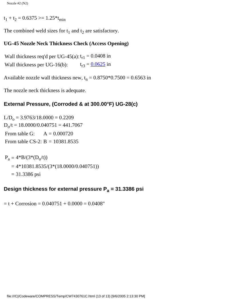
Nozzle #2 (N2)
t1 + t2 = 0.6375 >= 1.25*tmin
The combined weld sizes for t1 and t2 are satisfactory.
UG-45 Nozzle Neck Thickness Check (Access Opening)
Wall thickness req'd per UG-45(a): tr1 = 0.0408 in
Wall thickness per UG-16(b): tr3 = 0.0625 in
Available nozzle wall thickness new, tn = 0.8750*0.7500 = 0.6563 in
The nozzle neck thickness is adequate.
External Pressure, (Corroded & at 300.00°F) UG-28(c)
L/Do = 3.9763/18.0000 = 0.2209
Do/t = 18.0000/0.040751 = 441.7067
From table G: A = 0.000720
From table CS-2: B = 10381.8535
Pa = 4*B/(3*(Do/t))
= 4*10381.8535/(3*(18.0000/0.040751))
= 31.3386 psi
Design thickness for external pressure Pa = 31.3386 psi
= t + Corrosion = 0.040751 + 0.0000 = 0.0408"
file:///C|/Codeware/COMPRESS/Temp/CW7430761C.html (13 of 13) [9/6/2005 2:13:30 PM]

Nozzle #3 (N3)
Nozzle #3 (N3)
ASME Section VIII Division 1, 2001 Edition, A03 Addenda
tw(lower) = 0.2500 in
Leg41 = 0.3750 in
Note: round inside edges per UG-76(c)
Located on: Ellipsoidal Head #2Liquid static head included: 0 psiNozzle material specification: SA-106 B Smls pipe (ASME II-D p. 10, ln. 15)Nozzle longitudinal joint efficiency: 1.00Nozzle description: 4" Sch 80 (XS)Flange description: 4 inch 150# WN A105Bolt Material: SA-193 B7 Bolt <= 2 1/2Flange rated MDMT: -55.00 °F(UCS-66(b)(1)(b))Liquid static head on flange: 0 psiASME B16.5 flange rating MAWP: 230.00 psi @ 300.00°FASME B16.5 flange rating MAP: 285.00 psi @ 70.00°FASME B16.5 flange hydro test: 450.00 psi @ 70.00°FNozzle orientation: 0 °Calculated as hillside: yes (perpendicular)Local vessel minimum thickness: 0.5000 inNozzle center line offset to datum line: 104.8125 inNozzle inside diameter, new: 3.8260 inNozzle nominal wall thickness: 0.3370 inNozzle corrosion allowance: 0.0000 inOpening chord length: 5.4438 inProjection available outside vessel, Lpr: 8.0918 inDistance to head center, R: 53.0000 in
file:///C|/Codeware/COMPRESS/Temp/CW17153024.html (1 of 12) [9/6/2005 2:13:31 PM]

Nozzle #3 (N3)
Reinforcement Calculations for Internal Pressure
Available reinforcement per UG-37 governs the MAWP of this nozzle.
UG-37 Area Calculation Summary (in2)For P = 125.38 psi @ 300.00 °FThe opening is adequately reinforced
UG-45 Nozzle WallThickness Summary (in)The nozzle passes UG-45
Arequired
Aavailable
A1 A2 A3 A5Awelds
treq tmin
1.6581 1.6588 1.0734 0.4652 -- -- 0.1202 0.2074 0.2949
Weld Failure Path Analysis Summary (lbf)All failure paths are stronger than the applicable weld loads
Weld loadW
Weld loadW1-1
Path 1-1strength
Weld loadW2-2
Path 2-2strength
14,008.62 11,708.00 48,588.89 17,470.70 48,364.13
UW-16 Weld Sizing Summary
Weld descriptionRequired weldthroat size (in)
Actual weldthroat size (in)
Status
Nozzle to shell fillet (Leg41) 0.2359 0.2625 weld size is adequate
Nozzle to shell groove (Lower) 0.2359 0.2500 weld size is adequate
Calculations for internal pressure 125.38 psi @ 300.00 °F
Fig UCS-66.2 general note (1) applies.
Nozzle is impact test exempt to -155 °F per UCS-66(b)(3) (coincident ratio = 0.04618).
Nozzle UCS-66 governing thk: 0.2949 inNozzle rated MDMT: -155.00 °F
Limits of reinforcement per UG-40
Parallel to the vessel wall: d = 5.4438 in
file:///C|/Codeware/COMPRESS/Temp/CW17153024.html (2 of 12) [9/6/2005 2:13:31 PM]

Nozzle #3 (N3)
Normal to the vessel wall outside: 2.5*(tn - Cn) + te = 0.8425 in
Nozzle required thickness per UG-27(c)(1)
trn = P*Rn/(Sn*E - 0.6*P)
= 125.3767*1.913/(17,100.00*1 - 0.6*125.3767)= 0.0141 in
Required thickness tr from UG-37(a)(3)
tr = P*Do*K / (2*S*E + 2*P*(K - 0.1))
= 125.3767*96*1 / (2*20000*1 + 2*125.3767*(1 - 0.1)) = 0.2992"
Area required per UG-37(c)
Allowable stresses: Sn = 17,100.00, Sv = 20,000.00 psi
fr1 = lesser of 1 or Sn/Sv = 0.855
fr2 = lesser of 1 or Sn/Sv = 0.855
A = d*tr*F + 2*tn*tr*F*(1 - fr1)
= 5.443769*0.29922*1 + 2*0.337*0.29922*1*(1 - 0.855)= 1.6581 in2
Area available from FIG. UG-37.1
A1 = larger of the following= 1.0734 in2
= d*(E1*t - F*tr) - 2*tn*(E1*t - F*tr)*(1 - fr1)
= 5.443769*(1*0.5 - 1*0.29922) - 2*0.337*(1*0.5 - 1*0.29922)*(1 - 0.855)= 1.0734 in2
= 2*(t + tn)*(E1*t - F*tr) - 2*tn*(E1*t - F*tr)*(1 - fr1)
= 2*(0.5 + 0.337)*(1*0.5 - 1*0.29922) - 2*0.337*(1*0.5 - 1*0.29922)*(1 - 0.855)= 0.3165 in2
A2 = smaller of the following= 0.4652 in2
= 5*(tn - trn)*fr2*t
= 5*(0.337 - 0.0141)*0.855*0.5= 0.6902 in2
file:///C|/Codeware/COMPRESS/Temp/CW17153024.html (3 of 12) [9/6/2005 2:13:31 PM]

Nozzle #3 (N3)
= 5*(tn - trn)*fr2*tn= 5*(0.337 - 0.0141)*0.855*0.337= 0.4652 in2
A41 = Leg2*fr2
= 0.3752*0.855 =0.1202 in2
Area = A1 + A2 + A41
= 1.0734 + 0.4652 + 0.1202= 1.6588 in2
As Area >= A the reinforcement is adequate.
UW-16(d) Weld Check
tmin = lesser of 0.75 or tn or t = 0.3370 in
t1(min) or t2(min) = lesser of 0.25 or 0.7*tmin = 0.2359 in
t1(actual) = 0.7*Leg = 0.7*0.375 = 0.2625 in
The weld size t1 is satisfactory.
t2(actual) = 0.25 in
The weld size t2 is satisfactory.
t1 + t2 = 0.5125 >= 1.25*tmin
The combined weld sizes for t1 and t2 are satisfactory.
UG-45 Nozzle Neck Thickness Check
Interpretation VIII-1-83-66 has been applied.
Wall thickness per UG-45(a): tr1 = 0.0141 in (E =1)
Wall thickness per UG-45(b)(1): tr2 = 0.2992 in
Wall thickness per UG-16(b): tr3 = 0.0625 in
Standard wall pipe per UG-45(b)(4): tr4 = 0.2074 in
The greater of tr2 or tr3: tr5 = 0.2992 in
The lesser of tr4 or tr5: tr6 = 0.2074 in
Required per UG-45 is the larger of tr1 or tr6 = 0.2074 in
Available nozzle wall thickness new, tn = 0.8750*0.3370 = 0.2949 in
file:///C|/Codeware/COMPRESS/Temp/CW17153024.html (4 of 12) [9/6/2005 2:13:31 PM]

Nozzle #3 (N3)
The nozzle neck thickness is adequate.
Allowable stresses in joints UG-45(c) and UW-15(c)
Groove weld in tension: 0.74*20,000.00 = 14,800.00 psiNozzle wall in shear: 0.7*17,100.00 = 11,970.00 psiInner fillet weld in shear: 0.49*17,100.00 = 8,379.00 psi
Strength of welded joints:
(1) Inner fillet weld in shear(π/2)*Nozzle OD*Leg*Si = (π/2)*4.5*0.375*8,379.00 = 22,210.37 lbf
(3) Nozzle wall in shear(π/2)*Mean nozzle dia*tn*Sn = (π/2)*4.163*0.337*11,970.00 = 26,378.52 lbf
(4) Groove weld in tension(π/2)*Nozzle OD*tw*Sg = (π/2)*4.5*0.25*14,800.00 = 26,153.76 lbf
Loading on welds per UG-41(b)(1)
W = (A - A1 + 2*tn*fr1*(E1*t - F*tr))*Sv
= (1.658127 - 1.0734 + 2*0.337*0.855*(1*0.5 - 1*0.29922))*20,000.00= 14,008.62 lbf
W1-1 = (A2 + A5 + A41 + A42)*Sv
= (0.4652 + 0 + 0.1202 + 0)*20,000.00= 11,708.00 lbf
W2-2 = (A2 + A3 + A41 + A43 + 2*tn*t*fr1)*Sv
= (0.4652 + 0 + 0.1202 + 0 + 2*0.337*0.5*0.855)*20,000.00= 17,470.70 lbf
Load for path 1-1 lesser of W or W1-1 = 11,708.00 lbf
Path 1-1 through (1) & (3) = 22,210.37 + 26,378.52 = 48,588.89 lbf
Path 1-1 is stronger than W1-1 so it is acceptable per UG-41(b)(1).
Load for path 2-2 lesser of W or W2-2 = 14,008.62 lbf
Path 2-2 through (1), (4) = 22,210.37 + 26,153.76 = 48,364.13 lbf
Path 2-2 is stronger than W so it is acceptable per UG-41(b)(2).
file:///C|/Codeware/COMPRESS/Temp/CW17153024.html (5 of 12) [9/6/2005 2:13:31 PM]

Nozzle #3 (N3)
Reinforcement Calculations for MAP
Available reinforcement per UG-37 governs the MAP of this nozzle.
UG-37 Area Calculation Summary (in2)For P = 125.38 psi @ 70.00 °FThe opening is adequately reinforced
UG-45 Nozzle WallThickness Summary (in)The nozzle passes UG-45
Arequired
Aavailable
A1 A2 A3 A5Awelds
treq tmin
1.6581 1.6588 1.0734 0.4652 -- -- 0.1202 0.2074 0.2949
Weld Failure Path Analysis Summary (lbf)All failure paths are stronger than the applicable weld loads
Weld loadW
Weld loadW1-1
Path 1-1strength
Weld loadW2-2
Path 2-2strength
14,008.62 11,708.00 48,588.89 17,470.70 48,364.13
UW-16 Weld Sizing Summary
Weld descriptionRequired weldthroat size (in)
Actual weldthroat size (in)
Status
Nozzle to shell fillet (Leg41) 0.2359 0.2625 weld size is adequate
Nozzle to shell groove (Lower) 0.2359 0.2500 weld size is adequate
Calculations for internal pressure 125.38 psi @ 70.00 °F
Limits of reinforcement per UG-40
Parallel to the vessel wall: d = 5.4438 in
Normal to the vessel wall outside: 2.5*(tn - Cn) + te = 0.8425 in
Nozzle required thickness per UG-27(c)(1)
trn = P*Rn/(Sn*E - 0.6*P)
= 125.3767*1.913/(17,100.00*1 - 0.6*125.3767)= 0.0141 in
file:///C|/Codeware/COMPRESS/Temp/CW17153024.html (6 of 12) [9/6/2005 2:13:31 PM]

Nozzle #3 (N3)
Required thickness tr from UG-37(a)(3)
tr = P*Do*K / (2*S*E + 2*P*(K - 0.1))
= 125.3767*96*1 / (2*20000*1 + 2*125.3767*(1 - 0.1)) = 0.2992"
Area required per UG-37(c)
Allowable stresses: Sn = 17,100.00, Sv = 20,000.00 psi
fr1 = lesser of 1 or Sn/Sv = 0.855
fr2 = lesser of 1 or Sn/Sv = 0.855
A = d*tr*F + 2*tn*tr*F*(1 - fr1)
= 5.443769*0.29922*1 + 2*0.337*0.29922*1*(1 - 0.855)= 1.6581 in2
Area available from FIG. UG-37.1
A1 = larger of the following= 1.0734 in2
= d*(E1*t - F*tr) - 2*tn*(E1*t - F*tr)*(1 - fr1)
= 5.443769*(1*0.5 - 1*0.29922) - 2*0.337*(1*0.5 - 1*0.29922)*(1 - 0.855)= 1.0734 in2
= 2*(t + tn)*(E1*t - F*tr) - 2*tn*(E1*t - F*tr)*(1 - fr1)
= 2*(0.5 + 0.337)*(1*0.5 - 1*0.29922) - 2*0.337*(1*0.5 - 1*0.29922)*(1 - 0.855)= 0.3165 in2
A2 = smaller of the following= 0.4652 in2
= 5*(tn - trn)*fr2*t
= 5*(0.337 - 0.0141)*0.855*0.5= 0.6902 in2
= 5*(tn - trn)*fr2*tn= 5*(0.337 - 0.0141)*0.855*0.337= 0.4652 in2
A41 = Leg2*fr2
= 0.3752*0.855 =0.1202 in2
file:///C|/Codeware/COMPRESS/Temp/CW17153024.html (7 of 12) [9/6/2005 2:13:31 PM]

Nozzle #3 (N3)
Area = A1 + A2 + A41
= 1.0734 + 0.4652 + 0.1202= 1.6588 in2
As Area >= A the reinforcement is adequate.
UW-16(d) Weld Check
tmin = lesser of 0.75 or tn or t = 0.3370 in
t1(min) or t2(min) = lesser of 0.25 or 0.7*tmin = 0.2359 in
t1(actual) = 0.7*Leg = 0.7*0.375 = 0.2625 in
The weld size t1 is satisfactory.
t2(actual) = 0.25 in
The weld size t2 is satisfactory.
t1 + t2 = 0.5125 >= 1.25*tmin
The combined weld sizes for t1 and t2 are satisfactory.
UG-45 Nozzle Neck Thickness Check
Interpretation VIII-1-83-66 has been applied.
Wall thickness per UG-45(a): tr1 = 0.0141 in (E =1)
Wall thickness per UG-45(b)(1): tr2 = 0.2992 in
Wall thickness per UG-16(b): tr3 = 0.0625 in
Standard wall pipe per UG-45(b)(4): tr4 = 0.2074 in
The greater of tr2 or tr3: tr5 = 0.2992 in
The lesser of tr4 or tr5: tr6 = 0.2074 in
Required per UG-45 is the larger of tr1 or tr6 = 0.2074 in
Available nozzle wall thickness new, tn = 0.8750*0.3370 = 0.2949 in
The nozzle neck thickness is adequate.
Allowable stresses in joints UG-45(c) and UW-15(c)
Groove weld in tension: 0.74*20,000.00 = 14,800.00 psiNozzle wall in shear: 0.7*17,100.00 = 11,970.00 psi
file:///C|/Codeware/COMPRESS/Temp/CW17153024.html (8 of 12) [9/6/2005 2:13:31 PM]

Nozzle #3 (N3)
Inner fillet weld in shear: 0.49*17,100.00 = 8,379.00 psi
Strength of welded joints:
(1) Inner fillet weld in shear(π/2)*Nozzle OD*Leg*Si = (π/2)*4.5*0.375*8,379.00 = 22,210.37 lbf
(3) Nozzle wall in shear(π/2)*Mean nozzle dia*tn*Sn = (π/2)*4.163*0.337*11,970.00 = 26,378.52 lbf
(4) Groove weld in tension(π/2)*Nozzle OD*tw*Sg = (π/2)*4.5*0.25*14,800.00 = 26,153.76 lbf
Loading on welds per UG-41(b)(1)
W = (A - A1 + 2*tn*fr1*(E1*t - F*tr))*Sv
= (1.658127 - 1.0734 + 2*0.337*0.855*(1*0.5 - 1*0.29922))*20,000.00= 14,008.62 lbf
W1-1 = (A2 + A5 + A41 + A42)*Sv
= (0.4652 + 0 + 0.1202 + 0)*20,000.00= 11,708.00 lbf
W2-2 = (A2 + A3 + A41 + A43 + 2*tn*t*fr1)*Sv
= (0.4652 + 0 + 0.1202 + 0 + 2*0.337*0.5*0.855)*20,000.00= 17,470.70 lbf
Load for path 1-1 lesser of W or W1-1 = 11,708.00 lbf
Path 1-1 through (1) & (3) = 22,210.37 + 26,378.52 = 48,588.89 lbf
Path 1-1 is stronger than W1-1 so it is acceptable per UG-41(b)(1).
Load for path 2-2 lesser of W or W2-2 = 14,008.62 lbf
Path 2-2 through (1), (4) = 22,210.37 + 26,153.76 = 48,364.13 lbf
Path 2-2 is stronger than W so it is acceptable per UG-41(b)(2).
Reinforcement Calculations for External Pressure
UG-37 Area Calculation Summary (in2)For Pe = 39.06 psi @ 300.00 °FThe opening is adequately reinforced
UG-45 Nozzle WallThickness Summary (in)The nozzle passes UG-45
file:///C|/Codeware/COMPRESS/Temp/CW17153024.html (9 of 12) [9/6/2005 2:13:31 PM]

Nozzle #3 (N3)
Arequired
Aavailable
A1 A2 A3 A5Awelds
treq tmin
1.1032 1.1033 0.5445 0.4386 -- -- 0.1202 0.0936 0.2949
Weld Failure Path Analysis Summary
Weld strength calculations are not required for external pressure
UW-16 Weld Sizing Summary
Weld descriptionRequired weldthroat size (in)
Actual weldthroat size (in)
Status
Nozzle to shell fillet (Leg41) 0.2359 0.2625 weld size is adequate
Nozzle to shell groove (Lower) 0.2359 0.2500 weld size is adequate
Calculations for external pressure 39.06 psi @ 300.00 °F
Limits of reinforcement per UG-40
Parallel to the vessel wall: d = 5.4438 in
Normal to the vessel wall outside: 2.5*(tn - Cn) + te = 0.8425 in
Nozzle required thickness per UG-28 trn = 0.0326 in
From UG-37(d)(1) required thickness tr = 0.3982 in
Area required per UG-37(d)(1)
Allowable stresses: Sn = 17,100.00, Sv = 20,000.00 psi
fr1 = lesser of 1 or Sn/Sv = 0.855
fr2 = lesser of 1 or Sn/Sv = 0.855
A = 0.5*(d*tr*F + 2*tn*tr*F*(1 - fr1))
= 0.5*(5.443769*0.39815*1 + 2*0.337*0.39815*1*(1 - 0.855))= 1.1032 in2
file:///C|/Codeware/COMPRESS/Temp/CW17153024.html (10 of 12) [9/6/2005 2:13:31 PM]

Nozzle #3 (N3)
Area available from FIG. UG-37.1
A1 = larger of the following= 0.5445 in2
= d*(E1*t - F*tr) - 2*tn*(E1*t - F*tr)*(1 - fr1)
= 5.443769*(1*0.5 - 1*0.39815) - 2*0.337*(1*0.5 - 1*0.39815)*(1 - 0.855)= 0.5445 in2
= 2*(t + tn)*(E1*t - F*tr) - 2*tn*(E1*t - F*tr)*(1 - fr1)
= 2*(0.5 + 0.337)*(1*0.5 - 1*0.39815) - 2*0.337*(1*0.5 - 1*0.39815)*(1 - 0.855)= 0.1605 in2
A2 = smaller of the following= 0.4386 in2
= 5*(tn - trn)*fr2*t
= 5*(0.337 - 3.255921E-02)*0.855*0.5= 0.6507 in2
= 5*(tn - trn)*fr2*tn= 5*(0.337 - 3.255921E-02)*0.855*0.337= 0.4386 in2
A41 = Leg2*fr2
= 0.3752*0.855 =0.1202 in2
Area = A1 + A2 + A41
= 0.5445 + 0.4386 + 0.1202= 1.1033 in2
As Area >= A the reinforcement is adequate.
UW-16(d) Weld Check
tmin = lesser of 0.75 or tn or t = 0.3370 in
t1(min) or t2(min) = lesser of 0.25 or 0.7*tmin = 0.2359 in
t1(actual) = 0.7*Leg = 0.7*0.375 = 0.2625 in
The weld size t1 is satisfactory.
t2(actual) = 0.25 in
The weld size t2 is satisfactory.
t1 + t2 = 0.5125 >= 1.25*tmin
file:///C|/Codeware/COMPRESS/Temp/CW17153024.html (11 of 12) [9/6/2005 2:13:31 PM]

Nozzle #3 (N3)
The combined weld sizes for t1 and t2 are satisfactory.
UG-45 Nozzle Neck Thickness Check
Interpretation VIII-1-83-66 has been applied.
Wall thickness per UG-45(a): tr1 = 0.0326 in
Wall thickness per UG-45(b)(2): tr2 = 0.0936 in
Wall thickness per UG-16(b): tr3 = 0.0625 in
Standard wall pipe per UG-45(b)(4): tr4 = 0.2074 in
The greater of tr2 or tr3: tr5 = 0.0936 in
The lesser of tr4 or tr5: tr6 = 0.0936 in
Required per UG-45 is the larger of tr1 or tr6 = 0.0936 in
Available nozzle wall thickness new, tn = 0.8750*0.3370 = 0.2949 in
The nozzle neck thickness is adequate.
External Pressure, (Corroded & at 300.00°F) UG-28(c)
L/Do = 12.5589/4.5000 = 2.7909
Do/t = 4.5000/0.032559 = 138.2097
From table G: A = 0.000282
From table CS-2: B = 4049.0488
Pa = 4*B/(3*(Do/t))
= 4*4049.0488/(3*(4.5000/0.032559))
= 39.0619 psi
Design thickness for external pressure Pa = 39.0619 psi
= t + Corrosion = 0.032559 + 0.0000 = 0.0326"
file:///C|/Codeware/COMPRESS/Temp/CW17153024.html (12 of 12) [9/6/2005 2:13:31 PM]

Nozzle #4 (N4)
Nozzle #4 (N4)
ASME Section VIII Division 1, 2001 Edition, A03 Addenda
tw(lower) = 0.2500 in
Leg41 = 0.3750 in
Note: round inside edges per UG-76(c)
Located on: Ellipsoidal Head #1Liquid static head included: 4.1413 psiNozzle material specification: SA-106 B Smls pipe (ASME II-D p. 10, ln. 15)Nozzle longitudinal joint efficiency: 1.00Nozzle description: 4" Sch 80 (XS)Flange description: 4 inch 150# WN A105Bolt Material: SA-193 B7 Bolt <= 2 1/2Flange rated MDMT: -55.00 °F(UCS-66(b)(1)(b))Liquid static head on flange: 4.0722 psiASME B16.5 flange rating MAWP: 230.00 psi @ 300.00°FASME B16.5 flange rating MAP: 285.00 psi @ 70.00°FASME B16.5 flange hydro test: 450.00 psi @ 70.00°FNozzle orientation: 0 °Calculated as hillside: yes (perpendicular)Local vessel minimum thickness: 0.5000 inNozzle center line offset to datum line: -12.8125 inNozzle inside diameter, new: 3.8260 inNozzle nominal wall thickness: 0.3370 inNozzle corrosion allowance: 0.0000 inOpening chord length: 5.4423 inProjection available outside vessel, Lpr: 8.0918 inDistance to head center, R: 53.0000 in
file:///C|/Codeware/COMPRESS/Temp/CW5F8DA287.html (1 of 12) [9/6/2005 2:13:32 PM]

Nozzle #4 (N4)
Reinforcement Calculations for Internal Pressure
Available reinforcement per UG-37 governs the MAWP of this nozzle.
UG-37 Area Calculation Summary (in2)For P = 125.36 psi @ 300.00 °FThe opening is adequately reinforced
UG-45 Nozzle WallThickness Summary (in)The nozzle passes UG-45
Arequired
Aavailable
A1 A2 A3 A5Awelds
treq tmin
1.6574 1.6587 1.0733 0.4652 -- -- 0.1202 0.2074 0.2949
Weld Failure Path Analysis Summary (lbf)All failure paths are stronger than the applicable weld loads
Weld loadW
Weld loadW1-1
Path 1-1strength
Weld loadW2-2
Path 2-2strength
13,996.81 11,708.00 48,588.89 17,470.70 48,364.13
UW-16 Weld Sizing Summary
Weld descriptionRequired weldthroat size (in)
Actual weldthroat size (in)
Status
Nozzle to shell fillet (Leg41) 0.2359 0.2625 weld size is adequate
Nozzle to shell groove (Lower) 0.2359 0.2500 weld size is adequate
Calculations for internal pressure 125.36 psi @ 300.00 °F
Fig UCS-66.2 general note (1) applies.
Nozzle is impact test exempt to -155 °F per UCS-66(b)(3) (coincident ratio = 0.04922).
Nozzle UCS-66 governing thk: 0.2949 inNozzle rated MDMT: -155.00 °F
Limits of reinforcement per UG-40
Parallel to the vessel wall: d = 5.4423 in
file:///C|/Codeware/COMPRESS/Temp/CW5F8DA287.html (2 of 12) [9/6/2005 2:13:32 PM]

Nozzle #4 (N4)
Normal to the vessel wall outside: 2.5*(tn - Cn) + te = 0.8425 in
Nozzle required thickness per UG-27(c)(1)
trn = P*Rn/(Sn*E - 0.6*P)
= 125.3571*1.913/(17,100.00*1 - 0.6*125.3571)= 0.0141 in
Required thickness tr from UG-37(a)(3)
tr = P*Do*K / (2*S*E + 2*P*(K - 0.1))
= 125.3571*96*1 / (2*20000*1 + 2*125.3571*(1 - 0.1)) = 0.2992"
Area required per UG-37(c)
Allowable stresses: Sn = 17,100.00, Sv = 20,000.00 psi
fr1 = lesser of 1 or Sn/Sv = 0.855
fr2 = lesser of 1 or Sn/Sv = 0.855
A = d*tr*F + 2*tn*tr*F*(1 - fr1)
= 5.442292*0.29917*1 + 2*0.337*0.29917*1*(1 - 0.855)= 1.6574 in2
Area available from FIG. UG-37.1
A1 = larger of the following= 1.0733 in2
= d*(E1*t - F*tr) - 2*tn*(E1*t - F*tr)*(1 - fr1)
= 5.442292*(1*0.5 - 1*0.29917) - 2*0.337*(1*0.5 - 1*0.29917)*(1 - 0.855)= 1.0733 in2
= 2*(t + tn)*(E1*t - F*tr) - 2*tn*(E1*t - F*tr)*(1 - fr1)
= 2*(0.5 + 0.337)*(1*0.5 - 1*0.29917) - 2*0.337*(1*0.5 - 1*0.29917)*(1 - 0.855)= 0.3166 in2
A2 = smaller of the following= 0.4652 in2
= 5*(tn - trn)*fr2*t
= 5*(0.337 - 0.0141)*0.855*0.5= 0.6902 in2
file:///C|/Codeware/COMPRESS/Temp/CW5F8DA287.html (3 of 12) [9/6/2005 2:13:32 PM]

Nozzle #4 (N4)
= 5*(tn - trn)*fr2*tn= 5*(0.337 - 0.0141)*0.855*0.337= 0.4652 in2
A41 = Leg2*fr2
= 0.3752*0.855 =0.1202 in2
Area = A1 + A2 + A41
= 1.0733 + 0.4652 + 0.1202= 1.6587 in2
As Area >= A the reinforcement is adequate.
UW-16(d) Weld Check
tmin = lesser of 0.75 or tn or t = 0.3370 in
t1(min) or t2(min) = lesser of 0.25 or 0.7*tmin = 0.2359 in
t1(actual) = 0.7*Leg = 0.7*0.375 = 0.2625 in
The weld size t1 is satisfactory.
t2(actual) = 0.25 in
The weld size t2 is satisfactory.
t1 + t2 = 0.5125 >= 1.25*tmin
The combined weld sizes for t1 and t2 are satisfactory.
UG-45 Nozzle Neck Thickness Check
Interpretation VIII-1-83-66 has been applied.
Wall thickness per UG-45(a): tr1 = 0.0141 in (E =1)
Wall thickness per UG-45(b)(1): tr2 = 0.2992 in
Wall thickness per UG-16(b): tr3 = 0.0625 in
Standard wall pipe per UG-45(b)(4): tr4 = 0.2074 in
The greater of tr2 or tr3: tr5 = 0.2992 in
The lesser of tr4 or tr5: tr6 = 0.2074 in
Required per UG-45 is the larger of tr1 or tr6 = 0.2074 in
Available nozzle wall thickness new, tn = 0.8750*0.3370 = 0.2949 in
file:///C|/Codeware/COMPRESS/Temp/CW5F8DA287.html (4 of 12) [9/6/2005 2:13:32 PM]

Nozzle #4 (N4)
The nozzle neck thickness is adequate.
Allowable stresses in joints UG-45(c) and UW-15(c)
Groove weld in tension: 0.74*20,000.00 = 14,800.00 psiNozzle wall in shear: 0.7*17,100.00 = 11,970.00 psiInner fillet weld in shear: 0.49*17,100.00 = 8,379.00 psi
Strength of welded joints:
(1) Inner fillet weld in shear(π/2)*Nozzle OD*Leg*Si = (π/2)*4.5*0.375*8,379.00 = 22,210.37 lbf
(3) Nozzle wall in shear(π/2)*Mean nozzle dia*tn*Sn = (π/2)*4.163*0.337*11,970.00 = 26,378.52 lbf
(4) Groove weld in tension(π/2)*Nozzle OD*tw*Sg = (π/2)*4.5*0.25*14,800.00 = 26,153.76 lbf
Loading on welds per UG-41(b)(1)
W = (A - A1 + 2*tn*fr1*(E1*t - F*tr))*Sv
= (1.657408 - 1.0733 + 2*0.337*0.855*(1*0.5 - 1*0.29917))*20,000.00= 13,996.81 lbf
W1-1 = (A2 + A5 + A41 + A42)*Sv
= (0.4652 + 0 + 0.1202 + 0)*20,000.00= 11,708.00 lbf
W2-2 = (A2 + A3 + A41 + A43 + 2*tn*t*fr1)*Sv
= (0.4652 + 0 + 0.1202 + 0 + 2*0.337*0.5*0.855)*20,000.00= 17,470.70 lbf
Load for path 1-1 lesser of W or W1-1 = 11,708.00 lbf
Path 1-1 through (1) & (3) = 22,210.37 + 26,378.52 = 48,588.89 lbf
Path 1-1 is stronger than W1-1 so it is acceptable per UG-41(b)(1).
Load for path 2-2 lesser of W or W2-2 = 13,996.81 lbf
Path 2-2 through (1), (4) = 22,210.37 + 26,153.76 = 48,364.13 lbf
Path 2-2 is stronger than W so it is acceptable per UG-41(b)(2).
file:///C|/Codeware/COMPRESS/Temp/CW5F8DA287.html (5 of 12) [9/6/2005 2:13:32 PM]

Nozzle #4 (N4)
Reinforcement Calculations for MAP
Available reinforcement per UG-37 governs the MAP of this nozzle.
UG-37 Area Calculation Summary (in2)For P = 125.38 psi @ 70.00 °FThe opening is adequately reinforced
UG-45 Nozzle WallThickness Summary (in)The nozzle passes UG-45
Arequired
Aavailable
A1 A2 A3 A5Awelds
treq tmin
1.6577 1.6585 1.0731 0.4652 -- -- 0.1202 0.2074 0.2949
Weld Failure Path Analysis Summary (lbf)All failure paths are stronger than the applicable weld loads
Weld loadW
Weld loadW1-1
Path 1-1strength
Weld loadW2-2
Path 2-2strength
14,005.78 11,708.00 48,588.89 17,470.70 48,364.13
UW-16 Weld Sizing Summary
Weld descriptionRequired weldthroat size (in)
Actual weldthroat size (in)
Status
Nozzle to shell fillet (Leg41) 0.2359 0.2625 weld size is adequate
Nozzle to shell groove (Lower) 0.2359 0.2500 weld size is adequate
Calculations for internal pressure 125.38 psi @ 70.00 °F
Limits of reinforcement per UG-40
Parallel to the vessel wall: d = 5.4423 in
Normal to the vessel wall outside: 2.5*(tn - Cn) + te = 0.8425 in
Nozzle required thickness per UG-27(c)(1)
trn = P*Rn/(Sn*E - 0.6*P)
= 125.3767*1.913/(17,100.00*1 - 0.6*125.3767)= 0.0141 in
file:///C|/Codeware/COMPRESS/Temp/CW5F8DA287.html (6 of 12) [9/6/2005 2:13:32 PM]

Nozzle #4 (N4)
Required thickness tr from UG-37(a)(3)
tr = P*Do*K / (2*S*E + 2*P*(K - 0.1))
= 125.3767*96*1 / (2*20000*1 + 2*125.3767*(1 - 0.1)) = 0.2992"
Area required per UG-37(c)
Allowable stresses: Sn = 17,100.00, Sv = 20,000.00 psi
fr1 = lesser of 1 or Sn/Sv = 0.855
fr2 = lesser of 1 or Sn/Sv = 0.855
A = d*tr*F + 2*tn*tr*F*(1 - fr1)
= 5.442292*0.29922*1 + 2*0.337*0.29922*1*(1 - 0.855)= 1.6577 in2
Area available from FIG. UG-37.1
A1 = larger of the following= 1.0731 in2
= d*(E1*t - F*tr) - 2*tn*(E1*t - F*tr)*(1 - fr1)
= 5.442292*(1*0.5 - 1*0.29922) - 2*0.337*(1*0.5 - 1*0.29922)*(1 - 0.855)= 1.0731 in2
= 2*(t + tn)*(E1*t - F*tr) - 2*tn*(E1*t - F*tr)*(1 - fr1)
= 2*(0.5 + 0.337)*(1*0.5 - 1*0.29922) - 2*0.337*(1*0.5 - 1*0.29922)*(1 - 0.855)= 0.3165 in2
A2 = smaller of the following= 0.4652 in2
= 5*(tn - trn)*fr2*t
= 5*(0.337 - 0.0141)*0.855*0.5= 0.6902 in2
= 5*(tn - trn)*fr2*tn= 5*(0.337 - 0.0141)*0.855*0.337= 0.4652 in2
A41 = Leg2*fr2
= 0.3752*0.855 =0.1202 in2
file:///C|/Codeware/COMPRESS/Temp/CW5F8DA287.html (7 of 12) [9/6/2005 2:13:32 PM]

Nozzle #4 (N4)
Area = A1 + A2 + A41
= 1.0731 + 0.4652 + 0.1202= 1.6585 in2
As Area >= A the reinforcement is adequate.
UW-16(d) Weld Check
tmin = lesser of 0.75 or tn or t = 0.3370 in
t1(min) or t2(min) = lesser of 0.25 or 0.7*tmin = 0.2359 in
t1(actual) = 0.7*Leg = 0.7*0.375 = 0.2625 in
The weld size t1 is satisfactory.
t2(actual) = 0.25 in
The weld size t2 is satisfactory.
t1 + t2 = 0.5125 >= 1.25*tmin
The combined weld sizes for t1 and t2 are satisfactory.
UG-45 Nozzle Neck Thickness Check
Interpretation VIII-1-83-66 has been applied.
Wall thickness per UG-45(a): tr1 = 0.0141 in (E =1)
Wall thickness per UG-45(b)(1): tr2 = 0.2992 in
Wall thickness per UG-16(b): tr3 = 0.0625 in
Standard wall pipe per UG-45(b)(4): tr4 = 0.2074 in
The greater of tr2 or tr3: tr5 = 0.2992 in
The lesser of tr4 or tr5: tr6 = 0.2074 in
Required per UG-45 is the larger of tr1 or tr6 = 0.2074 in
Available nozzle wall thickness new, tn = 0.8750*0.3370 = 0.2949 in
The nozzle neck thickness is adequate.
Allowable stresses in joints UG-45(c) and UW-15(c)
Groove weld in tension: 0.74*20,000.00 = 14,800.00 psiNozzle wall in shear: 0.7*17,100.00 = 11,970.00 psi
file:///C|/Codeware/COMPRESS/Temp/CW5F8DA287.html (8 of 12) [9/6/2005 2:13:32 PM]

Nozzle #4 (N4)
Inner fillet weld in shear: 0.49*17,100.00 = 8,379.00 psi
Strength of welded joints:
(1) Inner fillet weld in shear(π/2)*Nozzle OD*Leg*Si = (π/2)*4.5*0.375*8,379.00 = 22,210.37 lbf
(3) Nozzle wall in shear(π/2)*Mean nozzle dia*tn*Sn = (π/2)*4.163*0.337*11,970.00 = 26,378.52 lbf
(4) Groove weld in tension(π/2)*Nozzle OD*tw*Sg = (π/2)*4.5*0.25*14,800.00 = 26,153.76 lbf
Loading on welds per UG-41(b)(1)
W = (A - A1 + 2*tn*fr1*(E1*t - F*tr))*Sv
= (1.657685 - 1.0731 + 2*0.337*0.855*(1*0.5 - 1*0.29922))*20,000.00= 14,005.78 lbf
W1-1 = (A2 + A5 + A41 + A42)*Sv
= (0.4652 + 0 + 0.1202 + 0)*20,000.00= 11,708.00 lbf
W2-2 = (A2 + A3 + A41 + A43 + 2*tn*t*fr1)*Sv
= (0.4652 + 0 + 0.1202 + 0 + 2*0.337*0.5*0.855)*20,000.00= 17,470.70 lbf
Load for path 1-1 lesser of W or W1-1 = 11,708.00 lbf
Path 1-1 through (1) & (3) = 22,210.37 + 26,378.52 = 48,588.89 lbf
Path 1-1 is stronger than W1-1 so it is acceptable per UG-41(b)(1).
Load for path 2-2 lesser of W or W2-2 = 14,005.78 lbf
Path 2-2 through (1), (4) = 22,210.37 + 26,153.76 = 48,364.13 lbf
Path 2-2 is stronger than W so it is acceptable per UG-41(b)(2).
Reinforcement Calculations for External Pressure
UG-37 Area Calculation Summary (in2)For Pe = 39.07 psi @ 300.00 °FThe opening is adequately reinforced
UG-45 Nozzle WallThickness Summary (in)The nozzle passes UG-45
file:///C|/Codeware/COMPRESS/Temp/CW5F8DA287.html (9 of 12) [9/6/2005 2:13:32 PM]

Nozzle #4 (N4)
Arequired
Aavailable
A1 A2 A3 A5Awelds
treq tmin
1.1030 1.1030 0.5442 0.4386 -- -- 0.1202 0.0936 0.2949
Weld Failure Path Analysis Summary
Weld strength calculations are not required for external pressure
UW-16 Weld Sizing Summary
Weld descriptionRequired weldthroat size (in)
Actual weldthroat size (in)
Status
Nozzle to shell fillet (Leg41) 0.2359 0.2625 weld size is adequate
Nozzle to shell groove (Lower) 0.2359 0.2500 weld size is adequate
Calculations for external pressure 39.07 psi @ 300.00 °F
Limits of reinforcement per UG-40
Parallel to the vessel wall: d = 5.4423 in
Normal to the vessel wall outside: 2.5*(tn - Cn) + te = 0.8425 in
Nozzle required thickness per UG-28 trn = 0.0326 in
From UG-37(d)(1) required thickness tr = 0.3982 in
Area required per UG-37(d)(1)
Allowable stresses: Sn = 17,100.00, Sv = 20,000.00 psi
fr1 = lesser of 1 or Sn/Sv = 0.855
fr2 = lesser of 1 or Sn/Sv = 0.855
A = 0.5*(d*tr*F + 2*tn*tr*F*(1 - fr1))
= 0.5*(5.442292*0.39818*1 + 2*0.337*0.39818*1*(1 - 0.855))= 1.1030 in2
file:///C|/Codeware/COMPRESS/Temp/CW5F8DA287.html (10 of 12) [9/6/2005 2:13:32 PM]

Nozzle #4 (N4)
Area available from FIG. UG-37.1
A1 = larger of the following= 0.5442 in2
= d*(E1*t - F*tr) - 2*tn*(E1*t - F*tr)*(1 - fr1)
= 5.442292*(1*0.5 - 1*0.39818) - 2*0.337*(1*0.5 - 1*0.39818)*(1 - 0.855)= 0.5442 in2
= 2*(t + tn)*(E1*t - F*tr) - 2*tn*(E1*t - F*tr)*(1 - fr1)
= 2*(0.5 + 0.337)*(1*0.5 - 1*0.39818) - 2*0.337*(1*0.5 - 1*0.39818)*(1 - 0.855)= 0.1605 in2
A2 = smaller of the following= 0.4386 in2
= 5*(tn - trn)*fr2*t
= 5*(0.337 - 3.256109E-02)*0.855*0.5= 0.6507 in2
= 5*(tn - trn)*fr2*tn= 5*(0.337 - 3.256109E-02)*0.855*0.337= 0.4386 in2
A41 = Leg2*fr2
= 0.3752*0.855 =0.1202 in2
Area = A1 + A2 + A41
= 0.5442 + 0.4386 + 0.1202= 1.1030 in2
As Area >= A the reinforcement is adequate.
UW-16(d) Weld Check
tmin = lesser of 0.75 or tn or t = 0.3370 in
t1(min) or t2(min) = lesser of 0.25 or 0.7*tmin = 0.2359 in
t1(actual) = 0.7*Leg = 0.7*0.375 = 0.2625 in
The weld size t1 is satisfactory.
t2(actual) = 0.25 in
The weld size t2 is satisfactory.
t1 + t2 = 0.5125 >= 1.25*tmin
file:///C|/Codeware/COMPRESS/Temp/CW5F8DA287.html (11 of 12) [9/6/2005 2:13:32 PM]

Nozzle #4 (N4)
The combined weld sizes for t1 and t2 are satisfactory.
UG-45 Nozzle Neck Thickness Check
Interpretation VIII-1-83-66 has been applied.
Wall thickness per UG-45(a): tr1 = 0.0326 in
Wall thickness per UG-45(b)(2): tr2 = 0.0936 in
Wall thickness per UG-16(b): tr3 = 0.0625 in
Standard wall pipe per UG-45(b)(4): tr4 = 0.2074 in
The greater of tr2 or tr3: tr5 = 0.0936 in
The lesser of tr4 or tr5: tr6 = 0.0936 in
Required per UG-45 is the larger of tr1 or tr6 = 0.0936 in
Available nozzle wall thickness new, tn = 0.8750*0.3370 = 0.2949 in
The nozzle neck thickness is adequate.
External Pressure, (Corroded & at 300.00°F) UG-28(c)
L/Do = 12.5589/4.5000 = 2.7909
Do/t = 4.5000/0.032561 = 138.2018
From table G: A = 0.000282
From table CS-2: B = 4049.4028
Pa = 4*B/(3*(Do/t))
= 4*4049.4028/(3*(4.5000/0.032561))
= 39.0676 psi
Design thickness for external pressure Pa = 39.0676 psi
= t + Corrosion = 0.032561 + 0.0000 = 0.0326"
file:///C|/Codeware/COMPRESS/Temp/CW5F8DA287.html (12 of 12) [9/6/2005 2:13:32 PM]

Nozzle #5 (N5)
Nozzle #5 (N5)
ASME Section VIII Division 1, 2001 Edition, A03 Addenda
tw(lower) = 0.1870 in
Leg41 = 0.2500 in
Note: round inside edges per UG-76(c)
Located on: Cylinder #1Liquid static head included: 0.4569 psiNozzle material specification: SA-105 (ASME II-D p. 14, ln. 18)Nozzle longitudinal joint efficiency: 1.00Nozzle description: 1" 3000# - threadedNozzle orientation: 90 °Local vessel minimum thickness: 0.5000 inNozzle center line offset to datum line: 88.0000 inEnd of nozzle to shell center: 52.0000 inNozzle inside diameter, new: 1.3150 inNozzle nominal wall thickness: 0.2175 inNozzle corrosion allowance: 0.0000 inProjection available outside vessel, Lpr: 4.0000 in
Reinforcement Calculations for Internal Pressure
The vessel wall thickness governs the MAWP of this nozzle.
UG-37 Area Calculation Summary (in2)For P = 209.16 psi @ 300.00 °F
UG-45 Nozzle WallThickness Summary (in)The nozzle passes UG-45
file:///C|/Codeware/COMPRESS/Temp/CW7DCF34CC.html (1 of 8) [9/6/2005 2:13:32 PM]

Nozzle #5 (N5)
Arequired
Aavailable
A1 A2 A3 A5Awelds
treq tmin
This nozzle is exempt from area calculations per UG-36(c)(3)(a) 0.0625 0.2175
Weld Failure Path Analysis Summary
The nozzle is exempt from weld strength calculations per UW-15(b)(2)
UW-16 Weld Sizing Summary
Weld descriptionRequired weldthroat size (in)
Actual weldthroat size (in)
Status
Nozzle to shell fillet (Leg41) 0.1523 0.1750 weld size is adequate
Nozzle to shell groove (Lower) 0.1523 0.1870 weld size is adequate
Calculations for internal pressure 209.16 psi @ 300.00 °F
Nozzle is impact test exempt to -155 °F per UCS-66(b)(3) (coincident ratio = 0.01846).
Nozzle UCS-66 governing thk: 0.2175 inNozzle rated MDMT: -155.00 °F
Limits of reinforcement per UG-40
Parallel to the vessel wall: (Rn + tn + t )= 1.3750 in
Normal to the vessel wall outside: 2.5*(tn - Cn) + te = 0.5438 in
Nozzle required thickness per UG-27(c)(1)
trn = P*Rn/(Sn*E - 0.6*P)
= 209.1599*0.6575/(20,000.00*1 - 0.6*209.1599)= 0.0069 in
Required thickness tr from UG-37(a)
tr = P*Ro/(S*E + 0.4*P)
= 209.1599*48/(20,000.00*1 + 0.4*209.1599)= 0.4999 in
file:///C|/Codeware/COMPRESS/Temp/CW7DCF34CC.html (2 of 8) [9/6/2005 2:13:32 PM]

Nozzle #5 (N5)
This opening does not require reinforcement per UG-36(c)(3)(a)
Area calculations for weld failure path analysis
Allowable stresses: Sn = 20,000.00, Sv = 20,000.00 psi
fr1 = lesser of 1 or Sn/Sv = 1
fr2 = lesser of 1 or Sn/Sv = 1
A = d*tr*F + 2*tn*tr*F*(1 - fr1)
= 1.315*0.49989*1 + 2*0.2175*0.49989*1*(1 - 1)= 0.6574 in2
A1 = larger of the following= 0.0002 in2
= d*(E1*t - F*tr) - 2*tn*(E1*t - F*tr)*(1 - fr1)
= 1.315*(1*0.5 - 1*0.49989) - 2*0.2175*(1*0.5 - 1*0.49989)*(1 - 1)= 0.0001 in2
= 2*(t + tn)*(E1*t - F*tr) - 2*tn*(E1*t - F*tr)*(1 - fr1)
= 2*(0.5 + 0.2175)*(1*0.5 - 1*0.49989) - 2*0.2175*(1*0.5 - 1*0.49989)*(1 - 1)= 0.0002 in2
A2 = smaller of the following= 0.2290 in2
= 5*(tn - trn)*fr2*t
= 5*(0.2175 - 0.0069)*1*0.5= 0.5265 in2
= 5*(tn - trn)*fr2*tn= 5*(0.2175 - 0.0069)*1*0.2175= 0.2290 in2
A41 = Leg2*fr2
= 0.252*1 =0.0625 in2
UW-16(d) Weld Check
tmin = lesser of 0.75 or tn or t = 0.2175 in
t1(min) or t2(min) = lesser of 0.25 or 0.7*tmin = 0.1522 in
file:///C|/Codeware/COMPRESS/Temp/CW7DCF34CC.html (3 of 8) [9/6/2005 2:13:32 PM]

Nozzle #5 (N5)
t1(actual) = 0.7*Leg = 0.7*0.25 = 0.175 in
The weld size t1 is satisfactory.
t2(actual) = 0.187 in
The weld size t2 is satisfactory.
t1 + t2 = 0.362 >= 1.25*tmin
The combined weld sizes for t1 and t2 are satisfactory.
ASME B16.11 Coupling Wall Thickness Check
Wall thickness req'd per ASME B16.11 2.1.1: tr1 = 0.0091 in (E =1)
Wall thickness per UG-16(b): tr3 = 0.0625 in
Available nozzle wall thickness new, tn = 0.2175 in
The nozzle neck thickness is adequate.
Reinforcement Calculations for MAP
The vessel wall thickness governs the MAP of this nozzle.
UG-37 Area Calculation Summary (in2)For P = 209.16 psi @ 70.00 °F
UG-45 Nozzle WallThickness Summary (in)The nozzle passes UG-45
Arequired
Aavailable
A1 A2 A3 A5Awelds
treq tmin
This nozzle is exempt from area calculations per UG-36(c)(3)(a) 0.0625 0.2175
Weld Failure Path Analysis Summary
The nozzle is exempt from weld strength calculations per UW-15(b)(2)
UW-16 Weld Sizing Summary
Weld descriptionRequired weldthroat size (in)
Actual weldthroat size (in)
Status
Nozzle to shell fillet (Leg41) 0.1523 0.1750 weld size is adequate
Nozzle to shell groove (Lower) 0.1523 0.1870 weld size is adequate
file:///C|/Codeware/COMPRESS/Temp/CW7DCF34CC.html (4 of 8) [9/6/2005 2:13:32 PM]

Nozzle #5 (N5)
Calculations for internal pressure 209.16 psi @ 70.00 °F
Limits of reinforcement per UG-40
Parallel to the vessel wall: (Rn + tn + t )= 1.3750 in
Normal to the vessel wall outside: 2.5*(tn - Cn) + te = 0.5438 in
Nozzle required thickness per UG-27(c)(1)
trn = P*Rn/(Sn*E - 0.6*P)
= 209.1551*0.6575/(20,000.00*1 - 0.6*209.1551)= 0.0069 in
Required thickness tr from UG-37(a)
tr = P*Ro/(S*E + 0.4*P)
= 209.1551*48/(20,000.00*1 + 0.4*209.1551)= 0.4999 in
This opening does not require reinforcement per UG-36(c)(3)(a)
Area calculations for weld failure path analysis
Allowable stresses: Sn = 20,000.00, Sv = 20,000.00 psi
fr1 = lesser of 1 or Sn/Sv = 1
fr2 = lesser of 1 or Sn/Sv = 1
A = d*tr*F + 2*tn*tr*F*(1 - fr1)
= 1.315*0.49988*1 + 2*0.2175*0.49988*1*(1 - 1)= 0.6573 in2
A1 = larger of the following= 0.0002 in2
= d*(E1*t - F*tr) - 2*tn*(E1*t - F*tr)*(1 - fr1)
= 1.315*(1*0.5 - 1*0.49988) - 2*0.2175*(1*0.5 - 1*0.49988)*(1 - 1)= 0.0002 in2
file:///C|/Codeware/COMPRESS/Temp/CW7DCF34CC.html (5 of 8) [9/6/2005 2:13:32 PM]

Nozzle #5 (N5)
= 2*(t + tn)*(E1*t - F*tr) - 2*tn*(E1*t - F*tr)*(1 - fr1)
= 2*(0.5 + 0.2175)*(1*0.5 - 1*0.49988) - 2*0.2175*(1*0.5 - 1*0.49988)*(1 - 1)= 0.0002 in2
A2 = smaller of the following= 0.2290 in2
= 5*(tn - trn)*fr2*t
= 5*(0.2175 - 0.0069)*1*0.5= 0.5265 in2
= 5*(tn - trn)*fr2*tn= 5*(0.2175 - 0.0069)*1*0.2175= 0.2290 in2
A41 = Leg2*fr2
= 0.252*1 =0.0625 in2
UW-16(d) Weld Check
tmin = lesser of 0.75 or tn or t = 0.2175 in
t1(min) or t2(min) = lesser of 0.25 or 0.7*tmin = 0.1522 in
t1(actual) = 0.7*Leg = 0.7*0.25 = 0.175 in
The weld size t1 is satisfactory.
t2(actual) = 0.187 in
The weld size t2 is satisfactory.
t1 + t2 = 0.362 >= 1.25*tmin
The combined weld sizes for t1 and t2 are satisfactory.
ASME B16.11 Coupling Wall Thickness Check
Wall thickness req'd per ASME B16.11 2.1.1: tr1 = 0.0091 in (E =1)
Wall thickness per UG-16(b): tr3 = 0.0625 in
Available nozzle wall thickness new, tn = 0.2175 in
The nozzle neck thickness is adequate.
Reinforcement Calculations for External Pressure
file:///C|/Codeware/COMPRESS/Temp/CW7DCF34CC.html (6 of 8) [9/6/2005 2:13:32 PM]

Nozzle #5 (N5)
UG-37 Area Calculation Summary (in2)For Pe = 43.45 psi @ 300.00 °F
UG-45 Nozzle WallThickness Summary (in)The nozzle passes UG-45
Arequired
Aavailable
A1 A2 A3 A5Awelds
treq tmin
This nozzle is exempt from area calculations per UG-36(c)(3)(a) 0.1042 0.2175
Weld Failure Path Analysis Summary
Weld strength calculations are not required for external pressure
UW-16 Weld Sizing Summary
Weld descriptionRequired weldthroat size (in)
Actual weldthroat size (in)
Status
Nozzle to shell fillet (Leg41) 0.1523 0.1750 weld size is adequate
Nozzle to shell groove (Lower) 0.1523 0.1870 weld size is adequate
Calculations for external pressure 43.45 psi @ 300.00 °F
Limits of reinforcement per UG-40
Parallel to the vessel wall: (Rn + tn + t )= 1.3750 in
Normal to the vessel wall outside: 2.5*(tn - Cn) + te = 0.5438 in
Nozzle required thickness per UG-28 trn = 0.0122 in
From UG-37(d)(1) required thickness tr = 0.5000 in
This opening does not require reinforcement per UG-36(c)(3)(a)
UW-16(d) Weld Check
tmin = lesser of 0.75 or tn or t = 0.2175 in
t1(min) or t2(min) = lesser of 0.25 or 0.7*tmin = 0.1522 in
file:///C|/Codeware/COMPRESS/Temp/CW7DCF34CC.html (7 of 8) [9/6/2005 2:13:32 PM]

Nozzle #5 (N5)
t1(actual) = 0.7*Leg = 0.7*0.25 = 0.175 in
The weld size t1 is satisfactory.
t2(actual) = 0.187 in
The weld size t2 is satisfactory.
t1 + t2 = 0.362 >= 1.25*tmin
The combined weld sizes for t1 and t2 are satisfactory.
UG-45 Nozzle Neck Thickness Check
Wall thickness per UG-45(a): tr1 = 0.0122 in
Wall thickness per UG-45(b)(2): tr2 = 0.1042 in
Wall thickness per UG-16(b): tr3 = 0.0625 in
Standard wall pipe per UG-45(b)(4): tr4 = 0.1269 in
The greater of tr2 or tr3: tr5 = 0.1042 in
The lesser of tr4 or tr5: tr6 = 0.1042 in
Required per UG-45 is the larger of tr1 or tr6 = 0.1042 in
Available nozzle wall thickness new, tn = 0.2175 in
The nozzle neck thickness is adequate.
External Pressure, (Corroded & at 300.00°F) UG-28(c)
L/Do = 4.0080/1.7500 = 2.2903
Do/t = 1.7500/0.012167 = 143.8263
From table G: A = 0.000326
From table CS-2: B = 4687.1914
Pa = 4*B/(3*(Do/t))
= 4*4687.1914/(3*(1.7500/0.012167))
= 43.4523 psi
Design thickness for external pressure Pa = 43.4523 psi
= t + Corrosion = 0.012167 + 0.0000 = 0.0122"
file:///C|/Codeware/COMPRESS/Temp/CW7DCF34CC.html (8 of 8) [9/6/2005 2:13:32 PM]
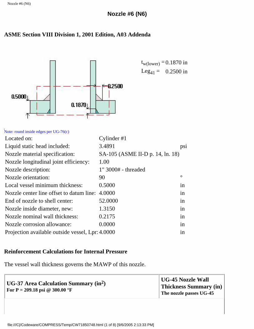
Nozzle #6 (N6)
Nozzle #6 (N6)
ASME Section VIII Division 1, 2001 Edition, A03 Addenda
tw(lower) = 0.1870 in
Leg41 = 0.2500 in
Note: round inside edges per UG-76(c)
Located on: Cylinder #1Liquid static head included: 3.4891 psiNozzle material specification: SA-105 (ASME II-D p. 14, ln. 18)Nozzle longitudinal joint efficiency: 1.00Nozzle description: 1" 3000# - threadedNozzle orientation: 90 °Local vessel minimum thickness: 0.5000 inNozzle center line offset to datum line: 4.0000 inEnd of nozzle to shell center: 52.0000 inNozzle inside diameter, new: 1.3150 inNozzle nominal wall thickness: 0.2175 inNozzle corrosion allowance: 0.0000 inProjection available outside vessel, Lpr: 4.0000 in
Reinforcement Calculations for Internal Pressure
The vessel wall thickness governs the MAWP of this nozzle.
UG-37 Area Calculation Summary (in2)For P = 209.18 psi @ 300.00 °F
UG-45 Nozzle WallThickness Summary (in)The nozzle passes UG-45
file:///C|/Codeware/COMPRESS/Temp/CW71850748.html (1 of 8) [9/6/2005 2:13:33 PM]

Nozzle #6 (N6)
Arequired
Aavailable
A1 A2 A3 A5Awelds
treq tmin
This nozzle is exempt from area calculations per UG-36(c)(3)(a) 0.0625 0.2175
Weld Failure Path Analysis Summary
The nozzle is exempt from weld strength calculations per UW-15(b)(2)
UW-16 Weld Sizing Summary
Weld descriptionRequired weldthroat size (in)
Actual weldthroat size (in)
Status
Nozzle to shell fillet (Leg41) 0.1523 0.1750 weld size is adequate
Nozzle to shell groove (Lower) 0.1523 0.1870 weld size is adequate
Calculations for internal pressure 209.18 psi @ 300.00 °F
Nozzle is impact test exempt to -155 °F per UCS-66(b)(3) (coincident ratio = 0.01892).
Nozzle UCS-66 governing thk: 0.2175 inNozzle rated MDMT: -155.00 °F
Limits of reinforcement per UG-40
Parallel to the vessel wall: (Rn + tn + t )= 1.3750 in
Normal to the vessel wall outside: 2.5*(tn - Cn) + te = 0.5438 in
Nozzle required thickness per UG-27(c)(1)
trn = P*Rn/(Sn*E - 0.6*P)
= 209.1785*0.6575/(20,000.00*1 - 0.6*209.1785)= 0.0069 in
Required thickness tr from UG-37(a)
tr = P*Ro/(S*E + 0.4*P)
= 209.1785*48/(20,000.00*1 + 0.4*209.1785)= 0.4999 in
file:///C|/Codeware/COMPRESS/Temp/CW71850748.html (2 of 8) [9/6/2005 2:13:33 PM]

Nozzle #6 (N6)
This opening does not require reinforcement per UG-36(c)(3)(a)
Area calculations for weld failure path analysis
Allowable stresses: Sn = 20,000.00, Sv = 20,000.00 psi
fr1 = lesser of 1 or Sn/Sv = 1
fr2 = lesser of 1 or Sn/Sv = 1
A = d*tr*F + 2*tn*tr*F*(1 - fr1)
= 1.315*0.49994*1 + 2*0.2175*0.49994*1*(1 - 1)= 0.6574 in2
A1 = larger of the following= 0.0001 in2
= d*(E1*t - F*tr) - 2*tn*(E1*t - F*tr)*(1 - fr1)
= 1.315*(1*0.5 - 1*0.49994) - 2*0.2175*(1*0.5 - 1*0.49994)*(1 - 1)= 0.0001 in2
= 2*(t + tn)*(E1*t - F*tr) - 2*tn*(E1*t - F*tr)*(1 - fr1)
= 2*(0.5 + 0.2175)*(1*0.5 - 1*0.49994) - 2*0.2175*(1*0.5 - 1*0.49994)*(1 - 1)= 0.0001 in2
A2 = smaller of the following= 0.2290 in2
= 5*(tn - trn)*fr2*t
= 5*(0.2175 - 0.0069)*1*0.5= 0.5265 in2
= 5*(tn - trn)*fr2*tn= 5*(0.2175 - 0.0069)*1*0.2175= 0.2290 in2
A41 = Leg2*fr2
= 0.252*1 =0.0625 in2
UW-16(d) Weld Check
tmin = lesser of 0.75 or tn or t = 0.2175 in
t1(min) or t2(min) = lesser of 0.25 or 0.7*tmin = 0.1522 in
file:///C|/Codeware/COMPRESS/Temp/CW71850748.html (3 of 8) [9/6/2005 2:13:33 PM]

Nozzle #6 (N6)
t1(actual) = 0.7*Leg = 0.7*0.25 = 0.175 in
The weld size t1 is satisfactory.
t2(actual) = 0.187 in
The weld size t2 is satisfactory.
t1 + t2 = 0.362 >= 1.25*tmin
The combined weld sizes for t1 and t2 are satisfactory.
ASME B16.11 Coupling Wall Thickness Check
Wall thickness req'd per ASME B16.11 2.1.1: tr1 = 0.0091 in (E =1)
Wall thickness per UG-16(b): tr3 = 0.0625 in
Available nozzle wall thickness new, tn = 0.2175 in
The nozzle neck thickness is adequate.
Reinforcement Calculations for MAP
The vessel wall thickness governs the MAP of this nozzle.
UG-37 Area Calculation Summary (in2)For P = 209.16 psi @ 70.00 °F
UG-45 Nozzle WallThickness Summary (in)The nozzle passes UG-45
Arequired
Aavailable
A1 A2 A3 A5Awelds
treq tmin
This nozzle is exempt from area calculations per UG-36(c)(3)(a) 0.0625 0.2175
Weld Failure Path Analysis Summary
The nozzle is exempt from weld strength calculations per UW-15(b)(2)
UW-16 Weld Sizing Summary
Weld descriptionRequired weldthroat size (in)
Actual weldthroat size (in)
Status
Nozzle to shell fillet (Leg41) 0.1523 0.1750 weld size is adequate
Nozzle to shell groove (Lower) 0.1523 0.1870 weld size is adequate
file:///C|/Codeware/COMPRESS/Temp/CW71850748.html (4 of 8) [9/6/2005 2:13:33 PM]

Nozzle #6 (N6)
Calculations for internal pressure 209.16 psi @ 70.00 °F
Limits of reinforcement per UG-40
Parallel to the vessel wall: (Rn + tn + t )= 1.3750 in
Normal to the vessel wall outside: 2.5*(tn - Cn) + te = 0.5438 in
Nozzle required thickness per UG-27(c)(1)
trn = P*Rn/(Sn*E - 0.6*P)
= 209.1551*0.6575/(20,000.00*1 - 0.6*209.1551)= 0.0069 in
Required thickness tr from UG-37(a)
tr = P*Ro/(S*E + 0.4*P)
= 209.1551*48/(20,000.00*1 + 0.4*209.1551)= 0.4999 in
This opening does not require reinforcement per UG-36(c)(3)(a)
Area calculations for weld failure path analysis
Allowable stresses: Sn = 20,000.00, Sv = 20,000.00 psi
fr1 = lesser of 1 or Sn/Sv = 1
fr2 = lesser of 1 or Sn/Sv = 1
A = d*tr*F + 2*tn*tr*F*(1 - fr1)
= 1.315*0.49988*1 + 2*0.2175*0.49988*1*(1 - 1)= 0.6573 in2
A1 = larger of the following= 0.0002 in2
= d*(E1*t - F*tr) - 2*tn*(E1*t - F*tr)*(1 - fr1)
= 1.315*(1*0.5 - 1*0.49988) - 2*0.2175*(1*0.5 - 1*0.49988)*(1 - 1)= 0.0002 in2
file:///C|/Codeware/COMPRESS/Temp/CW71850748.html (5 of 8) [9/6/2005 2:13:33 PM]

Nozzle #6 (N6)
= 2*(t + tn)*(E1*t - F*tr) - 2*tn*(E1*t - F*tr)*(1 - fr1)
= 2*(0.5 + 0.2175)*(1*0.5 - 1*0.49988) - 2*0.2175*(1*0.5 - 1*0.49988)*(1 - 1)= 0.0002 in2
A2 = smaller of the following= 0.2290 in2
= 5*(tn - trn)*fr2*t
= 5*(0.2175 - 0.0069)*1*0.5= 0.5265 in2
= 5*(tn - trn)*fr2*tn= 5*(0.2175 - 0.0069)*1*0.2175= 0.2290 in2
A41 = Leg2*fr2
= 0.252*1 =0.0625 in2
UW-16(d) Weld Check
tmin = lesser of 0.75 or tn or t = 0.2175 in
t1(min) or t2(min) = lesser of 0.25 or 0.7*tmin = 0.1522 in
t1(actual) = 0.7*Leg = 0.7*0.25 = 0.175 in
The weld size t1 is satisfactory.
t2(actual) = 0.187 in
The weld size t2 is satisfactory.
t1 + t2 = 0.362 >= 1.25*tmin
The combined weld sizes for t1 and t2 are satisfactory.
ASME B16.11 Coupling Wall Thickness Check
Wall thickness req'd per ASME B16.11 2.1.1: tr1 = 0.0091 in (E =1)
Wall thickness per UG-16(b): tr3 = 0.0625 in
Available nozzle wall thickness new, tn = 0.2175 in
The nozzle neck thickness is adequate.
Reinforcement Calculations for External Pressure
file:///C|/Codeware/COMPRESS/Temp/CW71850748.html (6 of 8) [9/6/2005 2:13:33 PM]

Nozzle #6 (N6)
UG-37 Area Calculation Summary (in2)For Pe = 43.45 psi @ 300.00 °F
UG-45 Nozzle WallThickness Summary (in)The nozzle passes UG-45
Arequired
Aavailable
A1 A2 A3 A5Awelds
treq tmin
This nozzle is exempt from area calculations per UG-36(c)(3)(a) 0.1042 0.2175
Weld Failure Path Analysis Summary
Weld strength calculations are not required for external pressure
UW-16 Weld Sizing Summary
Weld descriptionRequired weldthroat size (in)
Actual weldthroat size (in)
Status
Nozzle to shell fillet (Leg41) 0.1523 0.1750 weld size is adequate
Nozzle to shell groove (Lower) 0.1523 0.1870 weld size is adequate
Calculations for external pressure 43.45 psi @ 300.00 °F
Limits of reinforcement per UG-40
Parallel to the vessel wall: (Rn + tn + t )= 1.3750 in
Normal to the vessel wall outside: 2.5*(tn - Cn) + te = 0.5438 in
Nozzle required thickness per UG-28 trn = 0.0122 in
From UG-37(d)(1) required thickness tr = 0.5000 in
This opening does not require reinforcement per UG-36(c)(3)(a)
UW-16(d) Weld Check
tmin = lesser of 0.75 or tn or t = 0.2175 in
t1(min) or t2(min) = lesser of 0.25 or 0.7*tmin = 0.1522 in
file:///C|/Codeware/COMPRESS/Temp/CW71850748.html (7 of 8) [9/6/2005 2:13:33 PM]

Nozzle #6 (N6)
t1(actual) = 0.7*Leg = 0.7*0.25 = 0.175 in
The weld size t1 is satisfactory.
t2(actual) = 0.187 in
The weld size t2 is satisfactory.
t1 + t2 = 0.362 >= 1.25*tmin
The combined weld sizes for t1 and t2 are satisfactory.
UG-45 Nozzle Neck Thickness Check
Wall thickness per UG-45(a): tr1 = 0.0122 in
Wall thickness per UG-45(b)(2): tr2 = 0.1042 in
Wall thickness per UG-16(b): tr3 = 0.0625 in
Standard wall pipe per UG-45(b)(4): tr4 = 0.1269 in
The greater of tr2 or tr3: tr5 = 0.1042 in
The lesser of tr4 or tr5: tr6 = 0.1042 in
Required per UG-45 is the larger of tr1 or tr6 = 0.1042 in
Available nozzle wall thickness new, tn = 0.2175 in
The nozzle neck thickness is adequate.
External Pressure, (Corroded & at 300.00°F) UG-28(c)
L/Do = 4.0080/1.7500 = 2.2903
Do/t = 1.7500/0.012167 = 143.8263
From table G: A = 0.000326
From table CS-2: B = 4687.1914
Pa = 4*B/(3*(Do/t))
= 4*4687.1914/(3*(1.7500/0.012167))
= 43.4523 psi
Design thickness for external pressure Pa = 43.4523 psi
= t + Corrosion = 0.012167 + 0.0000 = 0.0122"
file:///C|/Codeware/COMPRESS/Temp/CW71850748.html (8 of 8) [9/6/2005 2:13:33 PM]
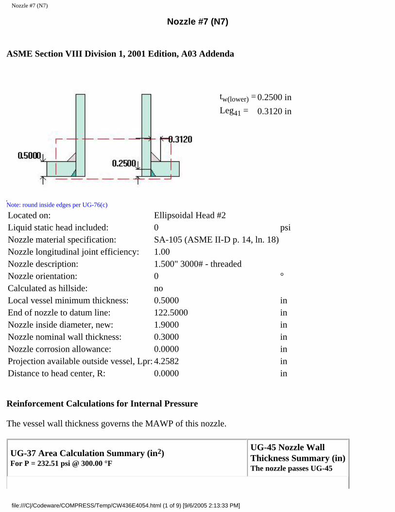
Nozzle #7 (N7)
Nozzle #7 (N7)
ASME Section VIII Division 1, 2001 Edition, A03 Addenda
tw(lower) = 0.2500 in
Leg41 = 0.3120 in
Note: round inside edges per UG-76(c)
Located on: Ellipsoidal Head #2Liquid static head included: 0 psiNozzle material specification: SA-105 (ASME II-D p. 14, ln. 18)Nozzle longitudinal joint efficiency: 1.00Nozzle description: 1.500" 3000# - threadedNozzle orientation: 0 °Calculated as hillside: noLocal vessel minimum thickness: 0.5000 inEnd of nozzle to datum line: 122.5000 inNozzle inside diameter, new: 1.9000 inNozzle nominal wall thickness: 0.3000 inNozzle corrosion allowance: 0.0000 inProjection available outside vessel, Lpr: 4.2582 inDistance to head center, R: 0.0000 in
Reinforcement Calculations for Internal Pressure
The vessel wall thickness governs the MAWP of this nozzle.
UG-37 Area Calculation Summary (in2)For P = 232.51 psi @ 300.00 °F
UG-45 Nozzle WallThickness Summary (in)The nozzle passes UG-45
file:///C|/Codeware/COMPRESS/Temp/CW436E4054.html (1 of 9) [9/6/2005 2:13:33 PM]

Nozzle #7 (N7)
Arequired
Aavailable
A1 A2 A3 A5Awelds
treq tmin
This nozzle is exempt from area calculations per UG-36(c)(3)(a) 0.0625 0.3000
Weld Failure Path Analysis Summary
The nozzle is exempt from weld strength calculations per UW-15(b)(2)
UW-16 Weld Sizing Summary
Weld descriptionRequired weldthroat size (in)
Actual weldthroat size (in)
Status
Nozzle to shell fillet (Leg41) 0.2100 0.2184 weld size is adequate
Nozzle to shell groove (Lower) 0.2100 0.2500 weld size is adequate
Calculations for internal pressure 232.51 psi @ 300.00 °F
Nozzle is impact test exempt to -155 °F per UCS-66(b)(3) (coincident ratio = 0.01926).
Nozzle UCS-66 governing thk: 0.3000 inNozzle rated MDMT: -155.00 °F
Limits of reinforcement per UG-40
Parallel to the vessel wall: d = 1.9000 in
Normal to the vessel wall outside: 2.5*(tn - Cn) + te = 0.7500 in
Nozzle required thickness per UG-27(c)(1)
trn = P*Rn/(Sn*E - 0.6*P)
= 232.5106*0.95/(20,000.00*1 - 0.6*232.5106)= 0.0111 in
Required thickness tr from UG-37(a)(3)
tr = P*K1*Do/(2*S*E + 0.8*P)
= 232.5106*0.9*96/(2*20,000.00*1 + 0.8*232.5106)= 0.4999 in
file:///C|/Codeware/COMPRESS/Temp/CW436E4054.html (2 of 9) [9/6/2005 2:13:33 PM]

Nozzle #7 (N7)
This opening does not require reinforcement per UG-36(c)(3)(a)
Area calculations for weld failure path analysis
Allowable stresses: Sn = 20,000.00, Sv = 20,000.00 psi
fr1 = lesser of 1 or Sn/Sv = 1
fr2 = lesser of 1 or Sn/Sv = 1
A = d*tr*F + 2*tn*tr*F*(1 - fr1)
= 1.9*0.4999*1 + 2*0.3*0.4999*1*(1 - 1)= 0.9498 in2
A1 = larger of the following= 0.0002 in2
= d*(E1*t - F*tr) - 2*tn*(E1*t - F*tr)*(1 - fr1)
= 1.9*(1*0.5 - 1*0.4999) - 2*0.3*(1*0.5 - 1*0.4999)*(1 - 1)= 0.0002 in2
= 2*(t + tn)*(E1*t - F*tr) - 2*tn*(E1*t - F*tr)*(1 - fr1)
= 2*(0.5 + 0.3)*(1*0.5 - 1*0.4999) - 2*0.3*(1*0.5 - 1*0.4999)*(1 - 1)= 0.0002 in2
A2 = smaller of the following= 0.4334 in2
= 5*(tn - trn)*fr2*t
= 5*(0.3 - 0.0111)*1*0.5= 0.7223 in2
= 5*(tn - trn)*fr2*tn= 5*(0.3 - 0.0111)*1*0.3= 0.4334 in2
A41 = Leg2*fr2
= 0.3122*1 =0.0973 in2
UW-16(d) Weld Check
tmin = lesser of 0.75 or tn or t = 0.3000 in
t1(min) or t2(min) = lesser of 0.25 or 0.7*tmin = 0.2100 in
file:///C|/Codeware/COMPRESS/Temp/CW436E4054.html (3 of 9) [9/6/2005 2:13:33 PM]

Nozzle #7 (N7)
t1(actual) = 0.7*Leg = 0.7*0.312 = 0.2184 in
The weld size t1 is satisfactory.
t2(actual) = 0.25 in
The weld size t2 is satisfactory.
t1 + t2 = 0.4684 >= 1.25*tmin
The combined weld sizes for t1 and t2 are satisfactory.
ASME B16.11 Coupling Wall Thickness Check
Interpretation VIII-1-83-66 has been applied.
Wall thickness req'd per ASME B16.11 2.1.1: tr1 = 0.0145 in (E =1)
Wall thickness per UG-16(b): tr3 = 0.0625 in
Available nozzle wall thickness new, tn = 0.3000 in
The nozzle neck thickness is adequate.
Reinforcement Calculations for MAP
The vessel wall thickness governs the MAP of this nozzle.
UG-37 Area Calculation Summary (in2)For P = 232.51 psi @ 70.00 °F
UG-45 Nozzle WallThickness Summary (in)The nozzle passes UG-45
Arequired
Aavailable
A1 A2 A3 A5Awelds
treq tmin
This nozzle is exempt from area calculations per UG-36(c)(3)(a) 0.0625 0.3000
Weld Failure Path Analysis Summary
The nozzle is exempt from weld strength calculations per UW-15(b)(2)
UW-16 Weld Sizing Summary
Weld descriptionRequired weldthroat size (in)
Actual weldthroat size (in)
Status
file:///C|/Codeware/COMPRESS/Temp/CW436E4054.html (4 of 9) [9/6/2005 2:13:33 PM]

Nozzle #7 (N7)
Nozzle to shell fillet (Leg41) 0.2100 0.2184 weld size is adequate
Nozzle to shell groove (Lower) 0.2100 0.2500 weld size is adequate
Calculations for internal pressure 232.51 psi @ 70.00 °F
Limits of reinforcement per UG-40
Parallel to the vessel wall: d = 1.9000 in
Normal to the vessel wall outside: 2.5*(tn - Cn) + te = 0.7500 in
Nozzle required thickness per UG-27(c)(1)
trn = P*Rn/(Sn*E - 0.6*P)
= 232.5106*0.95/(20,000.00*1 - 0.6*232.5106)= 0.0111 in
Required thickness tr from UG-37(a)(3)
tr = P*K1*Do/(2*S*E + 0.8*P)
= 232.5106*0.9*96/(2*20,000.00*1 + 0.8*232.5106)= 0.4999 in
This opening does not require reinforcement per UG-36(c)(3)(a)
Area calculations for weld failure path analysis
Allowable stresses: Sn = 20,000.00, Sv = 20,000.00 psi
fr1 = lesser of 1 or Sn/Sv = 1
fr2 = lesser of 1 or Sn/Sv = 1
A = d*tr*F + 2*tn*tr*F*(1 - fr1)
= 1.9*0.4999*1 + 2*0.3*0.4999*1*(1 - 1)= 0.9498 in2
A1 = larger of the following= 0.0002 in2
= d*(E1*t - F*tr) - 2*tn*(E1*t - F*tr)*(1 - fr1)
file:///C|/Codeware/COMPRESS/Temp/CW436E4054.html (5 of 9) [9/6/2005 2:13:33 PM]

Nozzle #7 (N7)
= 1.9*(1*0.5 - 1*0.4999) - 2*0.3*(1*0.5 - 1*0.4999)*(1 - 1)= 0.0002 in2
= 2*(t + tn)*(E1*t - F*tr) - 2*tn*(E1*t - F*tr)*(1 - fr1)
= 2*(0.5 + 0.3)*(1*0.5 - 1*0.4999) - 2*0.3*(1*0.5 - 1*0.4999)*(1 - 1)= 0.0002 in2
A2 = smaller of the following= 0.4334 in2
= 5*(tn - trn)*fr2*t
= 5*(0.3 - 0.0111)*1*0.5= 0.7223 in2
= 5*(tn - trn)*fr2*tn= 5*(0.3 - 0.0111)*1*0.3= 0.4334 in2
A41 = Leg2*fr2
= 0.3122*1 =0.0973 in2
UW-16(d) Weld Check
tmin = lesser of 0.75 or tn or t = 0.3000 in
t1(min) or t2(min) = lesser of 0.25 or 0.7*tmin = 0.2100 in
t1(actual) = 0.7*Leg = 0.7*0.312 = 0.2184 in
The weld size t1 is satisfactory.
t2(actual) = 0.25 in
The weld size t2 is satisfactory.
t1 + t2 = 0.4684 >= 1.25*tmin
The combined weld sizes for t1 and t2 are satisfactory.
ASME B16.11 Coupling Wall Thickness Check
Interpretation VIII-1-83-66 has been applied.
Wall thickness req'd per ASME B16.11 2.1.1: tr1 = 0.0145 in (E =1)
Wall thickness per UG-16(b): tr3 = 0.0625 in
Available nozzle wall thickness new, tn = 0.3000 in
file:///C|/Codeware/COMPRESS/Temp/CW436E4054.html (6 of 9) [9/6/2005 2:13:33 PM]

Nozzle #7 (N7)
The nozzle neck thickness is adequate.
Reinforcement Calculations for External Pressure
UG-37 Area Calculation Summary (in2)For Pe = 43.45 psi @ 300.00 °F
UG-45 Nozzle WallThickness Summary (in)The nozzle passes UG-45
Arequired
Aavailable
A1 A2 A3 A5Awelds
treq tmin
This nozzle is exempt from area calculations per UG-36(c)(3)(a) 0.1041 0.3000
Weld Failure Path Analysis Summary
Weld strength calculations are not required for external pressure
UW-16 Weld Sizing Summary
Weld descriptionRequired weldthroat size (in)
Actual weldthroat size (in)
Status
Nozzle to shell fillet (Leg41) 0.2100 0.2184 weld size is adequate
Nozzle to shell groove (Lower) 0.2100 0.2500 weld size is adequate
Calculations for external pressure 43.45 psi @ 300.00 °F
Limits of reinforcement per UG-40
Parallel to the vessel wall: d = 1.9000 in
Normal to the vessel wall outside: 2.5*(tn - Cn) + te = 0.7500 in
Nozzle required thickness per UG-28 trn = 0.0152 in
From UG-37(d)(1) required thickness tr = 0.4199 in
This opening does not require reinforcement per UG-36(c)(3)(a)
file:///C|/Codeware/COMPRESS/Temp/CW436E4054.html (7 of 9) [9/6/2005 2:13:33 PM]
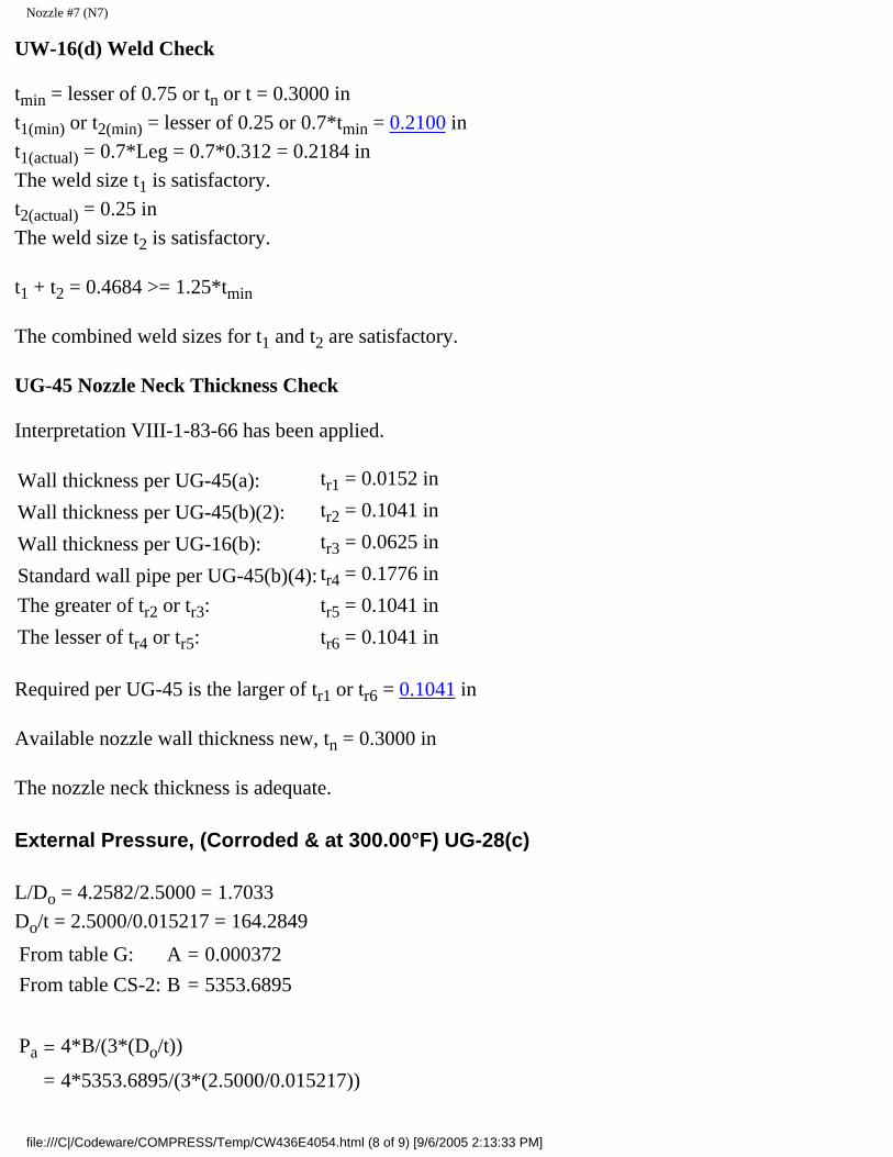
Nozzle #7 (N7)
UW-16(d) Weld Check
tmin = lesser of 0.75 or tn or t = 0.3000 in
t1(min) or t2(min) = lesser of 0.25 or 0.7*tmin = 0.2100 in
t1(actual) = 0.7*Leg = 0.7*0.312 = 0.2184 in
The weld size t1 is satisfactory.
t2(actual) = 0.25 in
The weld size t2 is satisfactory.
t1 + t2 = 0.4684 >= 1.25*tmin
The combined weld sizes for t1 and t2 are satisfactory.
UG-45 Nozzle Neck Thickness Check
Interpretation VIII-1-83-66 has been applied.
Wall thickness per UG-45(a): tr1 = 0.0152 in
Wall thickness per UG-45(b)(2): tr2 = 0.1041 in
Wall thickness per UG-16(b): tr3 = 0.0625 in
Standard wall pipe per UG-45(b)(4): tr4 = 0.1776 in
The greater of tr2 or tr3: tr5 = 0.1041 in
The lesser of tr4 or tr5: tr6 = 0.1041 in
Required per UG-45 is the larger of tr1 or tr6 = 0.1041 in
Available nozzle wall thickness new, tn = 0.3000 in
The nozzle neck thickness is adequate.
External Pressure, (Corroded & at 300.00°F) UG-28(c)
L/Do = 4.2582/2.5000 = 1.7033
Do/t = 2.5000/0.015217 = 164.2849
From table G: A = 0.000372
From table CS-2: B = 5353.6895
Pa = 4*B/(3*(Do/t))
= 4*5353.6895/(3*(2.5000/0.015217))
file:///C|/Codeware/COMPRESS/Temp/CW436E4054.html (8 of 9) [9/6/2005 2:13:33 PM]

Nozzle #7 (N7)
= 43.4504 psi
Design thickness for external pressure Pa = 43.4504 psi
= t + Corrosion = 0.015217 + 0.0000 = 0.0152"
file:///C|/Codeware/COMPRESS/Temp/CW436E4054.html (9 of 9) [9/6/2005 2:13:33 PM]

Nozzle #8 (N8)
Nozzle #8 (N8)
ASME Section VIII Division 1, 2001 Edition, A03 Addenda
tw(lower) = 0.2500 in
Leg41 = 0.3120 in
Note: round inside edges per UG-76(c)
Located on: Ellipsoidal Head #2Liquid static head included: 0 psiNozzle material specification: SA-105 (ASME II-D p. 14, ln. 18)Nozzle longitudinal joint efficiency: 1.00Nozzle description: 1.500" 3000# - threadedNozzle orientation: 180 °Calculated as hillside: yesLocal vessel minimum thickness: 0.5000 inEnd of nozzle to datum line: 119.5000 inNozzle inside diameter, new: 1.9000 inNozzle nominal wall thickness: 0.3000 inNozzle corrosion allowance: 0.0000 inOpening chord length: 1.9795 inProjection available outside vessel, Lpr: 4.1467 inDistance to head center, R: 24.0000 in
Reinforcement Calculations for Internal Pressure
The vessel wall thickness governs the MAWP of this nozzle.
file:///C|/Codeware/COMPRESS/Temp/CW21D40241.html (1 of 9) [9/6/2005 2:13:34 PM]

Nozzle #8 (N8)
UG-37 Area Calculation Summary (in2)For P = 232.51 psi @ 300.00 °F
UG-45 Nozzle WallThickness Summary (in)The nozzle passes UG-45
Arequired
Aavailable
A1 A2 A3 A5Awelds
treq tmin
This nozzle is exempt from area calculations per UG-36(c)(3)(a) 0.0625 0.3000
Weld Failure Path Analysis Summary
The nozzle is exempt from weld strength calculations per UW-15(b)(2)
UW-16 Weld Sizing Summary
Weld descriptionRequired weldthroat size (in)
Actual weldthroat size (in)
Status
Nozzle to shell fillet (Leg41) 0.2100 0.2184 weld size is adequate
Nozzle to shell groove (Lower) 0.2100 0.2500 weld size is adequate
Calculations for internal pressure 232.51 psi @ 300.00 °F
Nozzle is impact test exempt to -155 °F per UCS-66(b)(3) (coincident ratio = 0.01926).
Nozzle UCS-66 governing thk: 0.3000 inNozzle rated MDMT: -155.00 °F
Limits of reinforcement per UG-40
Parallel to the vessel wall: d = 1.9795 in
Normal to the vessel wall outside: 2.5*(tn - Cn) + te = 0.7500 in
Nozzle required thickness per UG-27(c)(1)
trn = P*Rn/(Sn*E - 0.6*P)
= 232.5106*0.95/(20,000.00*1 - 0.6*232.5106)= 0.0111 in
Required thickness tr from UG-37(a)(3)
tr = P*K1*Do/(2*S*E + 0.8*P)
file:///C|/Codeware/COMPRESS/Temp/CW21D40241.html (2 of 9) [9/6/2005 2:13:34 PM]

Nozzle #8 (N8)
= 232.5106*0.9*96/(2*20,000.00*1 + 0.8*232.5106)= 0.4999 in
This opening does not require reinforcement per UG-36(c)(3)(a)
Area calculations for weld failure path analysis
Allowable stresses: Sn = 20,000.00, Sv = 20,000.00 psi
fr1 = lesser of 1 or Sn/Sv = 1
fr2 = lesser of 1 or Sn/Sv = 1
A = d*tr*F + 2*tn*tr*F*(1 - fr1)
= 1.9795*0.4999*1 + 2*0.3*0.4999*1*(1 - 1)= 0.9896 in2
A1 = larger of the following= 0.0002 in2
= d*(E1*t - F*tr) - 2*tn*(E1*t - F*tr)*(1 - fr1)
= 1.9795*(1*0.5 - 1*0.4999) - 2*0.3*(1*0.5 - 1*0.4999)*(1 - 1)= 0.0002 in2
= 2*(t + tn)*(E1*t - F*tr) - 2*tn*(E1*t - F*tr)*(1 - fr1)
= 2*(0.5 + 0.3)*(1*0.5 - 1*0.4999) - 2*0.3*(1*0.5 - 1*0.4999)*(1 - 1)= 0.0002 in2
A2 = smaller of the following= 0.4334 in2
= 5*(tn - trn)*fr2*t
= 5*(0.3 - 0.0111)*1*0.5= 0.7223 in2
= 5*(tn - trn)*fr2*tn= 5*(0.3 - 0.0111)*1*0.3= 0.4334 in2
A41 = Leg2*fr2
= 0.3122*1 =0.0973 in2
UW-16(d) Weld Check
file:///C|/Codeware/COMPRESS/Temp/CW21D40241.html (3 of 9) [9/6/2005 2:13:34 PM]

Nozzle #8 (N8)
tmin = lesser of 0.75 or tn or t = 0.3000 in
t1(min) or t2(min) = lesser of 0.25 or 0.7*tmin = 0.2100 in
t1(actual) = 0.7*Leg = 0.7*0.312 = 0.2184 in
The weld size t1 is satisfactory.
t2(actual) = 0.25 in
The weld size t2 is satisfactory.
t1 + t2 = 0.4684 >= 1.25*tmin
The combined weld sizes for t1 and t2 are satisfactory.
ASME B16.11 Coupling Wall Thickness Check
Interpretation VIII-1-83-66 has been applied.
Wall thickness req'd per ASME B16.11 2.1.1: tr1 = 0.0145 in (E =1)
Wall thickness per UG-16(b): tr3 = 0.0625 in
Available nozzle wall thickness new, tn = 0.3000 in
The nozzle neck thickness is adequate.
Reinforcement Calculations for MAP
The vessel wall thickness governs the MAP of this nozzle.
UG-37 Area Calculation Summary (in2)For P = 232.51 psi @ 70.00 °F
UG-45 Nozzle WallThickness Summary (in)The nozzle passes UG-45
Arequired
Aavailable
A1 A2 A3 A5Awelds
treq tmin
This nozzle is exempt from area calculations per UG-36(c)(3)(a) 0.0625 0.3000
Weld Failure Path Analysis Summary
The nozzle is exempt from weld strength calculations per UW-15(b)(2)
UW-16 Weld Sizing Summary
file:///C|/Codeware/COMPRESS/Temp/CW21D40241.html (4 of 9) [9/6/2005 2:13:34 PM]
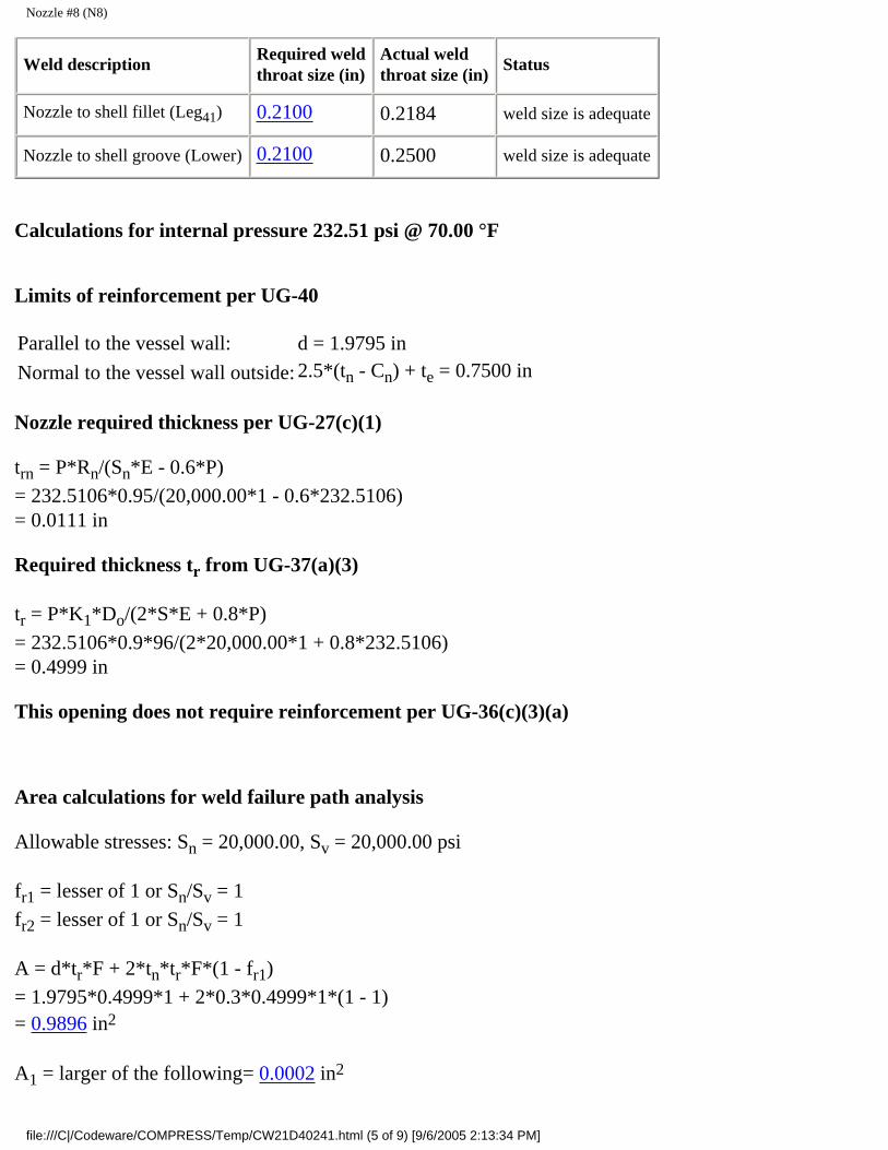
Nozzle #8 (N8)
Weld descriptionRequired weldthroat size (in)
Actual weldthroat size (in)
Status
Nozzle to shell fillet (Leg41) 0.2100 0.2184 weld size is adequate
Nozzle to shell groove (Lower) 0.2100 0.2500 weld size is adequate
Calculations for internal pressure 232.51 psi @ 70.00 °F
Limits of reinforcement per UG-40
Parallel to the vessel wall: d = 1.9795 in
Normal to the vessel wall outside: 2.5*(tn - Cn) + te = 0.7500 in
Nozzle required thickness per UG-27(c)(1)
trn = P*Rn/(Sn*E - 0.6*P)
= 232.5106*0.95/(20,000.00*1 - 0.6*232.5106)= 0.0111 in
Required thickness tr from UG-37(a)(3)
tr = P*K1*Do/(2*S*E + 0.8*P)
= 232.5106*0.9*96/(2*20,000.00*1 + 0.8*232.5106)= 0.4999 in
This opening does not require reinforcement per UG-36(c)(3)(a)
Area calculations for weld failure path analysis
Allowable stresses: Sn = 20,000.00, Sv = 20,000.00 psi
fr1 = lesser of 1 or Sn/Sv = 1
fr2 = lesser of 1 or Sn/Sv = 1
A = d*tr*F + 2*tn*tr*F*(1 - fr1)
= 1.9795*0.4999*1 + 2*0.3*0.4999*1*(1 - 1)= 0.9896 in2
A1 = larger of the following= 0.0002 in2
file:///C|/Codeware/COMPRESS/Temp/CW21D40241.html (5 of 9) [9/6/2005 2:13:34 PM]

Nozzle #8 (N8)
= d*(E1*t - F*tr) - 2*tn*(E1*t - F*tr)*(1 - fr1)
= 1.9795*(1*0.5 - 1*0.4999) - 2*0.3*(1*0.5 - 1*0.4999)*(1 - 1)= 0.0002 in2
= 2*(t + tn)*(E1*t - F*tr) - 2*tn*(E1*t - F*tr)*(1 - fr1)
= 2*(0.5 + 0.3)*(1*0.5 - 1*0.4999) - 2*0.3*(1*0.5 - 1*0.4999)*(1 - 1)= 0.0002 in2
A2 = smaller of the following= 0.4334 in2
= 5*(tn - trn)*fr2*t
= 5*(0.3 - 0.0111)*1*0.5= 0.7223 in2
= 5*(tn - trn)*fr2*tn= 5*(0.3 - 0.0111)*1*0.3= 0.4334 in2
A41 = Leg2*fr2
= 0.3122*1 =0.0973 in2
UW-16(d) Weld Check
tmin = lesser of 0.75 or tn or t = 0.3000 in
t1(min) or t2(min) = lesser of 0.25 or 0.7*tmin = 0.2100 in
t1(actual) = 0.7*Leg = 0.7*0.312 = 0.2184 in
The weld size t1 is satisfactory.
t2(actual) = 0.25 in
The weld size t2 is satisfactory.
t1 + t2 = 0.4684 >= 1.25*tmin
The combined weld sizes for t1 and t2 are satisfactory.
ASME B16.11 Coupling Wall Thickness Check
Interpretation VIII-1-83-66 has been applied.
Wall thickness req'd per ASME B16.11 2.1.1: tr1 = 0.0145 in (E =1)
Wall thickness per UG-16(b): tr3 = 0.0625 in
file:///C|/Codeware/COMPRESS/Temp/CW21D40241.html (6 of 9) [9/6/2005 2:13:34 PM]

Nozzle #8 (N8)
Available nozzle wall thickness new, tn = 0.3000 in
The nozzle neck thickness is adequate.
Reinforcement Calculations for External Pressure
UG-37 Area Calculation Summary (in2)For Pe = 43.45 psi @ 300.00 °F
UG-45 Nozzle WallThickness Summary (in)The nozzle passes UG-45
Arequired
Aavailable
A1 A2 A3 A5Awelds
treq tmin
This nozzle is exempt from area calculations per UG-36(c)(3)(a) 0.1041 0.3000
Weld Failure Path Analysis Summary
Weld strength calculations are not required for external pressure
UW-16 Weld Sizing Summary
Weld descriptionRequired weldthroat size (in)
Actual weldthroat size (in)
Status
Nozzle to shell fillet (Leg41) 0.2100 0.2184 weld size is adequate
Nozzle to shell groove (Lower) 0.2100 0.2500 weld size is adequate
Calculations for external pressure 43.45 psi @ 300.00 °F
Limits of reinforcement per UG-40
Parallel to the vessel wall: d = 1.9793 in
Normal to the vessel wall outside: 2.5*(tn - Cn) + te = 0.7500 in
Nozzle required thickness per UG-28 trn = 0.0162 in
From UG-37(d)(1) required thickness tr = 0.4199 in
file:///C|/Codeware/COMPRESS/Temp/CW21D40241.html (7 of 9) [9/6/2005 2:13:34 PM]

Nozzle #8 (N8)
This opening does not require reinforcement per UG-36(c)(3)(a)
UW-16(d) Weld Check
tmin = lesser of 0.75 or tn or t = 0.3000 in
t1(min) or t2(min) = lesser of 0.25 or 0.7*tmin = 0.2100 in
t1(actual) = 0.7*Leg = 0.7*0.312 = 0.2184 in
The weld size t1 is satisfactory.
t2(actual) = 0.25 in
The weld size t2 is satisfactory.
t1 + t2 = 0.4684 >= 1.25*tmin
The combined weld sizes for t1 and t2 are satisfactory.
UG-45 Nozzle Neck Thickness Check
Interpretation VIII-1-83-66 has been applied.
Wall thickness per UG-45(a): tr1 = 0.0162 in
Wall thickness per UG-45(b)(2): tr2 = 0.1041 in
Wall thickness per UG-16(b): tr3 = 0.0625 in
Standard wall pipe per UG-45(b)(4): tr4 = 0.1776 in
The greater of tr2 or tr3: tr5 = 0.1041 in
The lesser of tr4 or tr5: tr6 = 0.1041 in
Required per UG-45 is the larger of tr1 or tr6 = 0.1041 in
Available nozzle wall thickness new, tn = 0.3000 in
The nozzle neck thickness is adequate.
External Pressure, (Corroded & at 300.00°F) UG-28(c)
L/Do = 4.8764/2.5000 = 1.9505
Do/t = 2.5000/0.016247 = 153.8740
From table G: A = 0.000349
From table CS-2: B = 5014.5625
file:///C|/Codeware/COMPRESS/Temp/CW21D40241.html (8 of 9) [9/6/2005 2:13:34 PM]

Nozzle #8 (N8)
Pa = 4*B/(3*(Do/t))
= 4*5014.5625/(3*(2.5000/0.016247))
= 43.4517 psi
Design thickness for external pressure Pa = 43.4517 psi
= t + Corrosion = 0.016247 + 0.0000 = 0.0162"
file:///C|/Codeware/COMPRESS/Temp/CW21D40241.html (9 of 9) [9/6/2005 2:13:34 PM]

Nozzle #9 (N9)
Nozzle #9 (N9)
ASME Section VIII Division 1, 2001 Edition, A03 Addenda
tw(lower) = 0.1870 in
Leg41 = 0.2500 in
Note: round inside edges per UG-76(c)
Located on: Cylinder #1Liquid static head included: 0.6735 psiNozzle material specification: SA-105 (ASME II-D p. 14, ln. 18)Nozzle longitudinal joint efficiency: 1.00Nozzle description: 1" 3000# - threadedNozzle orientation: 180 °Local vessel minimum thickness: 0.5000 inNozzle center line offset to datum line: 82.0000 inEnd of nozzle to shell center: 52.0000 inNozzle inside diameter, new: 1.3150 inNozzle nominal wall thickness: 0.2175 inNozzle corrosion allowance: 0.0000 inProjection available outside vessel, Lpr: 4.0000 in
Reinforcement Calculations for Internal Pressure
The vessel wall thickness governs the MAWP of this nozzle.
UG-37 Area Calculation Summary (in2)For P = 209.15 psi @ 300.00 °F
UG-45 Nozzle WallThickness Summary (in)The nozzle passes UG-45
file:///C|/Codeware/COMPRESS/Temp/CW1AA89872.html (1 of 8) [9/6/2005 2:13:35 PM]

Nozzle #9 (N9)
Arequired
Aavailable
A1 A2 A3 A5Awelds
treq tmin
This nozzle is exempt from area calculations per UG-36(c)(3)(a) 0.0625 0.2175
Weld Failure Path Analysis Summary
The nozzle is exempt from weld strength calculations per UW-15(b)(2)
UW-16 Weld Sizing Summary
Weld descriptionRequired weldthroat size (in)
Actual weldthroat size (in)
Status
Nozzle to shell fillet (Leg41) 0.1523 0.1750 weld size is adequate
Nozzle to shell groove (Lower) 0.1523 0.1870 weld size is adequate
Calculations for internal pressure 209.15 psi @ 300.00 °F
Nozzle is impact test exempt to -155 °F per UCS-66(b)(3) (coincident ratio = 0.01849).
Nozzle UCS-66 governing thk: 0.2175 inNozzle rated MDMT: -155.00 °F
Limits of reinforcement per UG-40
Parallel to the vessel wall: (Rn + tn + t )= 1.3750 in
Normal to the vessel wall outside: 2.5*(tn - Cn) + te = 0.5438 in
Nozzle required thickness per UG-27(c)(1)
trn = P*Rn/(Sn*E - 0.6*P)
= 209.1505*0.6575/(20,000.00*1 - 0.6*209.1505)= 0.0069 in
Required thickness tr from UG-37(a)
tr = P*Ro/(S*E + 0.4*P)
= 209.1505*48/(20,000.00*1 + 0.4*209.1505)= 0.4999 in
file:///C|/Codeware/COMPRESS/Temp/CW1AA89872.html (2 of 8) [9/6/2005 2:13:35 PM]

Nozzle #9 (N9)
This opening does not require reinforcement per UG-36(c)(3)(a)
Area calculations for weld failure path analysis
Allowable stresses: Sn = 20,000.00, Sv = 20,000.00 psi
fr1 = lesser of 1 or Sn/Sv = 1
fr2 = lesser of 1 or Sn/Sv = 1
A = d*tr*F + 2*tn*tr*F*(1 - fr1)
= 1.315*0.49987*1 + 2*0.2175*0.49987*1*(1 - 1)= 0.6573 in2
A1 = larger of the following= 0.0002 in2
= d*(E1*t - F*tr) - 2*tn*(E1*t - F*tr)*(1 - fr1)
= 1.315*(1*0.5 - 1*0.49987) - 2*0.2175*(1*0.5 - 1*0.49987)*(1 - 1)= 0.0002 in2
= 2*(t + tn)*(E1*t - F*tr) - 2*tn*(E1*t - F*tr)*(1 - fr1)
= 2*(0.5 + 0.2175)*(1*0.5 - 1*0.49987) - 2*0.2175*(1*0.5 - 1*0.49987)*(1 - 1)= 0.0002 in2
A2 = smaller of the following= 0.2290 in2
= 5*(tn - trn)*fr2*t
= 5*(0.2175 - 0.0069)*1*0.5= 0.5265 in2
= 5*(tn - trn)*fr2*tn= 5*(0.2175 - 0.0069)*1*0.2175= 0.2290 in2
A41 = Leg2*fr2
= 0.252*1 =0.0625 in2
UW-16(d) Weld Check
tmin = lesser of 0.75 or tn or t = 0.2175 in
t1(min) or t2(min) = lesser of 0.25 or 0.7*tmin = 0.1522 in
file:///C|/Codeware/COMPRESS/Temp/CW1AA89872.html (3 of 8) [9/6/2005 2:13:35 PM]

Nozzle #9 (N9)
t1(actual) = 0.7*Leg = 0.7*0.25 = 0.175 in
The weld size t1 is satisfactory.
t2(actual) = 0.187 in
The weld size t2 is satisfactory.
t1 + t2 = 0.362 >= 1.25*tmin
The combined weld sizes for t1 and t2 are satisfactory.
ASME B16.11 Coupling Wall Thickness Check
Wall thickness req'd per ASME B16.11 2.1.1: tr1 = 0.0091 in (E =1)
Wall thickness per UG-16(b): tr3 = 0.0625 in
Available nozzle wall thickness new, tn = 0.2175 in
The nozzle neck thickness is adequate.
Reinforcement Calculations for MAP
The vessel wall thickness governs the MAP of this nozzle.
UG-37 Area Calculation Summary (in2)For P = 209.16 psi @ 70.00 °F
UG-45 Nozzle WallThickness Summary (in)The nozzle passes UG-45
Arequired
Aavailable
A1 A2 A3 A5Awelds
treq tmin
This nozzle is exempt from area calculations per UG-36(c)(3)(a) 0.0625 0.2175
Weld Failure Path Analysis Summary
The nozzle is exempt from weld strength calculations per UW-15(b)(2)
UW-16 Weld Sizing Summary
Weld descriptionRequired weldthroat size (in)
Actual weldthroat size (in)
Status
Nozzle to shell fillet (Leg41) 0.1523 0.1750 weld size is adequate
Nozzle to shell groove (Lower) 0.1523 0.1870 weld size is adequate
file:///C|/Codeware/COMPRESS/Temp/CW1AA89872.html (4 of 8) [9/6/2005 2:13:35 PM]

Nozzle #9 (N9)
Calculations for internal pressure 209.16 psi @ 70.00 °F
Limits of reinforcement per UG-40
Parallel to the vessel wall: (Rn + tn + t )= 1.3750 in
Normal to the vessel wall outside: 2.5*(tn - Cn) + te = 0.5438 in
Nozzle required thickness per UG-27(c)(1)
trn = P*Rn/(Sn*E - 0.6*P)
= 209.1551*0.6575/(20,000.00*1 - 0.6*209.1551)= 0.0069 in
Required thickness tr from UG-37(a)
tr = P*Ro/(S*E + 0.4*P)
= 209.1551*48/(20,000.00*1 + 0.4*209.1551)= 0.4999 in
This opening does not require reinforcement per UG-36(c)(3)(a)
Area calculations for weld failure path analysis
Allowable stresses: Sn = 20,000.00, Sv = 20,000.00 psi
fr1 = lesser of 1 or Sn/Sv = 1
fr2 = lesser of 1 or Sn/Sv = 1
A = d*tr*F + 2*tn*tr*F*(1 - fr1)
= 1.315*0.49988*1 + 2*0.2175*0.49988*1*(1 - 1)= 0.6573 in2
A1 = larger of the following= 0.0002 in2
= d*(E1*t - F*tr) - 2*tn*(E1*t - F*tr)*(1 - fr1)
= 1.315*(1*0.5 - 1*0.49988) - 2*0.2175*(1*0.5 - 1*0.49988)*(1 - 1)= 0.0002 in2
file:///C|/Codeware/COMPRESS/Temp/CW1AA89872.html (5 of 8) [9/6/2005 2:13:35 PM]

Nozzle #9 (N9)
= 2*(t + tn)*(E1*t - F*tr) - 2*tn*(E1*t - F*tr)*(1 - fr1)
= 2*(0.5 + 0.2175)*(1*0.5 - 1*0.49988) - 2*0.2175*(1*0.5 - 1*0.49988)*(1 - 1)= 0.0002 in2
A2 = smaller of the following= 0.2290 in2
= 5*(tn - trn)*fr2*t
= 5*(0.2175 - 0.0069)*1*0.5= 0.5265 in2
= 5*(tn - trn)*fr2*tn= 5*(0.2175 - 0.0069)*1*0.2175= 0.2290 in2
A41 = Leg2*fr2
= 0.252*1 =0.0625 in2
UW-16(d) Weld Check
tmin = lesser of 0.75 or tn or t = 0.2175 in
t1(min) or t2(min) = lesser of 0.25 or 0.7*tmin = 0.1522 in
t1(actual) = 0.7*Leg = 0.7*0.25 = 0.175 in
The weld size t1 is satisfactory.
t2(actual) = 0.187 in
The weld size t2 is satisfactory.
t1 + t2 = 0.362 >= 1.25*tmin
The combined weld sizes for t1 and t2 are satisfactory.
ASME B16.11 Coupling Wall Thickness Check
Wall thickness req'd per ASME B16.11 2.1.1: tr1 = 0.0091 in (E =1)
Wall thickness per UG-16(b): tr3 = 0.0625 in
Available nozzle wall thickness new, tn = 0.2175 in
The nozzle neck thickness is adequate.
Reinforcement Calculations for External Pressure
file:///C|/Codeware/COMPRESS/Temp/CW1AA89872.html (6 of 8) [9/6/2005 2:13:35 PM]

Nozzle #9 (N9)
UG-37 Area Calculation Summary (in2)For Pe = 43.45 psi @ 300.00 °F
UG-45 Nozzle WallThickness Summary (in)The nozzle passes UG-45
Arequired
Aavailable
A1 A2 A3 A5Awelds
treq tmin
This nozzle is exempt from area calculations per UG-36(c)(3)(a) 0.1042 0.2175
Weld Failure Path Analysis Summary
Weld strength calculations are not required for external pressure
UW-16 Weld Sizing Summary
Weld descriptionRequired weldthroat size (in)
Actual weldthroat size (in)
Status
Nozzle to shell fillet (Leg41) 0.1523 0.1750 weld size is adequate
Nozzle to shell groove (Lower) 0.1523 0.1870 weld size is adequate
Calculations for external pressure 43.45 psi @ 300.00 °F
Limits of reinforcement per UG-40
Parallel to the vessel wall: (Rn + tn + t )= 1.3750 in
Normal to the vessel wall outside: 2.5*(tn - Cn) + te = 0.5438 in
Nozzle required thickness per UG-28 trn = 0.0122 in
From UG-37(d)(1) required thickness tr = 0.5000 in
This opening does not require reinforcement per UG-36(c)(3)(a)
UW-16(d) Weld Check
tmin = lesser of 0.75 or tn or t = 0.2175 in
t1(min) or t2(min) = lesser of 0.25 or 0.7*tmin = 0.1522 in
file:///C|/Codeware/COMPRESS/Temp/CW1AA89872.html (7 of 8) [9/6/2005 2:13:35 PM]

Nozzle #9 (N9)
t1(actual) = 0.7*Leg = 0.7*0.25 = 0.175 in
The weld size t1 is satisfactory.
t2(actual) = 0.187 in
The weld size t2 is satisfactory.
t1 + t2 = 0.362 >= 1.25*tmin
The combined weld sizes for t1 and t2 are satisfactory.
UG-45 Nozzle Neck Thickness Check
Wall thickness per UG-45(a): tr1 = 0.0122 in
Wall thickness per UG-45(b)(2): tr2 = 0.1042 in
Wall thickness per UG-16(b): tr3 = 0.0625 in
Standard wall pipe per UG-45(b)(4): tr4 = 0.1269 in
The greater of tr2 or tr3: tr5 = 0.1042 in
The lesser of tr4 or tr5: tr6 = 0.1042 in
Required per UG-45 is the larger of tr1 or tr6 = 0.1042 in
Available nozzle wall thickness new, tn = 0.2175 in
The nozzle neck thickness is adequate.
External Pressure, (Corroded & at 300.00°F) UG-28(c)
L/Do = 4.0080/1.7500 = 2.2903
Do/t = 1.7500/0.012167 = 143.8263
From table G: A = 0.000326
From table CS-2: B = 4687.1914
Pa = 4*B/(3*(Do/t))
= 4*4687.1914/(3*(1.7500/0.012167))
= 43.4523 psi
Design thickness for external pressure Pa = 43.4523 psi
= t + Corrosion = 0.012167 + 0.0000 = 0.0122"
file:///C|/Codeware/COMPRESS/Temp/CW1AA89872.html (8 of 8) [9/6/2005 2:13:35 PM]

Legs #1
Legs #1
Leg material:Leg description: 5x5x1/2 Equal Angle (Leg in)Number of legs: N = 4Overall length: 56.5000 inBase to girth seam length: 44.5000 inBolt circle: 94.0000 inAnchor bolt size: 1 inch series 8 threadedAnchor bolt material:Anchor bolts/leg: 1
Anchor bolt allowable stress: Sb = 20,000 psi
Anchor bolt corrosion allowance: 0.0000 inAnchor bolt hole clearance: 0.0620 inBase plate width: 9.0000 inBase plate length: 9.0000 in
Base plate thickness: 0.5625 in (0.5368 in required)
Base plate allowable stress: 24,000 psiFoundation allowable bearing stress: 750 psiEffective length coefficient: K = 1.2
Coefficient: Cm = 0.85
Leg yield stress: Fy = 36,000 psi
Leg elastic modulus: E = 29,000,000 psi
Leg to shell fillet weld: 0.2500 in (0.0653 in required)
Legs braced: No
Note: The support attachment point is assumed to be 1 in up from the cylinder circumferential seam.
LoadingForceattackangle °
Legposition °
Axialend load
lbf
Shearresisted
lbf
Axialfapsi
Bendingfbxpsi
Bendingfbypsi
RatioH1-1
RatioH1-2
Weightoperatingcorroded
Moment =13.3 lb-ft
0
0 9,409.1 0.0 1,981 4,645 0 0.2864 0.2872
90 9,410.8 0.0 1,981 4,645 0 0.2864 0.2872
180 9,412.4 0.0 1,982 4,646 0 0.2865 0.2873
270 9,410.8 0.0 1,981 4,645 0 0.2864 0.2872
file:///C|/Codeware/COMPRESS/Temp/CW63797A2B.html (1 of 10) [9/6/2005 2:13:36 PM]

Legs #1
LoadingForceattackangle °
Legposition °
Axialend load
lbf
Shearresisted
lbf
Axialfapsi
Bendingfbxpsi
Bendingfbypsi
RatioH1-1
RatioH1-2
Weightempty
corroded
Moment =13.3 lb-ft
0
0 1,873.0 0.0 394 925 0 0.0552 0.0572
90 1,874.7 0.0 395 925 0 0.0552 0.0572
180 1,876.4 0.0 395 926 0 0.0553 0.0573
270 1,874.7 0.0 395 925 0 0.0552 0.0572
LoadingForceattackangle °
Legposition °
Axialend load
lbf
Shearresisted
lbf
Axialfapsi
Bendingfbxpsi
Bendingfbypsi
RatioH1-1
RatioH1-2
Weightvacuumcorroded
Moment =13.3 lb-ft
0
0 9,409.1 0.0 1,981 4,645 0 0.2864 0.2872
90 9,410.8 0.0 1,981 4,645 0 0.2864 0.2872
180 9,412.4 0.0 1,982 4,646 0 0.2865 0.2873
270 9,410.8 0.0 1,981 4,645 0 0.2864 0.2872
LoadingForceattackangle °
Legposition °
Axialend load (1)
lbf
Shearresisted
lbf
Axialfapsi
Bendingfbxpsi
Bendingfbypsi
RatioH1-1
RatioH1-2
GoverningCondition
Seismicoperatingcorroded
Moment =10,838.0 lb-ft
0
0 9,831.6 250.8 2,070 8,331 0 0.3292 0.3434
90 11,186.3 971.3 2,355 5,522 8,126 0.4880 0.5257
180 12,541.1 250.8 2,640 9,668 0 0.3964 0.4070
270 11,186.3 971.3 2,355 5,522 8,126 0.4880 0.5257
45
0 9,831.6 611.1 2,070 10,844 3,615 0.5030 0.5418
90 9,831.6 611.1 2,070 10,844 3,615 0.5030 0.5418
180 12,541.1 611.1 2,640 12,181 3,615 0.5717 0.6054
270 12,541.1 611.1 2,640 12,181 3,615 0.5717 0.6054
(1) Axial end load includes consideration of seismic vertical acceleration.
file:///C|/Codeware/COMPRESS/Temp/CW63797A2B.html (2 of 10) [9/6/2005 2:13:36 PM]

Legs #1
LoadingForceattackangle °
Legposition °
Axialend load (1)
lbf
Shearresisted
lbf
Axialfapsi
Bendingfbxpsi
Bendingfbypsi
RatioH1-1
RatioH1-2
Seismicempty
corroded
Moment =2,472.7 lb-ft
0
0 1,833.9 50.0 386 1,598 0 0.0607 0.0655
90 2,143.0 193.5 451 1,058 1,619 0.0932 0.1027
180 2,452.1 50.0 516 1,903 0 0.0749 0.0800
270 2,143.0 193.5 451 1,058 1,619 0.0932 0.1027
45
0 1,833.9 121.7 386 2,099 720 0.0945 0.1050
90 1,833.9 121.7 386 2,099 720 0.0945 0.1050
180 2,452.1 121.7 516 2,404 720 0.1087 0.1195
270 2,452.1 121.7 516 2,404 720 0.1087 0.1195
(1) Axial end load includes consideration of seismic vertical acceleration.
LoadingForceattackangle °
Legposition °
Axialend load (1)
lbf
Shearresisted
lbf
Axialfapsi
Bendingfbxpsi
Bendingfbypsi
RatioH1-1
RatioH1-2
Seismicvacuumcorroded
Moment =10,838.0 lb-ft
0
0 9,831.6 250.8 2,070 8,331 0 0.3292 0.3434
90 11,186.3 971.3 2,355 5,522 8,126 0.4880 0.5257
180 12,541.1 250.8 2,640 9,668 0 0.3964 0.4070
270 11,186.3 971.3 2,355 5,522 8,126 0.4880 0.5257
45
0 9,831.6 611.1 2,070 10,844 3,615 0.5030 0.5418
90 9,831.6 611.1 2,070 10,844 3,615 0.5030 0.5418
180 12,541.1 611.1 2,640 12,181 3,615 0.5717 0.6054
270 12,541.1 611.1 2,640 12,181 3,615 0.5717 0.6054
(1) Axial end load includes consideration of seismic vertical acceleration.
Leg Calculations (AISC manual ninth edition)
Axial end load, P1
P1 = Wt/N + 48*Mt/(N*D) + Vv/N
= 37,287.70/ 4 + 48*10,837.96/( 4*96) + 7,457.54/ 4
file:///C|/Codeware/COMPRESS/Temp/CW63797A2B.html (3 of 10) [9/6/2005 2:13:36 PM]

Legs #1
= 12,541.0547 lb
Allowable axial compressive stress, Fa (AISC chapter E)
Local buckling check (AISC 5-99)
b/t = (5/0.5) < (76 / Sqr(36)) so Qs = 1
Flexural-torsional buckling (AISC 5-317)
Shear center distance wo = 1.668771
ro2 = wo
2 + (Iz + Iw)/A
= 1.6687712 + (4.638599 + 17.96097)/4.75= 7.542601
Torsional constant J = 0.3958333Shear modulus G = 11,165.00 kips/in2
Fej = G*J / (A*ro2)
= 11,165.00*0.3958333 / (4.75*7.542601)= 123.3549
K*l/rw = 1.2*42.5/1.944545 = 26.22721
Few = π2*E/(Kl/rw)2
= π2*29,000.00/(26.22721)2
= 416.0959
H = 1 - (wo2 / ro
2)
= 1 - (1.6687712 / 7.542601)= 0.6307908
Fe = ((Few + Fej)/(2*H))*(1 - Sqr(1 - (4*Few*Fej*H)/(Few + Fej)2))
= ((416.0959 + 123.3549)/(2*0.6307908))*(1 - Sqr(1 - (4*416.0959*123.3549*0.6307908)/(416.0959 + 123.3549)2))= 109.0541
Equivalent slenderness ratio
Kl/r = π*Sqr(E/Fe)
= π*Sqr(29,000.00/109.0541)= 51.23041
file:///C|/Codeware/COMPRESS/Temp/CW63797A2B.html (4 of 10) [9/6/2005 2:13:36 PM]

Legs #1
Cc = Sqr(2*π2*E/(Fy*Qs))
= Sqr(2*π2*29,000,000/(36,000.00*1))= 126.0993
K*l/r= 1.2*42.5/0.988204 = 51.60878
Fa = 1.3 * (1 - (Kl/r)2/(2*Cc2))*Fy / (5/3 + 3*(Kl/r)/(8*Cc)-(Kl/r)3/(8*Cc
3))
= 1.3 * (1 - (51.60878)2/(2*126.09932))*36,000.00 / (5/3 + 3*(51.60878)/(8*126.0993)-(51.60878)3/(8*126.09933))= 23,670.26 psi
Allowable axial compression and bending (AISC chapter H)
Note: r is divided by 1.35 - See AISC 6.1.4, pg. 5-314
F'ex = 1.3*12*π2*E/(23*(Kl/r)2)
= 1.3*12*π2*29,000,000/(23*(69.67185)2)= 39,992.61 psi
F'ey = 1.3*12*π2*E/(23*(Kl/r)2)
= 1.3*12*π2*29,000,000/(23*(35.40673)2)= 154,854.1 psi
Fb = 1.3*0.66*Fy
= 30,888.00 psi
Compressive axial stress
fa = P1/A
= 12,541.05/4.75= 2,640.222 psi
Bending stresses
fbx = F*Cos(α)*L/(Ix/Cx) + P1*Ecc/(Ix/Cx)
= 611.0774*Cos(135)*42.5/(4.638599/1.513175) + 12,541.05*1.5132/(4.638599/1.513175)= 12,181.23 psi
fby= F*Sin(α)*L/(Iy/Cy)
= 611.0774*Sin(135)*42.5/(17.96097/3.5355)= 3,614.859 psi
file:///C|/Codeware/COMPRESS/Temp/CW63797A2B.html (5 of 10) [9/6/2005 2:13:36 PM]

Legs #1
AISC equation H1-1
H1-1 = fa/Fa + Cmx*fbx/((1 - fa/F'ex)*Fbx) + Cmy*fby/((1 - fa/F'
ey)*Fby)
= 2,640.222/23,670.26 + 0.85*12,181.23/((1 - 2,640.222/39,992.61)*30,888.00) + 0.85*3,614.859/((1 - 2,640.222/154,854.1)*30,888.00)= 0.5716505
AISC equation H1-2
H1-2 = fa/(0.6*1.3*Fy) + fbx/Fbx + fby/Fby
= 2,640.222/(0.6*1.3*36,000.00) + 12,181.23/30,888.00 + 3,614.859/30,888.00= 0.6054239
4, 5x5x1/2 Equal Angle legs are adequate.
Anchor bolts - Seismic empty corroded condition governs
Tensile loading per leg (1 bolt per leg)
R = 48*M/(N*BC) - W/N= 48*4,268.145/(4*94) - 7,498.783/4= -1,329.826 lbf
There is no net uplift (R is negative).
1 inch series 8 threaded bolts are satisfactory.
Check the leg to vessel fillet weld, Bednar 10.3, Seismic operating corroded governs
Note: continuous welding is assumed for all support leg fillet welds.
The following leg attachment weld analysis assumes the fillet weld is present on three sides (leg top closure plate is used).
Zw = (2*b*d + d2)/3
= (2*7.0711*14 + 142)/3= 131.3303
Jw = (b + 2*d)3/12 - d2*(b + d)2/(b + 2*d)
= (7.0711 + 2*14)3/12 - 142*(7.0711 + 14)2/(7.0711 + 2*14)= 1,113.425
E = d2/(b + 2*d)= 142/(7.0711 + 2*14)
file:///C|/Codeware/COMPRESS/Temp/CW63797A2B.html (6 of 10) [9/6/2005 2:13:36 PM]

Legs #1
= 5.588647
Governing weld load fx = Cos(90)*971.3052 = 0 lbf
Governing weld load fy = Sin(90)*971.3052 = 971.3052 lbf
f1 = P1/Lweld
= 11,186.31/35.0711= 318.9609 lbf/in (VL direct shear)
f2= fy*Lleg*0.5*b/Jw
= 971.3052*42.5*0.5*7.0711/1,113.425= 131.0813 lbf/in (VL torsion shear)
f3 = fy/Lweld
= 971.3052/35.0711= 27.69532 lbf/in (Vc direct shear)
f4 = fy*Lleg*E/Jw
= 971.3052*42.5*5.588647/1,113.425= 207.2003 lbf/in (Vc torsion shear)
f5 = fx*Lleg/Zw
= 0*42.5/131.3303= 0 lbf/in (ML bending)
f6 = fx/Lweld
= 0/35.0711= 0 lbf/in (Direct outward radial shear)
f = Sqr((f1 + f2)2 + (f3 + f4)2 + (f5 + f6)2)
= Sqr((318.9609 + 131.0813)2 + (27.69532 + 207.2003)2 + (0 + 0)2)= 507.6553 lbf/in (Resultant shear load)
Required leg to vessel fillet weld leg size (welded both sides + top)
tw = f / (0.707*0.55*Sa)
= 507.6553 / (0.707*0.55*20,000.00)= 0.0653 in
The 0.2500 in leg to vessel attachment fillet weld size is adequate.
Base plate thickness check, AISC 3-106
file:///C|/Codeware/COMPRESS/Temp/CW63797A2B.html (7 of 10) [9/6/2005 2:13:36 PM]

Legs #1
fp = P/(B*N)
= 13,832.29/(9*9)= 170.769 psi
Required base plate thickness is the largest of the following: (0.5368 in)
tb = Sqr(0.5*P/Sb)
= Sqr(0.5*13,832.29/24,000.00)= 0.5368 in
tb = 0.5*(N - d)*Sqr(3*fp/Sb)
= 0.5*(9 - 5)*Sqr(3*170.769/24,000.00)= 0.2922 in
The base plate thickness is adequate.
Check the leg to vessel attachment stresses, WRC-107 (Seismic operating corroded governs)
Applied Loads
Radial load: Pr = -432.10 lbf
Circumferential moment: Mc = 0.00 lbf-in
Circumferential shear: Vc = 0.00 lbf
Longitudinal moment: ML = 37,341.24 lbf-in
Longitudinal shear: VL = 12,541.05 lbf
Torsion moment: Mt = 0.00 lbf-in
Internal pressure: P = 128.610 psi
Mean shell radius: Rm = 47.7500 in
Local shell thickness: t = 0.5000 in
Shell yield stress: Sy = 33,600.00 psi
Maximum stresses due to the applied loads at the leg edge (includes pressure)
Rm/t =95.5
C1 = 3.5356, C2 = 11.1118 in
file:///C|/Codeware/COMPRESS/Temp/CW63797A2B.html (8 of 10) [9/6/2005 2:13:36 PM]
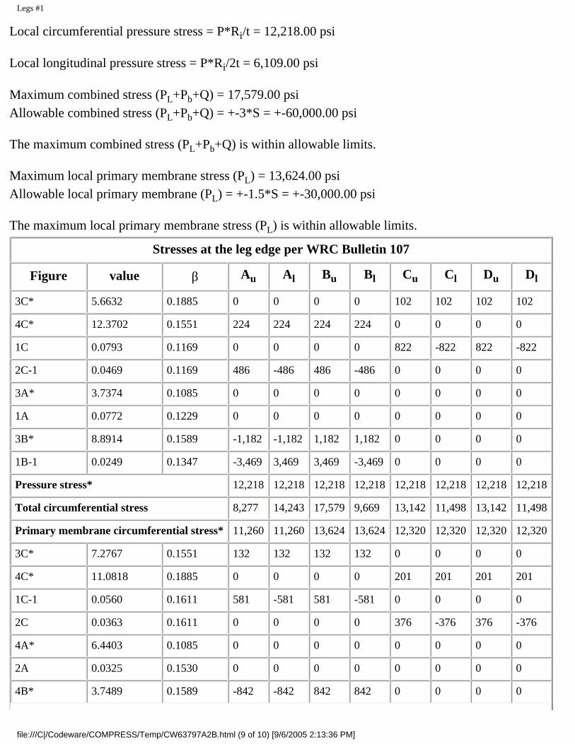
Legs #1
Local circumferential pressure stress = P*Ri/t = 12,218.00 psi
Local longitudinal pressure stress = P*Ri/2t = 6,109.00 psi
Maximum combined stress (PL+Pb+Q) = 17,579.00 psiAllowable combined stress (PL+Pb+Q) = +-3*S = +-60,000.00 psi
The maximum combined stress (PL+Pb+Q) is within allowable limits.
Maximum local primary membrane stress (PL) = 13,624.00 psiAllowable local primary membrane (PL) = +-1.5*S = +-30,000.00 psi
The maximum local primary membrane stress (PL) is within allowable limits.
Stresses at the leg edge per WRC Bulletin 107
Figure value β Au Al Bu Bl Cu Cl Du Dl
3C* 5.6632 0.1885 0 0 0 0 102 102 102 102
4C* 12.3702 0.1551 224 224 224 224 0 0 0 0
1C 0.0793 0.1169 0 0 0 0 822 -822 822 -822
2C-1 0.0469 0.1169 486 -486 486 -486 0 0 0 0
3A* 3.7374 0.1085 0 0 0 0 0 0 0 0
1A 0.0772 0.1229 0 0 0 0 0 0 0 0
3B* 8.8914 0.1589 -1,182 -1,182 1,182 1,182 0 0 0 0
1B-1 0.0249 0.1347 -3,469 3,469 3,469 -3,469 0 0 0 0
Pressure stress* 12,218 12,218 12,218 12,218 12,218 12,218 12,218 12,218
Total circumferential stress 8,277 14,243 17,579 9,669 13,142 11,498 13,142 11,498
Primary membrane circumferential stress* 11,260 11,260 13,624 13,624 12,320 12,320 12,320 12,320
3C* 7.2767 0.1551 132 132 132 132 0 0 0 0
4C* 11.0818 0.1885 0 0 0 0 201 201 201 201
1C-1 0.0560 0.1611 581 -581 581 -581 0 0 0 0
2C 0.0363 0.1611 0 0 0 0 376 -376 376 -376
4A* 6.4403 0.1085 0 0 0 0 0 0 0 0
2A 0.0325 0.1530 0 0 0 0 0 0 0 0
4B* 3.7489 0.1589 -842 -842 842 842 0 0 0 0
file:///C|/Codeware/COMPRESS/Temp/CW63797A2B.html (9 of 10) [9/6/2005 2:13:36 PM]

Legs #1
2B-1 0.0235 0.1753 -2,516 2,516 2,516 -2,516 0 0 0 0
Pressure stress* 6,109 6,109 6,109 6,109 6,109 6,109 6,109 6,109
Total longitudinal stress 3,464 7,334 10,180 3,986 6,686 5,934 6,686 5,934
Primary membrane longitudinal stress* 5,399 5,399 7,083 7,083 6,310 6,310 6,310 6,310
Shear from Mt 0 0 0 0 0 0 0 0
Circ shear from Vc 0 0 0 0 0 0 0 0
Long shear from VL 0 0 0 0 -564 -564 564 564
Total Shear stress 0 0 0 0 -564 -564 564 564
Combined stress (PL+Pb+Q) 8,277 14,243 17,579 9,669 13,191 11,555 13,191 11,555
Note: * denotes primary stress.
file:///C|/Codeware/COMPRESS/Temp/CW63797A2B.html (10 of 10) [9/6/2005 2:13:36 PM]

Seismic Code
Seismic Code
Method of seismic analysis: UBC 1997 ground supported
Seismic Zone: 1
Seismic Zone Factor (Table 16-I): Z = 0.0750
R Factor (Table 16-P): R = 2.2000
Soil profile: (Table 16-Q): SB
Importance Factor: I = 1.0000
Vertical Accelerations Considered: Yes
Force Multiplier: = 0.3333
Minimum Weight Multiplier: = 0.2000
Vessel Characteristics
Vessel height: 13.5625 ft
Vessel Weight:
Operating, Corroded: 37643.6836 lb
Empty, Corroded: 7498.7842 lb
Vacuum, Corroded: 37643.6836 lb
Period of Vibration Calculation
The fundamental period of vibration T (above) is calculated using the Rayleigh method of approximation:
T = 2 * PI * Sqr( {Sum(Wi * yi2 )} / {g * Sum(Wi * yi )} ), where
Wi is the weight of the ith lumped mass, and
yi is its deflection when the system is treated as a cantilever beam.
Fundamental Period, T:
Operating, Corroded: 0.2924 sec (f = 3.4198 Hz)
Empty, Corroded: 0.1281 sec (f = 7.8050 Hz)
Vacuum, Corroded: 0.2924 sec (f = 3.4198 Hz)
Seismic Shear Reports:
Operating, Corroded
file:///C|/Codeware/COMPRESS/Temp/CW36A76DAA.html (1 of 4) [9/6/2005 2:13:36 PM]

Seismic Code
Empty, CorrodedVacuum, Corroded
Base Shear Calculations
Seismic Shear Report: Operating, Corroded
Component Elevation of bottom
above base (in) Elastic modulus E(106 psi)
Inertia I(ft4)
Seismic shear atBottom (lbf)
Bending Moment atBottom (lbf-ft)
Ellipsoidal Head #2 136.50 28.3 * 381.08 385.25
Cylinder #1 (top) 44.50 28.3 8.2476 2,174.08 11,227.06
Legs #1 0.00 29.0 0.0022 2,444.36 19,891.70
Cylinder #1 (bottom) 44.50 28.3 8.2476 264.48 389.09
Ellipsoidal Head #1 44.50 28.3 * 254.64 367.46
*Moment of Inertia I varies over the length of the component
Seismic Shear Report: Empty, Corroded
Component Elevation of bottom
above base (in) Elastic modulus E(106 psi)
Inertia I(ft4)
Seismic shear atBottom (lbf)
Bending Moment atBottom (lbf-ft)
Ellipsoidal Head #2 136.50 29.4 * 167.94 308.31
Cylinder #1 (top) 44.50 29.4 8.2476 413.32 2,680.24
Legs #1 0.00 29.0 0.0022 486.93 4,268.15
Cylinder #1 (bottom) 44.50 29.4 8.2476 68.06 207.51
Ellipsoidal Head #1 44.50 29.4 * 66.72 201.90
*Moment of Inertia I varies over the length of the component
Seismic Shear Report: Vacuum, Corroded
Component Elevation of bottom
above base (in) Elastic modulus E(106 psi)
Inertia I(ft4)
Seismic shear atBottom (lbf)
Bending Moment atBottom (lbf-ft)
Ellipsoidal Head #2 136.50 28.3 * 381.08 385.25
Cylinder #1 (top) 44.50 28.3 8.2476 2,174.08 11,227.06
file:///C|/Codeware/COMPRESS/Temp/CW36A76DAA.html (2 of 4) [9/6/2005 2:13:36 PM]

Seismic Code
Legs #1 0.00 29.0 0.0022 2,444.36 19,891.70
Cylinder #1 (bottom) 44.50 28.3 8.2476 264.48 389.09
Ellipsoidal Head #1 44.50 28.3 * 254.64 367.46
*Moment of Inertia I varies over the length of the component
Base Shear Calculations
Operating, CorrodedEmpty, CorrodedVacuum, Corroded
Base Shear Calculations: Operating, Corroded
Period Determination
Ta = Ct * hn3/4 = 0.02 * (13.5625)3/4 = 0.1413
Cu = 1.4000
The fundamental period T is the lesser of 0.2924 and the value computed below: (0.1979)
Cu * Ta = 1.4000 * 0.1413 = 0.1979
Calculation of Seismic Response Coefficient
V(30-4) = Cv * I * W / (R * T) = 0.0800 * 1.0000 * 37643.6836 / (2.2000 * 0.1979) = 6917.4585
V(30-5) = 2.50 * Ca * I * W / R = 2.50 * 0.0800 * 1.0000 * 37643.6836 / 2.2000 = 3422.1528
V(34-2) = 0.56 * Ca * I * W = 0.56 * 0.0800 * 1.0000 * 37643.6836 = 1686.4370Take the lesser of V(30-4) and V(30-5), and then the greater of this result and V(34-2).Divide this result by 1.4, giving V = 2444.3950 lb
Base Shear Calculations: Empty, Corroded
Period Determination
Ta = Ct * hn3/4 = 0.02 * (13.5625)3/4 = 0.1413
Cu = 1.4000
The fundamental period T is the lesser of 0.1281 and the value computed below: (0.1281)
Cu * Ta = 1.4000 * 0.1413 = 0.1979
file:///C|/Codeware/COMPRESS/Temp/CW36A76DAA.html (3 of 4) [9/6/2005 2:13:36 PM]

Seismic Code
Calculation of Seismic Response Coefficient
V(30-4) = Cv * I * W / (R * T) = 0.0800 * 1.0000 * 7498.7842 / (2.2000 * 0.1281) = 2128.2896
V(30-5) = 2.50 * Ca * I * W / R = 2.50 * 0.0800 * 1.0000 * 7498.7842 / 2.2000 = 681.7076
V(34-2) = 0.56 * Ca * I * W = 0.56 * 0.0800 * 1.0000 * 7498.7842 = 335.9455Take the lesser of V(30-4) and V(30-5), and then the greater of this result and V(34-2).Divide this result by 1.4, giving V = 486.9341 lb
Base Shear Calculations: Vacuum, Corroded
Period Determination
Ta = Ct * hn3/4 = 0.02 * (13.5625)3/4 = 0.1413
Cu = 1.4000
The fundamental period T is the lesser of 0.2924 and the value computed below: (0.1979)
Cu * Ta = 1.4000 * 0.1413 = 0.1979
Calculation of Seismic Response Coefficient
V(30-4) = Cv * I * W / (R * T) = 0.0800 * 1.0000 * 37643.6836 / (2.2000 * 0.1979) = 6917.4585
V(30-5) = 2.50 * Ca * I * W / R = 2.50 * 0.0800 * 1.0000 * 37643.6836 / 2.2000 = 3422.1528
V(34-2) = 0.56 * Ca * I * W = 0.56 * 0.0800 * 1.0000 * 37643.6836 = 1686.4370Take the lesser of V(30-4) and V(30-5), and then the greater of this result and V(34-2).Divide this result by 1.4, giving V = 2444.3950 lb
file:///C|/Codeware/COMPRESS/Temp/CW36A76DAA.html (4 of 4) [9/6/2005 2:13:36 PM]

Liquid Level bounded by Ellipsoidal Head #1
Liquid Level bounded by Ellipsoidal Head #1
Location from datum 100.0000"
Operating Liquid Specific Gravity 1.0000
Test liquid specific gravity 1.0000
file:///C|/Codeware/COMPRESS/Temp/CW2A2DDB49.html [9/6/2005 2:13:37 PM]