counting scalecounting applications. fc-i counting scale: 1/1,000,000 fc-si counting scale: up to...
TRANSCRIPT
ふ
Counting ScaleFC-50Ki FC-5000SiFC-20Ki FC-500SiFC-10KiFC-5000iFC-2000iFC-1000iFC-500i
WM+PD4000541B
This manual and MarksAll safety messages are identified by the following, “WARNING” or “CAUTION”, of ANSIZ535.4 (American National Standard Institute: Product Safety Signs and Labels). Themeanings are as follows:
WARNINGA potentially hazardous situation which, if not avoided, could result indeath or serious injury.
CAUTIONA potentially hazardous situation which, if not avoided, may result inminor or moderate injury.
This is a hazard alert mark.
This mark informs you about the operation of the product.
The information mark of other operations.
Note This manual is subject to change without notice at any time to improve the product. No partof this manual may be photocopied, reproduced, or translated into another languagewithout the prior written consent of the A&D Company.
Product specifications are subject to change without any obligation on the part of themanufacture.
Compliance with FCC rulesPlease note that this equipment generates, uses and can radiate radio frequency energy.This equipment has been tested and has been found to comply with the limits of a Class Acomputing device pursuant to Subpart J of Part 15 of FCC rules. These rules are designedto provide reasonable protection against interference when this equipment is operated in acommercial environment. If this unit is operated in a residential area it might cause someinterference and under these circumstances the user would be required to take, at his ownexpense, whatever measures are necessary to eliminate the interference.(FCC = Federal Communications Commission in the U.S.A.)
Copyright 2003
1©A&D Co.ltd., FC-i Instruction manualInternational version 2279-2A-IE 0305
ContentsContentsContentsContents1. INTRODUCTION............................................................................................................31-1. Introduction..............................................................................................................................31-2. Unpacking................................................................................................................................41-3. Setting Up Your Scale..............................................................................................................51-4. Standby and Operating Mode ..................................................................................................71-5. Simple Operation Mode ...........................................................................................................71-6. kg or lb Weighing Units............................................................................................................71-7. Last Unit Weight Used Feature................................................................................................8
2. FRONT PANEL OVERVIEW..........................................................................................9
3. BASIC OPERATIONS..................................................................................................103-1. Basic Operations ...................................................................................................................103-2. To Start Counting ...................................................................................................................123-3. Unit Weight By Samples ........................................................................................................133-4. Unit Weight By KEYBOARD ..................................................................................................173-5. Unit Weight By ID Number.....................................................................................................18
4. ENTERING A TARE WEIGHT .....................................................................................194-1. Using the KEYBOARD TARE Key .........................................................................................194-2. To Clear TARE .......................................................................................................................20
5. STORE UNIT WEIGHT ................................................................................................215-1. Store Unit Weight by ID Number............................................................................................215-2. Clearing A Stored Unit Weight ...............................................................................................225-3. Store Item Code by ID Number..............................................................................................235-4. Unit Weight, Tare, Comparator Limits & Total Count Stored............................................................25
6. USING THE M+ MEMORY...........................................................................................266-1. The M+ Memory Function......................................................................................................266-2. Viewing the M+ Total..............................................................................................................276-3. Clearing the M+ Total.............................................................................................................276-4. The M- Function.....................................................................................................................27
7. COMPARATOR FUNCTION ........................................................................................28
8. TIME AND DATE FUNCTION......................................................................................30
9. CALIBRATION.............................................................................................................31
2
9-1. Calibration Procedure Using a Weight...................................................................................319-2. Gravity Compensation ...........................................................................................................33
10. F-FUNCTION PARAMETERS....................................................................................3410-1. To Change or View F-Function Settings .............................................................................3410-2. F-Functions ........................................................................................................................36
11. ACAI FUNCTION .......................................................................................................4411-1. ACAI Automatic Counting Accuracy Improvement .........................................................4411-2. ACAI Automatic Operation .................................................................................................4411-3. ACAI Manual Operation .....................................................................................................45
12. RS-232C SERIAL INTERFACE..................................................................................4612-1. RS-232C Specifications......................................................................................................4612-2. Data Output Mode ..............................................................................................................4712-3. Connecting the AD-8121 Printer / MODE 1 or MODE 2 .....................................................4812-4. Connecting the AD-8121 Printer / MODE 3........................................................................4912-5. Command Mode.................................................................................................................5012-6. Using a Bar Code Reader ..................................................................................................5512-7. Using UFC (Universal Flex Coms) Function.......................................................................58
13. OPTIONS ...................................................................................................................6113-1. OP-01 Bar Code Reader ....................................................................................................6113-2. OP-02 Ni-MH Battery Pack ................................................................................................6413-3. OP-03 2 Ch. RS-232C........................................................................................................6613-4. OP-04 RS-232C and Comparator Relay Output ................................................................6713-5. OP-05 Remote Scale Interface ..........................................................................................68
14. SPECIFICATIONS......................................................................................................7214-1. Dimensions.........................................................................................................................74
15. GRAVITY ACCELERATION MAP ..............................................................................75
16. INDEX.........................................................................................................................77
3
1.1.1.1. INTRODUCTIONINTRODUCTIONINTRODUCTIONINTRODUCTION1-1.1-1.1-1.1-1. IntroductionIntroductionIntroductionIntroduction
Thank you for your Purchase!This manual describes the functions of your counting scale and how to get the mostout of it. Read this manual carefully before use.
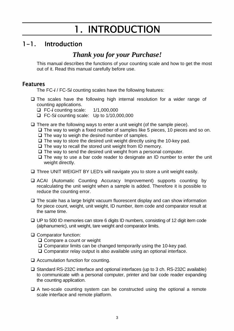
FeaturesFeaturesFeaturesFeaturesThe FC-i / FC-Si counting scales have the following features:
The scales have the following high internal resolution for a wider range ofcounting applications. FC-i counting scale: 1/1,000,000 FC-Si counting scale: Up to 1/10,000,000
There are the following ways to enter a unit weight (of the sample piece). The way to weigh a fixed number of samples like 5 pieces, 10 pieces and so on. The way to weigh the desired number of samples. The way to store the desired unit weight directly using the 10-key pad. The way to recall the stored unit weight from ID memory. The way to send the desired unit weight from a personal computer. The way to use a bar code reader to designate an ID number to enter the unit
weight directly.
Three UNIT WEIGHT BY LED's will navigate you to store a unit weight easily.
ACAI (Automatic Counting Accuracy Improvement) supports counting byrecalculating the unit weight when a sample is added. Therefore it is possible toreduce the counting error.
The scale has a large bright vacuum fluorescent display and can show informationfor piece count, weight, unit weight, ID number, item code and comparator result atthe same time.
UP to 500 ID memories can store 6 digits ID numbers, consisting of 12 digit item code(alphanumeric), unit weight, tare weight and comparator limits.
Comparator function: Compare a count or weight Comparator limits can be changed temporarily using the 10-key pad. Comparator relay output is also available using an optional interface.
Accumulation function for counting.
Standard RS-232C interface and optional interfaces (up to 3 ch. RS-232C available)to communicate with a personal computer, printer and bar code reader expandingthe counting application.
A two-scale counting system can be constructed using the optional a remotescale interface and remote platform.
4
It is possible to send the time and date to a computer connected to the RS-232Cinterface using the scale's built-in clock.
The optional rechargeable battery pack (Ni-MH) is useful for portable operation.
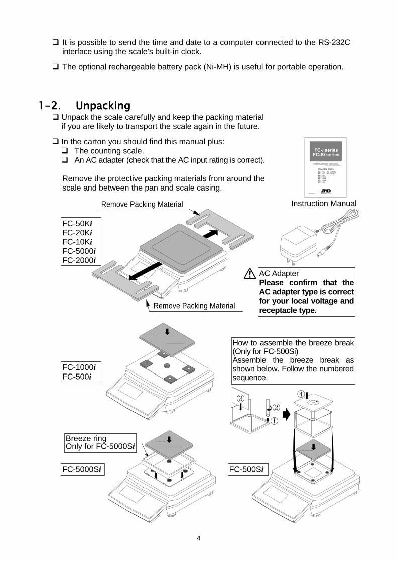
1-2.1-2.1-2.1-2. UnpackingUnpackingUnpackingUnpacking Unpack the scale carefully and keep the packing material
if you are likely to transport the scale again in the future.
In the carton you should find this manual plus: The counting scale. An AC adapter (check that the AC input rating is correct).
Remove the protective packing materials from around thescale and between the pan and scale casing.
Remove Packing Material
Instruction Manual
AC AdapterPlease confirm that theAC adapter type is correctfor your local voltage andreceptacle type.
FC-500Si
FC-1000iFC-500i
FC-50KiFC-20KiFC-10KiFC-5000iFC-2000i
FC-5000Si
Remove Packing Material
Breeze ringOnly for FC-5000Si
How to assemble the breeze break(Only for FC-500Si)Assemble the breeze break asshown below. Follow the numberedsequence.
5
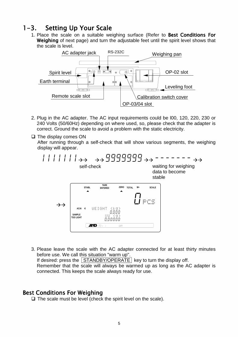
1-3.1-3.1-3.1-3. Setting Up Your ScaleSetting Up Your ScaleSetting Up Your ScaleSetting Up Your Scale1. Place the scale on a suitable weighing surface (Refer to Best Conditions ForBest Conditions ForBest Conditions ForBest Conditions For
WeighingWeighingWeighingWeighing of next page) and turn the adjustable feet until the spirit level shows thatthe scale is level.
2. Plug in the AC adapter. The AC input requirements could be l00, 120, 220, 230 or240 Volts (50/60Hz) depending on where used, so, please check that the adapter iscorrect. Ground the scale to avoid a problem with the static electricity.
The display comes ONAfter running through a self-check that will show various segments, the weighingdisplay will appear.
1111111 9999999 -------
self-check
3. Please leave the scale with the AC adapter connected for at least thirty minutesbefore use. We call this situation "warm up".If desired: press the STANDBY/OPERATE key to turn the display off.Remember that the scale will always be warmed up as long as the AC adapter isconnected. This keeps the scale always ready for use.
Best Conditions Best Conditions Best Conditions Best Conditions For WeighingFor WeighingFor WeighingFor Weighing The scale must be level (check the spirit level on the scale).
waiting for weighingdata to becomestable
STABL
8888880
12134567890 .000
123145670 .00000
ZERO TOTAL M+TARE
ENTERED SCALE
ACAI
SAMPLETOO LIGHT
Spirit level
Leveling footEarth terminal
Weighing pan
Remote scale slot
AC adapter jack
OP-02 slot
OP-03/04 slotCalibration switch cover
RS-232C
6
Best operating temperature is between 20°C~25°C / 68°F~77°F at about 50%~60%relative humidity. There shouldn’t be large temperature fluctuations.
The weighing room should be kept clean and dry.
The weighing table must be of a solid construction.
Corners of rooms are best as they are less prone to vibrations.
Don’t install the scale near heaters or air conditioners.
Don’t install the scale in direct sunshine.
Try to ensure a stable AC power supply when using the AC adapter.
Keep equipment containing magnets away from the scale.
Warm up the scale before use or leave it on standby overnight.
Ground the scale chassis for electrostatic discharge if the weighing conditions warrant.
CalibrationCalibrationCalibrationCalibrationCalibration of the scale is required when the scale is initially installed, or if a remotescale is added. Please refer to “9.... CALIBRATION CALIBRATION CALIBRATION CALIBRATION” for more calibration information.
7
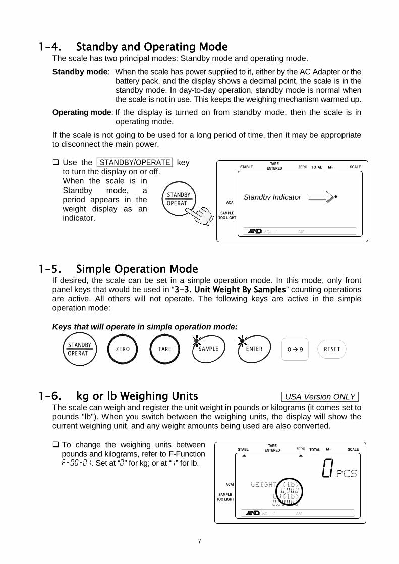
1-4.1-4.1-4.1-4. Standby and Operating ModeStandby and Operating ModeStandby and Operating ModeStandby and Operating ModeThe scale has two principal modes: Standby mode and operating mode.Standby mode: When the scale has power supplied to it, either by the AC Adapter or the
battery pack, and the display shows a decimal point, the scale is in thestandby mode. In day-to-day operation, standby mode is normal whenthe scale is not in use. This keeps the weighing mechanism warmed up.
Operating mode: If the display is turned on from standby mode, then the scale is inoperating mode.
If the scale is not going to be used for a long period of time, then it may be appropriateto disconnect the main power.
Use the STANDBY/OPERATE keyto turn the display on or off.When the scale is inStandby mode, aperiod appears in theweight display as anindicator.
1-5.1-5.1-5.1-5. Simple Operation ModeSimple Operation ModeSimple Operation ModeSimple Operation ModeIf desired, the scale can be set in a simple operation mode. In this mode, only frontpanel keys that would be used in “3-33-33-33-3. Unit Weight By Samples. Unit Weight By Samples. Unit Weight By Samples. Unit Weight By Samples” counting operationsare active. All others will not operate. The following keys are active in the simpleoperation mode:
Keys that will operate in simple operation mode:
1-6.1-6.1-6.1-6. kg or lb Weighing Unitskg or lb Weighing Unitskg or lb Weighing Unitskg or lb Weighing UnitsThe scale can weigh and register the unit weight in pounds or kilograms (it comes set topounds "lb"). When you switch between the weighing units, the display will show thecurrent weighing unit, and any weight amounts being used are also converted.
To change the weighing units betweenpounds and kilograms, refer to F-Functionf-00-01. Set at “0” for kg; or at “1” for lb.
STABL
8888880
11234567890 .000
123145670 .00000
ZERO TOTAL M+TARE
ENTERED SCALE
ACAI
SAMPLETOO LIGHT
OPERATSTANDBY ZERO TARE SAMPLE ENTER RESET0 9
USA Version ONLY
OPERATSTANDBY
STABLE
888888 .
123456789012345678901234567
123456789012345678901234567
ZERO TOTAL M+TARE
ENTERED SCALE
ACAI
SAMPLETOO LIGHT
Standby Indicator
8
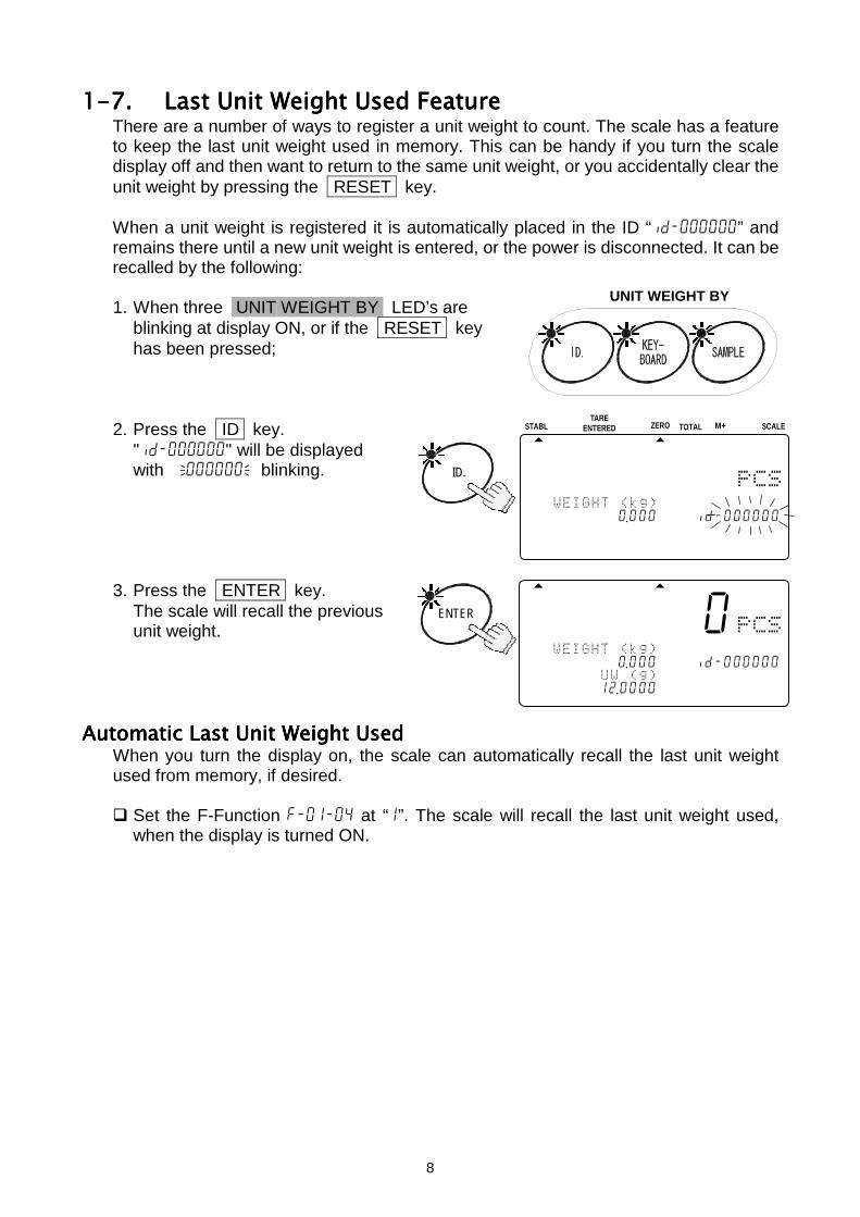
1-7.1-7.1-7.1-7. Last Unit Weight Used FeatureLast Unit Weight Used FeatureLast Unit Weight Used FeatureLast Unit Weight Used FeatureThere are a number of ways to register a unit weight to count. The scale has a featureto keep the last unit weight used in memory. This can be handy if you turn the scaledisplay off and then want to return to the same unit weight, or you accidentally clear theunit weight by pressing the RESET key.
When a unit weight is registered it is automatically placed in the ID “id-000000” andremains there until a new unit weight is entered, or the power is disconnected. It can berecalled by the following:
1. When three UNIT WEIGHT BY LED’s areblinking at display ON, or if the RESET keyhas been pressed;
2. Press the ID key."id-000000" will be displayedwith 000000blinking.
3. Press the ENTER key.The scale will recall the previousunit weight.
Automatic Last Unit Weight UsedAutomatic Last Unit Weight UsedAutomatic Last Unit Weight UsedAutomatic Last Unit Weight UsedWhen you turn the display on, the scale can automatically recall the last unit weightused from memory, if desired.
Set the F-Function f-01-04 at “1”. The scale will recall the last unit weight used,when the display is turned ON.
ID.
STABL
8888810
12345617890 .0004578id-000000
12345670 .00000
ZERO TOTAL M+TARE
ENTERED SCALE
------0
1234516---0 .0004568id-000000
1234561712 .0000
ENTER
UNIT WEIGHT BY
9
2.2.2. 2. FRONT PANEL OVERVIEWFRONT PANEL OVERVIEWFRONT PANEL OVERVIEWFRONT PANEL OVERVIEW
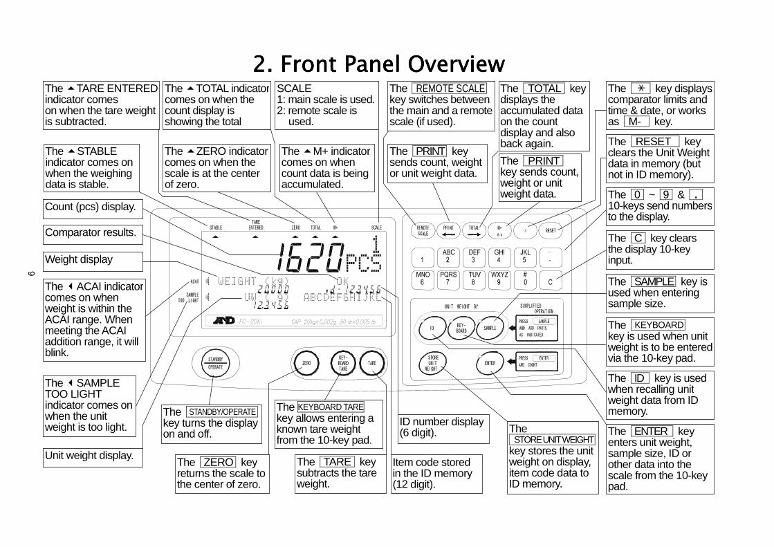
2. Front Panel Overview2. Front Panel Overview2. Front Panel Overview2. Front Panel OverviewThe key displayscomparator limits andtime & date, or worksas M- key.
The TARE ENTEREDindicator comeson when the tare weightis subtracted.
The STABLEindicator comes onwhen the weighingdata is stable.
Count (pcs) display.
Comparator results.
The ACAI indicatorcomes on whenweight is within theACAI range. Whenmeeting the ACAIaddition range, it willblink.
The SAMPLETOO LIGHTindicator comes onwhen the unitweight is too light.
Unit weight display.
The TOTAL indicatorcomes on when thecount display isshowing the total
The ZERO indicatorcomes on when thescale is at the centerof zero.
The STANDBY/OPERATEkey turns the displayon and off.
The ZERO keyreturns the scale tothe center of zero.
SCALE1: main scale is used.2: remote scale is__used.
The M+ indicatorcomes on whencount data is beingaccumulated.
The REMOTE SCALEkey switches betweenthe main and a remotescale (if used).
The PRINT keysends count, weightor unit weight data.
The KEYBOARD TAREkey allows entering aknown tare weightfrom the 10-key pad.
The TARE keysubtracts the tareweight.
ID number display(6 digit).
Item code storedin the ID memory(12 digit).
The TOTAL keydisplays theaccumulated dataon the countdisplay and alsoback again.The PRINTkey sends count,weight or unitweight data.
The STORE UNIT WEIGHTkey stores the unitweight on display,item code data toID memory.
The RESET keyclears the Unit Weightdata in memory (butnot in ID memory).
The 0 ~ 9 & . 10-keys send numbersto the display.
The C key clearsthe display 10-keyinput.
The SAMPLE key isused when enteringsample size.
The KEYBOARDkey is used when unitweight is to be enteredvia the 10-key pad.
The ID key is usedwhen recalling unitweight data from IDmemory.
The ENTER keyenters unit weight,sample size, ID orother data into thescale from the 10-keypad.
Weight display
10
3.3.3.3. BASIC OPERATIONSBASIC OPERATIONSBASIC OPERATIONSBASIC OPERATIONS3-1.3-1.3-1.3-1. Basic OperationsBasic OperationsBasic OperationsBasic OperationsTurn The Display ON and OFFTurn The Display ON and OFFTurn The Display ON and OFFTurn The Display ON and OFF
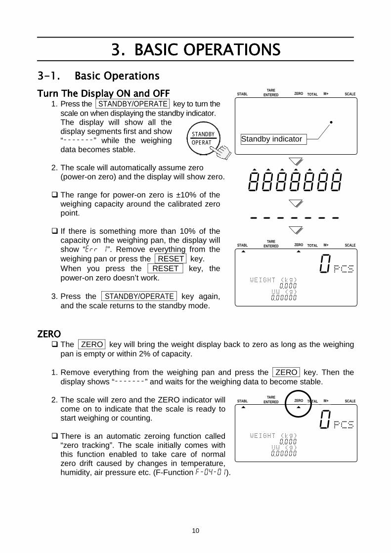
1. Press the STANDBY/OPERATE key to turn thescale on when displaying the standby indicator.The display will show all thedisplay segments first and show“-------” while the weighingdata becomes stable.
2. The scale will automatically assume zero(power-on zero) and the display will show zero.
The range for power-on zero is ±10% of theweighing capacity around the calibrated zeropoint.
If there is something more than 10% of thecapacity on the weighing pan, the display willshow “err 1”. Remove everything from theweighing pan or press the RESET key.When you press the RESET key, thepower-on zero doesn’t work.
3. Press the STANDBY/OPERATE key again,and the scale returns to the standby mode.
ZEROZEROZEROZERO The ZERO key will bring the weight display back to zero as long as the weighing
pan is empty or within 2% of capacity.
1. Remove everything from the weighing pan and press the ZERO key. Then thedisplay shows “-------” and waits for the weighing data to become stable.
2. The scale will zero and the ZERO indicator willcome on to indicate that the scale is ready tostart weighing or counting.
There is an automatic zeroing function called“zero tracking”. The scale initially comes withthis function enabled to take care of normalzero drift caused by changes in temperature,humidity, air pressure etc. (F-Function f-04-01).
STABL
8888810
12345167890 .000
123415670 .0000045678901234567
ZERO TOTAL M+TARE
ENTERED SCALE
STABL
8888888.
888888888888888888888888888
888888888888888888888888888
ZERO TOTAL M+TARE
ENTERED SCALE
OPERATSTANDBY
STABL
8888810
12134567890 .000
123415670 .00000
ZERO TOTAL M+TARE
ENTERED SCALE
8888888
-------
Standby indicator
11
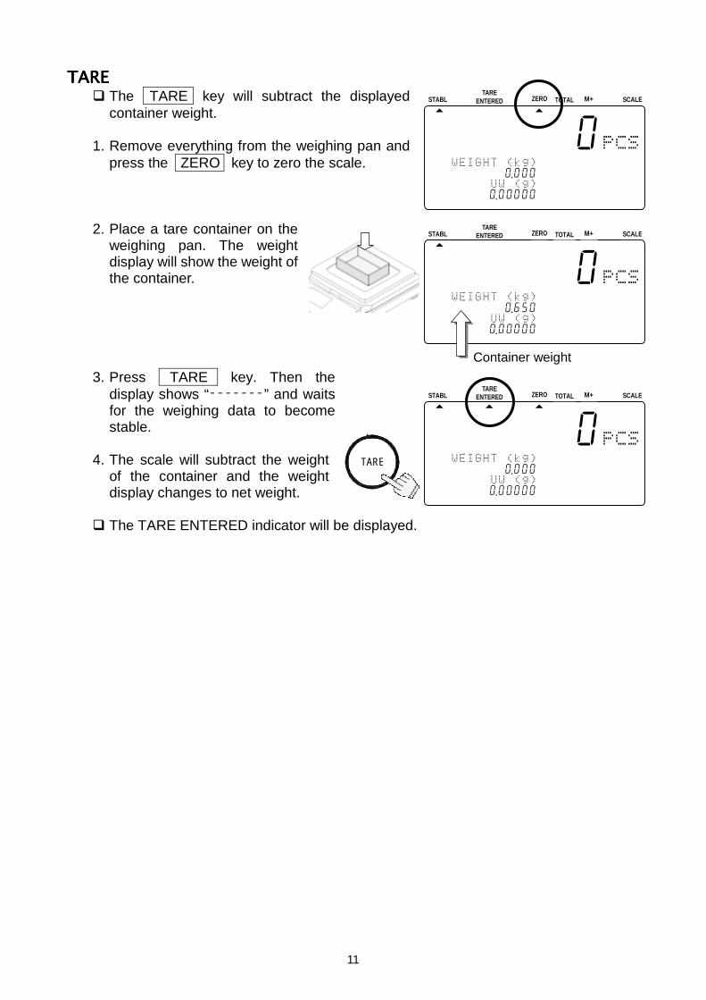
TARETARETARETARE The TARE key will subtract the displayed
container weight.
1. Remove everything from the weighing pan andpress the ZERO key to zero the scale.
2. Place a tare container on theweighing pan. The weightdisplay will show the weight ofthe container.
3. Press TARE key. Then thedisplay shows “-------” and waitsfor the weighing data to becomestable.
4. The scale will subtract the weightof the container and the weightdisplay changes to net weight.
The TARE ENTERED indicator will be displayed.
STABL
8888810
12134567890 .000
123415670 .0000045678901234567
ZERO TOTAL M+TARE
ENTERED SCALE
STABL
8888810
12314567890 .650
123451670 .00000
ZERO TOTAL M+TARE
ENTERED SCALE
Container weight
STABL
8888810
12134567890 .000
123415670 .0000045678901234567
ZERO TOTAL M+TARE
ENTERED SCALE
TARE
12
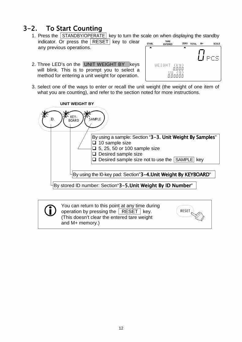
3-2.3-2.3-2.3-2. To Start CountingTo Start CountingTo Start CountingTo Start Counting1. Press the STANDBY/OPERATE key to turn the scale on when displaying the standby
indicator. Or press the RESET key to clearany previous operations.
2. Three LED’s on the UNIT WEIGHT BY keyswill blink. This is to prompt you to select amethod for entering a unit weight for operation.
3. Select one of the ways to enter or recall the unit weight (the weight of one item ofwhat you are counting), and refer to the section noted for more instructions.
STABL
8888810
12134567890 .000
123415670 .0000045678901234567
ZERO TOTAL M+TARE
ENTERED SCALE
You can return to this point at any time duringoperation by pressing the RESET key.(This doesn’t clear the entered tare weightand M+ memory.)
RESET
KEY-BOARD SAMPLEID.
UNIT WEIGHT BY
By using a sample: Section “3-3. 3-3. 3-3. 3-3. Unit Weight By SamplesUnit Weight By SamplesUnit Weight By SamplesUnit Weight By Samples” 10 sample size 5, 25, 50 or 100 sample size Desired sample size Desired sample size not to use the SAMPLE key
By using the l0-key pad: Section“3-43-43-43-4.Unit Weight By KEYBOARD.Unit Weight By KEYBOARD.Unit Weight By KEYBOARD.Unit Weight By KEYBOARD”
By stored lD number: Section“3-53-53-53-5.Unit Weight By ID Number.Unit Weight By ID Number.Unit Weight By ID Number.Unit Weight By ID Number”
13
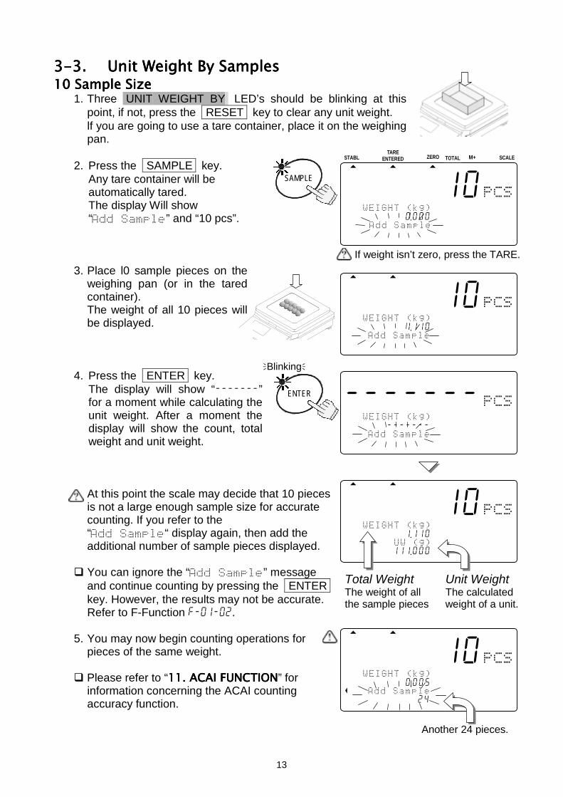
3-3.3-3.3-3.3-3. Unit Weight By SamplesUnit Weight By SamplesUnit Weight By SamplesUnit Weight By Samples10 Sample Size10 Sample Size10 Sample Size10 Sample Size
1. Three UNIT WEIGHT BY LED’s should be blinking at thispoint, if not, press the RESET key to clear any unit weight.lf you are going to use a tare container, place it on the weighingpan.
2. Press the SAMPLE key.Any tare container will beautomatically tared.The display Will show“” and “10 pcs”.
3. Place l0 sample pieces on theweighing pan (or in the taredcontainer).The weight of all 10 pieces willbe displayed.
4. Press the ENTER key.The display will show “-------”for a moment while calculating theunit weight. After a moment thedisplay will show the count, totalweight and unit weight.
At this point the scale may decide that 10 piecesis not a large enough sample size for accuratecounting. If you refer to the““ display again, then add theadditional number of sample pieces displayed.
You can ignore the “” messageand continue counting by pressing the ENTERkey. However, the results may not be accurate.Refer to F-Function f-01-02.
5. You may now begin counting operations forpieces of the same weight.
Please refer to “11111111. ACAI FUNCTION. ACAI FUNCTION. ACAI FUNCTION. ACAI FUNCTION” forinformation concerning the ACAI countingaccuracy function.
Another 24 pieces.
If weight isn’t zero, press the TARE.
8888810
12134567891 .110
12341567111 .000
Total Weight Unit WeightThe weight of all The calculatedthe sample pieces weight of a unit.
SAMPLE
STABL
8888810
12134567890 .000
123456789012345678901234567
ZERO TOTAL M+TARE
ENTERED SCALE
8888810
1234567 891 .110A 123456789012345678901234567
Blinking
-------
1123456-------A 123456789012345678901234567
ENTER
8888810
12134567890 .005A 12134567890124
14
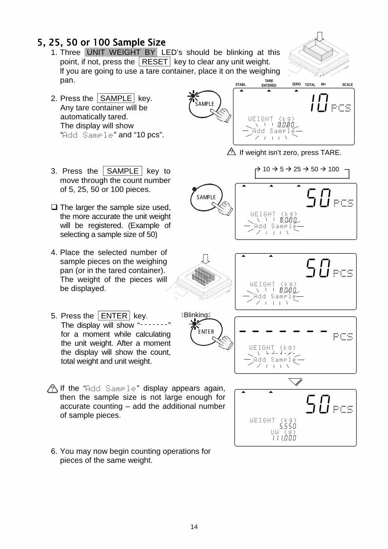
5, 25, 50 or 100 Sample Size5, 25, 50 or 100 Sample Size5, 25, 50 or 100 Sample Size5, 25, 50 or 100 Sample Size1. Three UNIT WEIGHT BY LED’s should be blinking at this
point, if not, press the RESET key to clear any unit weight.lf you are going to use a tare container, place it on the weighingpan.
2. Press the SAMPLE key.Any tare container will beautomatically tared.The display will show“” and “10 pcs”.
3. Press the SAMPLE key tomove through the count numberof 5, 25, 50 or 100 pieces.
The larger the sample size used,the more accurate the unit weightwill be registered. (Example ofselecting a sample size of 50)
4. Place the selected number ofsample pieces on the weighingpan (or in the tared container).The weight of the pieces willbe displayed.
5. Press the ENTER key.The display will show “-------”for a moment while calculatingthe unit weight. After a momentthe display will show the count,total weight and unit weight.
If the “” display appears again,then the sample size is not large enough foraccurate counting – add the additional numberof sample pieces.
6. You may now begin counting operations forpieces of the same weight.
8888850
11234567895 .550A 12341567111 .000
Blinking
SAMPLE
STABL
8888810
12134567890 .000
123456789012345678901234567
ZERO TOTAL M+TARE
ENTERED SCALE
10 5 25 50 100
SAMPLE
8888850
11234567890 .000A 123456789012345678901234567
-------
A1213456-------A 123456789012345678901234567
ENTER
8888850
11234567890 .000A 123456789012345678901234567
If weight isn’t zero, press TARE.
15
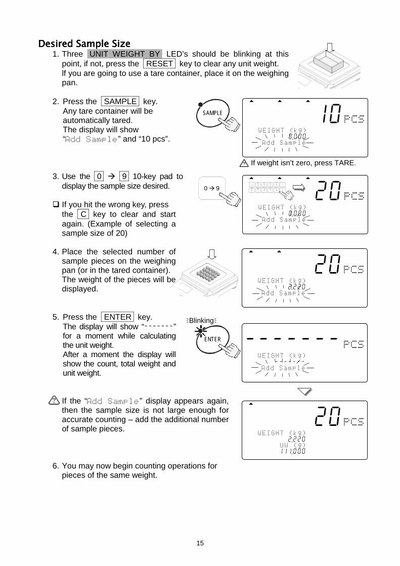
Desired Sample SizeDesired Sample SizeDesired Sample SizeDesired Sample Size1. Three UNIT WEIGHT BY LED’s should be blinking at this
point, if not, press the RESET key to clear any unit weight.lf you are going to use a tare container, place it on the weighingpan.
2. Press the SAMPLE key.Any tare container will beautomatically tared.The display will show“” and “10 pcs”.
3. Use the 0 9 10-key pad todisplay the sample size desired.
If you hit the wrong key, pressthe C key to clear and startagain. (Example of selecting asample size of 20)
4. Place the selected number ofsample pieces on the weighingpan (or in the tared container).The weight of the pieces will bedisplayed.
5. Press the ENTER key.The display will show “-------”for a moment while calculatingthe unit weight.After a moment the display willshow the count, total weight andunit weight.
If the “” display appears again,then the sample size is not large enough foraccurate counting – add the additional numberof sample pieces.
6. You may now begin counting operations forpieces of the same weight.
8888820
12134567892 .220
12314567111 .000
Blinking
0 9
8888820
11234567890 .000A 123456789012345678901234567
TUV
DEFABC
MNO
6
1
7 8PQRS
2 3JKLGHI
09WXYZ
4
#
5
C
.
8888820
11234567892 .220A 123456789012345678901234567
SAMPLE
8888810
11234567890 .000A 12345678901234567
-------
1213456-------A 123456789012345678901234567
ENTER
If weight isn’t zero, press TARE.
16
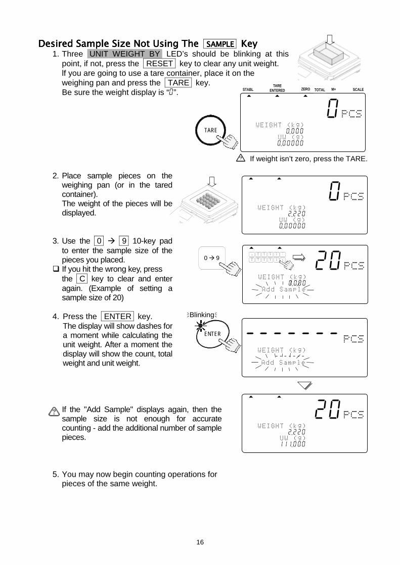
Desired Sample Size Not Using Desired Sample Size Not Using Desired Sample Size Not Using Desired Sample Size Not Using The The The The SAMPLESAMPLESAMPLESAMPLE Key Key Key Key1. Three UNIT WEIGHT BY LED’s should be blinking at this
point, if not, press the RESET key to clear any unit weight.lf you are going to use a tare container, place it on theweighing pan and press the TARE key.Be sure the weight display is “0”.
2. Place sample pieces on theweighing pan (or in the taredcontainer).The weight of the pieces will bedisplayed.
3. Use the 0 9 10-key padto enter the sample size of thepieces you placed.
If you hit the wrong key, pressthe C key to clear and enteragain. (Example of setting asample size of 20)
4. Press the ENTER key.The display will show dashes fora moment while calculating theunit weight. After a moment thedisplay will show the count, totalweight and unit weight.
If the "Add Sample" displays again, then thesample size is not enough for accuratecounting - add the additional number of samplepieces.
5. You may now begin counting operations forpieces of the same weight.
8888820
11234567892 .220
12345167111 .000
8888820
11234567892 .220A 121345670 .00000
STABL
8888810
12134567890 .000
123415670 .0000045678901234567
ZERO TOTAL M+TARE
ENTERED SCALE
Blinking
If weight isn’t zero, press the TARE.
0 9
8888820
11234567890 .000A 123456789012345678901234567
TUV
DEFABC
MNO
6
1
7 8PQRS
2 3JKLGHI
09WXYZ
4
#
5
C
.
-------
1213456-------A 123456789012345678901234567
ENTER
TARE
17
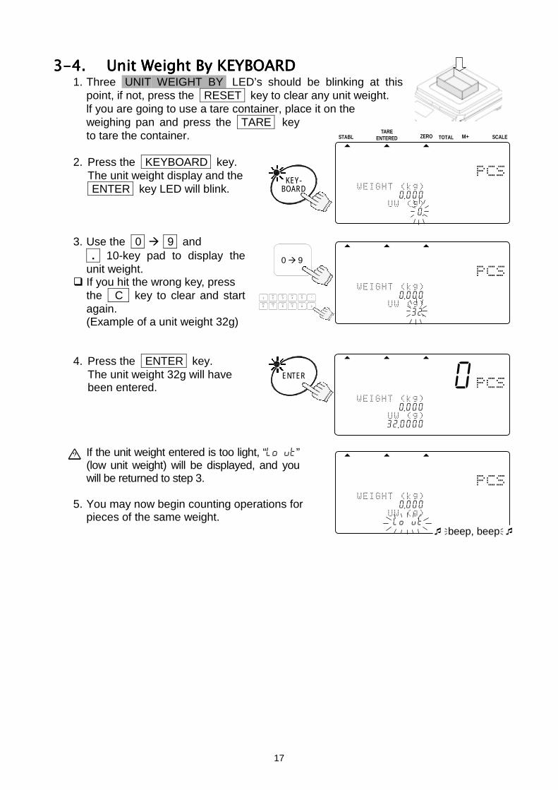
3-4.3-4.3-4.3-4. Unit Weight By KEYBOARDUnit Weight By KEYBOARDUnit Weight By KEYBOARDUnit Weight By KEYBOARD1. Three UNIT WEIGHT BY LED’s should be blinking at this
point, if not, press the RESET key to clear any unit weight.lf you are going to use a tare container, place it on theweighing pan and press the TARE keyto tare the container.
2. Press the KEYBOARD key.The unit weight display and the ENTER key LED will blink.
3. Use the 0 9 and . 10-key pad to display theunit weight.
If you hit the wrong key, pressthe C key to clear and startagain.(Example of a unit weight 32g)
4. Press the ENTER key.The unit weight 32g will havebeen entered.
If the unit weight entered is too light, “lo ut”(low unit weight) will be displayed, and youwill be returned to step 3.
5. You may now begin counting operations forpieces of the same weight.
KEY-BOARD
STABL
8888810
11234567890 .000
12314567890120 .45678901234567
ZERO TOTAL M+TARE
ENTERED SCALE
------0
1213456---0 .000
1234156732 .0000
ENTER
------0
123456-0--0 .000
12314567llo utbeep, beep
0 9
8888850
12134567890 .000
12341567890132 .45678901234567
TUV
DEFABC
MNO
6
1
7 8PQRS
2 3JKLGHI
09WXYZ
4
#
5
C
.
18
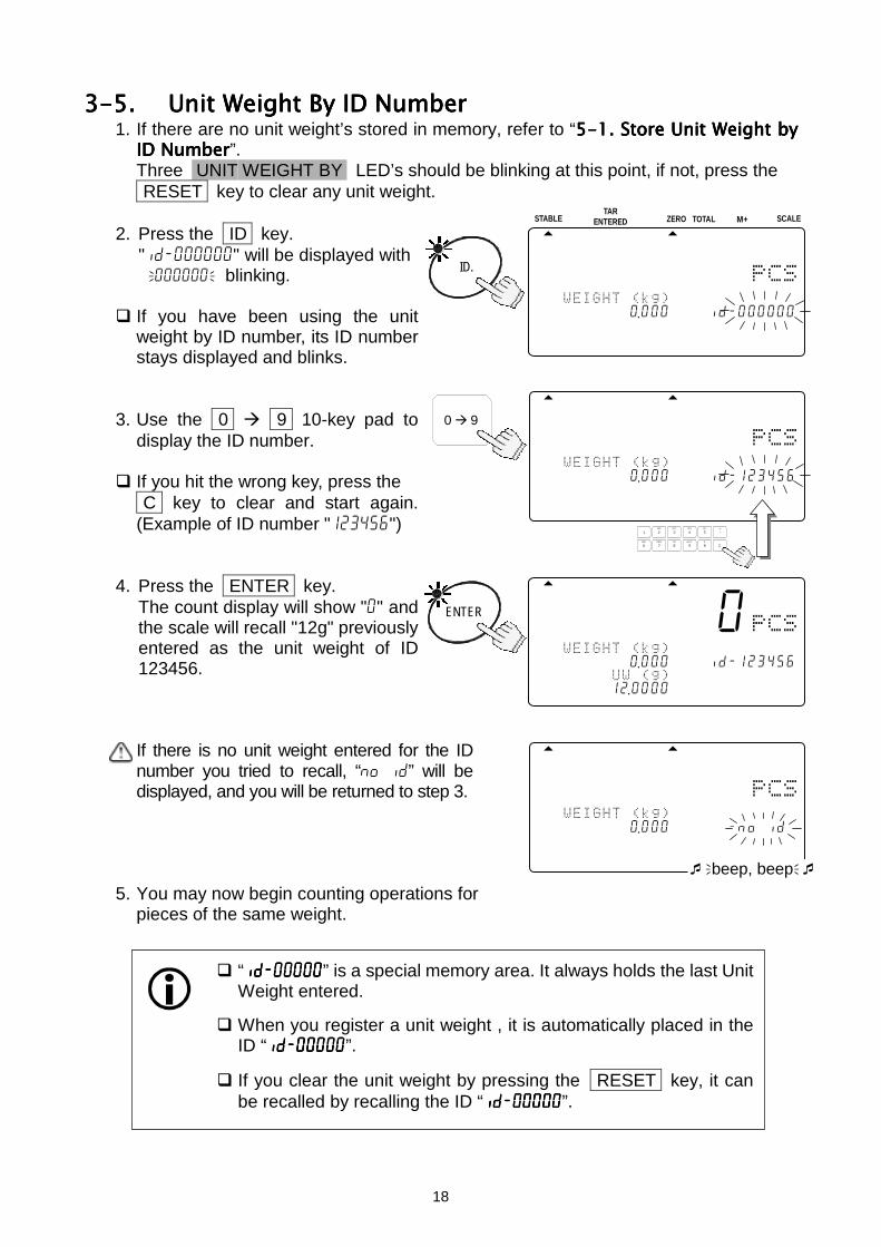
3-5.3-5.3-5.3-5. Unit Weight By ID NumberUnit Weight By ID NumberUnit Weight By ID NumberUnit Weight By ID Number1. If there are no unit weight’s stored in memory, refer to “5-15-15-15-1. Store Unit Weight by. Store Unit Weight by. Store Unit Weight by. Store Unit Weight by
ID NumberID NumberID NumberID Number”.Three UNIT WEIGHT BY LED’s should be blinking at this point, if not, press the RESET key to clear any unit weight.
2. Press the ID key."id-000000" will be displayed with000000blinking.
If you have been using the unitweight by ID number, its ID numberstays displayed and blinks.
3. Use the 0 9 10-key pad todisplay the ID number.
If you hit the wrong key, press the C key to clear and start again.(Example of ID number "123456")
4. Press the ENTER key.The count display will show "0" andthe scale will recall "12g" previouslyentered as the unit weight of ID123456.
If there is no unit weight entered for the IDnumber you tried to recall, “no id” will bedisplayed, and you will be returned to step 3.
5. You may now begin counting operations forpieces of the same weight.
------0
1234561---0 .0004568id-123456
1234561712 .0000
ENTER
------0
1234561---0 .0004568id-no id
1234567l0 .0000beep, beep
ID.
STABLE
8888810
12345167890 .0004578id-000000
12345670 .00000
ZERO TOTAL M+TAR
ENTERED SCALE
0 9
8888850
12134561890 .0004578id-123456
123415610 .00000
TUV
DEFABC
MNO
6
1
7 8PQRS
2 3JKLGHI
09WXYZ
4
#
5
C
.
“id-00000id-00000id-00000id-00000” is a special memory area. It always holds the last UnitWeight entered.
When you register a unit weight , it is automatically placed in theID “id-00000id-00000id-00000id-00000”.
If you clear the unit weight by pressing the RESET key, it canbe recalled by recalling the ID “id-00000id-00000id-00000id-00000”.
19
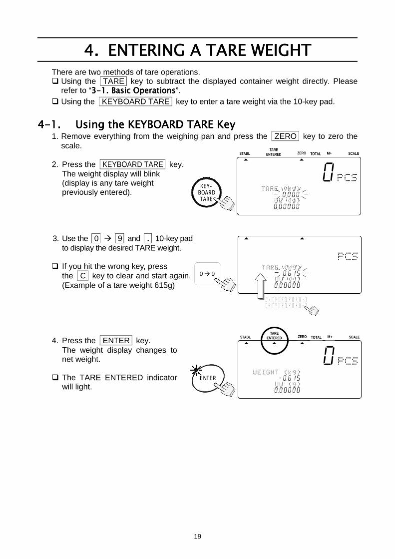
4.4.4.4. ENTERING A TARE WEIGHTENTERING A TARE WEIGHTENTERING A TARE WEIGHTENTERING A TARE WEIGHTThere are two methods of tare operations. Using the TARE key to subtract the displayed container weight directly. Please
refer to “3-13-13-13-1. Basic Operations. Basic Operations. Basic Operations. Basic Operations”. Using the KEYBOARD TARE key to enter a tare weight via the 10-key pad.
4-1.4-1.4-1.4-1. Using the KEYBOARD TARE KeyUsing the KEYBOARD TARE KeyUsing the KEYBOARD TARE KeyUsing the KEYBOARD TARE Key1. Remove everything from the weighing pan and press the ZERO key to zero the
scale.
2. Press the KEYBOARD TARE key.The weight display will blink(display is any tare weightpreviously entered).
3. Use the 0 9 and . 10-key padto display the desired TARE weight.
If you hit the wrong key, pressthe C key to clear and start again.(Example of a tare weight 615g)
4. Press the ENTER key.The weight display changes tonet weight.
The TARE ENTERED indicatorwill light.
STABL
8888810
121345678-0 .615
123415670 .0000045678901234567
ZERO TOTAL M+TARE
ENTERED SCALE
0 9
STABL
8888810
12314567890 .000
123451670 .0000045678901234567
ZERO TOTAL M+TARE
ENTERED SCALE
8888850
12314567890 .615
123451670 .00000
TUV
DEFABC
MNO
6
1
7 8PQRS
2 3JKLGHI
09WXYZ
4
#
5
C
.
ENTER
TARE
KEY-BOARD
20
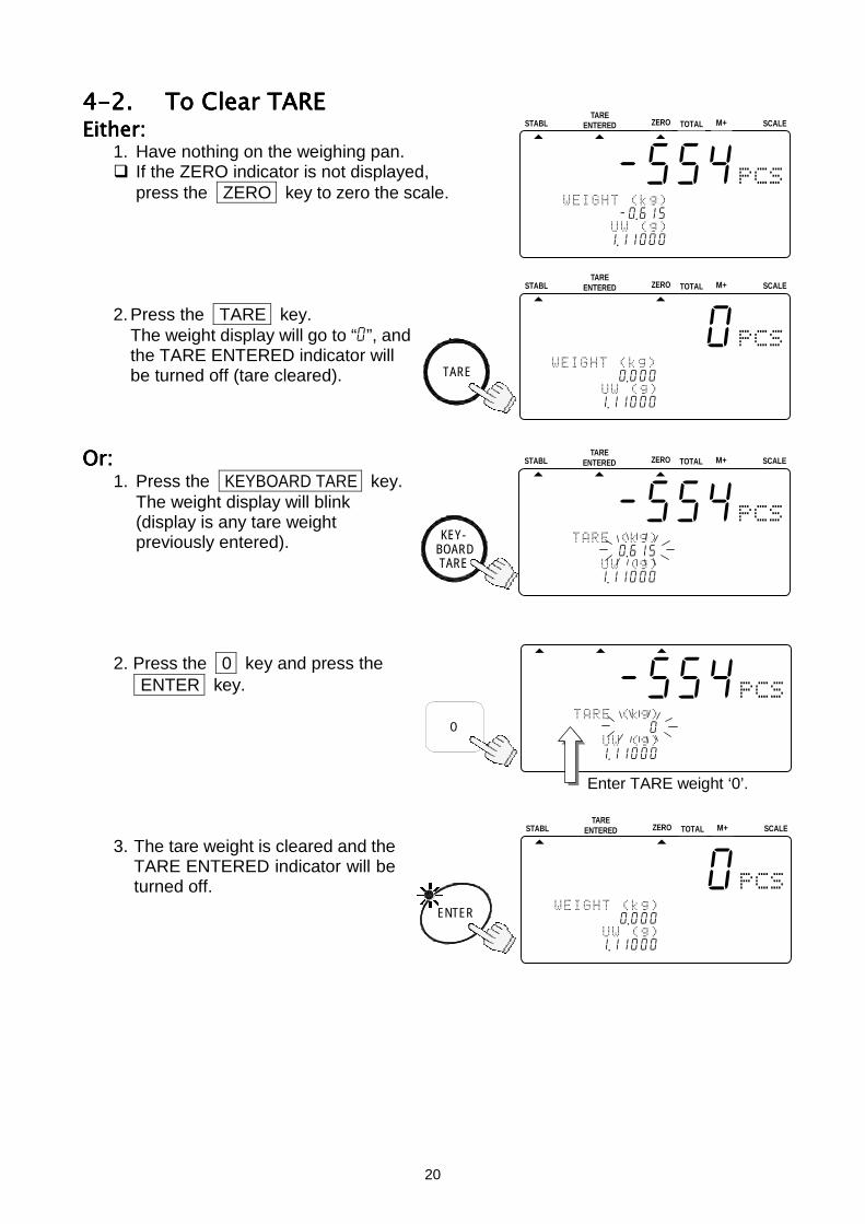
4-2.4-2.4-2.4-2. To Clear TARETo Clear TARETo Clear TARETo Clear TAREEither:Either:Either:Either:
1. Have nothing on the weighing pan. If the ZERO indicator is not displayed,
press the ZERO key to zero the scale.
2. Press the TARE key.The weight display will go to “0”, andthe TARE ENTERED indicator willbe turned off (tare cleared).
Or:Or:Or:Or:1. Press the KEYBOARD TARE key.
The weight display will blink(display is any tare weightpreviously entered).
2. Press the 0 key and press the ENTER key.
3. The tare weight is cleared and theTARE ENTERED indicator will beturned off.
STABL
888-554
1234105678-0 .615
1234151671 .1100045678901234567
ZERO TOTAL M+TARE
ENTERED SCALE
STABL
888-510
A12134567890 .000
123456171 .1100045678901234567
ZERO TOTAL M+TARE
ENTERED SCALE
TARE
STABL
8888810
123415678-0 .000
123456171 .1100045678901234567
ZERO TOTAL M+TARE
ENTERED SCALE
0
TARE
KEY-BOARD
STABL
888-554
12341567890 .615
123456171 .1100045678901234567
ZERO TOTAL M+TARE
ENTERED SCALE
ENTER
888-554
12314567890 .000
123451671 .11000
Enter TARE weight ‘0’.
21
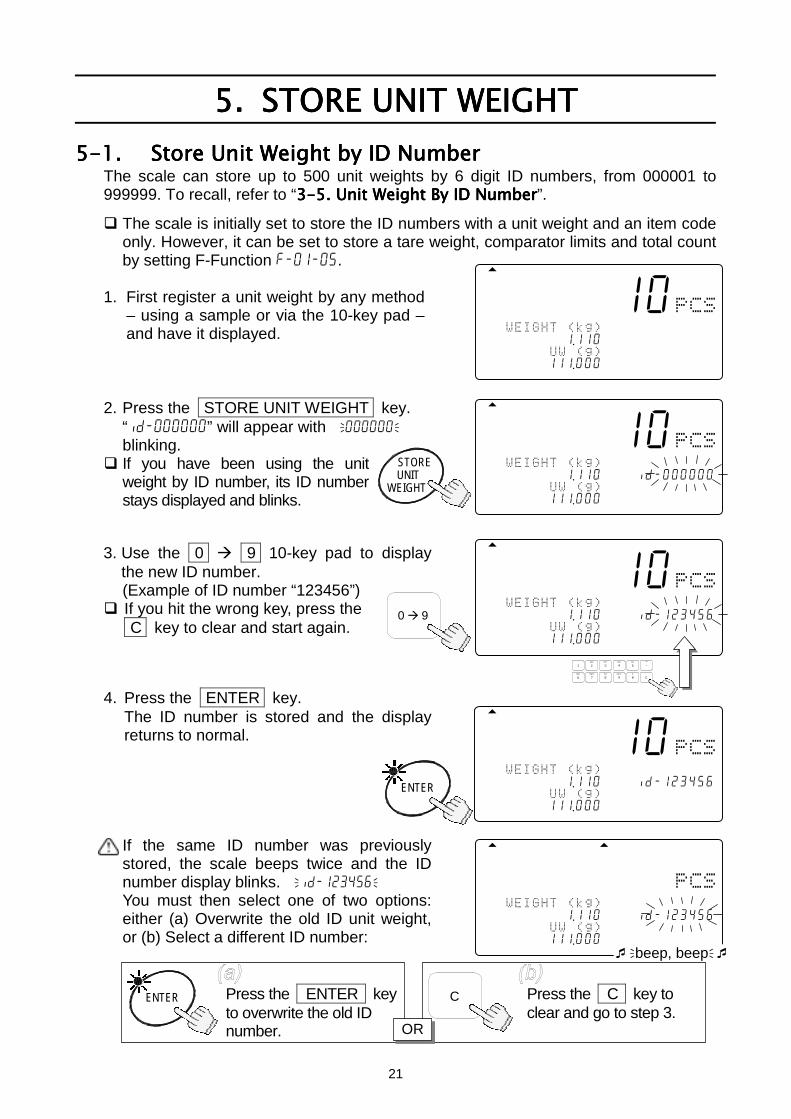
5.5.5.5. STORE UNIT WEIGHTSTORE UNIT WEIGHTSTORE UNIT WEIGHTSTORE UNIT WEIGHT5-1.5-1.5-1.5-1. Store Unit Weight by ID NumberStore Unit Weight by ID NumberStore Unit Weight by ID NumberStore Unit Weight by ID Number
The scale can store up to 500 unit weights by 6 digit ID numbers, from 000001 to999999. To recall, refer to “3-53-53-53-5. Unit Weight By ID Number. Unit Weight By ID Number. Unit Weight By ID Number. Unit Weight By ID Number”. The scale is initially set to store the ID numbers with a unit weight and an item code
only. However, it can be set to store a tare weight, comparator limits and total countby setting F-Function f-01-05.
1. First register a unit weight by any method– using a sample or via the 10-key pad –and have it displayed.
2. Press the STORE UNIT WEIGHT key.“id-000000” will appear with 000000blinking.
If you have been using the unitweight by ID number, its ID numberstays displayed and blinks.
3. Use the 0 9 10-key pad to displaythe new ID number.(Example of ID number “123456”)
If you hit the wrong key, press the C key to clear and start again.
4. Press the ENTER key.The ID number is stored and the displayreturns to normal.
If the same ID number was previouslystored, the scale beeps twice and the IDnumber display blinks. id-123456You must then select one of two options:either (a) Overwrite the old ID unit weight,or (b) Select a different ID number:
Press the ENTER keyto overwrite the old IDnumber.
ENTER Press the C key toclear and go to step 3.
C
OR
888-510
12345167891 .110
12345671111 .000
8888810
12304567891 .1104578id-000000
12345671111 .000
STORE
WEIGHTUNIT
0 9
8888810
12345671891 .1104678id-123456
12314567111 .00045678901234567
TUV
DEFABC
MNO
6
1
7 8PQRS
2 3JKLGHI
09WXYZ
4
#
5
C
.
-----10
1234516---1 .1104578id-123456
12345617111 .000
ENTER
------0
1231456---1 .1104568id-123456
1234561l111 .000beep, beep
22
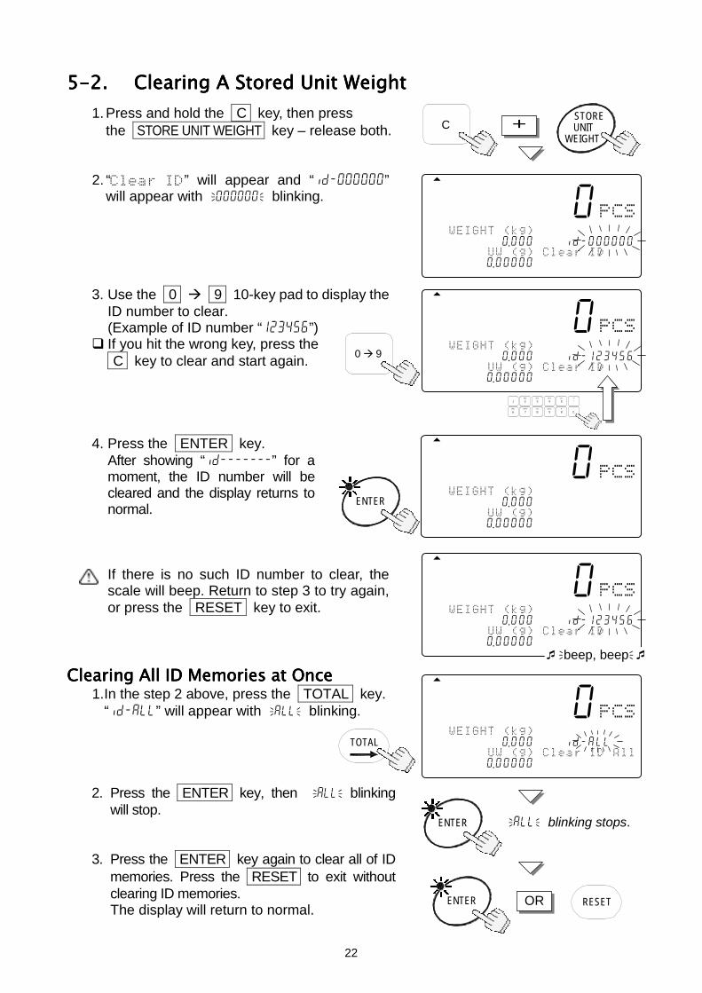
5-2.5-2.5-2.5-2. Clearing A Stored Unit WeightClearing A Stored Unit WeightClearing A Stored Unit WeightClearing A Stored Unit Weight1. Press and hold the C key, then press
the STORE UNIT WEIGHT key – release both.
2. “” will appear and “id-000000”will appear with000000blinking.
3. Use the 0 9 10-key pad to display theID number to clear.(Example of ID number “123456”)
If you hit the wrong key, press the C key to clear and start again.
4. Press the ENTER key.After showing “id-------” for amoment, the ID number will becleared and the display returns tonormal.
If there is no such ID number to clear, thescale will beep. Return to step 3 to try again,or press the RESET key to exit.
Clearing All ID Memories at OnceClearing All ID Memories at OnceClearing All ID Memories at OnceClearing All ID Memories at Once1.In the step 2 above, press the TOTAL key.
“id-all” will appear withallblinking.
2. Press the ENTER key, then allblinkingwill stop.
3. Press the ENTER key again to clear all of IDmemories. Press the RESET to exit withoutclearing ID memories.The display will return to normal.
CSTORE
WEIGHTUNIT+
8888810
123145678C0 .0004578id-000000
123451670 .0000045678901234567
0 9
8888810
123456178C0 .0004578id-123456
123451670 .0000045678901234567
TUV
DEFABC
MNO
6
1
7 8PQRS
2 3JKLGHI
09WXYZ
4
#
5
C
.
-----10
1234516---0 .000
123415670 .00000
ENTER
8888810
123451678-0 .0004578id-123456
123451670 .0000045678901234567 beep, beep
8888810
123145678C0 .0005678id-all
123451670 .00000
TOTAL
ENTER allblinking stops.
ENTER RESETOR
23
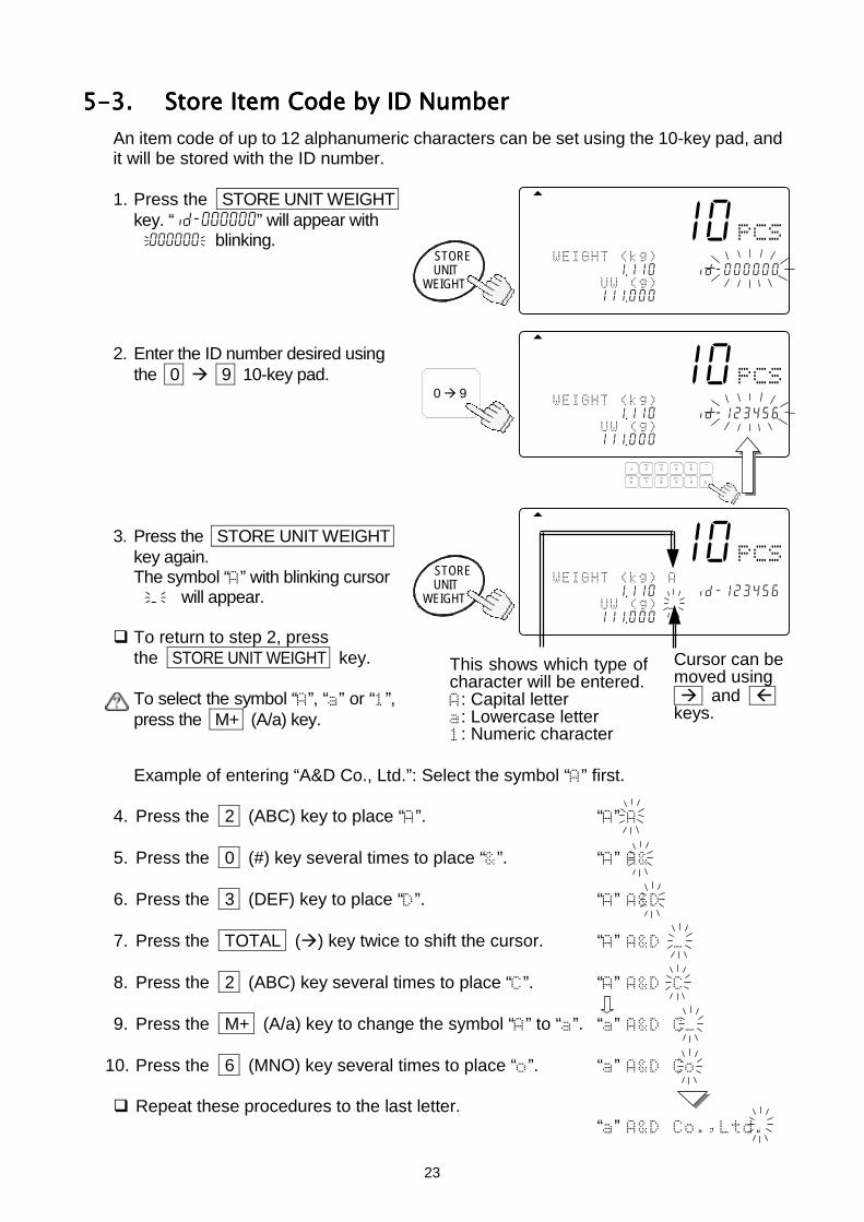
5-3.5-3.5-3.5-3. Store Item Code by ID NumberStore Item Code by ID NumberStore Item Code by ID NumberStore Item Code by ID NumberAn item code of up to 12 alphanumeric characters can be set using the 10-key pad, andit will be stored with the ID number.
1. Press the STORE UNIT WEIGHTkey. “id-000000” will appear with000000blinking.
2. Enter the ID number desired usingthe 0 9 10-key pad.
3. Press the STORE UNIT WEIGHTkey again.The symbol “” with blinking cursor_ will appear.
To return to step 2, pressthe STORE UNIT WEIGHT key.
To select the symbol “”, “” or “”,press the M+ (A/a) key.
Example of entering “A&D Co., Ltd.”: Select the symbol “” first.
4. Press the 2 (ABC) key to place “”. “”
5. Press the 0 (#) key several times to place “”. “”
6. Press the 3 (DEF) key to place “”. “”
7. Press the TOTAL () key twice to shift the cursor. “”
8. Press the 2 (ABC) key several times to place “”. “”
9. Press the M+ (A/a) key to change the symbol “” to “”. “”
10. Press the 6 (MNO) key several times to place “”. “”
Repeat these procedures to the last letter.“”
8888810
12345671891 .1104567id-000000
12345617111 .000
STORE
WEIGHTUNIT
STORE
WEIGHTUNIT
8888810
12345617891 .1104568id-123456
12345617111 .00045
Cursor can bemoved using and
keys.
0 9
8888810
12345617891 .1104578id-123456
12345617111 .000434567
TUV
DEFABC
MNO
6
1
7 8PQRS
2 3JKLGHI
09WXYZ
4
#
5
C
.
This shows which type ofcharacter will be entered.: Capital letter: Lowercase letter: Numeric character
24
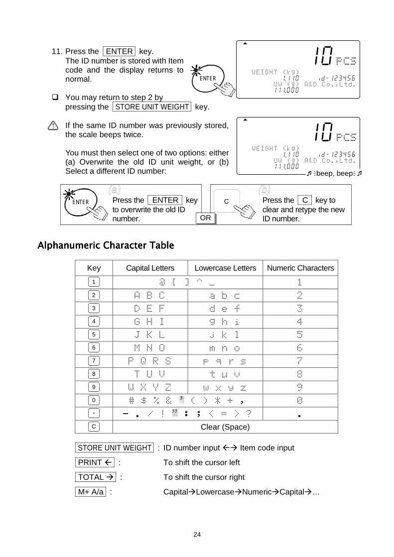
11. Press the ENTER key.The ID number is stored with Itemcode and the display returns tonormal.
You may return to step 2 bypressing the STORE UNIT WEIGHT key.
If the same ID number was previously stored,the scale beeps twice.
You must then select one of two options: either(a) Overwrite the old ID unit weight, or (b)Select a different ID number:
Alphanumeric Character TableAlphanumeric Character TableAlphanumeric Character TableAlphanumeric Character Table
Key Capital Letters Lowercase Letters Numeric Characters
!" #
$%& '() *
+,-. /012 3
456 789 :
;<=> ?@AB C
DEFG HIJK L
MN OPQR
Clear (Space)
STORE UNIT WEIGHT : ID number input Item code input
PRINT : To shift the cursor left
TOTAL : To shift the cursor right
M+ A/a : CapitalLowercaseNumericCapital…
-----10
123516-1--1 .11056 8id-123456 !"#$%"
12341567111 .000
ENTER
-----10
123456--1-1 .1105678id-123456 !"#$%"
1234567l111 .000beep, beep
Press the ENTER keyto overwrite the old IDnumber.
ENTER Press the C key toclear and retype the newID number.
C
OR
2
3
4
5
6
7
8
9
1
0
.
C
25
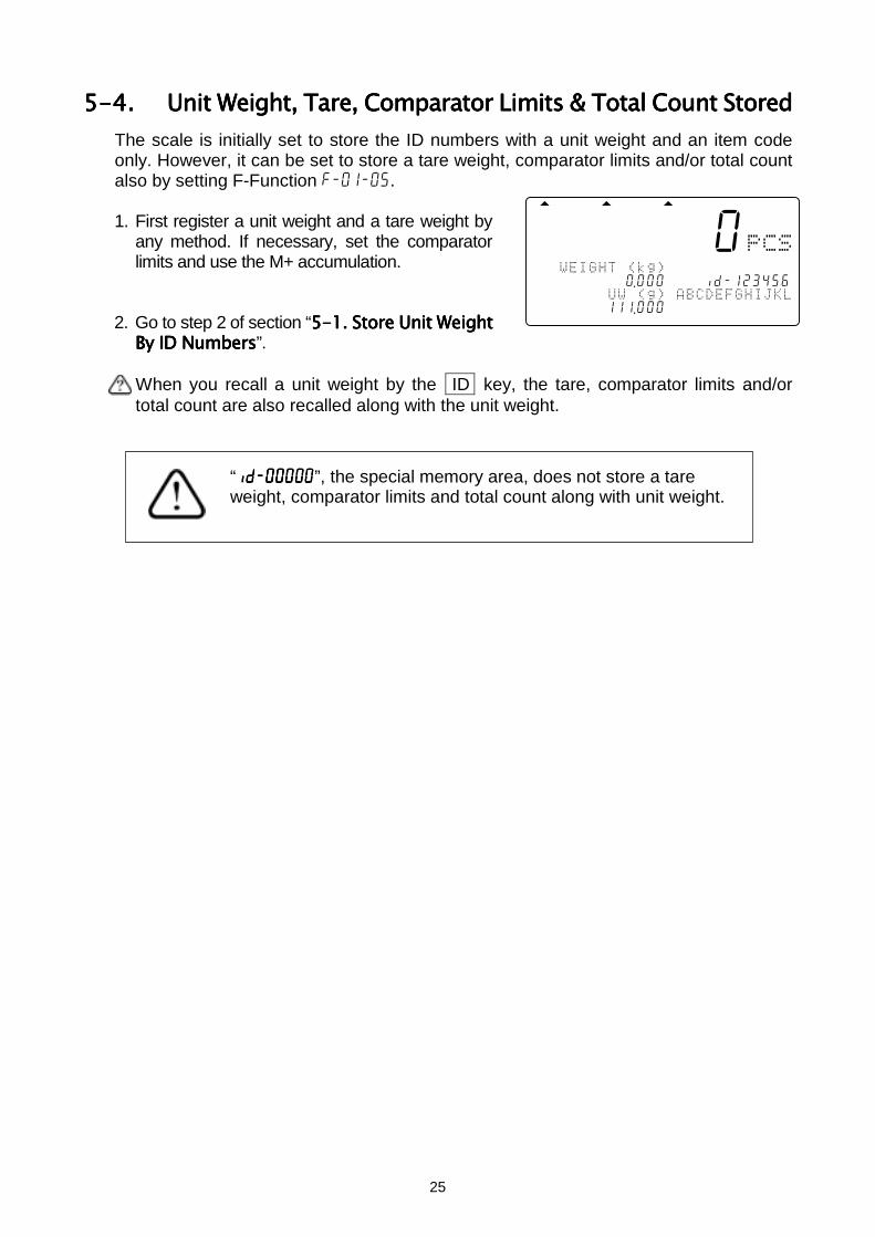
5-4.5-4.5-4.5-4. Unit Weight, Tare, Comparator Limits & Total Count StoredUnit Weight, Tare, Comparator Limits & Total Count StoredUnit Weight, Tare, Comparator Limits & Total Count StoredUnit Weight, Tare, Comparator Limits & Total Count StoredThe scale is initially set to store the ID numbers with a unit weight and an item codeonly. However, it can be set to store a tare weight, comparator limits and/or total countalso by setting F-Function f-01-05.
1. First register a unit weight and a tare weight byany method. If necessary, set the comparatorlimits and use the M+ accumulation.
2. Go to step 2 of section “5-15-15-15-1. Store Unit Weight. Store Unit Weight. Store Unit Weight. Store Unit WeightBy ID NumbersBy ID NumbersBy ID NumbersBy ID Numbers”.
When you recall a unit weight by the ID key, the tare, comparator limits and/ortotal count are also recalled along with the unit weight.
888-510
12345617890 .0004678id-123456 &'()$
12345617111 .000
“id-00000id-00000id-00000id-00000”, the special memory area, does not store a tareweight, comparator limits and total count along with unit weight.
26
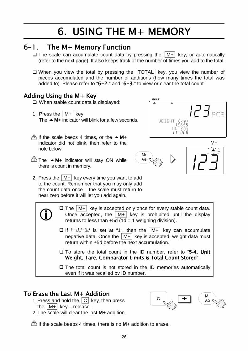
6.6.6.6. USING THE M+ MEMORYUSING THE M+ MEMORYUSING THE M+ MEMORYUSING THE M+ MEMORY6-1.6-1.6-1.6-1. The M+ Memory FunctionThe M+ Memory FunctionThe M+ Memory FunctionThe M+ Memory Function
The scale can accumulate count data by pressing the M+ key, or automatically(refer to the next page). It also keeps track of the number of times you add to the total.
When you view the total by pressing the TOTAL key, you view the number ofpieces accumulated and the number of additions (how many times the total wasadded to). Please refer to “6666-2-2-2-2....” and “6666-3.-3.-3.-3.” to view or clear the total count.
Adding Using the M+ KeyAdding Using the M+ KeyAdding Using the M+ KeyAdding Using the M+ Key When stable count data is displayed:
1. Press the M+ key.The M+ indicator will blink for a few seconds.
If the scale beeps 4 times, or the M+indicator did not blink, then refer to thenote below.
The M+ indicator will stay ON whilethere is count in memory.
2. Press the M+ key every time you want to addto the count. Remember that you may only addthe count data once – the scale must return tonear zero before it will let you add again.
To Erase the Last M+ AdditionTo Erase the Last M+ AdditionTo Erase the Last M+ AdditionTo Erase the Last M+ Addition1. Press and hold the C key, then press
the M+ key – release.2. The scale will clear the last M+ addition.
If the scale beeps 4 times, there is no M+ addition to erase.
The M+ key is accepted only once for every stable count data.Once accepted, the M+ key is prohibited until the displayreturns to less than +5d (1d = 1 weighing division).
If f-03-02 is set at “1”, then the M+ key can accumulatenegative data. Once the M+ key is accepted, weight data mustreturn within ±5d before the next accumulation.
To store the total count in the ID number, refer to “5-4. Unit. Unit. Unit. UnitWeight, Tare, Comparator Limits & Total Count StoredWeight, Tare, Comparator Limits & Total Count StoredWeight, Tare, Comparator Limits & Total Count StoredWeight, Tare, Comparator Limits & Total Count Stored”.
The total count is not stored in the ID memories automaticallyeven if it was recalled by ID number.
C + M+A/a
888-123
12345617813 .6554
12345617111 .000
123M+
M+A/a
STABLE
27
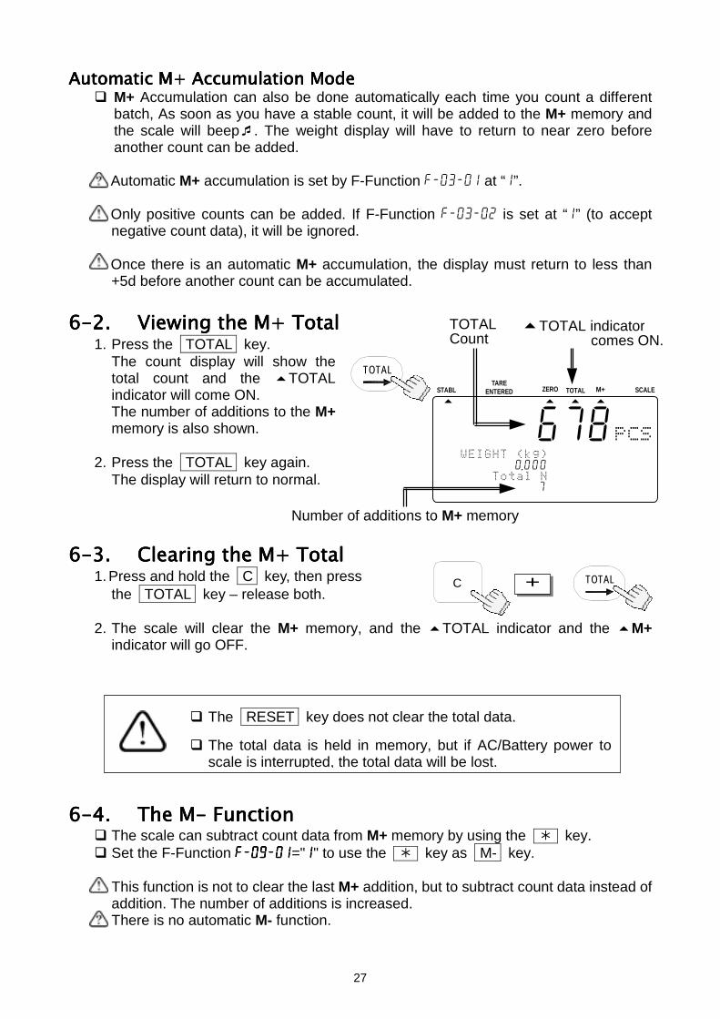
Automatic M+ Accumulation ModeAutomatic M+ Accumulation ModeAutomatic M+ Accumulation ModeAutomatic M+ Accumulation Mode M+ Accumulation can also be done automatically each time you count a different
batch, As soon as you have a stable count, it will be added to the M+ memory andthe scale will beep. The weight display will have to return to near zero beforeanother count can be added.
Automatic M+ accumulation is set by F-Function f-03-01 at “1”.
Only positive counts can be added. If F-Function f-03-02 is set at “1” (to acceptnegative count data), it will be ignored.
Once there is an automatic M+ accumulation, the display must return to less than+5d before another count can be accumulated.
6-2.6-2.6-2.6-2. Viewing the M+ TotalViewing the M+ TotalViewing the M+ TotalViewing the M+ Total1. Press the TOTAL key.
The count display will show thetotal count and the TOTALindicator will come ON.The number of additions to the M+memory is also shown.
2. Press the TOTAL key again.The display will return to normal.
6-3.6-3.6-3.6-3. ClearClearClearClearing the M+ Totaling the M+ Totaling the M+ Totaling the M+ Total1. Press and hold the C key, then press
the TOTAL key – release both.
2. The scale will clear the M+ memory, and the TOTAL indicator and the M+indicator will go OFF.
6-4.6-4.6-4.6-4. The M- FunctionThe M- FunctionThe M- FunctionThe M- Function The scale can subtract count data from M+ memory by using the key. Set the F-Function f-09-01f-09-01f-09-01f-09-01="1111" to use the key as M- key.
This function is not to clear the last M+ addition, but to subtract count data instead ofaddition. The number of additions is increased.There is no automatic M- function.
TOTALC +
The RESET key does not clear the total data.
The total data is held in memory, but if AC/Battery power toscale is interrupted, the total data will be lost.
TOTAL
TOTAL indicatorcomes ON.
TOTALCount
Number of additions to M+ memory
STABL
8888678
123456718-0 .000 !%*
12345167111007
ZERO TOTAL M+TARE
ENTERED SCALE
28
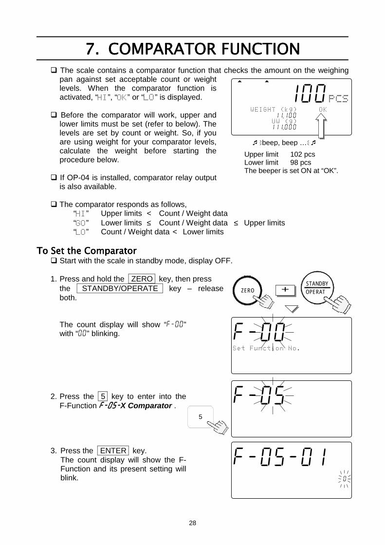
7.7.7.7. COMPARATOR FUNCTIONCOMPARATOR FUNCTIONCOMPARATOR FUNCTIONCOMPARATOR FUNCTION The scale contains a comparator function that checks the amount on the weighing
pan against set acceptable count or weightlevels. When the comparator function isactivated, “”, “” or “” is displayed.
Before the comparator will work, upper andlower limits must be set (refer to below). Thelevels are set by count or weight. So, if youare using weight for your comparator levels,calculate the weight before starting theprocedure below.
If OP-04 is installed, comparator relay outputis also available.
The comparator responds as follows,“” Upper limits < Count / Weight data“” Lower limits ≤ Count / Weight data ≤ Upper limits“” Count / Weight data < Lower limits
To Set To Set To Set To Set thethethethe Comparator Comparator Comparator Comparator Start with the scale in standby mode, display OFF.
1. Press and hold the ZERO key, then pressthe STANDBY/OPERATE key – releaseboth.
The count display will show “f-00”with “00” blinking.
2. Press the 5 key to enter into theF-Function f-05-f-05-f-05-f-05-X Comparator .
3. Press the ENTER key.The count display will show the F-Function and its present setting willblink.
888-100
&+)$+
121341567811 .100578id-123456 &'()$
123451167111 .000
beep, beep …
Upper limit 102 pcsLower limit 98 pcsThe beeper is set ON at “OK”.
ZERO + OPERATSTANDBY
5
f-05-01
!%!
12345678C000045678id-000000
12345670 .0000045678901234567
f-000
%',-.%/!-*!"
12345678C000045678id-000000
12345670 .0000045678901234567
f-05-00
!%!
12345678C000045678id-000000
12345670 .0000045678901234567
29
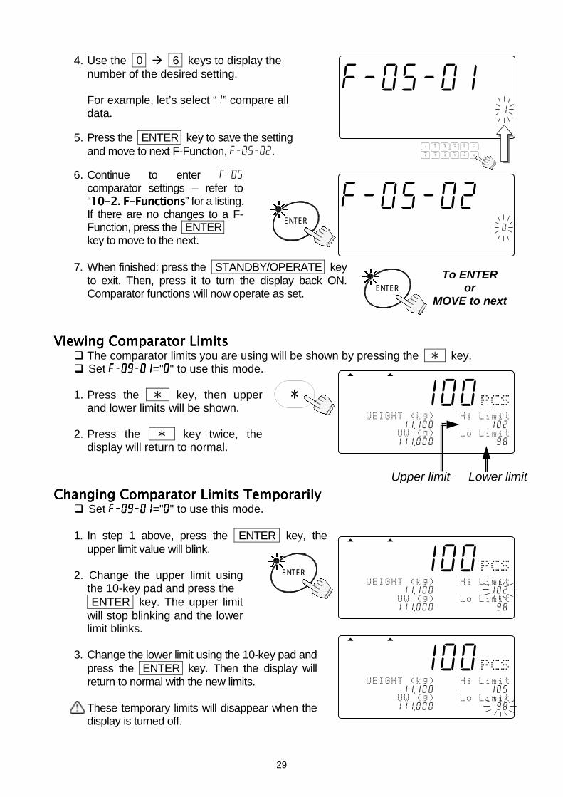
4. Use the 0 6 keys to display thenumber of the desired setting.
For example, let’s select “1” compare alldata.
5. Press the ENTER key to save the settingand move to next F-Function, f-05-02.
6. Continue to enter f-05comparator settings – refer to“10-210-210-210-2. F-Functions. F-Functions. F-Functions. F-Functions” for a listing.If there are no changes to a F-Function, press the ENTER key to move to the next.
7. When finished: press the STANDBY/OPERATE keyto exit. Then, press it to turn the display back ON.Comparator functions will now operate as set.
Viewing Comparator LimitsViewing Comparator LimitsViewing Comparator LimitsViewing Comparator Limits The comparator limits you are using will be shown by pressing the key. Set f-09-01f-09-01f-09-01f-09-01="0000" to use this mode.
1. Press the key, then upperand lower limits will be shown.
2. Press the key twice, thedisplay will return to normal.
Changing Comparator Limits TemporarilyChanging Comparator Limits TemporarilyChanging Comparator Limits TemporarilyChanging Comparator Limits Temporarily Set f-09-01f-09-01f-09-01f-09-01="0000" to use this mode.
1. In step 1 above, press the ENTER key, theupper limit value will blink.
2. Change the upper limit usingthe 10-key pad and press the ENTER key. The upper limitwill stop blinking and the lowerlimit blinks.
3. Change the lower limit using the 10-key pad andpress the ENTER key. Then the display willreturn to normal with the new limits.
These temporary limits will disappear when thedisplay is turned off.
f-05-01
!%!
12345678C000045678id-000001
12345670 .0000045678901234567
TUV
DEFABC
MNO
6
1
7 8PQRS
2 3JKLGHI
09WXYZ
4
#
5
C
.
ENTER
f-05-02
!%!
12345678C000045678id-000000
12345670 .0000045678901234567
ENTERTo ENTER
orMOVE to next
888-100
&/$//%
121341567811 .100578id-123102 &$!$//%
123451167111 .000123456789098
888-100
&/$//%
121341567811 .100578id-123105 &$!$//%
123451167111 .000123456789098
ENTER
888-100
&/$//%
121341567811 .100578id-123102 &$!$//%
123451167111 .000123456789098
Upper limit Lower limit
30
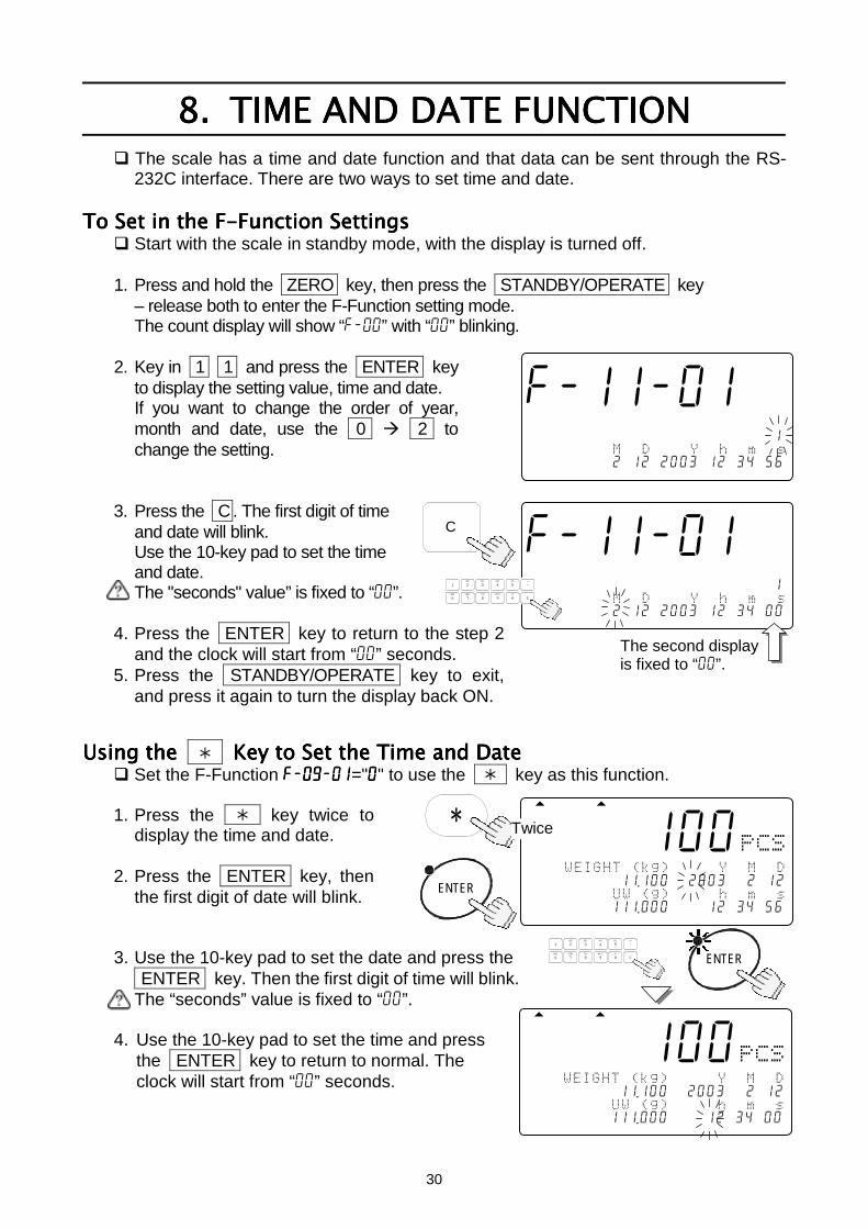
8.8.8.8. TIME AND DATE FUNCTIONTIME AND DATE FUNCTIONTIME AND DATE FUNCTIONTIME AND DATE FUNCTION The scale has a time and date function and that data can be sent through the RS-
232C interface. There are two ways to set time and date.
To Set in the F-Function SettingsTo Set in the F-Function SettingsTo Set in the F-Function SettingsTo Set in the F-Function Settings Start with the scale in standby mode, with the display is turned off.
1. Press and hold the ZERO key, then press the STANDBY/OPERATE key– release both to enter the F-Function setting mode.The count display will show “f-00” with “00” blinking.
2. Key in 1 1 and press the ENTER keyto display the setting value, time and date.If you want to change the order of year,month and date, use the 0 2 tochange the setting.
3. Press the C . The first digit of timeand date will blink.Use the 10-key pad to set the timeand date.The "seconds" value” is fixed to “00”.
4. Press the ENTER key to return to the step 2and the clock will start from “00” seconds.
5. Press the STANDBY/OPERATE key to exit,and press it again to turn the display back ON.
Using Using Using Using the the the the Key to Set Key to Set Key to Set Key to Set thethethethe Time and Date Time and Date Time and Date Time and Date Set the F-Function f-09-01f-09-01f-09-01f-09-01="0000" to use the key as this function.
1. Press the key twice todisplay the time and date.
2. Press the ENTER key, thenthe first digit of date will blink.
3. Use the 10-key pad to set the date and press the ENTER key. Then the first digit of time will blink.The “seconds” value is fixed to “00”.
4. Use the 10-key pad to set the time and pressthe ENTER key to return to normal. Theclock will start from “00” seconds.
f-11-01
!%!
123456789012345678901234561 012
12345670 .0201202003012034056
C
f-11-01
!%!
123456789012345678901234561 012
12345670 .0201202003012034000
The second displayis fixed to “00”.
TUV
DEFABC
MNO
6
1
7 8PQRS
2 3JKLGHI
09WXYZ
4
#
5
C
.
888-100
&0
121341567811 .100572003 2 12 &12
123451167111 .000123412 34 56
888-100
&0
121341567811 .100572003 2 12 &12
123451167111 .000123412 34 00
ENTER
Twice
TUV
DEFABC
MNO
6
1
7 8PQRS
2 3JKLGHI
09WXYZ
4
#
5
C
.
ENTER
31
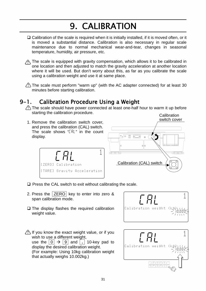
9.9.9.9. CALIBRATIONCALIBRATIONCALIBRATIONCALIBRATION Calibration of the scale is required when it is initially installed, if it is moved often, or it
is moved a substantial distance. Calibration is also necessary in regular scalemaintenance due to normal mechanical wear-and-tear, changes in seasonaltemperature, humidity, air pressure, etc.
The scale is equipped with gravity compensation, which allows it to be calibrated inone location and then adjusted to match the gravity acceleration at another locationwhere it will be used. But don’t worry about this, as far as you calibrate the scaleusing a calibration weight and use it at same place.
The scale must perform "warm up" (with the AC adapter connected) for at least 30minutes before starting calibration.
9-1.9-1.9-1.9-1. Calibration Procedure Using a WeightCalibration Procedure Using a WeightCalibration Procedure Using a WeightCalibration Procedure Using a WeightThe scale should have power connected at least one-half hour to warm it up beforestarting the calibration procedure.
1. Remove the calibration switch cover,and press the calibration (CAL) switch.The scale shows “Cal” in the countdisplay.
Press the CAL switch to exit without calibrating the scale.
2. Press the ZERO key to enter into zero &span calibration mode.
The display flashes the required calibrationweight value.
If you know the exact weight value, or if youwish to use a different weight,use the 0 9 and . 10-key pad todisplay the desired calibration weight.(For example: Using 10kg calibration weightthat actually weighs 10.002kg.)
88Cal10
/3%/!-4/1%
Cal4567890123aaaaaaaaa10 .000567/%8..%/!-
88Cal10
/3%/!-4/1%
Cal4567890123aaaaaaaaa10 .002567/%8..%/!-
1234567890123
TUV
DEFABC
MNO
6
1
7 8PQRS
2 3JKLGHI
09WXYZ
4
#
5
C
.
88Cal10
59+6/3%/!-
1234567890123567/%8..%/!-
1234567890123
Calibrationswitch cover
Calibration (CAL) switch
32
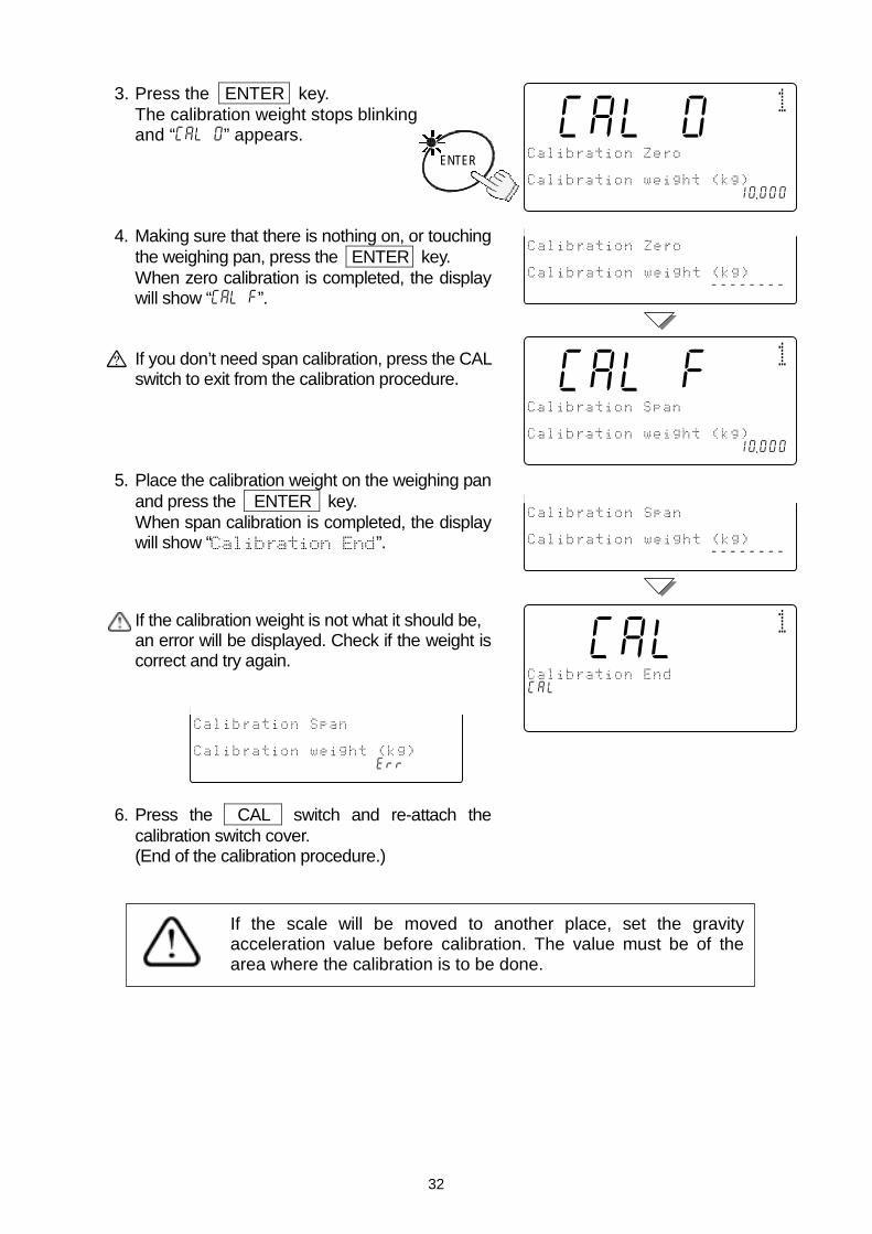
3. Press the ENTER key.The calibration weight stops blinkingand “Cal 0” appears.
4. Making sure that there is nothing on, or touchingthe weighing pan, press the ENTER key.When zero calibration is completed, the displaywill show “Cal f”.
If you don’t need span calibration, press the CALswitch to exit from the calibration procedure.
5. Place the calibration weight on the weighing panand press the ENTER key.When span calibration is completed, the displaywill show “”.
If the calibration weight is not what it should be,an error will be displayed. Check if the weight iscorrect and try again.
6. Press the CAL switch and re-attach thecalibration switch cover.(End of the calibration procedure.)
ENTER
8Call00
/3%/!-9!
Cala0/3%/!-4/1%
123456789012345678901210 .000
8Callf0
/3%/!--
Calaf/3%/!-4/1%
123456789012345678901210 .000
/3%/!-9!
Cala0/3%/!-4/1%
1234567890123456789--------
/3%/!--
Calaf/3%/!-4/1%
1234567890123456789--------
88Cal10
/3%/!--
Cala/3%/!-4/1%
123456789012345678901210 .000/3%/!--
Calaf/3%/!-4/1%
1234567890123456789err
If the scale will be moved to another place, set the gravityacceleration value before calibration. The value must be of thearea where the calibration is to be done.
33
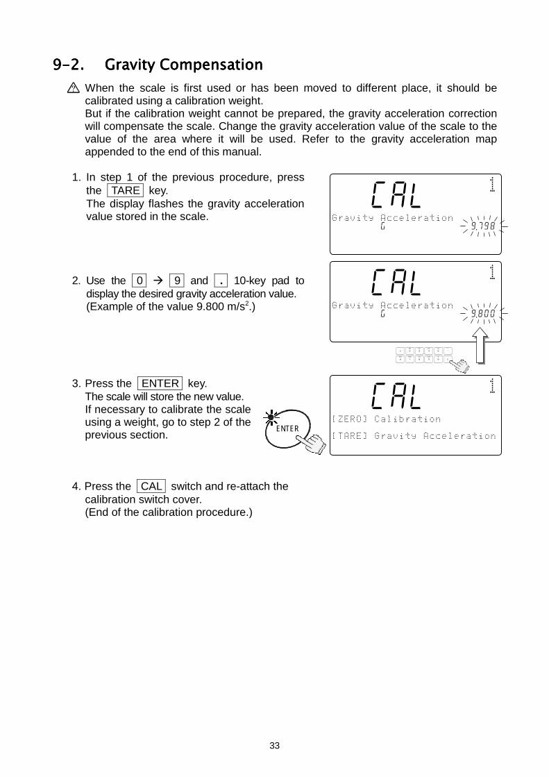
9-2.9-2.9-2.9-2. Gravity CompensationGravity CompensationGravity CompensationGravity CompensationWhen the scale is first used or has been moved to different place, it should becalibrated using a calibration weight.But if the calibration weight cannot be prepared, the gravity acceleration correctionwill compensate the scale. Change the gravity acceleration value of the scale to thevalue of the area where it will be used. Refer to the gravity acceleration mapappended to the end of this manual.
1. In step 1 of the previous procedure, pressthe TARE key.The display flashes the gravity accelerationvalue stored in the scale.
2. Use the 0 9 and . 10-key pad todisplay the desired gravity acceleration value.(Example of the value 9.800 m/s2.)
3. Press the ENTER key.The scale will store the new value.If necessary to calibrate the scaleusing a weight, go to step 2 of theprevious section.
4. Press the CAL switch and re-attach thecalibration switch cover.(End of the calibration procedure.)
88Cal10
7/%8..%/!-
Cal45678g0123aaaaaaaaaa9 .798!87/%8..%/!-
1234567890123
ENTER
88Cal10
7/%8..%/!-
Cal45678g0123aaaaaaaaa19 .800567/%8..%/!-
1234567890123
TUV
DEFABC
MNO
6
1
7 8PQRS
2 3JKLGHI
09WXYZ
4
#
5
C
.
88Cal10
59+6/3%/!-
1234567890123567/%8..%/!-
1234567890123
34
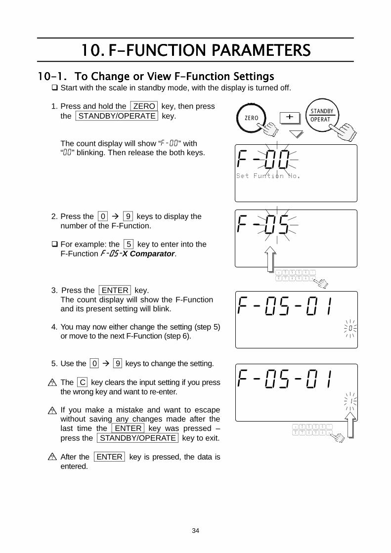
10.10.10.10. F-FUNCTION PARAMETERSF-FUNCTION PARAMETERSF-FUNCTION PARAMETERSF-FUNCTION PARAMETERS10-1.10-1.10-1.10-1. To Change or View F-Function SettingsTo Change or View F-Function SettingsTo Change or View F-Function SettingsTo Change or View F-Function Settings
Start with the scale in standby mode, with the display is turned off.
1. Press and hold the ZERO key, then pressthe STANDBY/OPERATE key.
The count display will show “f-00” with“00” blinking. Then release the both keys.
2. Press the 0 9 keys to display thenumber of the F-Function.
For example: the 5 key to enter into theF-Function f-05-f-05-f-05-f-05-X Comparator.
3. Press the ENTER key.The count display will show the F-Functionand its present setting will blink.
4. You may now either change the setting (step 5)or move to the next F-Function (step 6).
5. Use the 0 9 keys to change the setting.
The C key clears the input setting if you pressthe wrong key and want to re-enter.
If you make a mistake and want to escapewithout saving any changes made after thelast time the ENTER key was pressed –press the STANDBY/OPERATE key to exit.
After the ENTER key is pressed, the data isentered.
f-05-00
!%!
12345678C000045678id-000000
12345670 .0000045678901234567
TUV
DEFABC
MNO
6
1
7 8PQRS
2 3JKLGHI
09WXYZ
4
#
5
C
.
ZERO + OPERATSTANDBY
f-05-01
!%!
12345678C000045678id-000000
12345670 .0000045678901234567
f-05-01
!%!
12345678C000045678id-000001
12345670 .0000045678901234567
TUV
DEFABC
MNO
6
1
7 8PQRS
2 3JKLGHI
09WXYZ
4
#
5
C
.
f-000
%',-%/!-*!"
12345678C000045678id-000000
12345670 .0000045678901234567
35
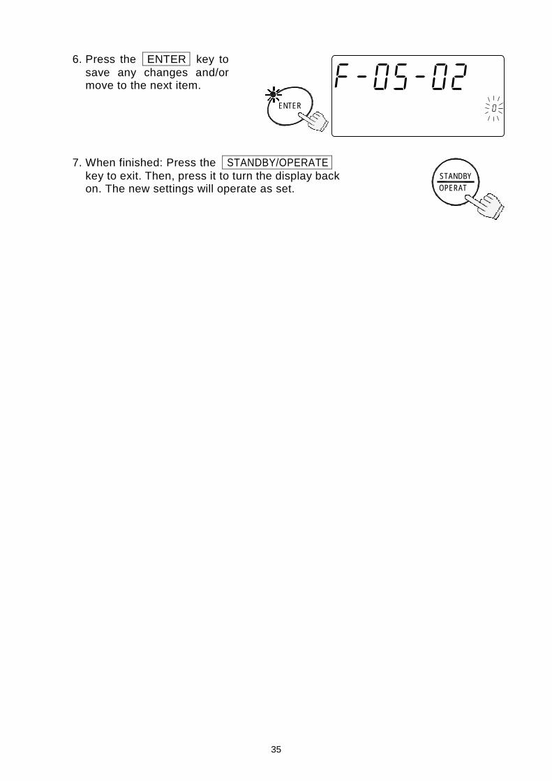
6. Press the ENTER key tosave any changes and/ormove to the next item.
7. When finished: Press the STANDBY/OPERATEkey to exit. Then, press it to turn the display backon. The new settings will operate as set.
ENTER
f-05-02
!%!
12345678C000045678id-000000
12345670 .0000045678901234567
OPERATSTANDBY
36
10-2.10-2.10-2.10-2. F-FunctionsF-FunctionsF-FunctionsF-Functions “” designates factory settings.
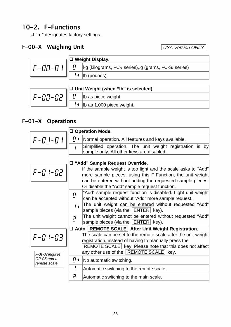
F-00-F-00-F-00-F-00-X Weighing UnitX Weighing UnitX Weighing UnitX Weighing Unit
Weight Display.
0000 kg (kilograms, FC-i series),.g (grams, FC-Si series)
1111 lb (pounds).
Unit Weight (when “lb” is selected).
0000 lb as piece weight.
1111 lb as 1,000 piece weight.
F-01-F-01-F-01-F-01-X OperationsX OperationsX OperationsX Operations Operation Mode.
0000 Normal operation. All features and keys available.
1111 Simplified operation. The unit weight registration is bysample only. All other keys are disabled.
“Add” Sample Request Override.If the sample weight is too light and the scale asks to “Add”more sample pieces, using this F-Function, the unit weightcan be entered without adding the requested sample pieces.Or disable the “Add” sample request function.
0000“Add” sample request function is disabled. Light unit weightcan be accepted without “Add” more sample request.
1111The unit weight can be entered without requested “Add”sample pieces (via the ENTER key).
2222The unit weight cannot be entered without requested “Add”sample pieces (via the ENTER key).
Auto REMOTE SCALE After Unit Weight Registration.The scale can be set to the remote scale after the unit weightregistration, instead of having to manually press the REMOTE SCALE key. Please note that this does not affectany other use of the REMOTE SCALE key.
0000 No automatic switching.
1111 Automatic switching to the remote scale.
2222 Automatic switching to the main scale.
f-01-01f-01-01f-01-01f-01-01
f-01-02f-01-02f-01-02f-01-02
f-01-03f-01-03f-01-03f-01-03
F-01-03 requiresOP-05 and aremote scale
f-00-01f-00-01f-00-01f-00-01
USA Version ONLY
f-00-02f-00-02f-00-02f-00-02
37
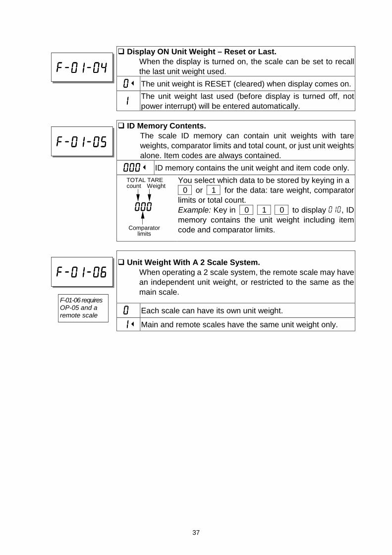
Display ON Unit Weight – Reset or Last.When the display is turned on, the scale can be set to recallthe last unit weight used.
0000 The unit weight is RESET (cleared) when display comes on.
1111The unit weight last used (before display is turned off, notpower interrupt) will be entered automatically.
ID Memory Contents.The scale ID memory can contain unit weights with tareweights, comparator limits and total count, or just unit weightsalone. Item codes are always contained.
000000000000 ID memory contains the unit weight and item code only.You select which data to be stored by keying in a 0 or 1 for the data: tare weight, comparatorlimits or total count.Example: Key in 0 1 0 to display 010, IDmemory contains the unit weight including itemcode and comparator limits.
Unit Weight With A 2 Scale System.When operating a 2 scale system, the remote scale may havean independent unit weight, or restricted to the same as themain scale.
0000 Each scale can have its own unit weight.
1111 Main and remote scales have the same unit weight only.
f-01-04f-01-04f-01-04f-01-04
f-01-06f-01-06f-01-06f-01-06
F-01-06 requiresOP-05 and aremote scale
f-01-05f-01-05f-01-05f-01-05
000000000000
Comparator limits
TOTAL TARE count Weight
38
F-02-F-02-F-02-F-02-X ACAI Operation & Min. Unit WeightX ACAI Operation & Min. Unit WeightX ACAI Operation & Min. Unit WeightX ACAI Operation & Min. Unit Weight
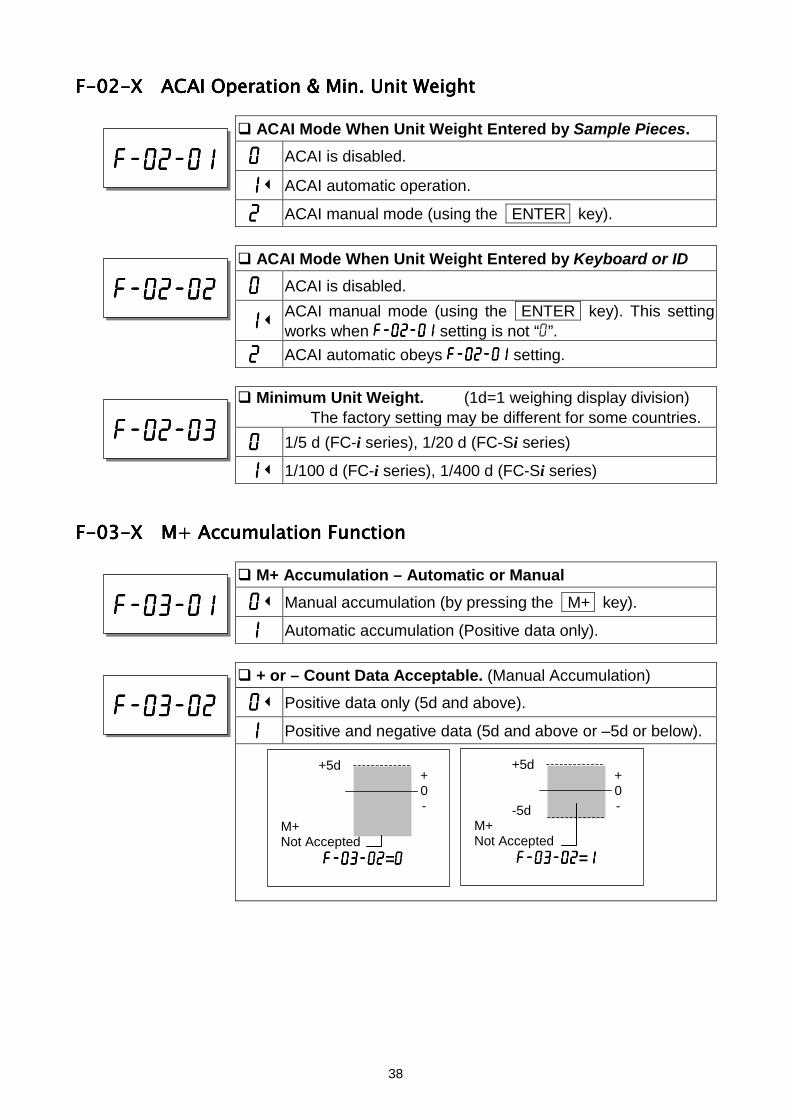
ACAI Mode When Unit Weight Entered by Sample Pieces.
0000 ACAI is disabled.
1111 ACAI automatic operation.
2222 ACAI manual mode (using the ENTER key).
ACAI Mode When Unit Weight Entered by Keyboard or ID
0000 ACAI is disabled.
1111ACAI manual mode (using the ENTER key). This settingworks when f-02-01f-02-01f-02-01f-02-01 setting is not “0”.
2222 ACAI automatic obeys f-02-01f-02-01f-02-01f-02-01 setting.
Minimum Unit Weight. (1d=1 weighing display division)The factory setting may be different for some countries.
0000 1/5 d (FC-i series), 1/20 d (FC-Si series)
1111 1/100 d (FC-i series), 1/400 d (FC-Si series)
F-03-F-03-F-03-F-03-X M+ Accumulation FunctionX M+ Accumulation FunctionX M+ Accumulation FunctionX M+ Accumulation Function
M+ Accumulation – Automatic or Manual
0000 Manual accumulation (by pressing the M+ key).
1111 Automatic accumulation (Positive data only).
+ or – Count Data Acceptable. (Manual Accumulation)
0000 Positive data only (5d and above).
1111 Positive and negative data (5d and above or –5d or below).
f-02-01f-02-01f-02-01f-02-01
f-02-02f-02-02f-02-02f-02-02
f-02-03f-02-03f-02-03f-02-03
f-03-01f-03-01f-03-01f-03-01
f-03-02f-03-02f-03-02f-03-02
+5d
M+Not Accepted
f-03-02f-03-02f-03-02f-03-02=0000
+0-
+5d
-5dM+Not Accepted
f-03-02f-03-02f-03-02f-03-02=1111
+0-
39
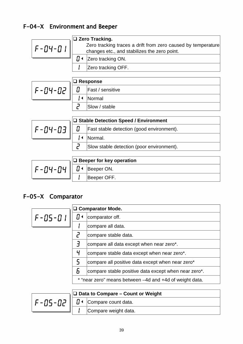
F-04-F-04-F-04-F-04-X Environment and BeeperX Environment and BeeperX Environment and BeeperX Environment and Beeper
Zero Tracking.Zero tracking traces a drift from zero caused by temperaturechanges etc., and stabilizes the zero point.
0000 Zero tracking ON.
1111 Zero tracking OFF.
Response
0000 Fast / sensitive
1111 Normal
2222 Slow / stable
Stable Detection Speed / Environment
0000 Fast stable detection (good environment).
1111 Normal.
2222 Slow stable detection (poor environment).
Beeper for key operation
0000 Beeper ON.
1111 Beeper OFF.
F-05-F-05-F-05-F-05-X ComparatorX ComparatorX ComparatorX Comparator
Comparator Mode.
0000 comparator off.
1111 compare all data.
2222 compare stable data.
3333 compare all data except when near zero*.
4444 compare stable data except when near zero*.
5555 compare all positive data except when near zero*
6666 compare stable positive data except when near zero*.
* “near zero” means between –4d and +4d of weight data.
Data to Compare – Count or Weight
0000 Compare count data.
1111 Compare weight data.
f-04-01f-04-01f-04-01f-04-01
f-04-02f-04-02f-04-02f-04-02
f-04-03f-04-03f-04-03f-04-03
f-04-04f-04-04f-04-04f-04-04
f-05-01f-05-01f-05-01f-05-01
f-05-02f-05-02f-05-02f-05-02
40
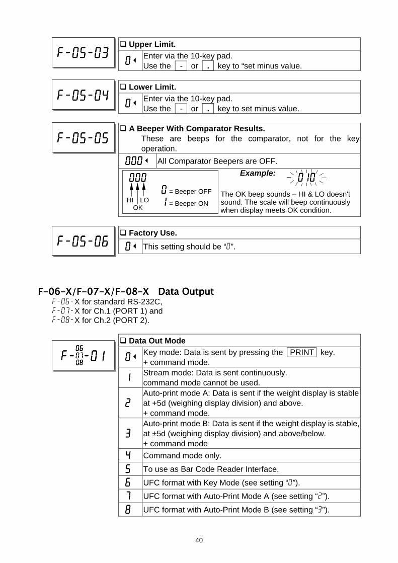
010010010010
Upper Limit.
0000Enter via the 10-key pad.Use the - or . key to “set minus value.
Lower Limit.
0000Enter via the 10-key pad.Use the - or . key to set minus value.
A Beeper With Comparator Results.These are beeps for the comparator, not for the keyoperation.
000000000000 All Comparator Beepers are OFF.Example:
The OK beep sounds – HI & LO doesn'tsound. The scale will beep continuouslywhen display meets OK condition.
Factory Use.
0000 This setting should be “0”.
F-06-X/F-07-X/F-08-F-06-X/F-07-X/F-08-F-06-X/F-07-X/F-08-F-06-X/F-07-X/F-08-X Data OutputX Data OutputX Data OutputX Data Outputf-06-X for standard RS-232C,f-07-X for Ch.1 (PORT 1) andf-08-X for Ch.2 (PORT 2).
Data Out Mode
0000Key mode: Data is sent by pressing the PRINT key.+ command mode.
1111Stream mode: Data is sent continuously.command mode cannot be used.
2222Auto-print mode A: Data is sent if the weight display is stableat +5d (weighing display division) and above.+ command mode.
3333Auto-print mode B: Data is sent if the weight display is stable,at ±5d (weighing display division) and above/below.+ command mode
4444 Command mode only.
5555 To use as Bar Code Reader Interface.
6666 UFC format with Key Mode (see setting “0”).
7777 UFC format with Auto-Print Mode A (see setting “2”).
8888 UFC format with Auto-Print Mode B (see setting “3”).
f-05-05f-05-05f-05-05f-05-05
000000000000 0000 = Beeper OFF
1111 = Beeper ONHI LOOK
f-05-06f-05-06f-05-06f-05-06
f-f-f-f-X-01-01-01-01060606060707070708080808
f-05-03f-05-03f-05-03f-05-03
f-05-04f-05-04f-05-04f-05-04
41
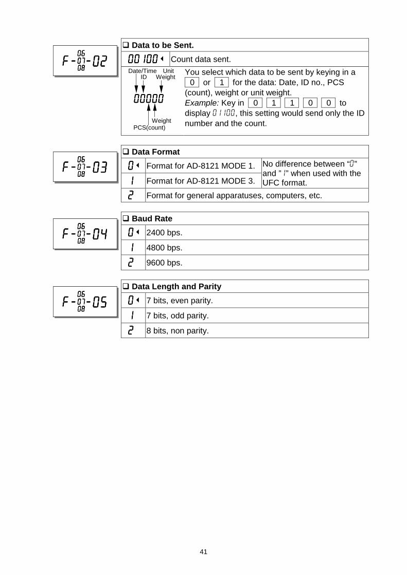
Data to be Sent.
00100001000010000100 Count data sent.You select which data to be sent by keying in a 0 or 1 for the data: Date, ID no., PCS(count), weight or unit weight.Example: Key in 0 1 1 0 0 todisplay 01100, this setting would send only the IDnumber and the count.
Data Format
0000 Format for AD-8121 MODE 1.
1111 Format for AD-8121 MODE 3.
No difference between “0”and ”1” when used with theUFC format.
2222 Format for general apparatuses, computers, etc.
Baud Rate
0000 2400 bps.
1111 4800 bps.
2222 9600 bps.
Data Length and Parity
0000 7 bits, even parity.
1111 7 bits, odd parity.
2222 8 bits, non parity.
00000000000000000000
WeightPCS(count)
Date/Time Unit ID Weight
f-f-f-f-X-02-02-02-02060606060707070708080808
f-f-f-f-X-03-03-03-03060606060707070708080808
f-f-f-f-X-04-04-04-04060606060707070708080808
f-f-f-f-X-05-05-05-05060606060707070708080808
42
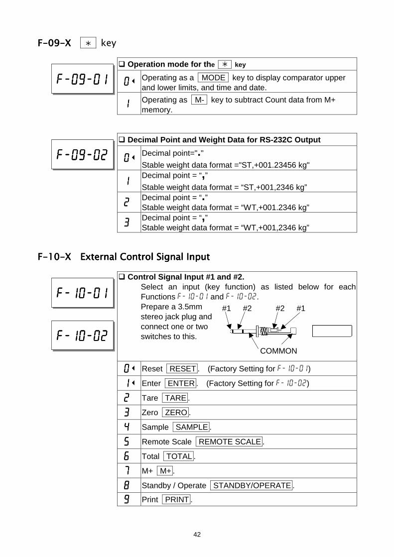
F-09-X F-09-X F-09-X F-09-X key
Operation mode for the key
0000 Operating as a MODE key to display comparator upperand lower limits, and time and date.
1111 Operating as M- key to subtract Count data from M+memory.
Decimal Point and Weight Data for RS-232C Output
0000Decimal point="."Stable weight data format ="ST,+001.23456 kg"
1111Decimal point = “,”Stable weight data format = “ST,+001,2346 kg”
2222Decimal point = “.”Stable weight data format = “WT,+001.2346 kg”
3333Decimal point = “,”Stable weight data format = “WT,+001,2346 kg”
F-10-F-10-F-10-F-10-X External Control Signal InputX External Control Signal InputX External Control Signal InputX External Control Signal Input
Control Signal Input #1 and #2.Select an input (key function) as listed below for eachFunctions f-10-01 and f-10-02.Prepare a 3.5mmstereo jack plug andconnect one or twoswitches to this.
0000 Reset RESET . (Factory Setting for f-10-01)
1111 Enter ENTER . (Factory Setting for f-10-02)
2222 Tare TARE .
3333 Zero ZERO .
4444 Sample SAMPLE .
5555 Remote Scale REMOTE SCALE .
6666 Total TOTAL .
7777 M+ M+ .
8888 Standby / Operate STANDBY/OPERATE .
9999 Print PRINT .
f-10-01f-10-01f-10-01f-10-01
f-10-02f-10-02f-10-02f-10-02
f-09-01f-09-01f-09-01f-09-01
#1 #2
COMMON
#2 #1
f-09-02f-09-02f-09-02f-09-02
43
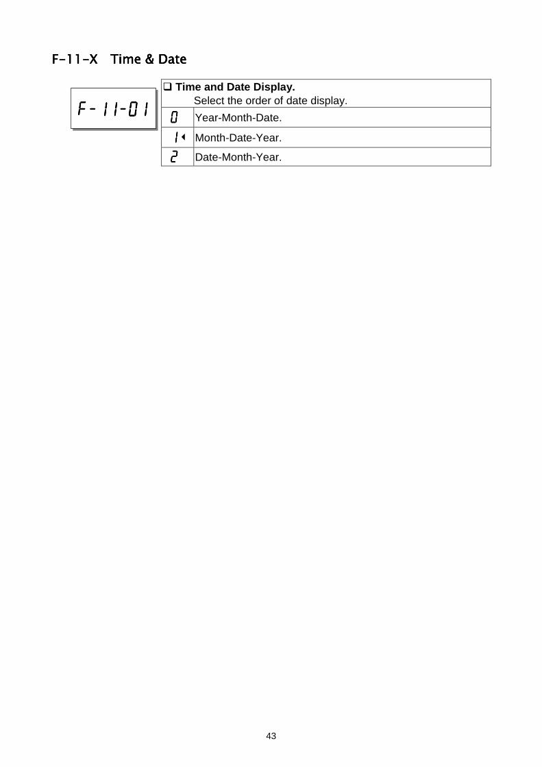
F-11-F-11-F-11-F-11-X Time & DateX Time & DateX Time & DateX Time & Date
Time and Date Display.Select the order of date display.
0000 Year-Month-Date.
1111 Month-Date-Year.
2222 Date-Month-Year.
f-11-01f-11-01f-11-01f-11-01
44
8888810
A
12134567891 .110
12341567111 .000
8888821
A
12134567892 .331
12341567111 .000
ACAI
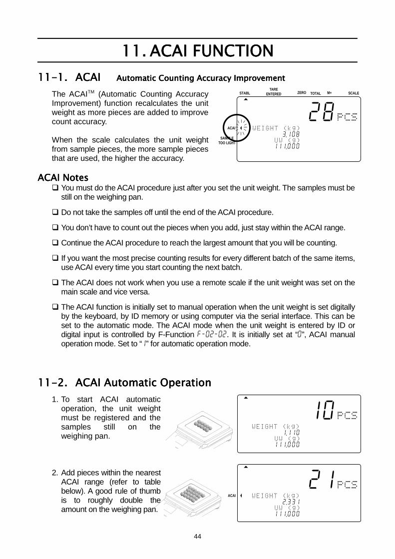
11.11.11.11. ACAI FUNCTIONACAI FUNCTIONACAI FUNCTIONACAI FUNCTION11-1.11-1.11-1.11-1. ACAI ACAI ACAI ACAI Automatic Counting Accuracy ImprovementAutomatic Counting Accuracy ImprovementAutomatic Counting Accuracy ImprovementAutomatic Counting Accuracy Improvement
The ACAITM (Automatic Counting AccuracyImprovement) function recalculates the unitweight as more pieces are added to improvecount accuracy.
When the scale calculates the unit weightfrom sample pieces, the more sample piecesthat are used, the higher the accuracy.
ACAI NotesACAI NotesACAI NotesACAI Notes You must do the ACAI procedure just after you set the unit weight. The samples must be
still on the weighing pan.
Do not take the samples off until the end of the ACAI procedure.
You don’t have to count out the pieces when you add, just stay within the ACAI range.
Continue the ACAI procedure to reach the largest amount that you will be counting.
If you want the most precise counting results for every different batch of the same items,use ACAI every time you start counting the next batch.
The ACAI does not work when you use a remote scale if the unit weight was set on themain scale and vice versa.
The ACAI function is initially set to manual operation when the unit weight is set digitallyby the keyboard, by ID memory or using computer via the serial interface. This can beset to the automatic mode. The ACAI mode when the unit weight is entered by ID ordigital input is controlled by F-Function f-02-02. It is initially set at “0”, ACAI manualoperation mode. Set to “1” for automatic operation mode.
11-2.11-2.11-2.11-2. ACAI Automatic OperationACAI Automatic OperationACAI Automatic OperationACAI Automatic Operation1. To start ACAI automatic
operation, the unit weightmust be registered and thesamples still on theweighing pan.
2. Add pieces within the nearestACAI range (refer to tablebelow). A good rule of thumbis to roughly double theamount on the weighing pan.
STABL
8888828
12134567893 .108
12314567111 .000
ZERO TOTAL M+TARE
ENTERED SCALE
ACAI
SAMPLETOO LIGHT
45
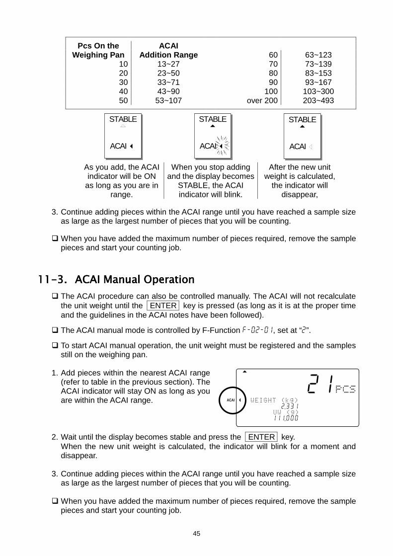
Pcs On the ACAIWeighing Pan Addition Range 60 63~123
10 13~27 70 73~13920 23~50 80 83~15330 33~71 90 93~16740 43~90 100 103~30050 53~107 over 200 203~493
As you add, the ACAIindicator will be ON
as long as you are inrange.
When you stop addingand the display becomes
STABLE, the ACAIindicator will blink.
After the new unitweight is calculated,
the indicator willdisappear,
3. Continue adding pieces within the ACAI range until you have reached a sample sizeas large as the largest number of pieces that you will be counting.
When you have added the maximum number of pieces required, remove the samplepieces and start your counting job.
11-3.11-3.11-3.11-3. ACAI Manual OperationACAI Manual OperationACAI Manual OperationACAI Manual Operation The ACAI procedure can also be controlled manually. The ACAI will not recalculate
the unit weight until the ENTER key is pressed (as long as it is at the proper timeand the guidelines in the ACAI notes have been followed).
The ACAI manual mode is controlled by F-Function f-02-01, set at “2”.
To start ACAI manual operation, the unit weight must be registered and the samplesstill on the weighing pan.
1. Add pieces within the nearest ACAI range(refer to table in the previous section). TheACAI indicator will stay ON as long as youare within the ACAI range.
2. Wait until the display becomes stable and press the ENTER key.When the new unit weight is calculated, the indicator will blink for a moment anddisappear.
3. Continue adding pieces within the ACAI range until you have reached a sample sizeas large as the largest number of pieces that you will be counting.
When you have added the maximum number of pieces required, remove the samplepieces and start your counting job.
STABLE
ACAI
STABLE
ACAI
STABLE
ACAI
8888821
A
12134567892 .331
12341567111 .000
ACAI
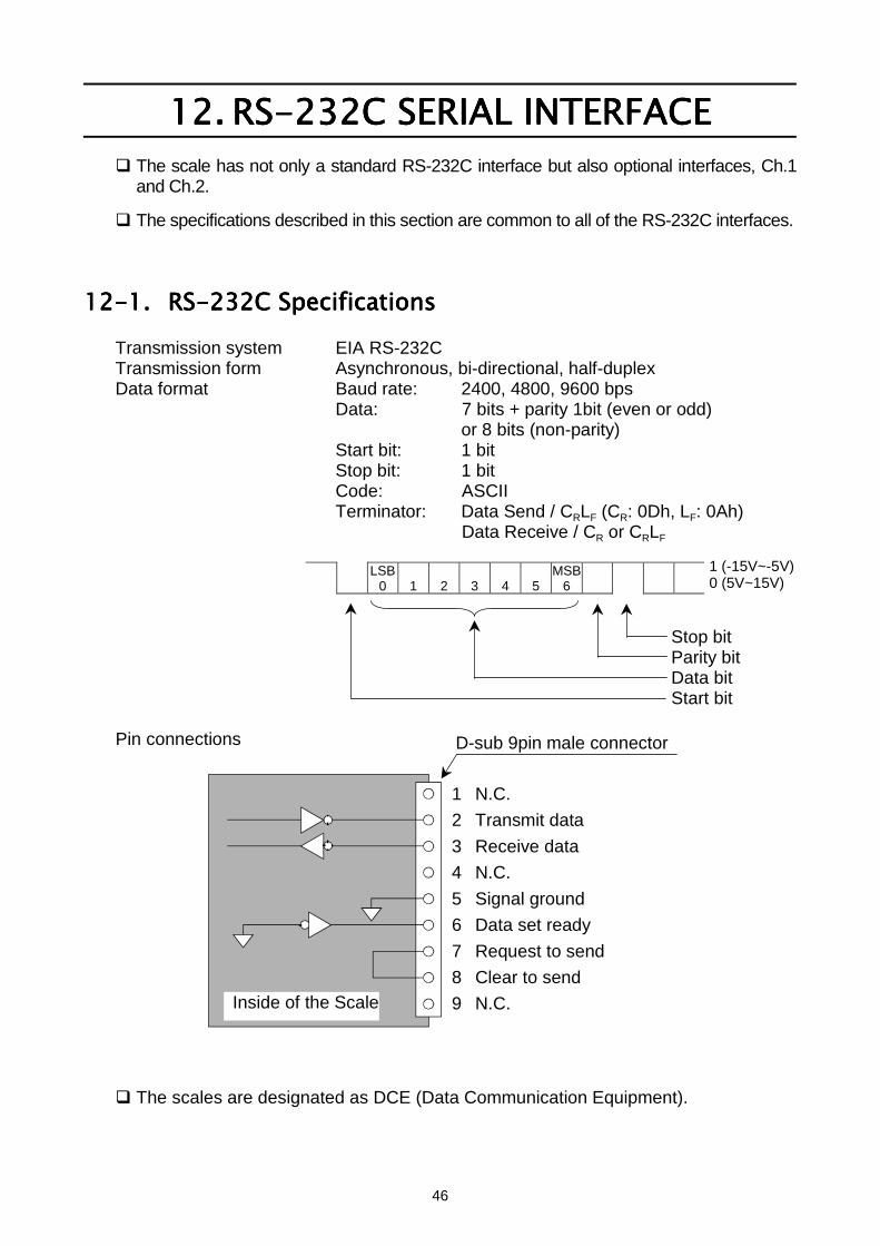
46
12.12.12.12. RS-232C SERIAL INTERFACERS-232C SERIAL INTERFACERS-232C SERIAL INTERFACERS-232C SERIAL INTERFACE The scale has not only a standard RS-232C interface but also optional interfaces, Ch.1
and Ch.2.
The specifications described in this section are common to all of the RS-232C interfaces.
12-1.12-1.12-1.12-1. RS-232C SpecificationsRS-232C SpecificationsRS-232C SpecificationsRS-232C SpecificationsTransmission system EIA RS-232CTransmission form Asynchronous, bi-directional, half-duplexData format Baud rate: 2400, 4800, 9600 bps
Data: 7 bits + parity 1bit (even or odd)or 8 bits (non-parity)
Start bit: 1 bitStop bit: 1 bitCode: ASCIITerminator: Data Send / CRLF (CR: 0Dh, LF: 0Ah)
Data Receive / CR or CRLF
LSB0 1 2 3 4 5
MSB6
Stop bitParity bitData bitStart bit
Pin connections
The scales are designated as DCE (Data Communication Equipment).
1 (-15V~-5V)0 (5V~15V)
D-sub 9pin male connector
1 N.C.2 Transmit data3 Receive data4 N.C.5 Signal ground6 Data set ready7 Request to send8 Clear to send9 N.C. Inside of the Scale
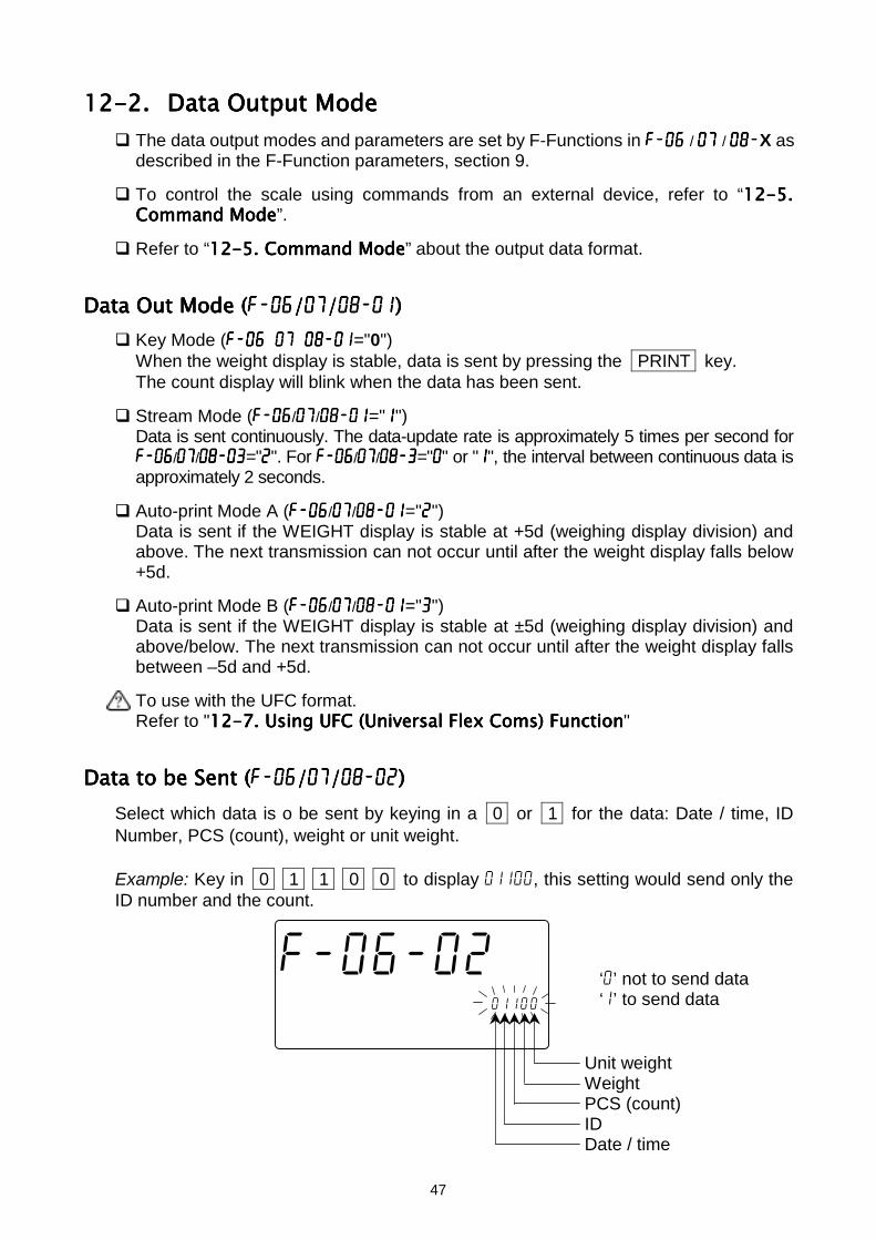
47
12-2.12-2.12-2.12-2. Data Output ModeData Output ModeData Output ModeData Output Mode The data output modes and parameters are set by F-Functions in f-06 f-06 f-06 f-06 / 07 07 07 07 / 08-08-08-08-X as
described in the F-Function parameters, section 9.
To control the scale using commands from an external device, refer to “12-512-512-512-5....Command ModeCommand ModeCommand ModeCommand Mode”.
Refer to “12-512-512-512-5. Command Mode. Command Mode. Command Mode. Command Mode” about the output data format.
Data Data Data Data Out Mode (Out Mode (Out Mode (Out Mode (f-06f-06f-06f-06////07070707////08-0108-0108-0108-01)))) Key Mode (f-06/07/08-01f-06/07/08-01f-06/07/08-01f-06/07/08-01="0")
When the weight display is stable, data is sent by pressing the PRINT key.The count display will blink when the data has been sent.
Stream Mode (f-06f-06f-06f-06/07070707/08-0108-0108-0108-01="1111")Data is sent continuously. The data-update rate is approximately 5 times per second forf-06f-06f-06f-06/07070707/08-0308-0308-0308-03="2222". For f-06f-06f-06f-06/07070707/08-308-308-308-3="0000" or "1111", the interval between continuous data isapproximately 2 seconds.
Auto-print Mode A (f-06f-06f-06f-06/07070707/08-0108-0108-0108-01="2222")Data is sent if the WEIGHT display is stable at +5d (weighing display division) andabove. The next transmission can not occur until after the weight display falls below+5d.
Auto-print Mode B (f-06f-06f-06f-06/07070707/08-0108-0108-0108-01="3333")Data is sent if the WEIGHT display is stable at ±5d (weighing display division) andabove/below. The next transmission can not occur until after the weight display fallsbetween –5d and +5d.
To use with the UFC format.Refer to "12-712-712-712-7. . . . Using UFC (Universal Flex Coms) FunctionUsing UFC (Universal Flex Coms) FunctionUsing UFC (Universal Flex Coms) FunctionUsing UFC (Universal Flex Coms) Function"
Data to be Data to be Data to be Data to be Sent (Sent (Sent (Sent (f-06f-06f-06f-06////07070707////08-0208-0208-0208-02))))Select which data is o be sent by keying in a 0 or 1 for the data: Date / time, IDNumber, PCS (count), weight or unit weight.
Example: Key in 0 1 1 0 0 to display 01100, this setting would send only theID number and the count.
Unit weightWeightPCS (count)IDDate / time
f-06-02
12345678C000045678id-001100
12345670 .0000045678901234567
‘0’ not to send data‘1’ to send data
48
Data Format (Data Format (Data Format (Data Format (f-06f-06f-06f-06////07070707////08-0308-0308-0308-03)))) Format for AD-8121 MODE 1 or 2. (f-06f-06f-06f-06/07070707/08-0308-0308-0308-03="0000")
Format for AD-8121 MODE 3. (f-06f-06f-06f-06/07070707/08-0308-0308-0308-03="1111")
Format for general apparatuses, computers, etc. (f-06f-06f-06f-06/07070707/08-0308-0308-0308-03="2222")
Baud Rate (Baud Rate (Baud Rate (Baud Rate (f-06f-06f-06f-06////07070707////08-0408-0408-0408-04))))Select the baud rate according to the device to be connected. 2400 bps (f-06f-06f-06f-06/07070707/08-0408-0408-0408-04="0000") Select 2400 bps to connect with an AD-8121. 4800 bps (f-06f-06f-06f-06/07070707/08-0408-0408-0408-04="1111") 9600 bps (f-06f-06f-06f-06/07070707/08-0408-0408-0408-04="2222")
12-3.12-3.12-3.12-3. Connecting the AD-8121 Printer / MODE 1 or MODE 2Connecting the AD-8121 Printer / MODE 1 or MODE 2Connecting the AD-8121 Printer / MODE 1 or MODE 2Connecting the AD-8121 Printer / MODE 1 or MODE 2 When using the AD-8121 printer (MODE1 or MODE 2), you will be able to get data:
Number of data items, total, maximum, minimum, mean value, range of data(max. - min. data) and standard deviation.
When using the AD-8121 with MODE 2, set f-06/07/08-02 to print pcs (count) dataonly or weight data only.
To print date and time, use the AD-8121’s calendar / clock function and setf-06/07/08-2 to print pcs (count) data only or weight data only.
Print Operations SettingsPrint Operations SettingsPrint Operations SettingsPrint Operations SettingsPrint By: F-Function f-06/07/08-01 Printer MODE
FC PRINT key 0 MODE 1Auto Print 2 or 3 MODE 1
Printer DATA key 1 MODE 2
Example of Example of Example of Example of f-06f-06f-06f-06////07070707////08-0208-0208-0208-02 settings settings settings settings To print pcs (count) data only: set f-06f-06f-06f-06/07070707/08-0208-0208-0208-02 at "00100"
To print weight data only: set f-06f-06f-06f-06/07070707/08-0208-0208-0208-02 at "00010"
To print pcs (count) and weight data: set f-06f-06f-06f-06/07070707/08-0208-0208-0208-02 at "00110"
To print pcs, weight and Unit Weight data: set f-06f-06f-06f-06/07070707/08-0208-0208-0208-02 at "00111"
To print total data (accumulated by the M+ key), press the TOTAL key so theCount display shows the total, then press the PRINT key.
If you are using the AD-8121’s statistic functions, then set f-06f-06f-06f-06/07070707/08-0208-0208-0208-02 at "001#0"(# = 0 or 1) for pcs (count) data or "00010" for weight data.
MODE 1 and 2 of the AD-8121 can not print ID numbers.
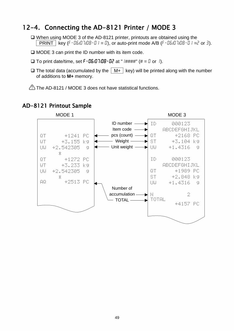
49
12-4.12-4.12-4.12-4. Connecting the AD-8121 Printer / MODE 3Connecting the AD-8121 Printer / MODE 3Connecting the AD-8121 Printer / MODE 3Connecting the AD-8121 Printer / MODE 3 When using MODE 3 of the AD-8121 printer, printouts are obtained using the
PRINT key (f-06/07/08-01 = 0), or auto-print mode A/B (f-06/07/08-01 =2 or 3).
MODE 3 can print the ID number with its item code.
To print date/time, set f-06f-06f-06f-06/07070707/08-0208-0208-0208-02 at "1####" (# = 0 or 1).
The total data (accumulated by the M+ key) will be printed along with the numberof additions to M+ memory.
The AD-8121 / MODE 3 does not have statistical functions.
AD-8121 Printout SampleAD-8121 Printout SampleAD-8121 Printout SampleAD-8121 Printout SampleMODE 1 MODE 3
ID numberItem codepcs (count)
WeightUnit weight
Number ofaccumulation
TOTAL
!
" "
!
#
$
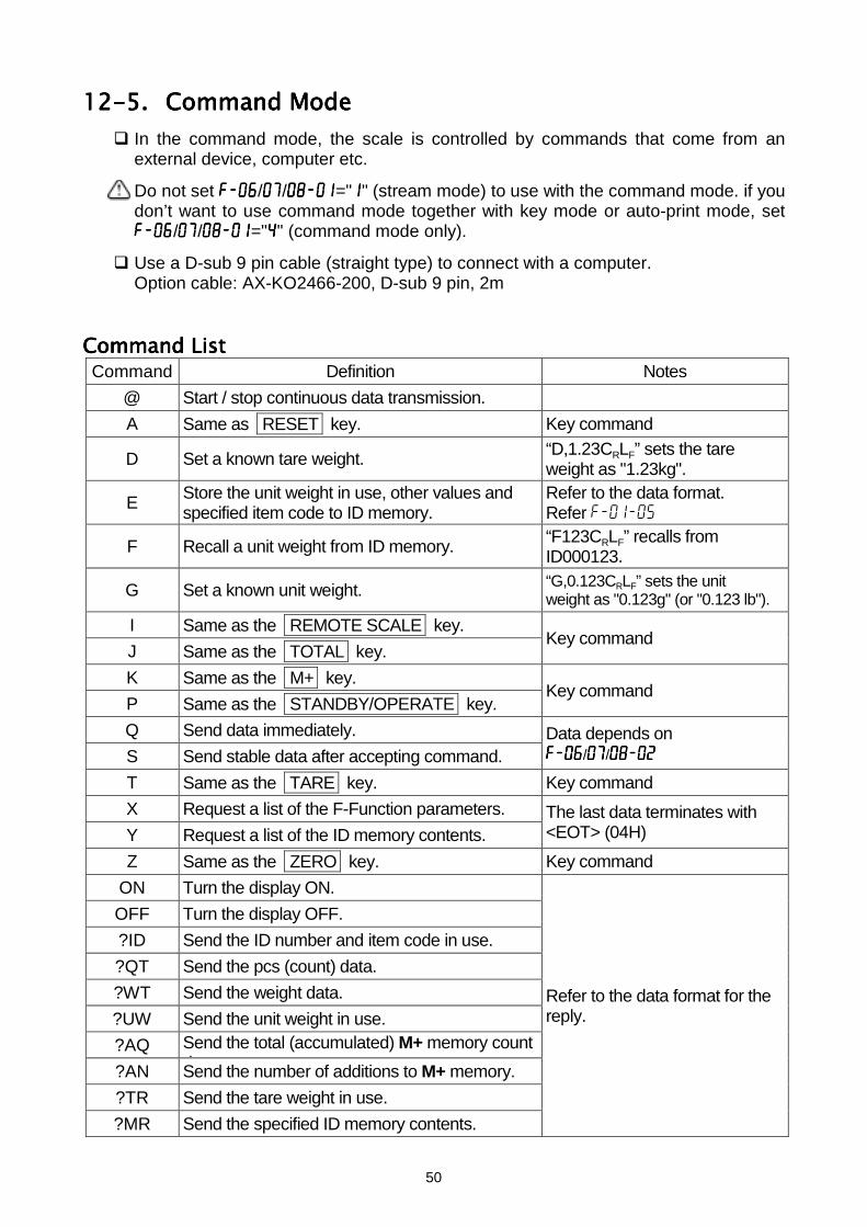
50
12-5.12-5.12-5.12-5. Command ModeCommand ModeCommand ModeCommand Mode In the command mode, the scale is controlled by commands that come from an
external device, computer etc.
Do not set f-06f-06f-06f-06/07070707/08-0108-0108-0108-01="1111" (stream mode) to use with the command mode. if youdon’t want to use command mode together with key mode or auto-print mode, setf-06f-06f-06f-06/07070707/08-0108-0108-0108-01="4444" (command mode only).
Use a D-sub 9 pin cable (straight type) to connect with a computer.Option cable: AX-KO2466-200, D-sub 9 pin, 2m
Command ListCommand ListCommand ListCommand ListCommand Definition Notes
@ Start / stop continuous data transmission.A Same as RESET key. Key command
D Set a known tare weight. “D,1.23CRLF” sets the tareweight as "1.23kg".
E Store the unit weight in use, other values andspecified item code to ID memory.
Refer to the data format.Refer f-01-05
F Recall a unit weight from ID memory. “F123CRLF” recalls fromID000123.
G Set a known unit weight. “G,0.123CRLF” sets the unitweight as "0.123g" (or "0.123 lb").
I Same as the REMOTE SCALE key.J Same as the TOTAL key.
Key command
K Same as the M+ key.P Same as the STANDBY/OPERATE key.
Key command
Q Send data immediately.S Send stable data after accepting command.
Data depends onf-06f-06f-06f-06/07070707/08-0208-0208-0208-02
T Same as the TARE key. Key commandX Request a list of the F-Function parameters.Y Request a list of the ID memory contents.
The last data terminates with<EOT> (04H)
Z Same as the ZERO key. Key commandON Turn the display ON.OFF Turn the display OFF.?ID Send the ID number and item code in use.?QT Send the pcs (count) data.?WT Send the weight data.?UW Send the unit weight in use.?AQ Send the total (accumulated) M+ memory count
d t?AN Send the number of additions to M+ memory.?TR Send the tare weight in use.?MR Send the specified ID memory contents.
Refer to the data format for thereply.
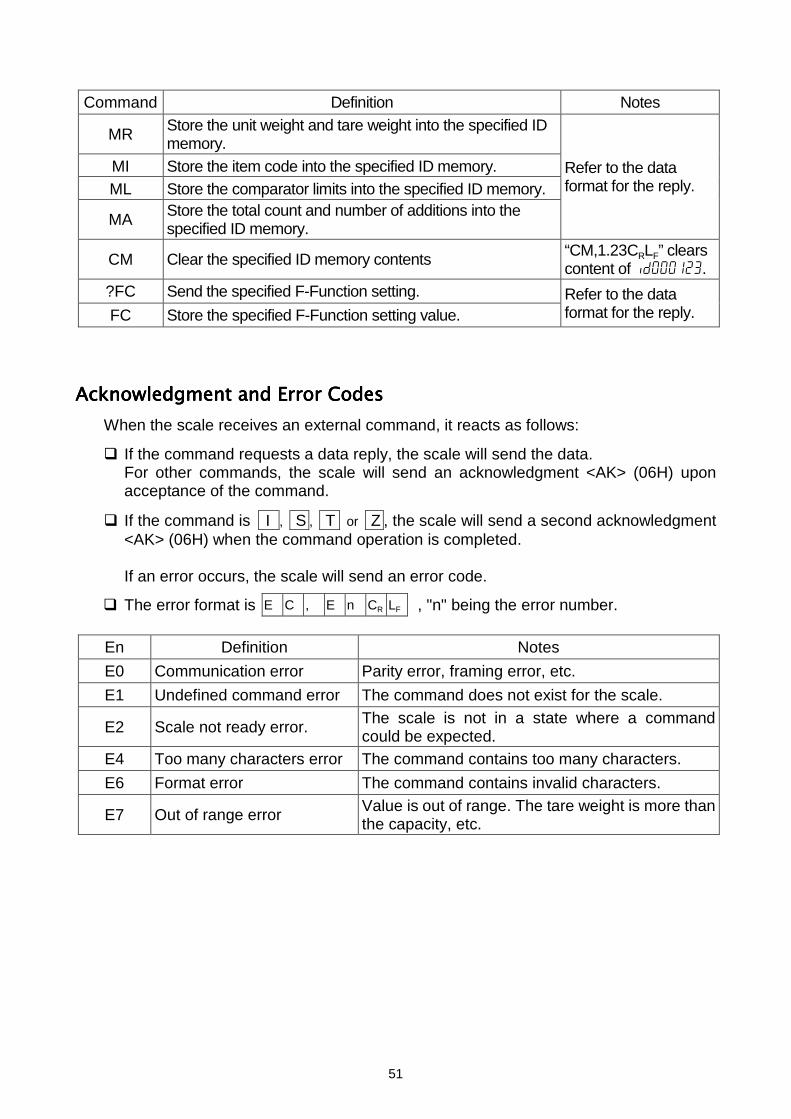
51
Command Definition Notes
MR Store the unit weight and tare weight into the specified IDmemory.
MI Store the item code into the specified ID memory.ML Store the comparator limits into the specified ID memory.
MA Store the total count and number of additions into thespecified ID memory.
Refer to the dataformat for the reply.
CM Clear the specified ID memory contents “CM,1.23CRLF” clearscontent of id000123.
?FC Send the specified F-Function setting.FC Store the specified F-Function setting value.
Refer to the dataformat for the reply.
Acknowledgment and Error CodesAcknowledgment and Error CodesAcknowledgment and Error CodesAcknowledgment and Error CodesWhen the scale receives an external command, it reacts as follows:
If the command requests a data reply, the scale will send the data.For other commands, the scale will send an acknowledgment <AK> (06H) uponacceptance of the command.
If the command is I , S , T or Z , the scale will send a second acknowledgment<AK> (06H) when the command operation is completed.
If an error occurs, the scale will send an error code.
The error format is E C , E n CR LF , "n" being the error number.
En Definition NotesE0 Communication error Parity error, framing error, etc.E1 Undefined command error The command does not exist for the scale.
E2 Scale not ready error. The scale is not in a state where a commandcould be expected.
E4 Too many characters error The command contains too many characters.E6 Format error The command contains invalid characters.
E7 Out of range error Value is out of range. The tare weight is more thanthe capacity, etc.
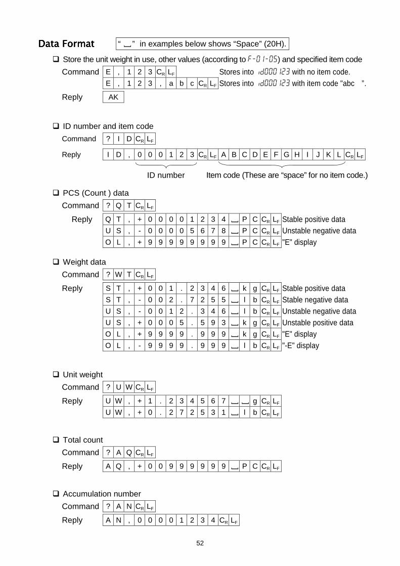
52
Data FormatData FormatData FormatData Format Store the unit weight in use, other values (according to f-01-05) and specified item code
Command E , 1 2 3 CR LF Stores into id000123 with no item code.E , 1 2 3 , a b c CR LF Stores into id000123 with item code "abc ”.
Reply AK
ID number and item codeCommand ? I D CR LF
Reply I D , 0 0 0 1 2 3 CR LF A B C D E F G H I J K L CR LF
PCS (Count ) dataCommand ? Q T CR LF
Reply Q T , + 0 0 0 0 1 2 3 4 [ P C CR LF Stable positive dataU S , - 0 0 0 0 5 6 7 8 [ P C CR LF Unstable negative dataO L , + 9 9 9 9 9 9 9 9 [ P C CR LF "E" display
Weight dataCommand ? W T CR LF
Reply S T , + 0 0 1 . 2 3 4 6 [ k g CR LF Stable positive dataS T , - 0 0 2 . 7 2 5 5 [ l b CR LF Stable negative dataU S , - 0 0 1 2 . 3 4 6 [ l b CR LF Unstable negative dataU S , + 0 0 0 5 . 5 9 3 [ k g CR LF Unstable positive dataO L , + 9 9 9 9 . 9 9 9 [ k g CR LF "E" displayO L , - 9 9 9 9 . 9 9 9 [ l b CR LF "-E" display
Unit weightCommand ? U W CR LF
Reply U W , + 1 . 2 3 4 5 6 7 [ [ g CR LF
U W , + 0 . 2 7 2 5 3 1 [ l b CR LF
Total countCommand ? A Q CR LF
Reply A Q , + 0 0 9 9 9 9 9 9 [ P C CR LF
Accumulation numberCommand ? A N CR LF
Reply A N , 0 0 0 0 1 2 3 4 CR LF
ID number Item code (These are “space” for no item code.)
“ [ ” in examples below shows “Space” (20H).
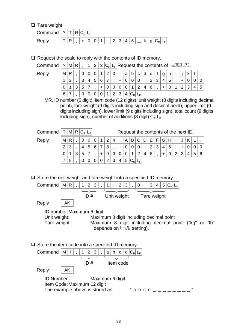
53
Tare weightCommand ? T R CR LF
Reply T R , + 0 0 1 . 2 3 4 6 [ k g CR LF
Request the scale to reply with the contents of ID memory.Command ? M R , 1 2 3 CR LF Request the contents of id000123.
Reply M R , 0 0 0 1 2 3 , a b c d e f g h i j k l ,1 2 . 3 4 5 6 7 , + 0 0 0 . 2 3 4 5 , + 0 0 00 1 3 5 7 , + 0 0 0 0 1 2 4 6 , + 0 1 2 3 4 56 7 , 0 0 0 0 1 2 3 4 CR LF
MR, ID number (6 digit), item code (12 digits), unit weight (8 digits including decimalpoint), tare weight (9 digits including sign and decimal point), upper limit (9digits including sign), lower limit (9 digits including sign), total count (9 digitsincluding sign), number of additions (8 digit) CR LF .
Command ? M R CR LF Request the contents of the next ID.Reply M R , 0 0 0 1 2 4 , A B C D E F G H I J K L ,
2 3 . 4 5 6 7 8 , + 0 0 0 . 2 3 4 5 , + 0 0 00 1 3 5 7 , + 0 0 0 0 1 2 4 6 , + 0 2 3 4 5 67 8 , 0 0 0 0 2 3 4 5 CR LF
Store the unit weight and tare weight into a specified ID memory.Command M R , 1 2 3 , 1 . 2 3 , 0 . 3 4 5 CR LF
Reply AK
ID number:Maximum 6 digitUnit weight: Maximum 8 digit including decimal pointTare weight: Maximum 8 digit including decimal point ("kg" or "lb"
depends on f-00 setting).
Store the item code into a specified ID memory.Command M I , 1 2 3 , a b c d CR LF
Reply AK
ID Number: Maximum 6 digitItem Code:Maximum 12 digitThe example above is stored as
ID # Unit weight Tare weight
ID # Item code
“ a b c d [ [ [ [ [ [ [ [ ”
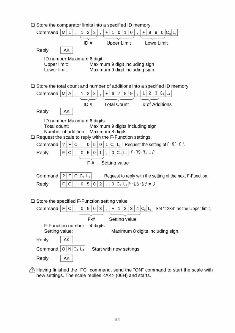
54
Store the comparator limits into a specified ID memory.Command M L , 1 2 3 , + 1 0 1 0 , + 9 9 0 CR LF
Reply AK
ID number:Maximum 6 digitUpper limit: Maximum 9 digit including signLower limit: Maximum 9 digit including sign
Store the total count and number of additions into a specified ID memory.Command M A , 1 2 3 , + 6 7 8 9 , 1 2 3 CR LF
Reply AK
ID number:Maximum 6 digitsTotal count: Maximum 9 digits including signNumber of addition: Maximum 8 digits
Request the scale to reply with the F-Function settings.Command ? F C , 0 5 0 1 CR LF Request the setting of f-05-01.Reply F C , 0 5 0 1 , 0 CR LF f-05-01 = 0
Command ? F C CR LF Request to reply with the setting of the next F-Function.
Reply F C , 0 5 0 2 , 0 CR LF f-05-02 = 0
Store the specified F-Function setting valueCommand F C , 0 5 0 3 , + 1 2 3 4 CR LF Set “1234” as the Upper limit.
F-Function number: 4 digitsSetting value: Maximum 8 digits including sign.
Reply AK
Command O N CR LF Start with new settings.
Reply AK
Having finished the "FC" command, send the "ON" command to start the scale withnew settings. The scale replies <AK> (06H) and starts.
ID # Upper Limit Lowe Limit
ID # Total Count # of Additions
F-# Setting value
F-# Setting value
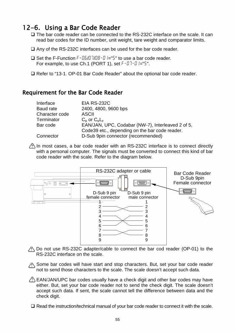
55
12-6.12-6.12-6.12-6. Using a Bar Code ReaderUsing a Bar Code ReaderUsing a Bar Code ReaderUsing a Bar Code Reader The bar code reader can be connected to the RS-232C interface on the scale. It can
read bar codes for the ID number, unit weight, tare weight and comparator limits.
Any of the RS-232C interfaces can be used for the bar code reader.
Set the F-Function f-06/07/08-01="5" to use a bar code reader.For example, to use Ch.1 (PORT 1), set f-07-01="5".
Refer to “13-1. OP-01 Bar Code Reader” about the optional bar code reader.
Requirement for the Bar Code ReaderRequirement for the Bar Code ReaderRequirement for the Bar Code ReaderRequirement for the Bar Code ReaderInterface EIA RS-232CBaud rate 2400, 4800, 9600 bpsCharacter code ASCIITerminator CR or CRLFBar code EAN/JAN, UPC, Codabar (NW-7), Interleaved 2 of 5,
Code39 etc., depending on the bar code reader.Connector D-Sub 9pin connector (recommended)
In most cases, a bar code reader with an RS-232C interface is to connect directlywith a personal computer. The signals must be converted to connect this kind of barcode reader with the scale. Refer to the diagram below.
Do not use RS-232C adapter/cable to connect the bar cod reader (OP-01) to theRS-232C interface on the scale.
Some bar codes will have start and stop characters. But, set your bar code readernot to send those characters to the scale. The scale doesn’t accept such data.
EAN/JAN/UPC bar codes usually have a check digit and other bar codes may haveeither. But, set your bar code reader not to send the check digit. The scale doesn’taccept such data. If sent, the scale cannot tell the difference between data and thecheck digit.
Read the instruction/technical manual of your bar code reader to connect it with the scale.
RS-232C adapter or cable
D-Sub 9 pin D-Sub 9 pin female connector male connector
1 12 23 34 45 56 67 78 89 9
Bar Code ReaderD-Sub 9pin
Female connector
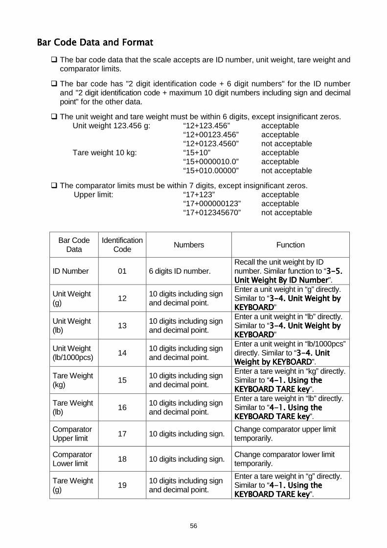
56
Bar Code Data and FormatBar Code Data and FormatBar Code Data and FormatBar Code Data and Format The bar code data that the scale accepts are ID number, unit weight, tare weight and
comparator limits.
The bar code has "2 digit identification code + 6 digit numbers" for the ID numberand "2 digit identification code + maximum 10 digit numbers including sign and decimalpoint" for the other data.
The unit weight and tare weight must be within 6 digits, except insignificant zeros.Unit weight 123.456 g: “12+123.456” acceptable
“12+00123.456” acceptable“12+0123.4560” not acceptable
Tare weight 10 kg: “15+10” acceptable“15+0000010.0” acceptable“15+010.00000” not acceptable
The comparator limits must be within 7 digits, except insignificant zeros.Upper limit: “17+123” acceptable
“17+000000123” acceptable“17+012345670” not acceptable
Bar CodeData
IdentificationCode Numbers Function
ID Number 01 6 digits ID number.Recall the unit weight by IDnumber. Similar function to “3-53-53-53-5....Unit Weight By ID NumberUnit Weight By ID NumberUnit Weight By ID NumberUnit Weight By ID Number”.
Unit Weight(g) 12 10 digits including sign
and decimal point.
Enter a unit weight in “g” directly.Similar to “3-43-43-43-4. Unit Weight by. Unit Weight by. Unit Weight by. Unit Weight byKEYBOARDKEYBOARDKEYBOARDKEYBOARD”
Unit Weight(lb) 13 10 digits including sign
and decimal point.
Enter a unit weight in “lb” directly.Similar to “3-43-43-43-4. Unit Weight by. Unit Weight by. Unit Weight by. Unit Weight byKEYBOARDKEYBOARDKEYBOARDKEYBOARD”
Unit Weight(lb/1000pcs) 14 10 digits including sign
and decimal point.
Enter a unit weight in “lb/1000pcs”directly. Similar to “3-43-43-43-4. Unit. Unit. Unit. UnitWeight by KEYBOARDWeight by KEYBOARDWeight by KEYBOARDWeight by KEYBOARD”.
Tare Weight(kg) 15 10 digits including sign
and decimal point.
Enter a tare weight in “kg” directly.Similar to “4-14-14-14-1. Using the. Using the. Using the. Using theKEYBOARD TARE keyKEYBOARD TARE keyKEYBOARD TARE keyKEYBOARD TARE key”.
Tare Weight(lb) 16 10 digits including sign
and decimal point.
Enter a tare weight in “lb” directly.Similar to “4-14-14-14-1. Using the. Using the. Using the. Using theKEYBOARD TARE keyKEYBOARD TARE keyKEYBOARD TARE keyKEYBOARD TARE key”.
ComparatorUpper limit 17 10 digits including sign. Change comparator upper limit
temporarily.
ComparatorLower limit 18 10 digits including sign. Change comparator lower limit
temporarily.
Tare Weight(g) 19 10 digits including sign
and decimal point.
Enter a tare weight in “g” directly.Similar to “4-14-14-14-1. Using the. Using the. Using the. Using theKEYBOARD TARE keyKEYBOARD TARE keyKEYBOARD TARE keyKEYBOARD TARE key”.
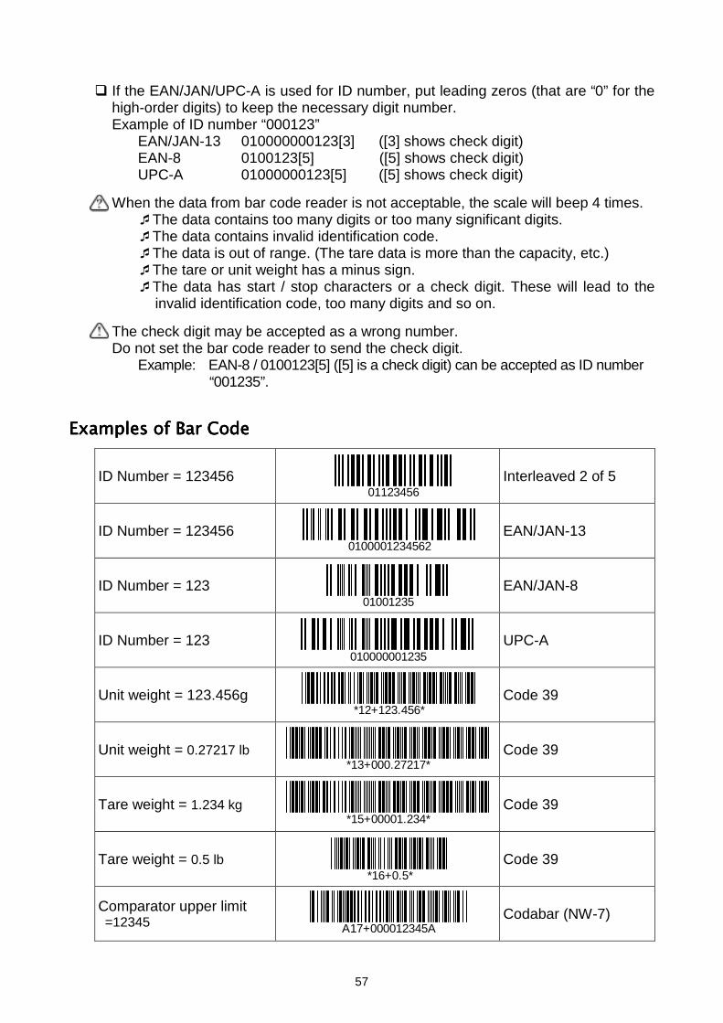
57
If the EAN/JAN/UPC-A is used for ID number, put leading zeros (that are “0” for thehigh-order digits) to keep the necessary digit number.Example of ID number “000123”
EAN/JAN-13 010000000123[3] ([3] shows check digit)EAN-8 0100123[5] ([5] shows check digit)UPC-A 01000000123[5] ([5] shows check digit)
When the data from bar code reader is not acceptable, the scale will beep 4 times.The data contains too many digits or too many significant digits.The data contains invalid identification code.The data is out of range. (The tare data is more than the capacity, etc.)The tare or unit weight has a minus sign.The data has start / stop characters or a check digit. These will lead to the
invalid identification code, too many digits and so on.
The check digit may be accepted as a wrong number.Do not set the bar code reader to send the check digit.
Example: EAN-8 / 0100123[5] ([5] is a check digit) can be accepted as ID number“001235”.
Examples of Bar CodeExamples of Bar CodeExamples of Bar CodeExamples of Bar Code
ID Number = 123456 Interleaved 2 of 5
ID Number = 123456 EAN/JAN-13
ID Number = 123 EAN/JAN-8
ID Number = 123 UPC-A
Unit weight = 123.456g Code 39
Unit weight = 0.27217 lb Code 39
Tare weight = 1.234 kg Code 39
Tare weight = 0.5 lb Code 39
Comparator upper limit =12345 Codabar (NW-7)
0100001234562
01001235
A17+000012345A
*16+0.5*
*15+00001.234*
*13+000.27217*
*12+123.456*
010000001235
01123456
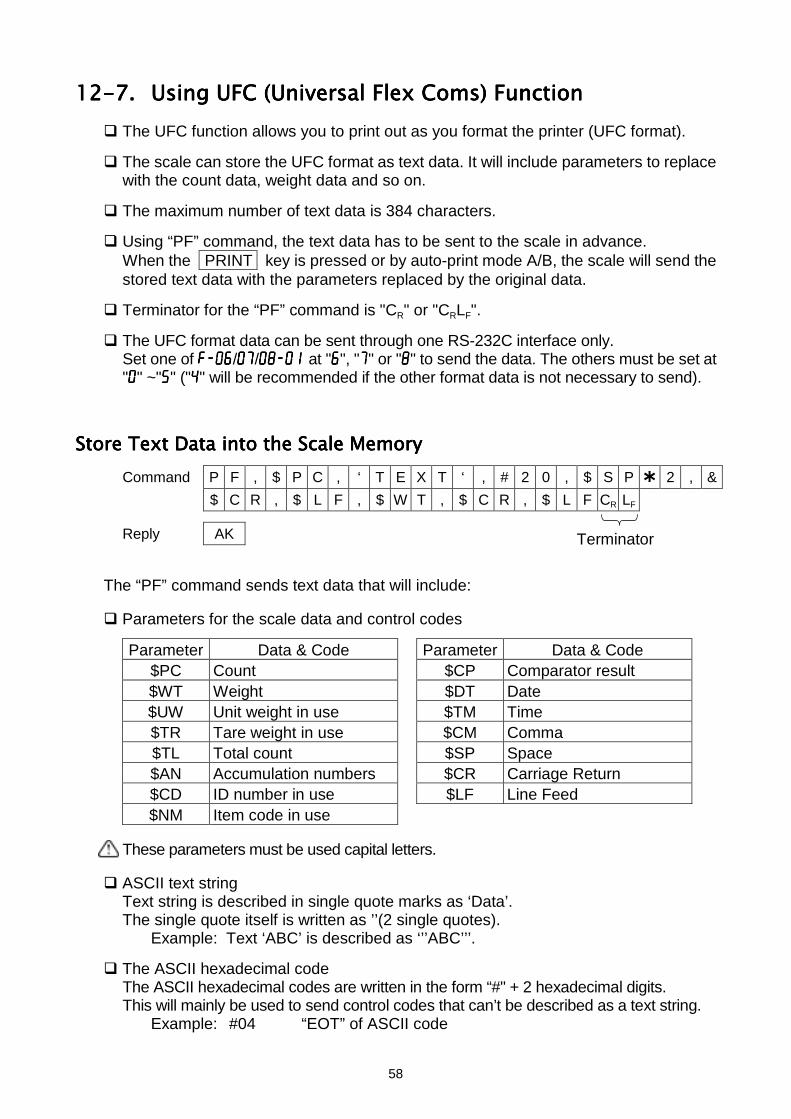
58
12-7.12-7.12-7.12-7. Using UFC (Universal Flex Coms) FunctionUsing UFC (Universal Flex Coms) FunctionUsing UFC (Universal Flex Coms) FunctionUsing UFC (Universal Flex Coms) Function The UFC function allows you to print out as you format the printer (UFC format).
The scale can store the UFC format as text data. It will include parameters to replacewith the count data, weight data and so on.
The maximum number of text data is 384 characters.
Using “PF” command, the text data has to be sent to the scale in advance.When the PRINT key is pressed or by auto-print mode A/B, the scale will send thestored text data with the parameters replaced by the original data.
Terminator for the “PF” command is "CR" or "CRLF".
The UFC format data can be sent through one RS-232C interface only.Set one of f-06f-06f-06f-06/07070707/08-01 08-01 08-01 08-01 at "6666", "7777" or "8888" to send the data. The others must be set at"0000" ~"5555" ("4444" will be recommended if the other format data is not necessary to send).
Store Text Data into the Scale MemoryStore Text Data into the Scale MemoryStore Text Data into the Scale MemoryStore Text Data into the Scale MemoryCommand P F , $ P C , ‘ T E X T ‘ , # 2 0 , $ S P 2 , &
$ C R , $ L F , $ W T , $ C R , $ L F CR LF
Reply AK
The “PF” command sends text data that will include:
Parameters for the scale data and control codes
Parameter Data & Code Parameter Data & Code$PC Count $CP Comparator result$WT Weight $DT Date$UW Unit weight in use $TM Time$TR Tare weight in use $CM Comma$TL Total count $SP Space$AN Accumulation numbers $CR Carriage Return$CD ID number in use $LF Line Feed$NM Item code in use
These parameters must be used capital letters.
ASCII text stringText string is described in single quote marks as ‘Data’.The single quote itself is written as ’’(2 single quotes).
Example: Text ‘ABC’ is described as ‘’’ABC’’’.
The ASCII hexadecimal codeThe ASCII hexadecimal codes are written in the form “#" + 2 hexadecimal digits.This will mainly be used to send control codes that can’t be described as a text string.
Example: #04 “EOT” of ASCII code
Terminator
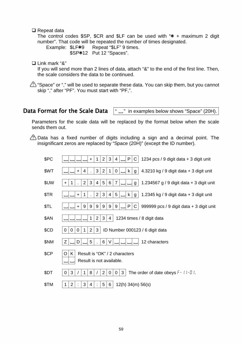
59
Repeat dataThe control codes $SP, $CR and $LF can be used with “ + maximum 2 digitnumber”. That code will be repeated the number of times designated.
Example: $LF 9 Repeat “$LF” 9 times.$SP 12 Put 12 “Spaces”.
Link mark “&”If you will send more than 2 lines of data, attach “&” to the end of the first line. Then,the scale considers the data to be continued.
“Space” or “,” will be used to separate these data. You can skip them, but you cannotskip “,” after “PF”. You must start with “PF,”.
Data Format for the Scale DataData Format for the Scale DataData Format for the Scale DataData Format for the Scale DataParameters for the scale data will be replaced by the format below when the scalesends them out.
Data has a fixed number of digits including a sign and a decimal point. Theinsignificant zeros are replaced by “Space (20H)” (except the ID number).
$PC [ [ [ [ + 1 2 3 4 [ P C 1234 pcs / 9 digit data + 3 digit unit
$WT [ [ + 4 . 3 2 1 0 [ k g 4.3210 kg / 9 digit data + 3 digit unit
$UW + 1 . 2 3 4 5 6 7 [ [ g 1.234567 g / 9 digit data + 3 digit unit
$TR [ [ + 1 . 2 3 4 5 [ k g 1.2345 kg / 9 digit data + 3 digit unit
$TL [ [ + 9 9 9 9 9 9 [ P C 999999 pcs / 9 digit data + 3 digit unit
$AN [ [ [ [ 1 2 3 4 1234 times / 8 digit data
$CD 0 0 0 1 2 3 ID Number 000123 / 6 digit data
$NM Z [ D [ 5 . 6 V [ [ [ [ 12 characters
$CP O K Result is “OK” / 2 characters
[ [ Result is not available.
$DT 0 3 / 1 8 / 2 0 0 3 The order of date obeys f-11-01.
$TM 1 2 : 3 4 : 5 6 12(h) 34(m) 56(s)
“ [ ” in examples below shows “Space” (20H).
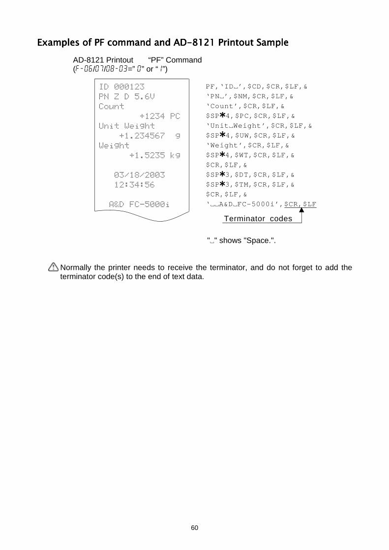
60
PF,‘ID~’,$CD,$CR,$LF,&
‘PN~’,$NM,$CR,$LF,&
‘Count’,$CR,$LF,&
$SP 4,$PC,$CR,$LF,&
‘Unit~Weight’,$CR,$LF,&
$SP 4,$UW,$CR,$LF,&
‘Weight’,$CR,$LF,&
$SP 4,$WT,$CR,$LF,&
$CR,$LF,&
$SP 3,$DT,$CR,$LF,&
$SP 3,$TM,$CR,$LF,&
$CR,$LF,&
‘~~A&D~FC-5000i’,$CR,$LF
Terminator codes
Examples of PF command and AD-8121 Printout SampleExamples of PF command and AD-8121 Printout SampleExamples of PF command and AD-8121 Printout SampleExamples of PF command and AD-8121 Printout SampleAD-8121 Printout “PF” Command(f-06/07/08-03=” 0” or “1”)
"~" shows "Space.".
Normally the printer needs to receive the terminator, and do not forget to add theterminator code(s) to the end of text data.
#% &
'()*
)+*,+-*
,+-*
. .
//
01 +
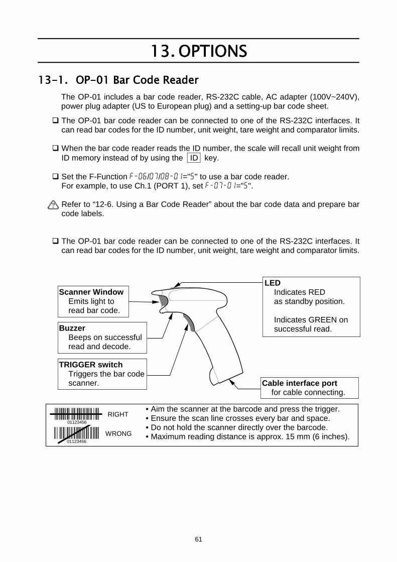
61
13.13.13.13. OPTIONSOPTIONSOPTIONSOPTIONS13-1.13-1.13-1.13-1. OP-01 Bar Code ReaderOP-01 Bar Code ReaderOP-01 Bar Code ReaderOP-01 Bar Code Reader
The OP-01 includes a bar code reader, RS-232C cable, AC adapter (100V~240V),power plug adapter (US to European plug) and a setting-up bar code sheet.
The OP-01 bar code reader can be connected to one of the RS-232C interfaces. Itcan read bar codes for the ID number, unit weight, tare weight and comparator limits.
When the bar code reader reads the ID number, the scale will recall unit weight fromID memory instead of by using the ID key.
Set the F-Function f-06/07/08-01="5" to use a bar code reader.For example, to use Ch.1 (PORT 1), set f-07-01="5".
Refer to “12-6. Using a Bar Code Reader” about the bar code data and prepare barcode labels.
The OP-01 bar code reader can be connected to one of the RS-232C interfaces. Itcan read bar codes for the ID number, unit weight, tare weight and comparator limits.
TRIGGER switchTriggers the bar codescanner.
BuzzerBeeps on successfulread and decode.
Cable interface portfor cable connecting.
Scanner WindowEmits light toread bar code.
LEDIndicates REDas standby position.
Indicates GREEN onsuccessful read.
• Aim the scanner at the barcode and press the trigger.• Ensure the scan line crosses every bar and space.• Do not hold the scanner directly over the barcode.• Maximum reading distance is approx. 15 mm (6 inches).WRONG
01123456
01123456RIGHT
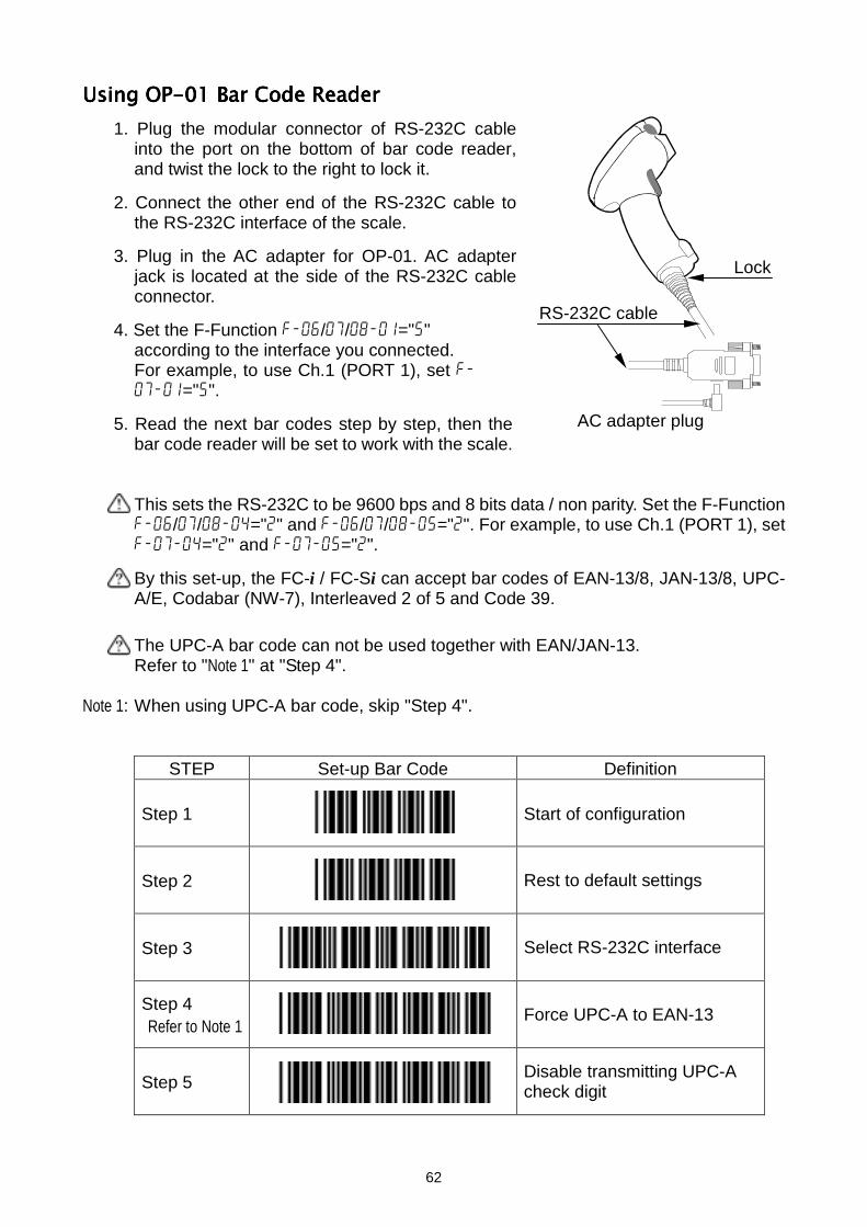
62
Using OP-01 Using OP-01 Using OP-01 Using OP-01 Bar Code ReaderBar Code ReaderBar Code ReaderBar Code Reader1. Plug the modular connector of RS-232C cable
into the port on the bottom of bar code reader,and twist the lock to the right to lock it.
2. Connect the other end of the RS-232C cable tothe RS-232C interface of the scale.
3. Plug in the AC adapter for OP-01. AC adapterjack is located at the side of the RS-232C cableconnector.
4. Set the F-Function f-06/07/08-01="5"according to the interface you connected.For example, to use Ch.1 (PORT 1), set f-07-01="5".
5. Read the next bar codes step by step, then thebar code reader will be set to work with the scale.
This sets the RS-232C to be 9600 bps and 8 bits data / non parity. Set the F-Functionf-06/07/08-04="2" and f-06/07/08-05="2". For example, to use Ch.1 (PORT 1), setf-07-04="2" and f-07-05="2".
By this set-up, the FC-i / FC-Si can accept bar codes of EAN-13/8, JAN-13/8, UPC-A/E, Codabar (NW-7), Interleaved 2 of 5 and Code 39.
The UPC-A bar code can not be used together with EAN/JAN-13.Refer to "Note 1" at "Step 4".
Note 1: When using UPC-A bar code, skip "Step 4".
STEP Set-up Bar Code Definition
Step 1 Start of configuration
Step 2 Rest to default settings
Step 3 Select RS-232C interface
Step 4Refer to Note 1 Force UPC-A to EAN-13
Step 5 Disable transmitting UPC-Acheck digit
Lock
RS-232C cable
AC adapter plug
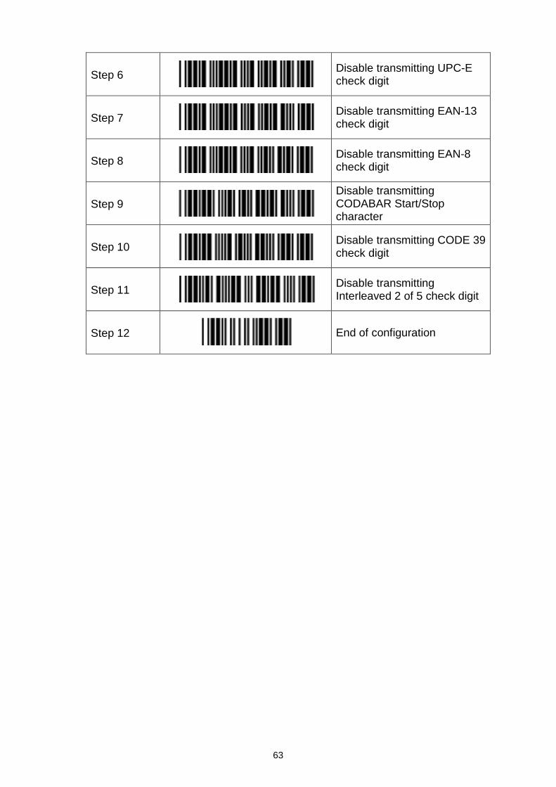
63
Step 6 Disable transmitting UPC-Echeck digit
Step 7 Disable transmitting EAN-13check digit
Step 8 Disable transmitting EAN-8check digit
Step 9Disable transmittingCODABAR Start/Stopcharacter
Step 10 Disable transmitting CODE 39check digit
Step 11 Disable transmittingInterleaved 2 of 5 check digit
Step 12 End of configuration
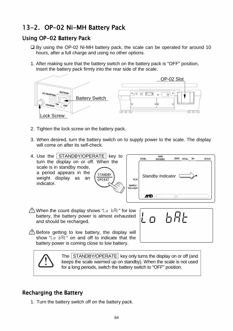
64
STABL
888888 .
123456789012345678901234567
123456789012345678901234567
ZERO TOTAL M+TARE
ENTERED SCALE
ACAI
SAMPLETOO LIGHT
OPERATSTANDBY Standby Indicator
lo bat
123456789012345678901210 .000
13-2.13-2.13-2.13-2. OP-02 Ni-MH Battery PackOP-02 Ni-MH Battery PackOP-02 Ni-MH Battery PackOP-02 Ni-MH Battery PackUsing OP-02 Battery PackUsing OP-02 Battery PackUsing OP-02 Battery PackUsing OP-02 Battery Pack
By using the OP-02 Ni-MH battery pack, the scale can be operated for around 10hours, after a full charge and using no other options.
1. After making sure that the battery switch on the battery pack is "OFF" position,insert the battery pack firmly into the rear side of the scale.
2. Tighten the lock screw on the battery pack.
3. When desired, turn the battery switch on to supply power to the scale. The displaywill come on after its self-check.
4. Use the STANDBY/OPERATE key toturn the display on or off. When thescale is in standby mode,a period appears in theweight display as anindicator.
When the count display shows “lo bat” for lowbattery, the battery power is almost exhaustedand should be recharged.
Before getting to low battery, the display willshow “lo bat” on and off to indicate that thebattery power is coming close to low battery.
Recharging Recharging Recharging Recharging thethethethe Battery Battery Battery Battery1. Turn the battery switch off on the battery pack.
The STANDBY/OPERATE key only turns the display on or off (andkeeps the scale warmed up on standby). When the scale is not usedfor a long periods, switch the battery switch to "OFF" position.
Lock Screw
Battery Switch
OP-02 Slot
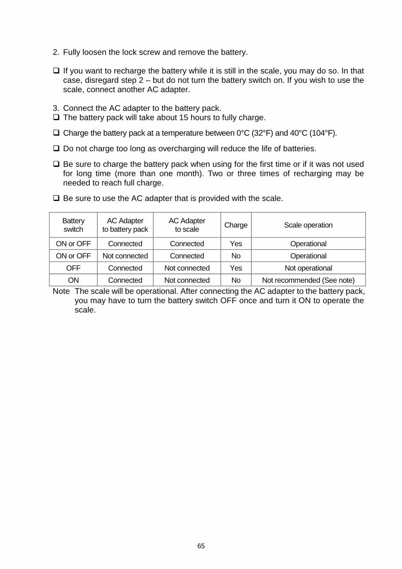
65
2. Fully loosen the lock screw and remove the battery.
If you want to recharge the battery while it is still in the scale, you may do so. In thatcase, disregard step 2 – but do not turn the battery switch on. If you wish to use thescale, connect another AC adapter.
3. Connect the AC adapter to the battery pack. The battery pack will take about 15 hours to fully charge.
Charge the battery pack at a temperature between 0°C (32°F) and 40°C (104°F).
Do not charge too long as overcharging will reduce the life of batteries.
Be sure to charge the battery pack when using for the first time or if it was not usedfor long time (more than one month). Two or three times of recharging may beneeded to reach full charge.
Be sure to use the AC adapter that is provided with the scale.
Batteryswitch
AC Adapterto battery pack
AC Adapterto scale Charge Scale operation
ON or OFF Connected Connected Yes OperationalON or OFF Not connected Connected No Operational
OFF Connected Not connected Yes Not operationalON Connected Not connected No Not recommended (See note)
Note The scale will be operational. After connecting the AC adapter to the battery pack,you may have to turn the battery switch OFF once and turn it ON to operate thescale.
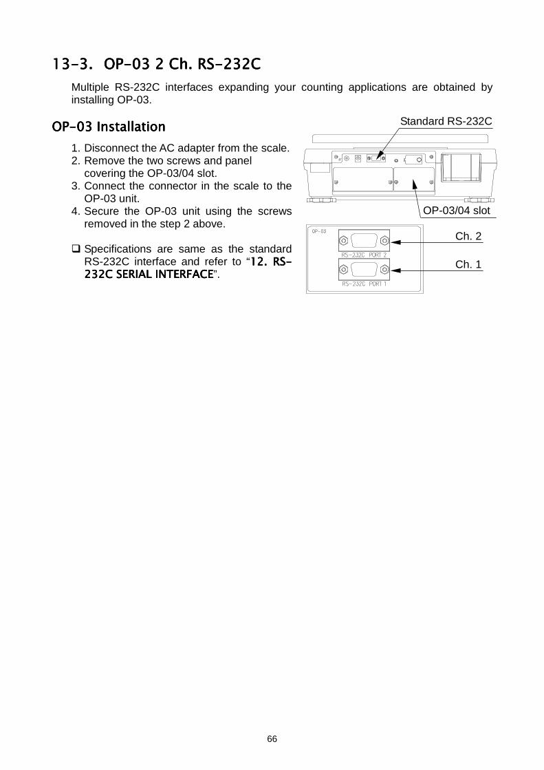
66
13-3.13-3.13-3.13-3. OP-03 2 Ch. RS-232COP-03 2 Ch. RS-232COP-03 2 Ch. RS-232COP-03 2 Ch. RS-232CMultiple RS-232C interfaces expanding your counting applications are obtained byinstalling OP-03.
OP-03 InstallationOP-03 InstallationOP-03 InstallationOP-03 Installation1. Disconnect the AC adapter from the scale.2. Remove the two screws and panel
covering the OP-03/04 slot.3. Connect the connector in the scale to the
OP-03 unit.4. Secure the OP-03 unit using the screws
removed in the step 2 above.
Specifications are same as the standardRS-232C interface and refer to “12121212. RS-. RS-. RS-. RS-232C SERIAL INTERFACE232C SERIAL INTERFACE232C SERIAL INTERFACE232C SERIAL INTERFACE”.
Standard RS-232C
OP-03/04 slot
Ch. 2
Ch. 1
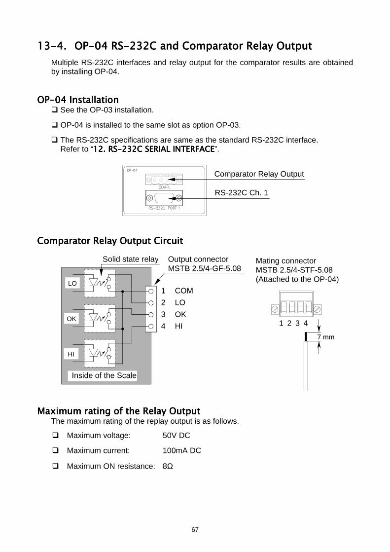
67
13-4.13-4.13-4.13-4. OP-04 RS-232C and Comparator Relay OutputOP-04 RS-232C and Comparator Relay OutputOP-04 RS-232C and Comparator Relay OutputOP-04 RS-232C and Comparator Relay OutputMultiple RS-232C interfaces and relay output for the comparator results are obtainedby installing OP-04.
OP-04 InstallationOP-04 InstallationOP-04 InstallationOP-04 Installation See the OP-03 installation.
OP-04 is installed to the same slot as option OP-03.
The RS-232C specifications are same as the standard RS-232C interface.Refer to “12121212. RS-232C SERIAL INTERFACE. RS-232C SERIAL INTERFACE. RS-232C SERIAL INTERFACE. RS-232C SERIAL INTERFACE”.
Comparator Relay Output CircuitComparator Relay Output CircuitComparator Relay Output CircuitComparator Relay Output Circuit
Maximum rating of the Relay OutputMaximum rating of the Relay OutputMaximum rating of the Relay OutputMaximum rating of the Relay OutputThe maximum rating of the replay output is as follows.
Maximum voltage: 50V DC
Maximum current: 100mA DC
Maximum ON resistance: 8Ω
Comparator Relay Output
RS-232C Ch. 1
Inside of the Scale
Output connectorMSTB 2.5/4-GF-5.08
Solid state relay Mating connectorMSTB 2.5/4-STF-5.08(Attached to the OP-04)
1 2 3 4
7 mm
1 COM2 LO3 OK4 HI
LO
OK
HI
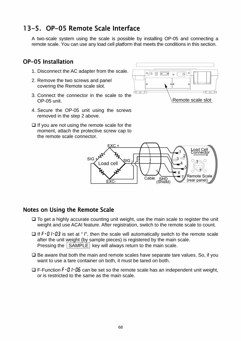
68
13-5.13-5.13-5.13-5. OP-05 Remote Scale InterfaceOP-05 Remote Scale InterfaceOP-05 Remote Scale InterfaceOP-05 Remote Scale InterfaceA two-scale system using the scale is possible by installing OP-05 and connecting aremote scale. You can use any load cell platform that meets the conditions in this section.
OP-05 InstallationOP-05 InstallationOP-05 InstallationOP-05 Installation1. Disconnect the AC adapter from the scale.
2. Remove the two screws and panelcovering the Remote scale slot.
3. Connect the connector in the scale to theOP-05 unit.
4. Secure the OP-05 unit using the screwsremoved in the step 2 above.
If you are not using the remote scale for themoment, attach the protective screw cap tothe remote scale connector.
Notes on Using Notes on Using Notes on Using Notes on Using thethethethe Remote Scale Remote Scale Remote Scale Remote Scale To get a highly accurate counting unit weight, use the main scale to register the unit
weight and use ACAI feature. After registration, switch to the remote scale to count.
If f-01-03f-01-03f-01-03f-01-03 is set at “1111”, then the scale will automatically switch to the remote scaleafter the unit weight (by sample pieces) is registered by the main scale.Pressing the SAMPLE key will always return to the main scale.
Be aware that both the main and remote scales have separate tare values. So, if youwant to use a tare container on both, it must be tared on both.
F-Function f-01-06f-01-06f-01-06f-01-06 can be set so the remote scale has an independent unit weight,or is restricted to the same as the main scale.
Remote scale slot
Load cell

69
Specifications for Remote ScaleSpecifications for Remote ScaleSpecifications for Remote ScaleSpecifications for Remote ScaleThe scale has the ability of driving up to 4 load cells (350Ω) in a remote scale (platform).Set for the capacity range 0.5kg to 5,000kg (1 lb to 10,000 lb).
The scale has the ability of driving up to 4 load cells (350Ω) in a remote scale(platform).
Capacity range for the remote scale is 0.5kg to 5,000kg (1 lb to 10,000 lb).
Minimum output at zero point is 1mV.
Maximum output at full load is 14mV.
Excitation Voltage of the scale is 5V.
Cable length should be kept under 5m (16.5 ft.) for higher accuracy.
Pin connection (JM:NJC-207-PF):
The Load Cell and Input SensitivityThe Load Cell and Input SensitivityThe Load Cell and Input SensitivityThe Load Cell and Input SensitivityThe relationship between load cell and input sensitivity (X) for the scale is follows:
Example Load Cell Capacity 100kg “A”Rated Output 3mV/V “B”Min., Division of Display 0.01kg “D”
When a single Load Cell is used,the following formula should apply:
System design will be satisfactory if “X” isgreater than 0.5µV. In the example above
Capacity and ResolutionCapacity and ResolutionCapacity and ResolutionCapacity and Resolution The resolution of the remote scale is automatically determined during the calibration
procedure. The following is to enable you to calculate the resolution for a given capacity.1. Decide the capacity value and assign it to “Ws”. Maximum 5 digits.
2. Get the maximum count “Ns” for the capacity. Ignore the decimal point and add “0”to Ws until it is 5 digits.
3. Calculate: d’=Ns/10,000.
4. Decide the minimum division “d”.d’=1 d=12≥d’>1 d=25≥d’>2 d=5d’>5 d=10 This should be changed to d=1, dividing Ns by 10.
5. Now “Ns x d” and the resolution 1/No = d/Ns can be determined.
5,000 x B x DA“X”= µV
“X” = 1.5µV.
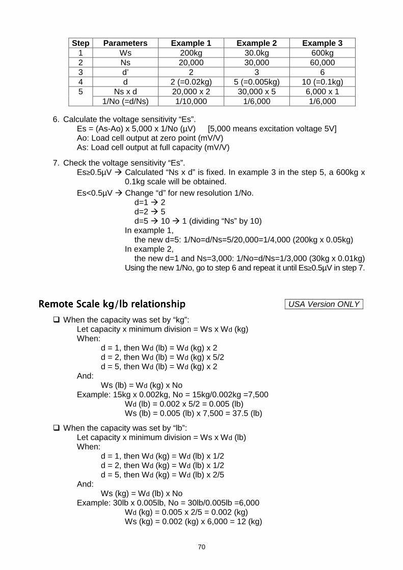
70
Step Parameters Example 1 Example 2 Example 31 Ws 200kg 30.0kg 600kg2 Ns 20,000 30,000 60,0003 d’ 2 3 64 d 2 (=0.02kg) 5 (=0.005kg) 10 (=0.1kg)
Ns x d 20,000 x 2 30,000 x 5 6,000 x 151/No (=d/Ns) 1/10,000 1/6,000 1/6,000
6. Calculate the voltage sensitivity “Es”.Es = (As-Ao) x 5,000 x 1/No (µV) [5,000 means excitation voltage 5V]Ao: Load cell output at zero point (mV/V)As: Load cell output at full capacity (mV/V)
7. Check the voltage sensitivity “Es”.Es≥0.5µV Calculated “Ns x d” is fixed. In example 3 in the step 5, a 600kg x
0.1kg scale will be obtained.Es<0.5µV Change “d” for new resolution 1/No.
d=1 2d=2 5d=5 10 1 (dividing “Ns” by 10)
In example 1,the new d=5: 1/No=d/Ns=5/20,000=1/4,000 (200kg x 0.05kg)
In example 2,the new d=1 and Ns=3,000: 1/No=d/Ns=1/3,000 (30kg x 0.01kg)
Using the new 1/No, go to step 6 and repeat it until Es≥0.5µV in step 7.
Remote Scale kg/lb relationshipRemote Scale kg/lb relationshipRemote Scale kg/lb relationshipRemote Scale kg/lb relationship When the capacity was set by “kg”:
Let capacity x minimum division = Ws x Wd (kg)When:
d = 1, then Wd (lb) = Wd (kg) x 2d = 2, then Wd (lb) = Wd (kg) x 5/2d = 5, then Wd (lb) = Wd (kg) x 2
And:Ws (lb) = Wd (kg) x No
Example: 15kg x 0.002kg, No = 15kg/0.002kg =7,500Wd (lb) = 0.002 x 5/2 = 0.005 (lb)Ws (lb) = 0.005 (lb) x 7,500 = 37.5 (lb)
When the capacity was set by “lb”:Let capacity x minimum division = Ws x Wd (lb)When:
d = 1, then Wd (kg) = Wd (lb) x 1/2d = 2, then Wd (kg) = Wd (lb) x 1/2d = 5, then Wd (kg) = Wd (lb) x 2/5
And:Ws (kg) = Wd (lb) x No
Example: 30lb x 0.005lb, No = 30lb/0.005lb =6,000Wd (kg) = 0.005 x 2/5 = 0.002 (kg)Ws (kg) = 0.002 (kg) x 6,000 = 12 (kg)
USA Version ONLY
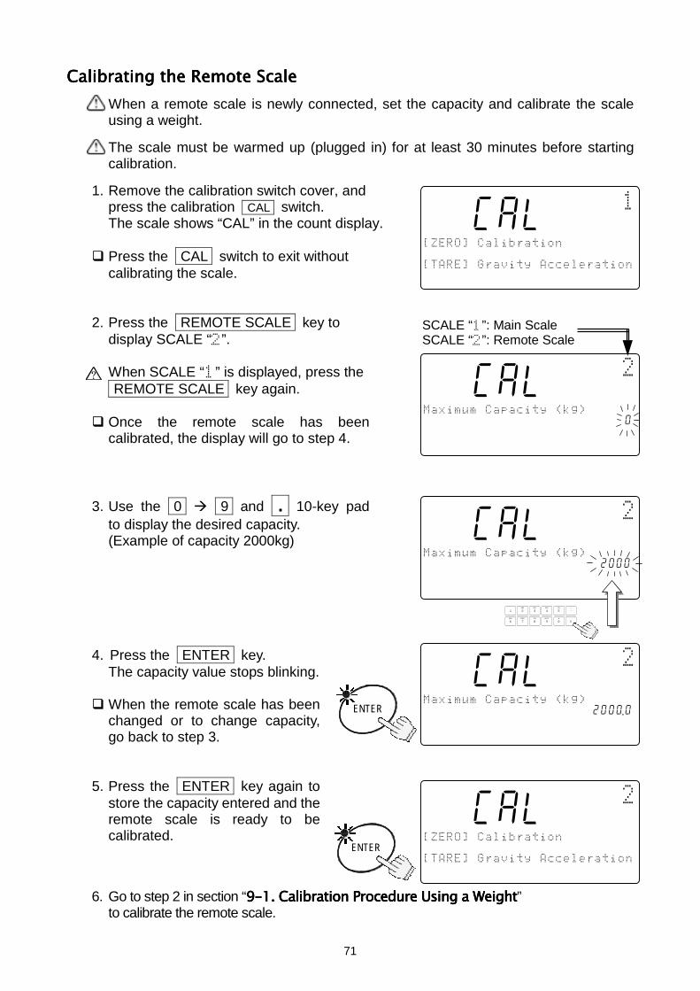
71
Calibrating the Remote ScaleCalibrating the Remote ScaleCalibrating the Remote ScaleCalibrating the Remote ScaleWhen a remote scale is newly connected, set the capacity and calibrate the scaleusing a weight.
The scale must be warmed up (plugged in) for at least 30 minutes before startingcalibration.
1. Remove the calibration switch cover, andpress the calibration CAL switch.The scale shows “CAL” in the count display.
Press the CAL switch to exit withoutcalibrating the scale.
2. Press the REMOTE SCALE key todisplay SCALE “”.
When SCALE “” is displayed, press the REMOTE SCALE key again.
Once the remote scale has beencalibrated, the display will go to step 4.
3. Use the 0 9 and .... 10-key padto display the desired capacity.(Example of capacity 2000kg)
4. Press the ENTER key.The capacity value stops blinking.
When the remote scale has beenchanged or to change capacity,go back to step 3.
5. Press the ENTER key again tostore the capacity entered and theremote scale is ready to becalibrated.
6. Go to step 2 in section “9-19-19-19-1. Calibration Procedure Using a Weight. Calibration Procedure Using a Weight. Calibration Procedure Using a Weight. Calibration Procedure Using a Weight”to calibrate the remote scale.
88Cal10
!"
1234567890123#$ "%&'$((
1234567890123
88Cal10
)*+,+-('
Cal4567890123aaaaaaaaa10 .000#$ "%&'$((
1234567890123
SCALE “”: Main ScaleSCALE “”: Remote Scale
ENTER
88Cal10
)*+,+-('
Cal4567890123aaaaaaaaa12000#$ "%&'$((
1234567890123
TUV
DEFABC
MNO
6
1
7 8PQRS
2 3JKLGHI
09WXYZ
4
#
5
C
.
88Cal10
)*+,+-('
Cal4567890123aaaaaaaaa2000 .0#$ "%&'$((
1234567890123
ENTER
88Cal10
!"
1234567890123#$ "%&'$((
1234567890123
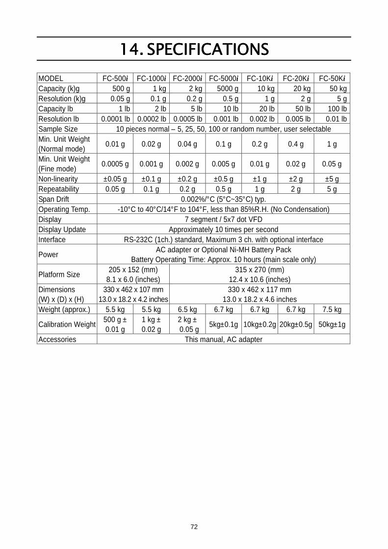
72
14.14.14.14. SPECIFICATIONSSPECIFICATIONSSPECIFICATIONSSPECIFICATIONSMODEL FC-500i FC-1000i FC-2000i FC-5000i FC-10Ki FC-20Ki FC-50KiCapacity (k)g 500 g 1 kg 2 kg 5000 g 10 kg 20 kg 50 kgResolution (k)g 0.05 g 0.1 g 0.2 g 0.5 g 1 g 2 g 5 gCapacity lb 1 lb 2 lb 5 lb 10 lb 20 lb 50 lb 100 lbResolution lb 0.0001 lb 0.0002 lb 0.0005 lb 0.001 lb 0.002 lb 0.005 lb 0.01 lbSample Size 10 pieces normal – 5, 25, 50, 100 or random number, user selectableMin. Unit Weight(Normal mode) 0.01 g 0.02 g 0.04 g 0.1 g 0.2 g 0.4 g 1 g
Min. Unit Weight(Fine mode) 0.0005 g 0.001 g 0.002 g 0.005 g 0.01 g 0.02 g 0.05 g
Non-linearity ±0.05 g ±0.1 g ±0.2 g ±0.5 g ±1 g ±2 g ±5 gRepeatability 0.05 g 0.1 g 0.2 g 0.5 g 1 g 2 g 5 gSpan Drift 0.002%/°C (5°C~35°C) typ.Operating Temp. -10°C to 40°C/14°F to 104°F, less than 85%R.H. (No Condensation)Display 7 segment / 5x7 dot VFDDisplay Update Approximately 10 times per secondInterface RS-232C (1ch.) standard, Maximum 3 ch. with optional interface
Power AC adapter or Optional Ni-MH Battery PackBattery Operating Time: Approx. 10 hours (main scale only)
Platform Size 205 x 152 (mm)8.1 x 6.0 (inches)
315 x 270 (mm)12.4 x 10.6 (inches)
Dimensions(W) x (D) x (H)
330 x 462 x 107 mm13.0 x 18.2 x 4.2 inches
330 x 462 x 117 mm13.0 x 18.2 x 4.6 inches
Weight (approx.) 5.5 kg 5.5 kg 6.5 kg 6.7 kg 6.7 kg 6.7 kg 7.5 kg
Calibration Weight 500 g ±0.01 g
1 kg ±0.02 g
2 kg ± 0.05 g 5kg±0.1g 10kg±0.2g 20kg±0.5g 50kg±1g
Accessories This manual, AC adapter
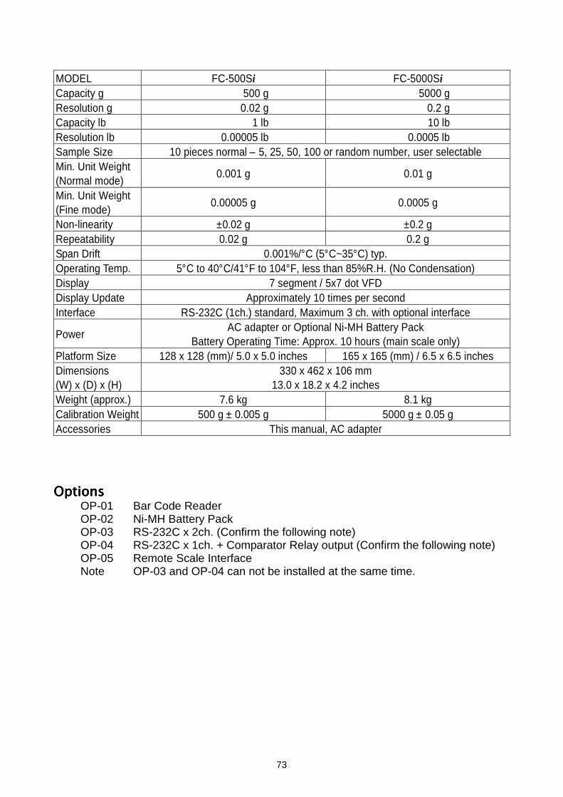
73
MODEL FC-500Si FC-5000SiCapacity g 500 g 5000 gResolution g 0.02 g 0.2 gCapacity lb 1 lb 10 lbResolution lb 0.00005 lb 0.0005 lbSample Size 10 pieces normal – 5, 25, 50, 100 or random number, user selectableMin. Unit Weight(Normal mode) 0.001 g 0.01 g
Min. Unit Weight(Fine mode) 0.00005 g 0.0005 g
Non-linearity ±0.02 g ±0.2 gRepeatability 0.02 g 0.2 gSpan Drift 0.001%/°C (5°C~35°C) typ.Operating Temp. 5°C to 40°C/41°F to 104°F, less than 85%R.H. (No Condensation)Display 7 segment / 5x7 dot VFDDisplay Update Approximately 10 times per secondInterface RS-232C (1ch.) standard, Maximum 3 ch. with optional interface
Power AC adapter or Optional Ni-MH Battery PackBattery Operating Time: Approx. 10 hours (main scale only)
Platform Size 128 x 128 (mm)/ 5.0 x 5.0 inches 165 x 165 (mm) / 6.5 x 6.5 inchesDimensions(W) x (D) x (H)
330 x 462 x 106 mm13.0 x 18.2 x 4.2 inches
Weight (approx.) 7.6 kg 8.1 kgCalibration Weight 500 g ± 0.005 g 5000 g ± 0.05 gAccessories This manual, AC adapter
OptionsOptionsOptionsOptionsOP-01 Bar Code ReaderOP-02 Ni-MH Battery PackOP-03 RS-232C x 2ch. (Confirm the following note)OP-04 RS-232C x 1ch. + Comparator Relay output (Confirm the following note)OP-05 Remote Scale InterfaceNote OP-03 and OP-04 can not be installed at the same time.
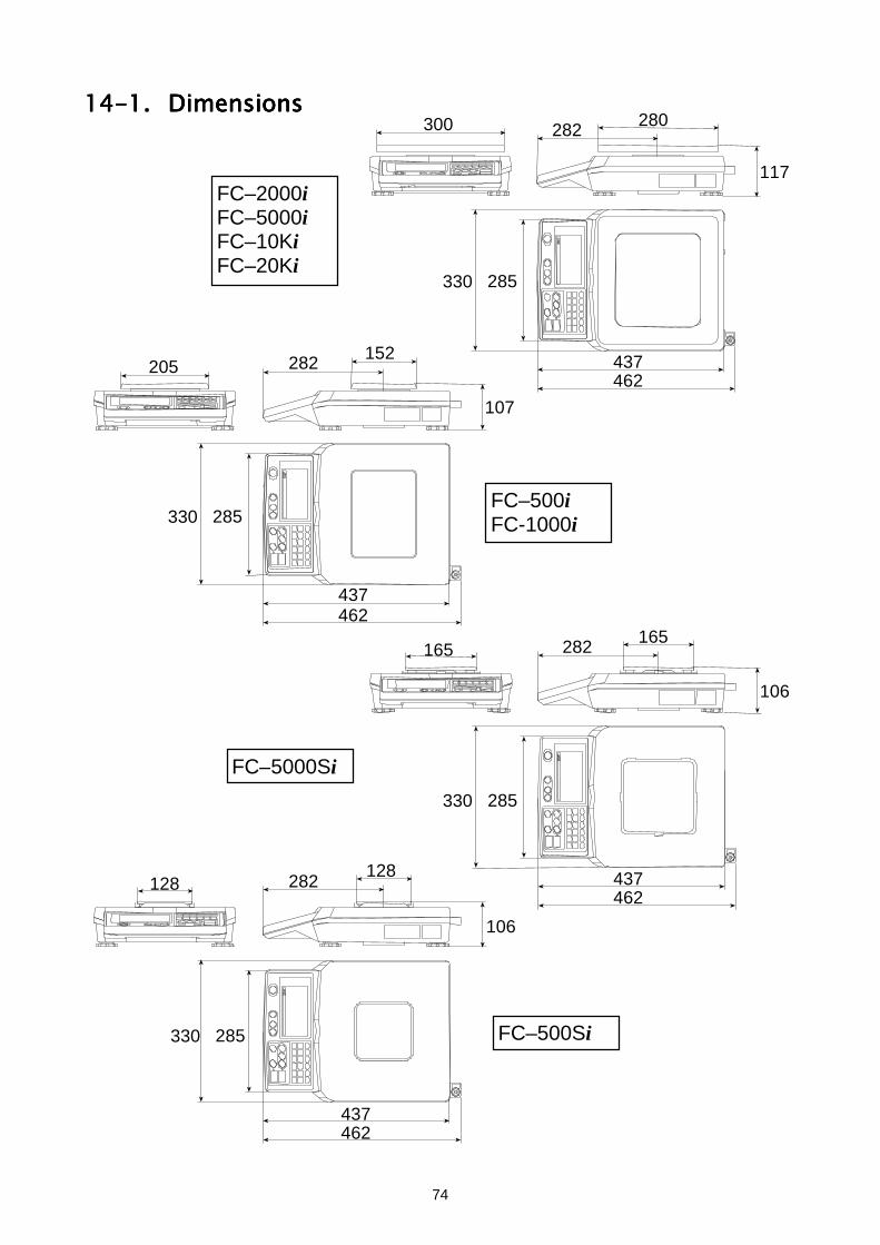
74
14-1.14-1.14-1.14-1. DimensionsDimensionsDimensionsDimensions300 280282
117
330 285
462437152
205 282
107
330 285
462437
FC–2000iFC–5000iFC–10KiFC–20Ki
FC–500iFC-1000i
FC–5000Si
FC–500Si
165165 282
106
330 285
462437128
128 282
106
330 285
462437
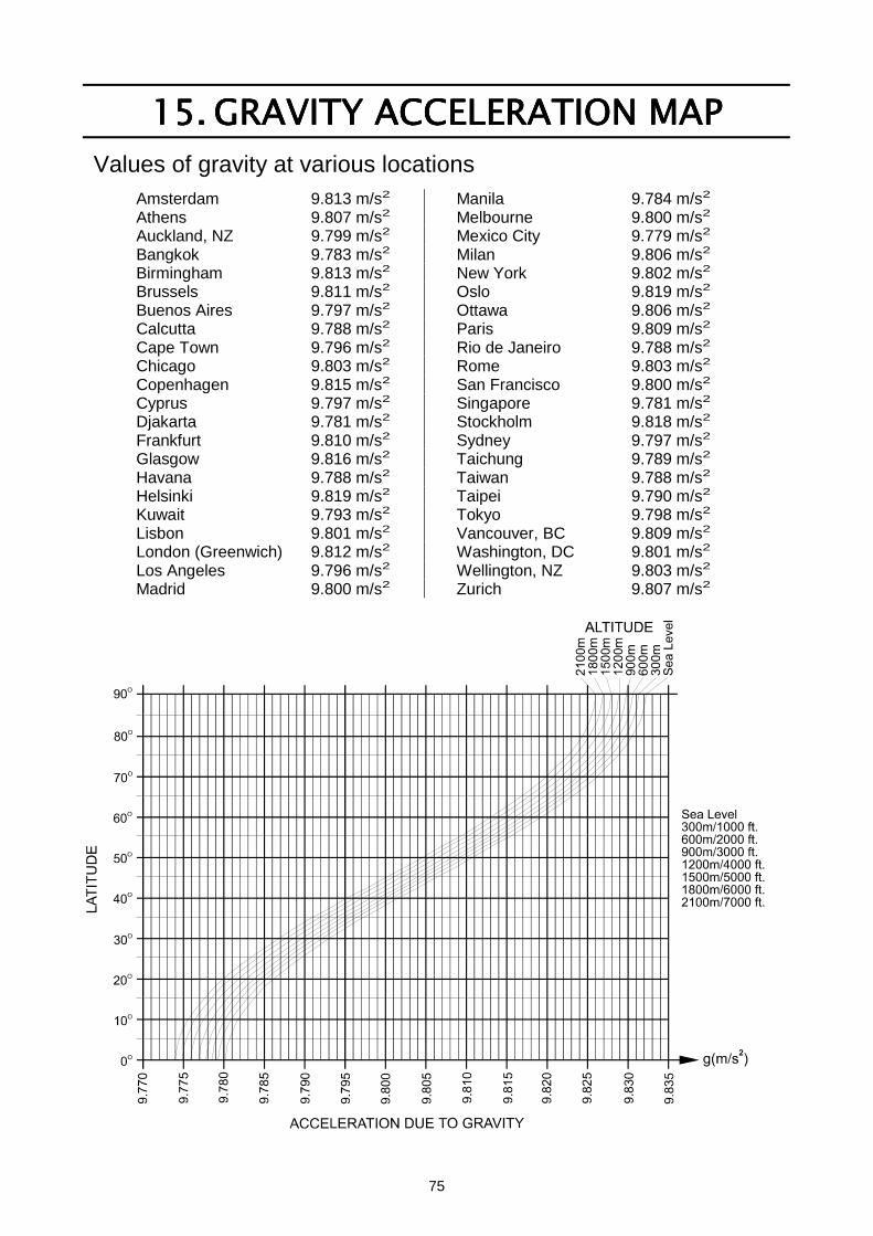
75
15.15.15.15. GRAVITY ACCELERATION MAPGRAVITY ACCELERATION MAPGRAVITY ACCELERATION MAPGRAVITY ACCELERATION MAPValues of gravity at various locations
Amsterdam 9.813 m/s2 Manila 9.784 m/s2
Athens 9.807 m/s2 Melbourne 9.800 m/s2
Auckland, NZ 9.799 m/s2 Mexico City 9.779 m/s2
Bangkok 9.783 m/s2 Milan 9.806 m/s2
Birmingham 9.813 m/s2 New York 9.802 m/s2
Brussels 9.811 m/s2 Oslo 9.819 m/s2
Buenos Aires 9.797 m/s2 Ottawa 9.806 m/s2
Calcutta 9.788 m/s2 Paris 9.809 m/s2
Cape Town 9.796 m/s2 Rio de Janeiro 9.788 m/s2
Chicago 9.803 m/s2 Rome 9.803 m/s2
Copenhagen 9.815 m/s2 San Francisco 9.800 m/s2
Cyprus 9.797 m/s2 Singapore 9.781 m/s2
Djakarta 9.781 m/s2 Stockholm 9.818 m/s2
Frankfurt 9.810 m/s2 Sydney 9.797 m/s2
Glasgow 9.816 m/s2 Taichung 9.789 m/s2
Havana 9.788 m/s2 Taiwan 9.788 m/s2
Helsinki 9.819 m/s2 Taipei 9.790 m/s2
Kuwait 9.793 m/s2 Tokyo 9.798 m/s2
Lisbon 9.801 m/s2 Vancouver, BC 9.809 m/s2
London (Greenwich) 9.812 m/s2 Washington, DC 9.801 m/s2
Los Angeles 9.796 m/s2 Wellington, NZ 9.803 m/s2
Madrid 9.800 m/s2 Zurich 9.807 m/s2

76
World map
77
16.16.16.16. INDEXINDEXINDEXINDEX------- ....................... 10, 11, 13, 14, 15 key ............................... 9, 27, 29, 42~ , Space code ......................... 52, 59, 60
,Standby indicator ............................ 7
AC adapter...................................... 4, 5, 6AC adapter jack...................................... 5ACAI......................................... 38, 44, 45ACAI indicator ........................................ 9Accessories.................................... 72, 73AD-8121................................... 41, 48, 49Add....................................................... 36Add Sample.................... 13, 14, 15, 16Alphanumeric character table .............. 24Bar code
Bar code reader .......................... 55, 61Check digit .................................. 57, 62Codabar (NW-7).......................... 57, 62Code 39 ...................................... 57, 62EAN/JAN-13................................ 57, 62EAN/JAN-8.................................. 57, 62Identification code ............................. 56Interleaved 2 of 5 ........................ 57, 62PF command..................................... 58UFC (Universal Flex Coms) .............. 58UPC-A......................................... 57, 62
Battery.................................................. 64Baud rate ................................. 41, 46, 48Best conditions....................................... 5C key...................................................... 9Cal ....................................................... 31Cal 0 ................................................... 32Cal f ................................................... 32Calibration ............................. 31, 71Calibration End ........................... 32Calibration switch ............................. 5, 31Calibration weight..................... 32, 72, 73Capacity ......................................... 72, 73Capital letter................................... 23, 24Comparator function............................. 28
Comparator limit................................ 25Comparator result ............................. 40Lower limit ............................. 28, 29, 40Upper limit ............................. 28, 29, 40
Count data ........................................... 26
Counting............................................... 12Data format ........................ 41, 46, 48, 52Data length........................................... 41Date and time....................................... 47Dimensions .................................... 72, 73Display off .............................................. 5Earth terminal......................................... 5ENTER key ............................................ 9err 1 ................................................... 10Error code ............................................ 51f-00 ..................................................... 34F-Function............................................ 34Gravity acceleration ................. 32, 33, 75HI .................................................. 28, 40Humidity ................................................. 6id ..................................................... 8, 18id------- ........................................... 22ID key............................................... 9, 25ID number ................................................
.........8, 9, 12, 18, 21, 22, 23, 25, 47, 61id-all ................................................. 22Interface ............................. 46, 66, 67, 68Item code ................................. 21, 23, 25KEYBOARD TARE key.......................... 9LO .................................................. 28, 40lo bat ................................................. 64lo ut ............................................. 16, 17Load cell................................... 68, 69, 71Lowercase letter............................. 23, 24M- key ........................................ 9, 27, 42M+ (A/a) key................................... 23, 24M+ indicator ..................................... 9, 26M+ key ............................................. 9, 26Memory function ...................... 26, 37, 38Minimum unit weight ............................ 38Mode
Auto-print mode A ............................. 47Auto-print mode B ............................. 47Calibration......................................... 31Command mode ............................... 50Comparator mode ............................. 39Data output mode ....................... 40, 47Key mode.......................................... 47Normal operation .............................. 36
78
Operating mode ............................ 7, 36Simple operation ............................... 36Simple operation mode ....................... 7Standby mode..................................... 7Stream mode..................................... 47
Net weight ............................................ 19no id ................................................... 18Numerical keys........................... 9, 23, 24OK ................................................. 28, 40OP-01................................................... 61OP-02................................................... 64OP-03................................................... 66OP-04................................................... 67OP-05................................................... 68Operating mode ................................... 36Operating temperature ............... 6, 72, 73Parity.............................................. 41, 46pcs ...................13, 14, 15, 16, 44, 45, 47Power............................................. 72, 73PRINT key........................................ 9, 24Printer ............................................ 48, 49Remote scale ......5, 36, 37, 44, 68, 69, 70REMOTE SCALE key ............................ 9RESET key ...................................... 9, 12Resolution ...................................... 72, 73RS-232C .................. 5, 46, 55, 61, 66, 67SAMPLE key............ 9, 13, 14, 15, 16, 17Sample size ......13, 14, 15, 16, 17, 72, 73SAMPLE TOO LIGHT indicator.............. 9Second................................................. 30Self-check .............................................. 5Signal input .......................................... 42Slot
OP-02............................................ 5, 64OP-03/04....................................... 5, 66Remote scale..................................... 68
Span calibration ................................... 32Spirit level .............................................. 5
Stable detection speed......................... 39STABLE indicator................................... 9Standby indicator ............................. 7, 10STANDBY/OPERATE key ....... 5, 7, 9, 64Start bit................................................. 46Stop bit................................................. 46STORE UNIT WEIGHT key .....................
.....................................9, 21, 22, 23, 24TARE ENTERED indicator......... 9, 11, 19TARE key................................... 9, 11, 19Tare operation...................................... 19Tare weight .......................................... 25Terminator............................................ 46Time and date ................................ 30, 43Total count ..................................... 25, 27TOTAL indicator............................... 9, 27TOTAL key........................... 9, 24, 26, 27Total weight.......................................... 13Unit..................................................... 7, 8
kg .................................................. 7, 36Kilogram........................................ 7, 36lb ................................................... 7, 36Pounds.......................................... 7, 36Weighting unit ............................... 7, 36
Unit weight ...............................................8, 12, 13, 14, 15, 16, 17, 18, 21, 22, 25,37, 44, 45, 47, 72, 73Minimum unit weight ......................... 38UW(g) .........8, 9, 13, 14, 18, 21, 44, 45UW(lb) .............................................. 7
Warm up ...................................... 5, 6, 31Weighing pan ......................................... 5Weight............................................ 72, 73Zero calibration .................................... 32ZERO indicator ................................ 9, 10ZERO key ........................................ 9, 10Zero tracking .................................. 10, 39

79
MEMO

80
MEMO