counterweight trunnion replacement - louisiana ... bridges... · louisiana transportation...
TRANSCRIPT
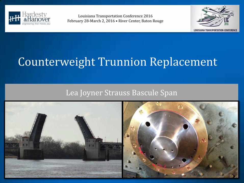
Louisiana Transportation Conference 2016 February 28-March 2, 2016 • River Center, Baton Rouge
Counterweight Trunnion Replacement
Lea Joyner Strauss Bascule Span
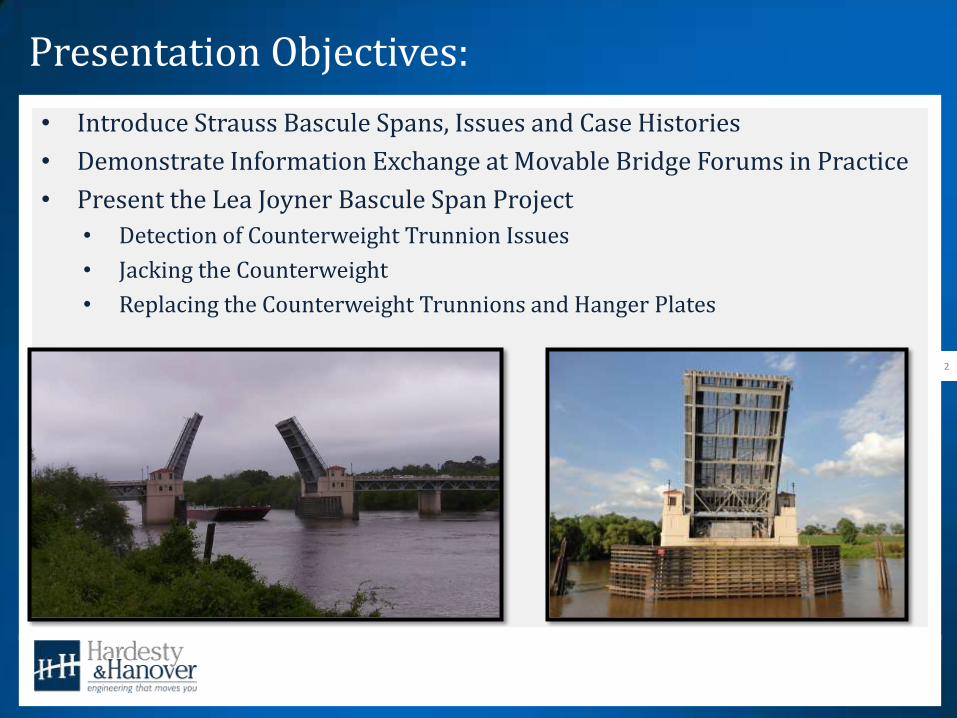
Presentation Objectives:
• Introduce Strauss Bascule Spans, Issues and Case Histories
• Demonstrate Information Exchange at Movable Bridge Forums in Practice
• Present the Lea Joyner Bascule Span Project
• Detection of Counterweight Trunnion Issues
• Jacking the Counterweight
• Replacing the Counterweight Trunnions and Hanger Plates
2
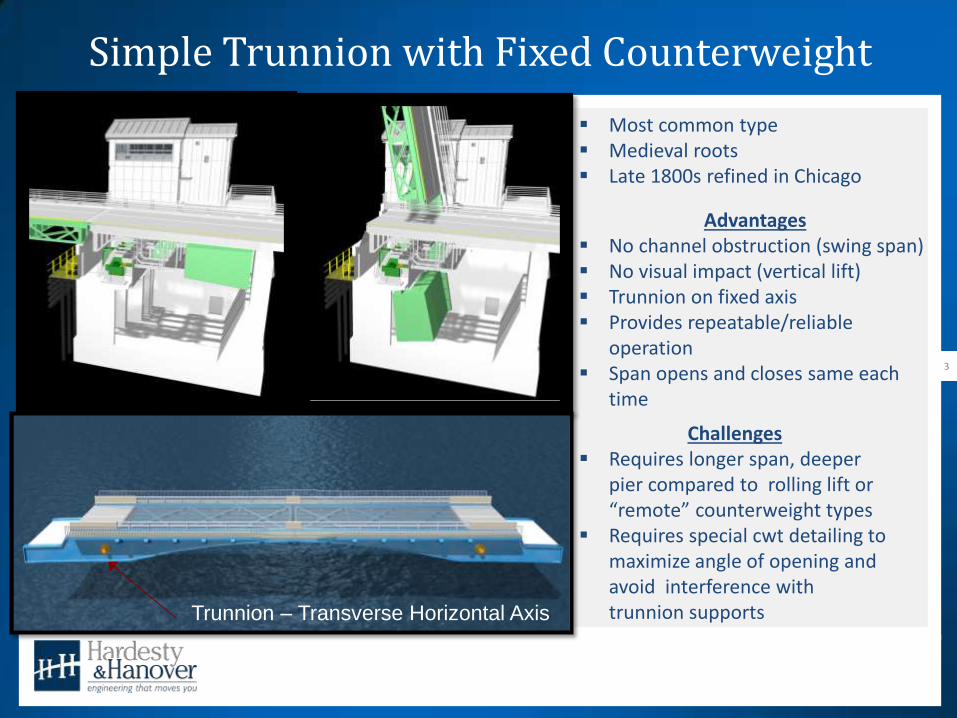
Simple Trunnion with Fixed Counterweight
3
Advantages No channel obstruction (swing span) No visual impact (vertical lift) Trunnion on fixed axis Provides repeatable/reliable
operation Span opens and closes same each
time
Challenges Requires longer span, deeper
pier compared to rolling lift or “remote” counterweight types
Requires special cwt detailing to maximize angle of opening and avoid interference with trunnion supports Trunnion – Transverse Horizontal Axis
Most common type Medieval roots Late 1800s refined in Chicago

Simple Trunnion with Fixed Counterweight
4
1800s- increasing need for railroad and ship traffic to co-exist Prompted developments in movable bridge technology

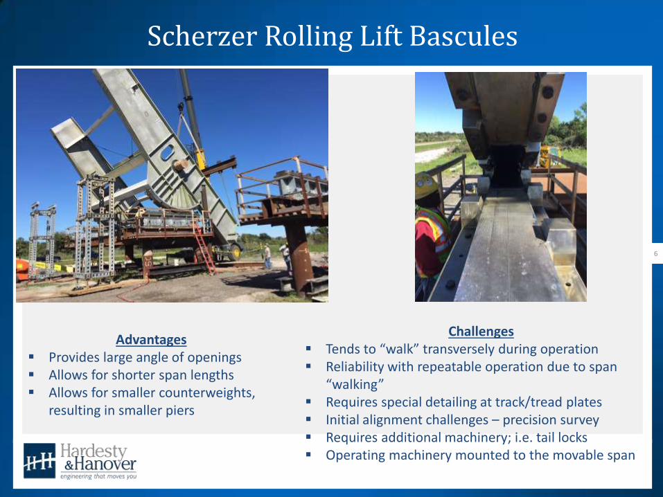
Scherzer Rolling Lift Bascules
5
Metropolitan West Side Elevated Company Needed 4 tracks across Chicago River (early 1890s) – between Jackson and Van Buren streets William Scherzer consulted Swing span too obstructive Trunnion bascule encroached on navigation width Scherzer Rolling Lift Patented in 1893 (Scherzer died at 35, 2 months after filing patent) Movable Bridge Tech Wars - Battleground: Chicago
Scherzer Rolling Lift Bascules
6
Advantages Provides large angle of openings Allows for shorter span lengths Allows for smaller counterweights,
resulting in smaller piers
Challenges Tends to “walk” transversely during operation Reliability with repeatable operation due to span
“walking” Requires special detailing at track/tread plates Initial alignment challenges – precision survey Requires additional machinery; i.e. tail locks Operating machinery mounted to the movable span

Simple Trunnion vs. Scherzer Rolling Lift Bascules
7
125’ Channel
150’ C-C Roll
180’ C-C Trunnion
Strauss Bascules
8
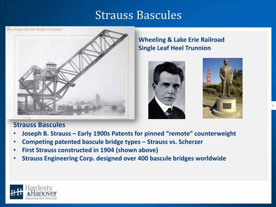
Strauss Bascules • Joseph B. Strauss – Early 1900s Patents for pinned “remote” counterweight • Competing patented bascule bridge types – Strauss vs. Scherzer • First Strauss constructed in 1904 (shown above) • Strauss Engineering Corp. designed over 400 bascule bridges worldwide
Wheeling & Lake Erie Railroad Single Leaf Heel Trunnion

Strauss Bascules
9 Under-Deck Articulated Counterweight
Heel Trunnion Vertical Overhead Counterweight
Strauss Heel Trunnion Bascule
10
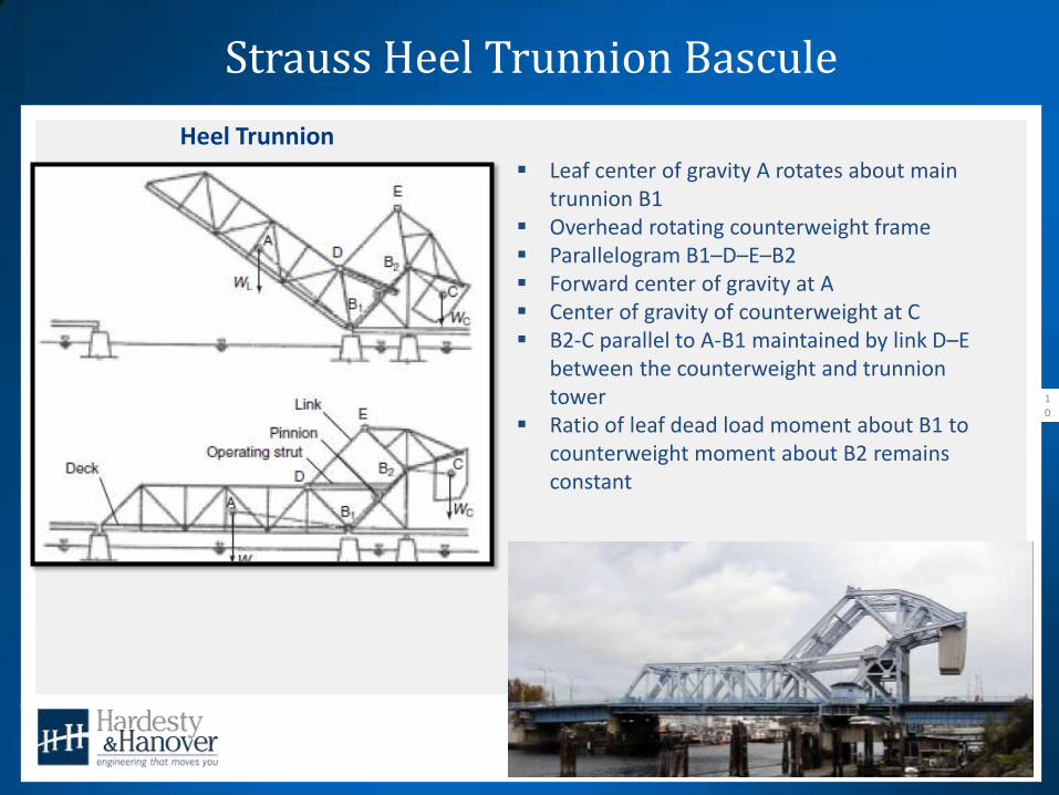
Heel Trunnion
Leaf center of gravity A rotates about main trunnion B1
Overhead rotating counterweight frame Parallelogram B1–D–E–B2 Forward center of gravity at A Center of gravity of counterweight at C B2-C parallel to A-B1 maintained by link D–E
between the counterweight and trunnion tower
Ratio of leaf dead load moment about B1 to counterweight moment about B2 remains constant

Strauss Heel Trunnion Bascule
11
Advantages Small Substructure Allows for low profiles without cwt pit Pivot/Trunnion closer to navigation
channel; providing same channel as simple trunnion with shorter leaf
Issues Stress reversals at rocking truss and
counterweight link Overstressed pins and rocking truss

Strauss Heel Trunnion Bascule
12
Main Trunnion
Operating Strut
Pinion
Link Rocking Truss Cwt Trunnion
Strauss Vertical Overhead Counterweight Bascule
13
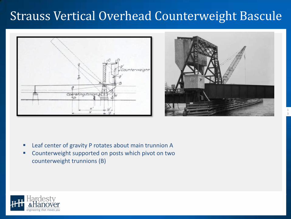
Leaf center of gravity P rotates about main trunnion A Counterweight supported on posts which pivot on two
counterweight trunnions (B)

Strauss Vertical Overhead Counterweight Bascule
14
Advantages Small Substructure Allows for low profiles
without pit
Issues Inadequate counterweight
tower on some versions 1928 Hackensack River
Bridge Failure Dynamic Effects not
considered
Saugus River Bridge Boston & Maine RR Vertical Overhead Counterweight

Strauss Under-Deck Articulated Counterweight Bascule
15
Strauss moved rear center of gravity closer to main trunnion
Leaf center of gravity A rotates about main trunnion B Line A-C intersects main trunnion axis B Counterweight hangs from two counterweight
trunnions Parallelogram B–C–E–D maintained by link D–E
between the counterweight and trunnion tower
The Strauss Bascule Bridge Company
16
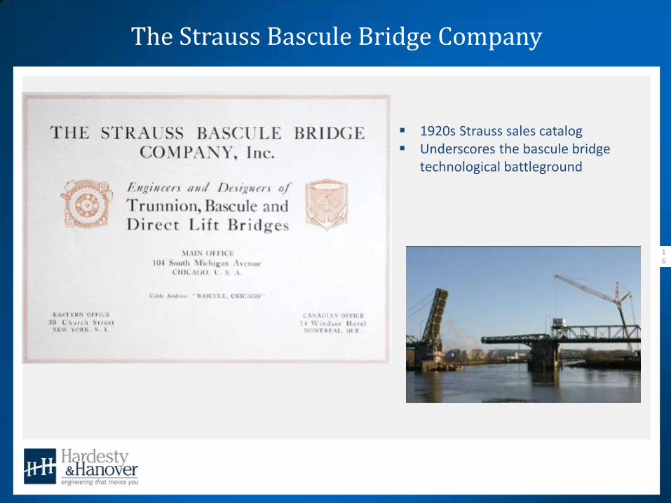
1920s Strauss sales catalog Underscores the bascule bridge
technological battleground
The Strauss Bascule Bridge Company
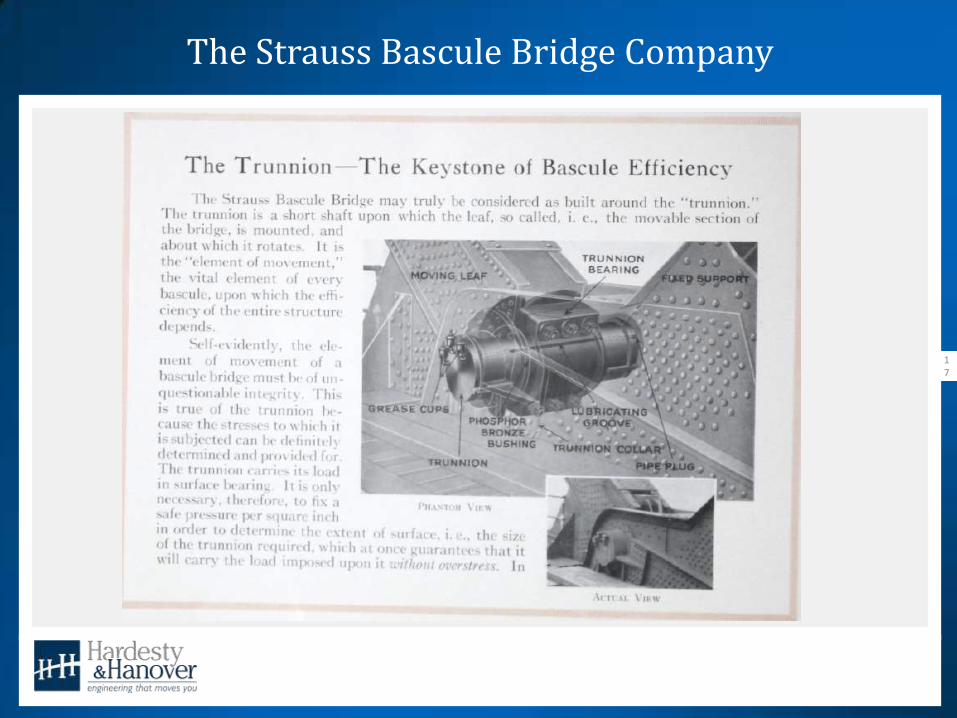
17

The Strauss Bascule Bridge Company
18
The Strauss Bascule Bridge Company
19
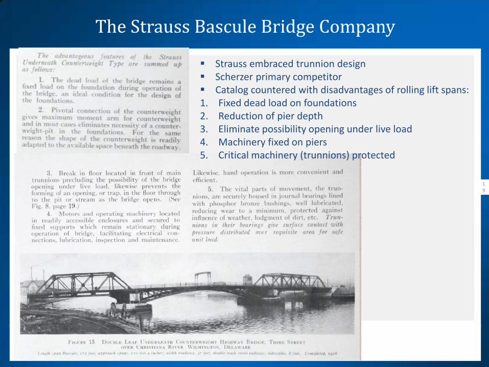
Strauss embraced trunnion design Scherzer primary competitor Catalog countered with disadvantages of rolling lift spans: 1. Fixed dead load on foundations 2. Reduction of pier depth 3. Eliminate possibility opening under live load 4. Machinery fixed on piers 5. Critical machinery (trunnions) protected

Strauss Under-Deck Articulated Counterweight Bascule
20
Issues Excessive friction in the counterweight linkage and
trunnion bearings induces repetitive bending moment in the counterweight hangers – especially at small angle of openings
By early 1930s counterweights were falling off Hangers failed in fatigue due to seized counterweight
trunnion bearings resulting in collapse of leaves

Tayco St. Bridge Collapse
21
Collapse of Tayco St. Bridge over the US Canal, Menasha, WI • Constructed in 1928 • Collapse of South Leaf in 1989 • West counterweight bearing seized at 10 degree opening • Subsequent failure of hangers and counterweight links

Strauss Bascules – History of Issues
22
Bridge Name/Location Type/Year Built Issue Industry Presentation
Passaic River Crossing, Newark, NJ Single Leaf Heel Trunnion/1915 Counterweight Trunnions 1985
Tayco St Bridge, Menasha, WI Double Leaf Underdeck Cwt/1928 Seized Counterweight Trunnion 1990
AMTRAK’s Thames River Bridge, New London,
CT Single Leaf Heel Trunnion/1919
Counterweight Trunnions Replaced in 2009
with Vertical Lift Span 1992
Dorset Ave Bridge, Atlantic City, NJ Double Leaf Underdeck Cwt/1926 Counterweight Trunnions 1996
East Washington Avenue, Bridgeport, CT Single Leaf Underdeck Cwt/1916 Replaced in-kind in 1998 2000
Tomlinson Bridge, New Haven, CT Twin Double Leaf Underdeck
Cwt/1929 Replaced with Vertical Lift Span/2002 2002
Burnside Bridge. Portland, OR Double Leaf Underdeck Cwt/1926 Counterweight Trunnions, Hanger Plates 2008
Meadowbrook Pkwy over Sloop Channel &
Loop Pkwy over Long Creek, Long Island, NY Double Leaf Underdeck Cwt/1930s
Counterweight Trunnions, Hanger Plates,
Links 2010
Gloucester Draw (MBTA), Gloucester, MA Single Leaf Underdeck Cwt/1911 Counterweight Trunnions, Hanger Plates 2012

Strauss Bascules – History of Issues
23
Burnside Bridge Bascule Span, Portland, OR 1926 Strauss Under-Deck Articulated Counterweight 4 Million LB Leaf 2007 $5.5M Cwt Trunnion and Hanger Plate Replacement
Simpson Ave. Bridge, Hoquiam, WA 1928 Strauss Under-Deck Articulated Counterweight 2007 Cwt Trunnions and Hanger Plate Replacement
Platt St Bridge, Tampa, FL 1926 Strauss Under-Deck Articulated Counterweight 2012 Cwt trunnion Replacement
Salmon Bay Bridge, Burlington Northern Santa Fe (BNSF) Railway, Ballard, WA 1914 Strauss Heel Trunnion 5.5 Million LB Leaf 2010 $3.5M Cwt trunnion Replacement

Lea Joyner Bridge Strauss Bascule Span
24
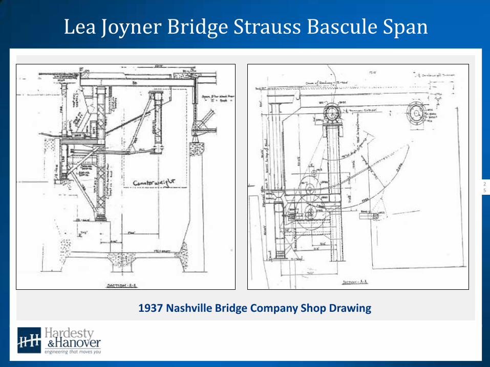
• Strauss Bascule - Under-Deck Articulated Counterweight • Constructed in 1937 – one of last designed by Strauss • 160 ft main trunnion to main trunnion – 130 ft channel • 4 Lanes with 6.5 ft sidewalks • 3M LB Leaf/1.4M LB Cwt
Lea Joyner Bridge Strauss Bascule Span
25
1937 Nashville Bridge Company Shop Drawing

Project Location
26
US 80/LA 15 from Monroe to West Monroe
Ouachita Parish, LADOTD District 05 Boeuf River – Ouachita River System
Location – Looking South over the Boeuf River
27
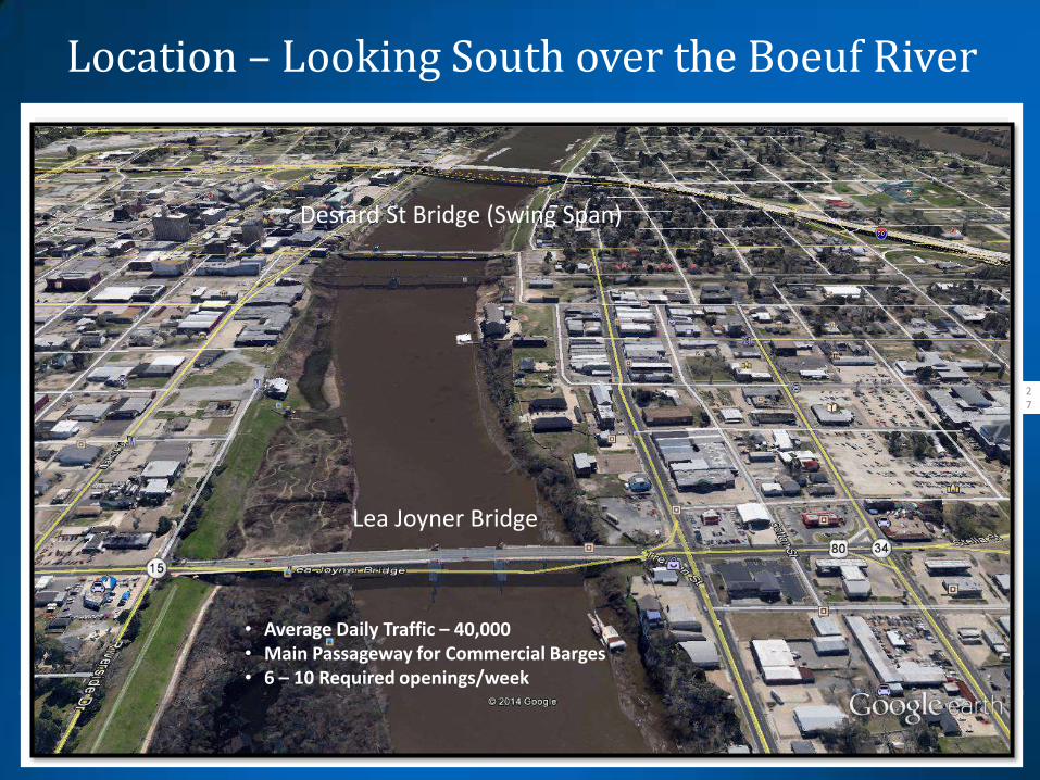
Desiard St Bridge (Swing Span)
Lea Joyner Bridge
• Average Daily Traffic – 40,000 • Main Passageway for Commercial Barges • 6 – 10 Required openings/week

Project Development
28
2010 - 2012 Project • Deck Replacement • Structural Steel Rehabilitation • Operating Machinery – New Open Gears • Rehabilitate Center Span Locks
Designer: LADOTD Bridge Design Section Contractor: PCL Civil Constructors Subcontractor: Electro Hydraulic Machinery Subcontractor: JC Machine Construction Specialty Engineer: H&H
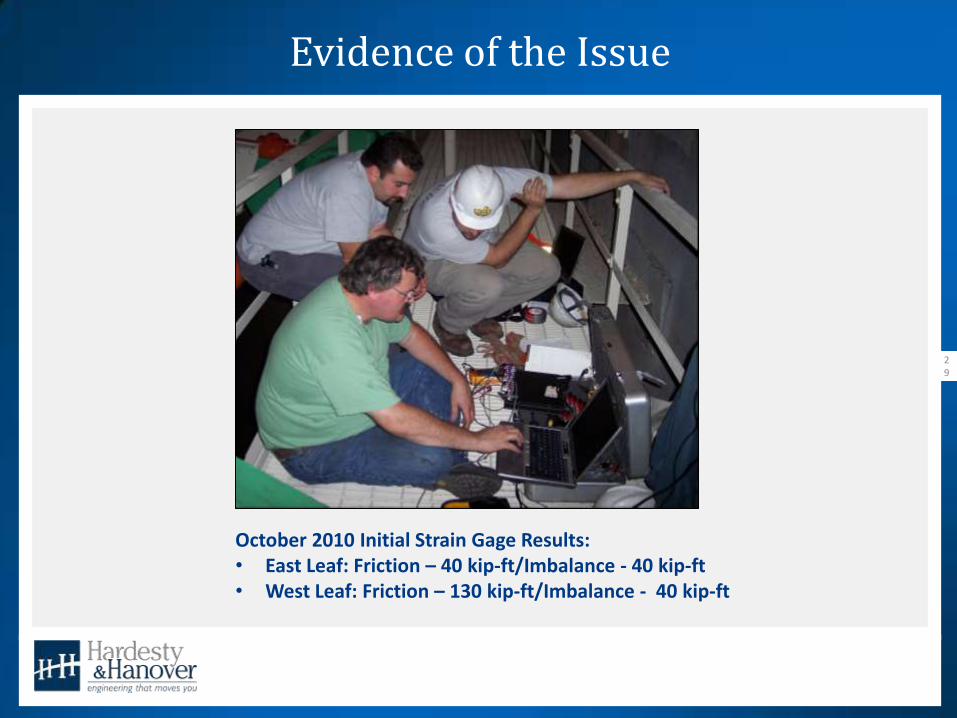
Evidence of the Issue
29
October 2010 Initial Strain Gage Results: • East Leaf: Friction – 40 kip-ft/Imbalance - 40 kip-ft • West Leaf: Friction – 130 kip-ft/Imbalance - 40 kip-ft
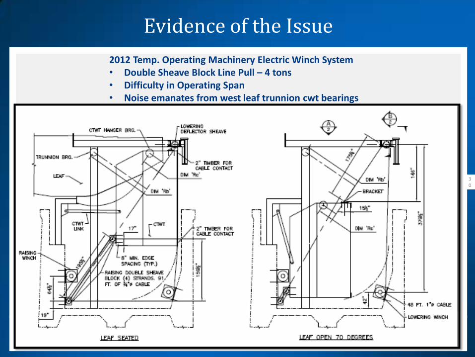
Evidence of the Issue
30
2012 Temp. Operating Machinery Electric Winch System • Double Sheave Block Line Pull – 4 tons • Difficulty in Operating Span • Noise emanates from west leaf trunnion cwt bearings
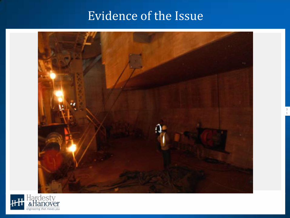
Evidence of the Issue
31
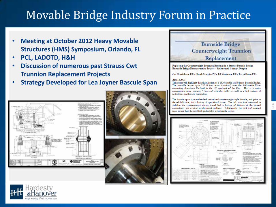
Movable Bridge Industry Forum in Practice
32
Lea Joyner Bridge
• Meeting at October 2012 Heavy Movable Structures (HMS) Symposium, Orlando, FL
• PCL, LADOTD, H&H • Discussion of numerous past Strauss Cwt
Trunnion Replacement Projects • Strategy Developed for Lea Joyner Bascule Span
Lea Joyner Bridge Counterweight Trunnion Replacement
33
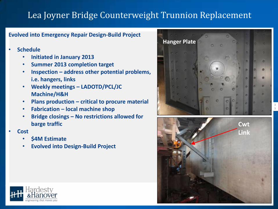
Evolved into Emergency Repair Design-Build Project • Schedule
• Initiated in January 2013 • Summer 2013 completion target • Inspection – address other potential problems,
i.e. hangers, links • Weekly meetings – LADOTD/PCL/JC
Machine/H&H • Plans production – critical to procure material • Fabrication – local machine shop • Bridge closings – No restrictions allowed for
barge traffic • Cost
• $4M Estimate • Evolved into Design-Build Project
Hanger Plate
Cwt Link

Lea Joyner Bridge Counterweight Trunnion Replacement
34
27” dia. Housing “light driving fit” with girder webs
22 ½” dia. (20 ½” I.D.) bronze bushing “driving fit” with housing
20 ½” dia. Trunnion Sleeve rotates within bushed housing
8 ½” dia. Trunnion “light driving fit” with Sleeve, fixed to hanger plates
1 ½” dia. Rods
Hanger Plate
Assembly, Typ.
Lea Joyner Bridge Counterweight Trunnion Replacement
35
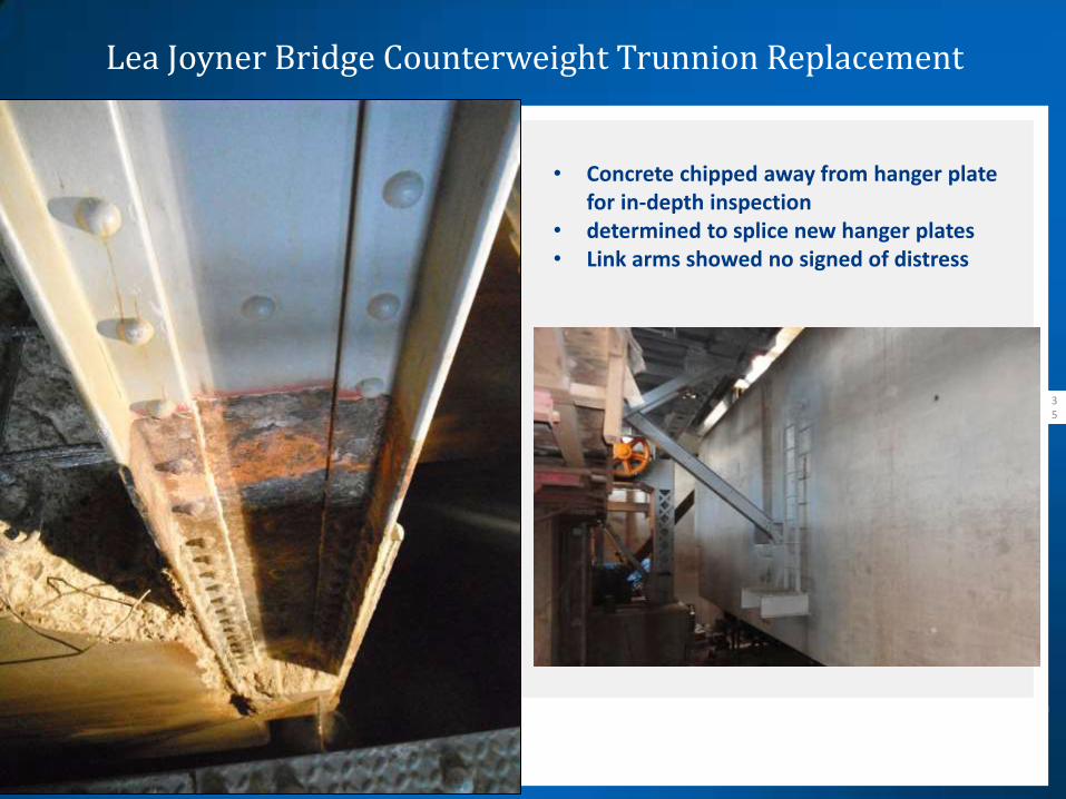
• Concrete chipped away from hanger plate for in-depth inspection
• determined to splice new hanger plates • Link arms showed no signed of distress

Counterweight Jacking
36
• Strauss design minimized bascule pier • Pier shaped to counterweight fit
Counterweight in open position Less than 1 ft to front pier wall Few inches to trunnion tower platform
Notched Portion of counterweight Fits around base of trunnion tower
Counterweight Jacking
37
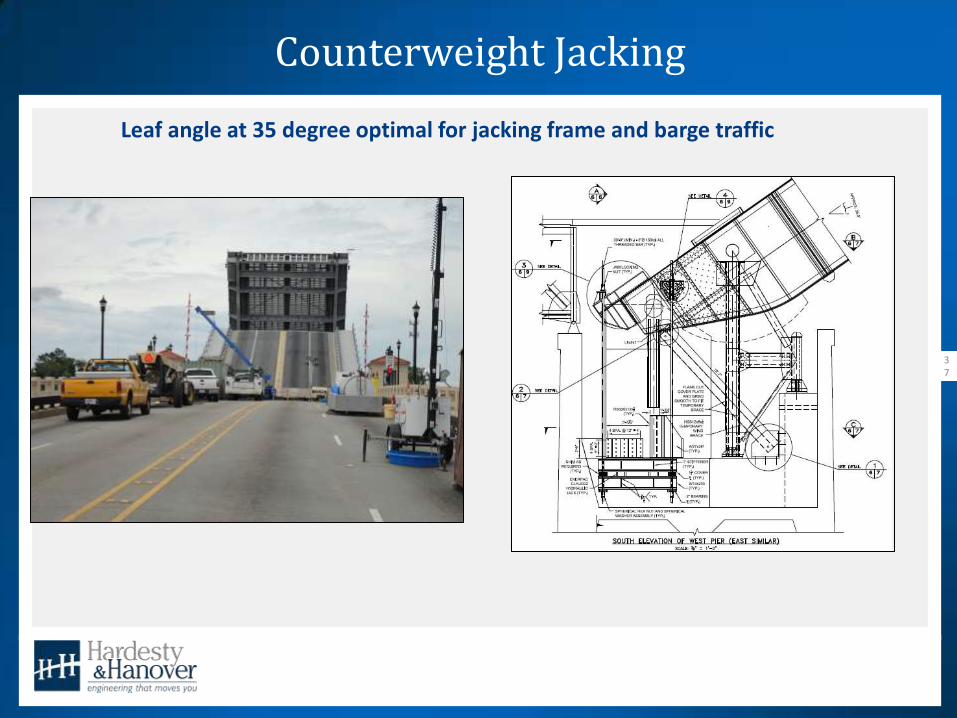
Leaf angle at 35 degree optimal for jacking frame and barge traffic

Counterweight Jacking
38
Counterweight in open position Less than 1 ft to front pier wall Few inches to trunnion tower platform
Jacking Design • 3” dia. All Thread 150 ksi Tension Rods • Attached to bracket off girder heel • Brackets positioned either side of cwt trunnion –
transfers cwt load through intended design load path • Maintains balance of leaf • Relieves load at cwt trunnion • Bracket weldments utilized existing rivet holes • Rivets removed and replaced with high strength bolts
Brackets at girder heel
Cwt Trunnion

Counterweight Jacking
39
Counterweight in open position Less than 1 ft to front pier wall Few inches to trunnion tower platform
Web Bracket • Shape of connection plate of web brackets
derived from • Spacing of rivets • Minimum bolt spacing • Number of bolts necessary for jacking
loads • Closer to main trunnion
• Designed to take double load compared to flange brackets
Web Bracket
Flange Bracket • Built up to clear back of counterweight • Designed such that tension rods cleared the
counterweight • W36x256 connected to back of girder • W14x159 attached to top flange • Welded box attached to top flange of
W14x159
Flange Bracket

Wind Load Bracing
40
Counterweight in open position Less than 1 ft to front pier wall Few inches to trunnion tower platform
Wind Load Brace • HSS 12x8 ½” (Hollow Structural Section) • Pinned (2 ½” dia.) at trunnion tower and
girder bottom flange
Counterweight Jacking
41
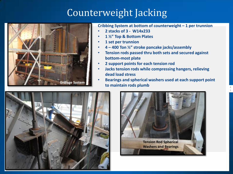
Brackets at girder heel Cribbing System at bottom of counterweight – 1 per trunnion • 2 stacks of 3 - W14x233 • 1 ½” Top & Bottom Plates • 1 set per trunnion • 4 – 400 Ton ½” stroke pancake jacks/assembly • Tension rods passed thru both sets and secured against
bottom-most plate • 2 support points for each tension rod • Jacks tension rods while compressing hangers, relieving
dead load stress • Bearings and spherical washers used at each support point
to maintain rods plumb Grillage System
Tension Rod Spherical Washers and Bearings
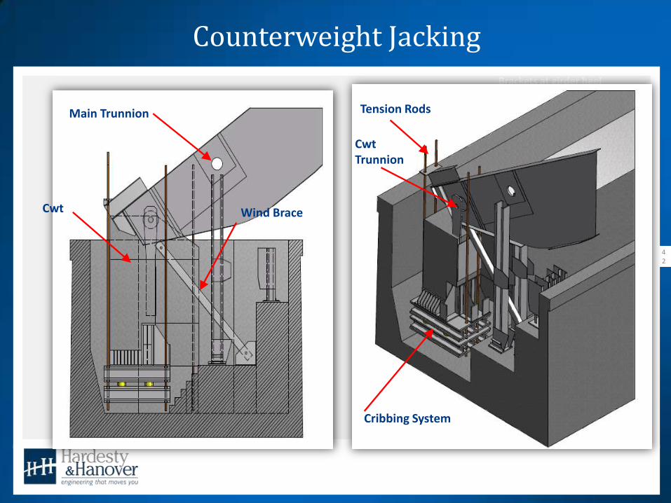
Counterweight Jacking
42
Brackets at girder heel
Cribbing System
Tension Rods
Cwt
Main Trunnion
Cwt Trunnion
Wind Brace

Counterweight Jacking
43
Hanger Plate Monitoring: • Rods in tension while hanger plate compressed to
relieve counterweight load from cwt trunnions • Actual cwt and forward leaf dead loads unknown • Dial indicators welded to girder flange monitored
vertical and horizontal displacement • Estimates of cwt dead load made throughout the
process – approx. 1.4M LB • Uneven rod spacing varied load in tension rods • Jacks were pressurized with separate manifolds in
groups of 2 jacks • Jacking performed incrementally • Shims driven at designated grillage locations to
remove load from jacks
Grillage System

Hanger Plates Cut
44
Grillage System
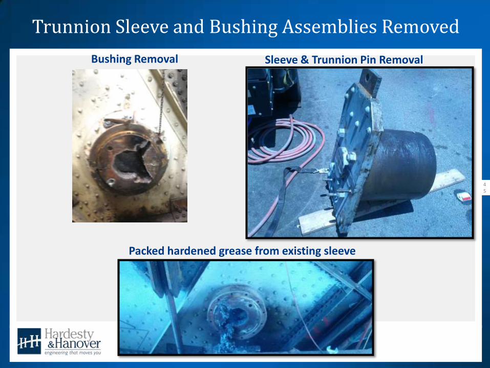
Trunnion Sleeve and Bushing Assemblies Removed
45
Grillage System
Bushing Removal Sleeve & Trunnion Pin Removal
Packed hardened grease from existing sleeve

Housing Inspection & Machining
46
Housing Field Machining
Housing Inspection & Field Machining: • Inspect ID of existing housings
• Field machine or replaced • Field line bore 1/8” larger • Shop machine final OD of new bushing • Schedule Decision - New housings ready for final machining • All four existing housings were acceptable for field
machining • Saved time by eliminating line boring the girders for new
housings - about 1 week/leaf
Housing before and after Field Machining

New CWT Trunnion Assembly
47
Grillage System
New Counterweight Trunnion Assembly Existing Counterweight Trunnion Assembly

New Bushings Installed
48
Grillage System
New Bushings Packed in Dry Ice Installed in Housing

New Hanger Plates and Sleeves
49
Grillage System
Shop Assembled Hanger Plates, Sleeves, Pin
Shop Assembled Hanger Plates, Sleeves, Pin Sleeve - RC6 Fit with Bushing

New Hanger Plates and Sleeves
50
Grillage System
New Hanger Plate Spliced to Existing Final New Counterweight Trunnion Assembly
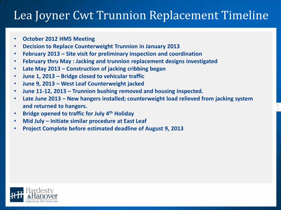
Lea Joyner Cwt Trunnion Replacement Timeline
51
Lea Joyner Bridge
• October 2012 HMS Meeting • Decision to Replace Counterweight Trunnion in January 2013 • February 2013 – Site visit for preliminary inspection and coordination • February thru May : Jacking and trunnion replacement designs investigated • Late May 2013 – Construction of jacking cribbing began • June 1, 2013 – Bridge closed to vehicular traffic • June 9, 2013 – West Leaf Counterweight jacked • June 11-12, 2013 – Trunnion bushing removed and housing inspected. • Late June 2013 – New hangers installed; counterweight load relieved from jacking system
and returned to hangers. • Bridge opened to traffic for July 4th Holiday • Mid July – Initiate similar procedure at East Leaf • Project Complete before estimated deadline of August 9, 2013
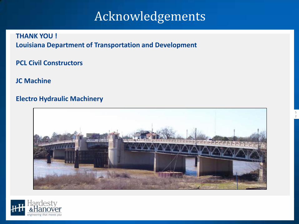
Acknowledgements
52
Lea Joyner Bridge
THANK YOU ! Louisiana Department of Transportation and Development PCL Civil Constructors JC Machine Electro Hydraulic Machinery
Discussion/Questions
53
Lea Joyner Bridge