counters and registers
DESCRIPTION
Counters and Registers. Wen-Hung Liao, Ph.D. Objectives. Understand several types of schemes used to decode different types of counters. Anticipate and eliminate the effects of decoding glitches. Compare the major differences between ring and Johnson counters. - PowerPoint PPT PresentationTRANSCRIPT
Counters and Registers
Wen-Hung Liao, Ph.D.
Objectives
Understand several types of schemes used to decode different types of counters.
Anticipate and eliminate the effects of decoding glitches.
Compare the major differences between ring and Johnson counters.
Analyze the operation of a frequency counter and of a digital clock.
Recognize and understand the operation of various types of IC registers.
Cascading BCD Counters
Figure 7-32: a multistage arrangement that counts from 000 to 999.
How does it work?
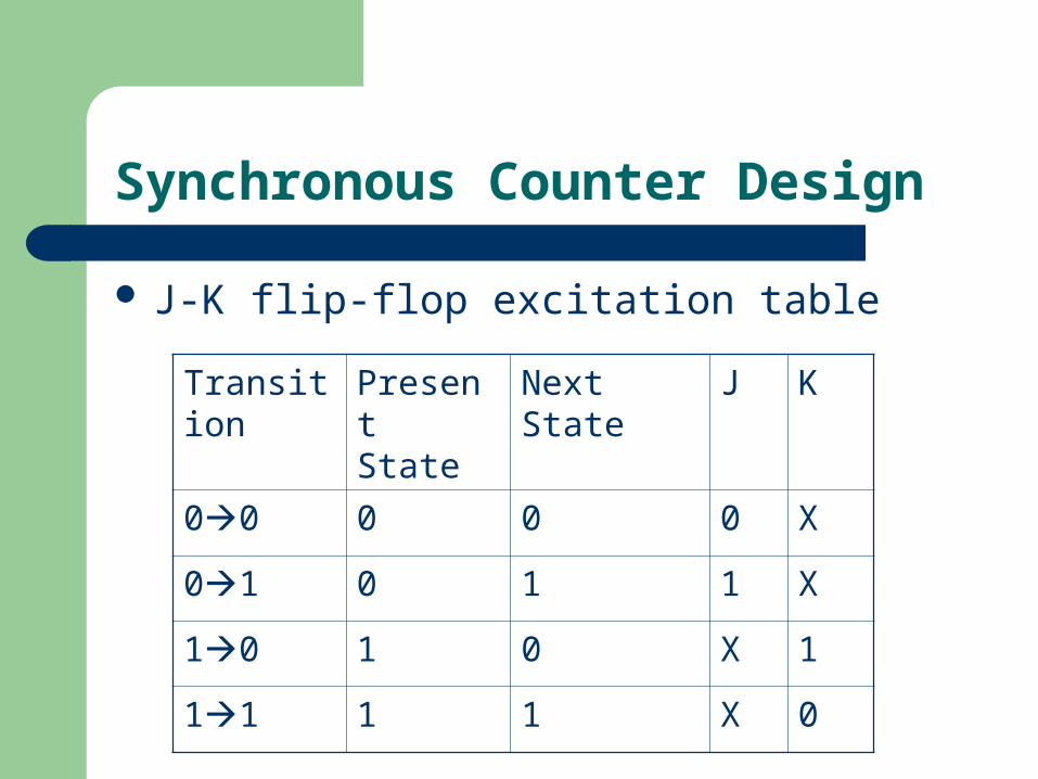
Synchronous Counter Design
J-K flip-flop excitation table
Transition Present State
Next State J K
00 0 0 0 X
01 0 1 1 X
10 1 0 X 1
11 1 1 X 0
Design Procedure
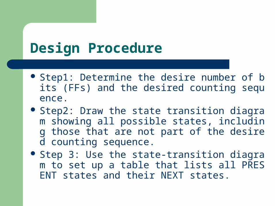
Step1: Determine the desire number of bits (FFs) and the desired counting sequence.
Step2: Draw the state transition diagram showing all possible states, including those that are not part of the desired counting sequence.
Step 3: Use the state-transition diagram to set up a table that lists all PRESENT states and their NEXT states.
Design Procedure (cont’d)
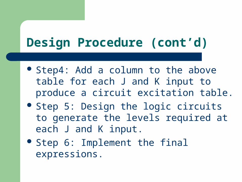
Step4: Add a column to the above table for each J and K input to produce a circuit excitation table.
Step 5: Design the logic circuits to generate the levels required at each J and K input.
Step 6: Implement the final expressions.
Example
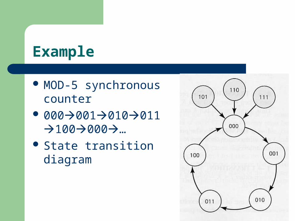
MOD-5 synchronous counter
000001010011100000…
State transition diagram
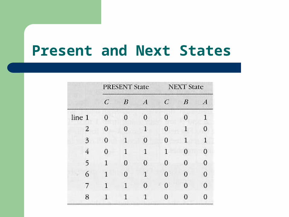
Present and Next States
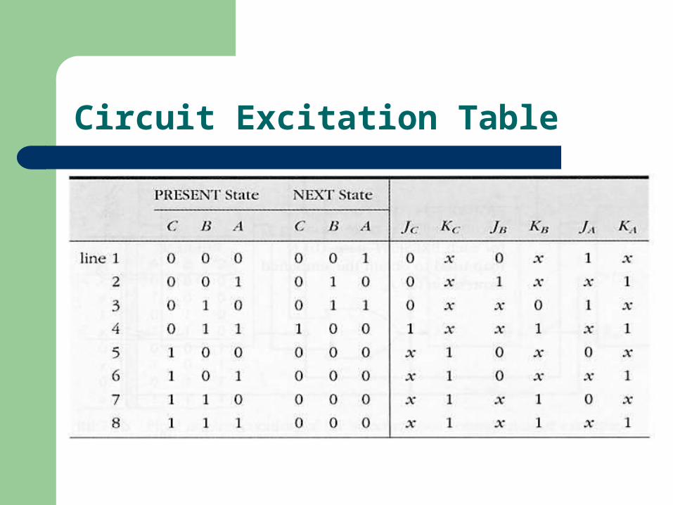
Circuit Excitation Table
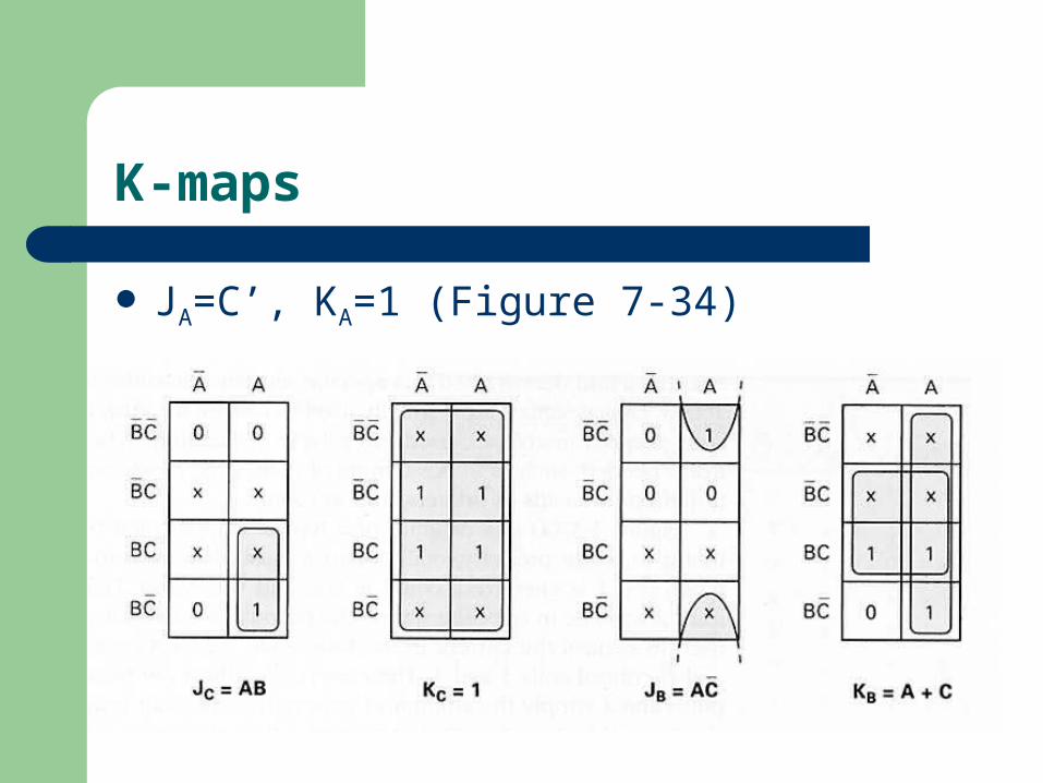
K-maps
JA=C’, KA=1 (Figure 7-34)
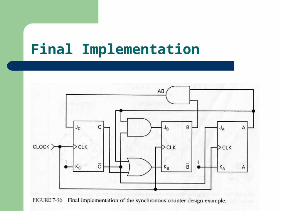
Final Implementation
Step Motor Control
A step motor is a motor that rotates in steps rather than in a continuous motion, typically 15 degrees per step.
Used in positioning of read/write heads on magnetic tapes, in controlling print heads…
Figure 7.37: CW rotation and CCW rotation. Apply the design procedure to generate the
circuit.
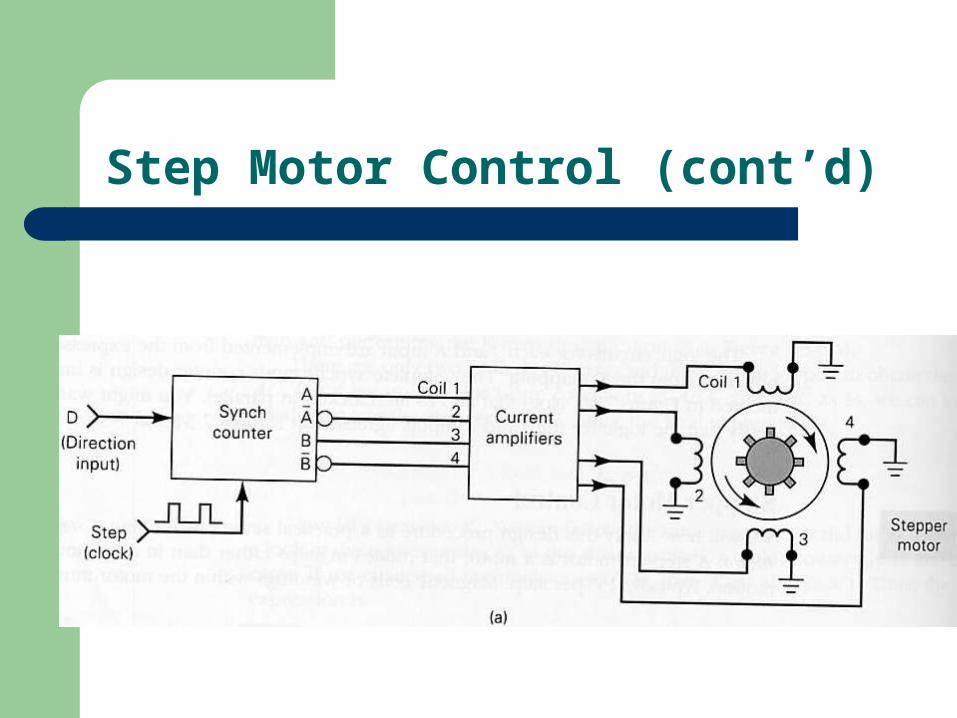
Step Motor Control (cont’d)
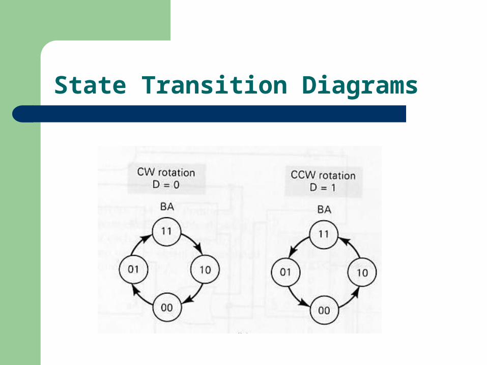
State Transition Diagrams
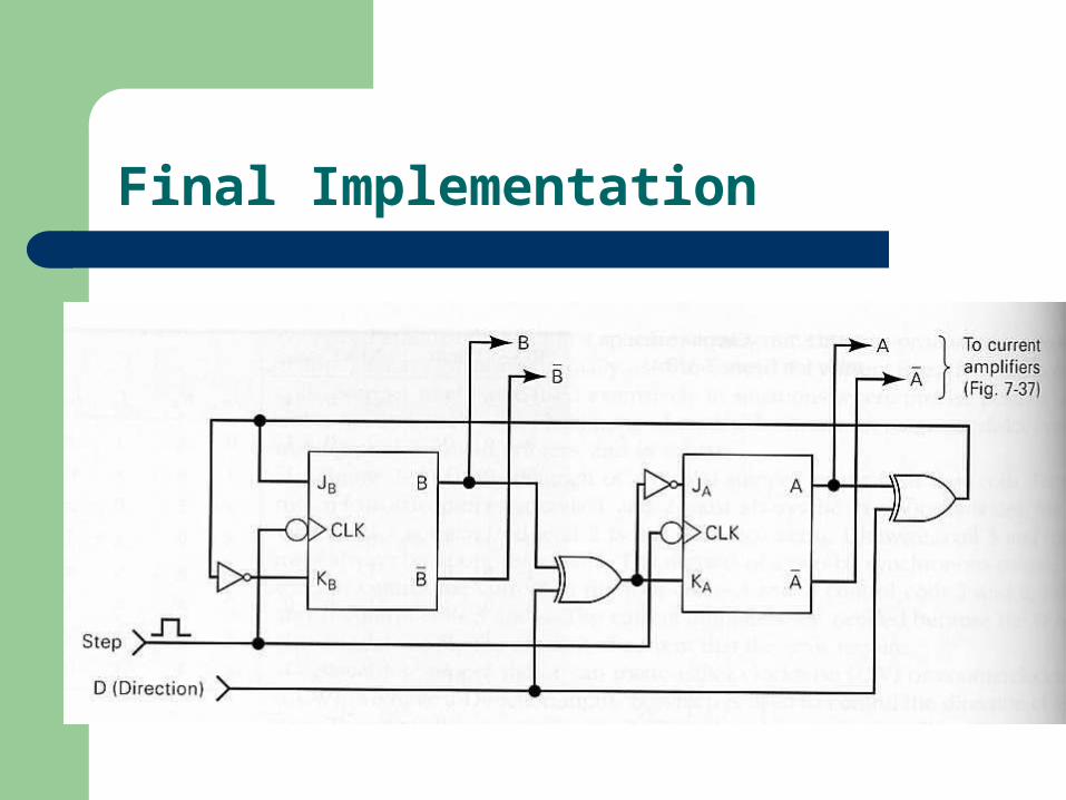
Final Implementation
Shift-Register Counters
Use feedback, output of last FF is connected back to the first FF in some way.
Ring counter: circulating shift register. See Figure 7-40. Why is it still a counter?
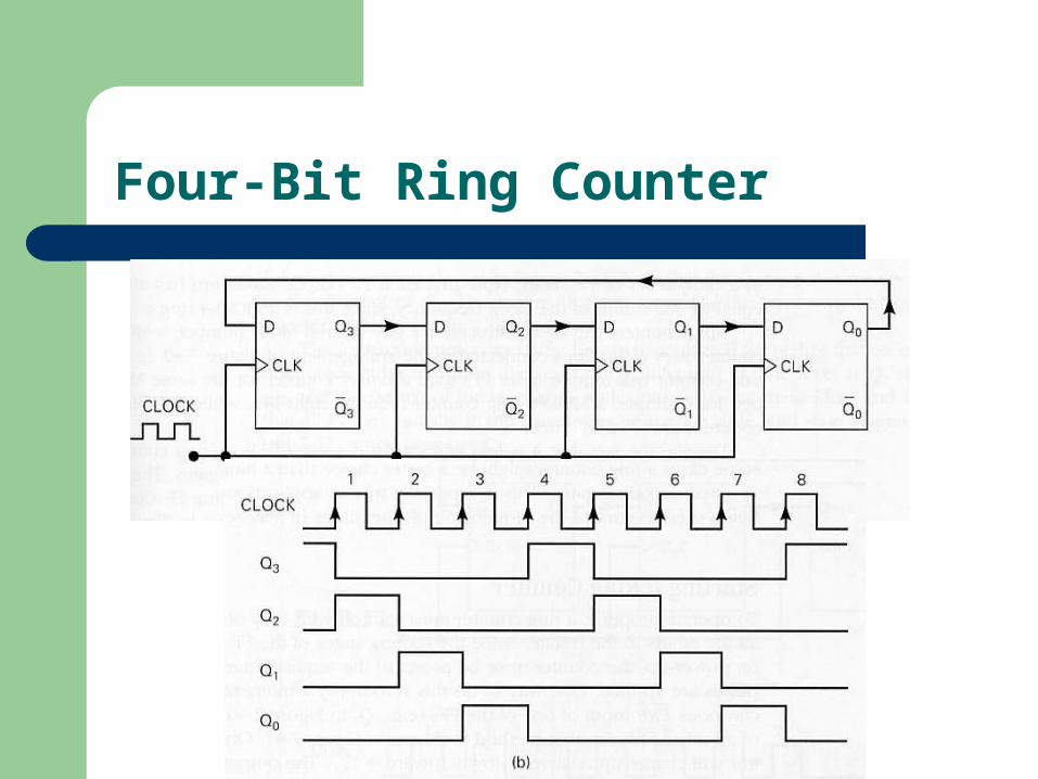
Four-Bit Ring Counter
State Transition Diagram
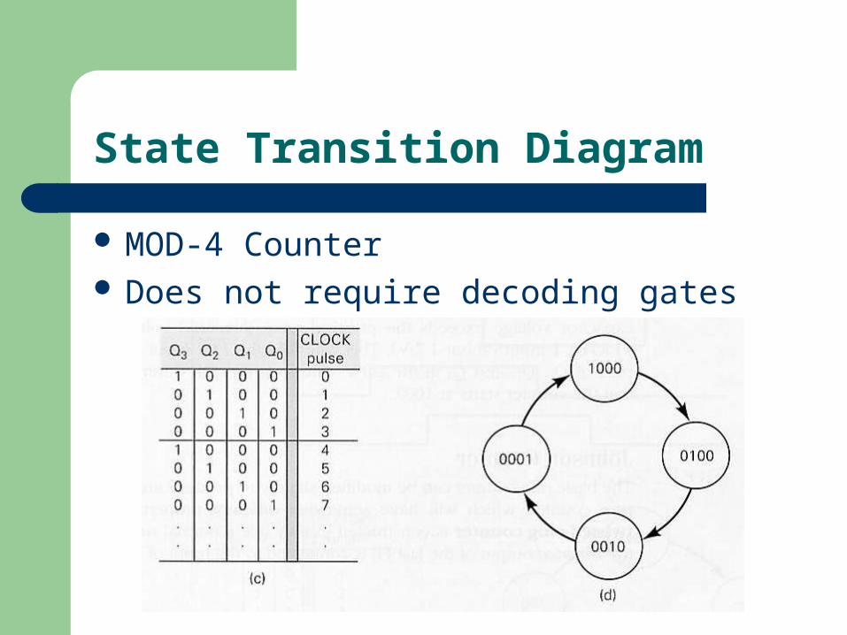
MOD-4 Counter Does not require decoding gates
Starting a Ring Counter
Start off with only one FF in the 1 state and all others in the 0 state.
Use PRE and CLR inputs and Schmitt-trigger INVERTERS(page 233).
Johnson Counter
Also known as the twisted-ring counter. Same as the ring counter except that the invert
ed output of the last FF is connected to the input of the first FF.
Counting sequence: 000100110111011001000
A MOD-6 counter (twice the number of FFs) Needs decoding gates. Figure 7-42
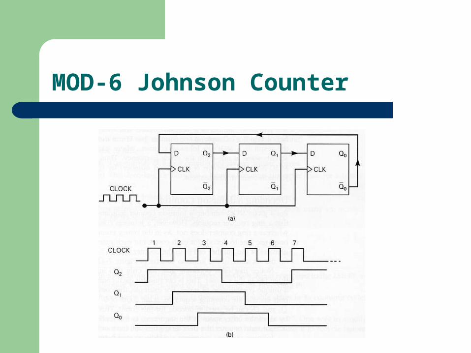
MOD-6 Johnson Counter
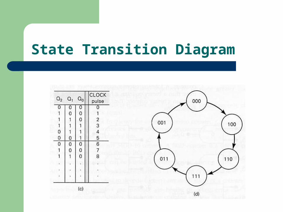
State Transition Diagram
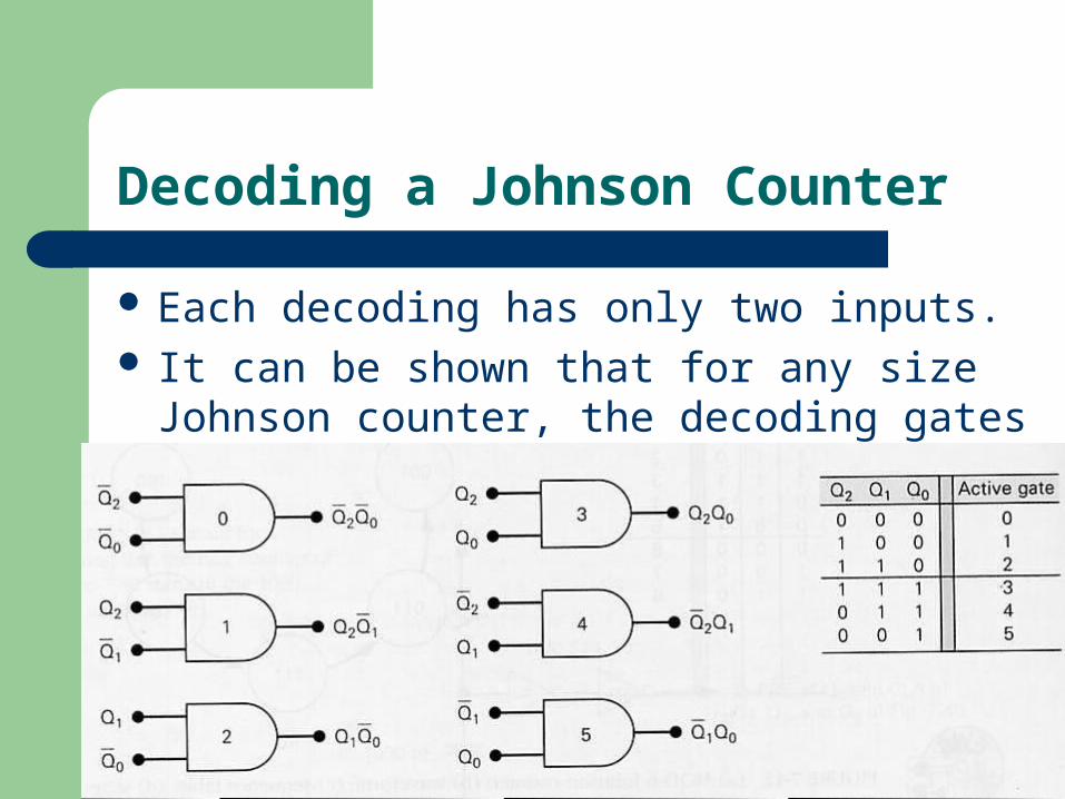
Decoding a Johnson Counter
Each decoding has only two inputs. It can be shown that for any size Johnson
counter, the decoding gates will have only two inputs.

Counter Applications
Frequency counter: a circuit that measures and displays the frequency of a signal.
Digital clock.
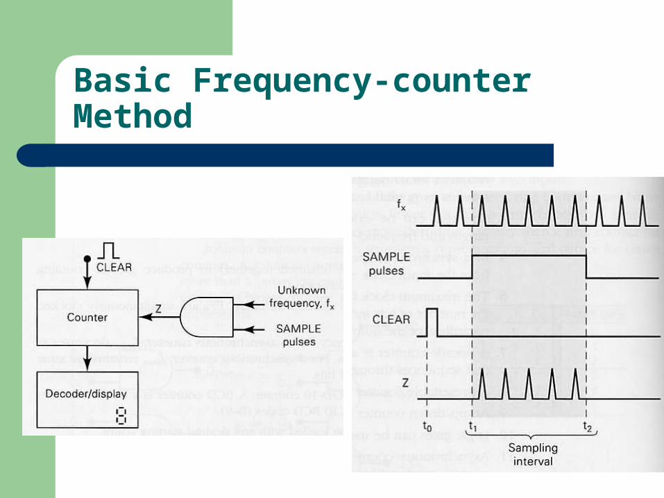
Basic Frequency-counter Method
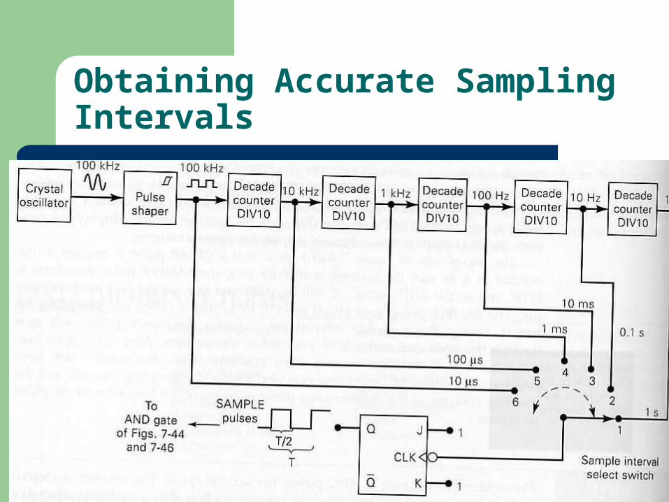
Obtaining Accurate Sampling Intervals
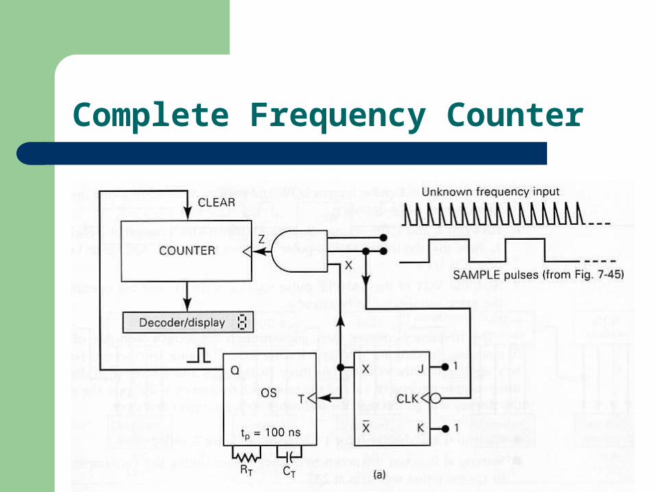
Complete Frequency Counter
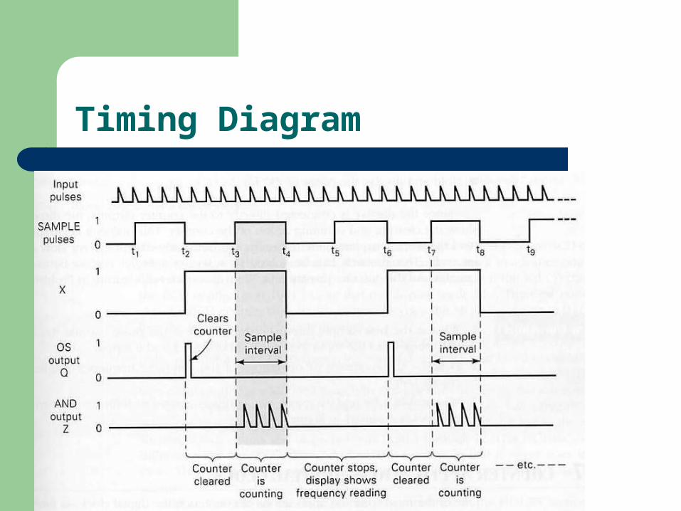
Timing Diagram
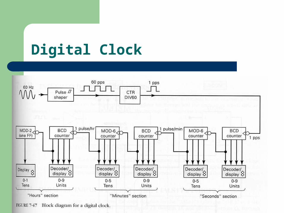
Digital Clock
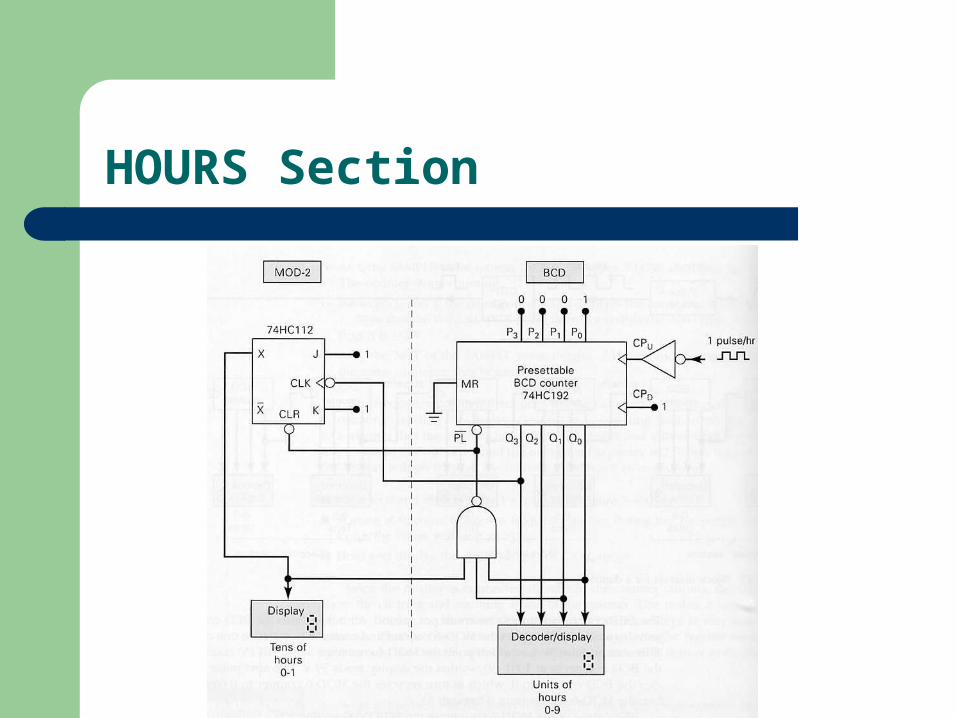
HOURS Section
Integrated-Circuit Registers
Parallel in/Parallel Out: 74174 and 74178 Serial in/Serial Out: 4731B Parallel in/Serial Out:74165,74LS165,74HC165 Serial in/Parallel Out:
74164,74LS164,74HC164