counterfeit prevention of microelectronics through...
TRANSCRIPT
Counterfeit Prevention of Microelectronics
through Covert Anti-Tamper Microcapsules
Prepared by:
Ian Markon
Faculty Advisors:
Dr. Grant Crawford
REU-SPACT Program Director
Dr. Jon Kellar
Professor of Metallurgy and Materials Science
Dr. David Boyles
Professor of Chemistry
Dr. Alfred Boysen
Professor, Department of Humanities
Program Information:
National Science Foundation
Grant EEC-1263343
Research Experience for Undergraduates
Summer 2013
South Dakota School of Mines and Technology
501 E Saint Joseph Street
Rapid City, South Dakota
2
Table of Contents
Abstract ……………………………………………………........................... 3
Introduction ……………………………………………………........................... 4
Background – Microelectronics Counterfeiting ……………........................... 4
Background – Microcapsules and Upconverting Nanoparticles ....................... 5
Objectives ……………………………………………………........................... 6
Broader Impact ……………………………………………………........................... 7
Materials and Methods ……………………………………....................................... 7
Results and Discussion ……………………………………....................................... 14
Trial 1 ……………………………………………………........................... 14
Trial 2 ……………………………………………………........................... 16
Trial 3 ……………………………………………………........................... 19
Trial 4 ……………………………………………………........................... 19
Trial 5 ……………………………………………………........................... 22
Trial 6 ……………………………………………………........................... 25
Trial 7 ……………………………………………………........................... 30
Future Work ……………………………………………………........................... 34
Conclusion ……………………………………………………........................... 35
References ……………………………………………………........................... 36
Acknowledgments ……………………………………………........................... 38
3
Abstract
The problem of microelectronics counterfeiting has been steadily growing for years, but a
recent U.S. Senate hearing on the subject has resulted in a much greater push to curtail the
problem. In an effort to produce a technological solution to this problem, a project was begun at
the South Dakota School of Mines and Technology with the goal of encapsulating upconverting
nanoparticles in breakable microcapsules to use as an anti-tamper marking on authentic
microelectronics. This portion of the project focused mainly on developing techniques to
successfully form microcapsules. Seven microencapsulation trial runs were attempted with the
result that complete microcapsules were produced in one of the trials and broken or incomplete
microcapsules in at least two other trials.
4
Introduction
Background – Microelectronics Counterfeiting
Estimates for the losses to the microelectronics (semiconductor) industry caused by
counterfeiting currently sit at about $7.5 billion/year or at least 2.5% of annual integrated circuit
sales [1]. As bad as this number is, the figure is almost misleading, for this estimate only
includes lost sales; the cost of removing and replacing counterfeits which do make their way
onto the market is easily many times higher. This considerable financial loss alone should be
enough to warrant concern, but the problem of microelectronics counterfeiting really came into
the public eye following the infiltration of counterfeit electronic components into the US military
supply chain. The senate investigation launched as a result of this revelation highlighted the
seriousness of the counterfeiting problem and led to legislation designed to provide greater
security to the US military supply chain [2]. The regulations passed after this investigation have
not fully solved the problem, however, and manufacturers and customers of microelectronics
alike are now seeking technological answers to the question of how to protect themselves from
counterfeits.
To realize a useful anti-counterfeiting technique, one must first understand the common
methods for counterfeiting. Two of the most common techniques for counterfeiting
microelectronics are sanding and blacktopping. The techniques may be used either separately or
in conjunction. Sanding is simply the process of sanding the printed or engraved identification
information off of the top of a chip (new or old) and subsequently re-printing/engraving false
information (brand, part number, manufacture date, etc.) on the newly-sanded surface.
Blacktopping is the process of covering the old identification information with a new layer of
5
black polymer designed to blend in with the rest of the chip packaging and then printing false
information on top of the new layer. When used in conjunction, sanding and blacktopping may
leave the final thickness of the chip packaging unchanged and prove very difficult to detect. [2]
Background – Microcapsules and Upconverting Nanoparticles
Microcapsules (and their smaller counterparts, nanocapsules) are a new and intriguing
invention with a large variety of applications from targeted medical imaging [3] to self-repair of
polymers [4] to conductivity restoration in electrical connections [5]. Whatever their use,
microcapsules and nanocapsules are basically hollow spheres which may be loaded with useful
cargoes to be released upon the destruction of the capsule shell.
There are several methods for creating microcapsules. One way, known as the layer by
layer (LbL) method involves using a charged particle, usually spherical in nature, as a template
on which alternating layers of positively-charged and negatively-charged polymers may be built
up. Once the shell reaches a desired thickness, the original template may be dissolved to leave a
hollow capsule. [6]
Another common method for creating microcapsules involves vigorously agitating a non-
polar liquid (possibly with the desired cargo for the final capsule suspended or dissolved within
that liquid) in the presence of water. The agitation and the inability of the two liquids to mix
cause tiny bubbles of the non-polar solution to become suspended in the polar solution, forming
an emulsion, and the addition of polymerizing agents results in the encapsulation of the tiny,
non-polar bubbles in polymer shells. [4]
6
Upconverting nanoparticles are tiny particles with dimensions of less than one
micrometer which possess the ability to convert low-wavelength (and therefore relatively low
energy) light into higher-wavelength light in the visible spectrum. Recently, a variety of highly-
luminescent sodium yttrium tetrafluoride (NaYF4) nanocrystals doped with rare-earth elements
have been identified for potential security and anti-counterfeiting applications because of their
manufacturing complexity and detection difficulty (without the proper equipment at least).
These nanoparticles/crystals may be made to be nearly invisible under normal lighting conditions
but brightly florescent under excitation by a near infrared (NIR) laser or other light source. [7]
Objectives
The goal of this research project is to create a simple and effective means to equip
authentic microelectronics with an anti-tamper coating which will fluoresce under NIR light only
if the chip packaging has been disturbed. This anti-tamper coating will be formulated to contain
microcapsules loaded with upconverting nanocrystals whose shells suppress the nanocrystals’
ability to give off light until the microcapsule shells are broken by a counterfeiting action such as
sanding. Figure 1 gives a pictorial example of this idea.

7
Figure 1. Marked Microelectronics Under
NIR Inspection.
Broader Impact
A simple and effective means for marking a microelectronic component upon its
packaging being compromised would provide a new layer of protection to the manufacturers and
purchasers of microelectronics and help keep counterfeit parts off of the market. This, in turn,
would result in legitimate manufacturers of such components reclaiming a portion of the
potential earnings which they lose to counterfeiters each year. Furthermore, the added security
to the US military supply chain would have the potential to keep faulty or malicious parts out of
the equipment and vehicles necessary to maintaining the safety and freedom of both the
servicemen/women themselves, as well as everyone who relies upon them.
Materials and Methods
A careful search of the available literature on encapsulation revealed that a very versatile
method for microencapsulation existed which utilized a cross-linked urea-formaldehyde (UF)
8
polymer for shell material. Furthermore, the microcapsules made with this method were fairly
robust thermally and mechanically. Numerous materials had already been encapsulated in such
microcapsules with great success, and, while the mechanisms governing the formation of the
microcapsules were not fully explained, the role of each component in the process was
reasonably understood. Lastly, the size of the final microcapsules produced by this process was
dependent upon the severity of the agitation of the emulsion and could therefore be easily
tailored to the chosen cargo. [8-10]
To become familiar with the UF microencapsulation process, the work of Dr. Nancy
Sottos and collaborators [4, 8-9] was used as a basis for this microencapsulation study.
Essentially, the microencapsulation process used in these papers involves stirring a quantity of
water, urea, formaldehyde, resorcinol, ammonium chloride (NH4Cl), ethylene maleic anhydride
(EMA) copolymer, and the organic liquid to be encapsulated (the encapsulant) in a beaker at
elevated temperatures in an acidic environment to allow the urea and formaldehyde to cross-link
and form shells around the encapsulant. The decision was made to reduce the total amount of
material used in each trial run (while keeping the component ratios the same) as compared to the
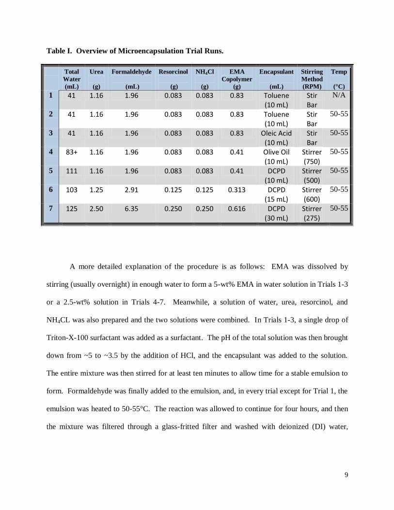
literature values to save material while learning the necessary technique. Table I provides an
overview of the materials, amounts, heating techniques, and stirring techniques and speeds used
during each of the seven microencapsulation trial runs.
9
Table I. Overview of Microencapsulation Trial Runs.
Total
Water
(mL)
Urea
(g)
Formaldehyde
(mL)
Resorcinol
(g)
NH4Cl
(g)
EMA
Copolymer
(g)
Encapsulant
(mL)
Stirring
Method
(RPM)
Temp
(°C)
1 41 1.16 1.96 0.083 0.083 0.83 Toluene (10 mL)
Stir Bar
N/A
2 41 1.16 1.96 0.083 0.083 0.83 Toluene (10 mL)
Stir Bar
50-55
3 41 1.16 1.96 0.083 0.083 0.83 Oleic Acid (10 mL)
Stir Bar
50-55
4 83+ 1.16 1.96 0.083 0.083 0.41 Olive Oil (10 mL)
Stirrer (750)
50-55
5 111 1.16 1.96 0.083 0.083 0.41 DCPD (10 mL)
Stirrer (500)
50-55
6 103 1.25 2.91 0.125 0.125 0.313 DCPD (15 mL)
Stirrer (600)
50-55
7 125 2.50 6.35 0.250 0.250 0.616 DCPD (30 mL)
Stirrer (275)
50-55
A more detailed explanation of the procedure is as follows: EMA was dissolved by
stirring (usually overnight) in enough water to form a 5-wt% EMA in water solution in Trials 1-3
or a 2.5-wt% solution in Trials 4-7. Meanwhile, a solution of water, urea, resorcinol, and
NH4CL was also prepared and the two solutions were combined. In Trials 1-3, a single drop of
Triton-X-100 surfactant was added as a surfactant. The pH of the total solution was then brought
down from ~5 to ~3.5 by the addition of HCl, and the encapsulant was added to the solution.
The entire mixture was then stirred for at least ten minutes to allow time for a stable emulsion to
form. Formaldehyde was finally added to the emulsion, and, in every trial except for Trial 1, the
emulsion was heated to 50-55°C. The reaction was allowed to continue for four hours, and then
the mixture was filtered through a glass-fritted filter and washed with deionized (DI) water,
10
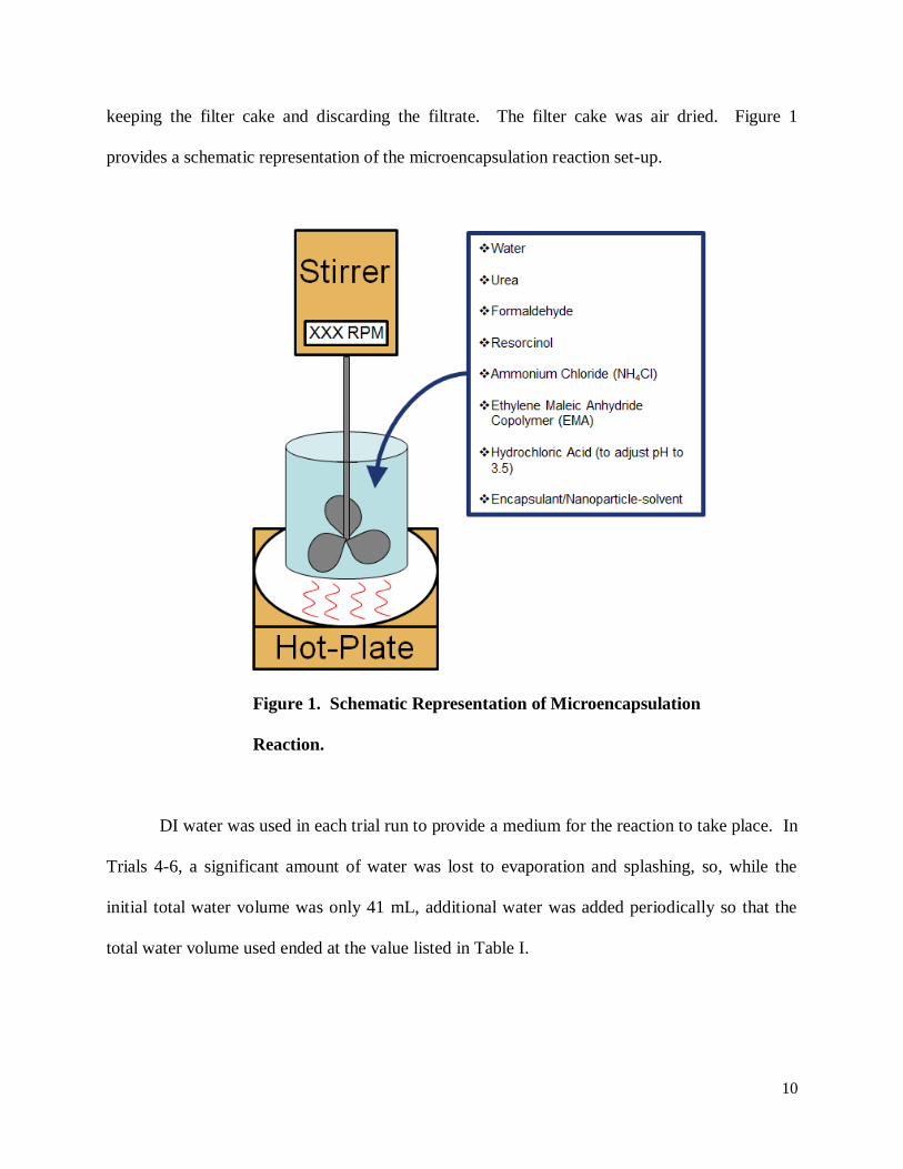
keeping the filter cake and discarding the filtrate. The filter cake was air dried. Figure 1
provides a schematic representation of the microencapsulation reaction set-up.
Figure 1. Schematic Representation of Microencapsulation
Reaction.
DI water was used in each trial run to provide a medium for the reaction to take place. In
Trials 4-6, a significant amount of water was lost to evaporation and splashing, so, while the
initial total water volume was only 41 mL, additional water was added periodically so that the
total water volume used ended at the value listed in Table I.
11
Reagent-grade urea was purchased from Fisher Scientific and 37% formaldehyde
(formalin) was acquired from the SDSM&T chemical storeroom. These two materials are
primarily responsible for polymerizing to form the outer shell of the microcapsules. Information
in the literature suggests that the first stage of the polymerization reaction results in a low-
molecular weight, water-soluble pre-polymer which deposits at the interface between the water
and the encapsulant. The deposited material continues to cross-link and eventually becomes a
smooth, solid shell capable of holding the encapsulant without leakage. The second stage of the
polymerization reaction results in the water-soluble pre-polymer continuing to grow in molecular
weight until it precipitates out of solution as little nano-beads which may adhere to the smooth
microcapsule shell under acidic conditions. [8]
Resorcinol was purchased from Sigma Aldrich and NH4Cl was acquired from the
SDSM&T chemical storeroom. Resorcinol is seen as allowing the UF polymerization reaction to
take place in the presence of the encapsulant. Ammonium chloride, on the other hand, is
intended to accelerate the condensation of the UF. [10]
Ethylene maleic anhydride copolymer (molecular weight: 400,000) was donated by
Vertellus®. The EMA copolymer plays a wide variety of roles in the microencapsulation
process. EMA:
accelerates the emulsion process
stabilizes the emulsion
accelerates capsule wall formation
aids in the dispersion of the microcapsules
12
In addition, EMA is thought to play an active role in the UF polymerization reaction, but the
exact nature of that role is not understood. [10]
Hydrochloric acid was used to lower the starting pH of the reaction to approximately 3.5
as the polymerization reaction is catalyzed by an acidic environment. From this starting value,
the pH of the emulsion drops down to approximately 2.2 as the reaction progresses. [8]
A variety of encapsulants were used in the seven trial runs. Toluene and oleic acid were
acquired from the SDSM&T chemical storeroom, olive oil (Safeway Select® brand, extra virgin)
was purchased from a local store, and dicylopentadiene (DCPD) was purchased from Fisher
Scientific. Initial trials focused on trying to encapsulate a material not used in any of Sottos’s
articles but which may easily dissolve/disperse the upconverting nanoparticles (toluene, oleic
acid, olive oil) while later trials focused solely on trying to replicate the originally published
results (DCPD).
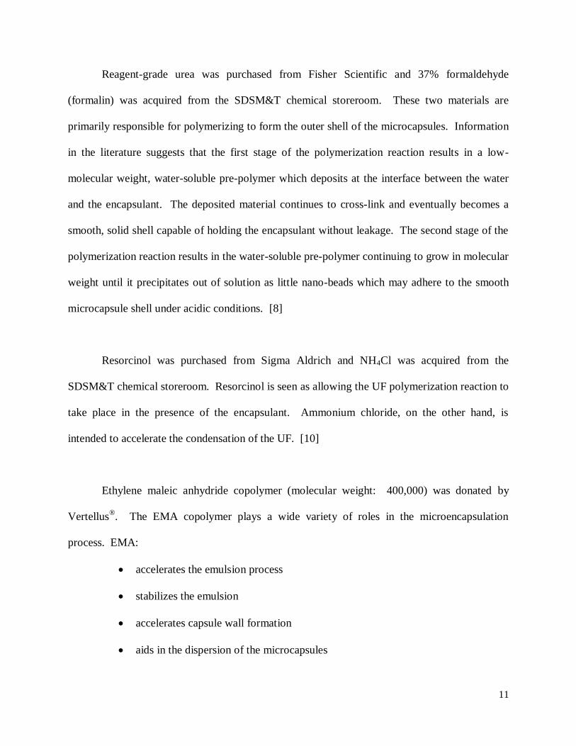
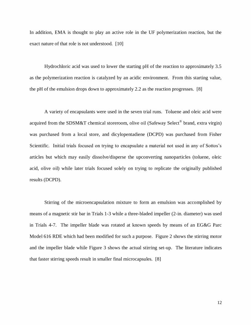
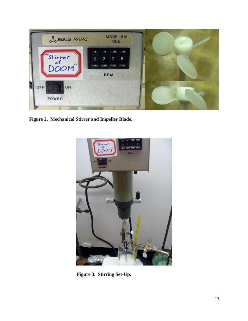
Stirring of the microencapsulation mixture to form an emulsion was accomplished by
means of a magnetic stir bar in Trials 1-3 while a three-bladed impeller (2-in. diameter) was used
in Trials 4-7. The impeller blade was rotated at known speeds by means of an EG&G Parc
Model 616 RDE which had been modified for such a purpose. Figure 2 shows the stirring motor
and the impeller blade while Figure 3 shows the actual stirring set-up. The literature indicates
that faster stirring speeds result in smaller final microcapsules. [8]
13
Figure 2. Mechanical Stirrer and Impeller Blade.
Figure 3. Stirring Set-Up.
14
In the first trial, heating was accomplished by means of a thermal well, but this heating
method proved too difficult to accurately regulate. Trials 2-7 used a hot-plate for temperature
control. A variety of temperatures were used in the literature, but they generally ranged from 50
to 60°C. [4] [8] [10]
The filter cake produced in each trial run was generally examined visually, but a field
emission scanning electron microscope (SEM) was usually necessary to properly evaluate the
results of each trial. Evaluation of the filter cake was performed by breaking the cake in half and
lightly pressing a piece of carbon tape against the new fracture surface. The tape and attached
filter cake material was then coated in a thin layer of gold by vapor deposition to prevent the
specimen from charging under SEM examination. An electron accelerating voltage of 3 kV was
used for best quality images.
Results and Discussion
Trial 1
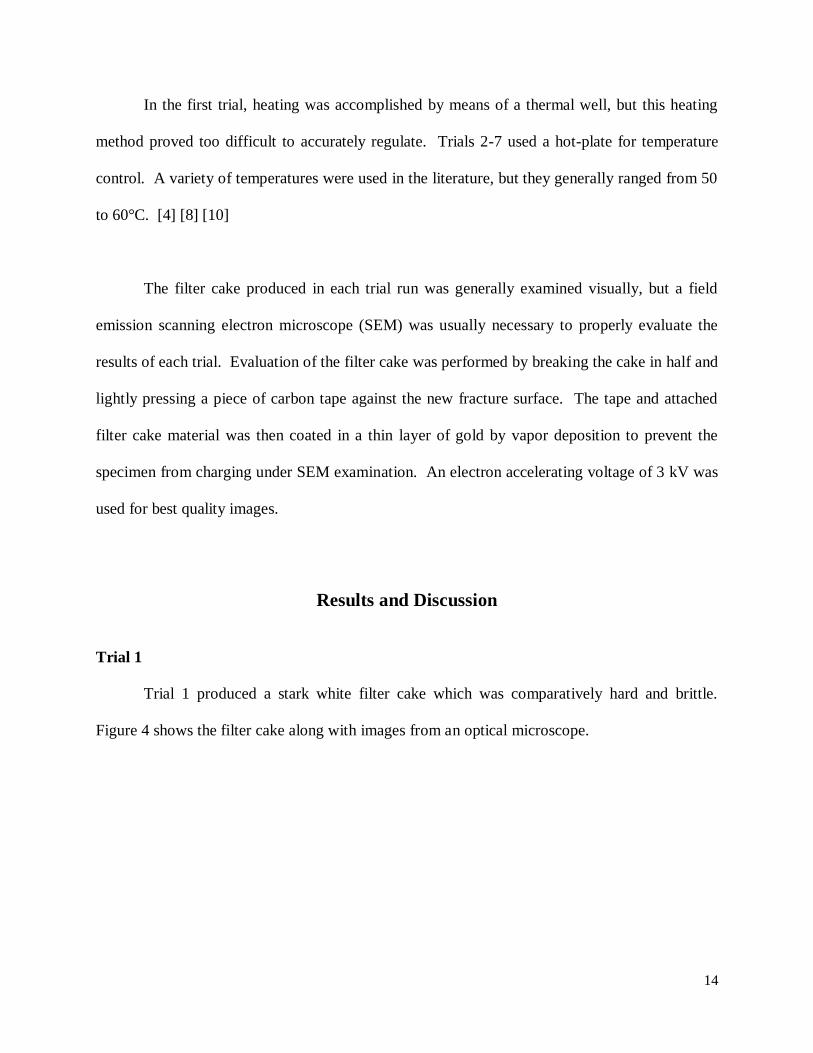
Trial 1 produced a stark white filter cake which was comparatively hard and brittle.
Figure 4 shows the filter cake along with images from an optical microscope.
15
Figure 4. Trial Batch 1. A) Picture of filter cake. B) and C) Optical microscope images of
filter cake particles.
Trial Batch 1 appeared to take on the bright white color of the EMA copolymer while no
trace of pale yellow toluene remained. The uncontrolled heating from the thermal well is
believed to have reached temperatures sufficient to volatilize the toluene, thus removing it from
the emulsion altogether and making the formation of microcapsules impossible. SEM images of
later trial batches suggest that UF particles did form in this and all other trials (a theory
substantiated by the optical microscope images), but the UF polymer did not form capsules, only
nano-beads.
A B C
16
Trial 2
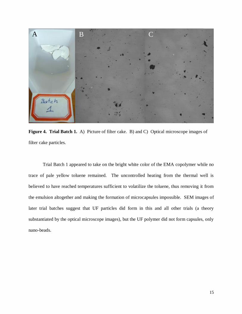
Trial 2 attempted to correct the heating problems encountered in Trial 1 by use of a hot-
plate for heating. Trial 2 produced a yellow-white filter cake which was somewhat softer than
Trial Batch 1. Figure 5 shows the filter cake along with an image from an optical microscope,
and Figures 6 and 7 show a pair of SEM images of the trial results.
Figure 5. Trial Batch 2. A) Picture of filter cake. B)
Optical microscope image of filter cake particles.
A B
17
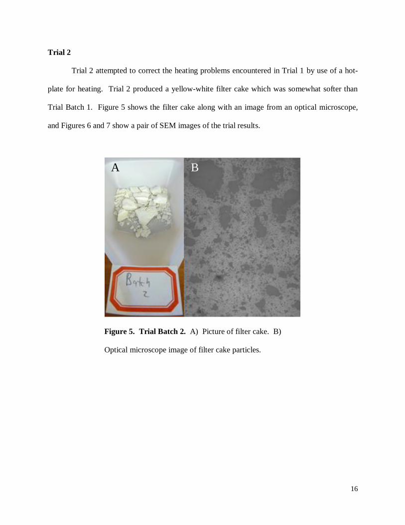
Figure 6. SEM Image of Trial Batch 2 at 1000X.
18
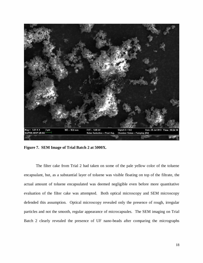
Figure 7. SEM Image of Trial Batch 2 at 5000X.
The filter cake from Trial 2 had taken on some of the pale yellow color of the toluene
encapsulant, but, as a substantial layer of toluene was visible floating on top of the filtrate, the
actual amount of toluene encapsulated was deemed negligible even before more quantitative
evaluation of the filter cake was attempted. Both optical microscopy and SEM microscopy
defended this assumption. Optical microscopy revealed only the presence of rough, irregular
particles and not the smooth, regular appearance of microcapsules. The SEM imaging on Trial
Batch 2 clearly revealed the presence of UF nano-beads after comparing the micrographs

19
obtained to the SEM images of microcapsules found in [8], but no microcapsules were evident in
this examination either.
Trial 3
It was hypothesized that toluene may have been an unsuitable encapsulant which was
actually capable of dissolving the UF polymer, making the encapsulation of toluene impossible.
Consequently, Trial 3 was an attempt to encapsulate oleic acid. The upconverting nanoparticles
intended for encapsulation are capped in oleic acid to prevent them from growing beyond the
nano scale, and so oleic acid was considered a potential solvent/dispersant for the nanocrystals
and therefore a viable encapsulant.
Visually, Trial 3 produced results almost identical to Trial 2. The oleic acid was seen to
separate from the mixture to form its own layer on top of the water (and other components of the
process) even before the mixture could be filtered. Trial 3 was therefore also deemed a failure
and discarded before further evaluation was attempted.
Trial 4
Trial 4 saw considerable changes to the microencapsulation process. The use of the
surfactant, Triton-X-100, was abandoned as the role of EMA copolymer as a surfactant was
confirmed. The difficulty of dissolving enough EMA copolymer in water to form a 5-wt% EMA
in water solution was also addressed by resorting to the use of a 2.5 wt% EMA solution. The
encapsulant was changed again from oleic acid to olive oil because concern had been expressed
20
that the polar head groups of oleic acid may prohibit the deposition of UF pre-polymer at the
encapsulant-water interface.
The most substantial change to the process was the discontinuation of agitation by a
magnetic stir bar in favor of agitation by an impeller. Concern had been expressed that the stir
bar could be grinding up potential early microcapsules as it spun against the bottom of the
beaker.
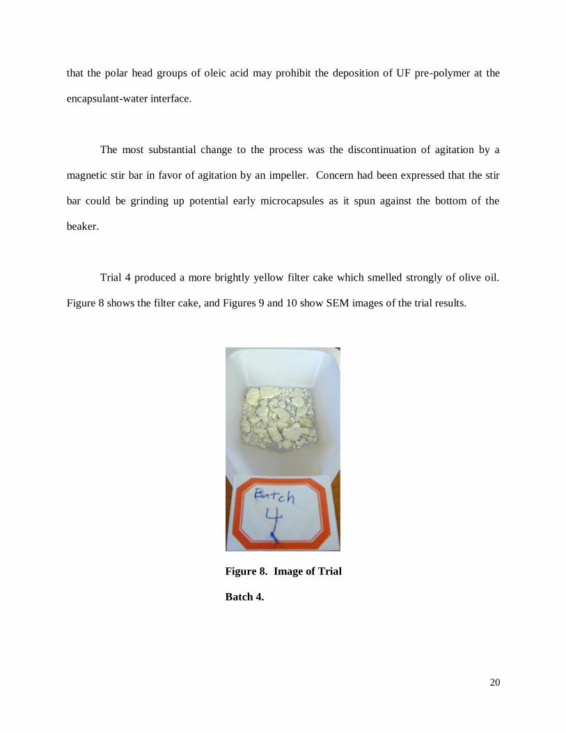
Trial 4 produced a more brightly yellow filter cake which smelled strongly of olive oil.
Figure 8 shows the filter cake, and Figures 9 and 10 show SEM images of the trial results.
Figure 8. Image of Trial
Batch 4.

21
Figure 9. SEM Image of Trial Batch 4 at 1130X.
22
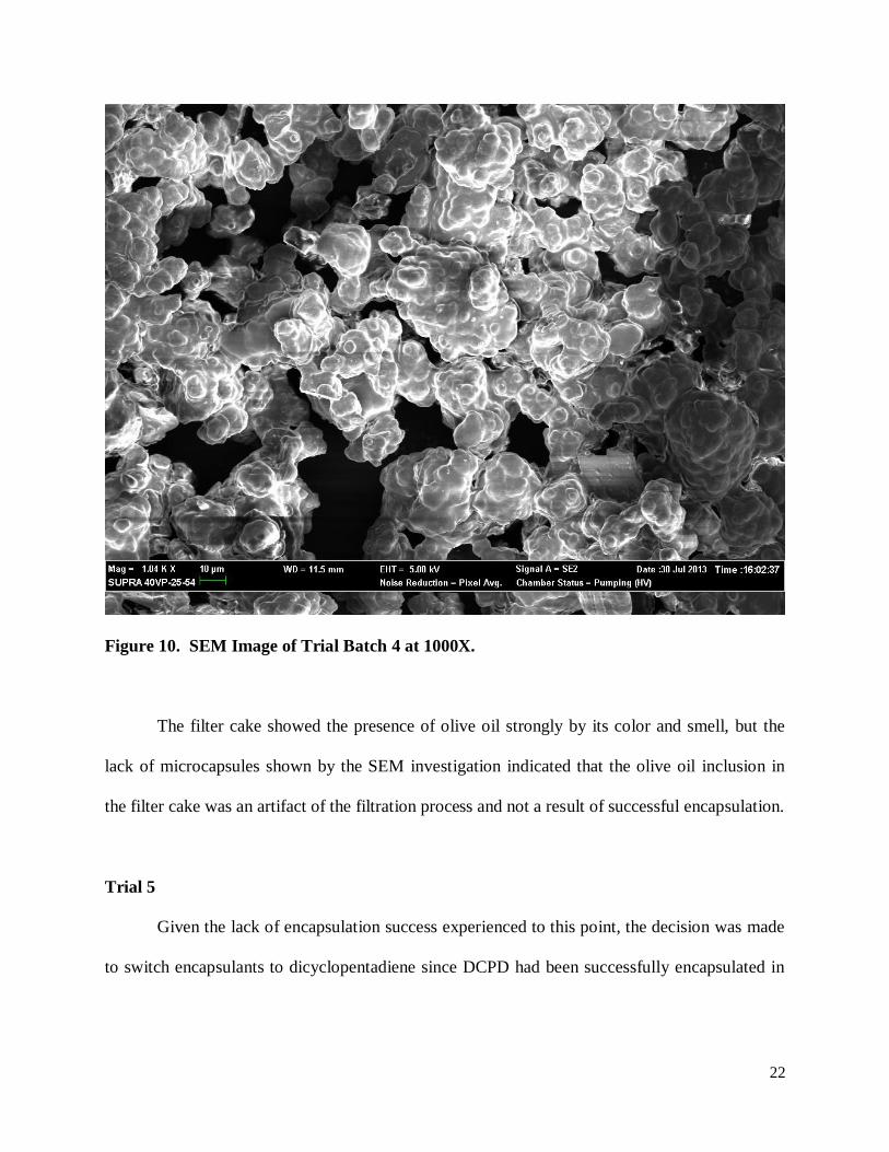
Figure 10. SEM Image of Trial Batch 4 at 1000X.
The filter cake showed the presence of olive oil strongly by its color and smell, but the
lack of microcapsules shown by the SEM investigation indicated that the olive oil inclusion in
the filter cake was an artifact of the filtration process and not a result of successful encapsulation.
Trial 5
Given the lack of encapsulation success experienced to this point, the decision was made
to switch encapsulants to dicyclopentadiene since DCPD had been successfully encapsulated in
23
numerous works of literature ([4] [5] [8] [9] [12]). The stirring speed was also reduced for fear
of agitating the microcapsules too vigorously during their fragile, formative period.
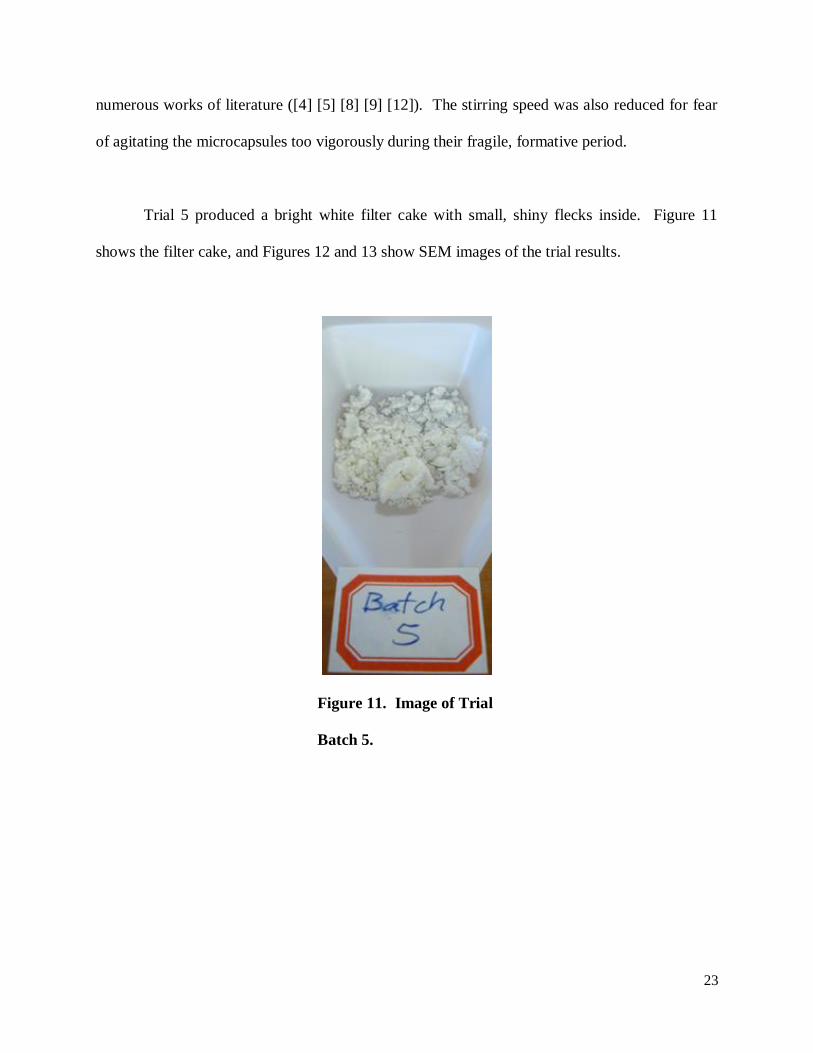
Trial 5 produced a bright white filter cake with small, shiny flecks inside. Figure 11
shows the filter cake, and Figures 12 and 13 show SEM images of the trial results.
Figure 11. Image of Trial
Batch 5.
24
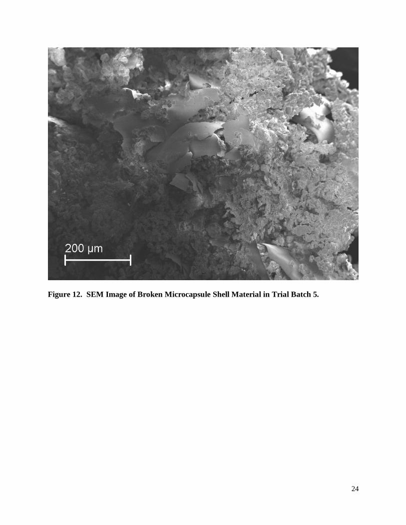
Figure 12. SEM Image of Broken Microcapsule Shell Material in Trial Batch 5.
25
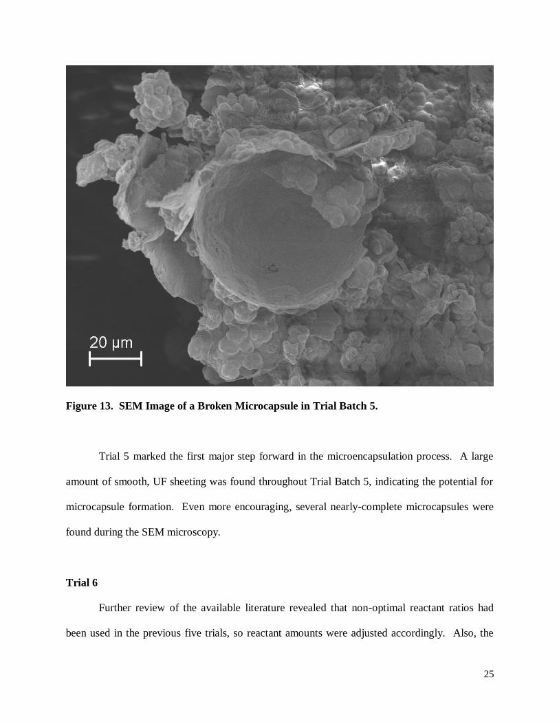
Figure 13. SEM Image of a Broken Microcapsule in Trial Batch 5.
Trial 5 marked the first major step forward in the microencapsulation process. A large
amount of smooth, UF sheeting was found throughout Trial Batch 5, indicating the potential for
microcapsule formation. Even more encouraging, several nearly-complete microcapsules were
found during the SEM microscopy.
Trial 6
Further review of the available literature revealed that non-optimal reactant ratios had
been used in the previous five trials, so reactant amounts were adjusted accordingly. Also, the
26
total volume of the reaction was increased and a taller beaker put into service in attempts to
reduce the amount of material being lost to splashing and evaporation by submerging the
impeller beneath more liquid and catching whatever liquid continued to splash.
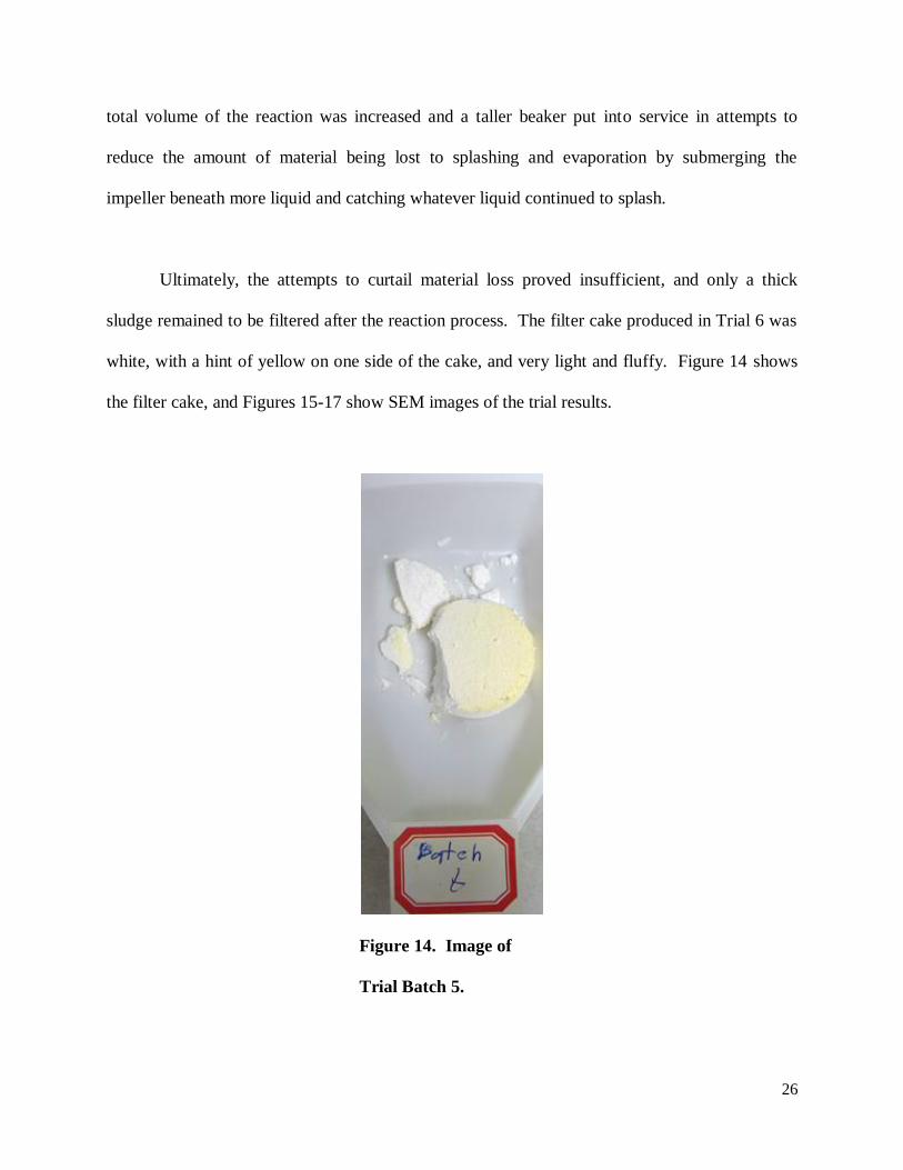
Ultimately, the attempts to curtail material loss proved insufficient, and only a thick
sludge remained to be filtered after the reaction process. The filter cake produced in Trial 6 was
white, with a hint of yellow on one side of the cake, and very light and fluffy. Figure 14 shows
the filter cake, and Figures 15-17 show SEM images of the trial results.
Figure 14. Image of
Trial Batch 5.
27
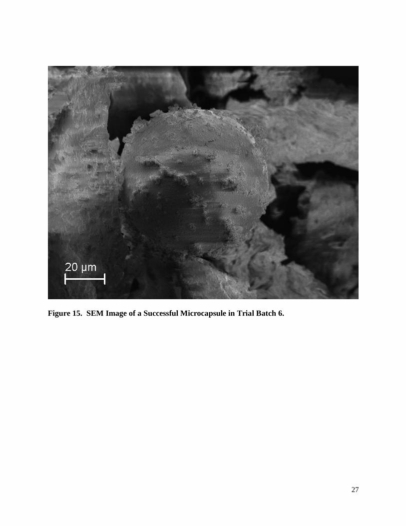
Figure 15. SEM Image of a Successful Microcapsule in Trial Batch 6.
28
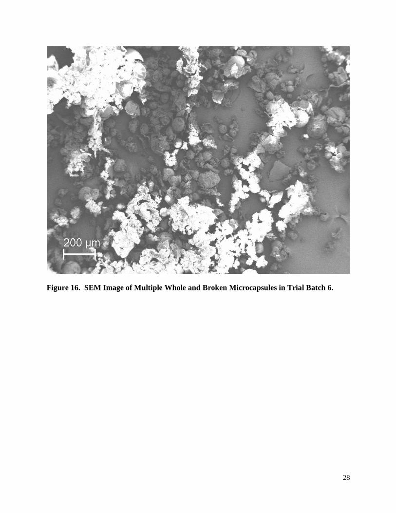
Figure 16. SEM Image of Multiple Whole and Broken Microcapsules in Trial Batch 6.
29
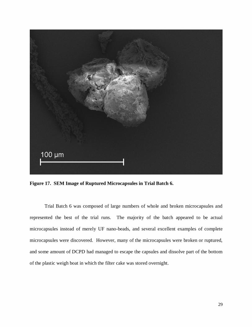
Figure 17. SEM Image of Ruptured Microcapsules in Trial Batch 6.
Trial Batch 6 was composed of large numbers of whole and broken microcapsules and
represented the best of the trial runs. The majority of the batch appeared to be actual
microcapsules instead of merely UF nano-beads, and several excellent examples of complete
microcapsules were discovered. However, many of the microcapsules were broken or ruptured,
and some amount of DCPD had managed to escape the capsules and dissolve part of the bottom
of the plastic weigh boat in which the filter cake was stored overnight.
30
Trial 7
The final trial run, Trial 7, attempted to address the problem of large numbers of broken
microcapsules by further increasing the volume of material used in the experiment (to better
cover the impeller) and by slowing down the rotational speed of the impeller. Both of these
changes were intended to reduce the forces on the microcapsules as they attempted to form.
However, too much formaldehyde was mistakenly added to the reaction (the correct amount
should have been 5.82 mL instead of the 6.35 mL which was actually used), and this mistake
may have been responsible for the poor outcome of this trial.
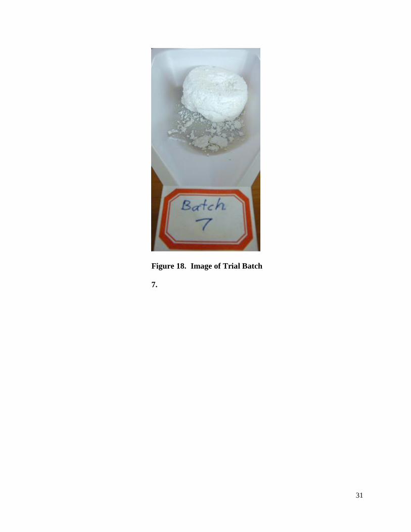
Trial 7 produced a stark white filter cake with a feel similar to the filter cake from Trial 6.
Figure 18 shows the filter cake, and Figures 19 and 20 show SEM images of the trial results.
31
Figure 18. Image of Trial Batch
7.
32
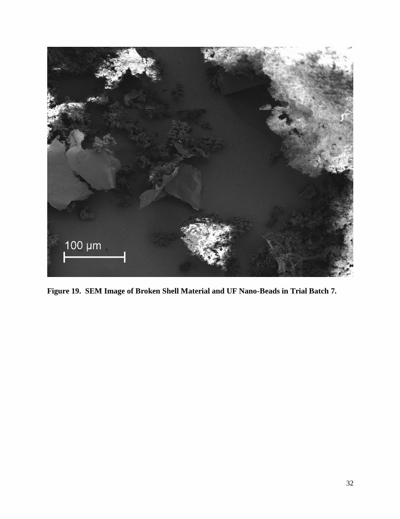
Figure 19. SEM Image of Broken Shell Material and UF Nano-Beads in Trial Batch 7.
33
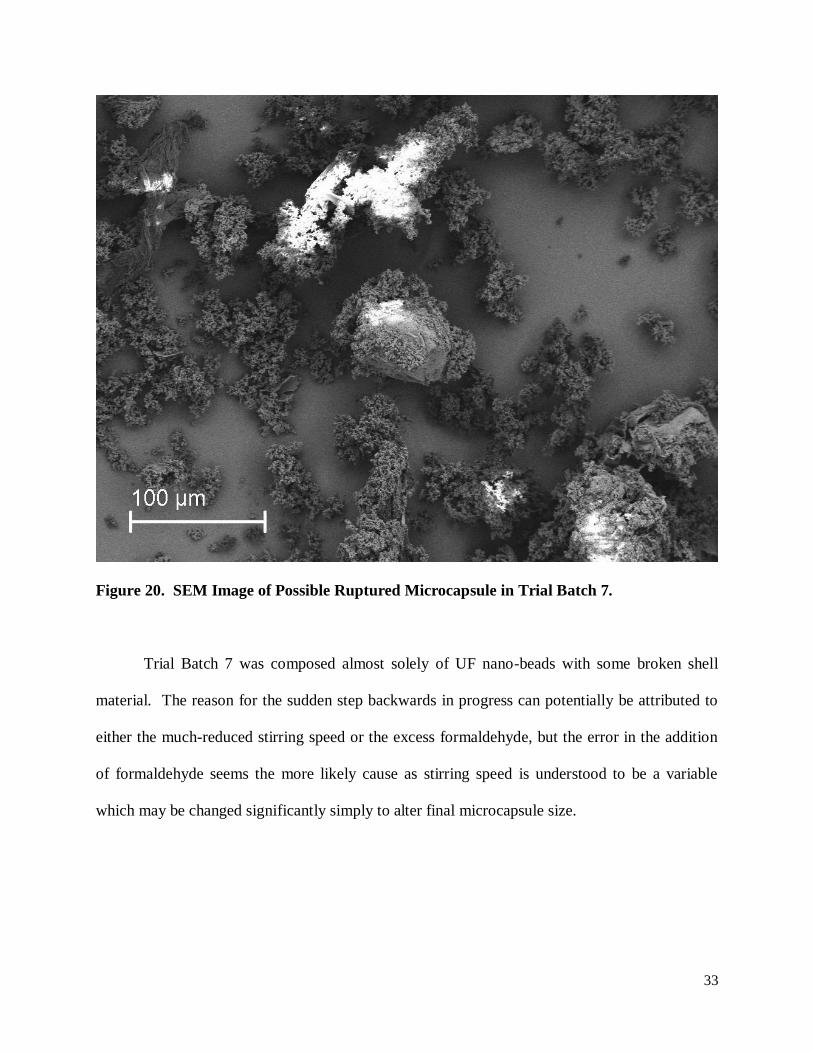
Figure 20. SEM Image of Possible Ruptured Microcapsule in Trial Batch 7.
Trial Batch 7 was composed almost solely of UF nano-beads with some broken shell
material. The reason for the sudden step backwards in progress can potentially be attributed to
either the much-reduced stirring speed or the excess formaldehyde, but the error in the addition
of formaldehyde seems the more likely cause as stirring speed is understood to be a variable
which may be changed significantly simply to alter final microcapsule size.
34
Future Work
Much work remains to be done before viable, nanoparticle-loaded microcapsules may
even be tested for effectiveness in microelectronics, let alone put into service. Of particular
concern is that the oleic acid-capped nanocrystals planned for use in this project do not readily
dissolve or disperse in DCPD. This means that even when microcapsules may be formed
reliably using DCPD as the encapsulant, the process may need to be changed to accommodate a
different encapsulant which can dissolve/disperse the nanoparticles.
The author holds out hope that a simple readjustment of the urea-formaldehyde ratio back
to the ratio used in Trial 6 should allow the other parameters used in Trial 7 to produce large
numbers of whole microcapsules. Following this work, the encapsulants used in Trials 1-4 could
be re-evaluated for effectiveness as encapsulants, or another suitable encapsulant which can
dissolve/disperse the upconverting nanoparticles must be determined.
The final evaluation of loaded microcapsules in/on microelectronics may be
accomplished in a variety of ways. The addition of loaded microcapsules into the
thermoplastic/thermoset which is used to form the housing for many microelectronics
components should be investigated and the thermal and mechanical stability of the microcapsules
in such an environment evaluated. As an alternative to using the microcapsules as an additive to
the microelectronics housing, the effectiveness of loaded microcapsules as part of a surface
coating should be investigated.
35
Conclusion
Much progress was made in developing techniques with which to perform
microencapsulation at SDSM&T, but much work remains before the final objective of this
project may be completed. Fully-formed microcapsules were produced in one trial run, and at
least two other trial runs showed evidence of broken or incomplete microcapsules. Once a
reliable method for producing microcapsules is developed, the challenges of encapsulating
upconverting nanoparticles and equipping real microelectronics with the loaded microcapsules
may be addressed.
36
References
1. Koushanfar, F., Fazzari, S., McCants, C., Bryson, W., Sale, M., Song, P., & Potkonjak,
M. (2012, June). Can eda combat the rise of electronic counterfeiting. 49th annual design
automation conference dac '12, San Fransisco, CA.
2. Hearing to receive testimony on the committee’s investigation into counterfeit electronic
parts in the department of defense supply chain. 110th Cong. 1-68 (2011)
3. Gil, P. R., del Mercato, L. L., del Pino, P., Munoz-Javier, A., & Parak, W. J. (2008).
Nanoparticle-modified polyelectrolyte capsules. Nanotoday, 3(3-4), 12-21.
4. White, S. R., Sottos, N. R., Geubelle, P. H., Moore, J. S., Kessler, M. R., Sriram, S. R.,
Brown, E. N., & Viswanathan, S. (2001). Autonomic healing of polymer composites.
Nature, 409 (6822), 794-797.
5. Odom, S. A., Caruso, M. M., Finke, A. D., Prokup, A. M., Ritchey, J. A., Leonard, J. H.,
White, S. R., & Sottos, N. R., Moore, J. S. (2010). Restoration of conductivity with ttf-
tcnq charge-transfer salts. Advanced Functional Materials, 20, 1721-1727.
6. Caruso, F., Caruso, R. A., & Mohwald, H. (1998). Nanoengineering of inorganic and
hybrid hollow spheres by colloidal templating. Science, 282(5391), 1111-1114.
7. Blumenthal, T., Meruga, J., May, P. S., Kellar, J., Cross, W., Ankireddy, K., Vunnam, S.,
& Luu, Q. N. (2012). Patterned direct-write and screen-printing of nir-to-visible
upconverting inks for security applications. Nanotechnology, (23).
8. Brown, E. N., Kessler, M. R., Sottos, N. R., & White, S. R. (2003). In situ
poly(urea_formaldehyde) microencapsulation of dicyclopentadiene. Journal of
Microencapsulation, 20(6), 719-730.
9. Blaiszik, B. J., Caruso, M. M., McIlroy, D. A., Moore, J. S., White, S. R., & Sottos, N. R.
(2008). Microcapsules filled with reactive solutions for self-healing materials. Polymer,
50(4), 990-997.
10. Dietrich, K., Herma, H., Nastke, R., Bonatz, E., & Teige, W. (1989). Amin resin
microcapsules. Acta Polymerica, 40(4), 243-251.
11. Ashby, M., Ferreira, P., & Schodek, D. (2009). Nanomaterials, nanotechnologies, and
design. Burlington, MA: Elsevier.
12. Blaiszik, B. J., Sottos, N. R., & White, S. R. (2008). Nanocapsules for self-healing
materials. Science Direct, 68, 978-986.

37
13. Meruga, J. M., Cross, W. M., May, P. S., Luu, Q., Crawford, G. A., & Kellar, J. J.
(2012). Security printing of covert quick response codes using upconverting nanoparticle
inks. Nanotechnology, (23).
38
Acknowledgments
The author would like to first of all thank the National Science Foundation for funding
this program and Drs. Crawford and Kellar for organizing and running the program as a whole in
addition to being excellent advisors to me personally. The technical contributions of Drs. Boyles
and May were incredibly appreciated too, as was Jesse Hinricher’s assistance in running the
microencapsulation experiments. A very big thanks is also due to Dr. Boysen for his tireless
work to make sure that all of the participants in the program had a very good report to show after
their efforts this summer. Drs. Cross and West deserve special note as well for helping to make
the program such a fun and enjoyable experience, and a final thank-you goes out to all of my
fellow REU students for being such wonderful coworkers.