corrosion behavior of radial friction welded supermartensitic stainless steel pipes
TRANSCRIPT
Materials and Design 65 (2015) 318–327
Contents lists available at ScienceDirect
Materials and Design
journal homepage: www.elsevier .com/locate /matdes
Corrosion behavior of radial friction welded supermartensitic stainlesssteel pipes
http://dx.doi.org/10.1016/j.matdes.2014.09.0030261-3069/� 2014 Elsevier Ltd. All rights reserved.
⇑ Corresponding author. Tel.: +55 16 33518507; fax: +55 16 33518258.E-mail addresses: [email protected], [email protected] (C.A. Della
Rovere).
C.A. Della Rovere a,⇑, J.M. Aquino b, C.R. Ribeiro a, R. Silva a, N.G. Alcântara a, S.E. Kuri a
a Department of Materials Engineering, Federal University of São Carlos, Rodovia Washington Luis, Km 235, 13565-905 São Carlos, SP, Brazilb Department of Chemistry, Federal University of São Carlos, Rodovia Washington Luis, Km 235, 13565-905 São Carlos, SP, Brazil
a r t i c l e i n f o a b s t r a c t
Article history:Received 2 June 2014Accepted 3 September 2014Available online 19 September 2014
Keywords:Stainless steelWeldingPolarizationAcid corrosionPitting corrosion
Supermartensitic stainless steel pipes were radial friction (RF) welded and their corrosion propertieswere determined based on electrochemical tests. Measurements were performed on samples taken fromthe base metal (BM), weld interface, and consumable ring (CR) of the RF weldment. The corrosion prop-erties are discussed in terms of their resulting metallurgical microstructure. In acid media, RF weldmentregions presented better corrosion performance than the tempered structure of the BM. The Cr carbideprecipitation that occurs during tempering causes substantial depletion of Cr, while d-ferrite formationduring welding cycle decreases the pitting corrosion resistance of the material.
� 2014 Elsevier Ltd. All rights reserved.
1. Introduction
Since the early 90s, the oil industry has been promoting thedevelopment of new corrosion resistant alloys for onshore and off-shore pipeline applications. In this context, supermartensitic stain-less steel (SMSS) was introduced to bridge the gap between thecorrosion performance of carbon steels/conventional martensiticstainless steels and the more expensive duplex materials, whileproviding a larger application domain in terms of temperature,CO2 + H2S content and chloride concentration. In addition, thisnew class of martensitic stainless steels combines low productioncost, ease of heat treatment, good mechanical properties andimproved weldability. These advantages have let to the widespreaduse of SMSSs in the manufacture of oil country tubular goods,which include special seamless pipes for drilling, casing, and tub-ing for application in oil and gas wells operating under moderatelycorrosive conditions [1–3].
The main metallurgical difference between conventional mar-tensitic stainless steels and SMSSs is that the latter contain up to3% more molybdenum (Mo) and up to 6% more nickel (Ni). Mo isadded to improve the resistance to sulfide stress cracking andlocalized corrosion, while Ni is added to stabilize austenite (c) athigh temperatures, preventing the formation of d-ferrite. Carbon(C) content levels are reduced to as little as 0.01 wt.% to improve
weldability. In addition, some microalloying with titanium (Ti)and/or niobium (Nb) have been employed to stabilize residual Cand nitrogen (N) and prevent the precipitation of chromium (Cr)– rich carbonitrides, which impairs the corrosion resistance ofsteel, and to produce a finer microstructure with superior mechan-ical properties [4–6].
Today, the major issues and challenges of SMSSs have to dowith their weldability and the resulting mechanical and corrosionperformance of the welded material, as well as the development offast, reliable, economic welding processes that minimize or evendispense with expensive and time-consuming post-weld heattreatments. In this context, several new and advanced processeshave been investigated as alternatives to conventional weldingprocess for SMSSs [7–10]. Omura et al. [7] applied laser weldingto produce thin wall seam welded pipes of SMSS with excellentcorrosion properties due to the rapid solidification of the weldmetal, which had neither precipitation nor segregation. Theseauthors also found that the laser welded pipes showed superiorcorrosion resistance than those produced by conventional seamwelding processes such as gas tungsten arc welding (GTAW) andelectric resistance welding (ERW). Aquino and co-workers [8,9]have studied the corrosion behavior of SMSS welded joints pro-duced with or without matching consumables, using electronbeam welding (EB) process. No PWHT was applied. In both cases,because of the rapid heating and cooling involved in the EBW pro-cess, the authors have verified an improvement in the corrosionresistance from the base metal to the weld metal in the EB weld-ment. However, Bala Srinivasan and co-workers [10] have reported
C.A. Della Rovere et al. / Materials and Design 65 (2015) 318–327 319
that the weld metal of SMSS EB welded joints is prone to embrit-tlement under the conditions of hydrogen charging due to the highhardness and strength levels presented by the microstructure inthis region. In summary, much attention is still focused on estab-lishing optimal welding procedures for SMSSs and on understand-ing the behavior of these weldments in different applications.
Radial friction (RF) welding is a variant of the friction weldingprocess which was developed by TWI as a ‘‘one-shot’’ joining tech-nique for pipelines, offering significant advantages over conven-tional welding process, e.g. an extremely fast welding time ofless than thirty seconds, no requirement for operator skills, highweld quality, high reproducibility and the possibility of joining dis-similar materials. In addition, many of the metallurgical problemsassociated with fusion welding processes can be avoided, since RFwelding is a solid state joining process [11–16]. In regard to thedevelopment of this welding process, there are some works worthmentioning. For example, RF welding experiments were first pro-posed and carried out by Nicholas et al. [11] using steel pipes.Dunkerton and co-workers [12] applied RF welding to duplexstainless steel pipes and obtained a satisfactory weld quality. Asound weld formation with no defects was observed in the trans-verse section of the weldment. In addition, the authors have alsohighlighted that RF welding is a suitable procedure for offshoreapplication. Torster et al. [13] studied the metallurgical andmechanical properties of Ti–6Al–4V–0.1Ru (wt.%) riser pipesjoined by RF welding and indicated that the RF welded joints fulfillthe basic requirements for a future use in the installation ofTi–6Al–4V–0.1Ru (wt.%) production risers. Luo et al. [14] haveadopted RF welding to copper/high carbon steel dissimilar metalsand studied the interfacial features of this dissimilar welding joint.They reported that a smooth line occurs in the central weldinginterface and a good welding seam is formed. Very recently, thestudies by Rovere et al. [15,16] revealed that the RF welding pro-cess can be applied to SMSS pipes and high quality SMSS (defect-free) welds can be reproducibly made with mechanical propertiesclosely matching those of the base material, without requiring apost-weld heat treatment.
Despite the above cited advantages and the excellent potentialof RF welding for joining pipes offshore, this solid-state weldingprocess is not yet widely applied. Moreover, the current literaturecontains very few studies about the corrosion behavior of RFwelded pipes, so additional studies are of vital importance to fur-ther develop and expand the industrial application of this weldingprocess. In this work, the corrosion behavior and microstructuralcharacteristics of the different regions of SMSS pipes welded byRF were investigated separately, i.e., the base metal, consumablering and weld interface. The corrosion properties were studiedbased on potentiodynamic polarization and double loop electro-chemical potentiokinetic reactivation (DL-EPR) measurements.The resulting metallurgical microstructures were analyzed by opti-cal microscopy (OM), scanning electron microscopy (SEM) andX-ray diffraction (XRD).
2. Experimental Procedure
2.1. Material
The SMSS RF welded seamless pipe segments had an outerdiameter of 168.3 mm and a wall thickness of 14.3 mm. RF weldswere produced using a consumable ring machined from a heavywall pipe. Both the pipe material (BM) and the consumable ring(CR) consisted of a commercial high alloy SMSS (UNS S41426) inquenched and tempered condition, and their chemical composi-tions are described in Table 1.
The RF welding process was performed by putting together twobevelled pipes, which were secured by clamps to prevent any addi-
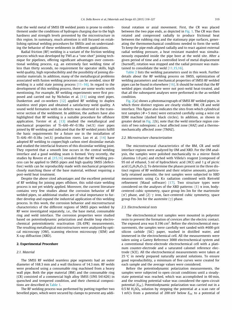
tional rotation or axial movement. First, the CR was placedbetween the two pipe ends, as depicted in Fig. 1. The CR was thenrotated and compressed radially to produce frictional heatbetween the rubbing ring and the stationary pipe surfaces, gener-ating the thermomechanical conditions needed to form the weld.To keep the pipe ends aligned radially and to react against externalradial welding pressure, a heat resistant mandrel was simulta-neously expanded inside the pipe bore at the weld site. After agiven period of time and a controlled level of metal displacement(burnoff), rotation was stopped and the radial pressure was main-tained to consolidate the weld [11,15,16].
Table 2 lists the welding parameters used in this work. Furtherdetails about the RF welding process on SMSS, optimization ofwelding parameters and mechanical properties of SMSS RF weldedpipes can be found in elsewhere [16]. It should be noted that the RFwelded pipes studied here were not post-weld heat-treated, andthat all the subsequent analyses were performed in the as-weldedcondition.
Fig. 2(a) shows a photomacrograph of SMSS RF welded pipes, inwhich three distinct regions are clearly visible: BM, CR and weldinterface. This figure also indicates the sites from which cylindricaltest samples (U = 5 mm) were extracted carefully using a wire cutEDM machine (dashed black circles). In addition, as shown ingreater detail in Fig. 2(b), note that the weld interface region con-sists of two subregions: a heat affected zone (HAZ) and a thermo-mechanically affected zone (TMAZ).
2.2. Microstructure characterization
The microstructural characteristics of the BM, CR and weldinterface regions were analyzed by OM and XRD. For the OM anal-ysis, the samples were polished mechanically to a mirror finish(alumina 1.0 lm) and etched with Villela’s reagent [composed of95 ml of ethanol, 5 ml of hydrochloric acid (HCl) and 1 g of picricacid (C6H3N3O7)]. To determine the phases present in the three dis-tinct regions of RF weldment and their relative amounts, particu-larly retained austenite, the test samples were subjected to XRDmeasurements using Cu Ka radiation combined with Rietveldrefinement (Maud software) [17]. Two structure types wereconsidered on the analyses of the XRD patterns: (1) a iron, body-centered cubic symmetry, space group Im-3m for the martensite(a’) phase, and (2) c iron, face-centered cubic symmetry, spacegroup Fm-3m for the austenite (c) phase.
2.3. Electrochemical tests
The electrochemical test samples were mounted in polyesterresin to prevent the formation of crevices after the electric contact.The exposed area was 0.196 cm2. Before the electrochemical mea-surements, the samples were carefully wet sanded with #600-gritsilicon carbide (SiC) paper, washed in distilled water, andimmersed in the electrochemical cell. All the measurements weretaken using a Gamry Reference 3000 electrochemical system anda conventional three-electrode electrochemical cell with a plati-num counter-electrode and a saturated calomel reference elec-trode (SCE). All the electrochemical measurements were taken at25 �C in newly prepared naturally aerated solutions. To ensuregood reproducibility, a minimum of five curves were created foreach sample and the average values were considered.
Before the potentiodynamic polarization measurements, thesamples were subjected to open circuit conditions until a steady-state potential was reached, which was accomplished in 60 min,and the resulting potential value was considered the open-circuitpotential (EOC). Potentiodynamic polarization was carried out in a0.5 M H2SO4 solution by stepping the potential at a scan rate of1 mV/s from a potential of 200 mV below EOC to a potential of
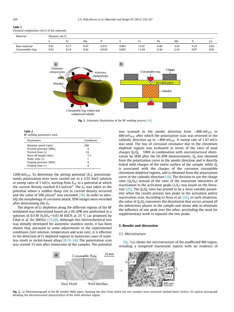
Table 1Chemical composition (wt.%) of the materials.
Material Element (wt.%)
C Si Mn P S Cr Ni Mo Ti Cu
Base material 0.01 0.17 0.47 0.012 0.001 12.01 6.40 2.42 0.10 0.02Consumable ring 0.01 0.14 0.42 0.010 0.001 11.94 6.36 2.42 0.07 0.02
Fig. 1. Schematic illustrations of the RF welding process [16].
Table 2RF welding parameters used.
Parameters Conditions
Rotation speed (rpm) 200Friction pressure (MPa) 4Friction time (s) 24Burn-off length (mm) 7.5Brake time (s) 1Forging pressure (MPa) 4Forging time (s) 4
320 C.A. Della Rovere et al. / Materials and Design 65 (2015) 318–327
1200 mVSCE. To determine the pitting potential (EP), potentiody-namic polarization tests were carried out in a 3.5% NaCl solutionat sweep rates of 1 mV/s, starting from EOC to a potential at whichthe current density reached 0.5 mA/cm2. The EP was taken as thepotential where a sudden sharp rise in current density occurredand the value of 200 lA/cm2 was exceeded [18]. In order to iden-tify the morphology of corrosion attack, SEM images were recordedafter determining the EP.
The degree of Cr depletion along the different regions of the RFweldment was determined based on a DL-EPR test performed in asolution of 0.5 M H2SO4 + 0.01 M KSCN at 25 �C (as proposed byCıhal et al. for SMSSs) [19,20]. Although this electrochemical testwas initially developed for austenitic stainless steels, it has beenshown that, pursuant to some adjustments to the experimentalconditions (test solution, temperature and scan rate), it is effectivein the detection of Cr depleted regions in numerous cases of stain-less steels or nickel-based alloys [8,19–24]. The polarization scanwas started 15 min after immersion of the samples. The potential
Fig. 2. (a) Photomacrograph of the RF welded SMSS pipes, showing the sites from whdetailing the microstructural characteristics of the weld interface region.
was scanned in the anodic direction from �400 mVSCE to600 mVSCE, after which the polarization scan was reversed in thecathodic direction up to �400 mVSCE. A sweep rate of 1.67 mV/swas used. The loss of corrosion resistance due to the chromiumdepleted regions was evaluated in terms of the ratio of totalcharges Qr/Qa � 100% in combination with microstructural obser-vation by SEM after the DL-EPR measurements. Qa was obtainedfrom the polarization curve in the anodic direction and is directlylinked with charges of the entire surface of the sample, while Qr
is associated with the charges of the corrosion susceptiblechromium-depleted regions, and is obtained from the polarizationcurve in the cathodic direction [19]. The decision to use the chargeratio (Qr/Qa) instead of the ratio of the maximum intensities ofreactivation to the activation peaks (Ir/Ia) was based on the litera-ture [25]. The Qr/Qa ratio has proved to be a more suitable param-eter when the results present two peaks in the activation and/orreactivation scan. According to Assis et al. [25], in such situations,the value of Qr/Qa represents the dissolution that occurs around allthe deleterious phases in the sample and seems able to eliminatethe influence of one peak over the other, precluding the need forsupplementary work to separate the two peaks.
3. Results and discussion
3.1. Microstructure
Fig. 3(a) shows the microstructure of the unaffected BM region,revealing a tempered martensite matrix with no evidence of
ich the test samples were extracted (dashed black circles); (b) optical micrograph
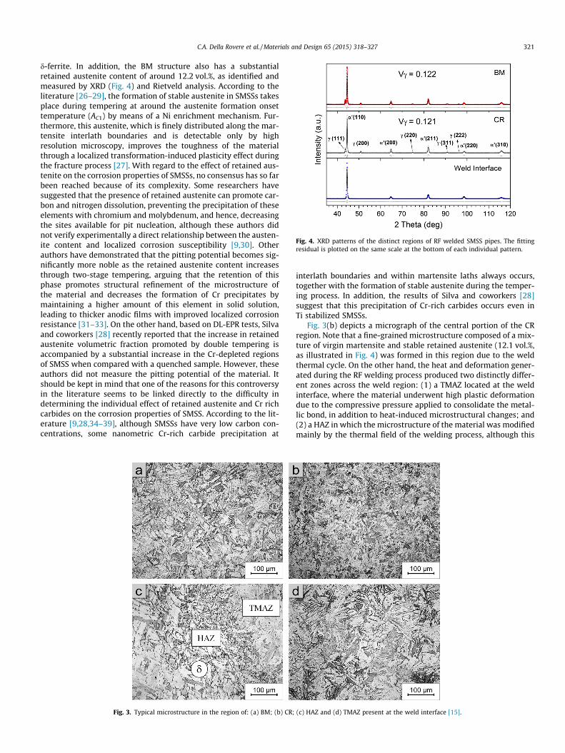
Fig. 4. XRD patterns of the distinct regions of RF welded SMSS pipes. The fittingresidual is plotted on the same scale at the bottom of each individual pattern.
C.A. Della Rovere et al. / Materials and Design 65 (2015) 318–327 321
d-ferrite. In addition, the BM structure also has a substantialretained austenite content of around 12.2 vol.%, as identified andmeasured by XRD (Fig. 4) and Rietveld analysis. According to theliterature [26–29], the formation of stable austenite in SMSSs takesplace during tempering at around the austenite formation onsettemperature (AC1) by means of a Ni enrichment mechanism. Fur-thermore, this austenite, which is finely distributed along the mar-tensite interlath boundaries and is detectable only by highresolution microscopy, improves the toughness of the materialthrough a localized transformation-induced plasticity effect duringthe fracture process [27]. With regard to the effect of retained aus-tenite on the corrosion properties of SMSSs, no consensus has so farbeen reached because of its complexity. Some researchers havesuggested that the presence of retained austenite can promote car-bon and nitrogen dissolution, preventing the precipitation of theseelements with chromium and molybdenum, and hence, decreasingthe sites available for pit nucleation, although these authors didnot verify experimentally a direct relationship between the austen-ite content and localized corrosion susceptibility [9,30]. Otherauthors have demonstrated that the pitting potential becomes sig-nificantly more noble as the retained austenite content increasesthrough two-stage tempering, arguing that the retention of thisphase promotes structural refinement of the microstructure ofthe material and decreases the formation of Cr precipitates bymaintaining a higher amount of this element in solid solution,leading to thicker anodic films with improved localized corrosionresistance [31–33]. On the other hand, based on DL-EPR tests, Silvaand coworkers [28] recently reported that the increase in retainedaustenite volumetric fraction promoted by double tempering isaccompanied by a substantial increase in the Cr-depleted regionsof SMSS when compared with a quenched sample. However, theseauthors did not measure the pitting potential of the material. Itshould be kept in mind that one of the reasons for this controversyin the literature seems to be linked directly to the difficulty indetermining the individual effect of retained austenite and Cr richcarbides on the corrosion properties of SMSS. According to the lit-erature [9,28,34–39], although SMSSs have very low carbon con-centrations, some nanometric Cr-rich carbide precipitation at
Fig. 3. Typical microstructure in the region of: (a) BM; (b) CR;
interlath boundaries and within martensite laths always occurs,together with the formation of stable austenite during the temper-ing process. In addition, the results of Silva and coworkers [28]suggest that this precipitation of Cr-rich carbides occurs even inTi stabilized SMSSs.
Fig. 3(b) depicts a micrograph of the central portion of the CRregion. Note that a fine-grained microstructure composed of a mix-ture of virgin martensite and stable retained austenite (12.1 vol.%,as illustrated in Fig. 4) was formed in this region due to the weldthermal cycle. On the other hand, the heat and deformation gener-ated during the RF welding process produced two distinctly differ-ent zones across the weld region: (1) a TMAZ located at the weldinterface, where the material underwent high plastic deformationdue to the compressive pressure applied to consolidate the metal-lic bond, in addition to heat-induced microstructural changes; and(2) a HAZ in which the microstructure of the material was modifiedmainly by the thermal field of the welding process, although this
(c) HAZ and (d) TMAZ present at the weld interface [15].
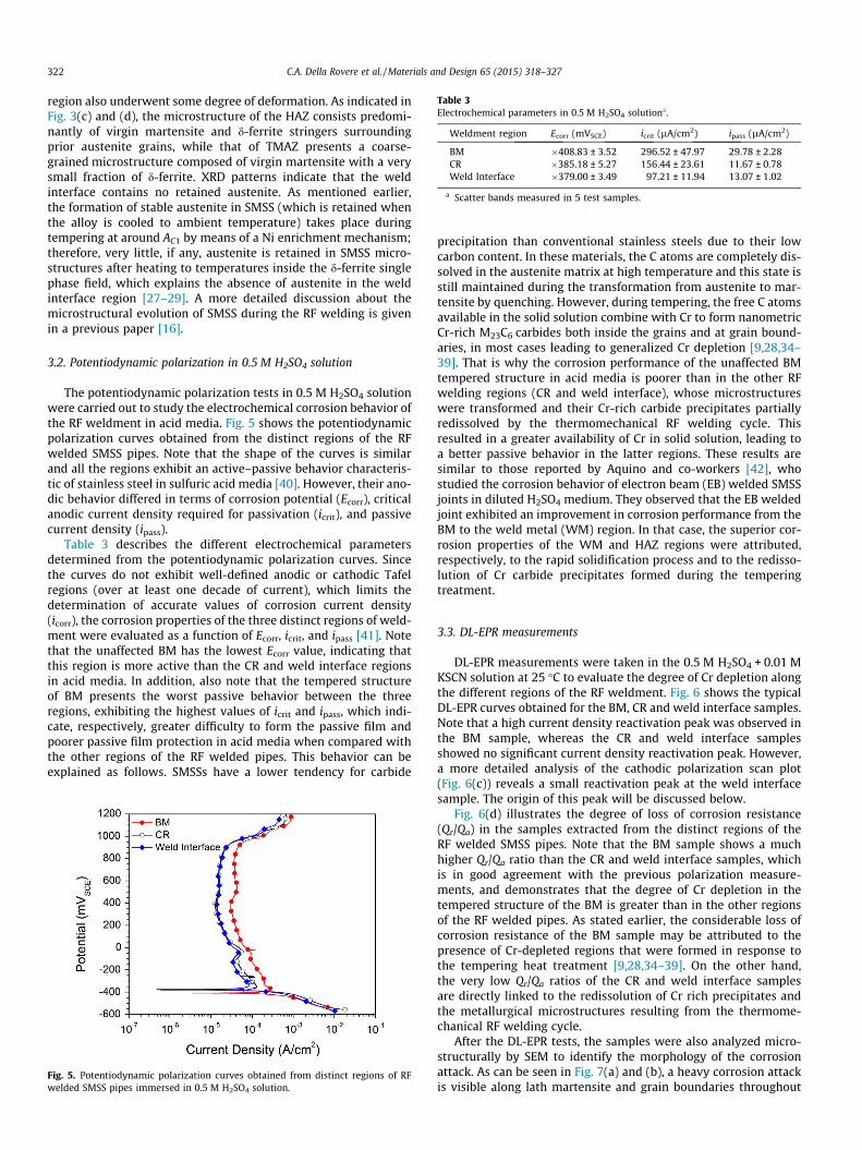
Table 3Electrochemical parameters in 0.5 M H2SO4 solutiona.
Weldment region Ecorr (mVSCE) icrit (lA/cm2) ipass (lA/cm2)
BM �408.83 ± 3.52 296.52 ± 47.97 29.78 ± 2.28CR �385.18 ± 5.27 156.44 ± 23.61 11.67 ± 0.78Weld Interface �379.00 ± 3.49 97.21 ± 11.94 13.07 ± 1.02
a Scatter bands measured in 5 test samples.
322 C.A. Della Rovere et al. / Materials and Design 65 (2015) 318–327
region also underwent some degree of deformation. As indicated inFig. 3(c) and (d), the microstructure of the HAZ consists predomi-nantly of virgin martensite and d-ferrite stringers surroundingprior austenite grains, while that of TMAZ presents a coarse-grained microstructure composed of virgin martensite with a verysmall fraction of d-ferrite. XRD patterns indicate that the weldinterface contains no retained austenite. As mentioned earlier,the formation of stable austenite in SMSS (which is retained whenthe alloy is cooled to ambient temperature) takes place duringtempering at around AC1 by means of a Ni enrichment mechanism;therefore, very little, if any, austenite is retained in SMSS micro-structures after heating to temperatures inside the d-ferrite singlephase field, which explains the absence of austenite in the weldinterface region [27–29]. A more detailed discussion about themicrostructural evolution of SMSS during the RF welding is givenin a previous paper [16].
3.2. Potentiodynamic polarization in 0.5 M H2SO4 solution
The potentiodynamic polarization tests in 0.5 M H2SO4 solutionwere carried out to study the electrochemical corrosion behavior ofthe RF weldment in acid media. Fig. 5 shows the potentiodynamicpolarization curves obtained from the distinct regions of the RFwelded SMSS pipes. Note that the shape of the curves is similarand all the regions exhibit an active–passive behavior characteris-tic of stainless steel in sulfuric acid media [40]. However, their ano-dic behavior differed in terms of corrosion potential (Ecorr), criticalanodic current density required for passivation (icrit), and passivecurrent density (ipass).
Table 3 describes the different electrochemical parametersdetermined from the potentiodynamic polarization curves. Sincethe curves do not exhibit well-defined anodic or cathodic Tafelregions (over at least one decade of current), which limits thedetermination of accurate values of corrosion current density(icorr), the corrosion properties of the three distinct regions of weld-ment were evaluated as a function of Ecorr, icrit, and ipass [41]. Notethat the unaffected BM has the lowest Ecorr value, indicating thatthis region is more active than the CR and weld interface regionsin acid media. In addition, also note that the tempered structureof BM presents the worst passive behavior between the threeregions, exhibiting the highest values of icrit and ipass, which indi-cate, respectively, greater difficulty to form the passive film andpoorer passive film protection in acid media when compared withthe other regions of the RF welded pipes. This behavior can beexplained as follows. SMSSs have a lower tendency for carbide
Fig. 5. Potentiodynamic polarization curves obtained from distinct regions of RFwelded SMSS pipes immersed in 0.5 M H2SO4 solution.
precipitation than conventional stainless steels due to their lowcarbon content. In these materials, the C atoms are completely dis-solved in the austenite matrix at high temperature and this state isstill maintained during the transformation from austenite to mar-tensite by quenching. However, during tempering, the free C atomsavailable in the solid solution combine with Cr to form nanometricCr-rich M23C6 carbides both inside the grains and at grain bound-aries, in most cases leading to generalized Cr depletion [9,28,34–39]. That is why the corrosion performance of the unaffected BMtempered structure in acid media is poorer than in the other RFwelding regions (CR and weld interface), whose microstructureswere transformed and their Cr-rich carbide precipitates partiallyredissolved by the thermomechanical RF welding cycle. Thisresulted in a greater availability of Cr in solid solution, leading toa better passive behavior in the latter regions. These results aresimilar to those reported by Aquino and co-workers [42], whostudied the corrosion behavior of electron beam (EB) welded SMSSjoints in diluted H2SO4 medium. They observed that the EB weldedjoint exhibited an improvement in corrosion performance from theBM to the weld metal (WM) region. In that case, the superior cor-rosion properties of the WM and HAZ regions were attributed,respectively, to the rapid solidification process and to the redisso-lution of Cr carbide precipitates formed during the temperingtreatment.
3.3. DL-EPR measurements
DL-EPR measurements were taken in the 0.5 M H2SO4 + 0.01 MKSCN solution at 25 �C to evaluate the degree of Cr depletion alongthe different regions of the RF weldment. Fig. 6 shows the typicalDL-EPR curves obtained for the BM, CR and weld interface samples.Note that a high current density reactivation peak was observed inthe BM sample, whereas the CR and weld interface samplesshowed no significant current density reactivation peak. However,a more detailed analysis of the cathodic polarization scan plot(Fig. 6(c)) reveals a small reactivation peak at the weld interfacesample. The origin of this peak will be discussed below.
Fig. 6(d) illustrates the degree of loss of corrosion resistance(Qr/Qa) in the samples extracted from the distinct regions of theRF welded SMSS pipes. Note that the BM sample shows a muchhigher Qr/Qa ratio than the CR and weld interface samples, whichis in good agreement with the previous polarization measure-ments, and demonstrates that the degree of Cr depletion in thetempered structure of the BM is greater than in the other regionsof the RF welded pipes. As stated earlier, the considerable loss ofcorrosion resistance of the BM sample may be attributed to thepresence of Cr-depleted regions that were formed in response tothe tempering heat treatment [9,28,34–39]. On the other hand,the very low Qr/Qa ratios of the CR and weld interface samplesare directly linked to the redissolution of Cr rich precipitates andthe metallurgical microstructures resulting from the thermome-chanical RF welding cycle.
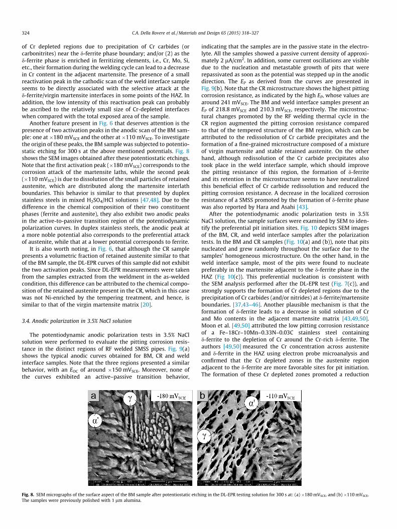
After the DL-EPR tests, the samples were also analyzed micro-structurally by SEM to identify the morphology of the corrosionattack. As can be seen in Fig. 7(a) and (b), a heavy corrosion attackis visible along lath martensite and grain boundaries throughout
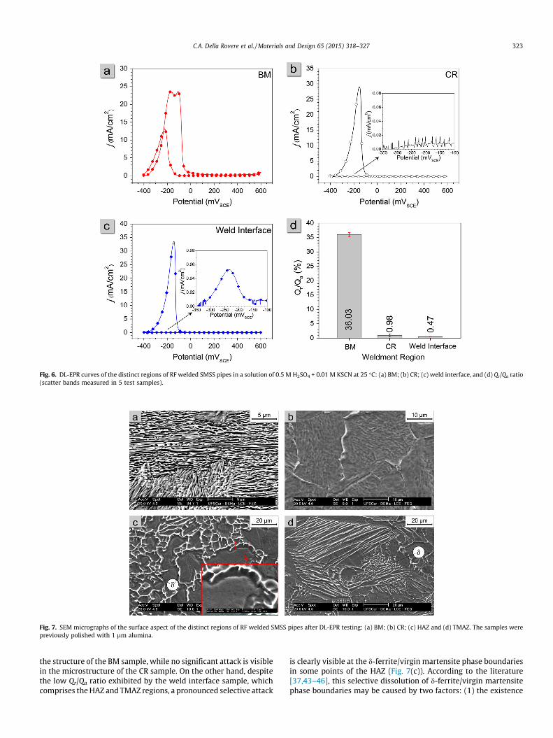
Fig. 6. DL-EPR curves of the distinct regions of RF welded SMSS pipes in a solution of 0.5 M H2SO4 + 0.01 M KSCN at 25 �C: (a) BM; (b) CR; (c) weld interface, and (d) Qr/Qa ratio(scatter bands measured in 5 test samples).
Fig. 7. SEM micrographs of the surface aspect of the distinct regions of RF welded SMSS pipes after DL-EPR testing: (a) BM; (b) CR; (c) HAZ and (d) TMAZ. The samples werepreviously polished with 1 lm alumina.
C.A. Della Rovere et al. / Materials and Design 65 (2015) 318–327 323
the structure of the BM sample, while no significant attack is visiblein the microstructure of the CR sample. On the other hand, despitethe low Qr/Qa ratio exhibited by the weld interface sample, whichcomprises the HAZ and TMAZ regions, a pronounced selective attack
is clearly visible at the d-ferrite/virgin martensite phase boundariesin some points of the HAZ (Fig. 7(c)). According to the literature[37,43–46], this selective dissolution of d-ferrite/virgin martensitephase boundaries may be caused by two factors: (1) the existence
324 C.A. Della Rovere et al. / Materials and Design 65 (2015) 318–327
of Cr depleted regions due to precipitation of Cr carbides (orcarbonitrites) near the d-ferrite phase boundary; and/or (2) as thed-ferrite phase is enriched in ferritizing elements, i.e., Cr, Mo, Si,etc., their formation during the welding cycle can lead to a decreasein Cr content in the adjacent martensite. The presence of a smallreactivation peak in the cathodic scan of the weld interface sampleseems to be directly associated with the selective attack at thed-ferrite/virgin martensite interfaces in some points of the HAZ. Inaddition, the low intensity of this reactivation peak can probablybe ascribed to the relatively small size of Cr-depleted interfaceswhen compared with the total exposed area of the sample.
Another feature present in Fig. 6 that deserves attention is thepresence of two activation peaks in the anodic scan of the BM sam-ple: one at�180 mVSCE and the other at�110 mVSCE. To investigatethe origin of these peaks, the BM sample was subjected to potentio-static etching for 300 s at the above mentioned potentials. Fig. 8shows the SEM images obtained after these potentiostatic etchings.Note that the first activation peak (�180 mVSCE) corresponds to thecorrosion attack of the martensite laths, while the second peak(�110 mVSCE) is due to dissolution of the small particles of retainedaustenite, which are distributed along the martensite interlathboundaries. This behavior is similar to that presented by duplexstainless steels in mixed H2SO4/HCl solutions [47,48]. Due to thedifference in the chemical composition of their two constituentphases (ferrite and austenite), they also exhibit two anodic peaksin the active-to-passive transition region of the potentiodynamicpolarization curves. In duplex stainless steels, the anodic peak ata more noble potential also corresponds to the preferential attackof austenite, while that at a lower potential corresponds to ferrite.
It is also worth noting, in Fig. 6, that although the CR samplepresents a volumetric fraction of retained austenite similar to thatof the BM sample, the DL-EPR curves of this sample did not exhibitthe two activation peaks. Since DL-EPR measurements were takenfrom the samples extracted from the weldment in the as-weldedcondition, this difference can be attributed to the chemical compo-sition of the retained austenite present in the CR, which in this casewas not Ni-enriched by the tempering treatment, and hence, issimilar to that of the virgin martensite matrix [20].
3.4. Anodic polarization in 3.5% NaCl solution
The potentiodynamic anodic polarization tests in 3.5% NaClsolution were performed to evaluate the pitting corrosion resis-tance in the distinct regions of RF welded SMSS pipes. Fig. 9(a)shows the typical anodic curves obtained for BM, CR and weldinterface samples. Note that the three regions presented a similarbehavior, with an EOC of around �150 mVSCE. Moreover, none ofthe curves exhibited an active–passive transition behavior,
Fig. 8. SEM micrographs of the surface aspect of the BM sample after potentiostatic etchThe samples were previously polished with 1 lm alumina.
indicating that the samples are in the passive state in the electro-lyte. All the samples showed a passive current density of approxi-mately 2 lA/cm2. In addition, some current oscillations are visibledue to the nucleation and metastable growth of pits that wererepassivated as soon as the potential was stepped up in the anodicdirection. The EP as derived from the curves are presented inFig. 9(b). Note that the CR microstructure shows the highest pittingcorrosion resistance, as indicated by the high EP, whose values arearound 241 mVSCE. The BM and weld interface samples present anEP of 218.8 mVSCE and 210.3 mVSCE, respectively. The microstruc-tural changes promoted by the RF welding thermal cycle in theCR region augmented the pitting corrosion resistance comparedto that of the tempered structure of the BM region, which can beattributed to the redissolution of Cr carbide precipitates and theformation of a fine-grained microstructure composed of a mixtureof virgin martensite and stable retained austenite. On the otherhand, although redissolution of the Cr carbide precipitates alsotook place in the weld interface sample, which should improvethe pitting resistance of this region, the formation of d-ferriteand its retention in the microstructure seems to have neutralizedthis beneficial effect of Cr carbide redissolution and reduced thepitting corrosion resistance. A decrease in the localized corrosionresistance of a SMSS promoted by the formation of d-ferrite phasewas also reported by Hara and Asahi [43].
After the potentiodynamic anodic polarization tests in 3.5%NaCl solution, the sample surfaces were examined by SEM to iden-tify the preferential pit initiation sites. Fig. 10 depicts SEM imagesof the BM, CR, and weld interface samples after the polarizationtests. In the BM and CR samples (Fig. 10(a) and (b)), note that pitsnucleated and grew randomly throughout the surface due to thesamples’ homogeneous microstructure. On the other hand, in theweld interface sample, most of the pits were found to nucleatepreferably in the martensite adjacent to the d-ferrite phase in theHAZ (Fig 10(c)). This preferential nucleation is consistent withthe SEM analysis performed after the DL-EPR test (Fig. 7(c)), andstrongly supports the formation of Cr depleted regions due to theprecipitation of Cr carbides (and/or nitrides) at d-ferrite/martensiteboundaries. [37,43–46]. Another plausible mechanism is that theformation of d-ferrite leads to a decrease in solid solution of Crand Mo contents in the adjacent martensite matrix [43,49,50].Moon et al. [49,50] attributed the low pitting corrosion resistanceof a Fe–18Cr–10Mn–0.33N–0.03C stainless steel containingd-ferrite to the depletion of Cr around the Cr-rich d-ferrite. Theauthors [49,50] measured the Cr concentration across austeniteand d-ferrite in the HAZ using electron probe microanalysis andconfirmed that the Cr depleted zones in the austenite regionadjacent to the d-ferrite are more favorable sites for pit initiation.The formation of these Cr depleted zones promoted a reduction
ing in the DL-EPR testing solution for 300 s at: (a) �180 mVSCE, and (b) �110 mVSCE.
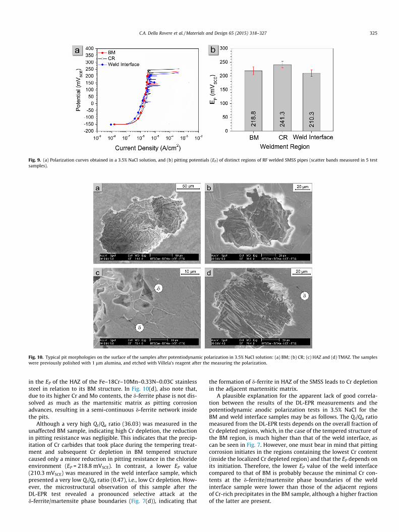
Fig. 9. (a) Polarization curves obtained in a 3.5% NaCl solution, and (b) pitting potentials (EP) of distinct regions of RF welded SMSS pipes (scatter bands measured in 5 testsamples).
Fig. 10. Typical pit morphologies on the surface of the samples after potentiodynamic polarization in 3.5% NaCl solution: (a) BM; (b) CR; (c) HAZ and (d) TMAZ. The sampleswere previously polished with 1 lm alumina, and etched with Villela’s reagent after the measuring the polarization.
C.A. Della Rovere et al. / Materials and Design 65 (2015) 318–327 325
in the EP of the HAZ of the Fe–18Cr–10Mn–0.33N–0.03C stainlesssteel in relation to its BM structure. In Fig. 10(d), also note that,due to its higher Cr and Mo contents, the d-ferrite phase is not dis-solved as much as the martensitic matrix as pitting corrosionadvances, resulting in a semi-continuous d-ferrite network insidethe pits.
Although a very high Qr/Qa ratio (36.03) was measured in theunaffected BM sample, indicating high Cr depletion, the reductionin pitting resistance was negligible. This indicates that the precip-itation of Cr carbides that took place during the tempering treat-ment and subsequent Cr depletion in BM tempered structurecaused only a minor reduction in pitting resistance in the chlorideenvironment (EP = 218.8 mVSCE). In contrast, a lower EP value(210.3 mVSCE) was measured in the weld interface sample, whichpresented a very low Qr/Qa ratio (0.47), i.e., low Cr depletion. How-ever, the microstructural observation of this sample after theDL-EPR test revealed a pronounced selective attack at thed-ferrite/martensite phase boundaries (Fig. 7(d)), indicating that
the formation of d-ferrite in HAZ of the SMSS leads to Cr depletionin the adjacent martensitic matrix.
A plausible explanation for the apparent lack of good correla-tion between the results of the DL-EPR measurements and thepotentiodynamic anodic polarization tests in 3.5% NaCl for theBM and weld interface samples may be as follows. The Qr/Qa ratiomeasured from the DL-EPR tests depends on the overall fraction ofCr depleted regions, which, in the case of the tempered structure ofthe BM region, is much higher than that of the weld interface, ascan be seen in Fig. 7. However, one must bear in mind that pittingcorrosion initiates in the regions containing the lowest Cr content(inside the localized Cr depleted region) and that the EP depends onits initiation. Therefore, the lower EP value of the weld interfacecompared to that of BM is probably because the minimal Cr con-tents at the d-ferrite/martensite phase boundaries of the weldinterface sample were lower than those of the adjacent regionsof Cr-rich precipitates in the BM sample, although a higher fractionof the latter are present.
326 C.A. Della Rovere et al. / Materials and Design 65 (2015) 318–327
Owing to the precipitation of other Cr-rich phases in addition to Crcarbides in the structure of a type 347 austenitic stainless steel, Chan-dra et al. [51] also recently reported a certain discrepancy betweenDL-EPR measurements and pitting corrosion behavior. These authorsobserved that, in addition to Cr depletion, the presence of phaseboundaries due to possible heterogeneities in the microstructure alsoplays a significant role in pit initiation in stainless steels.
As a final comment, this study clearly revealed that DL-EPRmeasurements should be used with caution to avoid misinterpre-tation, and particularly in the case of SMSSs, which are used inthe quenched and tempered condition, one should not expect thatthis technique will readily pinpoint Cr depleted regions onlythrough the relative charges (or peak heights) of the anodic andcathodic polarization scan, because the size of the Cr impoverishedregion in HAZ is usually very small and cannot be distinguishedaccurately using a relatively large exposed area. In this case, amicroscopic examination of the corrosion attack and of the charac-teristics of etched phases after DL-EPR measurements, in additionto other electrochemical tests, are required. Furthermore, it shouldbe noted that for the oil industry to adopt RF welding of SMSSs,particularly for onshore and offshore pipeline applications, addi-tional tests should be performed, in view of the susceptibility ofRF weldments to stress corrosion cracking and hydrogen embrittle-ment. In future works, the authors will try to move forward onthese measures, systematically studying the effect of different heattreatments before and after the RF welding process on the globalbehavior of the welded joint.
4. Conclusions
The microstructures and corrosion properties of RF weldedSMSS pipes were studied based on OM, SEM, XRD analyses, poten-tiodynamic polarization and DL-EPR measurements. Based on thechanges in the microstructure promoted by the RF welding processand the resulting electrochemical properties, the following conclu-sions can be drawn:
(1) Due to the redissolution of Cr carbide precipitates promotedby the RF welding thermal cycle, the RF weldment regionsexhibit better corrosion performance in acid media thanthe tempered structure of the unaffected BM.
(2) The generalized precipitation of Cr carbides at both lathmartensite and grain boundaries in the tempered structureof the unaffected BM induced considerable Cr depletion(Qr/Qa ratio), as indicated by DL-EPR test measurements.However, no significant Cr depletion was detected in theDL-EPR measurement of the weld interface region contain-ing d-ferrite, although pronounced dissolution was observedat the d-ferrite/martensite phase boundaries after the test.
(3) A decrease in pitting corrosion resistance was observed dueto d-ferrite formation at the weld interface, indicated by adecrease in the EP during anodic polarization in 3.5% NaClsolution. In contrast, Cr carbide precipitation in the BMstructure promoted by the tempering treatment did not sig-nificantly diminish the pitting corrosion resistance.
(4) The microstructural changes promoted by the RF weldingthermal cycle in the CR region led to an increase in pittingcorrosion resistance in 3.5% NaCl solution compared to thatof the unaffected BM region.
Acknowledgments
The authors gratefully acknowledge FAPESP (São PauloResearch Foundation – Grant No. 12/16113-6), PPGCEM/UFSCar
(Postgraduate Program in Materials Science and Engineering ofthe Federal University of São Carlos) and the Brazilian ResearchFunding Agency CNPq (National Council for Scientific and Techno-logical Development) for their financial support of this work.
References
[1] van der Winden H, Toussaint P, Coudreuse L. Past, present and future ofweldable supermartensitic alloys. In: Proceedings of the supermartensiticstainless steels 2002. Brussels, Belgium; 2002. p. 9–13 [paper P001].
[2] Smith L, Celant M. Martensitic stainless steels in context. In: Proceedings of thesupermartensitic stainless steels 2002. Brussels, Belgium; 2002. p. 14–20[paper P017].
[3] Anselmo N, May JE, Mariano NA, Nascente PAP, Kuri SE. Corrosion behavior ofsupermartensitic stainless steel in aerated and CO2-saturated syntheticseawater. Mater Sci Eng A 2006;428:73–9.
[4] Kondo K, Ueda M, Ogawa K, Amaya H, Hirata H, Takabe H, Miyazaki Y. Alloydesign of super 13 Cr martensitic stainless steel (development of super 13 Crmartensitic stainless steel for line pipe - 1). In: Proceedings of thesupermartensitic stainless steels ’99. Brussels, Belgium; 1999. p. 11–18[paper S99–1].
[5] Rodrigues CAD, Lorenzo PLD, Sokolowski A, Barbosa CA, Rollo JMDA. Titaniumand molybdenum content in supermartensitic stainless steel. Mater Sci Eng A2007;460–461:149–52.
[6] Ma XP, Liu CM, Wang LJ, Subramanian SV. Role of Nb in low interstitial 13Crsuper martensitic stainless steel. Mater Sci Eng A 2011;528:6812–8.
[7] Omura T, Kushida T, Hayashi T, Matsuhiro Y, Komizo Y. Super 13Cr martensiticstainless steel line pipe by super laser welding. In: Proceedings of thesupermartensitic stainless steels ’99. Brussels, Belgium; 1999. p. 127–133[paper S99–15].
[8] Aquino JM, Della Rovere CA, Kuri SE. Intergranular corrosion susceptibility insupermartensitic stainless steel weldments. Corros Sci 2009;51:2316–23.
[9] Aquino JM, Della Rovere CA, Kuri SE. Localized corrosion susceptibility ofsupermartensitic stainless steel in welded joints. Corrosion 2008;64:35–9.
[10] Bala Srinivasan P, Sharkawy SW, Dietzel W. Hydrogen assisted stress-crackingbehaviour of electron beam welded supermartensitic stainless steelweldments. Mater Sci Eng A 2004;385:6–12.
[11] Nicholas ED. Radial friction welding. Weld J 1983;62:17–29.[12] Dunkerton SB, Johansen A, Frich S. Radial friction welding for offshore
pipelines. Weld J 1987;66:40–7.[13] Torster F, Santos JF, Hutt G, Koçak M. Metallurgical and mechanical properties
of radial friction welded Ti–6Al–4V–0.1Ru risers. In: Proceedings of the 17thinternational conference on offshore mechanics and arctic engineering. Lisbon,Portugal; 1998. p. 1–6 [paper OAME98–2208].
[14] Luo J, Xiang J, Liu D, Li F, Xue k. Radial friction welding interface between brassand high carbon steel. J Mater Process Technol 2012;212:385–92.
[15] Della Rovere CA, Ribeiro CR, Silva R, Alcântara NG, Kuri SE. Local mechanicalproperties of radial friction welded supermartensitic stainless steel pipes.Mater Des 2014;56:423–7.
[16] Della Rovere CA, Ribeiro CR, Silva R, Baroni LFS, Alcântara NG, Kuri SE.Microstructural and mechanical characterization of radial friction weldedsupermartensitic stainless steel joints. Mater Sci Eng A 2013;586:86–92.
[17] Lutterotti L, Chateigner D, Ferrari S, Ricote J. Texture, residual stress andstructural analysis of thin films using a combined X-ray analysis. Thin SolidFilms 2004;450:34–41.
[18] Pereda MD, Gervasi CA, Llorente CL, Bilmes PD. Microelectrochemicalcorrosion study of super martensitic welds in chloride-containing media.Corros Sci 2011;53:3934–41.
[19] Cıhal V, Stefec R. On the development of the electrochemical potentiokineticmethod. Electrochim Acta 2001;46:3867–77.
[20] Cıhal V, Blahetová M, Hubácková J, Krhutová Z, Lasek S, Mazanec K. Corrosionand structural testing of martensitic steels by electrochemical polarizationmethod. In: Proceedings of the supermartensitic stainless steels 2002.Brussels, Belgium; 2002. p. 83–88 [paper P011].
[21] Akashi M, Kawamoto T, Umemura F, Gijutsu B. Evaluation of IGSCCsusceptibility of austenitic stainless steels using electrochemical reactivationmethod. Corros Eng 1980;29:163–9.
[22] Falleiros NA, Magri M, Falleiros IGS. Intergranular corrosion in a martensiticstainless steel detected by electrochemical test. Corrosion 1999;55:169–769.
[23] Della Rovere CA, Santos FS, Silva R, Souza CAC, Kuri SE. Influence of long-termlow-temperature aging on the microhardness and corrosion properties ofduplex stainless steel. Corros Sci 2013;68:84–90.
[24] Wu TF, Ping TP, Tsai WT. Effect of electrolyte composition on theelectrochemical potentiokinetic reactivation behavior of alloy 600. J NuclMater 2001;295:233–43.
[25] Assis KS, Sousa FVV, Miranda M, Mattos ICPM, Vivier V, Mattos OR. Assessmentof electrochemical methods used on corrosion of superduplex stainless steel.Corros Sci 2012;59:71–80.
[26] Gesnouin C, Hazarabedian A, Bruzzoni P, Ovejero-García J, Bilmes P, Llorente C.Effect of post-weld heat treatment on the microstructure and hydrogenpermeation of 13CrNiMo steels. Corros Sci 2004;46:1633–47.
[27] Bilmes PD, Solari M, Llorente CL. Characteristics and effects of austeniteresulting from tempering of 13Cr–NiMo martensitic steel weld metals. MaterCharact 2001;46:285–96.
C.A. Della Rovere et al. / Materials and Design 65 (2015) 318–327 327
[28] da Silva GF, Tavares SSM, Pardal JM, Silva MR, de Abreu HFG. Influence of heattreatments on toughness and sensitization of a Ti-alloyed supermartensiticstainless steel. J Mater Sci 2011;46:7737–44.
[29] Thibault D, Bocher P, Thomas M, Lanteigne J, Hovington P, Robichaud P.Reformed austenite transformation during fatigue crack propagation of13%Cr–4%Ni stainless steel. Mater Sci Eng A 2011;528:6519–26.
[30] Kimura M, Miyata Y, Toyooka T, Kitahaba Y. Effect of retained austenite oncorrosion performance for modified 13% Cr steel pipe. Corrosion2001;57:433–9.
[31] Bilmes PD, Llorente CL, Saire Huamán L, Gassa LM, Gervasi CA. Microstructureand pitting corrosion of 13CrNiMo weld metals. Corros Sci 2006;48:3261–70.
[32] Bilmes PD, Llorente CL, Méndez CM, Gervasi CA. Microstructure, heattreatment and pitting corrosion of 13CrNiMo plate and weld metals. CorrosSci 2009;51:876–81.
[33] Gervasi CA, Méndez CM, Bilmes PD, Llorente CL. Analysis of the impact of alloymicrostructural properties on passive films formed on low-C 13CrNiMomartensitic stainless steels. Mater Chem Phys 2011;126:178–82.
[34] Camillo APC, Della Rovere CA, Aquino JM, Kuri SE. Efeito do revenido naresistência à corrosão dos aços inoxidáveis supermartensíticos. REM RevistaEscola de Minas 2010;63:117–22.
[35] Vodared V, Tvrdy M, Korcak A. Heat treatment of supermartensitic steels. InzMater 2001;5:939–41.
[36] Truman JE. Corrosion resistance of 13% chromium steels as influenced bytempering treatments. Br Corros J 1976;11:92–6.
[37] Folkhard E. Welding metallurgy of stainless steel. 1st ed. New York: Springer-Verlag; 1988.
[38] Ma X, Wang L, Subramanian SV, Liu C. Studies on Nb microalloying of 13Crsuper martensitic stainless steel. Metall Mater Trans A 2012;43:4475–86.
[39] Pickering FB. The metallurgical evolution of stainless steels. 1sted. London: American Society for Metals; 1979.
[40] Sedriks AJ. Corrosion of stainless steel. 2nd ed. New York: Wiley; 1996.[41] McCafferty E. Validation of corrosion rates measured by the Tafel
extrapolation method. Corros Sci 2005;47:3202–15.[42] Aquino JM, Della Rovere CA, Kuri SE. Anodic behaviour of supermartensitic
stainless steel weldments. Corros Eng Sci Technol 2010;45:150–4.[43] Hara T, Asahi H. Effect of d-ferrite on sulfide stress cracking in a low carbon 13
mass% chromium steel. ISIJ Int 2000;40:1134–41.[44] Smith L. Phorgotten phenomena: sensitization of martensitic stainless steels.
Mater Perform 2002;41:54–5.[45] Ladanova E, Solberg JK, Rogne T. Carbide precipitation in HAZ of multipass
welds in titanium containing and titanium free supermartensitic stainlesssteels Part 1 – proposed precipitation mechanisms. Corros Eng Sci Technol2006;41:143–51.
[46] Turnbull A, Nimmo B. Stress corrosion testing of welded supermartensiticstainless steels for oil and gas pipelines. Corros Eng Sci Technol2005;40:103–9.
[47] Lo I-H, Fu Y, Lin C-J, Tsai W-T. Effect of electrolyte composition on the active-to-passive transition behavior of 2205 duplex stainless steel in H2SO4/HClsolutions. Corros Sci 2006;48:696–708.
[48] Tsai W-T, Chen J-R. Galvanic corrosion between the constituent phases induplex stainless steel. Corros Sci 2007;49:3659–68.
[49] Moon J, Ha H-Y, Lee T-H, Lee C. Different aspect of pitting corrosion andinterphase corrosion in the weld heat-affected zone of high-nitrogen Fe–18Cr–10Mn–N steel. Mater Chem Phys 2013;142:556–63.
[50] Moon J, Ha H-Y, Lee T-H, Lee C. Corrosion behavior in high heat input weldedheat-affected zone of Ni-free high-nitrogen Fe–18Cr–10Mn–N austeniticstainless steel. Mater Charact 2013;82:113–9.
[51] Chandra K, Kain V, Tewari R. Microstructural and electrochemicalcharacterisation of heat-treated 347 stainless steel with different phases.Corros Sci 2013;67:118–29.