corcom product guide - mt-system...4 filter part numbering system corcom product guide catalog...
TRANSCRIPT

CORCOM Product Guide

CORCOM Product Guide
DisclaimerWhile Tyco Electronics has made every reasonable effort to ensure the accuracy of theinformation in this catalog, Tyco Electronicsdoes not guarantee that it is error-free, nor does Tyco Electronics make any other representation, warranty, or guarantee that the information isaccurate, correct, reliable or current. TycoElectronics reserves the right to make anyadjustments to the information contained herein at any time without notice. TycoElectronic expressly disclaims all implied warranties regarding the information containedherein, including but not limited to any implied warranties of merchantability or fitness for aparticular purpose.
It is recommended that you test any new orreplacement product before incorporating into a system.
The dimensions in this catalog are for reference purposes only and are subject tochange without notice. Dimensions are in inches over [millimeters], unless otherwisespecified. Always consult our customer drawings for recommended PC board layoutand panel cutout dimensions; do not use catalog dimensions. Specifications are subject to change without notice. Consult TycoElectronics for the latest dimensions and designspecifications.
RFI Power Line FiltersTyco Electronics offers over 300 solutions for RFI problems associated with susceptibility, as well as compliance with international emissions standards.
Signal Line ProductsCORCOM's SIGNAL SENTRYFiltered Modular Jack connectorseries combines different levels of filtering with RJ45 and RJ11 modular jacks as well as surfacemountable filters to address signalline noise problems and crosstalk.
DC FiltersTyco Electronics has provided solutions in both power line filtering and signal line filtering applications for many leading communications companies. As data transmission speeds increaseand EMI-RFI issues multiply, Tyco Electronics has developed products to address the newer challenges communications companies encounter.
Power Entry ModulesA complete line of power entry modules solves a variety of powerentry needs by combining functions to reduce cost, space and labor.
Tyco Electronics CORCOM Products
World HeadquartersUSAPhone: 847-680-7400Fax: 847-680-8169
West Coast6700 Fallbrook Ave., Suite 287West Hills, CA 91307 USAPhone: 818-226-4306Fax: 818-704-1757
Germany GmbHFinsinger Feld 1D-85521 Ottobrunn,GermanyPhone: 49-89-6089-0Fax: 49-89-6089-767
© Copyright 2003, 2004 and 2006 by Tyco Electronics Corporation. All Rights Reserved.CHAMELEON, CORCOM, FASTON, SIGNAL SENTRY and TYCO are trademarks.Other products, logos, and Company names mentioned herein may be trademarks of their respective owners.

CORCOM Product Guide
Main Table of Contents
Navigating the Catalog . . . . . . . . . . . . . . . . . . . . . . . . . . . . . . . . . . . . . . . . . . . . . . . . . . . .3Filter Part Numbering System . . . . . . . . . . . . . . . . . . . . . . . . . . . . . . . . . . . . . . . . . . . . . . . .4RFI Power Line Filters . . . . . . . . . . . . . . . . . . . . . . . . . . . . . . . . . . . . . . . . . . . . . . . . .5-104
Table of Contents . . . . . . . . . . . . . . . . . . . . . . . . . . . . . . . . . . . . . . . . . . . . . . . . . . . . . . . .5Selector Chart . . . . . . . . . . . . . . . . . . . . . . . . . . . . . . . . . . . . . . . . . . . . . . . . . . . . . . . . .6, 7A Series . . . . . . . . . . . . . . . . . . . . . . . . . . . . . . . . . . . . . . . . . . . . . . . . . . . . . . . . . . . . .8, 9Accessories . . . . . . . . . . . . . . . . . . . . . . . . . . . . . . . . . . . . . . . . . . . . . . . . . . . . . . .142,143ADT Series . . . . . . . . . . . . . . . . . . . . . . . . . . . . . . . . . . . . . . . . . . . . . . . . . . . . . . . . .10, 11AQ Series . . . . . . . . . . . . . . . . . . . . . . . . . . . . . . . . . . . . . . . . . . . . . . . . . . . . . . . . . .12, 13AYA Series . . . . . . . . . . . . . . . . . . . . . . . . . . . . . . . . . . . . . . . . . . . . . . . . . . . . . . . . .14, 15AYC Series . . . . . . . . . . . . . . . . . . . . . . . . . . . . . . . . . . . . . . . . . . . . . . . . . . . . . . . . .16, 17AYO Series . . . . . . . . . . . . . . . . . . . . . . . . . . . . . . . . . . . . . . . . . . . . . . . . . . . . . . . . .18, 19B Series . . . . . . . . . . . . . . . . . . . . . . . . . . . . . . . . . . . . . . . . . . . . . . . . . . . . . . . . . . .20, 21DK Series . . . . . . . . . . . . . . . . . . . . . . . . . . . . . . . . . . . . . . . . . . . . . . . . . . . . . . . . . .22, 23EAH Series . . . . . . . . . . . . . . . . . . . . . . . . . . . . . . . . . . . . . . . . . . . . . . . . . . . . . . . .24, 25EAS Series . . . . . . . . . . . . . . . . . . . . . . . . . . . . . . . . . . . . . . . . . . . . . . . . . . . . . . . . .26, 27EBF Series . . . . . . . . . . . . . . . . . . . . . . . . . . . . . . . . . . . . . . . . . . . . . . . . . . . . . . . . .28, 29EBH Series . . . . . . . . . . . . . . . . . . . . . . . . . . . . . . . . . . . . . . . . . . . . . . . . . . . . . . . . .24, 25EBS Series . . . . . . . . . . . . . . . . . . . . . . . . . . . . . . . . . . . . . . . . . . . . . . . . . . . . . . . . .26, 27EC Series . . . . . . . . . . . . . . . . . . . . . . . . . . . . . . . . . . . . . . . . . . . . . . . . . . . . . . . . . .30, 31ED Series . . . . . . . . . . . . . . . . . . . . . . . . . . . . . . . . . . . . . . . . . . . . . . . . . . . . . . . . . .32, 33EDP Series . . . . . . . . . . . . . . . . . . . . . . . . . . . . . . . . . . . . . . . . . . . . . . . . . . . . . . . . .34, 35EEA Series . . . . . . . . . . . . . . . . . . . . . . . . . . . . . . . . . . . . . . . . . . . . . . . . . . . . . . . . .36, 37EEB Series . . . . . . . . . . . . . . . . . . . . . . . . . . . . . . . . . . . . . . . . . . . . . . . . . . . . . . . . .36, 37EEJ Series . . . . . . . . . . . . . . . . . . . . . . . . . . . . . . . . . . . . . . . . . . . . . . . . . . .38, 39, 40, 41EF Series . . . . . . . . . . . . . . . . . . . . . . . . . . . . . . . . . . . . . . . . . . . . . . . . . . . . . . . . . .42, 43EJH Series . . . . . . . . . . . . . . . . . . . . . . . . . . . . . . . . . . . . . . . . . . . . . . . . . . .44, 45, 46, 47EJM Series . . . . . . . . . . . . . . . . . . . . . . . . . . . . . . . . . . . . . . . . . . . . . . . . . . . . . . . . .48, 49EJS Series . . . . . . . . . . . . . . . . . . . . . . . . . . . . . . . . . . . . . . . . . . . . . . . . . . . . . . . . .50, 51EJT Series . . . . . . . . . . . . . . . . . . . . . . . . . . . . . . . . . . . . . . . . . . . . . . . . . . . . . . . . .52, 53EMC Series . . . . . . . . . . . . . . . . . . . . . . . . . . . . . . . . . . . . . . . . . . . . . . . . . . . . . . . . .54, 55EOP Series . . . . . . . . . . . . . . . . . . . . . . . . . . . . . . . . . . . . . . . . . . . . . . . . . . . . . . . . .34, 35EP Series . . . . . . . . . . . . . . . . . . . . . . . . . . . . . . . . . . . . . . . . . . . . . . . . . . . . . . . . . .56, 57FC Series . . . . . . . . . . . . . . . . . . . . . . . . . . . . . . . . . . . . . . . . . . . . . . . . . . . . . . . . . .58, 59FCD Series . . . . . . . . . . . . . . . . . . . . . . . . . . . . . . . . . . . . . . . . . . . . . . . . . . . . . . . . .60, 61FL Series . . . . . . . . . . . . . . . . . . . . . . . . . . . . . . . . . . . . . . . . . . . . . . . . . . . . . . . . . . .62, 63G Series . . . . . . . . . . . . . . . . . . . . . . . . . . . . . . . . . . . . . . . . . . . . . . . . . . . . . . . . . . .64, 65H Series . . . . . . . . . . . . . . . . . . . . . . . . . . . . . . . . . . . . . . . . . . . . . . . . . . . . . . . . . . .66, 67HQ Series . . . . . . . . . . . . . . . . . . . . . . . . . . . . . . . . . . . . . . . . . . . . . . . . . . . . . . . . . .68, 69HT Series . . . . . . . . . . . . . . . . . . . . . . . . . . . . . . . . . . . . . . . . . . . . . . . . . . . . . . . . . .70, 71HZ Series . . . . . . . . . . . . . . . . . . . . . . . . . . . . . . . . . . . . . . . . . . . . . . . . . . . . . . . . . .72, 73K Series . . . . . . . . . . . . . . . . . . . . . . . . . . . . . . . . . . . . . . . . . . . . . . . . . . . . .74, 75, 76, 77MV Series . . . . . . . . . . . . . . . . . . . . . . . . . . . . . . . . . . . . . . . . . . . . . . . . . . . . . . . . . .78, 79N Series . . . . . . . . . . . . . . . . . . . . . . . . . . . . . . . . . . . . . . . . . . . . . . . . . . . . . . . . . . .80, 81PC Board Mountable Filters . . . . . . . . . . . . . . . . . . . . . . . . . . . . . . . . . . . . .34, 36, 96, 100Q Series . . . . . . . . . . . . . . . . . . . . . . . . . . . . . . . . . . . . . . . . . . . . . . . . . . . . . . . . . . .82, 83R Series . . . . . . . . . . . . . . . . . . . . . . . . . . . . . . . . . . . . . . . . . . . . . . . . . . . . . . . . . . .84, 85S Series . . . . . . . . . . . . . . . . . . . . . . . . . . . . . . . . . . . . . . . . . . . . . . . . . . . . . . . . . . .86, 87SK Series . . . . . . . . . . . . . . . . . . . . . . . . . . . . . . . . . . . . . . . . . . . . . . . . . . . .88, 89, 90, 91SRB Series . . . . . . . . . . . . . . . . . . . . . . . . . . . . . . . . . . . . . . . . . . . . . . . . . . . . . . . . .92, 93T Series . . . . . . . . . . . . . . . . . . . . . . . . . . . . . . . . . . . . . . . . . . . . . . . . . . . . . . . . . . . .94, 95Three Phase Filters . . . . . . . . . . . . . . . . . . . . . . . . . . . . . . . . . . . . . . . . . . . . . .8, 10, 18, 60U Series . . . . . . . . . . . . . . . . . . . . . . . . . . . . . . . . . . . . . . . . . . . . . . . . . . . . . . . . . . .96, 97V Series . . . . . . . . . . . . . . . . . . . . . . . . . . . . . . . . . . . . . . . . . . . . . . . . . . . . . . . . . . .98, 99VP Series . . . . . . . . . . . . . . . . . . . . . . . . . . . . . . . . . . . . . . . . . . . . . . . . . . . . . . . . . .56, 57W Series . . . . . . . . . . . . . . . . . . . . . . . . . . . . . . . . . . . . . . . . . . . . . . . . . . . . . . . . . . .98, 99WG Series . . . . . . . . . . . . . . . . . . . . . . . . . . . . . . . . . . . . . . . . . . . . . . . . . . . . . . . .102, 103X Series . . . . . . . . . . . . . . . . . . . . . . . . . . . . . . . . . . . . . . . . . . . . . . . . . . . . . . . . .100, 101Y Series . . . . . . . . . . . . . . . . . . . . . . . . . . . . . . . . . . . . . . . . . . . . . . . . . . . . . . . . .100, 101Z Series . . . . . . . . . . . . . . . . . . . . . . . . . . . . . . . . . . . . . . . . . . . . . . . . . . . . . . . . . .100, 101
1Catalog 1654001 Dimensions are in inches and Dimensions are shown for USA Cust. Svc.: 1-800-468-2023 www.corcom.com Revised 04-06 millimeters unless otherwise reference purposes only. CORCOM Prods: 1-847-680-7400 www.tycoelectronics.com
specified. Values in italics Specifications subject Germany: 49-89-6089-0 are metric equivalents. to change.

CORCOM Product Guide
Main Table of Contents (Continued)
2Catalog 1654001 Dimensions are in inches and Dimensions are shown for USA Cust. Svc.: 1-800-468-2023 www.corcom.com Revised 04-06 millimeters unless otherwise reference purposes only. CORCOM Prods: 1-847-680-7400 www.tycoelectronics.com
specified. Values in italics Specifications subject Germany: 49-89-6089-0 are metric equivalents. to change.
Power Entry Modules . . . . . . . . . . . . . . . . . . . . . . . . . . . . . . . . . . . . . . . . . . . . . . . . .105-144Table of Contents . . . . . . . . . . . . . . . . . . . . . . . . . . . . . . . . . . . . . . . . . . . . . . . . . . . . . .105Introduction . . . . . . . . . . . . . . . . . . . . . . . . . . . . . . . . . . . . . . . . . . . . . . . . . . . . . . .106, 107Selector Chart
Unfiltered/Filtered Power Entry Products . . . . . . . . . . . . . . . . . . . . . . . . . . . . . . .108, 109C Series . . . . . . . . . . . . . . . . . . . . . . . . . . . . . . . . . . . . . . . . . . . . . . . . . . . . . . . . .110, 111GG Series . . . . . . . . . . . . . . . . . . . . . . . . . . . . . . . . . . . . . . . . . . . . . . . . . . . . . . . .112, 113HG Series . . . . . . . . . . . . . . . . . . . . . . . . . . . . . . . . . . . . . . . . . . . . . . . . . . . . . . . .112, 113J Series . . . . . . . . . . . . . . . . . . . . . . . . . . . . . . . . . . . . . . . . . . . . . . . . . .114, 115, 116, 117L Series . . . . . . . . . . . . . . . . . . . . . . . . . . . . . . . . . . . . . . . . . . . . . . . . . .118, 119, 120, 121LA Series . . . . . . . . . . . . . . . . . . . . . . . . . . . . . . . . . . . . . . . . . . . . . . . . . . . . . . . .122, 123M Series . . . . . . . . . . . . . . . . . . . . . . . . . . . . . . . . .124, 125, 126, 127, 128, 129, 130, 131P Series . . . . . . . . . . . . . . . . . . . . . . . . . . . . . . . . .132, 133, 134, 135, 136, 137, 138, 139SR Series . . . . . . . . . . . . . . . . . . . . . . . . . . . . . . . . . . . . . . . . . . . . . . . . . . . . . . . .140, 141Accessories
General . . . . . . . . . . . . . . . . . . . . . . . . . . . . . . . . . . . . . . . . . . . . . . . . . . . . . . . . . . . . .142J Series - Voltage Selecting and Fused Connector . . . . . . . . . . . . . . . . . . . . . . . . . . .142L Series - Power Entry Modules . . . . . . . . . . . . . . . . . . . . . . . . . . . . . . . . . . . . . . . . . .142M Series - Power Entry Modules . . . . . . . . . . . . . . . . . . . . . . . . . . . . . . . . . . . . . . . . .143P Series . . . . . . . . . . . . . . . . . . . . . . . . . . . . . . . . . . . . . . . . . . . . . . . . . . . . . . . . . . . .143
DC Filters . . . . . . . . . . . . . . . . . . . . . . . . . . . . . . . . . . . . . . . . . . . . . . . . . . . . . . . .145-156Table of Contents . . . . . . . . . . . . . . . . . . . . . . . . . . . . . . . . . . . . . . . . . . . . . . . . . . . . . .145Introduction . . . . . . . . . . . . . . . . . . . . . . . . . . . . . . . . . . . . . . . . . . . . . . . . . . . . . . . . . . .146Selector Chart . . . . . . . . . . . . . . . . . . . . . . . . . . . . . . . . . . . . . . . . . . . . . . . . . . . . . . . . .147DA Series . . . . . . . . . . . . . . . . . . . . . . . . . . . . . . . . . . . . . . . . . . . . . . . . . . . . . . . .148, 149DC Series . . . . . . . . . . . . . . . . . . . . . . . . . . . . . . . . . . . . . . . . . . . . . . . .150, 151, 152, 153P Series . . . . . . . . . . . . . . . . . . . . . . . . . . . . . . . . . . . . . . . . . . . . . . . . . . . . . . . . .154, 155
Signal Line Products . . . . . . . . . . . . . . . . . . . . . . . . . . . . . . . . . . . . . . . . . . . . . . . . .157-174Table of Contents . . . . . . . . . . . . . . . . . . . . . . . . . . . . . . . . . . . . . . . . . . . . . . . . . . . . . .157Introduction . . . . . . . . . . . . . . . . . . . . . . . . . . . . . . . . . . . . . . . . . . . . . . . . . . . . . . . . . . .158SIGNAL SENTRY Filtered Modular Jacks . . . . . . . . . . . . . . . . . . . . . . . . . . . . . . . . . . .159SIGNAL SENTRY Filtered Modular Jacks Selector Chart . . . . . . . . . . . . . . . . . . . . . . .160RJ Jack Part Number Matrix . . . . . . . . . . . . . . . . . . . . . . . . . . . . . . . . . . . . . . . . . . . . . .161BLF Series . . . . . . . . . . . . . . . . . . . . . . . . . . . . . . . . . . . . . . . . . . . . . . . . . . . . . . . . . . .162L Series . . . . . . . . . . . . . . . . . . . . . . . . . . . . . . . . . . . . . . . . . . . . . . . . . . . . . . . . . . . . . .163L Series - Ganged . . . . . . . . . . . . . . . . . . . . . . . . . . . . . . . . . . . . . . . . . . . . . . . . . . . . . .164LC Series . . . . . . . . . . . . . . . . . . . . . . . . . . . . . . . . . . . . . . . . . . . . . . . . . . . . . . . . . . . .165LCT Series . . . . . . . . . . . . . . . . . . . . . . . . . . . . . . . . . . . . . . . . . . . . . . . . . . . . . . . . . . .166N Series . . . . . . . . . . . . . . . . . . . . . . . . . . . . . . . . . . . . . . . . . . . . . . . . . . . . . . . . . . . . .167X Series . . . . . . . . . . . . . . . . . . . . . . . . . . . . . . . . . . . . . . . . . . . . . . . . . . . . . . . . . . . . .168Z Series . . . . . . . . . . . . . . . . . . . . . . . . . . . . . . . . . . . . . . . . . . . . . . . . . . . . . . . . . . . . . .169Model Dimensions . . . . . . . . . . . . . . . . . . . . . . . . . . . . . . . . . . . . .170, 171, 172, 173, 174
Technical Notes . . . . . . . . . . . . . . . . . . . . . . . . . . . . . . . . . . . . . . . . . . . . . . . . . . . .175-186Table of Contents . . . . . . . . . . . . . . . . . . . . . . . . . . . . . . . . . . . . . . . . . . . . . . . . . . . . . . .175
Introduction . . . . . . . . . . . . . . . . . . . . . . . . . . . . . . . . . . . . . . . . . . . . . . . . . . . . . . . . . . .176Understanding RFI Power Line Filters . . . . . . . . . . . . . . . . . . . . . . . . . .177, 178, 179, 180Understanding Hipot Testing . . . . . . . . . . . . . . . . . . . . . . . . . . . . . . . . . . . . . . . . . . . . .180Understanding Leakage Current . . . . . . . . . . . . . . . . . . . . . . . . . . . . . . . . . . . . . . . . . . .181Understanding Insertion Loss . . . . . . . . . . . . . . . . . . . . . . . . . . . . . . . . . . . . . . . . .182, 183Appendix A- Conducted RFI Emissions Testing . . . . . . . . . . . . . . . . . . . . . . . . . . . . . . .183Appendix B- Conducted RFI Susceptibility Testing . . . . . . . . . . . . . . . . . . . . . . . . . . . .184Appendix C-UL 544 Health Care Equipment . . . . . . . . . . . . . . . . . . . . . . . . . . . . . . . . .184Appendix D- Safety Agency File Numbers . . . . . . . . . . . . . . . . . . . . . . . . . . . . . . . . . . .185Appendix E- Operating Ambient Temperature for RFI Power Line Filters . . . . . . . . . . .185
Part Number Index . . . . . . . . . . . . . . . . . . . . . . . . . . . . . . . . . . . . . . . . . . .187, 188, 189, 191
Authorized Distributor Listing . . . . . . . . . . . . . . . . . . . . . . . . . . . . . . . . . . . . . . . . . . . . . .192

Step 1: Determine the product family.The CORCOM product catalog contains fourdistinct product families:
Power Line Filters: offer solutions associatedwith EMI/RFI susceptibility as well ascompliance to international emissionsstandards.
Power Entry Modules: addresses a variety ofpower entry needs by combining severalfunctions such as on/off switching, voltageselection switching, fusing, filtering incombination with an IEC power entryconnector.
DC Power Line Filters: EMI/RFI solutions foremissions and susceptibility specificallyrelated to DC systems often found in centraloffice and telecommunication applications.
Signal Line Products: combines different levelsof filtering with RJ modular jacks and printedcircuit board level products. Signal lineproducts are used to protect datatransmissions as they pass through the RJjacks or as they are transmitted on the PCB.
Step 2: Use selector charts.The beginning of each section contains a selectorchart to guide you through the different productswithin the family. The power line filters and signalline products have flow charts with a series ofapplication specific questions to narrow theselection. The power entry modules have astandard chart showing all combinations of thedifferent functions.
Power Line Filters (page 6, 7)DC Filters (page 147)
Signal Line Products (page 160)
Power Entry Modules(page 108, 109)
Follow the chart to locate one or several productseries that could fit your specific application. Optimal filter selection requires testing in yourspecific system, as all systems have uniquecharacteristics.
Step 3: Open to the page referenced by the selector chart.
Each product series contains two technicalsections. The majority of questions relating toproduct applications can be answered directlyfrom these two sections.
Technical Characteristics: This first sectioncontains pictures, appropriate safety agencyclassifications, a description of the series’capabilities, applications, electricalschematics, insertion loss data, and electrical specifications.
Drawings: The second section containsdrawings and dimensions of the parts as wellas the recommended cutouts in standard andmetric.
What if you already know the catalog number orseries?
The back of the catalog has an index inalphanumeric order. The index will referencethe technical section for that catalog number or series.
Step 4: Contact your local CORCOM productsales support.
CORCOM product sales representatives anddistributors are listed in the back of the catalog.The local support can offer technical assistance,stock, and pricing.
Technical Notes: The appendices in the back of the catalog offer information such as safety agencyclassifications, general information regarding RFI, andtesting procedures.
CORCOM Product Guide
3Catalog 1654001 Dimensions are in inches and Dimensions are shown for USA Cust. Svc.: 1-800-468-2023 www.corcom.com Revised 04-06 millimeters unless otherwise reference purposes only. CORCOM Prods: 1-847-680-7400 www.tycoelectronics.com
specified. Values in italics Specifications subject Germany: 49-89-6089-0 are metric equivalents. to change.
Navigating the Catalog
No
Yes
Yes
Coming IntoEquipment
For MedicalApplication
Is Power3-Phase
No
Yes N/A
IECConnector
On/OffSwitchFiltered Series
GGGGSSeerriieess
CCSSeerriieess
Yes Yes

4
Filter Part Numbering System
CORCOM Product Guide
Catalog 1654001 Dimensions are in inches and Dimensions are shown for USA Cust. Svc.: 1-800-468-2023 www.corcom.com Revised 04-06 millimeters unless otherwise reference purposes only. CORCOM Prods: 1-847-680-7400 www.tycoelectronics.com
specified. Values in italics Specifications subject Germany: 49-89-6089-0are metric equivalents. to change.
3 V Q 8 M
UL Current Rating in Amps
Leakage Current DesignationE - low leakage (less than .5 mA @
250 VAC/ 50 Hz)M - restricted leakageV - standard leakage (meets the
standards for UL, CSA, and VDE)
Series NameRefer to table of contents.
Case Style Designations1 - .250 [6.35] terminals (line and load sides).1 - EAH, EBH, EC, ED, EEA, EEB, EF and SRB
Series only — IEC connector (line side), .250 [6.35] with terminals out the back (load side).
2 - EC, ED, EF and SRB Series only — IECconnector (line side), .250 [6.35] terminals out the top (line and load sides).
3 - 4" [101.6] min. leads (line and load sides).4 - EC, ED, and EF Series only — IEC
connector (line side), 4" [101.6] minimum wire leads out the top (load side).
4 - H Series only — IEC connector (line side), .250 [6.35] with terminals out the back (load side).
5 - H Series only — IEC connector (line side), 4" [101.6] minimum wire leads out the top (load side).
6 - Screw terminals (line and load sides) .7 – IEC connector (line side), .250 [6.35] terminals out the back (load side).
8 - IEC connector (line side), 4" [101.6] minimum wire leads out the back (load side).
9 - H Series only — IEC connector (line side), .250 [6.35] terminals out the top (load side).
10 - FC, FCD and DC Series — DIN type terminal blocks.
P - PC board mountable pin terminals.
Suffix NotationsB - DC Series only — Circuit breaker.BF -DC Series only — Circuit breaker and
feed through capacitors (bulkhead mountonly).
C - ED, EF, EH, K, and SK Series only — isolated ground
F - EF Series only — .250 [6.35] terminals onload side.
F - DC Series only — Feed through capacitorsfor high performance (bulkhead mount only)
L - B, H and K Series only — low costM - Case Styles 7 and 8 only — metric insertsQ - SRB only — 33pF capacitorR - SRB only — 100pF capacitorS - SRB only — 220pF capacitorT - SRB only — 330pF capacitorW -SRB only — 470pF capacitorX - SRB only — 1000pF capacitorY - SRB case style 2 or P only — 2200pF
capacitorZ - SRB case style 2 of P only — 3300pF
capacitor

Selector Chart . . . . . . . . . . . . . . . . . . . . . . . . . . . . . . . . . . . . . . . . . . . . . . . . . . . . . . . . .6, 7A Series . . . . . . . . . . . . . . . . . . . . . . . . . . . . . . . . . . . . . . . . . . . . . . . . . . . . . . . . . . . . . .8, 9Accessories . . . . . . . . . . . . . . . . . . . . . . . . . . . . . . . . . . . . . . . . . . . . . . . . . . . . . . .142,143ADT Series . . . . . . . . . . . . . . . . . . . . . . . . . . . . . . . . . . . . . . . . . . . . . . . . . . . . . . . . .10, 11AQ Series . . . . . . . . . . . . . . . . . . . . . . . . . . . . . . . . . . . . . . . . . . . . . . . . . . . . . . . . . .12, 13AYA Series . . . . . . . . . . . . . . . . . . . . . . . . . . . . . . . . . . . . . . . . . . . . . . . . . . . . . . . . .14, 15AYC Series . . . . . . . . . . . . . . . . . . . . . . . . . . . . . . . . . . . . . . . . . . . . . . . . . . . . . . . . .16, 17AYO Series . . . . . . . . . . . . . . . . . . . . . . . . . . . . . . . . . . . . . . . . . . . . . . . . . . . . . . . . .18, 19B Series . . . . . . . . . . . . . . . . . . . . . . . . . . . . . . . . . . . . . . . . . . . . . . . . . . . . . . . . . . . .20, 21DK Series . . . . . . . . . . . . . . . . . . . . . . . . . . . . . . . . . . . . . . . . . . . . . . . . . . . . . . . . . .22, 23EAH Series . . . . . . . . . . . . . . . . . . . . . . . . . . . . . . . . . . . . . . . . . . . . . . . . . . . . . . . . .24, 25EAS Series . . . . . . . . . . . . . . . . . . . . . . . . . . . . . . . . . . . . . . . . . . . . . . . . . . . . . . . . .26, 27EBF Series . . . . . . . . . . . . . . . . . . . . . . . . . . . . . . . . . . . . . . . . . . . . . . . . . . . . . . . . .28, 29EBH Series . . . . . . . . . . . . . . . . . . . . . . . . . . . . . . . . . . . . . . . . . . . . . . . . . . . . . . . . .24, 25EBS Series . . . . . . . . . . . . . . . . . . . . . . . . . . . . . . . . . . . . . . . . . . . . . . . . . . . . . . . . .26, 27EC Series . . . . . . . . . . . . . . . . . . . . . . . . . . . . . . . . . . . . . . . . . . . . . . . . . . . . . . . . . .30, 31ED Series . . . . . . . . . . . . . . . . . . . . . . . . . . . . . . . . . . . . . . . . . . . . . . . . . . . . . . . . . .32, 33EDP Series . . . . . . . . . . . . . . . . . . . . . . . . . . . . . . . . . . . . . . . . . . . . . . . . . . . . . . . . .34, 35EEA Series . . . . . . . . . . . . . . . . . . . . . . . . . . . . . . . . . . . . . . . . . . . . . . . . . . . . . . . . .36, 37EEB Series . . . . . . . . . . . . . . . . . . . . . . . . . . . . . . . . . . . . . . . . . . . . . . . . . . . . . . . . .36, 37EEJ Series . . . . . . . . . . . . . . . . . . . . . . . . . . . . . . . . . . . . . . . . . . . . . . . . . . . .38, 39, 40, 41EF Series . . . . . . . . . . . . . . . . . . . . . . . . . . . . . . . . . . . . . . . . . . . . . . . . . . . . . . . . . . .42, 43EJH Series . . . . . . . . . . . . . . . . . . . . . . . . . . . . . . . . . . . . . . . . . . . . . . . . . . .44, 45, 46, 47EJM Series . . . . . . . . . . . . . . . . . . . . . . . . . . . . . . . . . . . . . . . . . . . . . . . . . . . . . . . . .48, 49EJS Series . . . . . . . . . . . . . . . . . . . . . . . . . . . . . . . . . . . . . . . . . . . . . . . . . . . . . . . . . .50, 51EJT Series . . . . . . . . . . . . . . . . . . . . . . . . . . . . . . . . . . . . . . . . . . . . . . . . . . . . . . . . . .52, 53EMC Series . . . . . . . . . . . . . . . . . . . . . . . . . . . . . . . . . . . . . . . . . . . . . . . . . . . . . . . . .54, 55EOP Series . . . . . . . . . . . . . . . . . . . . . . . . . . . . . . . . . . . . . . . . . . . . . . . . . . . . . . . . .34, 35EP Series . . . . . . . . . . . . . . . . . . . . . . . . . . . . . . . . . . . . . . . . . . . . . . . . . . . . . . . . . . .56, 57FC Series . . . . . . . . . . . . . . . . . . . . . . . . . . . . . . . . . . . . . . . . . . . . . . . . . . . . . . . . . .58, 59FCD Series . . . . . . . . . . . . . . . . . . . . . . . . . . . . . . . . . . . . . . . . . . . . . . . . . . . . . . . . .60, 61FL Series . . . . . . . . . . . . . . . . . . . . . . . . . . . . . . . . . . . . . . . . . . . . . . . . . . . . . . . . . . .62, 63G Series . . . . . . . . . . . . . . . . . . . . . . . . . . . . . . . . . . . . . . . . . . . . . . . . . . . . . . . . . . .64, 65H Series . . . . . . . . . . . . . . . . . . . . . . . . . . . . . . . . . . . . . . . . . . . . . . . . . . . . . . . . . . .66, 67HQ Series . . . . . . . . . . . . . . . . . . . . . . . . . . . . . . . . . . . . . . . . . . . . . . . . . . . . . . . . . .68, 69HT Series . . . . . . . . . . . . . . . . . . . . . . . . . . . . . . . . . . . . . . . . . . . . . . . . . . . . . . . . . .70, 71HZ Series . . . . . . . . . . . . . . . . . . . . . . . . . . . . . . . . . . . . . . . . . . . . . . . . . . . . . . . . . .72, 73K Series . . . . . . . . . . . . . . . . . . . . . . . . . . . . . . . . . . . . . . . . . . . . . . . . . . . . . .74, 75, 76, 77MV Series . . . . . . . . . . . . . . . . . . . . . . . . . . . . . . . . . . . . . . . . . . . . . . . . . . . . . . . . . .78, 79N Series . . . . . . . . . . . . . . . . . . . . . . . . . . . . . . . . . . . . . . . . . . . . . . . . . . . . . . . . . . .80, 81PC Board Mountable Filters . . . . . . . . . . . . . . . . . . . . . . . . . . . . . . . . . . . . .34, 36, 96, 100Q Series . . . . . . . . . . . . . . . . . . . . . . . . . . . . . . . . . . . . . . . . . . . . . . . . . . . . . . . . . . .82, 83R Series . . . . . . . . . . . . . . . . . . . . . . . . . . . . . . . . . . . . . . . . . . . . . . . . . . . . . . . . . . . .84, 85S Series . . . . . . . . . . . . . . . . . . . . . . . . . . . . . . . . . . . . . . . . . . . . . . . . . . . . . . . . . . . .86, 87SK Series . . . . . . . . . . . . . . . . . . . . . . . . . . . . . . . . . . . . . . . . . . . . . . . . . . . .88, 89, 90, 91SRB Series . . . . . . . . . . . . . . . . . . . . . . . . . . . . . . . . . . . . . . . . . . . . . . . . . . . . . . . . .92, 93T Series . . . . . . . . . . . . . . . . . . . . . . . . . . . . . . . . . . . . . . . . . . . . . . . . . . . . . . . . . . . .94, 95Three Phase Filters . . . . . . . . . . . . . . . . . . . . . . . . . . . . . . . . . . . . . . . . . . . . . .8, 10, 18, 60U Series . . . . . . . . . . . . . . . . . . . . . . . . . . . . . . . . . . . . . . . . . . . . . . . . . . . . . . . . . . .96, 97V Series . . . . . . . . . . . . . . . . . . . . . . . . . . . . . . . . . . . . . . . . . . . . . . . . . . . . . . . . . . . .98, 99VP Series . . . . . . . . . . . . . . . . . . . . . . . . . . . . . . . . . . . . . . . . . . . . . . . . . . . . . . . . . . .56, 57W Series . . . . . . . . . . . . . . . . . . . . . . . . . . . . . . . . . . . . . . . . . . . . . . . . . . . . . . . . . . .98, 99WG Series . . . . . . . . . . . . . . . . . . . . . . . . . . . . . . . . . . . . . . . . . . . . . . . . . . . . . . . .102, 103X Series . . . . . . . . . . . . . . . . . . . . . . . . . . . . . . . . . . . . . . . . . . . . . . . . . . . . . . . . . .100, 101Y Series . . . . . . . . . . . . . . . . . . . . . . . . . . . . . . . . . . . . . . . . . . . . . . . . . . . . . . . . . .100, 101Z Series . . . . . . . . . . . . . . . . . . . . . . . . . . . . . . . . . . . . . . . . . . . . . . . . . . . . . . . . . .100, 101
Technical Notes . . . . . . . . . . . . . . . . . . . . . . . . . . . . . . . . . . . . . . . . . . . . . . . . . . . . . . . .175
CORCOM Product Guide
RFI Power Line Filters — Table of Contents
5Catalog 1654001 Dimensions are in inches and Dimensions are shown for USA Cust. Svc.: 1-800-468-2023 www.corcom.com Revised 04-06 millimeters unless otherwise reference purposes only. CORCOM Prods: 1-847-680-7400 www.tycoelectronics.com
specified. Values in italics Specifications subject Germany: 49-89-6089-0 are metric equivalents. to change.
RFI Pow
er Line Filters

CORCOM Product Guide
RFI Power Line Filter Selector Chart
6Catalog 1654001 Dimensions are in inches and Dimensions are shown for USA Cust. Svc.: 1-800-468-2023 www.corcom.com Revised 04-06 millimeters unless otherwise reference purposes only. CORCOM Prods: 1-847-680-7400 www.tycoelectronics.com
specified. Values in italics Specifications subject Germany: 49-89-6089-0 are metric equivalents. to change.
No Yes
Yes
BSeries
1-30 AmpPage 20
EDP - EOPPC Board Mounted
1-10 AmpPage 34
KSeries
1-60 AmpPage 74
DKSeries
1-20 AmpPage 22
RSeries
1-20 AmpPage 84
Try The
NeedMinimum Sizewith IEC 320Connector
NoFor High
NoiseIndustrial
Application
EMCSeries
3-30 AmpPage 54
FCSeries
6-36AmpPage 58
SSeries
3-20 AmpPage 86
V / WSeries
3-20 AmpPage 98
Try The
TSeries
3-20 AmpPage 94
YesNoFor
MedicalApplication
YesNoIs
Power3-Phase
FCDSeries
6-50 AmpPage 60
ADTSeries
3-200 AmpPage 10
AYOSeries
3-20 AmpPage 18
ASeries
20-60 AmpPage 8
Try The
AYASeries
16-50 AmpPage 14
AYCSeries
25-100 AmpPage 16
Coming IntoEquipment
Primary Purpose of theFilter is to Attenuate
Conducted RadioFrequency Interference
DCApplications
DCSeries
15-125 AmpPage 150
Try The
No YesCompactDC Inlet
Connector
DASeries
3-20 AmpPage 148
Try The
EEJ / EJSSeries
1-20 AmpPage 38/50
EBFSeries
1-10 AmpPage 28
EDSeries
1-15 AmpPage 32
ECSeries
1-10 AmpPage 30
Try The
EJTSeries
1-20 AmpPage 52
EFSeries
1-15 AmpPage 42
HSeries
1-15 AmpPage 66
EJHSeries
1-20 AmpPage 44
MVSeries
3-20 AmpPage 78
Try The
HZSeries3 Amp
Page 72
HTSeries
6-15 AmpPage 70
HQSeries
3-6 AmpPage 68
EJMSeries
1-15 AmpPage 48
DELTA Wiring
WYE W
iring
SRBSeries
15 Amp Page 92
NEW
NEW

CORCOM Product Guide
RFI Power Line Filter Selector Chart (Continued)
7Catalog 1654001 Dimensions are in inches and Dimensions are shown for USA Cust. Svc.: 1-800-468-2023 www.corcom.com Revised 04-06 millimeters unless otherwise reference purposes only. CORCOM Prods: 1-847-680-7400 www.tycoelectronics.com
specified. Values in italics Specifications subject Germany: 49-89-6089-0 are metric equivalents. to change.
RFI Pow
er Line Filters
All Series Are Listed inAscending Performance
fromGood
to
BestYes
Coming Out of Equipment
NoIs Power
3-Phase
ForMedical
Application
ForHardenedEquipment
Applications
AQSeries
3-6 AmpPage 12
Try The
For Switch
Mode PowerSupply
Yes No
Yes No
YesNo
YesNoNeed
Minimum Sizewith IEC 320Connector
BSeries
1- 30 AmpPage 20
KSeries
1-60 AmpPage 74
DKSeries
1-20 AmpPage 22
Try The
RSeries
1-20 AmpPage 84
EDP / EOPPC Board Mounted
1-10 AmpPage 34
EMCSeries
3-30 AmpPage 54
ForEN550xx
Emissions(CISPR)
Class B Class A
EEJ / EJSSeries
1-20 AmpPage 38 / 50
EBFSeries
1-10 AmpPage 28
EDSeries
1-15 AmpPage 32
ECSeries
1-10 AmpPage 30
Try The
EJTSeries
1-20 AmpPage 52
EFSeries
1-15 AmpPage 40
MVSeries
3-20 AmpPage 78
HSeries
1-15 AmpPage 66
EJHSeries
1-20 AmpPage 44
Try The
HZSeries3 Amp
Page 72
HTSeries
6-15 AmpPage 70
HQSeries
3-6 AmpPage 68
EJMSeries
1-15 AmpPage 48
EP / VPSeries
3-20 AmpPage 56
GSeries
6-10 AmpPage 64
EMCSeries
3-30 AmpPage 54
SSeries
3-20 AmpPage 86
X, Y or ZSeries
1-6 AmpPage 100
Try The
SKSeries
3-40 AmpPage 88
V / WSeries
3-20 AmpPage 98
TSeries
3-20 AmpPage 94
NSeries
6-10 AmpPage 80
USeries6 Amp
Page 96
QSeries
3-20 AmpPage 82
FCSeries
6-36 AmpPage 58
ZSeries
1-3 AmpPage 100
Try The
NEW
SRBSeries
15 Amp Page 92
NEW
Try The
EFSeries
1-15 AmpPage 40
WGSeries
16 Amp Page 102
NEW
ForWhite Goods/
HVAC Applications

A Series
CORCOM Product Guide
8Catalog 1654001 Dimensions are in inches and Dimensions are shown for USA Cust. Svc.: 1-800-468-2023 www.corcom.com Revised 04-06 millimeters unless otherwise reference purposes only. CORCOM Prods: 1-847-680-7400 www.tycoelectronics.com
specified. Values in italics Specifications subject Germany: 49-89-6089-0 are metric equivalents. to change.
High Performance 3-Phase RFI Power Line Filters for WYE Applications
End Bell Mounting Accessories
A Series
The 3-phase filters are designed for 3-phase, four wire,WYE applications providing filtering in each of the threelines plus the neutral and ground line. The 3-phase models feature:n Both common mode and differential mode suppression
from 50 kHz to 30 MHzn Effective for both balanced and unbalanced three phase
loadsn Ground choke includedn Shielded constructionThe dual stage AYT provides higher performance, while the single stage AYP is good for lower noise environments.
SpecificationsMaximum leakage current, each line-to-ground:
@ 120 VAC 60 Hz: 1.4 mA@ 250 VAC 50 Hz: 3.4 mA
Hipot rating (one minute):line-to-ground 1500 VACneutral-to-ground 1500 VACline-to-neutral 1450 VDC
Operating frequency: 50/60 Hz
Rated voltage:phase-to-phase: 440 VACphase-to-neutral/ground: 250 VAC
Filter
Cover Plate
End Bell Kit
Minimum insertion loss in dB:
Line-to-ground in 50 ohm circuitCurrentRating .05 .1 .15 .5 1 5 10 30
AYP6C20A 22 32 39 55 56 65 65 5430A 15 24 30 55 55 61 63 5045A 8 19 25 49 49 56 58 4560A 5 16 22 50 50 54 54 47
AYT6C20A 45 63 70 75 75 75 75 6530A 29 53 61 75 75 75 75 6045A 15 36 43 75 75 75 75 5060A 12 37 46 75 75 75 70 45
Line-to-line in 50 ohm circuitCurrentRating .05 .1 .15 .5 1 5 10 30
AYP6C20A 20 38 50 65 65 65 60 5230A 18 28 43 65 65 65 59 4845A 8 20 27 60 65 65 56 4360A 20 24 27 60 65 65 56 50
AYT6C20A 27 56 65 70 70 70 70 7030A 17 46 55 75 75 75 75 7045A 14 41 50 75 75 75 75 6560A 26 50 58 75 75 75 75 60
UL RecognizedCSA CertifiedVDE Approved
Mounting brackets available in two sizes, 20/30 amp(AA400) and 45/60 amp (AA405).
End Bell mounting kit available in two sizes, 20/30amp (AA406) and 45/60 amp (AA407).
AYP/AYT
AA406/407
Frequency - MHz
Frequency - MHz

A Series
CORCOM Product Guide
High Performance 3-Phase RFI Power Line Filters for WYE Applications (Continued)
Part Numbers
20AYP6C 20AYT6C30AYP6C 30AYT6C45AYP6C 45AYT6C60AYP6C 60AYT6C
Mounting Hardware
Mounting Bracket Kit with Captive Nuts:AA400 (20/30 Amp)AA405 (45/60 Amp)
End Bell Kit with Captive Nuts:AA406 (20/30 Amp)AA407 (45/60 Amp)
Additional Captive Nuts to Mount Filters:AA401 (10 Nuts)
9Catalog 1654001 Dimensions are in inches and Dimensions are shown for USA Cust. Svc.: 1-800-468-2023 www.corcom.com Revised 04-06 millimeters unless otherwise reference purposes only. CORCOM Prods: 1-847-680-7400 www.tycoelectronics.com
specified. Values in italics Specifications subject Germany: 49-89-6089-0 are metric equivalents. to change.
RFI Pow
er Line Filters
Electrical Schematics
Case Style
AYP6C & AYT6C
Case Dimensions
Part No. A* B C D E± .030 ± .015(max) (max) (max)± .76 ± .38
20AYP6C 8.82 5.57 2.56 4.616 1.50224.0 141.5 65.0 117.2 38.1
30AYP6C 8.82 5.57 2.56 4.616 1.50224.0 141.5 65.0 117.2 38.1
45AYP6C 9.43 6.92 4.82 5.950 3.75239.5 175.8 122.4 151.1 95.3
60AYP6C 9.43 6.92 4.82 5.950 3.75239.5 175.8 122.4 151.1 95.3
20AYT6C 13.82 5.57 2.56 4.616 1.50351.0 141.5 65.0 117.2 38.1
30AYT6C 13.82 5.57 2.56 4.616 1.50351.0 141.5 65.0 117.2 38.1
45AYT6C 13.83 6.92 4.82 5.950 3.75351.3 175.8 122.4 151.1 95.3
60AYT6C 13.83 6.92 4.82 5.95 3.75351.3 175.8 122.4 151.1 95.3
* For end bell covering terminals and connections, add:
20A & 30A 5.57141.48
45A & 60A 6.45163.83
A
B
C
D
E
Terminals:1/4 x 20 (10)
Mounting studs:No. 8-32 (8)
Torque 56 2 in. lbs.
LINE LOAD
LINEGND
LOADGND
A A
B B
C C
N N
LINE
LINEGND
A
B
C
N
LOAD
LOADGND
A
B
C
N
AYP6C Models
AYT6C Models
Resistor location for reference only.

ADT Series
ADT Series
CORCOM Product Guide
10Catalog 1654001 Dimensions are in inches and Dimensions are shown for USA Cust. Svc.: 1-800-468-2023 www.corcom.com Revised 04-06 millimeters unless otherwise reference purposes only. CORCOM Prods: 1-847-680-7400 www.tycoelectronics.com
specified. Values in italics Specifications subject Germany: 49-89-6089-0 are metric equivalents. to change.
High Performance Filters for High Current Three Phase Applications
Designed with very high insertion loss for Deltaapplications, these three phase filters work well in industrialapplications to bring high current motor drives intocompliance with the European EMC Directives. The series offers filters between 63 and 200 amps at 480VAC phase-to-phase. It is available with common ordifferential mode (S models) coils for the correct protectionto fit the application.
Typical insertion loss in dB:Line-to-ground in 50 ohm circuit:
Current Frequency-MHzRating .01 .1 1 10 30 100 3000063ADT6 45 85 95 100 100 100 1000100ADT6 45 85 90 100 100 100 1000160ADT6 45 80 90 100 100 100 1000200ADT6 45 77 88 100 100 100 100063ADT6S 28 45 90 90 90 90 90100ADT6S 38 60 95 100 100 100 100160ADT6S 37 58 85 100 100 100 100200ADT6S 35 54 80 100 100 100 100
Line-to-line in 50 ohm circuit:
Current Frequency-MHzRating .01 .1 1 10 30 100 3000063ADT6 35 100 100 100 100 100 1000100ADT6 43 100 100 100 100 100 1000160ADT6 44 100 100 100 100 100 1000200ADT6 43 100 100 100 100 100 100063ADT6S 35 100 100 100 100 100 100100ADT6S 43 100 100 100 100 100 100160ADT6S 44 100 100 100 100 100 100200ADT6S 43 100 100 100 100 100 100
UL Recognized
SpecificationsMaximum leakage current, each line-to-ground
ADT6/ADT6S 0.76A/2.7A @ 230V 50 Hz63ADT6S 1.5A @ 230V 50 Hz
Hipot rating (one minute):line-to-ground 2176 VDCline-to-line 2837 VDC
Operating frequency: 50/60 Hz
Rated voltage:phase-to-phase: 480 VACphase-to-ground: 277 VAC
ADT6/ADT6S
Electrical Schematics
100, 160 & 200 ADT6
A
B
C
A
B
C
LINE LOAD
63ADT6
A
B
C
A
B
C
LINE LOAD
ADT6S
A
B
C
A
B
C
LINE LOAD

Part No. F G H J K± .030 ± .030 ± .030 ± .030 (max)± .76 ± .76 ± .76 ± .76
63ADT6 11.97 7.50 1.75 2.00 6.00304.0 190.5 44.4 50.8 152.4
63ADT6S 16.97 7.50 3.00 3.00 6.00431.0 190.5 76.2 76.2 152.4
100ADT6 16.97 7.50 3.00 3.00 6.00431.0 190.5 76.2 76.2 152.4
100ADT6S 16.97 8.50 3.00 3.00 6.00431.0 215.9 76.2 76.2 152.4
160/200ADT6 16.97 7.50 3.00 3.00 6.00431.0 190.5 76.2 76.2 152.4
160/200ADT6S 19.97 10.50 2.75 3.00 7.00507.2 266.7 69.8 76.2 177.8
ADT Series
CORCOM Product Guide
11Catalog 1654001 Dimensions are in inches and Dimensions are shown for USA Cust. Svc.: 1-800-468-2023 www.corcom.com Revised 04-06 millimeters unless otherwise reference purposes only. CORCOM Prods: 1-847-680-7400 www.tycoelectronics.com
specified. Values in italics Specifications subject Germany: 49-89-6089-0 are metric equivalents. to change.
RFI Pow
er Line Filters
High Performance Filters for High Current Three Phase Applications (Continued)
Case Style
CL CL
CL CL
0.75
0.69 Typ.
See Note
3/8-16 Thread(7x)
MountingBracket
0.75 x 0.44 Slot(2x)
H
A
F
G
B
J
C
E
K(2x)
D(2x)
2.00
1.00
1.18 x 0.56 Slot(2x) 2.0 Max. (6x)
0.75(2x)
0.75
G
Line Load
Case Dimensions
Part No. A B C D E± .030(max) (max) (max) (max)± .76
63ADT6 14.00 10.00 3.50 8.50 10.00355.6 254.0 89.0 216.0 254.0
63ADT6S 19.00 10.00 4.50 8.50 15.00482.6 254.0 114.3 216.0 381.0
100ADT6 19.00 10.00 4.50 8.50 15.00482.6 254.0 114.3 216.0 381.0
100ADT6S 19.00 11.00 4.50 8.50 15.00482.6 279.4 114.3 216.0 381.0
160/200ADT6 19.00 10.00 4.50 8.50 15.00482.6 254.0 114.3 216.0 381.0
160/200ADT6S 22.00 13.00 4.50 11.50 18.00558.8 330.2 114.3 292.2 457.2
Part Numbers
063ADT6 063ADT6S100ADT6 100ADT6S160ADT6 160ADT6S200ADT6 200ADT6S
Terminals: 63ADT6, 63ADT6S, 100ADT6S: 3/8-16 (6) Torque (Max.): 70 in.lb.
100ADT6, 160ADT6, 160ADT6S, 200ADT6, 200ADT6S: 7/16-20 (6)Torque (Max.): 125 in.lb.

The AQ series high frequency filters provide a low cost solution to the problem of power line noise at highfrequencies.With UL Recognition and CSA Certification, the AQ seriesis readily available to the customer who requires high common and differential mode performance from 10KHz to1GHz. Models with “F” suffix incorporate an IEC connectorand a fuseholder. Models with “S” suffix are supplied witha switch.The AQ series is ideal for applications where computersare used to process secret or confidential information.
CORCOM Product Guide
High Frequency Power Line Filter or Power Entry Module
Maximum leakage current, each line-to-ground
3A Models 6A Models@ 120 VAC 60 Hz: 1.2mA .7mA @ 250 VAC 50 Hz: 2.3mA 1.2mA
Hipot rating (one minute):
line-to-ground 2250 VDCline-to-line 1450 VDC
Operating frequency: 50/60 Hz
Rated voltage (max.): 250 VAC
12Catalog 1654001 Dimensions are in inches and Dimensions are shown for USA Cust. Svc.: 1-800-468-2023 www.corcom.com Revised 04-06 millimeters unless otherwise reference purposes only. CORCOM Prods: 1-847-680-7400 www.tycoelectronics.com
specified. Values in italics Specifications subject Germany: 49-89-6089-0 are metric equivalents. to change.
AQ Series
AQ Series Specifications
UL RecognizedCSA Certified
Electrical Schematics
Recommended Panel Cutouts
3A Models
6A Models
LINE LOAD
LINE LOAD
.910 + .00523.11 + .13 .855 + .005
21.72 + .13
.620 + .00515.75 + .13
.620 + .00515.75 + .13
Dia.
1.295 + .00532.89 + .13
.235 + .0055.969 + .13
R
Minimum insertion loss in dB:Line-to-ground in 50 ohm circuit
Current Frequency-MHzRating .01 .1 .5 1 10 50 100 300 1000
3A 10 80 88 88 100 100 100 93 856A 26 59 80 80 100 100 100 93 85
Line-to-line in 50 ohm circuit
Current Frequency-MHzRating .01 .1 .5 1 10 50 100 300 1000
3A 6 51 78 88 100 100 100 93 856A 10 65 86 95 100 100 100 93 85
Part Numbers
3VAQ3 6VAQ33VAQ8F 6VAQ8F3VAQ8FS 6VAQ8FS
6VAQ8F
3VAQ8F
CORCOM Product Guide
High Frequency Power Line Filter or Power Entry Module (Continued)
13Catalog 1654001 Dimensions are in inches and Dimensions are shown for USA Cust. Svc.: 1-800-468-2023 www.corcom.com Revised 04-06 millimeters unless otherwise reference purposes only. CORCOM Prods: 1-847-680-7400 www.tycoelectronics.com
specified. Values in italics Specifications subject Germany: 49-89-6089-0 are metric equivalents. to change.
RFI Pow
er Line Filters
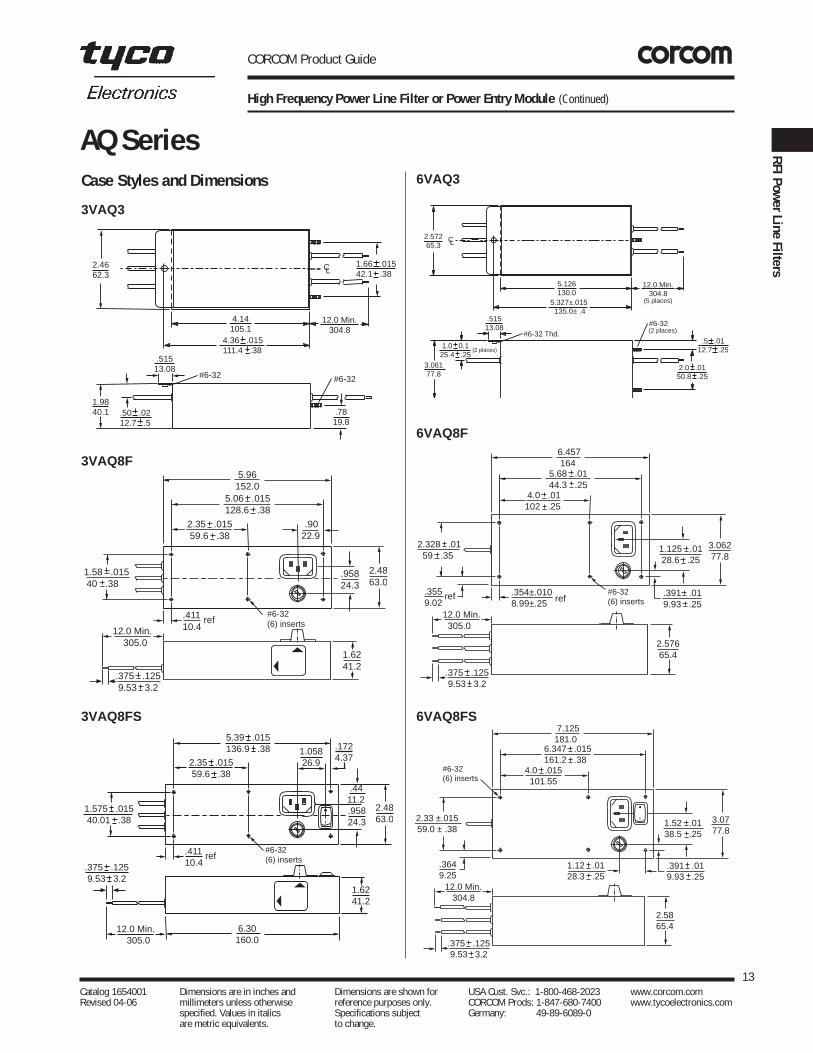
AQ SeriesCase Styles and Dimensions
2.4662.3
4.14105.1
4.36 .015111.4 .38
12.0 Min. 304.8
1.9840.1
1.66 .015 42.1 .38
.50 .0212.7 .5
#6-32
.515 13.08
#6-32
CL
.7819.8
.9022.9
2.35 .015 59.6 .38
5.06 .015128.6 .38
5.96152.0
.95824.3
1.58 .015 40 .38
.375 .125 9.53 3.2
2.4863.0
12.0 Min. 305.0
1.6241.2
.41110.4
ref#6-32(6) inserts
1.058 26.92.35 .015
59.6 .38
5.39 .015136.9 .38
.95824.3
1.575 .015 40.01 .38
.375 .125 9.53 3.2
2.4863.0
1.6241.2
.41110.4
ref#6-32(6) inserts
6.30 160.0
.4411.2
12.0 Min. 305.0
.1724.37
2.572 65.3
5.126130.0
5.327±.015 135.0± .4
12.0 Min. 304.8
3.061 77.8
.5 .0112.7 .25 1.0 0.1
25.4 .25
#6-32 .515 13.08
#6-32 Thd.
CL
(2 places)
2.0 .0150.8 .25
(5 places)
(2 places)
4.0 .01102 .25
5.68 .0144.3 .25
6.457 164
3.062 77.8
2.328 .01 59 .35
.375 .125 9.53 3.2
1.125 .01 28.6 .25
12.0 Min. 305.0
2.576 65.4
#6-32(6) inserts
.391 .019.93 .25
.354±.0108.99±.25 ref
.3559.02
ref
4.0 .015 101.55
6.347 .015161.2 .38
7.125181.0
3.0777.8
2.33 ±.01559.0 ± .38
.375 .125 9.53 3.2
1.52 .0138.5 .25
12.0 Min. 304.8
2.5865.4
#6-32(6) inserts
.391 .019.93 .25
.3649.25
1.12 .0128.3 .25
3VAQ3
6VAQ3
3VAQ8F
6VAQ8F
3VAQ8FS 6VAQ8FS

CORCOM Product Guide
Three Phase RFI Power Line Filters
The AYA series filters are designed for 3-phase, four-wire,WYE wiring applications. These cost-effective filters helpbetter protect electronic equipment in industrialapplications.
The series offers filtering up to 50 amps maximum and isused in 3-phase, industrial applications such asuninterruptible power supplies and industrial controlsystems. The AYA series is designed to comply withcurrent international standards.
SpecificationsMaximum leakage current, each line-to-ground
@ 120 VAC 60Hz 1.62mA@ 250 VAC 50 Hz 2.82mA
Hipot rating (one minute):line-to-ground 1500 VACline-to-line 1450 VDC
Operating frequency: 50/60 Hz
Operating voltage (max.): 440 VAC
Rated current:16AYA6-A 16A25AYA6-A 25A36AYA6-A 36A50AYA6-A 50A
Typical insertion loss in dB:
Line-to-ground in 50 ohm circuit
Current Frequency-MHzRating .01 .05 .1 .5 1 5 10 30
16A 2 11 19 52 53 70 61 3025A 2 12 19 46 49 64 54 2736A 1 10 18 49 54 63 57 3250A 1 8 14 43 47 63 53 29
Line-to-line in 50 ohm circuit
Current Frequency-MHzRating .01 .05 .1 .5 1 5 10 30
16A 14 31 30 82 87 76 77 4725A 20 36 38 85 81 68 69 3336A 20 39 36 86 78 65 62 3550A 20 30 38 85 82 67 66 38
14Catalog 1654001 Dimensions are in inches and Dimensions are shown for USA Cust. Svc.: 1-800-468-2023 www.corcom.com Revised 04-06 millimeters unless otherwise reference purposes only. CORCOM Prods: 1-847-680-7400 www.tycoelectronics.com
specified. Values in italics Specifications subject Germany: 49-89-6089-0 are metric equivalents. to change.
AYA Series
AYA Series
UL Recognized
Electrical Schematic
LINE LOADA
B
C
N
GND
A
B
C
N
GND
25AYA6A

CORCOM Product Guide
Three Phase RFI Power Line Filters (Continued)
Case Style Case Dimensions
Part No. A B C D E(max) (max) (max) (max) (max)
16/25 7.91 4.37 1.97 5.94 5.51201.0 111.0 50.0 151.0 140.0
36/50 7.91 4.37 2.56 5.94 5.51201.0 111.0 65.0 151.0 140.0
Part Numbers
16AYA6A25AYA6A36AYA6A50AYA6A
15Catalog 1654001 Dimensions are in inches and Dimensions are shown for USA Cust. Svc.: 1-800-468-2023 www.corcom.com Revised 04-06 millimeters unless otherwise reference purposes only. CORCOM Prods: 1-847-680-7400 www.tycoelectronics.com
specified. Values in italics Specifications subject Germany: 49-89-6089-0 are metric equivalents. to change.
RFI Pow
er Line Filters
AYA Series
AD
B
C
4.921±.020125.0±.5
E
2.756±.01270.0±.3
Terminals: 16/25: 8-32 (8) Torque (Max.): 14 in.lb.
36/50 1/4-20 (8)Torque (Max.): 56 in.lb. ± 2 in.lb.

CORCOM Product Guide
Three Phase RFI Power Line Filters for High Noise Applications
The AYC series filters are designed for 3-phase, four-wire,WYE wiring applications. These cost-effective filters helpbetter protect electronic equipment in industrialapplications.
The series offers filtering up to 180 amps maximum and isused in 3-phase, noisy industrial applications such asfrequency converters. The AYC series is designed tocomply with International Standards including EN133200and UL 1283.
16Catalog 1654001 Dimensions are in inches and Dimensions are shown for USA Cust. Svc.: 1-800-468-2023 www.corcom.com Revised 04-06 millimeters unless otherwise reference purposes only. CORCOM Prods: 1-847-680-7400 www.tycoelectronics.com
specified. Values in italics Specifications subject Germany: 49-89-6089-0 are metric equivalents. to change.
AYC Series
AYC Series
Electrical Schematic
LINE LOADA
B
C
N
GND
A
B
C
N
GND
SpecificationsMaximum leakage current, each line-to-ground
@ 120 VAC 60Hz:16A 62mA25/36A 68mA63/80/110/150A 74mA180A 111mA
@ 250 VAC 50 Hz:16A 106mA25/36A 118mA63A 128mA80/110/150A 129mA180A 192mA
Hipot rating (one minute):line-to-ground 1850 VDCline-to-line 1850 VDCline-to-neutral 1450 VDC
Operating frequency: 50/60 Hz
Operating voltage (max.): 480 VAC
Rated current:16AYC10B 16A 110AYC10B 110A25AYC10B 25A 150AYC10B 150A36AYC10B 36A 180AYC10B 180A63AYC10B 63A80AYC10B 80A
Typical insertion loss in dB:Line-to-ground in 50 ohm circuit
Current Frequency-MHzRating .01 .05 .1 .5 1 5 10 30
25A 26 68 83 93 88 68 45 436A 18 61 78 96 91 71 49 763A 11 57 72 90 86 68 44 4
110A 10 51 60 88 84 74 50 12150A* 0 50 57 82 79 75 51 7150A 1 51 55 85 82 84 51 11180A 3 53 55 97 89 81 56 20
Line-to-line in 50 ohm circuit
Current Frequency-MHzRating .01 .05 .1 .5 1 5 10 30
25A 23 33 60 100 95 87 70 3836A 25 37 51 94 87 69 58 1763A 27 45 41 84 77 63 61 43
110A 27 35 39 75 72 51 44 31150A* 28 37 42 74 67 52 45 30150A 28 40 42 73 66 51 44 31180A 30 41 50 70 64 49 42 26
*150AYC10B-95 only
UL RecognizedAYC10B

Case Dimensions
Part No. A B C D E± .078(max) (max) (max) (max)± 0.2
16AYC10B 6.69 4.37 2.56 4.92 2.76170.0 111.0 65.0 125.0 70.0
25AYC10B 9.96 5.08 2.52 5.71 4.53246.0 129.0 64.0 145.0 115.0
36AYC10B 10.35 5.08 2.52 5.71 4.53263.0 129.0 64.0 145.0 115.0
63AYC10B 10.89 5.08 2.52 5.71 4.53279.0 129.0 64.0 145.0 115.0
80/110/150 12.09 5.55 5.55 6.10 4.53AYC10B 307.0 141.0 141.0 155.0 115.0180AYC10B 15.71 5.55 5.55 6.10 3.25
399.0 141.0 141.0 155.0 82.5
Terminals
Part Numbers
16AYC10B 110AYC10B25AYC10B 150AYC10B36AYC10B 150AYC10B-9563AYC10B 180AYC10B80AYC10B
Type (qty.) Torque16AYC10B
Terminals M5 (2) 54 - 58 in. lb.Phoenix Contacts VDFK4 (8) 5.5 - 7.0 in. lb.
Accepts 12 AWG stranded wire. Strip length 0.31525AYC10B
Terminals M5 (2) 51 - 55 in. lb.Phoenix Contacts VDFK6 (8) 13.5 - 16 in. lb.
Accepts 10 AWG stranded wire. Strip length 0.35436AYC10B
Terminals M5 (2) 54 - 58 in. lb.Phoenix Contacts HDFK10 (8) 13.5 - 16 in. lb.
Accepts 8 AWG stranded wire. Strip length 0.43363AYC10B
Terminals M6 (2) 54 - 58 in. lb.Phoenix Contacts HDFK16 (8) 22 - 24.5 in. lb.
Accepts 6 AWG stranded wire. Strip length 0.63080/110/150AYC10B
Terminals M10 (2) 56 - 60 in. lb.Phoenix Contacts HDFK50 (8) 53 - 55 in. lb.
Accepts 1 AWG stranded wire. Strip length 0.945150AYC10B-95
Terminals M10 (2) 56 - 60 in. lb.Phoenix Contacts HDFK95 (8) 106-108 in. lb.
Accepts 0 AWG stranded wire. Strip length 1.063
CORCOM Product Guide
Three Phase RFI Power Line Filters for High Noise Applications (Continued)
Case Styles
17Catalog 1654001 Dimensions are in inches and Dimensions are shown for USA Cust. Svc.: 1-800-468-2023 www.corcom.com Revised 04-06 millimeters unless otherwise reference purposes only. CORCOM Prods: 1-847-680-7400 www.tycoelectronics.com
specified. Values in italics Specifications subject Germany: 49-89-6089-0 are metric equivalents. to change.
RFI Pow
er Line Filters
AYC Series
16, 25, 36, 63 AYC10B
80, 110, 150AYC10B / -95
180 AYC10B
B D
EA
C
B D
EA
C
B D
A
C
E E

CORCOM Product Guide
Lower Current Three Phase RFI Filters
SpecificationsMaximum leakage current, each line-to-ground:
3, 6, 10A 20A@ 120 VAC 60 Hz: 2.0 mA 3.5mA@ 250 VAC 50 Hz: 3.0 mA 5.5mA
Hipot rating (one minute):line-to-ground 1500 VACline-to-line 1450 VDC
Operating frequency: 50/60 Hz
Rated voltage (max.):phase-to-phase 440 VACphase-to-neutral/ground 250 VAC
Rated current:03AYO1 3A06AYO1 6A10AYO1 10A20AYO1 20A
Minimum insertion loss in dB:
Line-to-ground in 50 ohm circuit
Current Frequency-MHzRating .15 .5 1 5 10 30
03A 12 23 29 33 38 3506A 7 23 30 40 50 3010A – – 5 16 28 1520A – 7 11 32 23 12
Line-to-line in 50 ohm circuit
Current Frequency-MHzRating .15 .5 1 5 10 30
03A – 12 20 50 35 3006A 10 18 24 31 28 2810A 10 18 24 42 28 2220A 10 18 24 42 38 23
18Catalog 1654001 Dimensions are in inches and Dimensions are shown for USA Cust. Svc.: 1-800-468-2023 www.corcom.com Revised 04-06 millimeters unless otherwise reference purposes only. CORCOM Prods: 1-847-680-7400 www.tycoelectronics.com
specified. Values in italics Specifications subject Germany: 49-89-6089-0 are metric equivalents. to change.
AYO Series
AYO Series
UL RecognizedCSA CertifiedVDE Approved
The AYO series filters are designed for 3-phase, four wire,WYE applications providing filtering in each of the threelines plus neutral. These lower current RFI filters provide filtering to industrial3-phase applications.
Electrical Schematic
N N
LINE LOAD
AYO1

CORCOM Product Guide
Lower Current Three Phase RFI Filters (Continued)
Case Dimensions
Part No. A B C D E(max) (max) (max) ±.015 (max)
±.38
AYO 3.37 2.07 1.53 2.938 3.3585.6 52.5 38.7 74.63 85.1
Part Numbers
03AYO106AYO110AYO120AYO1
19Catalog 1654001 Dimensions are in inches and Dimensions are shown for USA Cust. Svc.: 1-800-468-2023 www.corcom.com Revised 04-06 millimeters unless otherwise reference purposes only. CORCOM Prods: 1-847-680-7400 www.tycoelectronics.com
specified. Values in italics Specifications subject Germany: 49-89-6089-0 are metric equivalents. to change.
RFI Pow
er Line Filters
AYO SeriesCase Style
A
B
C
D
E
Typical dimensions:Terminals: .250 [6.35] (9) Holes: .07 [1.8] Dia.(8) Slot: .07 x .16 [1.8 x 4.1] Mounting holes: .188 [4.78] Dia.(2)

CORCOM Product Guide
General Purpose RFI Power Line Filters for High Impedance Loads at Low Cost
The B series RFI power line filters are general purposecommon-mode filters effectively providing RFI controlof line-to-ground noise in a small size at low cost.These filters are designed to meet a wide variety ofelectronic and electrical applications and are availablein a broad selection of current ratings and terminationstyles.
The EB models meet the very low leakage currentrequirements of VDE portable equipment, and (120 Volt)UL544 non-patient medical equipment.
20Catalog 1654001 Dimensions are in inches and Dimensions are shown for USA Cust. Svc.: 1-800-468-2023 www.corcom.com Revised 04-06 millimeters unless otherwise reference purposes only. CORCOM Prods: 1-847-680-7400 www.tycoelectronics.com
specified. Values in italics Specifications subject Germany: 49-89-6089-0 are metric equivalents. to change.
B Series
B Series
UL RecognizedCSA CertifiedVDE Approved
Electrical Schematic
LINE LOAD
Resistor location for reference only.
SpecificationsMaximum leakage current, each line-to-ground
VB Models EB Models@ 120 VAC 60 Hz: .4 mA .21 mA@ 250 VAC 50 Hz: .7 mA .36 mA
Hipot rating (one minute):
line-to-ground 2250 VDCline-to-line 1450 VDC
Operating frequency: 50/60 Hz
Rated voltage (max.): 250 VAC
Rated current:1VB/1EB 1A2VB/2EB 2A3VB/3EB 3A5VB/5EB 5A
10VB/10EB 10A10VB6 10A20VB/20EB 20A30VB6 30A
Minimum insertion loss in dB:
Line-to-ground in 50 ohm circuit
Current Frequency-MHzRating .15 .5 1 5 10 30
VB Models1A, 3A 15 30 38 50 50 502A, 5A, 10A, 20A, 30A 7 20 25 40 45 48
EB Models1A, 3A 15 29 35 45 45 482A, 5A, 10A, 20A 7 19 23 34 37 42
VB1/EB1VB3/EB3
10VB6/20VB6

CORCOM Product Guide
General Purpose RFI Power Line Filters for High Impedance Loads at Low Cost (Continued)
Case Styles Case DimensionsA B C D E
Part No. (max) (max) (max) ±.015 (max)±.38
1VB1, 1EB1, 2.25 1.82 0.66 2.125 2.532VB1, 2EB1 57.2 46.2 16.8 53.98 64.31VB3, 1EB3, 0.96 1.82 0.66 2.125 2.532VB3, 2EB3 24.4 46.2 16.8 53.98 64.33VB1, 3EB1, 2.61 1.82 0.78 2.125 2.535VB1, 5EB1 66.3 46.2 19.8 53.98 64.33VB3, 3EB3, 1.32 1.82 0.78 2.125 2.535VB3, 5EB3 33.5 46.2 19.8 53.98 64.3
10VB1, 10EB1 2.61 1.82 1.16 2.125 2.5366.3 46.2 29.5 53.98 64.3
10VB3, 10EB3 1.32 1.82 1.16 2.125 2.5333.5 46.2 29.5 53.98 64.3
10VB6 2.72 1.82 1.16 2.125 2.5369.1 46.2 29.5 53.98 64.3
20VB1, 20EB1 3.36 2.07 1.16 2.375 2.8185.3 52.6 29.5 60.33 71.4
20VB6 3.46 2.07 1.16 2.375 2.8187.9 52.6 29.5 60.33 71.4
30VB6 5.34 3.38 1.53 3.750 4.20135.6 85.9 38.9 95.3 106.7
21Catalog 1654001 Dimensions are in inches and Dimensions are shown for USA Cust. Svc.: 1-800-468-2023 www.corcom.com Revised 04-06 millimeters unless otherwise reference purposes only. CORCOM Prods: 1-847-680-7400 www.tycoelectronics.com
specified. Values in italics Specifications subject Germany: 49-89-6089-0 are metric equivalents. to change.
RFI Pow
er Line Filters
B Series
B1
B3
10VB6 & 20VB6
30VB6
E D B
A CTypical dimensions:
Terminals: .250 [6.35] (5) Holes: .07 [1.8] Dia.(4) Slot: .07 x .16 [1.8 x 4.1] Mounting holes: .188 [4.78] Dia.(2)
Typical dimensions:Wire Leads: 4.0 [101.6] Min. Mounting holes: .188 [4.78] Dia.(2)
Typical dimensions:Mounting holes: .188 [4.78] Dia.(2) Torque: 18±2 in. lb.
E D B
A C
Blue Blue
Brown
Green/Yellow
Brown
E D B
Terminals:No. 8-32 (5)
A C
E D B
2.0050.8
A
Terminals: No. 8-32 (5)
C
Slots: .2506.35
.156 3.96
x (4)
Part Numbers
01VB1 01EB101VB3 01EB302VB1 02EB102VB3 02EB303VB1 03EB103VB3 03EB305VB1 05EB105VB3 05EB310VB1 10EB110VB3 10EB310VB6 20EB120VB120VB630VB6

CORCOM Product Guide
Enhanced Performance K Series RFI Power Line Filters
The DK series RFI power line filters are generalpurpose common mode and differential mode filterswith higher performance line-to-line attenuation thanthe VK series.
The E version of the DK series (EDK) has the same highperformance line-to-line attenuation while still meeting thevery low leakage current requirements of VDE portableequipment and UL544 non-patient care equipment.
The V version of the DK series (VDK) has the same highperformance in a more cost-effective package forapplications without strict leakage current requirements.
SpecificationsMaximum leakage current, each line-to-ground
VDK Models EDK Models@ 120 VAC 60 Hz: .4 mA .22 mA@ 250 VAC 50 Hz: .7 mA .38 mA
Hipot rating (one minute):
line-to-ground 2250 VDCline-to-line 1450 VDC
Operating frequency: 50/60 Hz
Rated voltage (max.): 250 VAC
Rated current:1VDK/1EDK 1A3VDK/3EDK 3A6VDK/6EDK 6A
10VDK/10EDK 10A20VDK/20EDK 20A
Minimum insertion loss in dB:Line-to-ground in 50 ohm circuit
Current Frequency-MHzRating .15 .5 1 5 10 30
VDK Models1A, 3A 18 30 40 48 48 406A, 10A, 20A 10 22 30 39 44 50
EDK Models1A, 3A 17 27 33 45 45 406A, 10A, 20A 10 19 25 34 40 46
Line-to-line in 50 ohm circuit
Current Frequency-MHzRating .15 .5 1 5 10 30
VDK, EDK Models1A, 3A 18 47 62 60 50 456A, 10A, 20A 20 43 55 65 60 55
22Catalog 1654001 Dimensions are in inches and Dimensions are shown for USA Cust. Svc.: 1-800-468-2023 www.corcom.com Revised 04-06 millimeters unless otherwise reference purposes only. CORCOM Prods: 1-847-680-7400 www.tycoelectronics.com
specified. Values in italics Specifications subject Germany: 49-89-6089-0 are metric equivalents. to change.
DK Series
DK Series
DK6
DK3
DK1
UL RecognizedCSA CertifiedVDE Approved
Electrical Schematic
LINE LOAD
Resistor location for reference only.
DK1

CORCOM Product Guide
Enhanced Performance K Series RFI Power Line Filters (Continued)
Case Styles
Case DimensionsA B C D E
Part No. (max) (max) (max) ±.015 (max)±.38
1VDK1, 1EDK1 3.35 2.07 1.16 2.375 2.8185.1 52.6 29.5 60.33 71.4
1VDK3, 1EDK3 2.07 2.07 1.16 2.375 2.8152.6 52.6 29.5 60.33 71.4
3VDK1, 3EDK1, 3.85 2.07 1.16 2.938 3.356VDK1, 6EDK1 97.8 52.6 29.5 74.63 85.13VDK3, 3EDK3, 2.56 2.07 1.16 2.938 3.356VDK3, 6EDK3 65.0 52.6 29.5 74.63 85.110VDK1, 3.85 2.07 1.32 2.938 3.3510EDK1 97.8 52.6 33.5 74.63 85.110VDK3, 2.57 2.07 1.32 2.938 3.3510EDK3 65.3 52.6 33.5 74.63 85.120VDK1, 3.85 2.58 1.78 2.938 3.3520EDK1 97.8 65.5 45.2 74.63 85.1
20VDK6 3.46 2.58 1.78 2.938 3.3587.9 65.5 45.2 74.63 85.1
23Catalog 1654001 Dimensions are in inches and Dimensions are shown for USA Cust. Svc.: 1-800-468-2023 www.corcom.com Revised 04-06 millimeters unless otherwise reference purposes only. CORCOM Prods: 1-847-680-7400 www.tycoelectronics.com
specified. Values in italics Specifications subject Germany: 49-89-6089-0 are metric equivalents. to change.
RFI Pow
er Line Filters
DK Series
VDK1/EDK1
VDK3/EDK3
20VDK1/20EDK1
20VDK6
E
D
A
B
C
E
D
A
C
B
Green/Yellow
Blue
Brown
Blue
Brown
E D
A
B
C
E D
A
B
C
Terminals:No. 8-32 (5)
Part Numbers
01VDK1 01EDK101VDK3 01EDK303VDK1 03EDK103VDK3 03EDK306VDK1 06EDK106VDK3 06EDK310VDK1 10EDK110VDK3 10EDK320VDK1 20EDK120VDK6
Torque 18± 2 in.lb.
Typical dimensions:Terminals: .250 [6.35] (5) Holes: .07 [1.8] Dia.(4)Mounting Holes: .188 [4.78] Dia. (2) Slot: .07 x .16 [1.8 x 4.1]
Typical dimensions:Wire Leads: 4.0 [101.6] (Min.) Mounting Holes: .188 [4.78] Dia. (2)
Typical dimensions:Terminals: .250 [6.35] (5) Holes: .07 [1.8] Dia.(4)Mounting Holes: .188 [4.78] Dia. (2) Slot: .07 x .16 [1.8 x 4.1]

CORCOM Product Guide
For UL544 Health Care Equipment
This is a new generation of compact medical RFI filters with an IEC socket. A new design in internal structure andmanufacturing process makes this series cost effective.This health care series supersedes the H series byproviding superior differential mode performance while stillmaintaining a maximum leakage current of 2 micro amps.
EBH SeriesAlso a compact medical RFI filter with IEC socket, the EBHseries is a cost effective alternative to the H series.Electrically the EBH provides enhanced differential modeperformance compared to both the EAH and the H series.These filters provide RFI common and differential modeperformance while still allowing medical equipment to meet UL leakage current specifications for medical anddental equipment.
Additional information on UL544 specification is listed in Appendix C.
Note: When using the models with an IEC connector,remember that the leakage current of the companion linecord, GA400, is more significant than that of the filter -which may disqualify this line cord from use in patient care applications.
SpecificationsMaximum leakage current,each line-to-ground
@ 120 VAC 60 Hz: 2 µA@ 250 VAC 50 Hz: 5 µA
Hipot rating (one minute):
line-to-ground 1500 VACline-to-line 1450 VDC
Operating frequency: 50/60 Hz
Rated voltage (max.): 250 VAC
Minimum insertion loss in dB:
Line-to-ground in 50 ohm circuitCurrent Frequency-MHzRating .01 .05 .1 .15 .5 1 5 10 30
EAH Models01A 8 21 29 32 42 45 32 30 1903A - 5 10 15 25 27 30 27 2206A - - 5 6 19 21 24 20 1510A - - 1 5 9 12 12 12 12
EBH Models01A 8 21 29 32 42 45 32 25 1903A - 5 10 15 25 27 30 27 2206A - - 5 8 17 20 24 23 1810A - - - 3 8 12 12 12 12
Line-to-line in 50 ohm circuit
Current Frequency-MHzRating 1 1.5 5 10 30
EAH Models01A 5 13 28 32 253A 4 6 20 27 28
06A 2 5 19 25 2710A 1 5 15 22 27
Current Frequency-MHzRating .15 .5 1 5 10 30
EBH ModelsAll Ratings 1 10 18 30 31 31
24Catalog 1654001 Dimensions are in inches and Dimensions are shown for USA Cust. Svc.: 1-800-468-2023 www.corcom.com Revised 04-06 millimeters unless otherwise reference purposes only. CORCOM Prods: 1-847-680-7400 www.tycoelectronics.com
specified. Values in italics Specifications subject Germany: 49-89-6089-0 are metric equivalents. to change.
EAH, EBH Series
EAH Series
Electrical Schematic
LINE LOAD
Resistor location for reference only.
UL RecognizedCSA CertifiedVDE Approved EAH1/EBH1

CORCOM Product Guide
For UL544 Health Care Equipment (Continued)
Case Style
Recommended Panel Cutouts
Case Dimensions
Part No. A B C D E(max) (max) (max) ±.010 (max)
±.25
EAH1 2.15 1.12 .90 1.575 1.9854.61 28.45 22.86 40.01 50.29
EBH1 2.15 1.12 .90 1.575 1.9854.61 28.45 22.86 40.01 50.29
25Catalog 1654001 Dimensions are in inches and Dimensions are shown for USA Cust. Svc.: 1-800-468-2023 www.corcom.com Revised 04-06 millimeters unless otherwise reference purposes only. CORCOM Prods: 1-847-680-7400 www.tycoelectronics.com
specified. Values in italics Specifications subject Germany: 49-89-6089-0 are metric equivalents. to change.
RFI Pow
er Line Filters
EAH, EBH Series
E
C
D
A
B
.1403.56
.123.0
Panel cutout for front mounting
.82020.8
R
Dia. (2)1.1429.96
1.57540.01
.1403.56
.2345.94
Panel cutout for back mounting
.90022.9
R
Dia. (2)1.20030.48
1.57540.01
.1403.56
.123.0
Panel cutout for front mounting
.82020.8
R
Dia. (2)1.1429.96
1.57540.01
.1403.56
.2345.94
Panel cutout for back mounting
.90022.9
R
Dia. (2)1.20030.48
1.57540.01
EAH1/EBH1
Part Numbers
01EAH1 01EBH103EAH1 03EBH106EAH1 06EBH110EAH1 10EBH1
Line Cord No. GA400Insulating Boot No. FA601
Panel Cutout (Front mount)
Panel Cutout (Back mount)
Typical dimensions:Terminals: .250 [6.35] (5) Holes: .07 [1.8] Dia.(2)Slot: .07 x .16 [1.8 x 4.1] Mounting Holes: .132 [3.35] Dia. (2) with .260 Dia.
x 90˚ countersunk for #4 Flathead Screw
Tolerance ±.005 [0.13]
Tolerance ±.005 [0.13]

CORCOM Product Guide
Snap-In Compact RFI Filter IEC Connector Package
This filter offers the performance characteristics of the EEA susceptibility filter with the additional advantage of asnap-in panel mount. The EAS series supersedes the EFseries by providing superior performance, particularly inthe common mode at low frequencies.
EBS SeriesThis filter offers the performance characteristics of the EEB susceptibility filter with the additional advantage of a snap-in panel mount. The EBS provides enhanceddifferential mode performance compared to both the EAS and EF series.
SpecificationsMaximum leakage current,each line-to-ground
@ 120 VAC 60 Hz: .22 mA@ 250 VAC 50 Hz: .38 mA
Hipot rating (one minute):
line-to-ground 1500 VACline-to-line 1450 VDC
Operating frequency: 50/60 Hz
Rated voltage (max.): 250 VAC
Minimum insertion loss in dB:Line-to-ground in 50 ohm circuit
Current Frequency-MHzRating .01 .05 .1 .15 .5 1 5 10 30
EAS Models01A 12 23 29 32 41 47 47 47 4003A - 10 15 19 30 36 48 50 4706A - 1 4 10 22 28 42 48 4710A - 1 3 5 14 20 32 38 4715A - - - 1 5 8 20 25 40
EBS Models01A 12 23 29 32 41 47 47 47 4003A - 10 14 18 30 36 48 50 4706A - 1 4 10 22 28 42 48 4710A - 1 3 5 14 20 32 38 4715A - - - 1 5 8 20 26 40
Line-to-line in 50 ohm circuitCurrent Frequency-MHzRating .5 1 1.5 3 5 10 30
EAS Models01A 1 9 19 32 42 45 4003A 2 4 6 20 35 45 4006A 2 4 6 6 24 40 4010A 1 4 5 5 5 30 4015A 1 4 4 12 14 15 40
Current Frequency-MHzRating .01 .15 .5 1 3 5 10 30
EBS Models1A 1 3 14 23 41 47 50 443A 1 2 11 14 25 38 44 406A 1 2 10 14 20 33 42 40
10A 1 2 10 16 19 19 39 4015A - 2 10 16 24 28 28 40
26Catalog 1654001 Dimensions are in inches and Dimensions are shown for USA Cust. Svc.: 1-800-468-2023 www.corcom.com Revised 04-06 millimeters unless otherwise reference purposes only. CORCOM Prods: 1-847-680-7400 www.tycoelectronics.com
specified. Values in italics Specifications subject Germany: 49-89-6089-0 are metric equivalents. to change.
EAS, EBS Series
EAS Series
Electrical Schematic
Resistor location for reference only.
LINE LOAD
UL RecognizedCSA CertifiedVDE Approved
EAS1/EBS1

Case Style
Recommended Panel Cutout
CORCOM Product Guide
Snap-In Compact RFI Filter IEC Connector Package (Continued)
Case DimensionsA B C D E
Part No. (max) (max) (max) ± .010 (max)± .25
EAS1 2.20 1.15 .96 1.18 1.4155.88 29.2 24.38 29.97 35.81
EBS1 2.20 1.15 .96 1.185 1.3555.88 29.2 24.38 30.10 34.21
27Catalog 1654001 Dimensions are in inches and Dimensions are shown for USA Cust. Svc.: 1-800-468-2023 www.corcom.com Revised 04-06 millimeters unless otherwise reference purposes only. CORCOM Prods: 1-847-680-7400 www.tycoelectronics.com
specified. Values in italics Specifications subject Germany: 49-89-6089-0 are metric equivalents. to change.
RFI Pow
er Line Filters
EAS, EBS Series
E
D
C
A
B
EAS1/EBS1
R 0.188 [4.78](4X)
.81520.70
G±.002 [.05]
Front Mount Only
Part Numbers
01EAS1 01EBS103EAS1 03EBS106EAS1 06EBS110EAS1 10EBS115EAS1 15EBS1
Line Cord No. GA400Insulating Boot No. FA601
Typical dimensions:Terminals: .250 [6.35] (3) Holes: .07 [1.8] Dia.(2)Slot: .07 x .16 [1.8 x 4.1]
Panel Thickness G Dim.±.0020.031 - 0.052 [.79 - 1.32] 1.260 [32.00]0.046 - 0.068 [1.17 - 1.73] 1.350 [34.29]

CORCOM Product Guide
Accessory Outlet Filter
The EBF accessory outlet filters provides an innovativemeans of connecting accessories while filtering noisebetween a system and the accessories attached. Thesefilters provide enhanced performance utilizing commonmode inductance and differential mode capacitance forattenuation of noise across the frequency range.
The filtered connector offers the additional advantage of a grounded connection and features low leakage currentrequired for international usage.
SpecificationsMaximum leakage current,each line-to-ground
@ 120 VAC 60 Hz: .25 mA@ 250 VAC 50 Hz: .50 mA
Hipot rating (one minute):line-to-ground 1500 VACline-to-line 1450 VDC
Operating frequency: 50/60 Hz
Rated voltage (max.): 250 VACMinimum insertion loss in dB:Line-to-ground in 50 ohm circuit
Current Frequency-MHzRating .05 .15 .5 1 5 10 30
1A 23 32 41 47 47 47 403A 10 19 30 36 48 50 476A 1 10 22 28 42 48 4710A 1 5 14 20 32 38 47
Line-to-line in 50 ohm circuit
Current Frequency-MHzRating .15 .5 1 3 5 10 30
1A 3 14 23 41 47 50 443A 2 11 14 25 38 44 406A 2 10 14 20 33 42 40
10A 2 10 16 19 19 39 40
28Catalog 1654001 Dimensions are in inches and Dimensions are shown for USA Cust. Svc.: 1-800-468-2023 www.corcom.com Revised 04-06 millimeters unless otherwise reference purposes only. CORCOM Prods: 1-847-680-7400 www.tycoelectronics.com
specified. Values in italics Specifications subject Germany: 49-89-6089-0 are metric equivalents. to change.
EBF Series
EBF Series
Electrical Schematic
LINE ACCESSORYOUTLET
Resistor location for reference only.
EBF4
EBF1UL RecognizedCSA CertifiedVDE Approved

CORCOM Product Guide
Accessory Outlet Filter (Continued)
Case Styles
EBF1
EBF4
Recommended Panel Cutout
Case DimensionsA B C D E
± .010Part No. (max) (max) (max) (max)± .25
EBF1 2.57 1.33 1.10 1.575 1.9965.3 33.8 25.4 40.01 50.5
EBF4 2.09 1.39 1.16 1.575 1.9953.01 35.31 29.46 40.01 50.5
29Catalog 1654001 Dimensions are in inches and Dimensions are shown for USA Cust. Svc.: 1-800-468-2023 www.corcom.com Revised 04-06 millimeters unless otherwise reference purposes only. CORCOM Prods: 1-847-680-7400 www.tycoelectronics.com
specified. Values in italics Specifications subject Germany: 49-89-6089-0 are metric equivalents. to change.
RFI Pow
er Line Filters
EBF Series
ADE B
0.126 Dia.
CC
ED
C
A B
Wire 18 AWG 10" length
.143.6
.205.1
1.01*25.7
R Typ.
Dia.1.4035.6
1.575 ± .00440.0 ± 0.1
* +.008-.000
Front mount only
Part Numbers
01EBF1 01EBF403EBF1 03EBF406EBF1 06EBF410EBF1 10EBF4
Typical dimensions:Terminals: .250 [6.35] (3) Holes: .07 [1.8] Dia.(2)Slot: .07 x .16 [1.8 x 4.1] Mounting Holes: .132 [3.35] Dia. (2) with .250 Dia.
x 90˚ countersunk for #4 Flathead Screw
CORCOM Product Guide
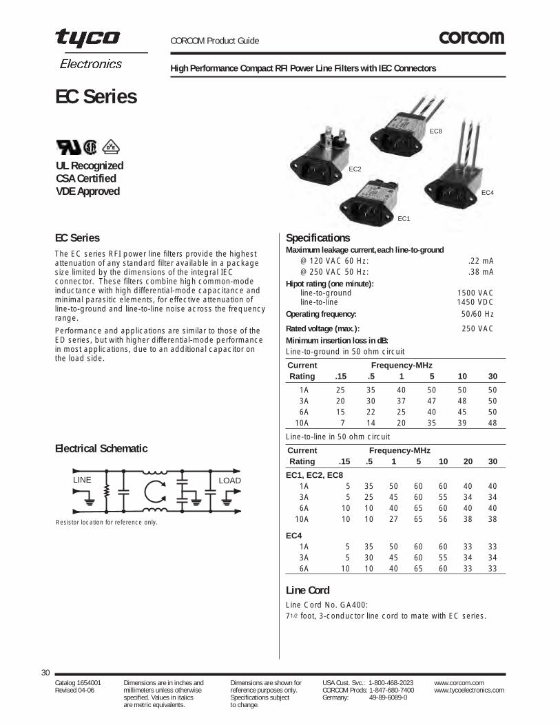
High Performance Compact RFI Power Line Filters with IEC Connectors
The EC series RFI power line filters provide the highestattenuation of any standard filter available in a packagesize limited by the dimensions of the integral IECconnector. These filters combine high common-modeinductance with high differential-mode capacitance andminimal parasitic elements, for effective attenuation of line-to-ground and line-to-line noise across the frequencyrange.
Performance and applications are similar to those of the ED series, but with higher differential-mode performance in most applications, due to an additional capacitor on the load side.
SpecificationsMaximum leakage current,each line-to-ground
@ 120 VAC 60 Hz: .22 mA@ 250 VAC 50 Hz: .38 mA
Hipot rating (one minute):line-to-ground 1500 VACline-to-line 1450 VDC
Operating frequency: 50/60 Hz
Rated voltage (max.): 250 VACMinimum insertion loss in dB:Line-to-ground in 50 ohm circuit
Current Frequency-MHzRating .15 .5 1 5 10 30
01A 25 35 40 50 50 5003A 20 30 37 47 48 5006A 15 22 25 40 45 5010A 7 14 20 35 39 48
Line-to-line in 50 ohm circuit
Current Frequency-MHzRating .15 .5 1 5 10 20 30
EC1, EC2, EC801A 5 35 50 60 60 40 4003A 5 25 45 60 55 34 3406A 10 10 40 65 60 40 4010A 10 10 27 65 56 38 38
EC401A 5 35 50 60 60 33 3303A 5 30 45 60 55 34 3406A 10 10 40 65 60 33 33
Line CordLine Cord No. GA400:71/2 foot, 3-conductor line cord to mate with EC series.
30Catalog 1654001 Dimensions are in inches and Dimensions are shown for USA Cust. Svc.: 1-800-468-2023 www.corcom.com Revised 04-06 millimeters unless otherwise reference purposes only. CORCOM Prods: 1-847-680-7400 www.tycoelectronics.com
specified. Values in italics Specifications subject Germany: 49-89-6089-0 are metric equivalents. to change.
EC Series
EC Series
Electrical Schematic
Resistor location for reference only.
LINE LOAD
EC1
EC8
EC2
EC4
UL RecognizedCSA CertifiedVDE Approved

CORCOM Product Guide
High Performance Compact RFI Power Line Filters with IEC Connectors (Continued)
Case StylesEC1
EC2
EC4
EC8
Case DimensionsA B C D E F
Part No. (max) (max) (max) ± .015 (max) (ref)± .38
1EC1 2.62 1.19 0.81 1.575 1.98 —66.5 30.2 20.6 40.01 50.3
1EC2 1.97 1.19 0.85 1.575 1.98 —50.0 30.2 21.6 40.01 50.3
1EC4 1.97 1.19 0.85 1.575 1.98 .29550.0 30.2 21.6 40.01 50.3 7.5
1EC8 1.98 1.19 0.81 1.575 1.98 .29550.3 30.2 20.6 40.01 50.3 7.5
3EC1 2.62 1.19 0.81 1.575 1.98 —66.5 30.2 20.6 40.01 50.3
3EC2 1.97 1.19 0.85 1.575 1.98 —50.0 30.2 21.6 40.01 50.3
3EC4 1.97 1.19 0.85 1.575 1.98 .29550.0 30.2 21.6 40.01 50.3 7.5
3EC8 1.98 1.19 0.81 1.575 1.98 .29550.3 30.2 20.6 40.01 50.3 7.5
6EC1 2.62 1.19 0.81 1.575 1.98 —66.5 30.2 20.6 40.01 50.3
6EC2 1.97 1.19 0.85 1.575 1.98 —50.0 30.2 21.6 40.01 50.3
6EC4 1.97 1.19 0.85 1.575 1.98 .29550.0 30.2 21.6 40.01 50.3 7.5
6EC8 1.98 1.19 0.81 1.575 1.98 .29550.3 30.2 20.6 40.01 50.3 7.5
10EC1 2.62 1.19 0.81 1.575 1.98 —66.5 30.2 20.6 40.01 50.3
31Catalog 1654001 Dimensions are in inches and Dimensions are shown for USA Cust. Svc.: 1-800-468-2023 www.corcom.com Revised 04-06 millimeters unless otherwise reference purposes only. CORCOM Prods: 1-847-680-7400 www.tycoelectronics.com
specified. Values in italics Specifications subject Germany: 49-89-6089-0 are metric equivalents. to change.
RFI Pow
er Line Filters
EC Series
Part Numbers
1EC1 06EC11EC2 06EC21EC4 06EC41EC8 06EC83EC1 10EC13EC23EC43EC8
Line Cord No. GA400Insulating Boot No. FA601
A
C
B
D
E
DE A
C
B
.6516.5
Max.
C
A
F
F
B
Bro
wn
Gre
en/Y
ello
w
Blu
e
D
E
Blue
Green/Yellow
BrownB
F
F
D E
C
A
.1403.56
.0621.58
.82020.8
R
Dia. (2)1.20030.48
1.57540.01
.1403.56
.2345.94
.90022.9
R
Dia. (2)1.20030.48
1.57540.01
Note 1: EC1 and EC8 allow front or back mounting.Note 2: EC2 and EC4 allow back mounting only.
Tolerance ±.005 [0.13] Tolerance ±.005 [0.13]
Panel Cutout (front mount) Panel Cutout (back mount)
Recommended Panel Cutouts
Typical dimensions:Terminals: .250 [6.35] (3) Holes: .07 [1.8] Dia.(2)Slot: .07 x .16 [1.8 x 4.1]
Typical dimensions:Wire Leads: 4.0 [101.6] Min. 18 AWG Mounting holes: .132 [3.35] Dia. (2)

CORCOM Product Guide
High Performance Compact RFI Power Line Filters with IEC Connectors
The ED series filters are more effective than general-purpose filters in applications where line-to-line and low-frequency line-to-ground noise must be controlled; forexample, to bring equipment into compliance with FCCconducted emissions standards.
The ED series offers significantly higher performance than comparably sized filters, especially at highfrequencies, yet is in the EF series package whichincorporates the IEC power line connector. Models ED1,ED1C, and ED2 have .250” terminals on load side; ED4,ED4C, ED8, and ED8C have wire leads.
Models 6ED1C, 10ED1C, 6ED4C, and 6ED8C additionallyincorporate a separate ground-circuit inductor to isolate the equipment chassis from power line ground at RFfrequencies.
SpecificationsMaximum leakage current,each line-to-ground
@ 120 VAC 60 Hz: .22 mA@ 250 VAC 50 Hz: .38 mA
Hipot rating (one minute):line-to-ground 1500 VACline-to-line 1450 VDC
Operating frequency: 50/60 Hz
Rated voltage (max.): 250 VACMinimum insertion loss in dB:Line-to-ground in 50 ohm circuit
Current Frequency-MHzRating .15 .5 1 5 10 30
ED1, ED2, ED4, ED801A 24 35 42 49 52 5403A 20 29 36 45 50 5406A 14 23 30 41 45 5010A 8 14 20 35 39 4515A 4 9 12 28 34 40
ED1C06A 14 20 25 37 42 5010A 8 14 20 35 39 45
ED4C, ED8C06A 14 20 25 37 42 50
Line-to-line in 50 ohm circuit
Current Frequency-MHzRating .15 .5 1 5 10 30
ED1, ED2, ED4, ED801A 3 15 20 37 37 3603A 3 15 20 37 37 3606A 3 15 20 31 35 3410A 6 15 20 23 44 4715A 6 18 23 33 44 47
ED1C06A 7 17 23 36 42 4210A 6 15 20 23 44 47
ED4C, ED8C06A 7 17 23 29 38 42
32Catalog 1654001 Dimensions are in inches and Dimensions are shown for USA Cust. Svc.: 1-800-468-2023 www.corcom.com Revised 04-06 millimeters unless otherwise reference purposes only. CORCOM Prods: 1-847-680-7400 www.tycoelectronics.com
specified. Values in italics Specifications subject Germany: 49-89-6089-0 are metric equivalents. to change.
ED Series
ED Series
ED1/ED1C
ED2
ED4/ED4C
ED8/ED8C
Electrical Schematics
LINE LOAD
LINE LOAD
Resistor location for reference only.
ED Models
ED-C Models
Line CordLine Cord No. GA400:71/2 foot, 3-conductor line cord to mate with ED series.
UL RecognizedCSA CertifiedVDE Approved
*15ED1, 15ED8 - UL, CSA 15 Amps/250 VACVDE 10 Amps/250 VAC

CORCOM Product Guide
High Performance Compact RFI Power Line Filters with IEC Connectors (Continued)
Case StylesED1 & ED1C
ED2
ED4 &ED4C
ED8 & ED8C
Case Dimensions
A B C D E F± .015Part No. (max) (max) (max) (max) (ref)± .38
1ED1, 2.21 1.19 0.81 1.575 1.98 —3ED1 56.0 30.2 20.6 40.01 50.31ED2, 1.55 1.19 0.85 1.575 1.98 —3ED2 39.4 30.2 21.6 40.01 50.31ED4, 1.55 1.19 0.85 1.575 1.98 .2953ED4 39.4 30.2 21.6 40.01 50.3 7.51ED8, 1.55 1.19 0.81 1.575 1.98 .2953ED8 39.4 30.2 20.6 40.01 50.3 7.5
6ED1 2.21 1.19 0.81 1.575 1.98 —56.0 30.2 20.6 40.01 50.3
6ED1C 2.62 1.19 0.81 1.575 1.98 —66.5 30.2 20.6 40.01 50.3
6ED2 1.55 1.19 0.85 1.575 1.98 —39.4 30.2 21.6 40.01 50.3
6ED4 1.55 1.19 0.85 1.575 1.98 .29539.4 30.2 21.6 40.01 50.3 7.5
6ED4C 1.98 1.19 0.85 1.575 1.98 .29550.3 30.2 21.6 40.01 50.3 7.5
6ED8 1.55 1.19 0.81 1.575 1.98 .29539.4 30.2 20.6 40.01 50.3 7.5
6ED8C 1.98 1.19 0.81 1.575 1.98 .29550.3 30.2 20.6 40.01 50.3 7.5
10ED1, 2.62 1.19 0.81 1.575 1.98 —15ED1* 66.5 30.2 20.6 40.01 50.3
10ED1C 2.62 1.19 0.81 1.575 1.98 —66.5 30.2 20.6 40.01 50.3
15ED8* 1.98 1.19 0.81 1.575 1.98 —50.3 30.2 20.6 40.01 50.3
33Catalog 1654001 Dimensions are in inches and Dimensions are shown for USA Cust. Svc.: 1-800-468-2023 www.corcom.com Revised 04-06 millimeters unless otherwise reference purposes only. CORCOM Prods: 1-847-680-7400 www.tycoelectronics.com
specified. Values in italics Specifications subject Germany: 49-89-6089-0 are metric equivalents. to change.
RFI Pow
er Line Filters
ED Series
Part Numbers
1ED1 06ED21ED2 06ED41ED4 06ED4C1ED8 06ED83ED1 06ED8C3ED2 10ED13ED4 10ED1C3ED8 15ED1*6ED1 15ED8*6ED1C
Line Cord No. GA400Insulating Boot No. FA601
*15ED1, 15ED8 - UL, CSA 15 Amps/250 VACVDE 10 Amps/250 VAC
A
C
BD
E
DE A
C
B
.6516.5
Max.
C
A
F
F
B
Bro
wn
Gre
en/Y
ello
w
Blu
e
D
E
Blue
Green/Yellow
Brown
B
C
F
F
D E
A
Typical dimensions:Terminals: .250 [6.35] (3) Holes: .07 [1.8] Dia.(2) Slot: .07 x .16 [1.8 x 4.1]
.1403.56
.0621.58
.82020.8
R
Dia. (2)1.20030.48
1.57540.01
.1403.56
.2345.94
.90022.9
R
Dia. (2)1.20030.48
1.57540.01
Recommended Panel Cutouts
Panel Cutout (back mount)Panel Cutout (front mount)Tolerance ±.005 [0.13]Tolerance ±.005 [0.13]
Note 1: ED1, ED1C, ED8 and ED8C allow front or back mounting.Note 2: ED2, ED4 and ED4C allow back mounting only.
Typical dimensions:Wire leads:4.0 [101.6] Min., 18 AWG Mounting holes: .132 [3.35] Dia. (2)

CORCOM Product Guide
PC Board Mountable RFI Filters for General Purpose Applications
The EDP series RFI filters provide enhanced differentialmode performance for applications requiring more line-to-line protection. The EDP filters feature low leakage currentfor European safety requirements.
PC board mounted and only slightly taller than the EOPseries filters, the EDP filters are available up to 10 amps.
EOP SeriesThe EOP series RFI power line filters are general purposefilters which are effective in removing both common anddifferential mode noise for susceptibility applications.These filters have low leakage current for European safety requirements.
The compact design allows PC board mounting withminimal space requirements. Available from 1 to 10 amps,the filters provide a cost effective alternative to on boardcomponents.
SpecificationsMaximum leakage current,each line-to-ground
@ 120 VAC 60 Hz: .22 mA@ 250 VAC 50 Hz: .38 mA
Hipot rating (one minute):line-to-ground 1500 VACline-to-line 1450 VDC
Operating frequency: 50/60 Hz
Rated voltage (max.): 250 VAC
Rated current:1EDP/1EOP 1A3EDP/3EOP 3A6EDP/6EOP 6A
10EDP/10EOP 10AMinimum insertion loss in dB:Line-to-ground in 50 ohm circuit
Current Frequency-MHzRating .15 .5 1 5 10 30
EDP Models01A 32 41 54 54 46 4003A 18 28 35 41 40 4006A 10 20 28 37 40 4010A 5 14 19 27 33 40
EOP Models0 1A 32 41 54 54 46 40
3A 18 28 35 41 40 406A 10 20 28 37 40 40
10A 5 14 19 27 33 40
Line-to-line in 50 ohm circuit
Current Frequency-MHzRating .15 .5 1 5 10 30
EDP Models01A 4 14 42 42 44 383A 4 14 24 38 38 386A 4 14 22 30 34 34
10A 6 16 22 40 50 45
Current Frequency-MHzRating .15 .5 1 2 4 10 20 30
EOP Models01A 1 6 19 39 48 52 38 3503A 1 4 9 9 28 41 36 3506A 1 4 9 9 40 40 42 3510A 1 4 9 9 14 35 42 35
34Catalog 1654001 Dimensions are in inches and Dimensions are shown for USA Cust. Svc.: 1-800-468-2023 www.corcom.com Revised 04-06 millimeters unless otherwise reference purposes only. CORCOM Prods: 1-847-680-7400 www.tycoelectronics.com
specified. Values in italics Specifications subject Germany: 49-89-6089-0 are metric equivalents. to change.
EDP, EOP Series
EDP Series
Electrical Schematic
EDP/EOP Models
LINE LOAD
Resistor location for reference only.
UL RecognizedCSA CertifiedVDE Approved
EDP/EOP

CORCOM Product Guide
PC Board Mountable RFI Filters for General Purpose Applications (Continued)
Case StyleEDP/EOP
Case Dimensions
A B CPart No. (max) (max) (max)
EDP 1.44 1.24 0.9536.6 31.5 24.15
EOP 1.44 1.24 0.7836.6 31.5 19.9
35Catalog 1654001 Dimensions are in inches and Dimensions are shown for USA Cust. Svc.: 1-800-468-2023 www.corcom.com Revised 04-06 millimeters unless otherwise reference purposes only. CORCOM Prods: 1-847-680-7400 www.tycoelectronics.com
specified. Values in italics Specifications subject Germany: 49-89-6089-0 are metric equivalents. to change.
RFI Pow
er Line Filters
EDP, EOP Series
C
A
B
.358.97 Max.
Pins .025 square
Part Numbers
01EDP 01EOP03EDP 03EOP06EDP 06EOP10EDP 10EOP
Mounting Holes Pattern & Clearance
.295 ± .0067.50 ± .15
.31 ± .027.87 ± .5
.591 ± .00615.00 ± .15
.36 ± .029.10 ± .5
.689 ± .00617.50 ± .15
LINE LOAD

CORCOM Product Guide
Cost Effective Compact RFI Filter IEC Connector Package
This is a new generation of compact RFI filters with IECsocket. A totally new design in both the internal structureand manufacturing process makes this series cost effectiveand compact. The EEA series supersedes the EF series byproviding superior performance, particularly in the commonmode at low frequencies. Mechanically, its slimmer sizemakes it compatible with all similar filters on the market.
EEB SeriesThis is a new generation of compact RFI filters with IECsocket. A totally new design in both the internal structureand manufacturing process makes this series cost effective and compact. Electrically, the EEB providesenhanced differential mode performance compared to both the EEA and EF series. Mechanically, its slimmer size makes it compatible with all similar filters on themarket.
SpecificationsMaximum leakage current,each line-to-ground
@ 120 VAC 60 Hz: .22 mA@ 250 VAC 50 Hz: .38 mA
Hipot rating (one minute):line-to-ground 2250 VDCline-to-line 1450 VDC
Operating frequency: 50/60 Hz
Rated voltage (max.): 250 VACMinimum insertion loss in dB:Line-to-ground in 50 ohm circuit
Current Frequency-MHzRating .01 .05 .1 .15 .5 1 5 10 30
EEA Models01A 12 23 29 32 41 47 47 47 4003A - 10 15 19 30 36 48 50 4706A - 1 4 10 22 28 42 48 4710A - 1 3 5 14 20 32 38 47
EEB Models01A 12 23 29 32 41 47 47 47 4003A - 10 14 18 30 36 48 50 4706A - 1 4 10 22 28 42 48 4710A - 1 3 5 14 20 32 38 47
Line-to-line in 50 ohm circuit
Current Frequency-MHzRating .5 1 1.5 3 5 10 30
EEA Models01A 1 9 19 32 42 45 4003A 2 4 6 20 35 45 4006A 2 4 6 6 24 40 4010A 1 4 5 5 5 30 40
Current Frequency-MHzRating .01 .15 .5 1 3 5 10 30
EEB Models01A 1 3 14 23 41 47 50 4403A 1 2 11 14 25 38 44 4006A 1 2 10 14 20 33 42 4010A 1 2 10 16 19 19 39 40
36Catalog 1654001 Dimensions are in inches and Dimensions are shown for USA Cust. Svc.: 1-800-468-2023 www.corcom.com Revised 04-06 millimeters unless otherwise reference purposes only. CORCOM Prods: 1-847-680-7400 www.tycoelectronics.com
specified. Values in italics Specifications subject Germany: 49-89-6089-0 are metric equivalents. to change.
EEA, EEB Series
EEA Series
Electrical Schematic
LINE LOAD
Resistor location for reference only.
EEA2/EEB2EEAP/EEBP
EEA1/EEB1UL RecognizedCSA CertifiedVDE Approved

CORCOM Product Guide
Cost Effective Compact RFI Filter IEC Connector Package (Continued)
Case StylesEEA1/EEB1 (front or back mounting)
EEA2/EEB2 (back mount only)
EEAP/EEBP (back mount only)
Case DimensionsA B C D E
± .010 Part No. (max) (max) (max) (max)± .25
EEA1 2.15 1.12 0.81 1.575 1.9854.6 28.4 20.6 40.01 50.3
EEA2 1.54 1.12 0.81 1.575 1.9839.1 28.4 20.6 40.01 50.3
EEAP 1.54 1.12 0.81 1.575 1.9839.1 28.4 20.6 40.01 50.3
EEB1 2.15 1.12 0.81 1.575 1.9854.6 28.4 20.6 40.01 50.3
EEB2 1.54 1.12 0.81 1.575 1.9839.1 28.4 20.6 40.01 50.3
EEBP 1.54 1.12 0.81 1.575 1.9839.1 28.4 20.6 40.01 50.3
37Catalog 1654001 Dimensions are in inches and Dimensions are shown for USA Cust. Svc.: 1-800-468-2023 www.corcom.com Revised 04-06 millimeters unless otherwise reference purposes only. CORCOM Prods: 1-847-680-7400 www.tycoelectronics.com
specified. Values in italics Specifications subject Germany: 49-89-6089-0 are metric equivalents. to change.
RFI Pow
er Line Filters
EEA, EEB Series
ED
B C
A
Typical dimensions:Terminals: .250 [6.35] (3) Holes: .07 [1.8] Dia.(2) Slot: .07 x .16 [1.8 x 3.8] (1)
Typical dimensions:Mounting holes: .132 [3.35] Dia. (2) with .260 Dia. x 90˚ countersunk for #4 Flathead Screw.
EB
C
AD
E
B
C
AD
.551± .010
.380 Max.
.537 Ref.
Recommended Panel Cutouts EEAP/EEBP Model PCB Layout
.1403.56
.123.05
.82020.8
R
Dia. (2)1.14±.0228.96±.51
1.57540.01
.1403.56
.2345.94
.90022.9
R
Dia. (2)1.20030.48
1.57540.01
Panel Cutout (back mount)Panel Cutout (front mount)
Tolerance ±.005 [0.13]Tolerance ±.005 [0.13]
Part Numbers
01EEA1 01EEB101EEA2 01EEB201EEAP 01EEBP03EEA1 03EEB103EEA2 03EEB203EEAP 03EEBP06EEA1 06EEB106EEA2 06EEB206EEAP 06EEBP10EEA1 10EEB110EEA2 10EEB210EEAP 10EEBP
Line Cord No. GA400Insulating Boot No. FA601
0.55113.99
0.520 [ 13.21 ]
0.0751.91Dia.
Center pin to panel .685±.01517.40±0.38

The new EEJ series is the next generation of power inletfilters. The 1-15 amp versions are flange mounted andmechanically equivalent to the EEA/EEB series. Theperformance has been enhanced to meet the needs formore attenuation. The EEJ series also has an extendedmetal flange around the socket for improved highfrequency EMI shielding as well as a larger contact area for the panel ground.
The EEJ series also includes a 20 amp version that usesthe inlet IEC 320/C20. This product was designed to keepup with the demand for higher current equipment.Applications include higher current power supplies andcomputing equipment, which consist of work stations, base stations, servers, etc.
*15EEJ - VDE rated at 10 amps, 250 VAC20EEJ - VDE rated at 16 amps, 250 VAC
CORCOM Product Guide
Enhanced Performance (1-20 Amp) Compact RFI Filter IEC Connector Package
SpecificationsMaximum leakage current,each line-to-ground
@ 120 VAC 60 Hz: .22 mA@ 250 VAC 50 Hz: .38 mA
Hipot rating (one minute):line-to-ground 1500 VACline-to-line 1450 VDC
Operating frequency: 50/60 Hz
Rated voltage (max.): 250 VACMinimum insertion loss in dB:Line-to-ground in 50 ohm circuitCurrent Frequency-MHzRating .01 .05 .1 .15 .5 1 5 10 30
01A 15 27 29 32 41 47 47 47 4003A - 10 15 20 30 39 48 50 6006A - 1 5 9 21 28 41 44 5410A - 1 4 7 14 18 31 36 5115A - - - 2 5 8 21 26 4220A - - 13 5 14 21 30 33 42
Line-to-line in 50 ohm circuitCurrent Frequency-MHzRating .01 .05 .1 .15 .5 1 5 10 30
01A - - 5 8 19 27 45 43 4003A - - 5 8 17 20 39 42 4006A - - 5 8 17 21 32 40 4010A - - 5 8 17 21 23 36 3815A - - 5 8 17 23 33 30 3820A - - 5 2 17 25 38 48 48
Line CordLine Cord No. GA400:71/2 foot, 3-conductor line cord to mate with EEJ series.
38Catalog 1654001 Dimensions are in inches and Dimensions are shown for USA Cust. Svc.: 1-800-468-2023 www.corcom.com Revised 04-06 millimeters unless otherwise reference purposes only. CORCOM Prods: 1-847-680-7400 www.tycoelectronics.com
specified. Values in italics Specifications subject Germany: 49-89-6089-0 are metric equivalents. to change.
EEJ Series
EEJ Series
Electrical Schematic
Resistor location for reference only.
UL RecognizedCSA CertifiedVDE Approved*
20EEJ8
20EEJ1
3EEJ1
10EEJ1
LINE LOAD

20EEJ1
DA
C
B
E
E
D
C
A
B
C
DE
A
B
Case Styles
CORCOM Product Guide
Enhanced Performance (1-20 Amp) Compact RFI Filter IEC Connector Package (Continued)
39Catalog 1654001 Dimensions are in inches and Dimensions are shown for USA Cust. Svc.: 1-800-468-2023 www.corcom.com Revised 04-06 millimeters unless otherwise reference purposes only. CORCOM Prods: 1-847-680-7400 www.tycoelectronics.com
specified. Values in italics Specifications subject Germany: 49-89-6089-0 are metric equivalents. to change.
RFIPow
erLineFilters
EEJ Series
EEJ1 EEJ2
EEJP
DE
A B
C
Typical Dimensions:Mounting Holes: .132 [3.35] Dia. (2) with 260 Dia. x 90° countersunk
for # 4 flathead screw
Typical Dimensions:Terminals: .250 [6.35] (3) Holes: .07 [1.8] Dia. (2)Slot: .07x.16 [1.8x4.1]
Typical Dimensions:Terminals: .250 [6.35] (3) Holes: .07 [1.8] Dia. (2)Slot: .07x.16 [1.8x4.1]
Typical Dimensions:Terminals: .250 [6.35] (3) Holes: .07 [1.8] Dia. (2)Slot: .07x.16 [1.8x4.1]

CORCOM Product Guide
Enhanced Performance (1-20 Amp) Compact RFI Filter IEC Connector Package (Continued)
40Catalog 1654001 Dimensions are in inches and Dimensions are shown for USA Cust. Svc.: 1-800-468-2023 www.corcom.com Revised 04-06 millimeters unless otherwise reference purposes only. CORCOM Prods: 1-847-680-7400 www.tycoelectronics.com
specified. Values in italics Specifications subject Germany: 49-89-6089-0 are metric equivalents. to change.
Case DimensionsA B C D E F
± .015Part No. (max) (max) (max) (max) (ref)± .388
1EEJ1, 3EEJ1, 2.15 1.13 0.96 1.580 2.04 —6EEJ1, 10EEJ1, 54.61 28.70 24.38 40.00 51.7615EEJ1
20EEJ1 3.13 1.37 1.18 1.650 2.09 —79.38 34.79 29.99 42.01 53.00
1EEJ2, 3EEJ2, 1.54 1.13 0.96 1.580 2.04 —6EEJ2, 10EEJ2 39.12 28.70 24.38 40.00 51.76
15EEJ2 1.79 1.13 0.96 1.580 2.04 —45.47 28.70 24.38 40.00 51.76
1EEJP, 3EEJP, 1.54 1.13 0.96 1.580 2.04 —6EEJP 39.12 28.70 24.38 40.00 51.7610EEJP, 1.79 1.13 0.96 1.580 2.04 —15EEJP 45.47 28.70 24.38 40.00 51.761EEJ8, 3EEJ8, 1.54 1.13 0.81 1.580 2.04 —6EEJ8, 10EEJ8, 39.12 28.70 20.7 40.00 51.7615EEJ8
20EEJ8 2.65 1.35 1.18 1.650 2.09 .6267.31 34.29 29.99 42.01 53.00 15.75
Case Styles (continued)
B
A
C
E
D
0.9624.39max.
EEJ8
D
E A
4.0101.6
Wire, #14 AWGUL1015 (3 places)
B
F
BLUE (NEUT)
GRN/YEL
BROWN (LINE)
C
Min.
20EEJ8
Typical Dimensions:Wire Leads: 4.0 [101.6] Min.
1-15A, 18 AWG /UL101520A, 14 AWG / UL1015
Typical Dimensions:Wire Leads: 4.0 [101.6] Min.
1-15A, 18 AWG 20A, 14 AWG / UL1015
1 to 15A EEJP PCB Layout
0.55113.99
0.520 [ 13.21 ]
0.0751.91Dia.
Center pin to panel .685±.01517.40±0.38
EEJ Series

CORCOM Product Guide
Enhanced Performance (1-20 Amp) Compact RFI Filter IEC Connector Package (Continued)
41Catalog 1654001 Dimensions are in inches and Dimensions are shown for USA Cust. Svc.: 1-800-468-2023 www.corcom.com Revised 04-06 millimeters unless otherwise reference purposes only. CORCOM Prods: 1-847-680-7400 www.tycoelectronics.com
specified. Values in italics Specifications subject Germany: 49-89-6089-0 are metric equivalents. to change.
RFIPow
erLineFilters
Part Numbers
1EEJ1 10EEJ11EEJ2 10EEJ21EEJP 10EEJP1EEJ8 10EEJ83EEJ1 15EEJ13EEJ2 15EEJ23EEJP 15EEJP3EEJ8 15EEJ86EEJ1 20EEJ1*6EEJ2 20EEJ8*6EEJP6EEJ8
Insulating Boot (1-15 Amp) FA601*UL, CSA — 20 Amp; VDE — 16 Amp
Recommended Panel Cutouts
1.65442.0
1.370 34.8
.1253.18TYP.
∅ .1383.51
2X 1.05526.8
1.65442.0
1.30033.0
.98525.02
∅ .1383.51
2X
R..1183.0
TYP.R.
1.65442.0
1.370 34.8
.1253.18TYP.
∅
1.05526.8
1.65442.0
1.30033.0
.98525.02
∅ .1383.51
2X
R..1183.0
TYP.R.
.2345.94
.90022.9
1.57540.01
1.20030.48 0.12
3.05 TYP.
∅ 0.1403.56 .820
20.8
1.57540.01
1.20030.48
2X
∅ 0.1403.56
2X
RR
TYP.
.2345.94
.90022.9
1.57540.01
1.20030.48 0.12
3.05 TYP.
∅
.82020.8
1.57540.01
1.20030.48
2
∅ 0.1403.56
2X
RR
TYP.
20EEJ
1 to 15A EEJ
Front Mount
Back Mount
Front Mount
Back Mount
Notes:1 Tolerance ± .005 [0.13]2 Panel Thickness .031-.047 [.78-1.19]3 EEJ1 and EEJ8 styles allow for front or back mounting4 EEJ2 and EEJP allow for back mounting only
EEJ Series

CORCOM Product Guide
Compact RFI Filter with IEC Connectors
This rugged international series of RFI filters incorporatesthe special IEC power line connector. They are ULrecognized, CSA certified, and VDE approved.
Electrically the EF international series are general purpose filters effectively providing RFI control of line-to-ground noise. The design is compact and meets the very low leakage current requirements of VDE portableequipment as well as (120 Volt) UL544 non-patient medical equipment. Models with F suffix have .250”terminals on load side; EF4 and EF8 have wire leads.
Model 10EF1FC additionally incorporates a separateground-circuit inductor to isolate the equipment chassisfrom power line ground at RF frequencies.
*15EF1FUL, CSA 15 Amps/250 VACVDE 10 Amps/250 VAC
SpecificationsMaximum leakage current,each line-to-ground
@ 120 VAC 60 Hz: .21 mA@ 250 VAC 50 Hz: .36 mA
Hipot rating (one minute):line-to-ground 2250 VDCline-to-line 1450 VDC
Operating frequency: 50/60 Hz
Rated voltage (max.): 250 VACMinimum insertion loss in dB:
Line-to-ground in 50 ohm circuitCurrent Frequency-MHzRating .15 .5 1 5 10 30
EF1F, EF2F01A 22 35 40 46 50 4903A 15 25 30 45 50 5406A 9 20 25 41 45 5010A 8 15 20 34 39 4415A – 6 12 20 25 25
EF4, EF801A 22 35 40 46 50 4903A 15 25 30 45 50 5406A 9 20 25 41 45 47
EF1FC10A 8 15 20 34 39 44
Line CordLine Cord No. GA400:71/2 foot, 3-conductor line cord to mate with EF series.
42Catalog 1654001 Dimensions are in inches and Dimensions are shown for USA Cust. Svc.: 1-800-468-2023 www.corcom.com Revised 04-06 millimeters unless otherwise reference purposes only. CORCOM Prods: 1-847-680-7400 www.tycoelectronics.com
specified. Values in italics Specifications subject Germany: 49-89-6089-0 are metric equivalents. to change.
EF Series
EF Series
Electrical Schematics
LINE LOAD
Resistor location for reference only.
LINE LOAD
EF & EF-F Models
EF1FC Model
EF1F/EF1FC
EF8
EF2FEF4
UL RecognizedCSA CertifiedVDE Approved*

CORCOM Product Guide
Compact RFI Filter with IEC Connectors (Continued)
Case StylesEF1F & EF1FC
EF2F
EF4
EF8
Case Dimensions
A B C D E F± .015Part No. (max) (max) (max) (max) (ref)± .38
1EF1F, 2.20 1.19 0.81 1.575 1.98 —3EF1F 55.9 30.2 20.6 40.01 50.31EF2F, 1.55 1.19 0.85 1.575 1.98 —3EF2F 39.4 30.2 21.6 40.01 50.31EF4, 1.55 1.19 0.85 1.575 1.98 .2953EF4 39.4 30.2 21.6 40.01 50.3 7.51EF8, 1.55 1.19 0.81 1.575 1.98 .2953EF8 39.4 30.2 20.6 40.01 50.3 7.5
6EF1F 2.20 1.19 0.81 1.575 1.98 —55.9 30.2 20.6 40.01 50.3
6EF2F 1.55 1.19 0.85 1.575 1.98 —39.4 30.2 21.6 40.01 50.3
6EF4 1.55 1.19 0.85 1.575 1.98 .29539.4 30.2 21.6 40.01 50.3 7.5
6EF8 1.55 1.19 0.81 1.575 1.98 .29539.4 30.2 20.6 40.01 50.3 7.5
10EF1F 2.62 1.19 0.81 1.575 1.98 —66.5 30.2 20.6 40.01 50.3
10EF1FC 2.62 1.19 0.81 1.575 1.98 —66.5 30.2 20.6 40.01 50.3
15EF1F* 2.62 1.19 0.81 1.575 1.98 —66.5 30.2 20.6 40.01 50.3
43Catalog 1654001 Dimensions are in inches and Dimensions are shown for USA Cust. Svc.: 1-800-468-2023 www.corcom.com Revised 04-06 millimeters unless otherwise reference purposes only. CORCOM Prods: 1-847-680-7400 www.tycoelectronics.com
specified. Values in italics Specifications subject Germany: 49-89-6089-0 are metric equivalents. to change.
RFIPow
erLineFilters
EF Series
A
C
B
D
E
DE A
C
B
.65
16.5Max.
Typical dimensions:Terminals: .250 [6.35] (3) Holes: .07 [1.8] Dia.(2)Slot: .07 x .16 [1.8 x 4.1]
C
A
F
F
B
Bro
wn
Gre
en/Y
ello
w
Blu
e
D
E
Blue
Green/Yellow
Brown
B
C
F
F
D E
A
Typical dimensions:Wire leads 4.0 [101.6] Min. 18 AWG Mounting Holes: .132 [3.35] Dia.(2)
Recommended Panel Cutouts
.1403.56
.0621.58
.82020.8
R
Dia. (2)1.20030.48
1.57540.01
.1403.56
.2345.94
.90022.9
R
Dia. (2)1.20030.48
1.57540.01
Note 1: EF1F, EF1FC and EF8 allow front or back mounting.Note 2: EF2F and EF4 allow back mounting only.
Tolerance ±.005 [0.13] Tolerance ±.005 [0.13]
Front Mount Back Mount
Recommended Panel Cutouts
Part Numbers
1EF1F 06EF1F1EF2F 06EF2F1EF4 06EF41EF8 06EF83EF1F 10EF1F3EF2F 10EF1FC3EF4 15EF1F*3EF8
Line Cord No. GA400Insulating Boot No. FA601*15EF1F
UL, CSA — 15 Amps/250 VACVDE — 10 Amps/250 VAC

CORCOM Product Guide
Enhanced Performance Compact Medical RFI Filter IEC Connector Package
The new EJH series is the next generation of medicalpower inlet filters. The 1-15 amp versions are flangemounted and mechanically equivalent to the EAH/EBHseries. The performance has been enhanced to meet theneeds for more attenuation. The EJH also has an extendedmetal flange around the socket for improved highfrequency EMI shielding as well as a larger contact area forthe panel ground. These medical filters are designed toprovide common and differential mode performance whilemaintaining the UL leakage requirements for medical anddental equipment.
The EJH series also includes a 20 amp version that usesthe inlet IEC 320/C20. This product was designed to keepup with the demand for higher current equipment.Applications include higher current power supplies andcomputing equipment, which consist of work stations, basestations, servers, etc.
Additional information on UL544 specification is listed inAppendix C.
SpecificationsMaximum leakage current,each line-to-ground
@ 120 VAC 60 Hz: 2µA@ 250 VAC 50 Hz: 5µA
Hipot rating (one minute):line-to-ground 1500 VACline-to-line 1450 VDC
Operating frequency: 50/60 Hz
Rated voltage (max.): 250 VACMinimum insertion loss in dB:Line-to-ground in 50 ohm circuit
Current Frequency-MHzRating .01 .05 .1 .15 .5 1 5 10 30
01A 13 26 33 36 41 41 31 26 1803A - 9 15 19 27 31 30 26 2006A - 2 6 9 20 22 31 20 1810A - 1 4 7 12 17 19 18 1815A - - 1 2 3 3 4 2 220A - - 3 5 14 16 12 11 11
Line-to-line in 50 ohm circuit
Current Frequency-MHzRating .01 .05 .1 .15 .5 1 5 10 30
01A - - 5 8 19 27 45 36 3203A - - 5 8 17 23 31 32 3006A - - 5 8 17 21 32 30 2810A - - 5 8 17 22 32 30 3015A - - 5 8 17 23 36 38 4020A - - 5 8 19 24 35 33 28
44Catalog 1654001 Dimensions are in inches and Dimensions are shown for USA Cust. Svc.: 1-800-468-2023 www.corcom.com Revised 04-06 millimeters unless otherwise reference purposes only. CORCOM Prods: 1-847-680-7400 www.tycoelectronics.com
specified. Values in italics Specifications subject Germany: 49-89-6089-0 are metric equivalents. to change.
EJH Series
EJH Series
Electrical Schematic
LINE LOAD
Resistor location for reference only.
UL RecognizedCSA CertifiedVDE Approved*
20EJH1
EJH1 (1-15A)
Note: When using the models with an IEC connector,remember that the leakage current of the companion linecord, GA400, is more significant than that of the filter -which may disqualify this line cord from use in patient care applications.
*15EJH - VDE rated at 10 amps, 250 VAC20EJH - VDE rated at 16 amps, 250 VAC

CORCOM Product Guide
Enhanced Performance Compact Medical RFI Filter IEC Connector Package (Continued)
Case Styles
45Catalog 1654001 Dimensions are in inches and Dimensions are shown for USA Cust. Svc.: 1-800-468-2023 www.corcom.com Revised 04-06 millimeters unless otherwise reference purposes only. CORCOM Prods: 1-847-680-7400 www.tycoelectronics.com
specified. Values in italics Specifications subject Germany: 49-89-6089-0 are metric equivalents. to change.
RFIPow
erLineFilters
EJH Series
EJH1 (1-15 amp versions)
20EJH1
EJH2
EJHP
DE
A B
C
DA
C
B
E
C
DE
A
B
E
D
C
A
B
EJH8
B
A
C
E
D
0.96max.
EJHS8E
D
C
A
B
20EJH8
D
E A B
F
BLUE (NEUT)
GRN/YEL
BROWN (LINE)
20EJH8
C
4.0101.6
Wire, #14 AWGUL1015
Min.
EJHS1
E
AD
B
CC

CORCOM Product Guide
Enhanced Performance Compact Medical RFI Filter IEC Connector Package (Continued)
46Catalog 1654001 Dimensions are in inches and Dimensions are shown for USA Cust. Svc.: 1-800-468-2023 www.corcom.com Revised 04-06 millimeters unless otherwise reference purposes only. CORCOM Prods: 1-847-680-7400 www.tycoelectronics.com
specified. Values in italics Specifications subject Germany: 49-89-6089-0 are metric equivalents. to change.
Part Numbers
1EJH1 10EJH11EJH2 10EJH21EJHP 10EJHP1EJH8 10EJH81EJHS1 10EJHS11EJHS8 10EJHS83EJH1 15EJH13EJH2 15EJH23EJHP 15EJHP3EJH8 15EJH83EJHS1 15EJHS13EJHS8 15EJHS86EJH1 20EJH1*6EJH2 20EJH8*6EJHP6EJH86EJHS16EJHS8
Line Cord No. (1-15A) GA400Insulating Boot (1-15A) FA601*UL, CSA — 20 Amp; VDE — 16 Amp
Case DimensionsA B C D E F
± .015Part No. (max) (max) (max) (max) (ref)± .38
1EJH1, 3EJH1, 2.15 1.13 0.96 1.58 2.04 —6EJH1, 10EJH1, 54.61 28.70 24.38 40.00 51.7615EJH1
20EJH1 3.13 1.37 1.18 1.65 2.09 —79.38 34.79 29.99 42.01 53.00
1EJH2, 3EJH2, 1.54 1.13 0.96 1.58 2.04 —6EJH2, 10EJH2 39.12 28.70 24.38 40.00 51.76
15EJH2 1.79 1.13 0.96 1.58 2.04 —45.47 28.70 24.38 40.00 51.76
1EJHP, 3EJHP, 1.54 1.13 0.96 1.58 2.04 —6EJHP, 10EJHP 39.12 28.70 24.38 40.00 51.76
15EJHP 1.79 1.13 0.96 1.58 2.04 —45.47 28.70 24.38 40.00 51.76
1EJH8, 3EJH8, 1.54 1.13 0.81 1.58 2.04 —6EJH8, 10EJH8, 39.12 28.70 20.57 40.00 51.7615EJH81EJHS1, 3EJHS1 6EJHS1 2.20 1.10 0.96 1.19 1.41 —10EJHS1 55.88 27.94 24.30 30.10 35.8115EJHS11EJHS8, 3EJHS8 6EJHS8 1.54 1.10 0.96 1.19 1.41 —10EJHS8 39.12 27.94 24.30 30.10 35.8115EJHS8
20EJH8 2.65 1.35 1.18 1.65 2.09 .6267.31 34.29 29.99 42.01 53.00 15.75
EJH Series

CORCOM Product Guide
Enhanced Performance Compact Medical RFI Filter IEC Connector Package (Continued)
47Catalog 1654001 Dimensions are in inches and Dimensions are shown for USA Cust. Svc.: 1-800-468-2023 www.corcom.com Revised 04-06 millimeters unless otherwise reference purposes only. CORCOM Prods: 1-847-680-7400 www.tycoelectronics.com
specified. Values in italics Specifications subject Germany: 49-89-6089-0 are metric equivalents. to change.
RFIPow
erLineFilters
Recommended Panel Cutouts1 to 15A EJH
Front Mount
Back Mount
.2345.94
.90022.9
1.57540.01
1.20030.48 0.12
3.05 TYP.
∅ 0.1403.56 .820
20.8
1.57540.01
1.20030.48
2X
∅ 0.1403.56
2X
RR
TYP.
.2345.94
.90022.9
1.57540.01
1.20030.48 0.12
3.05 TYP.
∅
.82020.8
1.57540.01
1.20030.48
2
∅ 0.1403.56
2X
RR
TYP.
1.65442.0
1.370 34.8
.1253.18TYP.
∅ .1383.51
2X 1.05526.8
1.65442.0
1.30033.0
.98525.02
∅ .1383.51
2X
R..1183.0
TYP.R.
65442.0
3704.8
.1253.18TYP.
∅
1.05526.8
1.65442.0
1.30033.0
.98525.02
∅ .1383.51
2X
R..1183.0
TYP.R.
20EJH
Front Mount
Back Mount
EJH Series
Notes:1 Tolerance ± .005 [0.13]2 Panel Thickness .031-.047 [.78-1.19]3 EJH1 and EJH8 styles allow for front or back mounting4 EJH2 and EJHP allow for back mounting only
EJHP PCB Layout
0.55113.99
0.520 [ 13.21 ]
0.0751.91Dia.
Center pin to panel .685±.01517.40±0.38

CORCOM Product Guide
Enhanced Performance Compact Medical RFI Filter IEC Connector
The new EJM Series is the next generation of medicalpower line filters. The 1-15 Amp versions are flange andsnap-in mount and mechanically equivalent to the EJHSeries.
The performance has been enhanced to meet the needsfor more attenuation up to 200 MHz. The EJM also has anextended metal flange around the socket for improved highfrequency EMI shielding as well as a larger contact area forpanel ground. These medical filters are designed to pro-vide common and differential mode performance whilemaintaining the UL2601 leakage current requirement fornon-patient medical equipment.
*15EJM - VDE rated at 10 amps, 250 VAC20EJM - VDE rated at 16 amps, 250 VAC
48Catalog 1654001 Dimensions are in inches and Dimensions are shown for USA Cust. Svc.: 1-800-468-2023 www.corcom.com Revised 04-06 millimeters unless otherwise reference purposes only. CORCOM Prods: 1-847-680-7400 www.tycoelectronics.com
specified. Values in italics Specifications subject Germany: 49-89-6089-0 are metric equivalents. to change.
EJM Series
EJM Series
UL RecognizedCSA CertifiedVDE Approved*
Electrical Schematic
LINE LOAD
SpecificationsMaximum leakage current,each line-to-ground
@ 120 VAC 60 Hz: .0.010 mA@ 250 VAC 50 Hz: 0.017 mA
Hipot rating (one minute):line-to-ground 1500 VDCline-to-line 1450 VDC
Operating frequency: 50/60 Hz
Rated voltage (max.): 250 VACMinimum insertion loss in dB:Line-to-ground in 50 ohm circuit
Current Frequency-MHzRating .05 .5 1 10 20 30 80 150 200
01A 25 41 37 18 15 13 15 14 703A 6 27 30 21 19 19 23 13 706A 2 17 20 17 17 14 23 13 710A 1.5 11 12 9 8 9 20 19 1215A 0.5 2 3 4 2 10 12 17 11
Line-to-line in 50 ohm circuit
Current Frequency-MHzRating .05 .5 1 10 20 30 80 150 200
01A 1.5 21 28 34 36 29 27 34 2803A 1.5 17 23 29 31 37 33 32 2806A 1.5 16 22 28 29 34 37 37 3210A 2 16 22 28 24 18 27 32 3015A 1.5 17 23 35 34 29 27 29 25
EJM1 EJS1

CORCOM Product Guide
Enhanced Performance Compact Medical RFI Filter IEC Connector (Continued)
49Catalog 1654001 Dimensions are in inches and Dimensions are shown for USA Cust. Svc.: 1-800-468-2023 www.corcom.com Revised 04-06 millimeters unless otherwise reference purposes only. CORCOM Prods: 1-847-680-7400 www.tycoelectronics.com
specified. Values in italics Specifications subject Germany: 49-89-6089-0 are metric equivalents. to change.
RFIPow
erLineFilters
EJM SeriesCase StylesEJM1
DE
A B
C F
EJMS1
E
A
B
CC F
EJM8
B
A
F
E
D
C
EJMS8E
C
A
B
C F
Typical Dimensions:Wire Leads: 4.0 [101.6] Min.
Mounting holes: 0.125
Case Dimensions
A B C D E FPart No. (max) (max) (max) ±.015 (max) (max)
±.38
2.02 1.13 0.96 1.58 2.04 0.81EJM1 51.3 28.7 24.4 40.00 51.8 20.6
EJMS1 2.02 1.13 0.96 — 1.41 0.8151.3 28.7 24.4 35.8 20.61.50 1.13 0.96 1.58 2.04 0.81
EJM8 38.1 28.7 24.4 40.00 51.8 20.6
EJMS8 1.50 1.13 0.96 — 1.41 0.8138.1 28.7 24.4 35.8 20.6
Part Numbers
1EJM1 06EJM1 15EJM11EJM8 06EJM8 15EJM81EJMS1 06EJMS1 15EJMS11EJMS8 06EJMS8 15EJMS83EJM1 10EJM13EJM8 10EJM83EJMS1 10EJMS13EJMS8 10EJMS8
Recommended Panel CutoutsEJM1 & EJM8
.2345.94
.90022.9
1.57540.01
1.200 30.48 0.12
3.05 TYP
0.1403.56 .820
20.8
1.57540.01
1.200 30.48
2X
0.1403.56
2X
RR
TYP
A±.002.05 R. 0.188
4.78
4X
0.815±.00220.70±.05
EJMS1 & EJMS8
Front Mount
Tolerance ±.005 [0.13] Tolerance ±.005 [0.13]
Front Mount Back Mount
Panel Thickness A Dim.±.0020.031 - 0.052 [.79 - 1.32] 1.260 [32.00]0.046 - 0.068 [1.17 - 1.73] 1.350 [34.29]

CORCOM Product Guide
Enhanced Performance Snap-In Compact RFI Filter IEC Connector Package
The new EJS series is the next generation of power inletfilters. The 1-15 amp versions are snap-in mounted andmechanically equivalent to the EAS/EBS series. Theperformance has been enhanced to better meet the needsfor more attenuation. The EJS series also has an extendedmetal flange around the socket for improved highfrequency EMI shielding as well as a larger contact area for the panel ground.
The EJS series also includes a 20 amp version that usesthe inlet IEC 320/C20. This product was designed to keepup with the demand for higher current equipment.Applications include higher current power supplies andcomputing equipment, which consist of work stations, basestations, servers, etc.
*15EJS - VDE rated at 10 amps, 250 VAC20EJS - VDE rated at 16 amps, 250 VAC
SpecificationsMaximum leakage current,each line-to-ground
@ 120 VAC 60 Hz: .22mA@ 250 VAC 50 Hz: .38mA
Hipot rating (one minute):line-to-ground 1500 VACline-to-line 1450 VDC
Operating frequency: 50/60 Hz
Rated voltage (max.): 250 VACMinimum insertion loss in dB:Line-to-ground in 50 ohm circuit
Current Frequency-MHzRating .01 .05 .1 .15 .5 1 5 10 30
01A 15 27 32 37 44 52 50 50 5003A - 10 15 20 30 39 48 50 6006A - 1 5 9 21 28 41 44 5410A - 1 4 7 14 18 31 36 5115A - - - 2 5 8 21 26 4020A - - 3 5 14 21 30 33 42
Line-to-line in 50 ohm circuit
Current Frequency-MHzRating .01 .05 .1 .15 .5 1 5 10 30
01A - - 5 8 19 27 45 43 903A - - 5 8 17 20 39 42 1106A - - 5 8 17 21 32 40 1610A - - 5 8 17 21 23 36 1615A - - 5 8 17 23 33 30 1120A - - 5 2 17 25 27 35 48
50Catalog 1654001 Dimensions are in inches and Dimensions are shown for USA Cust. Svc.: 1-800-468-2023 www.corcom.com Revised 04-06 millimeters unless otherwise reference purposes only. CORCOM Prods: 1-847-680-7400 www.tycoelectronics.com
specified. Values in italics Specifications subject Germany: 49-89-6089-0 are metric equivalents. to change.
EJS Series
EJS Series
Electrical Schematic
LINE LOAD
Resistor location for reference only.
UL RecognizedCSA CertifiedVDE Approved*
20EJS1
EJS1 (1-15A)

CORCOM Product Guide
Enhanced Performance Snap-In Compact RFI Filter IEC Connector Package (Continued)
Case DimensionsA B C D E F
± .015Part No. (max) (max) (max) (max) (ref)± .38
1EJS1, 3EJS1 2.20 1.10 0.96 1.19 1.356EJS1, 10EJS1 55.88 27.94 24.38 30.10 34.21 —15EJS11EJS8, 3EJS8 1.54 1.10 0.96 1.19 1.416EJS8, 10EJS8 39.12 27.94 24.30 30.10 35.81 —15EJS8
20EJS1 3.13 1.35 1.18 1.46 1.42 —79.38 34.29 29.99 37.08 36.07
20EJS8 2.63 1.35 1.18 1.46 — .62466.80 34.29 29.97 37.08 15.85
51Catalog 1654001 Dimensions are in inches and Dimensions are shown for USA Cust. Svc.: 1-800-468-2023 www.corcom.com Revised 04-06 millimeters unless otherwise reference purposes only. CORCOM Prods: 1-847-680-7400 www.tycoelectronics.com
specified. Values in italics Specifications subject Germany: 49-89-6089-0 are metric equivalents. to change.
RFIPow
erLineFilters
EJS Series
E
AD
B
CC
C
D
F
E
A B
EJS1 (1-15 amp versions)
E
D
C
A
B
EJS8 (1-15 amp versions)
AD
C
BLUE (NEUT)
GRN/YEL
BROWN (LINE)
B
F
4.0101.6
Min.
20EJS8
20EJS1
Recommended Panel Cutouts1 to 15A EJS - all terminal types
20EJS
A±.002[.05] R. 0.188 [4.78]
4X
0.815±.00220.70±.05
Panel Cutout (front mount)
1.41735.99
0.1183.0
1.04326.49
R Max.
Part Numbers
1EJS1 10EJS11EJS8 10EJS83EJS1 15EJS13EJS8 15EJS86EJS1 20EJS1*6EJS8 20EJS8*
Line Cord No. (1-15A) GA400Insulating Boot (1-15A) FA601*UL, CSA — 20 Amp; VDE — 16 Amp
Case Styles
Panel Thickness A Dim.±.0020.031 - 0.052 [.79 - 1.32] 1.260 [32.00]0.046 - 0.068 [1.17 - 1.73] 1.350 [34.29]
Tolerance ±.005 [0.13]Panel Thickness: 0.031 to 0.047 [.79-1.19]
Panel Cutout (front mount)

CORCOM Product Guide
Compact RFI Filter with IEC Connector for Higher Frequency Applications
The EJT Series is a power inlet filter designed to attenuatenoise up to 1 GHz. This inlet uses an IEC 320/C14 inputconnector which gives it a maximum rating of 15 amps. The EJT series is flange-mounted with optional outputs of1/4" terminals or wire leads. This product was designed toaddress the demand for more noise attenuation at higherfrequencies in a compact inlet. Now also available with anIEC 320/C20 connector with a maximum rating of 20 amps.
*15EJT - VDE rated at 10 amps, 250 VAC20EJT - VDE rated at 16 amps, 250 VAC
SpecificationsMaximum leakage current,each line-to-ground
1-15 Amp 20 Amp@ 120 VAC 60 Hz: .22 mA .20 mA@ 250 VAC 50 Hz: .38 mA .40 mA
Hipot rating (one minute):line-to-ground 2250 VDC 1500 VACline-to-line 1450 VDC 1450 VDC
Operating frequency: 50/60 Hz
Rated voltage (max.): 250 VACMinimum insertion loss in dB:Line-to-ground in 50 ohm circuit
Current Frequency-MHzRating .15 .5 1 5 10 30 100 1000
01A 27 33 40 59 65 65 61 1403A 22 30 34 57 63 69 61 1006A 13 21 27 51 60 65 59 1410A 7 14 21 43 52 61 61 1415A 4 10 15 38 48 63 63 1420A - 8 15 42 50 60 58 14
Line-to-line in 50 ohm circuit
Current Frequency-MHzRating .15 .5 1 5 10 30 100 1000
01A 10 20 23 43 52 65 45 1403A 10 20 24 41 51 59 52 1706A 10 21 24 37 48 65 55 2010A 10 21 25 28 44 63 53 1815A 10 20 26 25 36 56 45 2320A 9 20 26 40 35 48 50 10
52Catalog 1654001 Dimensions are in inches and Dimensions are shown for USA Cust. Svc.: 1-800-468-2023 www.corcom.com Revised 04-06 millimeters unless otherwise reference purposes only. CORCOM Prods: 1-847-680-7400 www.tycoelectronics.com
specified. Values in italics Specifications subject Germany: 49-89-6089-0 are metric equivalents. to change.
EJT Series
EJT Series
Electrical Schematics
LINE LOAD
Resistor location for reference only.
UL RecognizedCSA CertifiedVDE Approved*
EJT8
EJT1
1-15 Amp
20 Amp

CORCOM Product Guide
Compact RFI Filter with IEC Connector for Higher Frequency Applications (Continued)
Case Styles Case Dimensions
A B C D E FPart No. (max) (max) (max) (max) (max) (max)
1-15A 2.87 1.19 0.875 1.575 1.98 —EJT1 72.9 30.2 22.2 40.0 50.31-15A 2.23 1.19 0.875 1.575 1.98 0.295EJT8 56.6 30.2 22.2 40.0 50.3 7.5
3.8 1.350 1.18 1.654 2.087 —20EJT1 96.52 34.29 29.99 42.01 53.00
20EJT8 3.2 1.350 1.18 1.654 2.087 —81.28 34.29 29.99 42.01 53.00
53Catalog 1654001 Dimensions are in inches and Dimensions are shown for USA Cust. Svc.: 1-800-468-2023 www.corcom.com Revised 04-06 millimeters unless otherwise reference purposes only. CORCOM Prods: 1-847-680-7400 www.tycoelectronics.com
specified. Values in italics Specifications subject Germany: 49-89-6089-0 are metric equivalents. to change.
RFIPow
erLineFilters
EJT Series
BDE
C
A
EJT1
A
C
D BE
F
F
4.0101.6
EJT8
Part Numbers
01EJT1 01EJT803EJT1 03EJT806EJT1 06EJT810EJT1 10EJT815EJT1 15EJT820EJT1 20EJT8
Line Cord No. GA400
Recommended Panel Cutout1 to 15 Amp
20 Amp
Panel Cutout (Front Mount)Tolerance +/- 0.005
.82020.83
R .0621.571.575
40.00
∅ .140 3.56
1.200 30.48
Tolerance ±.005 [0.13]
Panel Cutout (front mount)
1.05526.80
Dia. (2X)
0.52813.41
0.1383.51
1.37034.80
0.1183.00
1.65442.01
R
Tolerance ±.005 [0.13]
Panel Cutout (front mount)
Typical dimensions:Wire Leads: 4.0 [101.6] Min. - 18 AWG
D
0.126 Dia. with0.236 x 90° Countersinkfor #4 Flat Head Screw (2X)
E
C
A B
0.65016.51 max.
E Label
0.25 Terminal with0.069 (± .003) dia. hole(2 places)
0.25 Terminal with0.069 x 0.155 Slot
1.035 [26.29]
20EJT1
D
0.126 Dia. with0.236 x 90° Countersinkfor #4 Flat Head Screw (2X)
E
C
A
B
E Label
1.035 [26.29]
4.0101.6 min.
Wire, #14 AWGUL 1015 (3 places)
Brown (Line)Green / Yellow (Ground)Blue (Neutral)
20EJT8

CORCOM Product Guide
Compact and Cost Effective Dual Stage RFI Power Line Filters
The EMC series of RFI filters has been developed toreduce conducted noise to acceptable limits for equipmentthat must comply with the requirements of CISPR in Europeand the FCC specifications in the USA.
The EMC series is the most compact dual stage filteravailable from Tyco Electronics. This cost effective designhas a maximum current rating of 30 amps; higher than anysimilar catalog product. The EMC series was designed toaddress the need for more differential mode attenuation inthe lower frequency range while still maintaining highcommon mode performance. This type of performance istypically needed for motor drives and switch mode powersupplies with increased operating frequencies. The EMCseries is ideal for applications that require a high level ofperformance in a compact, cost effective package.
SpecificationsMaximum leakage current,each line-to-ground
3,6,10 Amp 15,20,30 Amp@ 120 VAC 60 Hz: .21 mA .73 mA@ 250 VAC 50 Hz: .43 mA 1.52 mA
Hipot rating (one minute):line-to-ground 2250 VDCline-to-line 1450 VDC
Operating frequency: 50/60 Hz
Rated voltage (max.): 250 VACMinimum insertion loss in dB:Line-to-ground in 50 ohm circuit
Current Frequency-MHzRating .05 .07 .11 .15 1 2 10 20 30
03A 6 6 3 16 65 66 62 60 5906A 6 6 2 15 65 67 65 62 6310A 5 2 13 24 72 72 56 50 4815A 3 1 12 22 70 68 57 54 5320A 2 2 11 21 58 57 63 55 5230A 2 2 14 22 47 52 60 48 43
Line-to-line in 50 ohm circuit
Current Frequency-MHzRating .05 .07 .11 .15 1 2 10 20 30
03A 12 13 7 18 64 69 65 60 5206A 12 12 8 27 61 61 59 56 5410A 14 15 12 33 54 58 47 34 3615A 16 16 13 34 61 52 36 36 2320A 17 19 15 37 67 62 36 32 3030A 17 18 14 40 62 53 30 28 26
54Catalog 1654001 Dimensions are in inches and Dimensions are shown for USA Cust. Svc.: 1-800-468-2023 www.corcom.com Revised 04-06 millimeters unless otherwise reference purposes only. CORCOM Prods: 1-847-680-7400 www.tycoelectronics.com
specified. Values in italics Specifications subject Germany: 49-89-6089-0 are metric equivalents. to change.
EMC Series
EMC Series
Electrical Schematic
LINE LOAD
Resistor location for reference only.
UL RecognizedCSA CertifiedVDE Approved
EMC6 EMC1

CORCOM Product Guide
Compact and Cost Effective Dual Stage RFI Power Line Filters (Continued)
Case Styles Case DimensionsA B C D E
Part No. (max) (max) (max) (max) (max)
3EMC1 3.35 1.81 1.16 2.375 2.7885.1 46.0 29.5 60.3 70.6
6EMC1 3.85 2.07 1.16 2.938 3.3597.8 52.6 29.5 74.6 85.13.85 2.07 1.53 2.938 3.35
10EMC1 97.8 52.6 38.91 74.6 85.115EMC1 4.97 2.25 1.78 4.063 4.4620EMC1 126.2 57.2 45.2 103.2 113.3
3EMC3 2.07 1.81 1.16 2.375 2.7852.6 46.0 29.5 60.3 70.6
6EMC3 2.56 2.07 1.16 2.938 3.3565.0 52.6 29.5 74.6 85.1
10EMC3 2.56 2.07 1.53 2.938 3.3565.0 52.6 38.9 74.6 85.1
15EMC3 3.69 2.25 1.78 4.063 4.4793.7 57.2 45.2 103.2 113.5
10EMC6 3.94 2.07 1.53 2.938 3.3599.9 52.6 38.9 74.6 85.1
15EMC6 5.09 2.25 1.78 4.063 4.4720EMC6 129.3 57.2 45.2 103.2 113.5
30EMC6 6.05 3.12 2.18 3.50 3.96153.7 79.2 55.4 88.9 100.6
55Catalog 1654001 Dimensions are in inches and Dimensions are shown for USA Cust. Svc.: 1-800-468-2023 www.corcom.com Revised 04-06 millimeters unless otherwise reference purposes only. CORCOM Prods: 1-847-680-7400 www.tycoelectronics.com
specified. Values in italics Specifications subject Germany: 49-89-6089-0 are metric equivalents. to change.
RFIPow
erLineFilters
EMC Series
D CE
A
B
EMC1
DA
E
B
C
EMC3
DE
A C
B
30EMC6
B
D
E
A
EMC6
Part Numbers
03EMC1 10EMC3006EMC1 15EMC310EMC1 10EMC615EMC1 15EMC620EMC1 20EMC63EMC3 30EMC66EMC3
Typical dimensions:Terminals: .250 [6.35] Mounting Holes: .187±.008 [4.75±.20] Dia.(2)
Typical dimensions:Terminals: 8-32 (5) Mounting Holes: .187±.008 [4.75±.20] Dia.(2)
Typical dimensions:Terminals: 10-32 (5) Slots: .203 x .156 [5.16 x 3.96] Dia.(4)
Typical dimensions:Wire leads: 4.0 [101.6] min. 3,6,10A:18 AWG / 15A: 16 AWGMounting Holes: .187±.008 [4.75±.20] Dia.(2)

CORCOM Product Guide
RFI Power Line Filters for Switching Power Supply Noise Suppression
The EP/VP series of RFI filters has been developed toreduce conducted noise to acceptable limits forequipment that must comply with the requirementsof CISPR in Europe and the FCC specifications in the USA.These filters provide high insertion loss for both line-to-ground and line-to-line emissions throughout thefrequency range. They are particularly well suitedfor equipment to better meet both stringent emissionsspecifications (such as CISPR 22, A-level and FCCPart 15J, Class B) and the EP models meet very lowleakage current requirements.
Tyco Electronics Corcom Products has extended the EPSeries of Power Line Filters by adding a 7 Amp and 12Amp versions to the existing 3, 6, 10, and 20 Amp productoffering. The new filters offer higher performance in asmaller package at a lower price than the existing 6 Ampand 10 Amp versions. The smaller package size andcomparable performance is a better match to Schaffner'sFN 2070 Series. The new filters are RoHS compliant.
SpecificationsMaximum leakage current,each line-to-ground
VP Models EP Models@ 120 VAC 60 Hz: .73mA .21mA@ 250 VAC 50 Hz: 1.27mA .36mA
Hipot rating (one minute):line-to-ground 2250 VDCline-to-line 1450 VDC
Operating frequency: 50/60 Hz
Rated voltage (max.): 250 VAC
Rated current:03EP 3A 10EP 10A06EP 6A 12EP 12A
7EP 7A 20EP/VP 20A
Minimum insertion loss in dB:Line-to-ground in 50 ohm circuit
Current Frequency–MHzRating .01 .05 .15 .5 1 5 10 30
EP3A 1 10 58 65 65 66 60 25
6A,10A 1 10 58 65 65 66 60 257A 15 28 63 75 78 75 75 5512A 12 7 52 68 70 70 70 4520A 3 6 28 50 55 60 55 55
VP20A 3 2 42 60 65 65 55 55
Line-to-line in 50 ohm circuitCurrent Frequency–MHzRating .01 .15 .5 1 5 10 20 30
EP1, EP3 3A 1 36 65 65 65 65 58 58
6A,10A 1 30 65 65 65 65 35 357A 10 43 55 65 68 70 65 5012A 11 7 13 70 70 70 65 4520A 8 25 60 65 65 58 58 58
VP 20A 8 25 60 65 65 58 58 58
56Catalog 1654001 Dimensions are in inches and Dimensions are shown for USA Cust. Svc.: 1-800-468-2023 www.corcom.com Revised 04-06 millimeters unless otherwise reference purposes only. CORCOM Prods: 1-847-680-7400 www.tycoelectronics.com
specified. Values in italics Specifications subject Germany: 49-89-6089-0 are metric equivalents. to change.
EP/VP Series
EP/VP Series
Electrical Schematic
Resistor location for reference only.
LINE LOAD
EP1/VP1
EP7/VP7
EP3/VP3
Recommended Panel CutoutA
Tapped insert:
D
E
No. 6-32 x 1/4 (2)-EP7No. M-3 x .5 (2)-EP7M
C
B
.2355.96
1.57540.01
.1573.98
.91023.11
Dia. (2)
1.29532.89
R
Panel Cutout (back mount)
Tolerance ±.005 [0.13]
UL RecognizedCSA CertifiedVDE Approved
EP3/VP3

CORCOM Product Guide
RFI Power Line Filters for Switching Power Supply Noise Suppression (Continued)
Case Styles
Case DimensionsA B C D E
Part No. (max) (max) (max) ± .015 (max)±.38
3EP1 3.85 2.07 1.78 2.938 3.3597.8 52.6 45.2 74.63 85.1
3EP3 2.56 2.07 1.78 2.938 3.3565.0 52.6 45.2 74.63 85.1
3EP7 3.21 2.25 1.78 1.575 0.6381.5 57.2 45.2 40.01 12.1
3EP7M 3.21 2.25 1.78 1.575 0.6381.5 57.2 45.2 40.01 12.1
6EP1 6.62 2.07 2.28 5.625 6.03168.1 52.6 57.9 142.88 153.2
6EP3 5.33 2.07 2.28 5.625 6.03135.4 52.6 57.9 142.88 153.2
7EP1 4.79 2.07 1.53 3.947 4.33121.7 52.6 38.9 100.25 109.98
7EP3 3.50 2.07 1.53 3.947 4.3388.9 52.6 38.6 100.25 109.98
10EP1 6.62 2.07 2.78 5.625 6.03168.1 52.6 70.6 142.88 153.2
10EP3 5.35 2.07 2.78 5.625 6.03135.9 52.6 70.6 142.88 153.2
12EP1 4.97 2.25 1.78 4.063 4.46126.2 57.2 45.2 103.20 113.28
12EP3 3.624 2.25 1.78 4.063 4.4692.05 57.15 45.2 103.20 113.28
20EP1, 20VP1 4.95 2.27 1.8 4.063 4.47125.7 57.7 45.7 103.2 113.5
20EP6, 20VP6 5.09 2.25 1.78 4.063 4.46127.3 57.2 45.2 103.2 129.3
57Catalog 1654001 Dimensions are in inches and Dimensions are shown for USA Cust. Svc.: 1-800-468-2023 www.corcom.com Revised 04-06 millimeters unless otherwise reference purposes only. CORCOM Prods: 1-847-680-7400 www.tycoelectronics.com
specified. Values in italics Specifications subject Germany: 49-89-6089-0 are metric equivalents. to change.
RFIPow
erLineFilters
EP/VP Series
DEA C
B
EP1/VP1 (1-15 Amp version)
DEA C
B
20EP1/VP1
EP3
EP7 & EP7M (with metric insert)
20EP/VP6
Typical dimensions:Terminals: .250 [6.35] (5) Holes: .07 [1.8] Dia.(4)Mounting Holes: .188 [4.78] Dia. (2) Slot: .07 x .16 [1.8 x 4.1]
Typical dimensions:Wire leads: 4.0 [101.6] Min. Mounting Holes: .188 [4.78] Dia.(2)
Typical dimensions:Terminals: .250 [6.35] (3) Holes: .07 [1.8] Dia.(2)Slot: .07 x .16 [1.8 x 4.1]
ADE C
B
Brown
Blue
Brown
Blue
Green/Yellow
A
Tapped insert:
D
E
No. 6-32 x 1/4 (2)-EP7No. M-3 x .5 (2)-EP7M
C
B
.2355.96
1.57540.01
.1573.98
.91023.11
Dia. (2)
1.29532.89
R
C
B
ED
A
Terminals: No. 8-32 (5) Torque: 18 ± 2 in.lb
†
†
† ±.02 [±.5]
Part Numbers
3EP1 6EP1 10EP1 20EP13EP3 6EP3 10EP3 20EP63EP7 7EP1 12EP1 20VP13EP7M 7EP3 12EP3 20VP6
Line Cord No. GA40071/2 foot, 3-conductor line cord.

CORCOM Product Guide
Single Phase External Power Line Filter for Frequency Converters
The FC filters provide filtering for frequency inverters andvariable speed motor drives. Designed for very noisyapplications, they attenuate conducted interference at lowand high frequency ranges and protect programmablelogic controllers from RF noise on the AC power line. Thesefilters perform best when installed on the line side of themotor drive. The FC filters better prevent noise fromreturning to the line, enabling equipment to meet strictEuropean regulations on RFI.
Suited for field wiring applications, these filters are ideal forEMC troubleshooting and field refurbishing. The FC filtersfeature side flanges for easy mounting and DIN typeterminals which eliminate live metal parts, allowing saferand easier connection. The filters could also be sold as anaccessory to motor drives marketed into Europe.
SpecificationsMaximum leakage current,each line-to-ground
@ 120 VAC 60 Hz: 3.8 mA@ 250 VAC 50 Hz: 6.7 mA
Hipot rating (one minute):line-to-ground 2250 VDCline-to-line 1450 VDC
Operating frequency: 50/60 Hz
Rated voltage (max.): 250 VAC
Minimum insertion loss in dB:
Line-to-ground in 50 ohm circuit
Current Frequency–MHzRating .01 .03 .05 .1 .5 1 5 10 30
06A 9 19 26 37 65 65 50 40 3512A 5 17 25 37 65 65 65 60 3516A 4 15 22 36 65 65 70 70 3525A 2 14 22 36 75 75 70 70 4836A 0 6 14 27 68 75 70 70 50
Line-to-line in 50 ohm circuit
Current Frequency–MHzRating .01 .03 .05 .1 .5 1 5 10 30
06A 10 10 35 60 75 75 60 50 4512A 14 14 30 51 75 75 75 70 4516A 14 14 29 55 75 75 75 70 4525A 14 14 17 42 75 75 70 70 5036A 14 14 17 42 75 75 70 70 50
58Catalog 1654001 Dimensions are in inches and Dimensions are shown for USA Cust. Svc.: 1-800-468-2023 www.corcom.com Revised 04-06 millimeters unless otherwise reference purposes only. CORCOM Prods: 1-847-680-7400 www.tycoelectronics.com
specified. Values in italics Specifications subject Germany: 49-89-6089-0 are metric equivalents. to change.
FC Series
FC Series
UL Recognized
Electrical Schematics
LINE LOAD
LINE LOAD
Resistor location for reference only.
6 & 12 Amps
16, 25 & 36 Amps
FC10

CORCOM Product Guide
Single Phase External Power Line Filter for Frequency Converters (Continued)
Case Dimensions
A B C D E F± .020 ± .010Part No. (max) (max) (max) (max)± .51 ± .254
6FC10 4.60 3.10 1.78 2.677 3.70 2.00116.8 78.7 45.21 67.8 94.0 50.8
12FC10 5.95 3.96 2.18 3.50 4.53 2.00151.3 100.6 55.4 88.9 114.8 50.8
16FC10 5.95 3.96 2.18 3.50 4.53 2.00151.3 100.6 55.4 88.9 114.8 50.8
25FC10 6.90 5.48 2.55 4.90 5.94 2.756175.3 139.2 64.77 124.5 150.9 70.0
36FC10 6.90 5.48 2.55 4.90 5.94 2.756175.3 139.2 64.77 124.5 150.9 70.0
59Catalog 1654001 Dimensions are in inches and Dimensions are shown for USA Cust. Svc.: 1-800-468-2023 www.corcom.com Revised 04-06 millimeters unless otherwise reference purposes only. CORCOM Prods: 1-847-680-7400 www.tycoelectronics.com
specified. Values in italics Specifications subject Germany: 49-89-6089-0 are metric equivalents. to change.
RFIPow
erLineFilters
FC SeriesCase Styles
6, 12, 16FC10
25, 36FC10
LIN
E
LOAD
FEA
D
C
B
Hole: .203 x .156 5.16 x 3.96 (4)
8-32 Screws (2)
This hole indicates the "Line" side and may be on either flange.
6FC10, 12FC10, 16FC10Phoenix contact VDFK4Accepts 10 AWG solid wire, 12 AWG stranded wireTorque Spec: 5.5 - 7.0 in.lb
25FC10, 36FC10 Phoenix contact VDFK6Accepts 8 AWG solid wire, 10 AWG stranded wireTorque Spec: 13.5 - 16 in.lb
FEA
D
C
B
Slots: .260 x .156 6.60 x 3.96 (4)
8-32 Screws (2)
This hole indicates the "Line" sideand may be on either flange.
Part Numbers
06FC10 25FC1012FC10 36FC1016FC10
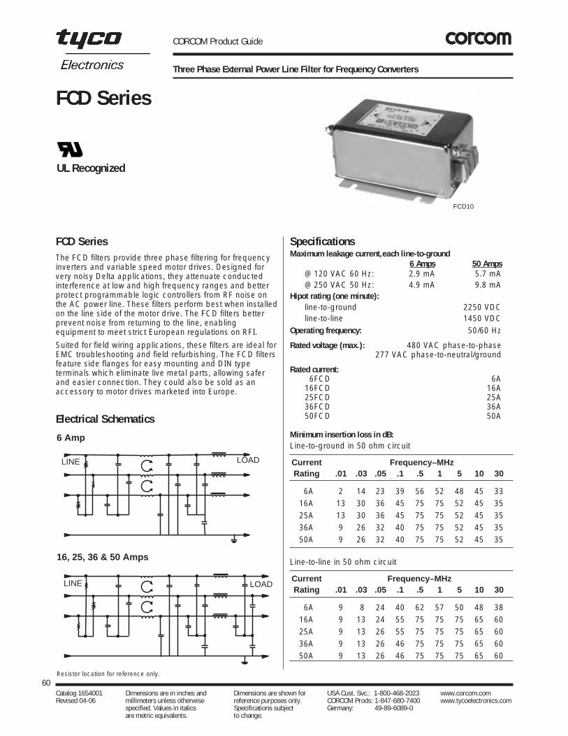
CORCOM Product Guide
Three Phase External Power Line Filter for Frequency Converters
The FCD filters provide three phase filtering for frequencyinverters and variable speed motor drives. Designed forvery noisy Delta applications, they attenuate conductedinterference at low and high frequency ranges and betterprotect programmable logic controllers from RF noise onthe AC power line. These filters perform best when installedon the line side of the motor drive. The FCD filters betterprevent noise from returning to the line, enablingequipment to meet strict European regulations on RFI.
Suited for field wiring applications, these filters are ideal forEMC troubleshooting and field refurbishing. The FCD filtersfeature side flanges for easy mounting and DIN typeterminals which eliminate live metal parts, allowing saferand easier connection. They could also be sold as anaccessory to motor drives marketed into Europe.
SpecificationsMaximum leakage current,each line-to-ground
6 Amps 50 Amps@ 120 VAC 60 Hz: 2.9 mA 5.7 mA@ 250 VAC 50 Hz: 4.9 mA 9.8 mA
Hipot rating (one minute):line-to-ground 2250 VDCline-to-line 1450 VDC
Operating frequency: 50/60 Hz
Rated voltage (max.): 480 VAC phase-to-phase277 VAC phase-to-neutral/ground
Rated current:06FCD 6A16FCD 16A25FCD 25A36FCD 36A50FCD 50A
Minimum insertion loss in dB:Line-to-ground in 50 ohm circuit
Current Frequency–MHzRating .01 .03 .05 .1 .5 1 5 10 30
6A 2 14 23 39 56 52 48 45 3316A 13 30 36 45 75 75 52 45 3525A 13 30 36 45 75 75 52 45 3536A 9 26 32 40 75 75 52 45 3550A 9 26 32 40 75 75 52 45 35
Line-to-line in 50 ohm circuit
Current Frequency–MHzRating .01 .03 .05 .1 .5 1 5 10 30
6A 9 8 24 40 62 57 50 48 3816A 9 13 24 55 75 75 75 65 6025A 9 13 26 55 75 75 75 65 6036A 9 13 26 46 75 75 75 65 6050A 9 13 26 46 75 75 75 65 60
60Catalog 1654001 Dimensions are in inches and Dimensions are shown for USA Cust. Svc.: 1-800-468-2023 www.corcom.com Revised 04-06 millimeters unless otherwise reference purposes only. CORCOM Prods: 1-847-680-7400 www.tycoelectronics.com
specified. Values in italics Specifications subject Germany: 49-89-6089-0 are metric equivalents. to change.
FCD Series
FCD Series
UL Recognized
Electrical Schematics
Resistor location for reference only.
6 Amp
16, 25, 36 & 50 Amps
LINE LOAD
LINE LOAD
FCD10

CORCOM Product Guide
Three Phase External Power Line Filter for Frequency Converters (Continued)
Case DimensionsA B C D E F
Part No. (max) (max) (max) (max)
6FCD10 6.00 4.30 2.30 3.74 5.15 2.756
152.4 109.2 58.4 95.0 128.3 70.0
16FCD10 7.20 5.48 2.55 4.92 5.94 2.756
182.9 139.2 64.8 124.97 150.9 70.0
25FCD10 9.69 6.30 2.55 5.71 8.46 4.528
246.1 160.0 64.8 145.0 215.0 115.01
36FCD10 9.69 6.30 2.55 5.71 8.46 4.528
246.1 160.0 64.8 145.0 215.0 115.01
50FCD10 10.5 6.30 2.54 5.71 8.46 4.528
266.7 160.0 64.52 145.0 215.0 115.01
61Catalog 1654001 Dimensions are in inches and Dimensions are shown for USA Cust. Svc.: 1-800-468-2023 www.corcom.com Revised 04-06 millimeters unless otherwise reference purposes only. CORCOM Prods: 1-847-680-7400 www.tycoelectronics.com
specified. Values in italics Specifications subject Germany: 49-89-6089-0 are metric equivalents. to change.
RFIPow
erLineFilters
FCD SeriesCase Style
Part Numbers
06FCD1016FCD1025FCD1036FCD1050FCD10
E
A
B D
Slots: .260 6.61 (4)
F
LABELLINE
LOAD
C
6FCD10, 16FCD10Phoenix contact VDFK4Accepts 10 AWG solid wire, 12 AWG stranded wireTorque Spec: 5.5 - 7.0 in.lb
25FCD10, 36FCD10Phoenix contact VDFK6Accepts 8 AWG solid wire, 10 AWG stranded wireTorque Spec: 13.5 - 16 in.lb
50FCD10Phoenix contact HDFK10-VPAccepts 6 AWG solid wire, 8 AWG stranded wireTorque Spec: 13.5 - 16 in.lb
Note: Terminals No. 8-32 (2)

CORCOM Product Guide
Differential Mode Filter for Fluorescent Lighting Applications
This filter is specifically designed to control the conducted emissions out of fluorescent lights, which are predominately differential mode (line-to-line). It isparticularly effective for use in industrial environments,where it may also be used to better protect susceptibleequipment from broadband conducted noise and inductiveswitching transients.
62Catalog 1654001 Dimensions are in inches and Dimensions are shown for USA Cust. Svc.: 1-800-468-2023 www.corcom.com Revised 04-06 millimeters unless otherwise reference purposes only. CORCOM Prods: 1-847-680-7400 www.tycoelectronics.com
specified. Values in italics Specifications subject Germany: 49-89-6089-0 are metric equivalents. to change.
FL Series
FL Series
UL Listed
3FL3
Electrical Schematic
LINE LOAD
SpecificationsHipot rating (one minute):
line-to-ground 1560 VACline-to-line 1560 VAC
Operating frequency: 50/60 Hz
Rated voltage: 125/280 VAC
Rated current: 3.9 AmpsTypical insertion loss in dB:Line-to-line in 50 ohm circuit
Current Frequency-MHzRating .15 .3 .6 1 4 10 203.9A 10 18 34 46 56 38 26

CORCOM Product Guide
Differential Mode Filter for Fluorescent Lighting Applications (Continued)
63Catalog 1654001 Dimensions are in inches and Dimensions are shown for USA Cust. Svc.: 1-800-468-2023 www.corcom.com Revised 04-06 millimeters unless otherwise reference purposes only. CORCOM Prods: 1-847-680-7400 www.tycoelectronics.com
specified. Values in italics Specifications subject Germany: 49-89-6089-0 are metric equivalents. to change.
RFIPow
erLineFilters
FL SeriesCase Style
A
E
D
B
C
0.44
0.4411.18
Strip0.5012.7(Typ)
18 AWG (4X)
7.0177.8
Min.(4 Wires)
Case DimensionsA B C D E
± .015Part No. (max) (max) (max) (max)± .38
3FL3 3.35 2.56 1.16 2.938 2.5785.09 65.02 29.5 74.63 65.3
Part Number
3FL3

CORCOM Product Guide
High Performance RFI Filters for Switching Power Supplies
The G series RFI filters are designed to provide excellentcommon-mode and differential-mode attenuation for mostdigital electronic equipment (particularly switching powersupplies) over the frequency range of 20kHz to 30MHz.
These filters are a size- and cost-effective solution forequipment that must meet the conducted emission limits ofEN55022 Level A requirements, as well as FCC Part 15J,Class B.
The EG models also meet the very low leakage currentrequirements for VDE portable equipment as well as (120volt) UL 544 non-patient medical equipment.
SpecificationsMaximum leakage current,each line-to-ground
EG Models VG Models@ 120 VAC 60 Hz: .30 mA 1.2 mA@ 250 VAC 50 Hz: .50 mA 2.0 mA
Hipot rating (one minute):line-to-ground 2250 VDCline-to-line 1450 VDC
Operating frequency: 50/60 Hz
Rated voltage (max.): 250 VAC
Rated current:6EG1/6VG1 6A10EG1/10VG1 10A
Minimum insertion loss in dB:Line-to-ground in 50 ohm circuit
64Catalog 1654001 Dimensions are in inches and Dimensions are shown for USA Cust. Svc.: 1-800-468-2023 www.corcom.com Revised 04-06 millimeters unless otherwise reference purposes only. CORCOM Prods: 1-847-680-7400 www.tycoelectronics.com
specified. Values in italics Specifications subject Germany: 49-89-6089-0 are metric equivalents. to change.
G Series
G Series
10EG1/10VG1
6EG1/6VG1
Electrical Schematics
6EG & 6VG Models
10EG & 10VG Models
Resistor location for reference only.
LINE LOAD
LINE LOAD
UL RecognizedCSA CertifiedVDE Approved
Current Frequency-MHzRating .01 .05 .07 .1 .15 .5 1 5 10 30
EG106A 6 19 23 25 29 48 44 43 40 4010A 8 10 15 18 42 64 65 65 60 60
VG106A 4 18 21 25 30 56 55 53 45 4510A 5 10 24 37 50 72 70 70 60 60
Line-to-line in 50 ohm circuit
Current Frequency-MHzRating .01 .05 .07 .1 .15 .5 1 5 10 30
EG106A 4 6 10 24 37 66 75 72 50 5010A 5 5 5 26 40 65 65 60 70 70
VG106A 4 7 7 26 39 67 75 68 55 5510A 5 5 7 26 39 65 60 60 70 70

CORCOM Product Guide
High Performance RFI Filters for Switching Power Supplies (Continued)
65Catalog 1654001 Dimensions are in inches and Dimensions are shown for USA Cust. Svc.: 1-800-468-2023 www.corcom.com Revised 04-06 millimeters unless otherwise reference purposes only. CORCOM Prods: 1-847-680-7400 www.tycoelectronics.com
specified. Values in italics Specifications subject Germany: 49-89-6089-0 are metric equivalents. to change.
RFIPow
erLineFilters
Case Style Case DimensionsA B C D E
± .015 Part No. (max) (max) (max) (max)± .38
6EG1/VG-1 3.56 2.15 1.56 2.938 3.3890.4 54.6 39.6 74.63 85.8
10EG1/VG1 4.69 2.27 1.8 4.063 4.47119.1 57.7 45.7 103.2 113.5
G Series
Typical dimensions:Terminals: .250 [6.35] (5) Holes: .07 [1.8] Dia.(4) Slot: .07 x .16 [1.8 x 4.1]Mounting holes: .188 [4.78] Dia. (2)
Part Numbers
06EG1 06VG110EG1 10VG1
A
B
CDE
EG1 & VG1

CORCOM Product Guide
RFI Power Line Filters for UL2601 Healthcare Equipment
The H series filters were developed specifically for healthcare applications. These products are suitable for uses inboth patient care equipment and non-patient careequipment. Their extremely low leakage current allowscompliance with UL2601 and CSA 22.2 health carespecifications.
See Appendix C for more information on UL544 health careapplications.
The H series features products with a variety of currentratings and case styles. Model 10EH4C additionallyincorporates a separate ground circuit inductor to isolateequipment chassis from power line ground at RFfrequencies.
For more information on UL2601, see Appendix C.
Note: When using the models with an IEC connector (e.g.6EH4), remember that the leakage current of thecompanion line cord, GA400, is more significant than thatof the filter – which may disqualify this line cord from use inpatient care applications.
*15EH4 - VDE rated at 10 amps, 250 VAC
SpecificationsMaximum leakage current,each line-to-ground
@ 120 VAC 60 Hz: 2µA@ 250 VAC 50 Hz: 5µA
Hipot rating (one minute):line-to-ground 2250 VDCline-to-line 1450 VDC
Operating frequency: 50/60 Hz
Rated voltage (max.): 250 VACMinimum insertion loss in dB:Line-to-ground in 50 ohm circuit
Current Frequency-MHzRating .15 .5 1 5 10 30
3A 18 27 30 30 27 186A 9 16 20 26 23 18
10A 7 13 15 17 16 1415A 5 9 11 12 11 9
Line CordLine Cord No. GA400:SVT type 71/2 foot, 3-conductor line cord to mate with allmodels except EH1. 50 micro amps maximum leakage @120 VAC, 60 Hz.
Case Style
66Catalog 1654001 Dimensions are in inches and Dimensions are shown for USA Cust. Svc.: 1-800-468-2023 www.corcom.com Revised 04-06 millimeters unless otherwise reference purposes only. CORCOM Prods: 1-847-680-7400 www.tycoelectronics.com
specified. Values in italics Specifications subject Germany: 49-89-6089-0 are metric equivalents. to change.
H Series
H Series
Electrical Schematic
Resistor location for reference only.
LINE LOAD
EH3
E D
A C
B
EH1
EH4/EH4C
EH5
EH9
EH8
UL RecognizedCSA CertifiedVDE Approved*
Typical dimensions:Wire leads: 4.0 [101.6] Min. 18 AWG Mounting holes: .132 [3.35] Dia. (2)
Typical dimensions:Wire leads: 4.0 [101.6] Min. 18 AWG Mounting holes: .132 [3.35] Dia. (2)

CORCOM Product Guide
RFI Power Line Filters for UL2601 Healthcare Equipment (Continued)
Case Styles Case Dimensions
A B C D E F± .015Part No. (max) (max) (max) (max) (ref)± .38
3EH1 2.25 1.82 0.66 2.125 2.53 —6EH1 57.2 46.1 16.7 53.98 64.210EH13EH3 .96 1.82 0.66 2.125 2.53 —6EH3 24.40 46.1 16.7 53.98 64.210EH3
6EH4 2.20 1.19 0.81 1.575 1.98 —55.9 30.2 20.6 40.01 50.3
6EH5 1.55 1.19 0.85 1.575 1.98 .29539.4 30.2 21.6 40.01 50.3 7.5
6EH8 1.56 1.19 0.81 1.575 1.98 .29539.7 30.2 20.6 40.01 50.3 7.5
6EH9 1.55 1.19 0.85 1.575 1.98 —39.4 30.2 21.6 40.01 50.3
10EH4 2.62 1.19 0.81 1.575 1.98 —66.5 30.2 20.6 40.01 50.3
10EH4C 2.62 1.19 0.81 1.575 1.98 —66.5 30.2 20.6 40.01 50.3
15EH4 2.62 1.19 0.81 1.575 1.98 —66.5 30.2 20.6 40.01 50.3
67Catalog 1654001 Dimensions are in inches and Dimensions are shown for USA Cust. Svc.: 1-800-468-2023 www.corcom.com Revised 04-06 millimeters unless otherwise reference purposes only. CORCOM Prods: 1-847-680-7400 www.tycoelectronics.com
specified. Values in italics Specifications subject Germany: 49-89-6089-0 are metric equivalents. to change.
RFIPow
erLineFilters
H Series
EH1
EH4 & EH4C
EH9
EH5
EH8
Part Numbers
3EH1 06EH83EH3 06EH96EH1 10EH16EH3 10EH36EH4 10EH46EH5 10EH4C
15EH4*Line Cord No. GA400Insulating Boot No. (EH4, EH4C) FA601*UL, CSA — 15A; VDE — 10A
Typical dimensions:Terminals: .250 [6.35] (5) Holes: .07 [1.8] Dia.(4) Slot: .07 x .16 [1.8 x 4.1]Mounting holes: .188 [4.78] Dia. (2)
Typical dimensions:Terminals: .250 [6.35] (3) Holes: .07 [1.8] Dia.(2) Slot: .07 x .16 [1.8 x 4.1]Mounting holes: .132 [3.35] Dia. (2)
Typical dimensions:Wire leads: 4.0 [101.6] Min. 18 AWG Mounting holes: .132 [3.35] Dia. (2)
E B
A
D
C
A
C
BD
E
DE A
C
B
.6516.5
Max.
C
A
F
F
B
Bro
wn
Gre
en/Y
ello
w
Blu
e
D
E
Note 1: EH4, EH4C and EH8 allow front or back mounting.Note 2: EH5 and EH9 allow back mounting only.
.1403.56
.0621.58
.82020.8
R
Dia. (2)1.20030.48
1.57540.01
.1403.56
.2345.94
.90022.9
R
Dia. (2)1.20030.48
1.57540.01
Recommended Panel Cutouts
Panel Cutout (back mount)Panel Cutout (front mount)
Tolerance ±.005 [0.13]Tolerance ±.005 [0.13]
Blue
Green/Yellow
BrownB
C
F
F
D E
A

CORCOM Product Guide
Highest Performance RFI Filters for Medical Equipment
The HQ series power line filters provide the highestavailable common-mode and differential-mode attenuationto RFI noise in the frequency range from 10kHz to 30MHz,for IEC 60601 and UL2601 patient-connected equipment,as well as all other electronic equipment that cannottolerate any leakage current.
They are a size- and more cost-effective solution to theproblem of meeting both medical leakage current limits andconducted emissions limits in equipment with high noisesources (such as switching power supplies). HQ seriesfilters can help meet the following Conducted Emissionsstandards:
• European Normalized Standards based on EN55022, Level B
• FCC Part 15, Computing Devices, Class B.
• FCC Part 18, ISM Equipment, Industrial and Consumer.
For more information on UL2601, see Appendix C.
SpecificationsMaximum leakage current,each line-to-ground
@ 120 VAC 60 Hz: 2µA@ 250 VAC 50 Hz: 5µA
Hipot rating (one minute):line-to-ground 2250 VDCline-to-line 1450 VDC
Operating frequency: 50/60 Hz
Rated voltage (max.): 250 VAC
Rated current:3EHQ 3A6EHQ 6A
Maximum rated current peaks:3EHQ 10A6EHQ 18A
Minimum insertion loss in dB:Line-to-ground in 50 ohm circuit
Current Frequency–MHzRating .01 .02 .05 .15 .5 1 2 5 7 10 20 30
3A 19 24 32 44 44 40 38 28 25 22 13 106A 24 29 39 42 28 35 36 30 30 24 16 15
Line-to-line in 50 ohm circuit
Current Frequency–MHzRating .01 .02 .05 .15 .5 1 2 5 7 10 20 30
3A 1 18 43 68 75 75 72 70 66 65 60 606A 6 10 43 70 75 75 75 65 50 55 50 40
Line CordLine Cord No. GA400:71/2 foot, 3-conductor line cord to mate with Q8 models.
68Catalog 1654001 Dimensions are in inches and Dimensions are shown for USA Cust. Svc.: 1-800-468-2023 www.corcom.com Revised 04-06 millimeters unless otherwise reference purposes only. CORCOM Prods: 1-847-680-7400 www.tycoelectronics.com
specified. Values in italics Specifications subject Germany: 49-89-6089-0 are metric equivalents. to change.
HQ Series
HQ Series
3EHQ8
HQ36EHQ8
HQ1
Electrical Schematics
3 Amp Models
6 Amp Models
Resistor location for reference only.
LINE LOAD
LINE LOAD
UL RecognizedCSA CertifiedVDE Approved
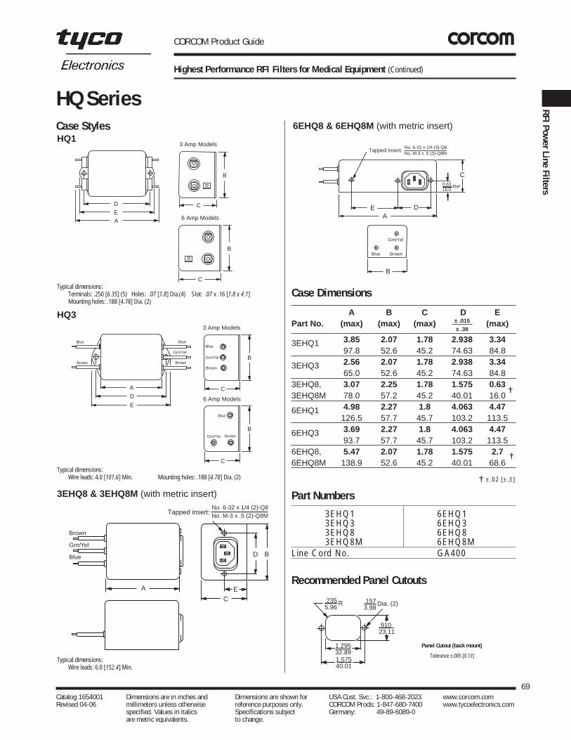
CORCOM Product Guide
Highest Performance RFI Filters for Medical Equipment (Continued)
Case Styles
Case Dimensions
A B C D E± .015Part No. (max) (max) (max) (max)± .38
3EHQ1 3.85 2.07 1.78 2.938 3.3497.8 52.6 45.2 74.63 84.8
3EHQ3 2.56 2.07 1.78 2.938 3.3465.0 52.6 45.2 74.63 84.8
3EHQ8, 3.07 2.25 1.78 1.575 0.633EHQ8M 78.0 57.2 45.2 40.01 16.0
6EHQ1 4.98 2.27 1.8 4.063 4.47126.5 57.7 45.7 103.2 113.5
6EHQ3 3.69 2.27 1.8 4.063 4.4793.7 57.7 45.7 103.2 113.5
6EHQ8, 5.47 2.07 1.78 1.575 2.76EHQ8M 138.9 52.6 45.2 40.01 68.6
69Catalog 1654001 Dimensions are in inches and Dimensions are shown for USA Cust. Svc.: 1-800-468-2023 www.corcom.com Revised 04-06 millimeters unless otherwise reference purposes only. CORCOM Prods: 1-847-680-7400 www.tycoelectronics.com
specified. Values in italics Specifications subject Germany: 49-89-6089-0 are metric equivalents. to change.
RFIPow
erLineFilters
HQ Series
Part Numbers
3EHQ1 6EHQ13EHQ3 6EHQ33EHQ8 6EHQ83EHQ8M 6EHQ8M
Line Cord No. GA400
HQ1
HQ3
3EHQ8 & 3EHQ8M (with metric insert)
6EHQ8 & 6EHQ8M (with metric insert)
D
E
A
C
B
C
B
3 Amp Models
6 Amp Models
Typical dimensions:Terminals: .250 [6.35] (5) Holes: .07 [1.8] Dia.(4) Slot: .07 x .16 [1.8 x 4.1]Mounting holes: .188 [4.78] Dia. (2)
Typical dimensions:Wire leads: 4.0 [101.6] Min. Mounting holes: .188 [4.78] Dia. (2)
Typical dimensions:Wire leads: 6.0 [152.4] Min.
A
D
E
Brown
Blue
Brown
Blue
Grn/Yel
C
B
C
B
Blue
Grn/Yel Brown
Blue
Grn/Yel
Brown
3 Amp Models
6 Amp Models
A
Tapped insert:
D B
E
C
No. 6-32 x 1/4 (2)-Q8No. M-3 x .5 (2)-Q8M
Brown
Grn/Yel
Blue
Recommended Panel Cutouts
Panel Cutout (back mount)
Tolerance ±.005 [0.13]
.2355.96
1.57540.01
.1573.98
.91023.11
Dia. (2)
1.29532.89
R
EA
D
C
B
Grn/Yel
Blue Brown
Tapped insert:No. 6-32 x 1/4 (3)-Q8No. M-3 x .5 (3)-Q8M
0.6316.0
Ref
†
†
† ±.02 [±.5]

CORCOM Product Guide
High Performance RFI Power Line Filters for Medical Equipment
The HT series power line filters provide superior common-mode and premium differential-mode attenuation to RFInoise on the frequency range from 10kHz to 30MHz, forIEC 60601 and UL2601 patient-connected equipment, aswell as all other electronic equipment that cannot tolerateleakage current.
They are a size- and cost-effective solution to the problemof meeting both medical leakage current limits andconducted emissions limits in equipment with high noisesources (such as switching power supplies). HT seriesfilters can meet the following Conducted Emissionsstandards:
• European Normalized Standards based on EN55022, Level A (in many cases, Level B also).
• FCC Part 15, Computing Devices, Class B.
• FCC Part 18, ISM Equipment, Industrial andConsumer.
Note: When using the models with an IEC connector, remember that the leakage current of the companion linecord, GA400, is more significant than that of the filter - which may disqualify this line cord from use in patient careapplications. For more information on UL2601, see Appendix C.
SpecificationsMaximum leakage current,each line-to-ground
@ 120 VAC 60 Hz: 2µA@ 250 VAC 50 Hz: 5µA
Hipot rating (one minute):line-to-ground 1500 VACline-to-line 1450 VDC
Operating frequency: 50/60 Hz
Rated voltage (max.): 250 VACMinimum insertion loss in dB:
Line-to-ground in 50 ohm circuit
Current Frequency–MHzRating .01 .02 .05 .08 .15 .5 1 2 5 10 20 30
6A 16 23 32 41 46 41 33 26 15 9 6 210A 9 15 24 30 36 42 34 22 11 12 8 815A 4 9 18 22 27 41 34 22 12 12 5 2
Line-to-line in 50 ohm circuit
Current Frequency–MHzRating .01 .02 .05 .08 .15 .5 1 2 5 10 20 30
6A 4 1 14 45 51 70 70 65 55 47 37 3710A 7 8 17 32 52 70 70 70 65 55 40 3515A 12 16 15 10 51 70 70 70 70 70 65 55
70Catalog 1654001 Dimensions are in inches and Dimensions are shown for USA Cust. Svc.: 1-800-468-2023 www.corcom.com Revised 04-06 millimeters unless otherwise reference purposes only. CORCOM Prods: 1-847-680-7400 www.tycoelectronics.com
specified. Values in italics Specifications subject Germany: 49-89-6089-0 are metric equivalents. to change.
HT Series
HT Series
Electrical Schematics6 Amp
10 Amp
LINE LOAD
LINE LOAD
15 Amp
LINE LOAD
HT1
HT7
HT6
HT3
UL RecognizedCSA CertifiedVDE Approved
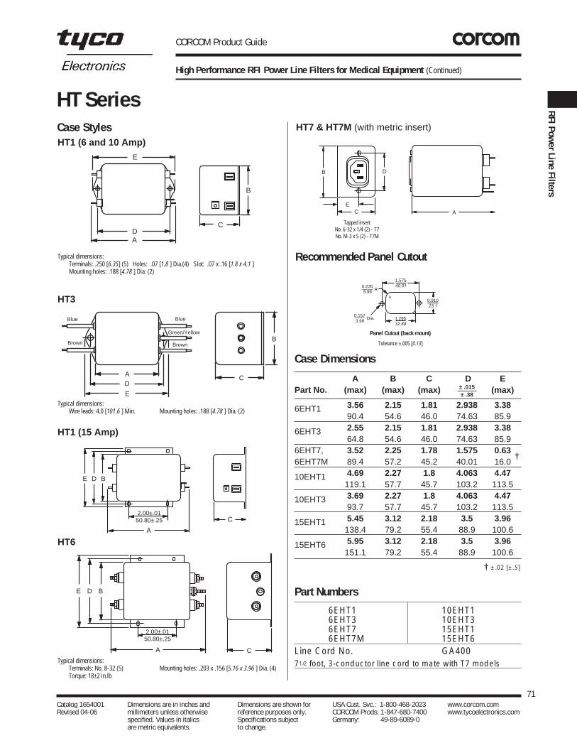
CORCOM Product Guide
High Performance RFI Power Line Filters for Medical Equipment (Continued)
Case Styles
Recommended Panel Cutout
Case Dimensions
A B C D E± .015Part No. (max) (max) (max) (max)± .38
6EHT1 3.56 2.15 1.81 2.938 3.3890.4 54.6 46.0 74.63 85.9
6EHT3 2.55 2.15 1.81 2.938 3.3864.8 54.6 46.0 74.63 85.9
6EHT7, 3.52 2.25 1.78 1.575 0.636EHT7M 89.4 57.2 45.2 40.01 16.0
10EHT1 4.69 2.27 1.8 4.063 4.47119.1 57.7 45.7 103.2 113.5
10EHT3 3.69 2.27 1.8 4.063 4.4793.7 57.7 45.7 103.2 113.5
15EHT1 5.45 3.12 2.18 3.5 3.96138.4 79.2 55.4 88.9 100.6
15EHT6 5.95 3.12 2.18 3.5 3.96151.1 79.2 55.4 88.9 100.6
71Catalog 1654001 Dimensions are in inches and Dimensions are shown for USA Cust. Svc.: 1-800-468-2023 www.corcom.com Revised 04-06 millimeters unless otherwise reference purposes only. CORCOM Prods: 1-847-680-7400 www.tycoelectronics.com
specified. Values in italics Specifications subject Germany: 49-89-6089-0 are metric equivalents. to change.
RFIPow
erLineFilters
HT Series
HT1 (6 and 10 Amp)
HT3
HT1 (15 Amp)
HT6
B
CDA
E
Typical dimensions:Terminals: .250 [6.35] (5) Holes: .07 [1.8 ] Dia.(4) Slot: .07 x .16 [1.8 x 4.1 ]Mounting holes: .188 [4.78 ] Dia. (2)
Typical dimensions:Wire leads: 4.0 [101.6 ] Min. Mounting holes: .188 [4.78 ] Dia. (2)
Typical dimensions:Terminals: No. 8-32 (5) Mounting holes: .203 x .156 [5.16 x 3.96 ] Dia. (4)Torque: 18±2 in.lb
Brown
Green/Yellow
BlueBlue
Brown
AD
E
C
B
E D B
A
2.00±.0150.80±.25 C
E D B
C
2.00±.0150.80±.25
A
†
† ±.02 [±.5]
Part Numbers
6EHT1 10EHT16EHT3 10EHT36EHT7 15EHT16EHT7M 15EHT6
Line Cord No. GA40071/2 foot, 3-conductor line cord to mate with T7 models
HT7 & HT7M (with metric insert)
B D
EC A
1.57540.01
0.910 23.1
0.157 3.98
Dia.
0.235 5.96
R
1.29532.89
B D
EC A
1.57540.01
0.910 23.1
0.157 3.98
Dia.
0.235 5.96
R
1.29532.89
Panel Cutout (back mount)
Tolerance ±.005 [0.13]
Tapped insertNo. 6-32 x 1/4 (2) - T7No. M-3 x 5 (2) - T7M

CORCOM Product Guide
High Performance Power Line Filter for Medical Applications
The HZ series provides good performance for filtering inmedical applications. The leakage current for this filter isextremely low due to the absence of the line-to-groundcapacitors. The high inductance value allows goodperformance for both differential and common mode noisein a compact package.
The filter is compact and available with a 3 amp currentrating. Moderately priced, this filter is a good alternative for medical applications where additional protection isneeded.
For more information on UL544, see Appendix C.
SpecificationsMaximum leakage current,each line-to-ground
@ 120 VAC 60 Hz: 2µA@ 250 VAC 50 Hz: 5µA
Hipot rating (one minute):line-to-ground 2250 VDCline-to-line 1450 VDC
Operating frequency: 50/60 Hz
Rated voltage (max.): 250 VAC
Rated current:3EHZ 3A
Minimum insertion loss in dB:
Line-to-ground in 50 ohm circuit
Current Frequency-MHzRating .01 .05 .15 .5 1 5 10 30
3EHZ1 10 24 34 34 35 15 10 5
Line-to-line in 50 ohm circuit
Current Frequency-MHzRating .03 .05 .15 .5 1 5 10 30
3EHZ1 10 25 54 70 70 65 55 55
72Catalog 1654001 Dimensions are in inches and Dimensions are shown for USA Cust. Svc.: 1-800-468-2023 www.corcom.com Revised 04-06 millimeters unless otherwise reference purposes only. CORCOM Prods: 1-847-680-7400 www.tycoelectronics.com
specified. Values in italics Specifications subject Germany: 49-89-6089-0 are metric equivalents. to change.
HZ Series
HZ Series
Electrical Schematic
3EHZ1
UL RecognizedCSA CertifiedVDE Approved
LINE LOAD
Resistor location for reference only.

CORCOM Product Guide
High Performance Power Line Filter for Medical Applications (Continued)
Case StyleHZ1
73Catalog 1654001 Dimensions are in inches and Dimensions are shown for USA Cust. Svc.: 1-800-468-2023 www.corcom.com Revised 04-06 millimeters unless otherwise reference purposes only. CORCOM Prods: 1-847-680-7400 www.tycoelectronics.com
specified. Values in italics Specifications subject Germany: 49-89-6089-0 are metric equivalents. to change.
RFIPow
erLineFilters
HZ SeriesCase Dimensions
A B C D E± .015Part No. (max) (max) (max) (max)± .38
3.54 2.08 1.31 2.938 3.353EHZ1 89.9 52.8 33.3 74.63 85.1
Part Number
3EHZ1
A
B
CDE
Typical dimensions:Terminals: .250 [6.35] (5) Holes: .07 [1.8] Dia.(4)Mounting Holes: .188 [4.78] Dia. (2) Slot: .07 x .16 [1.8 x 4.1]
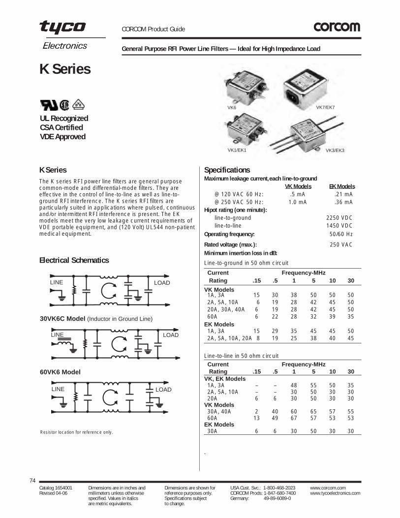
CORCOM Product Guide
General Purpose RFI Power Line Filters — Ideal for High Impedance Load
The K series RFI power line filters are general purposecommon-mode and differential-mode filters. They areeffective in the control of line-to-line as well as line-to-ground RFI interference. The K series RFI filters areparticularly suited in applications where pulsed, continuousand/or intermittent RFI interference is present. The EKmodels meet the very low leakage current requirements ofVDE portable equipment, and (120 Volt) UL544 non-patientmedical equipment.
SpecificationsMaximum leakage current,each line-to-ground
VK Models EK Models@ 120 VAC 60 Hz: .5 mA .21 mA@ 250 VAC 50 Hz: 1.0 mA .36 mA
Hipot rating (one minute):line-to-ground 2250 VDCline-to-line 1450 VDC
Operating frequency: 50/60 Hz
Rated voltage (max.): 250 VACMinimum insertion loss in dB:
Line-to-ground in 50 ohm circuit
Current Frequency-MHzRating .15 .5 1 5 10 30
VK Models1A, 3A 15 30 38 50 50 502A, 5A, 10A 6 19 28 42 45 5020A, 30A, 40A 6 19 28 42 45 5060A 6 22 28 32 39 35
EK Models1A, 3A 15 29 35 45 45 502A, 5A, 10A, 20A 8 19 25 38 40 45
Line-to-line in 50 ohm circuitCurrent Frequency-MHzRating .15 .5 1 5 10 30
VK, EK Models1A, 3A – – 48 55 50 352A, 5A, 10A – – 30 50 30 3020A 6 6 30 50 30 30
VK Models30A, 40A 2 40 60 65 57 5560A 13 49 67 57 53 53
EK Models30A 6 6 30 50 30 30
.
74Catalog 1654001 Dimensions are in inches and Dimensions are shown for USA Cust. Svc.: 1-800-468-2023 www.corcom.com Revised 04-06 millimeters unless otherwise reference purposes only. CORCOM Prods: 1-847-680-7400 www.tycoelectronics.com
specified. Values in italics Specifications subject Germany: 49-89-6089-0 are metric equivalents. to change.
K Series
K Series
UL RecognizedCSA CertifiedVDE Approved
Electrical Schematics
Resistor location for reference only.
VK1/EK1
VK7/EK7VK6
VK3/EK3
LINE LOAD
LINE LOAD
30VK6C Model (Inductor in Ground Line)
LINE LOAD
60VK6 Model

Case StylesK1
K3
CORCOM Product Guide
General Purpose RFI Power Line Filters — Ideal for High Impedance Load (Continued)
75Catalog 1654001 Dimensions are in inches and Dimensions are shown for USA Cust. Svc.: 1-800-468-2023 www.corcom.com Revised 04-06 millimeters unless otherwise reference purposes only. CORCOM Prods: 1-847-680-7400 www.tycoelectronics.com
specified. Values in italics Specifications subject Germany: 49-89-6089-0 are metric equivalents. to change.
RFIPow
erLineFilters
K Series
E D B
A C
Typical dimensions:Terminals: .250 [6.35] (5) Holes: .07 [1.8] Dia.(4)Slot: .07 x .16 [1.8 x 4.1] Mounting holes: .188 [4.78] Dia. (2)
Typical dimensions:Wire leads: 4.0 [101.6] Min. Mounting holes: .188 [4.78] Dia. (2)
Typical dimensions:Mounting holes: .188 [4.78] Dia. (2) Torque 18±2 in.lb
E D B
A C
Blue Blue
Brown
Green/Yellow
Brown
10VK6
E D B
Terminals:No. 8-32 (5)
A C
20EK1/20VK1
E D B
A C
Case StylesK1
K3

CORCOM Product Guide
General Purpose RFI Power Line Filters — Ideal for High Impedance Load (Continued)
76Catalog 1654001 Dimensions are in inches and Dimensions are shown for USA Cust. Svc.: 1-800-468-2023 www.corcom.com Revised 04-06 millimeters unless otherwise reference purposes only. CORCOM Prods: 1-847-680-7400 www.tycoelectronics.com
specified. Values in italics Specifications subject Germany: 49-89-6089-0 are metric equivalents. to change.
K Series
20VK7 (with metric insert)
K7 & K7M
A
Insert (4): 6-32
D B
C
E
E
.669 ± .01016.99 ± .25.512 ± .01013.00 ± .25
2.65 ± .01667.31±4.06
.0621.60
.1574.0
Dia. R
1.4637.1
1.145 29.1
D
Typical dimensions:Terminals: .250 [6.35] (3)Holes: .07 [1.8] Dia.(2)Slot: .07 x .16 [1.8 x 4.1]
A
Tapped insertNo. 6-32 x 1/4 (2) - K7No. M-3 x .5 (2) - K7M
D
E
C
B
Tolerance ±.005 [0.13]
Panel Cutout (back mount)
.2355.96
1.57540.01
.1573.98
.91023.1
Dia.
1.29532.89
R
20VK6
30VK6 & 30VK6C, 40VK6 & 40VK6C
E D B
Terminals:No. 8-32 (5)
A C
Typical dimensions:Terminals: No. 8-32 (5) Torque: 18 ± 2 in. lb. Slots: .250 [6.35] x .156 [3.96] (4) Mounting holes: .188 [4.78] Dia. (2)
EDB
2.0050.8
AC
Terminal on 30VK6C and 40VK6C only
60VK6
E BD
Terminals #1/4-20 (5) 2.00
50.8
A
.250 x .156( 4 Slots )
C
Case Styles

CORCOM Product Guide
General Purpose RFI Power Line Filters — Ideal for High Impedance Load (Continued)
Case Styles
Case DimensionsA B C D E
± .015Part No. (max) (max) (max) (max)± .38
1VK1, 1EK1, 3.1 2.07 0.91 2.375 2.812VK1, 2EK1 78.7 52.6 23.1 60.33 71.41VK3, 1EK3, 1.81 2.07 0.91 2.375 2.812VK3, 2EK3 46.0 52.6 23.1 60.33 71.43VK1, 3EK1, 3.10 2.07 1.16 2.375 2.815VK1, 5EK1 78.7 52.6 29.5 60.33 71.43VK3, 3EK3, 1.81 2.07 1.16 2.375 2.815VK3, 5EK3 46.0 52.6 29.5 60.33 71.43VK7, 3VK7M, 3.21 2.25 1.28 1.575 0.633EK7, 3EK7M 81.5 57.2 32.5 40.01 16.05VK7, 5VK7M, 3.21 2.25 1.28 1.575 0.635EK7, 5EK7M 81.5 57.2 32.5 40.01 16.010VK1, 3.35 2.07 1.16 2.375 2.8110EK1 85.1 52.6 29.5 60.33 71.410VK3, 2.07 2.07 1.16 2.375 2.8110EK3 52.6 52.6 29.5 60.33 71.4
10VK6 3.46 2.07 1.16 2.375 2.8187.9 52.6 29.5 60.33 71.4
10VK7, 10VK7M, 3.71 2.25 1.28 1.575 0.6310EK7, 10EK7M 94.2 57.2 32.5 40.01 16.020VK1, 3.35 2.56 1.53 2.938 3.3520EK1 85.1 65.0 38.9 74.63 85.1
20VK6 3.46 2.56 1.53 2.938 3.3587.9 65.0 38.9 74.63 85.1
20VK7 3.8 2.28 1.78 1.575 .846 90.4 54.6 39.6 74.63 85.8
30VK6, 5.34 3.38 1.53 3.75 4.2030VK6C 135.6 85.9 38.9 95.25 106.740VK6, 5.34 3.38 1.53 3.75 4.2040VK6C 135.6 85.9 38.9 95.25 106.7
60VK6 6.189 3.344 1.50 3.75 4.136157.2 84.94 38.1 95.25 105.05
77Catalog 1654001 Dimensions are in inches and Dimensions are shown for USA Cust. Svc.: 1-800-468-2023 www.corcom.com Revised 04-06 millimeters unless otherwise reference purposes only. CORCOM Prods: 1-847-680-7400 www.tycoelectronics.com
specified. Values in italics Specifications subject Germany: 49-89-6089-0 are metric equivalents. to change.
RFIPow
erLineFilters
K Series
Part Numbers
1VK11VK32VK12VK33VK13VK33VK73VK7M5VK15VK35VK75VK7M
10VK110VK310VK610VK710VK7M20VK120VK620VK730VK630VK6C40VK640VK6C60VK6
1EK11EK32EK12EK33EK13EK33EK73EK7M5EK15EK35EK7M
10EK110EK3 10EK710EK7M20EK1
Line Cord No. GA400
20VK6
20VK7
VK1/EK1
† ±.02 [±0.5]
‡ ±.01 [±.0.25]
†
†
†
‡

CORCOM Product Guide
Multi-purpose Medical Filter for Power Line Noise Protectionwith Limited Leakage Current
The MV series answers the need for a medical filter to helpequipment comply with increasing noise sources inmedical applications while still meeting leakage currentrequirements of UL2601.
Less strict than previous UL medical standards, UL2601limits leakage current for patient care equipment. Due tothe increased need for higher performance filtering, UL hasallowed more leakage current than in previous standards.
The MV takes advantage of this to offer improved line-to-ground performance in a moderately priced filter. Higherline-to-line performance is achieved through its additionaldifferential mode rod inductors. Overall, the filter providesa good solution to emission and immunity problems, at amoderate cost, in a reasonable package size.
SpecificationsMaximum leakage current,each line-to-ground
@ 120 VAC 60 Hz: .07 mA@ 250 VAC 50 Hz: .13 mA
Hipot rating (one minute):line-to-ground 2250 VDCline-to-line 1450 VDC
Operating frequency: 50/60 Hz
Rated voltage (max.): 250 VAC
Rated current:3MV 3A6MV 6A10MV 10A20MV 20A
Minimum insertion loss in dB:Line-to-ground in 50 ohm circuitCurrent Frequency-MHzRating .15 .5 1 2 5 10 20 303A 14 19 20 30 46 40 34 31 6A 19 27 30 38 50 40 35 35
10A 15 25 26 34 46 50 44 4220A 18 30 34 34 46 40 36 20
Line-to-line in 50 ohm circuit
Current Frequency-MHzRating .15 .5 1 2 5 10 20 30
3A 33 65 65 65 65 60 53 506A 40 65 65 65 65 60 57 55
10A 33 65 65 65 65 65 55 5520A 25 65 65 65 65 60 57 45
78Catalog 1654001 Dimensions are in inches and Dimensions are shown for USA Cust. Svc.: 1-800-468-2023 www.corcom.com Revised 04-06 millimeters unless otherwise reference purposes only. CORCOM Prods: 1-847-680-7400 www.tycoelectronics.com
specified. Values in italics Specifications subject Germany: 49-89-6089-0 are metric equivalents. to change.
MV Series
MV Series
Electrical Schematic
LINE LOAD
Resistor location for reference only.
3A, 6A, 10A
3A, 6A, 10A, 20A
UL RecognizedCSA CertifiedVDE Approved

CORCOM Product Guide
Multi-purpose Medical Filter for Power Line Noise Protectionwith Limited Leakage Current (Continued)
Case Dimensions
A B C D E± .015Part No. (max) (max) (max) (max)± .38
3MV1 3.36 1.82 1.28 2.375 2.7885.3 46.2 32.5 60.33 70.6
6MV1 3.86 2.08 1.53 2.938 3.3498.0 52.8 38.9 74.63 84.8
10MV1 3.86 2.08 1.53 2.938 3.3498.0 52.8 38.9 74.63 84.8
20MV1 5.23 3.38 1.53 3.75 4.20132.8 85.9 38.9 95.25 106.7
79Catalog 1654001 Dimensions are in inches and Dimensions are shown for USA Cust. Svc.: 1-800-468-2023 www.corcom.com Revised 04-06 millimeters unless otherwise reference purposes only. CORCOM Prods: 1-847-680-7400 www.tycoelectronics.com
specified. Values in italics Specifications subject Germany: 49-89-6089-0 are metric equivalents. to change.
RFIPow
erLineFilters
MV Series
D
E
A
C
B
DE
A C
B
Slots:.250 x .1566.35 x 3.96
(4)
2.0050.8
3/6/10 MV1
20A
Part Numbers
03MV106MV110MV120MV1
Case Styles
Typical dimensions:Terminals: .250 [6.35] (5) Holes: .07 [1.8] Dia.(4)Slot: .07 x .16 [1.8 x 4.1] Mounting holes: .188 [4.78] Dia. (2)
Typical dimensions:Terminals: .250 [6.35] (5) Holes: .07 [1.8] Dia.(4)Slot: .07 x .16 [1.8 x 4.1]
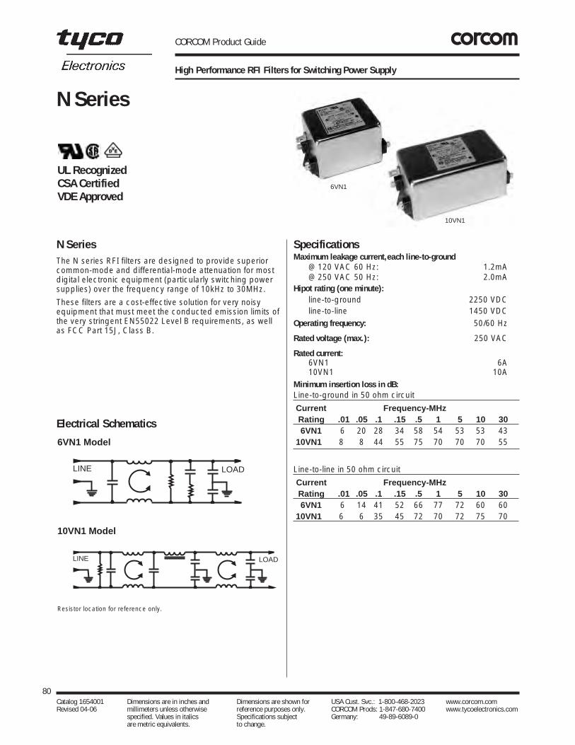
CORCOM Product Guide
High Performance RFI Filters for Switching Power Supply
The N series RFI filters are designed to provide superiorcommon-mode and differential-mode attenuation for mostdigital electronic equipment (particularly switching powersupplies) over the frequency range of 10kHz to 30MHz.
These filters are a cost-effective solution for very noisyequipment that must meet the conducted emission limits ofthe very stringent EN55022 Level B requirements, as wellas FCC Part 15J, Class B.
SpecificationsMaximum leakage current,each line-to-ground
@ 120 VAC 60 Hz: 1.2mA@ 250 VAC 50 Hz: 2.0mA
Hipot rating (one minute):line-to-ground 2250 VDCline-to-line 1450 VDC
Operating frequency: 50/60 Hz
Rated voltage (max.): 250 VAC
Rated current:6VN1 6A10VN1 10A
Minimum insertion loss in dB:Line-to-ground in 50 ohm circuit
Current Frequency-MHzRating .01 .05 .1 .15 .5 1 5 10 306VN1 6 20 28 34 58 54 53 53 43
10VN1 8 8 44 55 75 70 70 70 55
Line-to-line in 50 ohm circuit
Current Frequency-MHzRating .01 .05 .1 .15 .5 1 5 10 306VN1 6 14 41 52 66 77 72 60 60
10VN1 6 6 35 45 72 70 72 75 70
80Catalog 1654001 Dimensions are in inches and Dimensions are shown for USA Cust. Svc.: 1-800-468-2023 www.corcom.com Revised 04-06 millimeters unless otherwise reference purposes only. CORCOM Prods: 1-847-680-7400 www.tycoelectronics.com
specified. Values in italics Specifications subject Germany: 49-89-6089-0 are metric equivalents. to change.
N Series
N Series
Electrical Schematics
Resistor location for reference only.
LINE LOAD
LINE LOAD
6VN1
10VN1
6VN1 Model
10VN1 Model
UL RecognizedCSA CertifiedVDE Approved

CORCOM Product Guide
High Performance RFI Filters for Switching Power Supply (Continued)
Case Style Case DimensionsA B C D E
± .015Part No. (max) (max) (max) (max)± .38
6VN1 3.56 2.15 1.81 2.938 3.3890.4 54.6 45.9 74.63 85.8
10VN1 4.69 2.27 1.8 4.063 4.47119.1 57.7 45.7 103.2 113.5
81Catalog 1654001 Dimensions are in inches and Dimensions are shown for USA Cust. Svc.: 1-800-468-2023 www.corcom.com Revised 04-06 millimeters unless otherwise reference purposes only. CORCOM Prods: 1-847-680-7400 www.tycoelectronics.com
specified. Values in italics Specifications subject Germany: 49-89-6089-0 are metric equivalents. to change.
RFIPow
erLineFilters
N Series
Part Numbers
6VN1 10VN1
A
B
CDE
6VN1 & 10VN1
Typical dimensions:Terminals: .250 [6.35] (5) Holes: .07 [1.8] Dia.(4)Mounting Holes: .188 [4.78] Dia. (2) Slot: .07 x .16 [1.8 x 4.1]

CORCOM Product Guide
Highest Performance RFI Filters for Switching Power Supply Emissions down to 10 kHz
This series of RFI power line filters has been developedspecifically for switching power supplies and is designed tobe all the power line filtering needed to control conductedemissions all the way down to 10kHz. High attenuation isprovided for both common mode and differential modeinterference throughout the frequency range with nodegradation of performance due to the large peak currentsdrawn by switching power supplies.
These filters are an ideal choice for applications that mustmeet emission limits below 150kHz, as well as themandated limits above 150kHz. In most cases they willbring such equipment into compliance with the B-levellimits of CISPR 22. They are also well suited for bringingISM equipment (such as ultrasonic cleaners) intocompliance with the limits of FCC Part 18, from 10kHz to30MHz.
The EQ models meet the very low leakage currentrequirements VDE portable equipment, and (120 Volt)UL544 non-patient medical equipment. The VQ modelsoffer higher common mode performance at the expense ofhigher leakage current, but still meet the leakage currentlimits of UL, CSA, and VDE non-portable equipment.
SpecificationsMaximum leakage current,each line-to-ground
VQ Models EQ Models@ 120 VAC 60 Hz (3A, 20A): .73 mA .22 mA@ 120 VAC 60 Hz (6A): — .29 mA@ 250 VAC 50 Hz (3A, 20A): 1.27 mA .38 mA@ 250 VAC 50 Hz (6A): — .51 mA
Hipot rating (one minute):line-to-ground 2250 VDCline-to-line 1450 VDC
Operating frequency: 50/60 Hz
Rated voltage (max.): 250 VAC
Rated current:3VQ/3EQ 3A6EQ 6A20EQ1/20VQ1 20A
Minimum insertion loss in dB:Line-to-ground in 50 ohm circuit
Current Frequency–MHzRating .01 .02 .05 .15 .5 1 5 10 30
3VQ 22 27 37 50 55 55 55 50 553EQ 22 27 36 47 47 43 45 45 456EQ 26 31 20 68 72 72 65 65 65
20EQ1 6 10 8 39 60 65 65 65 5520VQ1 6 3 17 52 65 70 70 70 70
Line-to-line in 50 ohm circuit
Current Frequency–MHzRating .01 .02 .05 .15 .5 1 5 10 30
3VQ 1 17 42 65 75 75 60 65 653EQ 1 17 42 65 75 75 65 65 606EQ 6 10 43 70 75 75 65 55 55
20EQ1 15 20 20 46 65 70 65 60 6020VQ1 15 20 20 46 65 70 65 60 60
Line CordLine Cord No. GA400: 7 1/2 foot, 3-conductor line cord to mate with Q8 models.
82Catalog 1654001 Dimensions are in inches and Dimensions are shown for USA Cust. Svc.: 1-800-468-2023 www.corcom.com Revised 04-06 millimeters unless otherwise reference purposes only. CORCOM Prods: 1-847-680-7400 www.tycoelectronics.com
specified. Values in italics Specifications subject Germany: 49-89-6089-0 are metric equivalents. to change.
Q Series
Q Series
Electrical Schematics
LINE LOAD
LINE LOAD
Resistor location for reference only.
3EQ & 3VQ Models
6EQ & 20EQ Models
Q3
Q1
Q8-6A
Resistor location for reference only.
UL RecognizedCSA CertifiedVDE Approved

CORCOM Product Guide
Highest Performance RFI Filters for Switching Power Supply Emissions down to 10 kHz (Continued)
Case Dimensions
Part No. A B C D E± .015(max) (max) (max) (max)± .38
3VQ1, 3EQ1 3.85 2.07 1.78 2.938 3.3497.8 52.6 45.2 74.63 84.8
3VQ3, 3EQ3 2.56 2.07 1.78 2.938 3.3465.0 52.6 45.2 74.63 84.8
3VQ8, 3VQ8M 3.07 2.25 1.78 1.575 0.633EQ8, 3EQ8M 78.0 57.2 45.2 40.01 16.0
6EQ1 4.98 2.27 1.80 4.063 4.47126.5 57.7 45.7 103.2 113.5
6EQ3 3.69 2.27 1.80 4.063 4.4793.7 57.7 45.7 103.2 113.5
6EQ8, 6EQ8M 5.47 2.07 1.78 1.575 2.70138.9 52.6 45.2 40.01 68.0
20EQ1,20VQ1 6.66 2.07 2.28 5.625 6.03168.1 52.6 57.9 142.9 153.2
83Catalog 1654001 Dimensions are in inches and Dimensions are shown for USA Cust. Svc.: 1-800-468-2023 www.corcom.com Revised 04-06 millimeters unless otherwise reference purposes only. CORCOM Prods: 1-847-680-7400 www.tycoelectronics.com
specified. Values in italics Specifications subject Germany: 49-89-6089-0 are metric equivalents. to change.
RFIPow
erLineFilters
Q SeriesCase Styles
Q1
Q3
6 Amp EQ/VQ8 & EQ/VQ8M (with metric insert)
Recommended Panel Cutout
D
E
A
C
B
C
B
3, 20 Amp Models
6 Amp Models
A
D
E
Brown
Blue
Brown
Blue
Grn/Yel
C
B
C
BBlue
Grn/Yel Brown
Blue
Grn/Yel
Brown
3 Amp Models
6 Amp Models
EA
D
C
B
Grn/Yel
Blue Brown
Tapped insert:No. 6-32 x 1/4 (3)-Q8No. M-3 x .5 (3)-Q8M
0.6316.0
.313 7.95
Ref
Ref
3 Amp EQ/VQ8 & EQ/VQ8M (with metric insert)
A
Tapped insert:
D B
E
C
.2355.96
1.57540.01
.1573.98
.91023.11
Dia. (2)
1.29532.89
R
No. 6-32 x 1/4 (2)-Q8No. M-3 x .5 (2)-Q8M
Brown
Grn/Yel
Blue
A
Tapped insert:
D B
E
C
.2355.96
1.57540.01
.1573.98
.91023.11
Dia. (2)
1.29532.89
R
No. 6-32 x 1/4 (2)-Q8No. M-3 x .5 (2)-Q8M
Brown
Grn/Yel
Blue
Part Numbers
03EQ1 03VQ103EQ3 03VQ303EQ8 03VQ803EQ8M 03VQ8M06EQ1 20VQ106EQ306EQ806EQ8M20EQ1
Line Cord: GA400
Typical dimensions:Terminals: .250 [6.35] (5) Holes: .07 [1.8] Dia.(4)Mounting Holes: .188 [4.78] Dia. (2) Slot: .07 x .16 [1.8 x 4.1]
Typical dimensions:Wire leads: 4.0 [101.6] Min. Mounting Holes: .188 [4.78] Dia. (2)
Typical dimensions:Wire leads: 6.0 [152.4] Min.
Tolerance ±.005 [0.13]
Panel Cutout (back mount)
† ±.02 [±.5]
†
†
Typical dimensions:Wire leads: 6.0 [152.4] Min.
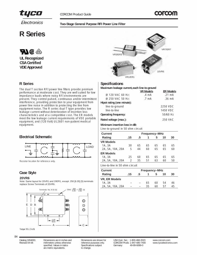
CORCOM Product Guide
Two-Stage General Purpose RFI Power Line Filter
The dual T section RFI power line filters provide premiumperformance at moderate cost. They are well suited for lowimpedance loads where noisy RFI environments arepresent. They control pulsed, continuous and/or intermittentinterference, providing protection to your equipment frompower line noise in addition to protecting the line fromequipment noise. The R series dual T type provides lowleakage current without deterioration of insertion losscharacteristics and at a competitive cost. The ER modelsmeet the low leakage current requirements of VDE portableequipment, and (120 Volt) UL2601 non-patient medicalequipment.
SpecificationsMaximum leakage current,each line-to-ground
VR Models ER Models@ 120 VAC 60 Hz: .4 mA .21 mA@ 250 VAC 50 Hz: .7 mA .36 mA
Hipot rating (one minute):line-to-ground 2250 VDCline-to-line 1450 VDC
Operating frequency: 50/60 Hz
Rated voltage (max.): 250 VAC
Minimum insertion loss in dB:Line-to-ground in 50 ohm circuit
Current Frequency–MHzRating .15 .5 1 5 10 30
VR Models1A, 3A 30 65 65 65 65 652A, 5A, 10A, 20A 5 44 60 65 65 60
ER Models 1A, 3A 25 60 65 65 65 652A, 5A, 10A, 20A 2 35 51 63 60 50
Line-to-line in 50 ohm circuit
Current Frequency–MHzRating .15 .5 1 5 10 30
VR, ER Models1A, 3A – – 65 60 54 462A, 5A, 10A, 20A – – 35 60 57 45
84Catalog 1654001 Dimensions are in inches and Dimensions are shown for USA Cust. Svc.: 1-800-468-2023 www.corcom.com Revised 04-06 millimeters unless otherwise reference purposes only. CORCOM Prods: 1-847-680-7400 www.tycoelectronics.com
specified. Values in italics Specifications subject Germany: 49-89-6089-0 are metric equivalents. to change.
R Series
R Series
Electrical Schematic
Resistor location for reference only.
LINE LOAD
10VR6
VR7/ER7
VR1/ER1
VR3/ER3
Case Style20VR6Note: Same layout for 20VR1 and 20ER1, except .250 [6.35] (5) terminalsreplace Screw Terminals of 20VR6.
E D B
2.0050.8
A
Terminals: No. 8-32 (5)
C
Slots: .2506.35
.156 3.96
x (4)
Torque 18 ± 2 in.lb
UL RecognizedCSA CertifiedVDE Approved

CORCOM Product Guide
Two-Stage General Purpose RFI Power Line Filter (Continued)
Case DimensionsA B C D E
± .015Part No. (max) (max) (max) (max)± .38
1VR1, 1ER1, 3.35 1.81 1.16 2.375 2.782VR1, 2ER1 85.1 46.0 29.5 60.33 70.61VR3, 1ER3, 2.07 1.81 1.16 2.375 2.782VR3, 2ER3 52.6 46.0 29.5 60.33 70.63VR1, 3ER1, 3.85 2.07 1.16 2.938 3.355VR1, 5ER1 97.8 52.6 29.5 74.63 85.13VR3, 3ER3, 2.56 2.07 1.16 2.938 3.355VR3, 5ER3 65.0 52.6 29.5 74.63 85.13VR7, 3VR7M, 4.33 2.25 1.28 1.575 0.643ER7, 3ER7M 110.0 57.2 32.5 40.01 16.35VR7, 5VR7M, 4.33 2.25 1.28 1.575 0.645ER7, 5ER7M 110.0 57.2 32.5 40.01 16.3
10VR1, 10ER1 3.85 2.07 1.53 2.938 3.3597.8 52.6 38.9 74.63 85.1
10VR3, 10ER3 2.56 2.07 1.53 2.938 3.3565.0 52.6 38.9 74.63 85.1
10VR6 3.96 2.07 1.53 2.938 3.35100.6 52.6 38.9 74.63 85.1
10VR7, 10VR7M, 4.33 2.25 1.53 1.575 0.8810ER7, 10ER7M 110.0 57.2 38.9 40.01 22.420VR1, 20ER1 5.23 3.37 1.53 3.75 4.2020VR6 132.8 85.6 38.9 95.25 106.7
85Catalog 1654001 Dimensions are in inches and Dimensions are shown for USA Cust. Svc.: 1-800-468-2023 www.corcom.com Revised 04-06 millimeters unless otherwise reference purposes only. CORCOM Prods: 1-847-680-7400 www.tycoelectronics.com
specified. Values in italics Specifications subject Germany: 49-89-6089-0 are metric equivalents. to change.
RFIPow
erLineFilters
R SeriesCase Styles
Part Numbers
01VR1 01ER101VR3 01ER302VR1 02ER102VR3 02ER303VR1 03ER103VR3 03ER303VR7 03ER703VR7M 03ER7M05VR1 05ER105VR3 05ER305VR7 05ER705VR7M 05ER7M10VR1 10ER110VR3 10ER710VR6 10ER7M10VR7 20ER110VR7M20VR120VR6
Line Cord (R7/R7M): GA400
R1 (except 20 Amp)
DEA C
B
Typical dimensions:Terminals: .250 [6.35] (5) Holes: .07 [1.8] Dia.(4)Mounting Holes: .188 [4.78] Dia. (2) Slot: .07 x .16 [1.8 x 4.1]
R3
ADE C
BBrown
Blue
Brown
Blue
Green/Yellow
C
B
ED
A
Terminals: No. 8-32 (5)
Mounting holes .188 [4.78] Dia. (2)
Typical dimensions:Wire leads: 4.0 [101.6] Min. Mounting Holes: .188 [4.78] Dia. (2)
Torque: 18 ± 2 in.lb
R7 & R7M (with metric insert)
10VR6
A
Tapped insert:
D B
EC
.2355.96
1.57540.01
.1573.98
.91023.11
Dia. (2)
1.29532.89
R
No. 6-32 x 1/4 (2)-R7No. M-3 x .5 (2)-R7M
Typical dimensions:Terminals: .250 [6.35] (5) Holes: .07 [1.8] Dia.(4)Mounting Holes: .188 [4.78] Dia. (2) Slot: .07 x .16 [1.8 x 4.1]
† ±.02 [±.5]
†
†
†
Tolerance ±.005 [0.13]
Panel Cutout (back mount)

CORCOM Product Guide
Multipurpose Power Line RFI Filter for Emission Control and High-Noise Industrial Environments
The S series filters combine Tyco Electronics successfulline-to-ground interference rejection filters with additionalcircuitry designed to reduce line-to-line noise andtransients.
These filters feature an N = 2 ( “L” ) line-to-groundimpedance to common mode noise and an N = 3 ( “Pi” )differential mode impedance line-to-line. This series isdesigned for use when equipment impedance at RFfrequencies is high.
These filters will better protect equipment frommalfunctions due to conducted interference coming intothe equipment from the line, especially line-to-line noiseand transients. They will also provide needed noisesuppression to allow most equipment (including switch-mode power supplies) to meet FCC specifications forconducted emissions.
The S series is also effective to control emissions inequipment using SCR and T2L circuits, for compliance with FCC Part 15, Subpart J, and EN55022, Level A, down to 150kHz.
SpecificationsMaximum leakage current,each line-to-ground
@ 120 VAC 60 Hz: .4 mA@ 250 VAC 50 Hz: .7 mA
Hipot rating (one minute):line-to-ground 2250 VDCline-to-line 1450 VDC
Operating frequency: 50/60 Hz
Rated voltage (max.): 250 VAC
Rated current:3VS 3A6VS 6A10VS 10A20VS 20A
Minimum insertion loss in dB:Line-to-ground in 50 ohm circuit
Current Frequency–MHzRating .15 .5 1 2 5 10 20 30
3A 15 27 35 40 32 44 47 476A 15 27 35 40 32 44 47 47
10A 15 27 35 40 32 44 47 4720A 15 30 38 38 32 43 42 40
Line-to-line in 50 ohm circuit
Current Frequency–MHzRating .15 .3 .5 1 2 5 10 20 30
3A 35 50 65 65 65 60 50 40 456A 35 50 65 65 65 60 45 48 48
10A 35 50 65 65 65 60 50 40 4520A 35 50 65 65 65 60 45 48 48
86Catalog 1654001 Dimensions are in inches and Dimensions are shown for USA Cust. Svc.: 1-800-468-2023 www.corcom.com Revised 04-06 millimeters unless otherwise reference purposes only. CORCOM Prods: 1-847-680-7400 www.tycoelectronics.com
specified. Values in italics Specifications subject Germany: 49-89-6089-0 are metric equivalents. to change.
S Series
S Series
20VS1
3A, 6A, 10A
Electrical Schematics
3A, 6A, 10A
20A
Resistor location for reference only.
LINE LOAD
LINE LOAD
UL RecognizedCSA CertifiedVDE Approved

CORCOM Product Guide
Multipurpose Power Line RFI Filter for Emission Control and High-Noise Industrial Environments (Continued)
87Catalog 1654001 Dimensions are in inches and Dimensions are shown for USA Cust. Svc.: 1-800-468-2023 www.corcom.com Revised 04-06 millimeters unless otherwise reference purposes only. CORCOM Prods: 1-847-680-7400 www.tycoelectronics.com
specified. Values in italics Specifications subject Germany: 49-89-6089-0 are metric equivalents. to change.
RFIPow
erLineFilters
Case Styles Case Dimensions
Part No. A B C D E± .015(max) (max) (max) (max)±.38
3VS1 3.36 1.82 1.16 2.375 2.7885.3 46.2 29.5 60.33 70.6
6VS1 3.86 2.08 1.53 2.938 3.3498.0 52.8 38.9 74.63 84.8
10VS1 3.86 2.08 1.53 2.938 3.3498.0 52.8 38.9 74.63 84.8
20VS1 5.23 3.38 1.53 3.75 4.20132.8 85.9 38.9 95.25 106.7
20VS6 5.34 3.38 1.53 3.75 4.20135.6 85.9 38.9 95.25 106.7
S Series
Typical dimensions:Terminals: .250 [6.35] (5) Holes: .07 [1.8] Dia.(4) Slot: .07 x .16 [1.8 x 3.8] Mounting holes: .188 [4.78] Dia. (2)
Part Numbers
3VS1 10VS16VS1 20VS1
20VS6
3A, 6A, 10A
DEA C
B
Typical dimensions:Terminals: .250 [6.35] (5) Holes: .07 [1.8] Dia.(4) Slot: .07 x .16 [1.8 x 4.1] Mounting holes: .25 x .156 [6.35 x 3.96] Dia. (4)
20VS1
DE
A C
B
Slots: .250 x .1566.35 x 3.96
(4)
2.0050.8
Typical dimensions:Mounting holes: .25 x .156 [6.35 x 3.96] Dia. (4) Torque 18 ± 2 in.lb
20VS6
E
2.0050.8
A
Terminals: No. 8-32 (5)
C
B D

CORCOM Product Guide
3 to 40 Amp High Performance K Series RFI Power Line Filtersfor SMPS Emission Control
This series of RFI filters was designed to reduce conductednoise to acceptable limits for equipment that must complywith the FCC specifications in the USA and CISPRspecifications in Europe.
The SK (Super K) series filters use significantly higherelement values than the general purpose K series, whichmakes them better suited for equipment with line-to-groundand line-to-line conducted emissions, including switchmode power supplies.
The ESK models meet the very low leakage currentrequirements of VDE portable equipment and (120 Volt) UL 544 non-patient medical equipment.
Models ESK6C and VSK6C additionally incorporate aseparate ground-circuit inductor to isolate the equipmentchassis from power line ground at RF frequencies.
SpecificationsMaximum leakage current,each line-to-ground
VSK Models ESK Models3, 6 & 10 Amps@ 120 VAC 60 Hz: .4 mA .21 mA@ 250 VAC 50 Hz: .7 mA .36 mA20, 30 & 40 Amps@120 VAC 60 Hz: .75 mA .3 mA@250 VAC 50 Hz: 1.25 mA .5 mA
Hipot rating (one minute):line-to-ground 2250 VDCline-to-line 1450 VDC
Operating frequency: 50/60 Hz
Rated voltage (max.): 250 VAC
Rated current:3VSK/3ESK 3A6VSK/6ESK 6A10VSK/10ESK 10A20VSK/20ESK 20A30VSK/30ESK 30A40VSK 40A
88Catalog 1654001 Dimensions are in inches and Dimensions are shown for USA Cust. Svc.: 1-800-468-2023 www.corcom.com Revised 04-06 millimeters unless otherwise reference purposes only. CORCOM Prods: 1-847-680-7400 www.tycoelectronics.com
specified. Values in italics Specifications subject Germany: 49-89-6089-0 are metric equivalents. to change.
SK Series
SK Series – 3, 6 & 10 Amp Models
Electrical Schematic
Resistor location for reference only.
LINE LOAD
6C modelsonly
SK1
SK3
SK7
UL RecognizedCSA CertifiedVDE Approved
SK1

CORCOM Product Guide
3 to 40 Amp High Performance K Series RFI Power Line Filtersfor SMPS Emission Control (Continued)
Case Styles
89Catalog 1654001 Dimensions are in inches and Dimensions are shown for USA Cust. Svc.: 1-800-468-2023 www.corcom.com Revised 04-06 millimeters unless otherwise reference purposes only. CORCOM Prods: 1-847-680-7400 www.tycoelectronics.com
specified. Values in italics Specifications subject Germany: 49-89-6089-0 are metric equivalents. to change.
RFIPow
erLineFilters
SK SeriesSpecifications (continued)
Minimum insertion loss in dB:
Line-to-ground in 50 ohm circuit
Current Frequency - MHzRating .01 .08 .1 .15 .5 1 5 10 30
VSK Models3A, 6A, 10A 4 23 25 29 43 44 42 42 30
20A 7 23 25 29 43 44 48 48 4830A 2 13 14 15 27 31 46 51 3940A 2 15 18 22 40 43 45 50 30
ESK Models3A, 6A, 10A 4 22 24 28 42 40 36 36 27
20A 7 22 24 28 35 38 45 45 4530A 2 13 15 15 27 31 40 41 36
Line-to-line in 50 ohm circuit
Current Frequency - MHzRating .01 .08 .1 .15 .5 1 5 10 30
VSK Models3A, 6A 1 3 10 25 59 65 62 40 4010A 1 3 3 10 55 65 65 50 5020A 1 10 8 8 45 60 65 60 6030A 5 13 13 13 60 60 51 43 4340A 7 14 16 30 65 65 65 57 50
ESK Models3A, 6A 1 3 10 25 59 65 62 40 4010A 1 3 3 10 55 65 65 65 4520A 1 10 8 8 45 60 65 60 6030A 5 12 12 13 60 60 51 43 43
Typical dimensions:Terminals: .250 [6.35] (5) Holes: .07 [1.8] Dia.(4) Slot: .07 x .16 [1.8 x 4.1] Mounting holes: .188 [4.78] Dia. (2)
SK1
DEA C
B
Typical dimensions:Wire leads: 4.0 [101.6] Min. Mounting holes: .188 [4.78] Dia. (2)
3A-SK3
ADE C
BBrown
Blue
Brown
Blue
Green/Yellow
Typical dimensions:Wire leads: 4.0 [101.6] Min. Mounting holes: .188 [4.78] Dia. (2)
6A & 10A-SK3
ADE
Brown
Blue
Brown
Blue
Grn/Yel
C
B
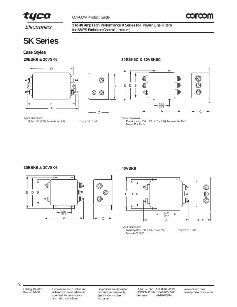
CORCOM Product Guide
90Catalog 1654001 Dimensions are in inches and Dimensions are shown for USA Cust. Svc.: 1-800-468-2023 www.corcom.com Revised 04-06 millimeters unless otherwise reference purposes only. CORCOM Prods: 1-847-680-7400 www.tycoelectronics.com
specified. Values in italics Specifications subject Germany: 49-89-6089-0 are metric equivalents. to change.
SK SeriesCase Styles20ESK6 & 20VSK6
Typical dimensions:Holes: .188 [4.78] Terminals No. 8-32 Torque: 18 ± 2 in.lb
C
B
E
D
A
30ESK6 & 30VSK6
E D B
A C
1.5038.1
Typical dimensions:Mounting slots: .203 x .156 [5.16x 3.96] Torque: 27 ± 3 in.lbTerminals (5): 10-32
40VSK6
E D B
A C
2.0050.5
Typical dimensions:Mounting slots: .250 x .156 [6.35 x 3.96] Terminals No. 10-32Torque: 27 ± 3 in.lb
30ESK6C & 30VSK6C
E D B
A C
1.5038.1
3 to 40 Amp High Performance K Series RFI Power Line Filtersfor SMPS Emission Control (Continued)

CORCOM Product Guide
A B C D E± .020Part No. (max) (max) (max) (max)± .51
30ESK6,30ESK6C 4.92 3.12 2.75 3.437 4.0030VSK6, 125.0 79.25 69.85 87.3 101.630VSK6C
40VSK6 6.00 3.12 2.18 3.50 3.96152.4 79.25 55.4 88.9 100.6
91Catalog 1654001 Dimensions are in inches and Dimensions are shown for USA Cust. Svc.: 1-800-468-2023 www.corcom.com Revised 04-06 millimeters unless otherwise reference purposes only. CORCOM Prods: 1-847-680-7400 www.tycoelectronics.com
specified. Values in italics Specifications subject Germany: 49-89-6089-0 are metric equivalents. to change.
RFIPow
erLineFilters
SK Series
Part Numbers
0 3VSK1 03ESK103VSK3 03ESK303VSK7 03ESK703VSK7M 03ESK7M06VSK1 06ESK106VSK3 06ESK306VSK7 06ESK706VSK7M 06ESK7M10VSK1 10ESK110VSK3 10ESK310VSK7 10ESK710VSK7M 10ESK7M20ESK6 30VSK620VSK6 30VSK6C30ESK6 40VSK630ESK6C
Line Cord No. (K7/K7M) GA400
Recommended Panel Cutout
Case Dimensions
Part No. A B C D E± .015(max) (max) (max) (max)± .38
3VSK1, 3ESK1 3.85 2.07 1.16 2.938 3.3597.8 52.6 29.5 74.63 85.1
3VSK3, 3ESK3 2.56 2.07 1.16 2.938 3.3565.0 52.6 29.5 74.63 85.1
3VSK7, 3VSK7M, 3.21 2.25 1.53 1.575 0.633ESK7, 3ESK7M 81.5 57.2 38.9 40.01 16.0
6VSK1, 6ESK1 4.34 2.25 1.28 3.427 3.83110.2 57.2 32.5 87.05 97.3
6VSK3, 6ESK3 3.05 2.25 1.28 3.427 3.8377.5 57.2 32.5 87.05 97.3
6VSK7, 6VSK7M, 3.21 2.25 1.78 1.575 0.636ESK7, 6ESK7M 81.5 57.2 45.2 40.01 16.0
10VSK1, 10ESK1 4.97 2.25 1.78 4.063 4.46126.2 57.2 45.2 103.2 113.3
10VSK3, 10ESK3 3.69 2.25 1.78 4.063 4.4693.7 57.2 45.2 103.2 113.3
10VSK7, 10VSK7M, 4.34 2.25 1.78 1.575 0.6310ESK7, 10ESK7M 110.0 57.2 45.2 40.01 16.0
20ESK6, 5.09 2.25 1.78 4.063 4.4620VSK6 127.3 57.2 45.2 103.2 129.3
† ±.02 [±.5]
†
†
†
Typical dimensions:Terminals: .250 [6.35] (3) Holes: .07 [1.8] Dia.(2) Slot: .07 x .16 [1.8 x 4.1]
SK7 & SK7M (with metric insert)
A
Tapped insert:
D B
EC
.2356.0
1.57540.0
.1574.0
.91023.1
Dia. (2)
1.29532.9
R
No. 6-32 x 1/4 (2)-SK7No. M-3 x .5 (2)-SK7M
A
Tapped insert:
D B
EC
.2356.0
1.57540.0
.1574.0
.91023.1
Dia. (2)
1.29532.9
R
No. 6-32 x 1/4 (2)-SK7No. M-3 x .5 (2)-SK7M
Tolerance ±.005 [0.13]
Panel Cutout (back mount)
ESK6/VSK6
Case Dimensions
Part No. A B C D E± .015(max) (max) (max) (max)± .38
3VSK1, 3ESK1 3.85 2.07 1.16 2.938 3.3597.8 52.6 29.5 74.63 85.1
3VSK3, 3ESK3 2.56 2.07 1.16 2.938 3.3565.0 52.6 29.5 74.63 85.1
3VSK7, 3VSK7M, 3.21 2.25 1.53 1.575 0.633ESK7, 3ESK7M 81.5 57.2 38.9 40.01 16.0
6VSK1, 6ESK1 4.34 2.25 1.28 3.427 3.83110.2 57.2 32.5 87.05 97.3
6VSK3, 6ESK3 3.05 2.25 1.28 3.427 3.8377.5 57.2 32.5 87.05 97.3
6VSK7, 6VSK7M, 3.21 2.25 1.78 1.575 0.636ESK7, 6ESK7M 81.5 57.2 45.2 40.01 16.0
10VSK1, 10ESK1 4.97 2.25 1.78 4.063 4.46126.2 57.2 45.2 103.2 113.3
10VSK3, 10ESK3 3.69 2.25 1.78 4.063 4.4693.7 57.2 45.2 103.2 113.3
10VSK7, 10VSK7M, 4.34 2.25 1.78 1.575 0.6310ESK7, 10ESK7M 110.0 57.2 45.2 40.01 16.0
20ESK6, 5.09 2.25 1.78 4.063 4.4620VSK6 127.3 57.2 45.2 103.2 129.3
3 to 40 Amp High Performance K Series RFI Power Line Filtersfor SMPS Emission Control (Continued)

CORCOM Product Guide
Cost Effective, Reduced Footprint, Shielded Line Filter
With one of the smallest footprints available on the markettoday, the SRB Series features a complete shield designwith various capacitance values. This unique combinationoffers varying levels of common mode performance whichminimizes conducted emissions and may reduce radiatedemissions.
The SRB Series is rated up to 15 Amps, 250 VAC.* All configurations are available unfiltered or with one of eightdifferent capacitor values to address different performanceneeds. The SRB Series features a multitude of installationand termination options including flange or snap-in mount-ing, and FASTON terminal, wire leaded, and pin terminationoptions. This product is ideally suited for power supplies orother applications which require a minimum footprint lowcost solution.
*10 Amps VDE
SpecificationsMaximum leakage current,each line-to-ground
Capacitor Identifier/Value @120 VAC @250 VAC60 Hz 50Hz
Blank/None 2uA 5uAQ / 33pF 2.1uA 3.65uAR / 100pF 9.6uA 16.6uAS / 220pF 19.2uA 33.2uAT / 330pF 24.0uA 41.5uAW / 470pF 0.04mA 0.07mAX / 1000pF 0.07mA 0.13mAY / 2200pF 0.16mA 0.28mAZ / 3300pF 0.24mA 0.42mA
Hipot rating (one minute):line-to-ground 1500 VDCline-to-line 1450 VDC
Operating frequency: 50/60 Hz
Rated voltage (max.): 250 VAC
Minimum insertion loss in dB:Line-to-ground in 50 ohm circuit
92Catalog 1654001 Dimensions are in inches and Dimensions are shown for USA Cust. Svc.: 1-800-468-2023 www.corcom.com Revised 04-06 millimeters unless otherwise reference purposes only. CORCOM Prods: 1-847-680-7400 www.tycoelectronics.com
specified. Values in italics Specifications subject Germany: 49-89-6089-0 are metric equivalents. to change.
SRB Series
SRB Series
UL RecognizedCSA CertifiedVDE Approved
Electrical Schematic
Capacitor Options
PCB Layout
Case Styles
Capacitor Value Identifier Capacitor ValueQ 33pFR 100pFS 220pFT 330pFW 470pFX 1000pFY* 2200pFZ * 3300pF
*Not available in SRB8 Styles.
SRB1
DE
A B
C
0.551
0.520
0.075 Dia.
Center pin topanel .685 _ .015+
Capacitor Frequency MhzID 1 5 10 50 100 300Q - - - - - 20R - - - 3 6 22S - - 1 6 17 19T - - 2 13 13 19W - 2 4 18 13 20X - 5 9 25 10 17Y 1 10 15 20 8 22Z 2 14 18 17 7 15

CORCOM Product Guide
Cost Effective, Reduced Footprint, Shielded Line Filter (Continued)
93Catalog 1654001 Dimensions are in inches and Dimensions are shown for USA Cust. Svc.: 1-800-468-2023 www.corcom.com Revised 04-06 millimeters unless otherwise reference purposes only. CORCOM Prods: 1-847-680-7400 www.tycoelectronics.com
specified. Values in italics Specifications subject Germany: 49-89-6089-0 are metric equivalents. to change.
RFIPow
erLineFilters
SRB Series
Recommended Panel Cutouts
.2345.94
.90022.9
1.57540.01
1.20030.48 0.12
3.05 TYP.
∅ 0.1403.56 .820
20.8
1.57540.01
1.20030.48
2X
∅ 0.1403.56
2X
RR
TYP.
A±.002.05 0.188
4.784X
0.815±.00220.70.05
RPanel Thickness A Dim. ±.002.031-.052 [.79-1.32] 1.260 [32.00]0.046-0.068 [1.17-1.73] 1.350 [34.29]
Notes:Tolerance ± .005 [0.13] Panel Thickness .031-.047 [.78-1.19] SRB1 and SRB8 styles allow for front or back mountingSRB2 and SRBP allow for back mounting only
Case Styles (continued)
E
D
C
A
B
SRBS8
SRB2
C
DE
A
B
SRBP
E
D
C
A
B
SRB8
B
A
C
E
D
Case Dimensions
Part No. A B C D E± .015(max) (max) (max) (max)± .380
15SRB1 1.75 1.13 0.96 1.580 2.0444.45 28.70 24.38 40.00 51.76
15SRB2 1.54 1.13 0.96 1.58 2.0439.12 28.70 24.38 40.00 51.76
15SRBP 1.54 1.13 0.96 1.58 2.0439.12 28.70 24.38 40.00 51.76
15SRB8 .94 1.13 0.96 1.58 2.0423.82 28.70 24.38 40.00 51.76
15SRBS1 1.75 1.13 0.96 1.19 1.4144.45 28.70 24.38 30.10 35.81
15SRBS8 1.12 1.13 0.96 1.19 1.4128.45 28.70 24.38 30.10 35.81
Typical dimensions:FASTON Terminals: .250 [6.35] (3) Holes: .07 [1.8] Dia.(2) Slot: .07 x .16 [1.8 x 4.1]Mounting holes: .132 [3.35] Dia. (2) w/.260 Dia. x 90˚ countersunk for a #4 flathead screwStyle 8 wire leads: 4.0 [101.6] min. 1-15A, 18AWG; 20A, 14 AWG/UL1015
SRBS
SRB
Panel Cutout (front mount) Panel Cutout (back mount)
E
AD
B
C
SRBS1
Part Numbers
015SRB115SRBS115SRB215SRB815SRBS815SRBP15SRB1-Q15SRBS1-Q15SRB2-Q15SRB8-Q15SRBS8-Q15SRBP-Q15SRB1-R15SRBS1-R15SRB2-R15SRB8-R15SRBS8-R15SRBP-R
15SRB1-S15SRBS1-S15SRB2-S15SRB8-S15SRBS8-S15SRBP-S15SRB1-T15SRBS1-T15SRB2-T15SRB8-T15SRBS8-T15SRBP-T15SRB1-W15SRBS1-W15SRB2-W15SRB8-W15SRBS8-W15SRBP-W
15SRB1-X15SRBS1-X15SRB2-X15SRB8-X15SRBS8-X15SRBP-X15SRB1-Y15SRBS1-Y15SRB2-Y15SRB8-Y15SRBS8-Y15SRBP-Y15SRB1-Z15SRBS1-Z15SRB2-Z15SRB8-Z15SRBS8-Z15SRBP-Z

CORCOM Product Guide
High Performance RFI Power Line Filters for Switching Power Supplies
94Catalog 1654001 Dimensions are in inches and Dimensions are shown for USA Cust. Svc.: 1-800-468-2023 www.corcom.com Revised 04-06 millimeters unless otherwise reference purposes only. CORCOM Prods: 1-847-680-7400 www.tycoelectronics.com
specified. Values in italics Specifications subject Germany: 49-89-6089-0 are metric equivalents. to change.
T Series
T SeriesThe T series RFI filters provide superior common-mode andpremium differential-mode attenuation, exceeded only bythat of Q series filters. This remarkable performance isavailable for current ratings up to 20 amps in packagesizes smaller than comparable EP series filters. In fact, the10-amp T is smaller than the 6-amp EP.
These filters are a size and cost-effective choice for verynoisy equipment that must meet the emission limits of FCCParts 15 and 18 or EN55022, A-level. In some cases, thesefilters can even bring equipment into compliance withEN55022, B-level. This performance is accomplished withcircuits that still meet the very low leakage currentrequirements of VDE portable equipment, and (120 Volt)UL544 non-patient medical equipment Minimum insertion loss in dB:
Electrical Schematics
Resistor location for reference only.
LINE LOAD
3ET & 6ET
LINE LOAD
10ET & 10VT
LINE LOAD
15ET & 15VT, 20ET & 20VT
SpecificationsMaximum leakage current,each line-to-ground
ET Models VT Models@ 120 VAC 60 Hz: .30 mA .75 mA
(3A, 6A, 10A)@ 120 VAC 60 Hz: .30 mA 1.2 mA
(15A, 20A)@ 250 VAC 50 Hz: .50 mA 1.25 mA
(3A, 6A, 10A)@ 250 VAC 50 Hz: .50 mA 2.0 mA
(15A 20A)Hipot rating (one minute):
line-to-ground 2250 VDCline-to-line 1450 VDC
Operating frequency: 50/60 Hz
Rated voltage (max.): 250 VAC
UL RecognizedCSA CertifiedVDE Approved
Line-to-ground in 50 ohm circuitCurrent Frequency–MHzRating .01 .03 .05 .15 .5 1 2 5 10 20 30
ET Models3A 22 32 36 46 47 44 43 40 42 42 426A 16 26 30 41 47 44 43 43 40 42 42
10A 12 22 26 36 47 42 42 40 42 42 4515A 8 17 22 31 43 44 44 42 47 52 4320A 3 12 17 26 34 36 37 37 42 47 38
VT Models10A 12 22 26 38 52 50 50 50 50 50 5015A 8 17 22 33 52 52 52 52 57 45 3520A 3 12 17 29 42 47 50 51 55 40 30
Line-to-line in 50 ohm circuitCurrent Frequency–MHzRating .01 .03 .05 .15 .5 1 2 5 10 20 30
ET Models3A 3 1 30 61 70 70 70 50 50 50 556A 4 2 14 51 70 70 70 65 47 50 55
10A 7 12 17 52 70 70 70 65 55 50 6015A 12 19 15 51 70 70 70 70 70 65 6020A 10 17 13 51 70 70 70 70 67 65 60
VT Models10A 7 12 17 52 70 70 70 65 65 50 6515A 12 19 15 51 70 70 70 70 70 65 6020A 10 17 13 51 70 70 70 70 67 65 60
ET1/VT1

CORCOM Product Guide
High Performance RFI Power Line Filters for Switching Power Supplies (Continued)
95Catalog 1654001 Dimensions are in inches and Dimensions are shown for USA Cust. Svc.: 1-800-468-2023 www.corcom.com Revised 04-06 millimeters unless otherwise reference purposes only. CORCOM Prods: 1-847-680-7400 www.tycoelectronics.com
specified. Values in italics Specifications subject Germany: 49-89-6089-0 are metric equivalents. to change.
RFIPow
erLineFilters
T SeriesCase Styles
Case DimensionsA B C D E
± .015Part No. (max) (max) (max) (max)± .38
3ET1, 6ET1 3.56 2.15 1.81 2.938 3.3890.4 54.6 46.0 74.63 85.9
3ET3, 6ET3 2.55 2.15 1.81 2.938 3.3864.8 54.6 46.0 74.63 85.9
3ET7, 6ET7 3.52 2.25 1.78 1.575 0.6389.4 57.2 45.2 40.01 16.0
10ET1, 10VT1 4.69 2.27 1.80 4.063 4.47119.1 57.7 45.7 103.2 113.5
10ET3, 10VT3 3.69 2.27 1.80 4.063 4.4793.7 57.7 45.7 103.2 113.5
15ET1, 15VT1, 5.45 3.12 2.18 3.500 3.9620ET1, 20VT1 138.4 79.2 55.4 88.9 100.6
15ET6, 15VT6, 5.95 3.12 2.18 3.500 3.9620ET6, 20VT6 151.1 79.2 55.4 88.9 100.6
† ±.02 [±.5]
†
Part Numbers
3ET13ET33ET76ET16ET36ET7
10ET110ET315ET115ET620ET120ET6
10VT110VT315VT115VT620VT120VT6
Line Cord No. (T7) GA400
Typical dimensions:Terminals: .250 [6.35] (5) Holes: .07 [1.8] Dia.(4) Slot: .07 x .16 [1.8 x 4.1] Mounting holes: .188 [4.78] Dia. (2)
T1
A
B
CDE
Typical dimensions:Wire leads: 4.0 [101.6] Min. Mounting holes: .188 [4.78] Dia. (2)
T3
ADE
Brown
Blue
Brown
Blue
Grn/Yel
C
B
Typical dimensions:Terminals: .250 [6.35] (5) Holes: .07 [1.8] Dia.(4) Slot: .07 x .16 [1.8 x 4.1] Mounting holes: .203 x .156 [5.16 x3.96] Dia. (4)
15A, 20A-T1
B
C
E D
2.00± .01
A
50.8±.25
E D B
2.00 .0150.8 .25
A C
Typical dimensions:Terminals: No. 8-32 Torque: 18 ± 2 in.lb
15A, 20A-T6
T7
A
Tapped insert:
D B
EC
No. 6-32 x 1/4 (2)-R7
1.29532.9
1.57540.0
0.91023.1
0.2356.0
R.0.157
4.0Dia.

CORCOM Product Guide
RFI Filter for Power Factor Corrected Power Supplies
96Catalog 1654001 Dimensions are in inches and Dimensions are shown for USA Cust. Svc.: 1-800-468-2023 www.corcom.com Revised 04-06 millimeters unless otherwise reference purposes only. CORCOM Prods: 1-847-680-7400 www.tycoelectronics.com
specified. Values in italics Specifications subject Germany: 49-89-6089-0 are metric equivalents. to change.
U Series
U SeriesThe U series is designed to meet the RFI needs created by power factor corrected power supplies. Thishigh performance filter offers a high impedance circuit tomismatch the power supply’s impedance characteristics.The economical design allows superior performance at a reasonable price.
The PC board mountable version has a low profile casewhich adapts well to most modular power converterapplications.
All models meet low leakage current requirements of VDEportable equipment, and (120 Volt) UL544 and UL2601non-patient medical equipment.
SpecificationsMaximum leakage current,each line-to-ground
@ 120 VAC 60 Hz: .30 mA@ 250 VAC 50 Hz: .50 mA
Hipot rating (one minute):line-to-ground 2250 VDCline-to-line 1450 VDC
Operating frequency: 50/60 Hz
Rated voltage (max.): 250 VAC
Rated current: 6.5 amps
Minimum insertion loss in dB:Line-to-ground in 50 ohm circuit
Current Frequency-MHzRating .05 .1 .15 .5 1 5 10 30
6A 4 30 40 70 70 70 65 50
Line-to-line in 50 ohm circuit
Current Frequency-MHzRating .05 .1 .15 .5 1 5 10 30
6A 10 35 45 70 70 70 65 55
6EU1 6EUP
Electrical Schematic
Resistor location for reference only.
LINE LOAD
UL RecognizedCSA CertifiedVDE Approved 6EU1

CORCOM Product Guide
RFI Filter for Power Factor Corrected Power Supplies (Continued)
97Catalog 1654001 Dimensions are in inches and Dimensions are shown for USA Cust. Svc.: 1-800-468-2023 www.corcom.com Revised 04-06 millimeters unless otherwise reference purposes only. CORCOM Prods: 1-847-680-7400 www.tycoelectronics.com
specified. Values in italics Specifications subject Germany: 49-89-6089-0 are metric equivalents. to change.
RFIPow
erLineFilters
U SeriesCase Styles Case Dimensions
A B C D E± .015Part No. (max) (max) (max) (max)± .38
6EUP 4.70 2.51 1.22 — —119.4 63.8 31.0
6EU1 4.95 2.27 1.80 4.060 4.47125.73 57.66 45.72 103.12 113.54
6EUP
A
B
C
.14 3.56 .39
9.91
6-32 insert (3) ground (2)
6EU1
DEA
C
B
Typical dimensions:Terminals: .250 [6.35] (5) Holes: .07 [1.8] Dia.(4) Slot: .07 x .16 [1.8 x 4.1] Mounting holes: .188 [4.78] Dia. (2)
Part Numbers
6EUP 6EUP1
Recommended PC Board Layout
1.5038.1
2.1053.34
2.99 75.95
.79 20.07
.7519.05
1.50 38.1
.52 13.21
.26 6.60
.157 Dia. (3) .075 Dia. (6)
LINE LOAD

CORCOM Product Guide
98Catalog 1654001 Dimensions are in inches and Dimensions are shown for USA Cust. Svc.: 1-800-468-2023 www.corcom.com Revised 04-06 millimeters unless otherwise reference purposes only. CORCOM Prods: 1-847-680-7400 www.tycoelectronics.com
specified. Values in italics Specifications subject Germany: 49-89-6089-0 are metric equivalents. to change.
V and W Series
V and W Series
Multipurpose Power Line RFI Filter for Emission Control and High-Noise Industrial Environments
The V series and W series filters will better protectequipment from malfunctions due to conductedinterference coming into the equipment from the line,especially line-to-line noise and transients. They will alsoprovide needed noise suppression to allow mostequipment to meet FCC specifications for conductedemissions.
V Series – offers an N = 3 (“T”) line-to-ground impedanceto common mode and an N = 5 (“Dbl. Pi”) impedance forline-to-line differential mode interference. The filters aredesigned for susceptibility use when equipmentimpedance at RF frequencies is low.
W Series – provides an N = 4 (“Dbl. L”) line-to-groundimpedance for common mode and an N = 5 (“Dbl. Pi”)impedance for line-to-line differential mode interference.The filters are designed for use when equipmentimpedance at RF frequencies is high. The two-stageconstruction provides excellent suppression at highfrequency.V series and W series filters are also effective to controlemissions in equipment using SCR and T2Lcircuits, forcompliance with FCC Part 15, Subpart J, and EN55022,Level A, down to 150kHz.
SpecificationsMaximum leakage current,each line-to-ground
@ 120 VAC 60 Hz: 0.5 mA@ 250 VAC 50 Hz: .82 mA
Hipot rating (one minute):line-to-ground 2250 VDCline-to-line 1450 VDC
Operating frequency: 50/60 Hz
Rated voltage (max.): 250 VAC
Rated current:
3VV/3VW 3A6VV/6VW 6A10VV/10VW 10A20VV/20VW 20A
Minimum insertion loss in dB:Line-to-ground in 50 ohm circuitCurrent Frequency–MHzRating .15 .5 1 2 5 10 20 30
V Series3A 15 27 38 47 55 55 50 486A 15 27 28 47 55 55 50 48
10A 15 27 38 47 55 55 50 4820A 15 30 41 49 60 46 36 30
W Series3A 13 25 20 45 65 65 65 636A 18 30 34 40 65 65 57 47
10A 18 30 34 40 65 65 57 4720A 18 30 34 40 65 65 57 47
Line-to-line in 50 ohm circuitCurrent Frequency–MHzRating .15 .3 .5 1 2 5 10 20 30
V Series3A 25 25 65 65 63 60 52 50 506A 40 54 65 65 65 65 60 57 55
10A 25 25 65 65 63 60 52 50 5020A 25 25 65 65 63 60 52 50 50
W Series3A 25 40 65 65 65 62 55 35 356A 30 54 65 65 65 60 55 38 38
10A 25 25 65 65 65 65 50 45 4520A 25 25 65 65 65 65 50 45 45
Electrical Schematics
LINE LOAD
LINE LOAD
LINE LOAD
V Series
W Series 3A, 6A, 10A
W Series 20A
Resistor location for reference only.
VV1/VW13A, 6A, 10A
VV6/VW620A
UL RecognizedCSA CertifiedVDE Approved

CORCOM Product Guide
99Catalog 1654001 Dimensions are in inches and Dimensions are shown for USA Cust. Svc.: 1-800-468-2023 www.corcom.com Revised 04-06 millimeters unless otherwise reference purposes only. CORCOM Prods: 1-847-680-7400 www.tycoelectronics.com
specified. Values in italics Specifications subject Germany: 49-89-6089-0 are metric equivalents. to change.
RFIPow
erLineFilters
V and W SeriesCase Styles
Case DimensionsA B C D E
± .015Part No. (max) (max) (max) (max)± .38
3VV1, 3VW1 3.36 1.82 1.28 2.375 2.7885.3 46.2 32.5 60.33 70.6
6VV1, 6VW1 3.86 2.08 1.53 2.938 3.3498.0 52.8 38.9 74.63 84.8
10VV1,10VW1 3.86 2.08 1.53 2.938 3.3498.0 52.8 38.9 74.63 84.8
20VV1, 20VW1 5.23 3.38 1.53 3.750 4.20132.8 85.9 38.9 95.25 106.7
20VV6, 20VW6 5.34 3.38 1.53 3.760 4.20135.64 85.9 38.9 95.5 106.7
20VW7 5.65 3.12 2.29 — —143.51 79.25 58.17
Multipurpose Power Line RFI Filter for Emission Control and High-Noise Industrial Environments (Continued)
3A, 6A, 10A
DEA C
B
20VV1/20VW1
DE
A C
B
Slots: .250 x .1566.35 x 3.96
(4)
2.0050.8
20VW7 Panel Cutout
1.2230.99
1.6040.46
.7519.05
2.3058.42
CL
2.1253.85
.1573.98
Dia.
.2195.56
R MTG. PLANE
Part Numbers
V Series03VV106VV110VV120VV1*20VV6*
W Series03VW106VW110VW120VW1*20VW6*20VW7*
Typical dimensions:Terminals: .250 [6.35] (5) Holes: .07 [1.8] Dia.(4) Slot: .07 x .16 [1.8 x 4.1] Mounting holes: .188 [4.78] Dia. (2)
Typical dimensions:Terminals: .250 [6.35] (5) Holes: .07 [1.8] Dia.(4) Slot: .07 x .16 [1.8 x 4.1]
20VV6/20VW6
20VW7
E D B
2.0050.8
A
Terminals: No. 8-32 (5)
C
Slots: .2506.35
.156 3.96
x (4)
Torque: 18± 2 in.lb
A
B
C
.047 .0101.19 .25
5.33 .025135.382
2.25 57.15
.380 x 0.218 .010.965 x 5.54 .25
Slots (2)
6-32 Insert (2 places)
* UL, CSA — 20A; VDE — 16A

CORCOM Product Guide
100Catalog 1654001 Dimensions are in inches and Dimensions are shown for USA Cust. Svc.: 1-800-468-2023 www.corcom.com Revised 04-06 millimeters unless otherwise reference purposes only. CORCOM Prods: 1-847-680-7400 www.tycoelectronics.com
specified. Values in italics Specifications subject Germany: 49-89-6089-0 are metric equivalents. to change.
X, Y, Z Series
PC Board Mountable RFI Power Line Filters for Emission Control Applications
X, Y, and Z series RFI filters are compact, PC boardmountable components, designed to consume minimalboard space. They provide a choice of three levels ofperformance, intended to be all the power line filter neededfor the corresponding emission control application.
X Series – designed to bring most digital equipment(including switching power supplies) into compliance withFCC Part 15J, Class B conducted emission limits.
Y Series – designed to bring most digital equipment(including switching power supplies) into compliance withEN55022, Level A, and FCC Part 15J, Class B conductedemission limits.
Z Series – designed to bring most digital equipment(including switching power supplies) into compliance withEN55022, Level B (as well as FCC Part 15J, Class B)conducted emission limits.
This high compliance confidence level is attained byoptimizing the differential mode performance of each seriesfor the frequency range it needs to cover in thecorresponding application. At the same time, excellentcommon mode performance is maintained across thefrequency range of 10kHz to 30MHz, while still meeting thevery low leakage current requirements of SEV and VDEportable equipment.
SpecificationsMaximum leakage current,each line-to-ground
@ 120 VAC 60 Hz: .30 mA@ 250 VAC 50 Hz: .50 mA
Hipot rating (one minute):line-to-ground 2250 VDCline-to-line 1450 VDC
Operating frequency: 50/60 Hz
Rated voltage (max.): 250 VAC
Rated current:1EZP 60˚C 1A2EYP/2EZP 60˚C 2A3EXP 60˚C 3A3EYP 55˚C 3A3EZP 50˚C 3A4EXP/4EYP 55˚C 4A6EXP 55˚C 6A
Minimum insertion loss in dB:
X, Y, Z Series
UL RecognizedCSA CertifiedVDE Approved
XP/YP/ZP
3EX1/3EZ1
Electrical Schematic
LINE LOAD
Resistor location for reference only.
Line-to-ground in 50 ohm circuitCurrent Frequency–MHzRating .01 .05 .15 .5 1 5 10 30
EX3A 2 13 21 35 46 44 44 444A 2 13 22 38 44 44 44 386A 2 11 20 35 40 40 40 36EY2A 8 21 31 49 44 40 40 403A 11 24 36 43 40 40 40 404A 5 18 28 45 40 40 40 36EZ1A 18 32 43 47 44 43 43 452A 18 32 45 41 40 40 40 403A 15 29 39 43 42 40 40 40
Line-to-line in 50 ohm circuitCurrent Frequency–MHzRating .02 .03 .05 .07 .15 .5 1 5 10 30
EX3A - - - 5 34 60 65 60 45 504A - - - 10 37 70 70 70 65 556A - - - 3 31 65 70 70 60 55EY2A - - 10 19 40 70 75 70 60 553A - - 10 20 42 68 68 67 62 504A - - 6 18 41 67 75 70 65 55EZ1A 7 29 34 43 62 70 70 70 60 552A 2 15 31 40 57 75 70 65 55 503A - 10 26 34 53 75 75 70 60 55

CORCOM Product Guide
101Catalog 1654001 Dimensions are in inches and Dimensions are shown for USA Cust. Svc.: 1-800-468-2023 www.corcom.com Revised 04-06 millimeters unless otherwise reference purposes only. CORCOM Prods: 1-847-680-7400 www.tycoelectronics.com
specified. Values in italics Specifications subject Germany: 49-89-6089-0 are metric equivalents. to change.
RFIPow
erLineFilters
PC Board Mountable RFI Power Line Filters for Emission Control Applications (Continued)
Case Styles Case DimensionsA B C D E
± .015Part No. (max) (max) (max) (max)± .38
3EXP 2.61 1.13 1.62 — —66.3 28.7 41.1
3EX1 3.01 1.84 1.16 2.375 2.7976.7 46.8 29.46 60.33 70.87
4EXP 2.61 1.13 1.62 — —66.3 28.7 41.1
6EXP 2.61 1.13 1.75 — —66.3 28.7 44.5
2EYP 2.61 1.13 1.62 — —66.3 28.7 41.1
3EYP, 4EYP 2.61 1.13 1.75 — —66.3 28.7 44.5
1EZP 2.61 1.13 1.62 — —66.3 28.7 41.1
2EZP, 3EZP 2.61 1.13 1.75 — —66.3 28.7 44.5
3EZ1 3.54 2.08 1.31 2.938 3.3589.9 52.8 33.3 74.63 85.1
X, Y, Z Series
EX1/EZ1
A
B
CDE
EXP/EYP/EZP
Recommended Mounting Holes & Clearance Area
Lineside
Loadside
Grounds
A
B
C
0.123 3.12
Min.
Typical dimensions:Terminals: .250 [6.35] (5) Holes: .07 [1.8] Dia.(4) Slot: .07 x .16 [1.8 x 4.1] Mounting holes: .188 [4.78] Dia. (2)
Tolerance ± .006 [.152] Holes: .075 [1.91] Dia. (6)
2.660 67.56
1.050 26.67
1.85046.99
.605 15.37
.350 8.89
.700 17.78
1.19030.23
.2456.22
.150 3.81
Part Numbers
3EXP 1EZP3EX1 2EZP4EXP 3EZP6EXP 3EZ12EYP3EYP4EYP

CORCOM Product Guide
High Performance, Low Cost Filter for Appliance Equipment
The WG series is a cost effective, tubular filter designedspecifically for products in the white goods appliancemarkets. The WG series products have a maximum currentrating of 16 amp at 250 VAC (max.). Products within theseries have the same fit and form, but differ in their lowfrequency, common mode performance.
WGA, WBG and WGC products are intended to complywith leakage current for fixed appliances not easily movedfrom one place to another in normal use. WGD, WGE andWGF products are intended to comply with leakage currentrequirements for appliances which may be easily movedfrom one place to another in normal use.
102Catalog 1654001 Dimensions are in inches and Dimensions are shown for USA Cust. Svc.: 1-800-468-2023 www.corcom.com Revised 04-06 millimeters unless otherwise reference purposes only. CORCOM Prods: 1-847-680-7400 www.tycoelectronics.com
specified. Values in italics Specifications subject Germany: 49-89-6089-0 are metric equivalents. to change.
WG Series
WG Series
UL RecognizedCSA CertifiedVDE Approved
Electrical Schematic
L (2)
N(4)
U (1)GND
U (3)
SpecificationsA, B & C D, E & F
Leakage current: Models Models
@ 120 vac, 60 Hz 0.74 mA 0.10 mA@ 250 VAC, 50 Hz 1.25 mA 0.17 mA
Rated voltage (max.): 250 VAC
Line frequency: 50-60 Hz
Typical insertion loss in dB:Line-to-ground in 50 ohm circuitPart Frequency–MHzNo. 0.05 0.1 0.15 0.5 1 2 5 10 20 3016WGA 3 10 14 31 40 47 53 55 43 3616WGB 10 17 20 30 37 42 53 55 43 3916WGC 13 19 23 35 42 49 57 58 45 3916WGD 6 12 15 26 30 33 36 40 48 5216WGE 12 17 21 27 30 32 35 40 46 5216WGF 16 21 22 25 26 32 37 42 48 50
Line-to-line in 50 ohm circuitPart Frequency–MHzNo. 0.05 0.1 0.15 0.5 1 2 5 10 20 3016WGA 13 19 23 33 40 53 51 42 53 5316WGB 13 19 23 33 40 49 63 45 60 5416WGC 13 19 23 33 40 49 62 52 60 5416WGD 16 23 26 36 43 50 66 58 62 5216WGE 16 23 25 36 44 50 62 62 60 5216WGF 16 23 26 36 44 50 60 64 56 48
16WG/1

CORCOM Product Guide
High Performance, Low Cost Filter for Appliance Equipment (Continued)
103Catalog 1654001 Dimensions are in inches and Dimensions are shown for USA Cust. Svc.: 1-800-468-2023 www.corcom.com Revised 04-06 millimeters unless otherwise reference purposes only. CORCOM Prods: 1-847-680-7400 www.tycoelectronics.com
specified. Values in italics Specifications subject Germany: 49-89-6089-0 are metric equivalents. to change.
RFIPow
erLineFilters
WG Series
Part Numbers
16WGA1 16WGD116WGB1 16WGE116WGC1 16WGF116WGA3 16WGD316WGB3 16WGE316WEC3 16WGF3
Case Styles
16WG/3 Wire Colors
.3869.80
2.4662.5 .4611.7
Mounting Stud M8 x 1.25
1.4937.8
FASTON Terminal 0.25 x 0.032 (5 places)
max.
max.
16WG/1
.3869.80
2.050.8
4.0101.6
Mounting StudM8 x 1.25
#18 AWG WireUL1015(5 Places)
max. min.
1.4937.85
5Xø
16WG/3
Terminal ColorL(2) BrownN(4) BlueU(1) BrownGnd Grn/YelU(3) Blue

CORCOM Product Guide
104
Engineering Notes
Catalog 1654001 Dimensions are in inches and Dimensions are shown for USA Cust. Svc.: 1-800-468-2023 www.corcom.com Revised 04-06 millimeters unless otherwise reference purposes only. CORCOM Prods: 1-847-680-7400 www.tycoelectronics.com
specified. Values in italics Specifications subject Germany: 49-89-6089-0 are metric equivalents. to change.

CORCOM Product Guide
Power Entry Modules — Table of Contents
105Catalog 1654001 Dimensions are in inches and Dimensions are shown for USA Cust. Svc.: 1-800-468-2023 www.corcom.com Revised 04-06 millimeters unless otherwise reference purposes only. CORCOM Prods: 1-847-680-7400 www.tycoelectronics.com
specified. Values in italics Specifications subject Germany: 49-89-6089-0 are metric equivalents. to change.
PowerEntry
Modules
Introduction . . . . . . . . . . . . . . . . . . . . . . . . . . . . . . . . . . . . . . . . . . . . . . . . . . . . . . . .106, 107Selector Chart
Unfiltered/Filtered Power Entry Products . . . . . . . . . . . . . . . . . . . . . . . . . . . . . . .108, 109C Series . . . . . . . . . . . . . . . . . . . . . . . . . . . . . . . . . . . . . . . . . . . . . . . . . . . . . . . . . . .110, 111GG Series . . . . . . . . . . . . . . . . . . . . . . . . . . . . . . . . . . . . . . . . . . . . . . . . . . . . . . . . .112, 113HG Series . . . . . . . . . . . . . . . . . . . . . . . . . . . . . . . . . . . . . . . . . . . . . . . . . . . . . . . . .112, 113J Series . . . . . . . . . . . . . . . . . . . . . . . . . . . . . . . . . . . . . . . . . . . . . . . . . . .114, 115, 116, 117L Series . . . . . . . . . . . . . . . . . . . . . . . . . . . . . . . . . . . . . . . . . . . . . . . . . . .118, 119, 120, 121LA Series . . . . . . . . . . . . . . . . . . . . . . . . . . . . . . . . . . . . . . . . . . . . . . . . . . . . . . . . . .122, 123M Series . . . . . . . . . . . . . . . . . . . . . . . . . . . . . . . . . .124, 125, 126, 127, 128, 129, 130, 131P Series . . . . . . . . . . . . . . . . . . . . . . . . . . . . . . . . . . .132, 133, 134, 135, 136, 137, 138, 139SR Series . . . . . . . . . . . . . . . . . . . . . . . . . . . . . . . . . . . . . . . . . . . . . . . . . . . . . . . . . .140, 141Accessories
General . . . . . . . . . . . . . . . . . . . . . . . . . . . . . . . . . . . . . . . . . . . . . . . . . . . . . . . . . . . . .142J Series - Voltage Selecting and Fused Connector . . . . . . . . . . . . . . . . . . . . . . . . . . .142L Series - Power Entry Modules . . . . . . . . . . . . . . . . . . . . . . . . . . . . . . . . . . . . . . . . . .142M Series - Power Entry Modules . . . . . . . . . . . . . . . . . . . . . . . . . . . . . . . . . . . . . . . . .143P Series . . . . . . . . . . . . . . . . . . . . . . . . . . . . . . . . . . . . . . . . . . . . . . . . . . . . . . . . . . . .143

CORCOM Product Guide
Introduction
Power entry modules are an efficient means of combining power entry functions into one module tosave ordering, manufacturing and inventory costs. Tyco Electronics offers hundreds of options to solvepower entry problems.
The selector chart enables you to choose your bestoption by determining the functions you need anddirecting you to the complete specifications byseries. With filtered and unfiltered modules, Tyco Electronics provides more ways of bringingpower into a system than any other manufacturer.
The C Series, the newest addition to the CORCOMproduct power entry line-up, combines a DPSTswitch with an IEC connector and optional filtering.
The P Series, CHAMELEON Module, provides theflexible design options to meet your needs. The modules combine five power entry functions in acompact design and are available up to 10 amps.Filters, shields and extenders make the P Series theperfect fit electrically and mechanically.
106Catalog 1654001 Dimensions are in inches and Dimensions are shown for USA Cust. Svc.: 1-800-468-2023 www.corcom.com Revised 04-06 millimeters unless otherwise reference purposes only. CORCOM Prods: 1-847-680-7400 www.tycoelectronics.com
specified. Values in italics Specifications subject Germany: 49-89-6089-0 are metric equivalents. to change.
A complete line of power entry modulessolves a variety of power entry needs bycombining functions to reduce cost,space and labor.

CORCOM Product Guide
Introduction (Continued)
If you market your equipment worldwide, you knowyou will have to provide for…
n Multiple different wall plugs
n Different fuse standards from America to Europe
n Multiple voltage selection
n On/Off switching
n Different RFI filter performances for different markets
The combinations are endless… the multiplication ofyour equipment models, costly.
Tyco Electronics provides your solution with ONEpart for a variety of power entry needs. By combin-ing an international standard power cord connectorwith multiple options for fusing, voltage selection, switching, and filtering, one power entry module can replace the cost and labor of up to five individualparts. With hundreds of different combinations ofpower entry functions, the modules in this catalogoffer a cost-effective solution to the power entryneeds of many systems. It is easy to select the module that best serves your needs. The selectorguide on the next two pages helps you assemble the best power entry module for your application byselecting from a menu of options in the following five categories.
n IEC320 Connector – Common to all modules, this universal connector allows your equipment to be used in every country by selecting the appropriate line cord at installation.
n Fusing Options – North American or European or both? One fuse or two?
n Voltage Selection Options – 4-voltage, 2-voltage, or 1-voltage? Multi-tap? Center-tap? Dual primary?
n Power switching – Yes or no? DPST? International I/O icons. Current ratings up to 10 amps, high inrush currents.
n Filtering options – Choice of five filter circuits (all with low leakage current to meet international standards) to fit specific filtering objectives (see page 108):
• General purpose (C, GG, J, LA, M and P) – most cost effective, for susceptibility and for high-frequency “clean-up” when used with a board-level filter.
• Medical (in C, GG, L, M, and P series) – for UL544 patient-connected medical equipment.
• Emissions/Linear (in L and P series) – capable of bringing most digital equipment with linear power supplies into FCC compliance.
• Emissions/SMPS-FCC (in LA and M series) – capable of bringing most digital equipment with switching power supplies into FCC Class B compliance.
• Emissions/SMPS-VDE (in LA and M series) – capable of bringing most digital equipment with switching power supplies into VDE level B(as well as FCC Class B) compliance.
Want more filtering options? Select an unfilteredmodule from the menu on page 108 (C, J, L, M, P, and SR series) and wire it up to the CORCOM filter of your choice from the many choices found in thiscomprehensive catalog!
Want even more choices of configurations? Threepages of accessories expand your options even further. Your distributor can assist you with the valueadded options selected from the accessories pages.
Having arrived at the best possible combination ofpower entry elements, Tyco Electronics worldwideagency approvals will help ease your productthrough the necessary safety agencies. The appendix on page 185 lists file numbers and information.
107Catalog 1654001 Dimensions are in inches and Dimensions are shown for USA Cust. Svc.: 1-800-468-2023 www.corcom.com Revised 04-06 millimeters unless otherwise reference purposes only. CORCOM Prods: 1-847-680-7400 www.tycoelectronics.com
specified. Values in italics Specifications subject Germany: 49-89-6089-0 are metric equivalents. to change.
PowerEntry
Modules
A world of choices in Power EntryComponents.

CORCOM Product Guide
Power Entry Product Selector Guide
108Catalog 1654001 Dimensions are in inches and Dimensions are shown for USA Cust. Svc.: 1-800-468-2023 www.corcom.com Revised 04-06 millimeters unless otherwise reference purposes only. CORCOM Prods: 1-847-680-7400 www.tycoelectronics.com
specified. Values in italics Specifications subject Germany: 49-89-6089-0 are metric equivalents. to change.
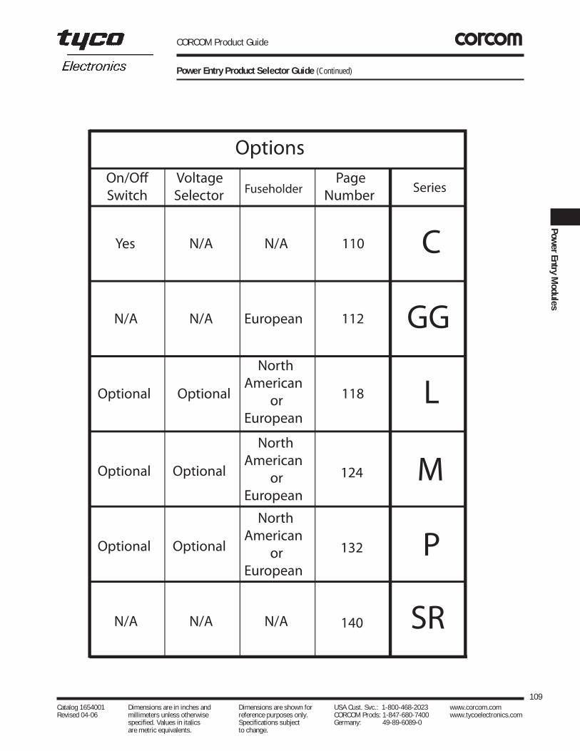
CORCOM Product Guide
Power Entry Product Selector Guide (Continued)
109Catalog 1654001 Dimensions are in inches and Dimensions are shown for USA Cust. Svc.: 1-800-468-2023 www.corcom.com Revised 04-06 millimeters unless otherwise reference purposes only. CORCOM Prods: 1-847-680-7400 www.tycoelectronics.com
specified. Values in italics Specifications subject Germany: 49-89-6089-0 are metric equivalents. to change.
PowerEntry
Modules

CORCOM Product Guide
Switch with IEC Connector Compact Size
Two function power entry module combining a DPST switchand an IEC 320 power line connector. Compact packagingallows a smaller panel cutout with choice of snap-in orflange mounting. Available with general purpose filtering (Fmodels - CFS, CFE), medical application filtering (H models- CHS, CHE) or unfiltered (CS, CE). Terminals allow for easyconnection to any wiring scheme. Preconnected terminalsfrom line to switch are available (B Models - CBS, CBE) forreducing OEM wiring time.
The medical versions (H models) are designed specificallyfor health care applications. Their extremely low leakagecurrent allows compliance with UL544 and UL2601 as wellas CSA22.2 health care specifications for use with bothpatient and non-patient care equipment. For moreinformation on UL544 or UL2601, see Appendix C.
Note: When using the models with an IEC connector,remember that the leakage current of the companion linecord, GA400, is more significant than that of the filter -which may disqualify this line cord from use in patient careapplications.
SpecificationsMaximum leakage current, each line to ground: †
F Models H Models@120 VAC 60 Hz: .25 mA 2 µA@250 VAC 50 Hz: .40 mA 5 µA
Hipot rating (one minute):line-to-ground 2250 VDCline-to-line 1450 VDC
Operating frequency: 50/60 Hz
Rated voltage: 250 VAC
Operating voltages: 115/230 VAC
Switch: Double-insulated ratedfor 10,000 operations
at full load. Amp inrush capability.
Unfiltered Push-on Force: 18 lb/80 N
Minimum insertion loss in dB:Line-to-ground in 50 ohm circuitCurrent Frequency MHzRating 0.05 0.15 0.5 1 5 10 30
F Models0 1A 10 26 46 48 46 47 460 3A 8 16 32 36 43 48 500 6A 4 11 22 27 36 41 5010A 1 4 14 18 27 33 42
H Models0 1A 16 21 37 44 26 21 100 3A 9 14 31 32 26 24 140 6A 4 10 22 23 19 18 1310A 2 6 10 15 11 11 9
Line-to-line in 50 ohm circuitCurrent Frequency MHzRating 0.05 0.15 0.5 1 5 10 30
F Models0 1A 1 3 13 28 62 67 420 3A 2 6 14 23 65 65 670 6A 2 6 14 27 46 48 5810A 1 7 14 23 42 44 62
H Models0 1A 1 6 13 29 38 42 260 3A 1 5 10 22 36 34 360 6A 1 5 14 20 31 33 3710A 1 4 11 19 32 37 38
110Catalog 1654001 Dimensions are in inches and Dimensions are shown for USA Cust. Svc.: 1-800-468-2023 www.corcom.com Revised 04-06 millimeters unless otherwise reference purposes only. CORCOM Prods: 1-847-680-7400 www.tycoelectronics.com
specified. Values in italics Specifications subject Germany: 49-89-6089-0 are metric equivalents. to change.
C Series
C Series
UL RecognizedCSA CertifiedVDE Approved CFS CS
Electrical Schematics
Resistor location for reference only.
F Models (CFS, CFE)
H Models (CHS, CHE)
LINE LOAD
LINE LOAD
B Models (CBS, CBE)
N
Power On/Off
L
G
L
G
N
Note 1: Jumpers provided on CBS and CBE versions only.
Note 2: Location of optional filter
Note 1
Note 1
Note 2
Note 2
†Applies to Filtered models only.

Case DimensionsA B C D E F
± .006 ± .006 ± .006Part No. (max) (max) (max)± .152 ± .152 ± .152
CS, CBS 1.23 .97 1.62 1.06 1.54 —31.24 24.64 41.17 26.92 39.12
CE, CBE 1.74 .97 1.62 1.06 1.54 1.41744.2 24.64 41.17 26.92 39.12 36.0
CFS, CHS 1.23 2.53 1.62 1.12 1.54 —31.24 64.26 41.17 28.5 39.12
CFE, CHE 1.74 2.53 1.62 1.12 1.54 1.41744.2 64.26 41.17 28.5 39.12 36.0
CORCOM Product Guide
Switch with IEC Connector Compact Size (Continued)
111Catalog 1654001 Dimensions are in inches and Dimensions are shown for USA Cust. Svc.: 1-800-468-2023 www.corcom.com Revised 04-06 millimeters unless otherwise reference purposes only. CORCOM Prods: 1-847-680-7400 www.tycoelectronics.com
specified. Values in italics Specifications subject Germany: 49-89-6089-0 are metric equivalents. to change.
PowerEntry
Modules
C Series
A
C
B
.2115.36
Max.
CS, CBS*
CFS, CHS
CE, CBE*
CFE, CHE
*CBS, CBE Pre-Connected Terminals
C
B
.2115.36
Max.
A
A
C
B
.2115.36
Max. F
A
C
B
.2115.36
Max.
F
1.04 26.4 Max
CBS Rear View CBE Rear ViewCBS, CBE Side View
Part Numbers
010CS1 010CE1 01CHS1 01CHE101CFS1 01CFE1 03CHS1 03CHE103CFS1 03CFE1 06CHS1 06CHE106CFS1 06CFE1 10CHS1 10CHE110CFS1 10CFE1 10CBS1 10CBE1
Recommended Panel Cutout
E
F
D R max.061.52
Panel Cutout for thickness of .031-.098 [.8-2.5]. Not recommended for plastic panels. For snap-in applica-tions, the D sides of the cutout musthave a .02 [.508] radius on the instal-lation side. Snap-in models allowfront mounting only.
Typical Dimensions:Mounting Holes: .13 [3.3] Dia. (2) with .23 Dia. x 90˚ Counter sunkTerminals: .250 [6.35] (3)Holes: .07 [1.8] Dia.
Case Styles

CORCOM Product Guide
Smallest Filtered Power Entry Modules with Metric Fuseholders
The GG series power entry modules combine the functionsof a general purpose RFI filter with an IEC power cord connector and single or dual metric fusing, in the smallestpossible panel space. A choice of .250” terminals or wireleads is available for the load-side terminations.
For maximum cost effectiveness, 6 amp models should beused for all applications rated 6 amps or less, unless thehigher performance of the 3 amp models, or the muchhigher performance of the 1 amp models, is needed.
Models with C-suffix additionally incorporate a groundchoke1 to isolate the equipment chassis from externalground at RF frequencies.
HG SeriesA medical version of our GG series, these filters offer thesame compact design but reduce the line-to-groundcapacitance in order to meet UL 2601 patient care requirements. For more information on UL2601 specification, see Appendix C.
Note: When using the models with an IEC connector,remember that the leakage current of the companion linecord, GA400, is more significant than that of the filter -which may disqualify this line cord from use in patient careapplications.
SpecificationsMaximum leakage current,each line-to-ground
HG Models GG Models@ 120 VAC 60 Hz: 2µA .25 mA@ 250 VAC 50 Hz: 5µA .42 mA
Hipot rating (one minute):line-to-ground 1550 VACline-to-line 1450 VDC
Operating frequency: 50/60 Hz
Rated voltage (max.): 250 VAC
Fuse (not included): Accepts one 5x20mm fuse(-1 models) or two 5 x 20 mm
fuses (-2 models)
Minimum insertion loss in dB:Line-to-ground in 50 ohm circuit
Current Frequency-MHzRating .01 .05 .10 .15 .5 1 5 10 30
GG/GS Models1A 12 23 29 32 41 47 50 50 553A – 10 15 19 30 36 48 50 536A – 1 4 10 16 22 36 40 50
HG Models1A 12 23 29 32 40 40 28 22 183A – 10 15 19 25 26 22 21 216A – 4 10 14 18 18 14 14 14
Line-to-line in 50 ohm circuit
Current Frequency-MHzRating .01 .15 .5 1 3 5 10 30
GG/GS Models1A 1 3 14 23 41 47 50 443A 1 2 11 14 25 38 44 406A 1 2 10 13 23 33 39 42
HG Models1A 1 3 26 35 35 35 27 203A 1 2 30 30 30 30 30 306A 1 2 30 30 30 30 30 30
112Catalog 1654001 Dimensions are in inches and Dimensions are shown for USA Cust. Svc.: 1-800-468-2023 www.corcom.com Revised 04-06 millimeters unless otherwise reference purposes only. CORCOM Prods: 1-847-680-7400 www.tycoelectronics.com
specified. Values in italics Specifications subject Germany: 49-89-6089-0 are metric equivalents. to change.
GG/HG Series
GG Series
HG1/GG1GG8
Electrical SchematicsGG/GS/HG
GG-C
LINE
Note 1
Note 2
LOAD
LINE
Note 1
Note 2
LOAD
Resistor location for reference only.Note 1: Depicts single fuse for -1 models.Note 2: For HG delete line-to-ground capacitors.CAUTION: DO NOT ATTEMPT TO OPERATE A SINGLE-FUSED MODEL WITHOUT THEFUSE DOOR IN PLACE!
UL RecognizedCSA CertifiedVDE Approved

CORCOM Product Guide
Smallest Filtered Power Entry Modules with Metric Fuseholders (Continued)
Case Styles
Case DimensionsA B C D E
± .015Part No. (max) (max) (max) (max)± .38
EGG1-1/EGG1-2/ 2.15 1.13 1.29 1.417 1.76EHG1-2 54.5 28.7 32.8 36.0 44.7EGG8-1/EGG8-2 2.02 1.13 1.29 1.417 1.76EGG1C-1/EGG1C-2 51.1 28.7 32.8 36.0 44.7EGG8C-1/EGG8C-2EGS1-1/EGS1-2 2.13 1.13 1.28 1.46* 1.42EHGS1-2 54.0 28.7 32.5 36.0 36.1*max
113Catalog 1654001 Dimensions are in inches and Dimensions are shown for USA Cust. Svc.: 1-800-468-2023 www.corcom.com Revised 04-06 millimeters unless otherwise reference purposes only. CORCOM Prods: 1-847-680-7400 www.tycoelectronics.com
specified. Values in italics Specifications subject Germany: 49-89-6089-0 are metric equivalents. to change.
PowerEntry
Modules
GG/HG Series
GG1/HG1
GG8
A
DE
C
B
EGS
B
C
A
D
E
Blue
Green/Yellow
Brown
DE
A
B
C
.615.2
Recommended Panel Cutouts
1.1429.0
1.41736.0
1.3033.0
GG / HGFront or Back Mount
GS / HGSFront Mount Only
1.2431.5
1.2932.8
Typical dimensions:Terminals: .250 [6.35] (3) Holes: .07 [1.8] Dia.Mounting Holes: .126 [3.20] Dia. (2)
Typical dimensions:Wire leads: 5.0 [127.0] Min. 18 AWG Mounting Holes: .126 [3.20] Dia. (2)
Part Number1 RFI Filter Type2 Current Rating3 Metric Fuseholders Load Side Terminations1EGG1-1 General Purpose2 1 1 .250 [6.35] Terminals (3)1EGG1-2 General Purpose 1 2 .250 [6.35] Terminals (3)1EGG8-1 General Purpose 1 1 5.0 [127.0] Wire Leads1EGG8-2 General Purpose 1 2 5.0 [127.0] Wire Leads1EGS1-1 General Purpose 1 1 .250 [6.35] Terminals (3)1EGS1-2 General Purpose 1 2 .250 [6.35] Terminals (3)3EGG1-1 General Purpose 3 1 .250 [6.35] Terminals (3)3EGG1-2 General Purpose 3 2 .250 [6.35] Terminals (3)3EGG8-1 General Purpose 3 1 5.0 [127.0] Wire Leads3EGG8-2 General Purpose 3 2 5.0 [127.0] Wire Leads3EGS1-1 General Purpose 3 1 .250 [6.35] Terminals (3)3EGS1-2 General Purpose 3 2 .250 [6.35] Terminals (3)6EGG1-1 General Purpose 6 1 .250 [6.35] Terminals (3)6EGG1-2 General Purpose 6 2 .250 [6.35] Terminals (3)6EGG8-1 General Purpose 6 1 5.0 [127.0] Wire Leads6EGG8-2 General Purpose 6 2 5.0 [127.0] Wire Leads6EGS1-1 General Purpose 6 1 .250 [6.35] Terminals (3)6EGS1-2 General Purpose 6 2 .250 [6.35] Terminals (3)1EHG1-2 Medical 1 2 .250 [6.35] Terminals (3)3EHG1-2 Medical 3 2 .250 [6.35] Terminals (3)6EHG1-2 Medical 6 2 .250 [6.35] Terminals (3)
1EHGS1-2 Medical 1 2 .250 [6.35] Terminals (3)3EHGS1-2 Medical 3 2 .250 [6.35] Terminals (3)6EHGS1-2 Medical 6 2 .250 [6.35] Terminals (3)
1 Ground choke available on general purpose models. Add suffix "C" (1EGG1C-1). Does not include EGS models.2 General purpose filter for susceptibility applications. 3 Current rating @120 VAC and 250 VAC.
for panel thickness.032-.080 [.81-2.03]Radius: 0.138[0.35]

CORCOM Product Guide
Voltage Selecting and Fused Connector with Optional RFI Power Line Filter for General Purpose Applications for UL544 Health Care Equipment
The most widely accepted of all the power entry modules,the J series combines an IEC connector, 2-voltage, or 4-voltage selection, and a North American fuseholder. Itfeatures a compact snap-in design and a unique voltageselector card.
J4 Models - This general purpose filter providessusceptibility protection from line-to-ground noise on thepower line and acts as a high frequency “clean-up” filter formore complex emissions applications.
HJ4 Models - This medical filter provides susceptibilityprotection without the leakage current associated with line-to-ground capacitors. Designed to allow equipment tomeet UL544 medical specifications for patient care andnon-patient care equipment, the HJ filter has a maximumleakage current of 2µA at 120 VAC 60 Hz. See Appendix C for more information on medical applications and ULstandards.
Equipment rating labels and mounting clips for thickerpanel widths are available as accessories.
For more information on UL544 specifications, seeAppendix C.
Note: When using the models with an IEC connector,remember that the leakage current of the companion linecord, GA400, is more significant than that of the filter -which may disqualify this line cord from use in patient careapplications.
114Catalog 1654001 Dimensions are in inches and Dimensions are shown for USA Cust. Svc.: 1-800-468-2023 www.corcom.com Revised 04-06 millimeters unless otherwise reference purposes only. CORCOM Prods: 1-847-680-7400 www.tycoelectronics.com
specified. Values in italics Specifications subject Germany: 49-89-6089-0 are metric equivalents. to change.
J Series
J Series
UL RecognizedCSA Certified
6J4/6J4-2Terminal View
Front View, All Models
6HJ4-1/6HJ4-2Terminal View
Voltage SelectionUnfiltered and Filtered Models
Open cover door and rotate fuse-pull lever to left. Selectoperating voltage by orienting voltage selection card,desired voltage on top left side. Push card firmly into module slot. Rotate fuse-pull lever back into normal position and re-insert fuse into holders. Use caution inselecting correct fuse value.
Unfiltered ModelsAvailable Voltage Selection
Part Number Positions6VJ1 4
6VJ1-2 2
Unfiltered ModelsAvailable Voltage
Part Number Selection RFI FilterPositions Type
6VJ4 4 General Purpose1
6J4-2 2 General Purpose1
6HJ4-4 4 Medical2
6HJ4-2 2 Medical2
Note 1: General purpose filter for susceptibility applications
Note 2: Medical line filter for very low leakage UL544 health care requirements

CORCOM Product Guide
Specifications
6J4 6EHJ4 6VJModels Models Models
@250 VAC 50 Hz: 500 µA 5 µA 5 µA
Hipot rating (one minute):line-to-ground 2250 2250 1550line-to-line 1450 1450 1450
Operating frequency: 50/60 HzOperating voltages:
6VJ1, 6J4, 6HJ4-4: 100, 120, 220, 240 VAC 6J1-2, 6J4-2, 6HJ4-2: 115, 230 VAC
Rated current: 6A
Fuse (not included): Integral fuseholder, lineside,accepts .25" x 1.25" fuse
Terminals: Connector block terminals .045" square, suitable for soldering, wire wrapping,
or crimp-on lugs
115Catalog 1654001 Dimensions are in inches and Dimensions are shown for USA Cust. Svc.: 1-800-468-2023 www.corcom.com Revised 04-06 millimeters unless otherwise reference purposes only. CORCOM Prods: 1-847-680-7400 www.tycoelectronics.com
specified. Values in italics Specifications subject Germany: 49-89-6089-0 are metric equivalents. to change.
PowerEntry
Modules
J Series
Voltage Selecting and Fused Connector with Optional RFI Power Line Filter for General Purpose Applications for UL544 Health Care Equipment (Continued)
Minimum insertion loss in dB:
Line-to-ground in 50 ohm circuit
Current Frequency-MHzRating .15 .5 1 5 10 20 30
J4 Models6A 9 20 25 41 45 45 48
HJ4 Models6A 9 11 15 19 13 12 10
Electrical Schematics
Filtered 6J4 & 6J4-2
Hot
Neutral
Note 1
Pilotlight
Transformerprimary
100V120V
100V
20V
120V
220V240V
A A
B B
C C
D D
E E
FJH F
Power On-OffOff
OnGround
Note 3
Filtered 6HJ4-4 & 6HJ4-2
Hot
Neutral
Note 1
Pilotlight
Transformerprimary
100V120V
100V
20V
120V
220V240V
A A
B B
C C
D D
E E
FJH F
Power On-OffOff
OnGround
Note 3
Note 1: Jumper required if only SPST power switch is used. Note 2: Jumpers required if no input filtering is used. Note 3: Use only 120V and 240V positions for 2-volt selection units.
Electrical Schematics

CORCOM Product Guide
116Catalog 1654001 Dimensions are in inches and Dimensions are shown for USA Cust. Svc.: 1-800-468-2023 www.corcom.com Revised 04-06 millimeters unless otherwise reference purposes only. CORCOM Prods: 1-847-680-7400 www.tycoelectronics.com
specified. Values in italics Specifications subject Germany: 49-89-6089-0 are metric equivalents. to change.
J Series
Voltage Selecting and Fused Connector with Optional RFI Power Line Filter for General Purpose Applications for UL544 Health Care Equipment (Continued)
Case Styles
Recommended Panel CutoutUnfiltered and Filtered Models
Unfiltered Models
Filtered Models
*±.003Note 4: Fuse cover door shown in open condition.Note 5: Standard units mount in panel thickness of .060 - .090"
Special mounting clips sold separately for panel thickness of .105-.125".See Accessories List on next page.
Case Dimensions
Part No. A B C D(max) (max) (max) (max)
Unfiltered 2.68 1.52 1.17 1.236VJ1/6VJ1-2 68.1 38.6 29.7 31.2Filtered 2.75 1.87 1.17 1.586J4/6J4-2 69.9 47.5 29.7 40.1
6HJ4-4/6HJ4-2 2.75 1.87 1.17 1.5869.9 47.5 29.7 40.1
A
C
BD
Note 5.110 [2.79]Terminals
A
Note 5
.110 [2.79]Terminals
C
BD
Note 4
Bezel 2.60*66.0
2.6868.13.0076.2
1.063*27.0
1.1729.7
Mounting diagram(Clearance)

Equipment Rating LabelsUnfiltered and Filtered Models
Self-adhesive labels, as shown below, are available inmultiples of 40. Specify part number.
CORCOM Product Guide
AccessoriesUnfiltered and Filtered Models
Line Cord No. GA400:(7 1/2 foot, 3-conductor line cord to mate with J series)
JA302, 2 Voltage Selector Card(comes standard with 6VJ1-2, 6J4-2, 6HJ4-2)
JA304, 4 Voltage Selector Card(comes standard with 6VJ1, 6J4, 6HJ4-4)
JA403, Mounting Clips for .105-.125" Panel
JA500, Voltage Selector Card Extractor Tool
117Catalog 1654001 Dimensions are in inches and Dimensions are shown for USA Cust. Svc.: 1-800-468-2023 www.corcom.com Revised 04-06 millimeters unless otherwise reference purposes only. CORCOM Prods: 1-847-680-7400 www.tycoelectronics.com
specified. Values in italics Specifications subject Germany: 49-89-6089-0 are metric equivalents. to change.
PowerEntry
Modules
J Series
Voltage Selecting and Fused Connector with Optional RFI Power Line Filter for General Purpose Applications for UL544 Health Care Equipment (Continued)
CCBBAA
2.330
.210Line V. + 5 - 10%
48-440 - 50 VA Max. Fuse100V 120V 220V 240V
500mA 250mA4-Volt
Part A B C
Number VA Fuse FuseMax. 100/120 (115) 220/240 (230)
JA410 25 250 mA 125 mAJA411 50 500 mA 250 mAJA412 100 1A 500 mAJA413 200 2A 1AJA414 250 2.5A 1.25AJA415 300 3A 1.5AJA416 400 4 A 2AJA417 500 5A 2.5AJA418 600 6A 3AJA419 Assortment
Labels - 40 of one part numberLabels - 5 each of 8 part numbers for 4-volt

CORCOM Product Guide
Power Entry Module with RFI Power Line Filter for General or Medical Applications
The L series power entry modules are compact units thatcombine a multi-function power entry module and high per-formance RFI filtering capabilities. They are available witheither a four-voltage selector or a DPST on/off switch. Bothvariations can be specified with North American orEuropean fusing capabilities and are available in eitherflange or snap-in mounting.
These filters are UL recognized, CSA certified, and VDEapproved. The L series modules offer a choice of filters forgeneral or medical applications.
EDL Models
The RFI filter is for general purpose applications where line-to-line and line-to-ground noise must be controlled.The filter is designed to meet the very low leakage requirements of VDE portable equipment. They are available in three current ratings.
EHL Models
This medical filter provides susceptibility protection without the leakage current associated with line-to-groundcapacitors. Designed to allow equipment to meet UL544for patient care and non-patient care equipment, the EHLfilter has a maximum leakage current of 2 µA at 120 VAC60 Hz. See Appendix C for more information on medicalapplications and UL standards.
Note: When using the models with an IEC connector,remember that the leakage current of the companion linecord, GA400, is more significant than that of the filter -which may disqualify this line cord from use in patient careapplications.
118Catalog 1654001 Dimensions are in inches and Dimensions are shown for USA Cust. Svc.: 1-800-468-2023 www.corcom.com Revised 04-06 millimeters unless otherwise reference purposes only. CORCOM Prods: 1-847-680-7400 www.tycoelectronics.com
specified. Values in italics Specifications subject Germany: 49-89-6089-0 are metric equivalents. to change.
L Series
L Series
UL RecognizedCSA CertifiedVDE Approved
EDL1S/EHL1S
EDL4C/EHL4C
Voltage Selection
To change selected voltage: disconnect the power cord;open cover using a small blade screwdriver or similar tool;insert the tool into the voltage selection slot and removewheel from unit; select desired voltage; replace wheel intounit and close cover, making sure the selected voltageappears in connector window.
Voltage selection
slot
4-Voltageselection
wheel
Cover
Fuseholder
Note: All models have North American or dual European fusing capability and are available in either flange or snap-in mounting.

CORCOM Product Guide
119Catalog 1654001 Dimensions are in inches and Dimensions are shown for USA Cust. Svc.: 1-800-468-2023 www.corcom.com Revised 04-06 millimeters unless otherwise reference purposes only. CORCOM Prods: 1-847-680-7400 www.tycoelectronics.com
specified. Values in italics Specifications subject Germany: 49-89-6089-0 are metric equivalents. to change.
PowerEntry
Modules
L Series
Power Entry Module with RFI Power Line Filter for General or Medical Applications (Continued)
Hot
NeutralNote 1 H
Ground
G
On/Off
2(1)
1(1a)
(2)4
(2a)3
Note 2
Device
Cutomer
Transformer
Primaries
Electrical Schematics
DL Models (with switch)
Hot
Neutral
Note 1 G
Ground
H
On/OffNote 2
Customer
Transformer
Primaries100V120V
100V
20V
120V
220V240V
A A
B B
C C
D D
E E
F F
A
B
C
D
E
F
HL Models (with 4-voltage selection)
Hot
Neutral
Note 1 G
Ground
H
On/OffNote 2
Cutomer
Transformer
Primaries100V120V
100V
20V
120V
220V240V
A A
B B
C C
D D
E E
F F
A
B
C
D
E
F
DL Models (with 4-voltage selection)
Note 1: Provision for dual European style fusing. Note 2: On/Off switch present only with "S" suffix.Resistor location for reference only.
Hot
NeutralNote 1 H
Ground
G
On/Off
2(1)
1(1a)
(2)4
(2a)3
Note 2
Device
Customer
Transformer
Primaries
HL Models (with switch)
Specifications
Maximum leakage current, each line-to-ground:
EDL EHL UnfilteredModels Models Models
@120 VAC 60 Hz: 0.25 mA 2 µA N/A@250 VAC 50 Hz: 0.50 mA 5 µA N/A
Hipot rating (one minute):line-to-ground 1500 1500 N/Aline-to-line 1450 1450 N/A
Operating frequency: 50/60 HzOperating voltages:
1s& 1SC Suffix (fixed): 250 VAC Max. 4 & 4C Suffix (selectable): 100, 120, 220, 240 VAC
Rated current:
2EDL & 2EHL 6A4EDL & 4EHL 4A6EL, 6EDL & 6EHL 6A
Switch: Double-insulated, ratedfor 10,000 operations at full
load. 51 Amp inrush capability.
Fuse (not included): Accepts one .25" x 1.25" fuse or two 5 x 20 mm fuses
Terminals: 110 [2.79] except for switch.187 [4.8] for switch
Minimum insertion loss in dB:
Line-to-ground in 50 ohm circuitCurrent Frequency-MHzRating .05 .15 1 5 10 30
EDL Models2A 6 14 24 40 45 504A 2 8 18 32 38 456A 1 6 17 31 37 45
EHL Models06A 3 8 15 18 18 18
Line-to-line in 50 ohm circuit
Current Frequency-MHzRating .05 .5 1 3 5 10 30
EDL Models2A 7 16 21 23 37 47 504A 6 14 18 23 26 45 476A 6 15 20 25 24 45 50
EHL Models06A 4 14 20 28 32 38 42

CORCOM Product Guide
Case Dimensions
A B C D E FPart No. (max) ±.015 (max) (max) (max) (max)
±.381
Flange 1.98 1.575 2.3 2.14 1.66 1.11Unfiltered 50.29 40.0 58.42 54.36 42.16 28.19Snap-in 1.28 — 2.3 2.14 1.66 1.11Unfiltered 32.51 58.42 54.36 42.16 28.19
Flange 1.98 1.575 2.3 2.14 2.01 1.11Filtered 50.29 40.0 58.42 54.36 51.05 28.19
Snap-in 1.28 — 2.3 2.14 2.01 1.11Filtered 32.51 58.42 54.36 51.05 28.19
120Catalog 1654001 Dimensions are in inches and Dimensions are shown for USA Cust. Svc.: 1-800-468-2023 www.corcom.com Revised 04-06 millimeters unless otherwise reference purposes only. CORCOM Prods: 1-847-680-7400 www.tycoelectronics.com
specified. Values in italics Specifications subject Germany: 49-89-6089-0 are metric equivalents. to change.
L Series
Power Entry Module with RFI Power Line Filter for General or Medical Applications (Continued)
Case Styles — Unfiltered ModelsFlange Models
Typical dimensions:Mounting Holes: .126 [3.20] Dia. (2)All backplate terminals: .110 [2.79] terminals, except for switch. Switch terminals are .187 [4.765] Note: Snap-in models allow front mounting only.
(1) For panel thickness of .031-.079 [0.8-2.0](2) For panel thickness of .083-.126 [2.1-3.2](3) For snap-in application, the 1.22 [28.5] sides of the cutout must have a .02 [.508] radius onthe installation side. All backplate terminals: .110 [2.79] terminals, except for switch. Switch terminals are .187 [4.75]Note: Snap-in models allow front mounting only.
G H
3
1
4
2
BA E.221
5.61
F
C D
.06 1.52
R
2.201 55.91
2.21356.21
1.12228.501.57540.00
.020
.508R
*
*
*
* +.008, -.00+.203 -.00
Snap-In Models
A C E
B D F
A
G H
E.2215.61
F
C D
.06 1.52
R
2.201 55.91
2.21356.21
1.12228.50
.020
.508R
*
*
*
* +.008, -.00+.203 -.00
(1)
(2)
Back View
Side View
Back View
Recommended Panel Cutout
Recommended Panel Cutout
Side View
Snap-In Models
Case Styles — Filtered Models
A C E
B D F
G H
Snap-in version
D
E.2215.61
C
G H
2
43
1
Flange mounted versionFlange mounted version
.2215.61
D
E
C
Side View
Side View
Note: Metric fuse models have additional jumper from filter-to-module.
Flange Models

CORCOM Product Guide
121Catalog 1654001 Dimensions are in inches and Dimensions are shown for USA Cust. Svc.: 1-800-468-2023 www.corcom.com Revised 04-06 millimeters unless otherwise reference purposes only. CORCOM Prods: 1-847-680-7400 www.tycoelectronics.com
specified. Values in italics Specifications subject Germany: 49-89-6089-0 are metric equivalents. to change.
PowerEntry
Modules
L Series
Power Entry Module with RFI Power Line Filter for General or Medical Applications (Continued)
UNFILTERED MODELSPart Current Available Voltage DPST Mounting Fuseholder
Number Rating Selection On/Off Style TypePosition Switch
6EL1S 6A 1 •• Flange North American6EL1SC 6A 1 •• Snap-In North American6EL1SM 6A 1 •• Flange Metric
6EL1SCM 6A 1 •• Snap-In Metric6EL4 6A 4 Flange North American
6EL4C 6A 4 Snap-In North American6EL4M 6A 4 Flange Metric
6EL4CM 6A 4 Snap-in Metric
FILTERED MODELSPart Filter Current Available Voltage DPST Mounting Fuseholder
Number Type Rating Selection On/Off Style TypePosition Switch
2EDL1S Linear 2A 1 •• Flange North American2EDL1SC Linear 2A 1 •• Snap-In North American2EDL1SM Linear 2A 1 •• Flange Metric
2EDL1SCM Linear 2A 1 •• Snap-In Metric2EDL4 Linear 2A 4 Flange North American
2EDL4C Linear 2A 4 Snap-In North American2EDL4M Linear 2A 4 Flange Metric
2EDL4CM Linear 2A 4 Snap-in Metric4EDL1S Linear 4A 1 •• Flange North American
4EDL1SC Linear 4A 1 •• Snap-in North American4EDL1SM Linear 4A 1 •• Flange Metric
4EDL1SCM Linear 4A 1 •• Snap-in Metric4EDL4 Linear 4A 4 Flange North American
4EDL4C Linear 4A 4 Snap-in North American4EDL4M Linear 4A 4 Flange Metric
4EDL4CM Linear 4A 4 Snap-in Metric6EDL1S Linear 6A 1 •• Flange North American
6EDL1SC Linear 6 1 •• Flange North American6EDL1SM Linear 6 1 •• Flange Metric
6EDL1SCM Linear 6 1 •• Snap-in Metric6EDL4 Linear 6 4 Flange North American
6EDL4C Linear 6 4 Snap-in North American6EDL4M Linear 6 4 Flange Metric
6EDL4CM Linear 6 4 Snap-in Metric6EHL1S Medical 6 1 •• Flange North American
6EHL1SC Medical 6 1 •• Snap-in North American6EHL1SM Medical 6 1 •• Flange Metric
6EHL1SCM Medical 6 1 •• Snap-in Metric6EHL4 Medical 6 4 Flange North American
6EHL4C Medical 6 4 Snap-in North American6EHL4M Medical 6 4 Flange Metric
6EHL4CM Medical 6 4 Snap-in Metric
•• Includes DPST switch

Specifications
Maximum leakage current, each line-to-ground:@ 120 VAC 60 Hz: FLA Model 0.25 mA
XLA/ZLA Models 0.30 mA
@ 250 VAC 50 Hz: All Models 0.50 mA
Hipot rating (one minute): line-to-ground 1500 VACline-to-line 1450 VDC
Operating voltages: 110,120, 220/240 VAC
Operating frequency: 50/60 Hz
Rated voltage (max.): 250 VAC
Switch: Double-insulated, rated for50,000 operations at full load.
35 Amp inrush capability
Fuse (not included): Accepts one 1/4" x 1-1/4" fuse, or two 5 x 20 mm fuses
Terminals: .110 [2.79] terminals
Minimum insertion loss in dB:
CORCOM Product Guide
Multi-Function Power Entry Modules with RFI Power Line Filters
The LA series is a multi-function power entry connector witha choice of filtering capabilities. The series features an IECpower line connector, selectable North American or dualEuropean fusing capabilities, DPST on/off switch, and120/240 voltage selection. The filtered LA units provide aone piece solution to power entry needs and provide a filtering solution for almost any RFI problem. Their verticaldesign is flange mounted.
This series offers three levels of filtering, all carrying ULrecognition, CSA certification, and VDE approval.
FLA Model – General purpose RFI filter designed for sus-ceptibility applications, effectively providing RFI control ofline-to-ground noise.
XLA Model – High performance RFI filter designed to bringmost digital equipment (including switching power sup-plies) into compliance with FCC Part 15J, Class B conduct-ed emissions limits.
ZLA Model – Premium performance RFI filter designed tobring most digital equipment (including switching powersupplies) into compliance with EN55022, Level B (as wellas FCC Part 15J, Class B) conducted emissions limits.
122Catalog 1654001 Dimensions are in inches and Dimensions are shown for USA Cust. Svc.: 1-800-468-2023 www.corcom.com Revised 04-06 millimeters unless otherwise reference purposes only. CORCOM Prods: 1-847-680-7400 www.tycoelectronics.com
specified. Values in italics Specifications subject Germany: 49-89-6089-0 are metric equivalents. to change.
LA Series
LA Series
UL RecognizedCSA CertifiedVDE Approved
FLA/XLA/ZLA
Voltage Selection
To change selected voltage: remove the fuse cartridgeusing a small blade screwdriver or similar tool; select thedesired voltage by matching the arrow on the fuse car-tridge to the arrow located on the front of the unit (lowerright corner); replace the fuse cartridge making sure thevoltage selection arrow aligns with the arrow located on the front of the unit.
Fuse Changing
Remove the fuse cartridge using a small blade screwdriveror similar tool; for European fusing pull out the sliding fusecovers located at the top of each fuse compartment; insertdesired fuses; push the sliding fuse covers back in placeand insert the fuse cartridge back into the unit making surethe voltage selection arrow aligns with the arrow located onthe front of the unit. (Note: Single North American orEuropean fuse placement is always on the side of thedesired voltage selection arrow behind the fuse symbol;the other compartment may be used as a spare or be leftblank. Dual European fusing capability is available for220/240 volts only.)
Line-to-ground in 50 ohm circuitCurrent Frequency-MHzRating .01 .05 .15 .5 1 5 10 30
FLA5A - - 14 21 26 40 46 50
XLA3A 2 12 21 35 46 44 44 40
ZLA3A 14 28 38 42 40 40 40 40
Line-to-line in 50 ohm circuit
Current Frequency-MHzRating .02 .03 .05 .07 .15 .5 1 5 10 30
XLA3A - - - 5 33 60 65 60 50 50
ZLA3A 3 14 29 38 57 72 72 65 55 50

Electrical Schematics
CORCOM Product Guide
Multi-Function Power Entry Modules with RFI Power Line Filters (Continued)
123Catalog 1654001 Dimensions are in inches and Dimensions are shown for USA Cust. Svc.: 1-800-468-2023 www.corcom.com Revised 04-06 millimeters unless otherwise reference purposes only. CORCOM Prods: 1-847-680-7400 www.tycoelectronics.com
specified. Values in italics Specifications subject Germany: 49-89-6089-0 are metric equivalents. to change.
Power Entry M
odules
LA Series
FLA
XLA & ZLA
Power on/off
Neutral
Ground
Phase
CustomerTransformerPrimaries
A
B
C
D
E
F
G
120V 240V
D E F
A B C
A
B
D
E
F
A or D
120V
120V
D E F
A B C
On/Off
Neutral
Hot
CustomerTransformerPrimaries
A
B
C
D
E
F
G
120V 240V
A
B
D
E
F
A or D
120V
120V
Note: Provision for dual European fusing by connection to "A".Resistor location for reference only.
Electrical Schematics
Case Style FLA, XLA & ZLA
FB
110-120
220-240
A
E
DC
Typical dimensions:Terminals: .110 [4.80]Holes: .059 [1.5] Dia. Max., except solder lug ground tap with wire wrap.Mounting Holes: .142 [3.6] Dia. (2)
Case Dimensions
A B C D E FPart No. (max) ±0.15 (max) (max) (max) (max)
±0.381
5EFLA2S 1.99 1.57 2.59 2.41 3.16 1.1850.5 39.9 65.79 61.21 68.07 29.97
3EXLA2S 1.99 1.57 2.59 2.41 4.16 1.1850.5 39.9 65.79 61.21 105.7 29.97
3EZLA2S 1.99 1.57 2.59 2.41 4.16 1.1850.5 39.9 65.79 61.21 105.7 29.97
Recommended Panel CutoutFL, XLA & ZLA
Note: All models allow front mounting only.
2.42*61.47
1.19*30.23
.093 2.36
R
.1403.56
+.020 - .00+ 0.5 - .00
Dia. (2)
1.5739.88
*
Part Numbers
0 5EFLA2S3EXLA2S3EZLA2S

CORCOM Product Guide
124Catalog 1654001 Dimensions are in inches and Dimensions are shown for USA Cust. Svc.: 1-800-468-2023 www.corcom.com Revised 04-06 millimeters unless otherwise reference purposes only. CORCOM Prods: 1-847-680-7400 www.tycoelectronics.com
specified. Values in italics Specifications subject Germany: 49-89-6089-0 are metric equivalents. to change.
M Series
M SeriesThe M series power entry modules offer the most choicesof power entry components and filtering options to fit a specific need. The fully configured M series expands theoptions of a manufacturer whose products are marketedworldwide. One component, fully assembled and tested,provides the capability of interfacing a multi-voltage powersupply to any common voltage or fusing scheme in theworld, without modification.
•The IEC connector provides an internationally accepted power entry termination, which can be used with a varietyof line cords.
•The selectable fuseholder allows use of single or dualEuropean fuses, or a single North American fuse.
•The optional DPST on/off switch breaks both sides of theline and is labeled with the international I/O markings.
•The optional voltage selector provides a convenientmeans to change transformer primary connection, and it is available in both 2-voltage and 4-voltage configurations.
•The series is available with four filter circuits to meet avariety of applications, and convenient connections areprovided on unfiltered models to allow wiring of a separate RFI filter.
The M series is a family of components offering greaterflexibility and cost-effectiveness in the selection of primary power components. Wiring to the modules is accom-plished via .110” terminals for labor savings and convenience.
Four filter circuits provide a choice of attenuation tailored tospecific categories of susceptibility and emissions needs.
HM Models – This medical filter provides susceptibility protection without the leakage current associated with line-to-ground capacitors. Designed to allow equipment to meet UL544 for patient care and non-patient care equipment, the HM filter has a maximum leakage current of 2 µA at 120 VAC 60 Hz. See Appendix C for more information on medical applications and UL standards.
FM Models – General purpose RFI filter designed for sus-ceptibility applications, effectively providing RFI control ofline-to-ground noise. The design is compact and meetsthe very low leakage current requirements of VDE portableequipment as well as (120 Volt) UL544 non-patient medicalequipment.
XM Models – High performance RFI filter designed to bringmost digital equipment (including switching powersupplies) into compliance with FCC Part 15J, Class Bconducted emissions limits.
ZM Models – Premium RFI filter designed to bring mostdigital equipment (including switching power supplies) intocompliance with EN55022, Level B (as well as FCC Part15J, Class B) conducted emissions limits.
XM/ZM
VM
Power Entry Module with Optional RFI Power Line Filters for General andMedical Applications
UL RecognizedCSA CertifiedVDE Approved
Fuse Installation Instructions
1. Remove power cord.2. Pry door open at socket.3. Lift and swing door into socket.4. Lift fuse holder out of housing.5. Install one (1) AG fuse or two (2) metric fuses*.6. Replace fuse holder into housing.7. Swing and snap door back in place.
*Install fuses on one side only, do not install both AG and metric fuses at thesame time.

CORCOM Product Guide
125Catalog 1654001 Dimensions are in inches and Dimensions are shown for USA Cust. Svc.: 1-800-468-2023 www.corcom.com Revised 04-06 millimeters unless otherwise reference purposes only. CORCOM Prods: 1-847-680-7400 www.tycoelectronics.com
specified. Values in italics Specifications subject Germany: 49-89-6089-0 are metric equivalents. to change.
Power Entry M
odules
M SeriesFuse ChangingEuropean Fusing Arrangement**
North American Fusing Arrangement**
Power Entry Module with Optional RFI Power Line Filters for General andMedical Applications (Continued)
**Install fuses on one side only. Do Not install both AG and Metric fuses atthe same time.
Voltage SelectionTo change selected voltage: open cover, using small blade screwdriver or similar tool; set aside cover/fuse block assembly; pull voltage selector card straight out ofhousing, using indicator pin; orient selector card so thatdesired voltage is readable at the bottom; orient indicatorpin to point up when desired voltage is readable at bottom(note that when indicator pin is fixed, successive voltagesare selected by rotating the card 90° clockwise); insert voltage selector card into housing, printed side of card facing forward toward IEC connector and edge containingthe desired voltage first; replace cover, and verify thatindicator pin shows the desired voltage.
Voltage Selector Card Orientation
00
00
22
22
22
11
11
44
33
00
00
00
00
4422
22
11
33
0000
00
00
22
22
11
11
44
33
00
00
00 00
22
22
2211
44
33
100V 120V
230V 240V
00
22
00
00
11
Removing the Fuse Holder
A
A
Section A-A
"X"
Lift Up
1. Insert a pocket screwdriver at point “X” as shown.
Gently lift UP until the entire door lifts up approximately 1/4" (minimum).
2. Once lifted, the door will pivot on it’s hinges and expose the fuse holder.
3. When the fuse holder is installed in the single fuse position, apply the screwdriver as shown and gently pry up.
When the fuse holder is installed in the dual fuse position, it will normally release as soon as the door is opened.

CORCOM Product Guide
126Catalog 1654001 Dimensions are in inches and Dimensions are shown for USA Cust. Svc.: 1-800-468-2023 www.corcom.com Revised 04-06 millimeters unless otherwise reference purposes only. CORCOM Prods: 1-847-680-7400 www.tycoelectronics.com
specified. Values in italics Specifications subject Germany: 49-89-6089-0 are metric equivalents. to change.
M Series
Power Entry Module with Optional RFI Power Line Filters for General andMedical Applications (Continued)
Electrical Schematics – Unfiltered ModelsVM (1-Voltage)
K
L
GG
Neutral
Hot
Power On/OffNote 3
Note 2
Customer Transformer Primaries
L
K
120V
VM (2-Voltage)
B
D
E
F
A
C
D
E
F
H B
J
G
Neutral
Hot
Power On/OffNote 3
Note 2 Note 1
Note 1 Note 4
120V 240V
Customer Transformer Primaries
LL
KK
C
F
A
120V
120V
120V
120V
VM (4-Voltage)
A
C
D
E
F
A
C
D
E
F
H B
J
G
Neutral
Hot
Power On/OffNote 3
Note 2 Note 1
Note 1
120V100V
230V240V
Customer Transformer Primaries
L
K
20V
100V
120V
Note 1: Jumpers required if no input filter is used. Note 2: Provision for dual European style fusing.Note 3: On/off switch present only with "S" suffix.Note 4: When using a center-tapped transformer, the C-F winding should
be the low voltage (high current) winding and must be capable ofhandling the full primary current in the 120V position.
SpecificationsMaximum leakage current,each line-to-ground
HM FM XM/ZM@ 120 VAC 60 Hz: 2µA .25 mA .30 mA@ 250 VAC 50 Hz: 5µA .50 mA .50 mA
Hipot rating (one minute):line-to-ground: 1500 VACline-to-line 1450 VDCline-to-load (switch off) Unfiltered only 2500 VAC
Operating frequency: 50/60 Hz
Rated voltage (max.): 250 VAC
Operating voltages: 100, 120, 220/ 240 VAC
Switch: Double-insulated, rated for100,000 operations at full load
at 70 Amps inrush current.
Fuse (not included): Reversible fuseholder, acceptsone 1/4" x 1-1/4" fuse
or two 5 x 20 mm fuses
Terminals: .110 [2.79] terminals
Minimum insertion loss in dB:
Line-to-ground in 50 ohm circuit
Current Frequency-MHzRating .01 .05 .15 .5 1 5 10 30
HM5A - - 14 18 19 22 22 17
FM05A - - 14 21 26 40 45 40
XM3A 2 13 23 40 46 44 44 44
ZM3A 15 29 39 46 43 40 40 40
Line-to-line in 50 ohm circuit
Current Frequency-MHzRating .02 .03 .05 .07 .15 .5 1 5 10 30
XM03A - - - 5 34 62 68 60 50 40
ZM3A 5 13 28 37 55 75 75 62 54 44

CORCOM Product Guide
127Catalog 1654001 Dimensions are in inches and Dimensions are shown for USA Cust. Svc.: 1-800-468-2023 www.corcom.com Revised 04-06 millimeters unless otherwise reference purposes only. CORCOM Prods: 1-847-680-7400 www.tycoelectronics.com
specified. Values in italics Specifications subject Germany: 49-89-6089-0 are metric equivalents. to change.
Power Entry M
odules
M Series
Power Entry Module with Optional RFI Power Line Filters for General andMedical Applications (Continued)
Electrical Schematics - Filtered Models
FM & HM (1-Voltage)
FM & HM (4-Voltage)
Customer Transformer Primaries
Neutral
Phase
Power On/Off
Note 4
Note 4
Note 3
Note 2Note 1
120V100V
230V240V
A
C
D
E
F
A
C
D
E
F
H B
J
G
KK
L
20V
100V
120V
XM & ZM (1-Voltage)
XM & ZM (4-Voltage)
Neutral
Phase
Power On/Off
Note 2
Note 1H B
J F
G
Neutral
Phase
Power On/Off
Note 1
Note 2 Note 4
Note 4
120V100V
230V240V
A
C
D
E
F
A
C
D
E
F
H B
J
G
20V
100V
120V
K
L
Customer Transformer Primaries
Neutral
Phase
Power On/Off
Note 2
Note 3
Note 1H B
J F
G
Recommended Panel Cutout (Snap-In Only)
Case Styles – Unfiltered Models6VM1 (IEC Connector, Selectable Fuseholder)
C
E
USE ONLY WITH250V FUSES
DISCONNECT POWERBEFORE REPLACING FUSES
D
B
A
6VM1C (IEC Connector, Selectable Fuseholder, Snap-in)
C
EAD
USE ONLY WITH250V FUSES
DISCONNECT POWERBEFORE REPLACING FUSES
6VM1S (IEC Connector, DPST On/Off Switch, SelectableFuseholder)
C
E
USE ONLY WITH250V FUSES
DISCONNECT POWERBEFORE REPLACING FUSES
D
B
A
6VM1SC (IEC Connector, DPST On/Off Switch,Selectable Fuseholder, Snap-In)
C
EAD
USE ONLY WITH250V FUSES
DISCONNECT POWERBEFORE REPLACING FUSES
F
0.13 R3.30
1.14529.08
Typical dimensions:Mounting Holes: .155 [3.94] Dia. (2) with .279 [7.09] Dia. x 82˚ Countersunk.All mounting holes countersunk. Panel Thickness: .06 - .09 [1.53 -2.29]
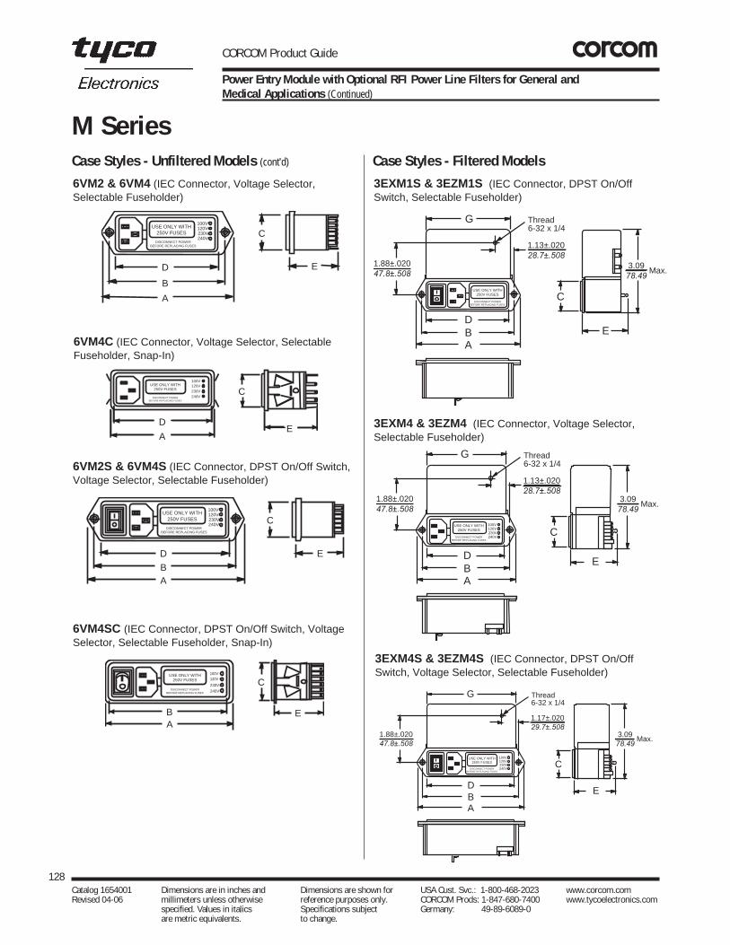
CORCOM Product Guide
128Catalog 1654001 Dimensions are in inches and Dimensions are shown for USA Cust. Svc.: 1-800-468-2023 www.corcom.com Revised 04-06 millimeters unless otherwise reference purposes only. CORCOM Prods: 1-847-680-7400 www.tycoelectronics.com
specified. Values in italics Specifications subject Germany: 49-89-6089-0 are metric equivalents. to change.
M SeriesCase Styles - Filtered ModelsCase Styles - Unfiltered Models (cont'd)
Power Entry Module with Optional RFI Power Line Filters for General andMedical Applications (Continued)
3EXM1S & 3EZM1S (IEC Connector, DPST On/OffSwitch, Selectable Fuseholder)
USE ONLY WITH250V FUSES
DISCONNECT POWERBEFORE REPLACING FUSES
Thread6-32 x 1/4
G
DBA
1.13±.020 28.7±.508
C
1.88±.020 47.8±.508
3.09 78.49
Max.
E
3EXM4 & 3EZM4 (IEC Connector, Voltage Selector,Selectable Fuseholder)
USE ONLY WITH250V FUSES
DISCONNECT POWERBEFORE REPLACING FUSES
100V120V230V240V
Thread6-32 x 1/4
G
DBA
1.13±.020 28.7±.508
C
E
3.09 78.49
Max.1.88±.020 47.8±.508
3EXM4S & 3EZM4S (IEC Connector, DPST On/OffSwitch, Voltage Selector, Selectable Fuseholder)
USE ONLY WITH250V FUSES
DISCONNECT POWERBEFORE REPLACING FUSES
100V120V230V240V
Thread6-32 x 1/4
G
DBA
1.17±.020 29.7±.508
C
E
3.09 78.49
Max.1.88±.020 47.8±.508
6VM2 & 6VM4 (IEC Connector, Voltage Selector,Selectable Fuseholder)
USE ONLY WITH250V FUSES
DISCONNECT POWERBEFORE REPLACING FUSES
D
B
A
100V120V230V240V
C
E
6VM4C (IEC Connector, Voltage Selector, SelectableFuseholder, Snap-In)
USE ONLY WITH250V FUSES
DISCONNECT POWERBEFORE REPLACING FUSES
100V120V230V240V
C
E D
A
6VM4C.ai6VM2S & 6VM4S (IEC Connector, DPST On/Off Switch,Voltage Selector, Selectable Fuseholder)
USE ONLY WITH250V FUSES
DISCONNECT POWERBEFORE REPLACING FUSES
D
BA
100V120V230V240V C
E
6VM4SC (IEC Connector, DPST On/Off Switch, VoltageSelector, Selectable Fuseholder, Snap-In)
100V120V
230V
240V
C
EAB
USE ONLY WITH250V FUSES
DISCONNECT POWERBEFORE REPLACING FUSES

CORCOM Product Guide
129Catalog 1654001 Dimensions are in inches and Dimensions are shown for USA Cust. Svc.: 1-800-468-2023 www.corcom.com Revised 04-06 millimeters unless otherwise reference purposes only. CORCOM Prods: 1-847-680-7400 www.tycoelectronics.com
specified. Values in italics Specifications subject Germany: 49-89-6089-0 are metric equivalents. to change.
Power Entry M
odules
M Series
Power Entry Module with Optional RFI Power Line Filters for General andMedical Applications (Continued)
Case Styles - Filtered Models (cont'd)
5EFM1C (IEC Connector, Selectable Fuseholder)
CA
D
E
USE ONLY WITH250V FUSES
DISCONNECT POWERBEFORE REPLACING FUSES
5EFM4C (IEC Connector, Voltage Selector, SelectableFuseholder)
100V120V
230V
240V
C
E
A
D
USE ONLY WITH250V FUSES
DISCONNECT POWERBEFORE REPLACING FUSES
5EFM1SC (IEC Connector, DPST On/Off Switch,Selectable Fuseholder)
CA
D
E
USE ONLY WITH250V FUSES
DISCONNECT POWERBEFORE REPLACING FUSES
5EHM1S & 5EFM1S (IEC Connector, DPST On/OffSwitch, Selectable Fuseholder)
C
E
USE ONLY WITH250V FUSES
DISCONNECT POWERBEFORE REPLACING FUSES
DBA
5EHM4 & 5EFM4 (IEC Connector, DPST On/Off Switch,Selectable Fuseholder)
C
E
USE ONLY WITH250V FUSES
DISCONNECT POWERBEFORE REPLACING FUSES
DBA
100V120V230V240V
5EHM4S & 5EFM4S (IEC Connector, DPST On/OffSwitch, Voltage Selector, Selectable Fuseholder)
C
E
USE ONLY WITH250V FUSES
DISCONNECT POWERBEFORE REPLACING FUSES
DBA
100V120V230V240V
Typical dimensions:Torque: 7 in. lb max.Holes: .055 [1.40] Dia. ±.004 [±.10] except solder lug ground tap with wire wrap.Mounting Holes: .155 [3.94] Dia. All parts typical. Note: Mounting holes on tabs are countersunk and take a #6 flathead screw.
5EHM1 & 5EFM1 (IEC Connector, SelectableFuseholder)
C
E
USE ONLY WITH250V FUSES
DISCONNECT POWERBEFORE REPLACING FUSES
DBA

CORCOM Product Guide
130Catalog 1654001 Dimensions are in inches and Dimensions are shown for USA Cust. Svc.: 1-800-468-2023 www.corcom.com Revised 04-06 millimeters unless otherwise reference purposes only. CORCOM Prods: 1-847-680-7400 www.tycoelectronics.com
specified. Values in italics Specifications subject Germany: 49-89-6089-0 are metric equivalents. to change.
M Series
Power Entry Module with Optional RFI Power Line Filters for General andMedical Applications (Continued)
Case Dimensions
A B C D E F GPart No. (max) ±0.01 (max) (max) (max)
±0.038
3EXM1S 4.17 3.62 1.14 3.22 1.72 3.28 3.33EZM1S 105.9 91.9 29.0 81.8 43.7 83.8 83.83EXM4 3.88 3.32 1.14 2.92 1.72 2.98 2.993EZM4 98.6 84.3 29.0 74.2 43.7 75.7 75.93EXM4S 4.65 4.1 1.14 3.72 1.72 3.76 3.83EZM4S 118.1 104.1 29.0 94.5 43.7 95.5 96.55EFM1 3.39 2.84 1.14 2.44 2.19 2.5 —5EHM1 86.1 72.1 29.0 62.0 55.6 63.5
5EFM1C 2.56 — 1.14 2.44 2.19 2.49 —65.0 29.0 62.0 55.6 63.2
5EFM1S 4.17 3.62 1.14 3.22 2.19 3.28 —5EHM1S 105.9 91.9 29.0 81.8 55.6 83.3
5EFM1SC 3.34 — 1.14 3.27 2.19 3.27 —84.8 29.0 83.1 55.6 83.1
5EFM4 3.88 3.32 1.14 2.92 2.19 2.98 —5EHM4 98.6 84.3 29.0 74.2 55.6 75.7
5EFM4C 3.04 — 1.14 2.92 2.19 2.97 —77.2 29.0 74.2 55.6 75.4
5EFM4S 4.65 4.1 1.14 3.7 2.19 3.76 —5EHM4S 118.1 104.1 29.0 94.0 55.6 95.5
5EFM4SC 3.82 — 1.14 3.7 2.19 3.75 —97.0 29.0 94.0 55.6 95.3
6VM1 3.39 2.84 1.14 2.44 1.45 2.586.1 72.1 29.0 62.0 36.8 63.5
6VM1C 2.56 — 1.14 2.44 1.45 2.586.1 29.0 62.0 36.8 63.2
6VM1S 4.17 3.62 1.14 3.22 1.45 3.28105.9 91.9 29.0 81.8 36.8 83.3
6VM1SC 3.34 — 1.14 3.27 1.45 3.2784.8 29.0 83.1 36.8 83.1
6VM2 3.88 3.32 1.14 2.92 1.45 2.986VM4 98.6 84.3 29.0 74.2 36.8 75.7
6VM4C 3.04 — 1.14 2.92 1.45 2.9798.6 29.0 74.2 36.8 75.4
6VM2S 4.65 4.1 1.14 3.72 1.45 3.766VM4S 118.1 104.1 29.0 94.5 36.8 95.5
6VM4SC 3.82 — 1.14 3.7 1.45 3.7597.0 29.0 94.0 36.8 95.3
5EFM4SC (IEC Connector, DPST On/Off Switch, VoltageSelector, Selectable Fuseholder)
100V120V
230V
240V
C
E
A
D
USE ONLY WITH250V FUSES
DISCONNECT POWERBEFORE REPLACING FUSES
Note 1: Provision for dual fusing (Euro standard)Note 2: Power on/off switch with suffix "S" onlyNote 3: HM models without line-to-ground capacitorsNote 4: Models HM4, FM4, XM4, and ZM4 have added terminals K and L.
External switch or jumper must be placed from K to H and L to J.230V Nomenclature relates to pending European CENELEC agreement.
Recommended Panel Cutout
FB
.170 Dia. 4.32
.1754.45
0.13 R3.30 .57014.5 1.145
29.08
1.88 + .02047.8 + .508
1.13 + .02028.7 + .508
1.17 + .02029.7 + .508
*Blind insert XM and ZM Models only
*4S Models
*1S & 4 models
Holes (2)
Note: Snap-in models allow front mount only. XM and ZM models allow back mount only.FM and HM models allow front or back mounting.
Accessories for M series include interconnection assembly, medical standoffbracket, voltage selector cards, and insulating shroud. See page 142.
All mounting holes countersunk.
Case Styles - Filtered Models (cont'd)
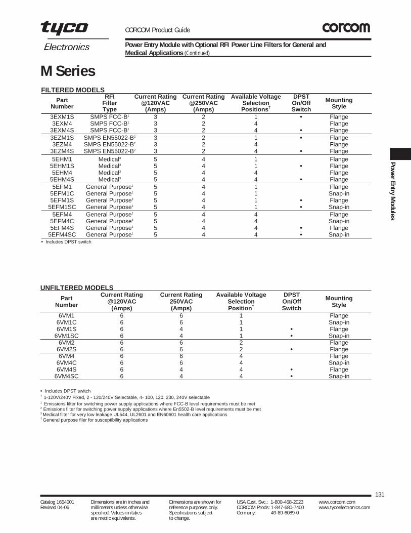
CORCOM Product Guide
131Catalog 1654001 Dimensions are in inches and Dimensions are shown for USA Cust. Svc.: 1-800-468-2023 www.corcom.com Revised 04-06 millimeters unless otherwise reference purposes only. CORCOM Prods: 1-847-680-7400 www.tycoelectronics.com
specified. Values in italics Specifications subject Germany: 49-89-6089-0 are metric equivalents. to change.
Power Entry M
odules
M Series
Power Entry Module with Optional RFI Power Line Filters for General andMedical Applications (Continued)
FILTERED MODELSPart RFI Current Rating Current Rating Available Voltage DPST Mounting
Number Filter @120VAC @250VAC Selection On/Off StyleType (Amps) (Amps) Positions† Switch3EXM1S SMPS FCC-B1 3 2 1 •• Flange3EXM4 SMPS FCC-B1 3 2 4 Flange
3EXM4S SMPS FCC-B1 3 2 4 •• Flange3EZM1S SMPS EN55022-B2 3 2 1 •• Flange3EZM4 SMPS EN55022-B2 3 2 4 Flange
3EZM4S SMPS EN55022-B2 3 2 4 •• Flange5EHM1 Medical3 5 4 1 Flange
5EHM1S Medical3 5 4 1 •• Flange5EHM4 Medical3 5 4 4 Flange
5EHM4S Medical3 5 4 4 •• Flange5EFM1 General Purpose‡ 5 4 1 Flange
5EFM1C General Purpose‡ 5 4 1 Snap-in5EFM1S General Purpose‡ 5 4 1 •• Flange
5EFM1SC General Purpose‡ 5 4 1 •• Snap-in5EFM4 General Purpose‡ 5 4 4 Flange
5EFM4C General Purpose‡ 5 4 4 Snap-in5EFM4S General Purpose‡ 5 4 4 •• Flange
5EFM4SC General Purpose‡ 5 4 4 •• Snap-in•• Includes DPST switch
UNFILTERED MODELS
Part Current Rating Current Rating Available Voltage DPST MountingNumber @120VAC 250VAC Selection On/Off Style(Amps) (Amps) Position† Switch
6VM1 6 6 1 Flange6VM1C 6 6 1 Snap-in6VM1S 6 4 1 •• Flange
6VM1SC 6 4 1 •• Snap-in6VM2 6 6 2 Flange
6VM2S 6 6 2 •• Flange6VM4 6 6 4 Flange
6VM4C 6 6 4 Snap-in6VM4S 6 4 4 •• Flange
6VM4SC 6 4 4 •• Snap-in
•• Includes DPST switch† 1-120V/240V Fixed, 2 - 120/240V Selectable, 4- 100, 120, 230, 240V selectable1 Emissions filter for switching power supply applications where FCC-B level requirements must be met2 Emissions filter for switching power supply applications where En5502-B level requirements must be met3 Medical filter for very low leakage UL544, UL2601 and EN60601 health care applications‡ General purpose filer for susceptibility applications

CORCOM Product Guide
132Catalog 1654001 Dimensions are in inches and Dimensions are shown for USA Cust. Svc.: 1-800-468-2023 www.corcom.com Revised 04-06 millimeters unless otherwise reference purposes only. CORCOM Prods: 1-847-680-7400 www.tycoelectronics.com
specified. Values in italics Specifications subject Germany: 49-89-6089-0 are metric equivalents. to change.
P Series
P Series
The CHAMELEON Adaptable Module for General, High Performance or Medical Applications
The P series power entry module offers fuller flexibility ofdesign in a more compact package.
As the first 10 amp module to provide all five power entryfunctions in one compact design, the CHAMELEONmodule readily adapts to its environment and the needs of international markets.
• Snap-in or flange mounting
• IEC power line connector
• Both North American and European fusing capabilities
• Two voltage selections
• Optional DPST on/off switch
• Filtering options for general purpose, medical and high-performance applications.
The CHAMELEON modules compact design and modularconstruction will allow you to select the power entry features you require — without altering the panel cutout.And the Chameleon module, with adapters, will fit any standard panel cutout.
The CHAMELEON module has four filter options. S models offer protection for general purpose applica-tions where line-to-ground and line-to-line noise must becontrolled. The filters are designed to meet low leakagerequirements of VDE portable equipment. They are available in current ratings of 3, 6 and 10 amps.
H models provide susceptibility protection without leak-age current associated with line-to-ground capacitors andare designed to allow equipment to meet UL 544 for patientcare and non-patient care equipment.
Also available is an interconnection block, B models. The block connects the voltage selection terminals of anunfiltered CHAMELEON module with a switch and an IECconnector to reduce external wiring.
L Models – High performance medical filter versions thatare designed to help bring most digital equipment (includ-ing switching power supplies) into compliance withEN55022, Level B (as well as FCC part 15J, Class B) conducted emissions limits while additionally allowingequipment to meet UL544, UL2601and EN60601 for patientcare equipment and non-patient care equipment. They are available with current ratings of 6 and 10 amps. High performance versions are available with horizontal mount-ing ears, single voltage, complete can shield with optionsfor switch, fuses and current ratings only. Extenders are not available.
Z Models – High performance filter versions are designedto help bring most digital equipment (including switchingpower supplies) into compliance with EN55022, Level B (as well as FCC Part 15J, Class B) conducted emissionslimits. They are available with current ratings of 6 and 10amps. High performance versions are available with horizontal mounting ears, no extenders, single voltage,complete can shield with options for switch, fuses and current ratings only.
PS000SS30PS Unfiltered PS Filtered
PE Filter with "A" Shield
UL RecognizedCSA CertifiedVDE Approved
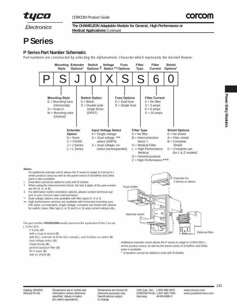
CORCOM Product Guide
133Catalog 1654001 Dimensions are in inches and Dimensions are shown for USA Cust. Svc.: 1-800-468-2023 www.corcom.com Revised 04-06 millimeters unless otherwise reference purposes only. CORCOM Prods: 1-847-680-7400 www.tycoelectronics.com
specified. Values in italics Specifications subject Germany: 49-89-6089-0 are metric equivalents. to change.
Power Entry M
odules
P Series Part Number SchematicPart numbers are constructed by selecting the alphanumeric character which represents the desired feature.
Additional extender which allows the P series to adapt to CORCOM's Lseries product cutout, as well as the panel cutout of Schaffner and Deltaparts is available. * Extenders cannot be added to units with B shields.
P Series
P S J 0 X S S 6 0Mounting StyleE = Mounting ears (Horizontal) S = Snap-inM = Mounting ears (Vertical)
ExtenderOption0 = NoneC = FN260J = J SeriesL = L Series
Switch Option0 = BlankS = Double pole single throw (DPST)
Input Voltage Select0 = Single voltageS = Dual voltage select (SMPS)X = Dual voltage select (series/parallel)
Fuse OptionsD = Dual fuseS = Single fuse
Filter Type0 = No filterB = Interconnection block H = Medical FilterL = High Performance MedicalS = General purposeZ = High Performance
Filter Current0 = No filter 3 = 3 amps6 = 6 ampsX = 10 amps
Shield Options0 = No shieldA = Filter shieldB = Complete ShieldC = Complete can (for L & Z models)
MountingStyle
ExtenderOptions*
SwitchOptions
VoltageSelect
FuseOptions
FilterType
FilterCurrent
ShieldOptions***‡
**
**
***
The part number PSJ0XSS60 would represent the equivalent of the CorcomJ Series 6J4:.
P Series (P)with a snap-in mount (S)with the J extender to fit the 6J4 cutout(J), and includes no switch (0)dual voltage select (X)single fusing (S), general purpose filter (S)for 6 amps (6)with no shield (0).
Extender forJ-Series or others
Optional filter
Optional switch
Fuse holder
The CHAMELEON Adaptable Module for General, High Performance or Medical Applications (Continued)
Notes:An additional extender which allows the P series to adapt to Corcom's L series product cutout as well as the panel cutout of Schaffner and Delta parts is also available.
• Extenders cannot be added to units with B shields † When using the interconnection block, the last 3 digits of the part number
are BX (0, A, or B) ‡ For alternative switch orientation options, please contact technical sup
port or your Corcom sales representative ** Dual voltage options only available with filter types O, H or S ••• High performance versions are available with horizontal mounting ears
(PE style), no extenders, single voltage, complete can shield with optionsfor switch, fuses, filter type (L or Z) and 6 or 10 amp current ratings only.

Input Voltage Selection Schemes
X - Dual Primary Transformer Type
S - Jumper Type
CORCOM Product Guide
134Catalog 1654001 Dimensions are in inches and Dimensions are shown for USA Cust. Svc.: 1-800-468-2023 www.corcom.com Revised 04-06 millimeters unless otherwise reference purposes only. CORCOM Prods: 1-847-680-7400 www.tycoelectronics.com
specified. Values in italics Specifications subject Germany: 49-89-6089-0 are metric equivalents. to change.
115V 230V
Note 1 Note 1
Note 1Note 1
A
B
C
D
Power on/off
Neutral
Provision forsingle fusing
G
H
Powerinput
Sel.Jumpers
SMPS
Hot
Ground
Note 1: Jumpers are required if a filter or interconnection module is not used.
Note 2: Location of optional filter. Jumpers are required if a filter or interconnection block is not used.
The P series of power entry modules provides a dual volt-age selector which is integrated with the fuseholder. Tosimplify the wiring in each individual application, TycoElectronics provides dedicated voltage selectors for differ-ent voltage selection schemes. The two most popularschemes are the parallel and serial for dual primary trans-formers and the “DPST switch” for switching mode powersupplies (jumper types.) P series products with an “S” asthe fifth digit are specifically designed for “jumper” typeapplications associated with switching mode power sup-plies. P series products with an “X” as the fifth digit arespecifically designed for dual primary transformer applica-tions. The voltage selector installed will allow proper wiringfrom these applications. No matter what voltage selectionscheme is used, wiring is always made to the same fourterminals.
P SeriesVoltage Selection
A Shield B Shield
The CHAMELEON Adaptable Module for General, High Performance or Medical Applications (Continued)
115V 230V
Note 1 Note 2
Note 2Note 1
A
B
C
D
Power on/off
115V
115VNeutral
Provision forsingle fusing
Transformerprimary
G
H
Hot
Ground
ShieldA new feature available on the P series is an RF shield. Themetal shield, available on filtered models, provides shield-ing from radiated emissions and provides an additional RFground for the filter to the case. The shield is available intwo versions, a shield of the filter components (designatedby A as the ninth digit) and a complete shield (designatedby B as the ninth digit). The A shield covers the filter por-tion of the module and increases performance of the filterby protecting the components from magnetic coupling.This shield improves RF ground connection to the casewhile still allowing the use of the P Series extender. The Bshield covers the entire power entry module with metal,protecting the equipment from all radiated noise. Usedwith the filter, the shield provides the most secure protec-tion from RFI noise problems. The B shield cannot be usedwith any extender.

CORCOM Product Guide
The CHAMELEON Adaptable Module for General, High Performance or Medical Applications (Continued)
135Catalog 1654001 Dimensions are in inches and Dimensions are shown for USA Cust. Svc.: 1-800-468-2023 www.corcom.com Revised 04-06 millimeters unless otherwise reference purposes only. CORCOM Prods: 1-847-680-7400 www.tycoelectronics.com
specified. Values in italics Specifications subject Germany: 49-89-6089-0 are metric equivalents. to change.
Power Entry M
odules
P SeriesFuseholder
Another feature of the P series power entry module is a ver-satile fusing arrangement. Its fuseholder can hold two 1/4”x 1-1/4” or 5 x 20mm fuses. It can also be converted toaccept one fuse with a conversion clip that bridges one ofthe two fuse chambers. The conversion clip is installed onthe P Series power entry modules set for single fusing(those with part numbers with an “S” as the sixth digit).Units with a “D” as the sixth digit do not include a conver-sion clip.
Interconnection Block
Also available is an interconnection block (B models). Theblock connects the voltage selection terminals of an unfil-tered CHAMELEON module with a switch and an IEC con-nector to reduce external wiring. Installation of the unfil-tered versions of the P series involves wiring of the IECsocket to the switch and the switch to the fuseholder. Laborcan be eliminated by ordering the product with an intercon-nection block. This feature, designated by a BX in the sev-enth and eighth digits, pre wires the module for easierinstallation. The wiring is protected with the plastic case tobetter prevent access to the terminals and connections.The dimensions of this alternative are the same as thefiltered versions.
Accessories
A full range of accessories are available for the P Series. To simplify customer installation wiring can be simplified byordering a PA100 connector assembly which is pre-wiredwith 6" of wire lead.
See page 143 for a complete list of all accessories available for this series.
Interconnection Block installed in place of filer.
Fuseholder shown with 5x20mm fuse
Conversion clip included for use in single fuse applications.
PA100 Assembly

CORCOM Product Guide
136Catalog 1654001 Dimensions are in inches and Dimensions are shown for USA Cust. Svc.: 1-800-468-2023 www.corcom.com Revised 04-06 millimeters unless otherwise reference purposes only. CORCOM Prods: 1-847-680-7400 www.tycoelectronics.com
specified. Values in italics Specifications subject Germany: 49-89-6089-0 are metric equivalents. to change.
P Series
The CHAMELEON Adaptable Module for General, High Performance or Medical Applications (Continued)
Specifications Maximum leakage current, each line-to-ground: †
H & L Models S & Z Models@ 120 VAC 60 Hz: 2 µA .25 mA@ 250 VAC 50 Hz: 5 µA .50 mA
†Applies to Filtered models only Hipot rating (one minute):
line-to-ground 1500 VACline-to-line 1450 VAC
Operating frequency: 50/60 HzRated voltage: 250 VACOperating voltages:
Selectable or Fixed 115/230 VACRated current: Unfiltered – 10A
Filtered – 3, 6 or 10ASwitch: Double-insulated, rated
for 10,000 operations at full load at51 Amp inrush current.
Fuseholder: Accepts one or two fuses1/4 x 1-1/4 or 5 x 20 mm
Conversion clip provided on fuseholderfor single fuse models.
Terminals:
Standard versions: .187 x 0.032[4.8 x .81] terminal tabs
High performance versions: .250 x 0.032[6.4 x .81] terminal tabs
Recommended use, mating connector - no solder
Minimum insertion loss in dB:
Line-to-ground in 50 ohm circuit
Current Frequency-MHzRating .03 .1 .15 .5 1 3 5 10 30
H Models03A 7 17 21 27 30 29 26 23 1506A - 8 11 15 17 19 18 16 1310A 3 5 8 10 12 11 11 10 10S Models03A 7 17 21 27 33 40 44 50 3206A - 8 12 17 23 32 36 44 3010A - 3 5 10 13 23 27 35 27
Current Frequency-MHzRating .01 .05 .1 .15 .5 1 5 10 30
Z Models06A 8 21 27 30 37 43 49 52 4210A 5 17 22 24 27 32 52 47 40L Models06A 8 21 27 29 34 35 25 21 1610A 5 17 22 23 24 25 21 18 14
Line-to-line in 50 ohm circuitCurrent Frequency-MHzRating .10 .15 .5 1 3 5 10 30
H Models03A 2 4 12 18 31 40 48 4106A 2 4 12 16 26 35 40 3510A 2 4 12 16 26 33 40 32S Models03A 2 4 12 15 30 48 50 4506A 2 4 12 15 22 42 55 4510A 2 4 12 15 22 42 55 45
Current Frequency-MHzRating .01 .05 .1 .15 .5 1 5 10 30
Z Models06A 10 15 34 44 75 75 75 70 6010A 10 20 20 35 67 75 75 70 60L Models06A 10 15 34 44 75 75 75 70 6010A 10 20 20 35 67 75 75 70 60
S Model
H Model
LINE LOAD
L Model
LINE LOAD
Z Model
Electrical Schematics

CORCOM Product Guide
137Catalog 1654001 Dimensions are in inches and Dimensions are shown for USA Cust. Svc.: 1-800-468-2023 www.corcom.com Revised 04-06 millimeters unless otherwise reference purposes only. CORCOM Prods: 1-847-680-7400 www.tycoelectronics.com
specified. Values in italics Specifications subject Germany: 49-89-6089-0 are metric equivalents. to change.
Power Entry M
odules
P Series
Catalog 1654001 Dimensions are in inches and Dimensions are shown for USA Cust. Svc.: 1-800-468-2023 www.corcom.com Revised 04-06 millimeters unless otherwise reference purposes only. CORCOM Prods: 1-847-680-7400 www.tycoelectronics.com
specified. Values in italics Specifications subject Germany: 49-89-6089-0 are metric equivalents. to change.
The CHAMELEON Adaptable Module for General, High Performance or Medical Applications (Continued)
Case Styles
PS/PSL
PE
B2
C
.2255.72A
.2255.72
B1
C
UnÞltered Filtered
D
E
.061.52
R Max
.020
.508R Min
(Note 1)
Panel CutoutNote1: For snap-in applications, the D sides of the cutout must have a .02 [.508] radius on the installation side.Snap-in models allow front mounting only. Not recommended for plastic panels.
B1
C
.2255.72
A
F
D Max. B2
C
.2255.72
Max.
UnÞltered Filtered
D
E
.061.52
R Max
.020
.508R Min
FPanel Cutout
PM
UnÞltered Filtered
D
FC
A
B1
.2255.72
Max. B2
.2255.72
Max.
E F
D
.061.52
R Max
Panel Cutout
Typical dimensions:Terminals: .187 x 0.032 [4.8 x .81] terminal tabs Holes: .055 [1.5] Dia. ± .004 [.10]Slot (Ground Terminal): .06 x .115 [1.52 x 2.92] ± .004 [.10] Mounting Holes (PE, PM only) : .135 [3.43] Dia. (2) countersunk

CORCOM Product Guide
138Catalog 1654001 Dimensions are in inches and Dimensions are shown for USA Cust. Svc.: 1-800-468-2023 www.corcom.com Revised 04-06 millimeters unless otherwise reference purposes only. CORCOM Prods: 1-847-680-7400 www.tycoelectronics.com
specified. Values in italics Specifications subject Germany: 49-89-6089-0 are metric equivalents. to change.
P Series
PE High Performance
UnÞltered FilteredA B1
C
.2255.72Max.
B2.2255.72
D
E
.061.52
R Max
.020
.508R Min
(Note 1)
Panel Cutout
A
C
3.93 Max.
B2
2.17 Max.
F .2255.72
DRear View
2.39 Max.
Note 1: For snap-in applications, the D sides of the cutout must have a .02 [.508] radius on the installation side. Snap-in models, allow front mounting only.
Note 1: Use cutout for PE Style.
Case Styles (continued)
The CHAMELEON Adaptable Module for General, High Performance or Medical Applications (Continued)
Typical dimensions:Terminals: .187 x 0.032 [4.8 x .81] terminal tabs Holes: .055 [1.5] Dia. ± .004 [.10]Slot (Ground Terminal): .06 x .115 [1.52 x 2.92] ± .004 [.10] Mounting Holes (PE, PM only) : .135 [3.43] Dia. (2) countersunk
Typical dimensions:Terminals: .250 x 0.032 [6.4 x .81] terminal tabs Holes: .07 [1.8] Dia. (2)Slot (Ground Terminal): .07 x .16 [1.8 x 4.1] Mounting Holes: .135 [3.43] Dia. (2) countersunk
PSC/PSJ

CORCOM Product Guide
139Catalog 1654001 Dimensions are in inches and Dimensions are shown for USA Cust. Svc.: 1-800-468-2023 www.corcom.com Revised 04-06 millimeters unless otherwise reference purposes only. CORCOM Prods: 1-847-680-7400 www.tycoelectronics.com
specified. Values in italics Specifications subject Germany: 49-89-6089-0 are metric equivalents. to change.
Power Entry M
odules
P Series
Rear View
Case Dimensions
Part No. A B1 B2 C D E F
(max) (max) (max) (max)
PS 1.24 1.93 2.13 2.31 1.06∆∆ 2.201* —31.49 49.02 54.1 58.67 26.93 55.91
PSL 1.24 1.93 2.13 2.31 1.12 2.201* —31.49 49.02 54.1 58.67 28.45 55.91
PE 1.98 1.93 2.13 2.31 1.122 2.201* 1.575
50.29 49.02 54.1 58.67 28.5 55.91 40.0
PM 1.24 1.93 2.13 2.9 1.06 2.13 2.496
31.49 49.02 54.1 73.66 26.93 54.1 63.4
PSC 1.24 1.93 2.13 2.51 1.06 2.52 —31.49 49.02 54.1 63.75 26.93 64.01
PSJ 1.24 1.93 2.13 2.72 1.06 2.6+—
31.49 49.02 54.1 69.09 26.93 66.0
PE 1.98 — 4.42 2.31 1.12 2.201 1.575High 50.29 112.27 58.67 28.5 55.91 40.0Performance
* Panel cutout for thickness of .031 - .079 [0.8 - 2.0]. For panel thickness at .083 - .114 [2.1 - 2.9] use 2.213 [56.21].
+ Panel cutout for thickness of 0.06 - 0.09 [0.76 - 2.29].∆∆ For shielded models use D=1.12 +.008/-.000.Shields can be used only with filtered models. Shields add approximately 0.06" to depth.B shield may not be used with J or C extender.
+.008/-.000+.20/-.00
+.008/-.000+.20/-.00
The CHAMELEON Adaptable Module for General, High Performance or Medical Applications (Continued)
Shielding
2.19 Max0.225.508Max.
0.225.508Max.
2.19 Max
A Shield B Shield
A B C D A B C D
GND GND
L N
Filtered UnÞltered

CORCOM Product Guide
AC Connectors
140Catalog 1654001 Dimensions are in inches and Dimensions are shown for USA Cust. Svc.: 1-800-468-2023 www.corcom.com Revised 04-06 millimeters unless otherwise reference purposes only. CORCOM Prods: 1-847-680-7400 www.tycoelectronics.com
specified. Values in italics Specifications subject Germany: 49-89-6089-0 are metric equivalents. to change.
SR Series
SR SeriesThe SR series includes a full line of popular AC recepta-cles. These male and female power line connectorsinclude snap-in and flange mounted models.
SpecificationsOperating voltages: 120/250 VACMaterials:
Insulator Thermoplastic (UL V-2 flame class)Prongs Solid brass, nickel platedTerminals Brass, tin plated
Temperature Rating: For "cold" connections, 65˚C
AC Connectors
UL RecognizedCSA CertifiedVDE Approved
6ESRMC2
6ESRM-3
6ESRM-P
Current Current Input Output Terminals MountingPart Number Rating Rating Configuration Terminal Panel
@UL/CSA @VDE Style Dimensions Style Thickness(in./mm) (in./mm)s
6ESRM-P 15 10 Male PC Terminals Fit .063/1.6 Hole Flange –
6ESRM-3 15 10 Male Quick Disconnect . 25 x .032/ Flange _6.3 x 0.8
6ESRMC2 15 10 Male Quick Disconnect .187 x .032/ Snap-in .059/1.54.8 x 0.8
6ESRFC3 15* 10 Female Quick Disconnect .25 x .032/ Snap-in .059/1.56.3 x 0.8
6ESRF-3 15* 10 Female Quick Disconnect .25 x .032/ Flange _6.3 x 0.8
* UL recognized and CSA certified for 15 amps at 125V. VDE approved for 10 amps at 250V.s Panel thickness tolerance is ±.004 [±.10]
6ESRFC36ESRF-3

CORCOM Product Guide
AC Connectors (Continued)
141Catalog 1654001 Dimensions are in inches and Dimensions are shown for USA Cust. Svc.: 1-800-468-2023 www.corcom.com Revised 04-06 millimeters unless otherwise reference purposes only. CORCOM Prods: 1-847-680-7400 www.tycoelectronics.com
specified. Values in italics Specifications subject Germany: 49-89-6089-0 are metric equivalents. to change.
Power Entry M
odules
SR SeriesCase Styles
Case Dimensions
Part No. A B C D E F(max) ±.017- .006 (max) (max) (max) (max)
±.43 -.15
6ESRM-P 1.969 1.575 1.11 0.88 1.051 1.19250.0 40.0 28.2 22.4 26.7 30.28
6ESRM-3 1.977 1.575 0.896 1.187 1.224 —50.2 40.0 22.8 30.1 31.09
6ESRMC2 1.197 — 0.892 1.078 1.205 —30.4 22.7 27.4 30.6
6ESRFC3 1.39 — 1.11 1.258 1.406 —35.3 28.2 31.95 35.7
6ESRF-3 1.969 1.575 1.154 1.258 1.406 —50.0 40.0 29.3 31.95 35.6
6ESRM-P (Flange)
6ESRFC3 (Snap-in)
6ESRF (Flange)
6ESRM-3 (Flange)
6ESRMC2 (Snap-in)
ECD
A B F
1.193*30.3
.886*22.5
.1423.6 Dia. (2)
+.008, -.00+.200, -.00
*
.2325.9
R Max.
Rear Mount
.62615.9
B
.1343.4
Dia. (2)
.3589.1
.063 1.6
Dia. (3)
.1423.6 Dia. (2)
.3829.7
.78720
1.57540.0
.1423.6
.1263.2
.1343.4
Dia. (2)
EC
DA B
.1423.6
Dia. (2)
.2325.9
R
1.189*30.2
.894*22.7
.1423.6
Dia. (2)
.1975.0
R
1.079*27.4
.780*19.6 +.008, -.00
+.200, -.00*
Rear Mount Front Mount
.1343.4
Dia. (2)
1.059 .01626.9 .40
MountingCutout
MountingCutout
EC
DA
.1975.0
R
1.079*27.4
.780*19.6
+.008, -.00+.200, -.00
*Front Mount
.1223.1
MountingCutout
EC
DA
.1574.0
R
1.272*32.2
.976*24.8
+.008, -.00+.200, -.00
*
Front Mount
.1102.8
MountingCutout
EE
D
.1102.8C
A B
.1423.6
Dia. (2)
.2566.5
R
1.272*32.3
.976*24.8 +.008, -.00
+.200, -.00*
Front Mount
.1423.6
Dia. (2)
MountingCutout

Fuseholder — Part No. LA200 Accommodates one 1/4" x 1-1/4" North American fuse for L series only.
Fuseholder — Part No. LA201 Accommodates one 5 x 20mm metric fuse for L seriesonly.
Voltage Wheel — Part No. LA302Two-voltage selection drum for use with HL4 and DL4models. Marked 115V/230V.
Voltage Wheel — Part No. LA303Three-voltage selection drum or use with HL4 and DL4models. Marked 110V/220V/240V.
Voltage Wheel — Part No. LA304Four-voltage selection drum for use with HL4 and DL4models. Marked 100V/120V/220V/240V. One LA304comes standard with each HL4 and DL4 model.
Blank — Part No. LA400Blank to replace switch in single voltage selection models.DL1 and HL1 models.
Insulating Boot — Part No. LA601Plastic shroud to cover back of EDL and EHL power entrymodules preventing inadvertent access.
CORCOM Product Guide
Accessories
142Catalog 1654001 Dimensions are in inches and Dimensions are shown for USA Cust. Svc.: 1-800-468-2023 www.corcom.com Revised 04-06 millimeters unless otherwise reference purposes only. CORCOM Prods: 1-847-680-7400 www.tycoelectronics.com
specified. Values in italics Specifications subject Germany: 49-89-6089-0 are metric equivalents. to change.
General
Insulating Boot — Part No. FA601Plastic shroud to cover back of IEC connector style filterswith style 1 terminals for EC, ED, EEA, EEB, EEJ, EF Series.
J Series - Voltage Selecting and FusedConnector
L Series - Power Entry Modules
Tool — Part No. JA500Extractor tool for removal and insertion of voltage selectorcard in J series.
Voltage Card — Part No. JA302Two-voltage selection card for use with J series. Marked115V/230V.
Voltage Card — Part No. JA304Four-voltage selection card for use with J series. Marked110V/120V/220V/240V. One JA304 comes standard witheach J series module.
Line Cord — Part No. GA4007 1/2 foot, 3-conductor line cord to mate with models with-in the catalog. 1250 watt, 10A - 125 VAC SVT, Black, UL,CSA.
Not recommended for patient care applications due toleakage current of the line cord.
JA500
JA302

Assembly — Part No. MA100Power interconnect assembly for voltage select models ofthe M series. Simplifies connection of power entry moduleto power supply. Designed for use with either filtered orunfiltered voltage selection models. 8.5" wire leads.
Part No. MA101 - Plug OnlyPart No. MA102 - Pins on StripsPart No. MA103 - Pins on Reel (7,000 pins)Part No. MA104 - Pins Only
Assembly — Part No. MA400 Medical safety bracket kit for use with HM models. Bracketallows customer to undergo UL544 abnormal conditiontesting without removal of fuse(s) in power entry module.
Part No. MA401 - Bracket OnlyPart No. MA402 - Standoff Only
Voltage Card — Part No. MA302Two-voltage selection capability for use with M seriespower entry modules. Marked 120V/240V. One MA302comes standard with two-voltage M series modules.
Voltage Card — Part No. MA304Four-voltage selection capability for use with M seriespower entry modules. Marked 100V/120V/230V/240V. One MA304 comes standard with four-voltage M seriesmodules.
CORCOM Product Guide
Accessories (Continued)
143Catalog 1654001 Dimensions are in inches and Dimensions are shown for USA Cust. Svc.: 1-800-468-2023 www.corcom.com Revised 04-06 millimeters unless otherwise reference purposes only. CORCOM Prods: 1-847-680-7400 www.tycoelectronics.com
specified. Values in italics Specifications subject Germany: 49-89-6089-0 are metric equivalents. to change.
Power Entry M
odules
M Series - Power Entry Modules
P Series
Insulating Boot — Part No. MA601Plastic shroud to cover back of VM and EFM power entrymodules preventing inadvertent access to tracings.
Part No. MA601 - fits M4S versionsPart No. MA602 - fits M1S versionsPart No. MA603 - fits M4 versionsPart No. MA604 - fits M1 versions
Assembly — Part No. PA100Power connector assembly for voltage select modules ofthe P series. Simplifies the connection of power entry mod-ule to power supply. Designed for use with either filtered orunfiltered modules. Includes 6 inch wires (4).Part No. PA101 - Plug OnlyPart No. PA102 - Pins OnlyPart No. PA105 - Same as PA100, except has 2 wires for
no voltage selection models
J Extender — Part No. PA400Extends P series module to fit J panel cutout. Cannot beused with B shield.L Extender — Part No. PA410Extends P series width to fit L panel cutout (use two permodule). Unshielded versions only. C Extender — Part No. PA420Extends P series height by .20"
PA101
0
0
0
00
42
22
1

CORCOM Product Guide
144
Engineering Notes
Catalog 1654001 Dimensions are in inches and Dimensions are shown for USA Cust. Svc.: 1-800-468-2023 www.corcom.com Revised 04-06 millimeters unless otherwise reference purposes only. CORCOM Prods: 1-847-680-7400 www.tycoelectronics.com
specified. Values in italics Specifications subject Germany: 49-89-6089-0 are metric equivalents. to change.
CORCOM Product Guide
DC Filters — Table of Contents
Introduction . . . . . . . . . . . . . . . . . . . . . . . . . . . . . . . . . . . . . . . . . . . . . . . . . . . . . . . . . . . .146Selector Chart . . . . . . . . . . . . . . . . . . . . . . . . . . . . . . . . . . . . . . . . . . . . . . . . . . . . . . . . . .147DA Series . . . . . . . . . . . . . . . . . . . . . . . . . . . . . . . . . . . . . . . . . . . . . . . . . . . . . . . . .148, 149DC Series . . . . . . . . . . . . . . . . . . . . . . . . . . . . . . . . . . . . . . . . . . . . . . . . .150, 151, 152, 153P Series . . . . . . . . . . . . . . . . . . . . . . . . . . . . . . . . . . . . . . . . . . . . . . . . . . . . . . . . . . .154, 155
145Catalog 1654001 Dimensions are in inches and Dimensions are shown for USA Cust. Svc.: 1-800-468-2023 www.corcom.com Revised 04-06 millimeters unless otherwise reference purposes only. CORCOM Prods: 1-847-680-7400 www.tycoelectronics.com
specified. Values in italics Specifications subject Germany: 49-89-6089-0 are metric equivalents. to change.
DC
Filters

CORCOM Product Guide
Introduction
S TAY C O N N E C T E D W I T H C O R C O M PRODUCTS
Tyco Electronics is a world leader in EMI-RFI filteringtechnology. Since 1955, Tyco Electronics has beenproviding EMI-RFI solutions to leading computer,industrial and telecommunications companiesworldwide. Whether you are meeting FCC andinternational EMC standards on EMI-RFI emissions or developing a newly designed piece of equipmentfrom being disturbed by EMI-RFI in the environment,a power line filter will help your equipment withcompliance.
This section highlights Tyco Electronics product offering ofDC rated products. Whether the issues involve filteringnoise on the Data Lines or on the Power Lines, TycoElectronics can provide the needed solutions for bothsusceptibility and to help achieve system emissionsand immunity compliance.
As new technologies in the Telecom-Datacom industry aredeveloped and introduced, Tyco Electronics continuesto design and develop new products to address theEMI-RFI filtering issues. Tyco Electronics designengineers are very actively working with telecom-datacom system engineers to solve EMI-RFI issues.
In working with two of the leading North Americancommunications equipment companies, Tyco Electronicsengineers solved the EMI-RFI issues present byapplying 48 VDC filters at the primary input of the DC power supply. One of the applications was onnetwork routing equipment and required a CORCOMtwo-stage 48VDC filter on the input to the DC powersupply. CORCOM products applied high-frequencyattenuating 48VDC filters on the load side of the DC power supplies to solve high-frequency EMI-RFIissues.
Tyco Electronics has provided solutions in both power linefiltering and signal line filtering applications for manyleading communications companies. As datatransmission speeds increase and EMI-RFI issuesmultiply, Tyco Electronics has developed products tobetter solve the newer challenges communicationscompanies encounter.
CORCOM DC power line and signal line filters have beenincluded in:
• Network routing equipment
• Servers
• Modems
• Switching equipment
• Wireless cabinets
• Ethernet hubs
• Base stations
• Repeater stations
• Power supplies for all types of
communications equipment.
Tyco Electronics has developed filter products specificallyfor the communications industry including:
• DC power line clean-up filters
• Medium and multiple-stage high-performanceDC power line filters
• High frequency DC power line filters
(up to 3GHz)
• AC voltage power line clean-up filters
• Medium and high performance AC filters
• Data-transmission signal line filters.
CORCOM DC Filters are available in versions that cansolve a wide variety of EMI-RFI issues. Tyco Electronicshas solved basic EMI-RFI issues with simple clean-up DC filters and has solved more complex EMI-RFIissues with mid-range and multiple-stage highperforming DC filters. Tyco Electronics also hassolved high-frequency noise problems (up to 3GHz)encountered with high-speed data transmission and switching power supplies.
146Catalog 1654001 Dimensions are in inches and Dimensions are shown for USA Cust. Svc.: 1-800-468-2023 www.corcom.com Revised 04-06 millimeters unless otherwise reference purposes only. CORCOM Prods: 1-847-680-7400 www.tycoelectronics.com
specified. Values in italics Specifications subject Germany: 49-89-6089-0 are metric equivalents. to change.

CORCOM Product Guide
DC Rated Filters
147Catalog 1654001 Dimensions are in inches and Dimensions are shown for USA Cust. Svc.: 1-800-468-2023 www.corcom.com Revised 04-06 millimeters unless otherwise reference purposes only. CORCOM Prods: 1-847-680-7400 www.tycoelectronics.com
specified. Values in italics Specifications subject Germany: 49-89-6089-0 are metric equivalents. to change.
DC
Filters
DA/DAS
P
DC
Series
3-pin Inlet
2-pin Inlet
1/4” TerminalPCB
1/4” Terminal
• Snap-in Panel
• Flange Panel
• Snap-in Panel
• Flange Panel
Fuse
• Circuit Breaker• High frequency
Performance
3, 6, 10, 15
3, 6, 10
15, 30, 60, 100, 125
• Bulkhead
• Flange Chassis
• Redundant Stud
• Terminal Block
• Redundant Stud
• Terminal Block
Input Output Mounting Options Current Rating

CORCOM Product Guide
Compact RFI Line Filter with DC Inlet Connector
The DA Series filters were designed as general purposeline filters for DC applications up to 125VDC. They arecompact with a 3-pin inlet connector. They are available in3, 6, 10 and 15 amp versions. They are flange mount with1/4” or PCB terminals.
The DA Series addresses the increasing need for DC ratedfilters with a standard DC power inlet. It was designed andfirst used for communication oriented customer premisesequipment and central office equipment, but is notrestricted to that. Any internal DC connection within largermulti-component systems, or external DC connectionbetween user installed components which require filteringwill benefit. Some examples include desktop servers,routers, switches, multiplexors, aggregators, concentrators,process control equipment as well as DC poweredperipheral equipment.
The DA Series mates with a standard MOLEX connector(HCS Series) which is readily available and better preventsaccidental connection to AC power.
SpecificationsHipot rating (one minute):
line-to-ground 2250 VDC
line-to-line 1450 VDCRated voltage (max): 125 VDCOperating ambient temperature range
@ rated current Ir : -10˚C to +55˚C
In an ambient, Ta, higher than +55˚C, the maximumoperating current, Io, is as follows:
Minimum insertion loss in dB:
Line-to-ground in 50 ohm circuit
Current Frequency-MHzRating .05 .1 .15 .5 1 3 5 10 30 100 200
0 3A 6 9 11 26 41 48 52 55 46 22 160 6A 2 4 6 18 30 37 42 48 42 - -10A - 1 4 8 17 25 30 36 38 21 1115A - - - 3 5 13 19 25 29 10 14
Line-to-line in 50 ohm circuit
Current Frequency-MHzRating .05 .1 .15 .5 1 3 5 10 30 100 200
0 3A - 4 7 16 18 37 47 50 43 31 360 6A - 4 7 19 21 27 40 53 41 - -10A 2 4 6 17 22 23 32 48 38 30 2615A - - 2 17 19 29 33 37 37 31 28
*For higher amperage versions, contact Tyco Electronics.
148Catalog 1654001 Dimensions are in inches and Dimensions are shown for USA Cust. Svc.: 1-800-468-2023 www.corcom.com Revised 04-06 millimeters unless otherwise reference purposes only. CORCOM Prods: 1-847-680-7400 www.tycoelectronics.com
specified. Values in italics Specifications subject Germany: 49-89-6089-0 are metric equivalents. to change.
DA Series
DA Series
Electrical Schematic
LINE LOAD
90 - Ta35
Io = Ir
EN60 950
UL RecognizedCSA CertifiedTUV Approved
DAF1
DAS1DAFP

CORCOM Product Guide
Compact RFI Line Filter with DC Inlet Connector (Continued)
Case StylesDAF1
149Catalog 1654001 Dimensions are in inches and Dimensions are shown for USA Cust. Svc.: 1-800-468-2023 www.corcom.com Revised 04-06 millimeters unless otherwise reference purposes only. CORCOM Prods: 1-847-680-7400 www.tycoelectronics.com
specified. Values in italics Specifications subject Germany: 49-89-6089-0 are metric equivalents. to change.
DC
Filters
DA Series
E
D
C
A BGround
D
E
0.23 max.A
C
B
Rear View
Typical dimensions:Terminals: .250 [6.35] (3) Holes: .07 [1.8] Dia.(2) Slot: .07 x .16 [1.8 x 3.8] (1)
Typical dimensions:Terminals: .250 [6.35] (3) Holes: .07 [1.8] Dia.(2) Slot: .07 x .16 [1.8 x 3.8] (1)
Typical dimensions:Mounting holes: .132 [3.35] Dia. (2) with .260 [6.60] Dia. x 90˚C countersunk for #4 flathead screw.
DAFP
PCB Layout (board viewed from component side)
EB
C
AD
.551
.380 Max.
.537 Ref.
Ground
0.55113.99
0.52013.21
0.1042.64
Center pin to panel .685±.01517.40±.38
Ground
(3 holes)
Recommended Panel Cutout
.1403.56
.123.05
.82020.8
R
Dia. (2)
1.57540.01
.1403.56
.2345.94
.90022.9
R
Dia. (2)1.20030.48
1.57540.01
1.20030.48
Back Mount Front Mount
Mating Connectors
CORCOM Part Number:
GA310 - Custom connector assembly with 3, 36” long 18
gauge wires to mate with DA Series filter
MOLEX Component Part Numbers:
03-12-1036 Connector housing to mate with DA Series
18-12-1222 Female Terminal (3 needed per housing)
Red
Green/Yellow
Black
DAS1
DAF
"A"
0.81520.70
0.1884.78(4x)
R
DAS
Typical dimensions:Mounting Holes: .188 [4.78] Dia. (2) Torque: 18 ± 2 in. lb.
Panel Thickness A Dim.±.0020.031 - 0.052 [.79 - 1.32] 1.260 [32.00]0.046 - 0.068 [1.17 - 1.73] 1.350 [34.29]
Case DimensionsA B C D E
Part No. (max) (max) (max) ±.010 (max)± .25
DAF1 2.15 1.12 0.81 1.575 1.9854.61 28.45 20.57 40.01 50.29
DAS1 1.98 1.10 0.81 0.96* 1.4150.29 27.94 20.57 24.38 35.81
DAFP 1.54 1.12 0.81 1.575 1.9839.12 28.45 20.57 40.01 50.29
*represents Max. dimension
Part Numbers3DAF1 10DAF13DAS1 10DAS13DAFP 10DAFP6DAF1 15DAF16DAS1 15DAS16DAFP 15DAFP
DC Connector No. GA310

CORCOM Product Guide
RFI Power Line Filters for DC Applications
150Catalog 1654001 Dimensions are in inches and Dimensions are shown for USA Cust. Svc.: 1-800-468-2023 www.corcom.com Revised 04-06 millimeters unless otherwise reference purposes only. CORCOM Prods: 1-847-680-7400 www.tycoelectronics.com
specified. Values in italics Specifications subject Germany: 49-89-6089-0 are metric equivalents. to change.
DC Series
DC SeriesThe DC series filters were designed as general purpose line filtersfor DC applications. They are available with or without circuitbreakers for extra protection. They are available with feed-throughcapacitors for added high frequency performance. The DC seriesis designed to comply with UL 1283, CSA 22.2 No. 8 andEN60950.The DC series was developed in response to the increasingdemand for DC filtering in the telecom-datacom market. Thesefilters are generally used in central office equipment like switches,routers, and hubs to clean up the 48 VDC power, but are notexclusive to that equipment. They can also be used at the primaryinput of the DC power supply. The DC Series is available in both aflange mount (DCF) and bulkhead mount (DCB) configuration. Circuit Breaker Features (B Suffix)
• always hold 100% of rated current independent of ambienttemperature (minimize nuisance tripping)
• Always trip at 125% of rated current independent of ambienttemperature
• Can be combined with feed through capacitor in bulk headmount (DCB prefix) for high performance applications (BFSuffix)
Feed Through Capacitor for High Performance (F Suffix)• High performance results out to 3Ghz• Available only in bulk head (DCB prefix ) configuration only• Can be combined with circuit breaker feature (BF Suffix)
Hipot rating (one minute):
line-to-ground 2250 VDCline-to-line 1450 VDC
Operating Voltage (max): 80 VDC
Operating Ambient Temperature Range:(@ rated current Ir) -10˚C to +55˚C
In an ambient, Ta, higher than +55˚C, the maximum operating current, Io, is as follows:
Specifications
Electrical SchematicsStandard Performance Version
High Frequency Performance Version
Note 1
Note 2Note 3
Note 4
Note 1
LINE LOAD
Note 3
Note 2
Note 4
Note 1
LINE LOAD
Minimum insertion loss in dB:Standard PerformanceLine-to-ground in 50 ohm circuitCurrent Frequency-MHzRating .01 .05 .1 .15 .5 1 3 5 10 3015A - 1 12 20 41 45 61 63 47 3930A - 4 15 23 47 59 64 56 44 3660A - - 9 17 38 40 59 50 39 34
100A - - 10 18 38 39 53 50 35 21125A - - 12 18 30 32 44 49 29 18Line-to-line in 50 ohm circuitCurrent Frequency-MHzRating .01 .05 .1 .15 .5 1 3 5 10 3015A 7 22 27 30 30 36 56 49 38 3130A 7 22 28 31 32 59 56 51 41 2860A 15 30 36 40 40 35 60 51 39 32
100A 14 29 35 39 33 30 53 53 41 30125A 14 24 35 39 40 28 53 60 42 33
High Frequency Performance ("F" & "BF" Styles)Line-to-ground in 50 ohm circuit
Current Frequency-MHz50 300to to
Rating .01 .05 .1 .15 .5 1 3 5 10 20 300 300015A - 1 12 20 41 45 55 50 45 25 50 3030A - 4 15 20 46 58 60 60 48 35 50 3060A - - 9 16 38 42 52 60 48 26 40 30
100A - - 9 16 38 42 52 60 42 26 40 30125A - - 9 16 28 34 46 54 34 34 40 30Line-to-line in 50 ohm circuitCurrent Frequency-MHzRating .01 .05 .1 .15 .5 1 3 5 10 2015A 7 22 27 30 30 50 60 60 60 3630A 7 22 27 30 33 56 60 60 60 4060A 15 30 36 40 37 26 46 54 48 30
100A 14 29 35 39 33 30 56 53 41 30125A 14 29 35 39 40 28 53 60 42 33
UL RecognizedCSA CertifiedTUV Approved
EN60 950
Resistor location for reference only.Note 1: Depicts redundant style 6 terminals.Note 2: Depicts optional circuit breaker. Note 3: For 100 & 125A versions delete second coil.Note 4: Depicts style 10 terminal versions which have separate ground stud.
85 - Ta30
Io = Ir
DC

Cutout Dimensions Recommended Panel Cutouts
A
B
CHoles: .157 [3.99] Dia. (4)See case dimensions forspacing.
Tolerance: ±.005/±.13
DCB6/DCB6FDCB10/DCB10F(Viewed from filter side)
FB
A E
C
D
Holes: .157 [3.99] Dia. (4)See case dimensions forspacing.
Tolerance: ±.005/±.13
DCB6B & DCB10B – 15 to 60 Amps(Viewed from filter side)
B
A
C
1.25031.75 .625
15.88
.2626.65
1.55739.55
1.500 x 0.78138.10 x 19.84
Holes: .157 [3.99] Dia. (4)See case dimensions forspacing.
Tolerance: ±.005/±.13
DCB6B & DCB10B – 100 to 125 Amps(Viewed from filter side)
Part Numbers
15DCB10F30DCB10F60DCB10F
100DCB10F125DCB10F15DCB6BF30DCB6BF60DCB6BF
100DCB6BF125DCB6BF15DCB10BF30DCB10BF60DCB10BF
100DCB10BF125DCB10BF
15DCB6F30DCB6F60DCB6F
100DCB6F125DCB6F
15DCF630DCF660DCF6
100DCF6125DCF615DCF6B30DCF6B60DCF6B
100DCF6B125DCF6B
15DCB630DCB660DCB6
100DCB6125DCB615DCB6B30DCB6B60DCB6B
100DCB6B125DCB6B
15DCF1030DCF1060DCF10
100DCF10125DCF1015DCF10B30DCF10B60DCF10B
100DCF10B125DCF10B
15DCB1030DCB1060DCB10
100DCB10125DCB1015DCB10B30DCB10B60DCB10B
100DCB10B125DCB10B
Standard Performance High Performance
CORCOM Product Guide
RFI Power Line Filters for DC Applications (Continued)
151Catalog 1654001 Dimensions are in inches and Dimensions are shown for USA Cust. Svc.: 1-800-468-2023 www.corcom.com Revised 04-06 millimeters unless otherwise reference purposes only. CORCOM Prods: 1-847-680-7400 www.tycoelectronics.com
specified. Values in italics Specifications subject Germany: 49-89-6089-0 are metric equivalents. to change.
DC
Filters
DC Series
DCB6 / DCB6F & DCB10 / DCB10F
Part No. A B C15DCB6(F) 1.375 1.249 3.47230DCB6(F) 34.93 31.72 88.1915DCB10(F) 1.250 1.000 3.47230DCB10(F) 31.75 25.40 88.19
60DCB6(F) 1.375 1.249 3.47234.93 31.72 88.19
60DCB10(F) 1.674 1.010 3.44342.52 25.65 87.45
100DCB6(F) 1.700 1.549 3.472125DCB6(F) 43.18 39.34 88.19
100DCB10(F) 1.954 1.500 2.83049.63 38.10 71.20
125DCB10(F) 2.250 1.590 2.72557.15 40.39 69.22
DCB6 / DCB6F & DCB10 / DCB10F
Part No. A B C100DCB6B(F)100DCF6B 1.700 1.549 4.222125DCB6B(F) 43.18 39.34 107.23125DCF6B100DCB10B(F) 1.954 1.50 4.295100DCF10B 49.63 38.10 109.09
125DCB10B(F) 2.250 1.590 4.14757.15 40.39 105.33
125DCF10B 2.250 1.590 2.72557.15 40.39 105.33
** All cutout dimensions ± .005 [±.13]
DCB6B & DCB10B (15 to 60 Amps)
Part No. A B C D E F15DCB6B(F) 1.50 0.781 1.308 3.472 1.375 1.24915DCF6B 38.10 19.84 33.22 88.19 34.93 31.7215DCB10B(F) 1.50 0.781 1.308 3.472 1.250 1.00015DCF10B 38.10 19.84 33.22 88.19 31.75 25.4030DCB6B(F) 1.50 0.781 1.308 3.472 1.375 1.24930DCF6B 38.10 19.84 33.22 88.19 34.93 31.7230DCB10B(F) 1.50 0.781 1.308 3.472 1.250 1.030DCF10B 38.10 19.84 33.22 88.19 31.75 25.4060DCB10B(F) 1.50 0.781 1.308 3.443 1.674 1.01060DCF10B 38.10 19.84 33.22 87.45 42.52 25.65 60DCF6B(F) 1.50 0.781 1.308 3.472 1.375 1.24960DCF6B 38.10 19.84 33.22 88.19 34.93 31.72

CORCOM Product Guide
RFI Power Line Filters for DC Applications (Continued)
Case Styles
DCF10 (15 & 30 Amp)
F
D
AC
B
E
LINE
LOAD
-VDC
RTN
OF
FO
FF
ON
ON
-VDC
RTN
Tapped insert: 6-32 (4)
A
D
E
F
C
BLINE
LOAD
RTN
-VDC
RTN
-VDC
Note: Delete circuit breaker for DCB10 models.
Typical dimensions:Mounting Holes: .156 x .203 [4.0 x 5.2] Dia. (4)
DCF10B (15 & 30 Amp)
B
AC
D
E
F
-VDC
RTN
-VDC
RTN
LINE
LOADO
FF
OF
FO
NO
N
Tapped insert: 6-32 (4)
Typical dimensions:Mounting Slots: .260 x .39 [6.6 x 9.9] (4)
DCB6 & DCB6B
F
DB
AE
C
LINE
LOAD
-VDC
RTN
VDCVDC
RTNRTN-VDC
RTNOF
FO
FF
ON
ON
Tapped insert: 6-32 (4)
Note: Delete circuit breaker for DCB6 models.
DCF6B
DCB10B (15 & 30 Amp)
B
AC
D
E
F
LINE
LOAD
-VDC
RTN
-VDC
RTNOF
FO
FF
ON
ON
Tapped insert: 6-32 (4)
Typical dimensions:Mounting Slots: .260 x .39 [6.6 x 9.9] (4)
DCF6A
D
E
F
C
BLINE
LOAD
-VD
C
RT
N
-VD
C
RT
N
Typical dimensions:Mounting Slots: .260 x .39 [6.6 x 9.9] (4)Mounting Holes: .203x.156 [5.2 x 4.0] (4)
Note: 15A & 30A versions come with mounting holes in place of mounting slots.
DCB10 & DCB10B (60 to 125 Amp)
F
D
AC
B
E
LINE
LOAD
RT
N
VD
C
RT
N
VD
C
OF
FO
FF
ON
ON
Tapped insert: 6-32 (4)
Note: Delete circuit breaker for DCB10 models
152Catalog 1654001 Dimensions are in inches and Dimensions are shown for USA Cust. Svc.: 1-800-468-2023 www.corcom.com Revised 04-06 millimeters unless otherwise reference purposes only. CORCOM Prods: 1-847-680-7400 www.tycoelectronics.com
specified. Values in italics Specifications subject Germany: 49-89-6089-0 are metric equivalents. to change.
DC Series
DCF10 (60 to 126 Amps)A
D
E
F
C
BLINE
LOAD
RTN
-VDC
RTN
-VDC
Typical dimensions:Mounting Slots: .260 x .39 [6.6 x 9.9] (4)

Case Styles (continued)
CORCOM Product Guide
RFI Power Line Filters for DC Applications (Continued)
Case Dimensions (cont'd)Part A B C D E FNumber (max) (max) (max) * (max) *
60DCF10 8.56 5.48 2.55 4.92 5.94 2.576217.4 139.2 64.8 124.97 150.9 65.43
60DCF10B 11.75 5.06 1.48 5.74 9.06 6.52298.5 128.5 37.6 145.8 230.1 165.61
100DCB6(F) 10.31 5.06 1.78 4.50 8.06 1.25261.9 128.5 45.2 114.3 204.7 31.75
100DCB6B(F) 12.31 6.06 1.78 5.50 10.06 1.25312.7 153.9 45.2 139.7 255.5 31.75
100DCB10(F) 11.13 5.06 1.78 4.50 8.06 1.25282.6 128.5 45.2 114.3 204.7 31.75
100DCB10B(F) 13.13 6.06 1.78 5.50 10.06 1.25333.5 153.9 45.2 139.7 255.5 31.75
100DCF6 10.60 6.30 2.52 5.70 8.46 4.52269.2 160.0 64.0 144.78 214.9 114.81
100DCF6B 12.31 6.06 1.78 6.74 10.06 7.52312.7 153.9 45.2 171.2 255.5 191.01
100DCF10 11.50 6.30 2.52 5.70 8.46 4.52292.1 160.0 64.0 144.78 214.9 114.81
100DCF10B 13.13 6.06 1.78 6.74 10.06 7.52333.5 153.9 45.2 171.2 255.5 191.01
125DCB6(F) 10.31 5.06 1.78 4.50 8.06 1.25261.9 128.5 45.2 114.3 204.7 31.75
125DCB6B(F) 12.31 6.06 1.78 5.50 10.06 1.25312.7 153.9 45.2 139.7 255.5 31.75
125DCB10(F) 11.50 5.06 1.78 4.50 8.06 1.25292.1 128.5 45.2 114.30 204.7 31.75
125DCB10B(F) 13.50 6.06 1.78 5.50 10.06 1.25342.9 153.9 45.2 139.7 255.5 31.75
125DCF6 10.60 6.30 2.52 5.70 8.46 4.52269.2 160.0 64.0 144.78 214.9 114.81
125DCF6B 12.31 6.06 1.78 6.74 10.06 7.52312.7 153.9 45.2 171.2 255.5 191.01
125DCF10 11.86 6.30 2.52 5.70 8.46 4.52301.2 160.0 64.0 144.78 214.9 114.81
125DCF10B 13.50 6.06 1.78 6.74 10.06 7.52342.9 153.9 45.2 171.2 255.5 191.01
* ±.020 [±.51]
153Catalog 1654001 Dimensions are in inches and Dimensions are shown for USA Cust. Svc.: 1-800-468-2023 www.corcom.com Revised 04-06 millimeters unless otherwise reference purposes only. CORCOM Prods: 1-847-680-7400 www.tycoelectronics.com
specified. Values in italics Specifications subject Germany: 49-89-6089-0 are metric equivalents. to change.
DC
Filters
DC Series
DCF10B (60 to 125 Amps)
B
AC
D
E
F
LINE
LOAD
RT
N
VD
C
RT
N
VD
C
OF
FO
FF
ON
ON
Tapped insert: 6-32 (4)
Typical dimensions:Mounting Slots: .260 x .39 [6.6 x 9.9] (4)
Case DimensionsPart A B C D E FNumber (max) (max) (max) * (max) *
15DCB6(F) 5.69 5.06 1.48 4.50 4.06 0.950144.5 128.5 37.6 114.3 103.1 24.13
15DCB6B(F) 7.69 5.06 1.48 4.50 6.06 0.950195.3 128.5 37.6 114.3 153.9 24.13
15DCB10(F) 5.06 5.06 1.48 4.50 4.06 0.950128.5 128.5 37.6 114.3 103.1 24.13
15DCB10B(F) 7.06 5.06 1.48 4.50 6.06 0.950179.3 128.5 37.6 114.3 153.9 24.13
15DCF6 5.33 3.10 1.78 2.677 3.70 2.00135.4 78.7 45.2 68.0 94.0 50.80
15DCF6B(F) 7.69 5.06 1.48 5.740 6.06 3.52195.3 128.5 37.6 145.8 153.9 89.41
15DCF10 4.75 3.10 1.78 2.677 3.70 2.0120.7 78.7 45.2 68.0 94.0 50.8
15DCF10B(F) 7.06 5.06 1.48 5.740 6.06 3.520179.3 128.5 37.6 145.80 153.9 89.41
30DCB6(F) 7.69 5.06 1.48 4.50 6.06 0.95195.3 128.5 37.6 114.3 153.9 24.13
30DCB6B(F) 8.69 5.06 1.48 4.50 7.06 0.95220.7 128.5 37.6 114.3 179.3 24.13
30DCB10(F) 7.06 5.06 1.48 4.50 6.06 0.95179.3 128.5 37.6 114.3 153.9 24.13
30DCB10B(F) 8.06 5.06 1.48 4.50 7.06 0.95204.7 128.5 37.6 114.3 179.3 24.13
30DCF6 6.19 3.96 2.18 3.50 4.56 2.00157.2 100.6 55.4 88.9 115.8 50.8
30DCF6B 8.69 5.0 1.48 5.74 7.06 4.52220.73 127.0 37.6 145.8 179.3 114.81
30DCF10 5.56 3.96 2.18 3.5 4.56 2.0141.2 100.58 55.4 88.9 115.8 50.8
30DCF10B 8.06 5.06 1.48 5.74 7.06 4.52204.7 128.52 37.6 145.8 179.3 114.81
60DCB6(F) 8.69 5.06 1.48 4.50 7.06 0.95220.73 128.52 37.6 114.3 179.3 24.13
60DCB6B(F) 10.69 5.06 1.48 4.50 9.06 0.95271.5 128.52 37.6 114.3 230.1 24.13
60DCF6 7.56 5.48 2.55 4.92 5.94 2.756192.0 139.2 64.8 124.97 150.9 70.0
60DCF6B 10.69 5.06 1.48 5.74 9.06 6.52271.5 128.52 37.6 145.8 230.1 165.61
TerminationsStyle 6 (15, 30 & 60A) Style 6 (100 & 125A)Supplied with #10-32 redundant Supplied with 1/4-20 redundantstuds - 0.625 [15.88] spacing like studs - 0.750 [19.05] spacing likepolarity, 0.750 [19.05] spacing polarity.1.000 [25.4] spacingopposing polarity. opposing polarity.Torque Spec: 27±3 in-lb. Torque Spec: 56±2 in-lb.Style 10 (15 & 30A) Style 10 (60A)Phoenix Contact Phoenix Contact Part No. VDFK4 Part No. HDFK 16-VPAccepts 12 AWG stranded wire Accepts 6 AWG stranded wireWire Strip Length: 0.315 [8.0] Wire Strip Length: 0.630 [16.0]Torque Spec: 5.5 - 7.0 in-lb. Torque Spec: 17.7 - 21.2 in-lb. Ground Stud 8-32 Ground Stud 10-32Style 10 (100A) Style 10 (125A)Phoenix Contact Phoenix ContactPart No. HDFK 25-VP Part No. HDFK-50-VPAccepts 4 AWG stranded wire Accepts 1 AWG stranded wireWire Strip Length: 0.748 [19.0] Wire Strip Length: 0.945 [24.0]Torque Spec: 35.4 - 39.9 in-lb. Torque Spec: 35.4 - 39.9 in-lb.Ground Stud 1/4 - 20 Ground Stud 1/4 - 20
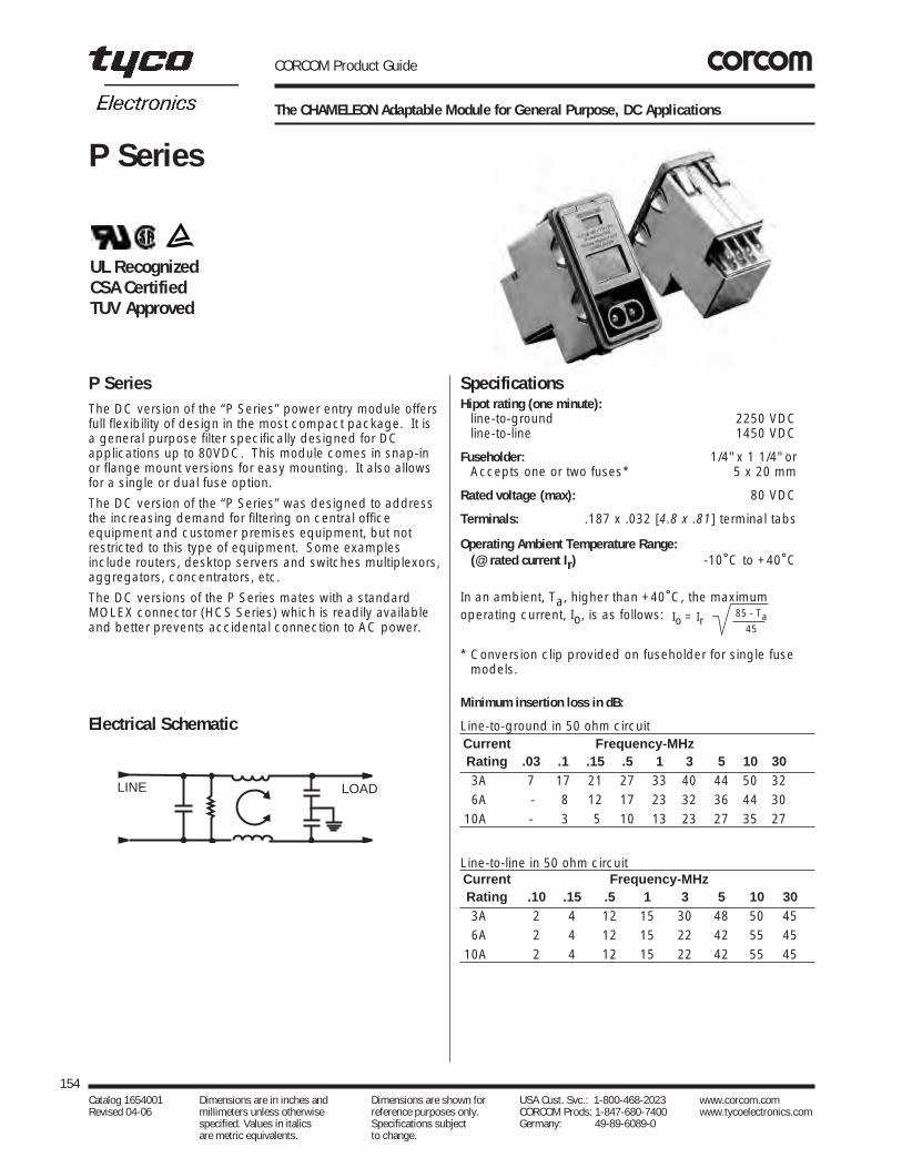
CORCOM Product Guide
154Catalog 1654001 Dimensions are in inches and Dimensions are shown for USA Cust. Svc.: 1-800-468-2023 www.corcom.com Revised 04-06 millimeters unless otherwise reference purposes only. CORCOM Prods: 1-847-680-7400 www.tycoelectronics.com
specified. Values in italics Specifications subject Germany: 49-89-6089-0 are metric equivalents. to change.
P Series
P Series
The CHAMELEON Adaptable Module for General Purpose, DC Applications
The DC version of the “P Series” power entry module offersfull flexibility of design in the most compact package. It isa general purpose filter specifically designed for DCapplications up to 80VDC. This module comes in snap-inor flange mount versions for easy mounting. It also allowsfor a single or dual fuse option.
The DC version of the “P Series” was designed to addressthe increasing demand for filtering on central officeequipment and customer premises equipment, but notrestricted to this type of equipment. Some examplesinclude routers, desktop servers and switches multiplexors,aggregators, concentrators, etc.
The DC versions of the P Series mates with a standardMOLEX connector (HCS Series) which is readily availableand better prevents accidental connection to AC power.
Minimum insertion loss in dB:
Line-to-ground in 50 ohm circuitCurrent Frequency-MHzRating .03 .1 .15 .5 1 3 5 10 3003A 7 17 21 27 33 40 44 50 320 6A - 8 12 17 23 32 36 44 3010A - 3 5 10 13 23 27 35 27
Line-to-line in 50 ohm circuitCurrent Frequency-MHzRating .10 .15 .5 1 3 5 10 30
0 3A 2 4 12 15 30 48 50 450 6A 2 4 12 15 22 42 55 4510A 2 4 12 15 22 42 55 45
SpecificationsHipot rating (one minute):
line-to-ground 2250 VDCline-to-line 1450 VDC
Fuseholder: 1/4" x 1 1/4" orAccepts one or two fuses* 5 x 20 mm
Rated voltage (max): 80 VDC
Terminals: .187 x .032 [4.8 x .81] terminal tabs
Operating Ambient Temperature Range:(@ rated current Ir) -10˚C to +40˚C
In an ambient, Ta, higher than +40˚C, the maximumoperating current, Io, is as follows:
* Conversion clip provided on fuseholder for single fuse models.
Electrical Schematic
UL RecognizedCSA CertifiedTUV Approved
LINE LOAD
85 - Ta45
Io = Ir

CORCOM Product Guide
The CHAMELEON Adaptable Module for General Purpose, DC Applications (Continued)
155Catalog 1654001 Dimensions are in inches and Dimensions are shown for USA Cust. Svc.: 1-800-468-2023 www.corcom.com Revised 04-06 millimeters unless otherwise reference purposes only. CORCOM Prods: 1-847-680-7400 www.tycoelectronics.com
specified. Values in italics Specifications subject Germany: 49-89-6089-0 are metric equivalents. to change.
DC
Filters
P SeriesCase Styles
AB
C
F∅ .06 Min.
1.54
Case Dimensions
Part No. A B C D E F(max) (max) (max)
PE 1.980 2.130 2.310 1.120 2.201 1.57550.29 54.10 58.67 28.45 55.91 40.00
PS 1.240 2.130 2.310 1.120 2.201 —31.50 54.10 58.67 28.45 55.91
Part Numbers
PE000DD3D PS000DD3DPE000DD6D PS000DD6DPE000DDXD PS000DDXDPE000SD3D PS000SD3DPE000SD6D PS000SD6DPE000SDXD PS000SDXD
DC Connector No. GA210
PE
AB
C
PS
Recommended Panel Cutout
+.008/-.000+.20/-.00
+.008/-.000+.20/-.00
Ordering Information
Mounting Style
E = Mounting earsS = Snap-in
Extender Options 0 = None
Switch Options0 = No switch
Input Voltage Select0 = Single voltage
Fuse OptionsD = Dual fuseS = Single fuse
Shield Options D = Complete shield
(DC version)Filter Current 3 = 3 amps6 = 6 ampsX = 10 amps
Filter TypeD = DC version
P S 0 0 0 D D 3 D
D
E
.061.52
R Max.
.020
.508R Min.
External Edge(1)
Note: The externaledges (installation side)on the "D" sides of the cutout should have aminimum .020" radius.For optional retentionagainst extraction, thecorresponding inneredge should be sharp,without paint or coatings.Edge coatings, includinganodization are also discouraged for goodshield contact.
Mating Connectors
CORCOM Part Number:
GA210 - Custom connector assembly with 2, 36” long 18
gauge wires to mate with P Series filter
MOLEX Component Part Numbers:
03-12-1026 Connector housing to mate with P Series
18-12-1222 Female Terminal (2 needed per housing)
Red
Black

CORCOM Product Guide
156
Engineering Notes
Catalog 1654001 Dimensions are in inches and Dimensions are shown for USA Cust. Svc.: 1-800-468-2023 www.corcom.com Revised 04-06 millimeters unless otherwise reference purposes only. CORCOM Prods: 1-847-680-7400 www.tycoelectronics.com
specified. Values in italics Specifications subject Germany: 49-89-6089-0 are metric equivalents. to change.

Introduction . . . . . . . . . . . . . . . . . . . . . . . . . . . . . . . . . . . . . . . . . . . . . . . . . . . . . . . . . . . .158SIGNAL SENTRY Filtered Modular Jacks . . . . . . . . . . . . . . . . . . . . . . . . . . . . . . . . . . . . .159SIGNAL SENTRY Filtered Modular Jacks Selector Chart . . . . . . . . . . . . . . . . . . . . . . . . .160RJ Jack Part Number Matrix . . . . . . . . . . . . . . . . . . . . . . . . . . . . . . . . . . . . . . . . . . . . . . .161BLF Series . . . . . . . . . . . . . . . . . . . . . . . . . . . . . . . . . . . . . . . . . . . . . . . . . . . . . . . . . . . .162L Series . . . . . . . . . . . . . . . . . . . . . . . . . . . . . . . . . . . . . . . . . . . . . . . . . . . . . . . . . . . . . . .163L Series - Ganged . . . . . . . . . . . . . . . . . . . . . . . . . . . . . . . . . . . . . . . . . . . . . . . . . . . . . . .164LC Series . . . . . . . . . . . . . . . . . . . . . . . . . . . . . . . . . . . . . . . . . . . . . . . . . . . . . . . . . . . . . .165LCT Series . . . . . . . . . . . . . . . . . . . . . . . . . . . . . . . . . . . . . . . . . . . . . . . . . . . . . . . . . . . . .166N Series . . . . . . . . . . . . . . . . . . . . . . . . . . . . . . . . . . . . . . . . . . . . . . . . . . . . . . . . . . . . . . .167X Series . . . . . . . . . . . . . . . . . . . . . . . . . . . . . . . . . . . . . . . . . . . . . . . . . . . . . . . . . . . . . . .168Z Series . . . . . . . . . . . . . . . . . . . . . . . . . . . . . . . . . . . . . . . . . . . . . . . . . . . . . . . . . . . . . . .169Model Dimensions . . . . . . . . . . . . . . . . . . . . . . . . . . . . . . . . . . . . . . .170, 171, 172, 173, 174
CORCOM Product Guide
Signal Line Products — Table of Contents
157Catalog 1654001 Dimensions are in inches and Dimensions are shown for USA Cust. Svc.: 1-800-468-2023 www.corcom.com Revised 04-06 millimeters unless otherwise reference purposes only. CORCOM Prods: 1-847-680-7400 www.tycoelectronics.com
specified. Values in italics Specifications subject Germany: 49-89-6089-0 are metric equivalents. to change.
SignalLineProducts

CORCOM Product Guide
158Catalog 1654001 Dimensions are in inches and Dimensions are shown for USA Cust. Svc.: 1-800-468-2023 www.corcom.com Revised 04-06 millimeters unless otherwise reference purposes only. CORCOM Prods: 1-847-680-7400 www.tycoelectronics.com
specified. Values in italics Specifications subject Germany: 49-89-6089-0 are metric equivalents. to change.
Introduction
CORCOM SIGNAL SENTRY Filtered Modular Jack seriesproduct combines different levels of filtering with RJ45and RJ11 modular jacks as well as surface mountablefilters to solve signal line noise problems and crosstalk.
CORCOM SIGNAL SENTRY Filtered Modular Jackseries product has expanded into 80 differentproducts for filtering the signal line, includinginductor and capacitor, shielded, ganged, low profileand surface mountable versions. Designs not onlysave valuable panel space, but also place thefiltering elements where they can be most effective ineliminating RFI.
This section is divided by series, starting with ournewest product, the BLF series. The BLF, our firstsurface mountable filter, filters two lines with one part.Available in either an 82pF or an 820pF version, theBLF can withstand 1000VAC dielectric voltage for 60seconds, allowing placement of the filter immediatelybehind the connector.
The L and N series RJ11 and RJ45 jacks offerfiltering with inductance and optional shielding, whilethe LC and LCT series combine inductance with82pF or 820pF capacitors. The X and Z seriescomplete the offering with unfiltered versions of ourstandard profile and low profile jacks.
Use the selector chart to combine your filteringperformance with the RJ11 or RJ45 jacks.Mechanical dimensions are listed following the seriesinformation.
For the latest information and additional technicalarticles, find CORCOM products on the Internet athttp://www.corcom.com.

CORCOM Product Guide
SIGNAL SENTRY Filtered Modular Jacks
159Catalog 1654001 Dimensions are in inches and Dimensions are shown for USA Cust. Svc.: 1-800-468-2023 www.corcom.com Revised 04-06 millimeters unless otherwise reference purposes only. CORCOM Prods: 1-847-680-7400 www.tycoelectronics.com
specified. Values in italics Specifications subject Germany: 49-89-6089-0 are metric equivalents. to change.
SignalLineProducts
CORCOM SIGNAL SENTRY Filtered Modular Jacks isa space saving and cost effective solution to RFIproblems on signal lines. Its inductive and optionalcapacitive elements effectively strip common-modenoise from the incoming signal, and at the same timelimit the signal line’s ability to radiate emissions likean antenna.
The SIGNAL SENTRY Filtered Modular Jack serieshas expanded into 80 different products for filteringthe signal line, including inductor and capacitor,shielded, ganged, low profile and surface mountableversions. Filtered RJ jacks provide interferencesuppression at the optimal location by integrating thefiltering into the RJ jack itself. Our new ganged jacksare the only RJ11 filtered ganged jacks available inthe market. The surface mountable BLF series filterstwo lines with one part and can withstand 1000VACdielectric voltage, allowing placement of the filterimmediately behind the connector.
SIGNAL SENTRY Filtered Modular Jack products areuseful for any electronic equipment that sends orreceives data on unshielded twisted pair or othermulti-conductor cabling systems. Modems, PBX’s,LAN, ISDN, and local I/O interfaces that use RJconnectors are all candidates.
Jack design and component selection compatible withequipment registered under FCC Part 68. UL Recognized. CSA Certified.
A FAX/Modem board was being certified for FCC Class B emissions atan independent test laboratory. Theboard caused every computer it wastested in to exceed the radiated limitsabove 30 MHz, at multiples of eachmicroprocessor’s clock frequency, onthe telephone line. The test lab replaced the modem’sunfiltered RJ11 jack with a CORCOM RJ11-4L-B FilteredModular Jack out of their sample kit, and the board/computer combinations passed with 4 dB margin worst case.
An RISC workstation designed to operate in a twisted-pair Local AreaNetwork required two DIP packageinductors and 12 chip capacitors tomeet FCC radiated emissions limits. All14 discrete components were eliminatedby replacing the two RJ45 connectors
with two CORCOM RJ45-8LC1-B shielded and filteredjacks, and the margin of compliance actually improved.
A secure telephone set failed TEMPEST testing at a government facil-ity, due to intelligible emanations radi-ated from the coiled handset cord.The unit passed after the handset connector in the desk set was replacedby a CORCOM RJH-4L-B filtered
A medical manufacturer was designinga heart monitor which would transferdata over a signal line to the nurses’ sta-tion so they could monitor patients.When the doctors used their modems,the data coming from the monitorbecame distorted. This occurred due to
the close proximity of the modem card and monitor com-munication card placed next to each other. A CORCOMlow profile RJ45-8N3-B modular jack was designed in to filter out the unwanted noise.
Applications

CORCOM Product Guide
160Catalog 1654001 Dimensions are in inches and Dimensions are shown for USA Cust. Svc.: 1-800-468-2023 www.corcom.com Revised 04-06 millimeters unless otherwise reference purposes only. CORCOM Prods: 1-847-680-7400 www.tycoelectronics.com
specified. Values in italics Specifications subject Germany: 49-89-6089-0 are metric equivalents. to change.
SIGNAL SENTRY Filtered Modular Jacks Selector Chart
Level of
Filtering
No
No
Yes
YesInductor Only
Inductor and Capacitor
Try the:X
SeriesStandard ProfileModular Jack
Page 168
BLFSeries
820pF and 82pFBoard Level Filter
Page 162
ZSeries
Low ProfileModular Jack
Page 169
NSeries
Low ProfileModular Jack
Page 167
Try the:L
SeriesStandard ProfileModular Jack
Page 163
Try the:LC
Series820pF
Modular JackPage 165
LCTSeries
82pFModular Jack
Page 166
Filtered
Ganged
Try the:
LSeries
GangedPage 164

CORCOM Product Guide
161Catalog 1654001 Dimensions are in inches and Dimensions are shown for USA Cust. Svc.: 1-800-468-2023 www.corcom.com Revised 04-06 millimeters unless otherwise reference purposes only. CORCOM Prods: 1-847-680-7400 www.tycoelectronics.com
specified. Values in italics Specifications subject Germany: 49-89-6089-0 are metric equivalents. to change.
SignalLineProducts
RJ Jack Part Number Matrix
HOW MANY TERMINALS WILL BE LOADED? (See below)
4 on RJH2, 4 or 6 on RJ116 or 8 on RJ45
WHAT LEVEL OF FILTERING PERFORMANCE DO YOU NEED?
No filter, standard profile X modelsInductor (block or sleeve), standard profile L modelsInductor plus capacitors with shield LC modelsInductor, 82 pF cap. and shield LCT modelInductor (block or sleeve), low profile N modelsNo filter, low profile Z models
DO YOU WANT A SHIELDED JACK? (Optional on L, X, N, Z models, required on LC or LCT.)
WHAT TYPE OF GROUND?
*Panel and board ground (spring fingers on panel interface) 1*Board ground pins only 2†Panel, board and cable ground (low profile versions) 3†Board ground and cable ground (low profile versions) 4*Panel, board ground and cable ground (standard profile versions) 5*Board ground and cable ground (standard profile versions) 6
WHAT TYPE OF INDUCTORS DO YOU NEED?
Sleeve — Average performance SBlock — Higher performance B
Sleeve inductance is recommended in cases where crosstalk may be a problem.
WHAT TYPE OF CONNECTOR DO YOU NEED?
Handset jack four pin connector RJHRJ11 six pin connector RJ11RJ45 eight pin connector RJ45
RJ11-4L1-B
RJ11-4L1-B
RJ11-4L1-B
RJ11-4L1-B
RJ11-4L1-B
RJ11 Model Contact Loading Program RJ45 Model Contact Loading Program
* L, LC, LCT, X models† N, Z models
RJ11-2 + +
RJ11-4 + + + +
RJ11-6 + + + + + +
Lead Frame PositionJack Designation 1 2 3 4 5 6
RJ45-6 + + + + + +
RJ45-8 + + + + + + + +
Lead Frame PositionJack Designation 1 2 3 4 5 6 7 8
1 12 23 34 4 55 6 6 7 8

Tyco Electronics introduces a new line of surfacemountable RFI filters specifically designed to eliminatenoise on the signal line. These board level filters attenuatenoise on the signal line at the frequency range of 10 MHz to 1000 MHz with maximum attenuation at 40 MHz to 400MHz.
The U shaped ferrite features a parallel first and second legwith a center leg surrounded by a grounding/shorting strapand a capacitor for each line. This unique designoptimizes the filter performance by combining the elementsinto one low profile single piece filter. Each filter acts ontwo signal lines, but can be stacked as an array to allowperformance over multiple lines.
The BLF filter can withstand dielectric voltage of 1000 VACfor 60 seconds, thereby allowing placement of this filter atthe optimal location, immediately behind the connector.This placement allows immunity protection from signal lineinterference as well as significant reduction of RFIemissions. The filter can be used in conjunction withunfiltered RJ jacks, ganged jacks, or with filtered modularjacks for additional protection.
CORCOM Product Guide
Surface Mountable RFI Filters
Capacitors:
Type Monolithic ceramic chipStandard Value:
BLF820 820pFBLF082 82pFStandard Tolerance: +/-20%
Ferrites:
Type: High resistivity, nickel zinc ceramicInductance: 2 µH
Housing Material: Glass-filled polyester (UL94V-0)
Dielectric Withstanding Voltage:Line-to-line and line-to-ground 1000 VAC for
60 seconds
Ratings: 2.2 Amps max.56.6 Volts max.
162Catalog 1654001 Dimensions are in inches and Dimensions are shown for USA Cust. Svc.: 1-800-468-2023 www.corcom.com Revised 04-06 millimeters unless otherwise reference purposes only. CORCOM Prods: 1-847-680-7400 www.tycoelectronics.com
specified. Values in italics Specifications subject Germany: 49-89-6089-0 are metric equivalents. to change.
BLF Series
BLF Series
Specifications
Electrical Schematic
Pass Band Minimum insertion loss in dB:Differential mode in a 50 ohm circuit
at 1 MHz <1dBat 5MHz < 6dB
Stop Band Minimum insertion loss in dB:Common mode in a 50 ohm circuit
Current Frequency-MHzRating 20 40 70 100 150 300 500 700 1000
BLF082 4 10 16 20 25 40 26 23 20BLF820 20 30 40 50 40 31 25 22 13
Part Numbers
BLF820BLF082
UL Recognized
Dimensions
LINE LOAD
.256.35
Gnd Pad
(4 places)
Recommended Pad Layout
Max. .45011.43
Max.
.3759.53
Max.
.1002.54
.1002.54
.1503.81
.2656.73
Max.
.1203.05
.0501.27
.0471.19
(2 places)
.0471.19
BLF

CORCOM Product Guide
Inductive Filtering Modular RJ Jacks
163Catalog 1654001 Dimensions are in inches and Dimensions are shown for USA Cust. Svc.: 1-800-468-2023 www.corcom.com Revised 04-06 millimeters unless otherwise reference purposes only. CORCOM Prods: 1-847-680-7400 www.tycoelectronics.com
specified. Values in italics Specifications subject Germany: 49-89-6089-0 are metric equivalents. to change.
SignalLineProducts
L Series
Inductive filtering in a direct retrofit to standard unfilteredRJ11, RJ45, or handset jacks. Offered with standard ferritesleeve inductors or higher performance ferrite blocks, the Lseries is available with or without a shield.
L Series
Contacts:
Material: Phosphor BronzePlating: 50 microinches goldBarrier underplating: 100 microinches nickelResistance:Initial: 20 milliohms max.After durability testing: 30 milliohms max.(500 mating cycles)
Ferrites:
Type: High resistivity, nickel zinc ceramicSleeves: Single-aperture cylindersBlock: Multi-aperture rectangular prism
Shield Material: Tin-plated copper alloy
Housing Material: Glass-filled polyester (UL94V-0)
Dielectric Withstanding Voltage:Line-to-line and line-to-ground 1000 VAC for
60 seconds
Printed Circuit Board Retention:Before soldering: 1 lb. minimumAfter soldering: 20 lb. minimum
Model dimensions and PC board layout on pages 170 to 174.
Specifications
150
140
130
120
110
100
90
80
70
60
50
40
30
20
10
01 25 100 200 500
Frequency in MHz
Impe
danc
ein
Ohm
s
Typical Impedance in Ohms
Part NumbersInductor FilterRJH-4L-B RJ45-6L-SRJ11-2L-S RJ45-6L-BRJ11-2L-B RJ45-8L-SRJ11-4L-S RJ45-8L-BRJ11-4L-BRJ11-6L-SRJ11-6L-B
Inductor Filter and ShieldRJ11-2L2-B RJ45-6L1-SRJ11-4L1-S RJ45-6L1-BRJ11-4L1-B RJ45-6L2-SRJ11-4L2-S RJ45-6L2-BRJ11-4L2-B RJ45-8L1-SRJ11-6L1-S RJ45-8L1-BRJ11-6L1-B RJ45-8L2-SRJ11-6L2-S RJ45-8L2-BRJ11-6L2-B
See page 167 for the CORCOM new low profile RJ Jacks.
Shield 2 Shield 1
UL RecognizedCSA Certified
RJ11 RJ11 withBlock Filter
RJ45 withSleeve Filter
RJ45

CORCOM Product Guide
L Series - Ganged Version
Ganged version of our L series filtered jacks. Available inRJ11 models with block inductors in gangs of 2, 4, or 6.Retrofits existing unfiltered ganged jack footprints.
Specifications
Contacts:
Material: Phosphor BronzePlating: 50 microinches goldBarrier underplating: 100 microinches nickelResistance:Initial: 20 milliohms max.After durability testing: 30 milliohms max.(500 mating cycles)
Ferrites:
Type: High resistivity, nickel zinc ceramicBlock: Multi-aperture rectangular prism
Housing Material: Glass-filled polyester (UL94V-0)
Dielectric Withstanding Voltage:Line-to-line and line-to-ground 1000 VAC for
60 seconds
Printed Circuit Board Retention:Before soldering: 1 lb. minimumAfter soldering: 20 lb. minimum
164Catalog 1654001 Dimensions are in inches and Dimensions are shown for USA Cust. Svc.: 1-800-468-2023 www.corcom.com Revised 04-06 millimeters unless otherwise reference purposes only. CORCOM Prods: 1-847-680-7400 www.tycoelectronics.com
specified. Values in italics Specifications subject Germany: 49-89-6089-0 are metric equivalents. to change.
L - Ganged Series
L - Ganged Series
Part Numbers
2RJ11-6L-B4RJ11-6L-B6RJ11-6L-B
150
140
130
120
110
100
90
80
70
60
50
40
30
20
10
01 25 100 200 500
Frequency in MHz
Impe
danc
ein
Ohm
s
Typical Impedance in Ohms
Model Dimensions and PC Board Layout.0501.27
.250 [6.35]
.350 [8.89]
.030+ .008 - .003 Dia.
A
B
C
.128 + .003 Dia.
.47011.94
D
.3258.25
.1002.54.050 [1.27]
.195
.0401.02
.81020.57
.41010.41
.1654.19
.59014.99
Ports A B C D
2 .99 .87 .795 .8725.15 22.1 20.19 22.1
4 1.93 1.81 1.735 1.8149.02 45.97 44.07 25.97
6 2.87 2.75 2.675 2.7572.9 69.85 67.95 69.85
L - Ganged Series
6RJ11
4RJ11
2RJ11 with Block Filter
UL RecognizedCSA Certified

CORCOM Product Guide
Filtered Modular Jacks with Enhanced Performance
165Catalog 1654001 Dimensions are in inches and Dimensions are shown for USA Cust. Svc.: 1-800-468-2023 www.corcom.com Revised 04-06 millimeters unless otherwise reference purposes only. CORCOM Prods: 1-847-680-7400 www.tycoelectronics.com
specified. Values in italics Specifications subject Germany: 49-89-6089-0 are metric equivalents. to change.
SignalLineProducts
LC Series
Capacitance components enhance the filteringperformance in the LC models. Available with block orsleeve inductance, the additional chip capacitors provideadditional filtering on each line. The series features shieldswith a board ground or spring finger panel interface.
Specifications
Contacts:
Material: Phosphor BronzePlating: 50 microinches goldBarrier underplating: 100 microinches nickelResistance:Initial: 20 milliohms max.After durability testing: 30 milliohms max.(500 mating cycles)
Capacitors:
Type: Monolithic ceramic chipStandard value: 820 pFStandard tolerance: ±20%
Ferrites:Type: High resistivity, nickel zinc ceramicSleeves: Single-aperture cylindersBlock: Multi-aperture rectangular prism
Shield Material: Tin-plated copper alloy
Housing Material: Glass-filled polyester (UL94V-0)
Dielectric Withstanding Voltage:Line-to-line and line-to-ground 1000 VAC for
60 seconds
Printed Circuit Board Retention:Before soldering: 1 lb. minimumAfter soldering: 20 lb. minimum
Model dimensions and PC board layout on pages 170 to 174.
LC Series
Typical insertion loss in dB:Line-to-ground (stop band) in a 50 ohm circuit
Frequency-MHz30 60 80 100 200 500 1000
Ferrite 28 40 51 40 27 24 22SleevesFerrite 30 41 59 40 31 28 24Blocks
Typical insertion loss in dB:Line-to-line (pass band) in a 50 ohm circuit
Frequency-MHz2 5 10 30 50 70 100
Ferrite 4 8 18 24 30 40SleevesFerrite 1 8 11 21 28 33 37Blocks
Part Numbers
RJ11-2LC1-S RJ11-6LC2-SRJ11-2LC1-B RJ11-6LC2-BRJ11-2LC2-S RJ45-6LC1-SRJ11-2LC2-B RJ45-6LC1-BRJ11-4LC1-S RJ45-6LC2-SRJ11-4LC1-B RJ45-6LC2-BRJ11-4LC2-S RJ45-8LC1-SRJ11-4LC2-B RJ45-8LC1-BRJ11-6LC1-S RJ45-8LC2-SRJ11-6LC1-B RJ45-8LC2-B
UL RecognizedCSA Certified
Shield 2RJ11
Shield 1RJ11
Shield 2RJ45
Shield 1RJ45

CORCOM Product Guide
Low Capacitance Modular RJ Jacks
166Catalog 1654001 Dimensions are in inches and Dimensions are shown for USA Cust. Svc.: 1-800-468-2023 www.corcom.com Revised 04-06 millimeters unless otherwise reference purposes only. CORCOM Prods: 1-847-680-7400 www.tycoelectronics.com
specified. Values in italics Specifications subject Germany: 49-89-6089-0 are metric equivalents. to change.
LCT Series
Capacitance components enhance the filteringperformance but may alter the signal as it passes throughthe RJ Jack. A low capacitance model allows additionalfilter performance without significant effect on the signalitself. The new LCT models provide improved performanceover L models without impact on the signal. These partsare particularly suited for ethernet applications.
These models are available in shielded models only, witheither panel or board ground.
Specifications
Contacts:
Material: Phosphor BronzePlating: 50 microinches goldBarrier underplating: 100 microinches nickelResistance:Initial: 20 milliohms max.After durability testing: 30 milliohms max.(500 mating cycles)
Capacitors:
Type: Monolithic ceramic chipStandard value: 82 pFStandard tolerance: ±20%
Ferrites:Type: High resistivity, nickel zinc ceramicSleeves: Single-aperture cylindersBlock: Multi-aperture rectangular prism
Shield Material: Tin-plated copper alloy
Housing Material: Glass-filled polyester (UL94V-0)
Dielectric Withstanding Voltage:Line-to-line and line-to-ground 1000 VAC for
60 seconds
Printed Circuit Board Retention:Before soldering: 1 lb. minimumAfter soldering: 20 lb. minimum
Model dimensions and PC board layout on pages 170 to 174.
LCT Series
Typical insertion loss in dB:Line-to-ground (stop band) in a 50 ohm circuit
Frequency-MHz40 100 200 250 300 500 1000
Ferrite 8 12 27 50 38 25 20SleevesFerrite 10 18 22 55 40 28 24Blocks
Typical insertion loss in dB:Line-to-line (pass band) in a 50 ohm circuit
Frequency-MHz2 5 10 30 50 70 100
Ferrite 1.2 1.9 4 5 7 10SleevesFerrite 1 2 3 5 8 10 13Blocks
Part Numbers
RJ11-6LCT1-S RJ45-8LCT1-SRJ11-6LCT1-B RJ45-8LCT1-BRJ11-6LCT2-S RJ45-8LCT2-S RJ11-6LCT2-B RJ45-8LCT2-B
UL RecognizedCSA Certified
Shield 2RJ11
Shield 1RJ11
Shield 2RJ45
Shield 1RJ45

CORCOM Product Guide
N Series — Low Profile Filtered Modular RJ Jack
167Catalog 1654001 Dimensions are in inches and Dimensions are shown for USA Cust. Svc.: 1-800-468-2023 www.corcom.com Revised 04-06 millimeters unless otherwise reference purposes only. CORCOM Prods: 1-847-680-7400 www.tycoelectronics.com
specified. Values in italics Specifications subject Germany: 49-89-6089-0 are metric equivalents. to change.
SignalLineProducts
N Series
Low profile version of our SIGNAL SENTRY FilteredModular Jack series. Available with sleeve or blockinductors and optional grounded shielding. Groundedshielding allows connection to grounded cables foradditional RFI protection.
SpecificationsContacts:
Material: Phosphor BronzePlating: 50 microinches goldBarrier underplating: 100 microinches nickelResistance:Initial: 20 milliohms max.After durability testing: 30 milliohms max.(500 mating cycles)
PCB Terminals:
Solderability 60/40
Ferrites:Type: High resistivity, nickel zinc ceramicSleeves: Single-aperture cylindersBlock: Multi-aperture rectangular prism
Shield Material: Tin-plated copper alloy
Housing Material: Black glass filled polyester (Valox 457)
Dielectric Withstanding Voltage:Line-to-line and line-to-ground 1000 VAC for
60 seconds
Printed Circuit Board Retention:Before soldering: 1 lb. minimumAfter soldering: 20 lb. minimum
Model dimensions and PC board layout on pages 170 to 174.
N Series
Part Numbers
RJ11-6N-B RJ45-8N-BRJ11-6N-S RJ45-8N-SRJ11-6N3-B RJ45-8N3-BRJ11-6N3-S RJ45-8N3-SRJ11-6N4-B RJ45-8N4-BRJ11-6N4-S RJ45-8N4-S
Shield 3RJ11
Shield 3 Unshielded
Shield 4RJ45
100
90
80
70
60
50
40
30
20
10
01 25 100 200 500 1000
Frequency in MHz
Impe
danc
ein
Ohm
s
Ferrite block Ferrite sleeve
Typical Impedance in Ohms
UL RecognizedCSA Certified

CORCOM Product Guide
X Series — Unfiltered Modular RJ Jack
SpecificationsContacts:
Material: Phosphor BronzePlating: 50 microinches goldBarrier underplating: 100 microinches nickelResistance:Initial: 20 milliohms max.After durability testing: 30 milliohms max.(500 mating cycles)
Shield Material: Tin Plated Copper Alloy
Housing Material: Glass-filled polyester (UL94V-0)(500 mating cycles)
Dielectric Withstanding Voltage:
Line-to-line and line-to-ground 1000 VAC for60 seconds
Printed Circuit Board Retention:
Before soldering: 1 lb. minimumAfter soldering: 20 lb. minimum
168Catalog 1654001 Dimensions are in inches and Dimensions are shown for USA Cust. Svc.: 1-800-468-2023 www.corcom.com Revised 04-06 millimeters unless otherwise reference purposes only. CORCOM Prods: 1-847-680-7400 www.tycoelectronics.com
specified. Values in italics Specifications subject Germany: 49-89-6089-0 are metric equivalents. to change.
X Series
X SeriesTyco Electronics offers a standard, unfiltered jack in boththe RJ45 and RJ11 models to complement our filtered line.
Shield 1 Shield 2
Part Numbers
RJ11-2X RJ45-6XRJ11-4X RJ45-8XRJ11-6X RJ45-8X1
RJ45-8X2
Model dimensions and PC board layout on pages 170 to 174.
UL RecognizedCSA Certified RJ45 RJ11

SpecificationsContacts:
Material: Phosphor BronzePlating: 50 microinches goldBarrier underplating: 100 microinches nickelResistance:Initial: 20 milliohms max.After durability testing: 30 milliohms max.(500 mating cycles)
PCB Terminals:
Solderability 60/40
Shield Material: Tin-plated phosphor bronze
Housing Material: Black glass-filled polyester(Valox 457)
Dielectric Withstanding Voltage:
Line-to-line and line-to-ground 1000 VAC for60 seconds
Printed Circuit Board Retention:
Before soldering: 1 lb. minimumAfter soldering: 20 lb. minimum
Model dimensions and PC board layout on pages 170 to 174.
Z SeriesUnfiltered low profile jack in RJ11 and RJ45 models.Shielded and unshielded models available.
Part Numbers
RJ11-6Z RJ45-8ZRJ11-6Z3 RJ45-8Z3RJ11-6Z4 RJ45-8Z4
Shield 3RJ11
Shield 4RJ45
UL Recognized
CORCOM Product Guide
Z Series — Low Profile Unfiltered Modular Jack
169Catalog 1654001 Dimensions are in inches and Dimensions are shown for USA Cust. Svc.: 1-800-468-2023 www.corcom.com Revised 04-06 millimeters unless otherwise reference purposes only. CORCOM Prods: 1-847-680-7400 www.tycoelectronics.com
specified. Values in italics Specifications subject Germany: 49-89-6089-0 are metric equivalents. to change.
SignalLineProducts
Z Series

CORCOM Product Guide
170Catalog 1654001 Dimensions are in inches and Dimensions are shown for USA Cust. Svc.: 1-800-468-2023 www.corcom.com Revised 04-06 millimeters unless otherwise reference purposes only. CORCOM Prods: 1-847-680-7400 www.tycoelectronics.com
specified. Values in italics Specifications subject Germany: 49-89-6089-0 are metric equivalents. to change.
Model Dimensions
RJ11 (Style 1 Shield)
RJ11 (Style 2 Shield)
Standard Profile RJ Jack DimensionsFor the L, LC, LCT and X Series of RJ Jack Filters
RJ11 (PC Board Layout)
6
4
2
5
3
1
.84021.34
.78019.81
.1954.95
.1654.19
.54013.72
.48512.32
.3228.18
.1654.19
.90022.86.860
21.84
.041.02
RJ11 (No Shield)
6
4
2
5
3
1
.62015.75.520
13.21
.59014.99
.1954.95
.1654.19
.3228.19
.39510.03
.52013.21
.81020.57
.0401.02
Part NumbersRJ11-2LC1-SRJ11-4LC1-SRJ11-6LC1-S
RJ11-2LC1-BRJ11-4LC1-BRJ11-6LC1-B
RJ11-4L1-SRJ11-6L1-SRJ11-4L1-B
RJ11-6L1-BRJ11-6LCT1-SRJ11-6LCT1-B
6
4
2
5
3
1
.78019.81
.1954.95
.54013.72
.90022.86.800
20.32
.48512.32
.3228.18
.1654.19
.1654.19
.041.02
Part NumbersRJ11-2LC2-SRJ11-4LC2-SRJ11-6LC2-S
RJ11-2LC2-BRJ11-4LC2-BRJ11-6LC2-B
RJ11-4L2-SRJ11-6L2-SRJ11-4L2-B
RJ11-6L2-BRJ11-6LCT2-SRJ11-6LCT2-B
Part NumbersRJ11-2L-S RJ11-2L-B RJ11-2XRJ11-4L-S RJ11-4L-B RJ11-4XRJ11-6L-S RJ11-6L-B RJ11-6X
With shield.3508.89
.40010.16
.0751.91
¯.128±.003 3.25±.08
(2 holes)
¯.030 +.008/-.003 .76 +.20/-.08
(6 places)
Edg
eof
Boa
rd
2
4
6
1
3
5
.0751.91
.2105.33
.3458.76
.0501.27
(5 spaces)
Dia.
.076±.0031.93± .08
(4 places)
Dia..2506.35
.2175.51
For all RJ11 L, LC, LCT and X Series Models
Shown from Component Side

CORCOM Product Guide
171Catalog 1654001 Dimensions are in inches and Dimensions are shown for USA Cust. Svc.: 1-800-468-2023 www.corcom.com Revised 04-06 millimeters unless otherwise reference purposes only. CORCOM Prods: 1-847-680-7400 www.tycoelectronics.com
specified. Values in italics Specifications subject Germany: 49-89-6089-0 are metric equivalents. to change.
SignalLineProducts
7
5
3
1
8
6
4
2
.78019.81
.1954.95
.1654.19
.1654.19
.62015.75
.48512.32
.3228.18
.80020.32
.90022.86
.041.02
Model Dimensions (Continued)
Standard Profile RJ Jack Dimensions (cont'd)
For the L, LC, LCT and X Series of RJ Jack Filters
RJ45 (Style 2 Shield)
RJ45 (PC Board Layout)
RJ45 (No Shield)
7
5
3
1
8
6
4
2
.70017.78.600
15.24
.54013.72
.1954.95
.041.02
.81020.57
.1654.19
.3228.18
.39510.03
Part NumbersRJ45-6LC2-SRJ45-6L2-SRJ45-8LCT2-S
RJ45-8LC2-SRJ45-8L2-SRJ45-8LCT2-B
RJ45-6LC2-BRJ45-6L2-B
RJ45-8LC2-BRJ45-8L2-B
Part NumbersRJ45-6LC2-SRJ45-6L2-SRJ45-8LCT2-B
RJ45-8LC2-SRJ45-8L2-SRJ45-8LCT2-S
RJ45-6LC2-BRJ45-6L2-B
RJ45-8LC2-BRJ45-8L2-B
Part NumbersRJ45-6L-SRJ45-8L-SRJ45-6L-B
RJ45-8L-BRJ45-6XRJ45-8X
.3228.18
.0501.27
(7 SPACES)
.3508.89
.030 +.008/.003.76 +.20/-.08
Dia.
(8 PLACES)
.128±.0033.25±.08
(4 PLACES)
(4 PLACES)
1
3
5
7
2
4
6
8
.2506.35
.45011.43
.2105.33
.3458.76
.0501.27
.0902.29
Dia.
.076±.0031.93±.08
Dia.
For all RJ45 L, LC, LCT and X Series Models.
Shown from Component Side
RJ45 (Style 1 Shield)
7
5
3
1
8
6
4
2
.92023.37
.78019.81
.1954.95
.041.02
.90022.86.860
21.84
.1654.19
.1654.19
.3228.18
.48512.32
.62015.75
Part NumbersRJ45-6LC1-SRJ45-6L1-SRJ45-8LCT1-S
RJ45-8LC1-SRJ45-8L1-SRJ45-8LCT1-B
RJ45-6LC1-BRJ45-6L1-BRJ45-8LC1-BRJ45-8L1-B

CORCOM Product Guide
Model Dimensions (Continued)
172Catalog 1654001 Dimensions are in inches and Dimensions are shown for USA Cust. Svc.: 1-800-468-2023 www.corcom.com Revised 04-06 millimeters unless otherwise reference purposes only. CORCOM Prods: 1-847-680-7400 www.tycoelectronics.com
specified. Values in italics Specifications subject Germany: 49-89-6089-0 are metric equivalents. to change.
RJH (No Shield).540
13.72
3
1
4
2
.44011.18
.59014.99
.1954.95
.3228.18
.3508.89
.2506.35
.39510.03
.81020.57
.041.02
Part NumbersRJH-4-L-B
Standard Profile RJ Jack Dimensions (cont'd)
For the L, LC, LCT and X Series of RJ Jack FiltersLow Profile RJ Jack DimensionsFor the N and Z Series of RJ Jack Filters
RJH (No Shield - PC Board Layout)
.3007.62
.128±.003 3.25±.08(2 holes)
Edg
eof
boar
d
1
32
4
.3228.18
.3508.89
.2506.35
.0751.91
.0501.27
(3 Spaces)
Dia.
Dia..030 +.008/-.003.76 +20/-.08
(4 holes)
Shown from Component Side
All tolerances ±0.010 [0.25] unless otherwise noted.
RJ11 (Low Profile - No Shield)
6
4
2
5
3
1
.62015.75
.1353.43
.71018.03
.1654.19
.2175.51
.40010.16
.52013.21
.010.25
.48512.32
.52013.21
Part NumbersRJ11-6N-B RJ11-6N-S RJ11-6Z
RJ11 Low Profile (Style 3 Shield)
6
4
2
5
3
1
.91023.11
.1654.19
.1353.43
.515*13.08
.010.25
.1203.05
.74018.80
.55013.97
.2175.51
.43010.92
Max.
Part NumbersRJ11-6N3-B RJ11-6N3-S RJ11-6Z3
*To top of shield
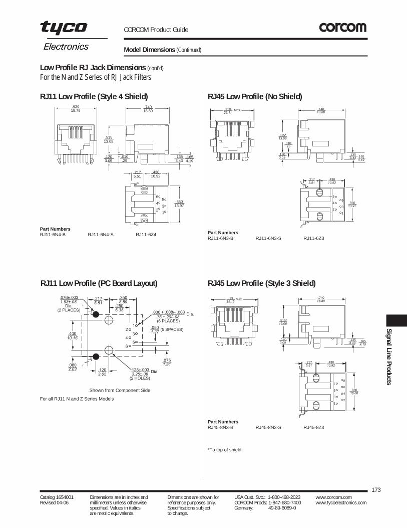
CORCOM Product Guide
Model Dimensions (Continued)
173Catalog 1654001 Dimensions are in inches and Dimensions are shown for USA Cust. Svc.: 1-800-468-2023 www.corcom.com Revised 04-06 millimeters unless otherwise reference purposes only. CORCOM Prods: 1-847-680-7400 www.tycoelectronics.com
specified. Values in italics Specifications subject Germany: 49-89-6089-0 are metric equivalents. to change.
SignalLineProducts
RJ45 Low Profile (No Shield)
RJ45 Low Profile (Style 3 Shield)
.9925.15
7
5
3
1
8
6
4
2
.1203.05
.74018.80
.1353.43
.43010.92
.2175.51
.63016.00
.165.4.19
.515*13.08
Max.
Part NumbersRJ45-8N3-B RJ45-8N3-S RJ45-8Z3
*To top of shield
RJ11 Low Profile (Style 4 Shield)
6
4
2
5
3
1
.91023.11
.1654.19
.1353.43
.515*13.08
.010.25
.1203.05
.74018.80
.55013.97
.2175.51
.43010.92
Max.
Part NumbersRJ11-6N3-B RJ11-6N3-S RJ11-6Z3
.62015.75
6
4
2
5
3
1
.51513.08
.74018.80
.1203.05
.010.25
.2175.51
.43010.92
.55013.97
.1353.43
.1654.19
Part NumbersRJ11-6N4-B RJ11-6N4-S RJ11-6Z4
Low Profile RJ Jack Dimensions (cont'd)
For the N and Z Series of RJ Jack Filters
RJ11 Low Profile (PC Board Layout)
.2175.51
(5 SPACES)
.030 + .008/- .003 Dia.
Dia.
(6 PLACES)
.1203.05
.128±.0033.25±.08
(2 HOLES)
.076±.0031.93±.08
Dia.(2 PLACES)
.0751.91
2
4
6
1
3
5
.3508.89
.0501.27
.2506.35
.76 +.20/-.08
.0802.03
.40010.16
Shown from Component Side
For all RJ11 N and Z Series Models

CORCOM Product Guide
Model Dimensions (Continued)
174Catalog 1654001 Dimensions are in inches and Dimensions are shown for USA Cust. Svc.: 1-800-468-2023 www.corcom.com Revised 04-06 millimeters unless otherwise reference purposes only. CORCOM Prods: 1-847-680-7400 www.tycoelectronics.com
specified. Values in italics Specifications subject Germany: 49-89-6089-0 are metric equivalents. to change.
Low Profile RJ Jack Dimensions (cont'd)
For the N and Z Series of RJ Jack Filters
RJ45 Low Profile (Style 4 Shield)
Part NumbersRJ45-8N4-B RJ45-8N4-S RJ45-8Z4
.70017.78
7
5
3
1
8
6
4
2
.515*13.08 .010
.25
.1654.19
.63016.00
.43010.92
.2175.51
.1353.43
.1203.05
.74018.80
RJ45 Low Profile (PC Board Layout)
.45011.43
Dia.
(8 Places)
.128±.003 3.25±.08
.076±.0031.93±.08 (2 Places)
1
3
5
7
2
4
6
8
.1203.05
.2175.51
.3508.89
.0501.27
.0501.27
.030 +.008/-.003.76 +.20/-.08
.2506.35
.0952.41
(7 Spaces)
(2 Places)
Dia.
Dia.
Shown from Component Side
For all RJ45 N and Z Series ModelsAll tolerances ±0.010 [0.25] unless otherwise noted.
*To top of shield

Introduction . . . . . . . . . . . . . . . . . . . . . . . . . . . . . . . . . . . . . . . . . . . . . . . . . . . . . . . . . . . .176Understanding RFI Power Line Filters . . . . . . . . . . . . . . . . . . . . . . . . . . . .177, 178, 179, 180Understanding Hipot Testing . . . . . . . . . . . . . . . . . . . . . . . . . . . . . . . . . . . . . . . . . . . . . .180Understanding Leakage Current . . . . . . . . . . . . . . . . . . . . . . . . . . . . . . . . . . . . . . . . . . .181Understanding Insertion Loss . . . . . . . . . . . . . . . . . . . . . . . . . . . . . . . . . . . . . . . . . .182, 183Appendix A- Conducted RFI Emissions Testing . . . . . . . . . . . . . . . . . . . . . . . . . . . . . . . .183Appendix B- Conducted RFI Susceptibility Testing . . . . . . . . . . . . . . . . . . . . . . . . . . . . .184Appendix C-UL 544 Health Care Equipment . . . . . . . . . . . . . . . . . . . . . . . . . . . . . . . . . .184Appendix D- Safety Agency File Numbers . . . . . . . . . . . . . . . . . . . . . . . . . . . . . . . . . . . .185Appendix E- Operating Ambient Temperature for RFI Power Line Filters . . . . . . . . . . . .185
CORCOM Product Guide
Technical Notes — Table of Contents
175Catalog 1654001 Dimensions are in inches and Dimensions are shown for USA Cust. Svc.: 1-800-468-2023 www.corcom.com Revised 04-06 millimeters unless otherwise reference purposes only. CORCOM Prods: 1-847-680-7400 www.tycoelectronics.com
specified. Values in italics Specifications subject Germany: 49-89-6089-0 are metric equivalents. to change.
TechnicalNotes

CORCOM Product Guide
176Catalog 1654001 Dimensions are in inches and Dimensions are shown for USA Cust. Svc.: 1-800-468-2023 www.corcom.com Revised 04-06 millimeters unless otherwise reference purposes only. CORCOM Prods: 1-847-680-7400 www.tycoelectronics.com
specified. Values in italics Specifications subject Germany: 49-89-6089-0 are metric equivalents. to change.
Introduction
Tyco Electronics has established itself as aworld leader in RFI technology by introducingthe first line of catalog filter products over 40years ago. Today, Tyco Electronics continues to pursue the latest in RFI filter design throughtesting and evaluating power supplies andstudying their effects.
Changing international standards obligatedesigners to constantly review and evaluatetheir filtering needs. The following section provides some basic information on RFIterminology and filter selection. Additional information can be accessed through TycoElectronics CORCOM internet pages athttp://www.corcom.com
CORCOM Product Guide
Understanding RFI Power Line Filters
What Is Radio Frequency Interference (RFI)?
RFI is unwanted electromagnetic energy in the frequencyrange generally used for radio communications. Thefrequency ranges of interest are 10kHz to 30MHz forconducted phenomena and 30MHz to 1GHz for radiatedphenomena.
What are the modes of propagation of RFI?
RFI is propagated via radiation (electromagnetic waves infree space) and by conduction over signal lines and ACpower systems.
Radiated - One of the most significant contributors toradiated RFI from electronic equipment is the AC powercord. The power cord is often an efficient antenna since its length approaches a quarter wave length for the RFIfrequencies present in digital equipment and switchingpower supplies.
Conducted - RFI is conducted over the AC powersystem in two modes. Common mode (asymmetrical)RFI is present on both the line and neutral current pathswith reference to the ground or earth path. Differen-tial mode (symmetrical) RFI is present as a voltagebetween the line and neutral leads.
Why Be Concerned with RFI?
The designers and manufacturers of digital equipmentmust concern themselves with RFI for two reasons. (1)Their equipment must operate properly in the applicationenvironment, often in the presence of significant levels ofRFI. (2) Their equipment must not emit RFI that interfereswith RF communications often vital to health and safety.The necessity for reliable RF communications has givenrise to legal regulations ensuring RFI control for electronicequipment.
What are the FCC requirements?
The U.S. Federal Communications Commission (FCC) hasestablished regulations to reduce the interference potentialof electronic computing devices (FCC Rules, Part 15,Subpart J). A computing device is defined as anyelectronic device or system that generates and uses timingsignals or pulses at a rate in excess of 10,000 per secondand that uses digital techniques. It is important to note thata switching power supply does not itself fall into thiscategory, but that its emissions must still meet the limitswhen it is installed in a piece of equipment that is subject tothe regulations.
The level of emissions the equipment must meet dependson whether it is marketed for use in a residentialenvironment (Class B) or in a commercial, industrial, orbusiness environment (Class A). The limits for Class B aremore stringent than those for Class A (see Appendix A).Most Class B equipment must undergo certification,meaning that emissions test data must be submitted to the
FCC for type approval. Class A and all other Class Bequipment must be verified—i.e. the manufacturerconducts his own emissions testing and verifies that hecomplies with the limits, but no forms need to be filed withthe FCC.
Further details on FCC requirements can be obtained fromthe FCC, RF Devices Branch (Authorization and StandardsDivision), Washington, DC 20554, (301) 725-1585.
What are CE markings and RFI filters?
As of January 1, 1996, electrical and electronic equipmentshipped to Europe is required to be labeled with the CEmarking. In order to apply the CE marking, equipmentmust meet the General Product Safety Directive andElectromagnetic Compatibility Directive.
RFI power line filters are components and therefore notcovered by the CE requirements, but they are used inelectronic systems to meet EMC specifications.
Two of the most common emission specifications are EN55011 for industrial, science, and medical equipment, andEN 55022 for information technology equipment. Theconducted emission limits for these specifications are thesame and broken down to Class “A” and Class “B” limits.Electronic equipment that may be connected to a powermain shared with a residential area must comply with themore stringent Class “B” limits. The measurementtechnique is done using quasi-peak and averagedetection, with different limits for each measure in dBabove one microvolt.
There are several immunity tests to which electronicequipment must comply, one of which is the electrically fast transient (EFT), IEC 61000-4-4. The equipment mustcontinue to operate during this test. The transient waveform is a 5ns rise time with a 50ns duration. A burst isinduced onto the power line at 1kV with a repetition rate of5kHz lasting 15ms and repeated every 300ms. The testsimulates switching of inductive loads and contacts.
To pass the EFT test, it is important that the RFI filter’senclosure have a good RF ground with the system’schassis ground. This provides a lower impedance pathfrom the safety ground to the system ground. Theshielding effect of the RFI filter’s metal enclosure eliminatesradiation into the system’s cabinet induced by theconducted EFT burst. Stray capacitance may occur fromany of the three input power wires to chassis ground wherevoltage can build up from the EFT burst and cause systeminterrupts. The RFI filter’s inductor offers an impedance tothe burst.
In cases where the stray capacitances have causedmultiple RF ground planes or where plastic enclosures areused, an inductive choke may be needed to provideisolation of the safety ground from the chassis ground.
177Catalog 1654001 Dimensions are in inches and Dimensions are shown for USA Cust. Svc.: 1-800-468-2023 www.corcom.com Revised 04-06 millimeters unless otherwise reference purposes only. CORCOM Prods: 1-847-680-7400 www.tycoelectronics.com
specified. Values in italics Specifications subject Germany: 49-89-6089-0 are metric equivalents. to change.
TechnicalNotes
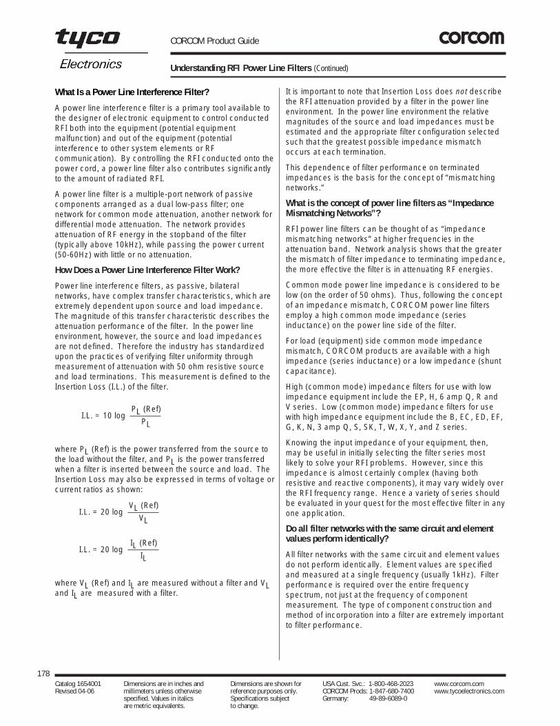
CORCOM Product Guide
Understanding RFI Power Line Filters (Continued)
It is important to note that Insertion Loss does not describethe RFI attenuation provided by a filter in the power lineenvironment. In the power line environment the relativemagnitudes of the source and load impedances must beestimated and the appropriate filter configuration selectedsuch that the greatest possible impedance mismatchoccurs at each termination.
This dependence of filter performance on terminatedimpedances is the basis for the concept of “mismatchingnetworks.”
What is the concept of power line filters as “ImpedanceMismatching Networks”?
RFI power line filters can be thought of as “impedancemismatching networks” at higher frequencies in theattenuation band. Network analysis shows that the greaterthe mismatch of filter impedance to terminating impedance,the more effective the filter is in attenuating RF energies.
Common mode power line impedance is considered to below (on the order of 50 ohms). Thus, following the conceptof an impedance mismatch, CORCOM power line filtersemploy a high common mode impedance (seriesinductance) on the power line side of the filter.
For load (equipment) side common mode impedancemismatch, CORCOM products are available with a highimpedance (series inductance) or a low impedance (shuntcapacitance).
High (common mode) impedance filters for use with lowimpedance equipment include the EP, H, 6 amp Q, R andV series. Low (common mode) impedance filters for usewith high impedance equipment include the B, EC, ED, EF,G, K, N, 3 amp Q, S, SK, T, W, X, Y, and Z series.
Knowing the input impedance of your equipment, then,may be useful in initially selecting the filter series mostlikely to solve your RFI problems. However, since thisimpedance is almost certainly complex (having bothresistive and reactive components), it may vary widely overthe RFI frequency range. Hence a variety of series shouldbe evaluated in your quest for the most effective filter in anyone application.
Do all filter networks with the same circuit and elementvalues perform identically?
All filter networks with the same circuit and element valuesdo not perform identically. Element values are specifiedand measured at a single frequency (usually 1kHz). Filterperformance is required over the entire frequencyspectrum, not just at the frequency of componentmeasurement. The type of component construction andmethod of incorporation into a filter are extremely importantto filter performance.
What Is a Power Line Interference Filter?
A power line interference filter is a primary tool available tothe designer of electronic equipment to control conductedRFI both into the equipment (potential equipmentmalfunction) and out of the equipment (potentialinterference to other system elements or RFcommunication). By controlling the RFI conducted onto thepower cord, a power line filter also contributes significantlyto the amount of radiated RFI.
A power line filter is a multiple-port network of passivecomponents arranged as a dual low-pass filter; onenetwork for common mode attenuation, another network fordifferential mode attenuation. The network providesattenuation of RF energy in the stopband of the filter(typically above 10kHz), while passing the power current(50-60Hz) with little or no attenuation.
How Does a Power Line Interference Filter Work?
Power line interference filters, as passive, bilateralnetworks, have complex transfer characteristics, which areextremely dependent upon source and load impedance.The magnitude of this transfer characteristic describes theattenuation performance of the filter. In the power lineenvironment, however, the source and load impedancesare not defined. Therefore the industry has standardizedupon the practices of verifying filter uniformity throughmeasurement of attenuation with 50 ohm resistive sourceand load terminations. This measurement is defined to theInsertion Loss (I.L.) of the filter.
where PL (Ref) is the power transferred from the source tothe load without the filter, and PL is the power transferredwhen a filter is inserted between the source and load. TheInsertion Loss may also be expressed in terms of voltage orcurrent ratios as shown:
where VL (Ref) and IL are measured without a filter and VLand IL are measured with a filter.
178Catalog 1654001 Dimensions are in inches and Dimensions are shown for USA Cust. Svc.: 1-800-468-2023 www.corcom.com Revised 04-06 millimeters unless otherwise reference purposes only. CORCOM Prods: 1-847-680-7400 www.tycoelectronics.com
specified. Values in italics Specifications subject Germany: 49-89-6089-0 are metric equivalents. to change.
I.L. = 10 logPL (Ref)
PL
I.L. = 20 logVL (Ref)
VL
I.L. = 20 logIL (Ref)
IL

CORCOM Product Guide
Understanding RFI Power Line Filters (Continued)
Figure 1 illustrates the high-frequency performancedifference between the three leaded capacitor constructionemployed by Tyco Electronics and a conventional methodof construction. Both units would be specified by the samenominal 1kHz component value, approximately 5000pF.
Figure 1: Insertion Loss
How Do You Select a Power Line Interference Filter?
The only way to select and qualify a power line interferencefilter is to test the unit in your equipment. As mentionedabove, the performance is highly dependent on equipmentload impedance. Filter performance cannot be derivedfrom single impedance (50 ohm) insertion loss data.Performance is a complex function of filter elementimpedances and equipment impedances which vary inmagnitude and phase over the frequency spectrum ofinterest. Filter selection testing should be performed inyour equipment to your required level of performance forboth conducted emission control (FCC, VDE) andsusceptibility control.
How do you perform conducted emission tests?
Conducted emission testing requires a quiet RFenvironment—usually a shielded enclosure—a lineimpedance stabilization network, and an RF voltageinstrument such as a tuned receiver or a spectrumanalyzer. Additional testing information is given inAppendix A. The RF ambient of the test environmentshould be at least 20 dB below the desired compliancelimit for accurate results. The line impedance stabilizationnetwork (LISN) is required to establish a desired sourceimpedance for the power line input. This is an importantpart of the test procedure, since this impedance directlyaffects the measured emission levels. The correctbandwidth for the measurement receiver is also a criticaltest parameter.
How do you perform susceptibility testing?
Susceptibility testing involves injection of noise onto thepower input lines while monitoring the equipment for properoperation. Quantification of the noise levels to be found inthe equipment environment is difficult at best. Throughanalysis of solutions to specific susceptibility problems,Tyco Electronics has developed recommended noiseinjection levels, which proved a high level of confidence forreliable equipment operation in the real world environment.The test methods and injection noise levels are found inAppendix B.
Is installation important to filter performance?
Mounting and wiring of the filter are critical influences on itsperformances. A power line filter is best installed at thepower line input point of your equipment. The filter is abarrier to high frequency signals. Its purpose must not bedefeated by stray capacitance coupling the power inputleads to the power output leads, or to any other conductorsin the protected equipment.
Normally the case of the filter is bolted to the framework orchassis of the electronic equipment it protects. The lineside leads should be kept short and well separated fromthe load side leads. The ideal isolation system is abulkhead-mounted filter incorporating a line cordconnector, such as the CORCOM EC, ED, or EF power linefilter series.
How Do You Know Which Filter To Test?
A filter, or ordered group of filters, likely to solve yourinterference control problem can be obtained by using theselector chart on pages 6 and 7. Every CORCOM filterseries is available in a range of current ratings andpackages. Detailed specifications, including prices, arelisted on the individual series’ catalog sheets referenced inthe selector chart. Telephone numbers of distributors whostock all Tyco Electronics products are listed on the backcover of this catalog.
Why Be Concerned with Safety Agency Requirements?
All components in the AC power system, including powerline filters, must be safe from potential fire and shockhazard. The standards set by the various safety agencies,like UL, CSA, VDE, and SEV, provide guidelines to assistthe designer in specifying safe and reliable components.Components which carry the compliance symbols fromthese agencies have been designed and manufactured tocomply with these standards. A summary of safety agencyrequirements can be found in Appendix C.
What are the significant requirements of UL and CSA?
UL and CSA are primarily concerned with high potentialwithstand capability, temperature rise, creepage distances,and material temperature capability at the time ofmanufacture.
179Catalog 1654001 Dimensions are in inches and Dimensions are shown for USA Cust. Svc.: 1-800-468-2023 www.corcom.com Revised 04-06 millimeters unless otherwise reference purposes only. CORCOM Prods: 1-847-680-7400 www.tycoelectronics.com
specified. Values in italics Specifications subject Germany: 49-89-6089-0 are metric equivalents. to change.
TechnicalNotes
010 20 30 40 50 60 70 80 90
100
Frequency MHz20.0 40.0 60.0
db V ConventionalConstruction
CORCOMConstruction

CORCOM Product Guide
Understanding RFI Power Line Filters (Continued)
Understanding Hipot Testing
The term “hipot” is an acronym for “high potential.” Hipottesting stresses the insulation and capacitors of a filterassembly by applying a voltage much higher than isusually experienced in normal operation. The purpose ofhipot specifications is to assure safety and reliability.
All the major safety agencies require hipot testing forqualification of power line filters, and also require that eachproduction unit undergo hipot testing to verify the integrityof the line-to-ground components and insulation. EveryCORCOM filter is hipot tested twice: once during assemblyand again after completion. Applying hipot testing as anincoming inspection procedure requires a thoroughunderstanding of its uses and limitations.
Hipot test voltages are applied from each line (both linestied together for VDE) to ground and from line-to-line. Theline-to-ground voltages are always higher. Test voltagesmay be specified as AC or DC, with the DC voltages atleast 1.414 times the AC voltages.
For incoming inspection testing, Tyco Electronicsrecommends using the voltages given as “hipot rating” foreach filter in the catalog. These DC voltages will always beequal to or higher than the peak AC voltage carried by anysafety agency whose approval the filter carries. A DC hipottest is generally used.
A variety of hipot testers is available from a number ofmanufacturers. The tester chosen should have at least a500VA rating.
The following precautions must be observed to insure thesafety of the operator and the validity of the test:
What are the additional aspects of VDE safetyrequirements?
In addition to the requirements of UL and CSA, VDEspecifies limits of hipot, insulation resistance, and changeof component values, at the conclusion of extremeenvironmental conditioning. The conditioning includes lifetests at elevated temperatures, long term humidity, andtemperature/humidity cycling. Components that bear theVDE symbol of safety have been designed and tested notonly for initial safety but also for safety over the life of theproduct.
How Do You Specify a Power Line Filter?
The filter you have selected through system testing canbest be specified by the data parameters found on theappropriate catalog page. Combining the product familyparameters listed under the “specifications” with thepackage style and dimensional data from your specificfilter will adequately define your selection.
180Catalog 1654001 Dimensions are in inches and Dimensions are shown for USA Cust. Svc.: 1-800-468-2023 www.corcom.com Revised 04-06 millimeters unless otherwise reference purposes only. CORCOM Prods: 1-847-680-7400 www.tycoelectronics.com
specified. Values in italics Specifications subject Germany: 49-89-6089-0 are metric equivalents. to change.
Are there other parameters that need to be specified?
There are three additional requirements that are oftenspecified. Below are our recommended values:
1. Insulation Resistance: 6000 M ohms @ 100VDC
2. Current Overload: 6 X rated current for 8 seconds
3. Humidity: 21 days at 40°C 95% RH
What are the test methods for verification of the importantspecification parameters?
Some filter specifications may be unfamiliar to you or mayrequire slightly different measuring techniques than youhave been using for other components. It is very importantthat supplier and customer use the same techniques forverification of electrical specifications, in order to assure anuninterrupted flow of quality components. Threespecifications that must be clearly understood are hipottesting, leakage current, and insertion loss.
1. THESE VOLTAGES CAN BE LETHAL—use the utmost safety precautions to protect the test operator.
2. The possibility of high surge currents and oscillatory overvoltage during sudden application of the test voltage requires some method of limiting the applied current or increasing the voltage comparatively slowly.
3. For AC hipot tests, use an oscillograph to monitor the applied voltage. The current limiting circuit may react with the filter circuit to distort the 60Hz waveform. This may produce a peak voltage that exceeds the expected peak value of a sinusoidal voltage having the specified rms value. The peak voltage should be 1.414 times the rms value. Higher voltages may cause unwarranted failures due to the peak currents exceeding the trip setting.
4. For line-to-line hipot testing, remember that most filters have a bleeder resistor (typical value 100kΩ to 10MΩ)to discharge the line-to-line capacitors. Be sure to set the trip point of the hipot tester above the current level that will flow through the bleeder resistor: 10mA is usually a safe value.

CORCOM Product Guide
Understanding Leakage Current
Leakage current is an important specification of power linefilters. There has always been an undeserved negativeconnotation to this term. Leakage current is not a functionof the quality of components, but is a direct function of theline-to-ground capacitance value. The larger thecapacitance, the lower the impedance to common modecurrents, and the greater the common mode interferencerejection. Hence, leakage current is a measure of filterperformance—the higher, the better.
Why, then, do safety agencies specify a maximumallowable leakage current? This is done in order to limit themagnitude of expected ground return currents. The line-to-ground capacitors provide a path for 50/60Hz current toflow to the chassis. As long as the equipment is grounded,these currents will flow in the ground circuit and present nohazard. However, in the unlikely but always possiblecircumstance where the ground circuit is faulty, the earthconnection may be established by the body of a person. If this should occur, the maximum leakage currentspecification limits the ground return current to a safevalue, typically 0.5 to 5.0mA. The limits set by safetyagencies are based on end user equipment specifications,such as those given below.
Capacitive Current Limits
Limits for Class ICountry Specification Grounded Equipment
U.S.A. UL 1950 3.5 mA, 120V, 60Hz
Canada C22.2 No. 950 3.5 mA, 120V, 60Hz
Europe EN 60950 3.5 mA, 250V, 50Hz
Since the largest component of leakage current is usuallyfrom the power line filter, it is prudent to set a maximumleakage current limit for the filter itself. There has been atendency in the industry to specify the minimum leakagecurrent to comply with all agency requirements, usually0.5mA. This specification decision should not be madearbitrarily, because often the size and cost of the filter canbe reduced by allowing a greater maximum leakagecurrent.
181Catalog 1654001 Dimensions are in inches and Dimensions are shown for USA Cust. Svc.: 1-800-468-2023 www.corcom.com Revised 04-06 millimeters unless otherwise reference purposes only. CORCOM Prods: 1-847-680-7400 www.tycoelectronics.com
specified. Values in italics Specifications subject Germany: 49-89-6089-0 are metric equivalents. to change.
TechnicalNotes
H
G
N
H
N
V
60HzACInputVoltage
H N
IsolationTransformer
VariacFilter
Under Test
No ConnectionTo LoadTerminals
1500
0.15
120V, 60Hzor
250V, 60Hz
f
Figure 2: Leakage Current Measurement
Note that filter case must be floating, not grounded.
The circuit of Figure 2 illustrates the measurementtechnique for leakage current. The leakage limits apply toeach side of the line independently. The test circuitprovides the correct value by shunting the line-to-groundpath that is not being measured by the millimeterimpedance. This test is realistic, because power to asystem is provided by a hot line and a neutral line, with theneutral basically at ground potential, thus providing noaddition to the leakage.
Note that the leakage current is directly proportional to linevoltage and frequency. Hence, it is unwise to specify anoperation frequency greater than 60Hz (e.g., 400Hz) whenleakage current limits must also be met.

CORCOM Product Guide
Understanding Insertion Loss
Figure 3: CM Insertion Loss Measurement
For differential mode, the signals on the line and neutralterminals are of the same magnitude but opposite phase.Current circulates between the line and neutral leads only.DM insertion loss is tested with 50 ohm 180° power splittersas shown in Figure 4. All DM insertion loss data publishedin the Corcom catalog are measured this way.
Figure 4: DM Insertion Loss Measurement
Note that all signal leads in Figures 3 and 4 are 50 ohmcoaxial cables.
1. Make your 0 dB reference measurement over the entire frequency range, not just at one or two points.
2. Make sure the filter case has a good RF ground connection.
3. Make sure the wiring to the load side of the filter is well separated from the wiring to the line side, to avoid RF coupling around the filter.
What is insertion loss?
Insertion loss is the ratio (expressed in dB) of the signalvoltage transferred from source to load without a filter, tothe signal voltage transferred from source to load when thefilter is inserted. As discussed above (“How Does a PowerLine Interference Filter Work?”), insertion loss is not ameasure of filter performance in the power line equipmentenvironment.
How is it measured?
If the terminating impedances are standardized, then itbecomes meaningful to measure insertion loss, but theresults so obtained can be applied only to an identicalcircuit. The most popular set-up is to make the source andload impedances each 50 ohms, resistive.
The most important aspect of insertion loss measurement isconsistency. It is particularly critical that supplier and useremploy the same measurement techniques. The standardmethod of insertion loss measurement used by TycoElectronics is as follows:
Insertion loss is easily measured with a spectrum analyzeror tuned receiver and a tracking generator. A zero dBreference is established without the filter. Then the filter isinserted, and the attenuation provided over the desiredfrequency range is recorded.
For a power line filter we are interested in signal attenuationin two different modes:
Common Mode (CM) — signals present on both sides ofthe line (hot and neutral) referenced to ground.
Differential Mode (DM) — signals present on one side ofthe line, referenced to the other.
Accordingly, we may deal with CM insertion loss or DMinsertion loss or both.
For the common mode, the line and neutral terminals are atthe same potential (same magnitude and phase) and maybe considered as being in parallel. CM current circulatesbetween this pair and the common (ground) lead. CMinsertion loss is measured by strapping the line and neutralterminals together on both sides of the filter (Figure 3). AllCM insertion loss data published in the CORCOM productcatalog are measured this way. For differential mode, thesignals on the line and neutral terminals are of the samemagnitude but opposite phase. Current circulates betweenthe line and neutral leads only. DM insertion loss is testedwith 50 ohm 180° power splitters as shown in Figure 4. AllDM insertion loss data published in the CORCOM productcatalog are measured this way.
182Catalog 1654001 Dimensions are in inches and Dimensions are shown for USA Cust. Svc.: 1-800-468-2023 www.corcom.com Revised 04-06 millimeters unless otherwise reference purposes only. CORCOM Prods: 1-847-680-7400 www.tycoelectronics.com
specified. Values in italics Specifications subject Germany: 49-89-6089-0 are metric equivalents. to change.
L
50 SpectrumAnalyzer
N
G
TrackingGenerator
50 L
N
G
50 SpectrumAnalyzer
NTrackingGenerator
50
L G
L L
FILTER180o
50 Splitter
180o
50SpectrumAnalyzer
TrackingGenerator
50
50 SpectrumAnalyzer
TrackingGenerator
50180
o
50 Splitter
180o
IDM
IDM
Test Connection
Test Connection
Reference Connection
Reference Connection

CORCOM Product Guide
Understanding Insertion Loss (Continued)
Appendix A
What can it be used for?Standardized insertion loss data will not accurately predicta filter’s performance in your equipment. However, it doesserve as an important tool for verifying product consistencythrough incoming inspection.
The criterion for acceptance would be that the measuredinsertion loss must either meet or exceed the published
data when tested in the standardized manner.Accordingly, “typical” insertion loss data is not meaningful.The data to which you test should be minimum values.Most of the insertion loss data published by TycoElectronics are guaranteed minimums, and as such can betested for a positive indication of component consistency.
183Catalog 1654001 Dimensions are in inches and Dimensions are shown for USA Cust. Svc.: 1-800-468-2023 www.corcom.com Revised 04-06 millimeters unless otherwise reference purposes only. CORCOM Prods: 1-847-680-7400 www.tycoelectronics.com
specified. Values in italics Specifications subject Germany: 49-89-6089-0 are metric equivalents. to change.
TechnicalNotes
Conducted RFI Emissions Testing
Since conducted emissions testing is usually done toinsure that your equipment will comply with the limits ofFCC Part 15 or EN55022, the test methods used shouldconform to the specifications of these two agencies. Youwill need the following equipment.
1. Shielded room, to allow measurement with minimalbackground interference.
2. Two 50 ohm line impedance stabilization networks(LISNs), fixing the line-side impedances as mandated byFCC and CISPR.
3. Spectrum analyzer or tuned receiver, with CISPR quasi-peak detector, covering the range from 10kHz to 30MHz.
Figure A1
The limits for FCC Part 15 and EN55022 are shown inFigure A2. To which one or more of these limits you willtest is determined by whether your equipment is marketedin the United States (FCC) or Europe (EN55022) and intowhich class of operation it falls at each agency.
Figure A2
10
Line ImpedenceStabalization Network
5 1000
10 10005
ToPowerSource
Equipment
50
50 SpectrumAnalyzer
1.2
1.2 8
8 .25
.25
250 H
250 H 50 H
50 H
QUASI-PEAK CLASS A
QUASI-PEAK CLASS B
AVERAGE CLASS A
AVERAGE CLASS B
80
60
40
.1 .15 .5 1 5 10 30
Frequency in MHz
FCC Part 15 and EN55022

CORCOM Product Guide
Appendix B
Appendix C
Figure A3Conducted RFI Susceptibility Testing
You can determine whether or not your equipment issusceptible to conducted RFI by subjecting it topredetermined levels of CM and DM interferences, andnoting any malfunctions that occur. Such a testapproximates real-world interference by standardized testconditions, according to previous experience. TycoElectronics recommendation for conducted susceptibilitytesting follows. The equipment required will be:
1. Shielded room, to eliminate spurious signals.
2. Two 50 ohm line impedance stabilization networks (LISNs).
3. 50 ohm signal generator, 1 watt output.
4. 50 ohm (or less) pulse generator, 0 to 300 volts output.
CW signals should be injected common-mode, using peaklevels of:
7 volts from 10kHz to 150kHz
2 volts from 150kHz to 500kHz
1 volt from 500kHz to 30MHz
Pulse waveforms should be injected common mode anddifferential mode, pulse width 10 microseconds, rise time 1microsecond, repetition rate 60Hz and varied in phase 0 to360 degrees on the 60Hz power waveform. CM pulsesshould have peak levels of 2 volts; DM pulses should havepeak levels of twice the rated line voltage.
These levels are based on emission data gathered at TycoElectronics and are considered typical of the levelsencountered close to high noise sources.
184Catalog 1654001 Dimensions are in inches and Dimensions are shown for USA Cust. Svc.: 1-800-468-2023 www.corcom.com Revised 04-06 millimeters unless otherwise reference purposes only. CORCOM Prods: 1-847-680-7400 www.tycoelectronics.com
specified. Values in italics Specifications subject Germany: 49-89-6089-0 are metric equivalents. to change.
Line ImpedenceStabalization Network
5
1000
1000
5
ToPowerSource
Equipment
50
50 H
50 F
8 F
8 F
1 F
1 F
L
N
A. Common Mode
Line ImpedenceStabalization Network
5
5
ToPowerSource
Equipment
50
50 H
50 F
8 F
8 F
1 F
1 F
L
N
B. Differential Mode
UL 544 Health Care Equipment
Underwriters Laboratories’ medical and dental equipmentspecification UL 544 is broken down into two basic categories.
A. Patient Care Equipment
“Equipment that is intended to be used on or with, or likely to becontacted by, a patient in a health care facility in the course ofhis treatment.” This equipment can have a maximum leakagecurrent of 100 micro amps at 120VAC, 60Hz.
B. Non-patient Equipment
“Equipment primarily for use in a health care facility that isintended for use where contact with a patient is unlikely.” Thisequipment has a maximum leakage current of 500 micro ampsat 120VAC, 60Hz.
All medical filters (those with an “H” in the part number) are foruse in both patient care equipment and non-patient equipment.
All other CORCOM products with an “E” in the part number aresuitable for use only in (120V) UL 544 non-patient equipment.
UL 2601 Health Care Equipment
UL 2601 is mandatory for new medical or dental equipment asof January 1, 2003. UL 2601 has more relaxed leakage currentrequirements than UL 544, allowing increased line-to-groundcapacitance and therefore more performance. Like UL 544, it is divided into two categories.
A. Patient Care Equipment
“Equipment that is intended to be used on or with, or likely to becontacted by, a patient in a health care facility in the course ofhis treatment.” This equipment can have a maximum leakagecurrent of 300 micro amps at 120VAC, 60Hz.
B. Non-patient Equipment
“Equipment primarily for use in a health care facility that isintended for use where contact with a patient is unlikely.” Thisequipment can have a maximum leakage current of 500 microamps at 120VAC, 60Hz.
All filters starting with “M” are for UL2601 applications. Theycan be used in both patient care equipment and non-patientequipment. All filters with an “H” in the part number meet UL544 leakage current specifications and can therefore be usedfor UL 2601 applications. All other CORCOM products with an“E” in the part number are suitable for use only in (120V) non-patient equipment.

CORCOM Product Guide
Appendix D
Appendix E
Safety Agency Files Numbers
FiltersUL RecognitionGuide #FOKY2, Card #E48570 (all exceptMedical filters)Guide #KFBQ2, Card #E58625 (EAH, EBH,HQ, HT, H Series Only)
CSA CertificationClass 2221, File LR46870
VDE ApprovalFile #7064-4730
TUV ApprovalFile #E2173035 — DAF, DASFile #E2173028.01 — DCB, DCF
Signal Sentry Modular Jacks
UL RecognitionGuide #DUXR2, Card #E136872
CSA CertificationClass 4872, File LR96220
Power Entry Modules
UL RecognitionGuide #FOKY2, Card #E48570 (GG, LA,FM, ZM, DL, and Filtered J & P Series)Guide #KFBQ2, Card #E58625 (Medicalgrade filter: HJ, HL, HM Series)Guide #AYVZ2, Card #E59193 (UnfilteredModules and J Series)
CSA CertificationClass 2221, File LR46870 (FilteredModules)Class 6221, File LR68189 (UnfilteredModules)
VDE ApprovalFile #7064-4730 (Filtered Modules except J Series)File #7064-1550 (Unfiltered Modules except J Series)
Accessories
UL RecognitionGuide #RTRT2, Card #E106884 (MA100)Guide #XUHT2, Card #E106794 (TS Series)
185Catalog 1654001 Dimensions are in inches and Dimensions are shown for USA Cust. Svc.: 1-800-468-2023 www.corcom.com Revised 04-06 millimeters unless otherwise reference purposes only. CORCOM Prods: 1-847-680-7400 www.tycoelectronics.com
specified. Values in italics Specifications subject Germany: 49-89-6089-0 are metric equivalents. to change.
TechnicalNotes
In an ambient temperature (Ta) higher than 40˚C, the maximum operating current(Io) is calculated as follows:
Please contact Tyco Electronics if a different operating temperature range isrequired for your application.
√ 100 - Ta60
Operating Ambient Temperature for RFI Power Line Filters

CORCOM Product Guide
186
Engineering Notes
Catalog 1654001 Dimensions are in inches and Dimensions are shown for USA Cust. Svc.: 1-800-468-2023 www.corcom.com Revised 04-06 millimeters unless otherwise reference purposes only. CORCOM Prods: 1-847-680-7400 www.tycoelectronics.com
specified. Values in italics Specifications subject Germany: 49-89-6089-0 are metric equivalents. to change.

10EH4 66, 67
10EH4C 66, 67
10EHT1 70, 71
10EHT3 70, 71
10EJH1 44, 45, 46, 47
10EJH2 44, 45, 46, 47
10EJH8 44, 45, 46, 47
10EJHP 44, 45, 46, 47
10EJHS1 44, 45, 46, 47
10EJHS8 44, 45, 46, 47
10EJM1 48, 49
10EJM8 48, 49
10EJMS1 48, 49
10EJMS8 48, 49
10EJS1 50, 51
10EJS8 50, 51
10EJT1 52, 53
10EJT8 52, 53
10EK1 74, 75, 76, 77
10EK3 74, 75, 76, 77
10EK7 74, 75, 76, 77
10EK7M 74, 75, 76, 77
10EMC1 54, 55
10EMC3 54, 55
10EMC6 54, 55
10EOP 34, 35
10EP1 56, 57
10EP3 56, 57
10ER1 84, 85
10ER7 84, 85
10ER7M 84, 85
10ESK1 88, 89, 90, 91
10ESK3 88, 89, 90, 91
10ESK7 88, 89, 90, 91
10ESK7M 88, 89, 90, 91
10ET1 94, 95
10ET3 94, 95
10MV1 78, 79
10VB1 20, 21
10VB3 20, 21
10VB6 20, 21
10VDK1 22, 23
10VDK3 22, 23
10VG1 64, 65
10VK1 74, 75, 76, 77
10VK3 74, 75, 76, 77
10VK7 74, 75, 76, 77
10VK7M 74, 75, 76, 77
10VN1 80, 81
10VR1 84, 85
10VR3 84, 85
10VR6 84, 85
10VR7 84, 85
10VR7M 84, 85
10VS1 86, 87
10VSK1 88, 89, 90, 91
10VSK3 88, 89, 90, 91
10VSK7 88, 89, 90, 91
10VSK7M 88, 89, 90, 91
100ADT6 10, 11
100ADT6S 11
100DCB10 150, 151, 152, 153
100DCB10B 150, 151, 152, 153
100DCB10BF 150, 151, 152, 153
100DCB10F 150, 151, 152, 153
100DCB6 150, 151, 152, 153
100DCB6B 150, 151, 152, 153
100DCB6BF 150, 151, 152, 153
100DCB6F 150, 151, 152, 153
100DCF10 150, 151, 152, 153
100DCF10B 150, 151, 152, 153
100DCF6 150, 151, 152, 153
100DCF6B 150, 151, 152, 153
10AYO1 18, 19
10CBS1 110, 111
10CE1 110, 111
10CFE1 110, 111
10CFS1 110, 111
10CHB1 110, 111
10CHE1 110, 111
10CHS1 110, 111
10CS1 110, 111
10DAF1 148, 149
10DAFP 148, 149
10DAS1 148, 149
10EAH1 24, 25
10EAS1 26, 27
10EB1 20, 21
10EB3 20, 21
10EBF1 28, 29
10EBF4 28, 29
10EBH1 24, 25
10EBS1 26, 27
10EC1 30, 31
10ED1 32, 33
10ED1C 32, 33
10EDK1 22, 23
10EDK3 22, 23
10EDP 34, 35
10EEA1 36, 37
10EEA2 36, 37
10EEAP 36, 37
10EEB1 36, 37
10EEB2 36, 37
10EEBP 36, 37
10EEJ1 38, 39, 40, 41
10EEJ2 38, 39, 40, 41
10EEJ8 38, 39, 40, 41
10EEJP 38, 39, 40, 41
10EF1F 42, 43
10EF1FC 42, 43
10EG1 64, 65
10EH1 66, 67
10EH3 66, 67
15EJMS8 48, 49
15EJS1 50, 51
15EJS8 50, 51
15EJT1 52, 53
15EJT8 52, 53
15EMC1 54, 55
15EMC3 54, 55
15EMC6 54, 55
15ET1 94, 95
15ET6 94, 95
15SRB1 82, 93
15SRB1-Q 82, 93
15SRB1-R 82, 93
15SRB1-S 82, 93
15SRB1-T 82, 93
15SRB1-W 82, 93
15SRB1-X 82, 93
15SRB1-Y 82, 93
15SRB1-Z 82, 93
15SRB2 82, 93
15SRB2-Q 82, 93
15SRB2-R 82, 93
15SRB2-S 82, 93
15SRB2-T 82, 93
15SRB2-W 82, 93
15SRB2-X 82, 93
15SRB2-Y 82, 93
15SRB2-Z 82, 93
15SRB8 82, 93
15SRB8-R 82, 93
15SRB8-S 82, 93
15SRB8-T 82, 93
15SRB8-W 82, 93
15SRB8-X 82, 93
15SRB8-Y 82, 93
15SRB8-Z 82, 93
15SRBP 82, 93
15SRBP-Q 82, 93
15SRBP-R 82, 93
15SRBP-S 82, 93
15SRBP-T 82, 93
15SRBP-W 82, 93
15SRBP-X 82, 93
15SRBP-Y 82, 93
15SRBP-Z 82, 93
15SRBS1 82, 93
15SRBS1-Q 82, 93
15SRBS1-R 82, 93
15SRBS1-S 82, 93
15SRBS1-T 82, 93
15SRBS1-W 82, 93
15SRBS1-X 82, 93
15SRBS1-Y 82, 93
15SRBS1-Z 82, 93
15SRBS8-Q 82, 93
15SRBS8-R 82, 93
15SRBS8-S 82, 93
15SRBS8-T 82, 93
15SRBS8-W 82, 93
Note: This index lists all cataloged parts bybase no. only. Complete part nos. (withprefixes and/or suffixes) are shown on thepage(s) indicated.
CORCOM Product Guide
187
Part Number Index
Catalog 1654001 Dimensions are in inches and Dimensions are shown for USA Cust. Svc.: 1-800-468-2023 www.corcom.com Revised 04-06 millimeters unless otherwise reference purposes only. CORCOM Prods: 1-847-680-7400 www.tycoelectronics.com
specified. Values in italics Specifications subject Germany: 49-89-6089-0 are metric equivalents. to change.
PartNum
berIndex
10VT1 94, 95
10VT3 94, 95
10VV1 98, 99
10VW1 98, 99
110AYC10B 16, 17
125DCB10 150, 151, 152, 153
125DCB10B 150, 151, 152, 153
125DCB10BF 150, 151, 152, 153
125DCB10F 150, 151, 152, 153
125DCB6 150, 151, 152, 153
125DCB6BF 150, 151, 152, 153
125DCB6BF 150, 151, 152, 153
125DCB6F 150, 151, 152, 153
125DCF10 150, 151, 152, 153
125DCF10B 150, 151, 152, 153
125DCF6 150, 151, 152, 153
125DCF6B 150, 151, 152, 153
12EP1 56, 57
12EP3 56, 57
12FC10 58, 59
12SRBS8 82, 93
150AYC10B 16, 17
150AYC10B-95 16, 17
15DAF1 148, 149
15DAFP 148, 149
15DAS1 148, 149
15DCB10 150, 151, 152, 153
15DCB10B 150, 151, 152, 153
15DCB10BF 150, 151, 152, 153
15DCB10F 150, 151, 152, 153
15DCB6 150, 151, 152, 153
15DCB6B 150, 151, 152, 153
15DCB6BF 150, 151, 152, 153
15DCB6F 150, 151, 152, 153
15DCF10 150, 151, 152, 153
15DCF10B 150, 151, 152, 153
15DCF6 150, 151, 152, 153
15DCF6B 150, 151, 152, 153
15EAS1 26, 27
15EBS1 26, 27
15ED1 32, 33
15ED8 32, 33
15EEJ1 38, 39, 40, 41
15EEJ2 38, 39, 40, 41
15EEJ8 38, 39, 40, 41
15EEJP 38, 39, 40, 41
15EF1F 42, 43
15EH4 66, 67
15EHT1 70, 71
15EHT6 70, 71
15EJH1 44, 45, 46, 47
15EJH2 44, 45, 46, 47
15EJH8 44, 45, 46, 47
15EJHP 44, 45, 46, 47
15EJHS1 44, 45, 46, 47
15EJHS8 44, 45, 46, 47
15EJM1 48, 49
15EJM8 48, 49
15EJMS1 48, 49
Part No. Page Part No. Page
Part No. Page
Part No. Page

20EQ1 82, 83
20ER1 84, 85
20ESK6 88, 89, 90, 91
20ET1 94, 95
20ET6 94, 95
20MV1 78, 79
20VB1 20, 21
20VB6 20, 21
20VDK1 22, 23
20VDK6 22, 23
20VK1 74, 75, 76, 77
20VK6 74, 75, 76, 77
20VP1 56, 57
20VP6 56, 57
20VQ1 82, 83
20VR1 84, 85
20VR6 84, 85
20VS1 86, 87
20VS6 86, 87
20VSK6 88, 89, 90, 91
20VT1 94, 95
20VT6 94, 95
20VV1 98, 99
20VV6 98, 99
20VW1 98, 99
20VW6 98, 99
20VW7 98, 99
25AYA6A 14, 15
25AYC10B 16, 17
25FC10 58, 59
25FCD10 60, 61
2EB1 20, 21
2EB3 20, 21
2EDL1S 118, 119, 120, 121
2EDL1SC 118, 119, 120, 121
2EDL1SCM 118, 119, 120, 121
2EDL1SM 118, 119, 120, 121
2EDL4 118, 119, 120, 121
2EDL4C 118, 119, 120, 121
2EDL4CM 118, 119, 120, 121
2EDL4M 118, 119, 120, 121
2EK1 74, 75, 76, 77
2EK3 74, 75, 76, 77
2ER1 84, 85
2ER3 84, 85
2EYP 100, 101
2EZP 100, 101
2RJ11-6L-B 164
2VB1 20, 21
2VB3 20, 21
2VK1 74, 75, 76, 77
2VK3 74, 75, 76, 77
2VR1 84, 85
2VR3 84, 85
30AYP6C 9
30AYT6C 9
30DCB10 150, 151, 152, 153
30DCB10B 150, 151, 152, 153
30DCB10BF 150, 151, 152, 153
Part No. Page15SRBS8-X 82, 93
15SRBS8-Y 82, 93
15SRBS8-Z 82, 93
15VT1 94, 95
15VT6 94, 95
160ADT6 10, 11
160ADT6S 11
16AYA6A 14, 15
16AYC10B 16, 17
16DCF10B 150, 151, 152, 153
16FC10 58, 59
16FCD10 60, 61
16WEC3 102, 103
16WGA1 102, 103
16WGA3 102, 103
16WGB1 102, 103
16WGB3 102, 103
16WGC1 102, 103
16WGD1 102, 103
16WGD3 102, 103
16WGE1 102, 103
16WGE3 102, 103
16WGF1 102, 103
16WGF3 102, 103
180AYC10B 16, 17
1CFE1 110, 111
1CFS1 110, 111
1CHE1 110, 111
1CHS1 110, 111
1EAH1 24, 25
1EAS1 26, 27
1EB1 20, 21
1EB3 20, 21
1EBF1 28, 29
1EBF4 28, 29
1EBH1 24, 25
1EBS1 26, 27
1EC1 30, 31
1EC2 30, 31
1EC4 30, 31
1EC8 30, 31
1ED1 32, 33
1ED2 32, 33
1ED4 32, 33
1ED8 32, 33
1EDK1 22, 23
1EDK3 22, 23
1EDP 34, 35
1EEA1 36, 37
1EEA2 36, 37
1EEAP 36, 37
1EEB1 36, 37
1EEB2 36, 37
1EEBP 36, 37
1EEJ1 38, 39, 40, 41
1EEJ2 38, 39, 40, 41
1EEJ8 38, 39, 40, 41
1EEJP 38, 39, 40, 41
1EF1F 42, 43
Part No. Page Part No. Page30DCB10F 150, 151, 152, 153
30DCB6 150, 151, 152, 153
30DCB6B 150, 151, 152, 153
30DCB6BF 150, 151, 152, 153
30DCB6F 150, 151, 152, 153
30DCF10 150, 151, 152, 153
30DCF10B 150, 151, 152, 153
30DCF6 150, 151, 152, 153
30DCF6B 150, 151, 152, 153
30EMC6 54, 55
30ESK6 88, 89, 90, 91
30ESK6C 88, 89, 90, 91
30VB6 20, 21
30VK6 74, 75, 76, 77
30VK6C 74, 75, 76, 77
30VSK6 88, 89, 90, 91
30VSK6C 88, 89, 90, 91
36AYA6A 14, 15
36AYC10B 16, 17
36FC10 58, 59
36FCD10 60, 61
3AYO1 18, 19
3CFE1 110, 111
3CFS1 110, 111
3CHE1 110, 111
3CHS1 110, 111
3DAF1 148, 149
3DAFP 148, 149
3DAS1 148, 149
3EAH1 24, 25
3EAS1 26, 27
3EB1 20, 21
3EB3 20, 21
3EBF1 28, 29
3EBF4 28, 29
3EBH1 24, 25
3EBS1 26, 27
3EC1 30, 31
3EC2 30, 31
3EC4 30, 31
3EC8 30, 31
3ED1 32, 33
3ED2 32, 33
3ED4 32, 33
3ED8 32, 33
3EDK1 22, 23
3EDK3 22, 23
3EDP 34, 35
3EEA1 36, 37
3EEA2 36, 37
3EEAP 36, 37
3EEB1 36, 37
3EEB2 36, 37
3EEBP 36, 37
3EEJ1 38, 39, 40, 41
3EEJ2 38, 39, 40, 41
3EEJ8 38, 39, 40, 41
3EEJP 38, 39, 40, 41
3EF1F 42, 43
Part No. Page
CORCOM Product Guide
188
Part Number Index (Continued)
Catalog 1654001 Dimensions are in inches and Dimensions are shown for USA Cust. Svc.: 1-800-468-2023 www.corcom.com Revised 04-06 millimeters unless otherwise reference purposes only. CORCOM Prods: 1-847-680-7400 www.tycoelectronics.com
specified. Values in italics Specifications subject Germany: 49-89-6089-0 are metric equivalents. to change.
1EF2F 42, 43
1EF4 42, 43
1EF8 42, 43
1EGG1-1 112, 113
1EGG1-2 112, 113
1EGG8-1 112, 113
1EGG8-2 112, 113
1EGS1-1 112, 113
1EGS1-2 112, 113
1EHG1-2 112, 113
1EHGS1-2 112, 113
1EJH1 44, 45, 46, 47
1EJH2 44, 45, 46, 47
1EJH8 44, 45, 46, 47
1EJHP 44, 45, 46, 47
1EJHS1 44, 45, 46, 47
1EJHS8 44, 45, 46, 47
1EJM1 48, 49
1EJM8 48, 49
1EJMS1 48, 49
1EJMS8 48, 49
1EJS1 50, 51
1EJS8 50, 51
1EJT1 52, 53
1EJT8 52, 53
1EK1 74, 75, 76, 77
1EK3 74, 75, 76, 77
1EOP 34, 35
1ER1 84, 85
1ER3 84, 85
1EZP 100, 101
1VB1 20, 21
1VB3 20, 21
1VDK1 22, 23
1VDK3 22, 23
1VK1 74, 75, 76, 77
1VK3 74, 75, 76, 77
1VR1 84, 85
1VR3 84, 85
200ADT6 10, 11
200ADT6S 11
20AYO1 18, 19
20AYP6C 9
20AYT6C 9
20EB1 20, 21
20EDK1 22, 23
20EEJ1 38, 39, 40, 41
20EEJ8 38, 39, 40, 41
20EJH1 44, 45, 46, 47
20EJH8 44, 45, 46, 47
20EJS1 50, 51
20EJS8 50, 51
20EJT1 52, 53
20EJT8 52, 53
20EK1 74, 75, 76, 77
20EMC1 54, 55
20EMC6 54, 55
20EP1 56, 57
20EP6 56, 57

3EXM4S 124-131
3EXP 100, 101
3EYP 100, 101
3EZ1 100, 101
3EZLA2S 122, 123
3EZM1S 124-131
3EZM4 124-131
3EZM4S 124-131
3EZP 100, 101
3FL3 62, 63
3MV1 78, 79
3VAQ3 12, 13
3VAQ8F 12, 13
3VAQ8FS 12, 13
3VB1 20, 21
3VB3 20, 21
3VDK1 22, 23
3VDK3 22, 23
3VK1 74, 75, 76, 77
3VK3 74, 75, 76, 77
3VK7 74, 75, 76, 77
3VK7M 74, 75, 76, 77
3VQ1 82, 83
3VQ3 82, 83
3VQ8 82, 83
3VQ8M 82, 83
3VR1 84, 85
3VR3 84, 85
3VR7 84, 85
3VR7M 84, 85
3VS1 86, 87
3VSK1 88, 89, 90, 91
3VSK3 88, 89, 90, 91
3VSK7 88, 89, 90, 91
3VSK7M 88, 89, 90, 91
3VV1 98, 99
3VW1 98, 99
40VK6 74, 75, 76, 77
40VK6C 74, 75, 76, 77
40VSK6 88, 89, 90, 91
45AYP6C 9
45AYT6C 9
4EDL1S 118, 119, 120, 121
4EDL1SC 118, 119, 120, 121
4EDL1SCM 118, 119, 120, 121
4EDL1SM 118, 119, 120, 121
4EDL4 118, 119, 120, 121
4EDL4C 118, 119, 120, 121
4EDL4CM 118, 119, 120, 121
4EDL4M 118, 119, 120, 121
4EXP 100, 101
4EYP 100, 101
4RJ11-6L-B 164
50AYA6A 14, 15
5EB1 20, 21
5EB3 20, 21
5EFLA2S 122, 123
5EFM1 124-131
5EFM1C 124-131
Part No. Page5EFM1S 124-131
5EFM1SC 124-131
5EFM4 124-131
5EFM4C 124-131
5EFM4S 124-131
5EFM4SC 124-131
5EHM1 124-131
5EHM1S 124-131
5EHM4 124-131
5EHM4S 124-131
5EK1 74, 75, 76, 77
5EK3 74, 75, 76, 77
5EK7M 74, 75, 76, 77
5ER1 84, 85
5ER3 84, 85
5ER7 84, 85
5ER7M 84, 85
5VB1 20, 21
5VB3 20, 21
5VK1 74, 75, 76, 77
5VK3 74, 75, 76, 77
5VK7 74, 75, 76, 77
5VK7M 74, 75, 76, 77
5VR1 84, 85
5VR3 84, 85
5VR7 84, 85
5VR7M 84, 85
60AYP6C 9
60AYT6C 9
60DCB10 150, 151, 152, 153
60DCB10B 150, 151, 152, 153
60DCB10BF 150, 151, 152, 153
60DCB10F 150, 151, 152, 153
60DCB6 150, 151, 152, 153
60DCB6B 150, 151, 152, 153
60DCB6BF 150, 151, 152, 153
60DCB6F 150, 151, 152, 153
60DCF10 150, 151, 152, 153
60DCF10B 150, 151, 152, 153
60DCF6 150, 151, 152, 153
60DCF6B 150, 151, 152, 153
60FCD10 60, 61
60VK6 74, 75, 76, 77
63ADT6 10
63ADT6 11
63ADT6S 11
63AYC10B 16, 17
6AYO1 18, 19
6CFE1 110, 111
6CFS1 110, 111
6CHE1 110, 111
6DAF1 148, 149
6DAFP 148, 149
6DAS1 148, 149
6EAH1 24, 25
6EAS1 26, 27
6EBF1 28, 29
6EBF4 28, 29
6EBH1 24, 25
Part No. Page3EF2F 42, 43
3EF4 42, 43
3EF8 42, 43
3EGG1-1 112, 113
3EGG1-2 112, 113
3EGG8-1 112, 113
3EGG8-2 112, 113
3EGS1-1 112, 113
3EGS1-2 112, 113
3EH1 66, 67
3EH3 66, 67
3EHG1-2 112, 113
3EHGS1-2 112, 113
3EHQ1 68, 69
3EHQ3 68, 69
3EHQ8 68, 69
3EHQ8M 68, 69
3EHZ1 72, 73
3EJF2 44, 45, 46, 47
3EJH1 44, 45, 46, 47
3EJH8 44, 45, 46, 47
3EJHS1 44, 45, 46, 47
3EJM1 48, 49
3EJM8 48, 49
3EJMS1 48, 49
3EJMS8 48, 49
3EJS1 50, 51
3EJS8 50, 51
3EJT1 52, 53
3EJT8 52, 53
3EK1 74, 75, 76, 77
3EK3 74, 75, 76, 77
3EK7 74, 75, 76, 77
3EMC1 54, 55
3EMC3 54, 55
3EOP 34, 35
3EP1 56, 57
3EP3 56, 57
3EP7 56, 57
3EP7M 56, 57
3EQ1 82, 83
3EQ3 82, 83
3EQ8 82, 83
3EQ8M 82, 83
3ER1 84, 85
3ER3 84, 85
3ER7 84, 85
3ER7M 84, 85
3ESK1 88, 89, 90, 91
3ESK3 88, 89, 90, 91
3ESK7 88, 89, 90, 91
3ESK7M 88, 89, 90, 91
3ET1 94, 95
3ET3 94, 95
3ET7 94, 95
3EX1 100, 101
3EXLA2S 122, 123
3EXM1S 124-131
3EXM4 124-131
Part No. Page
6EBS1 26, 27
6EC1 30, 31
6EC2 30, 31
6EC4 30, 31
6EC8 30, 31
6ED1 32, 33
6ED1C 32, 33
6ED2 32, 33
6ED4 32, 33
6ED4C 32, 33
6ED8 32, 33
6ED8C 32, 33
6EDK1 22, 23
6EDK3 22, 23
6EDL1S 118, 119, 120, 121
6EDL1SC 118, 119, 120, 121
6EDL1SCM 118, 119, 120, 121
6EDL1SM 118, 119, 120, 121
6EDL4 118, 119, 120, 121
6EDL4C 118, 119, 120, 121
6EDL4CM 118, 119, 120, 121
6EDL4M 118, 119, 120, 121
6EDP 34, 35
6EEA1 36, 37
6EEA2 36, 37
6EEAP 36, 37
6EEB1 36, 37
6EEB2 36, 37
6EEBP 36, 37
6EEJ1 38, 39, 40, 41
6EEJ2 38, 39, 40, 41
6EEJ8 38, 39, 40, 41
6EEJP 38, 39, 40, 41
6EF1F 42, 43
6EF2F 42, 43
6EF4 42, 43
6EF8 42, 43
6EG1 64, 65
6EGG1-1 112, 113
6EGG1-2 112, 113
6EGG8-1 112, 113
6EGG8-2 112, 113
6EGS1-1 112, 113
6EGS1-2 112, 113
6EH1 66, 67
6EH3 66, 67
6EH4 66, 67
6EH5 66, 67
6EH8 66, 67
6EH9 66, 67
6EHG1-2 112, 113
6EHGS1-2 112, 113
6EHL1S 118, 119, 120, 121
6EHL1SC 118, 119, 120, 121
6EHL1SCM 118, 119, 120, 121
6EHL1SM 118, 119, 120, 121
6EHL4 118, 119, 120, 121
6EHL4C 118, 119, 120, 121
6EHL4CM 118, 119, 120, 121
Part No. Page
CORCOM Product Guide
189
Part Number Index (Continued)
Catalog 1654001 Dimensions are in inches and Dimensions are shown for USA Cust. Svc.: 1-800-468-2023 www.corcom.com Revised 04-06 millimeters unless otherwise reference purposes only. CORCOM Prods: 1-847-680-7400 www.tycoelectronics.com
specified. Values in italics Specifications subject Germany: 49-89-6089-0 are metric equivalents. to change.
PartNum
berIndex

6VAQ3 12, 13
6VAQ8F 12, 13
6VAQ8FS 12, 13
6VDK1 22, 23
6VDK3 22, 23
6VG1 64, 65
6VM1 124-131
6VM1C 124-131
6VM1S 124-131
6VM1SC 124-131
6VM2 124-131
6VM2S 124-131
6VM4 124-131
6VM4C 124-131
6VM4S 124-131
6VM4SC 124-131
6VN1 80, 81
6VS1 86, 87
6VSK1 88, 89, 90, 91
6VSK3 88, 89, 90, 91
6VSK7 88, 89, 90, 91
6VSK7M 88, 89, 90, 91
6VV1 98, 99
6VW1 98, 99
7EP1 56, 57
7EP3 56, 57
80AYC10B 16, 17
A Series 8, 9
AA400 9
AA401 9
AA405 9
AA406 9
AA407 9
Accessories 142, 143
ADT Series 10, 11
ADT6S 10
AQ Series 12, 13
AYA Series 14, 15
AYC Series 16, 17
AYO Series 18, 19
AYP6C 8, 9
AYT6C 8, 9
B Series 20, 21
BLF Series 162
BLF082 162
BLF820 162
C Series 110, 111
DA Series 148, 149
DC Series 150, 151, 152, 153
DK Series 22, 23
EAH Series 24, 25
EAS Series 26, 27
EBF Series 28, 29
EBH Series 24, 25
EBS Series 26, 27
EC Series 30, 31
ED Series 32, 33
EDP Series 34, 35
EEA Series 36, 37
Part No. Page6EHL4M 118, 119, 120, 121
6EHQ1 68, 69
6EHQ3 68, 69
6EHQ8 68, 69
6EHQ8M 68, 69
6EHT1 70, 71
6EHT3 70, 71
6EHT7 70, 71
6EHT7M 70, 71
6EJH1 44, 45, 46, 47
6EJH2 44, 45, 46, 47
6EJH8 44, 45, 46, 47
6EJHP 44, 45, 46, 47
6EJHS1 44, 45, 46, 47
6EJHS8 44, 45, 46, 47
6EJM1 48, 49
6EJM8 48, 49
6EJMS1 48, 49
6EJMS8 48, 49
6EJS1 50, 51
6EJS8 50, 51
6EJT1 52, 53
6EJT8 52, 53
6EL1S 118, 119, 120, 121
6EL1SC 118, 119, 120, 121
6EL1SCM 118, 119, 120, 121
6EL1SM 118, 119, 120, 121
6EL4 118, 119, 120, 121
6EL4C 118, 119, 120, 121
6EL4CM 118, 119, 120, 121
6EL4M 118, 119, 120, 121
6EMC1 54, 55
6EMC3 54, 55
6EOP 34, 35
6EP1 56, 57
6EP3 56, 57
6EQ1 82, 83
6EQ3 82, 83
6EQ8 82, 83
6EQ8M 82, 83
6ESK1 88, 89, 90, 91
6ESK3 88, 89, 90, 91
6ESK7 88, 89, 90, 91
6ESK7M 88, 89, 90, 91
6ESRF-3 140, 141
6ESRFC3 140, 141
6ESRM-3 140, 141
6ESRMC2 140, 141
6ESRM-P 140, 141
6ET1 94, 95
6ET3 94, 95
6ET7 94, 95
6EUP 96, 97
6EUP1 96, 97
6EXP 100, 101
6FC10 58, 59
6FCD10 60, 61
6MV1 78, 79
6RJ11-6L-B 164
Part No. Page
EEB Series 36, 37
EEJ Series 38, 39, 40, 41
EEJHS8 44, 45, 46, 47
EEK7M 74, 75, 76, 77
EF Series 42, 43
EJH Series 44, 45, 46, 47
EJM Series 48, 49
EJS Series 50, 51
EJT Series 52, 53
EMC Series 54, 55
EOP Series 34, 35
EP Series 56, 57
FA601 142
FC Series 58, 59
FCD Series 60, 61
FL Series 62, 63
G Series 64, 65
GA210 154, 155
GA310 148, 149
GA400 142
GG Series 112, 113
H Series 66, 67
HG Series 112, 113
HQ Series 68, 69
HT Series 70, 71
HZ Series 72, 73
J Series 114, 115, 116, 117
JA302 142
JA304 142
JA403 117
JA410 114, 115, 116, 117
JA411 114, 115, 116, 117
JA412 114, 115, 116, 117
JA413 114, 115, 116, 117
JA414 114, 115, 116, 117
JA415 114, 115, 116, 117
JA416 114, 115, 116, 117
JA417 114, 115, 116, 117
JA418 114, 115, 116, 117
JA419 114, 115, 116, 117
JA500 142
K Series 74, 75, 76, 77
L Ganged Series 164
L Series 118, 119, 120, 121, 163
LA Series 122, 123
LA200 142
LA201 142
LA302 142
LA303 142
LA304 142
LA400 142
LA601 142
LC Series 165
LCT Series 166
M Series 124-131
MA100 143
MA101 143
MA102 143
MA103 143
Part No. PageMA104 143
MA302 143
MA304 143
MA400 143
MA401 143
MA402 143
MA601 143
MA602 143
MA603 143
MA604 143
MV Series 78, 79
N Series 167
N Series 80, 81
P Series 132-139, 154, 155
PA100 143
PA101 143
PA102 143
PA105 143
PA400 143
PA410 143
PA420 143
PE 132-139
PE High Performance 132-139
PE000DD3D 154, 155
PE000DD6D 154, 155
PE000DDXD 154, 155
PE000SD3D 154, 155
PE000SD6D 154, 155
PE000SDXD 154, 155
PM 132-139
PS 132-139
PS000DD3D 154, 155
PS000DD6D 154, 155
PS000DDXD 154, 155
PS000SD3D 154, 155
PS000SD6D 154, 155
PS000SDXD 154, 155
PSC 132-139
PSJ 132-139
PSL 132-139
Q Series 82, 83
R Series 84, 85
RF45-6X 168
RJ11-2 161
RJ11-2L2-B 163
RJ11-2L-B 163, 170
RJ11-2LC1-B 165
RJ11-2LC1-S 165, 170
RJ11-2LC2-B 165, 170
RJ11-2LC2-S 165, 170
RJ11-2L-S 163, 170
RJ11-2X 168, 170
RJ11-4 161
RJ11-4L1-B 163, 170
RJ11-4L1-S 163, 170
RJ11-4L2-B 163, 170
RJ11-4L2-S 163, 170
RJ11-4L-B 163, 170
RJ11-4LC1-B 165
Part No. Page
CORCOM Product Guide
190
Part Number Index (Continued)
Catalog 1654001 Dimensions are in inches and Dimensions are shown for USA Cust. Svc.: 1-800-468-2023 www.corcom.com Revised 04-06 millimeters unless otherwise reference purposes only. CORCOM Prods: 1-847-680-7400 www.tycoelectronics.com
specified. Values in italics Specifications subject Germany: 49-89-6089-0 are metric equivalents. to change.

RJ45-8N3-B 167, 173
RJ45-8N3-S 167, 173
RJ45-8N4-B 167, 174
RJ45-8N4-S 167, 174
RJ45-8N-B 167
RJ45-8N-S 167
RJ45-8X 168, 171
RJ45-8X1 168
RJ45-8X2 168
RJ45-8Z 169
RJ45-8Z3 169, 173
RJ45-8Z4 169, 174
RJH-4L-B 163, 172
S Series 86, 87
SK Series 88, 89, 90, 91
SR Series 140, 141
SRB Series 82, 93
T Series 94, 95
U Series 96, 97
V Series 98, 99
VP Series 56, 57
W Series 98, 99
WG Series 102, 103
X Series 100, 101, 168
Y Series 100, 101
Z Series 100, 101, 169
Part No. PageRJ11-4LC1-S 165
RJ11-4LC1-S 170
RJ11-4LC2-B 165, 170
RJ11-4LC2-S 165
RJ11-4LC2-S 170
RJ11-4L-S 163, 170
RJ11-4X 168, 170
RJ11-6 161
RJ11-6L1-B 163, 170
RJ11-6L1-S 163, 170
RJ11-6L2-B 163, 170
RJ11-6L2-S 163, 170
RJ11-6L-B 163, 170
RJ11-6LC1-B 165, 170
RJ11-6LC1-S 165, 170
RJ11-6LC2-B 165, 170
RJ11-6LC2-S 165, 170
RJ11-6LCT1-B 166, 170
RJ11-6LCT1-S 166, 170
RJ11-6LCT2-B 166, 170
RJ11-6LCT2-S 166, 170
RJ11-6L-S 163, 170
RJ11-6N3-B 167, 172, 173
RJ11-6N3-S 167, 172, 173
RJ11-6N4-B 167, 173
RJ11-6N4-S 167, 173
RJ11-6N-B 167, 172
RJ11-6N-S 167, 172
RJ11-6X 168, 170, 172
RJ11-6Z 169
RJ11-6Z3 169, 172, 173
RJ11-6Z4 169, 173
RJ45-6 161
RJ45-6L1-B 163, 171
RJ45-6L1-S 163, 171
RJ45-6L2-B 163, 171
RJ45-6L2-S 163, 171
RJ45-6L-B 163, 171
RJ45-6LC1-B 165, 171
RJ45-6LC1-S 165, 171
RJ45-6LC2-B 165, 171
RJ45-6LC2-S 165, 171
RJ45-6L-S 163, 171
RJ45-6X 171
RJ45-8 161
RJ45-8L1-B 163, 171
RJ45-8L1-S 163, 171
RJ45-8L2-B 163, 171
RJ45-8L2-S 163, 171
RJ45-8L-B 163, 171
RJ45-8LC1-B 165, 171
RJ45-8LC1-S 165, 171
RJ45-8LC2-B 165, 171
RJ45-8LC2-S 165, 171
RJ45-8LCT1-B 166, 171
RJ45-8LCT1-S 166, 171
RJ45-8LCT2-B 166, 171
RJ45-8LCT2-S 166, 171
RJ45-8L-S 163, 171
Part No. Page
CORCOM Product Guide
191
Part Number Index (Continued)
Catalog 1654001 Dimensions are in inches and Dimensions are shown for USA Cust. Svc.: 1-800-468-2023 www.corcom.com Revised 04-06 millimeters unless otherwise reference purposes only. CORCOM Prods: 1-847-680-7400 www.tycoelectronics.com
specified. Values in italics Specifications subject Germany: 49-89-6089-0 are metric equivalents. to change.
PartNum
berIndex

Corcom Product Guide
192Catalog 1654001 Dimensions are in inches and Dimensions are shown for USA Cust. Svc.: 1-800-468-2023 www.corcom.com Revised 04-06 millimeters unless otherwise reference purposes only. CORCOM Prods: 1-847-680-7400 www.tycoelectronics.com
specified. Values in italics Specifications subject Germany: 49-89-6089-0 are metric equivalents. to change.
Authorized CORCOM Distributors
All Americanhttp://www.allamerican.com/1-800-573-ASAP
Simcona Electronicshttp://www.simona.com/US: 1-800-274-6266 Canada: 1-519-652-1130
TTI Inc.http://www.ttiinc.com/1-800-225-5884
Arrow Electronicshttp://www.arrow.com/1-887-237-8621
Carlton-Bateshttp://www.carlton-bates.com1-888-280-7706
Electro Sonichttp://www.e-sonic.com1-800-567-6642
XP-Foresight Electronicshttp://www.fse-power.com/1-800-253-0490
Gopher Electronicshttp://www.gopherelectronics.com/1-800-592-9519
Heartland Electronicshttp://www.heartlandelectronics.com/1-800-678-4832
Marsh Electronicshttp://www.marshelectronics.com/1-414-475-6000
Norvell Electronicshttp://www.norvell.com/1-800-477-0021
Digi-Keyhttp://www.digikey.com/1-800-344-4539
Force Electronicshttp://www.force-elec.com/1-888-411-3672
Future Electronicshttp://www.futureelectronics.comUS & Canada: 1-800-655-0006 / 1-888-880-3449
Hammond Electronicshttp://www.hammondelec.com/1-800-929-2677
Heilind Electronicshttp://www.heilind.com/1-800-400-7041
Newark Electronicshttp://www.newark.com/1-800-463-9275
Master Distributorshttp://www.masterdistributors.com/1-310-452-1229
Sager Electronicshttp://www.sager.com/1-800-SAGER-800
State Electronicshttp://www.state-elec.com/1-800-631-8083
Allied Electronics, Inc.http://www.alliedelec.com/1-800-433-5700
Avnethttp://www.avnet.com/US: 1-800-332-8638
Catalog 1654001 Dimensions are in inches and Dimensions are shown for USA Cust. Svc.: 1-800-468-2023 www.corcom.com Revised 04-06 millimeters unless otherwise reference purposes only. CORCOM Prods: 1-847-680-7400 www.tycoelectronics.com
specified. Values in italics Specifications subject Germany: 49-89-6089-0 are metric equivalents. to change.

1654001–7.5M–GIC–04-06 Tyco Electronics CorporationPrinted in the U.S.A. www.tycoelectronics.com
www.corcom.com
CORCOM Product Guide
ALABAMACartwright & Bean, Inc. Huntsville, AL 256-774-3220
ALASKAJas. J. Backer Co. Seattle, WA 206-285-1300
ARIZONALuscombe Engineering Phoenix, AZ 602-678-1955
ARKANSASElectra Reps Plano, TX 972-599-2130
CALIFORNIALuscombe Engineering (South) Camarillo, CA 805-987-4880
Straube Associates (North) Mountain View, CA 650-969-6060
CANADAWeiss Company Montreal 514-457-1177
Calgary 403-543-3533
Ottawa 613-225-1810
Toronto 905-891-2286
Vancouver 604-873-1112
COLORADOStraube/Delltron Westminster, CO 303-426-0890
CONNECTICUTConti-Younger Marlboro, MA 508-485-7204
DELAWAREAstrorep Mid-Atlantic, Inc. Warminster, PA 215-957-9580
DISTRICT OF COLUMBIAAstrorep Mid-Atlantic, Inc. Warminster, PA 215-957-9580
FLORIDACBX Electronics Altamonte Springs, FL 407-774-9100
GEORGIACartwright & Bean, Inc. Norcross, GA 770-416-6075
ILLINOISRathsburg Associates (North) Elmhurst, IL 630-516-8400
Dy-Tronix (South) St. Louis, MO 314-291-4777
IDAHOJas. J. Backer Company Seattle, WA 206-285-1300
Straube/Delltron (Boise) Westminster, CO 303-426-0890
INDIANARathsburg Associates Carmel, IN 317-818-7055
IOWADy-Tronix Inc. Cedar Rapids 319-294-9400
KANSASDytronix Inc. Overland Park, KS 913-339-6333
LOUISIANAElectra Reps Plano, TX 972-599-2130
MAINEConti-Younger Associates Marlboro, MA 508-485-7204
MARYLANDAstrorep Mid-Atlantic Inc. Warminster, PA 215-957-9580
MASSACHUSETTSConti-Younger Associates Marlboro, MA 508-485-7204
MEXICOTyco Electronics El Paso, TX 915-342-1332
MICHIGANRathsburg Associates Novi, MI 248-615-4000
MINNESOTARathsburg Associates Bloomington, MN 952-893-1400
Sales Representat ivesMISSOURIDy-Tronix Inc. Bridgeton, MO 314-291-4777
MONTANAJas. J. Backer Company Seattle, WA 206-285-1300
NEBRASKADytronix Inc. Overland Park, KS 913-339-6333
NEVADALuscombe Engineering (Las Vegas) Phoenix, AZ 602-678-1955
Straube Associates Mountain View, CA 650-969-6060
NEW HAMPSHIREConti-Younger Associates Marlboro, MA 508-485-7204
NEW JERSEYAstrorep Mid-Atlantic Inc. (South) Warminster, PA 215-957-9580
Astrorep Inc. (North) Babylon, NY 631-422-2500
NEW MEXICOLuscombe Engineering Phoenix, AZ 602-678-1955
NEW YORKEmpire Technical Assoc. (Upstate) Skaneateles, NY 315-685-5703
Astrorep, Inc. Babylon, NY 631-422-2500
NORTH CAROLINACartwright & Bean Raleigh, NC 919-215-2366
OHIORathsburg Associates Broadview Heights, OH 440-838-8100
OKLAHOMAElectra Reps Plano, TX 972-599-2130
OREGONJas. J. Backer Co. Beaverton, OR 503-627-0168
PENNSYLVANIAAstrorep Mid-Atlantic Inc. (East) Warminster, PA 215-957-9580
Rathsburg Associates (West) Pittsburgh, PA 724-865-9511
Rathsburg Associates (West) Markleton, PA 814-926-9452
PUERTO RICOCBX Electronics Altamonte Springs, FL 407-774-9100
RHODE ISLANDConti-Younger Associates Marlboro, MA 508-485-7204
SOUTH CAROLINACartwright & Bean Columbia, SC 803-740-1376
TEXASElectra Reps Plano, TX 972-599-2130
Luscombe Engineering (El Paso) El Paso, TX 602-678-1955
UTAHStraube/Delltron Salt Lake City, UT 801-263-2640
VERMONT Conti-Younger Associates Marlboro, MA 508-485-7204
VIRGINIAAstrorep Mid-Atlantic Inc. Warminster, PA 215-957-9580
WASHINGTONJas. J. Backer Co. Seattle, WA 206-285-1300
WISCONSINRathsburg Associates Muskego, WI 262-679-8250
Rathsburg Associates Deerfield, WI 608-764-6400
WYOMING Straube/Delltron Westminster, CO 303-426-0890

Tyco Electronics CorporationHarrisburg, Pennsylvaniawww.tycoelectronics.com
1654001 Revised 04-2006 7.5M GIC